Software-Defined AIS Receiver for CubeSats - GOMspace€¦ · QubeAIS Software-Defined AIS...
25
QubeAIS Software-Defined AIS Receiver for CubeSats Document ID SLDS-AIS-1.4, revision 1.4 1 Features • Low power SDR-based AIS receiver • Software configurable for 162 MHz channels or 156.8 MHz long-range channels • Flight heritage from multiple CubeSat and micro-satellite missions • Allows raw sampling of RF spectrum • CubeSatKit compatible polyimide PCB • On-board LNA, RF filters and data storage • Cubesat Space Protocol (CSP) compatible over CAN-bus and UART • Delivered with client software library for easy integration 2 Description The Satlab QubeAIS is a fully self-contained SDR based AIS receiver, suitable for LEO satellite missions. Using less than 1 W during full load, this versatile SDR offers excellent performance given the typical constraints of a CubeSat - or as secondary payload on larger satellites. The receiver is software configurable for simultaneous reception of either AIS channels 1 & 2 (162 MHz) or the long-range channels 3 & 4 (156.8 MHz). The trade-off between a reconfigurable hardware down-converter and a DSP based SDR algorithm, enables a large amount of processing power at a minimal power consumption. The demodulation algorithm uses per-packet adaptive filtering and center frequency estimation, which ensures good reception even at >3000 km line-of-sight and at a large Doppler frequency offset. Support for the Cubesat Space Protocol (CSP) on CAN-bus or UART, eases integration and reduces the buy-to-fly-time significantly. The QubeAIS is flight proven on several CubeSat and microsatellite missions, including AAUSAT3 flying in a 800 km polar orbit with a dipole antenna. 3 Electrical Details Parameter Typ. Power Consumption 3.3 V power 760 mW average 850 mW peak 5.0 V power 125 mW average 140 mW peak Both 3.3 V and 5.0 V are required for operation. Interface Options 3.3 V supply H1-48/50/52 5.0 V supply H1-47/49/51 Communication CAN up to 1 Mb/s UART up to 500 kb/s SMA straight/right angle Ant. connector MCX straight/right angle Front or side placement QubeAIS datasheet revision 1.4 1 © 2017 Satlab ApS - http://www.satlab.com
Transcript of Software-Defined AIS Receiver for CubeSats - GOMspace€¦ · QubeAIS Software-Defined AIS...
QubeAIS
Software-Defined AIS Receiver for CubeSatsDocument ID SLDS-AIS-1.4, revision 1.4
1 Features
• Low power SDR-based AIS receiver• Software configurable for 162 MHz channels or
156.8 MHz long-range channels• Flight heritage from multiple CubeSat
and micro-satellite missions• Allows raw sampling of RF spectrum• CubeSatKit compatible polyimide PCB• On-board LNA, RF filters and data storage• Cubesat Space Protocol (CSP) compatible
over CAN-bus and UART• Delivered with client software library for easy
integration
2 Description
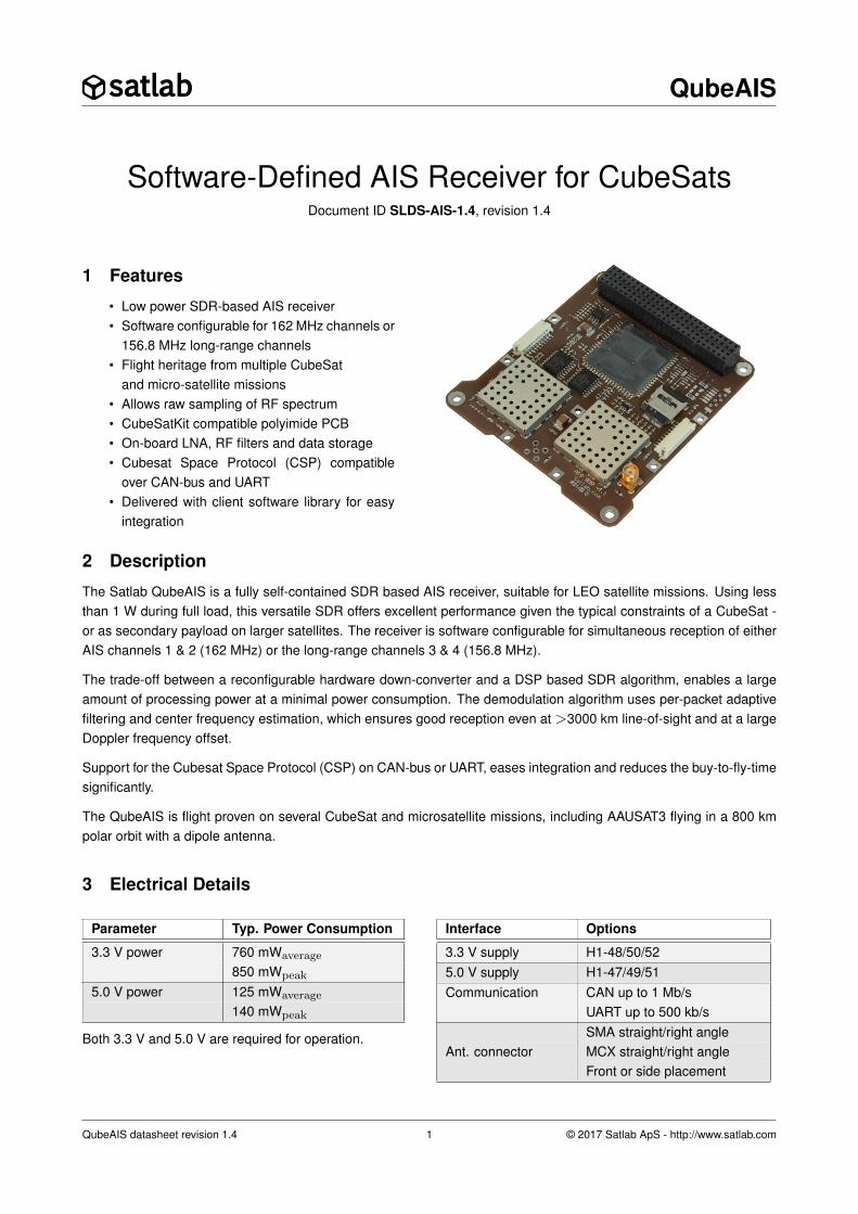
The Satlab QubeAIS is a fully self-contained SDR based AIS receiver, suitable for LEO satellite missions. Using lessthan 1 W during full load, this versatile SDR offers excellent performance given the typical constraints of a CubeSat -or as secondary payload on larger satellites. The receiver is software configurable for simultaneous reception of eitherAIS channels 1 & 2 (162 MHz) or the long-range channels 3 & 4 (156.8 MHz).
The trade-off between a reconfigurable hardware down-converter and a DSP based SDR algorithm, enables a largeamount of processing power at a minimal power consumption. The demodulation algorithm uses per-packet adaptivefiltering and center frequency estimation, which ensures good reception even at >3000 km line-of-sight and at a largeDoppler frequency offset.
Support for the Cubesat Space Protocol (CSP) on CAN-bus or UART, eases integration and reduces the buy-to-fly-timesignificantly.
The QubeAIS is flight proven on several CubeSat and microsatellite missions, including AAUSAT3 flying in a 800 kmpolar orbit with a dipole antenna.
3 Electrical Details
Parameter Typ. Power Consumption
3.3 V power 760 mWaverage
850 mWpeak
5.0 V power 125 mWaverage
140 mWpeak
Both 3.3 V and 5.0 V are required for operation.
Interface Options
3.3 V supply H1-48/50/525.0 V supply H1-47/49/51Communication CAN up to 1 Mb/s
UART up to 500 kb/sSMA straight/right angle
Ant. connector MCX straight/right angleFront or side placement
QubeAIS datasheet revision 1.4 1 © 2017 Satlab ApS - http://www.satlab.com

QubeAIS
4 Hardware Overview
The Satlab QubeAIS uses a low-IF frontend in conjunction with a 16-bit fixed point DSP to maximize performance atlow power consumption. This also allows a single frontend to be used for receiving both AIS channels, on 162 or 156.8MHz, at the same time. The following block diagram outlines the main hardware components of the receiver:
Figure 1: Overview of the hardware structure
The receiver allows for two placements of the RF connector, RF1 or RF2. Each connector is followed by a Low PassFilter (LPF) to reduce the influence of strong nearby transmitters, such as satellite downlink in the UHF- and S-band.If the satellite uses downlink in the VHF band, please consult Satlab ApS before ordering. An RF switch controlled bythe DSP selects which input connector to use.
The on-board LNA ensures a good noise figure for the overall system, and simplifies the final integration process asthe system only requires a passive antenna and the QubeAIS. The LNA on the unused input is powered down by theDSP to conserve power.
The SAW filter covers the entire marine VHF band, to increase out-of-band rejection, while allowing the receiver tobe tuned to both the 162 MHz and 156.8 MHz AIS channels - or any future allocations. As long as two AIS channelsare allocated in the marine VHF band, and no more than 50-150 kHz apart, the receiver will be able to receive bothchannels at the same time (with a software update to re-tune the receiver).
The RF frontend performs single-conversion to a low IF, while providing good image rejection using a built-in IF filter.The filter is reprogrammable to 100, 150 or 200 kHz bandwith. The default 100 kHz is sufficient to contain both AISchannels on 162 or 156.8 MHz. Reprogrammable RF, IF and ADC gains are used to ensure high dynamic range andreconfigurability after launch.
A 12-bit ADC is used to digitize the filtered IF and is the only part running from the 5.0 V DC supply.
The DSP is the central part of the design. It contains RAM, flash and interfaces for communication and data storage.Channel filtering, GMSK demodulation and decoding of both of the AIS channels are all executed in the DSP. A packetdetector estimates key parameters for each individual AIS message, and passes these on to the packet filter anddemodulator, to ensure good reception in LEO. The full algorithm has been optimized for the 16 bit fixed point DSP, toallow fast processing at low power consumption. A special operating mode allows the DSP to save raw IF samples topersistent storage, for download and processing on the ground.
Connected to the DSP are two 16 MB NOR-flashes and a 1 GB industrial grade SD-card with built-in error correctioncapabilities. The SD-card is the primary application and data storage for the receiver, while one of the NOR-flashes actsas backup storage in case the SD-card fails. The other NOR-flash is used as configuration memory and is operated inread-only mode after launch.
QubeAIS datasheet revision 1.4 2 © 2017 Satlab ApS - http://www.satlab.com
QubeAIS
5 Software Overview
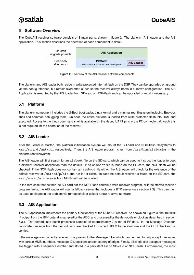
The QubeAIS receiver software consists of 3 main parts, shown in figure 2: The platform, AIS loader and the AISapplication. This section describes the operation of each component in detail.
Figure 2: Overview of the AIS receiver software components
The platform and AIS loader both reside in write-protected internal flash on the DSP. They can be upgraded on groundvia the debug interface, but remain fixed after launch so the receiver always boots in a known configuration. The AISApplication is executed by the AIS loader from SD-card or NOR-flash and can be upgraded on-orbit if necessary.
5.1 Platform
The platform component includes the U-Boot bootloader, Linux kernel and a minimal root filesystem including Busyboxshell and common debugging tools. On boot, the entire platform is loaded from write-protected flash into RAM andexecuted. Access to the Linux command shell is available on the debug UART pins in the P2 connector, although thisis not required for the operation of the receiver.
5.2 AIS Loader
After the kernel is started, the platform initialization system will mount the SD-card and NOR-flash filesystems to/mnt/sd and /mnt/nor respectively. Then, the AIS loader program is run from /usr/bin/aisloader in theplatform root filesystem.
The AIS loader will first search for an aisboot file on the SD-card, which can be used to instruct the loader to boota different receiver application than the default. If no aisboot file is found on the SD-card, the NOR-flash will bechecked. If the NOR-flash does not contain an aisboot file either, the AIS loader will check for the existence of thedefault receiver at /mnt/sd/p/ais and run it if it exists. In case no default receiver is found on the SD-card, the/mnt/nor/p/ais receiver from NOR-flash will be started.
In the rare case that neither the SD-card nor the NOR-flash contain a valid receiver program, or if the started receiverprogram faults, the AIS loader will start a fallback server that includes a BTP server (see section 7.3). This can thenbe used to diagnose the problem via remote shell or upload a new receiver software.
5.3 AIS Application
The AIS application implements the primary functionality of the QubeAIS receiver. As shown on Figure 3, the 100 kHzIF output from the RF-frontend is sampled by the ADC, and processed by the demodulator block as described in section5.3.1. The demodulator batch processes samples of approximately 700 ms of RF data. In the Message Decoder,candidate message from the demodulator are checked for correct HDLC frame structure and the CRC checksum isverified.
If the message was correctly received, it is passed to the Message Filter which can be used to only accept messageswith certain MMSI numbers, message IDs, positions and/or country of origin. Finally, all single-slot accepted messagesare tagged with a sequence number and stored in a persistent list on SD-card or NOR-flash. Furthermore, the most
QubeAIS datasheet revision 1.4 3 © 2017 Satlab ApS - http://www.satlab.com
QubeAIS
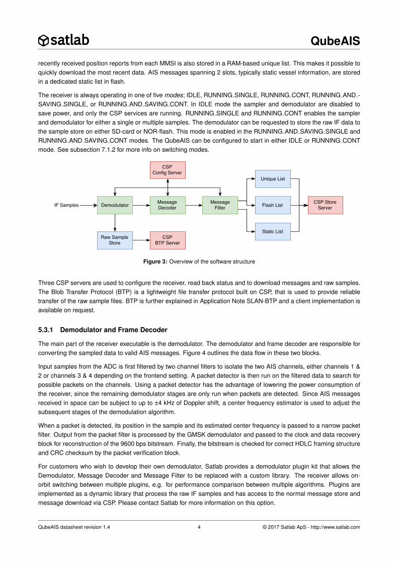
recently received position reports from each MMSI is also stored in a RAM-based unique list. This makes it possible toquickly download the most recent data. AIS messages spanning 2 slots, typically static vessel information, are storedin a dedicated static list in flash.
The receiver is always operating in one of five modes; IDLE, RUNNING SINGLE, RUNNING CONT, RUNNING AND -SAVING SINGLE, or RUNNING AND SAVING CONT. In IDLE mode the sampler and demodulator are disabled tosave power, and only the CSP services are running. RUNNING SINGLE and RUNNING CONT enables the samplerand demodulator for either a single or multiple samples. The demodulator can be requested to store the raw IF data tothe sample store on either SD-card or NOR-flash. This mode is enabled in the RUNNING AND SAVING SINGLE andRUNNING AND SAVING CONT modes. The QubeAIS can be configured to start in either IDLE or RUNNING CONTmode. See subsection 7.1.2 for more info on switching modes.
Figure 3: Overview of the software structure
Three CSP servers are used to configure the receiver, read back status and to download messages and raw samples.The Blob Transfer Protocol (BTP) is a lightweight file transfer protocol built on CSP, that is used to provide reliabletransfer of the raw sample files. BTP is further explained in Application Note SLAN-BTP and a client implementation isavailable on request.
5.3.1 Demodulator and Frame Decoder
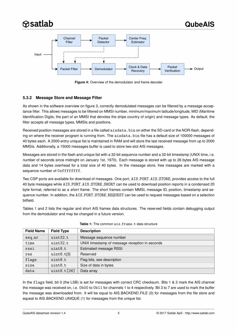
The main part of the receiver executable is the demodulator. The demodulator and frame decoder are responsible forconverting the sampled data to valid AIS messages. Figure 4 outlines the data flow in these two blocks.
Input samples from the ADC is first filtered by two channel filters to isolate the two AIS channels, either channels 1 &2 or channels 3 & 4 depending on the frontend setting. A packet detector is then run on the filtered data to search forpossible packets on the channels. Using a packet detector has the advantage of lowering the power consumption ofthe receiver, since the remaining demodulator stages are only run when packets are detected. Since AIS messagesreceived in space can be subject to up to ±4 kHz of Doppler shift, a center frequency estimator is used to adjust thesubsequent stages of the demodulation algorithm.
When a packet is detected, its position in the sample and its estimated center frequency is passed to a narrow packetfilter. Output from the packet filter is processed by the GMSK demodulator and passed to the clock and data recoveryblock for reconstruction of the 9600 bps bitstream. Finally, the bitstream is checked for correct HDLC framing structureand CRC checksum by the packet verification block.
For customers who wish to develop their own demodulator, Satlab provides a demodulator plugin kit that allows theDemodulator, Message Decoder and Message Filter to be replaced with a custom library. The receiver allows on-orbit switching between multiple plugins, e.g. for performance comparison between multiple algorithms. Plugins areimplemented as a dynamic library that process the raw IF samples and has access to the normal message store andmessage download via CSP. Please contact Satlab for more information on this option.
QubeAIS datasheet revision 1.4 4 © 2017 Satlab ApS - http://www.satlab.com
QubeAIS
Figure 4: Overview of the demodulator and frame decoder
5.3.2 Message Store and Message Filter
As shown in the software overview on figure 3, correctly demodulated messages can be filtered by a message accep-tance filter. This allows messages to be filtered on MMSI number, minimum/maximum latitude/longitude, MID (MaritimeIdentification Digits, the part of an MMSI that denotes the ships country of origin) and message types. As default, thefilter accepts all message types, MMSIs and positions.
Received position messages are stored in a file called aisdata.bin on either the SD-card or the NOR-flash, depend-ing on where the receiver program is running from. The aisdata.bin file has a default size of 100000 messages of40 bytes each. A 2000-entry unique list is maintained in RAM and will store the last received message from up to 2000MMSIs. Additionally, a 15000 messages buffer is used to store two-slot AIS messages.
Messages are stored in the flash and unique list with a 32-bit sequence number and a 32-bit timestamp (UNIX time, i.e.number of seconds since midnight on January 1st, 1970). Each message is stored with up to 26 bytes AIS messagedata and 14 bytes overhead for a total size of 40 bytes. In the message store, free messages are marked with asequence number of 0xffffffff.
Two CSP ports are available for download of messages. One port, AIS PORT AIS STORE, provides access to the full40 byte messages while AIS PORT AIS STORE SHORT can be used to download position reports in a condensed 20byte format, referred to as a short frame. The short frames contain MMSI, message ID, position, timestamp and se-quence number. In addition, the AIS PORT STORE REQUEST can be used to request messages based on a selectionbitfield.
Tables 1 and 2 lists the regular and short AIS frames data structures. The reserved fields contain debugging outputfrom the demodulator and may be changed in a future version.
Table 1: The common ais frame t data structure
Field Name Field Type Description
seq nr uint32 t Message sequence numbertime uint32 t UNIX timestamp of message reception in secondsrssi uint8 t Estimated message RSSIres uint8 t[3] Reservedflags uint8 t Flag bits, see descriptionsize uint8 t Size of data in bytesdata uint8 t[26] Data array
In the flags field, bit 0 (the LSB) is set for messages with correct CRC checksum. Bits 1 & 2 mark the AIS channelthe message was received on, i.e. 0b00 to 0b11 for channels 1 to 4 respectively. Bit 3 to 7 are used to mark the bufferthe message was downloaded from. It will be equal to AIS BACKEND FILE (0) for messages from the file store andequeal to AIS BACKEND UNIQUE (1) for messages from the unique list.
QubeAIS datasheet revision 1.4 5 © 2017 Satlab ApS - http://www.satlab.com
QubeAIS
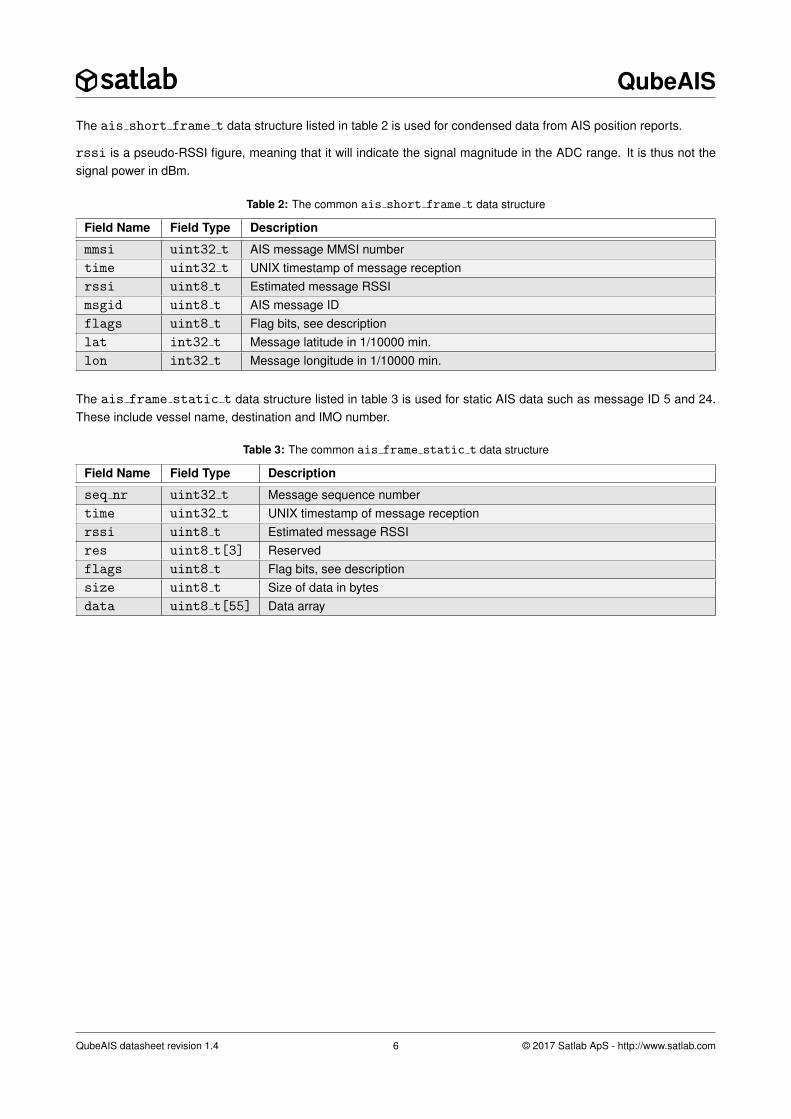
The ais short frame t data structure listed in table 2 is used for condensed data from AIS position reports.
rssi is a pseudo-RSSI figure, meaning that it will indicate the signal magnitude in the ADC range. It is thus not thesignal power in dBm.
Table 2: The common ais short frame t data structure
Field Name Field Type Description
mmsi uint32 t AIS message MMSI numbertime uint32 t UNIX timestamp of message receptionrssi uint8 t Estimated message RSSImsgid uint8 t AIS message IDflags uint8 t Flag bits, see descriptionlat int32 t Message latitude in 1/10000 min.lon int32 t Message longitude in 1/10000 min.
The ais frame static t data structure listed in table 3 is used for static AIS data such as message ID 5 and 24.These include vessel name, destination and IMO number.
Table 3: The common ais frame static t data structure
Field Name Field Type Description
seq nr uint32 t Message sequence numbertime uint32 t UNIX timestamp of message receptionrssi uint8 t Estimated message RSSIres uint8 t[3] Reservedflags uint8 t Flag bits, see descriptionsize uint8 t Size of data in bytesdata uint8 t[55] Data array
QubeAIS datasheet revision 1.4 6 © 2017 Satlab ApS - http://www.satlab.com
QubeAIS
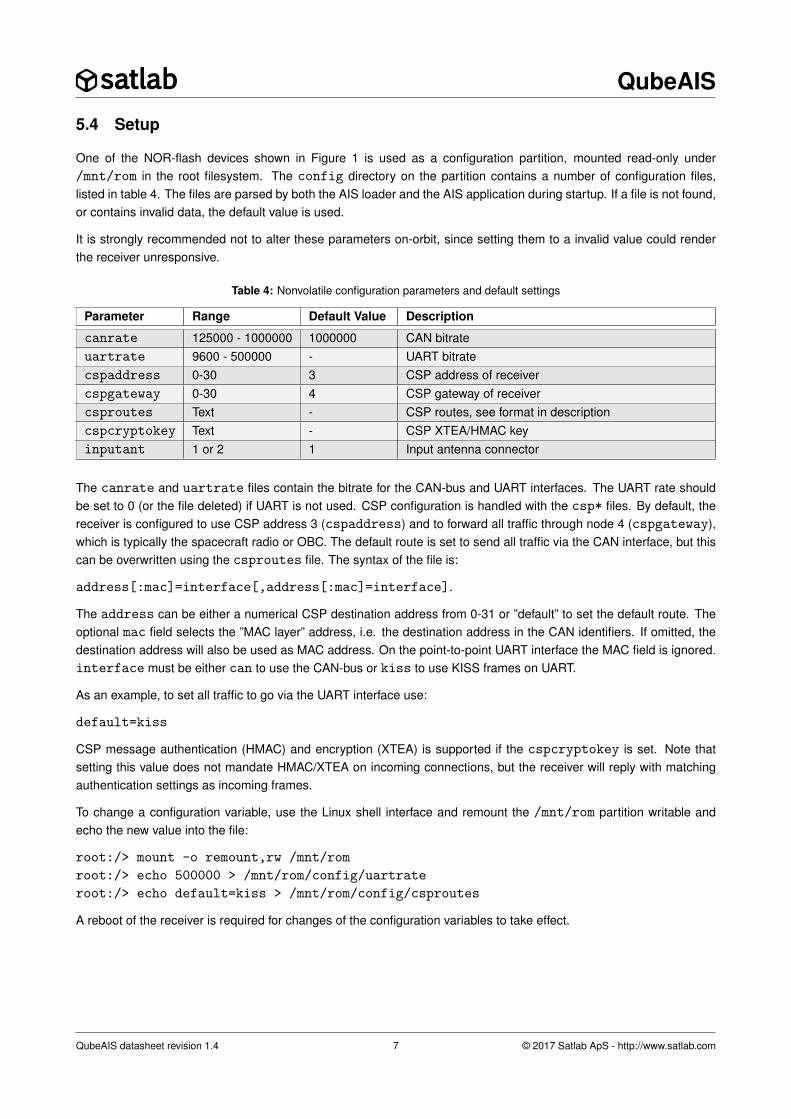
5.4 Setup
One of the NOR-flash devices shown in Figure 1 is used as a configuration partition, mounted read-only under/mnt/rom in the root filesystem. The config directory on the partition contains a number of configuration files,listed in table 4. The files are parsed by both the AIS loader and the AIS application during startup. If a file is not found,or contains invalid data, the default value is used.
It is strongly recommended not to alter these parameters on-orbit, since setting them to a invalid value could renderthe receiver unresponsive.
Table 4: Nonvolatile configuration parameters and default settings
Parameter Range Default Value Description
canrate 125000 - 1000000 1000000 CAN bitrateuartrate 9600 - 500000 - UART bitratecspaddress 0-30 3 CSP address of receivercspgateway 0-30 4 CSP gateway of receivercsproutes Text - CSP routes, see format in descriptioncspcryptokey Text - CSP XTEA/HMAC keyinputant 1 or 2 1 Input antenna connector
The canrate and uartrate files contain the bitrate for the CAN-bus and UART interfaces. The UART rate shouldbe set to 0 (or the file deleted) if UART is not used. CSP configuration is handled with the csp* files. By default, thereceiver is configured to use CSP address 3 (cspaddress) and to forward all traffic through node 4 (cspgateway),which is typically the spacecraft radio or OBC. The default route is set to send all traffic via the CAN interface, but thiscan be overwritten using the csproutes file. The syntax of the file is:
address[:mac]=interface[,address[:mac]=interface].
The address can be either a numerical CSP destination address from 0-31 or ”default” to set the default route. Theoptional mac field selects the ”MAC layer” address, i.e. the destination address in the CAN identifiers. If omitted, thedestination address will also be used as MAC address. On the point-to-point UART interface the MAC field is ignored.interface must be either can to use the CAN-bus or kiss to use KISS frames on UART.
As an example, to set all traffic to go via the UART interface use:
default=kiss
CSP message authentication (HMAC) and encryption (XTEA) is supported if the cspcryptokey is set. Note thatsetting this value does not mandate HMAC/XTEA on incoming connections, but the receiver will reply with matchingauthentication settings as incoming frames.
To change a configuration variable, use the Linux shell interface and remount the /mnt/rom partition writable andecho the new value into the file:
root:/> mount -o remount,rw /mnt/rom
root:/> echo 500000 > /mnt/rom/config/uartrate
root:/> echo default=kiss > /mnt/rom/config/csproutes
A reboot of the receiver is required for changes of the configuration variables to take effect.
QubeAIS datasheet revision 1.4 7 © 2017 Satlab ApS - http://www.satlab.com

QubeAIS
6 Receiver Performance
In figure 5 the typical reception performance for the AIS receiver is shown. The bold line shows the average receptionperformance over the full temperature range from -40°C to +70°C and for the two AIS frequencies on 161.975 MHzand 162.025 MHz ±3 kHz Doppler shift. The three thinner lines shows the average over the frequency span, but formaximum, minimum and typical operating temperatures.
Figure 5: Typical receiver performance as a function of signal power averaged over AIS channel 1 and2 ±3 kHz Doppler.
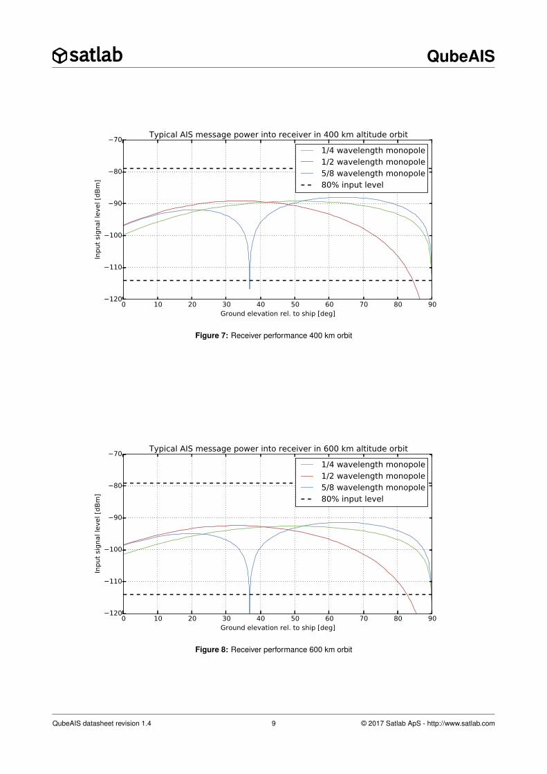
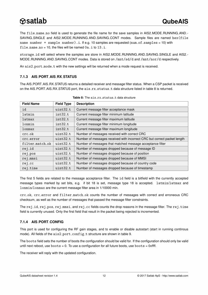
This can be related to a simplified link budget simulation. The basis of this simplified signal level budget is a ClassA vessel with vertical antenna, illustrated in figure 6. The ship transponder output is assumed to be 12.5 W, with 1dB loss from transponder to the antenna. The 3 ship antenna types are assumed over ideal ground plane and on thesatellite side a 0 dBi antenna and 1 dB cable loss is assumed. This results in the signal levels into the receiver asshown in figure 7 and 8 for a 400 km and 600 km orbit respectively. The two dashed lines shows the reception limitsfor the receiver, showning that with the default settings of the receiver, the AIS signal strength falls nicely within theoperating range of the AIS receiver.
Satellite
Ground Elevation Angle
OrbitAltitudeClass A Vessel
Figure 6: Simplified receiver sensitivity simulation
It should be noted that this is a very simplified calculation and a detailed link budget analysis should be performed foreach mission individually.
QubeAIS datasheet revision 1.4 8 © 2017 Satlab ApS - http://www.satlab.com
QubeAIS
0 10 20 30 40 50 60 70 80 90Ground elevation rel. to ship [deg]
120
110
100
90
80
70
Input
signal le
vel [d
Bm
]
Typical AIS message power into receiver in 400 km altitude orbit
1/4 wavelength monopole1/2 wavelength monopole5/8 wavelength monopole80% input level
Figure 7: Receiver performance 400 km orbit
0 10 20 30 40 50 60 70 80 90Ground elevation rel. to ship [deg]
120
110
100
90
80
70
Input
signal le
vel [d
Bm
]
Typical AIS message power into receiver in 600 km altitude orbit
1/4 wavelength monopole1/2 wavelength monopole5/8 wavelength monopole80% input level
Figure 8: Receiver performance 600 km orbit
QubeAIS datasheet revision 1.4 9 © 2017 Satlab ApS - http://www.satlab.com

QubeAIS
7 Software Interface Description
The QubeAIS receiver is controlled using the Cubesat Space Protocol (CSP) via CAN-bus or UART/KISS. This chapterlists the available service ports and data structures used to communicate with the device. The CSP address of thereceiver is set using the configuration variables as explained in section 5.4. Table 5 lists the available service portswith a short description of each service.
When the device is booted, it will automatically start listening for requests on the service ports. Each service can becategorized as either Configuration and Status, Message Store or Blob Transfer Protocol.
All data structures are packed, i.e. no alignment padding is used between the fields, and unless otherwise noted allfields are transferred in network byte order (big endian).
This chapter is meant to serve as a reference. Satlab supplies a support library, libsatlab, containing an ais.h
header file with all data structures and wrapper functions around the CSP calls to simplify integration of the receiver.
Table 5: CSP service names and ports.
Port Name Port Number Service Description
AIS PORT STATUS 8 AIS receiver statusAIS PORT MODE 9 Receiver mode configurationAIS PORT AIS STORE 11 Message store for long packetsAIS PORT AIS STORE SHORT 12 Message store for short packetsAIS PORT BTP 13 Blob Transfer ProtocolAIS PORT AIS RX STATUS 17 Detailed AIS receiver and message filter statusAIS PORT CONFIG 19 AIS general configurationAIS PORT AIS STORE STATIC 20 Message store for static packetsAIS PORT STORE CONFIG 21 Message store configAIS PORT STORE REQUEST 22 Message store bitmap requestAIS PORT TIME CONFIG 23 Time configurationAIS PORT CHANNEL CONFIG 24 Channel configurationAIS PORT DEMOD CONFIG 30 Custom demodulator configurationAIS PORT DEMOD USER 31 Custom demodulator user port
QubeAIS datasheet revision 1.4 10 © 2017 Satlab ApS - http://www.satlab.com

QubeAIS
7.1 Configuration and Status Interface
7.1.1 AIS PORT STATUS
This port is used for reading the current status of the receiver, and to verify that it is operating nominally. When theQubeAIS receives a CSP packet on the AIS PORT STATUS port, it will return the data structure listed in table 6.
Table 6: The ais2 port status t data structure
Field Name Field Type Description
critical errors uint8 t Number of critical errors since bootwarnings uint8 t Number of warnings since bootruns uint16 t Number of samples processed since bootpacks detected uint16 t Number of packets detected since bootrunning from uint8 t Storage ID where the program is runningbootcount uint16 t Total number of times the system has bootedcrc ok uint32 t Number of received messages with correct CRC since bootunique mmsi uint16 t Number of unique MMSIs received since bootlatest mmsi uint32 t MMSI of the last received messagelatest long int32 t Longitude of last received message in 1/10000 min.latest lat int32 t Latitude of last received message in 1/10000 min.rssi uint8 t RSSI of 100 kHz channel bandwidthflags uint8 t Status flags
The running from field will return AIS RUNNING FROM SD (numerical value 0x00) when running from the SD-card,and AIS RUNNING FROM NOR (numerical value 0x01) when running from the NOR-flash.
When the status is requested, the receiver will measure the RSSI in the receiver frontend and return it in the rssi
field. The field step size is 0.5 dBm, and the range is shifted so an rssi field value of 0 corresponds to -140 dBm.
The flags byte is currently unused and will always be read as 0.
7.1.2 AIS PORT MODE
This port sets the receive mode of the QubeAIS as described in section 5. Depending on configuration, the system willstart in either idle or continuous mode. As default the receiver will start in continuous mode.
Table 7 shows the fields in the ais2 port mode t data structure.
Table 7: The ais2 port mode t data structure
Field Name Field Type Description
command code uint8 t Sets the new receiver modestorage id uint8 t Storage where RAW samples should be stored. 0=SD-card, 1=NOR-flashfile name no uint8 t First sample file numbernum of samples uint8 t Number of samples to process
The command code field should be one of AIS2 MODE IDLE (value 0), AIS2 MODE RUNNING SINGLE (value 1),AIS2 MODE RUNNING CONT (value 2), AIS2 MODE RUNNING AND SAVING SINGLE (value 3),AIS2 MODE RUNNING AND SAVING CONT (value 4).
num of samples is only used in AIS2 MODE RUNNING CONT and AIS2 MODE RUNNING AND SAVING CONT.If the value is larger than 0, the receiver will go to IDLE mode when the specified number of samples has beenprocessed. If num of samples is 0, the receiver will continue to process samples until manually set in IDLE mode.
QubeAIS datasheet revision 1.4 11 © 2017 Satlab ApS - http://www.satlab.com
QubeAIS
The file name no field is used to generate the file name for the save samples in AIS2 MODE RUNNING AND -SAVING SINGLE and AIS2 MODE RUNNING AND SAVING CONT modes. Sample files are named hex(file
name number + sample number).i. If e.g. 10 samples are requested (num of samples = 10) withfile name no = 10, the files will be named 0a.i to 13.i.
storage id will select where the samples are store in AIS2 MODE RUNNING AND SAVING SINGLE and AIS2 -MODE RUNNING AND SAVING CONT modes. Data is stored on /mnt/sd/d and /mnt/nor/d respectively.
An ais2 port mode t with the new settings will be returned when a mode request is received.
7.1.3 AIS PORT AIS RX STATUS
The AIS PORT AIS RX STATUS returns a detailed receiver and message filter status. When a CSP packet is receivedon the AIS PORT AIS RX STATUS port, the ais rx status t data structure listed in table 8 is returned.
Table 8: The ais rx status t data structure
Field Name Field Type Description
id uint32 t Current message filter acceptance masklatmin int32 t Current message filter minimum latitudelatmax int32 t Current message filter maximum latitudelonmin int32 t Current message filter minimum longitudelonmax int32 t Current message filter maximum longitudecrc ok uint32 t Number of messages received with correct CRCcrc error uint32 t Number of messages received with incorrect CRC but correct packet lengthfilter match ok uint32 t Number of messages that matched message acceptance filterrej id uint32 t Number of messages dropped because of message IDrej pos uint32 t Number of messages dropped because of positionrej mmsi uint32 t Number of messages dropped because of MMSIrej cc uint32 t Number of messages dropped because of country coderej time uint32 t Number of messages dropped because of timestamp
The first 5 fields are related to the message acceptance filter. The id field is a bitfield with the currently acceptedmessage types marked by set bits, e.g. if bit 18 is set, message type 18 is accepted. latmin/latmax andlonmin/lonmax are the current message filter area in 1/10000 min.
crc ok, crc error and filter match ok counts the number of messages with correct and erroneous CRCchecksum, as well as the number of messages that passed the message filter constraints.
The rej id, rej pos, rej mmsi, and rej cc fields counts the drop reasons in the message filter. The rej time
field is currently unused. Only the first field that result in the packet being rejected is incremented.
7.1.4 AIS PORT CONFIG
This port is used for configuring the RF gain stages, and to enable or disable autostart (start in running continousmode). All fields of the ais2 port config t structure are shown in table 9.
The boots field sets the number of boots the configuration should be valid for. If the configuration should only be validuntil next reboot, use boots = 0. To use a configuration for all future boots, use boots = 0xffff.
The receiver will reply with the updated configuration.
QubeAIS datasheet revision 1.4 12 © 2017 Satlab ApS - http://www.satlab.com

QubeAIS
Table 9: The ais2 port config t data structure
Field Name Field Type Description
boots uint16 t How many boots the configuration should be validadc gain uint8 t ADC gain value. Use 0xff to keep current valuefilter gain uint8 t RF frontend filter gain value. Use 0xff to keep current valuelna gain uint8 t RF frontend LNA gain value. Use 0xff to keep current valueautostart uint8 t If nonzero, enable receiver autostart
7.1.5 AIS PORT TIME CONFIG
This port allows the system time of the QubeAIS to be adjusted and read back. The receiver does not have an RTCso the system time is undefined after startup. Since all received AIS frames are timestamped with the system time, itis thus recommended to set the time when the system is powered on. The time format is UNIX time, i.e. number ofseconds since midnight on January 1st, 1970, with each timestamp is split into seconds and nanoseconds components.
To set the system time, send an ais port time config set time req with the new time. The receiver will replywith an ais port time config set time rep structure containing an error/success return value and the updatedsystem time.
To set the receiver time, send an ais port time config set time req with the sec and nsec fields set to thenew time in seconds and nanoseconds since 00:00:00 on January 1st 1970 (also known as “Epoch time”).
Table 10: The ais port time config set time req t data structure
Field Name Field Type Description
type uint8 t Request type, must be AIS PORT TIME CONFIG SET TIME
sec uint32 t New secondsnsec uint32 t New nanoseconds
The receiver will reply with an ais port time config set time rep packet containing the same type field andan error code (0 for success, error code on error) and the updated time. The error codes are listed in libsatlab.
Table 11: The ais port time config set time rep t data structure
Field Name Field Type Description
type uint8 t Request type, must be AIS PORT TIME CONFIG SET TIME
error uint8 t Error codesec uint32 t New secondsnsec uint32 t New nanoseconds
To request the current system time, send a single byte ais port time config get time req. The receiver willreply with an ais port time config get time rep which is identical to the set time reply, except the type will beAIS PORT TIME CONFIG GET TIME.
Table 12: The ais port time config get time req t data structure
Field Name Field Type Description
type uint8 t Request type, must be AIS PORT TIME CONFIG GET TIME
QubeAIS datasheet revision 1.4 13 © 2017 Satlab ApS - http://www.satlab.com
QubeAIS
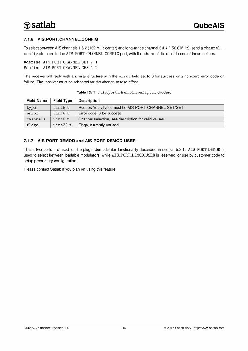
7.1.6 AIS PORT CHANNEL CONFIG
To select between AIS channels 1 & 2 (162 MHz center) and long-range channel 3 & 4 (156.8 MHz), send a channel -
config structure to the AIS PORT CHANNEL CONFIG port, with the channel field set to one of these defines:
#define AIS PORT CHANNEL CH1 2 1
#define AIS PORT CHANNEL CH3 4 2
The receiver will reply with a similar structure with the error field set to 0 for success or a non-zero error code onfailure. The receiver must be rebooted for the change to take effect.
Table 13: The ais port channel config data structure
Field Name Field Type Description
type uint8 t Request/reply type, must be AIS PORT CHANNEL SET/GETerror uint8 t Error code, 0 for successchannels uint8 t Channel selection, see description for valid valuesflags uint32 t Flags, currently unused
7.1.7 AIS PORT DEMOD and AIS PORT DEMOD USER
These two ports are used for the plugin demodulator functionality described in section 5.3.1. AIS PORT DEMOD isused to select between loadable modulators, while AIS PORT DEMOD USER is reserved for use by customer code tosetup proprietary configuration.
Please contact Satlab if you plan on using this feature.
QubeAIS datasheet revision 1.4 14 © 2017 Satlab ApS - http://www.satlab.com
QubeAIS
7.2 Message Store Interface
7.2.1 AIS PORT STORE
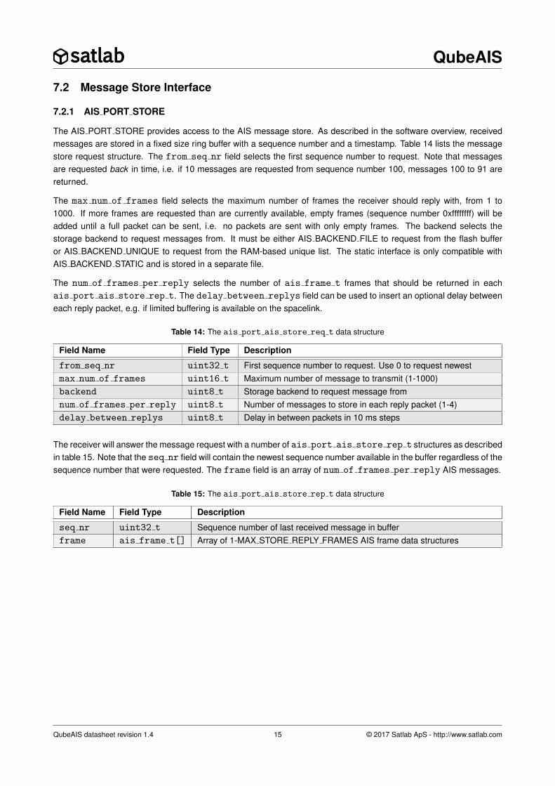
The AIS PORT STORE provides access to the AIS message store. As described in the software overview, receivedmessages are stored in a fixed size ring buffer with a sequence number and a timestamp. Table 14 lists the messagestore request structure. The from seq nr field selects the first sequence number to request. Note that messagesare requested back in time, i.e. if 10 messages are requested from sequence number 100, messages 100 to 91 arereturned.
The max num of frames field selects the maximum number of frames the receiver should reply with, from 1 to1000. If more frames are requested than are currently available, empty frames (sequence number 0xffffffff) will beadded until a full packet can be sent, i.e. no packets are sent with only empty frames. The backend selects thestorage backend to request messages from. It must be either AIS BACKEND FILE to request from the flash bufferor AIS BACKEND UNIQUE to request from the RAM-based unique list. The static interface is only compatible withAIS BACKEND STATIC and is stored in a separate file.
The num of frames per reply selects the number of ais frame t frames that should be returned in eachais port ais store rep t. The delay between replys field can be used to insert an optional delay betweeneach reply packet, e.g. if limited buffering is available on the spacelink.
Table 14: The ais port ais store req t data structure
Field Name Field Type Description
from seq nr uint32 t First sequence number to request. Use 0 to request newestmax num of frames uint16 t Maximum number of message to transmit (1-1000)backend uint8 t Storage backend to request message fromnum of frames per reply uint8 t Number of messages to store in each reply packet (1-4)delay between replys uint8 t Delay in between packets in 10 ms steps
The receiver will answer the message request with a number of ais port ais store rep t structures as describedin table 15. Note that the seq nr field will contain the newest sequence number available in the buffer regardless of thesequence number that were requested. The frame field is an array of num of frames per reply AIS messages.
Table 15: The ais port ais store rep t data structure
Field Name Field Type Description
seq nr uint32 t Sequence number of last received message in bufferframe ais frame t[] Array of 1-MAX STORE REPLY FRAMES AIS frame data structures
QubeAIS datasheet revision 1.4 15 © 2017 Satlab ApS - http://www.satlab.com
QubeAIS
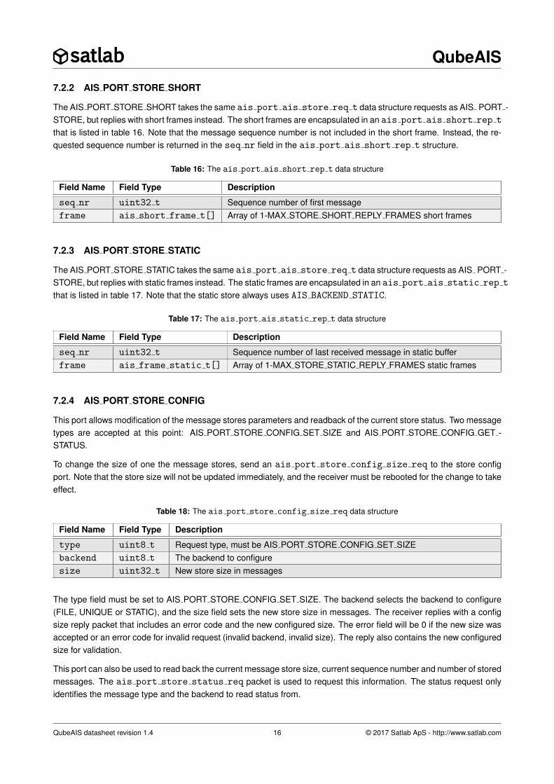
7.2.2 AIS PORT STORE SHORT
The AIS PORT STORE SHORT takes the same ais port ais store req t data structure requests as AIS PORT -STORE, but replies with short frames instead. The short frames are encapsulated in an ais port ais short rep t
that is listed in table 16. Note that the message sequence number is not included in the short frame. Instead, the re-quested sequence number is returned in the seq nr field in the ais port ais short rep t structure.
Table 16: The ais port ais short rep t data structure
Field Name Field Type Description
seq nr uint32 t Sequence number of first messageframe ais short frame t[] Array of 1-MAX STORE SHORT REPLY FRAMES short frames
7.2.3 AIS PORT STORE STATIC
The AIS PORT STORE STATIC takes the same ais port ais store req t data structure requests as AIS PORT -STORE, but replies with static frames instead. The static frames are encapsulated in an ais port ais static rep t
that is listed in table 17. Note that the static store always uses AIS BACKEND STATIC.
Table 17: The ais port ais static rep t data structure
Field Name Field Type Description
seq nr uint32 t Sequence number of last received message in static bufferframe ais frame static t[] Array of 1-MAX STORE STATIC REPLY FRAMES static frames
7.2.4 AIS PORT STORE CONFIG
This port allows modification of the message stores parameters and readback of the current store status. Two messagetypes are accepted at this point: AIS PORT STORE CONFIG SET SIZE and AIS PORT STORE CONFIG GET -STATUS.
To change the size of one the message stores, send an ais port store config size req to the store configport. Note that the store size will not be updated immediately, and the receiver must be rebooted for the change to takeeffect.
Table 18: The ais port store config size req data structure
Field Name Field Type Description
type uint8 t Request type, must be AIS PORT STORE CONFIG SET SIZEbackend uint8 t The backend to configuresize uint32 t New store size in messages
The type field must be set to AIS PORT STORE CONFIG SET SIZE. The backend selects the backend to configure(FILE, UNIQUE or STATIC), and the size field sets the new store size in messages. The receiver replies with a configsize reply packet that includes an error code and the new configured size. The error field will be 0 if the new size wasaccepted or an error code for invalid request (invalid backend, invalid size). The reply also contains the new configuredsize for validation.
This port can also be used to read back the current message store size, current sequence number and number of storedmessages. The ais port store status req packet is used to request this information. The status request onlyidentifies the message type and the backend to read status from.
QubeAIS datasheet revision 1.4 16 © 2017 Satlab ApS - http://www.satlab.com
QubeAIS
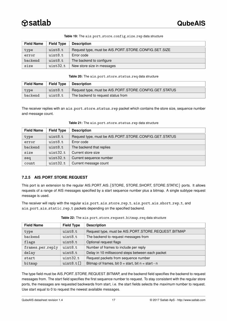
Table 19: The ais port store config size rep data structure
Field Name Field Type Description
type uint8 t Request type, must be AIS PORT STORE CONFIG SET SIZEerror uint8 t Error codebackend uint8 t The backend to configuresize uint32 t New store size in messages
Table 20: The ais port store status req data structure
Field Name Field Type Description
type uint8 t Request type, must be AIS PORT STORE CONFIG GET STATUSbackend uint8 t The backend to request status from
The receiver replies with an ais port store status rep packet which contains the store size, sequence numberand message count.
Table 21: The ais port store status rep data structure
Field Name Field Type Description
type uint8 t Request type, must be AIS PORT STORE CONFIG GET STATUSerror uint8 t Error codebackend uint8 t The backend that repliessize uint32 t Current store sizeseq uint32 t Current sequence numbercount uint32 t Current message count
7.2.5 AIS PORT STORE REQUEST
This port is an extension to the regular AIS PORT AIS {STORE, STORE SHORT, STORE STATIC} ports. It allowsrequests of a range of AIS messages specified by a start sequence number plus a bitmap. A single subtype requestmessage is used.
The receiver will reply with the regular ais port ais store rep t, ais port ais short rep t, andais port ais static rep t packets depending on the specified backend.
Table 22: The ais port store request bitmap req data structure
Field Name Field Type Description
type uint8 t Request type, must be AIS PORT STORE REQUEST BITMAPbackend uint8 t The backend to request messages fromflags uint8 t Optional request flagsframes per reply uint8 t Number of frames to include per replydelay uint8 t Delay in 10 millisecond steps between each packetstart uint32 t Request packets from sequence numberbitmap uint8 t[] Bitmap of frames, bit 0 = start, bit n = start - n
The type field must be AIS PORT STORE REQUEST BITMAP, and the backend field specifies the backend to requestmessages from. The start field specifies the first sequence number to request. To stay consistent with the regular storeports, the messages are requested backwards from start, i.e. the start fields selects the maximum number to request.Use start equal to 0 to request the newest available messages.
QubeAIS datasheet revision 1.4 17 © 2017 Satlab ApS - http://www.satlab.com

QubeAIS
The flags byte can be used to request short frames (from backends that support it), by setting the AIS PORT STORE -REQUEST FLAG SHORT flag.
The frames per reply field sets the number of AIS messages to include in each reply packet. The delay field can beused to insert a small delay between each packet (e.g. to lower the buffering requirement on routing nodes).
The bitmap field is used to request selected messages backwards from the start sequence number. If bit n is set, thereceiver will send the message with sequence number start - n, i.e. bit 0 must be set to request the message withsequence number start. Bit 0 is the bit immediately after the delay field and bit 255 is the last bit in the packet.
The size of the bitfield is AIS PORT STORE REQUEST BITMAP SIZE which is currently set to 32 bytes (so up to 256AIS messages can be requested at a time).
7.3 Blob Transfer Protocol
The Blob Transfer Protocol (BTP) is a lightweight file transfer and remote shell protocol based on CSP. BTP supportsupload and download of files, as well as basic file operations such as list, delete, copy and move.
On the QubeAIS BTP is mainly used for downloading raw samples, and to upload new receiver software. The remoteshell interface can be used for advanced debugging if necessary.
7.3.1 AIS PORT BTP
BTP runs as a single threaded server on a single CSP port, AIS PORT BTP, and can thus only serve one connectionat a time. The BTP protocol is explained in Application Note SLAN-BTP which is available on request.
QubeAIS datasheet revision 1.4 18 © 2017 Satlab ApS - http://www.satlab.com
QubeAIS
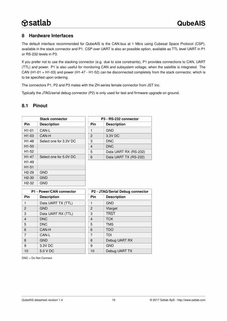
8 Hardware Interfaces
The default interface recommended for QubeAIS is the CAN-bus at 1 Mb/s using Cubesat Space Protocol (CSP),available in the stack connector and P1. CSP over UART is also an possible option, available as TTL level UART in P1or RS-232 levels in P3.
If you prefer not to use the stacking connector (e.g. due to size constraints), P1 provides connections to CAN, UART(TTL) and power. P1 is also useful for monitoring CAN and subsystem voltage, when the satellite is integrated. TheCAN (H1-01 + H1-03) and power (H1-47 - H1-52) can be disconnected completely from the stack connector, which isto be specified upon ordering.
The connectors P1, P2 and P3 mates with the ZH-series female connector from JST Inc.
Typically the JTAG/serial debug connector (P2) is only used for test and firmware upgrade on ground.
8.1 Pinout
Stack connectorPin Description
H1-01 CAN-LH1-03 CAN-HH1-48 Select one for 3.3V DCH1-50H1-52H1-47 Select one for 5.0V DCH1-49H1-51H2-29 GNDH2-30 GNDH2-32 GND
P3 - RS-232 connectorPin Description
1 GND2 3.3V DC3 DNC4 DNC5 Data UART RX (RS-232)6 Data UART TX (RS-232)
P1 - Power/CAN connectorPin Description
1 Data UART TX (TTL)2 GND3 Data UART RX (TTL)4 DNC5 DNC6 CAN-H7 CAN-L8 GND9 3.3V DC10 5.0 V DC
P2 - JTAG/Serial Debug connectorPin Description
1 GND2 Vtarget3 TRST4 TCK5 TMS6 TDO7 TDI8 Debug UART RX9 GND10 Debug UART TX
DNC = Do Not Connect
QubeAIS datasheet revision 1.4 19 © 2017 Satlab ApS - http://www.satlab.com

QubeAIS
8.2 Electrical Levels on Pins
The table below lists the minimum and maximum allowable levels on the connector pins. Exceeding these may damagethe product permanently.
Maximum Allowable LevelsPin Description Parameter Value
3.3 V DC Vmin 3.1 VVmax 3.5 VVP-P <100 mV †
5.0V DC Vmin 4.9 VVmax 5.1 VVP-P <100 mV †
RF in Pmax -20 dBmVDCmax ±5 V
CAN-L/H Vin -4 V - +16 VVin∆ -6 V - +6 VVoutL 0.5 V - 1.25 VVoutH 2.45 V - 3.3 VVout∆ 1.2 V - 3.0 V
UART-TTL VinH 2.0 V - 3.6 VVinL -0.2 V - 0.5 VVoutH (V3.3V - 0.5 V) - V3.3V
VoutL 0.0 V - 0.5 VUART-RS232 Vinmax -25 V - +25 V
Vinmin -3.0 V - +3.0 VVoutmin -5.0 V - +5.0VVouttyp -5.4 V - +5.4 V
† Although 100 mV noise is allowed on the power lines, noise here can affect the reception performance. It is advisedto keep the supply noise as low as possible.
QubeAIS datasheet revision 1.4 20 © 2017 Satlab ApS - http://www.satlab.com
QubeAIS
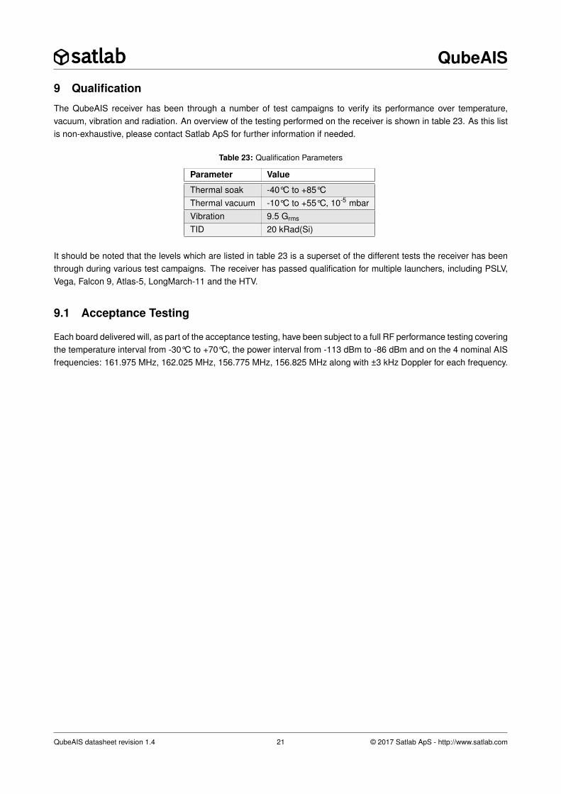
9 Qualification
The QubeAIS receiver has been through a number of test campaigns to verify its performance over temperature,vacuum, vibration and radiation. An overview of the testing performed on the receiver is shown in table 23. As this listis non-exhaustive, please contact Satlab ApS for further information if needed.
Table 23: Qualification Parameters
Parameter Value
Thermal soak -40°C to +85°CThermal vacuum -10°C to +55°C, 10-5 mbarVibration 9.5 Grms
TID 20 kRad(Si)
It should be noted that the levels which are listed in table 23 is a superset of the different tests the receiver has beenthrough during various test campaigns. The receiver has passed qualification for multiple launchers, including PSLV,Vega, Falcon 9, Atlas-5, LongMarch-11 and the HTV.
9.1 Acceptance Testing
Each board delivered will, as part of the acceptance testing, have been subject to a full RF performance testing coveringthe temperature interval from -30°C to +70°C, the power interval from -113 dBm to -86 dBm and on the 4 nominal AISfrequencies: 161.975 MHz, 162.025 MHz, 156.775 MHz, 156.825 MHz along with ±3 kHz Doppler for each frequency.
QubeAIS datasheet revision 1.4 21 © 2017 Satlab ApS - http://www.satlab.com

QubeAIS
10 Board OutlineFigure 9 shows the board with R/A SMA connectors, and pin1 markings of the ZH-series connectors.
94.73
89.03
73.66
85.73
80.01
3.81 2.54
82.67
3.50
P1 P2
P3
H1H2
1
1
1
12
12
RF1
RF2
Figure 9: Board outline and pin1 markings. Dimensions in mm.
The picture in figure 10 shows the QubeAIS receiver with straight SMA connector for the RF1 option. Note that thestraight SMA connector does not extend outside of the board outline like the right angle SMA.
Figure 10: Top view of the QubeAIS with SMA straight in the RF1 connector placement
QubeAIS datasheet revision 1.4 22 © 2017 Satlab ApS - http://www.satlab.com
QubeAIS
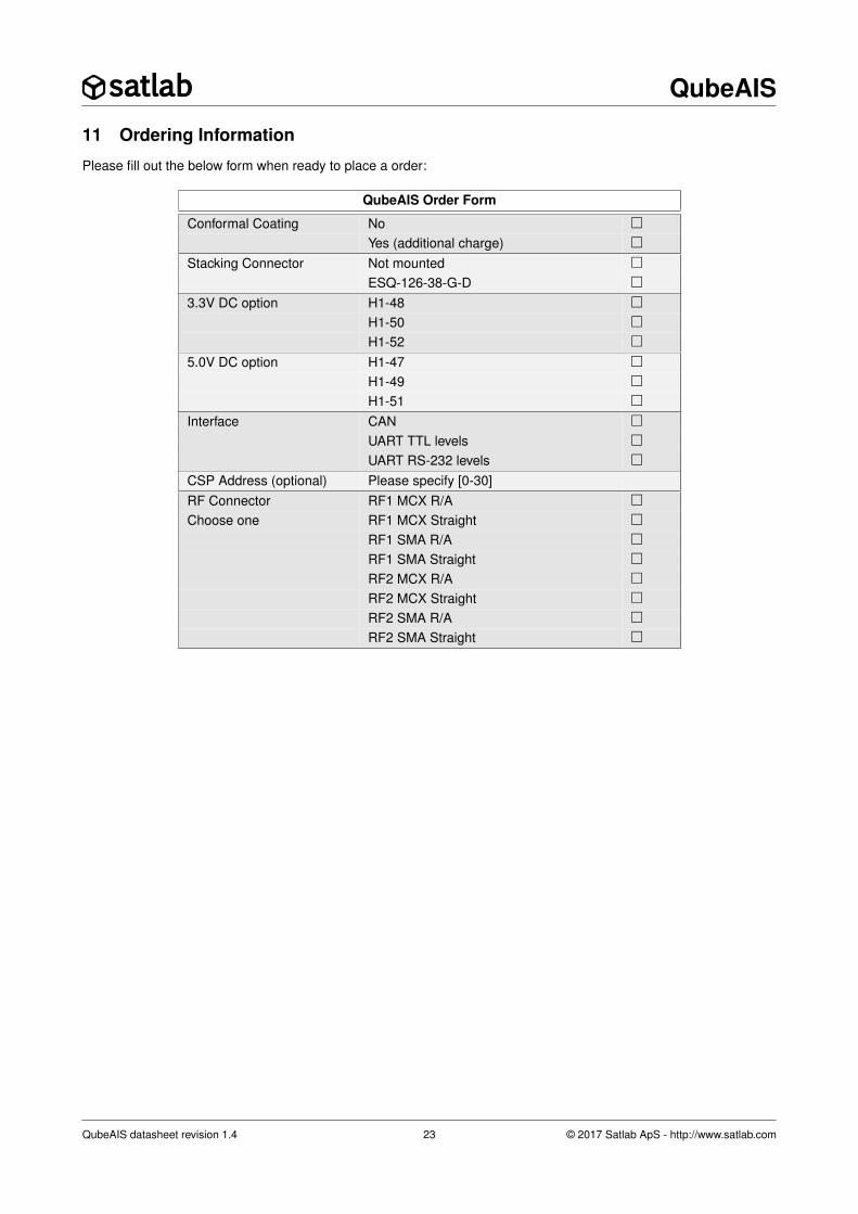
11 Ordering Information
Please fill out the below form when ready to place a order:
QubeAIS Order Form
Conformal Coating No �Yes (additional charge) �
Stacking Connector Not mounted �ESQ-126-38-G-D �
3.3V DC option H1-48 �H1-50 �H1-52 �
5.0V DC option H1-47 �H1-49 �H1-51 �
Interface CAN �UART TTL levels �UART RS-232 levels �
CSP Address (optional) Please specify [0-30]RF Connector RF1 MCX R/A �Choose one RF1 MCX Straight �
RF1 SMA R/A �RF1 SMA Straight �RF2 MCX R/A �RF2 MCX Straight �RF2 SMA R/A �RF2 SMA Straight �
QubeAIS datasheet revision 1.4 23 © 2017 Satlab ApS - http://www.satlab.com
QubeAIS
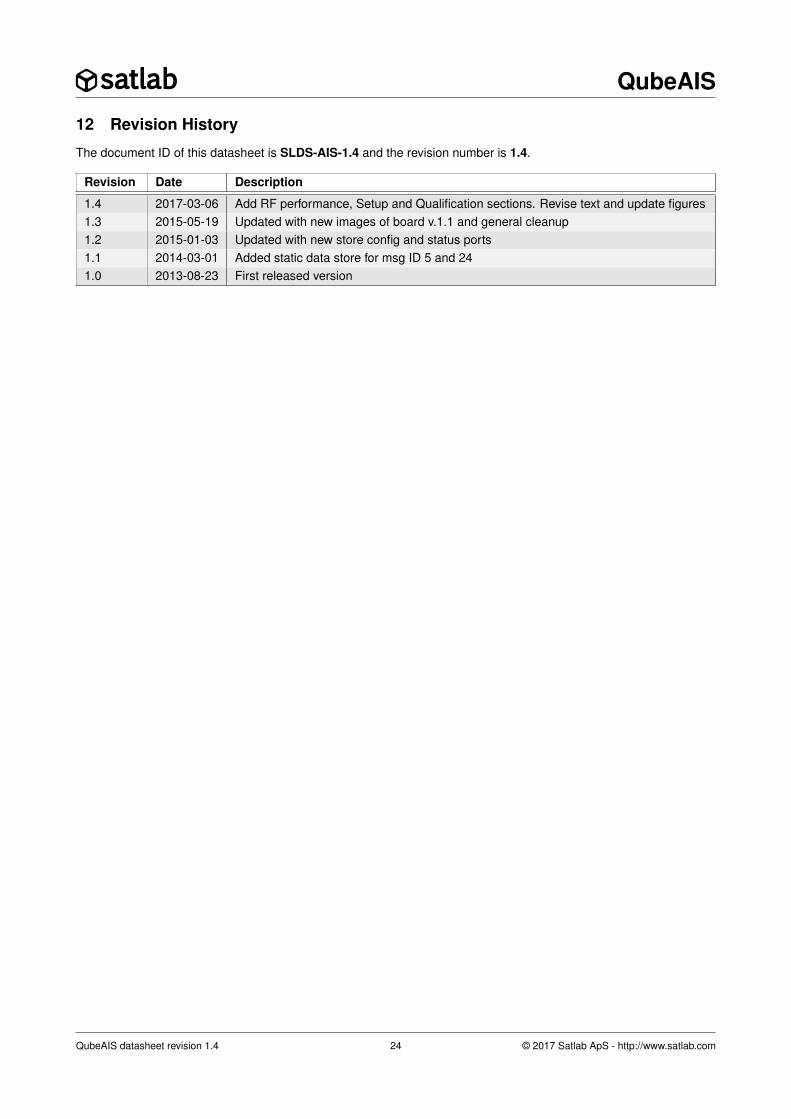
12 Revision History
The document ID of this datasheet is SLDS-AIS-1.4 and the revision number is 1.4.
Revision Date Description
1.4 2017-03-06 Add RF performance, Setup and Qualification sections. Revise text and update figures1.3 2015-05-19 Updated with new images of board v.1.1 and general cleanup1.2 2015-01-03 Updated with new store config and status ports1.1 2014-03-01 Added static data store for msg ID 5 and 241.0 2013-08-23 First released version
QubeAIS datasheet revision 1.4 24 © 2017 Satlab ApS - http://www.satlab.com
QubeAIS
Table of Contents
1 Features 1
2 Description 1
3 Electrical Details 1
4 Hardware Overview 2
5 Software Overview 35.1 Platform . . . . . . . . . . . . . . . . . . . . . . . . . . . . . . . . . . . . . . . . . . . . . . . . 35.2 AIS Loader . . . . . . . . . . . . . . . . . . . . . . . . . . . . . . . . . . . . . . . . . . . . . . . 35.3 AIS Application . . . . . . . . . . . . . . . . . . . . . . . . . . . . . . . . . . . . . . . . . . . . . 3
5.3.1 Demodulator and Frame Decoder . . . . . . . . . . . . . . . . . . . . . . . . . . . . . . . 45.3.2 Message Store and Message Filter . . . . . . . . . . . . . . . . . . . . . . . . . . . . . . 5
5.4 Setup . . . . . . . . . . . . . . . . . . . . . . . . . . . . . . . . . . . . . . . . . . . . . . . . . 7
6 Receiver Performance 8
7 Software Interface Description 107.1 Configuration and Status Interface . . . . . . . . . . . . . . . . . . . . . . . . . . . . . . . . . . . 11
7.1.1 AIS PORT STATUS . . . . . . . . . . . . . . . . . . . . . . . . . . . . . . . . . . . . . . 117.1.2 AIS PORT MODE . . . . . . . . . . . . . . . . . . . . . . . . . . . . . . . . . . . . . . . 117.1.3 AIS PORT AIS RX STATUS . . . . . . . . . . . . . . . . . . . . . . . . . . . . . . . . . . 127.1.4 AIS PORT CONFIG . . . . . . . . . . . . . . . . . . . . . . . . . . . . . . . . . . . . . . 127.1.5 AIS PORT TIME CONFIG . . . . . . . . . . . . . . . . . . . . . . . . . . . . . . . . . . 137.1.6 AIS PORT CHANNEL CONFIG . . . . . . . . . . . . . . . . . . . . . . . . . . . . . . . . 147.1.7 AIS PORT DEMOD and AIS PORT DEMOD USER . . . . . . . . . . . . . . . . . . . . . 14
7.2 Message Store Interface . . . . . . . . . . . . . . . . . . . . . . . . . . . . . . . . . . . . . . . . 157.2.1 AIS PORT STORE . . . . . . . . . . . . . . . . . . . . . . . . . . . . . . . . . . . . . . 157.2.2 AIS PORT STORE SHORT . . . . . . . . . . . . . . . . . . . . . . . . . . . . . . . . . . 167.2.3 AIS PORT STORE STATIC . . . . . . . . . . . . . . . . . . . . . . . . . . . . . . . . . . 167.2.4 AIS PORT STORE CONFIG . . . . . . . . . . . . . . . . . . . . . . . . . . . . . . . . . 167.2.5 AIS PORT STORE REQUEST . . . . . . . . . . . . . . . . . . . . . . . . . . . . . . . . 17
7.3 Blob Transfer Protocol . . . . . . . . . . . . . . . . . . . . . . . . . . . . . . . . . . . . . . . . . 187.3.1 AIS PORT BTP . . . . . . . . . . . . . . . . . . . . . . . . . . . . . . . . . . . . . . . . 18
8 Hardware Interfaces 198.1 Pinout . . . . . . . . . . . . . . . . . . . . . . . . . . . . . . . . . . . . . . . . . . . . . . . . . 198.2 Electrical Levels on Pins . . . . . . . . . . . . . . . . . . . . . . . . . . . . . . . . . . . . . . . . 20
9 Qualification 219.1 Acceptance Testing . . . . . . . . . . . . . . . . . . . . . . . . . . . . . . . . . . . . . . . . . . 21
10 Board Outline 22
11 Ordering Information 23
12 Revision History 24
Table of Contents 25
QubeAIS datasheet revision 1.4 25 © 2017 Satlab ApS - http://www.satlab.com