
Software Defined Radio Commercial Handset Guidelines SDRF-04-A
104
Software Defined Radio Forum SDRF-04-A-0006-V0.00 SDR Forum ©2004 Page 1 Software Defined Radio Commercial Handset Guidelines SDRF-04-A-0006-V0.00 Approved: 25 August 2004 SDR Forum 1616 17th Street, Suite 264 Denver, CO 80202 email: [email protected]
Transcript of Software Defined Radio Commercial Handset Guidelines SDRF-04-A
Software Defined Radio Forum SDRF-04-A-0006-V0.00
SDR Forum ©2004 Page 1
Software Defined Radio
Commercial Handset Guidelines
SDRF-04-A-0006-V0.00
Approved: 25 August 2004
SDR Forum 1616 17th Street, Suite 264
Denver, CO 80202
email: [email protected]
Allan Margulies
Inserted Text
SDRF-04-S-006-V1.0.0 Formerly SDRF-04-A-0006-V0.00
Allan Margulies
Inserted Text
SDRF-04-S-006-V1.0.0 Formerly SDRF-04-A-0006-V0.00
Software Defined Radio Forum SDRF-04-A-0006-V0.00
SDR Forum ©2004 Page 2
NOTICE AND WARNING TO MEMBERS REGARDING AREAS OF DISCUSSION AMONG MEMBERS
The SDR Forum is an organization whose members include direct competitors, government and private industry, and suppliers and purchasers of goods and services. Certain communications, between and among such parties could give rise to allegations of anti-competitive conduct under US antitrust laws. Many situations could arise in which such contacts or communications could take place, even if unintentional. Because the opportunity for such anti-competitive conduct is presented, it is important for all members to avoid even the appearance of such conduct.
Therefore, it is the policy of the SDR Forum to prohibit any discussion of:
• pricing (including discounts or terms and conditions) • market shares of individual competitors • exclusion of any competitors • cross licensing • marketing policies or practices, particularly restrictions on customers, territories, or
markets • preferential pricing or sales terms • contract bidding • any particular job, bid, contract, or competitive situation
or other potentially anti-competitive subject matter, during or in connection with member meetings, steering committee meetings, board of directors meetings, or any SDR Forum activities. Members may not initiate any such discussion, and if presented with such discussion, must refuse to participate, and must stop the discussion.
The following is a description of topics that should not give rise to the foregoing concerns. This is not intended to be an exhaustive list, but a guide to permissible areas of discussion. It is permissible to discuss overall market size and conditions; the identity and characteristics of participants in markets; standards, specifications, and technical matters relating to the industry or the technology; the economic aspects of standards or technologies, including the effects on the market of adopting a standard or competitive considerations with respect to other technologies or standards; lobbying and promotion of the technology; and the business of the SDR Forum.
Any questions about the Forum’s policy or about the prohibited topics of discussion should be directed to the SDR Forum Chair, who will authorize contact with the Forum’s counsel.
Copyright August 2004 SDR Forum
Software Defined Radio Forum SDRF-04-A-0006-V0.00
SDR Forum ©2004 Page 3
DISCLAIMER
This document is published by the SDR Forum, Inc. to provide information to the industry and to organizations involved in wireless communications as well as to open dialog and discussion to solicit information. The SDR Forum reserves the right at its sole discretion to revise this document for any reason.
The SDR Forum makes no representation or warranty, express or implied, with respect to the completeness, accuracy, or utility of the document or any information or opinion contained therein. Any use or reliance on the information or opinion is at the risk of the user, and the SDR Forum shall not be liable for any damage or injury incurred by any person arising out of the completeness, accuracy, or utility of any information or opinion contained in the document.
Nothing contained herein shall be construed to confer any license or right to any intellectual property, whether or not the use of any information herein necessarily utilizes such intellectual property.
This document does not constitute an endorsement of any product or company.
The SDR Forum, Inc. All Rights Reserved
Printed August 2004
Software Defined Radio Forum SDRF-04-A-0006-V0.00
SDR Forum ©2004 Page 4
Co-Chairs of the Working Group: Mark Cummings André Krützfeldt Calinel Pasteanu Input Documents:
• TR2.1 • TNA Working Group Report • Handset Working Group Working Papers
Software Defined Radio Forum SDRF-04-A-0006-V0.00
SDR Forum ©2004 Page 5
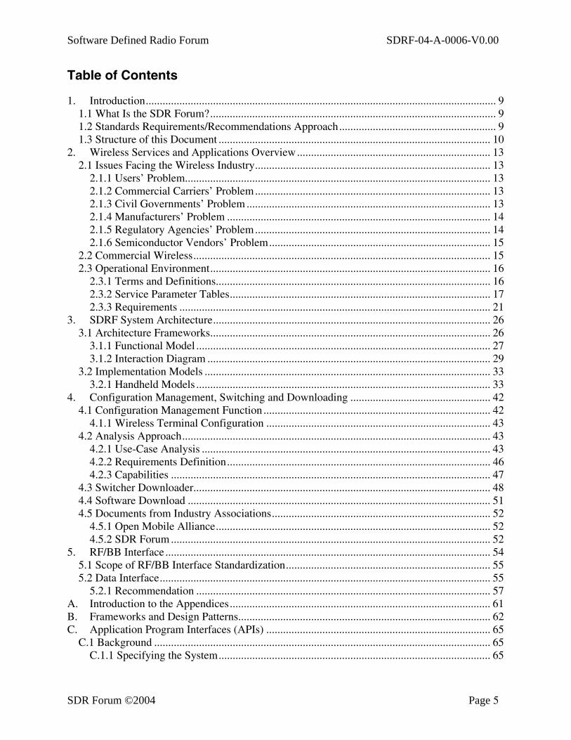
Table of Contents
1. Introduction............................................................................................................................. 9 1.1 What Is the SDR Forum?...................................................................................................... 9 1.2 Standards Requirements/Recommendations Approach........................................................ 9 1.3 Structure of this Document ................................................................................................. 10
2. Wireless Services and Applications Overview..................................................................... 13 2.1 Issues Facing the Wireless Industry.................................................................................... 13
2.1.1 Users’ Problem............................................................................................................. 13 2.1.2 Commercial Carriers’ Problem.................................................................................... 13 2.1.3 Civil Governments’ Problem ....................................................................................... 13 2.1.4 Manufacturers’ Problem .............................................................................................. 14 2.1.5 Regulatory Agencies’ Problem.................................................................................... 14 2.1.6 Semiconductor Vendors’ Problem............................................................................... 15
2.2 Commercial Wireless.......................................................................................................... 15 2.3 Operational Environment.................................................................................................... 16
2.3.1 Terms and Definitions.................................................................................................. 16 2.3.2 Service Parameter Tables............................................................................................. 17 2.3.3 Requirements ............................................................................................................... 21
3. SDRF System Architecture................................................................................................... 26 3.1 Architecture Frameworks.................................................................................................... 26
3.1.1 Functional Model ......................................................................................................... 27 3.1.2 Interaction Diagram ..................................................................................................... 29
3.2 Implementation Models ...................................................................................................... 33 3.2.1 Handheld Models ......................................................................................................... 33
4. Configuration Management, Switching and Downloading .................................................. 42 4.1 Configuration Management Function ................................................................................. 42
4.1.1 Wireless Terminal Configuration ................................................................................ 43 4.2 Analysis Approach.............................................................................................................. 43
4.2.1 Use-Case Analysis ....................................................................................................... 43 4.2.2 Requirements Definition.............................................................................................. 46 4.2.3 Capabilities .................................................................................................................. 47
4.3 Switcher Downloader.......................................................................................................... 48 4.4 Software Download ............................................................................................................ 51 4.5 Documents from Industry Associations.............................................................................. 52
4.5.1 Open Mobile Alliance.................................................................................................. 52 4.5.2 SDR Forum .................................................................................................................. 52
5. RF/BB Interface .................................................................................................................... 54 5.1 Scope of RF/BB Interface Standardization......................................................................... 55 5.2 Data Interface...................................................................................................................... 55
5.2.1 Recommendation ......................................................................................................... 57 A. Introduction to the Appendices............................................................................................. 61 B. Frameworks and Design Patterns.......................................................................................... 62 C. Application Program Interfaces (APIs) ................................................................................ 65
C.1 Background ........................................................................................................................ 65 C.1.1 Specifying the System................................................................................................. 65
Software Defined Radio Forum SDRF-04-A-0006-V0.00
SDR Forum ©2004 Page 6
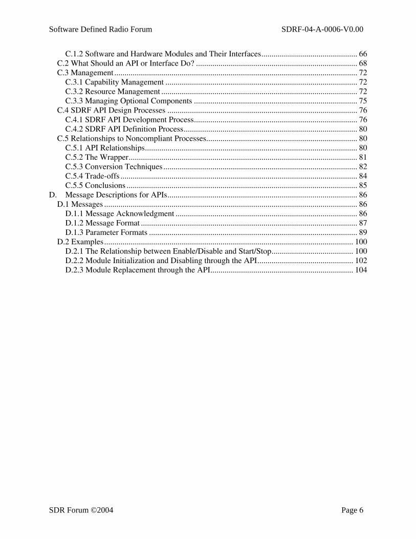
C.1.2 Software and Hardware Modules and Their Interfaces............................................... 66 C.2 What Should an API or Interface Do? ............................................................................... 68 C.3 Management ....................................................................................................................... 72
C.3.1 Capability Management .............................................................................................. 72 C.3.2 Resource Management ................................................................................................ 72 C.3.3 Managing Optional Components ................................................................................ 75
C.4 SDRF API Design Processes ............................................................................................. 76 C.4.1 SDRF API Development Process................................................................................ 76 C.4.2 SDRF API Definition Process..................................................................................... 80
C.5 Relationships to Noncompliant Processes.......................................................................... 80 C.5.1 API Relationships........................................................................................................ 80 C.5.2 The Wrapper................................................................................................................ 81 C.5.3 Conversion Techniques ............................................................................................... 82 C.5.4 Trade-offs .................................................................................................................... 84 C.5.5 Conclusions ................................................................................................................. 85
D. Message Descriptions for APIs............................................................................................. 86 D.1 Messages ............................................................................................................................ 86
D.1.1 Message Acknowledgment ......................................................................................... 86 D.1.2 Message Format .......................................................................................................... 87 D.1.3 Parameter Formats ...................................................................................................... 89
D.2 Examples.......................................................................................................................... 100 D.2.1 The Relationship between Enable/Disable and Start/Stop........................................ 100 D.2.2 Module Initialization and Disabling through the API............................................... 102 D.2.3 Module Replacement through the API...................................................................... 104
Software Defined Radio Forum SDRF-04-A-0006-V0.00
SDR Forum ©2004 Page 7
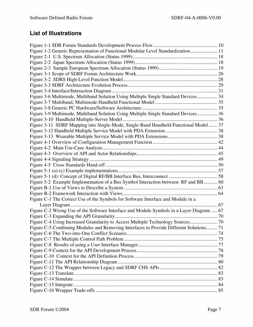
List of Illustrations Figure 1-1 SDR Forum Standards Development Process Flow.................................................... 10 Figure 1-2 Generic Representation of Functional Modular Level Standardization...................... 11 Figure 2-1 U.S. Spectrum Allocation (Status 1999) .................................................................... 18 Figure 2-2 Japan Spectrum Allocation (Status 1999) .................................................................. 18 Figure 2-3 Sample European Spectrum Allocation (Status 1999)............................................... 19 Figure 3-1 Scope of SDRF Forum Architecture Work................................................................. 26 Figure 3-2 SDRS High-Level Function Model............................................................................ 28 Figure 3-3 SDRF Architecture Evolution Process........................................................................ 29 Figure 3-4 Interface/Interaction Diagram ..................................................................................... 31 Figure 3-6 Multimode, Multiband Solution Using Multiple Single Standard Devices ................ 34 Figure 3-7 Multiband, Multimode Handheld Functional Model .................................................. 35 Figure 3-8 Generic PC Hardware/Software Architecture............................................................. 35 Figure 3-9 Multimode, Multiband Solution Using Multiple Single Standard Devices ................ 36 Figure 3-10 Handheld Multiple-Server Model ............................................................................ 36 Figure 3-11 SDRF Mapping into Single-Mode, Single-Band Handheld Functional Model ....... 37 Figure 3-12 Handheld Multiple Service Model with PDA Extension.......................................... 38 Figure 3-13 Wearable Multiple Service Model with PDA Extensions........................................ 38 Figure 4-1 Overview of Configuration Management Function .................................................... 42 Figure 4-2 Main Use-Case Analysis ............................................................................................ 44 Figure 4-3 Overview of API and Actor Relationships................................................................. 45 Figure 4-4 Signaling Strategy ....................................................................................................... 49 Figure 4-5 Cross Standards Hand-off .......................................................................................... 50 Figure 5-1 (a)-(c) Example implementations................................................................................ 57 Figure 5-1 (d): Concept of Digital RF/BB Interface Bus, Interconnect ....................................... 58 Figure 5-2 Example Implementation of a Bus Symbol Interaction between RF and BB........... 60 Figure B-1 Use of Views to Describe a System ........................................................................... 63 Figure B-2 Framework Interaction with Views ............................................................................ 64 Figure C-1 The Correct Use of the Symbols for Software Interface and Module in a
Layer Diagram ...................................................................................................................... 67 Figure C-2 Wrong Use of the Software Interface and Module Symbols in a Layer Diagram ..... 67 Figure C-3 Expanding the API Granularity .................................................................................. 70 Figure C-4 Using Increased Granularity to Access Multiple Technology Sources...................... 70 Figure C-5 Combining Modules and Removing Interfaces to Provide Different Solutions......... 71 Figure C-6 The Two-into-One Conflict Scenario.. ....................................................................... 74 Figure C-7 The Multiple Control Path Problem ........................................................................... 75 Figure C-8 Results of using a User Interface Manager................................................................ 77 Figure C-9 Context for the API Development Process................................................................. 78 Figure C-10 Context for the API Definition Process................................................................... 79 Figure C-11 The API Relationship Diagram ................................................................................ 80 Figure C-12 The Wrapper between Legacy and SDRF CHS APIs .............................................. 82 Figure C-13 Translate ................................................................................................................... 83 Figure C-14 Simulate.................................................................................................................... 83 Figure C-15 Integrate.................................................................................................................... 84 Figure C-16 Wrapper Trade-offs .................................................................................................. 85
Software Defined Radio Forum SDRF-04-A-0006-V0.00
SDR Forum ©2004 Page 8
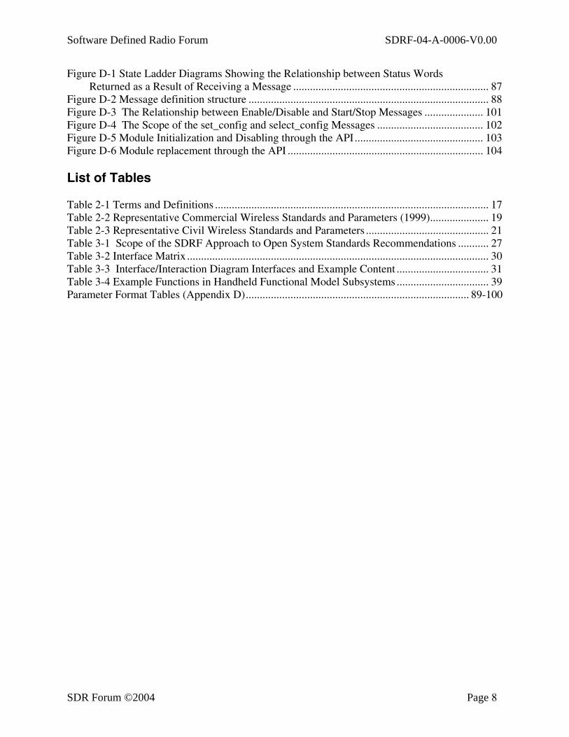
Figure D-1 State Ladder Diagrams Showing the Relationship between Status Words Returned as a Result of Receiving a Message ...................................................................... 87
Figure D-2 Message definition structure ...................................................................................... 88 Figure D-3 The Relationship between Enable/Disable and Start/Stop Messages ..................... 101 Figure D-4 The Scope of the set_config and select_config Messages ...................................... 102 Figure D-5 Module Initialization and Disabling through the API.............................................. 103 Figure D-6 Module replacement through the API ...................................................................... 104 List of Tables Table 2-1 Terms and Definitions .................................................................................................. 17 Table 2-2 Representative Commercial Wireless Standards and Parameters (1999)..................... 19 Table 2-3 Representative Civil Wireless Standards and Parameters ............................................ 21 Table 3-1 Scope of the SDRF Approach to Open System Standards Recommendations ........... 27 Table 3-2 Interface Matrix ............................................................................................................ 30 Table 3-3 Interface/Interaction Diagram Interfaces and Example Content ................................. 31 Table 3-4 Example Functions in Handheld Functional Model Subsystems ................................. 39 Parameter Format Tables (Appendix D)................................................................................ 89-100
Software Defined Radio Forum SDRF-04-A-0006-V0.00
SDR Forum ©2004 Page 9
1. Introduction
1.1 What Is the SDR Forum? The Software Defined Radio Forum (SDR Forum, or SDRF) is an open, non-profit corporation dedicated to supporting the development, deployment, and use of open architectures for advanced wireless systems.
Primary objectives of the Forum are:
• To enable seamless integration of capabilities across diverse networks, in an environment of multiple standards and solutions,
• To accelerate proliferation of software-definable radio systems, • To advance adoption of open architectures for wireless systems, • To promote “multiple capability and multiple mission” system flexibility, and • To ensure accommodation of current and future user needs in the areas of voice, data,
messaging, image, multimedia, etc.
Forum membership comprises an international mix of business and technical decision makers, planners, policy makers, and program managers from a broad range of organizations that share a common view of advanced wireless networking systems evolution. Specifically, the SDR Forum membership includes:
• Service providers • Equipment manufacturers • Component manufacturers/providers • Hardware and software developers • System integrators • Government and military1 • Standards development organizations • Industry associations/forums • Academic and research organizations
1.2 Standards Requirements/Recommendations Approach The SDR Forum is pursuing its goals through the efforts of three core committees, the Markets Committee, the Technical Committee, and the Regulatory Committee. The Markets Committee is chartered with promoting Forum activities and the development of SDR-concept-based market forecast material. The Technical Committee is chartered with specifications development and market projection. The Regulatory Committee is chartered with tracking, coordinating, harmonizing, and developing recommendations concerning regulations relevant to SDR-concept-based system and product deployment, and responding to requests for information (RFIs).
The Forum seeks global harmonization of SDR concepts. Efforts are being coordinated with international industry associations, forums, and standards development organizations (SDOs). The Forum operates under a requirements, rather than technology-driven, philosophy, although it
1This area is not discussed in this document, please refer to the Systems Interface Group documents.

Software Defined Radio Forum SDRF-04-A-0006-V0.00
SDR Forum ©2004 Page 10
is understood that the two areas must be considered jointly. Two broad categories of wireless issues, generally defined as user need and technical concern, are recognized. Software defined radios (SDRs), which utilize conventional and innovative approaches to high-speed digital processing, RF processing, antennas, etc. are the underlying technology holding promise for addressing both issues.
The basic process followed by the Forum is to translate the end-user needs into standards requirements/recommendations for action by standards development organizations (SDOs). If the Forum cannot identify an SDO for the issue, the Forum will develop standards recommendations for release to the industry.
Figure 1-1 shows the basic process flow.
Figure 1-1 SDR Forum Standards Development Process Flow
1.3 Structure of this Document This document starts by describing the SDR requirements for handsets and other mobile wireless devices, building the background, top-level conceptual descriptions, and functional requirements that form the basis for the recommendations that follow. Key to this approach is the modularization of the functions that reflect a balance between a coarse division of functional

Software Defined Radio Forum SDRF-04-A-0006-V0.00
SDR Forum ©2004 Page 11
modularity that may be too general to achieve an open architecture and too granular such that every function of the specification is described.
After the background material, the document develops the general reference model for the SDRF architecture. The primary functional modules are the radio frequency (RF) section, modem, antenna, information security, input/output (I/O), environment adaptation, and control. These functional modules may be interconnected to collectively function as a whole wireless unit. The recommendations that follow take the form of specific requirements for the interface between functional modules and a description of the transfer characteristics of each module.
M oduleA
M oduleB
M oduleC
M oduleA
M oduleB
M oduleC
Com m on In frastructure
Std
StdStd
Std
Std
M odule - to - M odule S tandard
M odule - to - B us S tandard
M odule D
Figure 1-2 Generic Representation of Functional Modular Level Standardization
Figure 1-2 is a generic representation of a functional modular-level standardization approach. The solution may take the form of either a module-to-module (hardware or software) interface or a module-to-bus standard. The goal is to provide a common interface between modules without restricting and inhibiting the innovation that can be achieved within them. It is necessary that mandatory functions are provided and interface requirements met.
Interfaces for a module are separated into an information interface and a control interface. In both cases, these interfaces are bi-directional in nature. There may be a separate recommendation for each of these two interfaces. An interface matrix identifies the modules and module-to-module elements that require some level of description or standardization. The modules themselves require a description of the functionality that must take place within that module but without specifying what methodology or technology must be used to accomplish it as long as there is compliance with the interface requirements. The module-to-module interfaces will require a standard format for the exchange of information as well as a standard format for the exchange of control.
Software Defined Radio Forum SDRF-04-A-0006-V0.00
SDR Forum ©2004 Page 12
The main document concludes with detailed recommendations for RF/BB (baseband) interfaces within a handset.
Following the main document are a set of appendices. Appendix A is an introduction to the other appendices. Appendix B describes how “views” were used in the process of conceptualizing the material contained in these recommendations. Appendix C describes how APIs are conceptualized as interfaces between modules. Appendix D describes message formats for implementing these recommendations, including “capability exchange.”
Software Defined Radio Forum SDRF-04-A-0006-V0.00
SDR Forum ©2004 Page 13
2. Wireless Services and Applications Overview
This section reviews the typical usage application environments that provide the background for the technical analysis and standards recommendations that follow. System context diagrams provide a means to understand the scope and limits of the SDR Forum standards recommendations focus. The service parameter tables present the type of technical parameters that must be addressed when developing architectures.
To help understand the range of applications that face the SDR Forum, it is useful to look at some examples of problems faced by the various wireless communications users and suppliers in providing the motivation for a universal, software defined device to allow seamless use of a range of services.
2.1 Issues Facing the Wireless Industry
2.1.1 Users’ Problem The users’ problem is one of connectivity and a growing number of incompatible Air Interface Standards (AISs) as well as information filtering. At their desks, users have email, telephones, personal computers, and wideband connectivity to internal backbones and external services. As they leave their offices, they have to rely on pagers for notification and cellular or Personal Communications Systems (PCS) phones for contact. Both of these devices, however, have limited access areas and specific protocols.
Users also have separate palmtop devices for multimedia information capture, storage, and display; these devices incorporate substantial computational power. Software programmable radio technology offers its users, whether at home, in their offices, or on the road, an opportunity to have seamless connectivity with their data sources, including a filtering capability so they receive the information they need but are not overwhelmed by broadband data when operating in a narrowband environment.
2.1.2 Commercial Carriers’ Problem The general commercial problem is the need to integrate service portfolios and avoid forklift upgrades. Carriers with multiple service types and multiple standards want to be able to integrate their service portfolios. Carriers with a single service, single technology strategy, however, are being forced into multiple service portfolios by (1) mergers and acquisitions, (2) international operations, and (3) international roaming. In addition, in Europe and Japan, capacity problems are creating the need for multimode, multiband solutions.
2.1.3 Civil Governments’ Problem An urgent need exists for emergency service agencies and law enforcement agencies to intercommunicate. Currently, city, state, and national agencies supporting a national emergency have multiple services and systems that cannot intercommunicate readily. Interagency communications usually requires an exchange of assets to support these temporary situations. Likewise, civil aviation requires a wide variety of communications and means of information transfer to support safe air travel and airport management. The civil aviation authorities would like to be able to upgrade systems in the field as new air interfaces are developed. This fosters
Software Defined Radio Forum SDRF-04-A-0006-V0.00
SDR Forum ©2004 Page 14
the need for long system life cycles as well as “future proofing” to facilitate the expansion of the systems to take advantage of new technologies as they become available and to upgrade at a reasonable cost. The capability to reduce the number and types of devices by utilizing adaptive technologies also is needed.
2.1.4 Manufacturers’ Problem Manufacturers are seeking ways to improve time to market, increase flexibility to add new services and features, reduce the number of fundamental designs, increase the production volume per design, simplify testing, and allow for upgradeability in the field. The flexibility associated with software defined radios and well-structured interfaces that anticipate the features required for new applications overlaid onto existing services allows equipment vendors to support customer feature requests for equipment that is already fielded. A reduced number of fundamental designs allows the production volume of each fundamental design to be higher, and allows larger component volume purchases. This then leads to more cost-effective production techniques and allows insertion of new features during production. Simplified testing/validation thus arises with fewer designs to be validated.
2.1.5 Regulatory Agencies’ Problem The most pressing regulatory issue is how to meet the demand from the communications industry for additional spectrum, which is currently unavailable. The governments of the industrialized nations in general have established regulatory agencies to manage the electromagnetic spectrum. They accomplish this task through rule-making proceedings that classify services, provide specified RF spectrum for various types of communications links, and specify technical parameters for operation. Historically, as communications needs increase, the need for additional spectrum has been met by opening up new bands at higher and higher frequencies, and technology is then developed to utilize these higher bands.
To provide for the increasing demand for communications services, current spectrum management policy has been geared to auction spectrum licenses to the maximum extent possible. Tied to this policy is the concept of minimal in-band technical requirements. This allows the licenseholder complete freedom to utilize the most flexible and best technology available to maximize the communications links at the holder’s disposal. This regulatory policy is designed to generate a favorable climate for technology development by maximizing the communications link per cost formula and increasing the efficiency of spectrum utilization.
In summary, due to the lack of available spectrum for communications purposes, the most critical issue for regulatory agencies in the industrialized nations is to develop policies that increase the efficiency of spectrum usage while reducing interference and increasing the ease of frequency refarming. To meet the ever-increasing demand for communications links, technology breakthroughs are needed that can economically increase the efficiency of spectrum utilization. These breakthroughs are likely to occur through reconfigurable radios that maintain electromagnetic compatibility with existing systems, permit frequency reuse, and allow flexibility for future technology upgrades.
Sample spectrum allocations for the United States, Japan, and Europe for the year 1999 are presented in Section 2.3, Operational Environment.
Software Defined Radio Forum SDRF-04-A-0006-V0.00
SDR Forum ©2004 Page 15
2.1.6 Semiconductor Vendors’ Problem As semiconductor vendors view the silicon chip opportunity space, players in the market share one concern: “How will we keep our fabrications facility full?” Coupled with this question is the subtle paradigm change in the industry. Historically, the belief was that silicon chip development was driven by the requirements of the systems. The silicon chip was viewed as a way to lower cost, to enhance further integration, and to drive products into new markets. In the current era, as less than 0.25-micron process technologies become commonplace, the paradigm is “systems because of silicon chips.” Systems that were considered inconceivable two years ago are commercial, single-chip products today.
These two issues together are putting tremendous business pressures on semiconductor vendors. To keep fabrications full, they focus on industries, which require very large silicon chip volumes. For this reason, the wireless industry is the focus of almost every major semiconductor vendor, due to its tremendous volumes. This picture simply whets the appetite of every silicon chip vendor hungry to move high-margin CMOS silicon wafers. Moreover, the profit margins per wafer are becoming increasingly more important. This value is derived from intellectual property in the form of hardware and software.
Playing directly against this is the fact that to succeed in the wireless industry and recognize the full advantage of the “volumes of silicon chips,” semiconductor vendors must be able to offer silicon chip solutions that support the multitude of standards across different consumer markets and geographical regions. These solutions must appear on the market at particular power, performance, and at price points dictated by the end-product market dynamics. Historically, this requires the semiconductor vendor to develop application-specific signal-processing solutions for every standard, ranging across IS-136, GSM, UMTS, DECT, PHS, PDC, IS-95 CDMA, WCDMA, and ISM-band cordless systems. Currently, this is an expensive proposition, with the cost dominated by the need to create a customized semiconductor solution from scratch for every standard. Moreover, this fixed cost creates a limit on the number of design starts the vendor can support, irrespective of fabrication facility capacity.
The availability of a software defined radio is fundamentally changing this design problem, and, as a result, the business equation. The ability to reduce time on the “design start” process, reduce the number of fundamental designs, significantly reduce silicon manufacturing and test costs, and significantly increase the wafer production volumes per design start creates a business environment in which semiconductor vendors can address multiple standards in an economically feasible manner. Software configurability is recognized as a key enabler for this capability.
2.2 Commercial Wireless Commercial wireless markets, which include services such as cellular, PCS, paging, wireless data services (e.g., packet radio), cordless phones, wireless local area networks (WLANs), GPS, satellite, and so forth, are growing rapidly. Users value integrated operations in such combinations as cellular, paging, wireless data, and even cordless. Within different services, however, multiple standards exist. The current proliferation of incompatible mobile standards is creating a market environment that will demand software radio technology and standards to facilitate roaming.

Software Defined Radio Forum SDRF-04-A-0006-V0.00
SDR Forum ©2004 Page 16
2.3 Operational Environment This section provides an overview of example wireless services, supporting standards, and critical defining parameters. The goal of this section is to provide the understanding needed to identify wireless services and standards recommendations according to anticipated capabilities of various classes of software radio platforms.
Table 2-1 defines the different categories and types of recommendations and provides examples of each. These include terms to be defined within a framework for which these guidelines may serve both SDRF’s vision as a software radio, as well as future developments. Targeted future possibilities include devices and systems that are functionally defined through the digital signal processing, and the software that these devices feature, within an architecture that allows for multiple standards and information transfer services. Near-term applications may include combinations of cellular, pagers, cordless telephones, GPS, and WLANS. The ability to also include a Low Earth Orbiting (LEO) satellite and International Maritime Satellite (INMARSAT)-type satellite radio function, along with cellular and other services, could also be envisioned. Further growth to include data networking and the possibility of other services open up more applications than can currently be categorized usefully. Thus, the categories of applications provide some flexibility and abstraction, so that further applications may be defined while fitting within the same overall framework.
Examples of actual application recommendations appear in a set of tables defined by the standards they fit. Other items in Table 2.1 (e.g., simultaneity) are of interest for SDRF applications. The definitions serve as example points of reference for future application descriptions in SDRF. Further work in identifying SDRF applications will be carried out as part of the Technical Working Group’s functions.
The recommendations include applications and the functional parameters associated with those applications. In many cases, parameters are included by reference to the standard (or other reference) with which they are associated. The tables are organized around the major categories, and the markets. A set of tables for each case provides the parameters, applicable standards recommendations, and standards references.
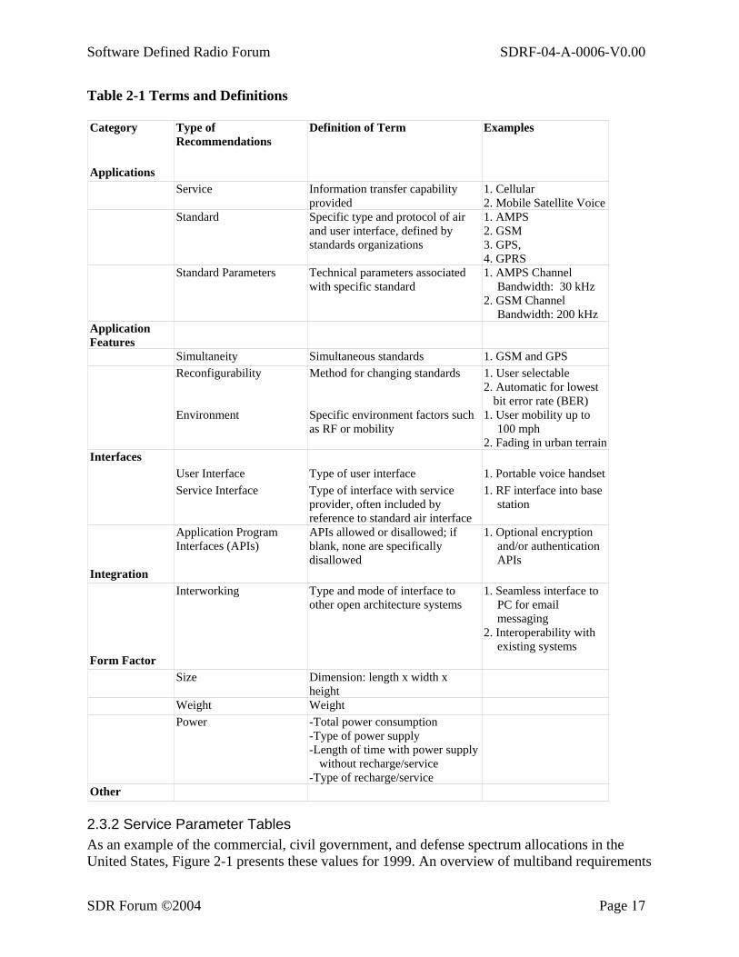
2.3.1 Terms and Definitions Table 2-1 defines the terms used. Recommendations are defined by class and type. Examples are shown only to clarify their use, and in no way imply that these are the only types to be defined, nor necessarily the most important ones. Recommendations are categorized as those pertaining to applications, interfaces, integration, and form factor.
Software Defined Radio Forum SDRF-04-A-0006-V0.00
SDR Forum ©2004 Page 17
Table 2-1 Terms and Definitions
Category Type of Recommendations
Definition of Term Examples
Applications Service Information transfer capability
provided 1. Cellular 2. Mobile Satellite Voice
Standard Specific type and protocol of air and user interface, defined by standards organizations
1. AMPS 2. GSM 3. GPS, 4. GPRS
Standard Parameters Technical parameters associated with specific standard
1. AMPS Channel Bandwidth: 30 kHz
2. GSM Channel Bandwidth: 200 kHz
Application Features
Simultaneity Simultaneous standards 1. GSM and GPS Reconfigurability Method for changing standards 1. User selectable
2. Automatic for lowest bit error rate (BER)
Environment Specific environment factors such as RF or mobility
1. User mobility up to 100 mph
2. Fading in urban terrain Interfaces User Interface Type of user interface 1. Portable voice handset
Service Interface Type of interface with service provider, often included by reference to standard air interface
1. RF interface into base station
Application Program Interfaces (APIs)
APIs allowed or disallowed; if blank, none are specifically disallowed
1. Optional encryption and/or authentication APIs
Integration Interworking Type and mode of interface to
other open architecture systems 1. Seamless interface to
PC for email messaging
2. Interoperability with existing systems
Form Factor Size Dimension: length x width x
height
Weight Weight Power -Total power consumption
-Type of power supply -Length of time with power supply
without recharge/service -Type of recharge/service
Other
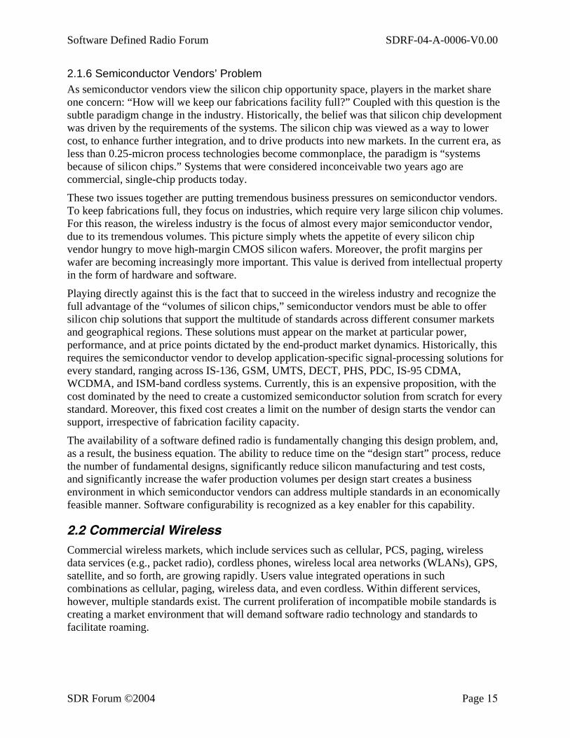
2.3.2 Service Parameter Tables As an example of the commercial, civil government, and defense spectrum allocations in the United States, Figure 2-1 presents these values for 1999. An overview of multiband requirements
Software Defined Radio Forum SDRF-04-A-0006-V0.00
SDR Forum ©2004 Page 18
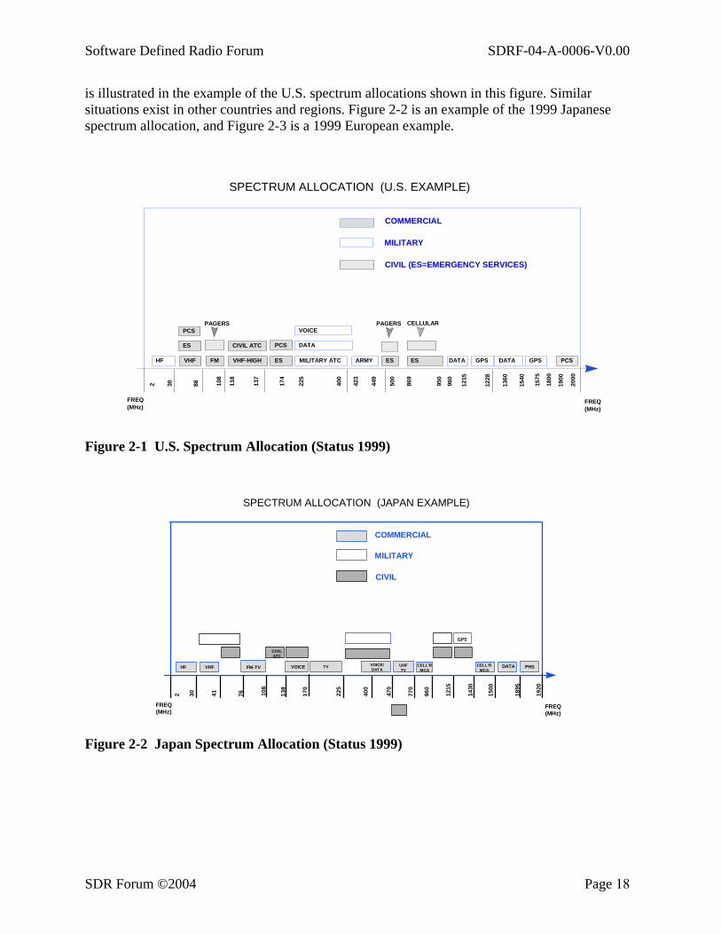
is illustrated in the example of the U.S. spectrum allocations shown in this figure. Similar situations exist in other countries and regions. Figure 2-2 is an example of the 1999 Japanese spectrum allocation, and Figure 2-3 is a 1999 European example.
HF
PCS ES VHF FM
CIVIL ATC VHF-HIGH
PCS ES MILITARY ATC
DATA
VOICE
ARMY ES ES DATA GPS DATA GPS PCS
PAGERS CELLULARPAGERS
2 30
88
108
118
137
174
225
400
423
449
500
869
950
960
1215
1228
13
60
1540
15
75
1800
19
00
2000
FREQ (MHz) FREQ
(MHz)
MILITARY
CIVIL (ES=EMERGENCY SERVICES)
COMMERCIAL
SPECTRUM ALLOCATION (U.S. EXAMPLE)
Figure 2-1 U.S. Spectrum Allocation (Status 1999)
HF VHF
CIVIL ATC
FM-TV VOICE VOICE/ DATA
GPS
DATA PHS
2 30 41 76 108
138
170
225
400
470
770
960
1215
1430
1500
1895
1920
FREQ(MHz)
FREQ(MHz)
MILITARY
CIVIL
COMMERCIAL
SPECTRUM ALLOCATION (JAPAN EXAMPLE)
TV UHFTV
CELL’RMCA
CELL’RMCA
Figure 2-2 Japan Spectrum Allocation (Status 1999)
Software Defined Radio Forum SDRF-04-A-0006-V0.00
SDR Forum ©2004 Page 19
MILITARY
CIVIL (ES=EMERGENCY SERVICES)
COMMERCIAL
SPECTRUM ALLOCATION (EUROPEAN EXAMPLE)
2200
2110
2020
1900
1710
1660
1610
1559
1525
1492
1452
1240
1215960
935
890
862
470
450
420
335
328
169
108
87.5
FPLMTSPCSGPSPCSBCST
DAB
GPSCIVIL ATCPCSBCST
TV
PMRPMRCIVIL ATCESPagerFMVHFHF
FREQ(MHz)
FREQ(MHz)
ES
2 (1
.5)
Cellular Cellular
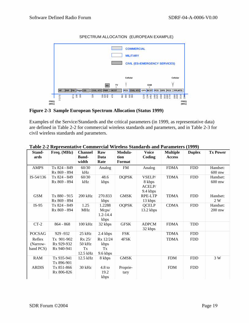
Figure 2-3 Sample European Spectrum Allocation (Status 1999) Examples of the Service/Standards and the critical parameters (in 1999, as representative data) are defined in Table 2-2 for commercial wireless standards and parameters, and in Table 2-3 for civil wireless standards and parameters.
Table 2-2 Representative Commercial Wireless Standards and Parameters (1999)
Stand-ards
Freq. (MHz) Channel Band-width
Raw Data Rate
Modula-tion Format
Voice Coding
Multiple Access
Duplex Tx Power
AMPS Tx 824 - 849 Rx 869 - 894
60/30 kHz
Analog FM Analog FDMA FDD Handset: 600 mw
IS-54/136 Tx 824 - 849 Rx 869 - 894
60/30 kHz
48.6 kbps
DQPSK VSELP/ 8 kbps
ACELP/ 9.4 kbps
TDMA FDD Handset: 600 mw
GSM Tx 880 - 915 Rx 869 - 894
200 kHz 270.833 kbps
GMSK RPE-LTP 13 kbps
TDMA FDD Handset: 2 W
IS-95 Tx 824 - 849 Rx 869 - 894
1.25 MHz
1.2288 Mcps/
1.2-14.4 kbps
OQPSK QCELP 13.2 kbps
CDMA FDD Handset: 200 mw
CT-2 864 - 868 100 kHz 32 kbps GFSK ADPCM 32 kbps
FDMA TDD
POCSAG 929 -932 25 kHz 2.4 kbps FSK TDMA FDD Reflex
(Narrow-band PCS)
Tx 901-902 Rx 929-932 Rx 940-941
Rx 25/ 50 kHz
Tx 12.5 kHz
Rx 12/24 kbps Tx
9.6 kbps
4FSK TDMA FDD
RAM Tx 935-941 Tx 896-901
12.5 kHz 8 kbps GMSK FDM FDD 3 W
ARDIS Tx 851-866 Rx 806-826
30 kHz 4.8 to 19.2 kbps
Proprie-tary
FDM FDD

Software Defined Radio Forum SDRF-04-A-0006-V0.00
SDR Forum ©2004 Page 20
Stand-ards
Freq. (MHz) Channel Band-width
Raw Data Rate
Modula-tion Format
Voice Coding
Multiple Access
Duplex Tx Power
ISM Band (U.S.)
902 - 928 MHz
2.4 -2.485 GHz
5.75-5.85 GHz
wide variety
No Standard
WLAN, WPBX cordless phone DS-1 links
FCC Part 15
Spread Spectrum DS & FH
Typically FDMA
Typically
FDD
1 W (USA)
DECT 1880-1900 1.726 MHz
1.152 Mbps
GFSK ADPCM 32 kbps
TDMA TDD 250 mW
DCS 1800 Tx 1805 - 1880
Rx 1710 - 1785
200 kHz 270.833 kbps
GMSK RPE-LTP 13 kbps
TDMA FDD 1W
PCS 1900 1800 - 1950 200 kHz 270.832 kbps
GMSK CELP 13 kbps
TDMA FDD Handset: 600 mW
IS-136+ 1800 - 1950 6030 kHz
48.6 kbps
DQPSK ACELP 7.4 kbps
TDMA FDD Handset: 600 mW
IS-95+ 1800 - 1950 1.25 MHz
1.2288 Mbps
OQPSK CDMA FDD Handset: 200 mW
IS-661 Omni-point
1800 - 1950 2.5 MHz FDMA/ TDMA/ CDMA
TDD Handset: 600 mW
PACS 1930-1990 1850-1910
300 kHz 64 kbps π/4 OQPSK
ADPCM 32 kbps
TDMA FDD
PDC Tx 925-956, 1477-1501
Rx 810-818, 870-883,
1429-1453
50/25 kHz
42 kbps π/4 OQPSK
PSI-CELP 3.45 kbps
TDMA FDD Handset: 600 mW
PHS 1895-1918 300 kHz 384 kbps π/4 OQPSK
ADPCM 32 kbps
TDMA TDD Handset: 10 mW (Avg.)
80 mW (Burst)
IRIDIUM (mobile
user segment)
1616 - 1626.5
3,840 channels total (48 cells
per satellite,
80 channels per cell
on average)
50 Kbps burst to provide voice at 4.8 Kbps and data
at 2.4 Kbps
QPSK FDMA/ TDMA
FDD

Software Defined Radio Forum SDRF-04-A-0006-V0.00
SDR Forum ©2004 Page 21
Table 2-3 Representative Civil Wireless Standards and Parameters
Standards Freq. (MHz)
Channel Spacing
Raw Data Rate
Modulation Format
Multiple Access
Duplex Tx Power
VHF Digital Link
117.975-137
25 kHz 37.5 kHz D8PSK TDMA HD
VHF Air/Ground
117.975 - 137.
8.33 kHz/ 25 kHz
Analog AM-DSB FDM HD
VHF Air/Ground
108.0 - 117.975
25 kHz Analog AM-DSB FDM Simplex
Maritime VHF
156-165(US) 174(EU)
5 kHz Analog FM ±5kHz FDM HD
APCO-25 FCC Part 90
12.5/6.25 kHz
9.6 kbps APSK/C4FM FDM FD
2.3.3 Requirements
2.3.3.1. Handheld Requirements
Handheld system solutions are driven by a set of requirements that differentiate them from mobile and fixed systems. The most notable of these are power, cost, volume, and weight. Handheld solutions have to be in a form factor that is convenient for a person to hold and carry and has the longest possible battery life. Handheld systems are battery powered, using transmit power ranging from 1 mW to 1 W (limited by health concerns). Another factor related to power management and form factor is heat dissipation. There is no space for cooling devices such as fans and not enough battery power is available to afford solutions that do not themselves generate large amounts of heat. Another aspect of handheld systems is the focus on cost. The number of units fielded is relatively large in proportion to other network components, so the focus on cost minimization is significant.
Handset form factors are fairly well established, Currently augmented by a series of new form/function extensions. An example is the incorporation of multimedia messaging and Personal Digital Assistant (PDA) functionalities in a handset. Another class of extensions have to do with including miniature imaging devices and cameras in conventional handsets, or music, recording, and playback. For example, Bluetooth technology enables wireless connectivity to headsets and car adapters. These developments are in a class of extensions generically called “wearables,” whiich may combine LAN and WAN (wide area network) wireless capabilities with hands-free user interfaces and sensors. Among other extensions are broadcast reception, RFID, WIFI, Intelligent Transport Systems (ITS), and global positioning systems (GPS).
2.3.3.2. Mobile System Applications and Requirements
The following sections outline a series of operational requirements and applications for mobile units. These mobile units traditionally have been applied in the civil government and private land mobile environments. Although not currently part of the commercial handset requirement set over time, some portion may migrate into the commercial handset requirement set. Three mobile information transfer system models are considered here: aeronautical, nautical, and automotive information transfer systems.
Software Defined Radio Forum SDRF-04-A-0006-V0.00
SDR Forum ©2004 Page 22
The following common features are often included for mobile information transfer systems deployed in these application environments:
• Operation in a frequency range of nominally 2 MHz to 2 GHz • Exciter power of 2 watts, into a power amplifier • Multi-channel operation • Consideration of co-site performance • Bridging capability within the system • A user interface to control each channel • Functionally controlled by software so that the waveform executed by each channel is
determined by the software loaded
2.3.3.2.1. Aeronautical
• Environment As part of the communications, navigation, and IFF (Communication, Navigation, and Identification [CNI]) system of both military and commercial aircraft, a number of different types of equipment have been traditionally installed in each tail number. When an aircraft is designated for a specific mission or to fly a route in a specific portion of the world, a planning element ensures that it can communicate with other stations as necessary. With a programmable information transfer system, any aircraft equipped with suitable antennas and external RF equipment could be reprogrammed to interoperate with designated waveforms and protocols.
• Description of the System Installation of the information transfer system technology into an aircraft is largely a matter of form factor. If implemented on suitable circuit cards, the system resources can be directly installed in the necessary ATR of SEM-E package for the aircraft type. The internetworking function will necessarily need to match with the aircraft CNI system.
• Operation of the System The information transfer system will operate in a manner similar to other radio equipment installed on the aircraft. The operator’s panel will appear as an additional display in the cockpit display, and presets will appear on the channelized control display.
• Functions of the Information Transfer System The information display system permits the aircraft crew to communicate on any channel for which appropriate software has been loaded into the system archive. Over-the-air software upload is also possible. Then the crew can talk with ground stations, other aircraft, and satellites. Aircraft sensor data can be downloaded and graphic data uploaded to the aircraft.
• Implications of Mobility on the Information Transfer System Use in an aircraft involves conformance with the designed form factor, and the replacement must weigh less than previously installed equipment. Power is derived from the aircraft power bus.
• Important Parameters Key operational parameters include:
Frequency Modulation type
Software Defined Radio Forum SDRF-04-A-0006-V0.00
SDR Forum ©2004 Page 23
Timing Power level Keys and hopsets
2.3.3.2.2. Nautical
• Environment The area of shipboard communications includes all information transfer between naval vessels and an external entity. This includes ship-to-ship communications, ship-to-shore communications, ship-to-aircraft communications, and ship-to-satellite communications.
• Description of System The information transfer system installation is in racks in interior compartments of a ship, where it becomes a part of the shipboard communications facilities. The user interface will be used primarily by radiomen to establish presets available from other stations around the ship. Power is from the ship’s generators.
The nature of shipborne communications requirements places particular strains of the modularity aspects of a software defined radio. Some interesting considerations include:
Extensibility from as few as five channels per platform on a small ship to more than 100 channels per platform on a larger ship
Adaptive bandwidth variability from 3 kHz to 3 GHz Multi-media communications for voice, data, video, facsimile, and message signals Security including red and black throughput, a range of crypotographic functions and
standards, and external cryptographic devices Demand-assigned or dedicated communications channels accessible by a single user
or user group Guaranteed quality of service describing priority, bandwidth, and reliability Variable ranges from line-of-sight communications to 11,000 km Co-site interference control mechanisms to manage interference between collocated
receiver and transmitters Remote configurability through a standard network management protocol such as
SNMP Adjacent channel interference control
• Operation of the System The system will provide communications channels to support diverse services. Examples of current services include:
Data links to transfer digital signals between ships, between ships and aircraft, and between ships and shore stations
Distress Communications circuits for civilian and military search-and-rescue operations
Harbor Communications circuits used for civilian and military navigation UHF Fleet Satellite circuits for long-haul communications between ships and shore
facilities Long-Haul HF Communications circuits used on many platforms as the primary ship-
to-shore communications medium
Software Defined Radio Forum SDRF-04-A-0006-V0.00
SDR Forum ©2004 Page 24
Navigation circuits to give position, velocity, and time information to vessels at sea Telephone circuits from ships at sea to shore via (commercial) satellite
communications
• Functions of the Information Transfer System Functional units of the information transfer system must be consistent with the modular concepts developed in the SDRF architecture. Radio frequency capabilities range from VLF (3 kHz - 30 kHz) to UHF (300 MHz - 3 GHz). Radio frequencies also will provide adaptive functionality, including Link Quality Analysis and Automatic Link Establishment and Transmission Security (TRANSEC) techniques to prevent signal detection and jamming. The modem converts analog and digital radio traffic into a standard waveform. This includes modulation, interleaving, forward error correction (FEC) and multiplexing with various access techniques, including frequency division multiple access (FDMA), time division multiple access (TDMA), and code division multiple access (CDMA). INFOSEC uses various cryptographic techniques and/or interfaces with external cryptographic equipment to insure secure voice and data communications. INFOSEC also supports special cryptographic encoding of DAMA orderwire and other channel control messages to secure the identity of the channel controller. Message Processing includes functions for LAN communications, data compression, and vocoder functions.
• Implications of Mobility on the Information Transfer System As with other forms of wireless mobile communications, loss of signal is a problem. Most ships move relatively slowly. Once communications are established, loss of signal tends to be related more to atmospheric conditions and time of day than to range of motion. Sea state is an important environmental factor. Careful placement of antennas is required to insure a continuous signal despite severe pitch and roll. In addition, external radio modules must be able to withstand harsh environmental conditions, and internal information transfer system modules must be ruggedized and securely mounted.
• Important Parameters The operational parameters include operating frequency, operating time period, data type, security label, quality of information transfer, and participants. Where possible, these parameters will be negotiated between systems and will be transparent to the end users.
2.3.3.2.3. Automotive Information Transfer Systems
• Environment The time period from 1980 to 1995 saw the introduction of a large number of microprocessors and controllers dedicated to such functions as engine control, automatic braking systems, transmission control, sound system, GPS, cellular, and route display. With the introduction of the Intelligent Transport System, a number of these functions are being combined with wireless communications. As they are brought together, the flexibility of an information transfer system offers the opportunity of upgrading system functionality by adding software to the existing hardware. Some of these requirements and functions may migrate to commercial handsets.
Software Defined Radio Forum SDRF-04-A-0006-V0.00
SDR Forum ©2004 Page 25
• Description of the System A single unit in the vehicle, using the information transfer system architecture, provides RF receive and transmit channels, audio sound, information display, voice synthesis, and processing. Power is received from the automobile electrical system.
• Operation of the System An increasing number of services are available to motorists on highways using RF links. An information transfer system provides a capability to utilize these services. It also permits the user to adapt easily to new services as they become available by loading new communications configurations into the system.
Entertainment is provided by the system through audio amplifiers and loudspeakers. Access to a number of voice communications facilities is provided through a single handset. By receiving the GPS waveform, vehicle location, direction, speed, and the time are available. That information can be used in conjunction with stored map and route information to provide guidance to the desired location. As intelligent highway services are offered, they can be monitored by this system.
• Functions of the Information Transfer System AM radio FM radio CD player Stereo amplifier GPS position location Cellular phone PCS services Paging Amateur radio Citizen’s band Talk between cars Traffic information Route display Voice announcement Vehicle Coordination: Congestion rerouting, Platooning, etc.
• Implications of Mobility on the Information Transfer System As with any cellular or PCS service, the motion of the car introduces problems with Rayleigh and Ricean fading that will have to be overcome to provide continuity of service. Extreme temperature excursions also must be accommodated.
• Important Parameters The system must accommodate the operational parameters of the services to be provided.
Software Defined Radio Forum SDRF-04-A-0006-V0.00
SDR Forum ©2004 Page 26
3. SDRF System Architecture This section focuses upon the Software Defined Radio System (SDRS) architecture. The architecture is a representation of an SDR system that rationalizes, arranges, and connects components to produce the desired functionality. This architecture is intended to form the basis for specific implementations of a system that meets functional SDRF requirements and also provides upgrade paths for handling enhanced, evolving, and new requirements. This feature of “future-proof” architectures is a fundamental goal and challenge for the SDR Forum.
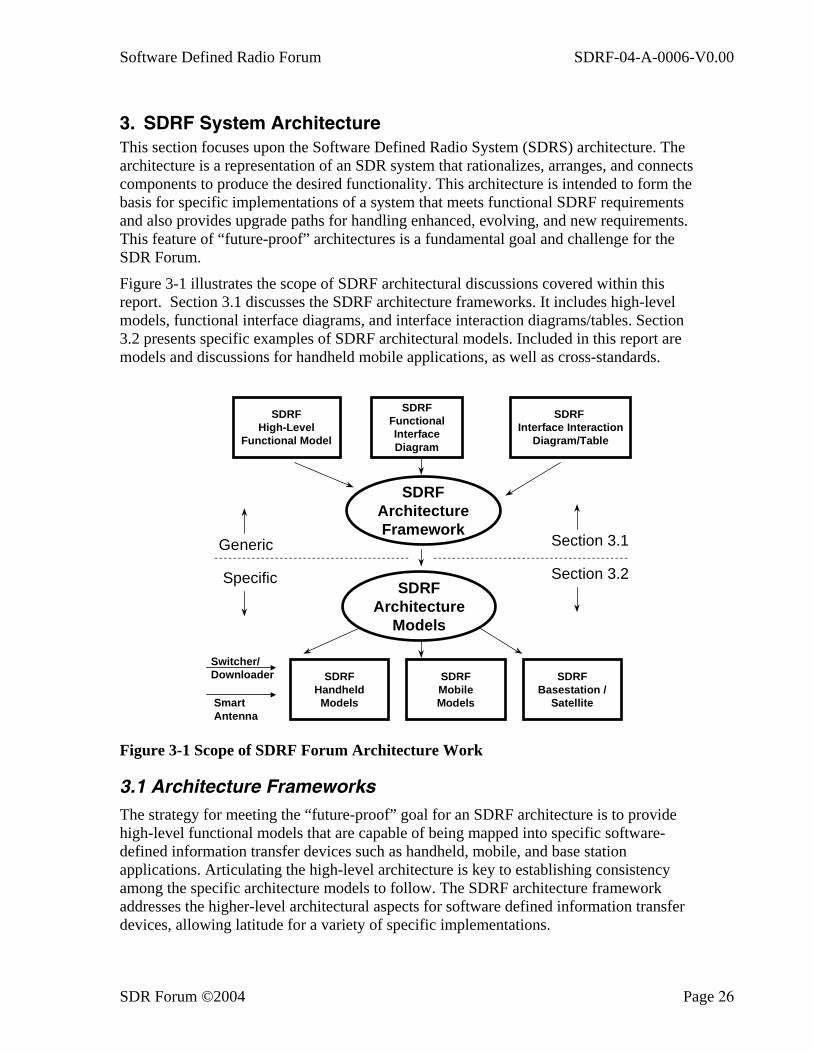
Figure 3-1 illustrates the scope of SDRF architectural discussions covered within this report. Section 3.1 discusses the SDRF architecture frameworks. It includes high-level models, functional interface diagrams, and interface interaction diagrams/tables. Section 3.2 presents specific examples of SDRF architectural models. Included in this report are models and discussions for handheld mobile applications, as well as cross-standards.
SDRFHigh-Level
Functional Model
SDRF Interface Interaction
Diagram/Table
SDRFFunctionalInterfaceDiagram
SDRFArchitectureFramework
SDRFArchitecture
Models
SDRFHandheld
Models
SDRFBasestation /
Satellite
Generic
Specific
Section 3.1
Section 3.2
SDRFMobileModels
Switcher/Downloader
SmartAntenna
Figure 3-1 Scope of SDRF Forum Architecture Work
3.1 Architecture Frameworks The strategy for meeting the “future-proof” goal for an SDRF architecture is to provide high-level functional models that are capable of being mapped into specific software-defined information transfer devices such as handheld, mobile, and base station applications. Articulating the high-level architecture is key to establishing consistency among the specific architecture models to follow. The SDRF architecture framework addresses the higher-level architectural aspects for software defined information transfer devices, allowing latitude for a variety of specific implementations.
Software Defined Radio Forum SDRF-04-A-0006-V0.00
SDR Forum ©2004 Page 27
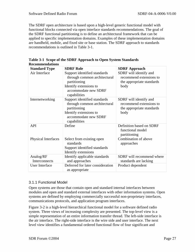
The SDRF open architecture is based upon a high-level generic functional model with functional blocks connected via open interface standards recommendations. The goal of the SDRF functional partitioning is to define an architectural framework that can be applied to specific implementation domains. Examples of these implementation domains are handheld, mobile, and fixed site or base station. The SDRF approach to standards recommendations is outlined in Table 3-1.
Table 3-1 Scope of the SDRF Approach to Open System Standards Recommendations Standard Type SDRF Role SDRF Approach Air Interface Support identified standards
through common architectural partitioning
Identify extensions to accommodate new SDRF capabilities
SDRF will identify and recommend extensions to the appropriate standards body
Internetworking Support identified standards through common architectural partitioning
Identify extensions to accommodate new SDRF capabilities
SDRF will identify and recommend extensions to the appropriate standards body
API Define Definition based on SDRF functional model partitioning
Physical Interfaces Select from existing open standards
Support identified standards Identify extensions
Combination of above approaches
Analog/RF Interconnects
Identify applicable standards and approaches
SDRF will recommend where standards are lacking
User Interface Deferred for later consideration as appropriate
Product dependent
3.1.1 Functional Model Open systems are those that contain open and standard internal interfaces between modules and open and standard external interfaces with other information systems. Open systems are defined by employing commercially successful non-proprietary interfaces, communications protocols, and application program interfaces.
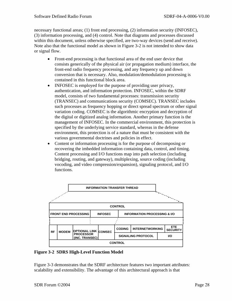
Figure 3-2 is a high-level hierarchical functional model for a software defined radio system. Three views of increasing complexity are presented. The top-level view is a simple representation of an entire information transfer thread. The left-side interface is the air interface. The right-side interface is the wire side and user interface. The next level view identifies a fundamental ordered functional flow of four significant and
Software Defined Radio Forum SDRF-04-A-0006-V0.00
SDR Forum ©2004 Page 28
necessary functional areas; (1) front end processing, (2) information security (INFOSEC), (3) information processing, and (4) control. Note that diagrams and processes discussed within this document, unless otherwise specified, are two-way devices (send and receive). Note also that the functional model as shown in Figure 3-2 is not intended to show data or signal flow.
• Front-end processing is that functional area of the end user device that consists generically of the physical air (or propagation medium) interface, the front-end radio frequency processing, and any frequency up and down conversion that is necessary. Also, modulation/demodulation processing is contained in this functional block area.
• INFOSEC is employed for the purpose of providing user privacy, authentication, and information protection. INFOSEC, within the SDRF model, consists of two fundamental processes: transmission security (TRANSEC) and communications security (COMSEC). TRANSEC includes such processes as frequency hopping or direct spread spectrum or other signal variation coding. COMSEC is the algorithmic encryption and decryption of the digital or digitized analog information. Another primary function is the management of INFOSEC. In the commercial environment, this protection is specified by the underlying service standard, whereas in the defense environment, this protection is of a nature that must be consistent with the various governmental doctrines and policies in effect.
• Content or information processing is for the purpose of decomposing or recovering the imbedded information containing data, control, and timing. Content processing and I/O functions map into path selection (including bridging, routing, and gateway), multiplexing, source coding (including vocoding, and video compression/expansion), signaling protocol, and I/O functions.
CONTROL
CONTROL
INFORMATION TRANSFER THREAD
INFORMATION PROCESSING & I/OINFOSECFRONT END PROCESSING
RF MODEM OPTIONAL LINKPROCESSOR(INC. TRANSEC)
COMSECCODING INTERNETWORKING ETE
SECURITY
SIGNALING PROTOCOL I/O
Figure 3-2 SDRS High-Level Function Model
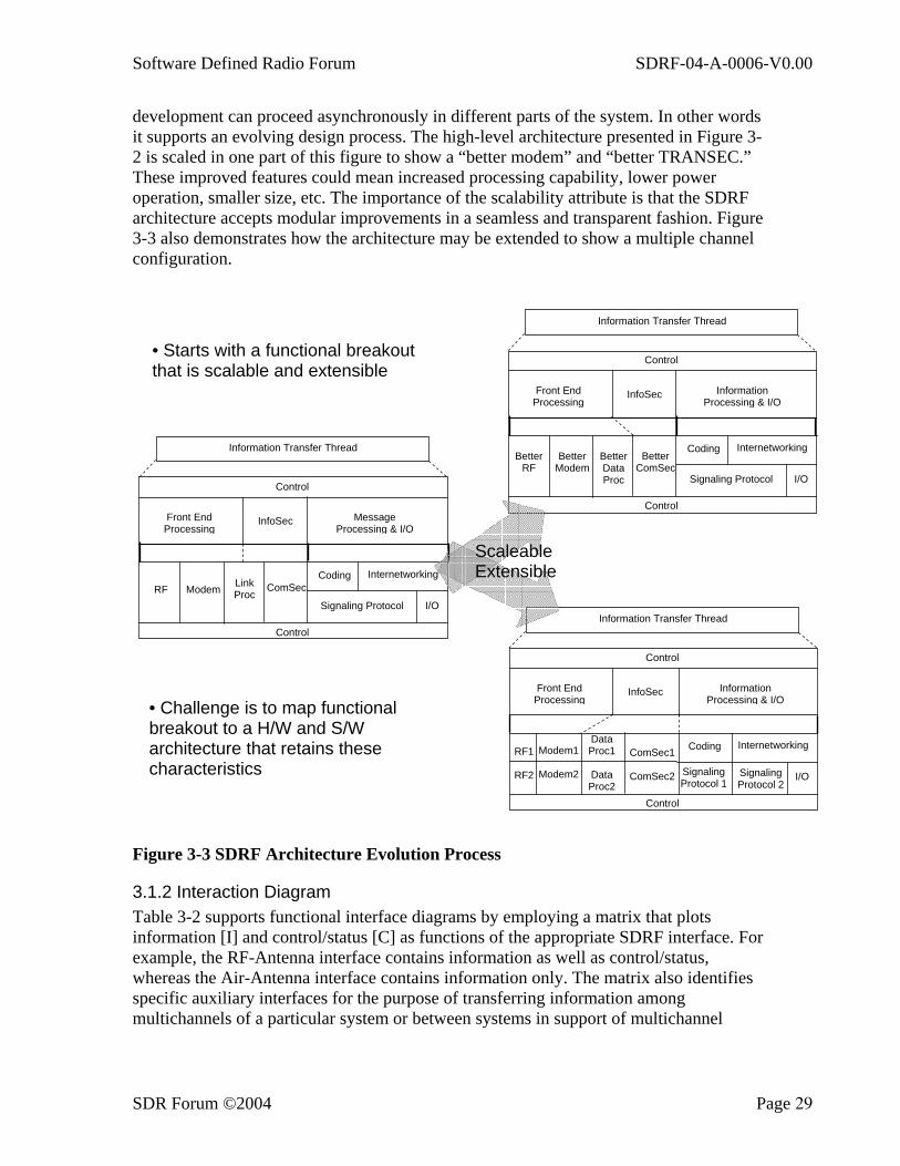
Figure 3-3 demonstrates that the SDRF architecture features two important attributes: scalability and extensibility. The advantage of this architectural approach is that
Software Defined Radio Forum SDRF-04-A-0006-V0.00
SDR Forum ©2004 Page 29
development can proceed asynchronously in different parts of the system. In other words it supports an evolving design process. The high-level architecture presented in Figure 3-2 is scaled in one part of this figure to show a “better modem” and “better TRANSEC.” These improved features could mean increased processing capability, lower power operation, smaller size, etc. The importance of the scalability attribute is that the SDRF architecture accepts modular improvements in a seamless and transparent fashion. Figure 3-3 also demonstrates how the architecture may be extended to show a multiple channel configuration.
Figure 3-3 SDRF Architecture Evolution Process
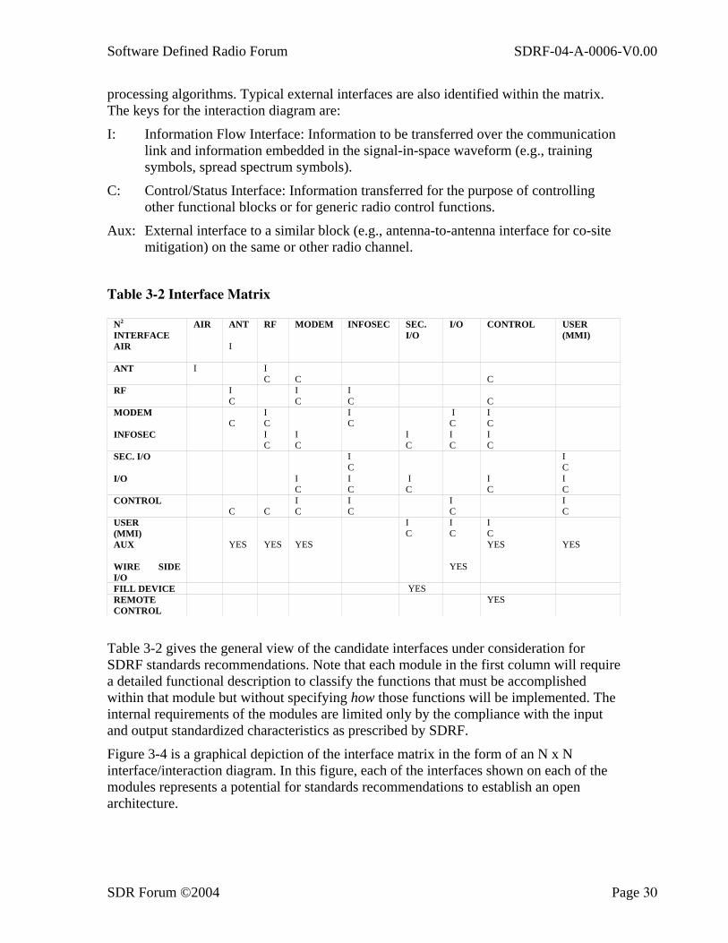
3.1.2 Interaction Diagram Table 3-2 supports functional interface diagrams by employing a matrix that plots information [I] and control/status [C] as functions of the appropriate SDRF interface. For example, the RF-Antenna interface contains information as well as control/status, whereas the Air-Antenna interface contains information only. The matrix also identifies specific auxiliary interfaces for the purpose of transferring information among multichannels of a particular system or between systems in support of multichannel
Information Transfer Thread
Control
Front End Processing
InfoSec Message Processing & I/O
RF Modem Link Proc
ComSec Coding Internetworking
Signaling Protocol I/O
Control Information Transfer Thread
Control
Front End Processing
InfoSec Information Processing & I/O
RF1
RF2
Modem1
Modem2
Data Proc1
DataProc2
ComSec1
ComSec2
Coding Internetworking
Signaling Protocol 1
I/O
Control
Signaling Protocol 2
Information Transfer Thread
Control
Front End Processing
InfoSec Information Processing & I/O
BetterRF
BetterModem
BetterDataProc
Better ComSec
Coding Internetworking
Signaling Protocol I/O
Control
• Starts with a functional breakout that is scalable and extensible
• Challenge is to map functional breakout to a H/W and S/W architecture that retains these characteristics
Scaleable Extensible
Software Defined Radio Forum SDRF-04-A-0006-V0.00
SDR Forum ©2004 Page 30
processing algorithms. Typical external interfaces are also identified within the matrix. The keys for the interaction diagram are:
I: Information Flow Interface: Information to be transferred over the communication link and information embedded in the signal-in-space waveform (e.g., training symbols, spread spectrum symbols).
C: Control/Status Interface: Information transferred for the purpose of controlling other functional blocks or for generic radio control functions.
Aux: External interface to a similar block (e.g., antenna-to-antenna interface for co-site mitigation) on the same or other radio channel.
Table 3-2 Interface Matrix
N2
INTERFACE AIR ANT RF MODEM INFOSEC SEC.
I/O I/O CONTROL USER
(MMI) AIR I
ANT I
I C
C
C
RF I C
I C
I C
C
MODEM C
I C
I C
I C
I C
INFOSEC I C
I C
I C
I C
I C
SEC. I/O
I C
I C
I/O I C
I C
I C
I C
I C
CONTROL
C
C
I C
I C
I C
I C
USER (MMI)
I C
I C
I C
AUX
YES YES YES YES YES
WIRE SIDE I/O
YES
FILL DEVICE YES REMOTE CONTROL
YES
Table 3-2 gives the general view of the candidate interfaces under consideration for SDRF standards recommendations. Note that each module in the first column will require a detailed functional description to classify the functions that must be accomplished within that module but without specifying how those functions will be implemented. The internal requirements of the modules are limited only by the compliance with the input and output standardized characteristics as prescribed by SDRF.
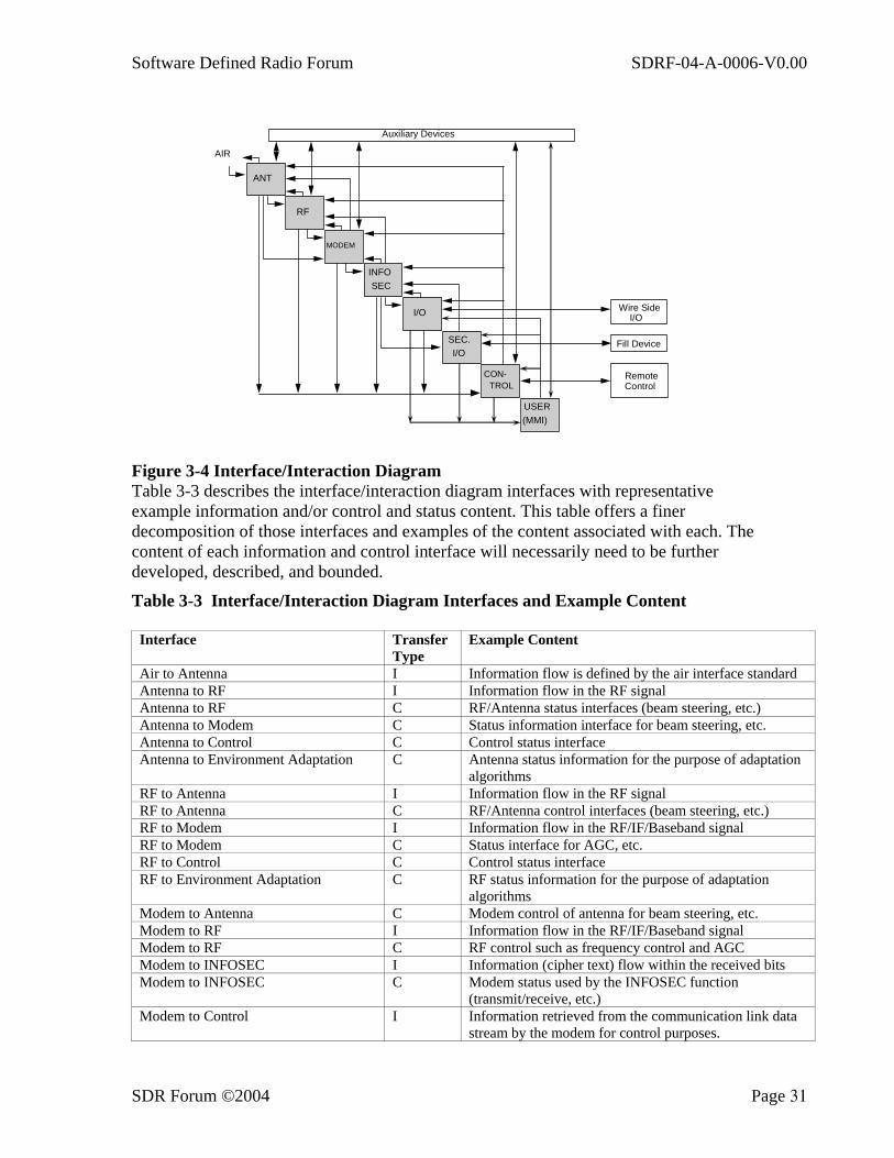
Figure 3-4 is a graphical depiction of the interface matrix in the form of an N x N interface/interaction diagram. In this figure, each of the interfaces shown on each of the modules represents a potential for standards recommendations to establish an open architecture.
Software Defined Radio Forum SDRF-04-A-0006-V0.00
SDR Forum ©2004 Page 31
ANT
USER(MMI)
RF
MODEM
INFOSEC
I/O
SEC.I/O
CON-TROL
AIR
Auxiliary Devices
Fill Device
Wire SideI/O
RemoteControl
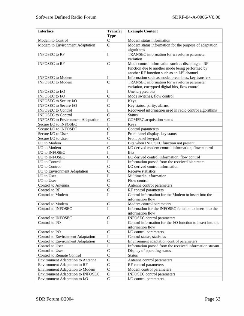
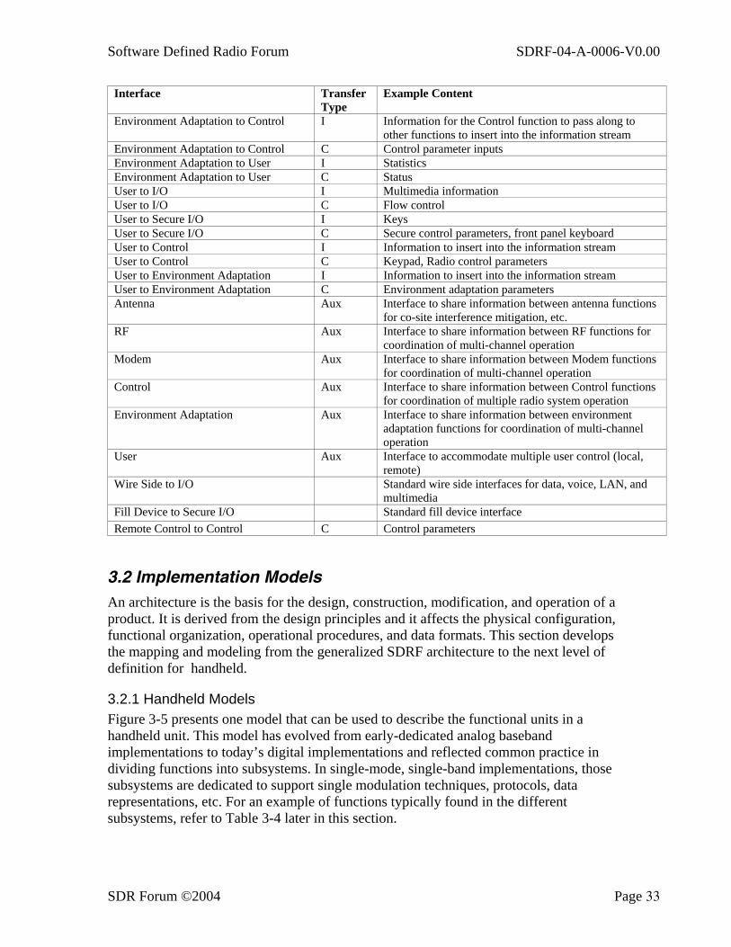
Figure 3-4 Interface/Interaction Diagram Table 3-3 describes the interface/interaction diagram interfaces with representative example information and/or control and status content. This table offers a finer decomposition of those interfaces and examples of the content associated with each. The content of each information and control interface will necessarily need to be further developed, described, and bounded.
Table 3-3 Interface/Interaction Diagram Interfaces and Example Content
Interface Transfer Type
Example Content
Air to Antenna I Information flow is defined by the air interface standard Antenna to RF I Information flow in the RF signal Antenna to RF C RF/Antenna status interfaces (beam steering, etc.) Antenna to Modem C Status information interface for beam steering, etc. Antenna to Control C Control status interface Antenna to Environment Adaptation C Antenna status information for the purpose of adaptation
algorithms RF to Antenna I Information flow in the RF signal RF to Antenna C RF/Antenna control interfaces (beam steering, etc.) RF to Modem I Information flow in the RF/IF/Baseband signal RF to Modem C Status interface for AGC, etc. RF to Control C Control status interface RF to Environment Adaptation C RF status information for the purpose of adaptation
algorithms Modem to Antenna C Modem control of antenna for beam steering, etc. Modem to RF I Information flow in the RF/IF/Baseband signal Modem to RF C RF control such as frequency control and AGC Modem to INFOSEC I Information (cipher text) flow within the received bits Modem to INFOSEC C Modem status used by the INFOSEC function
(transmit/receive, etc.) Modem to Control I Information retrieved from the communication link data
stream by the modem for control purposes.
Software Defined Radio Forum SDRF-04-A-0006-V0.00
SDR Forum ©2004 Page 32
Interface Transfer Type
Example Content
Modem to Control C Modem status information Modem to Environment Adaptation C Modem status information for the purpose of adaptation
algorithms INFOSEC to RF I TRANSEC information for waveform parameter
variation INFOSEC to RF C Mode control information such as disabling an RF
function due to another mode being performed by another RF function such as an LPI channel
INFOSEC to Modem I Information such as mode, preambles, key transfers INFOSEC to Modem C TRANSEC information for waveform parameter
variation, encrypted digital bits, flow control INFOSEC to I/O I Unencrypted bits INFOSEC to I/O C Mode switches, flow control INFOSEC to Secure I/O I Keys INFOSEC to Secure I/O C Key status, parity, alarms INFOSEC to Control I Recovered information used in radio control algorithms INFOSEC to Control C Status INFOSEC to Environment Adaptation C COMSEC acquisition status Secure I/O to INFOSEC I Keys Secure I/O to INFOSEC C Control parameters Secure I/O to User I Front panel display, key status Secure I/O to User C Front panel keypad I/O to Modem I Bits when INFOSEC function not present I/O to Modem C I/O derived modem control information, flow control I/O to INFOSEC I Bits I/O to INFOSEC C I/O derived control information, flow control I/O to Control I Information parsed from the received bit stream I/O to Control C I/O derived control information I/O to Environment Adaptation C Receive statistics I/O to User I Multimedia information I/O to User C Flow control Control to Antenna C Antenna control parameters Control to RF C RF control parameters Control to Modem I Control information for the Modem to insert into the
information flow Control to Modem C Modem control parameters Control to INFOSEC I Information for the INFOSEC function to insert into the
information flow Control to INFOSEC C INFOSEC control parameters Control to I/O I Control information for the I/O function to insert into the
information flow Control to I/O C I/O control parameters Control to Environment Adaptation I Control status, statistics Control to Environment Adaptation C Environment adaptation control parameters Control to User I Information parsed from the received information stream Control to User C Display of operating status Control to Remote Control C Status Environment Adaptation to Antenna C Antenna control parameters Environment Adaptation to RF C RF control parameters Environment Adaptation to Modem C Modem control parameters Environment Adaptation to INFOSEC C INFOSEC control parameters Environment Adaptation to I/O C I/O control parameters
Software Defined Radio Forum SDRF-04-A-0006-V0.00
SDR Forum ©2004 Page 33
Interface Transfer Type
Example Content
Environment Adaptation to Control I Information for the Control function to pass along to other functions to insert into the information stream
Environment Adaptation to Control C Control parameter inputs Environment Adaptation to User I Statistics Environment Adaptation to User C Status User to I/O I Multimedia information User to I/O C Flow control User to Secure I/O I Keys User to Secure I/O C Secure control parameters, front panel keyboard User to Control I Information to insert into the information stream User to Control C Keypad, Radio control parameters User to Environment Adaptation I Information to insert into the information stream User to Environment Adaptation C Environment adaptation parameters Antenna Aux Interface to share information between antenna functions
for co-site interference mitigation, etc. RF Aux Interface to share information between RF functions for
coordination of multi-channel operation Modem Aux Interface to share information between Modem functions
for coordination of multi-channel operation Control Aux Interface to share information between Control functions
for coordination of multiple radio system operation Environment Adaptation Aux Interface to share information between environment
adaptation functions for coordination of multi-channel operation
User Aux Interface to accommodate multiple user control (local, remote)
Wire Side to I/O Standard wire side interfaces for data, voice, LAN, and multimedia
Fill Device to Secure I/O Standard fill device interface Remote Control to Control C Control parameters
3.2 Implementation Models An architecture is the basis for the design, construction, modification, and operation of a product. It is derived from the design principles and it affects the physical configuration, functional organization, operational procedures, and data formats. This section develops the mapping and modeling from the generalized SDRF architecture to the next level of definition for handheld.
3.2.1 Handheld Models Figure 3-5 presents one model that can be used to describe the functional units in a handheld unit. This model has evolved from early-dedicated analog baseband implementations to today’s digital implementations and reflected common practice in dividing functions into subsystems. In single-mode, single-band implementations, those subsystems are dedicated to support single modulation techniques, protocols, data representations, etc. For an example of functions typically found in the different subsystems, refer to Table 3-4 later in this section.
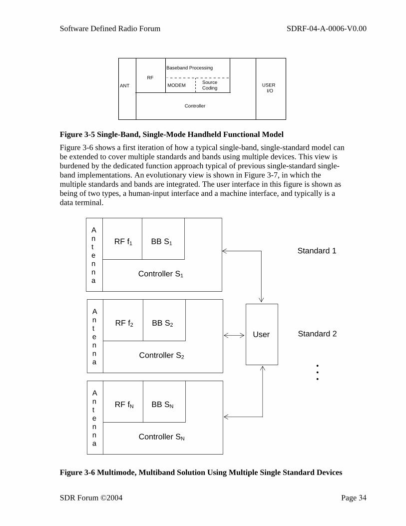
Software Defined Radio Forum SDRF-04-A-0006-V0.00
SDR Forum ©2004 Page 34
ANT
RF
Baseband Processing
MODEM SourceCoding USER
I/O
Controller
Figure 3-5 Single-Band, Single-Mode Handheld Functional Model Figure 3-6 shows a first iteration of how a typical single-band, single-standard model can be extended to cover multiple standards and bands using multiple devices. This view is burdened by the dedicated function approach typical of previous single-standard single-band implementations. An evolutionary view is shown in Figure 3-7, in which the multiple standards and bands are integrated. The user interface in this figure is shown as being of two types, a human-input interface and a machine interface, and typically is a data terminal.
Figure 3-6 Multimode, Multiband Solution Using Multiple Single Standard Devices
A n t e n n a
RF f1 BB S1
Controller S1
A n t e n n a
RF f2 BB S2
Controller S2
A n t e n n a
RF fN BB SN
Controller SN
User
Standard 1
Standard 2
• • •
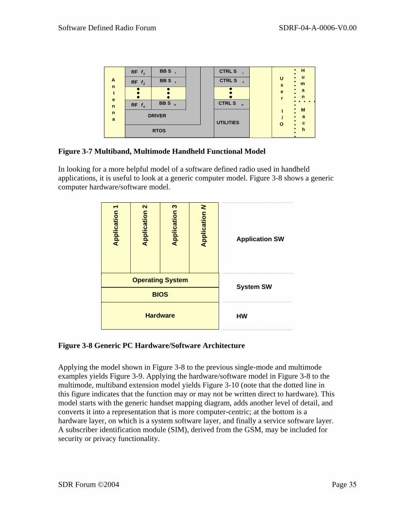
Software Defined Radio Forum SDRF-04-A-0006-V0.00
SDR Forum ©2004 Page 35
UTILITIES
CTRL S N
CTRL S 2
CTRL S 1
RTOS
DRIVER
BB S N
BB S 2
BB S 1
Antenna
User
I/
O
Human
Mach
RF f1
RF f2
RF fn
Figure 3-7 Multiband, Multimode Handheld Functional Model
In looking for a more helpful model of a software defined radio used in handheld applications, it is useful to look at a generic computer model. Figure 3-8 shows a generic computer hardware/software model.
BIOS
Hardware
App
licat
ion
1
App
licat
ion
2
App
licat
ion
3
App
licat
ion
N
Operating System
Application SW
System SW
HW
Figure 3-8 Generic PC Hardware/Software Architecture
Applying the model shown in Figure 3-8 to the previous single-mode and multimode examples yields Figure 3-9. Applying the hardware/software model in Figure 3-8 to the multimode, multiband extension model yields Figure 3-10 (note that the dotted line in this figure indicates that the function may or may not be written direct to hardware). This model starts with the generic handset mapping diagram, adds another level of detail, and converts it into a representation that is more computer-centric; at the bottom is a hardware layer, on which is a system software layer, and finally a service software layer. A subscriber identification module (SIM), derived from the GSM, may be included for security or privacy functionality.
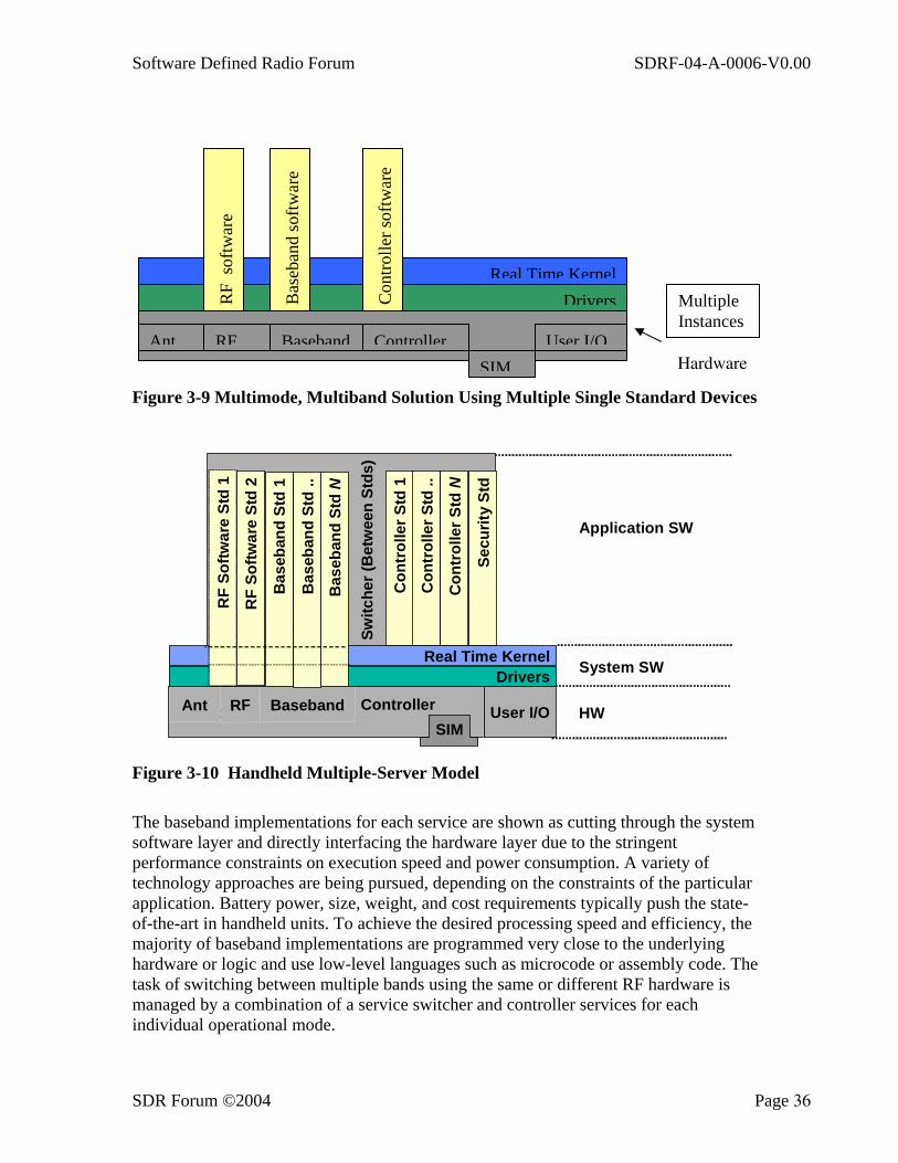
Software Defined Radio Forum SDRF-04-A-0006-V0.00
SDR Forum ©2004 Page 36
Figure 3-9 Multimode, Multiband Solution Using Multiple Single Standard Devices
ControllerAnt RF Baseband User I/O
Drivers
Controller
Con
trol
ler S
td 1
Con
trol
ler S
td ..
Con
trol
ler S
td N
Secu
rity
Std
Switc
her (
Bet
wee
n St
ds)
HW
Application SW
System SWReal Time Kernel
Bas
eban
dSt
d ..
Bas
eban
dSt
d N
Bas
eban
dSt
d 1
SIM
RF
Softw
are
Std
1
RF
Softw
are
Std
2
Figure 3-10 Handheld Multiple-Server Model
The baseband implementations for each service are shown as cutting through the system software layer and directly interfacing the hardware layer due to the stringent performance constraints on execution speed and power consumption. A variety of technology approaches are being pursued, depending on the constraints of the particular application. Battery power, size, weight, and cost requirements typically push the state-of-the-art in handheld units. To achieve the desired processing speed and efficiency, the majority of baseband implementations are programmed very close to the underlying hardware or logic and use low-level languages such as microcode or assembly code. The task of switching between multiple bands using the same or different RF hardware is managed by a combination of a service switcher and controller services for each individual operational mode.
Ant RF Baseband Controller User I/OSIM
DriversReal Time Kernel
Bas
eban
d so
ftwar
e
Con
trolle
r sof
twar
e
RF
softw
are
Multiple Instances
Hardware

Software Defined Radio Forum SDRF-04-A-0006-V0.00
SDR Forum ©2004 Page 37
Executing on the real time kernel (RTK) are two special service software modules: the service switcher and security services. The service switcher coordinates the selection and execution of the appropriate baseband service and controller service. It is both a peer and a master of the baseband service and controller service modules. As a master, it supervises the execution of the two special modules. As a peer, it depends on them for support and for providing control. The security services module monitors and manages the COMSEC and TRANSEC security resources of the system. Security services use security configuration information contained in the SIM to enable or disable various security services. COMSEC security processing would require routing the data path between the source coding and channel coding functions in the baseband module through a processing function, as pictured in Figure 3-11.
RF
CONTROL
I/O
COMSECMODEMSIGNALING PROTOCOL
CODING Internetworking
OPT. LINKPROC
Inc. TRANSEC
CONTROLCONTROLSIM
ANT
RF
MODEM
BASEBAND
USERI/O
SOURCECODING
Figure 3-11SDRF Mapping into Single-Mode, Single-Band Handheld Functional Model
If the basic wireless communications system is combined with machine intelligence to make a portable information appliance, it is sometimes called a PDA (Personal Digital Assistant) or HPC (Handheld PC). It may be desirable to combine some of the communications processing requirements with some of the information processing requirements and to execute them on the shared system resources. Figure 3-12 shows how this can be accommodated in the handheld multiple service model.

Software Defined Radio Forum SDRF-04-A-0006-V0.00
SDR Forum ©2004 Page 38
C on tro llerA nt R F B as eb an d U se r I /O
D rivers
C on tro ller
Con
trol
ler S
td 1
Switc
her (
betw
een
Stds
)
H W
A pp lic ation S W
S ys te m S W
App
let 1
N O S /O S S
N etw o rk O /SO p eratio n S up po rtS ys te m (O SS )
App
let N
R ea l T im e K ern el
Bas
eban
d St
d 1
S IMB
aseb
and
Std
..
Bas
eban
d St
d N
Con
trol
ler S
td ..
Con
trol
ler S
td N
Secu
rity
Std
Figure 3-12 Handheld Multiple Service Model with PDA Extension
The NOS/OSS (Network Operating System/Operating Support System) is a “shell” that executes on top of the RTK. It has different service requirements than the controllers. For example, it may allow more liberal interrupt policies, etc. The NOS/OSS must have a SDK (software development kit) that allows users, carriers, and manufacturers, as well as software developers, to easily develop, field, and support applications.
Applets provide functionality that can be resident on the handheld device, in the network, at a remote site or some combination of these three. Applets provide the user with such functionality as computer applications, computer-assisted communications, intelligent agents, and so on.
Multimedia handhelds and wearables can be supported by adding a resource manager for the user interface, as shown in Figure 3-13. This resource manager mediates between the basic communications functionality and two types of interfaces. The first is an array of physically attached (“local”) interfaces that support both human users and attachment to other machine intelligence. The second is an array of interfaces distributed around the user’s body and connected to the basic communications functionality by a Personal Area Network (PAN).
ControllerControllerAnt RF Baseband User I/O
Drivers
Con
trol
ler S
td 1
Con
trol
ler S
td ..
Con
trol
ler S
td N
Se
curit
y St
d
Switc
her (
Bet
wee
n St
ds)
Local MMI
Personal Area Network
Real Time Kernel
Bas
eban
d St
d ..
Bas
eban
d St
d N
Bas
eban
d St
d 1
SIM
User I/OResource
Mgr.
Other
MMISensorsNOS/
OSS
App
let 1
App
let N
PAN I/O
Local I/O
Local Machine I/O Figure 3-13 Wearable Multiple Service Model with PDA Extensions
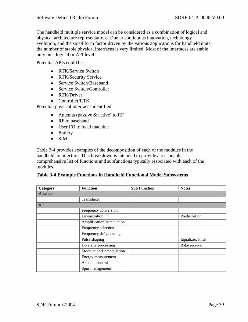
Software Defined Radio Forum SDRF-04-A-0006-V0.00
SDR Forum ©2004 Page 39
The handheld multiple service model can be considered as a combination of logical and physical architecture representations. Due to continuous innovation, technology evolution, and the small form factor driven by the various applications for handheld units, the number of stable physical interfaces is very limited. Most of the interfaces are stable only on a logical or API level.
Potential APIs could be
• RTK/Service Switch • RTK/Security Service • Service Switch/Baseband • Service Switch/Controller • RTK/Driver • Controller/RTK
Potential physical interfaces identified:
• Antenna (passive & active) to RF • RF to baseband • User I/O to local machine • Battery • SIM
Table 3-4 provides examples of the decomposition of each of the modules in the handheld architecture. This breakdown is intended to provide a reasonable, comprehensive list of functions and subfunctions typically associated with each of the modules.
Table 3-4 Example Functions in Handheld Functional Model Subsystems
Category Function Sub Function Notes Antenna Transducer RF Frequency conversion Linearization Predistortion Amplification/Attenuation Frequency selection Frequency de/spreading Pulse shaping Equalizer, Filter Diversity processing Rake receiver Modulation/Demodulation Energy measurement Antenna control Spur management
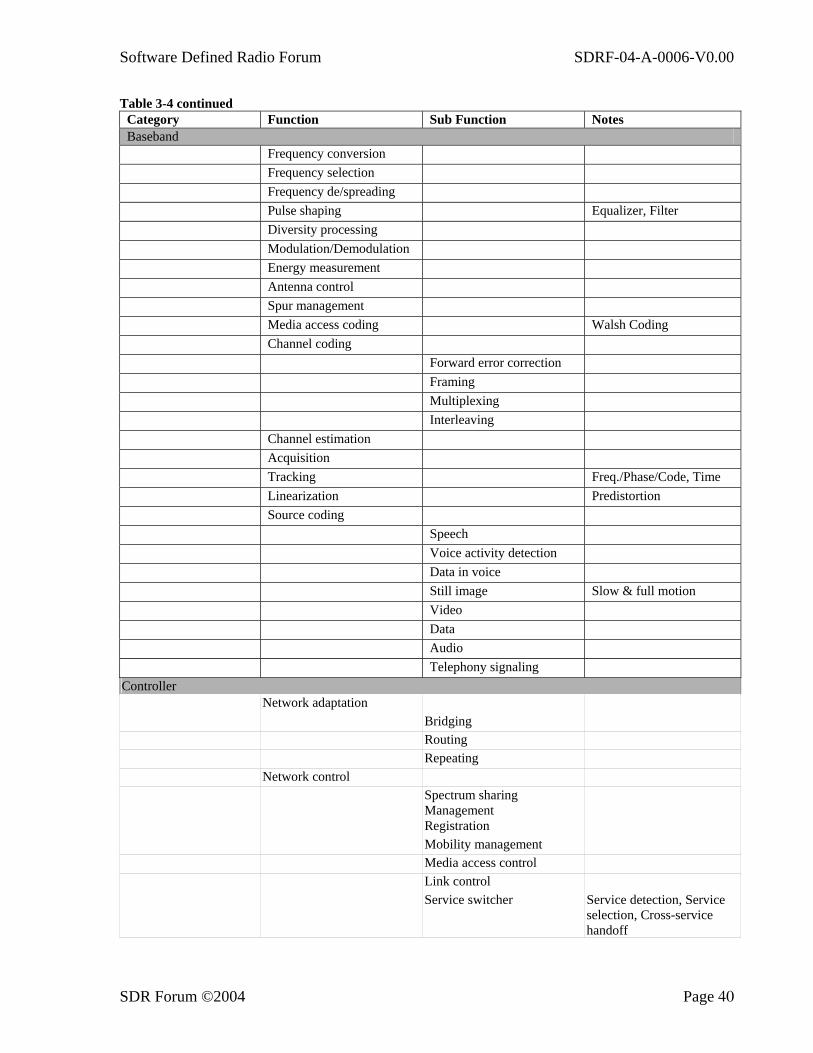
Software Defined Radio Forum SDRF-04-A-0006-V0.00
SDR Forum ©2004 Page 40
Table 3-4 continued Category Function Sub Function Notes Baseband Frequency conversion Frequency selection Frequency de/spreading Pulse shaping Equalizer, Filter Diversity processing Modulation/Demodulation Energy measurement Antenna control Spur management Media access coding Walsh Coding Channel coding Forward error correction Framing Multiplexing Interleaving Channel estimation Acquisition Tracking Freq./Phase/Code, Time Linearization Predistortion Source coding Speech Voice activity detection Data in voice Still image Slow & full motion Video Data Audio Telephony signaling
Controller Network adaptation Bridging Routing Repeating Network control Spectrum sharing
Management
Registration Mobility management Media access control Link control Service switcher Service detection, Service
selection, Cross-service handoff

Software Defined Radio Forum SDRF-04-A-0006-V0.00
SDR Forum ©2004 Page 41
Table 3-4 concluded Category Function Sub Function Notes Controller (continued) Information security User authentication Traffic encryption Payload Network encryption Preamble, … Transmission security Transec Key management Node authentication User I/O MMI Speech recognition Handwriting recognition Image recognition Biometric recognition
(Speech, eyeball, handwriting, keyboard, pointer)
Image scanning Speech synthesis Display management Audio management
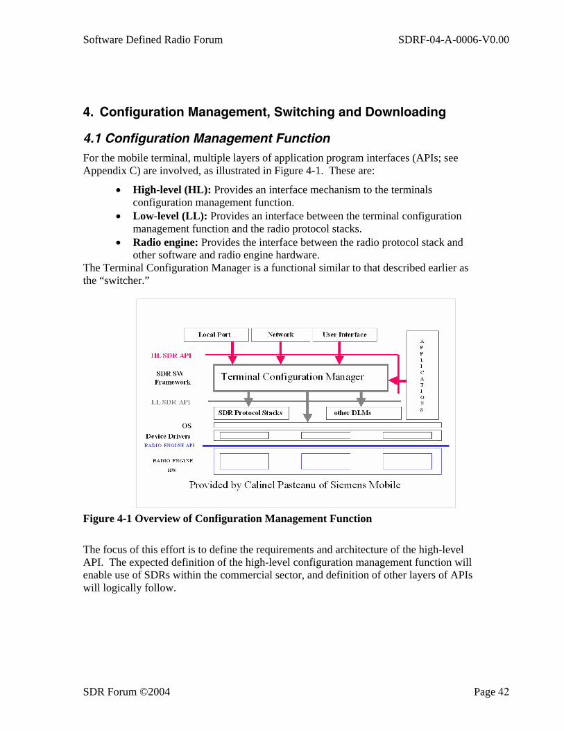
Software Defined Radio Forum SDRF-04-A-0006-V0.00
SDR Forum ©2004 Page 42
4. Configuration Management, Switching and Downloading
4.1 Configuration Management Function For the mobile terminal, multiple layers of application program interfaces (APIs; see Appendix C) are involved, as illustrated in Figure 4-1. These are:
• High-level (HL): Provides an interface mechanism to the terminals configuration management function.
• Low-level (LL): Provides an interface between the terminal configuration management function and the radio protocol stacks.
• Radio engine: Provides the interface between the radio protocol stack and other software and radio engine hardware.
The Terminal Configuration Manager is a functional similar to that described earlier as the “switcher.”
Figure 4-1 Overview of Configuration Management Function
The focus of this effort is to define the requirements and architecture of the high-level API. The expected definition of the high-level configuration management function will enable use of SDRs within the commercial sector, and definition of other layers of APIs will logically follow.
Software Defined Radio Forum SDRF-04-A-0006-V0.00
SDR Forum ©2004 Page 43
4.1.1 Wireless Terminal Configuration Four basic goals in this process are to:
• Leverage previous work done with the SDR Forum and other openly published efforts regarding wireless terminal configuration
• Involve parties from various aspects of the wireless communications sector (i.e., manufacturers, research and development groups, network operators, and service providers)
• Provide a flexible architecture and anticipate the full range of requirements for future terminal configuration
• Coordinate with other complementary efforts within the SDR Forum (for example: general API development efforts and efforts related to remote download of radio software)
4.2 Analysis Approach Three key steps define the analysis work. The result is the development of a baseline definition that is suitable to support wireless terminal remote configuration.
• Use-case analysis: Focuses on definition of scenarios that drive the overall architecture configurable wireless terminals
• Requirements definition effort: Focuses on distilling, from the use-case analysis, key requirements of a configuration management function within a wireless terminal
• Architecture definition task: Focuses on the definition of salient architecture features that result from the requirement analysis
The resulting architecture is technology independent because it can be implemented in any language and/or hardware architecture.
4.2.1 Use-Case Analysis The use-case analysis involves the review of a number of documents. Initially all aspects of configuration and download are reviewed. Functions need to be separated into two categories: (1) those focused on download, and (2) those involved in the actual configuration of a terminal.
The reconfiguration functionality that results from the use-case analysis for radio configuration is illustrated in Figure 4-2.

Software Defined Radio Forum SDRF-04-A-0006-V0.00
SDR Forum ©2004 Page 44
Figure 4-2 Main Use-Case Analysis
4.2.1.1. Configure Terminal Scenario
Four major capabilities are included in the configure terminal scenario:
• Identification of available modes of operation. • Ability to conduct capability set and capability get actions with the SDR
terminal. This effectively includes requesting the terminal of capabilities and setting new ones.
• Monitoring Quality of Service (QoS): Assists the terminal in determining whether a mode reconfiguration is to be required or appropriate.
• Switching mode of the terminal. This involves the reconfiguration of the terminal from one air interface operational mode to another.
4.2.1.2. Downloading and Configuration
Changing the operating mode of an SDR terminal involves downloading the appropriate software and parameters.
The configuration steps for installing the software and parameters and initiating the new radio functionality entail five (main) steps. The first two, which are download related, are:
• Transport of air interface modules and parameters to a terminal • Storage of modules and parameters on the terminal
These two steps are addressed by standards and profiles that are currently being developed in general support of the download of application and radio functionality software.
The last three steps are:
C o nf ig ure T erm ina l
Id ent ify A v a ila b le M o d es
C a p a b ility S et & G et
S w itc h M o d e
U serA pplica t ion
N etw orkO pera tor
M ode D etect ion
R a d io C o n f ig u r a t io n M a in U s e -C a s e D ia g r a m
M anufactu rer
P ong
M o nito r Q o S
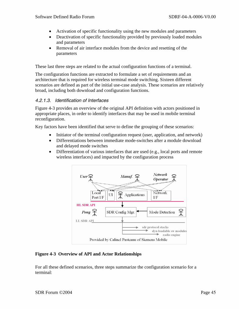
Software Defined Radio Forum SDRF-04-A-0006-V0.00
SDR Forum ©2004 Page 45
• Activation of specific functionality using the new modules and parameters • Deactivation of specific functionality provided by previously loaded modules
and parameters • Removal of air interface modules from the device and resetting of the
parameters
These last three steps are related to the actual configuration functions of a terminal.
The configuration functions are extracted to formulate a set of requirements and an architecture that is required for wireless terminal mode switching. Sixteen different scenarios are defined as part of the initial use-case analysis. These scenarios are relatively broad, including both download and configuration functions.
4.2.1.3. Identification of Interfaces
Figure 4-3 provides an overview of the original API definition with actors positioned in appropriate places, in order to identify interfaces that may be used in mobile terminal reconfiguration.
Key factors have been identified that serve to define the grouping of these scenarios:
• Initiator of the terminal configuration request (user, application, and network) • Differentiations between immediate mode-switches after a module download
and delayed mode switches • Differentiation of various interfaces that are used (e.g., local ports and remote
wireless interfaces) and impacted by the configuration process
Figure 4-3 Overview of API and Actor Relationships
For all these defined scenarios, three steps summarize the configuration scenario for a terminal:
Software Defined Radio Forum SDRF-04-A-0006-V0.00
SDR Forum ©2004 Page 46
• Actors initiate (request) a configuration change. • The terminal completes configuration. • Test of new mode of operation is conducted and reported.
4.2.1.4. Actors
Several actors (entities that can initiate a configuration change) are defined:
• User • Network operator • Application • The mode detection function, which resides internal to the mobile terminal
above the lower-level API, can initiate configuration change requests locally. • The pong actor, which resides within the terminal, provides an ability to
initiate configuration when the terminal itself detects an error. This error requires a full configuration to recover.
Initiation of a mode change does not convey that an actor can direct a mode change in an autonomous manner. Any request or initiation of a mode change has to involve interaction with other appropriate entities (e.g., networks) before a mode switch occurs.
Three actors (user, manufacturer, and network operator) are external to the mobile terminal. These actors interact with the terminal configuration management function through four (basic) interfaces:
• Local port (e.g., serial, Bluetooth) that does not require configuration of an air interface standard to use
• User interface • Network interface that requires configuration of an air interface to use • Application that does not reside on the terminal as a radio module (it acts for
the other external entities to enable configuration change requests)
4.2.2 Requirements Definition The three basic requirements that result from the analysis include:
• The configuration manager must be able to access various components of an SDR in a modular manner.
• The configuration manager function must have access to an interface that provides for a mechanism for querying a mobile terminal for the identity and status of installed modules or the entire radio personality.
• The configuration manager function is able to trigger the activation and deactivation of an installed module or set of modules.
These requirements lead to definition of particular requirements for the configuration management function and its interfaces. The software, the binary images, and the parameter required for operation of a mobile terminal, in that order, must be segmented into meaningful groups that allow access of different functions within the terminal.

Software Defined Radio Forum SDRF-04-A-0006-V0.00
SDR Forum ©2004 Page 47
Eight possible components are:
• Management and control unit (MCU): Provides the capability to manage and control the flow of digital data to configure the terminal (e.g., bootstrapping, software downloading, and lifecycle management)
• Antenna (A): May need to be reconfigured to be utilized for different standards and specific users
• Radio transmit/receive unit (RF): Responsible for analog transceiver functionality in the mobile terminal
• Digital signal processor array (DSPA): Responsible for digital transceiver and modem functionality in the mobile terminal
• Digital protocol unit (DPU): Responsible for the higher layers of the protocol stack within the mobile terminal
• Information and security unit (ISU): Responsible for all information and security-related aspects of the mobile terminal
• Input output unit (IOU): Provides interfaces to various media drivers (speaker, display, and microphone) and other local ports (serial port)
• Optional components (OC): A generic optional components (OC) module is provided to allow for generic evolution of this architecture without requirement for revision of these components. OCs can be added with any functionality associated with them. Separation of the radio terminal into different components allows for partitioning of radio functionality into separate units.
All units are triggered and managed by the configuration manager; therefore applications do not have to be concerned about each unit. This enables portability and a minimum of interfaces to be known by applications.
4.2.3 Capabilities Capabilities must be put in place on the terminal to enable the querying of component modules, the installation and removal of components, and the activation of component modules. The three commands to do this are to be used at the system (mobile terminal) or component level:
1. Identify: The process of querying an SDR for the identification and status of an installed module
2. Configure: The process of installing and removing a module 3. Initiate: The process of activating an install module
Any of these commands can be used to configure the terminal or convey information on the configuration between the terminal and an external actor. Additionally, the configuration management function of the radio can utilize any of these three commands to configure, initiate, or query a specific component of the radio.
The configuration and initiate commands have only two outcomes: success or failure. Upon installation of a module into a specific component of the radio or the initiation previously installed, one of the two reports will be made to identify success or failure pertaining to the particular step being done.
Software Defined Radio Forum SDRF-04-A-0006-V0.00
SDR Forum ©2004 Page 48
The Identification command requires a response via the configuration manager about the SDR capabilities of the terminal. There is no requirement in this configuration management function that any particular type of language, hardware, or operating system be used in the configuration or operation of a radio. It is expected that prior to download a manufacturer will have validated accepted configurations of the software and parameter with a particular handset. The focus is to allow for controlled remote configuration of a terminal, not necessarily requiring portability of all software and parameters downloaded to a terminal. Every module will have a particular personality (e.g., type of air interface supported) and will also be identified as valid for a particular handset or set of handsets. This is not a drawback for this approach because this type of validation of modules with specific hardware is expected to be required for use of SDRs to avoid interface to a network from manufacturing terminals.
4.3 Switcher Downloader Modular, multimode terminals can be fielded in a totally terminal-centric fashion in which the network has no knowledge of the fact that the terminal can change from one configuration to another. For example, the terminal can initiate a session with network type A. When it comes to the border of that network technology, the handset can take down the session with network A and initiate a session with network B. It is also possible to have some intelligence outside the terminal to help coordinate this process. But to achieve the full functional advantages inherent in SDRF mechanisms, facilities are needed for cooperation and hand-off between terminals and networks using different modes and different bands. These mechanisms should support terminal-directed hand-offs, network-directed hand-offs, and combinations of the two.
Other standards bodies are responsible for maintaining the standards that govern each specific service (single mode/band). It is SDRF’s intention to work with these other bodies to develop an umbrella model and recommendations for message types and protocol extensions. Then these other bodies can use, each in their own domain, the model and recommendations to develop terminals and networks that cooperate across modes and bands. This section presents some examples of the requirements from several perspectives and an approach to meeting them.
Commercial cellular/PCS users need hand-offs between service types and service providers. This requirement is derived from a combination of economic factors, such as limited spectral resources, legacy systems, geopolitical forces, and so on. Examples include, among others, CDMA/TDMA/AMPS hand-offs as well as cordless, wireless LANs, CSMA.
Civilian/aviation users need simultaneous operation across several modes/bands. For example, interoperability requirements among different branches/standards include the provision of different aviation services for an analog voice, minimum shift keying (MSK), TDMA, CSMA, and so on. Today, hand-offs are often done by voice command.
Emergency service coordination requires the support of many standards with significant interworking/translation requirements.
An example of one approach to addressing these various requirements to support hand-offs between CDMA cellular/PCS and TDMA cellular/PCS in a U.S. standards

Software Defined Radio Forum SDRF-04-A-0006-V0.00
SDR Forum ©2004 Page 49
environment is to use the advanced mobile phone system (AMPS) as a bridge. In U.S. cellular standards environments, CDMA and TDMA handsets are required to also support the AMPS mode. Figure 4-4 shows how AMPS can be used to carry signaling information between the mobile unit and the infrastructure.
Another approach is to provide extensions to the message formats in both environments that allow the mobile unit and the infrastructure to negotiate the desired service type to use for the session or session continuation. Figures 4-4 and 4-5 illustrate this approach.
CDMASystem
TDMASystem
Signaling Strategy: CDMA DS/MSC notify TDMA MSC of hand-off CDMA and TDMA MSCs notify HLR CDMA BS notifies MS of change in mode after hand-offAlternately: MS switches to AMPS after crossing, then negotiate for TDMA
MSC: Mobile Switching Center HLR: Home Location Register BS: Base Station AMPS: Advanced Mobile Phone System
Figure 4-4 Signaling Strategy
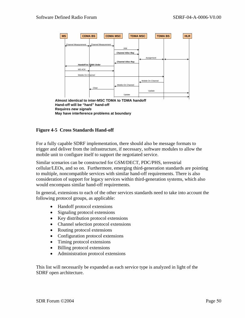
Software Defined Radio Forum SDRF-04-A-0006-V0.00
SDR Forum ©2004 Page 50
MS CDMA BS TDMA MSC TDMA BS HLRCDMA MSC
Channel Measurement Channel Measurement
IAM
Channel Alloc Req
Assignment
Channel Alloc Rsp.Handoff-to-TDMA Order
MS ACK
Mobile On Channel
Mobile On Channel
Mobile On ChannelClear
Update
Update
Almost identical to inter-MSC TDMA to TDMA handoffHand-off will be “hard” hand-offRequires new signalsMay have interference problems at boundary
Figure 4-5 Cross Standards Hand-off
For a fully capable SDRF implementation, there should also be message formats to trigger and deliver from the infrastructure, if necessary, software modules to allow the mobile unit to configure itself to support the negotiated service.
Similar scenarios can be constructed for GSM/DECT, PDC/PHS, terrestrial cellular/LEOs, and so on. Furthermore, emerging third-generation standards are pointing to multiple, noncompatible services with similar hand-off requirements. There is also consideration of support for legacy services within third-generation systems, which also would encompass similar hand-off requirements.
In general, extensions to each of the other services standards need to take into account the following protocol groups, as applicable:
• Handoff protocol extensions • Signaling protocol extensions • Key distribution protocol extensions • Channel selection protocol extensions • Routing protocol extensions • Configuration protocol extensions • Timing protocol extensions • Billing protocol extensions • Administration protocol extensions
This list will necessarily be expanded as each service type is analyzed in light of the SDRF open architecture.
Software Defined Radio Forum SDRF-04-A-0006-V0.00
SDR Forum ©2004 Page 51
4.4 Software Download A major requirement of a software-defined/adaptable handset or terminal will be the ability to reprogram the device via download of new software and/or parameter data to the terminal. This will permit, for example:
• Download of a new user application • Download of a new graphical user interface (GUI) to change or improve the
“look and feel” • Download of a protocol stack, physical-layer configuration software, and
control software to implement a different air-interface standard • Incremental download of new software and/or parameters to improve
performance (for example, a modified source codec) • Download of software bug-fixes (both applications and physical-layer/control
software)
The ability to reconfigure by download is a key differentiator of software defined handsets from traditional single-standard implementations, and offers significant advantages of flexibility to manufacturers, service providers, and users.
Methods by which software may be downloaded include:
• By installing new software from a new SIM card • From another computer, via for example a PC-card (PCMCIA) link • From a networked terminal • Over-the-air
Each download method raises issues to be addressed in compiling standardization recommendations. For example:
• Security of downloaded code • Integrity of downloaded code • Standard API for establishing a download link to the handheld terminal • Billing
More general standards issues relating to “application and configuration” software download might be:
• Choice of terminal-independent language for “programming” the terminal (e.g., a language such as Java 2TM may be used for higher-level applications that are sufficiently abstracted from specific hardware features, but would be less suited to re-configuring the radio link, which may employ specific proprietary hardware features)
• Ownership and licensing of downloaded software • Type approval of both terminals and associated software applications making
use of operators’ resources
Software Defined Radio Forum SDRF-04-A-0006-V0.00
SDR Forum ©2004 Page 52
• Matching new features and applications to the “capabilities” of the terminal at which they are targeted. This could lead to classification of handheld terminals and applications, such that an application may be downloaded and executed only if the underlying terminal capabilities can guarantee that the application can be supported (e.g., processing power, memory, and deterministic task execution).
Software-defined reconfigurable terminals can potentially reduce the requirements for de jure standardization within the terminal, allowing functionality to develop in unison with terminal technology developments. This can be the case only if the means of programming the terminal and of ensuring its compliance subsequent to programming can be precisely defined and managed; this will be a major work area for SDRF in producing standardization recommendations.
4.5 Documents from Industry Associations The Open Mobile Alliance (OMA) and the SDR Forum have prepared documentation that addresses download specifications.
4.5.1 Open Mobile Alliance Among other activities, the Open Mobile Alliance is in the process of updating the download over-the-air (OTA) specification (Doc 1 below). This specification is for applications software download. This new version (V2.0) is expected to be completed in 2004.
In addition, the OMA is in the process of developing a firmware OTA download specification for “non-applications” software (OTA Firmware Update Protocol; working document, not publicly available). The OMA term “non-applications” is the same as the term “operational software” used by the SDR Forum. The non-applications OTA download specification will satisfy the requirements generated from the non-applications software download use case in the OMA Device Management Requirements document (Doc. 2 below). Both of the OMA download documents reference an OMA security specification (Doc. 3 below).
1. Generic Content Download Over the Air Specification, Version 1.0, OMA Document OMA-Download-OTA-v1_0-20021219-C (published, publicly available document)
2. OMA (2003), Device Management Requirements, Version 1.0, July 24 2003; OMA-REQ-DevMngmt-V1_0-20030724-C OMA-SyncML-DMSecurity-V1_1_2-20031209-D
3. SyncML Device Management Security, Version 1.1.2, OMA Document OMA-SyncML-DMSecurity-V1_1_2-20031209-D (OMA-SyncML-DMSecurity-V1_1_2-20031209-D)
4.5.2 SDR Forum DL-DFN (Doc. 1 below) provides a download overview and definitions. DL-REQ (Doc. 2 below) provides high-level functional requirements for all aspects of download, including security. DL-SIN (Doc. 3 below) will provide detailed requirements for
Software Defined Radio Forum SDRF-04-A-0006-V0.00
SDR Forum ©2004 Page 53
download security and a summary of some security specifications that are applicable to secure software download. Document DL-SIN will be completed in 2004.
1. “DL-DFN, Overview and Definition of Software Download for RF
Reconfiguration,” SDR Forum Document SDRF-02-A-0002, August 2002 (published, publicly available document on SDRF Website).
2. “DL-REQ, “Requirements for Radio Software Download for RF Reconfiguration,” SDR Forum Document SDRF-02-A-0007, November 2002 (published, publicly available document on SDRF Website).
3. “DL-SIN, Security Aspects of Operational Software Download for Commercial Wireless Devices” (Work in progress, SDRF-02-W-0005-V0.22 is available to SDR Forum members only in the Working Documents section of the SDR Forum Website).
4. “SDR System Security,” SDR Forum Document SDRF-02-A-0006 (published, publicly available document on SDRF Website).
5. SDR FORUM SDRF-03-I-0052-V0.00, C.F. Lam; H.J. Wang; K. Sakaguchi; J. Takada; and K. Araki. Secure Global Roaming Architecture for Software Defined Radio (published, publicly available document on the SDRF).
Software Defined Radio Forum SDRF-04-A-0006-V0.00
SDR Forum ©2004 Page 54
5. RF/BB Interface The RF/BB Interface is located between the RF transceiver(s) and the digital baseband (BB) very large scale integrated (VLSI) circuit in a commercial handset SDR architecture. The term RF transceiver is meant to comprise up- and down-conversion and other mainly analog signal processing stages. Digital baseband refers to a programmable/ reconfigurable digital signal processing unit. A more precise delineation between an RF transceiver and digital baseband, including the location of mixed signal circuitry, depends on the RF/BB interface definition itself. Therein, two aspects may be considered:
1. The RF/BB interface as a conceptual interface with some degree of visibility in the virtual radio architecture and therefore implications to the software communications architecture
2. The RF/BB interface as a physical interface between separate hardware components (RF transceiver and digital baseband VLSI, respectively) eventually designed and manufactured by different parties in accordance with a common RF/BB interface standard
Only the latter aspect is discussed in this section. The degree to which the RF/BB interface is visible as a physical interface and hence the degree to which it is of interest for standardization depends on the directions taken in semiconductor technology, chip partitioning, and packaging.
The general technology trend is in favor of single-chip CMOS integration of both RF and baseband functionality in a single System on Chip (SoC). In this case, the RF/BB interface is hidden and the SoC design can do well without standardization. Single-chip integration, however, although appropriate for well-established hardware architectures and high volume, is not so during the introduction of an innovative and evolving technology such as commercial handset SDR. The following observations support this view:
• Innovation of BB signal processing architectures for SDR continues, and is independent of multiband, multistandard RF transceiver architectures.
• There is no “one size fits all” commercial handset SDR design. Different market segments correspond to different capability requirements with respect to BB signal processing performance but also with respect to supported RF bands, modulations, and so on. The option to choose and combine different RF and BB integrated circuits (ICs) from different vendors is relevant.
• Due to the lack of a “universal” RF transceiver chip for HF to UNII bands, handset designers need the option to combine a programmable digital BB VLSI with a selection of RF transceivers.
• Handsets may support more than a single communication link or broadcast service at a time. Multiple RF receivers and/or transmitters (in varying numbers for different handsets) may therefore be required.
These observations indicate that the introduction of SDR in the commercial handset arena is to go through a phase of multi-chip radio architectures that will benefit from an open interface, which effectively supports modular design. The interoperability between digital BB ICs and (multiple) RF transceiver ICs from different vendors is the primary objective. It will alleviate migration to SDR for handset manufacturers and facilitate

Software Defined Radio Forum SDRF-04-A-0006-V0.00
SDR Forum ©2004 Page 55
market access for suppliers who are specialized in innovative solutions for either digital baseband or RF transceivers.
The question for location and type of a standardized RF/BB interface(s) (analog or digital) is the question for the direction taken in commercial SDR handsets with respect to chip partitioning. None of the three following options can be excluded:
(A) co-integration of analog and mixed signal modules
(B) co-integration of digital and mixed signal modules
(C) separate integration of analog, mixed signal, and digital modules
Both technology trend and the objective to arrive at an open interface that supports modular SDR design are strongly in favor of option (A). The value proposition of a software defined baseband signal processing unit lies mostly in the facts that (1) it can be combined with various RF transceivers, (2) it allows for switching between alternative RF transceivers, and further, (3) it permits parallel/time-multiplexed cooperation with more than a single RF transceiver at a time. To this end, it is desirable that the digital baseband VLSI contains a high-performance, general-purpose signal processing unit but does not otherwise restrict the hardware architecture. Option (B) is in conflict with these goals and the SDR concept at large. Option (C) can be an intermediate solution, if at all, only from a cost point of view.
Future directions taken in packaging influence the definition of the RF/BB interface in two ways. The potential role of multi-chip modules that comprise both RF transceiver and digital baseband may be discussed in analogy to that of single-chip integration, as above. The second aspect coincides with the electrical interconnect aspect of the RF/BB interface. Susceptibility to interference and related power consumption, which result in limits for high-speed on-board digital interfaces, may be mitigated by denser packaging. The approach taken with respect to standardization of an RF/BB interface for commercial handset SDR should account for possible evolution in this area. It should in particular be open for a transition from analog to digital interfacing as well as for communication standards, even though this approach has appeared to be unfavorable in the past.
5.1 Scope of RF/BB Interface Standardization The following items are candidates for standardization in the context of the RF/BB interface for a commercial handset SDR:
1. The genuine data interface for down-link and up-link transmission 2. The control interface for operational control and reconfiguration 3. The classification of signal quality characteristics at the data interface, based on a
definition of test cases Only the data interface is considered in this contribution.
5.2 Data Interface Some obvious options for the placement of the RF/BB data interface within the signal processing chain are:
(a) Continuous-time, continuous-value analog I/Q signals

Software Defined Radio Forum SDRF-04-A-0006-V0.00
SDR Forum ©2004 Page 56
(b) Discrete-time, continuous-value analog I/Q samples
(c) Discrete-time, multi-level digital I/Q samples
(d) Discrete-time, binary-string digital I/Q samples
(e) Discrete-time, digitally represented symbol values
Approaches (a), (b), and (c) are not well suited for bus type architectures but for point-to-point connections only. As already argued above, these configurations are in conflict with the objective of modularity. It requires the digital baseband IC to be equipped with a specialized interface and, for use with multiple RF transceivers, with the correct number thereof. From this point of view, analog or multi-level interfaces are discouraged.
Approaches (d) and (e) may share the same physical interface definition. An exclusive symbol interface, however, is in conflict with standard independency of the SDR architecture. In view of the objective of modularity, the digital interface is preferable due to its allowance of
• Bus type interconnect architecture (more than a single RF transceiver in alternative or parallel operation)
• Time multiplex patterns for data transmission between digital BB and several RF receivers and/or transmitters, respectively
• Time multiplex with respect to up- and downlink transmission • On-demand allocation of bus lines to RF transceivers (in a multiple RF
receiver/transmitter architecture) in accordance with the instantaneous usage scenario
• Embedding of chip address, data format, and further protocol or configuration information into the data stream
A digital interface is also preferable for supplier specialization with respect to analogue/mixed signal and general-purpose digital signal processing technology.
The current technology trend is clearly in favor of a digital interface. Option (c) is currently subject to standardization for GSM/GPRS by the DigRF industry consortium under participation of all major semiconductor suppliers. The extension of the approach to communication standards with higher RF/BB interface data rate requirements appears likely. Some communication standards (e.g., UMTS) or high-data rate WLAN, depending on the oversampling rate presented at the digital I/Q interface, lead to bit rate requirements in the range from several hundred megabits per second up to gigabits per second. Pre-filtering (for RX) or post-filtering (for TX) may be employed in these cases to reduce the interface sample rate to near the Nyquist rate.
All of the above considerations were guided by the objective of an open RF/BB interface that supports modular design; that is, compatibility of RF transceiver chips and digital BB VLSI as well as hardware architectures with different numbers of RF transceivers. Although they all result in a strong preference for a bus-type digital RF/BB interface, they do not exclude the presence of an analog RF/BB interface. Hardware architectures that refer to both are conceivable.
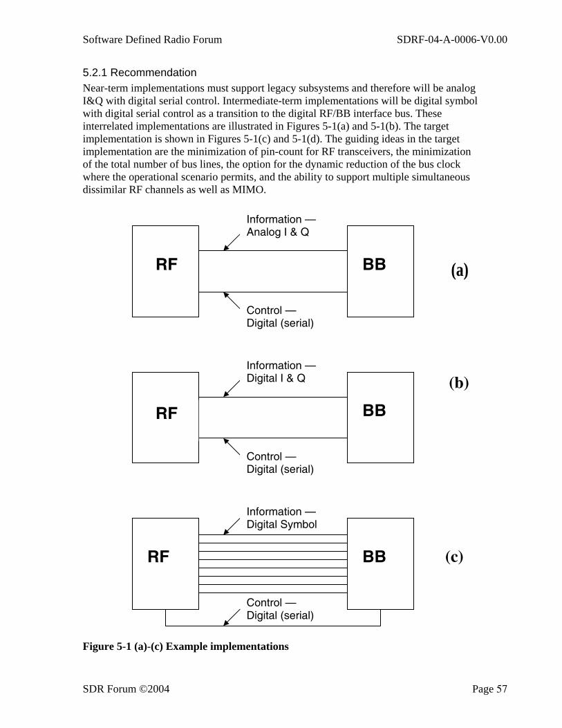
Software Defined Radio Forum SDRF-04-A-0006-V0.00
SDR Forum ©2004 Page 57
5.2.1 Recommendation Near-term implementations must support legacy subsystems and therefore will be analog I&Q with digital serial control. Intermediate-term implementations will be digital symbol with digital serial control as a transition to the digital RF/BB interface bus. These interrelated implementations are illustrated in Figures 5-1(a) and 5-1(b). The target implementation is shown in Figures 5-1(c) and 5-1(d). The guiding ideas in the target implementation are the minimization of pin-count for RF transceivers, the minimization of the total number of bus lines, the option for the dynamic reduction of the bus clock where the operational scenario permits, and the ability to support multiple simultaneous dissimilar RF channels as well as MIMO.
Figure 5-1 (a)-(c) Example implementations
RF BB
Information — Digital Symbol
Control — Digital (serial)
(c)
BB
Information — Digital I & Q
Control — Digital (serial)
RF
RF BB
Information — Analog I & Q
Control — Digital (serial)
(a)
(b)

Software Defined Radio Forum SDRF-04-A-0006-V0.00
SDR Forum ©2004 Page 58
Figure 5-1(d): Concept of Digital RF/BB Interface Bus, Interconnect Specific features include:
• Electrical characteristics based on ANSI/TIA/EIA-644 and IEEE 1596.3 SCILVDS with adaptation of parameters suitable for the needs of commercial handsets (low power, short interconnect length).
RF-Tranceiver1 L6F5 (e.g., WLAN)
RF-Tranceiver2 L3F5 (e.g., wide-band cellular)
RF-Tranceiver3 L2F4 (e.g., broadcast service)
RF-Tranceiver4 L1F1 (e.g., narrow-band cellular)
RF-Tranceiver5 L1F1 (e.g., WPAN)
digital L6F5 BB VLSI
CLOCK (F)
RF-
Fron
t-End
/Ant
enna
5 4 3 2 1 0
}RF/BB Interface Bus

Software Defined Radio Forum SDRF-04-A-0006-V0.00
SDR Forum ©2004 Page 59
• Bus-type architecture with per line configuration options for transmit/receive termination, and point-to-point or multi-drop operation. This feature is intended to support line multiplex in the sense that the digital BB VLSI can allocate a subgroup of bus lines for communication with a specific RF transceiver at a given time.
• Any RF transceiver IC is required to support only the number of bus lines necessary to carry the data rate for its intended modes of operation. This may be fewer lines than supported by the digital BB VLSI.
• Provision for time multiplex operation within subgroups of bus lines. This is intended to support both multiple sources and destinations and reversal of up-link/down-link operation in time multiplex mode.
• Allowance for different bus clocks (e.g., some multiples of a readily available system clock) so as to allow for a combination of low-end and high-end ICs (avoiding overdesign of interface circuitry).
• Introduction of classes with respect to maximum supported bus clock. An RF transceiver intended for operation with low data rates may eventually support a lower class than the digital baseband VLSI only.
• Protocol for configuration of the above features, chip addressing and exchange of data format information.
These features support modular design, as depicted in the examples of Figure 5-1(d). The number of separate RF transceivers in this figure may seem exaggerated; they were included merely for the purpose of clarity. It is assumed in this example that some of the RF transceivers (e.g., #2, #3, and #5) may be operated in parallel, whereas operation of others (e.g., #1 and #2) is mutually exclusive. The modular concept would still allow operating the latter in parallel if the digital BB VLSI offers more bus lines so as to put RF transceivers #1 and #2 on separate groups of lines (or, alternatively, with a higher bus clock, of course). Each RF transceiver supports only as many bus lines and a maximum bus clock as necessary for its intended operation. A classification of interfaces is indicated in the form L#nF#m where #n is the number of bus lines and #m the multiple of the basic clock frequency F supported by the interface.
Possible line and time multiplex options are suggested by Figure 5-2, which is an example of one possible implementation of a symbol interface. It is presented here to assist in understanding the conceptual structure. The specification of the signals shown in Figure 5-2 is an open item staged for further work. Within the limits set by data rates and permissible latencies due to data buffering, the data transfer can be organized into time multiplex patterns separately for different subgroups of lines. Provision for this feature contributes to the minimization of pin count and bus lines.
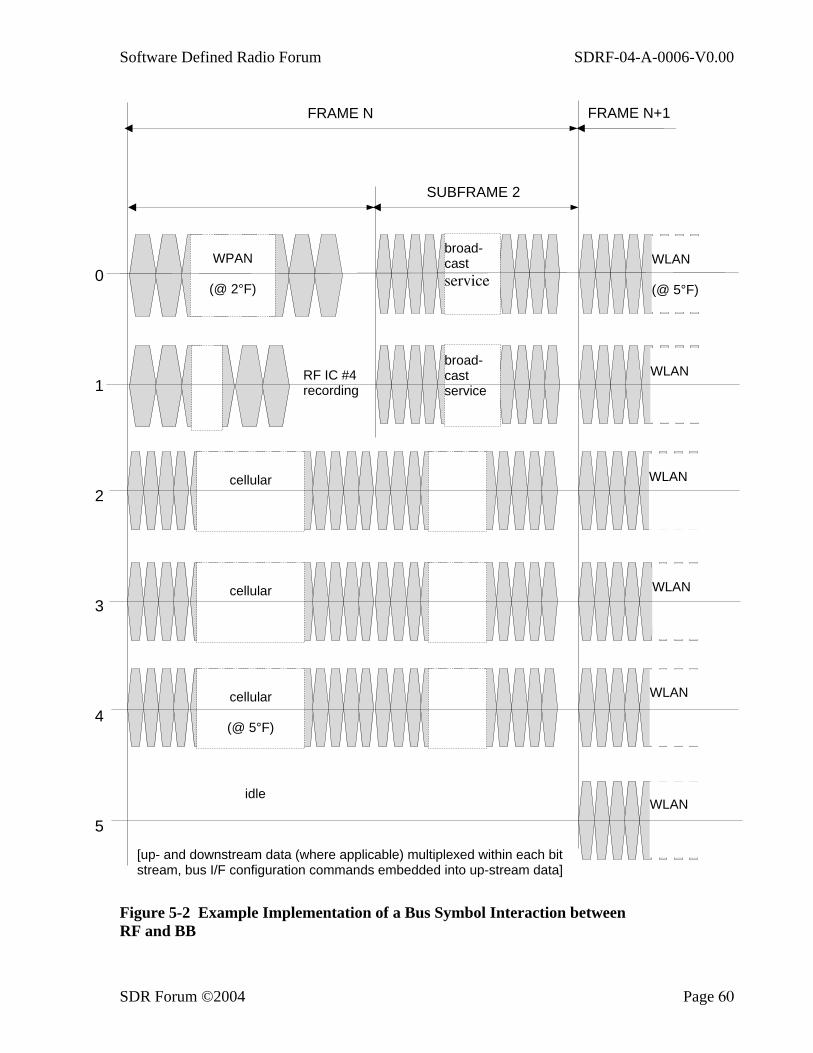
Software Defined Radio Forum SDRF-04-A-0006-V0.00
SDR Forum ©2004 Page 60
Figure 5-2 Example Implementation of a Bus Symbol Interaction between RF and BB
cellular
cellular
cellular
(@ 5°F)
WPAN
(@ 2°F)
broad-cast service
broad-cast service
RF IC #4 recording
idle
WLAN (@ 5°F)
WLAN
WLAN
WLAN
WLAN
WLAN
[up- and downstream data (where applicable) multiplexed within each bit stream, bus I/F configuration commands embedded into up-stream data]
0
1
2
3
4
5
SUBFRAME 2
FRAME N FRAME N+1

Software Defined Radio Forum SDRF-04-A-0006-V0.00
SDR Forum ©2004 Page 61
A. Introduction to the Appendices The following two appendices (B and C) provide background technical information on how the term API is used in this document, including details of how SDR APIs are intended to work. This is followed by the final appendix (D), which describes message and parameter formats for implementing some of the most critical functions required to implement SDR handsets.
Software Defined Radio Forum SDRF-04-A-0006-V0.00
SDR Forum ©2004 Page 62
B. Frameworks and Design Patterns This appendix introduces a mechanism for overall system design that follows a process based on the use of different views of the system to completely describe its operation on several different levels. Successful implementation of this method enables the designer to describe and manage the relationships among the different system views (Figure B-1). The system views are defined as follows: Use Case view, Logical view, Component view, and Deployment view. Descriptors used to specify system operation include: use cases, actors, classes, objects, states, relationships, and interactions.
• The Use Case View expresses the requirements of a system (or a subsystem) in terms of scenarios, use cases, in which the system interacts with its environment, the actors. A scenario is flow or sequence of interactions between the system and its environment.
• The Logical View identifies the conceptual entities of the system, usually as objects and classes with attributes and operations. It also describes the relationships among these entities, and their dynamic behavior in terms of states, state transitions, scenarios etc.
• The Component View describes the implementation units of a system. Components may be hardware or software or combinations thereof. Components have defined interfaces, which are described in the component view as well.
• The Deployment View describes a specific configuration, in terms of processors, devices, and communication mechanisms. This view also allocates the Components from the Component View to its nodes (processors) for a specific instantiation of a system.
Diagrams are used to delineate the relationships among views and relationships among the elements within each view. Each view describes the way that the different elements of the view relate to one another; this is called a framework for the design. Taken together, these views and descriptions provide a means to visualize and manipulate the model's items and their properties to ensure that a complete description of the desired system operation is specified at each level. There is a many-to-many relationship among the elements of each view and the elements of the other views. The relationships of the elements of one view as related to the other views is important but not easy to describe.
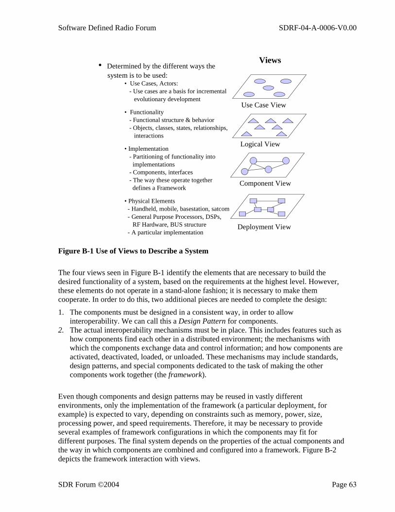
Software Defined Radio Forum SDRF-04-A-0006-V0.00
SDR Forum ©2004 Page 63
Views• Determined by the different ways the system is to be used:
• Use Cases, Actors: - Use cases are a basis for incremental
evolutionary development
• Functionality - Functional structure & behavior - Objects, classes, states, relationships, interactions
• Implementation - Partitioning of functionality into
implementations - Components, interfaces - The way these operate together defines a Framework
• Physical Elements - Handheld, mobile, basestation, satcom - General Purpose Processors, DSPs,
RF Hardware, BUS structure - A particular implementation
Use Case View
Logical View
Component View
Deployment View
Figure B-1 Use of Views to Describe a System
The four views seen in Figure B-1 identify the elements that are necessary to build the desired functionality of a system, based on the requirements at the highest level. However, these elements do not operate in a stand-alone fashion; it is necessary to make them cooperate. In order to do this, two additional pieces are needed to complete the design:
1. The components must be designed in a consistent way, in order to allow interoperability. We can call this a Design Pattern for components.
2. The actual interoperability mechanisms must be in place. This includes features such as how components find each other in a distributed environment; the mechanisms with which the components exchange data and control information; and how components are activated, deactivated, loaded, or unloaded. These mechanisms may include standards, design patterns, and special components dedicated to the task of making the other components work together (the framework).
Even though components and design patterns may be reused in vastly different environments, only the implementation of the framework (a particular deployment, for example) is expected to vary, depending on constraints such as memory, power, size, processing power, and speed requirements. Therefore, it may be necessary to provide several examples of framework configurations in which the components may fit for different purposes. The final system depends on the properties of the actual components and the way in which components are combined and configured into a framework. Figure B-2 depicts the framework interaction with views.

Software Defined Radio Forum SDRF-04-A-0006-V0.00
SDR Forum ©2004 Page 64
ComponentsFramework
DesignPatterns
Figure B-2 Framework Interaction with Views

Software Defined Radio Forum SDRF-04-A-0006-V0.00
SDR Forum ©2004 Page 65
C. Application Program Interfaces (APIs) This document provides high-level descriptions of the SDRF architecture, provides for alternative views of that architecture, and recognizes that the information known about the system may vary over time or that differing perspectives may be needed. The term “architecture” as used herein is defined as the organizational structure of a system, identifying its components, their interfaces, and a concept of execution among them:
• Components are the named “pieces” of design and/or actual entities of the system and comprise one or more modules of software, firmware, and/or hardware.
• Interfaces are the relationships among component modules in which the modules share, provide, or exchange data.
• Concept of execution represents the dynamic relationships of the modules. It can include such descriptions as flow of execution control, information flow, dynamically controlled sequencing, state transition diagrams, timing diagrams, priorities among units, and handling of interrupts, among others.
This appendix is concerned with the development of Application Program Interfaces to define SDRF standard devices. Section C.1. defines and explains the process that is used to create the APIs that form the core of the standards definition. Section C.2 outlines what an API should and should not do. Section C.3 addresses capability management and resource management as well as managing optional components. Sections C.4 and C.5 discuss the design process and its relationship to other processes, respectively. The following appendix, Appendix D, defines a set of generic control messages that can be used as a template to create specific functions by adding functional-specific information. It is envisaged that this template and the functional APIs will create a catalog of functions that SDRF architectures can utilize.
C.1 Background As defined earlier, an API is the interface definition, which is a description of the relationships among related software and/or hardware modules, such as the bi-directional flow of data and control information. It is neither a lump of code nor a program nor an application. An API describes the relationships of modules, not the implementation of those relationships. In many ways, this causes a slight problem because an API is an abstraction and not a physical entity.
This section provides a generic framework for the definition of such APIs. The objective is to provide a common set of rules, guidelines, and definitions that will form the basis for defining software interfaces. The term Application Program Interface is used here to mean the interface definition. It provides levels of abstraction to capture and refine the interface design information from general concepts to implementation-specific details.
C.1.1 Specifying the System One of the classic problems faced in any complex project or design is the failure to scope out and understand the complete amount of work that is involved. Too often, the amount of effort involved is grossly underestimated—especially in the areas of software and the time it
Software Defined Radio Forum SDRF-04-A-0006-V0.00
SDR Forum ©2004 Page 66
takes to specify and integrate the system. Similar problems can also be encountered when extending or enhancing existing systems. The difficulty facing the industry today is related to a changeover within radio design that is blurring the system in terms of whether software or hardware is used for the implementation. Although the term API is used to describe these interfaces, it has come from a purely software background, and on first inspection is not applicable to other interfaces such as hardware buses and form factors. The problem is that technology that is implemented today by using programmable devices and software may be implemented tomorrow in hardware. To allow the successful replacement of modules by different solutions—for example, to replace a software-based module by a hardware version—the interfaces that define the boundary of the module must be designed in such a way that the interface does not imply or exclude a potential implementation. If it does, then its appeal and thus its ability to attract products that conform and thus be reused will be limited.
This means that the development of APIs actually is the development of interfaces, which may be software or hardware or a combination of the two. The term API within this discussion should be interpreted as simply an interface document and therefore applicable to any part of a system, such as a bus, form factor, and so on. It is not simply restricted to software.
The “chocolate chip cookie” approach2 to system specification must be avoided. A good
way to do this in the initial stages is to create an interface layer diagram that defines the components and how they interface. It should be remembered that this type of diagram is not a replacement for other modeling techniques, such as data flow diagrams or structured analyses, but does provide an excellent starting point on which to build. This type of diagram identifies not only the components but the interface mechanisms and definitions that are often overlooked. The model uses only two fundamental terms to explain all the various layers of software and their interfaces.
C.1.2 Software and Hardware Modules and Their Interfaces In general, a module is the actual implementation that uses the interfaces to receive information, process it, and output it. As far as the interfaces go, they should be independent of the implementation (i.e., the module that is sandwiched between them).
A good way to see the interaction between modules and interfaces is through layer diagrams in which the various layers are depicted as either interfaces or modules. To be consistent throughout this document, the symbols in Figure C-1 are allocated to both interfaces and modules. Figure C-1 shows the correct use of the design symbols for the modules and interface. Figure C-2 shows two uses of design symbols in which the modules and interfaces are incorrectly layered.
2 This is where individual modules—the so-called “chocolate chips”—are identified and are assumed to make
up the complete system without taking into account the amount of integration and other system components—the “cookie mixture”—needed to complete the system.
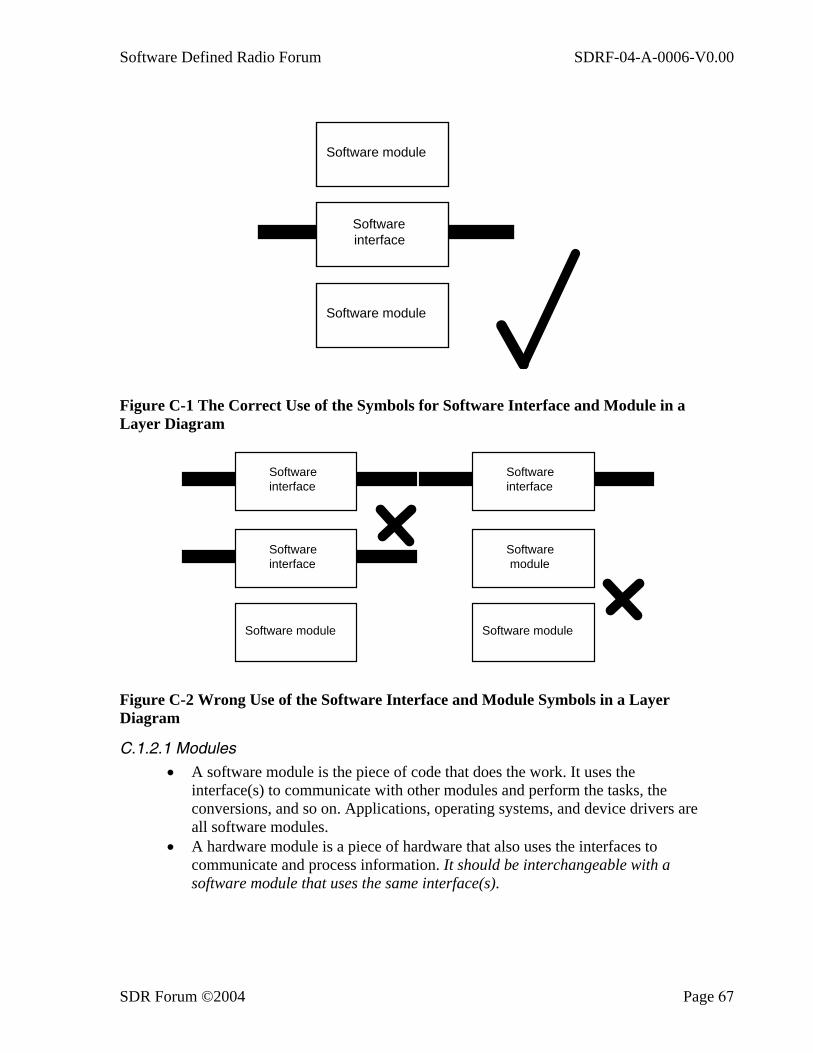
Software Defined Radio Forum SDRF-04-A-0006-V0.00
SDR Forum ©2004 Page 67
Software module
Software interface
Software module
Figure C-1 The Correct Use of the Symbols for Software Interface and Module in a Layer Diagram
Software interface
Software module
Software interface
Software module
Software module
Software interface
Figure C-2 Wrong Use of the Software Interface and Module Symbols in a Layer Diagram
C.1.2.1 Modules
• A software module is the piece of code that does the work. It uses the interface(s) to communicate with other modules and perform the tasks, the conversions, and so on. Applications, operating systems, and device drivers are all software modules.
• A hardware module is a piece of hardware that also uses the interfaces to communicate and process information. It should be interchangeable with a software module that uses the same interface(s).

Software Defined Radio Forum SDRF-04-A-0006-V0.00
SDR Forum ©2004 Page 68
These definitions lead to the essential golden rule: As modules and interfaces are layered together to create the overall system structure, they must alternate. Two adjacent module or interface layers are not allowed.
To use an analogy of a car, the driver and the car are both software modules and they can only work if there is a software interface layered between them. With a car, the interface is the knowledge that the middle pedal is the brake for cars with manual gear boxes, and moving the steering wheel to the right will make the car go to the right. The knowledge or interface does not turn the wheel or move the wheels; that is done by the driver and the car.
C.1.2.2 Interfaces It is virtually impossible to define a set of APIs that cover all aspects without causing confusion or precluding new ideas. In practice, a complete set of interfaces needs to define several tiers to provide different levels of compatibility: It is important that the interfaces are understood and adhered to. If they are not, then the system will not work correctly and it will be difficult to change individual components. Returning to the car analogy, imagine the chaos if the brake and gas pedals were swapped around!
Before determining what makes a good interface, it is important to reinforce the definitions of the interfaces. Previously, we defined three tiers of interfaces, which have the following generic requirements:
• A Functional-Level Interface or API It describes the message and its contents. It does not describe how the message is transported. It is only a document! It must be unambiguous and have only one interpretation.
• A Transport-Level Interface It describes how messages are passed and does not describe the content. Again, it is only a document! Again, it must be unambiguous and have only one interpretation.
• A Physical-Level Interface It describes how physical components fit together (e.g., form factor, connectors,
power supplies, and so on). Again, it is only a document! Again, it must be unambiguous and have only one interpretation.
C.2 What Should an API or Interface Do? The starting point in answering this question is to define what an interface should NOT do.
• It should NOT combine information and control flows. Information and control flows often need different interfaces and requirements, and combining them can cause conflict and compromise. For example, a RF module may provide a digital control interface but require analog transmit and receive signals. It is clear in this case that these interfaces should be kept separate. However, if the analog interface is replaced by a digital one, the boundary is less clear. The case for keeping interfaces separate is clear: although both interfaces are digital, the control interface is less time-critical than

Software Defined Radio Forum SDRF-04-A-0006-V0.00
SDR Forum ©2004 Page 69
for the RX/TX information interface, and therefore does not need the high-bandwidth interface that Rx/Tx information requires. Control data are frequently asynchronous in nature, and imposing this on the Rx/Tx information bus can cause the Rx/Tx information to also become slightly asynchronous. This can be overcome by buffering, but this then introduces delay. There also is the question of how to route the two signals down the same bus. The end result is a compromised design, which can be avoided by keeping things simple and separate.
In addition to these practical reasons, the explicit separation of control and information flow is normally required for a proper security design.
• It should NOT have two or more APIs or interfaces controlling a single resource without resource management.
This is often a major challenge for any programmable device in which a resource such as processing, memory, or an I/O device can be controlled or shared between two independent controls. Although not necessarily a problem, this structure should be carefully examined to see if a form of resource management is needed to resolve conflicts.
• It should NOT allow applications to bypass intermediate level APIs directly to lower levels.
The API should be independent of any other APIs below it so that its integrity is not compromised. Preventing the combination of simultaneous upper- and lower-level access also prevents potential compatibility problems. This is not intended to prevent the successful concatenating of modules together.
• It should NOT be under-specified. APIs and interfaces need to be designed so that they can support future developments. This can be helped by the provision of extension mechanisms, which allow the orderly expansion of an interface while maintaining compatibility with previous versions.
• It should NOT have knowledge of the implementation or any APIs below it. The definition of one API should not be dependent on the definition of another API. This restriction is necessary to provide a true black-box level of independence below an API or interface.
A good interface WILL have the following characteristics:
• It will be written so that it is understandable and testable. Multiple descriptions or views may be necessary to adequately define an API. For example, graphs, figures, diagrams, and text may be combined to present a complete picture of the API. The API must be testable so that compliance can be verified.
• It will have reasonable granularity within the system partitioning. Granularity is important when considering re-use and providing an attractive environment for suppliers. The SDRF architectures described in this report provide high-level descriptions of SDR functions, such as modems and RF. When these functions are examined in detail, it is clear that they consist of several key technology components. For example, if the API is defined for a modem function as a whole, then the supplier of modem
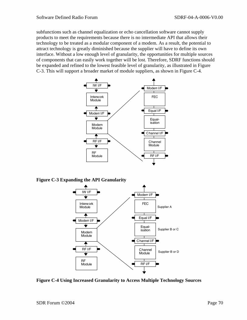
Software Defined Radio Forum SDRF-04-A-0006-V0.00
SDR Forum ©2004 Page 70
subfunctions such as channel equalization or echo cancellation software cannot supply products to meet the requirements because there is no intermediate API that allows their technology to be treated as a modular component of a modem. As a result, the potential to attract technology is greatly diminished because the supplier will have to define its own interface. Without a low enough level of granularity, the opportunities for multiple sources of components that can easily work together will be lost. Therefore, SDRF functions should be expanded and refined to the lowest feasible level of granularity, as illustrated in Figure C-3. This will support a broader market of module suppliers, as shown in Figure C-4.
RF I/F
RFModule
Modem I/F
ModemModule
IW I/F
InterworkModule
Channel I/F
ChannelModule
Equal I/F
Equal-isation
FEC
RF I/F
Modem I/F
Figure C-3 Expanding the API Granularity
RF I/F
RFModule
Modem I/F
ModemModule
IW I/F
InterworkModule
Channel I/F
ChannelModule
Equal I/F
Equal-isation
FEC
RF I/F
Modem I/F
Supplier A
Supplier B or C
Supplier B or D
Figure C-4 Using Increased Granularity to Access Multiple Technology Sources
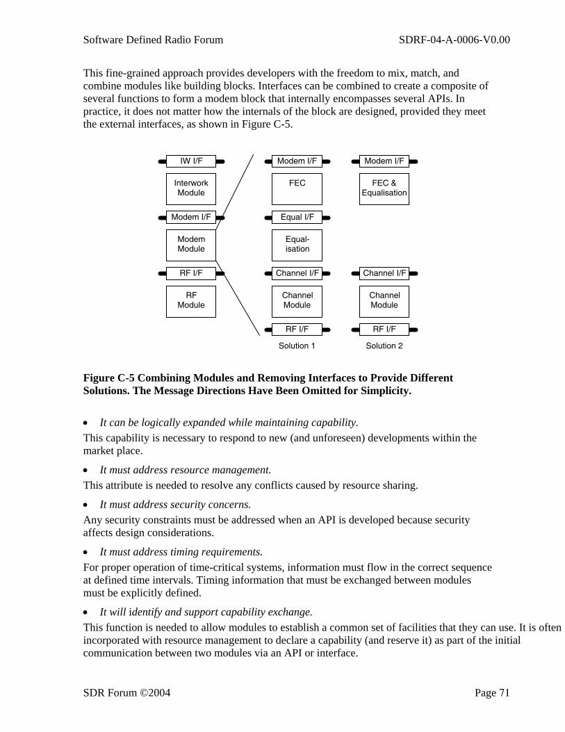
Software Defined Radio Forum SDRF-04-A-0006-V0.00
SDR Forum ©2004 Page 71
This fine-grained approach provides developers with the freedom to mix, match, and combine modules like building blocks. Interfaces can be combined to create a composite of several functions to form a modem block that internally encompasses several APIs. In practice, it does not matter how the internals of the block are designed, provided they meet the external interfaces, as shown in Figure C-5.
RF I/F
RF Module
Modem I/F
Modem Module
IW I/F
Interwork Module
Channel I/F
Channel Module
Equal I/F
Equal-isation
FEC
RF I/F
Modem I/F
Channel I/F
Channel Module
FEC & Equalisation
RF I/F
Modem I/F
Solution 1 Solution 2
Figure C-5 Combining Modules and Removing Interfaces to Provide Different Solutions. The Message Directions Have Been Omitted for Simplicity.
• It can be logically expanded while maintaining capability. This capability is necessary to respond to new (and unforeseen) developments within the market place.
• It must address resource management. This attribute is needed to resolve any conflicts caused by resource sharing.
• It must address security concerns. Any security constraints must be addressed when an API is developed because security affects design considerations.
• It must address timing requirements. For proper operation of time-critical systems, information must flow in the correct sequence at defined time intervals. Timing information that must be exchanged between modules must be explicitly defined.
• It will identify and support capability exchange. This function is needed to allow modules to establish a common set of facilities that they can use. It is often incorporated with resource management to declare a capability (and reserve it) as part of the initial communication between two modules via an API or interface.
Software Defined Radio Forum SDRF-04-A-0006-V0.00
SDR Forum ©2004 Page 72
C.3 Management
C.3.1 Capability Management Capability exchange is a well-known technique used to allow two modules of differing capabilities to communicate successfully by using a single API. It is used in the Telephone API (TAPI) specification and in the H.320 video conferencing standards. It is very closely related to resource management (see the next section) because the declaration of a particular capability, by default, will assume that resources are available.
The first question that typically arises when capability exchange is mentioned is, “Why do you need it if you have a defined interface?” The following three scenarios provide good reasons why an interface should be expandable and therefore require some way of exactly declaring the capabilities of module(s) on either side of an interface.
• Scenario 1—Coping with interface revisions and enhancements Although it is the intention of all concerned to define a single standard, the reality is that this is rarely the case. As new technology becomes available, or as errors appear, standards will need revision or enhancement. If this happens, there is a normal requisite for backward compatibility to allow the maximum reuse of legacy components. The problem facing new components is identifying which revision the component on the other side of the interface is using. This is where the capability exchange is important.
• Scenario 2—Allowing the use of proprietary extensions Companies in the PC world often offer combinations of interfaces or APIs to their products. This allows users to choose between an open standard or proprietary implementation, depending on the differing attributes that the interfaces offer. For example, a PC graphics card may reproduce the VGA register set as well as offer a special Windows driver that accesses the hardware differently and gives improved performance.
Proprietary additions may range from simple extensions to a standard interface to a completely different interface. Obviously, using these proprietary additions locks in the owner to a specific implementation, but this may be acceptable, and even preferable to the owner. In many cases, especially in the PC world, proprietary standards have quickly become de facto industry standards. It is important, however to provide a standardized way of adding these extensions and recognizing when they can successfully be used between two modules using a common API.
• Scenario 3—Adjusting support to match the available resources In this case, the capability exchange is used to restrict an interface to support those functions for which resources are available. This is necessary when the module that uses the interface shares resources with other modules such as processing time and power, memory, peripherals, and so on.
C.3.2 Resource Management Resource management is required to resolve problems caused by the re-use of resources without declaring any potential change in capabilities. In reality, many wireless systems hide the resource management issue because resource management is handled when the system is designed, integrated, and tested. This static resource management effectively

Software Defined Radio Forum SDRF-04-A-0006-V0.00
SDR Forum ©2004 Page 73
dispenses with any need for its inclusion within an API because the resources are always reserved for the appropriate use.
A good example of this use is the GSM handset. It can often support a range of different speech encoders with differing DSP MIPs and memory requirements. When the simplest encoder is used, the additional resources that the most complex encoder needs are not used but are available for use at a moment’s notice. If the handset is more sophisticated, the unused resources can be allocated to a different task, such as a video decode. However, this reallocation then creates a dilemma: the handset has declared a capability to support a more complex speech encoder but is using the other resources to support another function. Thus, if both parties have declared that they can use Ñ, and the other party decides to change to the complex encoder Ñ, the resources required to support the new encoder are not available without stopping the video decoding.
A simple and effective, albeit inefficient, way of addressing this problem is to adopt a “declare it and reserve it” policy by which any declared capability automatically reserves the resources necessary to support it, even though they may not necessarily be used at the time and stand idle.
A more efficient method is to expand the policy to a “declare it, reserve it, negotiate, and re-declare it” policy. In this scheme, unused resources that have been declared and reserved can be negotiated away to another use, providing that the current capabilities are re-exchanged and downgraded to reflect the change in available resources.
Both of these techniques are used in the H.320 videoconference standards, and the capability exchange mechanism that is described in these documents could form the basis of a key component for the SDRF APIs. They basically work by exchanging tables of information describing spec revisions, options, and any proprietary extensions that might be available. One party then determines a common subset, and this is used to restrict the possible API calls to those that both parties understand.
Resource management is also needed in other areas apart from the obvious one to determine the exact level of communication through an API. Another common use of the technique occurs when two modules communicate with a single module in a two-into-one configuration, as shown in Figure C-6. Here the resource management is implicit and not immediately obvious. Modules A and B have independent control flows but both of them interface to the same module C through API C. There is a potential risk of conflict with API C. If this interface has been designed assuming a single input, then it cannot cope with the two separate flows shown. It may receive conflicting commands or information. If so, which one does it respond to and when?
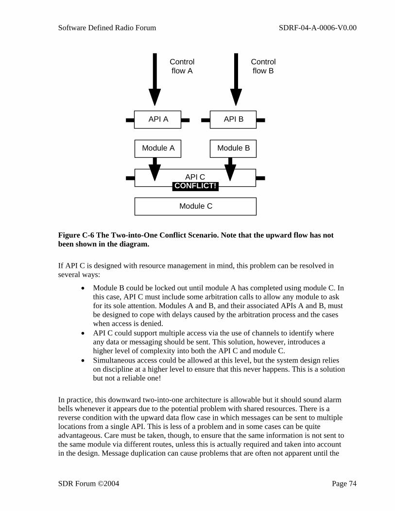
Software Defined Radio Forum SDRF-04-A-0006-V0.00
SDR Forum ©2004 Page 74
API A API B
Module A Module B
API C
Module C
Controlflow A
Controlflow B
CONFLICT!
Figure C-6 The Two-into-One Conflict Scenario. Note that the upward flow has not been shown in the diagram.
If API C is designed with resource management in mind, this problem can be resolved in several ways:
• Module B could be locked out until module A has completed using module C. In this case, API C must include some arbitration calls to allow any module to ask for its sole attention. Modules A and B, and their associated APIs A and B, must be designed to cope with delays caused by the arbitration process and the cases when access is denied.
• API C could support multiple access via the use of channels to identify where any data or messaging should be sent. This solution, however, introduces a higher level of complexity into both the API C and module C.
• Simultaneous access could be allowed at this level, but the system design relies on discipline at a higher level to ensure that this never happens. This is a solution but not a reliable one!
In practice, this downward two-into-one architecture is allowable but it should sound alarm bells whenever it appears due to the potential problem with shared resources. There is a reverse condition with the upward data flow case in which messages can be sent to multiple locations from a single API. This is less of a problem and in some cases can be quite advantageous. Care must be taken, though, to ensure that the same information is not sent to the same module via different routes, unless this is actually required and taken into account in the design. Message duplication can cause problems that are often not apparent until the

Software Defined Radio Forum SDRF-04-A-0006-V0.00
SDR Forum ©2004 Page 75
system integration phase. In general, the upward scenarios can be used with care. If the messages and data are independent, there is no problem. If they are not, care must be exercised to prevent a duplicated message arriving via different routes and being treated as two separate messages. This may mean that some form of resource management is needed to remove the conflict by either filtering or re-routing the messages.
C.3.3 Managing Optional Components With many radio systems, particularly mobile systems, several user interfaces can have different levels of control over a single radio system. This creates a problem similar to the two-into-one scenario discussed in the previous section. The diagram in Figure C-7 shows such a system with three interfaces providing three separate control paths into the radio. For this system to have any chance to work, the radio system must contain some resource management to reconcile which control path takes command.
Figure C-7 The Multiple Control Path Problem (note that the upward flow is not shown in the diagram)
This type of system poses a problem for anyone defining an API for the radio system because the user interfaces and control paths are extremely varied. The solution is to bring out resource management as a separate layer, as shown in Figure C-8. The three control interfaces are still present and pass commands via the radio user interface almost as before—almost, because there are also resource management commands associated with the interface. These commands use capability exchanges and other information to determine who has actual control of the radio. This could be fixed and hard coded or dynamic and vary with circumstances. By using a common command interface and a capability exchange to restrict each interface to a particular subset, different categories of access can be quickly defined and changed if needed. For example, network interfaces 1 and 2 could be restricted
Local interface API
Network interface 1 API
Network interface 2 API
Local interface module
Network interface 1 module
Network interface2 module
Local interfaceRadio user
interface API
The radio system
Control path 1
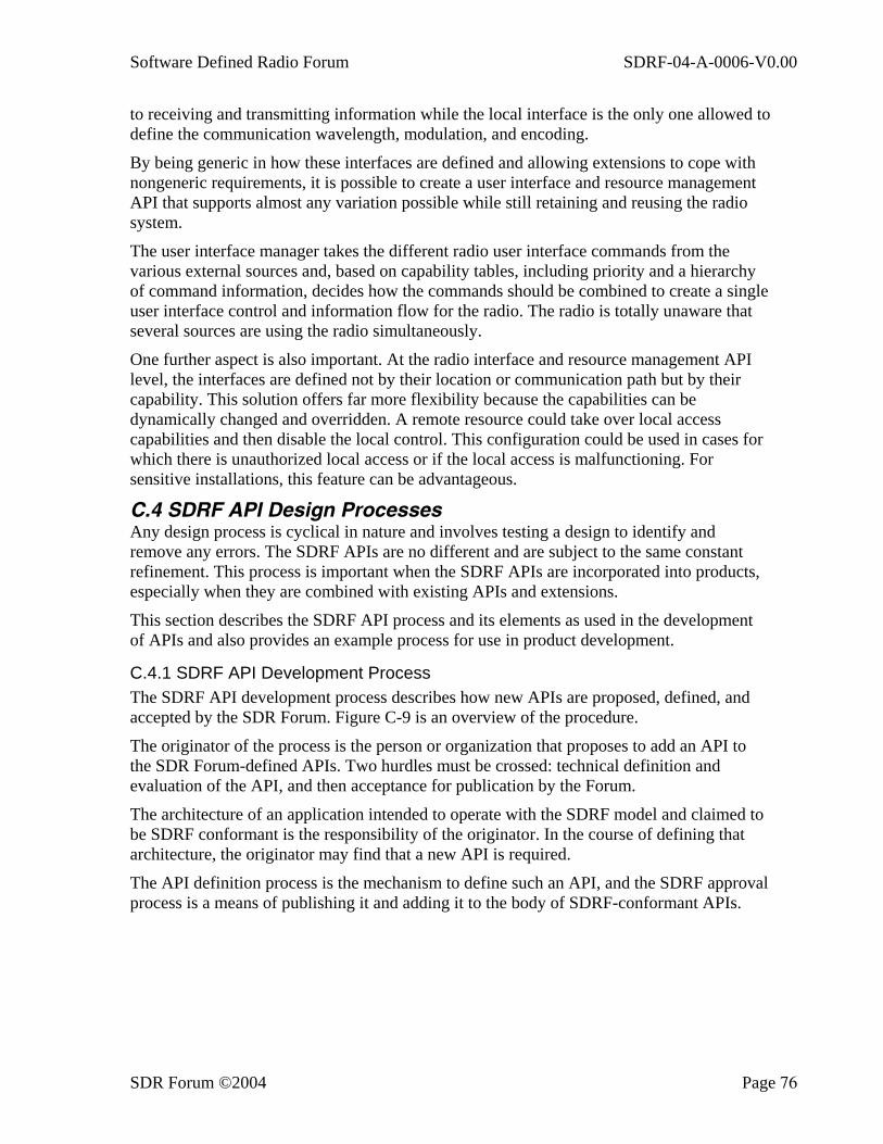
Software Defined Radio Forum SDRF-04-A-0006-V0.00
SDR Forum ©2004 Page 76
to receiving and transmitting information while the local interface is the only one allowed to define the communication wavelength, modulation, and encoding.
By being generic in how these interfaces are defined and allowing extensions to cope with nongeneric requirements, it is possible to create a user interface and resource management API that supports almost any variation possible while still retaining and reusing the radio system.
The user interface manager takes the different radio user interface commands from the various external sources and, based on capability tables, including priority and a hierarchy of command information, decides how the commands should be combined to create a single user interface control and information flow for the radio. The radio is totally unaware that several sources are using the radio simultaneously.
One further aspect is also important. At the radio interface and resource management API level, the interfaces are defined not by their location or communication path but by their capability. This solution offers far more flexibility because the capabilities can be dynamically changed and overridden. A remote resource could take over local access capabilities and then disable the local control. This configuration could be used in cases for which there is unauthorized local access or if the local access is malfunctioning. For sensitive installations, this feature can be advantageous.
C.4 SDRF API Design Processes Any design process is cyclical in nature and involves testing a design to identify and remove any errors. The SDRF APIs are no different and are subject to the same constant refinement. This process is important when the SDRF APIs are incorporated into products, especially when they are combined with existing APIs and extensions.
This section describes the SDRF API process and its elements as used in the development of APIs and also provides an example process for use in product development.
C.4.1 SDRF API Development Process The SDRF API development process describes how new APIs are proposed, defined, and accepted by the SDR Forum. Figure C-9 is an overview of the procedure.
The originator of the process is the person or organization that proposes to add an API to the SDR Forum-defined APIs. Two hurdles must be crossed: technical definition and evaluation of the API, and then acceptance for publication by the Forum.
The architecture of an application intended to operate with the SDRF model and claimed to be SDRF conformant is the responsibility of the originator. In the course of defining that architecture, the originator may find that a new API is required.
The API definition process is the mechanism to define such an API, and the SDRF approval process is a means of publishing it and adding it to the body of SDRF-conformant APIs.
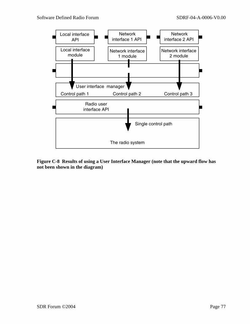
Software Defined Radio Forum SDRF-04-A-0006-V0.00
SDR Forum ©2004 Page 77
Figure C-8 Results of using a User Interface Manager (note that the upward flow has not been shown in the diagram)
Local interfaceUser interface manager
Local interface API
Network interface 1 API
Network interface 2 API
Local interface module
Network interface1 module
Network interface 2 module
Local interface
The radio system
Control path 1 Control path 2 Control path 3
Local interfaceRadio user
interface API
Single control path
Software Defined Radio Forum SDRF-04-A-0006-V0.00
SDR Forum ©2004 Page 78
Architecture
Need New API ?
Module API Development
(MAD) Process
SDRFApprovalProcess
Publish No
Yes
Accept
Refer Back to
Originator Originator
Reject
Figure C-9 Context for the API Development Process
C.4.2 SDRF API Definition Process The need for a new API arises as the result of an application. The API definition process is depicted in Figure C-10.
The steps in the definition process are as follows:
• Product architecture The architecture is based on application requirements and will contain sufficient interface and behavioral information to provide that all API definitions—including any extensions to the SDRF APIs or proprietary interfaces or wrappers—are unambiguous.
• Human API definition This is the textual description of the APIs needed to support the product architecture. It is a manual process but can be facilitated in several ways. The SDRF documentation through its API design guide and examples, provides detailed guidance on how to define and create APIs.
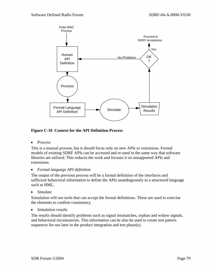
Software Defined Radio Forum SDRF-04-A-0006-V0.00
SDR Forum ©2004 Page 79
SimulationResults
HumanAPI
Definition
OK?
Formal LanguageAPI Definition Simulate
Process
Enter MADProcess
Proceed toSDRF Acceptance
No /Problems
Yes
Figure C-10 Context for the API Definition Process
• Process This is a manual process, but it should focus only on new APIs or extensions. Formal models of existing SDRF APIs can be accessed and re-used in the same way that software libraries are utilized. This reduces the work and focuses it on unsupported APIs and extensions.
• Formal language API definition The output of the previous process will be a formal definition of the interfaces and sufficient behavioral information to define the APIs unambiguously in a structured language such as HML.
• Simulate Simulation will use tools that can accept the formal definitions. These are used to exercise the elements to confirm consistency.
• Simulation results The results should identify problems such as signal mismatches, orphan and widow signals, and behavioral inconstancies. This information can be also be used to create test pattern sequences for use later in the product integration and test phase(s).

Software Defined Radio Forum SDRF-04-A-0006-V0.00
SDR Forum ©2004 Page 80
• Results comparison The simulation results are then compared to the original product architecture and checked for any problems. This is likely to involve a combination of a design review approach coupled with the use of automated tools to highlight problems.
If the results are acceptable, then the API can proceed to the SDRF acceptance process.
If the errors are caused by implementation issues (e.g., a missing signal or message), then the human API definition is refined to remove the error and the API development process repeated.
If the errors are fundamental to the design, however, then either the requirements or product architecture must be updated before repeating the process. Because these are the responsibility of the originator, the issue is out of the scope of the API development process and is referred back for resolution.
C.5 Relationships to Noncompliant Processes A primary objective of the SDR Forum is to establish a set of APIs that will provide an open interface into SDRF-compliant systems. This section explores how legacy APIs and the SDRF APIs work together to define the specific APIs to be included in a new development project. Because legacy processes were developed before the APIs were defined, they are likely to be noncompliant.
C.5.1 API Relationships It is important to realize that the SDRF APIs for a software definable or configurable radio are not being developed in isolation. It is therefore also important to include facilities to support both internal and external existing APIs and to provide support for additional facilities necessary to meet the required product specifications. As a result, it is conceivable that there will be many SDRF-compliant radios that will have varying proportions of APIs, depending on the end requirement. This can range from a radio that is completely SDRF-based to one that may have a high-level SDRF interface but relies on existing and/or proprietary interfaces. Figure C-11 displays these relationships as a Venn diagram.
SDRF CHSAPIs
Legacy APIs
Product specifications Product
requirements
Figure C-11 The API Relationship Diagram

Software Defined Radio Forum SDRF-04-A-0006-V0.00
SDR Forum ©2004 Page 81
C.5.1.1 SDRF-CHS APIs SDRF-CHS APIs are those APIs defined by the SDR Forum and used to create a commercial handset framework. In a complete SDRF system, all the published APIs would be used. In a reduced system, some of the APIs may not be used or required. In a hybrid system, some of the APIs may be replaced by legacy or proprietary APIs. This replacement will require some form of conversion between the two environments. This is performed by the wrapper layer, which is located between the respective SDRF and legacy APIs. The wrapper is discussed later in this appendix.
C.5.1.2 Legacy APIs In an ideal world, there is a strong argument that there is no need to support existing or legacy APIs as long as alternatives are available. In a practical world, this may not be achievable, and the desire to use or re-use existing subsystems may have great importance in reducing design costs. This choice, however, relies on the existence of some form of conversion to allow the legacy APIs to communicate with the SDRF environment. It is this conversion that the wrapper performs. Provided the wrapper design and implementation are not prohibitive, it allows SDRF-based systems to be developed by using existing components. Supporting legacy APIs also has other benefits in that it can provide an additional source of design knowledge based on practical experience, which can be used to test the SDRF APIs and identify omissions and discrepancies. For all of these reasons, legacy API support is an essential and important component of the SDRF environment.
C.5.1.3 Product Specifications The third input into the relationship involves product specifications. These will define requirements that may be beyond the SDRF APIs on first inspection but may still require support from SDRF APIs. The specifications may require software download, Therefore, product specification immediately requires the inclusion of the SDRF software download API. It may also require a sophisticated GUI front end for the end user. This is not directly specified in the SDRF APIs but does rely on SDRF messages and information to allow the connection status and other parameters to be displayed. In this example, SDRF APIs will be needed to provide the foundations, but the designer has the freedom to build whatever support is needed on top of them.
As a result, the relative proportions of the three rings in Figure C-11 may (and will) vary, depending on the final product requirements. The overlap of the three rings defines the subset of the requirements for the product. These final proportions, when defined, effectively create product requirements that can be input into the API development process to create and test the API design. The technical report provides sufficient detail to allow an initial set of requirements to be input into the process.
C.5.2 The Wrapper The idea of the wrapper is to provide a conversion process to allow bi-directional communication between two different APIs. The wrapper is a piece of software or hardware that allows modules on either side of it to communicate through their own APIs without knowing that any conversion or modification has taken place.
The wrapper uses the two APIs that it is bridging between as its boundary definitions and then processes the information internally from each API to allow them to work together.
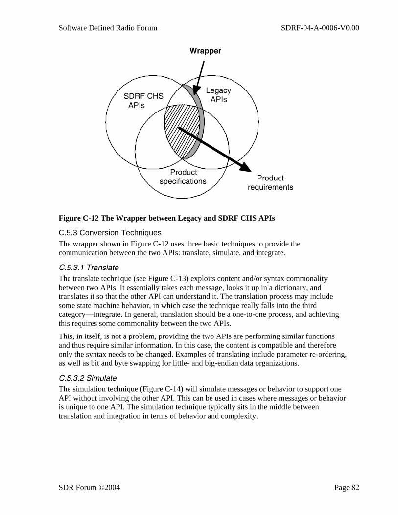
Software Defined Radio Forum SDRF-04-A-0006-V0.00
SDR Forum ©2004 Page 82
Legacy APIs
Product specifications Product
requirements
SDRF CHS APIs
Wrapper
Figure C-12 The Wrapper between Legacy and SDRF CHS APIs
C.5.3 Conversion Techniques The wrapper shown in Figure C-12 uses three basic techniques to provide the communication between the two APIs: translate, simulate, and integrate.
C.5.3.1 Translate The translate technique (see Figure C-13) exploits content and/or syntax commonality between two APIs. It essentially takes each message, looks it up in a dictionary, and translates it so that the other API can understand it. The translation process may include some state machine behavior, in which case the technique really falls into the third category—integrate. In general, translation should be a one-to-one process, and achieving this requires some commonality between the two APIs.
This, in itself, is not a problem, providing the two APIs are performing similar functions and thus require similar information. In this case, the content is compatible and therefore only the syntax needs to be changed. Examples of translating include parameter re-ordering, as well as bit and byte swapping for little- and big-endian data organizations.
C.5.3.2 Simulate The simulation technique (Figure C-14) will simulate messages or behavior to support one API without involving the other API. This can be used in cases where messages or behavior is unique to one API. The simulation technique typically sits in the middle between translation and integration in terms of behavior and complexity.
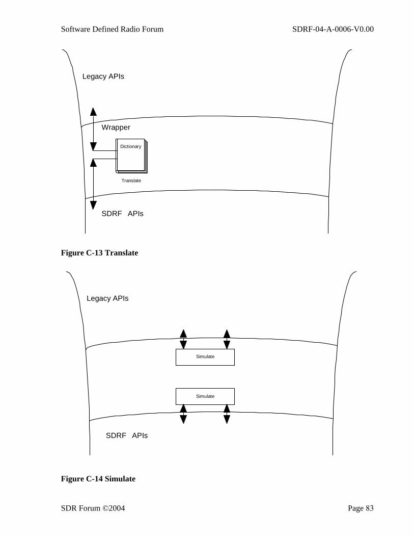
Software Defined Radio Forum SDRF-04-A-0006-V0.00
SDR Forum ©2004 Page 83
Dictionary
Translate
Legacy APIs
SDRF APIs
Wrapper
Figure C-13 Translate
Simulate
Simulate
Legacy APIs
SDRF APIs
Figure C-14 Simulate
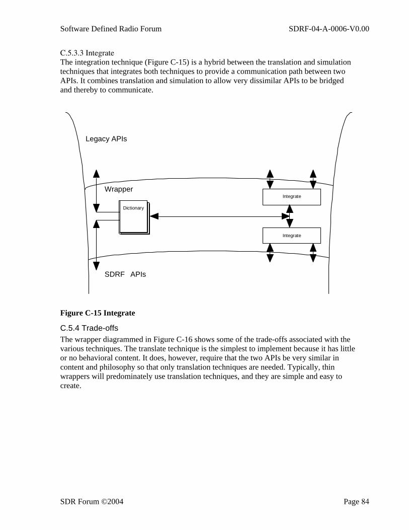
Software Defined Radio Forum SDRF-04-A-0006-V0.00
SDR Forum ©2004 Page 84
C.5.3.3 Integrate The integration technique (Figure C-15) is a hybrid between the translation and simulation techniques that integrates both techniques to provide a communication path between two APIs. It combines translation and simulation to allow very dissimilar APIs to be bridged and thereby to communicate.
Dictionary
Integrate
Integrate
Legacy APIs
SDRF APIs
Wrapper
Figure C-15 Integrate
C.5.4 Trade-offs The wrapper diagrammed in Figure C-16 shows some of the trade-offs associated with the various techniques. The translate technique is the simplest to implement because it has little or no behavioral content. It does, however, require that the two APIs be very similar in content and philosophy so that only translation techniques are needed. Typically, thin wrappers will predominately use translation techniques, and they are simple and easy to create.
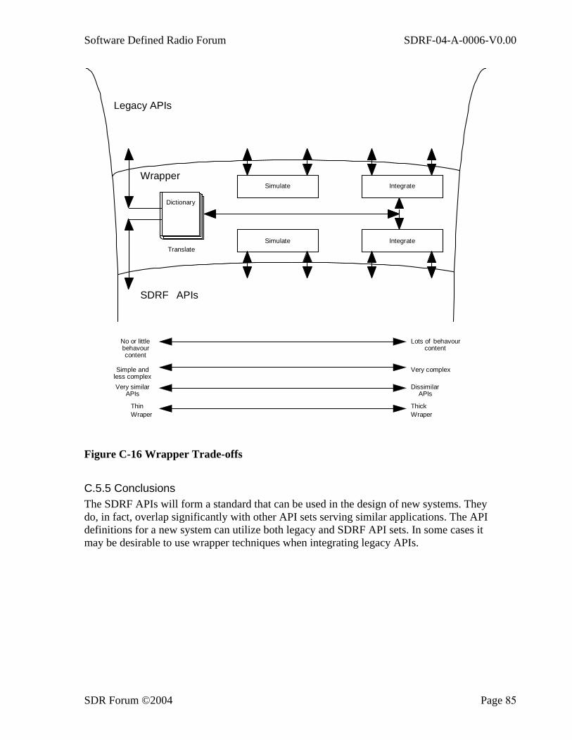
Software Defined Radio Forum SDRF-04-A-0006-V0.00
SDR Forum ©2004 Page 85
Dictionary
Simulate
Simulate
Integrate
IntegrateTranslate
Legacy APIs
SDRF APIs
Wrapper
No or littlebehavourcontent
behavourLots ofcontent
Simple andless complex
Very complex
Very similarAPIs
DissimilarAPIs
ThinWraper
ThickWraper
Figure C-16 Wrapper Trade-offs
C.5.5 Conclusions The SDRF APIs will form a standard that can be used in the design of new systems. They do, in fact, overlap significantly with other API sets serving similar applications. The API definitions for a new system can utilize both legacy and SDRF API sets. In some cases it may be desirable to use wrapper techniques when integrating legacy APIs.
Software Defined Radio Forum SDRF-04-A-0006-V0.00
SDR Forum ©2004 Page 86
D. Message Descriptions for APIs SDR modules use messages as the primary means of exercising control and exchanging information. Messages are of two types: control messages and information messages. Messages flow in accordance with the guidance of the API design guide described earlier. This appendix provides an example of how control messages are used within the SDRF environment and gives specific examples for currently identified control messages. Through this set of examples, this appendix also identifies some of the key problems and proposes some solutions to these issues. These examples reflect a functional perspective but alternatives will be considered. It is anticipated that, wherever possible, the final API specifications will utilize current technologies and standards.
For each API in a system, there is a requirement for a set of messages that allow the module associated with the API(s) to be configured and set up correctly. This set of messages is reasonably generic in that all APIs will require them and will differ only in terms of API-specific information and parameters.
By using these messages, modules can be initialized, started and stopped, enabled and disabled; capabilities can be exchanged; configurations can be adapted; and so on. In addition, support for the replacement, augmentation or switching of facilities is also included to provide the foundation support for software download and hot swappable hardware.
The messages can be used in one of two ways:
• To provide the basic control and set-up, as previously described • To provide support for a switcher module that can intelligently enable/disable
modules to radically change the functionality of the overall system This last method can be used in multi-band and/or multi-mode systems, for example, to select a particular service or waveband. The intelligence is contained within the switcher function, but it can use the same APIs without having to change them.
D.1 Messages This section describes the control messages that are needed to control and configure a module via its API. It is envisaged that these messages will appear in all API definitions along with additional messages to control the functionality of the API. These messages can be used by a module to implement service switching functions within a multi-band and/or multi-mode phone.
D.1.1 Message Acknowledgment Each message is acknowledged by a status word(s), which confirms that the destination has correctly received the message, acted on its contents, and is replying with the current status (Figure D-1). This provides detailed information not only to allow the traditional “ack/nack” protocol but also to debug and for system integration where a deeper insight is needed. Status words sent in direct reply to a message are referred to as solicited status information (SSI).

Software Defined Radio Forum SDRF-04-A-0006-V0.00
SDR Forum ©2004 Page 87
In addition, status information can be returned without any initiating message if the module status has changed. For example, a detected error can be reported by sending a suitable status word. These messages are unsolicited, and it should not be assumed that they will automatically result in any action from the higher modules and/or APIs. This information is known as unsolicited status information (USI). Indeed, it is recommended that some form of filtering be supported to reduce or expand the reporting back that can be accomplished. Again, this is primarily to help debugging and system integration.
enable(destination)
status word(s)
get_config(destination)
status wordsconfig ID, config table
status words (USI)
Figure D-1 State Ladder Diagrams Showing the Relationship between Status Words Returned as a Result of Receiving a Message
These examples assume that all messages come from a single source. Where this is not the case (e.g., a multiprocessor system), the message must include data to identify the message source as well as the destination, so that the message flow within the system can be tracked.
The next subsections describe the message format and the message definitions for the control messages.
D.1.2 Message Format Message definitions have three components, which define the message name, associated parameters, and the solicited status information. The nomenclature used is shown in Figure D-2. The message name is the first component followed by a list of parameters bounded by a set of brackets. The returned SSI is denoted by an arrow (→).
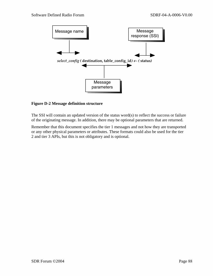
Software Defined Radio Forum SDRF-04-A-0006-V0.00
SDR Forum ©2004 Page 88
select_config ( destination, table_config_id) ← ( status)
Message name Message response (SSI)
Message parameters
Figure D-2 Message definition structure
The SSI will contain an updated version of the status word(s) to reflect the success or failure of the originating message. In addition, there may be optional parameters that are returned.
Remember that this document specifies the tier 1 messages and not how they are transported or any other physical parameters or attributes. These formats could also be used for the tier 2 and tier 3 APIs, but this is not obligatory and is optional.

Software Defined Radio Forum SDRF-04-A-0006-V0.00
SDR Forum ©2004 Page 89
D.1.3 Parameter Formats The following tables specify the format for parameters to be included in messages for commercial hand sets.
A. enable (destination) ← (status)
destination status
Destination ID of the module to be enabled through the API. This is returned to indicate the success or otherwise of the message and the current status of the module. Included in the status word will be the API module ID to confirm that it was sent to the correct location.
A.1 Description This message will enable the module and does not actually start its
functionality. To use the VCR analogy, Enable is the equivalent of powering up the VCR. It does not mean that the VCR should automatically start playing a tape or recording a transmission. It can be used to trigger several actions within the module that uses the API, such as self test, internal resource allocation and initialization, and so on.
A.2 Dependencies This command should be sent only if the module is currently disabled. A.3 Action The module should treat this signal as a request to activate and be ready to
receive and act on further messages. This may include reserving resources in preparation for this.
A.4 Results If the module is currently
disabled and the message sent:
The message should be acted upon. • The status SSI should indicate that
the module is enabled. • The module should be able to receive
further messages but should not process incoming data.
If the module is currently enabled and the message sent:
The message should not be acted upon.
• It should be treated as a programming error.
• The status message should indicate that this is an error.
• The module should continue executing.
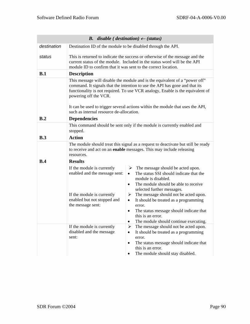
Software Defined Radio Forum SDRF-04-A-0006-V0.00
SDR Forum ©2004 Page 90
B. disable ( destination) ← (status)
destination status
Destination ID of the module to be disabled through the API. This is returned to indicate the success or otherwise of the message and the current status of the module. Included in the status word will be the API module ID to confirm that it was sent to the correct location.
B.1 Description This message will disable the module and is the equivalent of a “power off”
command. It signals that the intention to use the API has gone and that its functionality is not required. To use VCR analogy, Enable is the equivalent of powering off the VCR. It can be used to trigger several actions within the module that uses the API, such as internal resource de-allocation.
B.2 Dependencies This command should be sent only if the module is currently enabled and
stopped. B.3 Action The module should treat this signal as a request to deactivate but still be ready
to receive and act on an enable messages. This may include releasing resources.
B.4 Results If the module is currently
enabled and the message sent: The message should be acted upon.
• The status SSI should indicate that the module is disabled.
• The module should be able to receive selected further messages.
If the module is currently enabled but not stopped and the message sent:
The message should not be acted upon. • It should be treated as a programming
error. • The status message should indicate that
this is an error. • The module should continue executing.
If the module is currently disabled and the message sent:
The message should not be acted upon. • It should be treated as a programming
error. • The status message should indicate that
this is an error. • The module should stay disabled.
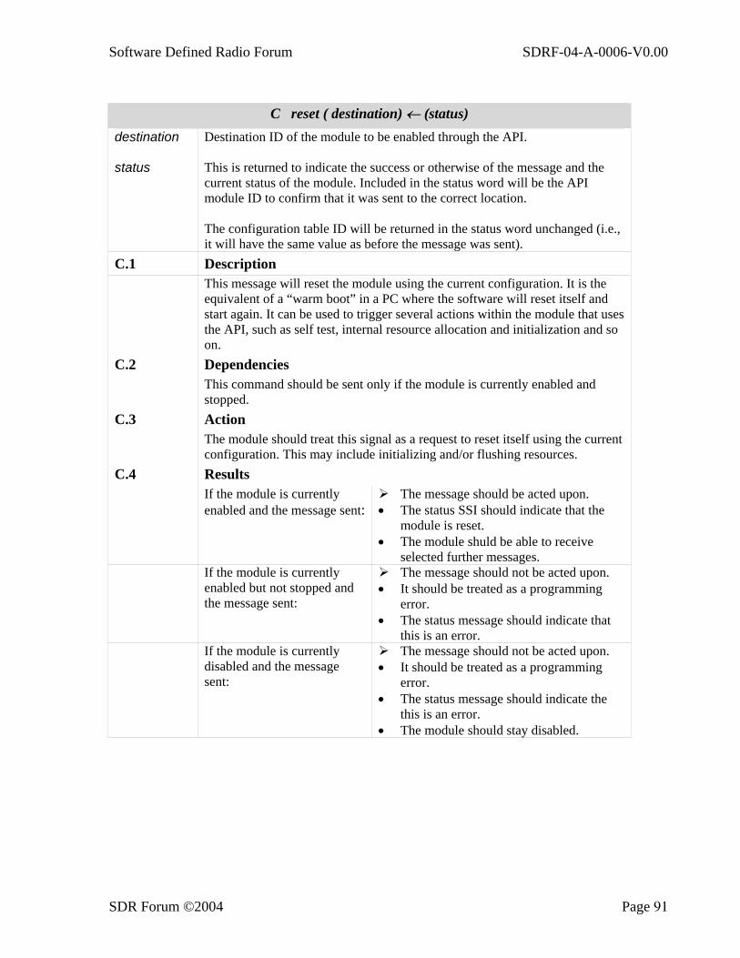
Software Defined Radio Forum SDRF-04-A-0006-V0.00
SDR Forum ©2004 Page 91
C reset ( destination) ← (status)
destination status
Destination ID of the module to be enabled through the API. This is returned to indicate the success or otherwise of the message and the current status of the module. Included in the status word will be the API module ID to confirm that it was sent to the correct location. The configuration table ID will be returned in the status word unchanged (i.e., it will have the same value as before the message was sent).
C.1 Description This message will reset the module using the current configuration. It is the
equivalent of a “warm boot” in a PC where the software will reset itself and start again. It can be used to trigger several actions within the module that uses the API, such as self test, internal resource allocation and initialization and so on.
C.2 Dependencies This command should be sent only if the module is currently enabled and
stopped. C.3 Action The module should treat this signal as a request to reset itself using the current
configuration. This may include initializing and/or flushing resources. C.4 Results If the module is currently
enabled and the message sent: The message should be acted upon.
• The status SSI should indicate that the module is reset.
• The module shuld be able to receive selected further messages.
If the module is currently enabled but not stopped and the message sent:
The message should not be acted upon. • It should be treated as a programming
error. • The status message should indicate that
this is an error. If the module is currently
disabled and the message sent:
The message should not be acted upon. • It should be treated as a programming
error. • The status message should indicate the
this is an error. • The module should stay disabled.

Software Defined Radio Forum SDRF-04-A-0006-V0.00
SDR Forum ©2004 Page 92
D. reset_to_default( destination) ← (status)
destination status
Destination ID of the module to be enabled through the API. This is returned to indicate the success or otherwise of the message and the current status of the module. Included in the status work will be the API module ID to confirm that it was sent to the correct location. The configuration table ID will be set in the status word to 0, thereby indicating that the module has reset to the default configuration.
D.1 Description This message will reset the module using the default configuration. It is the
equivalent of a “cold boot” in a PC where the software will reset itself and start again. It can be used to trigger several actions within the module that uses the API, such as self test, internal resource allocation and initialization, and so on.
D.2 Dependencies This command should be sent only if the module is currently enabled and
stopped. D.3 Action The module should treat this signal as a request to reset itself using the default
configuration. This may include initializing and/or flushing resources. D.4 Results If the module is currently
enabled and the message sent: The message should be acted upon.
• The status SSI should indicate that the module is reset.
• The module should be able to receive selected further messages.
If the module is currently enabled but not stopped and the message sent:
The message should not be acted upon. • It should be treated as a programming
error. • The status message shuld indicate that
this is an error. • The module should continue executing.
If the module is currently disabled and the message sent:
The message should not be acted upon. • It should be treated as a programming
error. • The status message should indicate that
this is an error. • The module should stay disabled.
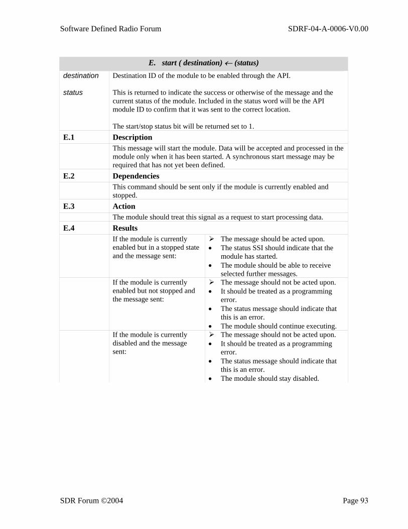
Software Defined Radio Forum SDRF-04-A-0006-V0.00
SDR Forum ©2004 Page 93
E. start ( destination) ← (status)
destination status
Destination ID of the module to be enabled through the API. This is returned to indicate the success or otherwise of the message and the current status of the module. Included in the status word will be the API module ID to confirm that it was sent to the correct location. The start/stop status bit will be returned set to 1.
E.1 Description This message will start the module. Data will be accepted and processed in the
module only when it has been started. A synchronous start message may be required that has not yet been defined.
E.2 Dependencies This command should be sent only if the module is currently enabled and
stopped. E.3 Action The module should treat this signal as a request to start processing data. E.4 Results If the module is currently
enabled but in a stopped state and the message sent:
The message should be acted upon. • The status SSI should indicate that the
module has started. • The module should be able to receive
selected further messages. If the module is currently
enabled but not stopped and the message sent:
The message should not be acted upon. • It should be treated as a programming
error. • The status message should indicate that
this is an error. • The module should continue executing.
If the module is currently disabled and the message sent:
The message should not be acted upon. • It should be treated as a programming
error. • The status message should indicate that
this is an error. • The module should stay disabled.
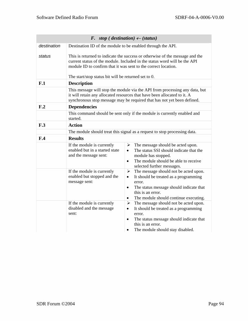
Software Defined Radio Forum SDRF-04-A-0006-V0.00
SDR Forum ©2004 Page 94
F. stop ( destination) ← (status)
destination status
Destination ID of the module to be enabled through the API. This is returned to indicate the success or otherwise of the message and the current status of the module. Included in the status word will be the API module ID to confirm that it was sent to the correct location. The start/stop status bit will be returned set to 0.
F.1 Description This message will stop the module via the API from processing any data, but
it will retain any allocated resources that have been allocated to it. A synchronous stop message may be required that has not yet been defined.
F.2 Dependencies This command should be sent only if the module is currently enabled and
started. F.3 Action The module should treat this signal as a request to stop processing data. F.4 Results If the module is currently
enabled but in a started state and the message sent:
The message should be acted upon. • The status SSI should indicate that the
module has stopped. • The module should be able to receive
selected further messages. If the module is currently
enabled but stopped and the message sent:
The message should not be acted upon. • It should be treated as a programming
error. • The status message should indicate that
this is an error. • The module should continue executing.
If the module is currently disabled and the message sent:
The message should not be acted upon. • It should be treated as a programming
error. • The status message should indicate that
this is an error. • The module should stay disabled.

Software Defined Radio Forum SDRF-04-A-0006-V0.00
SDR Forum ©2004 Page 95
G. set_config ( destination, table_config_id, parameters) ← (status)
destination table_config_ id parameters status
Destination ID of the module to be enabled through the API. This identifies the configuration table that is used to receive the new parameters. The API supports up to n tables with table ID 0 being the default. The total number of tables is defined in the capability exchange information. The default table 0 can either be fixed and not capable of modification or capable of modification. Again, these characteristics are returned in the capability table. These are the parameters that are sent and stored in the configuration table. The actual format will depend on the API definition for each module and will reflect the functionality controlled by the API. This is returned to indicate the success or otherwise of the message and the current status of the module. Included in the status word will be the API module ID to confirm that it was sent to the correct location.
G.1 Description This message allows the module configuration via the API to be changed as
required. The changes do not imply or demand any activation and therefore the process of changing the functionality should be seen as a two stage process: • Set-up the new configuration using set_config and one of the available
configuration tables. • Select this table using the select_config message to activate it.
G.2 Dependencies This command should be sent only if the module is currently enabled. G.3 Action The module should treat this signal as a request to update a configuration
table as selected by table_config_id. G.4 Results If the module is currently
enabled and the message sent:
The message should be acted upon. • The status SSI should indicate that the
message was successful. • The module should be able to receive
selected further messages. If the module is currently
disabled and the message sent:
The message should not be acted upon. • It should be treated as a programming
error. • The status message should indicate that
this is an error. • The module should stay disabled.

Software Defined Radio Forum SDRF-04-A-0006-V0.00
SDR Forum ©2004 Page 96
H. select_config ( destination, table_config_id) ← (status)
destination table_ config_id status
Destination ID of the module to be enabled through the API. This identifies the configuration table to be selected to configure the module. The API supports up to n tables with table ID 0 being the default. The total number of tables is defined in t,he capability exchange information. The default table 0 can either be fixed and not capable of modification or capable of modification. Again, these characteristics are returned in the capability table. This is returned to indicate the success or otherwise of the message and the current status of the module. Included in the status word will be the API module ID to confirm that it was sent to the correct location. The configuration table ID bit will be returned set to the value specified by table_config_id.
H.1 Description This message instructs the module to use the configuration information stored
in the selected configuration table. It is used to signal that this information should now be used. The act of simply writing the information into the table does not imply nor should it be interpreted as requesting an immediate changeover. This select_config message is used to do this as part of a two stage process: • Set up the new configuration using set_config and one of the available
configuration tables. • Select this table using the select_config message to activate it. Note: If the configuration table that is being modified by the set_config command is the current one being used by the module, then any changes made to the table should not change the module’s configuration until the select_config message is sent.
H.2 Dependencies This command should be sent only if the module is currently enabled. H.3 Action
The module should treat this signal as a request to select a configuration table as selected by table_config_id.
H.4 Results If the module is
currently enabled and the message sent:
The message should be acted upon. • The status SSI should indicate that the message was
successful. • The module should be able to receive selected further
messages. If the module is
currently disabled and the message sent:
The message should not be acted upon. • It should be treated as a programming error. • The status message should indicate that this is an
error. • The module should stay disabled.
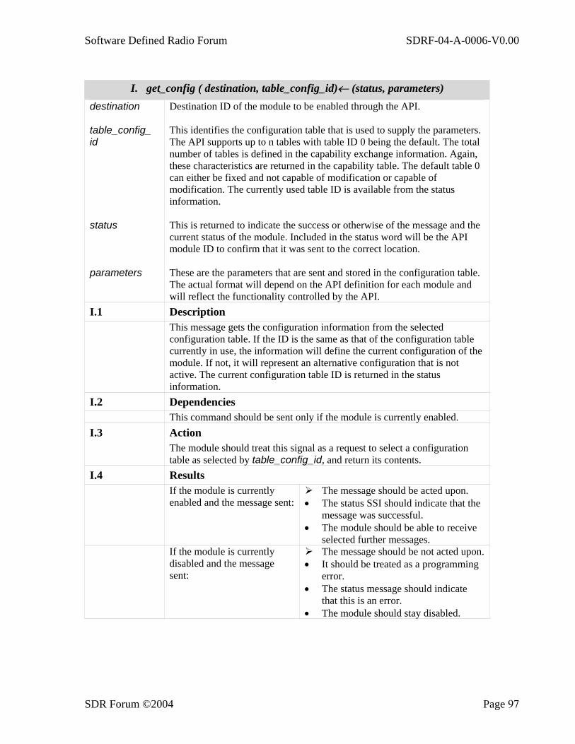
Software Defined Radio Forum SDRF-04-A-0006-V0.00
SDR Forum ©2004 Page 97
I. get_config ( destination, table_config_id)← (status, parameters)
destination table_config_ id status parameters
Destination ID of the module to be enabled through the API. This identifies the configuration table that is used to supply the parameters. The API supports up to n tables with table ID 0 being the default. The total number of tables is defined in the capability exchange information. Again, these characteristics are returned in the capability table. The default table 0 can either be fixed and not capable of modification or capable of modification. The currently used table ID is available from the status information. This is returned to indicate the success or otherwise of the message and the current status of the module. Included in the status word will be the API module ID to confirm that it was sent to the correct location. These are the parameters that are sent and stored in the configuration table. The actual format will depend on the API definition for each module and will reflect the functionality controlled by the API.
I.1 Description This message gets the configuration information from the selected
configuration table. If the ID is the same as that of the configuration table currently in use, the information will define the current configuration of the module. If not, it will represent an alternative configuration that is not active. The current configuration table ID is returned in the status information.
I.2 Dependencies This command should be sent only if the module is currently enabled. I.3 Action The module should treat this signal as a request to select a configuration
table as selected by table_config_id, and return its contents. I.4 Results If the module is currently
enabled and the message sent: The message should be acted upon.
• The status SSI should indicate that the message was successful.
• The module should be able to receive selected further messages.
If the module is currently disabled and the message sent:
The message should be not acted upon. • It should be treated as a programming
error. • The status message should indicate
that this is an error. • The module should stay disabled.
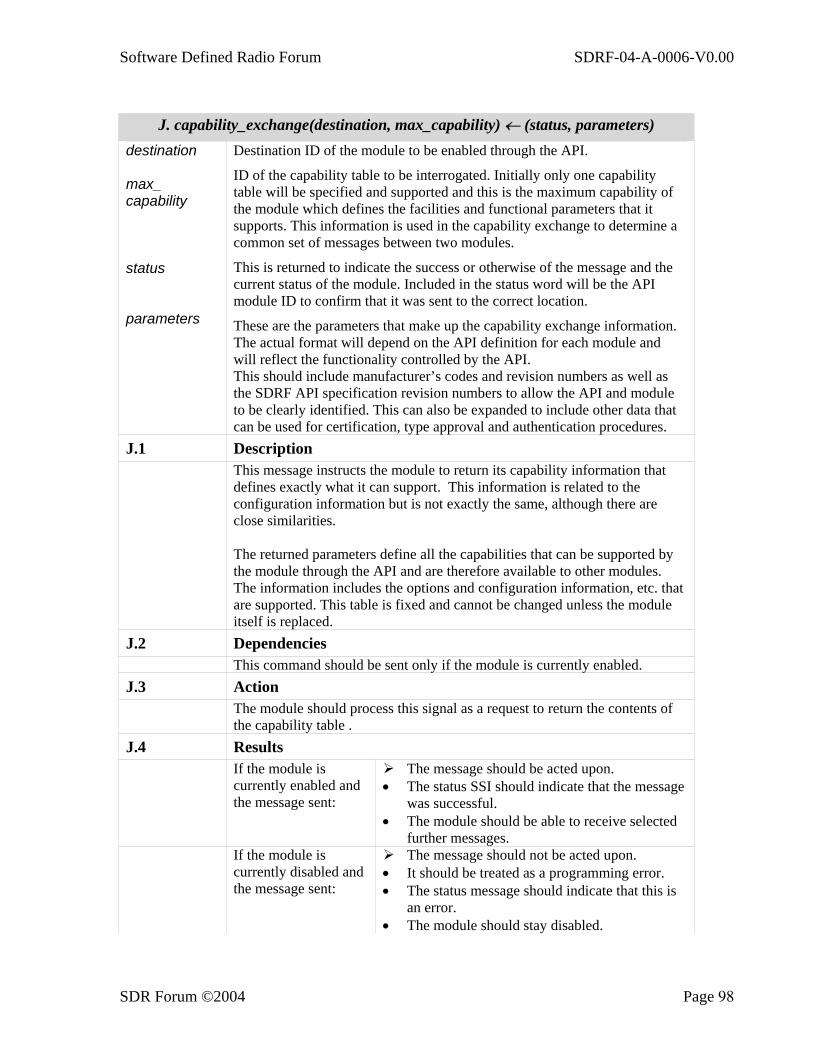
Software Defined Radio Forum SDRF-04-A-0006-V0.00
SDR Forum ©2004 Page 98
J. capability_exchange(destination, max_capability) ← (status, parameters)
destination max_ capability status parameters
Destination ID of the module to be enabled through the API.
ID of the capability table to be interrogated. Initially only one capability table will be specified and supported and this is the maximum capability of the module which defines the facilities and functional parameters that it supports. This information is used in the capability exchange to determine a common set of messages between two modules.
This is returned to indicate the success or otherwise of the message and the current status of the module. Included in the status word will be the API module ID to confirm that it was sent to the correct location.
These are the parameters that make up the capability exchange information. The actual format will depend on the API definition for each module and will reflect the functionality controlled by the API. This should include manufacturer’s codes and revision numbers as well as the SDRF API specification revision numbers to allow the API and module to be clearly identified. This can also be expanded to include other data that can be used for certification, type approval and authentication procedures.
J.1 Description This message instructs the module to return its capability information that
defines exactly what it can support. This information is related to the configuration information but is not exactly the same, although there are close similarities. The returned parameters define all the capabilities that can be supported by the module through the API and are therefore available to other modules. The information includes the options and configuration information, etc. that are supported. This table is fixed and cannot be changed unless the module itself is replaced.
J.2 Dependencies This command should be sent only if the module is currently enabled. J.3 Action The module should process this signal as a request to return the contents of
the capability table . J.4 Results If the module is
currently enabled and the message sent:
The message should be acted upon. • The status SSI should indicate that the message
was successful. • The module should be able to receive selected
further messages. If the module is
currently disabled and the message sent:
The message should not be acted upon. • It should be treated as a programming error. • The status message should indicate that this is
an error. • The module should stay disabled.
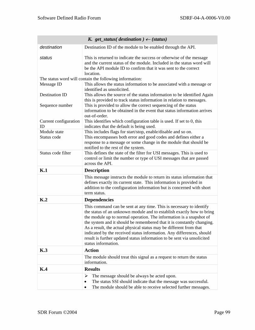
Software Defined Radio Forum SDRF-04-A-0006-V0.00
SDR Forum ©2004 Page 99
K. get_status( destination ) ← (status)
destination status
Destination ID of the module to be enabled through the API. This is returned to indicate the success or otherwise of the message and the current status of the module. Included in the status word will be the API module ID to confirm that it was sent to the correct location.
The status word will contain the following information: Message ID This allows the status information to be associated with a message or
identified as unsolicited. Destination ID This allows the source of the status information to be identified Again
this is provided to track status information in relation to messages. Sequence number This is provided to allow the correct sequencing of the status
information to be obtained in the event that status information arrives out-of-order.
Current configuration ID
This identifies which configuration table is used. If set to 0, this indicates that the default is being used.
Module state This includes flags for start/stop, enable/disable and so on. Status code This encompasses both error and good codes and defines either a
response to a message or some change in the module that should be notified to the rest of the system.
Status code filter This defines the state of the filter for USI messages. This is used to control or limit the number or type of USI messages that are passed across the API.
K.1 Description This message instructs the module to return its status information that
defines exactly its current state. This information is provided in addition to the configuration information but is concerned with short term status.
K.2 Dependencies This command can be sent at any time. This is necessary to identify
the status of an unknown module and to establish exactly how to bring the module up to normal operation. The information is a snapshot of the system and it should be remembered that it is constantly changing. As a result, the actual physical status may be different from that indicated by the received status information. Any differences, should result is further updated status information to be sent via unsolicited status information.
K.3 Action The module should treat this signal as a request to return the status
information. K.4 Results The message should be always be acted upon.
• The status SSI should indicate that the message was successful. • The module should be able to receive selected further messages.

Software Defined Radio Forum SDRF-04-A-0006-V0.00
SDR Forum ©2004 Page 100
L. place_module (destination, info ) ← (status, parameters)
destination info parameters
Destination ID of the module to be replaced, switched or augmented through the API. Information facilitating the replacement, switching or augmentation of the module. This will be specific to the module and the implementation. To be defined.
L.1 Description This message is used to change (replace, modify or augment) the module that
is accessed via the API. It is assumed that the replacement is local and accessible. To get a module from a remote source will be achieved in two stages: the first is to obtain the module and store it locally and the second is to use this command to actually use this new version. The command does not imply or infer that the original module is replaced or whether it is used to replace or switch between software or hardware specific components.
L.2 Dependencies This command should be sent only if the module is currently stopped and
enabled. L.3 Action The module should treat this signal as a request to replace/augment or modify
a module or part of a module that is accessed via the API. After this command, the module should go through the normal enable/start sequence, including capability exchange. This is similar to the process used during module power up.
L.4 Results If the module is currently
enabled and stopped, and the message sent:
The message should be acted upon. • The status SSI should indicate that the
message was successful. • The module should be able to receive
selected further messages. If the module is currently
disabled and the message sent:
The message should not be acted upon. • It should be treated as a programming
error. • The status message should indicate that
this is an error. • The module should stay disabled.
D.2 Examples
D.2.1 The Relationship between Enable/Disable and Start/Stop The relationship between enable, disable, start, and stop is shown in Figure D-3. The enable/disable and start/stop message pairs provide two levels of operation: enabled-but-stopped (EBS) and enabled-and-started (EAS). This is important to allow fine control over the module and to effectively correspond to an on-line and off line state where changes can be made in either state but their effect on the rest of the system is different. In the enabled
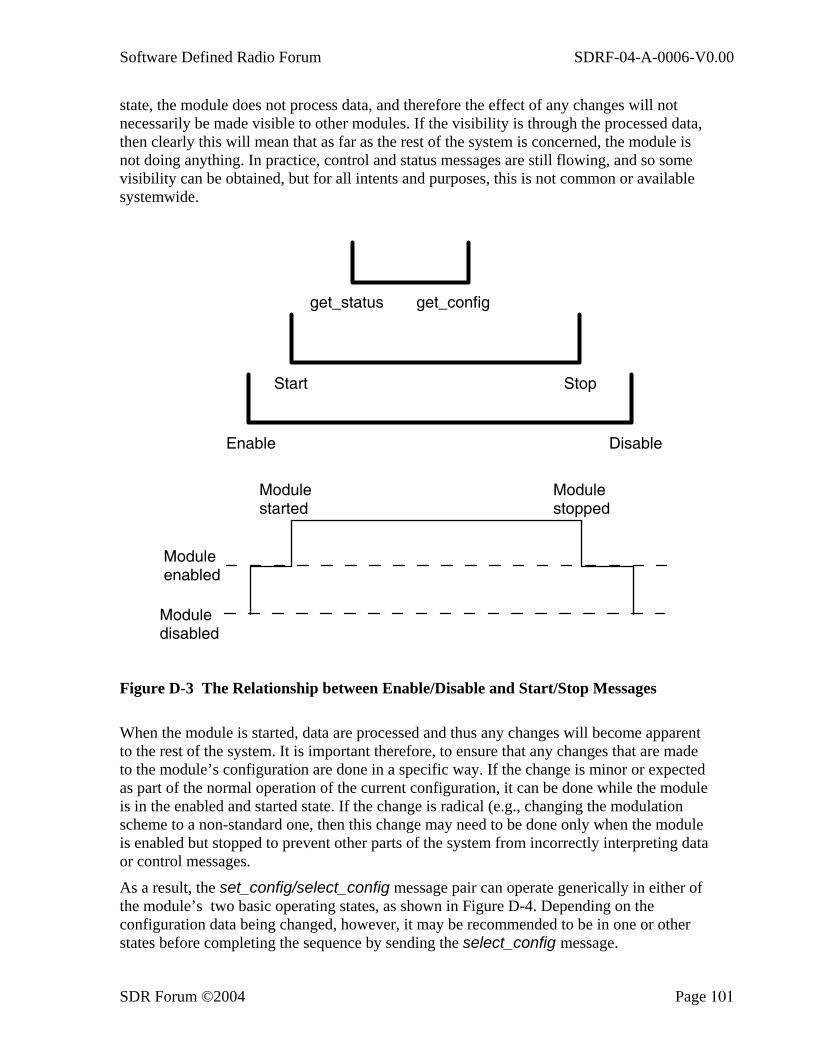
Software Defined Radio Forum SDRF-04-A-0006-V0.00
SDR Forum ©2004 Page 101
state, the module does not process data, and therefore the effect of any changes will not necessarily be made visible to other modules. If the visibility is through the processed data, then clearly this will mean that as far as the rest of the system is concerned, the module is not doing anything. In practice, control and status messages are still flowing, and so some visibility can be obtained, but for all intents and purposes, this is not common or available systemwide.
Enable Disable
Start Stop
get_status get_config
Moduledisabled
Moduleenabled
Modulestarted
Modulestopped
Figure D-3 The Relationship between Enable/Disable and Start/Stop Messages
When the module is started, data are processed and thus any changes will become apparent to the rest of the system. It is important therefore, to ensure that any changes that are made to the module’s configuration are done in a specific way. If the change is minor or expected as part of the normal operation of the current configuration, it can be done while the module is in the enabled and started state. If the change is radical (e.g., changing the modulation scheme to a non-standard one, then this change may need to be done only when the module is enabled but stopped to prevent other parts of the system from incorrectly interpreting data or control messages.
As a result, the set_config/select_config message pair can operate generically in either of the module’s two basic operating states, as shown in Figure D-4. Depending on the configuration data being changed, however, it may be recommended to be in one or other states before completing the sequence by sending the select_config message.

Software Defined Radio Forum SDRF-04-A-0006-V0.00
SDR Forum ©2004 Page 102
Enable Disable
Start Stop
set_config &select_config
can be executed inthese module states
Moduledisabled
Moduleenabled
Modulestarted
Modulestopped
Figure D-4 The Scope of the set_config and select_config Messages
A synchronous start/stop message may be required to simultaneously start/stop multiple modules, but it has not yet been defined.
D.2.2 Module Initialization and Disabling through the API With this example, the process of bringing up a module is described. The example consists of two modules (A and B) that communicate via the API. Module A has to initialize module B, and it already knows what the module is and that it is ready to proceed. If this was not the case, module A could issue a get_status message prior to this process. The option of using the place_module message to download or switch to a new implementation is also not included.
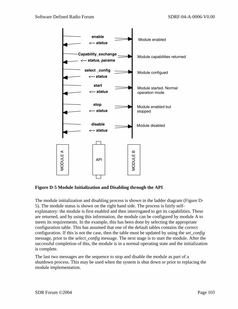
Software Defined Radio Forum SDRF-04-A-0006-V0.00
SDR Forum ©2004 Page 103
enable
<— status
Capability_exchange
<— status, params
select _config
<— status
start
<— status
stop
<— status
Module enabled
Module capabilities returned
Module configued
Module started. Normal operation mode
Module enabled but stopped
Module disableddisable
<— status
API
MO
DU
LE A
MO
DU
LE B
Figure D-5 Module Initialization and Disabling through the API
The module initialization and disabling process is shown in the ladder diagram (Figure D-5). The module status is shown on the right hand side. The process is fairly self-explanatory: the module is first enabled and then interrogated to get its capabilities. These are returned, and by using this information, the module can be configured by module A to meets its requirements. In the example, this has been done by selecting the appropriate configuration table. This has assumed that one of the default tables contains the correct configuration. If this is not the case, then the table must be updated by using the set_config message, prior to the select_config message. The next stage is to start the module. After the successful completion of this, the module is in a normal operating state and the initialization is complete.
The last two messages are the sequence to stop and disable the module as part of a shutdown process. This may be used when the system is shut down or prior to replacing the module implementation.
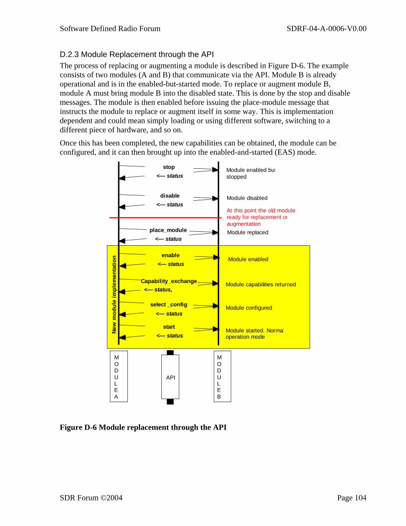
Software Defined Radio Forum SDRF-04-A-0006-V0.00
SDR Forum ©2004 Page 104
D.2.3 Module Replacement through the API The process of replacing or augmenting a module is described in Figure D-6. The example consists of two modules (A and B) that communicate via the API. Module B is already operational and is in the enabled-but-started mode. To replace or augment module B, module A must bring module B into the disabled state. This is done by the stop and disable messages. The module is then enabled before issuing the place-module message that instructs the module to replace or augment itself in some way. This is implementation dependent and could mean simply loading or using different software, switching to a different piece of hardware, and so on.
Once this has been completed, the new capabilities can be obtained, the module can be configured, and it can then brought up into the enabled-and-started (EAS) mode.
place_module<— status
Capability_exchange<— status,
select _config<— status
start<— status
Module replaced
Module capabilities returned
Module configured
Module started. Normaloperation mode
API
MODULEA
MODULEB
enable<— status
Module enabled
stop<— status
Module enabled butstopped
Module disableddisable<— status
New
mod
ule
impl
emen
tatio
n
At this point the old moduleiready for replacement oraugmentation
Figure D-6 Module replacement through the API