SoftTouch Navigation System 250-7614 2011-2013 Ford … · · 2017-06-09SoftTouch Navigation...
16
Rostra Precision Controls, Inc. - 2519 Dana Dr. - Laurinburg, NC 28352 - 800-782-3379 - rostra.com Page 1 SoftTouch Navigation System 250-7614 2011-2013 Ford Edge Installation Instructions General Applicability: Ford - 2011-2013 Explorer, 2011-2013 Taurus, 2011-2013 Flex, 2013 Fusion, 2013 F-150/250/350 Lincoln – 2012-2013 MKZ, MKX, MKS, MKT For video installation instructions, please visit us online at www.rostra.com. INSTALLATION PERFORMED ON FORD EDGE FOR REFERENCE ONLY! Parts Identification Page 1 Vehicle Preparation Page 2 Programming Switch Settings Page 2 Installation Page 3 Parts Identification Item Qty. Description 1 1 Navigation interface module 2 1 Vehicle interface harness 3 1 Stylus 4 1 Navigation interface board 5 1 LCD IN harness and LCD IN harness 6 1 GPS antenna with magnetic base 7 1 GPS speaker 8 1 Speaker and reverse camera input harness 9 1 VHB tape Form #5417, Rev. A, 03-08-13
Transcript of SoftTouch Navigation System 250-7614 2011-2013 Ford … · · 2017-06-09SoftTouch Navigation...

Rostra Precision Controls, Inc. - 2519 Dana Dr. - Laurinburg, NC 28352 - 800-782-3379 - rostra.com Page 1
SoftTouch Navigation System 250-7614 2011-2013 Ford Edge Installation Instructions
General Applicability: Ford - 2011-2013 Explorer, 2011-2013 Taurus, 2011-2013 Flex, 2013 Fusion, 2013 F-150/250/350 Lincoln – 2012-2013 MKZ, MKX, MKS, MKT For video installation instructions, please visit us online at www.rostra.com. INSTALLATION PERFORMED ON FORD EDGE FOR REFERENCE ONLY!
Parts Identification Page 1Vehicle Preparation Page 2Programming Switch Settings Page 2Installation Page 3
Parts Identification
Item Qty. Description 1 1 Navigation interface module 2 1 Vehicle interface harness 3 1 Stylus 4 1 Navigation interface board 5 1 LCD IN harness and LCD IN harness 6 1 GPS antenna with magnetic base 7 1 GPS speaker 8 1 Speaker and reverse camera input harness 9 1 VHB tape
Form #5417, Rev. A, 03-08-13
Rostra Precision Controls, Inc. - 2519 Dana Dr. - Laurinburg, NC 28352 - 800-782-3379 - rostra.com Page 2
STOP – Install At Your Own Risk YOU MUST READ THESE WARNINGS AND NOTICE BEFORE PRODUCT HANDLING AND INSTALLATION! PRODUCT AND VEHICLE APPLICATION WARRANTY DISCLAIMER WARNING! The Navigation Electronic Components are sensitive to Electro-Static Discharge (ESD). DO NOT HANDLE THE NAVIGATION ELECTRONIC COMPONENTS WITHOUT PROPER ESD GROUNDING DURING INSTALLATION. FAILURE TO USE PROPER ESD PROTECTION WHEN HANDLING THE NAVIGATION COMPONENTS WILL VOID THE PRODUCT WARRANTY. WARNING! Installation of this Navigation Electronics product in the vehicle radio head unit must be performed by a professional technician that is experienced with proper work methods, ESD handling requirements, and knowledgeable of specific procedures for radio disassembly, Navigation Electronics installation, and re-assembly of the vehicle Radio Head Unit as well as proper handling requirements of all components involved. FAILURE TO FOLLOW PROPER DISASSEMBLY, INSTALLATION, AND REASSEMBLY PROCEDURES AND PROPER COMPONENT HANDLING REQUIREMENTS MAY RESULT IN IRREVERSIBLE DAMAGE TO THE VEHICLE RADIO HEAD UNIT AND/OR THE NAVIGATION ELECTRONICS AND WILL VOID THE PRODUCT WARRANTY! WARRANTY DISCLAIMER NOTICE! Radio removal, disassembly, installation of Navigation Electronics, and Radio re-assembly/re-installation is the responsibility of the installer, not Rostra Precision Controls, Inc. It is recommended that you contract a professional installer that is experienced with proper work methods involving electronics and knowledgeable of specific procedures for radio disassembly, Navigation Electronics installation, and re-assembly/re-installation of the Radio Head Unit in the vehicle. INSTALLATION DAMAGE TO THE VEHICLE RADIO HEAD UNIT IS NOT THE RESPONSIBILITY OF ROSTRA PRECISION CONTROLS, INC. AND IS EXPRESSLY NOT COVERED UNDER THE PRODUCT WARRANTY.
Rostra Precision Controls, Inc. - 2519 Dana Dr. - Laurinburg, NC 28352 - 800-782-3379 - rostra.com Page 3
WARNING To avoid dangerous distractions that may lead to an accident, the driver should never operate the system while the vehicle is in motion. Before installing this product, the seller should inform the end-user of proper use and compliance with the proper instructions and all state and federal laws. Vehicle Preparation Before beginning your installation, familiarize yourself with the installation instructions and the SoftTouch Navigation system components. To ensure your safety, (A) apply the emergency brake and (B) read this entire manual before beginning.
CAUTION: It is advisable to disconnect the negative battery cable for 3 minutes before beginning installation, to avoid unintended air bag deployment. Note and record any anti-theft radio codes prior to disconnecting.
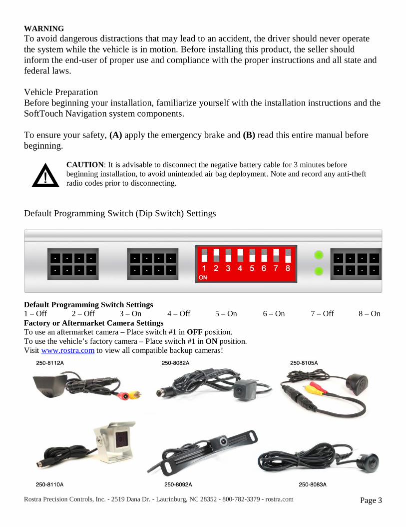
Default Programming Switch (Dip Switch) Settings
Default Programming Switch Settings 1 – Off 2 – Off 3 – On 4 – Off 5 – On 6 – On 7 – Off 8 – On Factory or Aftermarket Camera Settings To use an aftermarket camera – Place switch #1 in OFF position. To use the vehicle’s factory camera – Place switch #1 in ON position. Visit www.rostra.com to view all compatible backup cameras!

Rostra Precision Controls, Inc. - 2519 Dana Dr. - Laurinburg, NC 28352 - 800-782-3379 - rostra.com Page 4
Installation
Using even pressure, gently remove the trim strips running from the center console to the dashboard by lifting them away.
Remove the four screws from both sides of the trim surrounding the vehicle’s shift lever.
Remove the four screws attaching the factory radio trim to the dashboard.
Decouple the clips attaching the radio trim to the shift lever trim.

Rostra Precision Controls, Inc. - 2519 Dana Dr. - Laurinburg, NC 28352 - 800-782-3379 - rostra.com Page 5
Remove the radio trim from the vehicle making sure to unplug the wire harness for the air conditioning controls.
Remove the four screws securing the factory touch screen to the dashboard. Place them somewhere where they will not be lost.
Gently turn the touch screen unit towards the driver’s side of the vehicle to easily access the factory wiring harnesses.
Gently remove these harnesses (Note: the large factory harness includes a locking retainer clip.)

Rostra Precision Controls, Inc. - 2519 Dana Dr. - Laurinburg, NC 28352 - 800-782-3379 - rostra.com Page 6
Gently lift the touch screen unit from the vehicle’s dashboard.
Remove the four screws from the backside of the touch screen unit.
Remove the four screws surrounding the outside of the touch screen unit.
Gently lift open the casing of the touch screen unit to gain access to the ribbon cables on the interior.

Rostra Precision Controls, Inc. - 2519 Dana Dr. - Laurinburg, NC 28352 - 800-782-3379 - rostra.com Page 7
Using a small pry tool, gently release the large ribbon cable tab.
Gently remove the small ribbon cable from the board as well.
Remove the four screws securing the touch screen interface board to the touch screen unit…
…this exposes the interface plug underneath.

Rostra Precision Controls, Inc. - 2519 Dana Dr. - Laurinburg, NC 28352 - 800-782-3379 - rostra.com Page 8
Lift away the backside casing and route the LCD-IN and TP-IN harnesses through the opening.
Reapply the interface board making sure to properly align the factory connector on its backside to the touch screen.
Connect the ribbon cables from the navigation interface board to the touch screen interface board and re-secure the four mounting screws.
Rostra Precision Controls, Inc. - 2519 Dana Dr. - Laurinburg, NC 28352 - 800-782-3379 - rostra.com Page 9
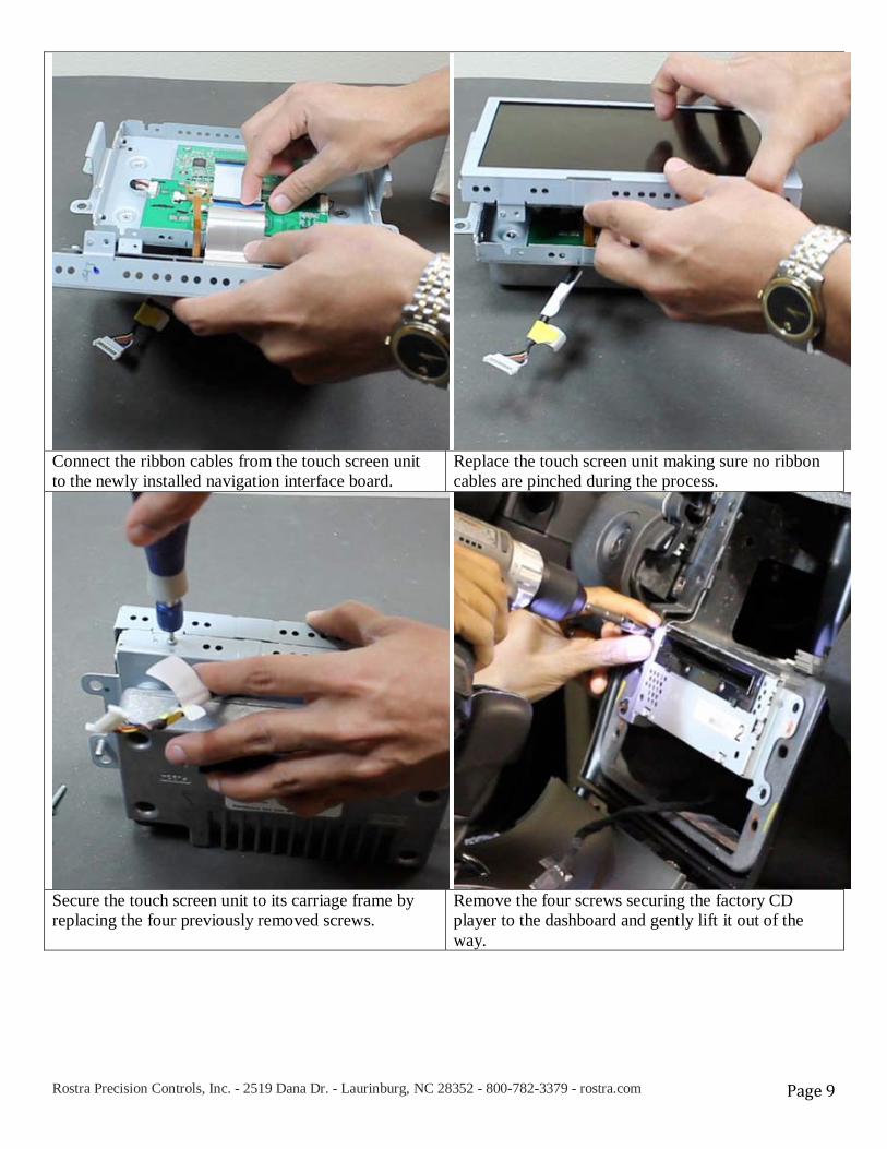
Connect the ribbon cables from the touch screen unit to the newly installed navigation interface board.
Replace the touch screen unit making sure no ribbon cables are pinched during the process.
Secure the touch screen unit to its carriage frame by replacing the four previously removed screws.
Remove the four screws securing the factory CD player to the dashboard and gently lift it out of the way.
Rostra Precision Controls, Inc. - 2519 Dana Dr. - Laurinburg, NC 28352 - 800-782-3379 - rostra.com Page 10
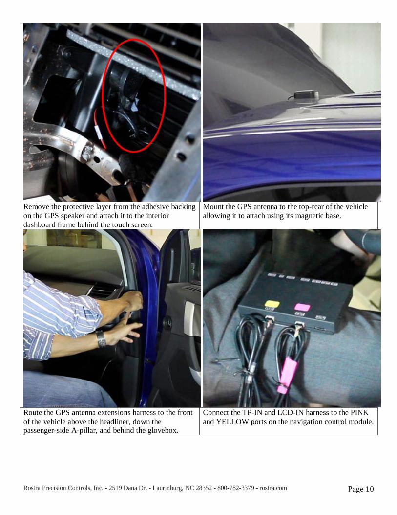
Remove the protective layer from the adhesive backing on the GPS speaker and attach it to the interior dashboard frame behind the touch screen.
Mount the GPS antenna to the top-rear of the vehicle allowing it to attach using its magnetic base.
Route the GPS antenna extensions harness to the front of the vehicle above the headliner, down the passenger-side A-pillar, and behind the glovebox.
Connect the TP-IN and LCD-IN harness to the PINK and YELLOW ports on the navigation control module.
Rostra Precision Controls, Inc. - 2519 Dana Dr. - Laurinburg, NC 28352 - 800-782-3379 - rostra.com Page 11
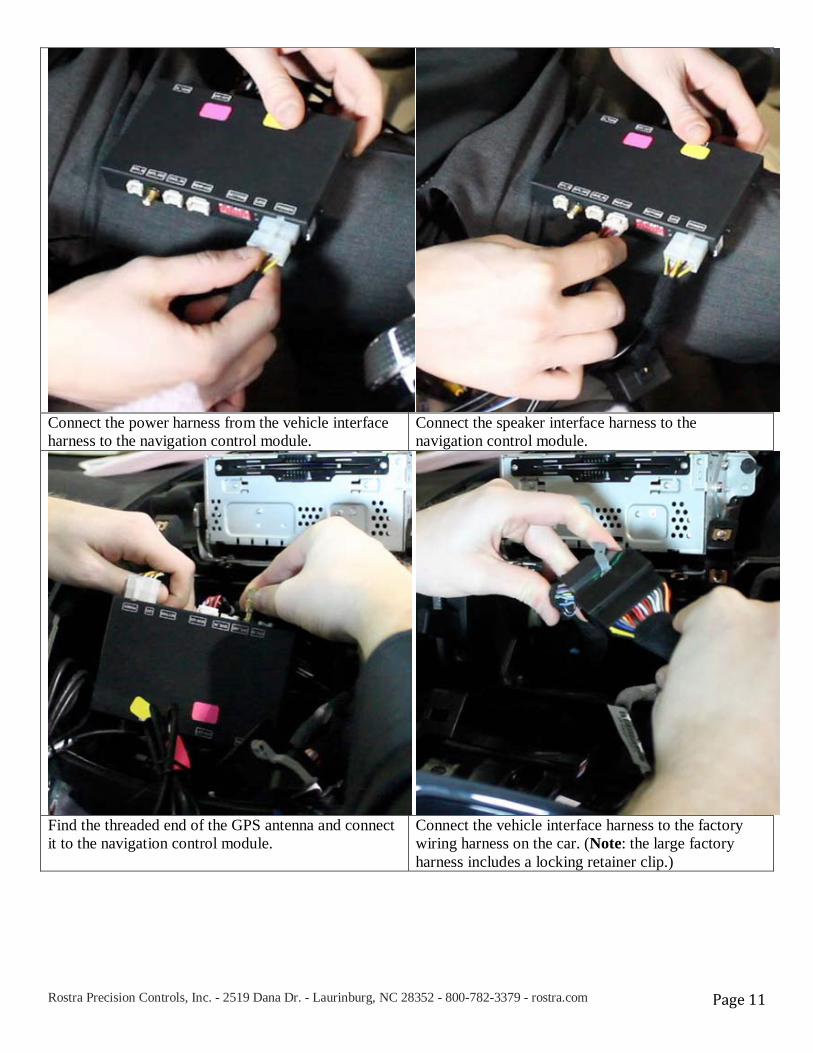
Connect the power harness from the vehicle interface harness to the navigation control module.
Connect the speaker interface harness to the navigation control module.
Find the threaded end of the GPS antenna and connect it to the navigation control module.
Connect the vehicle interface harness to the factory wiring harness on the car. (Note: the large factory harness includes a locking retainer clip.)
Rostra Precision Controls, Inc. - 2519 Dana Dr. - Laurinburg, NC 28352 - 800-782-3379 - rostra.com Page 12
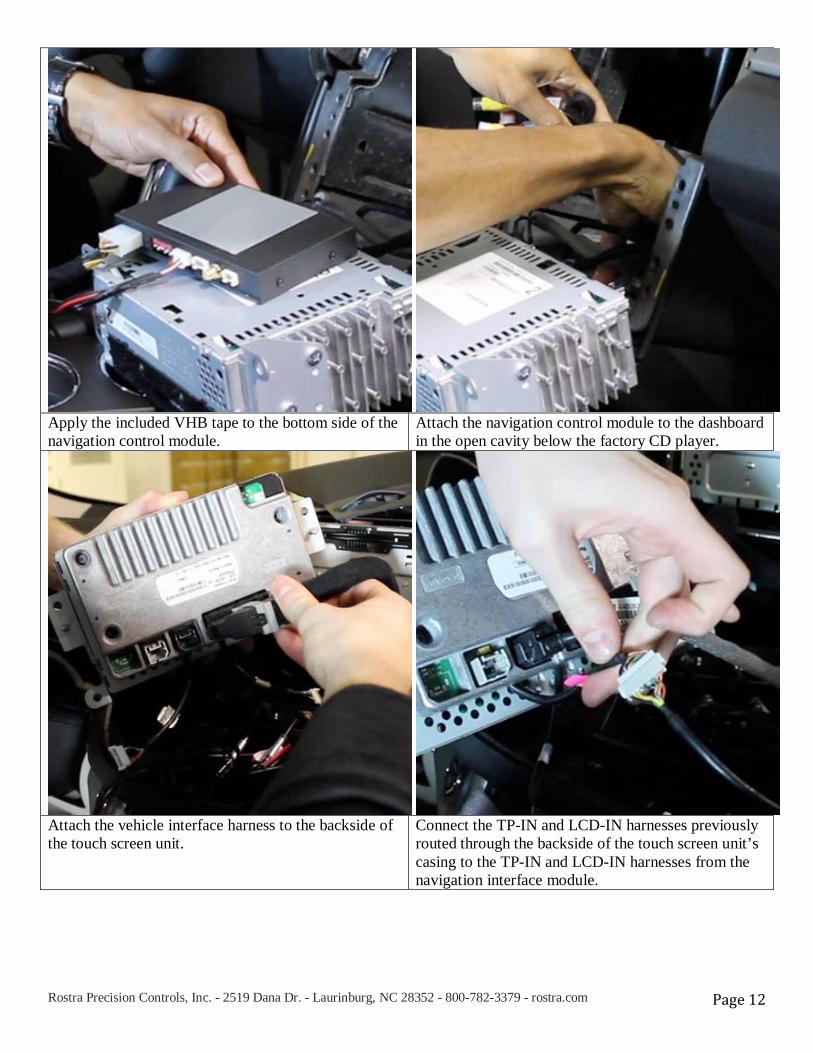
Apply the included VHB tape to the bottom side of the navigation control module.
Attach the navigation control module to the dashboard in the open cavity below the factory CD player.
Attach the vehicle interface harness to the backside of the touch screen unit.
Connect the TP-IN and LCD-IN harnesses previously routed through the backside of the touch screen unit’s casing to the TP-IN and LCD-IN harnesses from the navigation interface module.

Rostra Precision Controls, Inc. - 2519 Dana Dr. - Laurinburg, NC 28352 - 800-782-3379 - rostra.com Page 13
Replace the touch screen unit and factory CD player. Make sure no wires are pinched in the process.
If indoors, start the vehicle and move it outside so that the GPS antenna has a clear view of the sky. Press the mute/call decline button to switch from the factory interface to the iGo Navigation interface.
Reassembly 1. Reinstall all trim pieces taking special care to ensure harnesses and wiring connections are properly secured. 2. Make sure no harnesses are bent or pinched by trim pieces. 3. Reconnect all disconnected bulbs and check for function. Installation Tips • Confirm proper cable extension connector orientation and always verify proper ends are routed in correct direction. • It is a good idea to dry-fit all pieces in this kit before permanently attaching them to ensure proper orientation and
operation before beginning installation for familiarization with components. • Always treat any metal exposed during installation with a rust preventative compound to prevent system failure due to
rust and/or corrosion. • Always seal any holes drilled with the provided sealing putty to prevent water infiltration through unprotected areas. • Confirm integrity of mechanical and electrical connections before moving to next installation sequence. Installation Notes _____________________________________________________________________________ _____________________________________________________________________________ _____________________________________________________________________________

Rostra Precision Controls, Inc. - 2519 Dana Dr. - Laurinburg, NC 28352 - 800-782-3379 - rostra.com Page 14
Installation Notes

Rostra Precision Controls, Inc. - 2519 Dana Dr. - Laurinburg, NC 28352 - 800-782-3379 - rostra.com Page 15
Installation Notes

Rostra Precision Controls, Inc. - 2519 Dana Dr. - Laurinburg, NC 28352 - 800-782-3379 - rostra.com Page 16