Softcopy Photogrammetric Workstations - ASPRSSoftcopy Photogrammetric Workstations Scott B. Miller,...
7
Softcopy Photogrammetric Workstations Scott B. Miller, U. V. Helava, and Kurt Devenecia Helava Associates, Incorporated, A General Dynamics Subsidiary, 10965 Via Frontera, Suite 100, San Diego, CA 92127 ABSTRACT: A summary of softcopy photogrammetric workstations developed by the General Asso- ciates, Incorporated (GOIHAI) team during the past ten years is given. The starts With th.e Stereo Comparator/Compiler (OSCC), and also includes the OMA workstation, the DIgital Imagery Workstation SUIt (DIWS), the Oigital Stereo Photogrammetric Workstation (OSPW), the HAI-750, the Some the latest have been oriented toward the commercial market place. The key aspects dIscussed In thiS paper Include the handling of large amounts of imagery, geometric handling of images, elevation extraction, and e.xtraction..Approaches and solutions to generic technical problems are highlighted even though only top level descnphons are given. INTRODUCTION T HE CONCEPT OF A SOFTCOPY (digital image) photogramme- tric workstation has been around for more than ten years (Sarjakoski, 1981). An example of one such workstation was described by James Case in his paper entitled "The Digital Stereo Comparator/Compiler (oSce)" (Case, 1982). Detailed specifica- tions for that workstation became defined when the Defense Mapping Agency and Rome Air Development Center placed a contract for the development of the osee. The Dsee project was ambitious; the resulting instrument, or "workstation," was designed to meet a comprehensive set of performance requirements. The contract was won by the GD/ HAl team and a dozen of the osee's were delivered in 1985. To our knowledge, the osee was the first operational "softcopy stereoplotter." Several variants have been developed since, in- cluding a new model designed for the Defense Mapping Agency, as well as commercially oriented models. Implementation of softcopy photogrammetric workstations requires finding solutions to several generic technical problems. Interestingly, the photogrammetry portion of it poses no sig- nificant problems. The generic problems are in the image processing area. Most problems arise due to the extremely large size of the photogrammetric images. While storage of such im- ages is no longer a serious problem, fast accessing and process- ing certainly are. Access and data transfer times of commercially available systems are constrained by bus bandwidth, disk ac- cess, and internal memory. Special buses and data structures are necessary for high performance. If the functionality of the best optical- mechanical analytical plotters is to be duplicated, the images must be resampled to achieve many geometric ma- nipulations. Resampling is involved in all geometric manipu- lations of images, such as rectification, rotation, zooming, and even positioning for sub-pixel measurement. Continuous real- time resampling of say 1K by 1K pixel images for a stereo dis- play is not a trivial technical task. Again, special hardware is required for optimum performance. Problems arising from the sizes of photogrammetric images can be greatly reduced if certain trade-offs are permitted. The fundamental trades are in resolution and on-line performance. For example, a standard black-and-white 9- by 9-inch photo- graph digitized to a 50 micro metre pixel size takes "only" 23.3 Megabytes to store. Obviously, potential accuracy and resolu- tion are commensurate, but the end product may still be valu- able and the problems are greatly mitigated. Similarly, system reaction time can be traded for lower equipment complexity and cost. Some functions, such as rotation of the image display, need not be instantaneous. Furthermore, some tasks, e.g., epi- polar rectification (if desired), can be performed as off-line batch processes. Trade-offs in operating concepts can also contribute toward PHOTOGRAMMETRIC ENGINEERING & REMOTE SENSING, Vol. 58, No.1, January 1992, pp. 77-83. solving many technical problems. This includes image tiling, background preprocessing, nearest pixel operations, and "pie- cewise" image roam. Many of the trade-offs described above are not possible when the workstation must meet a given set of specifications. Most of the workstations and associated sys- tems developed by GO/HAI fall into this category. However, the lower-cost workstations (oees, HAI-SOO, and HAI-7S0) are excep- tions; their requirements were self-imposed by the designers. No doubt, various sets of trade-offs will be presented to the market place for "real-life" judgment before softcopy photo- grammetric workstations reach their full maturity. This paper discusses implementation of softcopy worksta- tions designed and built by GO/HAI. Included are: the osee; the Defense Mapping Agency (OMA) Workstation; Digital Imagery Workstation Suite (DIWS); Digital Stereo Photogrammetric Workstation (OSPW); HAI-7S0; and the HAI-SOO. Approaches and solutions to generic technical problems are highlighted even though only top level descriptions are presented in this paper. CUSTOM BUILT WORKSTATIONS This section describes the softcopy workstations custom-de- signed and build by the GO/HAI team with special-purpose hard- ware to meet high performance specifications. DIGITAL STEREO COMPARATOR/COMPILER (DSCC) Functionality. The Digital Stereo Comparator/Compiler (Osee) was de- signed and built to strict specifications and with much func- tionality. These specifications define a paradigm for a "top of the line" photogrammetric workstation. A summary of these specifications is listed below. Orienta tions: • Manual, semi-automatic, and automatic measurement of fiducials, reseaus, and control points to less than 0.3 pixels • Interior, relative, absolute, and simultaneous orientation of mul- tiple sensor types Data Collection: • Automatic elevation measurement (200 points/second) • Manual collection of contours and features • Automatic correlation while delineating features Data Editing: • Manual and semi-automatic positioning • Graphics update while reviewing, roaming, and editing Image manipulation: • At least 256 operator selectable 7- by 7-pixel axially symmetriC individual filters • Tonal look-up tables with reloadable breakpoints • Histogram equalization, brightness, and contrast control • Rotation over 360 degree range, or 90 degree steps 0099-1112/92/5801-77$03.00/0 ©1992 American Society for Photogrammetry and Remote Sensing
Transcript of Softcopy Photogrammetric Workstations - ASPRSSoftcopy Photogrammetric Workstations Scott B. Miller,...
Softcopy Photogrammetric WorkstationsScott B. Miller, U. V. Helava, and Kurt Devenecia HelavaAssociates, Incorporated, A General Dynamics Subsidiary, 10965 Via Frontera, Suite 100, San Diego, CA 92127
ABSTRACT: A summary of softcopy photogrammetric workstations developed by the General O~amic~el.ava Associates, Incorporated (GOIHAI) team during the past ten years is given. The ~u.mmary starts With th.e OlgI~al StereoComparator/Compiler (OSCC), and also includes the OMA workstation, the DIgital Imagery Workstation SUIt (DIWS),the Oigital Stereo Photogrammetric Workstation (OSPW), the HAI-750, a~d the ~-50~. Some ~f the latest effort~ havebeen oriented toward the commercial market place. The key aspects dIscussed In thiS paper Include the handling oflarge amounts of imagery, geometric handling of images, elevation extraction, and featur~ e.xtraction..Approaches andsolutions to generic technical problems are highlighted even though only top level descnphons are given.
INTRODUCTION
T HE CONCEPT OF A SOFTCOPY (digital image) photogrammetric workstation has been around for more than ten years
(Sarjakoski, 1981). An example of one such workstation wasdescribed by James Case in his paper entitled "The Digital StereoComparator/Compiler (oSce)" (Case, 1982). Detailed specifications for that workstation became defined when the DefenseMapping Agency and Rome Air Development Center placed acontract for the development of the osee.
The Dsee project was ambitious; the resulting instrument, or"workstation," was designed to meet a comprehensive set ofperformance requirements. The contract was won by the GD/HAl team and a dozen of the osee's were delivered in 1985. Toour knowledge, the osee was the first operational "softcopystereoplotter." Several variants have been developed since, including a new model designed for the Defense Mapping Agency,as well as commercially oriented models.
Implementation of softcopy photogrammetric workstationsrequires finding solutions to several generic technical problems.Interestingly, the photogrammetry portion of it poses no significant problems. The generic problems are in the imageprocessing area. Most problems arise due to the extremely largesize of the photogrammetric images. While storage of such images is no longer a serious problem, fast accessing and processing certainly are. Access and data transfer times of commerciallyavailable systems are constrained by bus bandwidth, disk access, and internal memory. Special buses and data structuresare necessary for high performance. If the functionality of thebest optical- mechanical analytical plotters is to be duplicated,the images must be resampled to achieve many geometric manipulations. Resampling is involved in all geometric manipulations of images, such as rectification, rotation, zooming, andeven positioning for sub-pixel measurement. Continuous realtime resampling of say 1K by 1K pixel images for a stereo display is not a trivial technical task. Again, special hardware isrequired for optimum performance.
Problems arising from the sizes of photogrammetric imagescan be greatly reduced if certain trade-offs are permitted. Thefundamental trades are in resolution and on-line performance.For example, a standard black-and-white 9- by 9-inch photograph digitized to a 50 micrometre pixel size takes "only" 23.3Megabytes to store. Obviously, potential accuracy and resolution are commensurate, but the end product may still be valuable and the problems are greatly mitigated. Similarly, systemreaction time can be traded for lower equipment complexity andcost. Some functions, such as rotation of the image display,need not be instantaneous. Furthermore, some tasks, e.g., epipolar rectification (if desired), can be performed as off-line batchprocesses.
Trade-offs in operating concepts can also contribute toward
PHOTOGRAMMETRIC ENGINEERING & REMOTE SENSING,Vol. 58, No.1, January 1992, pp. 77-83.
solving many technical problems. This includes image tiling,background preprocessing, nearest pixel operations, and "piecewise" image roam. Many of the trade-offs described aboveare not possible when the workstation must meet a given setof specifications. Most of the workstations and associated systems developed by GO/HAI fall into this category. However, thelower-cost workstations (oees, HAI-SOO, and HAI-7S0) are exceptions; their requirements were self-imposed by the designers.No doubt, various sets of trade-offs will be presented to themarket place for "real-life" judgment before softcopy photogrammetric workstations reach their full maturity.
This paper discusses implementation of softcopy workstations designed and built by GO/HAI. Included are: the osee; theDefense Mapping Agency (OMA) Workstation; Digital ImageryWorkstation Suite (DIWS); Digital Stereo PhotogrammetricWorkstation (OSPW); HAI-7S0; and the HAI-SOO. Approaches andsolutions to generic technical problems are highlighted eventhough only top level descriptions are presented in this paper.
CUSTOM BUILT WORKSTATIONS
This section describes the softcopy workstations custom-designed and build by the GO/HAI team with special-purpose hardware to meet high performance specifications.
DIGITAL STEREO COMPARATOR/COMPILER (DSCC)
Functionality.The Digital Stereo Comparator/Compiler (Osee) was de
signed and built to strict specifications and with much functionality. These specifications define a paradigm for a "top ofthe line" photogrammetric workstation. A summary of thesespecifications is listed below.
Orientations:
• Manual, semi-automatic, and automatic measurement of fiducials,reseaus, and control points to less than 0.3 pixels
• Interior, relative, absolute, and simultaneous orientation of multiple sensor types
Data Collection:
• Automatic elevation measurement (200 points/second)• Manual collection of contours and features• Automatic correlation while delineating features
Data Editing:
• Manual and semi-automatic positioning• Graphics update while reviewing, roaming, and editing
Image manipulation:
• At least 256 operator selectable 7- by 7-pixel axially symmetriCindividual filters
• Tonal look-up tables with reloadable breakpoints• Histogram equalization, brightness, and contrast control• Rotation over 360 degree range, or 90 degree steps
0099-1112/92/5801-77$03.00/0©1992 American Society for Photogrammetry
and Remote Sensing
78 PHOTOGRAMMETRIC ENGINEERING & REMOTE SENSING, 1992
• Zoom from 5:1 to 1:40• Image roaming over 200 pixels per second• Stereo 512 by 512 display• Overview 1024 by 1024 color display
Graphics Superimposition:• Points and lines superimposed in stereo while image roams• Graphics anti-aliased to 1I8-pixel placement• Cursor positioning to 1132 pixel• Overview image and graphics support
Image Capacity:
• 1000 Mega pixelsPhotogrammetric functionality of softcopy workstations, such
as the DSCC, is of great interest to photogrammetrists. Due tothe focus of this paper on implementation, only a cursory description is included. In short, capabilities of the DSCC workstation exceed those of most previous photogrammetric instruments,as evidenced by the specifications listed above. In addition toperforming tasks of the modem analytical plotters, the DSCChas powerful automatic image correlation capabilities. Thesecapabilities include techniques particularly suited for correlationof fiducial and reseau marks, point-by-point correlation, andgeneration of Digital Terrain Models by Hierarchical RelaxationCorrelation (Helava, 1987). The OSCC is capable of handling avariety of geodetic projections and employs an extremely flexible method for representation of image geometries in real-timecomputations.
Because softcopy systems allow one to view images of unusual geometries due to their warping capabilities, the ability totriangulate a variety of image types including frame, panoramic,and SPOT imagery is realized in the osee. The osee can alsotriangulate and view many combinations of sensor types together.
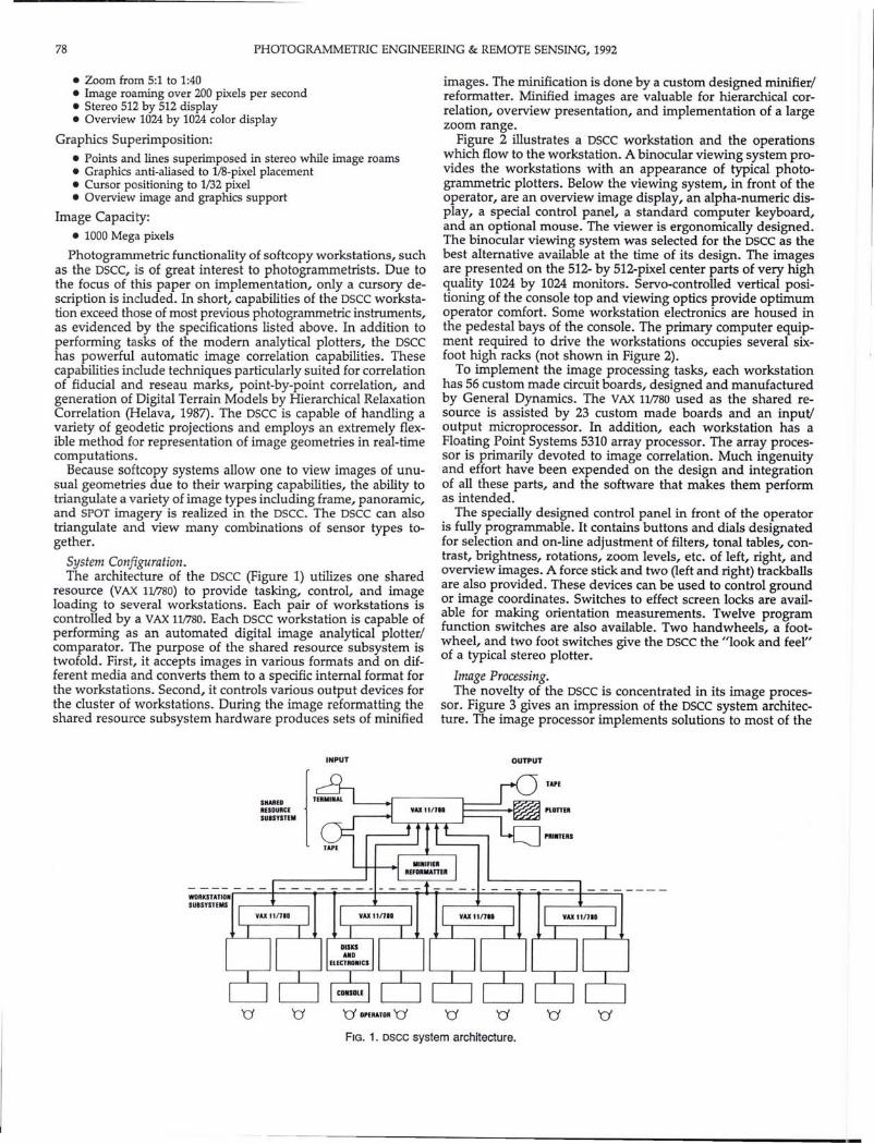
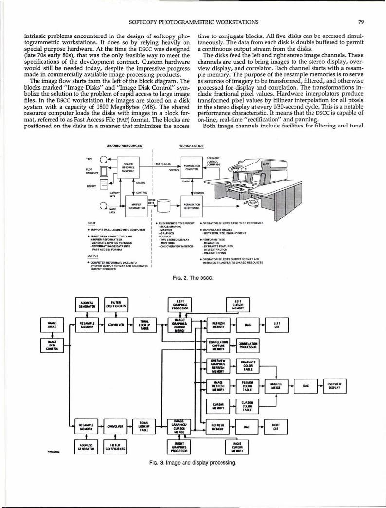
System Configuration.The architecture of the DSCC (Figure 1) utilizes one shared
resource (VAX 11/780) to provide tasking, control, and imageloading to several workstations. Each pair of workstations iscontrolled by a VAX 11/780. Each DSCC workstation is capable ofperforming as an automated digital image analytical plotter/comparator. The purpose of the shared resource subsystem istwofold. First, it accepts images in various formats and on different media and converts them to a specific internal format forthe workstations. Second, it controls various output devices forthe cluster of workstations. During the image reformatting theshared resource subsystem hardware produces sets of minified
INPUT
SHMEDRESOURCESUBSYSTUI
images. The minification is done by a custom designed minifier/reformatter. Minified images are valuable for hierarchical correlation, overview presentation, and implementation of a largezoom range.
Figure 2 illustrates a DSCC workstation and the operationswhich flow to the workstation. A binocular viewing system provides the workstations with an appearance of typical photogrammetric plotters. Below the viewing system, in front of theoperator, are an overview image display, an alpha-numeric display, a special control panel, a standard computer keyboard,and an optional mouse. The viewer is ergonomically designed.The binocular viewing system was selected for the DSCC as thebest alternative available at the time of its design. The imagesare presented on the 512- by 512-pixel center parts of very highquality 1024 by 1024 monitors. Servo-controlled vertical positioning of the console top and viewing optics provide optimumoperator comfort. Some workstation electronics are housed inthe pedestal bays of the console. The primary computer equipment required to drive the workstations occupies several sixfoot high racks (not shown in Figure 2).
To implement the image processing tasks, each workstationhas 56 custom made circuit boards, designed and manufacturedby General DynamiCS. The VAX 11/780 used as the shared resource is assisted by 23 custom made boards and an input!output microprocessor. In addition, each workstation has aFloating Point Systems 5310 array processor. The array processor is primarily devoted to image correlation. Much ingenuityand effort have been expended on the design and integrationof all these parts, and the software that makes them performas intended.
The specially designed control panel in front of the operatoris fully programmable. It contains buttons and dials designatedfor selection and on-line adjustment of filters, tonal tables, contrast, brightness, rotations, zoom levels, etc. of left, right, andoverview images. A force stick and two (left and right) trackballsare also provided. These devices can be used to control groundor image coordinates. Switches to effect screen locks are available for making orientation measurements. Twelve programfunction switches are also available. Two handwheels, a footwheel, and two foot switches give the osce the "look and feel"of a typical stereo plotter.
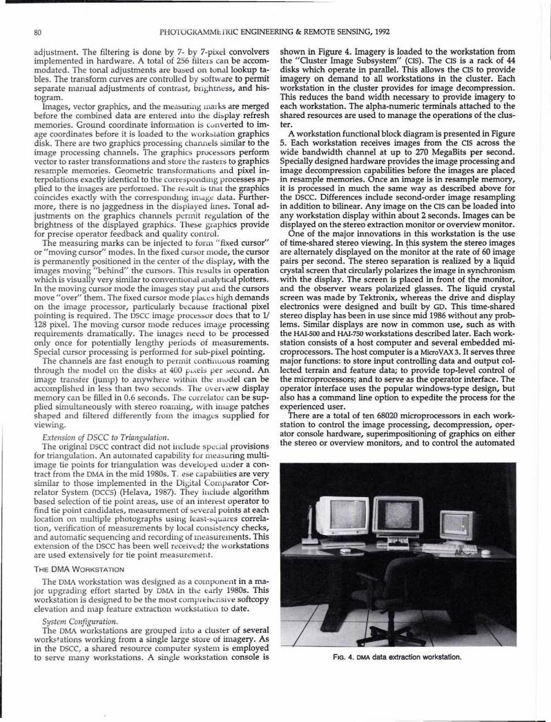
Image Processing.The novelty of the DSCC is concentrated in its image proces
sor. Figure 3 gives an impression of the DSCC system architecture. The image processor implements solutions to most of the
OUTPUT
FIG. 1. Dsee system architecture.
SOFfCOPY PHOTOGRAMMETRIC WORKSTATIONS 79
intrinsic problems encountered in the design of softcopy photogrammetric workstations. It does so by relying heavily onspecial purpose hardware. At the time the osee was designed(late 70s early 80s), that was the only feasible way to meet thespecifications of the development contract. Custom hardwarewould still be needed today, despite the impressive progressmade in commercially available image processing products.
The image flow starts from the left of the block diagram. Theblocks marked "Image Disks" and "Image Disk Control" symbolize the solution to the problem of rapid access to large imagemeso In the osee workstation the images are stored on a disksystem with a capacity of 1800 MegaBytes (MB). The sharedresource computer loads the disks with images in a block format, referred to as Fast Access File (FAF) format. The blocks arepositioned on the disks in a manner that minimizes the access
time to conjugate blocks. All five disks can be accessed simultaneously. The data from each disk is double buffered to permita continuous output stream from the disks.
The disks feed the left and right stereo image channels. Thesechannels are used to bring images to the stereo display, overview display, and correiator. Each channel starts with a resampIe memory. The purpose of the resample memories is to serveas sources of imagery to be transformed, filtered, and otherwiseprocessed for display and correlation. The transformations include fractional pixel values. Hardware interpolators producetransformed pixel values by bilinear interpolation for all pixelsin the stereo display at every 1/30-second cycle. This is a notableperformance characteristic. It means that the osee is capable ofon-line, real-time "rectification" and panning.
Both image channels include facilities for mtering and tonal
SHARED RESOURCES WORKSTATION
TAPE
PlOTHARDCOPY
REPORT
QIMAGEDATA
STATUS
CONTROl
IIII TASK RESULTS
CONTROL
WORKSTATIONCOMPUTER
STATUS
~~~~~ 1--------.
INPUT
• SUPPORT DATA LOADED INTO COMPUTER
• IMAGE DATA LOADED THROUGHMINIFIER REFORMAnER. GENERATE MINIFIED VERSIONS. REFORMAT IMAGE DATA INTO
FAST ACCESS FORMAT
OUTPUT
• COMPUTER REFORMATS DATA INTOPROPER OUTPUT FORMAT AND GENERATESOUTPUT REQUIRED
• ElECTRONICS TO SUPPORT-IMAGE SHAPING. MAO/ROT-GRAPHICS-CURSOR- TWO STEREO DISPLAY
MONITORS- ONE OVERVIEW MONITOR
• OPERATOR SELECTS TASK TO BE PERFORMED
• MANIPULATES IMAGES- AOTATlON. Size, ENHANCEMENT
• PERFORMS TASK· MEASURES• EXTRACTS FEATURES• DTM EXTRACTION- ON-UNE EDITING
• OPERATOR SELECTS OUTPUT FORMAT ANDINITIATES TRANSFER TO SHARED RESOURCES
FIG. 2. The osee.
FIG. 3. Image and display processing.
80 PHOTOGRAMMbfRIC ENGINEERING & REMOTE SENSING, 1992
adjustment. The filtering is done by 7- by 7-pixel convolversimplemented in hardware. A total of 256 filters can be accommodated. The tonal adjustments are based on tonal lookup tables. The transform curves are controlled by software to permitseparate manual adjustments of contrast, bnghtness, and histogram.
Images, vector graphics, and the measuring marks are mergedbefore the combined data are entered into the display refreshmemories. Ground coordinate information is cunverted to image coordinates before it is loaded to the work::.tation graphicsdisk. There are two graphics processing channels similar to theimage processing channels. The graphics proce sors performvector to raster transformations and store the rasters to graphicsresample memories. Geometric transformations and pixel interpolations exactly identical to the corresponding processes applied to the images are performed. The re:5ult is that the graphicscoincides exactly with the corresponding image data. Furthermore, there is no jaggedness in the di1>played lInes. Tonal adjustments on the graphics channels permit regulation of thebrightness of the displayed graphics. These graphics providefor precise operator feedback and quality control.
The measuring marks can be injected to form "fixed cursor"or "moving cursor" modes. In the fixed cursor mode, the cursoris permanently positioned in the center of the dbplay, with theimages moving "behind" the cursors. This re::.ults in operationwhich is visually very similar to conventional analytical plotters.In the moving cursor mode the images stay put and the cursorsmove"over" them. The fixed cursor mode places high demandson the image processor, particularly because fractional pixelpointing is required. The OSCC image processor does that to 1/128 pixel. The moving cursor mode reduces image processingrequirements dramatically. The images need to be processedonly once for potentially lengthy periods of measurements.Special cursor processing is performed for sub-pixel pointing.
The channels are fast enough to permit continuous roamingthrough the model on the disks at 400 pi: els per :.ecund. Animage transfer Gump) to anywhere within the mvdel can beaccomplished in less than two seconds. The oven lew displaymemory can be filled in 0.6 seconds. The correIa tor can be supplied simultaneously with stereo roaming, with image patchesshaped and filtered differently from the images supplied forviewing.
Extension of Dsee to Triangulation.The original OSCC contract did not include spcL'al provisions,
for triangulation. An automated capability for measuring multiimage tie points for triangulation was developed under a contract from the OMA in the mid 1980s. T..ese capabilIties are verysimilar to those implemented in the Digital Comparator Correlator System (OCCS) (Helava, 1987). They include algorithmbased selection of tie point areas, use of an interest operator tofind tie point candidates, measurement of several points at eachlocation on multiple photographs using least-squares correlation, verification of measurements by local consistency checks,and automatic sequencing and recording of measurements. Thisextension of the oscc has been well received: the workstationsare used extensively for tie point measurement.
THE DMA WORKSTATION
The OMA workstation was designed as a component in a major upgrading effort started by OMA in the early 1980s. Thisworkstation is designed to be the most comprehensive softcopyelevation and map feature extraction workstation to date.
System Configuration.The OMA workstations are grouped into a cluster of several
workstations working from a single large store of imagery. Asin the oscc, a shared resource computer system is employedto serve many workstations. A single workstation console is
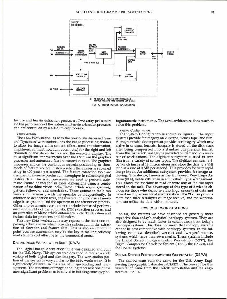
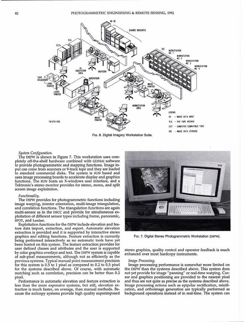
shown in Figure 4. Imagery is loaded to the workstation fromthe "Cluster Image Subsystem" (CIS). The CIS is a rack of 44disks which operate in parallel. This allows the CIS to provideimagery on demand to all workstations in the cluster. Eachworkstation in the cluster provides for image decompression.This reduces the band width necessary to provide imagery toeach workstation. The alpha-numeric terminals attached to theshared resources are used to manage the operations of the cluster.
A workstation functional block diagram is presented in Figure5. Each workstation receives images from the CIS across thewide bandwidth channel at up to 270 MegaBits per second.Specially designed hardware provides the image processing andimage decompression capabilities before the images are placedin resample memories. Once an image is in resample memory,it is processed in much the same way as described above forthe OSCC. Differences include second-order image resamplingin addition to bilinear. Any image on the CIS can be loaded intoany workstation display within about 2 seconds. Images can bedisplayed on the stereo extraction monitor or overview monitor.
One of the major innovations in this workstation is the useof time-shared stereo viewing. In this system the stereo imagesare alternately displayed on the monitor at the rate of 60 imagepairs per second. The stereo separation is realized by a liquidcrystal screen that circularly polarizes the image in synchronismwith the display. The screen is placed in front of the monitor,and the observer wears polarized glasses. The liquid crystalscreen was made by Tektronix, whereas the drive and displayelectronics were designed and built by GO. This time-sharedstereo display has been in use since mid 1986 without any problems. Similar displays are now in common use, such as withthe HAl-SOD and HAl-7S0 workstations described later. Each workstation consists of a host computer and several embedded microprocessors. The host computer is a MicroVAX 3. It serves threemajor functions: to store input controlling data and output collected terrain and feature data; to provide top-level control ofthe microprocessors; and to serve as the operator interface. Theoperator interface uses the popular windows-type design, butalso has a command line option to expedite the process for theexperienced user.
There are a total of ten 68020 microprocessors in each workstation to control the image processing, decompression, operator console hardware, superimpositioning of graphics on eitherthe stereo or overview monitors, and to control the automated
FIG. 4. DMA data extraction workstation.
SOFfCOPY PHOTOGRAMMETRIC WORKSTATIONS 81
IIIGE/ORGCICL CONTROl
CIlI. ..AGE/ORG DATI
III______________________________________________________ ___J
• ~~I:~t~R~E:SO: :::ETI:ofT::~~~~ WORIGE
AC POWER
IIlDL _---+-~
FIG. 5. Multifunction workstation.
feature and terrain extraction processes. Two array processorsaid the perfonnance of the feature and terrain extraction processesand are controlled by a 68020 microprocessor.
Functionality.The OMA Workstation, as with the previously discussed Gen
eral Dynamics' workstations, has the image processing abilitiesto allow for image enhancement (filter, tonal transformation,brightness, contrast, rotation, zoom, etc.) for the right and leftchannels of the stereo display and the overview display. Themost significant improvements over the osee are the graphicsprocessor and automated feature extraction tools. The graphicsprocessor allows the continuous superimpositioning of thousands of feature vectors in stereo when the images are roamedat up to 400 pixels per second. The feature extraction tools aredesigned to increase production throughput in collecting digitalfeature data. The array processors are used to perform automatic feature delineation in three dimensions using a combination of machine vision tools. These include region growing,pattern followers, and correlation. These automatic tools canwork simultaneously with the operator or independently. Inaddition to delineation tools, the workstation provides a knowledge-base system to aid the operator in the attribution process.Other improvements over the osee include increased performance and quality of the automatic OlM extraction process, andan extraction validator which automatically checks elevation andfeature data for problems and blunders.
This new OMA workstations may represent the most encompassing effort known which provides automation in the extraction of elevation and feature data. This is also an importantpoint because automation may be the key to making softcopyworkstations cost effective in the commercial arena.
DIGITAL IMAGE WORKSTATION SUITE (DIWS)
The Digital Image Workstation Suite was designed and builtfor the U.S. Navy. This system was designed to receive a widevariety of both digital and film imagery. The workstation portion of the system is very similar to the OMA workstation. It issignificantly different in the area of image loading and management. The functions of image handling represent one of themost significant problems to be solved in building softcopy pho-
togrammetric instruments. The OIWS architecture does much tosolve this problem.
System Configuration.The System Configuration is shown in Figure 6. The input
systems provide for imagery on VHS tape, 9-track tape, and film.A programmable decompressor provides for imagery which mayarrive in unusual formats. Imagery is stored on the disk stackafter being compressed into a standard compression fonnat.From the disk stack, imagery is provided on demand to a number of workstations. The digitizer subsystem is used to scanfilm from a variety of sensor types. The digitizer can scan a 9by 9-inch image at 12 micrometeres and store the data to a VHStape at a rate of 2 MB per second. This provides for very rapidimage input. An additional subsystem provides for image archiving. This device, known as the Honeywell Very Large Archive (VLA), holds VHS tapes in a "jukebox" type arrangement.This allows the machine to read or write any of the 600 tapesstored in the rack. The advantage of this type of device is obvious for those who desire to store large amounts of data andhave it readily accessible at a workstation. The VLA can providemore than three terrabytes of image archive, and the workstation can utilize the data within minutes.
LOW COST WORKSTATIONS
So far, the systems we have described are generally moreexpensive than today's analytical hardcopy systems. They arealso designed to be much faster in certain areas than today'shardcopy systems. This does not mean that softcopy systemscannot be cost competitive with hardcopy systems. In the following sections we describe lower cost, and lower perfonnance,systems which have their own merits. These systems includethe Digital Stereo Photogrammetric Workstation (OSPW), theDigital Comparator CorreIator System (oees), the HAl-SOD, andthe HAl-7S0 systems.
DIGITAL STEREO PHOTOGRAMMETRIC WORKSTATION (DSPW)
The GO/HAl team built the ospw for the U.S. Anny Engineering Topographic Laboratory (USAETL). The concept for thisworkstation came from the HAl-SOD workstation and the engineers at USAETL.
82 PHOTOGRAMMETRIC ENGINEERING & REMOTE SENSING, 1992
WORKSTATIONAREA
LEGEND:
101 - IMAGE DATA INPUT
¥LA - VHS TAPE ARCHIVE
CCT - COMPUTER COMPATIBLE TAPE
IDS - IMAGE DATA STORAGE
FIG. 6. Digital Imagery Workstation Suite.
System Configuration.The DSPW is shown in Figure 7. This workstation uses com
pletely off-the-shelf hardware combined with GD/HAI softwareto provide photogrammetric and mapping functions. Image input can come from scanners or 9-track tape and they are loadedto standard commercial disks. The system is SUN based anduses image processing boards to accelerate display and graphicsfunctions. The SUN hosts an X-windows user interface, and aTektronix's stereo monitor provides for stereo, mono, and splitscreen image exploitation.
Functionality.The DSPW provides for photogrammetric functions including
image warping, interior orientation, multi-image triangulation,and correlation functions. The triangulation functions are againmulti-sensor as in the DSCC and provide for simultaneous exploitation of different sensor types including frame, panoramic,SPOT, and Landsat.
Exploitation functions for the DSPW include elevation and feature data import, extraction, and export. Automatic elevationextraction is provided and it is supported by interactive stereographics and editing functions. Feature extraction is currentlybeing performed interactively as no automatic tools have yetbeen hosted on this system. The feature extraction provides foruser defined classes and attributes and the user is supportedby color graphics overlays and text. The DSPW system is capableof sub-pixel measurements, although not as efficiently as theprevious systems. Typical manual point measurement precisionfor this system is 0.5 to 1 pixel as compared to 0.2 to 0.5 pixelfor the systems described above. Of course, with automaticmatching such as correlation, precision can be better than 0.2pixel.
Performance in automatic elevation and feature extraction isless than the more expensive systems, but still, elevation extraction is much faster, on average, than manual methods. Because the softcopy systems provide high quality superimposed
FIG. 7. Digital Stereo Photogrammetric Workstation (DSPW).
stereo graphics, quality control and operator feedback is muchenhanced over most hardcopy instruments.
Image Processing.Image processing performance is somewhat more limited on
the DSPW than the systems described above. This system doesnot yet provide for image "panning" or real-time warping. Cursor and graphics positioning are provided to the nearest pixeland thus are not quite as precise as the systems described above.Image processing actions such as epipolar rectification, rninification, and orthoimage generation are typically performed asbackground operations instead of in real-time. The system can
SOFfCOPY PHOTOGRAMMETRIC WORKSTATIONS 83
provide filter, zoom, rotation, and radiometric manipulationson mono or stereo imagery. The imagery is tiled much like theFAF structure described above. This provides for faster accessto any portion of very large images. The DSPW can provideexploitation for large images such as 9- by 9-inch images scannedat 12 rnicrometres. This allows the system to nearly match theprecision of the best analytical plotters provided that good quality scanning is performed. Of course, this type of system ismore accurate than an analytical plotter for processing digitaldata such as SPOT.
THE HAI-500 AND HAI-750
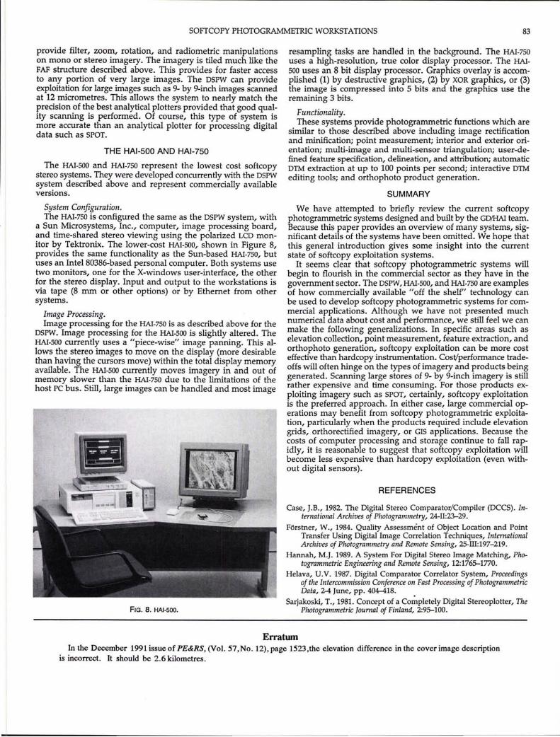
The HAl-SOD and HAl-7S0 represent the lowest cost softcopystereo systems. They were developed concurrently with the DSPWsystem described above and represent commercially availableversions.
System Configuration.The HAI-7S0 is configured the same as the DSPW system, with
a Sun Microsystems, Inc., computer, image processing board,and time-shared stereo viewing using the polarized LCD monitor by Tektronix. The lower-cost HAl-SOD, shown in Figure 8,provides the same functionality as the Sun-based HAl-7S0, butuses an Intel80386-based personal computer. Both systems usetwo monitors, one for the X-windows user-interface, the otherfor the stereo display. Input and output to the workstations isvia tape (8 mm or other options) or by Ethernet from othersystems.
Image Processing.Image processing for the HAl-7S0 is as described above for the
DSPW. Image processing for the HAl-SOD is slightly altered. TheHAl-SOD currently uses a "piece-wise" image panning. This allows the stereo images to move on the display (more desirablethan having the cursors move) within the total display memoryavailable. The HAl-SOD currently moves imagery in and out ofmemory slower than the HAl-7S0 due to the limitations of thehost PC bus. Still, large images can be handled and most image
FIG. 8. HAI-SOO.
resampling tasks are handled in the background. The HAl-7S0uses a high-resolution, true color display processor. The HAlSOD uses an 8 bit display processor. Graphics overlay is accomplished (1) by destructive graphics, (2) by XOR graphics, or (3)the image is compressed into 5 bits and the graphics use theremaining 3 bits.
Functionality.These systems provide photogrammetric functions which are
similar to those described above including image rectificationand rninification; point measurement; interior and exterior orientation; multi-image and multi-sensor triangulation; user-defined feature specification, delineation, and attribution; automaticDlM extraction at up to 100 points per second; interactive DlMediting tools; and orthophoto product generation.
SUMMARY
We have attempted to briefly review the current softcopyphotogrammetric systems designed and built by the GD/HAI team.Because this paper provides an overview of many systems, significant details of the systems have been omitted. We hope thatthis general introduction gives some insight into the currentstate of softcopy exploitation systems.
It seems clear that softcopy photogrammetric systems willbegin to flourish in the commercial sector as they have in thegovernment sector. The DSPW, HAl-SOD, and HAl-7S0 are examplesof how commercially available "off the shelf" technology canbe used to develop softcopy photogrammetric systems for commercial applications. Although we have not presented muchnumerical data about cost and performance, we still feel we canmake the following generalizations. In specific areas such aselevation collection, point measurement, feature extraction, andorthophoto generation, softcopy exploitation can be more costeffective than hardcopy instrumentation. Cost/performance tradeoffs will often hinge on the types of imagery and products beinggenerated. Scanning large stores of 9- by 9-inch imagery is stillrather expensive and time consuming. For those products exploiting imagery such as SPOT, certainly, softcopy exploitationis the preferred approach. In either case, large commercial operations may benefit from softcopy photogrammetric exploitation, particularly when the products required include elevationgrids, orthorectified imagery, or GIS applications. Because thecosts of computer processing and storage continue to fall rapidly, it is reasonable to suggest that softcopy exploitation willbecome less expensive than hardcopy exploitation (even without digital sensors).
REFERENCES
Case, J.B., 1982. The Digital Stereo Comparator/Compiler (DCCS). International Archives of Photogrammetry, 24-II:23-29.
Forstner, W., 1984. Quality Assessment of Object Location and PointTransfer Using Digital Image Correlation Techniques, InternationalArchives of Photogrammetry and Remote Sensing, ZS-ill:197-219.
Hannah, M.J. 1989. A System For Digital Stereo Image Matching, Photogrammetric Engineering and Remote Sensing, 12:1765-1770.
Helava, U.V. 1987. Digital Comparator Correlator System, Proceedingsof the Intercommission Conference on Fast Processing of PhotogrammetricData, 2-4 June, pp. 404-418. .
Sarjakoski, T., 1981. Concept of a Completely Digital Stereoplotter, ThePhotogrammetric Journal of Finland, 2:95-100.
ErratwnIn the December 1991 issue of PE&RS, (Vol. 57, No. 12), page 1523,the elevation difference in the cover image description
is incorrect. It should be 2.6 kilometres.