Soft X-ray resonant magnetic scattering studies on Fe/CoO exchange bias system
5
Journal of Magnetism and Magnetic Materials 300 (2006) 206–210 Soft X-ray resonant magnetic scattering studies on Fe/CoO exchange bias system Florin Radu 1 , Alexei Nefedov , Johannes Grabis, Gregor Nowak, Andre Bergmann, Hartmut Zabel Experimentalphysik/Festko¨rperphysik,Ruhr-Universita ¨ t Bochum, D-44780 Bochum, Germany Available online 16 November 2005 Abstract We have used soft X-ray resonant magnetic scattering (XRMS) to search for the presence of an effective ferromagnetic moment belonging to the antiferromagnetic (AF) layer which is in close contact with a ferromagnetic (F) layer. Taking advantage of the element specificity of the XRMS technique, we have measured hysteresis loops of both Fe and CoO layers of a CoO(40 A ˚ )/Fe (150 A ˚ ) exchange bias bilayer. From these measurements we have concluded that the proximity of the F layer induces a magnetic moment in the AF layer. The F moment of the AF layer has two components: one is frozen and does not follow the applied magnetic field and the other one follows in phase the ferromagnetic magnetization of the F layer. The temperature dependence of the F components belonging to the AF layer is shown and discussed. r 2005 Elsevier B.V. All rights reserved. PACS: 75.25+z; 75.60.Jk; 75.70.Cn; 61.10.Kwn Keywords: Exchange bias; X-ray resonant magnetic scattering 1. Introduction Exchange bias refers to a shift of the ferromagnetic (F) hysteresis loop to positive or negative values when a F system is in contact with an antiferromagnetic (AF) system and cooled in an applied magnetic field through the Ne´el temperature of the AF system. The exchange bias phenomenon is associated with the interfacial exchange coupling between ferromagnetic and antiferromagnetic spin structures, resulting in an unidirectional magnetic anisotropy [1,2]. While the unidirectional anisotropy was successfully introduced by Meiklejohn and Bean (M&B), the origin of the enhanced coercive field is yet not well understood. The exchange bias effect is essential for the development of magneto-electronic switching devices (spin- valves) and for random access magnetic storage units. For these applications a predictable, robust, and tunable exchange bias effect is required. Extensive data have been collected on the exchange bias field H EB and the coercivity field H c , for a large number of bilayer systems, which are reviewed in Refs. [3–6]. The details of the EB effect depend crucially on the AF/F combination chosen and on the structure and thickness of the films. However, some characteristic features apply to most systems: (1) H EB and H c increase as the system is cooled in an applied magnetic field below the blocking temperature T B pT N of the AF layer, where T N is the Ne´el temperature of the AF layer; (2) the magnetization reversal can be different for the ascending and descending part of the hysteresis loop [7–10], as was first pointed out in Ref. [11]; (3) thermal relaxation effects of H EB and H c indicate that a stable magnetic state is reached only at very low temperatures [12–14]. Several theoretical models have been developed for describing possible mechanisms of the EB effect, including ARTICLE IN PRESS www.elsevier.com/locate/jmmm 0304-8853/$ - see front matter r 2005 Elsevier B.V. All rights reserved. doi:10.1016/j.jmmm.2005.10.064 Corresponding author. Institut fu¨r Experimentalphysik/Festko¨rper- physik, Ruhr-Universita¨ t Bochum, 44780 Bochum, Germany. Tel.: +49 234 322 3620; fax: +49 234 321 4173. E-mail address: [email protected] (A. Nefedov). URL: http://www.ep4.ruhr-uni-bochum.de. 1 Present address: BESSYGmbH, Albert-Einstein str. 15, D-12489 Berlin, Germany.
-
Upload
florin-radu -
Category
Documents
-
view
212 -
download
0
Transcript of Soft X-ray resonant magnetic scattering studies on Fe/CoO exchange bias system

ARTICLE IN PRESS
0304-8853/$
doi:10.1016
�Correspphysik, Ru
+49 234 32
E-mail a
URL: h1Present
Berlin, Ger
Journal of Magnetism and Magnetic Materials 300 (2006) 206–210
www.elsevier.com/locate/jmmm
Soft X-ray resonant magnetic scattering studies onFe/CoO exchange bias system
Florin Radu1, Alexei Nefedov�, Johannes Grabis, Gregor Nowak,Andre Bergmann, Hartmut Zabel
Experimentalphysik/Festkorperphysik, Ruhr-Universitat Bochum, D-44780 Bochum, Germany
Available online 16 November 2005
Abstract
We have used soft X-ray resonant magnetic scattering (XRMS) to search for the presence of an effective ferromagnetic moment
belonging to the antiferromagnetic (AF) layer which is in close contact with a ferromagnetic (F) layer. Taking advantage of the element
specificity of the XRMS technique, we have measured hysteresis loops of both Fe and CoO layers of a CoO(40 A)/Fe (150 A) exchange
bias bilayer. From these measurements we have concluded that the proximity of the F layer induces a magnetic moment in the AF layer.
The F moment of the AF layer has two components: one is frozen and does not follow the applied magnetic field and the other one
follows in phase the ferromagnetic magnetization of the F layer. The temperature dependence of the F components belonging to the AF
layer is shown and discussed.
r 2005 Elsevier B.V. All rights reserved.
PACS: 75.25+z; 75.60.Jk; 75.70.Cn; 61.10.Kwn
Keywords: Exchange bias; X-ray resonant magnetic scattering
1. Introduction
Exchange bias refers to a shift of the ferromagnetic (F)hysteresis loop to positive or negative values when a Fsystem is in contact with an antiferromagnetic (AF) systemand cooled in an applied magnetic field through the Neeltemperature of the AF system. The exchange biasphenomenon is associated with the interfacial exchangecoupling between ferromagnetic and antiferromagneticspin structures, resulting in an unidirectional magneticanisotropy [1,2]. While the unidirectional anisotropy wassuccessfully introduced by Meiklejohn and Bean (M&B),the origin of the enhanced coercive field is yet not wellunderstood. The exchange bias effect is essential for the
- see front matter r 2005 Elsevier B.V. All rights reserved.
/j.jmmm.2005.10.064
onding author. Institut fur Experimentalphysik/Festkorper-
hr-Universitat Bochum, 44780 Bochum, Germany. Tel.:
2 3620; fax: +49 234 321 4173.
ddress: [email protected] (A. Nefedov).
ttp://www.ep4.ruhr-uni-bochum.de.
address: BESSYGmbH, Albert-Einstein str. 15, D-12489
many.
development of magneto-electronic switching devices (spin-valves) and for random access magnetic storage units. Forthese applications a predictable, robust, and tunableexchange bias effect is required.Extensive data have been collected on the exchange bias
field HEB and the coercivity field Hc, for a large number ofbilayer systems, which are reviewed in Refs. [3–6]. Thedetails of the EB effect depend crucially on the AF/Fcombination chosen and on the structure and thickness ofthe films. However, some characteristic features apply tomost systems: (1) HEB and Hc increase as the system iscooled in an applied magnetic field below the blockingtemperature TBpTN of the AF layer, where TN is the Neeltemperature of the AF layer; (2) the magnetization reversalcan be different for the ascending and descending part ofthe hysteresis loop [7–10], as was first pointed out in Ref.[11]; (3) thermal relaxation effects of HEB and Hc indicatethat a stable magnetic state is reached only at very lowtemperatures [12–14].Several theoretical models have been developed for
describing possible mechanisms of the EB effect, including
ARTICLE IN PRESS
0.0 0.1 0.2 0.3 0.4 0.5 0.6
10-6
10-5
10-4
10-3
10-2
10-1
100
0 50 100 150 200
0
1
2
3
4
dataFit
Ref
lect
ivity
Q [Å-1](a)
SLD
*105 [
Å-1
]
z [Å]
2.4 2.6 2.8 3.0 3.2 3.4
10-3
10-2
10-1
(b) Q [Å-1]
Al2O3(1120)
Nor
mal
ised
Int
ensi
ty
Fe(110)
Fig. 1. (a) Reflectivity curve of the CoO/Fe bilayer structure (open
symbols are the experimental data, the line is a fit using a model presented
in the inset). (b) The radial scan in the direction normal to the sample
surface around the Al2O3ð1 1 2 0Þ and Fe(1 1 0) Bragg peak positions.
F. Radu et al. / Journal of Magnetism and Magnetic Materials 300 (2006) 206–210 207
domain formation in the AF layer with domain wallsperpendicular to the AF/F interface [15], creation ofuncompensated excess AF spins at the interface [16], orthe formation of domain walls in the AF layer parallel tothe interface [17,18]. Another approach is the considerationof diluted antiferromagnets in an exchange field. In thework of Miltenyi et al., Keller et al., and Nowak et al.[19–21] the discussion about compensated versus uncom-pensated interfacial spins is replaced by a discussion of netmagnetic moments within the AF layer. The AF domainswill carry a resulting magnetization which will decreasenon-exponentially with very high relaxation times. Thisinduced magnetization in the AF layer is frozen and withinthe domain state model it is responsible for the hysteresisshift. Ohldag et al. [22] and Kappenberger et al. [23]observed that a small fraction of the AF spins areuncompensated and responsible for the EB shift, aspredicted by M&B model [1,2]. We concentrate on theobservation of rotatable AF spins which contribute to theenhanced coercivity, reported for almost all systemdescribed in the literature. They are essential for under-standing the coercivity enhancement as shown in Ref. [24].There, the coercivity was modelled by an extended M&Bmodel and assuming an interface AF layer with variableanisotropy.
In this paper, hysteresis loops of the induced ferromag-netic components belonging to the AF layer at the AF/Fare described and compared with the magnetization curvesof the ferromagnet itself.
2. Sample growth and hard X-ray characterization
As substrate we used epi-polished single-crystallineð1 1 2 0Þ-oriented sapphire wafer. Before deposition, thesubstrates were ultrasonically cleaned in acetone andethanol and then transferred into a high-vacuum RF-sputtering chamber which provides a base pressure of1� 10�7 mbar. Prior to the deposition the substrate wereannealed at 500 �C for 3 h and etched for 10min with an Arion beam. Then the substrate was cooled down to 200 �C,where the Fe layer has been deposited by RF-sputtering inAr with a partial pressure of 5� 10�3 mbar. Subsequently,the polycrystalline CoO layer has been grown by sputteringof Co atoms in a mixture of Ar (94%) and O2 (6%). Thedeposition rates were 0.48 A/s and 0.57 A/s for Fe andCoO, respectively. The expected nominal thicknesses, ascalculated from deposition rates, were 150 and 40 A for Feand CoO, respectively. After deposition, the structuralquality of the bilayers was probed by X-ray diffraction andreflectivity, which is described further below.
X-ray scattering is most suitable for detailed structuralcharacterization of thin films and heterostructures. Infor-mation about the electron density profile perpendicular tothe film plane is obtained via reflectivity measurements.High-angle radial scans at a reciprocal-lattice point (Braggscans) provide information about the crystalline propertiesof the films. The hard X-ray measurements were carried
out with the use of synchrotron radiation at the W1.1beamline at HASYLAB. The radiation wavelength wasl ¼ 1:5408 A.Fig. 1 a shows a reflectivity curve of the CoO/Fe bilayer
structure deposited on a Al2O3ð1 1 2 0Þ substrate. Thethickness oscillations corresponding to the Fe layer areclearly visible up to Q ¼ 0:6 A�1 with a small amplitudemodulations corresponding to the CoO layer, where Q isthe scattering vector Q ¼ ð4p=lÞ sin y. A fit of thisreflectivity curve using the Parratt formalism [25] and theroughness model of Nevot and Croce [26] gives the electrondensity profile presented in the inset in Fig. 1(a).Fig. 1(b) shows the radial scan in the direction normal to
the diffraction planes, around the Al2O3ð1 1 2 0Þ andFe(1 1 0) Bragg peak positions. The Laue oscillations oneither sides of the main Fe(1 1 0) Bragg peak are clearlyseen. They reveal both a good crystalline quality of the ironlayer and a high interface quality between the Fe and CoOlayer. The smaller intensity of Al2O3ð1 1 2 0Þ substrate peakresults from a small and intentional misalignment. We havenot found any Bragg reflections from the CoO layer.
ARTICLE IN PRESS
0 10 20 30 40 50 60
10-5
10-4
10-3
10-2
10-1
100
10-5
10-4
10-3
10-2
10-1
100
(b)
Fe L3 edge, E = 708.2eV
I+
I-
2 [deg]
I+
I-
CoO L3 edge, E = 780eV
Ref
lect
ivity
Ref
lect
ivity
(a)
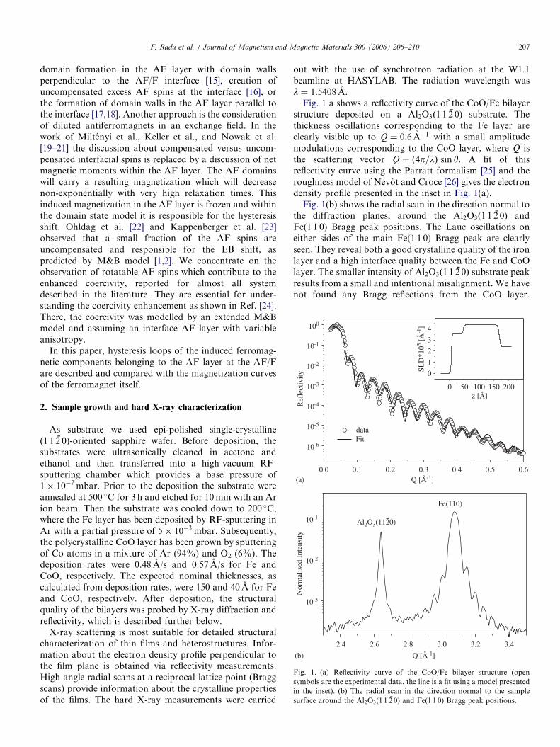
Fig. 2. The reflectivities of CoO/Fe bilayer measured at room temperature
for the magnetic field applied in the sample plane parallel (Iþ, closed
symbols) and antiparallel (I�, open symbols) to the photon helicity. The
energy of the circular polarized light was tuned close to the L3 absorption
edges of Co (a) and Fe (b), respectively.
700 720 740 760 780 800 820
-0.4
-0.2
0.0
0.2
0.4
0.6
0.8CoO L2
CoO L3
Fe L2
Asy
mm
etry
rat
io
Photon energy [eV]
Fe L3
Fig. 3. The energy dependence of the asymmetry ratio for a fixed
scattering angle of 2 y ¼ 32�.
F. Radu et al. / Journal of Magnetism and Magnetic Materials 300 (2006) 206–210208
Therefore we concluded that this layer is polycrystalline.The deposition temperature of the CoO was 200 �C, whichis the optimal growth temperature for polycrystalline CoO,obtained from detailed growth studies presented in Ref.[27]. The crystalline quality of cobalt oxide was intention-ally sacrificed in order to achieve a smooth CoO/Feinterface, and to eliminate orientational difficulties, char-acteristic for mono-crystalline CoO layers.
3. Soft X-ray resonant magnetic scattering studies
X-ray resonant magnetic scattering (XRMS) providesdirect information on the magnetic structure of materials.In order to study XRMS of 3d transition metals, the L
absorption edges must be utilized, which are located in thesoft X-ray range. Soft XRMS using either circularly orlinearly polarized X-rays, has proven to be a highly usefultechnique for the study of magnetic properties of buriedlayers, interfaces and, depth-dependent magnetic proper-ties. Moreover, by varying the external magnetic fieldapplied parallel to the sample plane and parallel to the X-ray circular helicity, close to energies corresponding to L
absorption edges, element-specific hysteresis loops can bemeasured [28]. The XRMS experiments were carried out atthe undulator beamlines UE56/1&2 and at the bendingmagnet beamline PM3 of BESSY. Since for this energyrange special vacuum conditions are required, a UHV-diffractometer ALICE [29] was used for the experiments tobe described below. The magnetic field was applied in thescattering plane and parallel to the sample surface.
3.1. Reflectivity and asymmetry ratio
Fig. 2 shows the reflectivities of CoO/Fe bilayermeasured at room temperature for the magnetic fieldapplied in the sample plane parallel ðIþÞ and antiparallelðI�Þ to the photon helicity. The photon energy of thecircular polarized light was tuned close to the L3
absorption edge of Co (Fig. 2(a)) and Fe (Fig. 2(b)),respectively. The highest magnetic sensitivity is reached atthe maxima of the thickness oscillations. The energydependence of the asymmetry ratio A ¼ ðIþ � I�Þ=ðIþ þI�Þ is depicted in Fig. 3 for a fixed scattering angle of2 y ¼ 32�. Strikingly, the asymmetry of Co does not vanishas expected for AF materials. Moreover, even above theNeel temperature (TN ¼ 291K) a ferromagnetic signalbelonging to the CoO layer is still visible.
The reflectivities shown in Fig. 2 reveal the sign of theinterfacial coupling of the two ferromagnetic materials inquestion, which share a common interface or which areexchange coupled over a non-magnetic layer. For bothlayers the minima in the Iþ reflectivity curve always lies atlower angles than the minima in the I� curves. This allowsto clearly conclude that the magnetization of both layers isparallel. An antiparallel alignment of the layers wouldproduce a reverse position of the minima in the reflectivitycurves. It should be pointed out that element-specific anti-
phase hysteresis loops is not characteristic for the couplingsign [30]. This can be seen from the reflectivity curves. Atsome incident angles the asymmetry is positive for Fe andnegative for CoO. Therefore, taken the hysteresis loopsalone they would suggest an AF-coupling between thelayers, whereas the true orientation is ferromagnetic, asclearly seen in the reflectivity curves.
3.2. Temperature dependence of the element-specific
hysteresis loops
The exchange bias hysteresis loops measured at the L3
absorption edges of Co (E ¼ 780 eV, closed symbols) and

ARTICLE IN PRESS
-600 -400 -200 0 200 400 600
T = 120K
T = 200K
T = 300K
Fe
CoO
T = 30K
H [Oe]
Inte
nsity
[a.
u.]
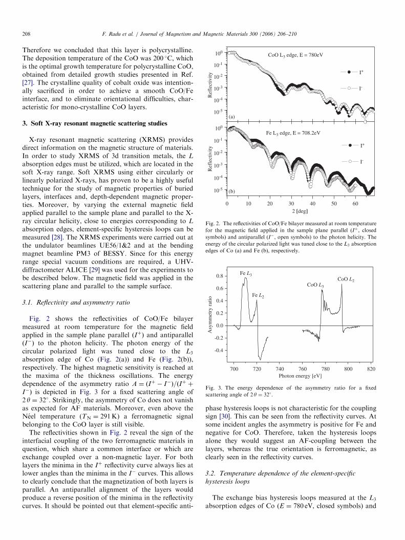
Fig. 4. The temperature dependence of the exchange bias hysteresis loops
measured at L3 absorption edges of Co (E ¼ 780 eV, closed symbols) and
Fe (E ¼ 708:2 eV, open symbols). Scattering angle is 2 y ¼ 32�.
F. Radu et al. / Journal of Magnetism and Magnetic Materials 300 (2006) 206–210 209
Fe (E ¼ 708:2 eV, open symbols) and for different tem-peratures are shown in Fig. 4. The measuring procedure isas follows: first the system was heated up to T ¼ 300K,which is well above the Neel temperature of CoO. Here, afield of þ2000Oe was applied parallel to the sample planeand parallel to the helicity of the circular polarization ofthe X-ray beam. Subsequently, the system was field cooledto the lowest available temperature, which is about 30K.Here, several hysteresis loops were measured (not shown)in order to eliminate training effects of the hysteresis loops.After acquiring a stable reversible magnetization curve at30K, we raised the temperature stepwise, from low to highT, and for each temperature we measured one element-specific hysteresis loop at the energies corresponding to Feand CoO, respectively. The hysteresis loops of Fe as afunction of temperature show a typical behavior. At lowtemperatures an increased coercive field and a shift of thehysteresis loop is observed. As the temperature is increased,the coercive field and the exchange bias decrease until theblocking temperature is reached. Here, the exchange biasvanishes and the coercive field shows little changes as thetemperature is further increased. Strikingly, a ferromag-netic hysteresis loop corresponding to the CoO layer isobserved for all temperatures, following closely thehysteresis loop of Fe (or vice versa), with some notabledifferences. It appears that the ferromagnetic componentsof CoO develop different coercive fields than Fe below the
blocking temperature. Moreover, the ferromagnetic mo-ment of CoO is present also above the Neel temperature.Here, the AF layer is in a paramagnetic state, therefore themagnetic moment per spin is very low for applied fieldsused here. It implies, that a ferromagnetic layer should bepresent at the interface between Fe and CoO with a Curietemperature, higher than the Neel temperature of CoO.
3.3. XRMS comparison between CoO single layer and
CoO/Fe bilayer system
In order to exclude the presence of Co clusters in theCoO layer as a possible explanations of our resultspresented above, we have prepared two additional sampleswith the same sputtering technique: one was the same CoO/Fe exchange bias system and another one grown in thesame run was just a simple CoO layer deposited on asapphire substrate. First both samples were field cooledand then we measured at low temperatures the element-specific hysteresis loops at the L3 absorption edge of Co.For the CoO/Fe bilayer the previous results werereproduced. But for the single CoO layer no ferromagneticsignal was observed. We infer from this the absence ofcobalt clusters in the CoO layer [31]. Vice versa, theferromagnetic moment in the CoO layer must be inducedby the proximity between the F and the AF layer. Theinduced magnetic moment appears to consist of two parts.One part of the spins are strongly coupled to the AF itself.They do not rotate with the rotation of the F layer.Another part of these spins have a reduced AF anisotropyand due to exchange coupling to the F layer, they show asimilar hysteresis loop as the F layer.
4. Discussion
The M&B model [1,2] assumes that the AF spins rigidlyform an AF state, but they may slightly rotate as a wholeduring the magnetization reversal of the F layer. Within theM&B model, enhanced coercivity is not accounted for. Theinterface is assumed to be perfectly uncompensated withthe interface AF spins having the same anisotropy as thebulk spins. However, the interface is never perfect.Roughness, deviations from stoichiometry, interdiffusion,structural defects, etc. cause non-ideal magnetic interfaces.It is therefore naturally to assume that, statistically, afraction of the AF spins have lower anisotropy ascompared to the bulk ones. These interfacial AF spinscan rotate together with the ferromagnet. They mediate theexchange coupling, induce an enhanced coercivity, butsoften the extreme coupling condition assumed by M&B.Therefore, we assume that the anisotropy of the AFinterface layer varies from K int ¼ 0 next to the F layer toK int ¼ KAF next to the AF layer, where KAF is theanisotropy constant of a presumably uniaxial antiferro-magnet. This variation of the anisotropy constant acrossthe interface governs the enhanced anisotropy of theferromagnetic layer. So far, it was believed that the

ARTICLE IN PRESSF. Radu et al. / Journal of Magnetism and Magnetic Materials 300 (2006) 206–210210
enhanced coercivity in F/AF exchange biased systems iscaused by compensated AF spins at the F/AF interface. Weargue that for most of the AF materials a compensated oruncompensated spin having the same anisotropy as thebulk AF layer would be practically impossible to reverse byrotating the F layer. Therefore we need to assume lowanisotropy AF spins in order to qualitatively describe therotating AF seen in the experimental data. Evidence for theexistence of low anisotropy AF spins at the F/AF interfaceis provided here through measurements of element-specifichysteresis loops.
5. Conclusions
We have investigated the ferromagnetic behavior of theAF spins for an Fe/CoO exchange bias bilayer. For alltemperatures we observe a non-vanishing ferromagnetichysteresis loop of the spins belonging to the AF layer. Theyreverse, in phase, with the spins of the Fe layer, but displaya different coercive field. We assume that those AF spinsare located at the interface between the F/AF layer, andthat they have, on average, a reduced AF anisotropy. Thisassumption may lead to a better understanding of theenhanced coercivity observed in almost all F/AF systems.
Acknowledgements
We would like to thank S. Erdt-Bohm for technicalassistance during sample preparation, Th. Kachel, B. Zada,W. Mahler (BESSY) and O. Seeck (HASYLAB) for theirhelp with the beamline operation. We gratefully acknowl-edge support through the SFB 491 ‘‘Magnetische Hetero-schichten: Struktur und elektronischer Transport’’ of theDFG and the German Federal Ministry of Education andResearch (BMBF) under Contracts No. 03ZA6BC2(ALICE diffractometer) and No. 05ES3XBA/5 (supportof travel to BESSY).
References
[1] W. Meiklejohn, C.P. Bean, Phys. Rev. 102 (1956) 1413.
[2] W. Meiklejohn, C.P. Bean, Phys. Rev. 105 (1957) 904.
[3] A.E. Berkowitz, K. Takano, J. Magn. Magn. Mater. 200 (1999)
552.
[4] J. Nogues, I.K. Schuller, J. Magn. Magn. Mater. 192 (1999) 203.
[5] R.L. Stamps, J. Phys. D 33 (2000) 247.
[6] M. Kiwi, J. Magn. Magn. Mater. 234 (2001) 584.
[7] F. Radu, M. Etzkorn, T. Schmitte, R. Siebrecht, A. Schreyer,
K. Westerholt, H. Zabel, J. Magn. Magn. Mater. 240 (2002)
251.
[8] M. Gierlings, M.J. Prandolini, H. Fritzsche, M. Gruyters, D. Riegel,
Phys. Rev. B 65 (2002) 092407.
[9] W.-T. Lee, S.G.E. te Velthuis, G.P. Felcher, F. Klose, T. Gredig,
E.D. Dahlberg, Phys. Rev. B 65 (2002) 224417.
[10] F. Radu, M. Etzkorn, R. Siebrecht, T. Schmitte, K. Westerholt,
H. Zabel, Phys. Rev. B 67 (2003) 134409.
[11] M.R. Fitzsimmons, P. Yashar, C. Leighton, I.K. Schuller, J. Nogues,
C.F. Majkrzak, J.A. Dura, Phys. Rev. Lett. 84 (2000) 3986.
[12] D.S. Geoghegan, P.G. McCormick, R. Street, J. Magn. Magn.
Mater. 177 (1998) 937.
[13] A.M. Goodman, H. Laidler, K. O’Grady, N.W. Owen, A.K. Petford-
Long, J. Appl. Phys. 87 (2000) 6409.
[14] F. Radu, M. Etzkorn, V. Leiner, T. Schmitte, A. Schreyer,
K. Westerholt, H. Zabel, Appl. Phys. A 74 (2002) S1570.
[15] A.P. Malozemoff, Phys. Rev. B 35 (1987) 3679.
[16] T.C. Schulthess, W.H. Butler, Phys. Rev. Lett. 81 (1998) 4516.
[17] D. Mauri, H.C. Siegmann, P.S. Bagus, E. Kay, J. Appl. Phys. 62
(1987) 3047.
[18] J.-V. Kim, R.L. Stamps, Phys. Rev. B 718 (2005) 094405.
[19] P. Miltenyi, M. Gierlings, J. Keller, B. Beschoten, G. Guntherodt,
U. Nowak, K.D. Usadel, Phys. Rev. Lett. 84 (2000) 4224.
[20] J. Keller, P. Miltenyi, B. Beschoten, G. Guntherodt, U. Nowak,
K.D. Usadel Phys. Rev. B 66 (2002) 014431.
[21] U. Nowak, K.D. Usadel, J. Keller, P. Miltenyi, B. Beschoten,
G. Guntherodt, Phys. Rev. B 66 (2002) 014430.
[22] H. Ohldag, A. Scholl, F. Nolting, E. Arenholz, S. Maat, A.T. Young,
M. Carey, J. Stohr, Phys. Rev. Lett. 91 (2003) 017203.
[23] P. Kappenberger, S. Martin, Y. Pellmont, H.J. Hug, J.B. Kortright,
O. Hellwig, Eric E. Fullerton, Phys. Rev. Lett. 91 (2003) 267202.
[24] F. Radu, A. Westphalen, K. Theis-Brohl, H. Zabel, J. Phys.:
Condens. Mat. (2005), accepted.
[25] L.G. Parratt, Phys. Rev. 95 (1954) 359.
[26] L. Nevot, P. Croce, Rev. Phys. Appl. 15 (1980) 761.
[27] G. Nowak, A. Remhof, F. Radu, H.-W. Becker, A. Nefedov, K.
Westerholt, H. Zabel, (2006), to be submitted.
[28] J.B. Kortright, J.S. Jiang, S.D. Bader, O. Hellwig, D.T. Marguiles,
E.E. Fullerton, Nucl. Instr. and Meth. B 199 (2003) 301.
[29] J. Grabis, A. Nefedov, H. Zabel, Rev. Sci. Instr. 74 (2003) 4048.
[30] C. Sanchez-Hanke, C.-C. Kao, J. Magn. Magn. Mater. 226–230
(2001) 1803.
[31] F. Radu, A. Nefedov, G. Nowak, J. Grabis, and H. Zabel, Appl.
Phys. Lett. (2006), submitted.