Soft-Saturation Power Inductors for Optimizing DC-DC ...
30
Soft-Saturation Power Inductors for Optimizing DC-DC Converter Performance
Transcript of Soft-Saturation Power Inductors for Optimizing DC-DC ...

Soft-Saturation Power Inductors for Optimizing DC-DC Converter Performance

Rev May 2012
The development of high performance power inductors with molded, distributed air-gap cores leads to size reduction and improvements in power supply efficiency.
Crucial parameters must be properly understood and specified clearly in order to maximize the benefits of these new inductor types.
Soft-saturation, molded inductors
Rev May 2012
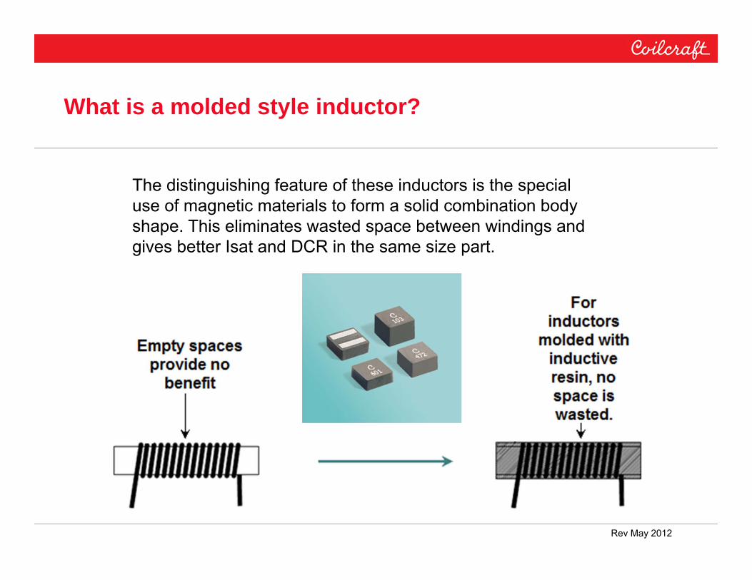
What is a molded style inductor?
The distinguishing feature of these inductors is the special use of magnetic materials to form a solid combination body shape. This eliminates wasted space between windings and gives better Isat and DCR in the same size part.

Rev May 2012
The General Power Inductor Design Challenge:
The goal is to maximize the L and Isat, and at the same time minimize R, size, and cost.
Therefore, we must understand the relationship between these parameters.

(1) Inductor value is a function of material propertiesand geometry
µ = Relative permeability• This is a material property. • Limited range of materials.
N = Turn count• Wide range possible.• Effective due to turns squared.
ae = Winding cross-section area (cm2)• Effective but increased size penalty.
le = Magnetic path length (cm)•I nteresting inverse relationship.
L = 4 µ × 10 H -9N A2e
el

(2) DC Resistance is also function of material property and geometry
= Volume Resistivity of the wire ( × cm)
• This is a material property
lW = Winding wire length (cm)
• Winding length depends both on the turn count and geometry
aW = Winding wire cross-section area (cm)
• Wire tables
DCR = ×lw
waaw
lw

(3) Saturation Current is a function of Material Properties and Geometry
Bsat = Material PropertyAe = Core cross sectionL = Needed InductanceN = Turn Count
L / A N B I esat sat

Self-lead inductor design

Rev May 2012
Example of molded inductor performance

Rev May 2012
Example of size reduction achieved by molded inductors

Benchmark
Part No. L DCR typ. Isat (20% Ldrop)
IHLP2525CZ‐01 1 µH 9.00 mΩ 22 A
IHLP2525CZ‐06 1 µH 8.44 mΩ 22 A
XAL7030 1 µH 4.55 mΩ 20A
The XAL7030 performance is shown here against the closest industry standard inductor family, but these should not be viewed as alternates. The Coilcraft XAL inductor families represent the next-generation of superior technology. The example here shows Coilcraft XAL7030 to have superior, low DCR, about half the competition.
The winner.

Mechanically Strong
These inductors are solid, strong shapes. They are quite rugged and suitable for high stress environments like portable electronics and automotive.

Magnetic Shielding
The use of magnetic resins throughout the coil body insures the best possible reduction of harmful EMI emissions. Components can be placed closer together for highest pcb density.
Normal TypeLtra Type

Ltra means Reliability – Superior Materials
Some inductor core materials exhibit a negative property called thermal aging. When thermal aging happens to inductors, the efficiency gets worse with the application of time and temperature. The efficiency loss causes more heat, which again lowers the efficiency, leading to more heat….and so on…inductors and circuits can be heated beyond acceptable ratings…sometimes with disastrous effects.
Coilcraft Ltra materials have been specially engineered to eliminate thermal aging concerns. The comparison below shows how some inductors sold today exhibit increased loss when subjected to thermal aging. The Coilcraft Ltra inductors have no such problem.

Rev May 2012
Soft saturation

Rev May 2012
The soft saturation characteristic for molded inductors requires rethinking the definition of saturation. Where does saturation begin for the molded style?

Rev May 2012
Saturation defined the traditional way, by inductance drop.

Rev May 2012
The concept of Inductance @ Current.
The linearity of the “curves” makes it feasible to read the pertinent information directly for the exact operating point of interest.
Rev May 2012
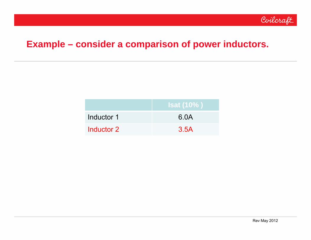
Example – consider a comparison of power inductors.
Isat (10% )Inductor 1 6.0A
Inductor 2 3.5A

Rev May 2012
The higher Isat rating of Inductor 1 comes with a tradeoff of higher DCR.
Isat (10% ) DCRInductor 1 6.0A .015 ΩInductor 2 3.5A .010 Ω

Rev May 2012
Here are the saturation curves for Inductor 1 and Inductor 2. Is inductor 1 two times better?
Isat (10% )Inductor 1 6.0A
Inductor 2 3.5A

Rev May 2012
Ldrop comparison

Rev May 2012
The “inductance drop” definition assumes there is a distinct saturation region. It is the vertical portions of the curves that can be meaningfully compared in the horizontal direction.
Rev May 2012
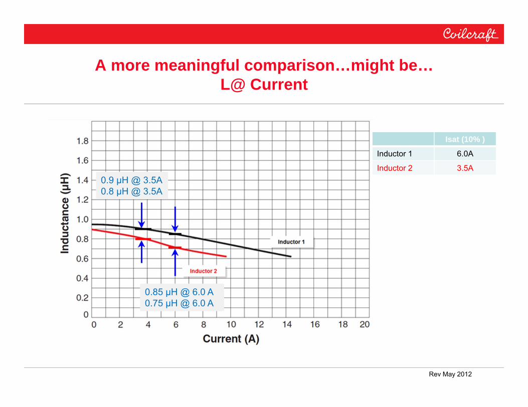
A more meaningful comparison…might be…L@ Current
0.9 µH @ 3.5A0.8 µH @ 3.5A
0.85 µH @ 6.0 A 0.75 µH @ 6.0 A
Isat (10% )
Inductor 1 6.0A
Inductor 2 3.5A

Rev May 2012
Preview – New tool coming soon

Rev May 2012
The Inductance at Current Finder provides results for the exact operating conditions of interest to the converter designer.

Rev May 2012
Select parts of interest for more detailed analysis.

Rev May 2012
“Curves on Demand”

Rev May 2012
Inductance @ Current “Curves on Demand” a key feature

Rev May 2012
Conclusions
New characterization data allows the user to take full advantage of the possibilities for size and efficiency improvement offered by new power inductors.