
Soft ground? No problem! - Civil Departmentdhingra/ce152_files/ce152_ajuneja.pdf · • Remove the...
57
Surface compaction using a giant tamper to compact loose soil (2006 AD) Department of Civil Engineering Department of Civil Engineering Indian Institute of Technology Bombay Indian Institute of Technology Bombay Email: Email: [email protected] [email protected] Tel # 2576 7327 Tel # 2576 7327 Soft ground? No problem! Prof Ashish Juneja Surface densification to increase soil strength (11 th Century Chinese Building Standards) CE 152 Introduction to Civil Engineering
Transcript of Soft ground? No problem! - Civil Departmentdhingra/ce152_files/ce152_ajuneja.pdf · • Remove the...

Surface compaction using a giant tamper to compact loose soil (2006 AD)
Department of Civil EngineeringDepartment of Civil EngineeringIndian Institute of Technology BombayIndian Institute of Technology Bombay
Email: Email: [email protected]@iitb.ac.inTel # 2576 7327Tel # 2576 7327
Soft ground? No problem!
Prof Ashish Juneja
Surface densification to increase soil strength (11th
Century Chinese Building Standards)
CE 152 Introduction to Civil Engineering

What is soft ground?
• Any soil which is susceptible to failure or cause excessive settlement when superstructure is constructed over it
• Types of soils classified as soft:Saturated clays and fine silts (alluvium), marine clays and fine siltsLoose sand (especially when under water table)

Significant development in the past 50 years with the introduction of composer piles, deep mixing and new injection materials

Physical modelling of ground modification…where are we now?
Vertical reinforcement subjected to combined loading

Excavation support systems

Ground improved using deep mixing
Deformations of grouted ground around tunnel

Vibro pile installation

Soft ground?.....available options
You can:
• Redesign the structure and its foundations for support by the poor soil
• Bypass the site - by moving to a new site e.g. highway route planning
• Remove the poor soil and replace it with a good one
• Treat the soil in-place and improve its properties
The methods which are capable of improving certain characteristics of the soft ground for civil engineering construction are all considered as ground improvement techniques

Worker safety during geotechnical construction

Factors influencing the choice of improvement method:
1. Purpose of the improvement project2. Time factor3. Area and depth of soil to be treated4. Type of soil and its initial properties5. Material availability6. Equipment and skills available7. Environment factors8. Local experience and preference9. Feasibility of construction10.Cost

Geotechnical engineering criteria used in evaluating a site:
1. Bearing capacity2. Settlement3. Seepage4. Long term stability and durability5. Liquefaction stability6. Environmental problems
Kansai International Airport
Leaning Tower of Pisa

Methods of ground improvement
1. Over-excavation or replacement method2. Densification and compaction (mechanical
modification)3. Hydraulic modification: “Free” excess water is
extracted e.g. use of pumping, vertical drains and surcharge
4. Admixture stabilisation: Physically mixing of additives with surface soils or soils at depthAdditives include: natural soils, lime, cement or
industrial by product and waste material

Methods of ground improvement5. Reinforcement method:
- Vertical reinforcement (e.g. piles, stone columns)- horizontal reinforcement (e.g. soil nailing, geosynthetic products)
6. Electrical modification methods: Using electrical gradient to cause water movement
7. Thermal modification methods: Heating the ground can cause permanent change in the soil mineral structure; Freezing bonds individual particles together for temporary soil improvement

Instrumentations, monitoring and evaluating the level of
improvement
How do you know that the ground improvement measures that you have done achieve what you want?
- install some instruments to verify it!!

Two categories of measuring instruments:Tests conducted before and after ground improvement:-
(i) Density & water content measurement(ii) Strength and stiffness e.g. SPT, CPT)(iii) Compressibility and Permeability
Tests to measure continuous performance:-
(i) Stress measurement; and(ii) Deformation or strain measurement

Earth pressure measurement
Choice of instrument:
1. Property or parameter to be measured e.g. density, GWT, etc.
2. Operating principle e.g. standpipe, dipmeter, piezometer and PPT, amongst others
3. Reliability: range -vs- sensitivity; consistency and range of soils for it to be suitable for testing
4. Data logging: equipment, logging method and frequency
5. Data interpretation – what these data mean?

Overexcavation and replacement
B to 3B
0.5B to 1.5B
B
If good bearing stratum exists close to the footing level, then excavation should be taken
to the top of the bearing stratum

Principle of overexcavation and replacement
Excavate poor or inadequate bearing material and either:(a) Stabilise, dry or wet and recompact the excavated material(b) Replace it with stiffer and stronger material
Replaced material is usually sand, gravel or sand-gravel mixes
Compaction is usually done in lifts (typically 150mm)
Settlement is reduced and bearing capacity is increased

Failure modes
Plane strain shear failure
Plane strain cavity expansion
AWtpHctanpPqq uh
bult−+φ
+=
( )
φ
++γ=2
45tanc2Dq 2uult

Choice of φ values: plane strain or triaxial value?
φps = φtx for φtx ≤ 34o
φps = 1.5φtx – 17o for φtx > 34o
Values of φ from direct shear tests are usually about 1 to 2o
greater than φtx for the same range of confining stresses

Settlement
As per IS 8009 (Part I)-1976 (Amendment 1 and 2, 1981, 1990), elastic or immediate settlement at the corner of flexible footing is derived from the following equation,
F21
2II
121I
E1qBH
ν−ν−
+
ν−=∆

Limitation of overexcavation / replacement
• Slope protection during excavation
• Adjacent structures
• Pumping required for high ground water table conditions
• Replacement material not readily available
• Limited compaction achieved in confined areas (use vibratory plates compactor or high frequency rammer)

Precompression / preloading with vertical drains
Precompression/preloading refers to the process of compressing foundation soils under applied vertical stress prior to placement of the final permanent construction load.
It is a method of pre-empting potentially damaging settlements on soft soil
increases the bearing capacity & reduces the compressibility of weak ground
Preloading is only cost effective when large area is to be improved
Vertical drains accelerate settlements but do not reduce final movement

Methods of producing surcharge:
(1) Earth fill or embankment (most common)(2) Water filled tanks(3) Vacuum preloading: by pumping from beneath an
impervious membrane placed over the ground surface
(4) Ground water lowering: there is an increase in effective stress which is equal to the unit weight of water times the drawdown height
(5) Consolidation by electro-osmosis

Main applications:
•Foundations for:Embankments
Liquid storage tanks
Buildings (less common)
Where soil properties and/or stress conditions vary with depth, it may be necessary to analyse the profile as a series of sub-layers.

Vertical drains and preloading
• Vertical drains are effective in inorganic clays and silts (exhibit primary consolidation); and if the deposits contain thin horizontal sand or silt lenses (Ch>> Cv)
• Secondary consolidation settlement which is essentially a creep phenomenon is not speeded up by vertical drains

Vertical Drains
Broadly classified into two categories:
o Sand drains
o Geosynthetic drains or prefabricated vertical (PV) drains

Sand Drains
• Typically 200 to 500mm in dia• Formed by infilling sand into a hole in the ground• Hole formed by driving, jetting or augering• Typical spacing: 1.5 to 6.0m• Large diameter sand drains tend to behave as
“weak piles” in soft soils. This may have the effect of stress concentration on the drains

Prefabricated Vertical (PV) drains
• Band shape drains consists of a central core wrapped around by a filter layer
• kfilter > ksoil
• The filer should retain fine soil particles• PV should be strong enough to resist
installation stresses• Equivalent diameter ( )
π+
= tB2de

Advantages of PV drain1 Creates less disturbance to host soil2 Rapid installation3 Installation equipment is lighter4 Eliminates cost of sand backfill and water5 Does not require disposal of soil waste6 Continuity of drain is maintained
1 Ground settlement can cause the PV drain to buckle; hence reduce drain efficiency
2 Cannot bear vertical loads
Limitation of PV drain

Other design considerations for PV drainsEffect of smear• Permeability in the narrow zone of remoulded soil
is reduced; slows down the radial consolidation
Effect of wall resistance• Deterioration of filter can significantly reduce de
• Clogging/siltation of filter drain by fine particles can decrease the area available for flow
• Folding of drain due to soil settlement can decrease the discharge capacity

load
time
Settlement
∆Pp∆Pp+∆Pf
SpSp+f
∆Pp = Structural load
∆Pf = Surcharge load
Relation between surcharge and degree of consolidation
fp
pavg S
SU
+=
∆+
+=
o
po
o
cp P
PPlogH
e1CS
∆+∆+
+=
o
fpo
o
cp P
PPPlogH
e1CS

Uavg and timeCarillo’s average degree of consolidation
2h
h DtCT =
( )( )hvavg U1U11U −−−=
Average degree of consolidation for vertical drainage
[ ]2vv U
4T
π= for Uv ≤ 60%
( )vv U100log933.0781.1T −−= for Uv > 60%
Average degree of consolidation for radial drainage
2v
v HtCT =
where
where
−−=
mT8exp1U h
h
( )2
2
2
2
n41n3nln
1nnm
−−
−=where
n (drain spacing ratio) = D/de

Observational methods of monitoring consolidation
Hyperbolic method
Asaoka’s method

Hyperbolic method - Settlement-time plot in terms of Uavg (avg degree of consolidation) and Tv (time factor)
3 regions:
Region 1: Concave downwards from origin.
Region 2: Linear portion between Tv = 0.25 and Tv = 0.848. These points correspond to U60 and U90.
Region 3: Second linear portion for Tv > 1.0 which approaches the 45 degree line

Using the inverse slope approach, the total primary consolidation δult, is estimated as α/Si.
α= i60
S6.0
1S
α= i90
S9.0
1S

Procedure for using the hyperbolic plot method
Step 1 Plot field settlement data as t/δ vs t; where t = time and δ = settlement from the start of constant load applicationStep 2 Identify first linear segment and measure its slope Si (corresponding to data between δ60 and δ90)Step 3 From n, Ch/Cv and H/D, determine the theoretical slope α from Fig. 3Step 4 Calculate the total primary consolidation settlement from theoretical slope α and Si, that is δult= α/Si
Step 5 Calculate the slope of lines

Step 6 Construct these lines and locate δ60 and δ90 points.The total primary settlement is estimated from
All 3 values should be close to one another
α= i60
S6.0
1S
α= i90
S9.0
1S
9.0or
6.0or
S9060
iult
δ=
δ=
α=δ

Asaoka’s method - Readings taken at constant time interval ∆t or equivalent values interpolated from the time-settlement curve
Step1 Plot Settlement δnversus preceding settlement δn-1
Step 2 Draw a line through the points plotted and extrapolate to intersect with the 450 line (note: irregular early points are ignored in the standard analysis)
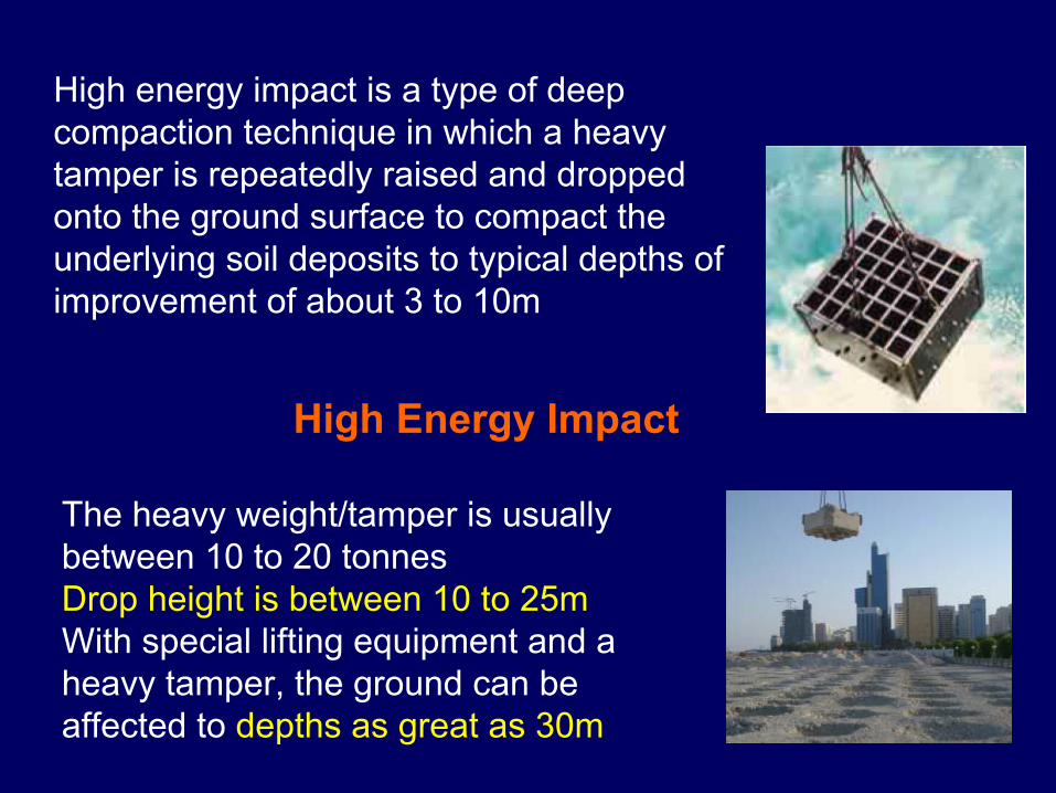
High Energy Impact
High energy impact is a type of deep compaction technique in which a heavy tamper is repeatedly raised and dropped onto the ground surface to compact the underlying soil deposits to typical depths of improvement of about 3 to 10m
The heavy weight/tamper is usually between 10 to 20 tonnesDrop height is between 10 to 25mWith special lifting equipment and a heavy tamper, the ground can be affected to depths as great as 30m

Variant of this technique are:
1. Dynamic compaction (DC): The stress waves generated by the impact travel to considerable depths to rearrange the particles into a dense configuration.
Dynamic compaction carried out in the trial area of Changi East Reclamation Project
(mass 25 tons, drop height 25 m)
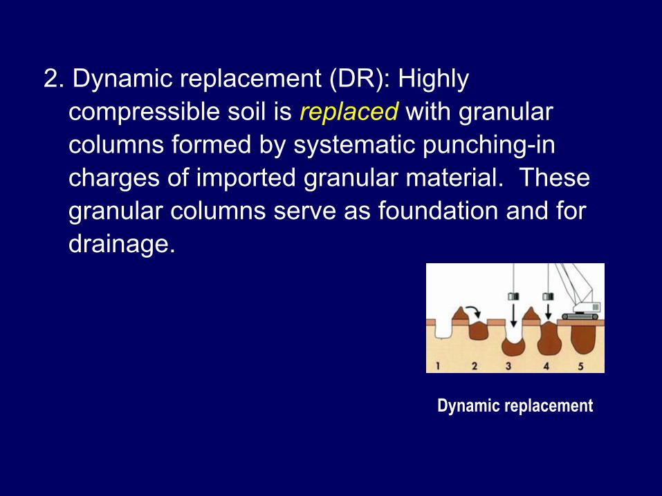
2. Dynamic replacement (DR): Highly compressible soil is replaced with granular columns formed by systematic punching-in charges of imported granular material. These granular columns serve as foundation and for drainage.
Dynamic replacement

3. Dynamic replacement and mixing (DRM): The granular column formed by DR is further subjected to very high impact resulting in rupture of the surrounding soft peaty soil and direct mixing of the granular material into the peaty soil.
Mechanism of DR and DRM

Applications of high energy impact:
• Roads, highways, railroads, airport runways, taxiways, aprons
• Storage areas, Oil tanks• Housing development• Industrial plants• Ports• Reclaimed land

Equipment• Tampers raised and dropped with a conventional
heavy crawler crane using a single cable with a free spool
• Tampers constructed of steel or steel shells filled with sand or concrete (area of tamper ~ contact pressure 40 to 75kPa
• Tampers are square, circular or octagonal• Impact points are spaced to prevent the creation
of dense zone of material at intermediate depth• Spacing between primary impact points ~
maximum depth to be improved

Ground vibrations produced by high energy impact may be undesirable in built-up areas (this can be reduced by having trenches around the area being compacted; as the trenches would stop the vibrations from transmitted further).

Deposits suitable for improvementCoarse grained pervious deposits (less than 35% silt)
Immediate response is observed; energy causes the particles to reorient themselves into a denser packing
Permeability of these deposits is high that, the pore pressure generated during tamping dissipate within a short time

Semi-pervious deposits (less than 25% clay and PI< 8)The energy applied is effective in partially
saturated soils (MC less than the plastic limit)In saturated or near saturated semi-pervious
deposits, the induced excess pore pressures may require days or weeks to dissipate. Therefore, rest period is required between two phases/passes

Saturated impervious depositsThese soils are nearly impervious to
water and are generally NOT suitable for dynamic compaction
The applied energy produces distortion of the soil mass. Hence, no significant densification occurs and the ground surface around the crater heaves
CraterOriginal ground surface
Pounder Heave

Lukas (1986)
Summary of particle size suitable for DC

Depth of improvement
WHD α=
where D = depth of improvement (m)W = weight of the pounder (tonnes)H = drop height (m)α = empirical coefficient
For granular soils, α is typically taken to be 0.5

Typical range of design parametersPounder: Steel or concrete blocks
Weight W= 10 to 20 tonnesDimension: 1.5 to 2m square
(Circular up to 5m dia)Drop height: H = 10 to 20mTotal energy I = 100 to 400 tm/m2
Grid/print spacing S = 3 to 8m (square grid)No of blows per pass 5 to 15 (Rest period is to be
given in clayey and silty soils)No of passes 2 to 8

Applied energy and crater depth

Planning the field procedures
• Test Program• Area to densify• Position of water table• Print spacing• Drops per print• Number of passes• Ground levelling and surface compaction• Pore water pressure monitoring

Monitoring the improvement(a) Crater depth measurementCrater volume calculated from diameter and depth of crater; the measurement used in identifying local weak spots(b) Average ground settlementFollowing a complete pass, the ground surface is levelled. The average ground settlement or enforced settlement is indicative of the improvement(c) Field / in-situ testsCommonly used field tests: SPT, CPT, PMT

The quick landslide in Rissa, Norway 1978