SOFA SLIDEOUT SYSTEM OPERATION AND SERVICE M · “STROKE.” Ice or mud build-up during travel is...
20
OPERATION AND SERVICE MANUAL SOFA SLIDEOUT SYSTEM
Transcript of SOFA SLIDEOUT SYSTEM OPERATION AND SERVICE M · “STROKE.” Ice or mud build-up during travel is...
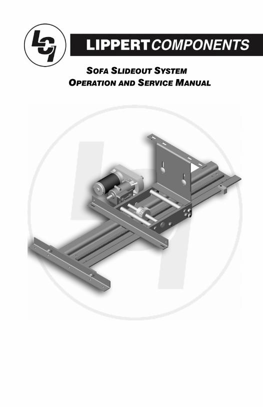
OPERATION AND SERVICE MANUAL SOFA SLIDEOUT SYSTEM
TABLE OF CONTENTS
SYSTEM…………………………………………………… Warning……………………………………….. Description…………………………………….. Prior to Operation……………………………
OPERATION………………………………………………
Main Components…………………………… Mechanical……………………………….. Electrical…………………………………..
Operating System….……………………….. Extending Slideout Room……………. Retracting Slideout Room…………… Manual Operation……………………….
Preventative Maintenance……………….. Electrical Maintenance………………. Mechanical Maintenance…………… SERVICE………………………………………………….. Troubleshooting………………………………
Chart………………………………………… Power Unit…………………………………
Wiring Diagram…………………………. Ordering Parts……………………………….. WARRANTY……………………………………………….
3 3 3 4
5 5 5 6 7 7 7 8
11 11 12
13 13 14 15 16 17
18
SYSTEM
WARNINGFAILURE TO ACT IN ACCORDANCE WITH THE FOLLOWINGMAY RESULT IN SERIOUS PERSONAL INJURY OR DEATH.
The Lippert Sofa Slideout System is intended for the solepurpose of extending and retracting the slideout room.It’s function should not be used for any other purpose orreason and to actuate the slideout room. To use thesystem for any reason other than what it is designed formay result in damage to the coach and/or cause seriousinjury or even death.
Before actuating the system, please keep these things inmind:
1. Parking locations should be clear of obstructions thatmay casue damage when the slideout room is actuated.
2. Be sure all persons are clear of the coach prior to theslideout room actuation.
3. Keep hands and other body parts away from slideoutmechanisms during actuation. Severe injury or death mayresult.
4. To optimize slideout actuation, park coach on solid andlevel ground.
DESCRIPTION
The Lippert Sofa Slideout System is a rack and pinion style slide system.Utilizing a bi-directional electric motor to actuate the drive shaft, theslideout room is extended and retracted from the same source. Theactuator has a built-in automatic clutching feature. The Lippert SofaSlideout System is designed as a negative or positive ground system.
There are no serviceable parts within the electric motor. If the motorfails, it must be replaced.
Disassembly of the motor voids the warranty.
Mechanical portions of the slideout system are replaceable. ContactLippert Components, Inc. to obtain replacement parts.

PRIOR TO OPERATION
Prior to operating the Lippert Sofa Slideout System, follow these four (4)guidelines:
1. Coach should be parked on the most level surface available.2. The PARKING BRAKE must be engaged.3. The coach’s transmission must be in NEUTRAL or PARK.4. The coach’s ignition must be in the RUN position or the coach’s engine must be running. (Class A and C only)
OPERATION
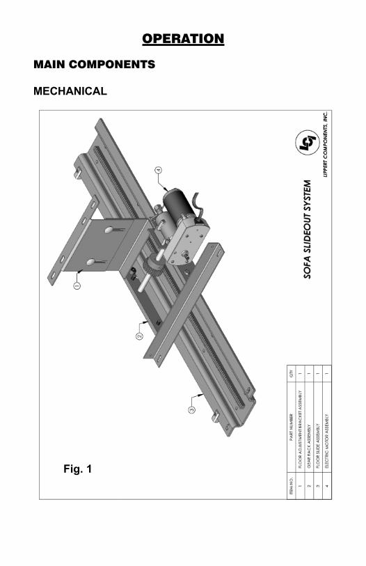
MAIN COMPONENTS
MECHANICAL
Fig. 1
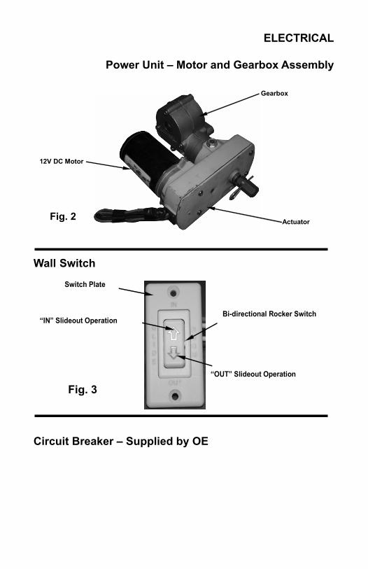
12V DC Motor
Actuator
Gearbox
Fig. 2
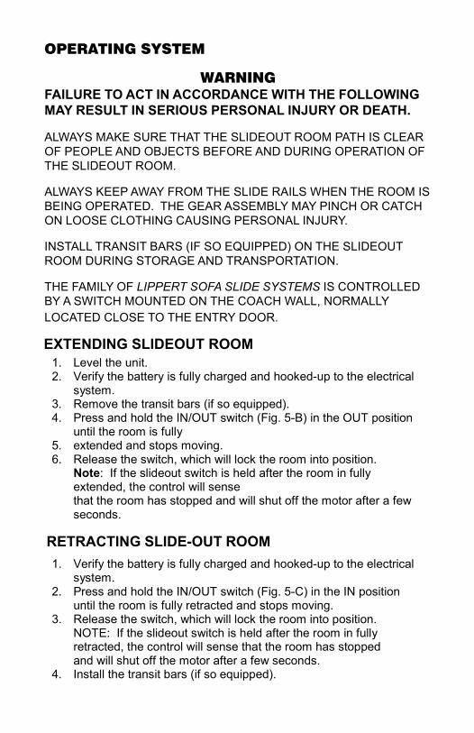
Switch Plate
“IN” Slideout Operation
“OUT” Slideout Operation
Bi-directional Rocker Switch
Fig. 3
ELECTRICAL
Power Unit – Motor and Gearbox Assembly
Wall Switch
Circuit Breaker – Supplied by OE
OPERATING SYSTEM
WARNINGFAILURE TO ACT IN ACCORDANCE WITH THE FOLLOWINGMAY RESULT IN SERIOUS PERSONAL INJURY OR DEATH.
ALWAYS MAKE SURE THAT THE SLIDEOUT ROOM PATH IS CLEAROF PEOPLE AND OBJECTS BEFORE AND DURING OPERATION OFTHE SLIDEOUT ROOM.
ALWAYS KEEP AWAY FROM THE SLIDE RAILS WHEN THE ROOM ISBEING OPERATED. THE GEAR ASSEMBLY MAY PINCH OR CATCHON LOOSE CLOTHING CAUSING PERSONAL INJURY.
INSTALL TRANSIT BARS (IF SO EQUIPPED) ON THE SLIDEOUTROOM DURING STORAGE AND TRANSPORTATION.
THE FAMILY OF LIPPERT SOFA SLIDE SYSTEMS IS CONTROLLEDBY A SWITCH MOUNTED ON THE COACH WALL, NORMALLYLOCATED CLOSE TO THE ENTRY DOOR.
1. Level the unit. 2. Verify the battery is fully charged and hooked-up to the electrical
system. 3. Remove the transit bars (if so equipped). 4. Press and hold the IN/OUT switch (Fig. 5-B) in the OUT position
until the room is fully 5. extended and stops moving. 6. Release the switch, which will lock the room into position.
Note: If the slideout switch is held after the room in fully extended, the control will sense that the room has stopped and will shut off the motor after a few seconds.
1. Verify the battery is fully charged and hooked-up to the electrical system.
2. Press and hold the IN/OUT switch (Fig. 5-C) in the IN position until the room is fully retracted and stops moving.
3. Release the switch, which will lock the room into position. NOTE: If the slideout switch is held after the room in fully retracted, the control will sense that the room has stopped and will shut off the motor after a few seconds.
4. Install the transit bars (if so equipped).
EXTENDING SLIDEOUT ROOM
RETRACTING SLIDE-OUT ROOM

B
Fig. 5 - Slideout Switch and Switch Plate
C
1. Locate coach’s house battery and disconnect the leads. 2. Access the slideout mechanism. Note: This is an above floor style slideout. The motor and slideout mechanism is located inside the coach.
Fig. 6
MANUAL OPERATION
The ABF-24-711-18:1 is equipped with a backup auxiliary power (BAP)system that allows you to extend or retract a room if the rooms do notmove when switch is pushed.
Check the troubleshooting guide on pages 10-13 for possible solutionsbefore using the backup auxiliary system.
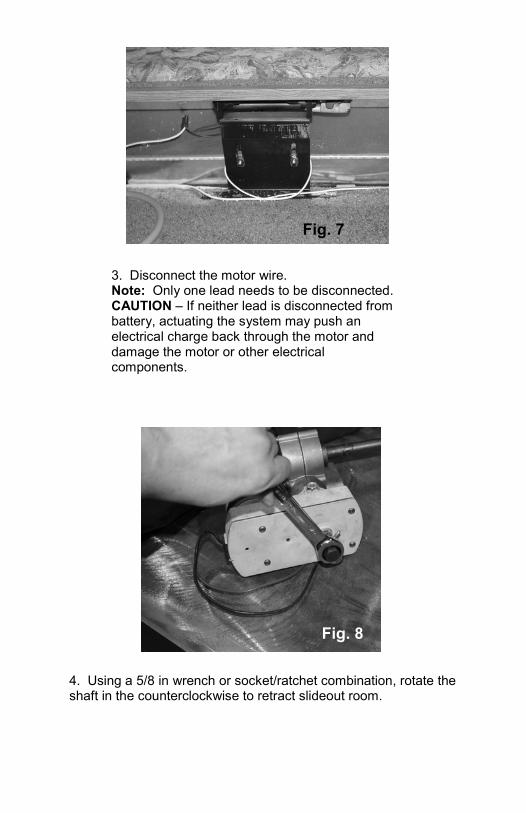
3. Disconnect the motor wire. Note: Only one lead needs to be disconnected. CAUTION – If neither lead is disconnected from battery, actuating the system may push an electrical charge back through the motor and damage the motor or other electrical components.
Fig. 7
4. Using a 5/8 in wrench or socket/ratchet combination, rotate the shaft in the counterclockwise to retract slideout room.
Fig. 8
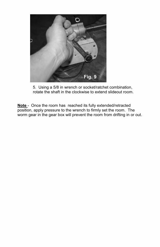
Note - Once the room has reached its fully extended/retracted position, apply pressure to the wrench to firmly set the room. The worm gear in the gear box will prevent the room from drifting in or out.
5. Using a 5/8 in wrench or socket/ratchet combination, rotate the shaft in the clockwise to extend slideout room.
Fig. 9
PREVENTATIVE MAINTENANCE
The Lippert Sofa Slideout System has been designed to require verylittle maintenance and has been static tested to over 2,500 continuouscycles with out any noticeable wear to rotating or sliding parts. Nogrease or lubrication is necessary and in some situations may bedetrimental to the environment and long term dependability of thesystem. To ensure the long life of your slideout system, read and followthese few simple procedures.
ELECTRICAL SYSTEM MAINTENANCE
For optimum performance, slide-out system requires full battery currentand voltage. The battery must be maintained at full capacity. Other thangood battery maintenance, check the terminals and other connections atthe battery, the control switch, and the electric motor for corrosion, andloose or damaged terminals. Check motor leads under the motorhomechassis. Since these connections are subject to damage from roaddebris, be sure they are in good condition.
Note: The Lippert Sofa Slideout System is designed to operate as anegative ground system. A negative ground system utilizes the chassisframe as a ground and an independent ground wire back to battery isnecessary (see page 12 for wiring diagram). It is important that theelectrical components have good wire to chassis contact. Over 90% ofunit electrical problems are due to bad ground connections.
MECHANICAL MAINTENANCE
Although the system is designed to be almost maintenance free, inspectthe slideout for any visible signs of external damage after and beforemovement of the room. Remember to inspect inside the coach as wellas the slideout system outside the coach.
Note: For long-term storage: It is recommended that the room beclosed (retracted).
• When the room is out, visually inspect the Slide Floor and DriveBox Assemblies. Refer to Fig. 1 for location of rail assemblies.Check for excess build-up of dirt or other foreign material; removeany debris that may be present.
• If the system squeaks or makes any noises it is permissible toapply a coat of lightweight oil to the drive shaft and roller areas butremove any excess oil so dirt and debris do not build-up. DO NOTuse grease.
WARNINGDO NOT WORK ON YOUR SLIDEOUT SYSTEM UNLESS THE
BATTERY IS DISCONNECTED.FAILURE TO ACT IN ACCORDANCE WITH THE FOLLOWING MAY
RESULT IN SERIOUS PERSONAL INJURY OR DEATH.
SERVICE
TROUBLESHOOTING
The Lippert Sofa Slideout System is only one of four inter-relatedslideout soom system components. These four components are asfollows: chassis, slideout room coach and Lippert Sofa Slideout System.Each one needs to function correctly with the others or misalignmentproblems will occur.
Every coach has it’s own personality and what may work to fix one coachmay not work on another even if the symptoms appear to be the same.
When something restricts room travel, system performances will beunpredictable. It is very important that slide rails, inner and outer, befree of contamination and allowed to travel freely the full distance or“STROKE.” Ice or mud build-up during travel is an example of sometypes of contamination that may occur.
When beginning to troubleshoot the system, make sure the battery isfully charged, there is no visible signs of external damage to theactuator, motor or rails and that the motor is wired properly and allconnections are secure.
You can adjust room extension by modifying the position of the rack gearon the slide floor rail to the spur gear on the gear assembly.
During troubleshooting, remember, by changing, altering or adjustingone thing, it may affect something else. Be sure any changes do notcreate a new problem.
Additional information on the Lippert Sofa Slideout System bycalling 866-524-7821 and asking for technical assistance.
IF YOU HAVE ANY PROBLEMS OR QUESTIONS CONSULT YOURLOCAL AUTHORIZED DEALER OR CALL LIPPERT AT:
(866) 524-7821.

ROOM DOESN'T MOVE WHEN SWITCH IS PRESSEDPROBABLE CAUSE CORRECTIVE ACTIONRestriction or obstruction inside or outside of unit Check for and clear obstruction
Low battery voltage, blown fuse, defective wiring Check battery voltage and charge if needed
Find and check fuse, replace if blown. Check
battery terminals and wiring. Look for loose
disconnected or corroded connectors.
Excessive room drag Check that transit bars are removed
POWER UNIT RUNS, ROOM DOES NOT MOVEMotor turns, room does not move Gear key is broken or lost, replace gear
drive assembly
Broken gear on drive shaft Replace gear drive assembly
Broken gear in gearbox Replace motor/gearbox assembly
Bad motor or gearbox Replace motor/gearbox assembly
POWER UNIT RUNS, ROOM MOVES SLOWLYLow battery, poor ground, extremely low Charge battery, check ground wire
temperature
Room in bind Adjust to proper room setting
Incorrect height adjustment Check for proper room height
ROOM STARTS TO MOVE AND STOPSObstruction of room inside or outside Check for and remove any obstruction
Dirts or corrosion build up on mechanism Clean dirt or corrosion and coat
LIGHTLY with oil
ROOM CHATTERS DURING OPERATIONTeeth on gear drive broken or worn Replace gear drive assembly
Teeth on inner rail broken or worn Replace inner rail assembly
TROUBLESHOOTING CHART
The folowing troubleshooting chart outlines some common problems, their causes andpossible corrective actions. When reference is made to a “Power Unit,” the termincludes the motor and the actuator as a complete unit. All Power Units are shippedfrom the factory with a serial number and date code, which should be given to theservice technician when asking for assistance.
Notes:If the slideout room will not retract there is a manual override that is located on theopposite side of the slideout room. A crank handle is provided with your unit. Once youhave the room in the closed position take you unit to the closest dealer. See pages 9-11for Manual Override Instructions.
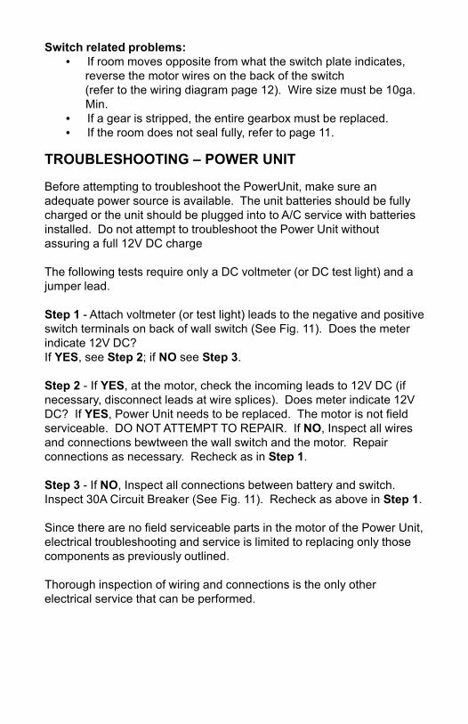
Switch related problems:• If room moves opposite from what the switch plate indicates, reverse the motor wires on the back of the switch (refer to the wiring diagram page 12). Wire size must be 10ga. Min.• If a gear is stripped, the entire gearbox must be replaced.• If the room does not seal fully, refer to page 11.
TROUBLESHOOTING – POWER UNIT
Before attempting to troubleshoot the PowerUnit, make sure anadequate power source is available. The unit batteries should be fullycharged or the unit should be plugged into to A/C service with batteriesinstalled. Do not attempt to troubleshoot the Power Unit withoutassuring a full 12V DC charge
The following tests require only a DC voltmeter (or DC test light) and ajumper lead.
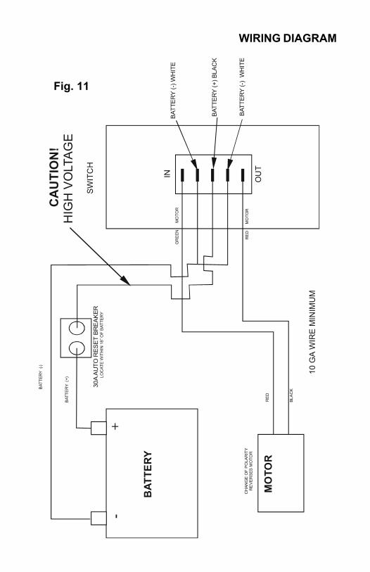
Step 1 - Attach voltmeter (or test light) leads to the negative and positiveswitch terminals on back of wall switch (See Fig. 11). Does the meterindicate 12V DC?If YES, see Step 2; if NO see Step 3.
Step 2 - If YES, at the motor, check the incoming leads to 12V DC (ifnecessary, disconnect leads at wire splices). Does meter indicate 12VDC? If YES, Power Unit needs to be replaced. The motor is not fieldserviceable. DO NOT ATTEMPT TO REPAIR. If NO, Inspect all wiresand connections bewtween the wall switch and the motor. Repairconnections as necessary. Recheck as in Step 1.
Step 3 - If NO, Inspect all connections between battery and switch.Inspect 30A Circuit Breaker (See Fig. 11). Recheck as above in Step 1.
Since there are no field serviceable parts in the motor of the Power Unit,electrical troubleshooting and service is limited to replacing only thosecomponents as previously outlined.
Thorough inspection of wiring and connections is the only otherelectrical service that can be performed.
B
ATTE
RY
MO
TOR
R
ED
CH
ANG
E O
F P
OLA
RIT
Y R
EV
ER
SES
MO
TOR
GR
EE
N
M
OTO
R
10 G
A W
IRE
MIN
IMU
M
30A
AU
TO R
ESE
T B
RE
AK
ER
LOC
ATE
WIT
HIN
18”
OF
BAT
TER
Y
IN
SWIT
CH
BAT
TER
Y (-
) WH
ITE
BAT
TER
Y (+
) BLA
CK
BAT
TER
Y (-
) W
HIT
E
OU
T
-
+
RE
D
M
OTO
R
BLA
CK B
ATTE
RY
(-)
BAT
TER
Y (+
)
CA
UTI
ON
! H
IGH
VO
LTA
GE
Fig. 11
WIRING DIAGRAM
ORDERING PARTS
To assist the customer service when ordering parts, please provide thefollowing information:
1. Your Name
2. Company Name
3. Phone Number
4. Shipping Address
5. Billing Address
6. Purchase Order Number
7. Coach A. Serial # and/or VIN # B. Make C. Model
8. Part Number
9. Description
10. Quantity
Please take your coach to an authorized service center for repairs.Systems that have been modified, adjusted, repaired or augmented bya party other than an authorized service center may void any warrantyclaim with Lippert Components, Inc.
LIMITED WARRANTY
THIS WARRANTY EXTENDS ONLY TO THE MERCHANT/ORIGINAL PURCHASER (“Purchaser”)ACQUIRING THE PRODUCT, AS DEFINED HEREIN, DIRECTLY FROM A LIPPERT COMPONENTSFACILITY AND SHALL NOT BE CONSTRUED TO EXTEND TO ANY THIRD PARTY, INCLUDINGBUT NOT LIMITED TO THE CONSUMER OR ULTIMATE PURCHASER OF THE END PRODUCT. INPART, THE PURPOSE OF THIS PROVISION IS TO REQUIRE THAT ANY AND ALL WARRANTYCLAIMS BE MADE BY THE MERCHANT/ORIGINAL PURCHASER, AND NOT BY A CONSUMER.THIS WARRANTY SUPERCEDES ANDY AND ALL PRIOR WARRANTIES.
LIPPERT COMPONENTS warrants the components of it’s Recreational Vehicle Slide-Out System(“Product”) against defects in materials and workmanship for the following time periods, beginning onthe date of Retail Sale, so long as the Retail Sale occurs within six (6) months of the date Purchaseracquires the Product directly from a Lippert Components facility:
Three (3) Years – Any ball screw actuator, inner and out tube assembly, rack and gearassembly, electric motor and cross shaft.Five (5) Years – Any fluid power components, limited to any hydraulic cylinder and hydraulic
pump.
If a LIPPERT COMPONENTS Product is inspected by an authorized LIPPERT COMPONENTSrepresentative and is determined to be defective in materials or workmanship within theaforementioned time period and pursuant to the requirements set forth herein, LIPPERTCOMPONENTS will, in its sole and absolute discretion, do one of the following:
Repair or replace without charge FOB it’s factory;Send a service team to the then current location of the Product to repair or replace it on
site; or allow credit for the Product.
All warranty claims MUST involve an inspection of the Product and be approved by an authorizedLIPPERT COMPONENTS representative, and all repair procedures must be pre-approved byLIPPERT COMPONENTS before any repair work can begin. There are no exceptions to thisprocedure, so please contact your LIPPERT COMPONENTS division immediately before attemptingany repairs or modifications on your LIPPERT COMPONENTS Product. No claim for Products allegedto be defective will be allowed until LCI has had a reasonable opportunity to investigate each claim.
This warranty does not cover customer instruction, installation or set up adjustments. Unlessotherwise indicated by tangible evidence, LIPPERT COMPONENTS relies upon the engineeringprofessionals of those that purchase its Products to design and specify a Product of sufficient size,dimension , strength and durability to support the structure the Purchaser intends to place upon theProduct, and to design and specify a Product that is sufficient and adequate to function in the role thePurchaser intends to use and/or produced by its Purchasers and builds Products pursuant to thosedesign specifications.
This warranty does not cover abuse, misuse or neglect, but is not limited to, improper usage,overloading, accident related damage, improper loading or incorrect weight bias loading, damageresulting from improper operation or maintenance, connection to improper towing unit or attemptedrepair by anyone other than an authorized representative of LIPPERT COMPONENTS. This warrantydoes not cover cosmetic damage, damage due to acts of God, commercial use or modification of theProduct, or Products sold AS IS and/or WITH ALL FAULTS. This warranty is valid only in the UnitedStates and Canada.
EXCEPT TO THE EXTENT PROHIBITED BY APPLICABLE LAW, ANY IMPLIEDWARRANTIES OF MERCHANTABILITY OR FITNESS FOR A PARTICULAR PURPOSEARE HEREBY DISCLAIMED. REPAIR, REPLACEMENT OR CREDIT AS PROVIDEDUNDER THIS WARRANTY IS THE EXCLUSIVE REMEDY OF THE PURCHASER. IN NOEVENT WILL LIPPERT COMPONENTS BE LIABLE FOR INCIDENTAL ORCONSEQUENTIAL DAMAGES.
Claims – All claims are barred unless reported in writing by Purchaser to LIPPERT COMPONENTS,with full particulars, promptly after the damage was or reasonably should have been discovered andfull facilities are offered LIPPERT COMPONENTS for inspection and investigation. LIPPERTCOMPONENTS will not consider any claims for material that is not in the original form.

All written notices required by this warratny shall be sent to:
Lippert Components, Inc.Attn: Risk Management Department2375 Tamiani Trail N., Suite 1101Naples, FL 34103
This warranty is invalid if factory applied identification criteria have been altered or removed from theProduct.
Work performed by others must have the prior authorization of LIPPERT COMPONENTS to behonored.
Third-Party Events – In the event of any accident, injury to person, damage to property, loss or otheroccurrence involving a LIPPERT COMPONENTS Product, Purchaser shall notify LIPPERTCOMPONENTS of such event within thirty (30) days of the event or within ten (10) days of thenotification to Purchaser, whichever is earlier. Notwithstanding the foregoing, Purchaser shall notifyLIPPERT COMPONENTS immediately upon learning that a survey, test or inspection is to be madewith respect to the LIPPERT COMPONENTS Product and provide LIPPERT COMPONENTS with theopportunity to participate in any such survey, test or inspection, or to permit LIPPERT COMPONENTSto conduct its own survey, test or inspection. Failure to comply with each of the foregoing shall bar anyclaim by the Purchaser against LIPPERT COMPONENTS concerning any such event and shall requirePurchaser to defend, indemnify and hold LIPPERT COMPONENTS harmless from all claimsassertedagainst LIPPERT COMPONENTS concerning any liability of LIPPERT COMPONENTS arising out ofsuch event.
Severabilty – Any legally or otherwise invalid provision hereof shall be considered severable.
Any comditions or exceptions which may be stated in any communication or document received byLIPPERT COMPONENTS from any entity or individual, including but not limited to the Purchaser, shallbe of no effect unless specifically agreed to in writing by LIPPERT COMPONENTS.
The current warranties and terms outlined on LIPPERT COMPONENTS’ website(www.lippertcomponents.com) on the date of the purchase shall take precedence ove any otherwarranties whether verbal or written. LIPPERT COMPONENTS reserves the right to alter itswarranties from time to time, as the laws and the company’s business needs and industry change.
TO THE GREATEST EXTENT PERMITTED BY LAW, ANY CONTROVERSY OR CLAIM ARISINGOUT OF OR IN RELATIONS TO THIS WARRANTY SHALL BE DETERMINED BY BINDINGARBITRATION IN NAPLES, FLORIDA (COLLIER COUNTY) IN ACCORDANCE WITH THECOMMERCIAL ARBITRATION RULES OF THE AMERICAN ARBITRATION ASSOCIATION.PURCHASE OF THE PRODUCT CONSTITUTES PURCHASER’S AGREEMENT TO THISPROVISION.

-----
------
------
------
------
------
------
------
------
------
------
------
------
------
------
------
------
------
------
------
------
--
Lipp
ert C
ompo
nent
s, In
c.
War
rant
y R
egis
trat
ion
Car
d A
ttent
ion
Pur
chas
er:
Plea
se fi
ll ou
t for
m a
s co
mpl
etel
y as
pos
sibl
e, d
etac
h at
the
dash
ed li
ne a
bove
and
mai
l thi
s ca
rd to
Lip
pert
Com
pone
nts,
Inc.
at t
he fo
llow
ing
addr
ess
with
in 3
0 da
ys o
f the
dat
e of
reta
il pu
rcha
se o
f you
r uni
t to
activ
ate
your
war
rant
y on
this
pro
duct
.
Lipp
ert C
ompo
nent
s, In
c. –
Pla
nt #
39
Attn
: Se
rvic
e an
d W
arra
nty
2616
Car
agan
a C
t. G
oshe
n, IN
465
26
RV
Des
crip
tion_
____
____
____
____
____
____
____
____
____
____
____
____
____
____
____
____
____
____
____
____
____
____
____
____
____
____
_
(Man
ufac
ture
r)
(Mod
el)
(Y
ear)
_
____
____
____
____
____
____
____
____
____
____
____
____
____
____
____
____
____
____
____
____
____
____
____
____
____
____
_
(
VIN
Num
ber)
(
Num
ber o
f Slid
es)
Che
ck a
ll th
at a
pply
:
Lip
pert
Ele
ctric
Slid
e-ou
ts
Li
pper
t Hyd
raul
ic S
lideo
uts
Lip
pert
Hyd
raul
ic L
evel
ing
O
wne
r Nam
e___
____
____
____
____
____
____
____
____
____
____
____
____
____
____
____
____
____
____
____
____
____
____
____
____
____
____
_ A
ddre
ss__
____
____
____
____
____
____
____
____
____
____
____
____
____
____
____
____
____
____
____
____
____
____
____
____
____
____
____
__
___
____
____
____
____
____
____
____
____
____
____
____
____
____
____
____
____
____
____
____
____
____
____
____
____
____
____
____
_ Ph
one_
____
____
____
____
____
____
____
____
____
____
____
____
____
____
____
____
____
____
____
____
____
____
____
____
____
____
____
____