SocketWireless Bluetooth MTS2BTSMI Device Guide · SocketWireless Bluetooth MTS2BTSMI Device Guide...
13
COPYRIGHT AND TECHNICAL SUPPORT Multi-Tech Systems, Inc. Device Guide 1 SocketWireless® Bluetooth® MTS2BTSMI Device Guide
Transcript of SocketWireless Bluetooth MTS2BTSMI Device Guide · SocketWireless Bluetooth MTS2BTSMI Device Guide...

COPYRIGHT AND TECHNICAL SUPPORT
Multi-Tech Systems, Inc. Device Guide 1
SocketWireless® Bluetooth® MTS2BTSMI Device Guide

LEGAL NOTICES AND CONTACT INFORMATION
SocketWireless Bluetooth MTS2BTSMI Device Guide 2
SocketWireless Bluetooth Device Guide S000539, Version A MTS2BTSMI, MTS2BTSMI -L
Copyright This publication may not be reproduced, in whole or in part, without the specific and express prior written permission signed by an executive officer of Multi-Tech Systems, Inc. All rights reserved. Copyright © 2012 by Multi-Tech Systems, Inc.
Multi-Tech Systems, Inc. makes no representations or warranties, whether express, implied or by estoppels, with respect to the content, information, material and recommendations herein and specifically disclaims any implied warranties of merchantability, fitness for any particular purpose and non-infringement.
Multi-Tech Systems, Inc. reserves the right to revise this publication and to make changes from time to time in the content hereof without obligation of Multi-Tech Systems, Inc. to notify any person or organization of such revisions or changes.
Trademarks Multi Tech, SocketWireless, Universal IP, and the Multi-Tech logo are registered trademarks of Multi-Tech Systems, Inc. All other brand and product names are trademarks or registered trademarks of their respective companies.
Legal Notices The Multi-Tech products are not designed, manufactured or intended for use, and should not be used, or sold or re-sold for use, in connection with applications requiring fail-safe performance or in applications where the failure of the products would reasonably be expected to result in personal injury or death, significant property damage, or serious physical or environmental damage. Examples of such use include life support machines or other life preserving medical devices or systems, air traffic control or aircraft navigation or communications systems, control equipment for nuclear facilities, or missile, nuclear, biological or chemical weapons or other military applications (“Restricted Applications”). Use of the products in such Restricted Applications is at the user’s sole risk and liability.
MULTI-TECH DOES NOT WARRANT THAT THE TRANSMISSION OF DATA BY A PRODUCT OVER A CELLULAR COMMUNICATIONS NETWORK WILL BE UNINTERRUPTED, TIMELY, SECURE OR ERROR FREE, NOR DOES MULTI-TECH WARRANT ANY CONNECTION OR ACCESSIBILITY TO ANY CELLULAR COMMUNICATIONS NETWORK. MULTI-TECH WILL HAVE NO LIABILITY FOR ANY LOSSES, DAMAGES, OBLIGATIONS, PENALTIES, DEFICIENCIES, LIABILITIES, COSTS OR EXPENSES (INCLUDING WITHOUT LIMITATION REASONABLE ATTORNEYS FEES) RELATED TO TEMPORARY INABILITY TO ACCESS A CELLULAR COMMUNICATIONS NETWORK USING THE PRODUCTS.
The Multi-Tech products and the final application of the Multi-Tech products should be thoroughly tested to ensure the functionality of the Multi-Tech products as used in the final application. The designer, manufacturer and reseller has the sole responsibility of ensuring that any end user product into which the Multi-Tech product is integrated operates as intended and meets its requirements or the requirements of its direct or indirect customers. Multi-Tech has no responsibility whatsoever for the integration, configuration, testing, validation, verification, installation, upgrade, support or maintenance of such end user product, or for any liabilities, damages, costs or expenses associated therewith, except to the extent agreed upon in a signed written document. To the extent Multi-Tech provides any comments or suggested changes related to the application of its products, such comments or suggested changes is performed only as a courtesy and without any representation or warranty whatsoever.
Revisions Revision Date Description
A 10/15/2012 Initial release. Information was part of Universal Socket Developer Guide.
Contacting Multi-Tech Knowledge Base
The Knowledge Base provides immediate access to support information and resolutions for all Multi-Tech products. Visit http://www.multitech.com/kb.go.
Support Portal
To create an account and submit a support case directly to our technical support team, visit: https://support.multitech.com
Support
Business Hours: M-F, 9am to 5pm CT
Country By Email By Phone
Europe, Middle East, Africa: [email protected] +(44) 118 959 7774
U.S., Canada, all others: [email protected] (800) 972-2439 or (763) 717-5863
World Headquarters Multi-Tech Systems, Inc. 2205 Woodale Drive Mounds View, Minnesota 55112 Phone: 763-785-3500 or 800-328-9717 Fax: 763-785-9874
Warranty To read the warranty statement for your product, please visit: http://www.multitech.com/warranty.go.
CONTENTS
3 SocketWireless Bluetooth MTS2BTSMI Device Guide
Contents Chapter 1 – Device Overview ......................................................................................................................................4
Description .......................................................................................................................................................................... 4
Product build options .......................................................................................................................................................... 4
Documentation ................................................................................................................................................................... 4
Chapter 2 – Mechanical Drawings ...............................................................................................................................5
Mechanical drawings – MTS2BTSMI All builds ................................................................................................................... 5
Chapter 3 – Specifications ..........................................................................................................................................6
Technical specifications ...................................................................................................................................................... 6
Device Reset ........................................................................................................................................................................ 7
DC electrical characteristics ................................................................................................................................................ 7
Power measurements ......................................................................................................................................................... 7
Chapter 4 – FCC and Industry Canada Information ......................................................................................................8
FCC Part 15 .......................................................................................................................................................................... 8
Industry Canada .................................................................................................................................................................. 8
Chapter 5 – Application Notes ....................................................................................................................................9
Byte gaps and data latency ................................................................................................................................................. 9
Antenna ............................................................................................................................................................................... 9
Default power up settings ................................................................................................................................................... 9
Chapter 6 – Basic Operation Examples ...................................................................................................................... 11
Changing configuration ..................................................................................................................................................... 11
Master discovery/connection sequence example ............................................................................................................ 11
From power up and no connection .............................................................................................................................. 11
To exit data mode and check status ............................................................................................................................. 12
Slave command sequence example .................................................................................................................................. 12
From power up ............................................................................................................................................................. 12
Using AT commands to disable flow control..................................................................................................................... 13
Protocol Change: ........................................................................................................................................................... 13
Disabling Flow Control Using Protocol V.2.0 ................................................................................................................ 13
Other examples ................................................................................................................................................................. 13

CHAPTER 1 – DEVICE OVERVIEW
SocketWireless Bluetooth MTS2BTSMI Device Guide 4
Chapter 1 – Device Overview
Description The SocketWireless Bluetooth device server uses Bluetooth technology to provide a secure, standards-based wireless connection between a host and peripheral device. Providing wireless data transfer up to 100 meters, it eliminates the need for serial cable connections. This ready-to-integrate, embedded, wireless communications device is designed around Multi-Tech’s space-efficient, universal socket architecture.
Product build options Product Description Region MT100SEM-IP
MTS2BTSMI Embedded Serial-to-Bluetooth, Class 1 Bluetooth – 5V Global
MTS2BTSMI-L Embedded Serial-to-Bluetooth, Class 1 Bluetooth – 3.3V Global Developer Kit
MTSMI-UDK Universal Developer Kit Global
Notes:
All builds can be ordered individually or in 50-packs.
The complete product code may end in .Rx, for example MTS2BTSMI.Rx, where R is revision and x is the revision number.
Documentation The following documentation is available by email to [email protected] or by using the Developer Guide Request Form on the multitech.com website.
Device Guides – This document. Provides model-specific specifications and developer information.
Universal Socket Developer Guide – Provides an overview, safety and regulatory information, design considerations, schematics, and general device information.
AT Command Guide – Use S000360 the SocketWireless Bluetooth AT Command Guide.

CHAPTER 2 – MECHANICANL DRAWINGS
5 SocketWireless Bluetooth MTS2BTSMI Device Guide
Chapter 2 – Mechanical Drawings
MTS2BTSMI All builds

CHAPTER 3 –SPECIFICATIONS
SocketWireless Bluetooth MTS2BTSMI Device Guide 6
Chapter 3 – Specifications
Technical specifications Category Description General
Standards Class 1 Bluetooth V2.0 compliant Note: For Bluetooth protocol V2.0, the circuit board I/O pin 7 now controls flow control. In V1.2, circuit board I/O pin 3 controlled flow control. V2.0 now supports multipoint connections.
Frequency Range 2402 to 2480 MHz (2.402 to 2.480 GHz) Speed, Format
Serial Speed Supports speeds from 1200 bps to 920K bps
Data Format For serial interface: Asynchronous
Output Level (Class 1) 20dBm maximum
Operation Modes Inquiry, Idle, Data, Fast Data, Park, Sniff, Command, Master, Slave
Device Profiles Serial Port (SPP), Dial-up Network (DUN)
Physical Description
Weight 0.6 oz. (0.017kg)
Dimensions 2.541” L x 1.045” W x 0.68” H (6.45cm L x 2.65cm W x 1.7cm H) Environment
Operating Temperature -40° C to +70° C
Storage Temperature -40° C to +85° C
Humidity 20% to 90% non-condensing Power Requirements
Operating Voltage 3.3VDC 0.1V < 10mVp-p noise
5VDC 0.1V < 10mVp-p noise
Input Power 3.3V or 5V depending on build Transmission
Flow Control Hardware
Buffer Serial: 50 bytes RF: 50 byte RX buffer
Certifications, Compliance, Warranty
EMC Compliance FCC Part 15.247:2004 (subpart C) EN 301 489-1 V1.4.1 (2002-08)
Safety UL 60950 cUL 60950 EN 60950 AS/NZS 60950:2000
Warranty Two years

CHAPTER 3 – SPECIFICATIONS
7 SocketWireless Bluetooth MTS2BTSMI Device Guide
Device Reset The device is ready to accept commands after a fixed amount of time (“X” Time) after power-on or reset.
Model Time Constant "X" Time Minimum Reset Pulse
MTS2BTSMI 250 ms 6 seconds 100us
DC electrical characteristics Units: Volts 5VDC Characteristics (VDD = 5V ± 0.25V) VDDMAX = 5.25V 3.3VDC Characteristics (VDD = 3.3V ± 0.3V) VDDMAX = 3.6V
Parameter Minimum Maximum 5V – All builds
Digital Inputs –DTR (40), –TXD (35), –RTS (33) , –Reset (24)
Input High Min 2.0V
Input Low Max 0.8V
Digital Outputs –DCD (39), –CTS (38), –DSR (37), –RI (36), –RXD (34)
Output High Min 4V/2.4V
Output Low Max 0.5V/0.5V
Current Drive
3.2mA,
7.0mA for TXD
Digital Input Capacitance 15pF 3.3V – All builds
Digital Inputs –DTR (40), –TXD (35), –RTS (33), –Reset (24)
Input High Min 2.0V
Input Low Max 0.8V
Digital Outputs –DCD (39), –CTS (38), –DSR (37), –RI (36), –RXD (34)
Output High Min. 2.4V
Output Low Max 0.5V/0.5V
Current Drive
3.2mA,
7.0mA for TXD
Digital Input Capacitance 15pF
Power measurements Multi-Tech Systems, Inc. recommends that you incorporate a 10% buffer into your power source when determining product load.
Idle Master Unconnected
Master Connected
Fast Data Master Inquiry (Maximum)
3.3 Volt
Current (AMPS) 1.5mA 1.5mA 6mA 21mA 68mA 5.0 Volt
Current (AMPS) 1.6mA NA 7mA 38mA 74mA
Notes:
Power measurements taken with no LEDs connected.
Driving an LED through 330 ohm resistor to GND draws an additional 4mA on 5V for each LED.

CHAPTER 4 –FCC AND INDUSTRY CANADA INFORMATION
SocketWireless Bluetooth MTS2BTSMI Device Guide 8
Chapter 4 – FCC and Industry Canada Information The following is device specific FCC information. For additional approval and regulatory information, see the Universal
Socket Developer Guide.
FCC Part 15 FCC Identifier AU792U05A28780
Equipment Class Part 15 Spread Spectrum Transmitter
Notes Bluetooth Socket Modem
Modular Type Single Modular
Approval Modular
FCC Rule Parts Frequency Range (MHz) Output Watts
15C 2402.0-2480.0 0.074
Mobile device intended for OEM integration only. Output is EIRP. Antenna is a half wave dipole, 5dBi gain. This device and its antenna must not be co-located or operating in conjunction with any other antenna or transmitter. End-users must be provided with specific operating instructions for satisfying RF exposure compliance.
Industry Canada Certification Number/No. de Certification
125A-0016
Type of Radio Equipment/Type de Matériel Bluetooth Device
Model/Modele MTS2BTSMI
Specification/ Cahier des Charges
Issue/ Édition
From Frequency/ De Fréquences
To Frequency/ Á Fréquences
Emission Designation/ Designation D’émission
Minimum Power
RSS210 5.0 2.4020 GHz 2.4800 GHz 741KF7D 74.0 mW
Certification of equipment means only that the equipment has met the requirements of the above noted specification. License applications, where applicable to use certified equipment, are acted on accordingly by the issuing office and will depend on the existing radio environment, service and location of operation.
La certification du matériel signifie seulement que le matériel a satisfait aux exigences de la norme indiquée ci-dessus. Les demandes de licences nécessaires pour l'utilisation du materiel certifié sont traitées en conséquence par le bureau de délivrance et dépendent des conditions radio ambiantes, du service et de l’emplacement d’exploitation

CHAPTER 5 – APPLICATION NOTES
9 SocketWireless Bluetooth MTS2BTSMI Device Guide
Chapter 5 – Application Notes
Byte gaps and data latency Random byte gaps of 5ms to 20ms are common with the way Bluetooth operates. Packet size varies from transmission to transmission.
The serial band frequency operates up to 920Kbps, although effective data throughput in fast streaming mode is approximately 200Kbps. In regular data mode, effective data throughput is 60Kbps, because the AT parser looks at each character for ASCII valid command scripts in the regular mode’s data stream.
The SocketWireless RX has very limited buffering. If you do not use hardware flow control, the 50-byte buffer quickly overflows because of RF retransmissions, etc
When the SocketWireless device connects with Bluetooth, the device goes into regular data mode per the power-up factory default settings. This allows you to configure the SocketWireless settings remotely via a remove RF Bluetooth connection. You can setup the device so no commands are required to be sent from the embedded side of the device. This allows you to seamlessly interface with legacy systems without modify the host device.
Antenna Antenna information is available in the Universal Socket Developer Guide.
Default power up settings Parameter Value
AT Command Response Form Long Form
Bluetooth Service Profile Serial Port Profile {SPP}
Device Role Slave
Baud Rate 9600bps
Data Bits 8 bits
Parity None
Stop bits 1 bit
Hardware Flow Control RTS/CTS Enabled
Power Mode Never go into deep sleep mode
Country Code North America and Europe
Name of Device (local name) SocketWireless
My Radio Status 1,0 {slave, disconnected}
Service Name COM0
Power up default ATSW24 settings 0,0,0,0 {long response, no authentication, no auto SCO connect, no minor}
Power up default ATSW25 settings 0,1,0,0 {slave, data, allow data to pass, SPP}
Major & Minor Class Of Device (COD) 00000000 {undefined}
Security PIN and Encryption Disabled. The default PIN is “default” It is caps sensitive so do not use any capital letters Warning: There is no way to retrieve a forgotten PIN from the device or software. If you forget the PIN, you will need a new SocketWireless Bluetooth.

CHAPTER 5 – APPLICATION NOTES
SocketWireless Bluetooth MTS2BTSMI Device Guide 10
Parameter Value
Page Scan Interval 0x400 {2560msec.}
Page Scan Window 0x200 {11msec.}
Inquiry Scan Interval 0x400 {2560msec.}
Inquiry Scan Window 0x200 {11msec.}
Timeout Connection Parameters Inquiry = 60 seconds Slave Connect = 60 seconds Master Connect = 60 seconds ATDM idle mode = 60 seconds ATDM Master Mode = indefinitely (need to perform ATUCL to cancel last command)
Timeout for loss of Bluetooth connection 4 seconds
CHAPTER 6 – BASIC OPERATION EXAMPLES
11 SocketWireless Bluetooth MTS2BTSMI Device Guide
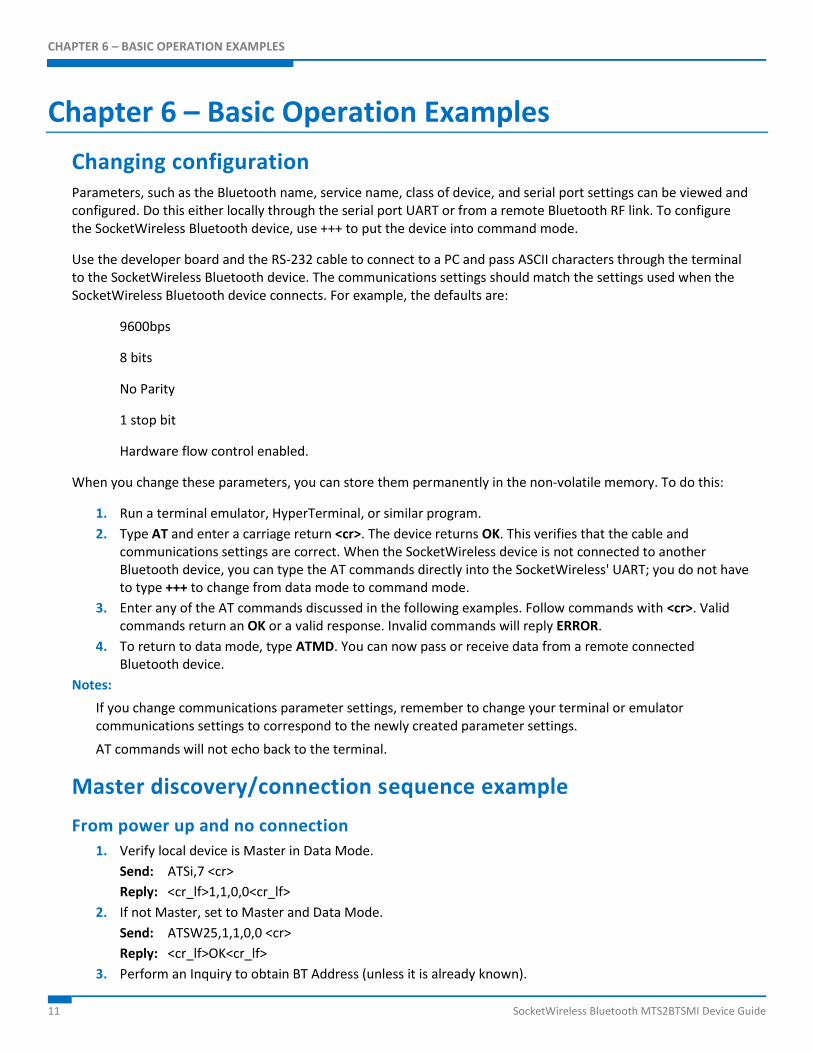
Chapter 6 – Basic Operation Examples
Changing configuration Parameters, such as the Bluetooth name, service name, class of device, and serial port settings can be viewed and configured. Do this either locally through the serial port UART or from a remote Bluetooth RF link. To configure the SocketWireless Bluetooth device, use +++ to put the device into command mode.
Use the developer board and the RS-232 cable to connect to a PC and pass ASCII characters through the terminal to the SocketWireless Bluetooth device. The communications settings should match the settings used when the SocketWireless Bluetooth device connects. For example, the defaults are:
9600bps
8 bits
No Parity
1 stop bit
Hardware flow control enabled.
When you change these parameters, you can store them permanently in the non-volatile memory. To do this:
1. Run a terminal emulator, HyperTerminal, or similar program.
2. Type AT and enter a carriage return <cr>. The device returns OK. This verifies that the cable and communications settings are correct. When the SocketWireless device is not connected to another Bluetooth device, you can type the AT commands directly into the SocketWireless' UART; you do not have to type +++ to change from data mode to command mode.
3. Enter any of the AT commands discussed in the following examples. Follow commands with <cr>. Valid commands return an OK or a valid response. Invalid commands will reply ERROR.
4. To return to data mode, type ATMD. You can now pass or receive data from a remote connected Bluetooth device.
Notes:
If you change communications parameter settings, remember to change your terminal or emulator communications settings to correspond to the newly created parameter settings.
AT commands will not echo back to the terminal.
Master discovery/connection sequence example
From power up and no connection
1. Verify local device is Master in Data Mode.
Send: ATSi,7 <cr>
Reply: <cr_lf>1,1,0,0<cr_lf>
2. If not Master, set to Master and Data Mode.
Send: ATSW25,1,1,0,0 <cr>
Reply: <cr_lf>OK<cr_lf>
3. Perform an Inquiry to obtain BT Address (unless it is already known).

CHAPTER 6 – BASIC OPERATION EXAMPLES
SocketWireless Bluetooth MTS2BTSMI Device Guide 12
Send: ATUCL<cr> // Clears radio state and places in Idle Mode
Reply: <cr_lf>OK<cr_lf>
Send: ATDI,1,00000000 {Class of Device}<cr> // Looks for only one Bluetooth device
Reply: <cr_lf>00A0961F2023,00000104,Socket Wireless<cr_lf>
<cr_lf>DONE<cr_lf>
4. Perform a Master Connect over SPP using the BT Address.
Send: ATDM, 00A0961F2023,1101<cr> // SPP connection
Reply: <cr_lf>CONNECT,00A0961F008F <cr_lf> // Returns Slave BT address radios is in Data Mode
5. Place radio into Fast Data Mode.
Send: ATMF<cr> // Places radio in Fast Data Mode
Reply: <cr_lf>OK<cr_lf>
6. Send Data.
Note:
When the Slave connects in Fast Data Mode (ATSW25/or issuing ATMF), all valid AT commands sent through the Slave’s UART will be interpreted and responded to by the Master radio as if it was the local Slave radio. In this configuration, you can obtain status from the Slave end and configure from the remote Master radio.
To exit data mode and check status
1. Delay at least 50 milliseconds; this could be less or more.
2. Get into command Mode.
Send: +++<cr> // Default escape sequence of characters
Reply: <cr_lf>OK<cr_lf>
3. Check status
Send: AT<cr>
Reply: <cr_lf>OK<cr_lf>
4. Send any AT Command example:
Send: ATSI,0<cr>
Reply: <cr_lf>SocketWireless AT<cr_lf>
Slave command sequence example
From power up
1. Check and verify communication to Slave. Sent: AT<cr>
Reply: <cr_lf>OK<cr_lf>
2. Get information on Slave Bluetooth address. Sent: ATSi,1<cr>
Reply: 12-digit address
<cr_lf>OK<cr_lf>
3. Set Slave to automatically connect in Fast Data Mode on Bluetooth connection. Sent: ATSW25,0,0,0,0 <cr>
Reply: <cr_lf>OK<cr_lf>
4. Either cycle power or send ATURST.

CHAPTER 6 – BASIC OPERATION EXAMPLES
13 SocketWireless Bluetooth MTS2BTSMI Device Guide
Note:
This command sequence assumes the radio is in factory default in which it automatically comes up and is
connectable as a Slave from a Master request.
Using AT commands to disable flow control
Protocol Change:
For Bluetooth protocol V2.0, the circuit board I/O pin 7 now controls flow control.
Previous Protocol V1.2 New Protocol V2.0 ATSW22,3,x,x ATSW22,7,x,x ATSW23,3,x,x ATSW23,7,x,x
Disabling Flow Control Using Protocol V.2.0
Using a terminal screen with flow control enabled, issue commands to turn off flow control.
Sent: ATSW22,7,1,0 <cr> // Set PIO7 as output and do not store in flash
Reply: OK<cr_lf>
Sent: ATSW23,7,1,0<cr> // Set PIO7 output high and do not store in flash
Reply: OK<cr_lf>
To store the setting in flash:
Sent: ATSW22,7,1,1<cr> // Set PIO7 as output and store in flash
Reply: OK<cr_lf>
Sent: ATSW23,7,1,1<cr> // Set PIO7 output high and store in flash
Reply: OK<cr_lf>
Now you can communicate with the Bluetooth device with flow control turned off.
Other examples See the Bluetooth AT Commands Reference Guide for other examples:
Multipoint example using the SocketWireless MTS2BTSMI or the Bluetooth Adapter MT2BTA – One Slave and Four Master Devices.
Multipoint example using the SocketWireless MTS2BTSMI or the Bluetooth Adapter MT2BTA – One Master and Four Slave Devices.
Repeater example using the SocketWireless MTS2BTSMI or the Bluetooth Adapter MT2BTA.