SO rH CHEMISTRY OF IIALIDE WINDOW GROWTH - Defense ... · MMMMMBI SO rH AFML-TR-75 217^ 6 CHEMISTRY...
76
SO rH AFML-TR-75 217^ 6 CHEMISTRY OF IIALIDE WINDOW GROWTH Hughes Research Laboratories 3011 Malibu Canyon Road ^ Malibu. CA 90265 February 1976 Technical Report AFML-TR-75-217 Final Technical Report for period 1 April 1974 through 30 September 1975 APPROVED FOR PUBLIC RELEASE; DISTRIBUTION UNLIMITED Sponsored by Defense Advanced Research Projects Agency! 1400 Wilson Boulevard 2 19T6 Arlington, VA 22209 ^ U M ;.:,,üUL^LHJ A Air Force Materials Laboratory Air Force Wright Aeronautical Laboratories Air Force Systems Command Wright-Patterson AFB, OH 45433
Transcript of SO rH CHEMISTRY OF IIALIDE WINDOW GROWTH - Defense ... · MMMMMBI SO rH AFML-TR-75 217^ 6 CHEMISTRY...

■MMMMMBI ■
SO rH
AFML-TR-75 217^ 6
CHEMISTRY OF IIALIDE WINDOW GROWTH
Hughes Research Laboratories
3011 Malibu Canyon Road ^ Malibu. CA 90265
February 1976
Technical Report AFML-TR-75-217
Final Technical Report for period
1 April 1974 through 30 September 1975
APPROVED FOR PUBLIC RELEASE; DISTRIBUTION UNLIMITED
Sponsored by
Defense Advanced Research Projects Agency!
1400 Wilson Boulevard 2 19T6
Arlington, VA 22209 ^ U M ;.:,,üUL^LHJ A
Air Force Materials Laboratory Air Force Wright Aeronautical Laboratories
Air Force Systems Command
Wright-Patterson AFB, OH 45433
,i..ii^*käiiiiiSaviitht..

DISCLAIMER NOTICE
THIS DOCUMENT IS THE BEST
QUALITY AVAILABLE.
COPY FURNISHED CONTAINED
A SIGNIFICANT NUMBER OF
PAGES WHICH DO NOT
REPRODUCE LEGIBLY.

DARPA Order Number
Program Code Number-
Contractor
Effective Date of Contract
Contract Expiration Date
Amount of Contract
Contract Number
Principal Investigator and Telephone Number
Title of Work
2612
4D12
Hughes Research Laboratories
1 April 1974
30 September 197 5
$243,936.00
F33615-74-C-5115
R. C. Pa-stor (213) 456-6411
Chemistry of Halide Window Growth
The views and conclusions contained in this document are those of the authors and should not be interpreted as necessarily representing the official policies, either expressed or implied, of the Advanced Research Projects Agency or the U.S. Government.

NOTICE
When Government drawings, specifications, or other data are used for any ourpose other than in connection with a definitely related Government procurement operation, the United States Government thereby incurs no responsibility nor any obligation whatsoever; and the fact that the government may have formulated, furnished, or in any way supplied the said drawings, specifications, or other data, is not to be regarded by implication or otherwise as In any manner licensing the holder or any other person or corporation, or conveying any rights or permission to manufacture, use, or sell a-iy patented invention that may in any way be related thereto.
This report has been reviewed by the Information Office (01) and is releasable to the National Technical Information Service (NTIS). At NTIS, it will be available to the general public, including foreign nations.
This Technical Report has been reviewed and is approved.
ß.GJ* /ohn R. Renter, Project Engineer Laser and Optical Materials Branch Electromagnetic Materials Division Air Force Materials Laboratory
u. (\
kv ^ iißXMAM \\j Lj ^ ^^a
William G. D. Frederick, Chief Laser and Optical Materials Branch Electromagnetic Materials Division Air Force Materials Laboratort
Copies of this report should not be returned unless return is required by security considerations, contractual obligations, or notice on a specific document.

UNCLASSIFIED SECURITY CL*SS(FICATION OF THIS PAGE (Whtn D.l« Enitrrd)
EPORT DOCUMENTATION PAGE
CHEMISTRY OF JiALIDE WINDOW GROWTH^ ^
READ INSTRUCTIONS BEFORE COMPLETING FORM
7. AUTHORf«;
R.C./Pastor« » H. V.^Winston .
9. PERFORMING ORGANIZATION NAME AND ADDRESS
Hughes Research Laboratories 3011 Malibu Canyon Road Malibu. CA 90265
Final Tech. Rpf 1 Apr 1974 - 30 Sep 1975
6. PERFORMING ORG. REPORT NUMBER
CONTRACT OR GRANT NUMBERf.-O
F33615-74-C-5115 '/
10 PROGRAM ELEMENT. PROJECT, TASK AREA 4 WORK UNIT NUMBERS
Py eg I'a Hi Cade11 IDILü
//ARPA Order»2612 U. CONTROLLING OFFICE NAME AND ADDRESS
Defense Advanced Research Projects Agenc 1400 Wilson Boulevard Arlington. VA 22209
14, MONITORING AGENCY NAME I ADDRESSf,! .„((.--enl (mm C.mttMtln» Olllr»)
United States Air Force Air Force Systems Command Wright-Patterson AFB, OH 45433
«^ uiinnul.LU'll. ...~
' iFebOTfa»7 6 / muw UM P wuta '-<
:5 SECURITY CLASS, fo/ (his reporr;
UNCLASSIFIED is» D'F^C'LVSSTFTC'AT
SCHEDULE
16. DISTRIBUTION STATEMENT (üi rh/.s Repo"
Approved for public release; distribution unlimited
17, DISTRIBUTION STAT EMENT (ol the abslrhct entered in ni.'^k ,0, ,1 dllUtenl Irom Rfport)
18. SUPPLEMENTARY NOTES
19. KEY WORDS (ConUnu, on ZZ7Z fäe il nectary W iSZrtfi bv üt^k wmb*,}
Laser Windows, Reactive Atmosphere Process, Nascent Halogen, Crystal Growth, Low Absorption, Bromides, Chlorides, and Fluorides.
20 ABSTRACT (Con.lnue on TZXZ riS H necessary and Id^tlf, by block „umfceO
^ClilmMB itmrHnfilflin chemistry of reactive atmosphere processing (RAP) for the growth of crystals of chlorides, bromides, and halides^ The purity and freedom from extrinsic absorption obtained by RAP are important in the application of halides as optical elements in high power lasers, ^ ^
| U3 to stu </1 fV
Qjj FORM l^J EDITION OF I NOV 65 IS OBSOLETE TTNCLASSIFIED SECURITY CLASSIFICATION OF THIS PAGE (When Da.a Entered)
//X (fOO /* {-

f
UNCLASSIFIED
VWiCvOVnC'tV
SECURITY CLASSIFICATION OF THIS PAGEf»?ien Data Entered)
The prototype of RAP is CC1 in the growth i^ KCI; it react- directly with water to scavenge out all traces of this contaminant and pyrolyzes with the formation oL-nascent halogen to react rapidly with hydroxide ions in the melt, wrr approach with the bromides and fluorides has been to seek RAP agents which simulate the behavior of CCl. with KCl.^
^-—-1^-" \^u?' ^On the basis of its hydrolysis behavior, we ag-l^ctcd ClrUBr^/He .a-s".-A
the RAP agent for KBr. This has consistently yielded material with a 10. 6 t^P bulk absorption coefficient O£.2-K l&^-^cm"^, an order of magnitude below that of non-RAP KBr. Further improvement is possible»..there are indications of incomplete hydroxide ion removal such as partial sticking of the crystal ingot to the silica crucible and fogging of crystal surfaces on exposure to the environment. One calorimetry run gave a bulk absorption coefficient as low as 2 x 10 em' j^Itl addition, w"ejiave..found that the minimum-melting solid solution of NaBr and KBr prepared under RAP conditions does not retain phase homogeneity below the melting point, making it impossible to grow single crystals of this material.
We directed ourVork on KCI toward problems associated with the scale up of RAP to produce KCI crystals of greater than 10-cm diam- eter^ The longer processing time required for larger crystals results
^--irTan accumulation of C and CU from the pyrolysis of CCl4. Deposited carbon can be included in the final crystal, and the buildup of Cl-, leads to corrosion of the growth apparatus. We have employed admix- tures of CO2 and variations in the concentration of CCl4 in attempts to control these problems. The results provide a basis for further actual large-scale crystal growth experiments.
Hydrogen fluoride, previously used alone as a RAP agent for fluoride crystal growth.J^ fast acting but does not achieve a low RAP index, P(H?0)/P(HF)/We hav-»-&upulemontod it with a fluorocarbon'. awriaJ^ j^hiuyj.«! improved transparency with CF4 admixtures^"^Car^orTTetra fluoride is the actual agent present when CTF, from the decomposition of Teflon is used in RAP, since C2F4 breaks down into CF4 at temperatures below the melting point J of the alkaline earth fluorides. Thus, teflon may be regarded as an inexpensive source of CF, for RAP. 4
CM-
.<*,.-* J^rt
UNCLASSIFIED SECURITY CLAbSiriCATION OF THIS PAGE'lVhcn Di-tii Fnrrred)
ii

PREFACE
This Final report describes work performed by personnel of
the Hughes Research Laboratories Division of Hughes Aircraft Company.
3011 Malibu Canyon Road, Malibu. California 90265, during the period
1 April 1974 through 30 September 1975, under Contract F33615-74-C-
5115. Project Number 2612. The program was initially monitored by
Dr G. E. Kuhl of the Air Force Materials Laboratory: the present
monitor is Mr. John R. Fenter (AFML/LPO). At Hughes, the
Principal Investigator is Dr. Ricardo C. Pastor; the Program Manager
is Dr. H.V. Winston. The program is devoted to a study of the chemistry related to
the reactive atmospheric process (RAP) technique for the crystal
growth of low-absorption high-purity metal halides important for high-
power laser windows. Mr. K. Arita. Mr. M. Robinson. Mr. A.C.
Pastor and Mr. M. Aaronson have participated in the chemical and
crystal growth investigations, and optical measurements have been per-
formed by Dr. Susan Allen, Mr. Paul Coker, and Mr. M. Aaronson.
The report has been prepared by Dr. Pastor with the assistance
of Dr. Winston and was submitted for approval 15 October 1975.
' '
■
■ ■ , :' 3
m
k

TABLE OF CONTENTS
SECTION
I
II
III
IV
INTRODUCTION
BACKGROUND
RAP CHEMISTRY AND CRYSTAL GROWTH
Task A
Task B
Task C
Bromides
PAGE
1
3
7
7
Chlorides (KC1) • • • 12
13
23
Fluorides (MF2 and Solid Solutions . . .
EVALUATION
Task A: Bromide (KBr) 23
Task B: Chloride (KC1)
Task C: Fluoride (MF2 and Solid Solutions) . . . 29
CONCLUSIONS AND RECOMMENDATIONS 37
APPENDIX A - Crystal Growth in a Reactive Atmosphere • ^
APPENDIX B - Crystal Growth of KBr in a Reactive Atmosphere 47
APPENDIX C - Crystal Growth of KC1 in a Reactive Atmosphere 53
APPENDIX D - Crystal Growth of Alkaline Earth Fluorides in a Reactive Atmosphere
APPENDIX E
REFERENCES
Approach to Equilibrium in the Dissociation of Xg
59
67
71
r PRECEDim PAGE BLANK-WOT FIWED

T ■^«iWW^flWWW1 i»*»'.«»W»»':
LIST OF ILLUSTRATIONS
FIGURE PAGE
1 Pyrolysis of CBr./He and CCl./He at 8000C . . 8
2 Single-crystal ingots of the minimum- melting solid solutions of the alkaline earth fluorides 17
3 Temperature dependence of the decay constant (k) for the depolymerization of TFE under various atmospheres 20
4 Infrared transmission of KBr single crystals 24
5 Infrared transmission of a 12.2 cm long KC1 single-crystal ingot grow?, in CC14/C02 " 27
6 Infrared spectrum of single crystal BaF2 grown in HF/He 30
7 Infrared spectrum of single crystal SrF2 33
8 Infrared spectra of single-crystal, minimum-melting, solid solutions of the alakaline-earth fluorides 34
A-l Schematic of pyrolysis apparatus 42
A-2 Sublimation of CBr« versus temperature 44
A-3 A 10-cm diameter single-crystal KC1 grown by RAP-Bridgmaq with CCI4 in He at a flow of ^0.5 cm3/s 45
B-l RAP grown single crystal KBr 51
C-l Bridgman KC1 ingots grown under CCl4/He and CC14/C02 56
D-l Crystal growth of MF2 61
0-2 Transmission of RAP Crystals 62
vii
PRECEDING PAGE BLANK-NCT FILLED

I. INTRODUCTION
This program is a study of reactive atmosphere processing
(RAP) chemistry, applied to metal halide crystal growth. The ultimate
application of the crystals is as optical windows and components for
10 |i.m (chlorides and bromides) and 2 to 6 |JLm (fluorides). The object
of the study is to establish the thermal decomposition (pyrolysis) behav-
ior of candidate RAP agents and then to choose the RAP agent with the
thermal behavior best suited to the processing and crystal growth re-
nuirements of a given metal halide. The study is divided into three
tasks: Task A, bromides; Task B, chlorides; and Task C, fluorides.
Our general approach is to find compounds of the appropriate
halogen which behave as CCK does with KCl; good RAP agents should
react directly with water to scavenge all traces of this universal con-
taminant as well as pyrolyze with the formation of nascent halogen to
react rapidly with hvdroxide ions in the melt. Additional requirements
are freedom from crucible corrosion and the possibility of complete
removal of pyrolysis products that might interfere with crystal growth.
The objective in Task A is to develop a RAP growth procedure
for KBr and its congruent-melting solution with NaBr. These materi-
als are of interest for window use in the 10 faxn region. The RAP
growth recipes are based on the results of pyrolysis studies of CBr^
and its derivatives.
The objective in Task B is to optimize the RAP chemistry and
growth procedure for the scaled-up growth of larger crystals of KCl
(210 cm diameter), another 10 |JLm window material. Although CCl.
works as a RAP agent the larger processing time necessary in scaled-
up growth leads to various problems arising from the accumulation
of C and Cl? from the pyrolysis of CCl.. The deposited carbon may be
a contributing factor to significant deviations of the ingot from mono-
crystallinity and, not infrequently, reduces the utilizable fraction. The
smaller carbon particles remain suspended in the melt and become in-
clusions in the crystal which lower the 10.6 |JLm laser-damage threshold
of the crystal. Excessive buildup of Cl- limits the lifetime of the
growth apparatus.
1

11 ■
objective in Task C is to improve the RAP recipe for the
growth o. ...kaline earth fluorides and its solid solutions, i.e. , mixed
cation fluorides. These materials are of interest for window use in
the 2 to 6 H-m region. In the past, RAP growth was carried out with HF,
which we now realize is an inadequate RAP agent. Because of outgas,
the RAP-index. P(H20)/P(HF), during growth is three orders of mag-
nitude larger than the H20-content of the HF gas in the cylinder (see
Appendix D). Consequently an additional vapor-phase reactant is
needed to react with H20, preferably, to convert H20 to HF.
w —, —-5
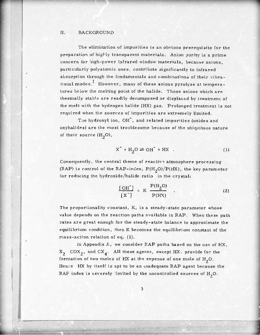
II. BACKGROUND
The elimination of impurities is an obvious prerequisite for the
preparation of highly transparent materials. Anion purity is a prime
concern for high-power infrared window materials, because anions,
particularly polyatomic ones, contribute significantly to infrared
absorption through the fundamentals and combinations of their vibra-
tional modes. However, many of these anions pyrolyze at tempera-
tures below the melting point of the halide. Those anions which are
thermally stable are readily decomposed or displaced by treatment of
the melt with the hydrogen halide (HX) gas. Prolonged treatment is not
required when the sources of impurities are extremely limited.
The hydroxyl ion, OH , and related impurities (oxides and
oxyhalides) are the most troublesome because of the ubiquitous nature
of their source (H_0),
X + H20 3Ä OH" + HX . (i:
Consequently, the central theme of reactive atmosphere processing
(RAP) is control of the RAP-inclex, P(H20)/P(HX), the key parameter
for reducing the hydroxide/halide ratio in the crystal:
Loio = K ^2°) [X"] P(HX)
(2)
The proportionality constant, K, is a steady-state parameter whose
value depends on the reaction paths available in RAP. When these path
rates are great enough for the steady-state balance to approximate the
equilibrium condition, then K becomes the equilibrium constant of the
mass-action relation of eq. (1),
In Appendix A, we consider RAP paths based on the use of HX,
X- COX», and CX.. All these agents, except HX. provide for the
formation of two moles of HX at the expense of one mole of HO.
Hence HX by itself is apt to be an inadequate RAP agent because the
RAP index is severely "imited by the uncontrolled sources of H_0.

Aside from the RAP-index consideration, which shows that all
HX are inadequate RAF agents, HF is the poorest agent in the HX
group for RAP growth by eq. (1). In contrast to HCl, HBr, and HI, the
free energy of formation (AG) of HF is lower than that of H?0. With
increasing T, AG(HF) decreases while AG(H O) increases. In the
alkaline-earth halides, the fluorides have the lowest AG and the highest
melting point. For example, the equilibrium constants for eq. (I) of
the calcium halides at their respective melting points are CaF^, K -
0. 055; CaCl2, K = 0. 0034; CaBr2, K ^ 0. 0052; and Calg, K = 0. 018.
A higher value of K in eq. (1) means a higher degree of hydrolysis. The 2
calculation of K is given in detail in Interim Report 1.
The basis for selecting the reactions of X-, COX?, and CX . was
the thermodynamic value of the RAP index. This calculation of the
RAP irdex deals only with homogeneous RAP, i.e. , the gas phase,
and appears to be a good first approximation at the higher operating
temperatures where reaction rates are large. At the growth tempera-
ture, the rates tending to equilibrate the condensed phases (melt and
crystal) with the vapor are much faster than the growth rate. This
coupling of rates in the heterogeneous system enables the gas phase to
act as the impurity sink, hence the utility of the RAP index.
Appendix A provides a comparison of the KAP-index for
chlorides, i.e. , Cl2, COCl2, and CCl4, from 600 to l200OK. Both
COCl^ and CCl. are far superior to Cl? as RAP agents. Carbon tetra-
chloride is preferred to COCl^ because it is less toxic and earuer to
handle.
Another advantage to the use of CX . as the RAP agent is the
pyrolytic generation of the nascent halogen (X). All the nascent halo-
gens, i. e. , X = F, Cl, Br, and I, have a higher electron affinity than
the OH radical and, therefore, will be potent agents for the displace-
ment of OH in the melt (see Appendix A).
However, pyrolysis temperature depends upon the vibration
frequency and dissociation energy of the C-X bond. If pyrolysis occurs
at a temperature far below the me lung point of the halide, the recipe
is impractical. The nascent halogen is rapidly converted to the

molecular (diatomic) form which, except for F,, is ineffective foi RAP
growth. At the uallde meltin- point, although the equilibrium approach
to dissociation X — 2 X. in fast, the extent of dissociation is small
(see Appendix E). Thus, at 100öOK the time required to reach the half-
point of equilibrium and the degree of dissociation are as follows:
F , 3. 5 x 10"7 sec and 4. 3%; Cl^, 7. 1 x 10"5 sec, 0. 035%; Br2, 2. 2 x
10"6 sec, 0,23%; and I,, 2.7 x 10'7 sec, 2.8%.
From the preceding discussion, it is clear that the CX^ pyrolysis
path useful to RAP is
CX4 — 1/2 C2X6 + X . (3)
The undesi.red path is
CX. — C + 2X, 4 2
(4)
These two pa.hs compete and the dominance of one over the other depends
on temperature. This competition is summarized in the following total
reaction
CX. — fC + 4
1 - f r ^ . 3f + I x —T" C2X6 + ~^^ X2
(5)
where f - 0 is eq. (3) and f = 1 is eq. (4). The object in RAP chemistry
is to attain an f value close to zero at the melting point of the metal halide
in question. The schematic of the pyrolysis apparatus and the procedure
followed to determine f versus temperature is given in Appendix A.
■ J

III. RAP CHEMISTRY AND CRYSTAL GROWTH
Task A; Bromides
Pyrolysid studies with He as the carrier gas showed that the f
value of C.Br4/He was very dote to unity at 700OC (see Appendix B).
Hence, at the melting point of KBr (mp s 7 30OC). the halogen would be
in the molecular foim (Br,) accompanied by a heavy deposit of carbon.
This striking difference in pyrolysis behavior between CBr4/He and
CCl./He is shown in Fig. I. To provide a qxück test for the suitability of RAP agents, the
pyrolysis chamber was replaced with a horizontal silica tube. Silica
boats loaded with KBr powder were melted under a flow of 1 cm /sec
of RAP agent/He. At the given flow, the pyrolysis residence time was
200 sec. With this test apparatus, it was established that neither CBr4/
He nor CHBr /He was suitable for RAP growth of KBr.
The C-Br bond dissociation energy (D) increases with the extent
of replacement of bromine by a more strongly covalent-bonded substi-
tuent: CBr4, 49; CHBr3, 56; CH^, 63: CF^r, 65; and CH3Br. 67
(unit of D in kcal). 3 The C-Br dissociation has been shown to be charac-
terized by
k = vexp(-D/RT) , (6)
where v and D are the C-Br vibration frequency and dissociation energy,
respectively.4 The value of v =1.75x10 s' (Ref. 5). At the RAP growth temperature, pyrolysis should be constrained
to 0 < k < 1. At k = 1, the agent would pyrolyze completely in the vapor
phase; the halogen reaching the melt would be in the molecular form.
From eq. (6) at 730OC (KBr mp), k < 1 if D > 61 kcal and this would
explain why CBr4 and CHBr3 were inadequate. The two RAP agents which gave encouraging results in experi-
ments on the melting of KBr were CH^r,, and CF^r. Pyrolysis
measurements showed that CH^r., was a poorer source of nascent
bromine than CF3Br (see Appendix B). Observation of the nonwetting
„mum
PBECEDim PA(5£ BLANK-NOT FIMSD

CARRIER GAS: He SOURCE TEMPERATURE : 240C
PYROLYSIS APPARATUS
PYROLYSIS OF CBr4 AT 800oC/20 h
INPUT =2.55xl0"8
MOLE CBr4/cm3
PYROLYSIS OF CC AT 800°C/20h
INPUT = 5.40xl0"6
MOLE CC^/cm3
Figure 1. Pyrolysis of CBr4/He and CCl4/He at 800OC.
_. .
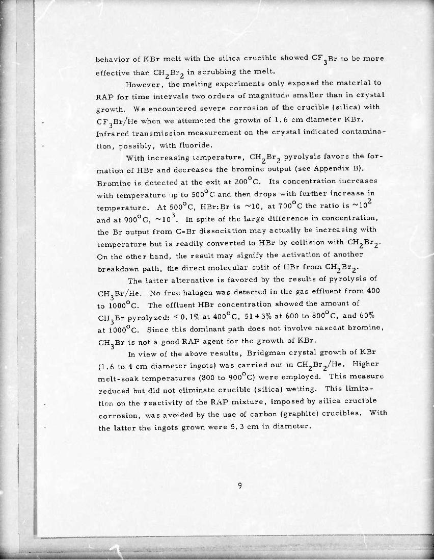
behavior of KBr melt with the silica crucible showed CF Br to be more
effective than CH2Br2 in scrubbing the melt.
However, the melting experiments only exposed the material to
RAP for time intervals two orders of magnitude smaller than in crystal
growth. We encountered severe corrosion of the crucible (silica) with
CF. Br/He when we attempted the growth of 1. 6 cm diameter KBr.
Infrared transmission measurement on the crystal indicated contamina-
tion, possibly, with fluoride. With increasing temperature, CH Br pyrolysis favors the for-
mation of HBr and decreases the bromine output (see Appendix B).
Bromine is detected at the exit at 200OC. Its concentration increases
with temperature up to 500OC; and then drops with further increase in
temperature. At 500OC, HBr:Br is ~10, at 700OC the ratio is ~10
and at 900OC, ~10 . In spite of the large difference in concentration,
the Br output from C-Br dissociation may actually be increasing with
temperature but is readily converted to HBr by collision with CH2Br2.
On the other hand, the result may signify the activation of another
breakdown path, the direct molecular split of HBr from CH2Br2.
The latter alternative is favored by the results of pyrolysis of
CH Br/He. No free halogen was detected in the gas effluent from 400
to 1000oC. The effluent HBr concentration showed the amount of
CH Br pyrolyzed: < 0. 1% at 400OC, 51 ± 3% at 600 to 800OC, and 60%
at 1000OC. Since this dominant path does not involve nascent bromine,
CH Br is not a good RAP agent for the growth of KBr.
In view of the above results, Bridgman crystal growth of KBr
(1.6 to 4 cm diameter ingots) was carried out in CH2Br2/He. Higher
melt-soak temperatures (800 to 900OC) were employed. This measure
reduced but did not eliminate crucible (silica) westing. This limita-
tion on the reactivity of the RAP mixture, imposed by silica crucible
corrosion, was avoided by the use of carbon (graphite) crucibles. With
the latter the ingots grown were 5. 3 cm in diameter.

Various NaBr-KBr mixtures, in a concentration range
straddling the minimum-melting composition, were melted in conical
crucibles under CF Br/He. After a few hours soak, followed by a slow
cool under RAP, the specimens were examined with the DuPont 900
Thermal Analyzer and characterized by Knoop hardness measurement
and x-ray powder diffraction.
Table I shows the results of the DTA and hardness measure-
ments. DTA measurement of the freezing and melting of the mixtures
showed a solid solution with a minimum. The observed minimum melt-
ing temperature under RAP is 62Ü0C at 48 mol% KBr while the litera-
ture gives 6440C and 53 mol% KBr, In spite of this difference, our
melting point determinations for NaBr and KBr showed no difference
between the untreated and the RAP-treated material. Our mean value
for the melting point of NaBr disagrees with certain literature values 7
(see footnote (b) of Table I) and Wicks and Block, who assign a
melting point of 7470C, but agrees with the more recent assignment Q
by Stull and Prophet,
If the solid-solution phase persisted through cooldown, the
Knoop hardness value would exhibit a broad maximum at the minimum
melting composition. The third column of Table 1 shows that this is
not the case. The hardness values shown were limited by the texture
of the material, which was very turbid, suggesting the separation
(precipitation) of other solid phases.
To test the latter hypothesis, we examined small ingots of
the frozen mixture by x rays. The ingots were ground to provide a
1 cm flat area for use in the x-ray analysis. Diffraction patterns
were made on the Norelco diffractometer with filtered CuKa radiation.
The patterns obtained from the ingots had intensity ratios for NaBr
and KBr which were proportional to the ratios derived from the start-
ing compositions, i.e, , the material behaved like a mechanical mixture
of NaBr and KBr, The position of the lines did not shift, which also
indicates that there was very little solid solubility of one component in
the other.
10
.aaaaa^Bia-m»""..—

TABLE 1. MELTING POINT AND KNOOP HARDNESS OF NaBr-KBr MIXTURES
M Die % KBr Melting Point,
OC Knoop Hardness,
kg / mm^
0 737 ±2(b) 7 to 8(C)
25 Jd) 3.4 to 5. 8
40 629 0.2 to 0. 3
45 621 0. 3 to 0. 4
50 621 0. 4 to 0. 6
55 629 0. 5 to 0. 7
60 63 5 1. 5 to 3.2
75 Jd) Je)
100 732.2^ 9. 9 to 10.7(f)
(a) Measured with a 15 g load unless specified otherwise.
(b) The range covers that obtained by direct melting of the reagent-grade powder and that obtained from the same material by RAP growth: NaBr in CUBr3/He and KBr in CH2Br2/He. The literature values are 7 550C for NaBr and 730OC for KBr; taken from Handbook of Chemistry and Physics, edited by R. C, Weast, 49th Edition (The Chemical Rubber Co., 1968-1969).
(c) Measurement made with 15; 25, and 50 g loads.
(d) Melting point not determined.
(e) Surface texture too crumbly to warrant a hardness measurement
(f) 2 . A Knoop hardness of 7. 0 kg/mm is reported for the RAP-
untreated KBr on page 13 of Harshaw Optical Crystals, (The Harshaw Chemical Company, 1967).
11
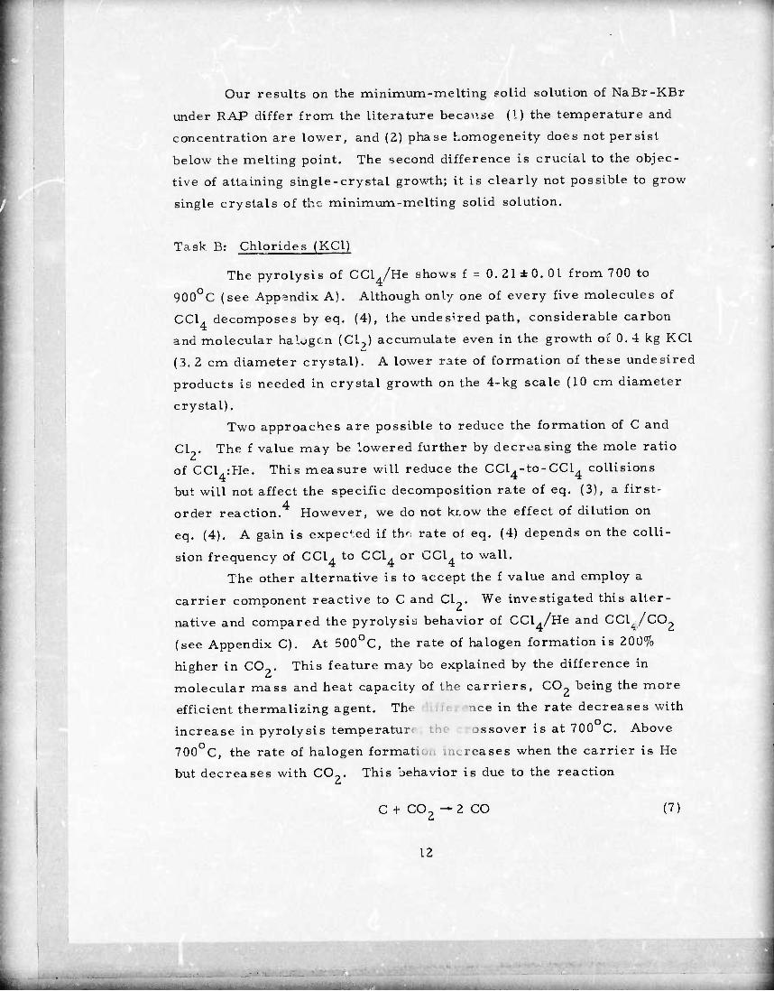
Our results on the minimum-melting golid solution of NaBr-KBr
under RAP differ from the literature because (I) the temperature and
concentration are lower, and (2) phase homogeneity does not persist
below the melting point. The second difference is crucial to the objec-
tive of attaining single-crystal growth; it is clearly not possible to grow
single crystals of the minimum-melting solid solution.
Task B: Chlorides (KCl)
The pyrolysis of CClJUe shows f = 0. 21 ± 0. 01 from 700 to
900OC (see Appendix A). Although only one of every five molecules of
CCl4 decomposes by eq, (4), the undesired path, considerable carbon
and molecular halogen (Cl,) accumulate even in the growth of 0.4 kg KCl
(3. 2 cm diameter crystal). A lower rate of formation of these undesired
products is needed in crystal growth on the 4-kg scale (10 cm diameter
crystal). Two approaches are possible to reduce the formation of C and
Cl9. The f value may be lowered further by decreasing the mole ratio
of CCl.:He. This measure will reduce the CCl4-to-CCl4 collisions
but will not affect the specific decomposition rate of eq. (3), a first-
order reaction. However, we do not kr.ow the effect of dilution on
eq, (4), A gain is expected if th' rate ol eq, (4) depends on the colli-
sion frequency of CCl. to CC1. or CCl. to wall.
The other alternative is to accept the f value and employ a
carrier component reactive to C and Cl . We investigated this alter-
native and compared the pyrolysis behavior of CCl ./He and CCl^,/C02
(see Appendix C). At 500OC, the rate of halogen formation is 200%
higher in CO . This feature may be explained by the difference in
molecular mass and heat capacity of the carriers, CO,, being the more
efficient thermalizing agent. The nee in the rate decreases with
increase in pyrolysis temperatur ossover is at 700 C. Above
700OC, the rate of halogen formatio., increases when the carrier is He
but decreases with CO-, This behavior is due to the reaction
C + C02 — 2 CO (7)
12

B
and the resulting CO tying up free chlorine,
CO + ci2 -* coci2 . (8)
The decrease in free halogen content of the exit gas is explained
by eq. (8), which is dependent on eq, (7). TJ assess the efficiency of
eq. (7), a 20-hou:" pyrolysis at 800 C was carried out. No a carbon de-
posit formed in the case of CClVCO-. This feature was reproduced
in crystal growth (see Appendix C, Fig. 1).
Window specimens, 10 cm in length, were fabricated from these
crystals. For both specimens, the infrared transmission (Beckman
IR 12) was flat at 94% transmission from 2, 5 to 12.5 |j.m with the knee
of the curve at 14. 5 jam. In the 10 jam region the differences are ^0. 5%
which indicates that the absorption coefficient at 10. 6 (J.m would differ
by <0.0005 cm between the two specimens. This difference could
be accounted for by surface fabrication.
The results of infrared transmission measurements are signifi-
cant to the objective of RAP growth, viz. , removal of anion impurities.
With CO_ as the carrier, the presence of O- and OH impurities in the
melt would have led to the formation of CO" and HCO- impurities,
respecti/ely: C02 + 0= — CO^ and C02 + OH" —HCO^.
In 10 cm length KC1, 100 ppm CO" would have shown absorp-
tion bands from 6.6 to 14.7 fim, while 0. 1 ppm HCO,, would have given 1 absorption bands from 3. 0 to 15. 9 fjm. It can be shown that the
HCO~/CO~ ratio depends on OH /0~ which, in turn, depends on H^O.
Hence, the results obtained indicate that the RAP procedure provided
a very low value of the RAP index.
Task C: Fluorides (MF and Solid Solutions)
In Section II we discussed the thermodynamic basis for HF
being the poorest HX RAP agent. However, among all the RAP agents,
HX reacts withO- and OH with the lowest energy barrier. It is the
only agent capable of efficient halide conversion at room temperature.
The product of the reaction, H-O, must be removed to achieve a higher
13

degree of conversion. Because of the uncontrolled sources of H_0 in
RAP growth, e.g. , outgas (see Section I), it is clear that a secondary
RAP agent is needed to lower the RAP index.
Many hydrolyzable fluoride gases can convert one mole of H_0
to two moles of HF, e. g, , BF.,, PF,., SF, , and CF.. We considered
CF, and other fluorocarbons because th se agents are less likely to
cause complicating side reactions in our carbon resistance growth
furnace.
We studied the reaction of CF, with H^O, using both 5 mol% CF,
in He and pure CF ., at a flow rate of 0. 4 cm /sec, in a graphite reac-
tion chamber,
CF . + 2H00 Sfi CO- + 4 HF . 4 2 2 (9)
The HF content of the effluent was chronometrically titrated by bubbling
through a standard NaHCO, solution, using bromcresol green as the
indicator.
Table 2 is a summary of the results. The first-row data are
for outgassed H_0 only. At 900 C and at an effluent flow of 0. 37 cm / - 8 3 sec, [HF] - 1. 06 x 10 mol/cm , The outgassing surface was 190
2 cm . The forward direction of eq. (9) is favored, as seen in the
equilibrium constant; K(1200OK) = 6.8 x 1027 and K(1500OK) s 1.9 x
10 (unit: atm ). Hence, since [CF4]>> [H_0] from outgas, we
assumed 100% conversion of outgas H-O to 2HF. This assumption leads -11 2 to an H-O-outgas flux of 1.0 « 10 mol/cm /sec, which agrees in
magnitude with the observed outgassing of the Astro furnace.
Table 2 shows that the degree of conversion of H-O to 2 HF
increases with temperature but, at a given temperature, is inversely
proportional to the ratio of [H-O] :[CF.]. Thus, at 900C)C, 100% con- 3 version is expected for [H?0]:[CF.] =1:10 . For the given dilution of
5 mol% CF. in He, it is seen that the conversion increases by a factor
of 3. 2 for a temperature increase of 100 C. Assuming a simple
Arrhenius dependence of the rate on temperature, a value of [H_0]:[CF,]
= 1:10 from 5 mol% CF. in He would be completely converted at temper-
atures equal to or greater than 1300 C. These results apply to a
14

residence time in the chamber of 500 sec, which is a factor of two to
four smaller than the cases of crystal growth.
We conclude from these studies in fluoride RAP that
1. To provide rapid RAP of the condensed phase, HF should be the primary agent.
2. To lower the RAP index, CF . can be used to convert H-O to 2HF. If the process tempera- ture is low, e.g. , 900 C, complete conver- sion can be approximated with [H_0] :[ CF,] = 1:10 . If the process temperature is high, e.g. , 1300 C, then complete conversion is realized at [H20]:[CF4] a 1:10.
TABLE 2, REACTION OF CF4 WITH H20 IN GRAPHITE
[H?0] 2a
I^T 10
fHFl 102 [HFl 102 4CF4J 10
2[H2Oj 10
900oC 1000oC 900oC 1000oC
(0.0) 0, 13 (100) (100)
2.6 0.06 0. 13 4. 3 9.6
12.0 0,05 0. 17 0.85 2.8
55.0 0.05 0. 16 0. 19 0. 59
aThe value of (0.0) refers to H-O from out- gassing of the apparatus, 12 to saturation of the gas at 0OC, and 55 to saturation at 250C. The gas was 5 mol% CF4 in He. The value oi 2,6 was obtained by saturation of pure CF. with H-O at 250C.
15

From the H-O outgas in the Astro furnace, we estimate that -3 the CF. mole fraction in the vapor phase sir uld be ilO . Two RAP
recipes were compared in the crystal growth study: [HF]»[HEj a 0.44:
0. 56 (RAP-1) and [HF]:[He]:[CF4] = 0. 44:0. 56:0. 0028 (RAP-2). All
Bridgman crystal irgots grown were 4.2 cm diameter.
Since MF~ was grov/n previously in RAP-1 we grew CaF-, SrF-,
and BaF? by RAP-2. The infrared transmission of 5 cm path of these
crystals (Beckman IR 12) showed improved transparency over their Q
respective counterparts grown by RAP-1 in an earlier study. However,
when the melt receives a longer soaking in RAP-1, the IR transparen-
cies by RAP-1 and RAP-2 look the same. In this case, the higher
sensitivity derived from optical calorimetry is needed to detect the
smaller difference in the absorption coefficient, e.g. , 0. 1%/cm.
Melting congruency experiments under HF/He showed that
Ca-Sr and Sr-Ba cation pairs produce homogeneous crystal specimens,
but Mg-Ca and Ca-Ba do not. The published phase diagrams of
MgF2-CaF? show a simple binary with one eutectic point. ' In
CaF^-SrF^ a continuous solid solution is reported with a shallow mini-
mum near 50 mol% SrF- and 1330 C. Similarly, in the case of 13 SrF^-BaF- with the shallow minimum at 19 wt. % Sr.
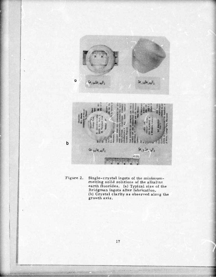
Single-crystal ingots of the minimum melting solid solutions,
Ca- c^Sr 4(1 F- and Sr .Ba» tiF-, were grown by RAP-1 and
RAP-2. Figure 2 shows the typical size of pieces fabricated from the
Bridgman ingot and the clarity as observer through the growth axis.
As detailed above, our approach to RAP growth is to use the
fast-acting HF as the primary agent and provide minor amounts of a
secondary agent, such as CF ., to achieve a low RAP-index. The RAP
agent recommended by workers in the USSR is C-F ., obtained from the 14 depolymerization of (C F.) or Teflon (also called PTFE).
Because AG^C-FJ > AG0(CF4), where AQ0 is the free energy
of formation, oxide conversion to the fluoride shows a larger lowering
in free energy with the use of CLF .,
0=(C) + 1/2 C2F4(g)-2F"(c)+ CO(g) , (10)
16
a
#
Ä .
CA.54SR.4fiF: 540K.46r2 SR.34ßA.66F
4 ,*J
■
CA 54Sf?.4fiF: 54^,46^2 ^.3^.^/2
cm
Figure 2. Single-crystal ingots of the minimum- melting solid solutions of the alkaline earth fluorides, (a) Typical size of the Bridgman ingots after fabrication, (b) Crystal clarity as observed along the growth axis.
17

and
0"(c) + 1/2 CFAg) -2F"(c) + l/2 CO {3) (ID
13
Oxide conversion to fluoride is also more thermodynamically favored
in CFA than in HF. However, we observe the reaction of CF4 to
0=(c) at 800OC to be many orders of magnitude smaller than the reac-
tion of HF to 0=(c) at 250C. We expect very low reaction rates also
in eq. (10). The C-F stretching mode absorbs strongly at v = 4 x 10
sec"1 (Ref. 5). From D = 121 kcal (Ref. 3), the specific rate constant 1
of the f = 0 path of eq. (5) at 1430OC (CaF2 mp) i. k < 0. 04 sec" ,
Comparison of eqs. (10) and (11) show that the free energy dif-
ference between the reactants is due to AG (C^^ > AG (CF4), and
between the products is due to AG0(CO)< l/2 AG0(C02). These two
differences are tied to the combustion reaction of CO to C02 and to
the dissociation,
C2F4: C + CF, (12)
Because AG0 (C^) > 0° (CFJ, the forward direction of eq. (12) is
favored: [CFJJEC^] is lO^at 600OC and 106 at 1430OC (CaF2 mp).
Kinetically.. uhc forward direction of eq. (12) may be expected
to have a realistic rate at temperatures well below the MiT, RAP work-
ing temperatures. From the bond strength and vibration frequency,
the rupture probability for -C a C- at 1430OC is greater than 1000%/sec.
In the pressure range 0. 2 to 1. 0 mm Hg of P(C2F4), decomposi-
tion occurred at 900OC on the surface of CaF2 powder. i Much lower
values of P(C_FJ must have been involved in the observation that
decomposition did not occur until 1200 C.
From our DTA characterization runs of PTFE we deduced that
after complete depolymerization at 550OC> (C2F4)n -* n C2F4, decomposi-
tion by eq. (12) at P(C2F4) m 10 atm occurred below 600OC. Using He
as a carrier gas with an average value of P(C2F4) = 40 mm, at a flow
of 0. 5 cm3/tec, a 2 min residence time through the pyrolysis chamber
(stainless steel coil) showed a GO elution spectra of [C2F4"|:[CF4]
« 1:103.
18

We therefore consider PTFE as an inexpensive source of
high-purity CF4, an expensive RAP agent. However, the breakdown
shown in eq. (12) must be avoided in the growth apparatus because of
the tendency of the carbon deposit to form a stable suspension in the
fluoride melt. This study consisted of two phases:
1. Depolvmerization kinetics of PTFE for the generation of C^F.
2. Production of CF4 from C^F.
In support of the first phase, we carried out first DTA (thermal)
characterization of the breakdown of PTFE. Our DTA thermogram
measuremputs (DuPont 900 Thermal Analyzer) show two eadotherms in
the heat-up of PTFE. Tht first endotherm corresponds to a reversible
process. It is a small peak which begins at 321 C and corresponds to 17 18 the melting point. ' The second endotherm corresponds to an
irreversible process, (C^F^ — n C^^. It is a large peak that begins
at 550OC. The next thermal characterization of virgin PTFE powder was
a series of isothermal runs under various atmospheres. The depoly-
merization rate was studied from 470 to 546 C using the DuPont 900
Thermal Analyzer thermogravimetric analysis (TGA) module. The
weight (W) of PTFE decayed with time (t) as a first-order process in
vacuum, Ar, CO,, or Ü-. At each temperature setting, the decay was
followed over a time interval greater than, or equal to, the half-life.
In these four cases, the linear fit to In W versus t, bv the method of
least squares, yielded a correlation coefficient with a deviation of 0. 1%,
from unity. Although a first-order decay in W at various temperature settings
was obtained for each atmosphere, the plot of In k versus reciprocal
temperature was not linear in the range 470 to 550 C. This is seen in
Fig 3 Our results in vacuum agree with the reported energy barrier o 19 of 83 kcal/mol in the range 360 to 510 C. Yet, at temperatures
greater than 530OC, it appears that the degradation path in vacuum has
a lower barrier. Only at pressures less than 5 mm does thermal degradation
(600OC) of PTFE yield 100% monomer (C2F4); at one atmosphere, the
19

vl r
Figure 3.
1.25 1.30 1.35
103/' 0K
Temperature dependence of the decay constant (k) for the depolymerization of TFE under various atmospheres:*, vacuunv.B, Ar; A, CO-', and ▼, 02'
20

products are C^ (16%), C^ (26%), and C^Fg (58%)." The product
variations are believed to be caused by reactions between C^F. and the
radical -CF_-.
Surface degradation of the solid by the radical is in harmony
with the following observations:
1. Linear dependence of In W on time
2, Change in energy barrier witli temperature (Fig. 3)
3. Slight effect of the nature of the atmosphere on 2 (Fig. 3).
4, Formation of C^F., C^F, , and C.FQ in Jie i <i 4 J b 4 o vapor phase.
The C-C bond is much weaker than the C-F bond. Hence, the first
observation indicates that the removal of units of -CF-- and -CF- -
CF-- occur at some energy barrier. There are two paths possible for
the latter species in the vapor phase,
■CF2 " CF2
^CF2 = CF2 (or C2F4)
^2 (-CF2-) . (13)
As vapor phase concentrations build up, side reactions follow.
-CF - CF,
CF2-
CF2-CF2
\/ CF,
(or C3F6) (14)
and
.CF2 - CF2. CF2-CF2
.CF2-CF2- CF2-CF2
21
(or C4F8) . (15)

Now, a -CF,- reacting with another -CF2- is already taken care of in
eq. (13). Ail these vapor phase reactions explain observation 4, but
do not affect the energy barrier for thermal degradation of the solid.
However, a -CF - attacking the surface to pull out a -CF--CF-- will » Z 2
lower the energy barrier and provide a basis for observations 2 and 3.
The second phase of this study, i.e. , the production of CF.
from C^F., still remains to be done.
22
k.

IV. EVALUATION
Task A: Bromide (KBr)
Two RAP agents, CH?Br2 and CF^Br, were employed in the
growth of KBr, with He as the carrier gas. The mixture CF^Br/He
was more effective than CH-,Br_/He for scrubbing the KBr melt but
was also more corrosive to the crucible (SiO-), Measurements with
the Beckrran IR 12 showed that KBr crystals grown in CH_Br /He
invariably yield a flat transmission from 2. 5 to 18 fxm (Fig. 4 (a)).
Those grown in CF-Br/He show extraneous absorption bands which
vary from one run to the next (Fig. 4(b)).
These variable absorptions probably were caused by impurities
leached out during corrosion of the crucible. However, the extraneous
band at 13 [Jim was always present with an absorption coefficient on the
order of 1%/cm. This band could be caused by F impurity arising
from the interaction of CF-Br with the crucible (SiO_). The extraneous
bands arising from the use of CF,Br/He were removed by CH Br_/He,
as shown in Fig. 4(c).
Bulk and surface absorptions at 10.6 |JLm of KBr grown in
CF,Br/He and CH?Br-/He were measured. The results are discussed
in Task B and summarized in Table 3.
Task B: Chloride (KC1)
Numerous oxyanion impurities contribute to the optical absorp-
tion at 10,6 |xm. The anion impurities that are of particular concern
to RAP growth of KCl i) CCl4/(He, CO ) are the carbonate (CO^) and
the bicarbonate (HCO"), The reactions leading to the formation of
these anions were discussed in Section III,
The bicarbonate/carbonate ratio is linked to the hydroxide/oxide
ratio.
HCO'(c) + O (c) == C03(c) + OH (c) . (16)
23

■
100
80 se
i6o CO
a z 40 < K
20 -
1 1 1 1 1 1 1 1 1 MM Mill 1 1 1 1
■I —
—
B98
-
KBr i=2.0cm
1 1 1 1 1 1 1 1 1 1 1 lllillll 1 V JL 6 7 8 9 10 12 14 16 20
WAVELENGTH, //m
30 50
a RAP grown in CH Br-ZHe,
100
a?
z
55 60 CO
I 40 I-
80=^
20
-n—r T 1 1—i—I I ' I I i mi I I I I I
j i 6 7 8
•WAVELENGTH, fim
9 10 12 14 16 20 30 50
b RAP grown in CF-Br/He,
Figure 4. Infrared transmission of KBr sirgle crystals.
24

100 1 1 1—I I I I I Mill II I I
80 Ml
9 60
z < cc p
40
20
J L
B96 KBr / = 3.3 cm
J | I I I I I Mill 6 7
WAVELENGTH, fim
8 9 10 14 16
c Melt soaked initially in CF-Br/He and firally in CH-Br/He.
Figure 4. Continued.
25

(18)
(19)
(20)
(21)
These anion impurities are subject to RAP because the hydroxide/oxide
ratio depends on the presence of H-O,
0=(c) + H20(g) sa 2 on'(c) . (17)
The preceding reactions illustrate the gettering effect of CO"
and HCO" through the lowering of the RAP index of the vapor phase.
Displacement reactions are also effected in the condensed phase by the
RAP agent, or its pyrolysis product, Cl^,:
CCl4(g) + 20=(c) -4Cl'(c) + C02(g)
CCl4(g) + 20H"(c) -2Cl'(c) + 2HCl(g) + C02(g)
Cl2(g) + CO^c) -2Cl"(c) + C02(g) +|o2(g) ,
Cl2(g) + HCO^c) » Cl» + C02(g) + HCl(g) + | 02(g)
Since these reactions are thermodynamically favored, it was expected
that the incorporation of CO" and HCO,, would be insignificant in RAP
with CCl,/(He, CO,,). This expectation was realized. Measurements
with the Beckman IR 12 showed an infrared transparency in KC1 grown
in CCl./CO- similar to that grown in CCl./He. An example is shown
in Fig. 5.
We attempted to separate the bulk (ß) and surface (cr) contribu-
tions :o the total absorption (a) at 10. 6 |J.m. We hoped to correlate
the value of (D to crystal quality and cr to the quality of the surface 21 finish. The ^^thod described by M. Hass was used with samples of
RAP KCl and KBr where the length: diameter ratio was equal to or
greater than 7. The results are presented in Table 3.
Some of the inconsistencies in the data can be attributed to the
presence of scattering centers in the bulk. Boules KBr-B72B,
KCI-B129 and KC1-B62 A and B were examined with a 6328 % He-Ne
laser beam along the cylindrical (growth) axis. The sides of the
fabricated priums were polished to allow observation of scattering per-
pendicular to the beam.
26

100
80
■?. o 60 (/I If)
2 CO Z 40 < tr
20
"i—r
5 6 7
WAVELENGTH, \m
I I I I I I Mill
B90 KC1
12.2 cm
J L 8 9
' ' I I I Mll\l 10 14 IS 20
Figure 5. Infrared transmission of a 12,2 cm long KCl single-crystal ingot (3 cm diameter) grown in CClVCO
27
1

i U W a ü S u
Q
U
o a a.
<l
0 i—i
H
0 PQ *t| H U <
p en Q
P PQ
W
EH
C 01 0^
«4-1 (fi
0) J3 be ►.
0) •
«■5 ^ ti 1 •si .p- X3
2 ^ E y E
in
0 4J
in ■ r-l •f* r~4 i—t
IS 0) ■d 3 M a
^4
1 1
E ni rt X S e rt O Ü i 0
0 ^
C in 0 "3 M 0
U 0) 1« 0 (u 1 1
o o U rt ,£5 2 D' X In a! rfl in
1—1 1—I
+J QJ +J 4-> u a U X X
« E T) <U 0 0; in
<U * c 0)
^H _ "V a (SJ O
i s 5 m ■w in J3 IJJ
0 ■*-> 4->
0 „ ■5«« M M
"o a
a u
II |1
-a o o o QJ CO *
0 XI o O o
n) u o O o
-a o , 1 n
A (Vl m
(M in •
0
OH
O O
m n in
-1 o o 1 o i
o ■—i o / /
o / ■/ /
r- o ^-( X
Is - •H in r~ r- o
3 u (VJ ^3 ro -H «*< ^ ^
4-1 un in «0 in o o
C E (U u
f"! ro .—i
oo o * 0)
IE in
rM (M IT)
ja
■* Tt ■* CQ CQ in
tJ « on U
Ü u u
U u
33 u u
X u
SS
u
< ffl a~ PQ < oo o
0 ro 0J CJ 00 .-H it!
2 i
4 CQ
1
CQ i
n h
i u
PQ i u
U
0) J a u u u ffi Ö CQ H 0 w y, SsJ « W ^ ifl
28

In KBr-B72B and KC1-B129, small scattering centers were
observed in the last inch of growth. On the other hand, KC1-B62A and
B showed no such scattering perpendicular to the beam but a diffuse
forward scattering at small angles to the He-Ne beam. The latter type
of scattering was also observed in the other boules. We suspect that _4
the irreproducible value of ß (Table 3), large absorption (a =3x10
cm" ), and abnormal heating and cooling curves in KBr-B72B stem from
these scattering centers. It should also be noted that ß in KC1-B129,
where scattering centers were observed, is higher than that in B62A
and B (diffuse scattering only).
The value of ß for RAP KBr is undoubtedly below the value of
a obtained for a thin sample (KBr-B102) as listed in the last column
of Table 3. The value obtained from the initial runs on KBr-B72B,
where presumably, a ^reater fraction of the scattering centers were
fortuitously avoided, is probably the best estimate of ß for the fir^t
generation of RAP KBr boules.
The effectiveness of the etch procedure developed for KC1 is
seen in the values of cr for KCl-B(i2A, before and after etching. These
results are consistent with numerous measurements on various RAP
KC1 window samples, before and after etching. However, an analogous
etch procedure for KBr (using HBr instead of HCl solution) did not
significantly improve the value of cr.
Task C; Fluoride (MF-, and Solid Solutions)
Extraneous absorption bands in the infrared, from undefined
anion impurities, are not removed by processing and growth of BaF-,
at its meltirg point, in HF/He. These bands show no correlation with
the anion purity of the source material, as seen in Figs. 6(a) and (b).
However, the displacement reaction by the RAP agent (HF) becomes
effective if the BaF? melt is processed at the melting temperature of
CaF0 (200OC above the melting point of BaF ). This result is shown 2 «
in Fig. 6(c). The soaking period of the melt may be shortened if a
secondary RAP agent is used to lower the RAP index. Figure 6(d)
gives the spectrum of single crystal BaF- grown in (HF, CF4) He.
(The molar ratios are given in Section III).
29

2.5
100
90 -
80
f. 70
1 s°
1 40
30
20 ■
10
WAVELENGTH, yttm
5 6 8 9 10 II 12
4% 2560cm"1
3.91 /xm
BaF, HIOIO-38
J I L
9% 1960 cm'1
5.10/im
J I I I I L
i—i—n
4000 3600 3200 2800 2400 2000 1800 1600 1400 1200 1000 800 WAVENUMBER, cm"1
a Crystal grown from five-nines pure BaF^ powder.
WAVELENGTH, fjum
2 100
90
5 3 3.5 4 5 6 7 8 9 10 II 12
-
1 1 1 1 1 1 1 1 1
i= 4.7cm
1 1
J8 80
70 — _ " -^ ^ -^
-
(f> 60 — >. W / ^\ - crt >v / \
V) z < nr
50
40
^^—J \
h- 30
20
10
n 1
BaF2
I I I
HI309.-3
l 1 1 1 1 1 1 1 1 ! 1 1 1 1 1 V
4000 3600 3200 2800 2400 2000 1800 1600 1400 WAVENUMBER, cm"1
1200 1000 800
b Crystal grown from BaF powder converted from five-nines pure BaCO,.
Figure 6. Infrared spectrum of single crystal BaF grown in HF/He,
30

z o CO w 5 w z < cc (-
100
80
60 -
40 -
20 -
1 1 II 1 1 1 1 1 1 1 1
— N
— H1309-70 BaF2 ^=5 0171 v
1 1 II 1 1 1 1 X 4 5 6
WAVELENGTH, urn
8 9 10 12 14
c Same material as in a with the addition of a one hour soak of the melt in HF/He at ~200oC above the melting point of BaF-.
100
80 -
tn
| | 40
20 -
1 1 1 1 1 1 I 1 1 1 1 1
- X - HI309-9I \
—
BaF2
2,= 5 cm \ .
1 1 1 1 1 1 1 1 1 1 \l 1 5 6 WAVELENGTH ^m
10 II 12 13
d Same as in c with less than one hour soak of melt in (HF, CF.)/He.
Figure 6. Continued.
31

A similar improvement in the infrared transmission of SrF9 is
seen in the use of (HF, CFj/He. Figure 7(a) shows an absorption in
the 6 [im region with SrF- grown in HF/He. This absorption band is
not present in the crystal grown in (HF, CFJ/He, as seen in Fig, 7(b).
Similar differences in the infrared spectra of solid solutions of
alkaline-earth fluorides were also observed in the use of HF/He and
(HF, CF.)/He. Figure 8(a) shows a broad absorption band, extending
from 6 to 7 ^m, in the single-crystal of Sr o^Ba F- grown in HF/He. u.34 o. 66 "
This broad absorption was absent when the crystal of the same composi-
tion was grown in (HF, CF )/He, as seen in Fig. 8(b), The growth of
these solid solutions, Sr0 34Ba0 66F2 and Ca0 54Sr 4/F , in (HF,
CFj/He yields single crystals which are transparent from 2. 5 to 6 |J.m,
as shown in Figs. 8(b) and (c).
32

100
80 -
0 60 v> w I 1 40 s
20 -
-
U L^i
HI0I0-26-I
1 1 1 1
-
1 1 1 1
SrF2
ll«8 en
1 ! 1 1 1 ki 5 6
WAVELENGIH Mm
8 9 10 II 12
a Single crystal SrF? grown in HF/He.
100
5 6
WAVELENGTH Mm 8 9 10
b Single crystal SrF, grown in (HF, CP,4)/He.
Figure 7. Infrared spectrum of single crystal SrF-
33
,

100 "> r "1 I I I I I I I I I M I I
i i i-i m yj 5 6
WAVELENGTH ^m
10 II 12 14 16 18 22 25
Single crystal Sr , .Ban / / F7 grown in HF/He. 0. 34 0.66 2
100
80 -
z 9 60 to
2 trt
< 40 IT
20 -
1 ' II III 1 I 1 1
-
»■ '— •— ""^
HI309-73 A -
Sr034BQ066F2 \ i = 5 cm
\
-
1 II III i i i\i 5 6
WAVELENGTH Mm
8 9 10 II 12
b Single crystal Srn ..Ba» / / F? grown in (HF, CF4)/He.
Figure 8, Infrared spectra of single-crystal, minimum-melting, solid solutions of the alkaline-earth fluorides.
34

4549-9 100
80 -
O 60
C/3
<f> 40
20 -
'"»"»i <y
HI773-04
Ca0.54Sr0.46F2 Ä =5 cm
I 1 5 6
WAVELENGTH, Mm
c Single crystal Can Kßr^ AAF9 grown in (HF, CF4)/He.
10 II
0. 54 0.46 2
Figure 8. Continued.
35
__.L ^ Q : ■ - : ' ■■■■■■:..■-

CONCLUSIONS AND RECOMMENDATIONS
The use of CH-Br /He in the growth of KBr has yielded -4-1 consistently a value of a =2x10 cm , the absorption coefficient
at 10. 6 fJ-m. While this is an order-of-magnitude improvement in Q
over non-RAP KBr, we know that the present situation is still not the -5 -1
optimum. Onlv In om calorimetry run did we obtain a =2x10 cm
The insufficient removal of OH" (c) and its derivative anions is
indicated in all runs by partial sticking of the crystal ingot to the cruci-
ble (silica). These KBr specimens still show sensitivity to the environ-
ment (fogging). Consequently, we recommend that the RAP chemistry
study continue, with the objective of achieving a more efficient removal
of OH" (c). Reactive atmosphere process growth of 4 cm diameter KC1 now
yields consistently 1. 2 to 1.4 x 10" cm" as the measured total absorp- 21 tion. By the M. Has:, method, the bulk absorption coefficient ranges
- 5 - 1 from 6 to 9 x 10 cm
The use of CO- gas in the carrier prevents deposition of carbon
in the crystal and the CO? laser damage threshold measurements indi-
cate a low content of inclusions. However, the problem of bubble for-
mation must be controlled to achieve a reproducible RAP applicable to
scale up. We recommend that this problem and the use of a lower
[CClJ:[He] ratio, to obtain a low f value, be studied.
The use of HF/He in the growth of MF- and its solid solutions
has yielded crystal specimens with very high transparencies in the
infrared. Further improvement was achieved by adding a small con-
centration of CF., an agent which lowers the RAP index. To determine
the optimum composition of the RAP gas, further study is needed to
understand the H-O-outgas flux during crystal growth and the efficiency
of the CF. reaction with HO at the same temperature.
We showed chat even in the case of C2F4, a RAP agent favored
by USSR workers, the action stems from the breakdown into CF4. Since
Teflon is an inexpensive, high-purity source of ^^^ and CF4 is
37
PRSGEDING PAGE BLANK-NOT FILMED

^
expensive, we recommend that a study to generate CF4 from C^F^ be
carried out. The study should also include the use of reactive carriers
which offer the potential of yielding good RAP agents. For example,
with CO-:
C2F4 -I- C02 —2CO + CF4
C-F. + 2CO-— 2C0+2COF, . (22) 2 4 2 c
38
Mat. Res. Bull. Vol. 10, pp. 117-124, 1975. in the United States.
Pergamon Press, Inc. Printed
APPENDIX A
CRYSTAL GROWTH IN A REACTIVE ATMQSPHERE;'!
R.C. Pastor and A.C. Pastor Hughes Research Laboratories
Malibu, California 90265
(Received November 15, 1974; Communicated by R. A. Huggins)
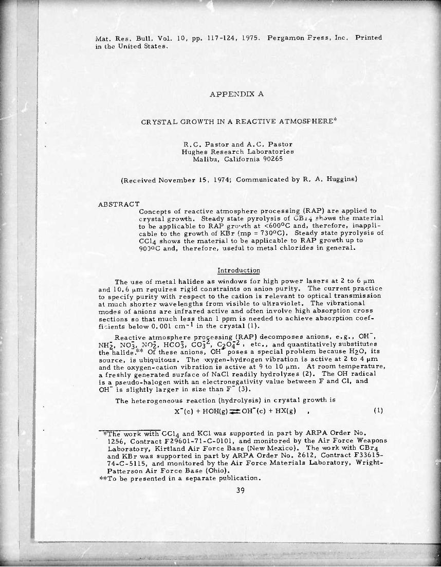
ABSTRACT Concepts of reactive atmosphere processing (RAP) are applied to crystal growth. Steady state pyrolysis of CB14 shows the material to be applicable to RAP gro-vth at <600oC and, therefore, inappli- cable to the growth of KBr (mp = 730oC). Steady state pyrolysis of CCI4 shows the material to be applicable to RAP growth up to 900oC and, therefore, useful to metal chlorides in general.
Introduction
The use of metal halides as windows for high power lasers at 2 to 6 fjim and 10.6 |i.m requires rigid constraints on anion purity. The current practice to specify purity with respect to the cation is relevant to optical transmission at much shorter wavelengths from visible to ultraviolet. The vibrational modes of anions are infrared active and often involve high absorption cross sections so that much less than 1 ppm is needed to achieve absorption coef- ficients below 0.001 cm-1 in the crystal (1).
Reactive atmosphere processing (RAP) decomposes anions, e.g. ■\"2 /-~nTZ
OH" NH2, NO3, NO^, HCO3, CO3 , 0204^, etc., and quantitatively substitutes the halide.** Of these anions, OH" poses a special problem because H2O, its source, is ubiquitous. The -ocygen-hydrogen vibration is active at 2 to 4 |jm and the oxygen-cation vibration is active at 9 to 10 \xm. At room temperature, a freshly generated surface of NaCl readily hydrolyzes (2). The OH radical is a pseudo-halogen with an electronegativity value between F and Cl, and OH" is slightly larger in size than F" (3).
The heterogeneous reaction (hydrolysis) in crystal growth is
X"(c) + HOH(g)^2:OH"(c) + HX(g) , (1)
*The work with CCI4 and KC1 was supported in part by ARPA Order No. 1256, Contract F29601-7 1-C-0101, and monitored by the Air Force Weapons Laboratory, Kirtland Air Force Base (New Mexico). The work with CBr4 and KBr was supported in part by ARPA Order No. 2612, Contract F33615- 74-C-5115, and monitored by the Air Force Materials Laboratory, Wright- Patterson Air Force Base (Ohio).
*5!!To be presented in a separate publication.
39

""■
118 REACTIVE ATM /SPHERE PROCESSING Vol. 10, No, 2
where X" represents a halide, (c) a condensed phase (crystal and/or melt), and (g) the gas phase. The relation of concentrations in the condensed phase to uhe sources in the gas phase is,
(2) C H rx-] " K P(HX) '
where K, the equilibrium constant of eq. (1), is fixed in the crystal growth of a material at its melting point. To achieve a low C, the RAP-inde.", P(H20)/P(HX), must be low.
According to eq. (2), congruent growth with the gas phase based on the provision of a vacuum or an inert gas is characterized by a poor RAP-index, i.e., a high value. While the provision of halogen-hydride (HX) in the gas phase is an improvement, the RAP-index is limited by H2O sources: the HX gas, moisture content of the charge and the outgas, corrosion action of HX on oxide surfaces, etc. These procedures focus solely on the manipulation of the gas phase.
Other orocedures focus only on the condensed phase, e.g., the scaven- ging of O-^in CaF2 melt by PbF2 (Ref. 4),
PbF2(c) + 0"2(c)5^2 F"(c) +PbO(c) . (3)
Excess PbF2 and PbO are volatilized. Residual amounts of the scavenger throttle the growth rate. Also, the effectiveness of scavenging is subject to the RAP-index because,
2 OH"(c)^iO"2(c) +H20(g) . (4)
If the RAP-index is high, it can be shown from eqs. (1), (3), and (4) that the net effect is the hydrolysis of PbF2 in the CaF2 melt by H20(g).
An effective RAP procedure provides both paths for scavenging OH"(c) and H20(g) at rates faster than provided by the sources. Thus, eq. (1) is represented as the sum of two partial reactions. For instance the equivalent of RAP with X2(g), COX2(g) and CX^g) is as follows:
(a) X"(c) +HX(g) +(l/2) 02^i:OH"(c) + X2(g) |
5 (5) (b) X2(g) + H20(g)^r2 HX(g) + (1/2) 02(g)
(a) X_(c) + HX(g) + C02(g)^i:OH"(c) + COX2(g)
(b) COX2(g) + H20(g):=t2 HX(g) +C02(g)
(a) X-(c) + HX(g) + (1/2) C02(g)^tOH"(c) + (l/2) CX4(g)
(b) (1/2) CX4{g) + H20(g)-^S:2 HX(g) + (i/2) C02(g) .
(6)
(7)
Note that the partial reaction (b) of each reaction couple of eqs. (5), (6), and (7) throttles the RAP-index since two moles of HX are formed at the ex- pense of one mole of H2O. RAP with X2, eq. (5(b)), is most effective only for X2 = F2. With X2 = CI2, RAP begins to be effective at >700oC where chlorine becomes more oxidizing than oxygen. But with X2 = Br2, this cross- over is at a temperature much above the melting point of metal bromides, and in X2 = I21 the reaction is displaced even farther to the left.
40

Vol. 10, No. 2 REACTIVE ATMOSPHERE PROCESSING 119
Table 1 is a comparison of the three RAP procedures for chlorides. ^0 Pns (5b) (6b). and (7b). The thermodynamic value of the RAP-index ; calculated for the case where the source is at 0.1 atm and the initial value
of P(H?0) = 10-4 atm.* It is seen that Cl2 is the poorest RAP agent of the three In KC1 growth (mp = 1049oK). the RAP-index of Clz is approximately the equivalent of HC1 with a dewpoint (-6OOC) considerably above its bor.ing point (-850C).
TABLE 1
RAP-index For Chlorides From 600° to 1200 K
T. 0K Cl2 RAP COCI2 RAP CCI4 RAP
600 0.51x10⁻³ 0.47x10⁻²² 800 0.55x10⁻⁴ 1.4x10⁻²⁰
1000 1.3x10⁻⁵ 0-43xl0-8 1200 0.56 x 10⁻⁵ 0.43 x 10
1. 0, 1 0
2 x 83 1 X 62
10-20
x io-18
10-17 x 10-16
The use of CCI4 is preferred over that of COCI2 ease of handling. Now. CX4 pyrolyzes to yield nasce
cx4—^cx3 + x .
because of toxicity mt X (Ref. 5).
and
(8)
which presents the possibility of chain propagation.
(a) CX3+CX4-*C2X6 tX (9)
(b) x + cx4-«-x2 +cx3 . 1
Termination reactions yield more ^X^ and X^,
(a) CX3 +CX3-^C2X6 (10)
(b) x + x-^x.
The advantage to having X is in the electron-transfer reaction.
X + OH"-^X' + OH , (H)
where the free energy change for the forward displacement in the gas phase.
gas phase-condensed phase interface as a resonance transfer between X (c) and X at the interface brings X(c) in the proximity of OH (c).
The net reaction of the above pyrolysis is CX4-*(l/2)C2X6 + (l/2) X2 . (12)
Unfortunately, there is another competing path in pyrolysis. CX4—C + 2 X2 . (13)
*The equilibrium constants as a function of temperature were obtained from. "Thermodynamic Properties of 65 Elements "Their Oxides. Halides. Carbides, and Nitrides." by C.E. Wicks and F E. Block. Bull. 605 of the Bureau of Mines (U.S. Government Printing Office. 1963).
41

120 REACTIVE ATMOSPHERE PROCESSING Vol. 10, No. 2
From the preceding discussion, the latter path is undesired except for X2 = F21 in which case the forward displacement is negligible even at 20(.0oK. Assigning t to the probability of the path given by eq. (13) and 1-f to eq. (12),
(14) CX, f C + (1 - f)/2 C2X6 + (3f + i)/2 X2
The temperature range in which the decomposition of CX4 is high, and the value of f low, is applicable to RAP crystal growth of the corresponding metal halide.
Two sources of interest to RAP crystal growth with CX4 are CBr4 and CCI4. We report below the results of studies on the steady-state pyrolysis of these sources and their application to RAP crystal growth of KBr, KC1, and NaCl.
Experimental
Figure 1 shows the schematic of the pyrolysis apparatus. The pyrolysis chamber (quartz) is capable of a constant linear flow, i.e., the cross- sectional area of the central tube equals the annular area. At a flow of 1 cm3/sec (carrier gas + RAP agent), the residence time is ~200 sec. A similar design was adopted for the solid source CBr4 where, for the same flow, the residence time is 20 seconds. The chamber heater was driven with a thermocouple controller (± 50C).
All fittings, stopcocks, and connecting tubings were made of Teflon. The source containers were Pyrex. Tue CCI4 bubbler was coarse grade frit. Helium (>99. 99% pure) was the carrier. A 3- and 2-way stopcock arrange- ment was provided for helium to bypass the source. Pyrex wool and a long vertical section of the tubing leading to the chamber were employed to trap
PYREX WOOL
C-^RIT
CBr4 SOURCE
MEASURE FLOW OR CONDENSATE
THIOSULFATE SOLUTION WITH STARCH-KI INDICATOR
CCI4 SOURCE
Figure A-l
Schematic of pyrolysis apparatus
42

Vol. 10, No. 2 REACTIVE ATMOSPHERE PROCESSING 121
entrainment by helium. A flowmeter (upstream, not shown) was used to monitor flow settings but the actual flow was measured at the exit end of the apparatus by water displacement. At the exit, unpyrolyzed CCI4 was mea- sured by condensation; Br?. and Clz in the exit gas were chronometncally titrated with a known volume of 0. 0201 WNazSzOs using starch-KI mdicator. The exit tubing was provided with a heating coil to prevent clogging by the deposit of C2X^.
The source temperature was hnld at 240C. At each setting of the pyrol- vsls temperature, the steady-state flow was determined from five samplings. Five to six titrations followed, spaced at regular time intervals, to deter- mine the steady-state concentration of X2 in the effluent. The amount of Na s O^ per titration corresponded to a gas sampling of a volume less than or equal to the volume of the pyrolysis chamber. After the last titration, the flow was again measured.
The RAP crystal growth of KBr and KC1 (and NaCl) were carried out in a vertical Bridgman apparatus, using quartz crucibles of 3 to 10 cm i.d. Helium, the carrier gas for the RAP agent (CBr4 and CCI4). flowed at ~0 5 cmVsec. The flow arrangement was similar to that used in pyrolysis, with a growth apparatus replacing the pyrolysis chamber. At the exit end, check out titrations were also made but most of the time the exit gas was scrubbed of its Xz and CX4 contents with NaOH solution. The melt was soaked for ~100 hr and cr^tal growth was carried out at a lowering rate of 1.5 to 3 mm/hr.
Results and Discussion
Data being unavailable, the saturation pressure of CBr^s) was deter- mined using the CBr4-source apparatus (cf. Fig. 1). Helium was the carrier. At a given temperature setting of the source and flow of helium, or residence (saturation) time, the partial pressure of CBr4 was calculated from the weight loss incurred through a given time interval. Pyrex wool plugs were employed vo strip out mechanical entrainment in helium. At constant temperature, the partial pressure Increased with decreasing flow, reaching a constant value, the saturation pressure, a* a flow <1 cm^/sec, or a resi- dence time >20 sec. The results are shown in Table 2. The variation of saturation (sublimation) pressure with temperature (cf. Fig. 2) corresponds to an enthalpy change of 14.0 kcal/mole.
TABLE 2
Partial Pressure of CBr4(3) Versus Helium Flow
Temperature, 0C
Saturati Time,
on s
Total Flow Time, h
Partial Pressure, mm
Saturation Pressure, mm
0.0 20 35
18.0 17.8
0.0697 0.0702 0.070 ± 0.000
23.0 32 41
120
16.3 22.5 67.0
0.462 0.494 0.464 0.473 ± 0.01G
50.0 49 72
2.5 4.0
3.75 3.82 3.79 ± 0.04
43
.

"""""■H
122 REACTIVE ATMOSPHERE PROCESSING Vol. 10, No. 2
10
E E
5 GD O
3291
CBr4(s) ^ CBr4(g)
SUBLIMATION 14.0 kcal/mol
3.00 3.20 340 lO3/!, 0K
I I I I I
3.60
60 40 20 0
Sublimation
Figure A-2
pressure of CBr^
Pyrolysis measure- ments were carried out with helium as the carrier at various temperatures (tp 0C). The source tem- perature was 240C, which corresponds to a satura- tion concentration of c = 2.55 x lO-8 mole/cm3
for CBr4 and c = 5.40 x 10"° mole/cm3 for CCI4. At the exit, the steady-state concentra- tion, [X^Jijcj in mole/cm , is
N" (mol es x2) vt ,(15)
where v is the flow in cm3/sec, t is the time required to attain end- point with a given amount of Na2S203, and (moles X2) = (moles Na2S203)/2. From eq. (14), f can be calculated from
N ss (3f + l)c y
2 (16)
where y is the fraction of '3X4 unpyrolyzed; 1 - y is determined at the exit.
74 versus temperature
Table 3 gives the results obtained. From the value of f, it is appreciated that RAP crystal growth with CBr4 is applicable at working temperatures <600oC. It is not applicable to KBr growth from the melt because at the melting point (730oC) pyrolysis is dominated by eq. (13). However, RAP crystal growth with CCI4 is applicable up to 900oC and is, therefore, useful to the congruent growth of metal chlorides in general. At the melting point of KC1 (7760C), the reaction path shown in eq. (12), i.e., involving the formation of X, is four times favored over that of eq. ^13).
As expected, attempts to grow KBr in a quartz crucible by the vertical Bridgman method, have failed with CBr4 as the RAP source. The melt per- sisted in wetting the crucible, an indication of partial hydrolysis.* Con- sequently, although one succeeded in growing a single-crystal ingot, the crystal and/or crucible cracked during cooldown.
This behavior provides a useful indicator on the reduction of OH" (or O ) content in the melt. In the case of fluorides, carbon or platinum crucible serves the same purpose. At very low concer.Liations of OH~ ir RF3 (R = a rare earth), nonwetting of platinum persists from the liquid (melt) to the solid (crystal).
44

Vol. 10, No. 2 REACTIVE ATMOSPHERE PROCESSING 123
TABLE 3
Steady State Pyrolysis, CBr4 Versus CCI4 (He Flow <1 cm /a)
CBr4 •2.55 x 10 "° mole/cm3 cci4 5.40 x 10 "" mole/cm3
t 0C p
Y f mole Br2/cm3 Y f mole Cl2/cm3
400 500 600 700 800 900
0.17 ^1.0
1.0 1.0 1.0 1.0
0.0 ,50.11
0.48 0.92 1.0 1.0
0.22 x 10⁻⁸
1.7 x 10⁻⁸ 3.1 x 10⁻⁸ 4.8 x 10⁻⁸
5.2 x lO'8
5.5 x 10⁻⁸
<0.00 -0.20
0.85 <0.9 -0.9
0.0 -0.17
0.22 >0.22 -0.20
1.9 x 10⁻⁸ 0.82 x 10⁻⁶
3.8 x 10⁻⁶ 4.0 x 10⁻⁶
3.9 x 10⁻⁶
The situation was different in the case of KC1 and NaCl, grown by the vertical Bridgman method in quartz crucibles with CCI4 as the RAP source. The single-crystal ingot slipped out easily and the crucibles were reusable over and over. This feature was reproduced in the growth of 3 to 10 cm diameter ingots. Figure 3 is an example of such an ingot (KC1).
A comparison of the steady state effluent, KC1 RAP growth versus pyrolysis of CCI4, was made. Growth at 800oC, with v = 0.5 cmVsec, gave 15 millimoles Cl;? per hour. Pyrolysis at 800oC, with v = 0.8 cm5/sec, gave 12 millimoles Ci2 per hour.
Noteworthy improvements over previously available materials have re- sulted in the performance parameters of these anion-ultrapure materials. The measured optical absorption of RAP KC1 in a 10.6 ^m CO2 laser calorimeter yields an absorption coefficient of 0.00013 cm-1, which value is
Figure A-3
A 10-cm diameter single-crystal KC1 grown by RAP-Bridgman with CCI4 in He at a flow
of -0.5 ^/s
45

124 REACTIVE ATMOSPHERE PROCESSING Vol. 10, No. 2
more than an order o;: magnitude lower than that of earlier vintage materi- als (7). Also, with a 0.6 jis pulse, the CO2 laser damage threshold of RAP KC1 crystal is >7.8 x 10⁹ W/cm2, which is many orders of magnitude larger than the value reported earlier.* The fracture strength, as measured by 4-point bending (Instron) exceeds 4000 psi, which value is also about one order of magnitude larger.
We are grateful to R. R. Turk of Hughes Research Laboratories for the measurement of fracture strength.
References
1. C.J. Duthler, J. Appl. Phys. 45, 2668 (1974).
2. D. Otterson, J. Chem. Phys. 33.. 227 (I960).
3. R.C. Pastor and M. Robinson, Mat. Res. Bull. 9, 569 (1974).
4. D.C. Stockbarger, J. Opt. Soc. Am. 5|, 731 (1949).
5. A.H. SehonandM. Szwarc, Proc. Roy. Soc. A209, 110(1951).
6. V.l. Vedeneyev, L.V. Gurvich, V.N. Kondrat'yev, V.A. Medvedev and Ye. L, Frankevich, Bond Energies, lonization Potentials and Electron Affinities. St. Martin's Press, New York, N.Y. (1966).
7. F. Horrigan, C. Klein, R. Rudko, and D. Wilson, Microwaves 8^, 68 (1969).
Laser calorimetry and damage measurements by S.D. Research Laboratories (private communication).
46
Allen of Hughes

Mat. Res. Bull. Vol. in the United States.
10, pp. 261-266, 1975. Pergamon Press, Inc. Printed
APPENDIX B
CRYSTAL GROWTH OF KBr IN A REACTIVE ATMOSPHERE
R, C. Pastor, A.C. Pastor, andM.A. Aaronson Hughes Research Laboratories
Malibu, California 90265
(Receiver" February 6, 1975; Communicated by R. A. Huggins)
ABSTRACT Reactive atmosphere processing (KAP) with bromomethami derivatives is employed in the crystal growth of KBr (mp = 730OC). Derivatives with higher C-Br bond dissociation energy are found to be applicable.
Introduction
The pyrolysis of carbon tetrahalide, CX4, in an inert gas (e.g. , He) occurs with two competing reactions.
CX4 -fC + (1 - f)/2 C2X6 + (3f + l)/2 X. (1)
where f = 1 is the undesired path, while f = 0 is the desired path where the nascent halogen is an intermediate (1). The objective of the application of reactive atmosphere processing (RAP) to crystal growth is to attain a low value of f in the pyrolytic breakdown of the RAP agent in a temperature range which includes the melting point of the metal halide in question.
Although CBr. may prove to be applicable to RAP growth at tempera^ tures well below 6D0OC, it is inadequate for the growth of KBr (mp =7 30 C) because f = 1 at temperatures >700 C (1). In the case of CHB^, J
similarly inadequate for the growth of KBr. it is
The case of f = 0 in eq. (1) may be rewritten to show explicitly the formation of the nascent form of the halogen.
CX.—CX, 4 : + X
The decay constant, k, of eq. (2) is found ,0 be represented by
k = v exp r-D/'RT) ,
(2)
(3)
*This work was supported in part by AF PA Order No. 2612, Contract F33615-74-C-5115, and monitored by the Air Force Materials Laboratory, Wright-Patterson Air Force Base (Ohio).
47

Z62 CRYSTAL GROWTH OF KEr Vol. 10. No. 4
1 frequency and dissociation energy, = :.75 x 1013 sec-1 (K«f. 3). For ci
where v and D are th*. C-X bond respectively (2). For C-Er, v = 1.75 x 10X1 sec'* (K«f. 3). For crystal growth, the value of k must be constrained to 0 < k < 1 at the melting point of the metal halide in question. At k = 0 no nascent halogen is formed; but at k > 1, the gas enteiing the growth apparatus is readily pyrolyzed befora reaching; the melt and the nascent form is readily lost.
X + X — X. (4)
We have shown previously that the riolecular halogen form, except in the case of X? = F2, is an inadequate RAP agent for the growth of alkali metal halides (1).
At the melting point of KBr, T = l003OK; for k < I in eq. (3), it follows that C-Br must have D> i\T Inv or D > 61 kcal. This constraint provides the basis for explaining the inadequacy of CBr4 and CHBr, to RAP growth of KBr because the values of D are 49 and 56 kcal, respectively (4).
Consequently, other derivatives, CX4_ . With Y being an atomic subslituent more strongly covalently
..nYr, wh«-i:e n = 1, 2, or 3, v considered. bonded than X (i. e. , H or another halogen), the two paramerers, Y and n, provide a graded increase in the dissociation energy of C-X, Thus, in the case of X = Br, the D values for C-Br arf. (Ref. 4): CBrAf 49; CHBr,, 56; CH2Br2, *'.■••.■!<>'.-.'■' .,,.,. 63; CH3Br, 67; and CF.Br, 65 (unit: kca!),
An increase in the value of D will shift the onset of pyrclysis to higher temperatures. The choice of Y is such that DC_Y > D- x; .&. , thermal dissociation of the C-Y bond should be much les's probable H an C-X. How- ever, if compounds such an YX (Y = H and interhalogcn radii als* -^re formed, then the C-Y bond rmy be ruptured by YX splitHrg cff in the colli- sion of the parent molecule with nascent X or another p.v> ir.t molecule A good part of the energy required for the C-Y bond ruptoV« iä n^w pro^ tied by the energy derived from the formation of the Y-X bond. If TX is not easily dissociated (as in Y = H), the chain-propagation step acts merely as a sink for nascent X (1). If YX is easily dissociated (as in Y - another halogen), the formation of mixed halides in the melt presents a complication.
Experimental
A description of the pyrclysis apparatus and p ^dure were given pre- viously (1). In the case of the RAP agents, CH2Br- >J. T. Baker Co.) and CF,Br (Matheson Gas Products), the pyrolycis chamber was laid hori- zontally to accommodate silica boats loaded with KBr powder, reagent gradt (Klatheson Coleman and Bell). The pyrolysis residence time was ~200 sec at a flow of 1 cm /sec. After a run, nonwetting or wetting of the crucible by the melt was deduced by an examination of the polycrystal- line cast.
At the exit, the steady-state concentration of Br-> was measured by the time required to attain endpoint with a given volume of C. 0201 N Na>S203, using starch-KI solution as the indicator (1). The steady-state concentration of HBr was measured indirectly. Known amounts of N^HM were present in the solution which readily converted Br^ to HBr. Total HBr was measured by the time required to attain endpoint witn a given volume of a freshly made up 0. 0603 N NaHCO?, using bromcreool green as the indicator. Titration blanks were run to allow for a corr ion tc
48

Vol. 10, No. 4 CRYSTAL GROWTH OF KBr 263
j
unreacted ^2^^-
The RAP crystal growth of KBr was carried ^^^^^ST
apparatus. «^ ^f^ Ä ^ arrangement was similar to that emPl°yeÜ/" ^ e^t was scrubbed of
^5 hoCs and crystal growth was carried out at a owermg rate of ~2 mm/ Lur rth cSzBrJ/He.'while in the case of CF3Br/He. the soak was ~3 hours and ^lowering rate was ~5 mm/hour.
saw. A. »f«»^"?^ »'.f'^^„lon in the waveUneth .ange of 2. 5 to S^^'^VÄS « S«r.d spectrophotometo, (Becfan.n IB U).
Results and Discussion
S.' ^ «tU%o." «weh '"-^••^'(B'.'i 1 -''A —*
d.,o.U |orm. '" *« P*™1^ ^ S hVH.r d.".iTol <? upstream. Indl- thermalization by C02 is seen in me nca f reeion and at a low eating that pyrolysis occurs at a ^-^t^low'emperature region, the fraction «J ^total residenc^time ^At th^lo^ .mpera^^ gi ^
[rallono^evTdinTeof Td^crease (n ^ogenconc^ntraUon^th increase m temperature when the carrier gas is changed from He to CUZ, i.e., S
gible formation of COB^.
The results of PY-lysis of CH,Br2/He is collected in T^e IT As
seen in the ^f^^^l^f^l mln it L^U «W w ^ Vh^ur Ice ^ heW ar200oC for 19 Hour, to dry the KBr The Si,d Jol^n g^s the CH2Br2 content of the carrier gas (He) at a 25 C
saturation.
The fourth and fifth columns show thai Br2 and «f .^^^f as low as 200OC. While Br, ^^Br^tS with further increase - te^e^rature^HBr^ormatio^^ ^ ^ ^^ ^ ly with temperature. At 500oC. the HBr concentration is one order ot ire. AV JU" »-'l "" aaa-.» -—
aL f f^e.-a Rv and at 900 C. the concentration ma?n«ode l^ger than hat of ^^^ J*. ^ f.' formati„n of HB, at ratio is ~10 . These res^u Unimolecularly or bimolecularly, occur, low temperatures fro1" C"2Br2' ^im°leC^ the
yhi her temperatures sug-
The drop in the concentration of free Br. at tne ™g reaction of gests a second mechanism for the formation «£ HBr• ^ ^^ * Lscent Br or ^lecul.rBr ^ CU^2. AUh^gh t^ ^ ^ .^^ CH2Br has a bond «n«gy Ö ^ ^f £ H^r (4). ^ is tor the case ment of only 11 kcaa be"use u investment is 57 kcal, which value of nascent Br. For molecular Br2, me "^ is still less than the C-Br value for CH2Br2 (D - bi Kcai,.
..pe^t^r^^^Ä^^^^^^ 49

264 CRYSTAL GROWTH OF KBr Vol. 10, No. 4
nascent bromine on the OH" impurity in the RAP growth ol KBr. The gas- phase formation of HBr favors a lower RAP-index (1) but not at the expense of the H~0 species being converted to HBr at a 1:2 stoichiometry. Repeated crystal growth runs indicated that C^B^ may still be a borderline.case RAP agent for the growth of KBr. Sections of the ingot adhered to the cru- cible (vitreous silica).
TABLE I
Pyrolysis of CBr4/He and CBr./CO.,
0c (Mole Br /crn ) x 10
CBr./He CBr4/C02
400
500
600
700
800
900
0.22
1.7
3. 1 ± 0. 1
4.8 ± 0.2
5.2 ± 0.2
5.5 * 0.4
3.2 ± 0. 1
4.7 ± 0. 1
5.2 ± 0.2
5.4 ± 0. 3
Saturation of carrier gas between 24 to 25 C corre- sponds to (mole B^/cm^) x 108 = 5. 5 ± 0.4 at 100% pyrolysis.
TABLE 11
Pyrolysis of CHjBr./He
0C Input Output
Pyrolysis, % Total Flow,
cm^/sec Aa Bb cc
200
400
500
bOO
700
800
900
0.44
0. 44
0.43
0.43
0.43
0.43
0.42
1,04
1.03
1.03
1.01
1.01
1.01
1.01
< 1 06
3.79
11.9
7.09
1.95
< 1.0
<0. 50
< 1.8
43
163
189
192
217
244
<0. 18
4.2
16
18.7
19.0
21
24
aA ■ (mole CH-,Br?/scc) x 10 . equals the theoretical output of (mole Br^/sec) x 10° for 100% pyrolysis.
B - (mole B^/s^c) x 10 by thlosulfate titration.
CC a (total mole Br2/sec) x 10 from Br2 and HBr/2.
dPyrolysis % = C/(10A).
The above results suggested the use of CF-jBr instead of CH-jBr. A 10 mole% mixture in He was obtained (Matheson Gas Products). Molecular weight determination with a 5-liter bulb (Regnault method) showed the com- position to be 11.4 ± 0.2 mole%. The pyrr lysis furnace, with CF3Br/He flowing at ~0. 3 cm^/sec, was held at 200 C for 15 hours to dry the KBr. Table III gives a summary of the results obtained in the pyrolysis of CFjBr/He.
Unlike the case of C^Br^He (cf. Table II), Table III shows that Br2
formation increases monotonically with tei.iperature in the pyrolysis of CF,Br/He. Although the bromine-atom content of the gas entering is about a factorof two larger in CH^B^/He (compare the A values), note that at 800OC the Br^ output is aLout three orders of magnitude smaller than that of CFoBr/He. No visible deposit of C in the melt resulted, i. e. , low f value in eq. (1). The frozen KBr showed that the melt assumed a nonwett- ing meniscus. Natuially, the polycrystalline ingot was easily removed from the quartz boat. Fip^re 1 shows the polished pieces of KBr fabricated from the ingots grown under C^B^/He and CFßBr/He.
The infrared transparency of these specimens was examined with the Beckman IR 12. The KBr grown in CH2Br2/He, diameter = 3.0 cm and length = 1.4 cm, showed a flat transmission from 2. 5 to 18 |J.m and the knee of the curve was at 20 fim, in agreement with the behavior reported in the literature (6). The KBr grown in CF-jBr/He, diameter = 1.6 cm and
50
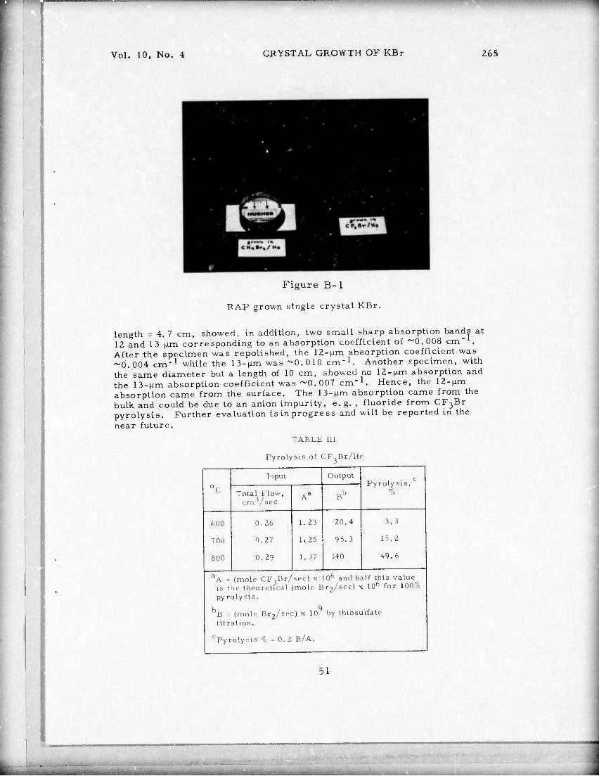
Vol. 10, Mo. 4 CRYSTAL GROWTH OF KBr 265
Figure B-l
RAP grown single crystal KBr.
length = 4.7 cm, showed, in addition, two small sharp absorption bands at 12 and 1 3 \im corresponding to an absorption coefficient of ~0. 008 cm' . After the specimen was repolished, the 12-|J.m absorption coefficient was ~Ö,004 cm"1 while the 13-|j.m was ~0.010 cm"1. Another specimen, with the same diameter but a length of 10 cm, showed no 12-fjm absorption and the 13-HLm absorption coefficient was ~0.007 cm"1. Hence, the 12-fi.m absorption came from the surface. The B-JUM absorption came from the bulk and could be due to an anion impurity, e. g. , fluoride from CF3Br pyrolysis. Further evaluation is in progress and will be reported in the near future.
TABLE III
Pyrolysis of CF Br/He
0c Input Output
Pyrolysis, % Total Flow,
crn^/sec Aa Bb
600
700
800
0. 26
0.27
0. 29
1. 23
1.25
I. 37
20. 4
95.3
340
3. 3
15.2
49.6
aA s (mole CF^Br/sec) x 106 and half this value- is the theoretical (mole Br2/sec) x 10fa for 100% pyrolysis.
B = (mole Brz/sec) x 10 by thiosulfatc tit rat ion.
cPyrolysis % = 0.2 B/A.
51

1
266 CRYSTAL GROWTH OF KBr Vol. 10, No. 4
References
1. R.C. Pastor and A. C. Pastor, Mat. Res. Bull. JMD, No. 2 (1975).
2. A.H. Sehon and M. Szwarc, Proc. Roy. Soc. A209, 110 (1951).
3. L. J. Bellamy, The Infra-Red Spectra of Complex Molecules. John Wiley and Sons, Inc. , New York (1956).
4. V.I. Vedeneyev, L.V. Gurvich, V.N, Kondrat'yev, V.A. Medvedev, and Ye. L. Frankevich, Bond Energies, lonization Potentials, and Electron Affinities. St. Martin's Pi-ess Inc., New York (1966).
5. R.C. Pastor and A. C. Pastor, submitted to Mat. Res. Bull.
6. See page 36 of Harshaw Optical Crystals, Copyright 1967, from the Harshaw Chemical Co. (Ohio). See also Bulletin 50, Optical Crystals, 1969, from Optovac Inc. (Mass.).
52

Mat. Res. Bull. Vol. 10, pp. 251-256, 1975. in the United States.
Pergamon Press, Inc. Printed
APPENDIX C
CRYSTAL GROWTH OF KC1 IN A REACTIVE ATMOSPHERE
R.C. Pastor and A.C. Pastor Hughes Research Laboratories
Malibu, California 90265
(Received February 14, 1975; Communicated by R. A. Huggins)
ABSTRACT Reactive atmosphere processing (RAP) with CCI4 is employed in the crystal growth of KC1 (mp = 7760C). Two carrier gases. He and CO2, are compared. A carbon deposit accumu- lates in the growth of KC1 in CCl/j/He, a drawback which is eliminated in crystal growth under CCI4/CO2.
Introduction
In a previous publication, certain concepts of reactive atmosphere pro- cessing (RAP), as applied to crystal growth, were discussed (1). It was pointed out that the pseudohalide impurity, OH", poses a special problem be- cause HoO, its source, is always present in all steps of processing, including crystal growth. To achieve a low ratio of OH" to X" (halide ion) in the con- densed phase, the chosen reaction must be capable of constraining the gas phase to a very low value of the RAP-index, P(H20)/P(HX).
For crystal growth of the corresponding metal halide, CX4 was chosen in the study as the RAP agent because of its capability to provide the nascent form of the halogen (2). Unfortunately, in CX4 the oyrolysis in an inert carrier (He) occurs with two competing reactions,
CX, fC + (1 - f)/2 C2X6 + (3f + l)/2 X2 (1)
0 is the desired path where the where f = 1 is the undesired path, while f nascent halogen is an intermediate (1).
The objective in RAP crystal growth is to attain a low value of f in the pyrolytic breakdown of the RAP agent over a temperature range which includes the melting point of "he metal halide. Thus, CB^ proved to be an inadequate RAP agent for the growth of KBr (mp = 730 C) because f = 1 at temperatures 2700ÖC, while CCI4 was applicable to the growth of KC1 (mp = 776^) because the f = 0 oath was four times more probable than the f = 1 path from 700 to 900oC M).
*This work was supported in part by ARPA Order No. 2612, Contract F33615-74- C-5115, and monitored by the Air Force Materials Laboratory, Wright-Patterson Air Force Base, Ohio.
53

252 CRYSTAL GROWTH OF KC1 Vol. 10, No. 4
The above studies were carried out with an inert carrier (He). A draw- back in the growth of KC1 under CC^/He arises because the value of f is not close to zero. For long processing times, the generation and accumulation of C and Cl? lead to various problems. The deposited C may be a contributing factor to significant deviations of the ingot from monocrystallinity and, not infrequently, greatly reduces the utilizable fraction. The excessive buildup in Cl? provides the limiting factor to the lifetime of the growth apparatus. With the object of overcoming these drawbacks, a reactive carrier gas was studied. We report here the results of such a study using CO2 as the carrier gas for CCI4.
Experimental
A descriotion of the pyrolysis apparatus and procedure was given pre- viously (1). The temperature of the source (CCI4) was held at 24 C, which corresponds to a saturation concentration of 5.40 x 10"6 mole CCWcm-5 in the gas phase. The total flow of carrier gas and CCI4 was maintaiied at MD.8 cm^/sec or a residence time, x, in the pyrolysis chamber of ^4 min. The fCU liquid is reagent grade (J.T. Baker Chemical Company). The purity of He was >99.99/i (Airco) and CO2 was >99.9% (Matheson Gas Products).
At the exit, the steady-state concentration of Clp was measured by the time required to attain endpoint with a given volume of 0.0201 N Na2S2C13. using starch-KI solution as the indicator (1). The total flow was measured by water displacement.
The RAP crystal growth of KC1 was carried out in a vertical Bridgman afparatu?, using vitreous silica crucibles of 3 cm i.d. The carrier gas (He or CO2) for CC14 flowed at ^0.5 orrVsec. The flow arrangement was similar to that used in pyrolysis, with the growth apparatus replacing the pyrolysis chamber. At the ent, titrations for CI2 have been made which check out with the resujts of pyrolysis (1). The exit gas was scrubbed of its Cl2 and CCI4 contents with NaOH solution. The melt was soaked for ^65 hour and crystal growth was carried out at a lowering rate of ^2 mm/hour.
The single-crystal ingots were cut into 10-cm length cylindrrs with a string saw. An optical finish at the ends was obtained by polish!.-" with Linde A in methanul. The infrared transmission in the wavelength r iige of 2.5 to 20 \im was measured with an infrared spectrophotometer (Beckman IR 12).
Results and Discussion
A comparison of the steady-state concentration of CI2 in the effluent in the pyrolysis of CCI4/HP and CCl^/COg, at approximately equal residence times, T, in the oyrolysis chamoer, i's given in Table I.
It is seen that at 500oC, the rate of halogen formation is ^200% higher in the C0? carrier. This feature may be explained by the difference in molecular mass and heat capacity of the carriers, CO2 being the more effi- cient therrr^lizing agent. The difference in the rate decreases with an increase In the oyrolysis temperature; the crossover is at 700 C. From 700 to 800 C, the rate of halogen formation increases with He carrier gas but decreases with CO2. The latter behavior is due to a significant reactivity
Complete pyrolysis by f = 0 pa and by f = 1 oath, 2.70 x lO-6
th in eq. (1) yields mole Cl2/cmJ.
54
.08 x 10"5 mole C^/cm3

Vol. 10, No. 4 CRYSTAL GROWTH OF KC1 253
TABLE I
Pyrolysis of CCl^/H« and CC14/C02
\ CC14/He cci4/co2
T, min A x lO83 8a
T, min A x 10
500
600
700
80f-
3.9
3.7
3.8
3.7
0.9".
41.2
191
201
3.8
3.9
4.1
4.1
2.8
49.0
191
181
aA = mole Cl2/cm3 in the effluent.
of C02 to the carbon deposit resulting from the f = 1 brancn of eq. (1),
C + C02 ^ 2 CO ,
and the resulting CO tying up the free chlorine (3),
CO + Cl, :oci,
[2)
(3)
For a 20-hour pyrolysis at 800 C, a light carbon deposit formed in CCVHe but none in CCl4/C02. This feature was reproduced in crystal growth as seen in Fig. 1. Note in the case of the KC1 ingot grown from CC^/He that the last one-eighth fraction cannot be utilized as it is densely packed with bubbles.
Window specimens, 10 cm in length, were fabricated from the ingots shown in Fig. 1 for infrared transmission measurement in the Beckmün IR 12. The transmission curve was flat at ^94% transmission from 2.5 to 12.5 \im with the knee of the curve at 14.5 m for both soecimens. In the ten "■ ,o-i tange, the deviations are SÖM which result indicates that the absorption coeffi- cient at 10.6 urn (C02 laser calorimetry) would differ by <0.000b cm
-1 between the two specimens.
The results of infrared transmission measurements are significant to the objective of RAP growth, vjz., remc al of anion impurities. With C02 as the carrier, the presence of 0 and OH' Impurities in the melt would have led to the formation of CO, and HCOj impurities, respectively:
(4) co2 + 0 ^C0-
and
It is not unlikely that the bimolecular reaction, COp + CCIa + 2 COCI2, is occurring in the gas phase; hence, two sources for COCl?. ihe latter hydrolyzes easily and is removed from the exit gas by trie scrubber, COCI2 + 2 NaOH * 2 NaCi + HoO + CO.
DO
. .-. J_^-„„.„^_
254 CRYSTAL GROWTH OF KC1 Vol. 10, No. 4
Figure C-l
Bridgman KC1 ingots grown under CCl4/He and CCI^/CO,?.
co2 + OH" -HCO: (5)
In lO-cm length KC1, an imourity level of 100 ppm CO? would have shown ab- sorption bands from 6.5 to 14.7 ym, while 0.1 ppm HCO3 would have given ab- sorotion bands from 3.0 to 15.9 \m (4).
From eqs. (4) and (5), one c-'n show that the HCO3/CO3 ratio is depend-"- ent on the 0H"/0 ratio which, in turn, is dependent on H9O. It will be recalled that the latter is governed by the RAP-index. The results obtained indicate that the RAP growth procedure provides g very low value of the RAP- index and also effects an efficient removal of 0 imourity in the condensed phase.
We thank M. Aaronson for the infrared transmission measurements on the
KC1 crystals.
56

m
Vol. 10. No. 4 CRYSTAL GROWTH OF KC1 255
References
!. R.C. Pastor and A.C. Pastor. Mat. Res. Bull. 10 No. 2 (1975).
2. A.H. Sehon and M. Szwarc. Proc. Roy. Soc. A2Qi 1-0 V™)'
3. See p. 403. Mellor's Modern Inorganic Chemistry, edited by G.D. Parkes
(Longmans. 1967).
4. C.J. Duthler. J. Apol. Phys. 45 No. 6. 2668 (1974).
57
1

Mat. Res. Bull. Vol. 10, pp. 493-500, 1975. in the United States.
Pergamon Press, Inc. Printed
APPENDIX D
CRYSTAL GROWTH OF ALKALINE EARTH FLUORIDES IN A REACTIVE ATMOSPHERE*
R.C. Pastor and K. Arita Hughes Research Laboratories
Malibu, California 90265
(Received April 4, 1975; Communicated by R. A. Huggins)
ABSTRACT Crystal growth of MF2 (M = Ca, Sr, or Ba) is carried out in a reactive atmosphere consisting of HF and a carrier gas (He). Single-crystal Bridgman ingots, with the axis oriented at <111>, are grown up to 5.2 cm in diameter. The mechanical strength of T;hese specimens is found to be higher than what has been reported.
Introduction
The ubiquity of water is responsible for the ilmost universal presence of hydroxide ions in halide crystals prepared without special attention to ex- cluding water. For crystals grown from the melt, hydroxide contamination occurs through hydrolysis:
X"(c) + H,0(g) 7* OH"(c) + HX(g) (1)
Equation (1) shows that in the presence of water in the gas phase (g), a halide ion (X") in the condensed phase (c) is replaced by a hydroxyl ion (OH") with the production of the hydrogen halide (HX). From the equilibrium relation, the concentration ratio C, of OH" to X" in the solid, is given by:
K P(H20)
P(HX) (2)
where K is the equilibrium constant and the Ps are partial pressures.
Since the objective is to achieve a low value of C, one must remove the H2O and provide HX. The use of vacuum or an inert gas is not wholly
This work was supported in part by Contracts F3361 5-73-C-5075 and F33615-74-C-5115 (ARPA Order No. 2612) of the Air Force Materials Laboratory, Wright-Patterson Air Force Base (Dayton, Ohio).
59
PRECEDIN3 PAGE BLANK-NOT FILMED
—MWW'^WjliiaM^ Bgp^l'lllli'iTOMIWWiW]JiMw
494 ALKALINE EARTH FLUORIDES Vol. 10, No. 6
effective in achieving a small C because P(Hi>0) is never zero, while P(HX) is essentially zero in those circumstances. The reactive atmosphere processing (RAP) technique employed in the crystal growth of alkaline-earth fluorides (cf. below) differs from the preceding methods in that it provided gaseous HF to drive the equilibrium of eq. (1) to the left.
Control of the RAP-index, P(H20)/P(HX), to a very low value during crystal growth of chlorides and bromides significantly improved the crystal's mechanical strength, infrared transparency, and resistance to laser dam- age (1). In the case of fluorides, such control prevented the occurrence of solid-solid transitions (2), increased the melting point (3), led to a different solid-solution behavior (4), and caused melting-congruency behavior in a system reported to undergo a peritectic reaction (5). We report here the extension of these studies to the growth of the alkaline-earth fluorides.
Experimental
The starting materials were MF2 powders (EM Laboratories) which were rated better than five-nines pure with respect to the cation. In the case of BaF2, the powder was also prepared from five-nines pure Ba'"^ (J. Matthey), using 49% HF solution and completing the conversion with HF gas (3).
A graphitp resistance furnace (Astro Industries) was used to grow the crystals by a vertical Bridgman mode. Vitreous carbon crucible (Beckwith Corporation) was used in the growth of 3-cm diameter ingots by spontaneous nucleation. For 4.3- and 5.2-cm diameter growth, graphite crucibles were fabricated in our shop with the design shown in Fig. 1(a). A seed well was provided for oriented growth at <111>. Loading of the crucible plus MF2 powder charge in the furnace is followed by leak checking, vacuum pumping, and RAP at a low temperature before melting. The reactive atmosphere con- sisted of HF (99. 9%, HzO-content = few ppm) diluted to 10 mole % with He flowing at 2 l/min. The melt is soaked for eight hours; then growth proceeds with the crucible lowered at 2.5 mm/hour and rotated at 1 rpm. After com- pletion of crystal growth the temperature is lowered to room temperature over a 13-hour period by a cam on the temperature controller. Figure 1(b) shows the three sizes of MF2 ingots grown.
The <111> orientation of the 4.3- and 5. 2-cm diameter ingots were verified by x-ray back reflection (Lane) on the portion of the raw ingot which crystallized last. The microhardncs 3 (Knoop) and the mechanical strength (Instron) were determined on unorieated specimens. To determine the infra- red transparency from 2.5 to 10 |j.m (Beckman IR 12), windows were fabri- cated by cutting with a wet diamond-impregnated -yire and given a final polish with an aqueous suspension of Linde A.
Results and Discussion
The results of the emission spectrograph analysis of the MF2 powders as received from EM Laboratories are collected in Table I. It is seen that the major impurities are other members of the alkaline earths. A compari- son of the analysis of the powder and the crystal tail, which correßponds to the initial and final bulk melt compositions respectively, show in ehe case of CaF2 that the last section to crystallize is five times richer in magnesium while strontium is constant at 0.04 ± 0.01 wt%. The behavior of Mg+Z
60

Vol. 10, No. 6 ALKALINE EARTH FLUORIDES 495
(a)
Figure D- 1 Crystal C-owth of MF2
(a) Design of the graphite crucible for the vertical Bridgman growth of MF2 single-crystal ingot oriented in the <111> direction.
(b) Scale up in the crystal growth of MF2: ingot diameter 3.0, *4 3 and 5. 2 cm.
TABLE I Emission Spectrograph Analysis'1 of EM Ultrapure MF, Powders
Mg
Ca
Sr
Ba
Fe
Mn
Cu
Al
Si
CaFn
0 012
51
0 052
ND < 0. 01
ND < P nn?
ND < 0. 001
ND < 0. 000005
TF. 0. 001
SrF„
0, 0071
0. 00013
0. 0050
70.
ND < 0. 01
ND ' 0. 0005
ND < 0. 0002
TR < 0. 00005
0. 00054
0, 021
Be
0. 00014
0. 0052
0. 019
78.
ND v 0. 002
ND < 0. 001
ND < 0. 000005
ND < 0. 00^7
0. 0084
"Reported is weight percent by Pacific Spectrocherrncil Laboratory, Inc. , Los Angeles. California
61

496 ALKALINE EARTH FLUORIDES Vol. 10, No. 6
(partitio). coefficient <1) implies fine precipitation of MgF2 in eutectic formati a if, indeed, CaF2-MgF2 has nc region of solid-solution formation(6). The behavior of Sr+2 is in accord with the claim that CaF2-SrF2 forms a con- tinuous solid solution with a shallow minimum (7). The behavior of Ba+2 in the crystallization of SrF2 (or Sr+2 in BaF2 crystallization) is in agreement with the solid-solution behavior reported for BaF2-SrF2 which exhibits a shallow minimum at 19 ± 1 wt% Sr (8). In the crystallization of BaF2, both Mg+2 and Ca+2 show the behavior corresponding to a partition coefficient less than unity. The partition benavior of thf 3d ions, chromium to copper, indi- cates a coefficient less thf.n unity. The concentration of Al 3 in the crystal tail is more than an order of magnitude lower than thct of the powder, which is to be expected from the much higher volatility of AIF3. The concentration of silicon remains stationary and would seem +0 be due to leaching of the crucibl ■■
The measured Knoop hardness (unoriented specimens) is: CaF2, 160 kg/mm2; SrF2, 140 kg/mm2; and BaF2, 90 kg/mm2. These values are consistently higher than those given for commercial M.F2: CaF2, 120 kg/mm ; SrF2, 130 kg/mm2; and BaF2, 65 kg/mm2 (9). Compared to the commercial specimens, RAP grown BaF2 shows the more dramatic improvement in struc- tural integrity.
The increase in hardness accompanies the closeness in crystal packing. For an F" ion radius of 1.36 A, the volume occupied by one Avogadro number is 12.1 cm3 (fluorite .structure). The experimental values are: 12.3 cm3 for CaF2, 14.8 cm3 for SrF2, and 17.9 cm3 for BaF2.
That low-level hydrolysis degrades mechanical performance is indicated by the comparison of LiF, air-grown versus that grown in vacuum (10). The latter method yields a specimen that is less hydrolyzed, but still not com- pletely free of OH". The improvements for the less hydrolyzed specimen were as follows: Young's modulus, from 1.02 x 10⁷ to 1.12 x 10'psi; elastic limit, from 1200 to 3900 psi; and modulus of rupture, from 2100 to 5200 psi. The ultimate strength (modulus of rupLure) of commercial MF2 is; CaF2, 4500 psi; SrF2, 6100 psi; and BaFg, 2900 psi (11). Our strength tests on RAP-grown CaF2 show a modulus of rupture >12,Ü00 psi. There being no yield point, these values are limited by surface defects in fabrication.
The long path-length IR spectra of RAP single-cry,"-tai CaF2, SrF2, and BaF? are shown in Fig. 2. From 2.5 |j.m, it is seen that good transparency is exhibited by CaF2 up to 7 jjim and SrF2 up to 8 ^m. In the case of BaF2j the apparent transparency up to 9 f. m is marred by a few absorption bands. A different absorptio.; spectrum resulted from a 5-cm long BaF2 crystal pre- pared frora five-nines pure BaC03. The comparison indicates that the extraneous absorptions are not intrinsic to the material. An additional one- hour RAP soak of the BaF2 melt at ~250oC above its melting point led to the removal of these absorption bands.
We conclude from these observations on RAP growth that the various improvements resulted from a displacement of eq. (1) to the left, to a greater extent than can be realized with the use of an inert gas or vacuum. The oxide ion impurity is not introduced directly by displacement (oxidation).
2F-(c) + (]/2)0?(g) ST O-(c) + F?(g) (3)
62

Vol. 10, No. 6 A..KALINE EARTH FLUORIDES 497
WAVE'.ENGTH.imi
36
31913 « B 10
1 T—I
T
oL
BrF BLANK
^
J L 4000 3500 3000 2?™! 2000 '500
WAVENUMBER.cm''
Figure D-2 IR Transmission of RAP Crystals.
(a) CaF2)
(b) (c)
SrF;
BaF 2'
3.4-cm thick 5. 2-cm thick 5.2-cm thick
Extrapolation of the thermcdynamic properties of CaFz to its melting point (1700OK) shows that at P^j) -- 0.2 atm. the equilibrium pressure of fluoru.e in ea (3) is ~10-12 atm (12). Thus, for practical purposes, the fluonte lattice cannot be oxidized directly. However, the 0= Impurity can result indirectly,
2:OH"{c) SS 0=(c) +H20(g) (4)
Equation (4) is dependent on the forward progress of eq. }» ^c^ inJu^' is dependent on the RAP-index. The marked resistance of CaFz to dry Og and its low resistance to corrosion by traces of H20 have been demonstrated (13). Sensitivity to the dewpoint of the outgas is seen in the annealing of CaF, at 1000OC under a va-.uum of 10-5 „^ Rg. After a two - hour ioak. the material v.-s found to be covered on the surface with a 0-5-^v
tb: :-\w^te
deposit. The degradation of the ultraviolet transmission of U.YZ oy heat treatment in vacuum has been reported (14).
63

498 ALKALINE EARTH FLUORIDES Vol. 10, No. 6
Can we expect to improve further on the present RAP approach to the erowth of MF?? Three calculations are outlined which favor the affirmative answer. First, there are two reasons which account for HF being the poorest RAP agent among the hydrogen halides (HX) in eq. (1):
1. Unlike HC1, HBr, and HI, the free energy of formation (AG) of HF is lower than that of H2O.
2. With increasing T, AG(HF) decreases while AG(H20) increases. The fluorides have the lowest AG among the alkaline-earth halides. The consequent high Tmp of the fluoride leads to a high temperature RAP.
Second, it has been sho 1 in the case of the best HX RAP agent (HC1) that other RAP agents are ca: -ible of providing a much lower PAP-index, e.g., CCI4 (Ref. 1). With HX(g), the RAP-index is limited by the sources of H20(g) present.
The third calculation indicates that the steady-state RAP-index during growth is not determined by the H20-c ontent of HF(g) but by the dewpoint of the outgas. The effect is gauged to a .irst approximation by assuming the steady-state operation to be not far removed from equilibrium, and K of eq. (1) is dependent only on T. The enthalpy change for ^olysis (in the case of CaF?) is approximately constant at 25. 1 kcal/mole from 1420oK (Tmp „f H^TT^ to 1700oK (T of CaF7). It follows from the extrapolated thermo- dynamo Tropertiesth^K = O.oH at ITOQOK and K . 0.012 at 1420^ Infra- refaTsorption at 2.8 ^m and ^K of H0F3 yields C = O"* (Ref. 2). Hence at 1420oK; the effective RAP-index is -10-3, which value is three orders of magnitude larger than the H20-content of HF(g).
Experimertr- nre in progress which show that much lower values of the RAP-index can ue achieved during cr stal growth. These results will be reported in cht near future.
Acknowledgments
We are grateful for the assistance of the following colleagues in the Laboratory: A.C. Pastor for the crystal growth crucible design, M. Robinson for assistance in crystal growth, K.T. Miller for carrying out Laue x-ray check on crystal orientation. G. Heussner for the fabrication of test specimens (optical aud mechanical). R.R. Turk for mechanical testing, and M.A. Aaronson for the measurement of infrared transparency.
References
1. R.C. Pastor and A.C. Pastor, Mat. Res. Bull. H), 117 (1975).
2. R.C. Pastor and M. Robinson, Mat. Res. Bull. 9. 569(1974).
3. R.C. Pastor and K. Arita. Mat. Res. Bull. 9. 579 (1974).
4. R.C. Pastor. A.C. Pastor, and K.T. Miller. Mat. Res. Bull. 9. 1247 (1974).
5. R.C. Pastor, M. Robinson, and W. Akutagawa, submitted to Mat. Res. Bull.
64
Vol. 10, No. 6 ALKALINE EARTH FLUORIDES 499
. ■M
6. M. RolinandM. Clausier, Rev. Int. Hautes Temp. Refract. 4, 43 (1967). The£ i authors show a simple binary with the eutectic at 4^,4 wt % MgF2 and 980oC. V.T. Bereznnaya and G. A. Bur.halova, Russ. J. Inorg. Chem. 6_, 1091 (1961). Vhe eutectic is characterized as 58% MgF2 and 9480C.
7. P.F. Weiler, J.D. Axe, andG.D. Petit, J. Electrochem. Soc. 112, 74 (1965). The m.'iimum is near 50 mole % SrF2 and 1330 C.
8. Ralph H. Nafziger, J. Amer. Ceram. Soc. 54,467 (1971).
9. See Table 2, "Harshaw Optical Crystals," The Harshaw Chemical Co. (1967).
10. L.S. Combos, S.S. Ballard, and K.A. McCartuy, J. Opt. Soc. 41_' 215
(1951).
11. F.A. Horrigan and T.F. Deutsch, "Research in OpMcal Materials and Structures for High Power Lasers," Table III, Raytheon Research Division (Waltham, Mass.), Second Quarterly Report (December 1970), U.S. Army Missile Command (Redstone Arsenal, Alabama), ARPA Order No. 1180.
12. C.E. Wicks and F.E. Block, "Thermodyn?mic Properties of 65 Elements - Their Oxides, Halides, Carbides, and Nitrides, " Bulletin 605, Bureau of Mines, United States Department of the Interior (U.S. Government Printing Office, Washington, D.C.: 1963).
13. W. Bontinck, Physica, 24, 650(1958).
14. E.G. Chernevskaya, J. Applied Spectroscopy, \A, 225 (1971).
65

APPENDIX E
APPROACH TO EQUILIBRIUM IN THE DISSOCIATION OF X2
The dissociation of X into nascent X is given by,
X0 - 2 X .
Co(l-a) 2aCo
(1)
where C is the initial concentration of X0, a the degree of dissociation o c
and k is the unimolecular dissociation rate constant. The net rate of
formation of X is,
Cx = kCX2 - (k/Kc)Cx (2)
where K is the concentration equilibrium constant of reaction (1) and c
C and Cv are the concentrations of X and X, - e spectively. At X2 X , £
equilibrium, C^ = 0, and it follows from eq. (2) that.
K ;c*/c4 TTT" Co ' (3)
where the subscript e refers to the equilibrium values.
Let the total volume of the system be V; at t = 0, V = Vo. Dis-
sociation occurs at constant pressure (say, 1 atm) if at time t.
V = V (1 + a), a = a(t) . o
(4)
The conservation relation at time t is.
00 I %•-*■ )'•
(5)
67
r PBSCEDIMJ V» BUMCNOT ««
and from the definition of a
2
It follows from eqs. (4), (5) and (6) that,
(6)
r - C ^^ CX2 o 1 + a ' (7)
md
C,. = 2C o 1 + a ' (8)
which lead to the familiar equilibrium expressions for the mole
fractions. From eqs. (2), (7) and (8),
2 dt - 2 2 1 - a a
(9)
where,
= 1 y
4C c
K (10)
Equations (3) and (10) yield,
2,1/2, a = (1 - ae + ae) /ae •
Integrating eq. (9) and uaing the boundary condition that a
(11
: 0 at t = 0,
one obtains.
Jtt a - l« ■: — a 1 - aa (12)
68

Table 1 contains a summary of the results on the dissociation of the
halogens at 1000 and 2000 K. From eq, (12), the value of t /_, the
time required for a to reach the value of (l/2)a , is calculated.
TABLE I
Dissociation of X2 at 1000 and 2000 K
X.
Cl.
Br.
D,
kcal
38.0
57.2
45,4
35.5
100c (a)
1000OK
4.3
0.035
0. 23
2.8
2000OK
99.0
52.0
72.4
89.5
v, (b)
2,68x10
1. 69x10
0. 97x10
0. 64x10
13
13
13
13
k, s -1 (c)
1000OK
1.33x10'
5.35
1. 16x10'
1. 12x10"
2000OK
1.89x10
9.51x10
1.06x10
8.45x10
8
8
T/2'
1000OK
3.5x10
7.1x10
2.2x10
2.7x10'
-6
20n0OK
5.7x10- 10
5.9x10
7.4xl0"9
1. 2x10
fa) See Table 104 on page 773 of, Treatise on Inorganic Chemistry, by H. Remy, Vol. I (Elsevier, 1956).
(b) See Table 39 in the Appendix of. Spectra of Diatomic Molecules, by G. Herzberg (Van Nostrand, 1953).
(c) k = v exp (-D/RT), where v is the C-X vibrational frequency.
69

1.
2.
3.
4.
5.
6.
7.
10.
11,
12.
REFERENCES
C. J. Duthler, "Extrinsic Absorption in 10.6 [Jim Laser Window Materials Due to Molecular-Ion Impurities, J. Appl. Phys. 45 2668 (1974). —'
Chemistry of Halide Wmdow Growth, Contract F33615-74-C- 5115, Interim Technical Report 1.
V.l. Vedeneyev, L.V. Gurvich, V.N. Kondrat'yev, V.A. Medvedev, and Ye L. Frankevich, Bond Energies, lonization Potentials, and Electron Affinities (St. Martin's Press, 1966).
A. H. Sehon and M. Szwarc, "The C-Br Bond Dissociation Energy in Halogenated Bromomethanes, " Proc. Roy. Soc. A209, 110 (1951).
L.J. Bellamy, The Infrared Spectra of Complex Molecules (Wiley, 1956).
E.M. Levin, C.R. Robbins, and H. F. McMurdie, Phase Diagrams for Ceramists, 1969 Supplement, p. 396", Fig. 3505 (The American Ceramic Society, Inc. 1969).
C.E. Wicks and F.E. Block, Thermodynamic Properties of 65 Elements — Their Oxides, Halides, Carbides, and Nitrides, Bulletin 605, U.S. Bureau of Mines, U.S. Government Printing Office (Washington, 1963).
D. R. Stull and H. Prophet in JANAF Thermochemical Tables: Second Edition, NSRDS-NBS 37, U.S. Government Printing Office, Issued June IS
"Fluoride Window Materials for Use as Laser Windows in the 2 to 6 M-rn Spectral Region," Contract F33615-73-C-5075. See Fig. 5-2.
M. Rolin and M. Clausier, "System Calcium Fl uoride-Barium Fluoride-Magnesium Fluoride, II," Rev. Int. Hautes Temp Refract. 4, 43 (1967). The eutectic is at 44 wt. % MgF2 and 980OC.
V.T. Berezhnaya and G.A. Bukhalova, "Barium, Calcium and Magnesium Fluorides Ternary Systems, " Russ. J. Inorg. Chem. 6^, 1091 (1961). The eutectic is at 58% MgF and 9480C.
P.F. Weller, J.D. Axe, and G. D, Petit, "Chemiealand Optic?.l Studies of Samarium Doped CaF- Type Single Crystals," j. Electrochem. Soc, 112 . 74(1965). *
71
( PRSGEDIN5 PAC1E BLANK-NOT FILMED

13. R.H. Nafziger, "High-Temperature Phase Relations in the System BaF.-SrF '' J. Am. Ceram. Soc, _54, 467 (1971),
14. A, Kahan, "Alkc line Earth Fluoride Windows and Domes," TMLW-21, Solid State Sciences Laboratory, AFCRL, L, G. Hanscom Field (Bedford, Mass.)
15. R.T, Newberg, D.W. Readey, H,A, Newborn, and P.A, Miles, "Fusion Casting of Alkaline-Earth Fluoride Laser Optics," Proceedings of the Fourth Annual Conference on Infrared Laser Window Materials (November 18-20, 1974, Tucson, Arizona), Compiled by C.R. Andrews and C.L. Strecker, sponscred by Advanced Research Projects Agency, Issued Jan. 1975.
16. E.G. Che -nevskaya and Z. N. Korneva, "The Production of Fluorite Crystals in an Atmosphere Containing Fluorine," Sov. J. Opt. Tech. 32, 213 (1972).
17. P. L. McGeer and H. C. Duus, "Effect of Pressure on the Melting Point of Teflon Tetrafluoroethylens Resin," J. Chem. Phys. 20, 1813 (1952). From the dependence of melting tempera- ture on pressure, PTFE melts at 324 C at atmospheric pressure.
18. Hanford and Joyce, "Polytetrafluoroethylene, " J. Am. Chem. Soc. 6_8, 2082 (1946). Using optical methods to determine the disappearance of the last crystallites, they obtain 327 C as the melting point of PTFE.
19. J. C. Siegle and L. T. Muus, "Pyrolysis of Polytetrafluoroethy- lene," 130th American Chemical Society Meeting, Sept. 1956.
20. E.E. Lewis and M. A. Naylor, "Pyrolysis of Polytetrafluoroethy- lene," J. Am. Chem. Soc. 69_, 1968 (1947).
21. M. Hass, J.W. Davisson, H. B. Rosenstock, J.A. Slinkman, and J. Babiskin, Optical Properties of Highly Transparent Solids, S.S. Mitra and B. Bendow, Eds. Optical Physics and Engineering Series edited by W.L, Wolfe (Plenum Press, 1975).
72
Ik»