SNS RAD Plan for 1.4 MW Operation · 2017-06-26 · 3 SNS AAC 2013 –Presentation Name •The SNS...
20
SNS RAD Plan for 1.4 MW Operation George Dodson May 7, 2013
Transcript of SNS RAD Plan for 1.4 MW Operation · 2017-06-26 · 3 SNS AAC 2013 –Presentation Name •The SNS...

SNS RAD Plan for
1.4 MW Operation
George Dodson
May 7, 2013

2 SNS AAC 2013 – SNS RAD Plan for 1.4 MW Operation
Introduction
Since FY 2009 SNS met or exceeded its operational commitments to DOE in neutron production hours delivered, beam power delivered, reliability and total operating hours.
65
70
75
80
85
90
95
0
1000
2000
3000
4000
5000
6000
FY07 FY08 FY09 FY10 FY11 FY12
Ho
urs
or
MW
-Hrs
SNS Operational Performance FY07-FY12
Neutron ProductionHoursNP HoursCommitmentMW-Hr
Down Time
Reliability
ReliabilityCommitment
3 SNS AAC 2013 – Presentation Name
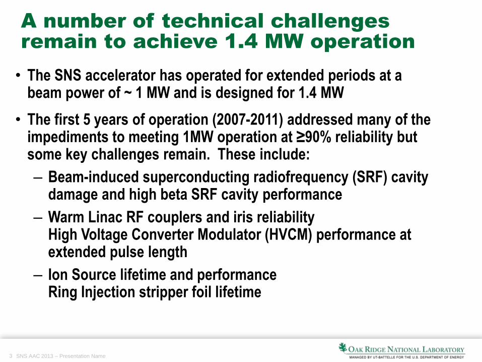
• The SNS accelerator has operated for extended periods at a beam power of ~ 1 MW and is designed for 1.4 MW
• The first 5 years of operation (2007-2011) addressed many of the impediments to meeting 1MW operation at ≥90% reliability but some key challenges remain. These include:
– Beam-induced superconducting radiofrequency (SRF) cavity damage and high beta SRF cavity performance
– Warm Linac RF couplers and iris reliability High Voltage Converter Modulator (HVCM) performance at extended pulse length
– Ion Source lifetime and performanceRing Injection stripper foil lifetime
A number of technical challenges
remain to achieve 1.4 MW operation

4 SNS AAC 2013 – SNS RAD Plan for 1.4 MW Operation
Average Beam
Current (mA)
RF Pulse length
(mS)
Energy (GeV) Power
(MW)
Present 22.8 0.825 0.925 1.0
+ 75 us pulse 22.8 0.900 0.925 1.1
+ 150 us pulse 22.8 0.975 0.925 1.2
Current increase 25.4 0.975 0.925 1.3
Energy increase 25.4 0.975 1.0 1.4
• Pulse Length
• Beam Current
• Beam Energy
Increasing the beam power to the full 1.4 MW design
capability involves increasing three primary
parameters

5 SNS AAC 2013 – SNS RAD Plan for 1.4 MW Operation
Increasing beam power cannot compromise our
other goals – sustainable, high reliability operation
is key to success
FY13 FY14 FY15 FY16 FY17
Plan 1.0MW 1.1MW 1.2MW 1.3MW 1.4MW
Goal FY13 FY14 FY15 FY16 FY17
Total Operating Hours
(Goal)
4500 5000 5200 4500* 5200
Neutron Production
Hours (Goal)
4000 4500 4600 4000* 4600
Neutron Production
Hours (Commitment)
4000 4500 4500 3900* 4500
Reliability
(Commitment)
≥90% ≥90% ≥90% ≥90% ≥90%
The current path towards 1.4MW is shown below and reflects funding
constraints and target supply chain challenges.
Our sponsors expect us to maintain operational performance in
operating hours and reliability
SNS Power timeline at sustained 90% reliability
6 SNS AAC 2013 – SNS RAD Plan for 1.4 MW Operation
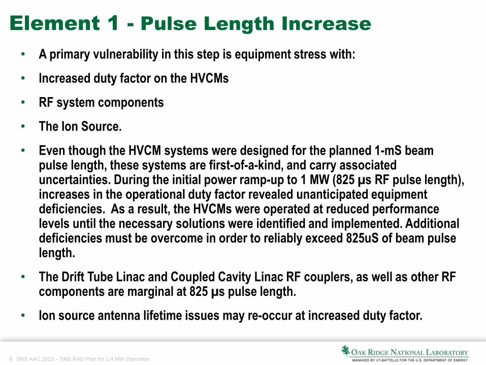
Element 1 - Pulse Length Increase
• A primary vulnerability in this step is equipment stress with:
• Increased duty factor on the HVCMs
• RF system components
• The Ion Source.
• Even though the HVCM systems were designed for the planned 1-mS beam pulse length, these systems are first-of-a-kind, and carry associated uncertainties. During the initial power ramp-up to 1 MW (825 µs RF pulse length), increases in the operational duty factor revealed unanticipated equipment deficiencies. As a result, the HVCMs were operated at reduced performance levels until the necessary solutions were identified and implemented. Additional deficiencies must be overcome in order to reliably exceed 825uS of beam pulse length.
• The Drift Tube Linac and Coupled Cavity Linac RF couplers, as well as other RF components are marginal at 825 µs pulse length.
• Ion source antenna lifetime issues may re-occur at increased duty factor.

7 SNS AAC 2013 – SNS RAD Plan for 1.4 MW Operation
Pulse Length Increase Details - HVCM
Additional modifications to the HVCMs are required to increase the RF pulse length to the 975 µs for 1.4MW. These include:
• Pulse droop reduction – The HVCMs currently run open-loop. The pulses currently droop to below the limit for RF regulation at the full pulse width. This regulation can be achieved with an improved pulse controller.
• Pulse ripple reduction - At full pulse width, the pulse ripple is beyond the ability of the RF control system to compensate. The reduction can be achieved with an improved pulse controller.
• Improved transient over-voltage protection - New snubbers will reduce this leading cause of IGBT failure.
• HVCM Cooling - At present the heat exchangersin the HVCMs are insufficient to dissipate theheat for 975 µs pulse width operation.
• Capacitor lifetime issues (possibly related to overheating).

8 SNS AAC 2013 – SNS RAD Plan for 1.4 MW Operation
• The RF system components that are marginal at 825 µs pulse length will likely have to be improved for reliable 975 µs pulse length operation. These components include the RF couplers for the Drift Tube Linac and Coupled Cavity Linac.
• The Warm Linac vacuum systems are in serious need of an upgrade. They all leak air at some level which leads to degradation of the ion pumps. The ion pumps will be replaced by large turbomolecular pumps.
Pulse Length Increase Details – DTL-CCL

9 SNS AAC 2013 – SNS RAD Plan for 1.4 MW Operation
Pulse Length Increase Details – RFQ
and Ion Source
• The ion source lifetime issues at increased duty factor will need to be
addressed for the internal antenna source. This can be done on the test stand
but further ion source antenna development is needed. We anticipate that the
External Antenna source will play an important part in the upgrade. We will
develop both approaches until the best approach emerges.
• RFQ stable operation at long pulse
length and high current has not been
demonstrated for a long period

10 SNS AAC 2013 – SNS RAD Plan for 1.4 MW Operation
Initially we thought that this would come exclusively from increased current from the ion source. However, a recent evaluation of the RFQ operating parameters revealed that we were not transporting the entire current from the ion source. Evaluations are underway to improve the efficiency of the ion source-RFQ.
Element 2 - Peak Current Increase - Ion
Source and RFQ
The integrated charge from the
BCM02 and BCM11.
The current increased by 25% for
0.4 amplitude from the 0.353 for
production
From the parameter list we were
only looking for ~11% more.

11 SNS AAC 2013 – SNS RAD Plan for 1.4 MW Operation
The SNS beam was designed to operate at 1,000 MeV with an energy reserve of 25 MeV.
• The beam is currently operating at 937 MeV with minimal reserve. A 6.3% beam energy increase is required to reach 1.4 MW reliably, and an additional 2.5% increase is required to provide the desired energy reserve.
Element 3 – Beam Energy Increase (1)

12 SNS AAC 2013 – SNS RAD Plan for 1.4 MW Operation
• The achievable operating gradients in the high beta SRF cavities are lower than the design value, mainly due to the heating effect by electron emission and damaged parts/sub-equipment in the cryomodules. To reach the design output energy with an energy reserve more than 25 MeV, a ~15% increase in the average field gradient of the High Beta SRF cavities is needed.
• The preferred path to achieve and maintain the increased gradient is to develop and implement an in-situ processing surface treatment to reduce electron activity, which will address mild surface contamination or imperfection.
• In-situ plasma processing is one of the most promising solutions based on preliminary studies done in 2009 at SNS. This is a new technique that requires some R&D to optimize the processing parameters.
• If the R&D produces an applicable solution for the in-situ processing, it will take about 2 years to accomplish in-situ processing of cavities in the accelerator tunnel.
Element 3 – Beam Energy Increase (2)

13 SNS AAC 2013 – SNS RAD Plan for 1.4 MW Operation
Plan by Year
FY 2013
• Operate with high reliability at 1.0MW – subject to Target supply limitations [key recent decision to remain at 0.85 MW for foreseeable future to conserve spare target(s) and minimize target changes]
• Demonstrate current increase with higher operating power on RFQ and retune RFQ
• Execute a several week run at the end of the Spring-Summer operating cycle at 1.1MW [deferred until target spare situation improves]
• HVCM Improvements
• Prototype Cooling System Upgrade
• Complete Snubber deployment
• Develop Controller
• Develop External Antenna Ion Source
• Begin design of new RF Couplers
• Develop Plasma Processing – R&D with 3 cell cavity

14 SNS AAC 2013 – SNS RAD Plan for 1.4 MW Operation
Plan by YearPlan by Year
FY 2014
• Operate with high reliability at 1.1MW
• HVCM
• Deploy HVCM Cooling Upgrade
• Test Prototype Controller
• Develop External Antenna Ion Source
• Prototype and test new RF Couplers
• Develop Plasma Processing – R&D with 6 cell cavity and HTA
• Execute a several week run at the end of the Spring-Summer operating cycle at 1.2MW

15 SNS AAC 2013 – SNS RAD Plan for 1.4 MW Operation
Plan by YearPlan by Year
FY 2015
• Operate with high reliability at 1.2MW
• HVCM
• Deploy New Controller
• Test External Antenna Ion Source
• Fabricate and install new RF Couplers
• Develop Plasma Processing – R&D with full Cryomdule

16 SNS AAC 2013 – SNS RAD Plan for 1.4 MW Operation
Plan by YearPlan by Year
FY 2016
• Operate with high reliability at 1.2MW and begin to operate at 1.3MW
• HVCM
• Deploy New Controller
• Test External Antenna Ion Source
• Fabricate and install new RF Couplers
• Deploy Plasma Processing of in-situ Cryomodules

17 SNS AAC 2013 – SNS RAD Plan for 1.4 MW Operation
Plan by YearPlan by Year
FY 2017
• Operate with high reliability at 1.3MW and begin to operate at 1.4MW
• HVCM
• Complete HVCM Upgrades
• Operate with External Antenna Ion Source
• Complete fabrication and installation of new RF Couplers
• Complete Plasma Processing of in-situ Cryomodules

18 SNS AAC 2013 – SNS RAD Plan for 1.4 MW Operation
Element 4 - Address Beam Stability,
Injection Region and Sustainability concerns

19 SNS AAC 2013 – SNS RAD Plan for 1.4 MW Operation
UpgradeFY13 FY14 FY15 FY16 FY17 Total
($K) ($K) ($K) ($K) ($K) ($K)
HVCM 408 1220 400 400 0 2428
Cryo Test Facility 1148 600 200 0 0 1948
Medium Beta Spare
Cryomodule0 0 1500 1500 3000
Cryomodule
Rework-Processing250 250 950 550 550 2550
Ring systems 0 0 536 204 536 1276
Warm Linac
Vacuum 0 0 450 450 900
Primary Stripper
Foil 0 0 0 1,000 0 1000
TOTAL $1,806 $2,070 $2,536 $4,104 $2,586 $13,102
Operations
Funding $250 $250 $950 $2,050 $2,050 $5,550
AIP Funding $1,556 $1,820 $1,586 $2,054 $536 $7,552

20 SNS AAC 2013 – SNS RAD Plan for 1.4 MW Operation
Summary
• Path forward is technically clear and well-defined, and must be accomplished within allocated operating budgets and AIP funding
• We are ready to demonstrate sustained operation at 1.1MW
• Key limitations on progress are
• Directorate funding distribution
• Target supply chain
• Positioned to execute the plan describe above – estimated completion in FY17 if we can resume high-power operation in the Summer of 2014
• Incremental increases in power as different elements are completed and consistent with a conservative, sustainable approach to operation that supports sponsor requirements