SNOWMOBILE ASSEMBLY& PREPARATION MANUAL Brake Light .. ..... ... snowmobile from the skid. ... 1....
21
SST SB340-A1 SB440-A1 SNOWMOBILE ASSEMBLY& PREPARATION MANUAL
-
Upload
nguyenhanh -
Category
Documents
-
view
224 -
download
3
Transcript of SNOWMOBILE ASSEMBLY& PREPARATION MANUAL Brake Light .. ..... ... snowmobile from the skid. ... 1....

SST SB340-A1 SB440-A1
SNOWMOBILE ASSEMBLY&
PREPARATION MANUAL

Notice to Dealers
This manual is provided to ensure that the snowmobile is assembled correctly and given proper presale preparation . Your customer expects and deserves a safe, reliable snowmobile, and performance of the steps listed here is essential to that end.
The selling dealer assumes sole responsibility for any unauthorized modifications prior to sale. Refer to your Service Binder for any Service Bulletins specifying Factory Directed Modifications (Special Claims) which must be performed before the snowmobile is ready for sale .
SAFETY AWARENESS
I WARNING I THIS WARNING SYMBOL IDENTIFIES SPECIAL INSTRUCTIONS OR PROCE DURES WHICH, IF NOT CORRECTLY FOLLOWED, COULD RESULT IN PERSONAL IN JURY, OR LOSS OF LIFE.
THIS CAUTION SYMBOL IDENTIFIES SPECIAL INSTRUCTIONS OR PROCEDURES WHICH, IF NOT STRICTLY OBSERVED, COULD RESULT IN DAMAGE TO, OR DESTRUCTION OF EQUIPMENT.
Whenever you see the symbols shown above, heed their instructions! Always follow safe operating and maintenance practices.
~J

Table of Contents Assembly & Preparation .. ...... .... .... .. ....... ......... ... ....... ...... ..... .. .. ... ......... ......... .... ................ ........ 2
Uncrate ... ... ... ..... ... ... ... ... ......... .... ..... .... ..... ...... .. .......... ...... ... ..... ...... .... .. .. ............... ... ........ ... .. 2 Handlebar ....... .... ...... .... .. ... .. .... .. ..... ... .. ... .... ..... ... ....... ... .... .... .. .... ... .. ... .... ... ... ........ .. ... .... .. ...... 2 Suspension ........ ... ........ ....... .. ....... ... .... .. ... ... ... ...... .. ..................... .... ........ ... ... ..... .. ... .. .... .. .... .. 2 Skis .. ....... ...... .. ....... ...... .. ..... .. ....... ............ ... ......... ... ........ ........ .. ..... ..... .......... .. ....... ........ .... .... 3 Headlight .... .. ... ... .. ... ... ..... .. .. ..... ... .. .... .. ........ ... ..... ... ..... ............. .... ... .......... .... ......... .. ............. 4 Windshield .. .... ...... ... ........ ........ ..... ..... ... .... .. ... ... ..... ...... ..... .. .. .. ....... .. ... .... .... ... ........ .......... .... . 5 Tool Kit / Owner Manual .. ........ .. ......... ........ ........................... ........ ....... .... ....... ....... .. .... ....... 5 Safety Labels .. .... .. .. .. .. .... ..... ..... ... ... ... .... . ... ... ... ..... ... . ......... .... ...... .... .. .. . ... .. ..... .. .. ..... .. ... . .. .. ... 5 Clutch A lignment .. ... ... .... .... ... .... .... ... ....... ... ..... .... ... ...... .. ...... ... .. ...... ..... .. .. ..... ... .. ...... .. ......... 6 Clutch Center Distance ... .............. .. ........... ....... .......... ...... ...... ...... .. .... ... ..... .. ... .. .... ..... ...... .. 6 Dr ive Chain ..... .... .... .... .... .. .. ............ ... ........ ... .. .... ... ... ..... ....... .... ..... ...... .... ..... ....... ... .... ...... .... 6 Chaincase ....... ....... .. .. .. ... ...... ... .......... ... ... .... ..... ............ ........ ........ ......... ....... .... .......... ..... ...... 7 Brake ...... ......... .... .. ... ................... ....... .... ...... .. ... ........ ..... ... .... .. ...... .. ... .... .. , ........ .... ..... ....... .... . 7 Circuit Board ...... ... ... ... .. ......... ..... ...... .... ... .. ... .. ..... ........ .... ... ... .. ... .. .. ..... ....... ............. ........... .. 8 Enrichener Control .......... ..... ........ ... ..... .... ......... .. . .. ........ ..... .. ...... ........ ....... ... ... .... ... ...... ... ... . 8 Throttle" Cable .... ... ... ...... ...... . ...... .. .. .... ... ......... ... .... ..... ... ... .. ..... ............... ...... ... ... ..... .... ......... 9 Carburetor Adjustments ..... ... ........ .. .. .... ...... .. .. .... .... ..... .... .......... .. .... .... .... .... ... ... .... ... .......... 9 Ignition Timing Procedure ... .... .. ..... .... ..... ... .... .. ... ... ....... .. ........ ... ... ... .......... .......... ......... .... 10 Spark Plugs ......... ..... .................... ... .. .. ... ... ... ... ...... .. ..... ... .. ....... .... ......... ........ ......... ... ..... . ' .. 10 Lubrication .... ......... ................ .... .. ... .... .. ..... ... ........ .... ... ... ....... ... ..... .. .... ... .. .. .. ... ..... ... ... ... . .... 11 Fuel Mix ........ ... ... ... .... .... ...... ....... .... .... ..... ..... .... .... ... .... ..... .. ....... ..... .. ... .. ....... ..... .... ... ...... .... 12 Headlight Adjustment .. ... ... ... ... ..... .. .. ... .. ..... .. ...... .... .. ....... ...... ..... ... ... ........ .. ...... ... ....... ... ... . 12 Tail / Brake Light .. ..... ..... ... ...... ... .... ......... .. ... ........ .. ... .... ... ... ...... ...... .. .. ....... .. .. ... ...... ..... ...... . 13 Track Adjustments .. ... .......... .. .. ... ........ ... ... ... ..... ........ .. ..... .... ........ .... .. .... .... ..... .... .... ..... .... .. 13
Test Ride (Operat ional Checks) .. ........ .. .... .......... ... .... ..... .... .. ....... ..... .... .... ....... .. ............. ...... .. 15 Specifications ..... .. ... . ..... .. ..... ............. .. ... .... .. ...... ......... . .... ...... ... .... .. ............. ... ........... ... ..... ... ... . 16
Engine .. ... .... .. ....... .. ............. ... ..... ... ..... ......... ........... ..... .... ..... .. .. ...... ... .. ... ... .......... ....... .. .... ... 16 Carburetor Settings ... .. ... ... ....... ... .... .. ...... ... .. ... ...... ... .... ........ .... .... ... ... ........ ... ... ...... ........ .. .. 16 Fuel .... ... .... ......... .. ... .. ....... .... ....... .......... .. ...... ................. .. ....... .... ... ... .. ........ .. ... .. ..... .... ........ . 16 Drive System ...... .... ....... .. .. .. .. ..... .... .... ..... ... ... ... ... ... ..... ..... .. .. ..... .. . .. ... ... ... . .. .. .. ... .. ..... . .... ..... 16 Electrical System .... ...... .. ..... .. ... .......... .. .. ... .... .. ...... ... .. .... ..... ....... .. ... .. ..... ........... .. ...... .... .... . 16 Torque Chart .. .. ... .. ..... .. .......... .. ... .. .... .... .. ..... ..... ...... ... .... .. ..... ..... ... ... ... ...... .. ....... ..... .... .. ... ... 16
TABLE OF CONTENTS 1

Assembly & Preparation Uncrate
Remove the top and end panels from the carton. Unbolt the skis, then remove the side panels. See Figure 1 .
Unscrew the nuts securing the ski spindles to the skid. See Figure 2.
1. Ski Spi ndle
WARNING'
To prevent personal injury, use lifting equipment with approved safety hooks . when raising the snowmobile.
2 ASSEMBLY & PREPARATION
With assistance, or the use of a hoist, carefully liftthe snowmobile from the skid. Thoroughly inspect the snowmobile for shipping damage and missing parts.
Handlebar
Adjust the handlebar for a comfortable driving position and evenly torque the four Allen screws to 7 to 9 foot pounds (1 .0 to 1.2 kg-mI. See Figure 3.
1. Cutaway Section of Hood
Check the routing of the cables and wire harnesses for proper positioning . They should pass through the cutaway section in the hood to provide adequate free movement when the hood is closed. See Figure 3.
Suspension
The snowmobile is shipped with the suspension spri ngs disconnected from the front and rear suspension arms. See Figure 4.
1. Front Suspension Arm 2. Rear Suspension Arm '
? }

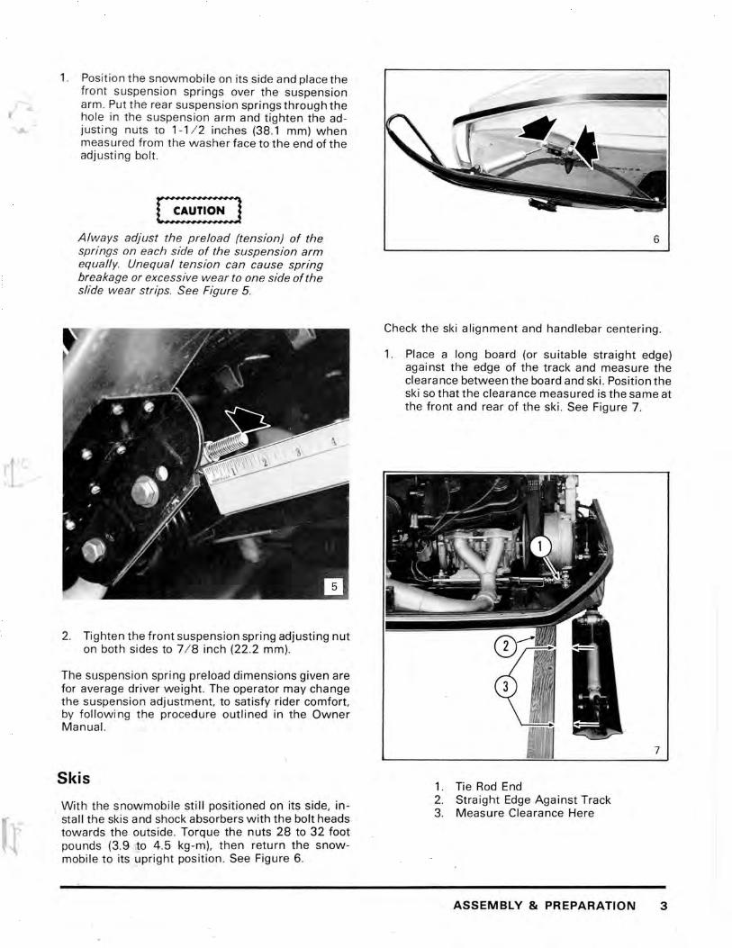
1. Position the snowmobile on its side and place the front suspension springs over the suspension arm. Put the rear suspension springs through the
r hole in the suspension arm and tighten the adjusting nuts to 1-1 / 2 inches (38 .1 mm) when measured from the washer face to the end of the adjusting bolt .
Always adjust the preload (tension) of the springs on each side of the suspension arm equal/y. Unequal tension can cause spring breakage or excessive wear to one side of the slide wear strips. See Figure 5 .
2. Tighten the front suspension spring adjusting nut on both sides to 7 / 8 inch (22 .2 mm).
The suspension spring preload dimensions given are for average driver weight . The operator may change the suspension adjustment, to satisfy rider comfort, by fol/owing the procedure outlined in the Owner Manual.
Skis
With the snowmobile still positioned on its side, in-. stall the skis and shock absorbers with the bolt heads
towards the. outside. Torque the nuts 28 to 32 foot pounds (3.9 to 4 .5 kg -m), then return the snowmobile to its upright position. See Figure 6.
6
Check the ski alignment and handlebar centering.
1. Place a long board (or suitable straight edge) against the edge of the track and measure the clearance between the board and ski . Position the ski so that the clearance measured is the same at the front and rear of the ski . See Figure 7 .
7
1. Tie Rod End 2. Straight Edge Against Track 3. Measure Clearance Here
ASSEMBLY & PREPARATION 3

Be sure the ski remains parallel tothe straight hile turning the tie rod end adjusting bolt.
eck the handlebar for centering. If centering is ::juired, loosen the lock nuts and turn the tie rod ld adjusting bolt to center the handlebar. See gure 7.
WARNING t If the dimension shown exceeds 1-1 / 4 inch (32 mm). reposition the steering arm on the ski spindle as necessary to reduce the dimension and prevent possible steering linkage failure. See Figure 8.
1. Tie Rod End Adjusting Bolt 2. Locknuts 3. 1-1 14 Inch (32 mm) Maximum
3. To align the other ski, move both ski tips towards the center of the snowmobile to remove the steering linkage play. Turn the tie rod end adjusting bolt (located below the muffler) to obtain equal distance from sk i to ski when measured at the front and rear of the skis. See Figure 9.
4. Torque all the hardware (nuts, bolts, etc.) in the steering system. Refer to the torque chart for the recommended values.
4 ASSEMBLY & PREPARATION
9
Headlight
Secure the headlight to the hood with the bolts, flat washers, and lockwashers provided. Route the headlight wire harness through the retaining clamps, and position the wire harness so it will not be pinched when the hood is closed. See Figure 10.
-________ 10
1. Retaining Clamps 2. Headlight Connector 3. Adjusting Screws
1. Posit ion the snowmobile on its side and place the front suspension springs over the suspension arm. Put the rear suspension springs through the
r hole in the suspension arm and tighten the adjusti ng nuts to 1-11 2 inches (38.1 mm) when measured from the washer face to the end of the adjust ing bolt.
Always adjust the preload (tension) of the springs on each side of the suspension arm equal/y. Unequal tension can cause spring breakage or excessive wear to one side of the slide wear strips. See Figure 5.
2. Tighten the front suspension spring adjusting nut on both sides to 7 / 8 inch (22.2 mm).
The suspension spring preload dimensions given are for average driver weight. The operator may change the suspension adj ustment, to satisfy rider comfort, by following the procedure outlined in the Owner Manual.
Skis
With the snowmobile still positioned on its side, in-. stall the skis and shock absorbers with the bolt heads
towards the outside. Torque the nuts 28 to 32 foot pounds (3.9.to 4 .5 kg-m), then return the snowmobile to its upright position. See Figure 6.
6
Check the ski alignment and handlebar centering .
1. Place a long board (or suitable straight edge) against the edge of the track and measure the clearance between the board and ski. Position the ski so that the clearance measured is the same at the front and rear of the ski. See Figure 7.
7
1. Tie Rod End 2. Straight Edge Against Track 3. Measure Clearance Here
ASSEMBLY & PREPARATION 3

NOTE: Be sure the ski remains parallel to the straight edge while turning the tie rod end adjusting bolt.
2. Check the handlebar for centering. If centering is required, loosen the lock nuts and turn the tie rod end adjusting bolt to center the handlebar. See Figure 7.
WARNING'
If the dimension shown exceeds 1-1/4 inch (32 mm), reposition the steering arm on the ski spindle as necessary to reduce the dimension and prevent possible steering linkage failure. See Figure 8.
1. Tie Rod End Adjusting Bolt 2. Locknuts 3. 1-1/ 4 Inch (32 mm) Maximum
3. To align the other ski, move both ski tips towards the center of the snowmobile to remove the steering linkage play. Turn the tie rod end adjusting bolt (located below the muffler) to obtain equal distance from ski to ski when measured at the front and rear of the skis. See Figure 9.
4. Torque all the hardware (nuts, bolts, etc.) in the steeri ng system. Refer to the torque chart for the recommended values.
4 ASSEMBLY & PREPARATION
9
Headlight
Secure the headlight to the hood with the bolts, flat washers, and lockwashers provided . Route the headlight wire harness through the retaining clamps, and position the wire harness so it will not be pinched when the hood is closed. See Figure 10.
-
_________ 10
1. Retaining Clamps 2. Headlight Connector 3. Adjusting Screws

To provide adequate clearance for installation of the headlight harness connector, turn the four headlight adjusting screws until the headlight lens contacts the rim at the front of the housing . See Figure 10.
Remove the bulb from the lens and install the wire harness connector onto the terminals. Insert the bulb and connector assembly into the headlight lens and secure the bulb with the retaining ring.
Windshield
Remove the protective film and install the windshield with the fasteners provided. See Figure 11 .
Tool Kit/Owner Manual
Check the storage bag to be sure it contains the Tool Kit and Owner Manual.
Safety Labels r-I-W-A-R-N-.-N-G-',
Insure that all safety decals are properly located and secure. See Figure 12.
12
ASSEMBLY & PREPARATION 5

Clutch Alignment
The clutch alignment (offset) should be 0.454 inch (11.5 mm) as measured from the back face of the fixed pulley on the drive clutch to the edge of the driven clutch moveable pulley. See Figure 13.
13
1. Fixed Pulley on Drive Clutch 2. Moveable Pulley on Driven Clutch
If adjustment of the clutch alignment is required, loosen the bolts securing the engine to the mounting frame, and sl ide the engine left or right as necessary to obtain the 0.454 inch (11.5 mm) offset . Tighten the engi ne mou nt bolts.
Clutch Center Distance
The clutch center distance should be 10.3 inches (262 mm). See Figure 14.
If adjustment of the clutch center distance is re quired, loosen the four mounting nuts on the chaincase and the lock nut for the adjusting setscrew. The driven clutch support arm must be disconnected from the chassis by removing the clevis pin from the yoke. While pushing forward on the chaincase, turn the setscrew as required to obtain 10.3 inch (262 mm) center distance. Tighten
6 ASSEMBLY &PREPARATION
the locknut and the chaincase mounting nuts. See Figure 15. Install the driven clutch support arm to the chassis and secure the clevis pin with safety clip.
1. Locknut 2. Setscrew 3. Mounting Nuts
Drive Chain
Drive chai n tension is correct when the driven clutch pulley outer edge can be freely turned 3/8 to 1/2 inch (9.5 to 12.7 mm). See Figure 16.
~J

,
1. 3/ 8 to 1 I ? Inch (9 .5 to 12.7 mm)
If adjustment of the chain tension is required, proceed as follows:
1. Loosen the locknut and setsc rew, then rotate the driven clutch pulley towards the front of the snowmobile to allow the chain to be properly tensioned.
2. Turn the adjustment setscrew until it is tight and tighten the locknut.
Chaincase
NOTE: Use the Sno'" Jet Chain Lubricant provided when filling the chaincase .
Remove the upper plug in the chainC' '"' se cover and pour the ent ire can of lubricant into 3 chaincase. This provides the proper lubricant level for the chain and bearings. See Figure 17.
Brake
Check the brake adjustment to be sure the driven clutch can be moved back and forth with just a very slight brake drag on the brake disc and that the brake lever movement is less than 3 / 4 inch (19 mm) when applying the brake. See Figure 18.
WARNING'
DO NOT OVERTIGHTEN the brake because damage to components, or personal injury could result
ASSEMBLY & PREPARATION 7

If brake adjustment is required, turn the adjusting nut while simultaneously moving the driven clutch back and forth until the brake pads just begin to move with the disc. See Figure 19.
1. Brake Adjusting Nut 2. Brake Disc 3. Brake Pads
Circuit Board
Check the connectors on the wiring panel circuit board to be sure they are properly located and secure . The circuit board identifies the wire harness and connector color that should be attached to the ter minals. See Figure 20.
8 ASSEMBLY & PREPARATION
1. Wire Harness 2. Connector Color 3. Lighting System Regulator
Enrichener Control
With the enrichener lever at off, the outer casing of the enrichener cable should have 1/ 16 inch (1 .5 mm) of free movement when raised . See Figure 21 .
1. 1/ 16Inch(1.5mm) 2. Locknut 3. Adjusting Screw
, lj,

~-
NOTE: Engine flooding may occur if the enrichener cable free movement is less than 1/ 16 inch (1.5 mm).
If adjustment of the enrichener cable is required, loosen the locknut and turn the adjusting screw to obtain the correct clearance.
Throttle Cable
[:~~~!!~~] If a gap between the throttle lever and handlebar grip is present when the lever is at full throttle, excessive stress may be placed on the throttle cable ends which could cause cable failure.
With the air silencer removed from the carburetor, hold the throttle lever at the full throttle position and check that:
1. The throttle slide inside the carburetor bore opens fully.
2. The throttle lever is tight against the handlebar grip.
If adjustment of the throttle is required, loosen the lockn ut, and turn the" adjusting screw on the throttle cabl e as required, and tighten the locknut. See Fig ure 22.
1. Locknut 2. Adjusting Screw
Carburetor Adjustments
Air Screw
The carburetor air screw is properly adjusted when opened 1.5 to 2 turns off its seat. Refer to the spec ifi cations pa{le and see Figure 23.
1. Air Screw 2. Idle Screw 3. Power Jet Metering Needle
Idle Screw
The idle speed screw initial adjustment is 3 to 6 turns open from coil bound, (screw turned in tight), refer to the specifications page. Use a tachometer and adjust the engine idle speed to 2,000 R.P.M. See Figure 23.
Power Jet Metering Needle
Turn the cover on the power jet needle so the tab is straight down (6 o'clock position). See Figure 23.
Make sure the fuel pump pulse line and all the fuel lines are secure and free of kinks or sharp bends.
ASSEMBLY & PREPARATION 9

Ignition Timing Procedure
1. Remove both spark plugs and install a dial indi cator in the spark plug hole on the right hand side of the engine.
2. Remove the manual starter, starter pulley, and flywheel cover.
3. Rotate the engine to Top Dead Center and adjust the dial indicator to zero . See Figure 24.
CD
24
1. Dial Indicator
4 . Turn the flywheel counterclockwise until the dial indicator reads 0 .063 inch (1 .6 mm) before T.O.C. and check the timing marks on the flywheel and pulser coil. The timing marks should be aligned . See Figure 25.
5. If adjustment of the timing marks is required, loosen the two screws securing the pulser coil and position the pulser mark to line up with the flywheel mark while the piston is located 0.063 inch (1 .6 mm) B.T.O.C.
10 ASSEMBLY & PREPARATION
1. Mark on Flywheel 2. Mark on Pulser Co il
6. Repeat the timing procedure for the left hand cylinder. The difference in ignition timing between the two cylinders should be zero .
Spark Plugs
Adjust the spark plug gap to 0.020 to 0 .024 inch (0.5 to 0 .6 mm). See Figure 26.
26
1. Gap 2. Washer
,1

Befo re installing the spark plugs, be sure the washer is insta lled and the seat on the cylinder head is clean. Install the spark plug and torque it to 18 to 20 foot pounds (2.5 to 2.8 kg-m).
Lubrication
If required, lubricate the suspension arms and steering column with a low temperature E.P. (extreme pressure) grease. See Figures 27 and 28.
Excessive grease applied to the front axle bearing may cause the seal to be pushed out of the end cap resulting in possible bearing damage.
With a hand operated grease gun, apply three pumps of grease into the fitting on the axle bearing end cap . See Figure 29.
29
1. Grease Fitting 2. Axle Bearing End Cap 3. Seal
ASSEMBLY & PREPARATION 11

Fuel Mix
Fuel and oil MUST be PROPERL Y MIXED or damage to the engine will result.
Th e recommended fuel mix ratio is 25 to 1. Add one quart (0.94 liters) of B.IA certified T.C.W. oil to 6 .25 gallons (23.6 liters) of gasoline, with a minimum pump posted octane number of 89, and thoroughly mix the fuel and oil by shaking the can from side to side. See Figure 30.
30
Start the engine and run it at low speed for 3 to 5 minutes to provide proper engine warm -up.
I WARNING t Engine idle speed is 2,000 R.P.M. If the idle speed is adjusted too fast. the drive clutch may not disengage when the throttle lever is released, or the clutch may automatically engage when the Enrichener lever is used during starting. Either condition could result in personal injury.
Adjust the engine idle speed to 2,000 R.P.M . by turning the idle speed screw on the carburetor.
12 ASSEMBLY & PREPARATION
Headlight Adjustment
1. Position the snowmobile on a level floor so the headlight points at a wall 25 feet (7,620 mm) away.
2. M easure the distance from the floor to the center of the headlight and mark the wall at the dimension measured (reference mark). See Figure 31 .
2
-- - - - - - - -- --~- CD
31
1. Wall 2. 25 Feet (7,620 mm) 3. Reference Mark center of headlight to floor) 4. 2 Inches (51 mm) Below Reference Mark
WARNING'
If adjusting the headlight indoors, provide proper ventilation to prevent possible carbon monoxide poisoning.
NOTE: Be sure an operator is seated on the snowmobile while the engine is running to prevent the vehicle from creeping ahead, and to assure proper aiming .
3. Turn on the headlight high beam . The headlight is properly aimed when the high beam is centered and aimed 2 inches (51 mm) below the reference mark on the wall. See Figure 31 .
!
1
~J t
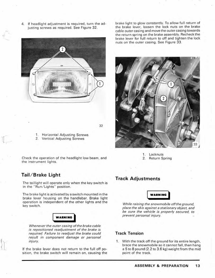
4. If headlight adjustment is required , turn the ad justing screws as required. See Figure 32.
32
1. Horizontal Adjusting Screws 2. Vert ical Adjusting Screws
Check th e operation of the headlight low beam, and the inst rument lights.
Tail/Brake light
The taillight w ill operate only when the key switch is in the "Run/ Lights" position.
The brake light is activated by a switch mounted in the brake lever housing on the handlebar. Brake light operat ion is independent of the other lights and the key switch.
WARNING'
Whenever the outer casing of the brake cable is repositioned readjustment of the brake is required. Failure to readjust the brake could result in component damage or personal Injury.
If the brake lever does not return to the full off posit ion, the brake switch w i ll remain on, causing the
brake light to glow constantly. To allow full return of the brake lever, loosen the lock nuts on the brake cable outer casi ng and move the outer casi ng towards the return spri ng on the brake assembly. Recheck the brake lever for full return to off and tighten the lock nuts on the outer casing . See Figure 33 .
1. Locknuts 2 . Return Spring
Track Adjustments
WARNING'
While raising the snowmobile off the ground, place the skis against a stationary object, and be sure the vehicle is properly secured. to prevent personal injury.
Track Tension
1. With the track off the ground for its entire length, brace the snowmobile so it cannot fall, then hang a 5 to 8 pound (2 .2 to 3.6 kg) weight from the mid poi nt of the track .
ASSEMBLY & PREPARATION 13

2. The clearance from the bottom of the wear strip to the top of the track should be 3 / 4 inch (19 mm) when measured directly below the shock absorber upper mount bolt. See Figure 34.
1. 3/ 4 Inch (19 mm) 2. Shock Absorber Upper Mount Bolt
3. If necessary, turn the rear axle adjusting bolts as required to obtain the specified wear strip-totrack clearance . See Figure 35 .
4. When the proper tension is attained, be sure both adjusting bolts are the same length when measured from the bolt head to the rear axle bracket . See Figure 35.
14 ASSEMBLY & PREPARATION
1. Rear Axle Adjusting Bolts 2. Lock (Jam) Nut
Track Alignment
I WARNI NG'
To prevent Injury, never measure track alignment while the engine is running.
Remove the weight from the track, start the engine and push the throttle only enough to turn the track slowly a few revolutions, then stop the engine and check the alignment.
The track is aligned when the distance between the rear idler wheel and edge of the track is equal on both sides. See Figure 36.
If the track runs to one side, tighten the rear axle adjusting bolt on the same side, approximately 1 / 2 turn, then restart the engine and recheck the alignment.
l

• STEERING
.r Steering should be smooth and free from lock -to lock with no excessive looseness in the steering linkage.
• ENGINE
Recoil starter works properly and the engine starts promptly. Test for good throttle response and return.
• SUSPENSION
Adjusted for average driver weight and operates smoothly .
• EMERGENCY STOP SWITCH
Check operation in all switch positions.
• CLUTCHES
36 Test for smooth operation and correct engine '---__________________ J R.P.M. (7,000) at full throttle.
1. Idler Wheel 2. Edge of Track 3. Dimension Equal On Both Sides
When track alignment is correct, tighten the lock nut on both rear axle adjusting bolts.
Test Ride (Operationa l Checks) Test ride the snowmobile and check forthe following:
• CONTROL CABLES
The throttle and brake controls must operate w ithout binding and return freely in any steering position .
• BRAKES
When activated, the brakes should result in adequate smooth stopping of the track; when re leased, there should be no brake drag.
• INSTRUMENTS
Check for proper indications.
During the test ride, listen for any unusual noises (rattles, squeaks, etc.) that may warrant inspection and correction .
When the test ride is completed , open the hood and thoroughly inspect the engine compartment for fue l or oil leaks.
TEST RIDE (OPERATIONAL CHECKS) 15
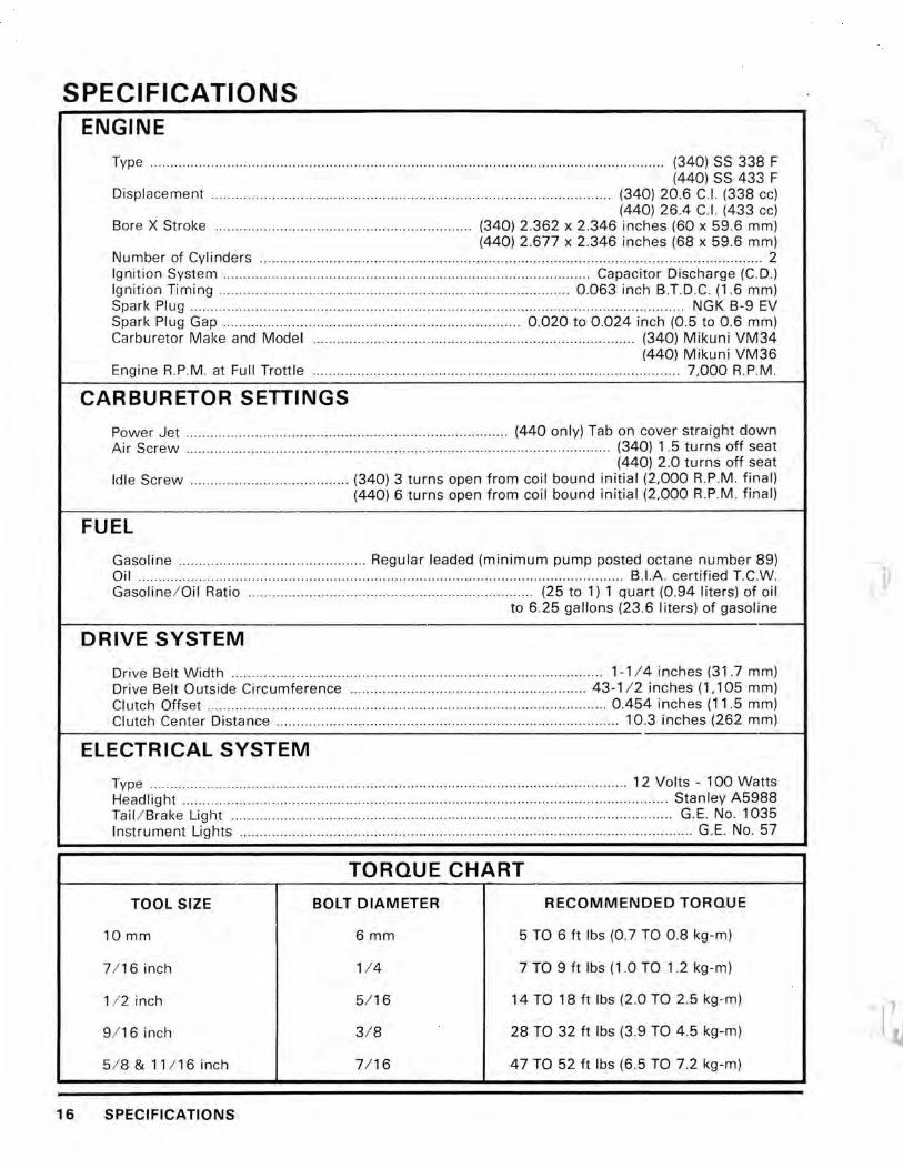
SPECIFICATIONS
16
ENGINE
Type .... ........ .... ... ....... ........... ....... .. ...... ...... .. ... ....................................... .............. ........ .. (340) SS 338 F (440) SS 433 F
Displacement .. ... ... .. ...... .. ........ ... ...... ...... ............ ... .......... ..... ..... ........ .............. (340) 20.6 C.1. (338 cc) (440) 26.4 C.I. (433 cc)
Bore X Stroke .... ...... ......... .. ...... ....... .. ........ ................... (340) 2 .362 x 2.346 inches (60 x 59.6 mm) (440) 2.677 x 2 .346 inches (68 x 59.6 mm)
Number of Cylinders .. ... .......... .... ..... ... .. .. ... ...... ........ ..... ...... .... ... ...... ... .. ..... ....... .... ..... ........... ..... .. .. ..... 2 Ignition System .. ... .... ....................... ... .. ............. .. .............. .. ...................... Capacitor Discharge (C. D.) Ignition Timing ......... .... .. ................ .... .... ..... .... .... .. .. ....... .. ...... .... .... ...... . 0.063 inch B.T.D.C. (1.6 mm) Spark Plug ............ ........ .. .. .............. .... ...... ... ....................... .. ... ..... ..... .... ... .... .............. ..... .. NGK B-9 EV Spark Plug Gap .. .. ............ .......... ............. .. ...... .. .... ........ ............ 0.020 to 0 .024 inch (0.5 to 0 .6 mm) Carburetor Make and Model ............. .. .. ........... ....... ........ ....... .. ... ........ ..... .. .. ...... . (340) Mikuni VM34
(440) Mikun i VM36 Engine R.P.M. at Full Trottle .......... .. ... ............... ............... ........................ ...... ..... ...... .... 7,000 R.P.M.
CARBURETOR SETTINGS
Power Jet ..... ...... .. .. .. ................... .... .... .. .. .... ........................... (440 only) Tab on cover straight down Air Screw .. ................ ..... .. ....... .... .. ...... ...... .. .. ...... .. ...... ...... .. .. .... .. ........ ..... .. ... .. (340) 1.5 turns off seat
(440) 2 .0 turns off seat Idle Screw .. .. .... ...... ... ....... .. ....... .... .. (340) 3 turns open from coil bound initial (2,000 R.P.M . final)
(440) 6 turns open from coil bound initial (2,000 R.P.M . final)
FUEL
Gasoline .......... .... ............. .. ... ........ ...... Regular leaded (minimum pump posted octane number 89) Oil ... ..... ..... .................... ............ .... ................ ..... ... ... .. .... .................. .... ..... ...... .... B.I.A. certified T.C.W. Gasoline/ Oil Ratio ...... ....... ...... ....... .. ............ .... ..... .... .. ............... (25 to 1) 1 quart (0.94 liters) of oil
to 6.25 gallons (23 .6 liters) of gasoline
DRIVE SYSTEM
Drive Belt Width ......... ............ ...... .... .......... ...... ...... .... .. ......... .. .. ... ........ ........ 1-1/4 inches (31 .7 mm) Drive Belt Outside Circumference .... .... ....... .. ..... .. ............... .. .......... .... ... 43-1 / 2 inches (1,105 mm) Clutch Offset ....... .. ... ..................... .. .......... ............ ....... .. .. .......... ................... . 0.454 inches (11.5 mm) Clutch Center Distance .. .... .... .... ...... ........ ..... ........ ................ .... ............... .. ...... 10.3 inches (262 mm)
ELECTRICAL SYSTEM
Type .... .... ... .... .... .......... .... ....... .... .. ..................... ............. ........ .............. ..... ....... ... 12 Volts - 100 Watts Headlight .................. .... .. ..... .. ... ........ ... .... ... ...... ............. ... .... ................. ...... .... .............. Stanley A5988 Tail / Brake Light ........... ...... ....... .. .. ... ......... ........ ........ ................... .. ...... ..... ... ........ .. .. .. ... G.E. No. 1035 Instrument Lights .... .... ..... .... ..... ..... ........ .... ............ ..... ... .. ..... ........ .... .... .. ...... ... .... ....... ...... . G.E. No. 57
TORQUE CHART
TOOL SIZE BOLT DIAMETER RECOMMENDED TORQUE
10 mm 6 mm 5 TO 6 ft Ibs (0.7 TO 0.8 kg-m)
7/ 16 inch 1/ 4 7 TO 9 ft Ibs (1 .0 TO 1.2 kg-m)
1/ 2 inch 5/ 16 14 TO 18 ft Ibs (2 .0 TO 2.5 kg -m)
9/ 16 inch 3/ 8 28 TO 32 ft Ibs (3 .9 TO 4 .5 kg-m)
5/ 8&11 / 16inch 7/ 16 47 TO 52 ft Ibs (6.5 TO 7 .2 kg-m)
SPECIFICATIONS
l~

t
HEADLIGHT
PRINTED CIRCUITRY------1 BOARD
7
TAIL/ STOP LIGHT ASSEMBLY
TACHOMETER
SPEEDOMETER
6
ENGINE
IGNITION
THROTILE CONTROL
COLOR
2
4
LIGHT REGULATOR ASSEMBLY
NO DESCRIPTION
1. BLACK 2. WHITE 3. RED 4. YELLOW 5. BLUE 6. BROWN 7. GREEN 8. LIGHT GREEN 9. TAN
10. GRAY 11. ORANGE 12. BLACK-WHITE
17