snorr/ece4501s2/PowerPaper.doc · Web viewThe power supply team went through several iterations in...
44
DESIGN OF THE INDEPENDENT-DRIVE ALL-TERRAIN ELECTRIC VEHICLE Power Systems Spring, 2002
Transcript of snorr/ece4501s2/PowerPaper.doc · Web viewThe power supply team went through several iterations in...
DESIGN OF THE INDEPENDENT-DRIVE ALL-TERRAIN
ELECTRIC VEHICLE
Power Systems
Spring, 2002

Power Supply TeamRobert Ardren
Charlie FoxRousey Johnson III
Matt LeinesEric Viken
Motor Driver TeamDave MelcherNick HietalaPaul Olson
Dave Thorsvik
Sensors TeamJerod Wendt
Jonathan SchroepferAndy Witzke
Joe Kluenenberg
Microprocessor TeamSwagato Bhatta
Khaled EjazAndy Mosenden
Mike CarlsonJeff Green
Management TeamEric Nordgren
Matt Lund
InstructorScott Norr
2

EXECUTIVE SUMMARYThe goal of the Power Systems project was to design and build a four-wheel independent-
drive all-terrain electric vehicle. Some of the specific design features will someday include
regenerative braking, power assisted steering, and a vehicle design that will be truly “all-terrain.”
Time constraints led the class to set goals of independent four-wheel drive control, and basic
acceleration and braking controls. To do this, the class divided into four teams to design and
build the individual components of the system.
Power Supply
The job of the power supply team was to design and build a small and stable current and
voltage protected power supply. The supply provides power to three system components: 24
VDC for the four motors, 12 VDC for the microprocessor, and several voltage levels for sensor
power.
The source consists of two 12 V batteries wired in series. Each battery is individually
connected to the power supply with fuses and switches. Fuses provide protection to the batteries
from over current, and switches allow isolation from other systems during battery charging.
The motors are provided with individual 24 V posts that have back EMF protection. This
prevents the reverse current from damaging the battery, microprocessor, and sensors. Each
motor is fused to prevent over current above 6amps.
Voltage regulation for the microprocessor is provided via a 12 V voltage regulator. This
provides constant 12 V output through the full range of expected battery voltage (13 V at
maximum droop to 26.5 V at full charge). The 12 V supply to the microprocessor has in-line
fuses and an on/off switching control to allow for protection from the battery during charging
operations.
i

The sensor requirements consist of +5 VDC and ±12 VDC. Positive 5 VDC is again
provided with a voltage regulator. The unregulated ±12 VDC is provided directly from the
battery terminals.
Difficulties in the power supply design became apparent immediately. The greatest
problem was that the battery source was not a ‘constant’ source. The team went through several
initial designs to provide constant output, and in the end turned to ‘off-the-shelf’ voltage
regulators to provide the necessary outputs without great increases in weight, size and
complexity. The final product consists of a smaller than a shoebox power supply with all
components internal, and all fuses mounted for easy replacement.
The Motor Drivers
The Motor Driver Team researched and designed an H-bridge motor driver circuit to
provide independent control of the four separate motors. An H-bridge allows for both forward
and reverse operation, as well as the potential for regenerative braking (recharging the batteries
while slowing down). The input requirements include four independent 24V lines for each of the
motors, a common ground, and a 5V line to power TTL logic. A forward/reverse switch
provides a signal to determine if the motor drivers are in forward or reverse, and four
independent pulse-width-modulation signals from the microprocessor determine the speed of the
motors. The motor driver circuitry includes a positive and negative line for each of the four
motors.
The Sensors
The Sensor team was assembled to provide the vehicle operator with controls, and to
monitor the system for possible situations that require action to avoid damage to the system. The
ii

operator controls consist of a throttle and brake, and tachometers and current sensors will
monitor the operating state of the motors.
The current sensor measures the current passing through the motor. The sensor changes
its output signal when the current goes above six amps. The throttle and braking controls use
potentiometers to provide the micro-controller with analog signals for vehicle control. The
tachometer sensors provide a digital pulse, where the frequency is proportional to the motor
speed.
The Microprocessor
The microprocessor is the component that seamlessly integrates individual circuits into a
coherent system. In addition, it serves as the monitor of the system to avoid potentially
damaging situations. The signals that the microprocessor monitors are:
1. Acceleration ---- Analog ------ 1 input.
2. Speed Sensors ---- Digital ------ 4 sensor inputs.
3. Current Sensors ---- Analog ------ 4 sensor inputs.
The Speed and Current sensor signals are monitored to avoid potentially damaging over-current
situations. If these signals achieve certain levels, the microprocessor will temporarily shut down
the problem motor to prevent damage to the circuit.
The microprocessor controls the speed of the vehicle by generating four independent
pulse width modulated signals to drive the four motor drivers. The Accelerator signal from the
vehicle operator is read through the analog to digital converter, and used to determine the PWM
signals. Future designs will also include power-assisted steering, where the speed of the wheels
on the outside of the turn is increased as the operator turns.
iii
Conclusion
Each individual team successfully completed the component systems that were assigned
to them. However, as with any large design project, some problems were encountered when the
components were integrated. For example, the motors chosen for the vehicle do not have a
starting torque high enough to move the cart. This problem resulted in some last minute changes
that sent teams scrambling to adapt designs.
The project as a whole would be excellent for a multiple discipline engineering team. An
Industrial or Mechanical engineering team could design a vehicle that would withstand travel
over any terrain, while an Electrical Engineering team could design the control circuitry. This
would result in very nice four-wheel independent-drive all-terrain electric vehicle.
iv
ABSTRACT
The goal for the Spring 2002 Power Systems class was to turn a $750 Chancellor’s Small
Grant into an electric four-wheel independent-drive all-terrain vehicle. To do this, the class
divided into four groups, each tasked with a particular aspect of the vehicle.
The Power Supply group was created to design and build a single power supply to
provide the several needed voltage levels for separate systems in the vehicle. These include a
24-volt supply for the motors, ±12 and 5-volt supplies for various sensors, 12 volts for the motor
drivers, and a 12-volt supply for the micro-controller. The design also incorporates protective
circuitry to keep the power supply from being damaged.
The Motor Driver Team researched and designed a motor driver circuit to provide
independent control of the four separate motors. The design provides for both forward and
reverse operation as well as the potential for regenerative braking (recharging the batteries while
slowing down). Independent pulse-width-modulation signals, one for each motor, are used to
control the speed, and a forward/reverse signal is used to control the direction of rotation. These
signals are generated by two other groups.
A Sensor team was assembled to provide the vehicle operator with controls, and to
monitor the system for dangerous over-current situations. A throttle and brake are provided for
user input, and tachometers and current sensors indicate the operating state of the motors. Each
of these sensors provides a signal that must be interpreted. That is the job of the microcontroller.
The Microcontroller team implemented the control center for the vehicle using the
Motorola 68HC12 microprocessor. The microprocessor provides the logic required to link the
individual components of the vehicle into a single coherent system. The software interpreting
v
the sensor and control data and creating signals to control the motors is critical to the over-all
success of the project.
Improvements to the electric all-terrain vehicle include assisted steering, regenerative
braking, and a truly “all-terrain” design. These could be implemented by an inter-disciplinary
design team consisting of Industrial or Mechanical engineers along with the electrical engineers.
The result could indeed be an independent-drive all-terrain electric vehicle.
vi
DESIGN OF THE INDEPENDENT-DRIVE ALL-TERRAIN ELECTRIC VEHICLE
INTRODUCTION
Engineers are always looking for a challenge, and student engineers are no exception. So
it comes as no surprise that the Spring 2002 Power Systems class applied for a Chancellor’s
Small Grant and took on the design of an electric independent-drive all-terrain vehicle, and that
with only half the semester to accomplish it in.
The vehicle specifications include a single voltage and current-protected power supply,
four-wheel independent drive, power-assisted steering, and regenerative braking, all mounted on
a frame that can carry an individual over any terrain. Perhaps a team of multiple-discipline
engineers can implement the full design at a later date. In setting attainable goals for the eight-
week project, the class scaled back the full design, putting power-assisted steering and
regenerative braking on hold.
The goals for the project did include designing the power supply and independent drive,
with accelerator and braking controls. To do this, the class divided into four teams, each
assigned an aspect of the project to work on. The Power Supply team was created to design a
single power supply for the vehicle, providing several voltage levels, and incorporating
protective circuitry to keep the supply from being damaged. The Motor Driver group was to
design a circuit to provide control of the motors, including both forward and reverse operation.
The Sensors team was created to provide controls for the vehicle consisting of accelerator and
braking signals, as well as sensors to monitor the over-all system. The Microprocessor group
was in charge of bringing all of the components together into a single coherent system, using the
Motorola 68hc12 microprocessor.
1

THE POWER SUPPLY
OVERVIEW AND GOALS
The power supply has the job of providing multiple outputs with regulated and protected
power that will prevent over current and over voltage to any individual component of the vehicle.
The power supply must provide:
1) Four fused 24 VDC connections for the motors.
2) Regulated 12 VDC for the microprocessor.
3) Regulated 5 VDC for the sensors.
4) Unregulated ±12 VDC for sensors provided directly from the battery.
POWER SUPPLY DESIGN
The power supply team went through several iterations in the design process including
simple voltage dividers with feedback loops for voltage control and building advanced power
supplies (Lines, 1991). In both cases, the lack of a constant supply voltage due to expected
battery droop prevented the use of simple locally generated designs.
The final design settled on the use of 5 V and 12 V voltage regulators to provide the
needed range of constant output. The specification sheets for these regulators (Motorola
MC7800 Series, 1996) explain that the output will be constant if the input voltage is at least 2 V
above expected output. In testing, the 5 V voltage regulator locks in at 5.004 V when it’s input is
above 5.75 volts. The 12 V voltage regulator provides constant output when the input is above
13.25 volts. The input to the 5 V voltage regulator and the microprocessor is from the 12 V
regulator output, which ensures that the sensors and microprocessor will continue to be powered
2

down to 7 V of battery voltage. At 7 V, the microprocessor will still be able to function, even
thought the motors will not be operable.
Motor Supply
The motors are rated for 24 volts and 6 amps. Reverse voltage and current could be as
much as four times the motor rating, requiring protection for up to 96V/24A provided for each
motor. The 24 VDC supplied by the battery flows through a diode, which prevents back current.
This is done to protect the batteries from over current. More over current protection is provided
with fuses and over voltage protection is provided by parallel zener diodes.
Microprocessor supply
The 68HC12 Motorola power supply has internal voltage regulation. Any voltage above
6 VDC will ensure the 5 VDC necessary for proper operation of the microprocessor and its
components (M68HC12B Family, 2000). The 12 V voltage regulator can provide up to 3 A
(Motorola MC7800 Series, 1996), which decreases as the input voltage to the voltage regulator is
reduced. The total current needed by the microprocessor and the sensor units is not expected to
Figure 1 Output detailing ± 12 VDC and ± 5 VDC generation using floating ground.
3
exceed 200 mA, ensuring that throughout the range of the voltage regulator, proper voltages and
currents are provided.
Sensor supply
The sensor team requires 2 different source voltages. One source needs to be a constant
at +5 VDC with minimum losses due to droop of the batteries, which is provided by a 5V voltage
regulator. In Addition, ±12 VDC is needed for operational amplifier power. This power can
drop to ±8 VDC without affecting the circuit. The current design provides ± 12 VDC
unregulated from the battery terminals (Figure 1).
POWER SUPPLY OPERATIONAL TESTING
Figure 2 Power Supply Circuit Diagram.
4
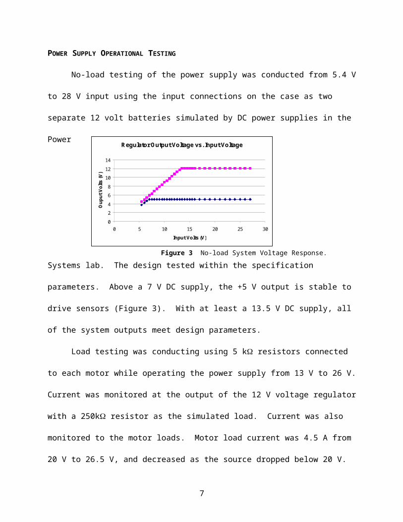
No-load testing of the power supply was conducted from 5.4 V to 28 V input using the
input connections on the case as two separate 12 volt batteries simulated by DC power supplies
in the
Power
Systems
lab. The
design
tested
within the
specification parameters. Above a 7 V DC supply, the +5 V output is stable to drive sensors
(Figure 3). With at least a 13.5 V DC supply, all of the system outputs meet design parameters.
Load testing was conducting using 5 k resistors connected to each motor while
operating the power supply from 13 V to 26 V. Current was monitored at the output of the 12 V
voltage regulator with a 250k resistor as the simulated load. Current was also monitored to the
motor loads. Motor load current was 4.5 A from 20 V to 26.5 V, and decreased as the source
dropped below 20 V. Voltage and current at the output of the 12 V voltage regulator was stable
at source voltages above 13.5 V, and reduced linearly below 13.5 V. These values fit within the
design specifications.
DESIGN LIMITATIONS
Due to cost constraints, several higher power items were left out from the overall design.
The loss of these components will limit the range of motor operation. A DC circuit breaker in
the system prior to the solid-state relay was not included. This would provide greater circuit
Regulator Output Voltage vs. Input Voltage
0
2
4
6
8
10
12
14
0 5 10 15 20 25 30
Input Volts (V)
Oup
ut V
olts
(V)
Figure 3 No-load System Voltage Response.
5
protection. Space has been provided within the power supply box for this future add-on. The
power rating of the Zener diodes and the associated inductors on the motor supply lines are
limited, again due to cost. This will prevent rapid transitions of the motors from forward to
reverse and ensures that any changes in speed must be done slowly to avoid damaging the power
supply.
Proposal for Future Completion
The current design should be modified to provide regulated ± 12VDC and regulated
±5VDC for future sensor enhancements and protection. Attempts to provide this using voltage
regulators has destroyed two 5V regulators and work has been discontinued. Other ideas for
future classes include improved protection schemes on the motor to battery connection, and
designing local non-IC voltage regulators that can handle the swing in the battery voltage.
POWER SUPPLY CONCLUSIONS
Power supplies are a very complicated aspect of electrical engineering. Many engineers
spend their entire careers in this field. The team as a whole did not have a good idea about all
the complexities involved in generating clean power. In essence, constant, unwavering power
was needed by several low power loads (the sensors and microprocessor) and constant high
power was needed by four varying loads (the motors). Aside from just providing power to loads,
the power supply should provide protection for the battery and low-power electronics from
damaging feedback from the motors. There is some worry among the team that the current
protection scheme will protect the circuit from damaging feedback but will regularly burn up in
the process.
6

THE MOTOR DRIVERS
INTRODUCTION
The Motor Driver Team was created to design and build a circuit for independent control
of each of the four motors. An important requirement is both forward and reverse operation.
Research suggested that the best way to accomplish this was to use an H-bridge circuit. An H-
bridge circuit allows both forward and reverse operation as well as a neutral or coast mode.
Control of the H-bridge is done through a forward reverse switch and a pulse-width-modulation
signal from a microcontroller. The H-bridge designed by the motor driver team provides
independent control of each of the four motors with variable speed in both forward and reverse.
MOTOR DRIVER SPECIFICATIONS
Inputs : The set of drivers will receive a forward (0V) or reverse (5V) signal as well as a Pulse
Width Modulated signal from the microprocessor. The logic to control these signals will require
5V. Each driver is supplied its own dedicated, fused 24V line from the power supply. A
common ground will also be supplied from the power supply.
Outputs: Each motor driver will have two outputs. The first is connected to the positive
terminal of its assigned motor and the second is connected to the negative terminal of its
assigned motor.
DESIGN DESCRIPTION
H - Bridge
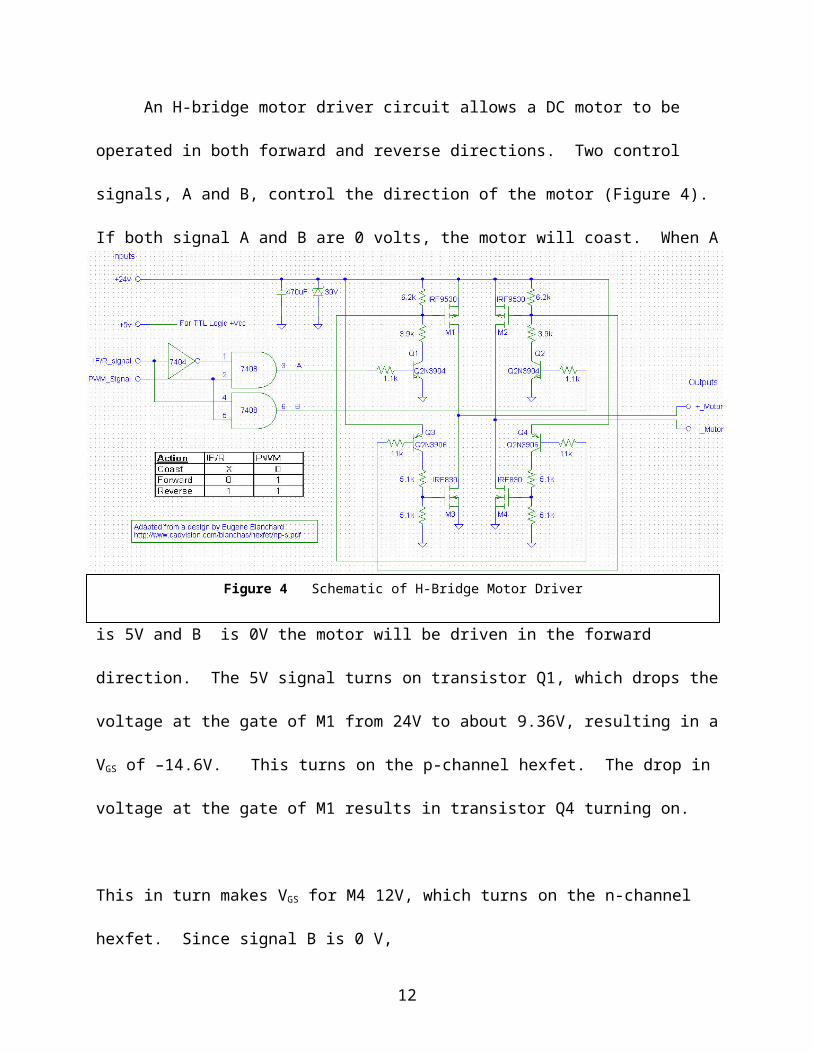
An H-bridge motor driver circuit allows a DC motor to be operated in both forward and
reverse directions. Two control signals, A and B, control the direction of the motor (Figure 4).
7

If both signal A and B are 0 volts, the motor will coast. When A is 5V and B is 0V the motor
will be driven in the forward direction. The 5V signal turns on transistor Q1, which drops the
voltage at the gate of M1 from 24V to about 9.36V, resulting in a VGS of –14.6V. This turns on
the p-channel hexfet. The drop in voltage at the gate of M1 results in transistor Q4 turning on.
This in turn makes VGS for M4 12V, which turns on the n-channel hexfet. Since signal B is 0 V,
both M2 and M3 are turned off. In this state the positive terminal of the motor is at 24V and the
negative terminal of the motor is grounded. The opposite is true when A is 0 V and B is 5 V. In
this state the motor will be driven in the reverse direction. In the case were A is 5 V and B is 5
V, there is a direct short from Vcc to ground. This state should be avoided in normal operation.
In this design, signals A and B are controlled by a simple de-multiplexor. A pulse-width-
modulation (PWM) signal is required from the microprocessor and a forward (0V) or reverse
(5V) control signal is provided from the operator via a toggle switch.
8
Table 1 H-Bridge Parts List
Resistors Hexfets BJTs Capacitors Diodes Additional Parts8x 6.2kΩ 8x IRF9530
P-Channel8x 2N3904NPN
4x 470F 4x Zener 30V 5w
3x 14 pin IC wire wrap socket
8x 3.9kΩ 8x IRF830N-Channel
8x 2N3906PNP
8x MOSFET heatsinks
8x 1.1kΩ 6”x8” perfboard8x 11kΩ 2x 8-position
Barrier Strip16x 5.1kΩ 1x 4-position
Barrier Strip
Logic
Logic is required to determine whether the PWM signal from the microcontroller is for
forward mode or reverse mode. A forward or reverse switch that controls a series of
demultiplexors determines this. If the control signal is 0V (logic 0) the PWM signal is sent to A.
If the control signal is 5V (logic 1) then the PWM signal is sent to B. A potential problem exists
if the PWM signal is high at the same time that the forward reverse switch is flipped. In this case
the 5V signal from the microcontroller could be sent to both A and B. This would result in a
short circuit from 24V to ground. A more complex asynchronous type logic circuit could be
designed to eliminate this problem. For the logic circuit used here, the operator needs to make
sure that the vehicle’s accelerator is at zero before switching direction.
Parts For Logic
Two SN74LS08 Quadruple 2-Input AND Gate chips and one SN74LS04 Hex Inverter
chip were required to construct four demultiplexors. Figure 5 Logic circuit
9

BACK EMF PROTECTION
Electromotive forces, otherwise known as EMF, can be very destructive to a circuit such
as this one. To help counteract the effects of EMF, this design incorporates a 470F capacitor as
well as a Zener diode (Figure 4). The capacitor helps to suppress noise spikes created by the
motor. Positive spikes are created when the motor is acting as a generator. This will typically
happen when the duty cycle provide to the h-bridge is quickly reduced. The voltage generated
by the motor is then added to the voltage supplied by the power supply. The Zener diodes help
to clip the voltage that is being fed back into the battery. Since regenerative braking is not being
implemented in this design, the voltage created by braking or coasting is not desired.
TESTING
The testing was done mainly in the electronics lab, using an oscilloscope, a power supply
and a function generator. The function generator provided the PWM signal to drive the circuit.
Motor outputs were viewed on an oscilloscope. The power supply was used to obtain the
necessary 24V for the motors and 5V for the logic. Initially the output of the circuit was not as
expected. The turn off time of the motor terminals was very slow. This was caused because
there was no load. After placing a 1k resistor between the positive and negative motor
terminal outputs to simulate a load the problem was solved. Figure six shows the input and
output waveforms for three different duty cycles. The test frequency was 1KHz. The
waveforms of the motor output is at 24V for almost exactly the same time that the PWM signal is
at 5V. There is a tiny difference in switching times because the hexfets need some time to turn
on and off. The H-bridge was also tested by connecting a motor to one set of the outputs. The
motor operated exactly as expected. Both forward and reverse modes worked properly. An
10
interesting thing was discovered when
changing the PWM frequency. The motor
resonated at a different audible frequency.
Changing the PWM frequency quickly
almost sounded like an old Nintendo
game.
MOTOR DIVERS CONCLUSION
Overall, the requirements for the
motor driver group were fulfilled.
Independent control of each motor is
possible in both forward and reverse. The
H-bridge design is stable and works in a
variety of conditions. Future
improvements in this design may include
regenerative braking, which would require
changes to this circuit, include adjusting
the Zener diode voltage. This would be
based on the amount of reverse voltage
that the power supply team requires for battery charging.
Figure 6 Output from circuit testing
11

THE SENSORS
INTRODUCTION
The Sensors team was given the task of providing sensors for vehicle control and
monitoring of the motors. The vehicle controls are an accelerator and a brake, implemented
using potentiometers. Two different sensors are used to monitor the motors. First, a current
sensor signals the microprocessor if more than the rated six amps is going through the motor. In
addition, a tachometer is used to monitor the motor rpm’s.
CURRENT SENSORS
Objective
The objective was to design and build the current sensor for each of the four electric
motors. The specs of the current sensors are the following:
-Range of current to be monitored 0 amps to 10 amps
-Output of the sensor 0 V or 5 V
(zero volts for current below eight amps, five volts for current above eight amps)
Two approaches were considered for the current sensor: the Hall Effect sensor or a
simpler method of measuring the voltage across a resistor (Ohm’s Law). The Hall Effect sensor
was rejected because the current levels in the system are too small to get a noticeable Hall Effect.
Series Resistor Information:
The resistor chosen for the current sensor is .15 with a 5 watt rating (TWW5JR15,
OMITE Manufacturing Company). It has a 5% tolerance, which gives it a range of .1425 < R
< .1575. However, the resistor also has a change in resistance with respect to temperature,
which has the equation R=.15(1 + (400/(1*10^6 C))(delta T in C) ). Assuming a temperature
12
range of 0°C to 325°C gives a range, with tolerance in mind also, of .14 < R < .18. In the
actual circuit the series resistance consists of three .15 resistors in parallel to make an effective
resistance of .05. This design will reduce the amount of power dropped across the sensor to
measure current. It will also reduce the operating temperature in the resistors, keeping it more
consistent with air temperature. Each parallel resistor will dissipate a maximum of 1.66Watts at
a current of ten amps, only a third of its rated five watts.
Interpreter Circuit:
The purpose of the interpreter circuit is to measure and interpret the voltage drop across
the resistor, R (Figure 7). The current through the resistor can be calculated by Ohm’s Law. The
interpreter circuit also has to check the current magnitude to see if it is above eight amps.
Figure 7 Interpreter Circuit
13
The first step in the interpreter circuit is the difference circuit using a 741 op-amp. This
circuit subtracts the two voltages measured across R to attain Vr, which is amplified from 0 < Vr
< .5 V to a scale of 0 < A(Vr ) < 8.3 V (where A=16.6666). The next is to compare the voltage
A(Vr) to a preset voltage of 6.7 volts to see if the measured voltage is above eight volts. If the
measured voltage is above eight volts, the output of the comparator circuit will go to negative
saturation, turning off the N-Mosfet to give a five volts signal to the microprocessor. The preset
6.7 volts and the 5V are created using a Zener diode in series with a resistor and op-amps,
amplifying the 5.1V reference voltage across the Zener diode to make the preset 6.7 V and the
5V lines for the rest of the interpreter circuit to use.
Table 2 Outputs to micro-processor
Current (Vr) A(Vr) Output to micro-pros.less than 8 amps less than .4 V Less than 6.7 V -VssGreater than 8 amps more than 6.4 V more than 6.7 V (-Vss to + 5)
Table 3 Parts usedType Company Part #LM258 ST LM158P MOSSFET International Rectifiers IRFD9123N MOSSFET International Rectifiers IRFD014
THROTTLE AND BRAKING SENSORS
Objective
The objective of the throttle and braking sensors is to design a variable output that will be
interpreted by the micro-controller in order to vary the speed and braking of the vehicle.
Circuit Description
14

The circuit uses a potentiometer in parallel with a +5V DC source in order to provide a
variable voltage to the micro-controller
(Figure 8). The micro-controller should
then change the motor speed according
to the voltage level received from the
sensor, a range of 0 – 4.7 volts DC. The
capacitor is added to the circuit to filter out noise and to stabilize the voltage level out of the
potentiometer. The 4.7V Zener diodes are introduced into the circuit in order to protect the
micro-controller from any voltage spikes.
Table 4 Throttle Parts
Quantity Part2 0.1uF Capacitor2 10K Potentiometer4 4.7V, 5W, Zener Diode
TACHOMETER SENSORS
Objective
The object of the tachometer sensors is to provide the micro-controller with a real time
measurement of the shaft speed. This measurement can be used by the micro-controller to
implement traction control on the vehicle. Pre-built tachometers are available and optical
encoders were researched for this function, but a more economical approach that still provides an
accurate signal was chosen.
Requirements
Output: Four digital signals, each pulsing between 0 and 5 volts.
Figure 8 Throttle Sensor
15
Input: +5V from power supply.
Circuit Description
Four identical circuits were constructed—one for each drive motor. Stepper motors are
connected to the drive motor’s shaft via a small belt. Output from the stepper motors is a
sinusoidal wave with amplitude in
excess of 30 volts at high RPM. A
4.7V Zener diode is connected across
the stepper motor to limit output to -
0.6V and +4.7V. This signal is
connected to a comparator (LM337).
The output of the comparator pulses
from 0 to 5 volts, producing a square-
wave output. A large feedback resistor was added to provide noise-reducing hysteresis.
Table 4 Parts used
Quantity Item4 Stepper motor4 4.7V Zener Diode12 1 M ohm Resistor4 Quad comparator LM339
SENSORS CONCLUSION
The goal of the sensors team was to provide the microprocessor with the current state of
the controls and movement of the motors. A throttle and brake were constructed to provide user
Figure 9 Tachometer Circuit
16

input, while current sensors and tachometers were used to return the state of the drive motors to
the microprocessor. As with most design projects, problems were encountered during the
design. The current sensors design was changed towards the end of the project to accommodate
higher current. The tachometer circuit had a lot of noise until feedback was implemented. In
testing, the final design met the required specifications.
THE MICROPROCESSOR
INTRODUCTION
The microprocessor is the means by which all the individual components become an
integrated system. It must interact seamlessly with each of the sub-systems to achieve the
desired results. To do this, the Microprocessor team chose the Motorola 68hc12 microprocessor.
Each of the sub-systems must interact with the processor in the following way:
Power Supply The microprocessor needs a constant 5 – 6 volt power supply for it to operate
effectively. The power supply team is providing a regulated 12 volt supply that will be further
regulated by the hc12.
Sensors The sensor signals are critical to the control of the vehicle. The processor collects
sensor data through the A/D converter or one of several digital ports. The data is then used to
determine the PWM signal to the motor drivers.
Motor Drivers The microprocessor creates four independent PWM signals to drive each of the
motors.
17

SOFTWARE DESIGN
The micro controller will receive twelve volts from the power supply to energize the unit.
It will also receive nine separate input signals, which will be read, stored, and processed to
determine the pulse-width modulated output signals that will control the movement of the
vehicle. These signals are generated from the micro-controller from the Pulse Width Modulator.
It then makes adjustments to the system through the motor control circuit to ensure it is operating
in a way that is requested by the user and within the circuit specifications. This includes such
safety measures as shutting down a motor when an over-current situation is signaled, protecting
the system from damage due to unexpected events.
FUTURE ADDITIONS
Due to time and cost constraints, it was not possible to address all of the concerns of the
control of the vehicle. Downhill grades where the weight of the vehicle causes an over-speed
condition were not addressed at this time. Another issue that was not discussed was the handling
of the vehicle during an uphill stall, when over current conditions would most likely be
encountered. These considerations, along with added design features, like power-assisted
steering and regenerative braking, would be excellent additions to the vehicle’s capability.
MICROPROCESSOR CONCLUSION
While the microprocessor does provide four-wheel independent-drive to the motors, it is
also the area that needs the most work to implement all of the desired design features. Perhaps the
most challenging will be power-assisted steering. In the end, it is the microprocessor that brings
the entire system together.
18

CONCLUSION
The project goals laid out at the outset specified a vehicle with independent four-wheel
drive and basic acceleration and braking controls. Individually, the four teams each accomplished
their goals. However, as with any design project, bringing it all together is an added challenge.
One trouble spot was the motors chosen for the vehicle. While operating within their optimum
power range, the motors have plenty of torque to move the cart. The starting torque though, is not
enough to move the cart. Because of this, there were several last minute changes that sent teams
scrambling to modify their designs.
Other problems include the cart on which the system was installed. It will have trouble
holding together for a trip down the hall, let alone on any terrain. To be truly effective, this design
should be tackled by a multiple discipline team consisting of Industrial or Mechanical engineers to
design the vehicle, and electrical engineers to design the vehicle controls. The result could truly be
an “all-terrain” vehicle.
19
REFERENCES
Blanchard, Eugene. "A Better H Bridge." April 2001. http://www.cadvision.com/blanchas/hexfet
(1 Apr. 2002).
Lines, D. (1991). Building Power Supplies: Useful Designs for Hobbyists and Technicians.
Master Publishing, Inc.
M68HC12B Family (2000). HC12: M68HC12B Family Advance Information. Technical
Manual provided with HC-12 Microprocessor via MOTOROLA, Inc.
Motorola MC7800 Series (1996). Revision 4. Three-Terminal Positive Voltage Regulators.
Retrieved March 21, 2002 from the World Wide Web:
http://www.crownhill.co.uk/m7812.pdf
Ramaswamy, V. (1999). Interactive Power Electronics On-line Text.
Retrieved March 21, 2002 from the World Wide Web:
http://www.ee.uts.edu.au/~venkat/pe_html/contents.htm
20


![Voltage Dividers and Current Dividers · Microsoft PowerPoint - Chapter07.ppt [Read-Only] Author: AJGero Created Date: 2/24/2012 7:53:52 PM ...](https://static.fdocuments.in/doc/165x107/5ecfea2e0eadce7cdd405364/voltage-dividers-and-current-dividers-microsoft-powerpoint-chapter07ppt-read-only.jpg)