
SNAP-LCE USER’S GUIDE - Opto 22 to digital and analog sensors and actuators as well as serial...
56
SNAP-LCE USER’S GUIDE Form 1475-120726—July 2012 43044 Business Park Drive • Temecula • CA 92590-3614 Phone: 800-321-OPTO (6786) or 951-695-3000 Fax: 800-832-OPTO (6786) or 951-695-2712 www.opto22.com Product Support Services 800-TEK-OPTO (835-6786) or 951-695-3080 Fax: 951-695-3017 Email: [email protected] Web: support.opto22.com
Transcript of SNAP-LCE USER’S GUIDE - Opto 22 to digital and analog sensors and actuators as well as serial...

SNAP-LCE USER’S GUIDE
Form 1475-120726—July 2012
43044 Business Park Drive • Temecula • CA 92590-3614Phone: 800-321-OPTO (6786) or 951-695-3000
Fax: 800-832-OPTO (6786) or 951-695-2712www.opto22.com
Product Support Services800-TEK-OPTO (835-6786) or 951-695-3080
Fax: 951-695-3017Email: [email protected]
Web: support.opto22.com

SNAP-LCE User’s GuideForm 1475-120726—July 2012
Copyright © 1997–2012 Opto 22.All rights reserved.Printed in the United States of America.
The information in this manual has been checked carefully and is believed to be accurate; however, Opto 22 assumes no responsibility for possible inaccuracies or omissions. Specifications are subject to change without notice.
Opto 22 warrants all of its products to be free from defects in material or workmanship for 30 months from the manufacturing date code. This warranty is limited to the original cost of the unit only and does not cover installation, labor, or any other contingent costs. Opto 22 I/O modules and solid-state relays with date codes of 1/96 or later are guaranteed for life. This lifetime warranty excludes reed relay, SNAP serial communication modules, SNAP PID modules, and modules that contain mechanical contacts or switches. Opto 22 does not warrant any product, components, or parts not manufactured by Opto 22; for these items, the warranty from the original manufacturer applies. These products include, but are not limited to, OptoTerminal-G70, OptoTerminal-G75, and Sony Ericsson GT-48; see the product data sheet for specific warranty information. Refer to Opto 22 form number 1042 for complete warranty information.
Wired+Wireless controllers and brains and N-TRON wireless access points are licensed under one or more of the following patents: U.S. Patent No(s). 5282222, RE37802, 6963617; Canadian Patent No. 2064975; European Patent No. 1142245; French Patent No. 1142245; British Patent No. 1142245; Japanese Patent No. 2002535925A; German Patent No. 60011224.
Opto 22 FactoryFloor, Optomux, and Pamux are registered trademarks of Opto 22. Generation 4, ioControl, ioDisplay, ioManager, ioProject, ioUtilities, mistic, Nvio, Nvio.net Web Portal, OptoConnect, OptoControl, OptoDataLink, OptoDisplay, OptoEMU, OptoEMU Sensor, OptoEMU Server, OptoOPCServer, OptoScript, OptoServer, OptoTerminal, OptoUtilities, PAC Control, PAC Display, PAC Manager, PAC Project, SNAP Ethernet I/O, SNAP I/O, SNAP OEM I/O, SNAP PAC System, SNAP Simple I/O, SNAP Ultimate I/O, and Wired+Wireless are trademarks of Opto 22.
ActiveX, JScript, Microsoft, MS-DOS, VBScript, Visual Basic, Visual C++, Windows, and Windows Vista are either registered trademarks or trademarks of Microsoft Corporation in the United States and other countries. Linux is a registered trademark of Linus Torvalds. Unicenter is a registered trademark of Computer Associates International, Inc. ARCNET is a registered trademark of Datapoint Corporation. Modbus is a registered trademark of Schneider Electric. Wiegand is a registered trademark of Sensor Engineering Corporation. Nokia, Nokia M2M Platform, Nokia M2M Gateway Software, and Nokia 31 GSM Connectivity Terminal are trademarks or registered trademarks of Nokia Corporation. Sony is a trademark of Sony Corporation. Ericsson is a trademark of Telefonaktiebolaget LM Ericsson. CompactLogix, MicroLogix, SLC, and RSLogix are trademarks of Rockwell Automation. Allen-Bradley and ControlLogix are a registered trademarks of Rockwell Automation. CIP and EtherNet/IP are trademarks of ODVA.
All other brand or product names are trademarks or registered trademarks of their respective companies or organizations.
SNAP-LCE User’s Guideii

Table of Contents
Chapter 1: Installation and Specifications................................................. 1
Introduction ............................................................................................................................1Software..........................................................................................................................2About this Guide..............................................................................................................3Related Documentation...................................................................................................3For Help ...........................................................................................................................4
Quick Start ..............................................................................................................................5What You Will Need .......................................................................................................5Installing Software..........................................................................................................5Installing Hardware.........................................................................................................5What’s Next?...................................................................................................................6Mounting the Controller ..................................................................................................7
Panel Mounting and Dimensions .............................................................................7DIN-Rail Mounting and Dimensions ........................................................................8
Architectural Diagrams ..........................................................................................................9
Specifications .......................................................................................................................10Power Supply Recommendations..................................................................................10LED Descriptions ...........................................................................................................11
Chapter 2: Optional Features..................................................................... 13
Introduction ..........................................................................................................................13Communication Options ................................................................................................13
Configuring Serial Ports .......................................................................................................13
Configuring PPP ....................................................................................................................16Configuring PPP on the Controller .................................................................................17Attaching the Modem to the Controller........................................................................20Configuring Microsoft Windows Dial-up Networking on Windows 2000....................21Setting Up a Remote Access Server on the PC (Windows 2000 Advanced Server).....25
Configuring Security .............................................................................................................28Limiting Access to Specific Computers.........................................................................28
SNAP-LCE User’s Guide iii

Limiting Access to Specific Protocols ...........................................................................28Requiring a Password for FTP .......................................................................................29Protecting a PAC Control Strategy from Interference...................................................29
Changing Date and Time ......................................................................................................29
Chapter 3: Maintenance and Troubleshooting........................................ 31
Maintenance ........................................................................................................................31Assigning an IP Address................................................................................................31Changing the IP Address ...............................................................................................31Writing Commands to the Controller ............................................................................34Resetting the Controller to Factory Defaults ................................................................35Loading New Firmware .................................................................................................36Replacing the Backup Battery .......................................................................................36
Troubleshooting....................................................................................................................37Communicating with the SNAP-LCE Controller ............................................................37
Pinging the SNAP-LCE............................................................................................37Accessing the SNAP-LCE with ioManager ...................................................................38Communicating with I/O Units ......................................................................................40Solving Network Problems............................................................................................40
Create a Network Diagram ....................................................................................40Check Ethernet Errors.............................................................................................40Analyze Communication Packets ...........................................................................41Have Your Network Certified .................................................................................41
TCP Settings ..................................................................................................................41Getting Device and Firmware Information....................................................................43Blink Codes for the SNAP-LCE ......................................................................................45
About the SNAP-LCE’s Memory Map ..................................................................................46Using Data for Peer-to-Peer Communication................................................................46
Using ioControl for Scratch Pad Access.................................................................46Writing Your Own Applications for Scratch Pad Access .......................................47
Index ............................................................................................................. 49
iv SNAP-LCE User’s Guide

CHAPTER 1
Chapter 1
Installation and Specifications
IntroductionIMPORTANT: The SNAP-LCE controller covered in this guide is no longer recommended for new development. Because it has reached its hardware limits, we have had to replace it with new SNAP PAC controllers. SNAP PAC controllers are more powerful and include additional functionality. Please see our website, www.opto22.com, or call us at 800-321-6786 or 951-695-3000 for information about SNAP PAC controllers.
The SNAP-LCE Ethernet-based, stand-alone industrial controller is designed for use with Opto 22’s ioControl™ Basic software, part of the ioProject™ Basic software suite. Please note that SNAP-LCEs and ioProject are not recommended for new development. The last released version of ioProject Basic is version 7.1. This software will remain available on our website for some time to support customers who have existing SNAP-LCE controllers. For new development, we recommend SNAP-PAC controllers (either standalone or on-the-rack) and PAC Project software. See form #1688, the SNAP PAC System Migration Technical Note, for guidelines on mixing older and newer hardware and software.
The SNAP-LCE provides real-time control and communication to SNAP Ethernet-based input/output (I/O) systems and computer networks. Independently running a control program you build with the included ioControl development software, the SNAP-LCE monitors and controls all kinds of devices and equipment. It also communicates data about these devices and equipment directly to Opto 22’s ioDisplay™ and third-party human-machine interfaces (HMIs), to databases, and to other information technology (IT) systems.
The controller communicates over standard TCP/IP Ethernet networks at 10 or 100 Mbps. It can be attached to existing wired or wireless Ethernet networks or be used in an independent control network built with standard, off-the-shelf Ethernet hardware. Communication with a SNAP-LCE controller can also be established via a modem connection using Point-to-Point Protocol (PPP),
SNAP-LCE User’s Guide 1

CHAPTER 1: INSTALLATION AND SPECIFICATIONS
with firmware version 5.1c and newer. Wireless or wireline modem connections are ideal for remote locations where an Ethernet network is not practical.
The SNAP-LCE controller includes a 10/100 Mbps Fast Ethernet port for networking through an Ethernet switch to SNAP Simple, SNAP Ethernet, and SNAP Ultimate I/O units, which provide the connections to digital and analog sensors and actuators as well as serial devices. (Please note that SNAP Simple, Ethernet, and Ultimate I/O units have been replaced by SNAP PAC I/O units.)
The controller also includes two serial ports for use with a modem connection using PPP or for general-purpose communication with serial devices (requires firmware version 5.1c or newer). Using this option, you can send and receive data from one or two serial devices connected directly to the controller, rather than requiring a SNAP serial communication module on an attached I/O unit. Your ioControl strategy controls communication with the devices and uses the data as needed in control logic. Note that these two ports are not isolated from each other.
The SNAP-LCE simultaneously runs up to 16 ioControl flowcharts, plus the host task. The control strategy can contain a much larger number of flowcharts, however; the total number is limited only by the 8 MB of controller memory available for strategy storage.
Since the SNAP-LCE and the I/O units it controls have IP addresses like other devices on an Ethernet network, the number of points the controller can address is theoretically unlimited. The SNAP-LCE can control many SNAP Ethernet-based I/O units. Because the controller scans I/O only when your strategy logic requests it, the exact number of I/O points it can scan—and the scanning performance—depend on the architecture of your strategy.
SoftwareThe SNAP-LCE controller is compatible with Opto 22’s ioProject Basic software suite, which consists of three components:
• ioControl Basic—a graphical, flowchart-based programming tool for machine control and process applications. Using ioControl, you create, download, and run control programs on the SNAP-LCE controller. In addition to flowchart programming (with subroutine capability), ioControl includes a powerful, built-in scripting language based on C and other procedural languages.
• ioDisplay Basic—an intuitive HMI package for building operator interfaces for your Microsoft® Windows®-based clients communicating with a SNAP-LCE controller. ioDisplay offers a full-featured HMI including alarming, trending, and a built-in library of 3,000 industrial automation graphics.
• ioManager™—a utility application used to assign an IP address to the SNAP-LCE, read or change basic controller configuration, and more. In addition, you can use ioManager to configure the I/O units that communicate with the controller and to read from or write to I/O units.
ioProject Basic is included on the CD that comes with the SNAP-LCE controller and is also available for download from our website at www.opto22.com. For communication using OLE for Process Control (OPC), you can purchase OptoOPCServer™, Opto 22’s OPC 2.0-compliant server, separately.
2 SNAP-LCE User’s Guide

CHAPTER 1: INSTALLATION AND SPECIFICATIONS
About this GuideThis guide includes:
Chapter 1, “Installation and Specifications,” gives you quick installation instructions to get your SNAP-LCE industrial controller running. It also includes product support information, architectural diagrams, and specifications for the controller.
Chapter 2, “Optional Features,” shows you how to use the SNAP-LCE controller to communicate directly with serial devices, and how to set up PPP if you are using the controller with a modem.
Chapter 3, “Maintenance and Troubleshooting,” includes steps for working with IP addresses, loading new firmware, troubleshooting problems with the SNAP-LCE, and information about the controller’s memory map.
Related DocumentationYou may also need the following documentation, depending on your application:
All of this documentation is on the CD that came with the controller; all forms are also available on our website (www.opto22.com) for downloading. The easiest way to find one is to search on the form number.
To use this See this Opto 22 form #
SNAP-LCE controller and Opto 22 I/O units
ioManager User’s Guide 1440
SNAP Ultimate I/OSNAP Ethernet I/OSNAP Simple I/O
SNAP Ethernet-Based I/O Units User’s Guide 1460
ioControl strategies ioControl User’s GuideioControl Command ReferenceioControl Commands Quick Reference Card
130013011314
Custom applications you develop
OptoMMP Protocol Guide 1465
SNAP-LCE User’s Guide 3
CHAPTER 1: INSTALLATION AND SPECIFICATIONS
For HelpIf you have problems installing or using a SNAP-LCE controller and cannot find the help you need in this guide, contact Opto 22 Product Support.
Phone: 800-TEK-OPTO (835-6786)951-695-3080(Hours are Monday through Friday, 7 a.m. to 5 p.m. Pacific Time)
Fax: 951-695-3017
Email: [email protected]
Opto 22 website: www.opto22.com
When calling for technical support, be prepared to provide the following information about your system to the Product Support engineer:
• Software and version being used
• Controller firmware version (see“Getting Device and Firmware Information” on page 43)
• PC configuration
• A complete description of your hardware and operating systems, including:
– jumper configuration
– type of power supply
– types of I/O units installed
– third-party devices installed (for example, barcode readers)
• Specific error messages seen.
NOTE: Email messages and phone calls to Opto 22 Product Support are grouped together and answered in the order received.
4 SNAP-LCE User’s Guide

CHAPTER 1: INSTALLATION AND SPECIFICATIONS
Quick Start
What You Will Need• PC running Microsoft Windows 2000 or XP workstation operating system, with a 10/100
MB Ethernet adapter card, the TCP/IP protocol installed, and a valid IP address, on the same subnet as the controller.
• Crossover cable (for direct connection to the PC) or an available connection to a standard 10BASE-T or 100BASE-TX Ethernet network.
• SNAP-LCE industrial controller
• CD that came with the SNAP-LCE
• A SNAP-PS5 or SNAP-PS5U power supply or other 5 VDC power supply (-0/+0.1 VDC at 4.0 or 5.0 A)
• Small flathead screwdriver
• Opto 22 SNAP Ethernet-based I/O units—SNAP Simple I/O, SNAP Ethernet I/O, or SNAP Ultimate I/O units—on the same Ethernet network as the controller.
Installing SoftwareIn your CD-ROM drive, insert the CD that came with the SNAP-LCE. The installation wizard should start automatically. If it doesn’t, use Windows Explorer to navigate to your CD-ROM drive and then double-click setup-exe.
Installing Hardware1. Install Opto 22 I/O units according to instructions in form #1460, the SNAP Ethernet-Based
I/O Units User’s Guide.
This guide is on the CD that was shipped with the controller or the I/O unit’s brain; it is also available from our website at www.opto22.com.
2. Choose a convenient mounting location for the SNAP-LCE and either DIN-rail or panel mount it according to the diagrams on page 7 and page 8.
3. With the power supply off or unplugged, connect the power supply to the SNAP-LCE.
CAUTION: Reversing wire polarity may cause damage to your controller. This damage is not covered by Opto 22’s warranty. If in doubt about which wire is which on your power supply, check with a meter.
a. With the power supply off or unplugged, connect the +5 V lead from the power supply (normally red) to the +5 V terminal on the face of the SNAP-LCE.
b. Connect the COM wire from the power supply (normally black) to the –5 V terminal on the face of the SNAP-LCE.
SNAP-LCE User’s Guide 5

CHAPTER 1: INSTALLATION AND SPECIFICATIONS
6 SNAP-LCE User’s Guide
NOTE: The controller does not have a power switch; to turn it off, switch off the power supply.
4. Using Category 5 or superior solid unshielded twisted-pair cable, connect the SNAP-LCE controller in one of the following ways:
• (Recommended for initial configuration) Connect to a PC directly, using an Ethernet crossover cable.
• Connect to a standard 10BASE-T or 100BASE-TX Ethernet network that has a PC on the same subnet as the controller and does NOT have a Dynamic Host Configuration Protocol (DHCP) server.Maximum cable or segment lengh is 100 meters; minimum cable length is one meter.
5. Before turning on power to the SNAP-LCE controller, follow steps in Opto 22 form #1440, the ioManager User’s Guide, to assign the controller an IP address.
This guide is in Adobe Acrobat PDF format on the CD that came with the controller and is also available from our website, www.opto22.com. Note that you can use ioManager to assign IP addresses to the controller and I/O units at the same time.
What’s Next?Your SNAP-LCE industrial controller is now ready for use.
• To create ioControl strategies to run on the controller, see the ioControl User’s Guide and the ioControl Command Reference. Both are available in PDF format on the CD that came with the controller.
• To configure these optional features, see the pages shown. (Instructions are also in the “Reading and Writing” chapter of the ioManager User’s Guide.)
• To work with the controller’s file system and FTP, see instructions in the ioManager User’s Guide.
To configure this: See: Notes
PPP (dial-up over a modem) page 16 Requires firmware 5.1c or newer
Serial ports page 13 Requires firmware 5.1c or newer
IP Security page 28
Date and Time page 29

CHAPTER 1: INSTALLATION AND SPECIFICATIONS
Mounting the ControllerThe SNAP-LCE controller can be panel mounted or mounted on a DIN rail. DIN-rail mounting requires an adapter clip, part number SNAP-PSDIN (not included). The controller is the same size and shape as most SNAP power supplies.
Panel Mounting and Dimensions
Use two screws on each side of the SNAP-LCE controller to mount it to a panel.
SNAP-LCE User’s Guide 7

CHAPTER 1: INSTALLATION AND SPECIFICATIONS
DIN-Rail Mounting and Dimensions
DIN-rail mounting requires an adapter clip, part number SNAP-PSDIN (not included).
For DIN-rail mounting, remove the four screws that fasten the panel mounting base plate to the controller. Save screws. Remove the base plate.
Use the four screws to fasten the DIN-rail adapter clip to the bottom of the controller, as shown.
Optional DIN-rail adapter clip
8 SNAP-LCE User’s Guide

CHAPTER 1: INSTALLATION AND SPECIFICATIONS
Architectural DiagramsTo use the SNAP-LCE with mutliple SNAP Ethernet-based I/O units, use a standard Ethernet hub or switch. This architecture can be designed for control only, as shown below, or be part of a larger Ethernet network that includes computers and other Ethernet-based equipment.
For remote monitoring and control, you can use the SNAP-LCE directly with a SNAP Ethernet-based I/O unit such as the SNAP Simple I/O unit shown in the diagram below. For this use, the SNAP-LCE communicates using a modem over the Point-to-Point Protocol (PPP, supported in firmware version 5.1c and newer). See “Configuring PPP” on page 16.
SNAP-LCE User’s Guide 9

CHAPTER 1: INSTALLATION AND SPECIFICATIONS
Specifications Specification Table:
Power Supply RecommendationsOpto 22 recommends that the SNAP-LCE be powered with an Opto 22 SNAP-PS5 or SNAP-PS5U power supply. In lieu of the SNAP-PS5 or SNAP-PS5U, Opto 22 recommends a 5-volt linear supply with adequate current ratings for the load.
Processor 32-bit ColdFire® 5407
MemoryTotal RAMBattery-backed RAMFlash EEPROM
16 MB512 KB 8 MB (7 MB with firmware version 7.2)
Backup battery 3-volt CR2032 Lithium, user replaceable. Typical service life with power off: 5 years.
Host communication Ethernet (10/100 Mbps) or PPP (dial-up and radio modem)
I/O communication Ethernet (10/100 Mbps)
I/O unit compatibility Opto 22 SNAP Simple I/O, SNAP Ethernet I/O, and SNAP Ultimate I/O units
Serial ports Two RS-232 ports. Baud rate is soft-selectable from 150–115,200 kBd.
Power requirements 5.0–5.2 VDC at 1.2 A
Operating temperature 0 oC to 60 oC
Storage temperature -40 oC to 85 oC
Humidity 0% to 95% relative humidity, non-condensing
Software ioProject software suite (ioControl, ioDisplay, ioManager)Purchase OptoOPCServer separately to communicate using OPC.
Other features FTP server/client with file systemReal-time clock
10 SNAP-LCE User’s Guide

CHAPTER 1: INSTALLATION AND SPECIFICATIONS
LED DescriptionsThe SNAP-LCE includes the following LEDs:
ACT—Network activity is present.
LNK—Controller is connected to the Ethernet network.
TX—(one for each serial port) Controller is actively transmitting data through the port.
RX—(one for each serial port) Controller is actively receiving data through the port.
RUN—Controller is operational.
STS—If on solidly, a strategy is running and a user task is being executed. If the strategy runs to completion, the LED turns off. If the LED is blinking, see “Blink Codes for the SNAP-LCE” on page 45.
SNAP-LCE User’s Guide 11

CHAPTER 1: INSTALLATION AND SPECIFICATIONS
12 SNAP-LCE User’s Guide

CHAPTER 2
Chapter 2
Optional Features
IntroductionThis chapter shows you how to configure optional features for the SNAP-LCE industrial controller. Optional features include communication options (see below), security (page 28), and changing the date and time (page 29).
Communication OptionsIn most cases you will communicate with the SNAP-LCE controller using a wired Ethernet network. However, two communication options are also provided:
• In addition to using the SNAP-LCE on an Ethernet network, you can communicate directly with one or two serial devices through the serial connectors on top of the SNAP-LCE controller (see next section).
• Instead of using a wired Ethernet network, you can communicate with the SNAP-LCE via modem, using the point-to-point protocol (PPP; see page 16).
NOTE: Communication options are configured using ioManager.’s Inspect window. As you use it, remember that ioManager is a comprehensive utility used for several Opto 22 Ethernet-based products. Some items will appear in the ioManager Inspect window that apply to an I/O unit but not to the SNAP-LCE.
Configuring Serial Ports (Requires firmware version 5.1c or newer.) Two RS-232 serial connectors are located on the top of SNAP-LCE controllers. These ports are used for maintenance, such as loading new firmware, or for Point-to-Point Protocol (PPP) communication via modem. However, they can also be used to send or receive data directly from a serial device, such as barcode readers, weigh scales, or any intelligent device with a serial port. Communication is done through ioControl communication handles. (For more information, see “Communication Commands” in Chapter 10 of the ioControl User’s Guide.) Note that these two ports are not isolated from each other.
SNAP-LCE User’s Guide 13

CHAPTER 2: OPTIONAL FEATURES
NOTE: This section shows you how to configure the controller to talk serially with devices directly connected to it. Serial devices attached to an I/O unit through serial communication modules on the rack are configured through ioControl.
1. Make sure a SNAP-LCEthe controller has firmware version 5.1c or newer.
New firmware can be downloaded from our website, www.opto22.com.
2. In the ioManager main window, click the Inspect button .
The Inspect window opens:
If you have used the Inspect window before, the last IP address you used is shown and current Status Read information appears in the window. The most recently used IP addresses are available in the drop-down list. If you have not used the Inspect window before, the window will not show any data.
14 SNAP-LCE User’s Guide

CHAPTER 2: OPTIONAL FEATURES
3. In the IP Address field, type the IP address of the controller (or choose it from the drop-down list). Click Communications and choose Communication Port Control from the submenu.
– Port 0 = Port A on the SNAP-LCE
– Port 1 = Port B on the SNAP-LCE
SNAP-LCE User’s Guide 15

CHAPTER 2: OPTIONAL FEATURES
For each port that is directly connected to a serial device, do the following:
a. In the Control Function for Communication Port value field, choose None from the drop-down list.
b. In the Logging for Communication Port field, leave the value field set to Disabled.This log file is used for PPP or M2M troubleshooting. When the control function is set to None, the log file logs only characters received by the ioControl strategy. Since ioControl is handling the data, you don’t need the log file.
4. When you have finished configuring the ports, click Apply.
Configuration data is sent to the controller.
5. Click the Status Write button on the left side of the Inspect window. In the Operation Command list, highlight Store configuration to flash.
6. Click Send Command.
The port configuration data is stored to flash memory and a Success message appears.
Configuring PPPUse this section only if you have SNAP-LCE controllers installed at remote locations or in other places where an Ethernet network is not available, and you are using modems to communicate between the controller and a PC. You can set up communication so that the controller can dial in to a PC, so that PCs can dial into the controller, or both.
16 SNAP-LCE User’s Guide

CHAPTER 2: OPTIONAL FEATURES
First, configure PPP on the controller itself following steps in the next section. Then, see the following sections to attach the modem to the system and set up Windows dial-up networking or remote access server on the PC.
Configuring PPP on the Controller1. In the ioManager main window, click the Inspect button .
The Inspect window opens:
If you have used the Inspect window before, the last IP address you used is shown and current Status Read information appears in the window. The most recently used IP addresses are available in the drop-down list. If you have not used the Inspect window before, the window will not show any data.
SNAP-LCE User’s Guide 17

CHAPTER 2: OPTIONAL FEATURES
2. In the IP Address field, type the IP address of the SNAP-LCE controller (or choose it from the drop-down list). Click Communications and choose PPP Configure from the submenu.
3. Enter the Local IP Address for the PPP interface on the controller. Enter the local Subnet Mask only if you are using classless IP addressing. If you are not using classless IP addressing, leave the Subnet Mask at zero, and the controller will calculate the subnet mask.
IMPORTANT: The network address for the PPP interface must be different from the network ID for the Ethernet interface. (The network address is obtained by ANDing the IP address and the subnet mask.)
4. Change Serial Port parameters as necessary (speed, parity, etc.).
5. Change the Modem Initialization String and Modem Hangup String if necessary. Make sure you use the setting to ignore DTR signal in the modem initialization string:
The default modem initialization string is AT&D0^M~~~~
Consult the command reference that came with your modem to determine the correct initialization command strings. A sample modem initialization string might look like this:
AT&F^M~~AT&D0&K0^M~~AT&W0^M~~AT&Y0M~~
The &F command sets the modem back to factory defaults. The ^M tells the controller to insert a carriage return. The ~ tells it to insert a 500ms pause. The &W0 writes the current settings to NVRAM profile 0 on the modem. The &Y0 instructs the modem to use NVRAM profile 0 after resetting. This initialization string is just a sample; command strings for your modem may differ.
18 SNAP-LCE User’s Guide

CHAPTER 2: OPTIONAL FEATURES
6. In the Max Authentication Retries field, enter the maximum number of times a login/password combination can be retried.
7. If the controller will receive incoming calls via modem, complete the Incoming PPP section:
a. Enable PPP for Incoming: Choose Enabled from the drop-down list.b. Set Default Gateway: If you want the controller to use the device calling the controller
as the default gateway for all communication, choose Yes. The default is No. c. Remote IP Address: Enter the IP address the controller should give to devices that dial
into the controller and ask for an address. This address must be on the same subnet as the local IP address.
d. Enter a Modem Listen String to make sure the modem automatically answers calls. The default modem listen string is ATS0=1^M~ , which instructs the modem to answer any incoming calls on the first ring. Again, refer to your modem’s command reference for the correct listen string.
e. Change the Inactivity Timeout if necessary. The default is 30.f. Enter the Login and Password the controller should accept for incoming calls.
8. If the controller will send outgoing calls, complete the Outgoing PPP section:
a. Enable PPP for Outgoing: Choose Enabled from the drop-down list.b. Specify Local IP Address: Choose Yes to have the controller use the Local IP Address
you entered for the PPP link; choose No to have the remote device assign the controller an IP address for the PPP link. The default is No.
c. Set Default Gateway: If you want the controller to use the device the controller is calling as the default gateway for all communication, choose Yes.
d. PPP Link Always Connected: If you don’t want the controller to dial out, choose Yes.e. Enter the Login and Password the controller should use for authentication when it calls
the remote device.f. Inactivity Timeout: Enter number of seconds after the PPP session is negotiated before
the modem hangs up if the controller sends no packets and receives no packets. The default is 30.
g. Phone Number: Enter the number the modem should dial for outgoing calls from the controller.
h. Change the following fields if necessary:– Max Connect Time—The maximum amount of time in seconds an outgoing PPP
connection can stay connected after successful negotiation. Default is zero, which disables the timer.
– Max Dial Retries—The number of times the controller will redial if the first attempt fails. Default is zero.
– Retry Interval—The number of seconds the controller will wait before trying to redial after the first attempt fails. Default is zero.
– Disable Time—If the maximum connect time or maximum number of retries has been reached, the outgoing PPP dialer waits this number of seconds before doing anything. Default is zero.
SNAP-LCE User’s Guide 19

CHAPTER 2: OPTIONAL FEATURES
9. When you have finished configuring PPP, click Apply.
Configuration data is sent to the controller. For it to take effect, you must save the data to flash and restart the controller (see next steps).
10. Click the Status Write button on the left side of the Inspect window. In the Operation Command list, highlight Store configuration to flash.
11. Click Send Command.
The PPP configuration data is stored to flash memory and a Success message appears.
12. In the Operation Command list, highlight Restart I/O Unit from powerup. Click Send Command.
The controller is restarted and a Success message appears.
13. Continue with the next section to attach the modem to the controller.
Attaching the Modem to the ControllerTo work properly with the SNAP-LCE controller, a modem must be able to store settings in non-volatile RAM (NVRAM) and default to those settings on reset.
20 SNAP-LCE User’s Guide

CHAPTER 2: OPTIONAL FEATURES
1. Follow the diagram at right to attach the modem to the controller using the controller’s serial connector.
2. Store configuration settings to the modem’s NVRAM, following instructions in the user’s guide for your modem.
NOTE: Configuration settings must be stored to the modem’s NVRAM so they will be loaded when the SNAP-LCE sends a reset command to the modem.
3. If PCs will dial up the controller, set up Windows dial-up networking on the PCs that will call the controller. See the folllowing section.
4. If you want the controller to dial up a PC, set up a remote access server (RAS) on the PC. See page 25.
Configuring Microsoft Windows Dial-up Networking on Windows 2000Use the following settings to configure Windows dial-up networking on any PC that will dial in to the SNAP-LCE controller.
1. Click Start and choose Settings➞Control Panel. Double-click Network and Dial-Up Connections.
2. Double-click Make New Connection. Follow directions in the wizard to create a new connection.
3. When the new connection is created, double-click its name in the Network and Dial-Up Connections window.
4. In the Properties dialog box, set each tab as shown in the following figures:
SNAP-LCE User’s Guide 21

CHAPTER 2: OPTIONAL FEATURES
General Tab
22 SNAP-LCE User’s Guide
CHAPTER 2: OPTIONAL FEATURES
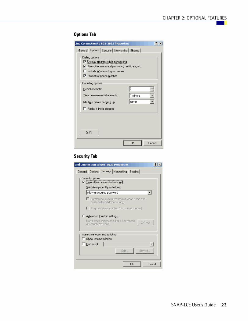
Options Tab
Security Tab
SNAP-LCE User’s Guide 23

CHAPTER 2: OPTIONAL FEATURES
Networking Tab
Sharing Tab
24 SNAP-LCE User’s Guide

CHAPTER 2: OPTIONAL FEATURES
Setting Up a Remote Access Server on the PC (Windows 2000 Advanced Server)Use the following steps to set up a remote access server (RAS) on the PC so that the SNAP-LCE controller can dial in to the PC. Be sure to work closely with your System Administrator.
NOTE: Windows 2000 Professional does not support RAS; you need to have Windows 2000 Advanced Server.
1. In Windows 2000, choose Start➞Programs➞Administrative Tools➞Routing and Remote Access.
2. In the Action pull-down menu, select Add Server. Keep the default to add This Computer as the server. Click OK.
3. Right-click on the server you just added and choose Properties. Click the General tab and choose the following settings:
4. Click the Security tab and set as shown below:
SNAP-LCE User’s Guide 25

CHAPTER 2: OPTIONAL FEATURES
5. Click the Authentication Methods button and set the following, and then click OK:
6. Set the IP tab to use either Static address pool or DHCP server. In this example, we used a Static address pool:
7. Click the PPP tab and make sure nothing is checked.
26 SNAP-LCE User’s Guide

CHAPTER 2: OPTIONAL FEATURES
The NetBEUI and Event Logging tabs are not relevant to the controllerI/O unit's access. You can set them to any level you wish. Since event logging may be useful for troubleshooting the connection, you may want to set it as follows; but it is not required.
To see the log, use the Event Viewer in Administrative tools.
8. Once all tabs are set, click OK. Then highlight the Remote Access Policies branch of the tree. Double-click the only policy that appears in the window to the right. The following window should appear. Make sure that it is set to Grant remote access permission, as shown.
9. Click Edit Profile and click the Authentication tab. Be sure to uncheck everything except Unencrypted Authentication (PAP, SPAP).
10. Click the Encryption tab and set it to No Encryption.
SNAP-LCE User’s Guide 27

CHAPTER 2: OPTIONAL FEATURES
11. Leave the Advanced, IP, and Multilink tabs at their default, which is to default to the server settings.
The Dial-in Constraints permit you to set the server-side idle session timeout and max connect times. These settings are not required, but are useful in some cases.
12. Once all tabs are set, click OK, then click OK again.
The RAS is now ready for the controllerI/O unit to dial in. Have your Network Administrator assign the controllerI/O unit a user name to use for dial-in permission.
Configuring SecurityYou can use ioManager’s Inspect window to set up security on the SNAP-LCE. You can limit access to specific computers or other devices on the network. You can require a password for using FTP. In addition, you can protect an ioControl strategy so that it runs without possibility of interference from a host.
Limiting Access to Specific ComputersYou can limit access to the SNAP controller based on the IP address of the computer or other host device attempting to communicate with it. You specify the IP addresses that may access the controller. Anyone on a computer or other host device with an acceptable IP address has access.
Work with your network administ rator to make sure you are specifying the correct IP addresses.
Limiting Access to Specific ProtocolsYou can also limit access to specific protocols the SNAP controller uses. These protocols can travel simultaneously over the Ethernet/TCP/IP link and set up sessions, or ports, on the SNAP device:
• File transfer protocol (FTP), used for exchanging files between the SNAP-LCE and a computer
• OptoMMP, the IEEE 1394-based memory map protocol, used by most other tools for interfacing with the SNAP device
For security purposes, you can hide or disable one or more of the protocols by changing the port number from its default. The following table shows the default ports.
Protocols for Default Ports:
Protocol Used by Default Port
FTP PCs for file exchange 21
OptoMMP PAC Manager and most other tools 2001
28 SNAP-LCE User’s Guide

CHAPTER 2: OPTIONAL FEATURES
Preventing Access. For example, suppose you want to prevent any device from accessing a controller using FTP. To do so, you would change the port number for the FTP protocol from the default of 21 to zero. Since zero is an invalid port, no device could access the controller using FTP.
Limiting Access. If you wanted to limit FTP access, you could change the port number from 21 to another number between 1 and 65,535. If you change the number, anyone (or any application) that needs to access the controller using FTP can do so by adding the changed port number to the controller’s IP address. For example, if the controller’s IP address is 10.22.56.3 and the port number is changed to 85, you would enter the following to access the controller:
10.22.56.3:85
Requiring a Password for FTPYou can configure security so that anyone who wants to access the device using FTP is required to enter a username and password.
Protecting a PAC Control Strategy from InterferenceYou can set up a SNAP-LCE controller to run a stable strategy without the possibility of interference from a host. This means that no one can alter or stop the strategy using PAC Control or ioTerm; but it also means that ioDisplay cannot communicate with the control engine.
To protect a PAC Control strategy from interference, finalize the strategy, download it, save it to flash memory, and set the autorun flag (see the PAC Control User’s Guide for steps). Then use ioManager to change the Control Engine port number from the default of 22001 to zero, and save that setting to flash as well. The strategy will automatically run when power is turned on, but a host cannot communicate with it.
If you need to change the Control Engine port number back to 22001, you can do so in ioManager, because ioManager uses the OptoMMP protocol to communicate with the controller.
Changing Date and TimeThe SNAP-LCE contains a real-time clock. You can view the clock’s date and time or change it.
NOTE: If you are using ioControl and want to synchronize the I/O unit’s time with your PC’s time, don’t use these steps; instead, follow instructions in Opto 22 form #1300, the ioControl User’s Guide.
1. In the ioManager main window, click the Inspect button .
SNAP-LCE User’s Guide 29

CHAPTER 2: OPTIONAL FEATURES
2. In the IP Address field, type the IP address of the SNAP-LCE controller (or choose it from the drop-down list). Click System and choose Date And Time from the submenu.
3. To change any time or date value, click in the Value field and enter the correct value.
4. When time and date are correct, click Apply to send the values to the controller.
System date and time are set.
30 SNAP-LCE User’s Guide

CHAPTER 3
Chapter 3
Maintenance and Troubleshooting
Maintenance
Assigning an IP AddressSee instructions in Opto 22 form #1440, the ioManager User’s Guide, to assign an IP address to the SNAP-LCE.
Changing the IP AddressIf you know the SNAP-LCE’S IP address, see the ioManager User’s Guide for instructions to change it.
If you do not know the IP address, check the label on the side of the controller. If it’s not there, you can reset the controller to factory defaults (see page 35), or you can follow these steps to find out the IP address using a serial cable:
1. Turn off power to the SNAP-LCE controller. Remove the Ethernet connector.
2. Unscrew the four screws holding on the controller’s top cover and save them. Remove the cover and then carefully slide the board out of its housing.
SNAP-LCE User’s Guide 31

CHAPTER 3: MAINTENANCE AND TROUBLESHOOTING
3. Locate the two jumpers at the bottom of the board, as shown in the following diagram:
4. Using needle-nosed pliers, remove the Boot to Kernel/Loader jumper.
5. Carefully replace the board in its housing and replace the top cover.
6. Connect the controller’s serial port A to the PC via serial cable, following the diagram at right.
7. Turn on power to the controller.
8. Choose Start➞Programs➞Opto 22➞ioProject Software➞ioManager.
The ioManager main window opens.
9. From the Tools menu, choose Install Firmware via Serial Connection to open OptoFlash-ENET:
Boot to Kernel/Loader jumper
Reset to Factory Defaults jumper
Connectors and LEDs at top of board
This diagram shows the controller as it comes from the factory and as it should be for normal operation: the Boot to Kernel/Loader jumper is in and the Reset to Factory Defaults jumper is out.
CONTROLLER
32 SNAP-LCE User’s Guide

CHAPTER 3: MAINTENANCE AND TROUBLESHOOTING
10. Make sure the correct COM port is shown. Choose Device➞Serial Connection.
The utility contacts the controller and displays its IP address, subnet mask, and other information:
11. If you need to change the IP address, subnet mask, or default gateway, type in the new numbers. Make sure they are correct. Then click Store All.
The new data is sent to the controller.
12. Close the dialog box, OptoFlash-ENET, and ioManager. Turn off power to the controller and remove the serial cable.
13. Again remove the controller’s cover and carefully remove the board from its housing. Replace the Boot to Kernel/Loader jumper. Then replace the board and the controller’s cover.
14. Restore power to the controller.
The SNAP-LCE is ready for use. If you changed the IP address, remember to write it on the label on the controller’s case.
SNAP-LCE User’s Guide 33

CHAPTER 3: MAINTENANCE AND TROUBLESHOOTING
Writing Commands to the Controller1. In the ioManager Inspect window, make sure the SNAP-LCE’s IP address is shown. Click
Status Write.
NOTES: The command Restart I/O Unit from powerup will restart the SNAP-LCE controller.
The following Status Write items and Operation Commands do NOT apply to the SNAP-LCE:
2. To send a command to the controller, highlight the command in the list and click Send Command.
For more information on commands, see the ioManager User’s Guide.
Degrees F/CComm Watchdog Time (msec.)Max Digital Scantime (msec)Max Analog Scantime (msec)Reset points to defaultsScanner Flags
Switch to loader modeClear digital event configurationClear alarm configurationClear e-mail configurationClear timer configurationClear PID configurationClear datalog
34 SNAP-LCE User’s Guide

CHAPTER 3: MAINTENANCE AND TROUBLESHOOTING
Resetting the Controller to Factory DefaultsYou can reset a SNAP-LCE to factory default settings if necessary. When you reset the controller, any files, strategy, archived startegy, and persistent variables in RAM and flash memory are erased. The IP address is reset to 0.0.0.0 and the subnet mask to 255.255.255.0.
1. Turn off power to the SNAP-LCE controller. Remove the Ethernet connector.
2. Unscrew the four screws holding on the controller’s top cover and save them. Remove the cover and then carefully slide the board out of its housing.
3. Locate the two jumpers at the bottom of the board, as shown in the following diagram:
4. Using needle-nosed pliers, remove the Boot to Kernel/Loader jumper and put the Reset to Factory Defaults jumper in.
5. Carefully replace the board in its housing and replace the top cover. Turn on power to the controller.
6. Watch the STS LED on the top of the SNAP-LCE. Wait until the solid light goes off; then watch for 14 slow blinks.
The blinks indicate that the controller was successfully reset to defaults. (For other blink codes, see page 45.)
7. Again remove the controller’s cover and carefully remove the board from its housing. Remove the Reset to Factory Defaults jumper and insert the Boot to Kernel/Loader jumper. Then replace the board and the controller’s cover.
The controller is now reset to factory defaults. Its IP address is reset to 0.0.0.0 and its subnet mask to 255.255.255.0.
8. Before restoring power to the SNAP-LCE, follow steps in the ioManager User’s Guide to assign the controller the correct IP address and subnet mask.
Boot to Kernel/Loader jumper
Reset to Factory Defaults jumper
Connectors and LEDs at top of board
This diagram shows the controller as it comes from the factory and as it should be for normal operation: the Boot to Kernel/Loader jumper is in and the Reset to Factory Defaults jumper is out.
SNAP-LCE User’s Guide 35

CHAPTER 3: MAINTENANCE AND TROUBLESHOOTING
Loading New FirmwareEach SNAP-LCE controller contains firmware (sometimes referred to as the kernel), which is similar to an operating system. If the firmware should become damaged, or if you need a newer version of the firmware, you can load new firmware to the controller following instructions in the ioManager User’s Guide.
Replacing the Backup BatteryWhen power to the controller is off, the backup battery can be expected to last about 5 years. When it is time to replace it, follow these steps:
1. Obtain a 3-volt CR2032 Lithium replacement battery.
2. Turn off power to the SNAP-LCE controller. Remove the Ethernet connector.
3. Unscrew the four screws holding on the controller’s top cover and save them. Remove the cover and then carefully slide the board out of its housing.
4. Locate the round, flat battery in the middle of the board, in a black plastic battery holder:
The battery is spring loaded, with the spring on the left in the diagram above.
5. Insert a small screwdriver into the opening on the right-hand side of the battery holder and push the edge of the battery gently to the left to pop the battery out.
6. To insert the new battery, slide it into the holder toward the left, against the spring; then push down gently on the battery to seat it into position.
7. Carefully replace the board in its housing and replace the top cover. Turn on power to the controller.
Connectors and LEDs at top of board
Backup battery in black plastic holderSpring is on this side of holder
Opening in battery holder
36 SNAP-LCE User’s Guide

CHAPTER 3: MAINTENANCE AND TROUBLESHOOTING
TroubleshootingIf you encounter a problem while installing or using the SNAP-LCE controller, check this section for suggestions. See “For Help” on page 4 if you need to contact Opto 22 Product Support.
Communicating with the SNAP-LCE ControllerIf you attempt to connect to the controller using its IP address and you cannot, first check the following:
• Make sure the SNAP-LCE has been turned on and the LNK and RUN LEDs are lit. (See “LED Descriptions” on page 11.)
• Verify that you typed in the correct address for the SNAP-LCE. Check the label on the side of the controller, where the IP address should be written.
• Make sure the controller has been assigned a valid IP address and subnet mask. SNAP-LCE controllers come from the factory with a default IP address of 0.0.0.0, which is invalid. The default subnet mask is 255.255.255.0. To assign IP address and subnet mask, see the ioManager User’s Guide.
• Make sure you have up-to-date drivers installed on your computer’s Network Interface Card (NIC). Contact your system administrator or the manufacturer of the card for help.
• Make sure any firewall in the computer (such as the built-in firewall in Windows XP) is temporarily disabled before you try to assign or change IP addresses, load firmware using ioManager’s Maintenance window, or work with files on the controller. BootP and FTP cannot function through a firewall in the PC. Firewalls in a router are less likely to be a problem unless certain ports (such as FTP client) have been blocked, either by default or on purpose.
Pinging the SNAP-LCE
If you still cannot communicate with the SNAP-LCE after you have checked these items, try to reach it using the PING protocol.
1. Choose Start➞Programs and open a command prompt.
2. At the prompt, type: ping [controller’s IP address]
For example, type: ping 10.192.54.40
If the controller responds, go to “Accessing the SNAP-LCE with ioManager” on page 38.
If the PING command cannot be found, choose Start➞Control Panel➞Network. Make sure TCP/IP is configured as a protocol and that an IP address and subnet mask are assigned.
If you see the message “Destination host route not defined,” the SNAP-LCE probably has an inappropriate IP address and subnet mask. Make sure the IP address and subnet mask on the controller are compatible with those on the computer. Follow directions in the ioManager User’s Guide to check the IP address and subnet mask on the controller and change them if necessary.
SNAP-LCE User’s Guide 37

CHAPTER 3: MAINTENANCE AND TROUBLESHOOTING
If you see the message “No response from host,” check the following:
• Are the computer and controller correctly connected? Is the controller turned on?
• Are the IP address and subnet mask on the controller compatible with those on the computer?
• Is the controller in reset mode? (Check for a blinking STD light. STD blink codes are shown on page 45.)
If you still cannot ping the controller, contact Opto 22 Product Support. (See page 4.)
Accessing the SNAP-LCE with ioManagerOnce you know you can ping the SNAP-LCE, try to access it using ioManager. You will need to know its IP address.
1. If ioManager is not already open, choose Start➞Programs➞Opto 22➞ioProject Software➞ioManager.
The ioManager main window opens:
2. In the ioManager main window, click the Inspect button .
3. In the IP Address field, type the IP address of the SNAP-LCE (or choose it from the drop-down list, if it is there). Click Status Read.
38 SNAP-LCE User’s Guide

CHAPTER 3: MAINTENANCE AND TROUBLESHOOTING
Information from the SNAP-LCE controller is displayed in the window:
If information does not appear, contact Product Support. (See page 4.)
4. Scroll down to see all of the information.
The data is current as of the date and time shown in the Status field at the top right corner of the window. (Note that date and time are from the PC, not from the controller.) To update data, click the Refresh button.
NOTE: The following items in the Status Read area do NOT apply to SNAP-LCE controllers:
5. If you are using PPP for communication through a modem, choose Communications➞PPP Status to see current communication data. (Requires firmware version 5.1c or newer.)
For details on the data shown, see the ioManager User’s Guide.
Degrees F/CComm Watchdog Time (msec.)Scanner FlagsDigital Scan CounterAnalog Scan CounterSmart Modules PresentPID Loops AvailableArcnet Reconfigs Detected
Arcnet Reconfigs Initiated by I/O UnitArcnet Transmit Attempts Since PowerupArcnet ACKsArcnet TimeoutsArcnet OtherArcnet Timeout ValueArcnet Receive InterruptsDig. Output Point Resets Since PowerupDig. Interrupt Failures Since Powerup
Date and time data was last read
Click to update data
SNAP-LCE User’s Guide 39

CHAPTER 3: MAINTENANCE AND TROUBLESHOOTING
Communicating with I/O UnitsIf you have trouble communicating with I/O units, check the Troubleshooting chapter in form #1460, the SNAP Ethernet-Based I/O Units User’s Guide, for suggestions.
Solving Network ProblemsIf problems in communicating with the SNAP-LCE recur, check your network. The wires, switches, and so on in your Ethernet network are not part of the Opto 22 hardware, but any problems in your network may affect communication with Opto 22 products.
Create a Network Diagram
First, create a network diagram and verify the following:
• Cable connectors are firmly inserted.
• The switch has power. Switch LEDs indicate that the connection is up.
• Neither the PC nor the SNAP-LCE uses the switch’s uplink port.
Check Ethernet Errors
Next, use ioManager to check Ethernet errors reported by the SNAP-LCE. These errors indicate network problems. You will need to know the SNAP-LCE’s IP address.
1. Choose Start➞Programs➞Opto 22➞ioProject Software➞ioManager.
2. In the ioManager main window, click the Inspect icon .
3. In the IP Address field, type the IP address of the SNAP-LCE. Click Status Read.
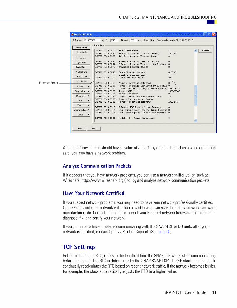
4. Scroll down until you see the items Ethernet Errors: Late Collisions, Ethernet Errors: Excessive Collisions, and Ethernet Errors: Others.
40 SNAP-LCE User’s Guide
CHAPTER 3: MAINTENANCE AND TROUBLESHOOTING
All three of these items should have a value of zero. If any of these items has a value other than zero, you may have a network problem.
Analyze Communication Packets
If it appears that you have network problems, you can use a network sniffer utility, such as Wireshark (http://www.wireshark.org/) to log and analyze network communication packets.
Have Your Network Certified
If you suspect network problems, you may need to have your network professionally certified. Opto 22 does not offer network validation or certification services, but many network hardware manufacturers do. Contact the manufacturer of your Ethernet network hardware to have them diagnose, fix, and certify your network.
If you continue to have problems communicating with the SNAP-LCE or I/O units after your network is certified, contact Opto 22 Product Support. (See page 4.)
TCP SettingsRetransmit timeout (RTO) refers to the length of time the SNAP-LCE waits while communicating before timing out. The RTO is determined by the SNAP SNAP-LCE’s TCP/IP stack, and the stack continually recalculates the RTO based on recent network traffic. If the network becomes busier, for example, the stack automatically adjusts the RTO to a higher value.
Ethernet Errors
SNAP-LCE User’s Guide 41
CHAPTER 3: MAINTENANCE AND TROUBLESHOOTING
If the TCP/IP stack times out while trying to transmit data, it doubles the current RTO and tries again. This process continues for five retries; after that, the controller stops trying and sends a timeout message.
If you are receiving frequent timeout messages from the SNAP-LCE, you can change the TCP parameters in ioManager.
1. Choose Start➞Programs➞Opto 22➞ioProject Software➞ioManager.
2. In the ioManager main window, click the Inspect button .
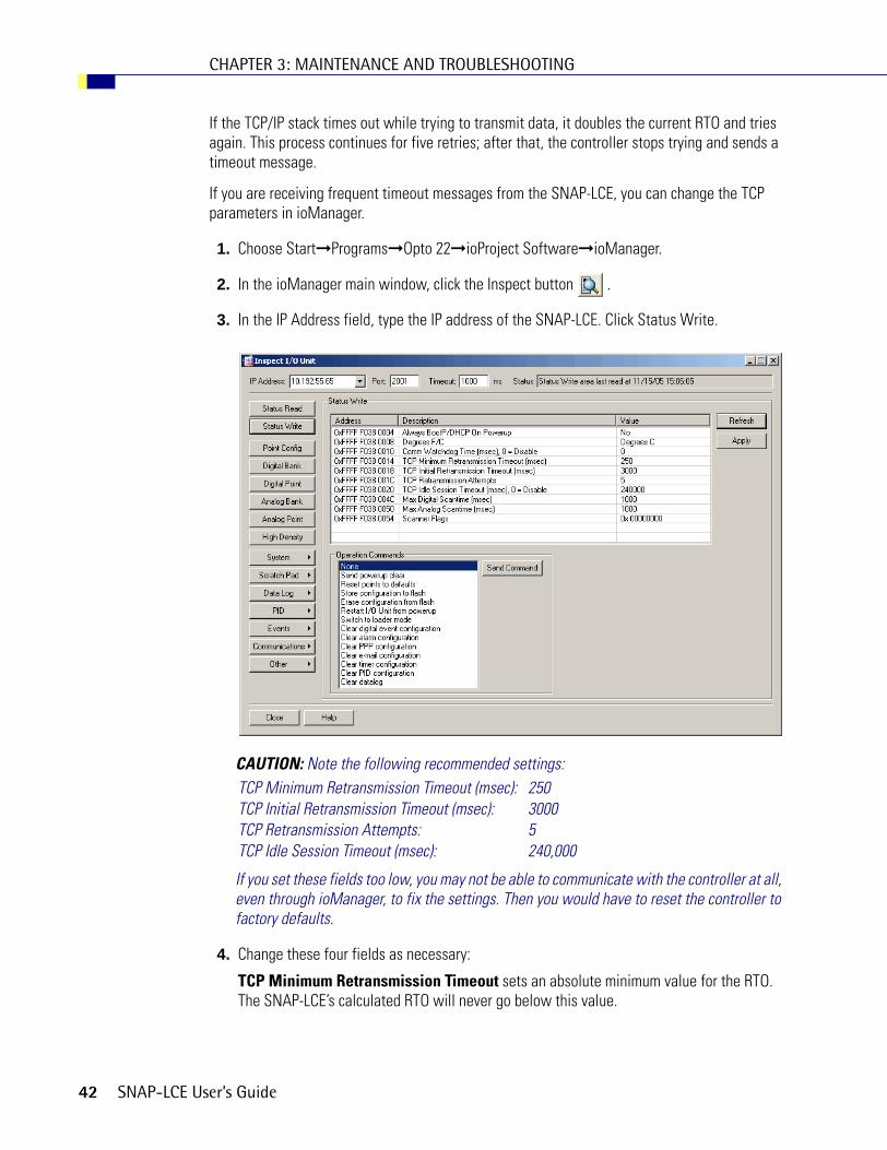
3. In the IP Address field, type the IP address of the SNAP-LCE. Click Status Write.
CAUTION: Note the following recommended settings:
If you set these fields too low, you may not be able to communicate with the controller at all, even through ioManager, to fix the settings. Then you would have to reset the controller to factory defaults.
4. Change these four fields as necessary:
TCP Minimum Retransmission Timeout sets an absolute minimum value for the RTO. The SNAP-LCE’s calculated RTO will never go below this value.
TCP Minimum Retransmission Timeout (msec): 250TCP Initial Retransmission Timeout (msec): 3000TCP Retransmission Attempts: 5TCP Idle Session Timeout (msec): 240,000
42 SNAP-LCE User’s Guide

CHAPTER 3: MAINTENANCE AND TROUBLESHOOTING
TCP Initial Retransmission Timeout sets the RTO for the first communication try. Be careful: since all future tries are based on this value, if you set it too low for network conditions, a connection will never be made.
TCP Retransmission Attempts sets the number of times the SNAP-LCE retries communication. Larger, busier networks need a higher number of retransmits than smaller networks with less traffic.
TCP Idle Session Timeout sets how long (in milliseconds) the SNAP-LCE allows a session to remain open without any activity. After this time, the controller closes the unused session. The default is 240,000 milliseconds, or four minutes.
5. Click the Apply button to write your changes to the SNAP-LCE.
6. In the Operation Commands list, highlight Store configuration to flash. Click Send Command.
7. In the Operation Commands list, highlight Restart I/O Unit from powerup. Click Send Command.
The new TCP parameters are set.
Getting Device and Firmware InformationIf you need to contact Opto 22 Product Support for assistance in using a controller, it is helpful to have device and firmware information at hand before you call us.
1. Choose Start➞Programs➞Opto 22➞ioProject Software➞ioManager.
2. In the ioManager main window, click the Inspect button .
SNAP-LCE User’s Guide 43

CHAPTER 3: MAINTENANCE AND TROUBLESHOOTING
3. In the IP Address field, type the IP address of the device. Click Status Read.
Keep this window open on your screen when you call Product Support.
NOTE: Because the Status Read area is used for both standalone controllers and Ethernet-based I/O units, some items apply to some devices and not others. The following items do not apply to standalone controllers:
For detailed information about items in the Status Read area, see the ioManager User’s Guide.
Degrees F/CComm Watchdog Time (msec.)Scanner FlagsDigital Scan CounterAnalog Scan Counter
PID LoopsSmart Modules PresentArcnet dataDigital resets and failures since powerup
44 SNAP-LCE User’s Guide
CHAPTER 3: MAINTENANCE AND TROUBLESHOOTING
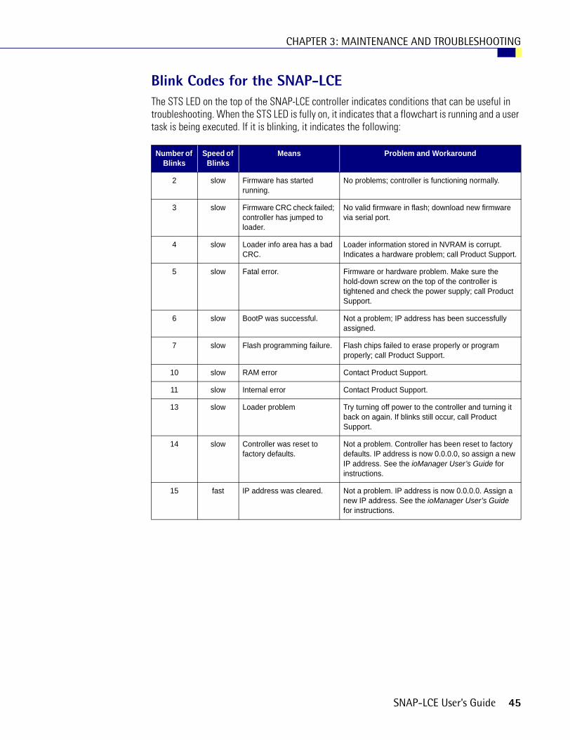
Blink Codes for the SNAP-LCEThe STS LED on the top of the SNAP-LCE controller indicates conditions that can be useful in troubleshooting. When the STS LED is fully on, it indicates that a flowchart is running and a user task is being executed. If it is blinking, it indicates the following:
Number of Blinks
Speed of Blinks
Means Problem and Workaround
2 slow Firmware has started running.
No problems; controller is functioning normally.
3 slow Firmware CRC check failed; controller has jumped to loader.
No valid firmware in flash; download new firmware via serial port.
4 slow Loader info area has a bad CRC.
Loader information stored in NVRAM is corrupt. Indicates a hardware problem; call Product Support.
5 slow Fatal error. Firmware or hardware problem. Make sure the hold-down screw on the top of the controller is tightened and check the power supply; call Product Support.
6 slow BootP was successful. Not a problem; IP address has been successfully assigned.
7 slow Flash programming failure. Flash chips failed to erase properly or program properly; call Product Support.
10 slow RAM error Contact Product Support.
11 slow Internal error Contact Product Support.
13 slow Loader problem Try turning off power to the controller and turning it back on again. If blinks still occur, call Product Support.
14 slow Controller was reset to factory defaults.
Not a problem. Controller has been reset to factory defaults. IP address is now 0.0.0.0, so assign a new IP address. See the ioManager User’s Guide for instructions.
15 fast IP address was cleared. Not a problem. IP address is now 0.0.0.0. Assign a new IP address. See the ioManager User’s Guide for instructions.
SNAP-LCE User’s Guide 45

CHAPTER 3: MAINTENANCE AND TROUBLESHOOTING
About the SNAP-LCE’s Memory MapLike SNAP Ethernet-based brains, the SNAP-LCE uses a memory mapped system for storing data and making that data available to other devices on the Ethernet network. This data includes configuration data, status information about the controller itself, and ioControl strategy variable data that may be needed by a peer on the network.
Although the SNAP-LCE was designed to run ioControl strategies, you can also write your own software applications to communicate with the controller’s memory map, either instead of or in addition to using ioControl. You can use the OptoMMP Communication Toolkit or the IEEE 1394-based protocol for writing your applications. Both are explained in Opto 22 form #1465, the OptoMMP Protocol Guide, which also includes complete details of the memory map. Although this guide is written for I/O units, you can use the same information for the SNAP-LCE. Just be aware that many parts do not apply, since the controller’s memory map doesn’t include any I/O point or related information.
The SNAP-LCE’s memory map includes only the following areas:
Using Data for Peer-to-Peer CommunicationScratch Pad areas within the SNAP-LCE’s memory map provide a way for other devices on the Ethernet network to access data in the SNAP-LCE. For descriptions of the Scratch Pad areas—bits, integers, floats, and strings—see the ioManager User’s Guide.
Using ioControl for Scratch Pad Access
For ioControl commands and examples for accessing Scratch Pad areas, see “I/O Unit—Scratch Pad Commands” in Chapter 10 of the ioControl User’s Guide. You’ll also need to set up the SNAP-LCE to write to its own Scratch Pad. Follow these steps to do so.
1. In ioControl (or ioManager), configure an I/O unit to represent the SNAP-LCE.
a. On the Strategy Tree, doubleclick the I/O units folder. In the Configure I/O Units dialog box, click Add.
b. Enter a name and description (optional). From the Type drop-down list, choose SNAP Mixed 64 Ultimate I/O.
c. In the Primary Address field, enter the SNAP-LCE’s IP address.
Status Area ReadCommunications Port ConfigurationDate and Time ConfigurationStatus Area Write
Security ConfigurationPPP ConfigurationPPP StatusScratch Pad
46 SNAP-LCE User’s Guide

CHAPTER 3: MAINTENANCE AND TROUBLESHOOTING
The dialog box should look something like this:
d. Click OK to add the unit.
2. Use ioControl commands as necessary to write to and read the Scratch Pad areas.
Writing Your Own Applications for Scratch Pad Access
If you are not using ioControl but writing your own software applications to access the Scratch Pad areas, see the OptoMMP Protocol Guide. This guide is written for I/O units, but much of the same information on programming applies to the SNAP-LCE. The Scratch Pad areas of the memory map are described in the programming guide’s appendix; the SNAP-LCE’s Scratch Pad areas are identical to the SNAP Ultimate brain’s.
Choose M64
Enter LCE’s IP address
SNAP-LCE User’s Guide 47

CHAPTER 3: MAINTENANCE AND TROUBLESHOOTING
48 SNAP-LCE User’s Guide

Index
Aarchitectural diagrams, 9
Bbackup battery, replacing, 36battery, replacing, 36blink codes, 45
Cchanging IP address, 31commands, sending, to controller, 34communicating with I/O units, 40communicating with SNAP-LCE
peer-to-peer, 46TCP settings, 41troubleshooting, 37using modem (PPP), 16using serial ports, 13
configuringPPP, 16security, 28serial ports, 13system date and time, 29
control engine port, changing, 29controller
control engine port, 29
Ddate and time, 29dial-up networking
on Windows 2000, 21
DIN-rail mounting, 8disable host communication, 29documentation, related, 3
EEthernet network
certification, 41diagrams, 9errors, 40troubleshooting, 40
Ffactory defaults, resetting SNAP-LCE to, 35file system, 6firmware
getting data about, 43loading, 36
FTP, 6default port, 28limiting access to, 28login, 29password, 29
Hhardware
getting data about, 43installing, 5
helpnetwork problems, 40product support, 4troubleshooting, 37
SNAP-LCE User’s Guide 49

host communication, disabling, 29
II/O units, using SNAP-LCE with, 9IEEE 1394-based protocol
controller’s memory map, 46default port, 28limiting access to, 28
installingDIN-rail mounting instructions, 8hardware, 5panel mounting instructions, 7SNAP-LCE, 5software, 5
ioControl, 2, 3, 6protecting strategy, 29
ioDisplay, 2ioManager
accessing SNAP-LCE, 38description, 2sending commands to controller, 34Status Read page, 38, 43Status Write page, 34
ioProject, 2IP address
assigning, 31changing, 31viewing, 31
IP security, configuring, 28
LLEDs
blink codes, 45description, 11
login for FTP, 29
Mmemory map for SNAP-LCE, 46modem, 16
architectural diagram, 9wiring, 20
mounting the SNAP-LCE, 7
Nnetwork
certification, 41diagrams, 9Ethernet errors, 40OptoEnetSniff, 41troubleshooting, 40
NVRAM, 20
OOpto 22 Product Support, 4OptoEnetSniff, 41OptoMMP
default port, 28limiting access to, 28
OptoOPCServer, 2
Ppanel mounting instructions, 7password
for FTP, 29peer-to-peer communication, 46pinging the SNAP-LCE, 37ports, serial, 13power supply for SNAP-LCE, 10PPP
architectural diagram, 9configuring, 16status, 38
Product Support, 4getting device and firmware data, 43
programming for SNAP-LCE, 6, 46protecting ioControl strategy, 29protocol
default ports, 28limiting access to, 28PPP, 16
Rremote access server (RAS)
Windows 2000, 25remote communication, 16replacing backup battery, 36resetting SNAP-LCE to factory defaults, 35
50 SNAP-LCE User’s Guide

restarting SNAP-LCE, 34retransmit timeout (RTO), 41RS-232, 13
Ssaving configuration to flash, 34Scratch Pad, 46security
FTP login, 29security, configuring, 28serial devices, communicating with, 13serial ports, configuring, 13SNMP
default port, 28software, 2
installing, 5specifications, 10
LEDs, 11power supply, 10
status of SNAP-LCE, 38Status Read page in ioManager, 38, 43Status Write page in ioManager, 34
strategy, protecting, 29system
architecture, 9date and time, 29requirements, 5
TTCP/IP
settings, 41stack, 41
technical support, 4timeout, 41troubleshooting, 37
communicating with I/O units, 40LED blink codes, 45network, 40product support, 4
Uutilities
OptoEnetSniff, 41
SNAP-LCE User’s Guide 51

52 SNAP-LCE User’s Guide