Micha ł Kapa ł ka [email protected] Summer student @ DESY Hamburg

BRAINSSNAP
ANALOG AND DIGITAL
DATA SHEET page 1/19Form 787-000718
Opto 22 � 43044 Business Park Drive � Temecula, CA 92590 � Phone: (909) 695-3000 � (800) 321-OPTO � Fax: (909) 695-3095 � Internet: www.opto22.com
Inside Sales: (800) 452-OPTO � Product Support: (800) TEK-OPTO � (909) 695-3080 � Fax: (909) 695-3017 � E-mail: [email protected] � FaxBack: (800) 474-OPTO
Features• Convenient pluggable connector for removable top mounted
field wiring.• Ready access to standard fuses.• Versatile DIN-rail or panel mounting.• Single distributed brain does it all -
analog, digital, or mixed I/O.• Highly visible LED status indicator for
each channel.• High-density digital I/O
(Four channels per module).• Mix analog and digital modules on
the same rack.• High-density (dual channel
inputs),softwareconfigurable,intelligent analog I/O.
• Handsome snap-on ID plates forchannel labels.
• Quick and easy installation -modules “SNAP” securely onracks, no screws required.
• Factory Mutual approved.
DescriptionThe B3000 is a high-performance brain used to remotely control a mix of both analog and digital I/O modules using Opto 22’s
Snap® “B Series”I/O mounting racks. The B3000 can be used with either an Opto 22 controller or a host computer. On-boardintelligence enables many distributed control functions. Since SNAP analog and digital modules have the same footprint, theB3000 brain can be combined with Snap “B Series” racks to provide the world’s most powerful and sophisticated I/O handlingsystems.
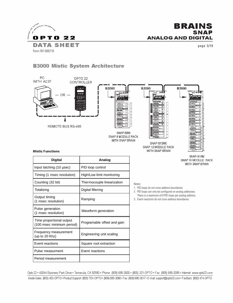
The B3000 communicates with a host processor serially over RS485 twisted pair wiring and supports both the advancedMistic® protocol and the industry-standard Optomux® protocol. Both protocols can support high-speed communication (115 Kbaud).Utilizing the Mistic protocol, advanced I/O processing — including PID calculations (100 millisecond update), pulse width durationmeasurements (100 microsecond resolution), and high-speed counting (20,000 Hz) — can all be accomplished on separate channelsof the same I/O mounting rack. See page 3 for a complete list of mistic functions.
Part Number Description
B3000 SNAP Analog/Digital Brain Mistic/Optomux Protocol

BRAINSSNAP
ANALOG AND DIGITAL
DATA SHEET page 2/19Form 787-000718
Opto 22 � 43044 Business Park Drive � Temecula, CA 92590 � Phone: (909) 695-3000 � (800) 321-OPTO � Fax: (909) 695-3095 � Internet: www.opto22.com
Inside Sales: (800) 452-OPTO � Product Support: (800) TEK-OPTO � (909) 695-3080 � Fax: (909) 695-3017 � E-mail: [email protected] � FaxBack: (800) 474-OPTO
In addition to providing input and output capability, theOptomux protocol also has the ability to perform count, latch,and pulse duration on digital input channels, as well as frequencyand pulse functions on digital outputs. The Optomux protocol isalso capable of providing input averaging and output waveformfunctions on analog channels. See page 4 for a complete list ofOptomux functions.
The B3000 is compatible with the classic B1 and B2 brains,with a few exceptions. The B3000 adds the ability tocommunicate with either a 2-wire or 4-wire configuration, atspeeds of 115 Kbaud. Classic brains were restricted to 4-wirecommunications at up to 38.4 Kbaud. The B3000 now supportsonly the standard 2-pass method of communication with theOptomux protocol.
By using the B3000 with the Mistic protocol and a Misticcontroller, SNAP I/O customers can take advantage ofFactoryFloor®, Opto 22’s impressive new suite of Windows®
32-bit software that delivers total control to industrial automationcustomers. FactoryFloor consists of four integrated components:
• OptoControl™, a graphical, flowchart-baseddevelopment environment for control solutions
• OptoDisplay™, a graphical, multimedia operatorinterface package
• OptoServer™, a robust data server that connects thecontroller network with the PC-based FactoryFloor network.
• Plus OptoConnect™, a drag-and-drop database utilitythat makes building SQL Server and Access databases a snap.
OptoControl is the cornerstone of Opto 22’s FactoryFloorsoftware and is the programming environment that leveragesall the power of Opto 22’s distributed hardware platform.OptoControl utilizes the distributed control capability of theB3000 brain and takes advantage of the graphical Windows95 or NT interface to make it easy to configure, design, andtroubleshoot your control system.
Opto 22’s OptoDriver Toolkit™ may be used for directcommunications from a host PC to the B3000. The toolkitincludes new 32-bit Windows drivers, Windows 16-bit drivers,and Opto 22’s classic DOS drivers. The kit also provides thefiles, documentation, and real-world examples needed to writeMicrosoft® Windows and DOS software applications.Programmers can access the Opto 22 I/O hardware using high-level languages such as Microsoft Visual C++™ or MicrosoftVisual Basic®.
BRAINSSNAP
ANALOG AND DIGITAL
DATA SHEET page 3/19Form 787-000718
Opto 22 � 43044 Business Park Drive � Temecula, CA 92590 � Phone: (909) 695-3000 � (800) 321-OPTO � Fax: (909) 695-3095 � Internet: www.opto22.com
Inside Sales: (800) 452-OPTO � Product Support: (800) TEK-OPTO � (909) 695-3080 � Fax: (909) 695-3017 � E-mail: [email protected] � FaxBack: (800) 474-OPTO
B3000 Mistic System Architecture
Mistic Functions
Notes:1. PID loops do not cross address boundaries.2. PID loops can only be configured on analog addresses.
There is a maximum of 8 PID loops per analog address.3. Event reactions do not cross address boundaries.
Digital Analog
Input latching (10 µsec) PID loop control
Timing (1 msec resolution) High/Low limit monitoring
Counting (32 bit) Thermocouple linearization
Totalizing Digital filtering
Output timing(1 msec resolution)
Ramping
Pulse generation(1 msec resolution)
Waveform generation
Time proportional output(100 msec minimum period)
Programable offset and gain
Frequency measurement(up to 20 Khz)
Engineering unit scaling
Event reactions Square root extraction
Pulse measurment Event reactions
Period measurement

BRAINSSNAP
ANALOG AND DIGITAL
DATA SHEET page 4/19Form 787-000718
Opto 22 � 43044 Business Park Drive � Temecula, CA 92590 � Phone: (909) 695-3000 � (800) 321-OPTO � Fax: (909) 695-3095 � Internet: www.opto22.com
Inside Sales: (800) 452-OPTO � Product Support: (800) TEK-OPTO � (909) 695-3080 � Fax: (909) 695-3017 � E-mail: [email protected] � FaxBack: (800) 474-OPTO
B3000 Optomux System Architecture
Optomux Functions
Digital Analog
Input latching Input Averaging
Time Delays (10ms resolution) High/Low Limit Testing
Pulse Generation (10ms resolution) Waveform Generation
Counting (16 bit) High/Low Limit Recording
Pulse Duration Programmable Offset & Gain
BRAINSSNAP
ANALOG AND DIGITAL
DATA SHEET page 5/19Form 787-000718
Opto 22 � 43044 Business Park Drive � Temecula, CA 92590 � Phone: (909) 695-3000 � (800) 321-OPTO � Fax: (909) 695-3095 � Internet: www.opto22.com
Inside Sales: (800) 452-OPTO � Product Support: (800) TEK-OPTO � (909) 695-3080 � Fax: (909) 695-3017 � E-mail: [email protected] � FaxBack: (800) 474-OPTO
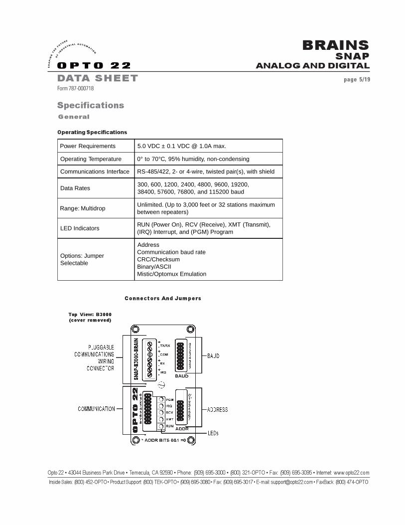
Connectors And Jumpers
Top View: B3000(cover removed)
Operating Specifications
General
Specifications
Power Requirements 5.0 VDC ± 0.1 VDC @ 1.0A max.
Operating Temperature 0° to 70°C, 95% humidity, non-condensing
Communications Interface RS-485/422, 2- or 4-wire, twisted pair(s), with shield
Data Rates300, 600, 1200, 2400, 4800, 9600, 19200,38400, 57600, 76800, and 115200 baud
Range: MultidropUnlimited. (Up to 3,000 feet or 32 stations maximumbetween repeaters)
LED IndicatorsRUN (Power On), RCV (Receive), XMT (Transmit),(IRQ) Interrupt, and (PGM) Program
Options: JumperSelectable
AddressCommunication baud rateCRC/ChecksumBinary/ASCIIMistic/Optomux Emulation
BRAINSSNAP
ANALOG AND DIGITAL
DATA SHEET page 6/19Form 787-000718
Opto 22 � 43044 Business Park Drive � Temecula, CA 92590 � Phone: (909) 695-3000 � (800) 321-OPTO � Fax: (909) 695-3095 � Internet: www.opto22.com
Inside Sales: (800) 452-OPTO � Product Support: (800) TEK-OPTO � (909) 695-3080 � Fax: (909) 695-3017 � E-mail: [email protected] � FaxBack: (800) 474-OPTO
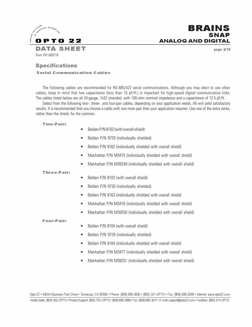
SpecificationsSerial Communication Cables
The following cables are recommended for RS-485/422 serial communications. Although you may elect to use othercables, keep in mind that low capacitance (less than 15 pF/ft.) is important for high-speed digital communication links.The cables listed below are all 24-gauge, 7x32 stranded, with 100-ohm nominal impedance and a capacitance of 12.5 pF/ft.
Select from the following two-, three-, and four-pair cables, depending on your application needs. All will yield satisfactoryresults. It is recommended that you choose a cable with one more pair than your application requires. Use one of the extra wires,rather than the shield, for the common.
Two-Pair:• Belden P/N 8102 (with overall shield)
• Belden P/N 9729 (individually shielded)
• Belden P/N 8162 (individually shielded with overall shield)
• Manhattan P/N M3475 (individually shielded with overall shield)
• Manhattan P/N M39249 (individually shielded with overall shield)
Three-Pair:• Belden P/N 8103 (with overall shield)
• Belden P/N 9730 (individually shielded)
• Belden P/N 8163 (individually shielded with overall shield)
• Manhattan P/N M3476 (individually shielded with overall shield)
• Manhattan P/N M39250 (individually shielded with overall shield)
Four-Pair:• Belden P/N 8104 (with overall shield)
• Belden P/N 9728 (individually shielded)
• Belden P/N 8164 (individually shielded with overall shield)
• Manhattan P/N M3477 (individually shielded with overall shield)
• Manhattan P/N M39251 (individually shielded with overall shield)

BRAINSSNAP
ANALOG AND DIGITAL
DATA SHEET page 7/19Form 787-000718
Opto 22 � 43044 Business Park Drive � Temecula, CA 92590 � Phone: (909) 695-3000 � (800) 321-OPTO � Fax: (909) 695-3095 � Internet: www.opto22.com
Inside Sales: (800) 452-OPTO � Product Support: (800) TEK-OPTO � (909) 695-3080 � Fax: (909) 695-3017 � E-mail: [email protected] � FaxBack: (800) 474-OPTO
IMPORTANT!
TO REMOVE INSULATORFROM CIRCUIT BOARD

BRAINSSNAP
ANALOG AND DIGITAL
DATA SHEET page 8/19Form 787-000718
Opto 22 � 43044 Business Park Drive � Temecula, CA 92590 � Phone: (909) 695-3000 � (800) 321-OPTO � Fax: (909) 695-3095 � Internet: www.opto22.com
Inside Sales: (800) 452-OPTO � Product Support: (800) TEK-OPTO � (909) 695-3080 � Fax: (909) 695-3017 � E-mail: [email protected] � FaxBack: (800) 474-OPTO
CommunicationJumper Descriptions
Communication Jumpers/Wiring
Specifications
Note: When changing jumper settings, thenew settings will not take effect until thenext time the unit is powered up.
Jumper Description
0 Pull-up for TX/RX+
1 Terminator for TX/RX
2 Pull-down for TX/RX-
3 Pull-up for RX+
4 Terminator for RX line
5 Pull-down for RX line
6 Pull-up for IRQ+
7 Terminator for IRQ
8 Pull-down for IRQ-
BRAINSSNAP
ANALOG AND DIGITAL
DATA SHEET page 9/19Form 787-000718
Opto 22 � 43044 Business Park Drive � Temecula, CA 92590 � Phone: (909) 695-3000 � (800) 321-OPTO � Fax: (909) 695-3095 � Internet: www.opto22.com
Inside Sales: (800) 452-OPTO � Product Support: (800) TEK-OPTO � (909) 695-3080 � Fax: (909) 695-3017 � E-mail: [email protected] � FaxBack: (800) 474-OPTO
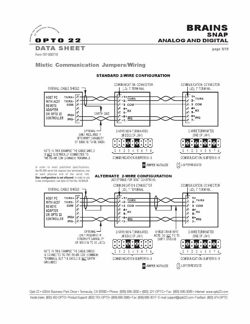
In order to meet published specifications,the RS-485 serial link requires two terminations, oneat each physical end of the serial link.Star configuration is not allowed. In order to usea star configuration, use Opto 22 Part No. AC38A/B.
Mistic Communication Jumpers/Wiring

BRAINSSNAP
ANALOG AND DIGITAL
DATA SHEET page 10/19Form 787-000718
Opto 22 � 43044 Business Park Drive � Temecula, CA 92590 � Phone: (909) 695-3000 � (800) 321-OPTO � Fax: (909) 695-3095 � Internet: www.opto22.com
Inside Sales: (800) 452-OPTO � Product Support: (800) TEK-OPTO � (909) 695-3080 � Fax: (909) 695-3017 � E-mail: [email protected] � FaxBack: (800) 474-OPTO
Mistic Communication Jumpers/Wiring (Continued)
In order to meet published specifications,the RS-485 serial link requires two terminations, oneat each physical end of the serial link. Starconfiguration is not allowed. In order to use astar configuration, use Opto 22 Part No. AC30•A/B.
BRAINSSNAP
ANALOG AND DIGITAL
DATA SHEET page 11/19Form 787-000718
Opto 22 � 43044 Business Park Drive � Temecula, CA 92590 � Phone: (909) 695-3000 � (800) 321-OPTO � Fax: (909) 695-3095 � Internet: www.opto22.com
Inside Sales: (800) 452-OPTO � Product Support: (800) TEK-OPTO � (909) 695-3080 � Fax: (909) 695-3017 � E-mail: [email protected] � FaxBack: (800) 474-OPTO
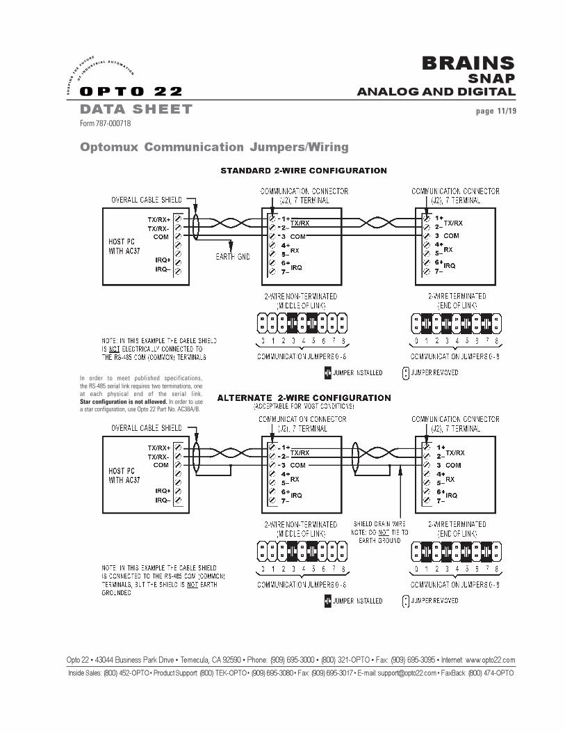
Optomux Communication Jumpers/Wiring
In order to meet published specifications,the RS-485 serial link requires two terminations, oneat each physical end of the serial link.Star configuration is not allowed. In order to usea star configuration, use Opto 22 Part No. AC38A/B.
BRAINSSNAP
ANALOG AND DIGITAL
DATA SHEET page 12/19Form 787-000718
Opto 22 � 43044 Business Park Drive � Temecula, CA 92590 � Phone: (909) 695-3000 � (800) 321-OPTO � Fax: (909) 695-3095 � Internet: www.opto22.com
Inside Sales: (800) 452-OPTO � Product Support: (800) TEK-OPTO � (909) 695-3080 � Fax: (909) 695-3017 � E-mail: [email protected] � FaxBack: (800) 474-OPTO
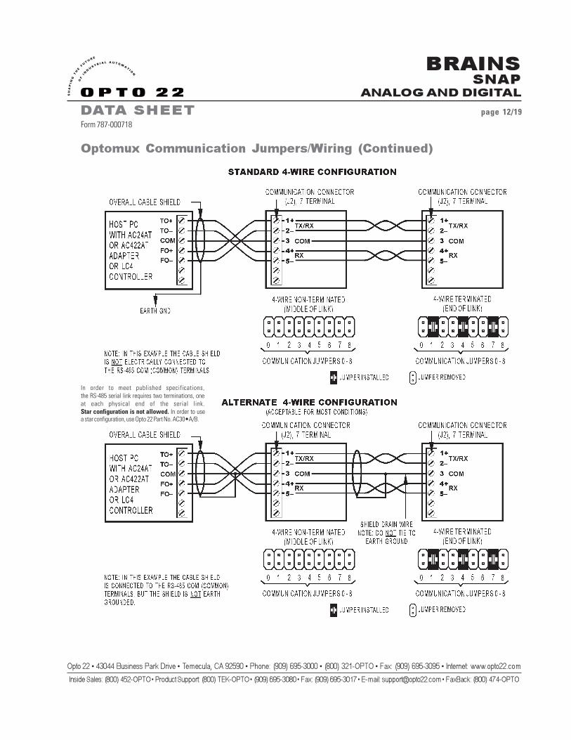
Optomux Communication Jumpers/Wiring (Continued)
In order to meet published specifications,the RS-485 serial link requires two terminations, oneat each physical end of the serial link.Star configuration is not allowed. In order to usea star configuration, use Opto 22 Part No. AC30•A/B.
BRAINSSNAP
ANALOG AND DIGITAL
DATA SHEET page 13/19Form 787-000718
Opto 22 � 43044 Business Park Drive � Temecula, CA 92590 � Phone: (909) 695-3000 � (800) 321-OPTO � Fax: (909) 695-3095 � Internet: www.opto22.com
Inside Sales: (800) 452-OPTO � Product Support: (800) TEK-OPTO � (909) 695-3080 � Fax: (909) 695-3017 � E-mail: [email protected] � FaxBack: (800) 474-OPTO
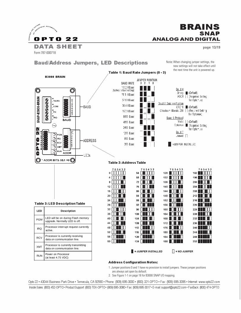
Table 2: Address Table
Table 1: Baud Rate Jumpers (0 - 3)
Table 3: LED Description Table
Address Configuration Notes:
1. Jumper positions 0 and 1 have no provision to install jumpers. These jumper positionsare always set open by default.
2. See Figure 1-1 on page 18 for B3000 SNAP I/O mapping.
B3000 BRAIN
Baud/Address Jumpers, LED Descriptions Note: When changing jumper settings, thenew settings will not take effect untilthe next time the unit is powered up.
LED Description
PGMLED will be on during Flash memoryupgrade. Normally LED is off.
IRQProcessor interrupt request currentlyactive.
RCVProcessor is currently receivingdata on communication line.
XMTProcessor is currently transmittingdata on communication line.
RUNPower on Processor(at least 4.75 VDC)
BRAINSSNAP
ANALOG AND DIGITAL
DATA SHEET page 14/19Form 787-000718
Opto 22 � 43044 Business Park Drive � Temecula, CA 92590 � Phone: (909) 695-3000 � (800) 321-OPTO � Fax: (909) 695-3095 � Internet: www.opto22.com
Inside Sales: (800) 452-OPTO � Product Support: (800) TEK-OPTO � (909) 695-3080 � Fax: (909) 695-3017 � E-mail: [email protected] � FaxBack: (800) 474-OPTO
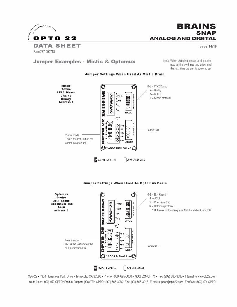
Jumper Examples - Mistic & Optomux
Jumper Settings When Used As Optomux Brain
Jumper Settings When Used As Mistic Brain
Mistic2-wire
115.2 KbaudCRC-16Binary
Address 0
Optomux4-wire
38.4 kbaud checksum 256
Asciiaddress 0
Address 0
2-wire modeThis is the last unit on thecommunication link.
0-3 = 115.2 Kbaud 4 = Binary 5 = CRC 16 6 = Mistic protocol
0-3 = 38.4 Kbaud 4 = ASCII 5 = Checksum 256 6 = Optomux protocol
Address 0
4-wire modeThis is the last unit on thecommunication link.
* Optomux protocol requires ASCII and checksum 256.
Note: When changing jumper settings, thenew settings will not take effect untilthe next time the unit is powered up.

BRAINSSNAP
ANALOG AND DIGITAL
DATA SHEET page 15/19Form 787-000718
Opto 22 � 43044 Business Park Drive � Temecula, CA 92590 � Phone: (909) 695-3000 � (800) 321-OPTO � Fax: (909) 695-3095 � Internet: www.opto22.com
Inside Sales: (800) 452-OPTO � Product Support: (800) TEK-OPTO � (909) 695-3080 � Fax: (909) 695-3017 � E-mail: [email protected] � FaxBack: (800) 474-OPTO
Figure 1-1: SNAP I/O Rack
B3000 I/O Mapping
BRAINSSNAP
ANALOG AND DIGITAL
DATA SHEET page 16/19Form 787-000718
Opto 22 � 43044 Business Park Drive � Temecula, CA 92590 � Phone: (909) 695-3000 � (800) 321-OPTO � Fax: (909) 695-3095 � Internet: www.opto22.com
Inside Sales: (800) 452-OPTO � Product Support: (800) TEK-OPTO � (909) 695-3080 � Fax: (909) 695-3017 � E-mail: [email protected] � FaxBack: (800) 474-OPTO
The B3000 is connected to a SNAP B Series I/O rack,which can hold either 8, 12, or 16 SNAP modules. Digitalmodules (either input or output) contain four channels of I/O. Analog input modules contain two channels and analogoutput modules currently contain two channels. Both analogand digital modules can be on the same rack.
A B3000 is capable of addressing a maximum of 32channels of digital I/O and 32 channels of analog I/O.However, the I/O mounting racks will not accommodate 32channels of both digital and analog. The actual number ofchannels available depend on the combination of moduleschosen. For example, the SNAP-B16M rack can mount 16modules. Up to eight of these modules can be digital,providing 32 channels of digital I/O. The remaining eightmodule positions can be analog, providing up to 16 channelsof analog I/O. If all 16 modules are analog, up to 32 channelsof analog I/O are available.
I/O on the B3000 is divided into four addresses of I/O(two digital I/O and two analog I/O). The digital addressesare base+0 and base+1. The analog addresses are base+2and base+3. Therefore, if a SNAP brain is configured ataddress 12, the digital addresses would be 12 and 13 andthe analog would be 14 and 15.
B3000 I/O Mapping (Continued)
First Four Module Positions (0-3):
Each position can hold either a digital or an analogmodule. They can be all analog, all digital, or any mix of both.These four positions constitute the 16 digital channels of digitaladdress base + 0, and the first eight analog channels ofanalog address base + 2.
Second Four Module Positions (4-7):
Each position can hold either a digital or an analogmodule. They can be all analog, all digital or any mix of both.These four positions constitute the 16 digital channels of digitaladdress base + 1, or the second eight analog channels ofanalog address base + 2.
Third Four Module Positions (8-11):These positions can hold analog modules only. These four
positions constitute the first eight analog channels ofanalog address base + 3.
Fourth Four Module Positions (12-15):These positions can hold analog modules only. These four
positions constitute the second eight analog channels ofanalog address base + 3.
The layout is illustrated in Figure 1-1 on the previous page.

BRAINSSNAP
ANALOG AND DIGITAL
DATA SHEET page 17/19Form 787-000718
Opto 22 � 43044 Business Park Drive � Temecula, CA 92590 � Phone: (909) 695-3000 � (800) 321-OPTO � Fax: (909) 695-3095 � Internet: www.opto22.com
Inside Sales: (800) 452-OPTO � Product Support: (800) TEK-OPTO � (909) 695-3080 � Fax: (909) 695-3017 � E-mail: [email protected] � FaxBack: (800) 474-OPTO
If you configure a digital module on the digital addressbase + 0 at the first module location, that will preclude youfrom configuring an analog module on analog address base +2 at the first module location, as analog channels 0 and 1 ofanalog address base + 2 overlap with digital channels 0,1,2,and 3 of digital address base + 0. This fact will be indicated inOptoControl by text in the Configure I/O Points dialog, whichwill display information in the Name field for analog channels0 and 1 stating that those channels are used by a SNAP digitalmodule, and will specify the name of that I/O unit address.
Digital
When configuring the unit, select B3000 Snap Digital asthe Type in the Add I/O Unit dialog.
The digital addresses are base+0 and base+1. If the SNAPbrain is configured at address 12 (base), the digital addresseswould be 12 and 13 .
When a point is configured, OptoControl automaticallycreates and configures the other three points in the module.For example, if a digital SNAP point is added at channel 5,then identical points are created at channels 4, 6, and 7.Unique names are created for these new points, based on thename entered for the original point. You can then modifythe name, as well as the description, features, default, andwatchdog for each channel independently. If the module typeof one digital point is changed, then the module type of allother points in that module are automatically changed.
OptoControl B3000 SNAP I/O Configuration
AnalogWhen configuring the unit, select B3000 SNAP Analog as the
Type in the Add I/O Unit dialog.
The analog addresses are base+2 and base+3. If the SNAPbrain is configured at address 12 (base), the analog addresses wouldbe 14 and 15.
Inputs:When an input is configured, OptoControl automatically creates
and configures the other input channel on that module. The nameof the other channel can then be modified, as well as the description,default, and watchdog fields. The module type and scaling cannotbe modified.
Outputs:Single-channel analog output modules use two analog channels,
but they contain only one channel of output. Only the even-numberedchannel is usable, e.g., 0, 2, 4, etc. The odd-numbered channel isnot valid. Opto 22 also produces 2-channel analog output modules.
Other Notes
Event/reactions and PID Loops can only operate on points inthe same address group. They behave just like standard I/O in thissense, and cannot cross address boundaries. For example, a PIDloop cannot use an input on Address Base + 2, to control an outputon Base + 3.
Up to 127 event/reactions can be configured per SNAP address.

BRAINSSNAP
ANALOG AND DIGITAL
DATA SHEET page 18/19Form 787-000718
Opto 22 � 43044 Business Park Drive � Temecula, CA 92590 � Phone: (909) 695-3000 � (800) 321-OPTO � Fax: (909) 695-3095 � Internet: www.opto22.com
Inside Sales: (800) 452-OPTO � Product Support: (800) TEK-OPTO � (909) 695-3080 � Fax: (909) 695-3017 � E-mail: [email protected] � FaxBack: (800) 474-OPTO
B3000 I/O Processor
Dimensional Drawings

BRAINSSNAP
ANALOG AND DIGITAL
DATA SHEET page 19/19Form 787-000718
Opto 22 � 43044 Business Park Drive � Temecula, CA 92590 � Phone: (909) 695-3000 � (800) 321-OPTO � Fax: (909) 695-3095 � Internet: www.opto22.com
Inside Sales: (800) 452-OPTO � Product Support: (800) TEK-OPTO � (909) 695-3080 � Fax: (909) 695-3017 � E-mail: [email protected] � FaxBack: (800) 474-OPTO
To install brain onto B Series rack:
1. Turn off power from rack assembly.2. Align brain connector with
mating connector on rack.3. Seat brain onto connector.4. Use integral hold-down screw
to secure in position.DO NOT OVERTIGHTEN!
To remove brain from B Series rack:
1. Turn off power from rack assembly.2. Loosen integral hold-down screw
on brain.3. Pull up on brain.
Brain
Dimension and specifications are subject to change. All products and/or company names throughout this data sheet are generally trademarks or registered trademarks of their respective companies.
Assembly

![Sabeel-e-Sakinaislamicblessings.com/upload/Sallu Alehe Wasallem o... · 2019. 9. 24. · ÷ ^Ûnß ×ô−ß ł i ] çß Ûö ×ôø›ł æł äô nßł × ´ł] çß % × ‚ł](https://static.fdocuments.in/doc/165x107/60fc8f56610aa71794756171/sabeel-e-sakinaislamicblessingscomuploadsallu-alehe-wasallem-o-2019-9.jpg)


![[200.10] Stare druki BARCLAY ą ł ś ł Pozna 1743.](https://static.fdocuments.in/doc/165x107/61790c4780be520a4c29fef2/20010-stare-druki-barclay-pozna-1743.jpg)