
SN3308 Pilot's Guide Rev C - … · BFG WX-500 Stormscope ... In the Flags and Abnormal Conditions...
103
Transcript of SN3308 Pilot's Guide Rev C - … · BFG WX-500 Stormscope ... In the Flags and Abnormal Conditions...

82001-PG-ERR-2.11.doc 7/3/2008 Page 2 of 5
Errata 1. Northstar GPS/Loran: As of this date the Northstar
GPS or Loran will only draw a courseline on the SN3308 when a flight plan is activated. A courseline will not be drawn when using a direct-to. Also, please note that there may be as much as a 30 second delay in auto-slewing on the SN3308 when sequencing waypoints in a Northstar flight plan.
2. BFG WX-500 Stormscope®: The following
information is in addition to that presented in Chapter 3 of the Pilot’s Guide:
a) The indicated strike rate applies only to the visible
area of the display. Zooming in the map range may cause the indicated strike rate to decrease, since active weather areas may no longer be visible.
b) No lightning strikes will be displayed when the
current map range is less than 20 nm. The above items are standard operating features of the WX-500. c) Error messages from the WX-500 are indicated on
the SN3308 are indicated by a message ‘Exx’ where ‘xx’ is a two digit code. Refer to your WX-500 User’s Guide for interpretation.

82001-PG-ERR-2.11.doc 7/3/2008 Page 3 of 5
d) A fatal fault on the WX-500 is indicated by a message ‘FLT’. Please see your authorized Stormscope dealer for service.
3. Back Course Approach Operation:
When flying a back course approach, the course pointer should be set to the published front course. In software versions 2.10 and later, the bottom CDI will automatically reverse sense when the course pointer is more than +/-90 Deg from the lubber line. The label ‘BC’ will appear above the bottom CDI during a back course approach as a reminder to the pilot as shown in the diagram below.
4. Appendix 2: Selected Course and Current Waypoint,
Bearing & Distance callouts are reversed on page A2-4.

82001-PG-ERR-2.11.doc 7/3/2008 Page 4 of 5
5. Page 7-1: For condition of Loss of Gyro and fluxgate, Display Column should read “Compass rose color changes from white to amber.” Applies to version 2.11 software and later.
Revisions from prior revision B2 This information is for informational purposes only. The following items were revised from the previous version of the SN3308 Pilot’s Guide, SPN 82001PG-B2 / 90106PG-B2: All Chapters: • Removed references to radar altimeter. • Color illustrations moved from Appendix 3 to
Appendix 2. • ARC description changed from 90 to 70-degrees. Chapter 1: • Information added about updating the internal database. Chapter 2: • Expanded color list to include new map features. Chapter 3: • Added section on power-up messages. • Revised sections on Map operation. • Clarification of Deviation Bar operation. • Added Displaying the Course Pointer. • Clarification of Auto-Slew operation. • Clarification of Heading Bug operation.

82001-PG-ERR-2.11.doc 7/3/2008 Page 5 of 5
Chapter 4: • Revised map operation. Chapter 5: • Description of enhanced revised map operation. Chapter 6: • Minor clarifications. Chapter 7: • Revised list of abnormal conditions. • List of on-screen messages moved from Appendix 2 to
this chapter. Chapter 8: • Corrected power input current specifications at 13.75
and 27.5VDC. Appendix 2: • New color illustrations of SN3308 display previously in
Appendix 2. Appendix 3: • Deleted.

SIL 3308-10 PG INSERT Page 1 of 2
SN3308 PILOT’S GUIDE INSERT
Ref: Sandel Service Letter 3308-10
Applicability: SN3308 Pilot’s Guide 82001-PG Rev C and previous.
Instructions:
In the Flags and Abnormal Conditions section of the SN3308 Pilot’s Guide update as follows:
1) Under the CONDITION column, line out the words “Fluxgate failure” and replace with FLUXGATE TOTAL ELECTRICAL FAILURE”
2) In the DISPLAY column, to the right of Fast Slave Mode, write “See PG Insert” to refer to the following information:
The following explanation applies when the SN3308 is installed using ‘internal slaving’. This is an installation-selected mode and is used with most remote DG’s such as KG102 or Mid Continent.
A fluxgate is an electronic compass sensor, with most of the characteristics of a wet compass. The fluxgate is the only sensor which provides heading to the SN3308. The remote Directional Gyro turns the SN3308 compass card directly, but does not know which way North is. The fluxgate supplies North and thereby the SN3308 ensures correct compass card orientation, slowly and continually correcting for gyro drift by using the North input from the fluxgate. This correction occurs at 3 deg/minute. It is imperceptible in flight.

SIL 3308-10 PG INSERT Page 2 of 2
The SN3308 has a Fast Slave Mode which turns the card at 25 deg/sec. The heading is redlined during this operation for a minimum of approximately 7 seconds. Fast slave mode normally occurs once per flight when systems are powered up. Fast Slave mode may also occur at any time the Compass Card does not match North from the fluxgate for more than 25 degrees for more than 2 minutes. This delay is incorporated to ensure that no fast-slaving operation occurs during turns, when the fluxgate (like the compass) is not level.
Fast Slaving is an abnormal condition during flight. It can be caused by a defect or error in either the remote gyro, the remote fluxgate, an undetected fault in the SN3308, or aircraft wiring, or from any cause (including all mechanical fluxgate failures) which would allow the compass card and fluxgate heading to stay diverged. If it occurs during flight the card will realign to the fluxgate signal, even if the fluxgate is incorrect.
Fast slaving is automatic. If a fast slave occurs inflight or the compass digits redline, cross-compare the HSI heading to magnetic compass (wet compass) heading with wings level. Pilots normally navigate by flying magnetic track from point to point. Comparing compass heading to actual track is also a good way to detect a compass heading error.
Other systems rely on the SN3500’s heading output and could affect things such as traffic, lightning position, and GPS map displays. If the autopilot is engaged during fast slave the auto-pilot will follow the heading bug or the course pointer and should be disengaged. If there is to be any action taken by the pilot other than disengagement of the autopilot – especially on an approach – ATC should be notified immediately of the system malfunction while simultaneously executing a missed approach and relative heading direction assistance should be requested.

Pilot’s Guide
Document No. 90106-PG Revision C82001-PG Revision C
Publication Date: October 27, 1999
SN3308 Navigational Display

Copyright
Copyright 1999 Sandel Avionics LLC.
All rights reserved. No part of this manual may bereproduced, stored or distributed without writtenpermission of Sandel Avionics, LLC. Additionalcopies of this manual are available from
Sandel Avionics, LLC2401 Dogwood WayVista, CA 92083
Tel: (760) 727-4900Fax: (760) 727-4899
Information in this manual is current as ofpublication or revision date. Specifications andoperational details are subject to change withoutnotice, at the discretion of Sandel Avionics.
The current Pilot’s Guide can also be downloadedfrom the Sandel Avionics website atwww.sandel.com

Revision Notice
The revision and publication date of this Pilot’sGuide is shown on the title page. The effectivityof this Pilot’s Guide to specific software is listedon the cover page of this Pilot’s Guide marked“Effectivity and Errata”.
The “Effectivity and Errata” page:
a) specifically lists the software to which thisPilot’s Guide applies
b) corrects any errors or omissions in thisrevision of the Pilot’s Guide
c) will be reprinted at the time of any newsoftware revisions to approve use of thismanual with the revised software.
Additional copies of the Pilot’s Guide and thelatest revision of the “Effectivity and Errata” pagecan be obtained at the www.sandel.com website.

Approvals
The SN3308 is approved by the FAA as a multi-function display device under
Technical Standard Order (TSO) C-113.
Installation of the SN3308 in a type-certificatedaircraft must be performed in accordance withthe Sandel Avionics SN3308 Installation Manualand is subject to field approval by the FAA.

TABLE OF CONTENTS
C H A P T E R 2
C H A P T E R 1
C H A P T E R 3
Conventions Used in This Manual 1-3
Display Overview
Information Sources 2-1
What is it? 1-1
Welcome to the SN3308
Operational and Legal Issues 1-2
Display Areas 2-1
Indicators 2-2
Data Color Coding 2-3
Operational Basics
Power-up Displays 3-1
Selecting the Data 3-3
Selecting the Primary Nav Source 3-4
Selecting the Bearing Pointer 1 & 2 Nav Source 3-5
Displaying the Map Data 3-5
Displaying Stormscope® Data 3-7

TABLE OF CONTENTS
C H A P T E R 3
C H A P T E R 4
Displaying the Deviation Bar 3-9
Displaying the Course Pointer 3-9
Auto-Slewing the Course Pointer 3-10
Controlling the Display 3-8
Operational Basics – Continued
ARC View and 360˚ View 3-8
Centering the Heading Bug or Needle 3-10
Setting the Map Range 3-10
A-B Function 3-11
Button Operation
NAV 4-1
MAP 4-3
BRG 4-5
SHFT 4-7
SYNC 4-9
A-B 4-11

TABLE OF CONTENTS
C H A P T E R 5
Button Summary 4-19
Sub-Menu Summary 4-20
Enhanced Moving Map Features
UP-ARROW 4-15
DOWN-ARROW 4-13
VUE 4-17
Overview 5-1
Internal Database 5-2
Map Controls and Displays 5-2
Map Memories 5-4
Getting Started – Example 5-6
Map Setup 5-7
Escaping Map Setup 5-9
Setting Other Items 5-9
Copying Settings into Preset Memories 1-4 5-9
Eliminating a Map Memory from the Rotation Sequence 5-10

TABLE OF CONTENTS
C H A P T E R 5
C H A P T E R 6
C H A P T E R 7
C H A P T E R 8
C H A P T E R 9
Automatic Decluttering 5-11
Maximum Range of Internal Map Data 5-11
Quick Map Off 5-12
Adding a Map Memory to the Rotation Sequence 5-10
Enhanced Moving Map Features – Continued
Restoring the Factory Default Map Presets 5-10
Map Auto-Range 5-12
Getting the Most From Your SN3308
Using the HSI 6-1
Bearing Pointers 6-2
Example: Flying an ILS 6-3
Flags, Abnormal Conditions & Messages
Flags & Abnormal Conditions 7-1
Messages 7-3
Technical Specifications & Operating Limits
Installation Information

TABLE OF CONTENTS
A P P E N D I X 1
A P P E N D I X 2
W A R R A N T Y
ARC View A2-2
360 View with Map A2-3
ARC View with Map A2-4
Illustrations
Technology of the SN3308
360 View A2-1
Flags A2-5
Limited Parts & Labor Warranty

Welcome to the SN3308
1
CHAPTER

What is it?For years, pilots of large commercial aircraft have appreciated thebenefits of Electronic Flight Instrumentation Systems, commonlyknown as EFIS. Full EFIS systems combine data from differentsources within the aircraft and provide the pilot with a unified display.This greatly simplifies the instrument scan and improves positionalawareness.
Unfortunately, EFIS is rarely found in smaller General Aviation (GA)cockpits. The cost, complexity, and sheer physical size of most EFISsystems usually relegate them to jets, turboprops, and large piston-engine twins. EFIS screens of 5" x 7" are not uncommon, and thesystem cost can equal or exceed the entire value of a recent-vintageBonanza, for example.
The Sandel Avionics SN3308 packs the essential features of an EFISnav display into a standard three-inch instrument, at a fraction of thecost of a full EFIS. By combining the functions of an HSI, an RMI, amoving map and a Stormscope® display into one instrument, theSN3308 ties together the critical elements of situational awareness.And by adding to that a 3-light marker beacon and GPS annunciatordisplays, the SN3308 becomes the virtual equivalent of an EFIS navdisplay, sized and priced for GA cockpits.
Sandel’s unique electro-optical technology eliminates the unusable areasurrounding the display in most CRT and LCD displays. With a usableimage spanning the entire instrument, the 3-inch SN3308 actuallyprovides more viewing area than most 4-inch CRT displays.
Internally, the SN3308 uses high-speed digital converters to allow itto receive signals from virtually every type of navigation receiver everinstalled in a GA aircraft. A comprehensive set of maintenance pagesallows the installer to simply specify the make and model of theinstalled equipment, and the SN3308 will configure itself accordingly.
The SN3308 shatters the price and size barriers of traditional EFISsystems. With a full-color display and simple, intuitive user interface,the SN3308 brings high-end EFIS functions to the GA cockpit.
1 - 1
1 Welcome to the SN3308C H A P T E R

Operational and Legal IssuesBecause aircraft vary in their installed equipment, it is important tonote that what is displayed on the SN3308 will vary depending onthe presence or absence of equipment such as GPS, Stormscope®,DME, etc. At a minimum, the aircraft equipment should include aheading system (remote directional gyro and fluxgate compass), aVHF (VOR/LOC) nav receiver and a long-range navigation receiversuch as GPS or loran.
Please keep in mind that you are required by Federal AviationRegulations to have on board current charts appropriate to theflight you are undertaking. The moving map on the SN3308 doesnot fulfill this requirement. A current internal database is notrequired but is recommended. The internal database suppliessupplemental data only (such as nearest airports and navaids). IFRflight plan waypoints and courselines are supplied to the SN3308 bythe associated IFR GPS receiver through the receiver’s serial datalink. Supplemental data is intended for positional awareness onlyand should not be used for primary navigation. Check your AircraftFlight Manual Supplement for any additional specific operationalrequirements of your installation.
Also keep in mind that the SN3308 is only a display device; it doesnot determine the aircraft’s heading or sense the aircraft’s position.All information displayed on the SN3308 is generated by externalradios and instruments. It is the pilot’s responsibility to correctlyconfigure and utilize these external devices. The SN3308 is subjectto all legal and operational limitations of the devices supplying itdata. For example, if your GPS receiver is limited to VFR use only,you cannot configure the SN3308 to display only GPS data duringan IFR flight. Always refer to your Aircraft Flight ManualSupplement for any limitations on the use of installed equipment.
1 - 2
1 Welcome to the SN3308C H A P T E R

Conventions Used in This ManualThe name of a button is always placed within square brackets whenthe button is described in text. For example, “...push [SYNC] toalign the heading bug...”
In some cases, the text will describe a two-button sequence, forexample, “...push [SHFT]>[SYNC] to center the needle...”. Thismeans that the buttons are to be pushed consecutively, not heldsimultaneously.
This manual will use terms which should be familiar to aviation-minded readers, such as “selected radial” and “magnetic heading.”Terms which are specific to the SN3308 will be placed in italics, forexample, “lower display area.”
1 - 3
1 Welcome to the SN3308C H A P T E R

Display Overview
2
CHAPTER

Information SourcesThe SN3308 will display data from some or all of the followinginstruments:
■ NAV1 and NAV2 receivers■ DME1 and DME2■ LNAV1 and LNAV2 (GPS or loran)■ Marker beacon receiver■ Weather detection (WX-500 Stormscope®)■ ADF1 and ADF2■ Directional gyro and fluxgate
The following section of the manual describes the appearance of theSN3308 display, and identifies each functional element. Detaileddescriptions of these elements and a tutorial guide to their use arepresented in later sections.
Appendix 2 of this manual contains fold-out pages with full-colorillustrations of SN3308 displays. You may want to fold these pages out for reference while reading this manual.
Display AreasThe primary display area shows either a 360-degree or a 70-degreeARC view, as indicated by the white compass ring. The white airplanerepresents the aircraft’s current position. The primary display areamay also depict the current GPS flight plan, airport, navaids,intersections, airspace and/or Stormscope® data if the map featurehas been enabled. Several indicators (see below) are also presentedwithin the primary display area.
The upper display area presents data from the selected coursenavigation instrument. The actual data displayed depends on thenavigation source (VOR/DME, GPS, or loran) but it will generallyinclude bearing, distance and ground-speed, if available. The upperdisplay area also includes information on the map status, WX-500Stormscope® status (if installed), and an annunciation of whether theVOR nav display is currently receiving either a localizer or a full ILS(localizer/glideslope) signal.
2 - 1
2 Display OverviewC H A P T E R
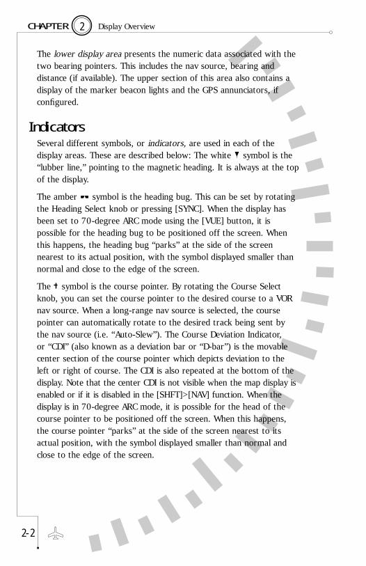
The lower display area presents the numeric data associated with thetwo bearing pointers. This includes the nav source, bearing anddistance (if available). The upper section of this area also contains adisplay of the marker beacon lights and the GPS annunciators, ifconfigured.
IndicatorsSeveral different symbols, or indicators, are used in each of thedisplay areas. These are described below: The white symbol is the“lubber line,” pointing to the magnetic heading. It is always at the topof the display.
The amber symbol is the heading bug. This can be set by rotatingthe Heading Select knob or pressing [SYNC]. When the display hasbeen set to 70-degree ARC mode using the [VUE] button, it ispossible for the heading bug to be positioned off the screen. Whenthis happens, the heading bug “parks” at the side of the screennearest to its actual position, with the symbol displayed smaller thannormal and close to the edge of the screen.
The symbol is the course pointer. By rotating the Course Selectknob, you can set the course pointer to the desired course to a VORnav source. When a long-range nav source is selected, the coursepointer can automatically rotate to the desired track being sent bythe nav source (i.e. “Auto-Slew”). The Course Deviation Indicator, or “CDI” (also known as a deviation bar or “D-bar”) is the movablecenter section of the course pointer which depicts deviation to theleft or right of course. The CDI is also repeated at the bottom of thedisplay. Note that the center CDI is not visible when the map display isenabled or if it is disabled in the [SHFT]>[NAV] function. When thedisplay is in 70-degree ARC mode, it is possible for the head of thecourse pointer to be positioned off the screen. When this happens,the course pointer “parks” at the side of the screen nearest to itsactual position, with the symbol displayed smaller than normal andclose to the edge of the screen.
2 - 2
2 Display OverviewC H A P T E R

The single and double arrow symbols are the two bearingpointers. Depending on user-selected settings, these pointers mayshow the bearing to a VOR, ADF, or GPS waypoint. The numericinformation from the instruments assigned to these pointers isdisplayed in the lower display area. The information is displayed inthe same color as the bearing pointer with which it is associated. Alsonote that the tail of each pointer can be used to determine thebearing from the selected nav source.
Data Color CodingAlphanumeric data displayed on the SN3308 is color coded as follows
2 - 3
2 Display OverviewC H A P T E R
GREEN ■ Stormscope® strike data■ Information associated with the primary
VHF NAV1 receiver (or NAV2 if in co-pilotconfiguration)
■ Certain GPS annunciators: ACTV, AUTOand LEG
■ Class B and C airspace
CYAN ■ Information associated with the LNAV (GPS or loran) receiver(s)
■ GPS annunciators: HLD, PTK and APPR(II Morrow GPS only)
WHITE ■ Compass rose under normal conditions ■ Magnetic heading and button labels■ Airplane symbol representing aircraft’s
current location■ Non-active legs and waypoints of flight plan■ To/From indicator■ Inner marker indicator
RED ■ Flags indicating invalid glideslope or CDI data
■ Prohibited airspace

2 - 4
2 Welcome to the SN3308C H A P T E R
AMBER ■ Heading bug and associated data■ GPS annunciator: MSG and WPT. Also
HOLD (Garmin only)■ Compass rose when either the gyro or
fluxgate has failed■ Middle marker indicator■ Moving map waypoints
YELLOW ■ Information associated with the cross-side NAV receiver (NAV2 if in pilot configuration, NAV1 if in co-pilot configuration)
■ Information associated with the cross-side GPS bearing pointer (GPS2 when navigating on GPS1, GPS1 when navigatingon GPS2)
■ Restricted and warning areas
MAGENTA ■ Active leg and waypoint of flight plan ■ ADF bearing pointer
BLUE ■ Outer marker indicator
PURPLE ■ MOAs

Operational Basics
3
CHAPTER

You can configure and control the SN3308 to provide exactly theinformation you need at any point in the flight. Configuring theSN3308 refers to connecting the appropriate data to a given display.For example, a bearing pointer can be driven by either the VOR orthe GPS receivers. Controlling the SN3308 refers to tailoring thedisplay to suit your information needs. For example, you may decideto turn off a bearing pointer completely during the enroute portion of the flight and use it only during an approach.
Power-up DisplaysOn initial power-up, several different messages may be displayed onthe SN3308. These messages are displayed along the top of thedisplay. Some of the more urgent messages will require youracknowledgement by pressing the flashing [ACK] softkey. (VUE button)
The following messages are displayed on power-up under normalconditions, and do not require acknowledgment.
3 - 1
3 Operational BasicsC H A P T E R
VER xxxxx CRC xxxxxxx ■ Displays the current versionof internal software.
NavData Expires ddmmmmyy, xx ■ Displays the expiration dateof the internal JeppesenNavData database used fordisplaying the moving map.
Lamp xxx Hours Used ■ Indicates the total lampusage in hours and minutes.

3 - 2
3 Operational BasicsC H A P T E R
CRC Self-Test FAILED ■ Program CRC is not theexpected value. The “CRCSelf Test Failed” messagemust not appear on power-up if flight operations arepredicated on the use of theSN3308 Navigational Display.
LAMP CHANGE SUGGESTED ■ Indicates that the internalTEST FAILED xxx HOURS AGO lamp monitoring system has
detected a change in lampcharacteristics and a lampchange is suggested withinthe next 50 hours. Thismessage can only beremoved by replacement ofthe lamp and resetting ofthe lamp monitor by youravionics shop.
TO PERFORM AUTOMATIC LAMP ■ The internal lamp TEST, RUN FOR 2 MINUTES monitoring system AT MAXIMUM BRIGHTNESS periodically tests the
lamp when running at fullbrightness. This messageindicates lack of the test dueto operation below fullbrightness for more than 10hours. Operating the unit atfull brightness for at leasttwo minutes will allow thetest to complete and willremove this message fromthe next power-up cycle.
The following messages may be displayed on power-up and indicatean abnormal situation. These messages will require one or moreacknowledgments by pressing the [ACK] softkey.

3 Operational BasicsC H A P T E R
3 - 3
DEMO MODE: NOT FOR FLIGHT ■ The SN3308 has a special TO EXIT: POWER UP WHILE software mode for use HOLDING NAV-MAP-BRG with the Sandel
demonstrator chassis. Thismessage should neverappear on an instrumentinstalled in an aircraft. Whenin DEMO mode, certaininstallation-specific itemssuch as gyro settings,calibrations, etc. are erased.If the message occurs, donot use the unit for flightuntil it has been reset by anavionics shop and acomplete ground check hasbeen performed.
In addition to these power-up messages, Chapter 7 describes acomplete list of both normal and abnormal messages which can bedisplayed on the SN3308 at any time.
Selecting the DataSensor data is data that comes from various devices within theaircraft. This includes primary navigational instruments such as theVOR, ADF and GPS or loran receivers, as well as instruments such asthe directional gyro (DG), fluxgate compass and Stormscope®.Heading data from the directional gyro and fluxgate compass isalways applied directly to the SN3308’s compass card display, whileother types of sensor data can be displayed in several different ways.You can control these displays by configuring the course pointer, thebearing pointers, the map data and the weather data. See illustrationsin Appendix 2.

Selecting the Primary Nav SourceThe SN3308’s course pointer and CDI (or “D-bar”) can be drivenfrom VOR, GPS or loran data.
In some installations, the [NAV] button on the SN3308 is used toselect the primary nav source. In others, an external switch performsthis function and the [NAV] button has no effect. Refer to yourAircraft Flight Manual Supplement for the details of your installation.If external switching is used, this section does not apply.
If external switching is not used, then pressing the [NAV] buttonrepeatedly will cycle through the available choices, which are specificto your aircraft and were configured by your installer. Selecting aprimary navigation source also connects it to the autopilot, if configured.Numeric data from the primary nav source, such as distance, bearingand groundspeed is displayed in the upper display area. If the selectednav source is a VOR receiver with a localizer frequency tuned, astatus message of “LOC” appears at the upper left of the display as areminder. If a valid glideslope signal is also being detected, the statusmessage changes to “ILS”. The message is turned off if the VORreceiver is tuned to a normal VOR (omni-bearing) frequency.
In some installations, the ILS Lockout function may be enabled on the SN3308. This function forces the selection of the NAV receiverwhen an ILS frequency is selected. Refer to your Aircraft FlightManual Supplement to see whether ILS Lockout has been enabled for your installation.
NOTE: the following ONLY applies if ILS Lockout is enabled:
Tuning the number 1 VOR receiver (NAV1) to an ILS frequency willcause the SN3308 to override the nav source selection and will forceNAV1 as the selected nav source. The nav source will return to theprevious selection after the ILS frequency is de-tuned.
While NAV1 is tuned to an ILS frequency and the nav source selectionoverride is in effect, pressing the [NAV] button will not changesources. Instead, the following message is displayed: “NAV1 TUNEDTO LOC”. To defeat the override and restore the function of the[NAV] button, simply select a non-ILS frequency in the NAV1 receiver.
3 - 4
3 Operational BasicsC H A P T E R

Selecting the Bearing Pointer 1 & 2 Nav SourceThe SN3308 provides two independent bearing pointers which functionin much the same way as a traditional radio magnetic indicator (RMI).The head of each bearing pointer indicates the bearing to the navsource, and the tail of each pointer indicates the bearing from the navsource. Either pointer can be connected to any available navigationsource: VOR, GPS/loran, or ADF. When GPS, loran or other long-rangenav system is selected as the nav source, the bearing pointer indicatesthe bearing to the current active waypoint.
To select which nav sources are connected to either bearing pointer,press [SHFT]>[BRG]. The resulting menus provide choices for eachpointer including nav source, OFF, and AUTO. AUTO will automaticallyselect the same source as that selected for the primary course pointer.The currently selected nav source is bracketed with asterisks (e.g.*AUTO*).
Displaying the Map DataMap data consists of flight-plan waypoints from the LNAV receiver(either GPS or loran), as well as nearby airports, navaids, intersectionsand airspace from the SN3308’s internal database. The map display iscontrolled by pressing the [MAP] button to cycle through the differentmap memory locations and by pressing the [ ] and [ ] buttons tozoom the map in and out. Pressing and holding the [MAP] button for1.5 seconds will turn off both the map display and the WX-500Stormscope display, if enabled.
A map memory is a list of which map items are to be displayed andwhich are not. There are four preset map memories, labeled 1 through4. The factory default settings of the preset map memories are listed inthe table below. There is also a scratchpad memory, labeled “S”, whichyou can change at any time. To save a particular configuration ofscratchpad memory into one of the presets, press [SHFT]>[MAP] andthen [COPY] to select the desired memory location.
To change the display items in the scratchpad memory, press[SHFT]>[MAP]. Move the cursor up and down with the [MAP] and[BRG] buttons, and enable or disable the desired items along thebottom row of the display. The contents of scratchpad memory will beretained until you make further changes, even after cycling the power.
3 - 5
3 Operational BasicsC H A P T E R

For a complete discussion of the SN3308 map features, see Chapter 5.
3 - 6
3 Operational BasicsC H A P T E R
Map Memory Location Factory Defaults
1 Flight plan waypoints and courselines only.
2 Flight plan waypoints and civil airportswith runways>3500 ft. long.
3 Flight plan waypoints and high-level andlow-level VORs.
Note: both the scratchpad memory and the memory location 4 are empty by default and will not show up in the [MAP] button rotation until edited.

Displaying Stormscope® Data
If a BF Goodrich WX-500 lightning detection sensor has been installedin the aircraft, it can be configured to display on the SN3308.
To turn the lightning display on and off, and to control the variousfunctions of the WX-500 sensor, press [SHFT]>[ ] to display therelated softkeys. The available WX-500 functions are listed below. Formore information, refer to the WX-500 User’s Guide.
Lightning strikes are displayed in the SN3308’s primary display area,and are automatically synchronized with the aircraft’s heading. Astatus word in the upper right corner of the SN3308 display isdedicated to the WX-500. In normal operation, this status wordshows the current strike rate, preceded by an “S” for strike mode ora “C” for cell mode.
3 - 7
3 Operational BasicsC H A P T E R
Softkey Label Function
OFF Turns off the Stormscope® display and clears the WX-500 status word.
CELL Selects “CELL” mode, which displays a lightningsymbol for each group of individual strikes.
STRK Puts the WX-500 in “STRIKE” mode, whichdisplays a lightning symbol for each individual strike.
CLEAR Clears the WX-500 of all symbols.
ESC Exits the sub-menu mode.
SETUP MENU Accesses additional WX-500 system commands, seenext page.
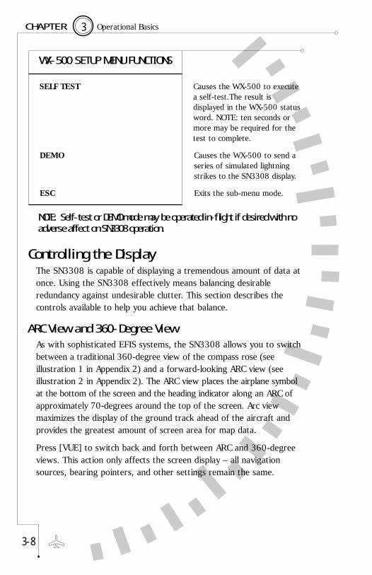
Controlling the DisplayThe SN3308 is capable of displaying a tremendous amount of data atonce. Using the SN3308 effectively means balancing desirableredundancy against undesirable clutter. This section describes thecontrols available to help you achieve that balance.
ARC View and 360-Degree ViewAs with sophisticated EFIS systems, the SN3308 allows you to switchbetween a traditional 360-degree view of the compass rose (seeillustration 1 in Appendix 2) and a forward-looking ARC view (seeillustration 2 in Appendix 2). The ARC view places the airplane symbolat the bottom of the screen and the heading indicator along an ARC ofapproximately 70-degrees around the top of the screen. Arc viewmaximizes the display of the ground track ahead of the aircraft andprovides the greatest amount of screen area for map data.
Press [VUE] to switch back and forth between ARC and 360-degreeviews. This action only affects the screen display – all navigationsources, bearing pointers, and other settings remain the same.
3 - 8
3 Operational BasicsC H A P T E R
WX-500 SETUP MENU FUNCTIONS
SELF TEST Causes the WX-500 to executea self-test.The result isdisplayed in the WX-500 statusword. NOTE: ten seconds ormore may be required for thetest to complete.
DEMO Causes the WX-500 to send aseries of simulated lightningstrikes to the SN3308 display.
ESC Exits the sub-menu mode.
NOTE: Self-test or DEMO mode may be operated in-flight if desired with noadverse affect on SN3308 operation.

Displaying the Deviation BarThe small course deviation bar (or “D-bar”) display in the lowerportion of the screen is visible at all times. In addition, a largerconventional D-bar can be displayed. This D-bar will be displayed onlyunder the following conditions:
■ The “DEV BAR” setting under [SHFT]>[NAV] must be turned ON
■ The map display must be turned OFF ■ The [VUE] mode must be 360-degree view
To turn the map off, press [MAP] until “MAP OFF” appears in theupper right portion of the screen. Note that if the WX-500Stormscope display is turned on, “MAP OFF” will not appear eventhough the map is deselected. To turn off both the map and theStormscope display simultaneously, press and hold the [MAP] buttonfor at least 1.5 seconds.
Displaying the Course PointerThe course pointer itself can be removed from the display to allownavigating on the courseline from your LNAV receiver. Press[SHFT]>[NAV], then the [CRS PTR] softkey to toggle the settingbetween “AUTO” and “ON”.
When set to “ON”, the course pointer is always displayed.
When set to “AUTO”, the course pointer will be turned off under thefollowing conditions:
■ An LNAV receiver (GPS or loran) is selected for navigation, and
■ A waypoint or flight plan is entered, and■ Flight plan waypoints are enabled on the current
map memory.
When NAV is selected for navigation, the course pointer is alwaysdisplayed.
3 - 9
3 Operational BasicsC H A P T E R

Auto-Slewing the Course PointerOne unique feature of the SN3308 is its ability to automatically rotatethe course pointer to the desired course being sent digitally from aGPS or loran. This feature is called “auto-slewing,” and is especiallyuseful during a GPS approach or while flying a complex flight plan.
To enable auto-slewing, press [SHFT]>[NAV], then press the softkeylabeled “AUTO SLEW” to toggle this feature on and off. With auto-slew set “ON”, the course pointer will be set to the desired trackbeing sent by the selected GPS or loran. Turning the course select(OBS) knob has no effect, other than displaying the message“LEG/AUTO (AUTO SLEW) IS ON”. With auto-slew set “OFF”, thecourse select knob rotates the course indicator in the same way as a conventional HSI.
Note that certain GPS receivers such as the King KLN-90B and Garmin GNS 430 support an ‘OBS’ or ‘HOLD’ mode which when active will overrideauto-slew.
Centering the Heading Bug or NeedleTo rapidly set the heading bug to the aircraft’s present heading, press [SYNC]. To rapidly set the course pointer to the current Direct-to course (i.e., to center the CDI), press [SHFT]>[SYNC].
When no valid course is available, such as when flying a LOC/ILSapproach, [SHFT]>[SYNC] rotates the course pointer to the lubberline (current heading) instead.
Setting the Map RangeWhenever map data is being displayed, the [ ] and [ ] buttons areavailable to zoom the image in and out. Each press of either buttonselects the next higher or lower map range. The map range refers tothe depicted distance, in nautical miles, from the airplane symbol tothe outside of the compass tick marks. The current map range isdisplayed at the upper right portion of the screen and is selectablebetween 1 and 1000 nautical miles.
3 - 1 0
3 Operational BasicsC H A P T E R

When either a direct-to waypoint or a full flight plan has been enteredon the LNAV, a one-touch auto-ranging function is available on theSN3308. Pressing and holding the [ ] button for at least 1.5seconds will cause the map range to increase smoothly until reachinga setting at which the entire flight plan is visible. Similarly, pressingand holding the [ ] button for at least 1.5 seconds will set the maprange to a value at which only the current waypoint is visible.
A-B FunctionA unique feature of the SN3308 is its ability to maintain two differentgroups of display settings and to quickly swap back and forthbetween them. This allows you to set up a particular screen displayand memorize the settings for later use. For example, your preferred“enroute” setup might be ARC view with only bearing pointer 1displayed, connected to a VOR navaid. Your “approach” setup mightbe in 360-degree view with bearing pointer 2 displayed, connected toan ADF (to monitor the locator outer marker). In this case, youwould simply set up either display, press [A-B], and then set up theother display. Pressing [A-B] repeatedly will then switch between thetwo displays. The current display setting in use is indicated by theletter “A” or “B” at the top of the screen.
Press [SHFT]>[A-B] to make both displays identical. Whicheverdisplay is visible at the time [SHFT]>[A-B] is pressed will be copiedinto the non-visible display. At this point, pressing [A-B] will have noapparent effect (other than changing the “A” or “B” legend) sinceboth displays have the same content.
3 - 1 1
3 Operational BasicsC H A P T E R

Button Operations
4
CHAPTER

4 - 1
Button Operations Map
4
NAV
NAV
PUSH: Selects the navigational instrument supplyinginformation to the main course indicator, CDI, and upperdisplay area. Each touch of the button cycles through thechoices, which depend on installed equipment andselections made at the time of installation. A typicalsequence is NAV1, GPS1, GPS2. The selected option isdisplayed on-screen next to [NAV]. In some installations,tuning an ILS frequency on NAV1 will override this settingand cause NAV1 to be selected.
NOTE: In some installations, the [NAV] button is disabledand nav source selection is accomplished with an externalswitch. See your Aircraft Flight Manual Supplement formore information.
HOLD: No action performed.
SHFT›NAVDisplays the GPS mode selection switches and nav-relateduser settings.
GPS MODE: Toggles the GPS between “HOLD” (or “OBS”) MODE and “SEQ” (or “LEG”) mode.
GPS ARM: Sends the approach ARM command to the GPS, if configured.
AUTO SLEW: Allows the GPS or loran to automatically rotate the course pointer to the desired track.
CRS PTR: Selects display of the course pointer. When set to AUTO, course pointer will be hidden when LNAV is selected with a current waypoint and flight plan waypoints are enabled on the current map display.
DEV BAR: Selects display of the large horizontal andvertical D-bars in the center of the screen.

4 - 2
Button Operations Map
4
NAV
NAV
Selects primary Nav source.
SHFT›NAV
Invokes “soft keys” that control approach modefunctions of GPS. Also allows for setting of nav-relateduser preferences.
GPS 1
NAV 1
Other
307˚36
307˚
NAV1018˚
ADF1170˚
SYNC A-B
MSG
0
GPS1
27.5 nmBUR 307˚
RNG 75nm250 KT
307˚WXN
AV
VUE
MAP
BRG
N
24
21
W33
3
6
E15 12
30
CRQ
BUR
LAX18
B
++
++++
+
30GPS1
27.5NM
NAV
SHFT
1
N
24
21
W33
3
6
E15 12
30
CRQ
BUR
LAX18
++
++++
+
OFFAUTOSLEW
ONHSIDBAR
ONCRSPTRSYNC A-BSHFT
MSG
GPSMODE
GPSARM
NAV
VUE
MAP
BRG
NAV
Note: Actual softkey labels will vary depending on the GPS receiver used.

4 - 3
Button Operations Map
4
MAP
MAP
PUSH: Controls the display of moving map data. Cyclesthrough the map scratchpad and memories.
HOLD: Turns the map display off. MAP OFF will bedisplayed at the top of the screen.
SHFT›MAP
Accesses the map setup function. See chapter 5 for more detail.

4 - 4
Button Operations Map
4
MAP
MAP
Displays a map memory or turns the map off.Note: When map or weather display is on, CDI will only display on thelower portion of the screen.
307˚36
307˚
NAV1018˚
ADF1170˚
SYNC A-B
MSG
0
GPS1
27.5 nmBUR 307˚
RNG 75nm
RNG 75nm
250 KT
307˚WXN
AV
VUE
MAP
BRG
N
24
21
W33
3
6
E15 12
30
CRQ
BUR
LAX18
B
++
++++
+
SHFT
MAP
24
21
+++
S Scratchpad1 Map Memory 12 Map Memory 23 Map Memory 34 Map Memory 4
COPY
ESC
018˚
SYNC A-B
MSG
NAV
VUE
MAP
BRG
N
24
21
W33
3
6
E15 12
30
CRQ
BUR
LAX18
MAP SETUP 1
++
++++
+
SHFTMIL PRIVCIVIL
Map Setup Items
Airports
Airspace
Intersections
NDBs
VORs
Flight Plan &Waypoints
1
1
*
SHFT›MAP
Accesses the map setup function.

4 - 5
Button Operations Map
4
BRG
BRG
PUSH: Controls the display of the two bearing pointers,and their associated data displays in the lower data area.Each press advances through the following list:
BRG1
BRG2
BOTH
OFF
NOTE: The bearing pointer nav source is pilot selectable(see below). If only one bearing pointer has a nav sourceassigned, pushing [BRG] simply turns the active bearingpointer on and off; if no nav source is assigned to eitherpointer, pushing [BRG] has no effect.
HOLD: Turns both bearing pointers off.
SHFT›BRG
Assigns a nav source (including the option of “OFF”) toeach of the two bearing pointers. Pushing [SHFT]>[BRG]brings up two selection columns, one for each bearingpointer. Each column lists all the available nav sourcesinstalled. Asterisks show the source currently selected.Pressing the buttons below the column steps through thechoices for the bearing pointer. Press the [ESC] softkey toaccept any changes made and exit from the selectionmenus.
NOTE: The “AUTO” option will automatically assign theselected primary nav source to bearing pointer 1.

4 - 6
Button Operations Map
4
BRG
BRG
Turns bearing pointers on/off.
SHFT›BRG
Allows assignment of nav sources to BRG 1 & 2pointers. Currently selected nav source is indicated byasterisk (e.g. *AUTO*).
BRG 1BRG 2BRG 1 & 2Off
307˚36
307˚
NAV1018˚
ADF1170˚
SYNC A-B
MSG
0
GPS1
27.5 nmBUR 307˚
NAV
VUE
MAP
BRG
N
24
21
W33
3
6
E15 12
30
CRQ
BUR
LAX18
B
++
++++
+
SHFT
MSG
BRG
21
RNG 75nm250 KT
307˚WX
1
SYNC A-B
NAV
VUE
MAP
BRG
N
24
21
W33
3
6
E15 12
30
CRQ
BUR
LAX18
B
++
++++
+
OFF*AUTO*NAV1NAV2GPS1ADF1
OFFNAV1NAV2GPS1
*ADF1*
SHFT
MSG
ASSIGN BEARING POINTERS
ESC
A-B
OFFNAV1NAV2GPS1
*ADF1*
15OFF
*AUTO*NAV1NAV2GPS1ADF1
SHFT
SG

4 - 7
Button Operations Map
4
SHFT
SHFT
PUSH: [SHFT] acts as a shift key, permitting access to aselection of sub-menus for certain buttons.
Failure to select a sub-menu for 20 seconds, or pushing[SHFT] a second time cancels the sub-menu access andreturns to a normal display.
HOLD: No action performed.

4 - 8
Button Operations Map
4
SHFT
SHFT
Accesses sub-menus for certain buttons.
N
24
21
W33
3
6
E15 12
30
CRQ
BUR
LAX18
++
++++
+
SHFT
SHFT
GPS Functions,D-BAR, CoursePointer &Auto-SlewSettings
Map setupfunctions
BRG PointerSource selection menu
Centers CDI(When auto-slewdisabled)
WX-500 Stormscope®
functions
Copies currentscreen settingsto both A & B
SYNC A-B
MSG
SELECT SUB FUNCTIONS
NAV
VUE
MAP
WX
NAV
MAP
ESC
ESC
DTKMEMA=B
BRGPTRS
BRG

4 - 9
Button Operations Map
4
SYNC
SYNC
PUSH: Heading sync. Immediately moves the heading bugto the current heading
HOLD: No action performed.
SHFT›SYNC
Course sync. Sets the course pointer “direct-to” thecurrent nav source. If a VOR is the selected nav source,the current radial is chosen as the direct-to courseinformation, and the CDI needle centers with a “TO” flagindication. If the selected nav source is a GPS or loran, this performs the direct-to function if auto-slew is off (see [SHFT]>[NAV]).
If a localizer is tuned, or a received nav signal is too weakto accurately determine the current bearing or the displayis flagged, the course pointer will be turned to the currentheading.

4 - 1 0
Button Operations Map
4
SYNC
SYNC
Sets “Heading Bug” to present heading.
SHFT›SYNC
Rotates course pointer to direct-to, centering CDI. If novalid nav data, turns course pointer to current heading.
SYNC
15 12
SYNC
15 12
307˚36
307˚
NAV1018˚
ADF1170˚
SYNC A-B
MSG
0
GPS1
27.5 nmBUR 307˚
MAP OFF250KT
MAP OFF250KT
307˚NAV
VUE
MAP
BRG
N
24
21
W33
3
6
E15 12
30
B
SHFT
SYNC
DTK
SHFTESC
307˚36
307˚
NAV1018˚
ADF1170˚
SYNC A-B
MSG
0
GPS1
27.5 nmBUR 307˚
307˚NAV
VUE
MAP
BRG
N
24
21
W33
3
6
E15 12
30
B
SHFTDTKESC

4 - 1 1
Button Operations Map
4
A-B
A-B
PUSH: The SN3308 can display either of twopresentations of information, referred to as A and B. [A-B]cycles the display between these two presentationmemories, each of which retains the selected values for:
■ Map range
■ Map selection
■ Bearing pointers ON or OFF
■ [VUE] selection
The only user settings not retained are the primary navsource selection and the actual course pointer and headingbug settings. No user action is required to store changesto A or B. Any change to the above parameters that ismade while A is active become part of A. Any changesmade while B is active become part of B.
Pushing [A-B] swaps the active screen for the inactivescreen. Either A or B is displayed at the top of the displayindicating which memory is currently active.
This two-view option can be used in a wide variety ofways. It can do something as simple as flip-floppingbetween screens that differ only in the map rangedepicted; or it can be used to switch from a simple HSIview to a full EFIS-like display.
HOLD: No action performed.
SHFT›A-B
Copies the active memory into the inactive memory,erasing the previous settings in the inactive memory. (i.e.. If A is active, pressing [SHFT]>[A-B] will copy thesettings in A over to B).

4 - 1 2
Button Operations Map
4
A-B
A-B
Toggles between screen memory A and screen memory B.
SHFT›A-B
Copies active memory into inactive memory.
307˚36
307˚
SYNC A-B
MSG
0
GPS1
27.5 nmBUR 307˚
MAP OFF250 KT
307˚VUE
N
24
21
W33
3
6
E15 12
30
A
SHFT
307˚36
307˚
NAV1018˚
ADF1170˚
SYNC A-B
MSG
0
GPS1
27.5 nmBUR 307˚
NAV
VUE
MAP
BRG
NAV
MAP
BRG
N
24
21
W33
3
6
E15 12
30
CRQ
BUR
LAX18
B
++
++++
+
SHFT
ADF1170˚
A-B
EOM
307˚36
307˚
SYNC A-B
MSG
0
GPS1
27.5 nmBUR 307˚
MAP OFF250 KT
307˚VUE
N
24
21
W33
3
6
E15 12
30
A
SHFT
NAV
MAP
BRG
307˚36
307˚
SYNC A-B
MSG
0
GPS1
27.5 nmBUR 307˚
MAP OFF250 KT
307˚VUE
N
24
21
W33
3
6
E15 12
30
B
SHFT
NAV
MAP
BRG
RNG 75nm250 KT
307˚WX
1

4 - 1 3
Button Operations Map
4
DOWN-ARROW
PUSH: Decreases the map range, in nautical miles, shownon the main display area. Range is always measured fromthe white airplane indicator to the outside of the compasstick marks.
Pushing the [ ] button decreases the map range from1000 nautical miles down to 1 nautical mile. The currentlyselected map range is shown at the top of the display.When the bottom of the map range is reached, furtherpushes of [ ] have no effect.
HOLD: If a flight plan or a direct-to waypoint is active on the LNAV receiver, the map range will auto-scale untilreaching a setting at which the current active waypoint is visible.
SHFT›DOWN-ARROW
No function is performed by this button sequence.
→

4 - 1 4
Button Operations Map
4
Zooms in map range.
6
307˚36
307˚
NAV1018˚
ADF1170˚
SYNC A-B
MSG
0
GPS1
27.5 nmBUR 307˚
NAV
VUE
MAP
BRG
N
24
21
W33
3
6
E15 12
30
CRQ
BUR
LAX18
B
++
++++
+
SHFT
1000nm750nm500nm
2nm1.5nm1nm
RNG 75nm250 KT
307˚WX
1
→
→

4 - 1 5
Button Operations Map
4
UP-ARROW
PUSH: Increases the map range, in nautical miles, shownon the main display area. Range is always measured fromthe white airplane indicator to outside of the compass tickmarks.
Pushing the [ ] button increases the map range from 1nautical mile to 1000 nautical miles. The currently selectedmap range is shown at the top of the display. When thetop of the map range is reached, further pushes of [ ]have no effect.
HOLD: If a flight plan or a direct-to waypoint is active onthe LNAV receiver, the map range will auto-scale untilreaching a setting at which the entire flight plan is visible.
SHFT›UP-ARROW
If a WX-500 Stormscope® lightning detection sensor isconfigured with the SN3308, a softkey is provided toaccess Stormscope functions. Softkeys are labelled withthe following selections: OFF, CELL, STRK, CLEAR andSETUP MENU. Selecting SETUP MENU displays a sub-menu which provides access to the SELF TEST and DEMOfunctions.
If a WX-500 is not present in the system, this buttonsequence has no effect. The message “WX NOTINSTALLED” will be displayed at the top of the screen.
→

4 - 1 6
Button Operations Map
4
Zooms out map range.
Displays softkeys for controlling Stormscope® sensor, ifinstalled.
307˚36
307˚
NAV1018˚
ADF1170˚
SYNC A-B
MSG
0
GPS1
27.5 nmBUR 307˚
NAV
VUE
MAP
BRG
N
24
21
W33
3
6
E15 12
30
CRQ
BUR
LAX18
B
++
++++
+
SHFT
1nm1.5nm2nm
500nm750nm &1000nm
3
SYNC A-B
NAV
VUE
MAP
BRG
N
24
21
W33
3
6
E15 12
30
CRQ
BUR
LAX18
++
++++
+
SHFT
3
BFG STORMSCOPE
ESC
CLEAR
ESC
OFF CELL STRK
SETUPMENU
RNG 75nm250 KT
307˚WX
1
→
→
SHFT› →

4 - 1 7
Button Operations Map
4
VUE
VUE
PUSH: Toggles between displaying a 360-degree compassview and a 70-degree ARC view. Note that in the ARCview, the location of the aircraft is at the bottom of thedisplay. Appendix 2 contains illustrations of 360-degreeview and ARC mode view.
HOLD: No action is performed.
SHFT›VUE
No function is performed by this button sequence.

4 - 1 8
Button Operations Map
4
VUE
VUE
Toggles between 360 and ARC (forward) view.
307˚36
SYNC A-B
MSG
0
GPS1
27.5 nmBUR 307˚
RNG 75nm250 KT
307˚VUE
N
24
21
W33
3
6
E15 12
30
CRQ
LAX
BUR
LAX
BUR
SHFT
NAV1018˚
MSG
NAV1018˚
ADF1170˚
ADF1170˚
NAV
MAP
BRG
B
307˚27.5 nmBUR 307˚
RNG 75nm250 KT
307˚B
360
PL 75nm307˚
VUE
N
AR
310˚310˚
30 33
SYNC ENTSHFT
C
NAV
VUE
MAP
BRG
GPS1
BUR
1 1

Button Summary
The functions associated with each of the nine buttons is summarizedbelow:
4 - 1 9
4 Button Operations MapC H A P T E R
Button Function Performed
VUE Switches between 360-degree compass rose viewand 70-degree ARC mode view.
Increases the range (“zooms out”) on the map andStormscope® displays if either is turned on.
Decreases the range (“zooms in”) on the map andStormscope® displays if either is turned on.
A-B Switches between two groups of screen settings.Allows the pilot to set up two different displays andswap back and forth between them with a singlebutton.
SYNC Moves the heading bug to the top of the display, toalign it with the current aircraft heading.
SHFT Allows access to sub-menu functions.
BRG Turns the bearing pointers on and off. Pressrepeatedly to display pointer 1, pointer 2, both, or“OFF”.
MAP Selects map memory to display or turns it offcompletely.
NAV Selects the nav source to be connected to the HSIcourse pointer, i.e. the primary nav source.

Sub-Menu SummaryThe [SHFT] button accesses a sub-menu mode which provides evenmore functions. The following table summarizes the sub-menufunctions:
4 - 2 0
4 Button Operations MapC H A P T E R
Button SCREEN LABEL FUNCTION PERFORMED
VUE No function performed.
WX Accesses control functions of the WX-500 Stormscope® remote sensor, ifinstalled. Turns Stormscope® displayon or off, clears existing display andallows selection of cell versus strikemode. Also accesses sytem sub-menufor self-test or demo mode.
No function performed.
A-B A=B Copies the current screen settings intothe inactive screen setting memory.
SYNC DTK Performs a course sync, i.e. turns thecourse pointer to the direct-to source.
SHFT ESC (flashing) Cancels the SHFT function.
BRG BRG PTRS Presents source selection for bothbearing pointers.
MAP MAP Accesses map setup functions.
NAV NAV Accesses NAV functions.
Selects approach mode controlbuttons for GPS, if enabeled.
Selects AUTO-SLEW, which allows thelong-range nav source to automaticallyset the course pointer to the desiredtrack.
Controls display of the center D-barfor the CDI and GS needles.

Enhanced Moving Map Features
5
CHAPTER

OverviewMAP operations allow you to display navigation information in theform of a “moving map” directly on the SN3308 display. You haveextensive control over what kinds of navigation information aredisplayed on the map:
■ Airports/Runways■ Controlled and Special Use Airspace■ VORs■ NDBs■ Intersections■ GPS Flight Plans (with or without course line)
Within each of these classes of map objects you may fine tune exactlywhich items you want displayed. For example, you may choose toexclude military or private airports, or those with unpaved runwaysor runways shorter than a particular length. Similarly, you may electnot to display terminal VORs or low-powered NDBs, or to displayClass B airspace and Restricted Areas but exclude Class C airspace andMOAs. As you’ll see, the SN3308 offers great flexibility in how youconfigure your moving map display.
Finally, you may store up to four different map configurations, andthen quickly switch from one to another as appropriate to your phaseof flight. For instance, when cruising at FL180 or higher, you mightwant to display only high-altitude VORs (but not Terminal or Low-altitude VORs), Special Use Airspace (but not Class B or Class C), andonly airports with paved runways of 6,000 feet or longer. TheSN3308 allows you to save such a map configuration in one of itsfour map memories and then recall it as needed.
All the airports, navaids and intersections on the moving map, exceptfor GPS flight plan fixes, come from the internal database of theSN3308 and are color-coded amber. GPS flight plan fixes come fromthe GPS receiver and are color-coded magenta/white. Controlled andSpecial Use Airspace also comes from the internal database, and arecolor-coded according to its type (Class C and Class B in green, MOAsin purple, Restricted and Warning Areas in yellow, and ProhibitedAreas in red).
5 - 1
5 Enhanced Moving Map FeaturesC H A P T E R

Note: The SN3308 requires a connection to a GPS receiver in order to displaythe moving map. The map display, including the flight plan from the GPS1receiver, will also be shown when NAV1 or NAV2 is selected as the primaryNav source.
Internal DatabaseNon-flight plan data including airspace is referred to as the “internaldatabase” and is stored in the SN3308’s internal memory. Theinternal database can be periodically updated from a Windows-basedPC or laptop. The expiration date of the internal database is shownduring the power on sequence. As this database is for supplementaluse only and not intended for primary navigation, it is not required to be kept up to date. Database updates are available directly fromSandel Avionics, and may be purchased online at www.sandel.com.
Newly manufactured units may not contain an internal database whenshipped from the factory. Your avionics installer should obtain andinstall the most recent database prior to completion of a newinstallation. The SN3308 will operate normally without an internaldatabase except that only GPS flight plan waypoint information willthen be displayed.
Map Controls and DisplaysInformation associated with control of the map is displayed as follows:
■ The map status bar is shown just to the right of the MAP button and shows icons for the currently enabled map items.
■ The map memory location currently being displayed is shown at the top of the map status bar as “S”, “1” “2” “3” or “4”.
■ The map range (or “MAP OFF”) is shown in the upper right of the display.
5 - 2
5 Enhanced Moving Map FeaturesC H A P T E R

Map operations are controlled with the following buttons:
■ [MAP] – Press repeatedly to cycle through the map memoriesincluding MAP OFF. Holding the [MAP] button will turn off the map without cycling through the memory locations.
■ [ ] and [ ] – Press to zoom the map range in or out. Holding the [ ] button auto-ranges to the current waypoint and holding the [ ] button auto-ranges to the end of the current flight plan.
■ [SHFT]>[MAP] – Accesses the map setup function and allows enabling or disabling of various map items.
5 - 3
5 Enhanced Moving Map FeaturesC H A P T E R
307˚36
307˚
NAV1018˚
ADF1170˚
SYNC A-B
MSG
0
GPS1
27.5 nmBUR 307˚
RNG 75nm250 KT
307˚WXN
AV
VUE
MAP
BRG
N
24
21
W33
3
6
E15 12
30
CRQ
BUR
LAX18
B
++
++++
+
SHFT
1
Map memorycurrentlydisplayed
Cycles throughmap memories
Map status bar
Current maprange
Increasesmap range
Decreasesmap range

5 - 4
5 Enhanced Moving Map FeaturesC H A P T E R
Map MemoriesThe [MAP] pushbutton cycles from MAP OFF through a maximum offour possible map memory locations, or memories, plus a scratchpadmemory. The map memory you are currently displaying is shown atthe top of the map status bar and will show S, 1, 2, 3 or 4.
Any memory which is empty is skipped during the MAP rotationsequence. In the default setup of the SN3308, memories 1, 2 and 3contain factory settings, and memories S and 4 are empty.
Map memory S has been designated the scratchpad memory and theremaining memories 1-4 are designated as preset memories. All on-screen changes are made to S but can be copied to memories 1-4 asdesired. The purpose of having a separate scratchpad is to allow youto quickly add or delete items from your map display to attend to acurrent flight situation, without changing presets you may alreadyhave made.
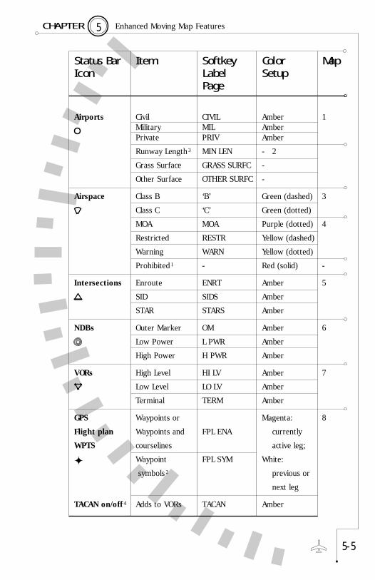
The map setup function, described on page 5-7, shows how to makechanges to the map memories. The following table lists the 24 itemsthat can be independently configured for each map memory:
There are a large number of selection items. However, the organizationof the SN3308 is intended to make the map setup process as easy aspossible. You should experiment often with the map settings until youdevelop the style of operation best suited to your flying.
5 - 5
5 Enhanced Moving Map FeaturesC H A P T E R
Status Bar Item Softkey Color Map Icon Label Setup
Page
Airports Civil CIVIL Amber 1Military MIL AmberPrivate PRIV Amber
Runway Length3 MIN LEN - 2
Grass Surface GRASS SURFC -
Other Surface OTHER SURFC -
Airspace Class B ‘B’ Green (dashed) 3
Class C ‘C’ Green (dotted)
MOA MOA Purple (dotted) 4
Restricted RESTR Yellow (dashed)
Warning WARN Yellow (dotted)
Prohibited1 - Red (solid) -
Intersections Enroute ENRT Amber 5
SID SIDS Amber
STAR STARS Amber
NDBs Outer Marker OM Amber 6
Low Power L PWR Amber
High Power H PWR Amber
VORs High Level HI LV Amber 7
Low Level LO LV Amber
Terminal TERM Amber
GPS Waypoints or Magenta: 8
Flight plan Waypoints and FPL ENA currently
WPTS courselines active leg;
Waypoint FPL SYM White:
symbols 2 previous or
next leg
TACAN on/off 4 Adds to VORs TACAN Amber

Getting Started – ExampleThe Factory Default SN3308 map memories are set up as follows:
S: Empty
1: Flight plan only with courselines
2: Flight plan and paved civil airports over 3500' in length
3: Flight plan and HI and LO VORs
4: Empty
To get started, we recommend you try some operations on theground. Ensure that your GPS receiver is operating, and enter a flightplan using its normal procedures. You can use the simulator mode ofyour GPS receiver if it has one, or if it does not, make sure the flightplan you enter is near the airport where you are located.
Press [MAP] until “1” shows at the top of the map status bar. Withthis setting, you should see the waypoint icon next to the [MAP]key, indicating that flight plan waypoints are enabled on the display.Use the [ ] or [ ] key to adjust the display range, which is thenumber of miles between the symbolic airplane and the outercompass ring. You should see your GPS flight plan on the display. The active leg andwaypoint will be shown in magenta and the other waypoints andcourselines will be shown in white.
5 - 6
5 Enhanced Moving Map FeaturesC H A P T E R
1 Prohibited airspace is shown in Red and cannot be turned off on themap display.
2 Flight plan waypoints can be selected to show as facility icons (such asVOR or INT icons) or to show as waypoint icons only using mapsetup page 8. Most RS-232 GPS receivers are limited to showingwaypoint icons only.
3 Runways below a selectable minimum length may be masked from thedisplay by pressing the MIN LEN softkey. This parameter may be setto 2000', 2500', 3000', 3500', 4500', 5500', 6500' or ALL.
4 TACAN is a single setting which will affect all of the map memories.This can be set from within any map memory and will affect all mapdisplays.

Set the map range to 30 nm, and press [MAP] so that “2” is displayed.The display should show your flight plan as above, overlaid with localairports with runways over 3500'. Note that the airport icon showson the map status bar indicating airports are being displayed, andthat on-screen airports are shown in amber. The amber colorindicates that the source of the airport data is coming from theinternal database. The flight plan information, coming from the GPSreceiver, is displayed in magenta and white.
Lower the map range to 10nm, and notice that as the display zoomsin any airport shown will change from the airport icon into a runway(or multiple runways). Below 7nm the runway numbers will also beadded so that as you zoom in you can plainly see the airportidentifier, runways, and runway numbers. During flight, the displaywill rotate and update with the aircraft in real-time.
Press [MAP] to change to memory 3. Notice that airports will beremoved and instead local LO and HI VORs will be shown in Amber.Note that on the map status bar the airport icon will be removed andthe VOR icon will display, indicating that VORs are enabled.
Pressing [MAP] again will skip memory 4, because it is empty, andjump directly to MAP OFF. All the map information will be removedfrom the screen. Further presses of the [MAP] key will again cyclethrough map memories 1, 2 and 3 and then back to MAP OFF.
Map SetupWe are about to change what is displayed on the map, using memory1 as the baseline. Start by pressing [MAP] until “1” shows at the topof the map status bar.
Press [SHFT]>[MAP] to enter Map Setup. All settings in memory 1are copied to S (the scratchpad memory), and you can now makenon-permanent changes with the softkeys. Notice that you are editingmemory S. If you want to save these changes back into memory 1,you can use the COPY function, described on page 5-9.
5 - 7
5 Enhanced Moving Map FeaturesC H A P T E R
Map setup allows you to change the scratchpad memory S by addingor deleting items from the map category by category. The twobuttons located next to the map status are used to move the mapstatus cursor up and down, selecting the different map setup itemsyou want to change.
Notice that when you select each setup item, the three softkeys at thebottom of the screen change and are used to make your selections.The [ ] or [ ] keys continue to function normally so you canchange the map range during setup operations to see the effect ofyour changes.
For example, highlight the Airspace icon on the map status bar, andthen use softkeys ‘B’ and ‘C’ to enable airspace depiction and observe
5 - 8
5 Enhanced Moving Map FeaturesC H A P T E R
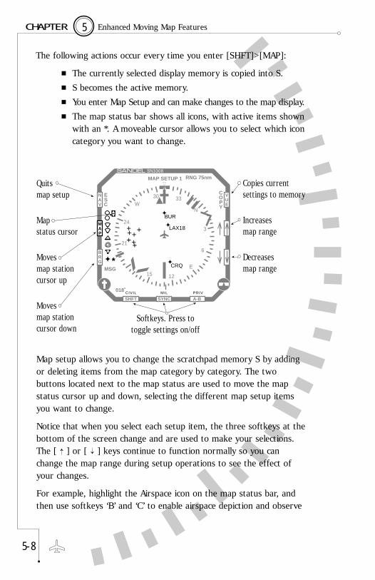
The following actions occur every time you enter [SHFT]>[MAP]:
■ The currently selected display memory is copied into S.■ S becomes the active memory.■ You enter Map Setup and can make changes to the map display.■ The map status bar shows all icons, with active items shown
with an *. A moveable cursor allows you to select which iconcategory you want to change.
COPY
ESC
018˚
SYNC A-B
MSG
NAV
VUE
MAP
BRG
N
24
21
W33
3
6
E15 12
30
CRQ
BUR
LAX18
MAP SETUP 1
++
++++
+
SHFTMIL PRIVCIVIL
Quits map setup
Map status cursor
Moves map stationcursor up
Moves map stationcursor down
Copies currentsettings to memory
Increasesmap range
Decreasesmap range
Softkeys. Press totoggle settings on/off
RNG 75nm
*

the map display. Assuming you are in a location with nearby Class Bor C airspace, you should see the airspace boundaries on your display.Notice that you are displaying scratchpad memory S, and you haveadded airspace depiction.
Note: During map setup operations the SN3308 continues to operatenormally. The compass and deviation displays are still active, and the HDGand CRS knobs still operate.
Escaping Map Setup Note the flashing ESC softkey. Pressing this softkey will immediatelyexit the map setup page, and the map display will remain as youprogrammed it. You should see both your flight plan and airspace onthe map display.
Setting Other Items Using [SHFT]>[MAP] again, try changing other items on differentmap setup pages and observe their effects. Note that you are notchanging memories 1-4 by these actions. In fact, if during normaloperation you are displaying any memory 1-4, you can press[SHFT]>[MAP] to create a new baseline for the scratchpad memory.
Copying Settings into Preset Memories 1-4Map settings can be retained for future use by storing them into oneof the four memory presets. This is done by copying the scratchpadmemory into one of the presets using the COPY function.
■ Press [SHFT]>[MAP] to access the map setup function and adjust the settings as desired.
■ Press the COPY softkey.■ Press one of the memory softkeys (1-4) to copy the
scratchpad into that memory. (To exit without saving, press the QUIT COPY softkey.)
■ Press the ESC softkey to exit the map setup function.
The changes made during map setup are now stored in the memorypreset you chose and can be recalled during the map rotation.
5 - 9
5 Enhanced Moving Map FeaturesC H A P T E R

Eliminating a Map Memory from the Rotation Sequence
You may choose to have fewer than 4 map presets to reduce thenumber of memories in the MAP key rotation sequence. You caneliminate a preset memory by deleting all items in that memory.
■ Press [SHFT]>[MAP] to access the map setup function.■ Press the COPY softkey.■ Clear the scratchpad memory by pressing the CLEAR
softkey. The message ‘SCRATCHPAD CLEARED’ will be shown briefly at the top of the display.
■ Press the softkey of the preset memory you desire to skip.■ Press the ESC softkey to exit the map setup function.
Both the scratchpad memory and the memory preset you cleared willnow be skipped in the map rotation.
Adding a Map Memory to the Rotation SequenceYou may bring an empty preset memory back into the MAP keyrotation sequence by copying the scratchpad memory into it.
■ Press [SHFT]>[MAP] to access the map setup function and adjust the settings as desired.
■ Press the COPY softkey.■ Press one of the memory softkeys (1-4) to copy the
scratchpad into that memory.■ Press the ESC softkey to exit the map setup function.
The memory preset you chose is now added to the map rotation.
Restoring the Factory Default Map PresetsThe factory default map presets may be restored at any time. Notethat this will permanently erase any information you have enteredinto the preset memories.
■ Press [SHFT]>[MAP] to access the map setup function. ■ Press the COPY softkey.
5 - 1 0
5 Enhanced Moving Map FeaturesC H A P T E R

■ Press and hold the CLEAR (HOLD DFLT) softkey at least `four seconds. The message ‘DEFAULT MEMORIES 1 TO 4' will be shown at the top of the display.
Factory defaults will be loaded into presets 1-4 as follows:
S: Empty (skipped)
1: Flight plan only with courselines
2: Flight plan and paved civil airports over 3500' in length
3: Flight plan and HI and LO VORs
4: Empty (skipped)
Automatic DeclutteringIt is possible for the SN3308 map display to become too cluttered toread, such as by turning on all possible map items. This also has theundesirable side effect of slowing down the display update rate.
The SN3308 will automatically remove items from the display if thetotal number of items is too great to display. When this occurs, it isindicated by a color change in the associated icon in the map statusbar. Normally these icons are amber, but any item which is notshowing all possible occurrences because of an automatic declutteringwill change the icon color to yellow.
Normally the SN3308 will allow up to approximately 50 icons beforethis action occurs, but this number may be smaller if complex airspaceis simultaneously being displayed. When auto-decluttering occurs, itoccurs first to the objects closest to the aircraft. When the display iszoomed-in, these objects will reappear and the associated status baricon will turn back to amber.
Maximum Range of Internal Map DataDuring normal operation, the SN3308 only displays items from itsinternal database which are within 150 nm of the current aircraftposition (300nm for VORs), even when the selected range is larger.
5 - 1 1
5 Enhanced Moving Map FeaturesC H A P T E R
Quick Map OffDuring normal operation press and hold the [MAP] key. After 1.5seconds the map display will jump to MAP OFF from any memory.You can use this feature to quickly remove all map data from thescreen at any time. Note that this feature will also turn off the WX-500 Stormscope display, if enabled.
Map Auto-RangeThe SN3308 provides a one-touch automatic ranging function.Pressing and holding the [ ] key for 1.5 seconds will cause theSN3308 to zoom to the lowest map range at which the currentwaypoint is still visible. Conversely, pressing and holding the [ ] keywill zoom to the highest setting needed to display the full flight plan.
5 - 1 2
5 Enhanced Moving Map FeaturesC H A P T E R
Getting the Most From Your SN3308
6
CHAPTER

If you have never flown with an HSI, you’ll find that the combinationof heading information and selected nav course is a powerful tool. Ifyou have never flown with an RMI, you’ll find that a simple bearingpointer can greatly improve your situational awareness. And if youhave never flown with an SN3308, with its combination of HSI, RMIand moving map in a single display, you’re about to discover how thewhole can be greater than the sum of its parts. Please refer to thecolor fold-out pages of this manual while reviewing the following.
Using the HSIA horizontal situation indicator (HSI) is basically a VOR needlesuperimposed over a directional gyro (DG) ring, or heading indicator.On a conventional VOR display, a course deviation indicator (CDI)indicates left or right deviation, and an Omni-Bearing Select (OBS)knob allows selection of the desired course. On an HSI, the OBS knobturns a course pointer which rotates until it is pointing to the desiredcourse on the DG ring. The center section of the course pointerswings left and right to perform the CDI function. A glideslope(vertical deviation) scale is displayed on the right side of the coursepointer, and the TO/FROM flag is a white triangle displayed next tothe course pointer, either above or below the CDI.
By using the heading indicator as a background for the entire coursepointer/CDI combination, an HSI gives you an immediate visual indicationof the location of the desired radial. You can see at a glance yourintercept angle to the desired radial, whether or not you have flownthrough the radial, and whether you are tracking inbound or outbound.
In normal operations, you should connect the HSI course pointer toyour primary navigation source. Do this by pressing the [NAV] buttonuntil the desired source is annunciated.
When the nav source is a VOR receiver, turn the OBS knob until thecourse pointer is set to the desired radial. To immediately center theneedle and proceed DIRECTLY TO the VOR station, press[SHFT]>[SYNC]. If the receiver is tuned to a localizer frequency, setthe course pointer to the published inbound course. Even though theOBS setting doesn’t affect the CDI when a localizer is tuned, it is very
6 - 1
6 Getting the Most From Your SN3308C H A P T E R
important to maintain the correct visual orientation on the HSI.In addition, the autopilot will be using the OBS to obtain a coursereference. Pressing [SHFT]>[SYNC] when a localizer frequency istuned rotates the course pointer to align with the present heading.
When the nav source is a long-range nav receiver such as GPS orloran, the SN3308’s course pointer can auto-slew, orautomatically point to the correct course. The auto-slew functioncan be enabled or disabled by pressing [SHFT]>[NAV] andtoggling the AUTO SLEW softkey. If enabled, when the navreceiver sequences to subsequent waypoints on a flight plan or anapproach, the course pointer will auto-slew to each course inturn. Simply use standard intercept and tracking techniques tokeep the needle centered.
Bearing Pointers (RMI)Conceptually, a Radio Magnetic Indicator (RMI) is even simplerthan an HSI. A traditional RMI provides one or two independentpointers which point to the navigation station, much like an ADFdisplay. But instead of using a fixed compass card like many ADFdisplays, an RMI automatically rotates the compass card so thatthe current heading is always at the top of the display. Thus, each pointer indicates the actual bearing TO the station (readingthe head of the pointer) or FROM the station (reading the tail ofthe pointer).
The two bearing pointers on the SN3308 are especially usefulbecause they can be connected to a VOR receiver, an ADFreceiver, or a GPS/loran receiver. Since all three types ofnavigation signals are converted to a common display format inthis case, the SN3308’s bearing pointers make excellent cross-checks against your primary nav source.
To make the best use of the Bearing Pointers we recommendthat you select “AUTO” as the source for bearing pointer 1, andthat it be displayed at all times.
6 - 2
6 Getting the Most From Your SN3308C H A P T E R

The bearing pointers are useful in the following situations:
Example: Flying an ILSIn this example, we’ll fly a full ILS approach with a standardconfiguration. We’ll see how the SN3308 can be set up to providecourse guidance both outbound and inbound, as well as cross-checking of navigation data. The fictional approach is depicted below:
Assume that we are approaching the airport from the northwest,heading 140 degrees. We are told to proceed direct to the locatorouter marker (LOM), and are cleared for the ILS to runway 36. Theprocedure is to navigate to the marker using the ADF, track outboundon the localizer, perform a procedure turn, and then reintercept thelocalizer inbound.
To configure the SN3308 for the approach, we will select thefollowing nav sources: NAV1 for the HSI course pointer, ADF forbearing pointer #1, and GPS for bearing pointer #2. The NAV 1receiver should then be tuned to the localizer, the ADF should be
6 - 3
6 Getting the Most From Your SN3308C H A P T E R
Cross-check Bearing pointer uses a different nav source to trackthe same waypoint as the HSI. Bearing pointeraligns with course pointer if both receivers agree.
Expanding CDI scale Bearing pointer is set to the same nav source asHSI. If CDI needle is pegged, the bearing pointerwill give a visual indication of how soon untilintercept. Especially useful when intercepting alocalizer or close-in to a VOR station when the CDIis most sensitive.
Crossing radial Bearing pointer is connected to a VOR or NDBabeam the desired track. Use to cross-check DMEfixes and identify step-down fixes or changeoverpoints.
ADF tracking Bearing pointer is connected to the ADF and usedfor primary navigation. The HSI course pointercannot be connected to an ADF.

tuned to the locator outer marker, and the GPS should be given theairport as the “direct-to” destination. Rotate the OBS knob until thehead of the course pointer is aligned with the inbound course of 360 .̊
In this configuration, the HSI course pointer will track the localizer,bearing pointer #1 will point to the outer marker, and bearingpointer #2 will point to the airport just as a general reference andfinal cross-check.
To begin the approach, keep bearing pointer #1 at the top of thedisplay. Assuming zero wind, this will track you directly to the LOM(in the presence of a crosswind, use standard ADF trackingtechniques). As you near the localizer course, the CDI needle willstart to swing inward. Because you are flying the localizer outbound,the tail of the course pointer is near the top of the display and theleft-right sense of the needle is correct. As the needle centers, theOM light will start flashing and a few seconds later, the #1 bearingpointer should swing around to the bottom of the display. These areall confirmations that you have passed the outer marker and areestablished on the localizer outbound.
As you keep the CDI centered on the outbound leg, both bearingpointers should line up with the head of the course pointer at thebottom of the display. You are now using VHF nav, ADF and GPSsimultaneously to verify the proper outbound course. In addition theLOC-DME distance from the threshold (if available) is displayed in theupper left corner, and this can be cross-checked by the GPS distancefrom the airport in the lower left corner.
Perform the procedure turn by simply turning to a heading that putsthe course pointer at the desired angle, usually 45˚. After holding thisheading for the desired time or distance and then turning a full 180˚,the aircraft will be inbound on a 45˚ intercept to the localizer. Nowthe course pointer and both bearing pointers will be in the upper halfof the display. If the CDI needle is pegged to the left, bearing pointer#1 will give a visual indication of how soon to expect an intercept.Again, as the CDI begins to move inward, bearing pointer #1 will beapproaching the head of the course pointer.
6 - 4
6 Welcome to the SN3308C H A P T E R

Tracking the localizer inbound, keep the CDI centered using standardtechniques. Outer marker passage will be marked by the flashing OMdisplay and bearing pointer #1 will swing to the bottom of thedisplay. LOC-DME and GPS distance can be used as a cross-check.
If the procedure terminates in a missed approach, especially one inwhich ATC issues multiple vectors, bearing pointer #2 becomesespecially useful. It simply points at the airport, which can greatlyimprove your situational awareness.
6 - 5
6 Welcome to the SN3308C H A P T E R
heading180˚
1
N
2
3
3
2
1
360˚36
ADF1140˚
GPS1
070˚SYNC A-B
0
140˚
NAV
VUE
MAP
BRG
S
6
3
N
E
15
21
24
W
33 30
12
SHFT
360˚36
ADF1360˚
GPS1
360˚SYNC A-B
0
LS1
180˚
NAV
VUE
MAP
BRG
6
3
E
15 21
24
W
33
30
12
SHFT
360˚36
ADF1340˚
GPS
350˚SYNC A-B
0
LS1
320˚
NAV
VUE
MAP
BRG
6
3
E
15
21
24
WN
3330
12
SHFT
LS1
heading320˚
heading140˚
- - -7.2 Nm
- - 120 KTMAP OFF
140˚
7.5 Nm
I
- - -8.6 Nm
I
- - 120 KTMAP OFF
180˚
8.9 Nm
- - -11.2 Nm
- - 120 KTMAP OFF
320˚
11.5 Nm
I

Flags, Abnormal Conditions and Messages
7
CHAPTER
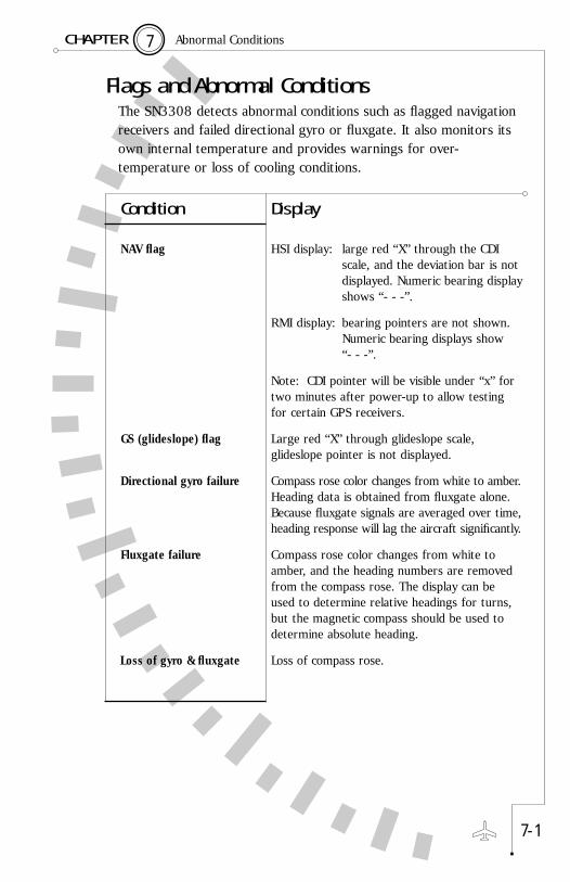
Flags and Abnormal ConditionsThe SN3308 detects abnormal conditions such as flagged navigationreceivers and failed directional gyro or fluxgate. It also monitors itsown internal temperature and provides warnings for over-temperature or loss of cooling conditions.
7 - 1
7 Abnormal ConditionsC H A P T E R
Condition Display
NAV flag HSI display: large red “X” through the CDI scale, and the deviation bar is not displayed. Numeric bearing displayshows “- - -”.
RMI display: bearing pointers are not shown. Numeric bearing displays show“- - -”.
Note: CDI pointer will be visible under “x” fortwo minutes after power-up to allow testingfor certain GPS receivers.
GS (glideslope) flag Large red “X” through glideslope scale,glideslope pointer is not displayed.
Directional gyro failure Compass rose color changes from white to amber.Heading data is obtained from fluxgate alone.Because fluxgate signals are averaged over time,heading response will lag the aircraft significantly.
Fluxgate failure Compass rose color changes from white toamber, and the heading numbers are removedfrom the compass rose. The display can beused to determine relative headings for turns,but the magnetic compass should be used todetermine absolute heading.
Loss of gyro & fluxgate Loss of compass rose.

7 - 2
7 Abnormal ConditionsC H A P T E R
Condition Display
Switching relay failure Redline through nav source such as NAV1 orGPS1. Indicates failure of the externalswitching relay associated with the source andthat the deviation bar on the CDI is invalid.
Fast slave mode Compass heading is redlined. Headinghas not stabilized.
LNAV serial data loss Indicates loss of data communicationfrom the GPS or loran long-range nav receiver.
Invalid GPS data Indicates invalid data is being receivedfrom the Airinc 429 GPS receiver. This isaccompanied by the normal 'X' through the CDIat the bottom of the screen.
Map flag Indicates that map cannot be displayedbecause of loss of LNAV data or a flaggedLNAV.
Stormscope Flag Indicates loss of data communicationfrom the BFG WX-500 Stormscope.
LNAV
123
LNAV
MAP
WX

7 - 3
7 SN3308 On-screen MessagesC H A P T E R
MessagesThe Sandel SN3308 displays different messages to alert the pilot. The messages are initiated by the Pilot, the Built In Self Test (BIST),the Power On Self Test (POST) or by the System. Most of the Pilotinitiated messages are shown on-screen for two seconds and areremoved automatically. Error messages which are considered critical are places on-screen permanently until acknowledged. TheAcknowledgment is done using the ACK soft-key which will appearand flash when such a message appears. It also monitors its owninternal temperature and provides warnings for over-temperature or loss of cooling conditions.
Display Item Source Notes
*OVERTEMP SHUTDOWN* BIST Note 2
+15v OVER VOLTAGE BIST Note 1
+15V UNDER VOLTAGE BIST Note 1
10 MINS TILL OVERTEMP BIST Note 1
-15V OVER VOLTAGE BIST Note 1
-15V UNDER VOLTAGE BIST Note 1
3 DEGREES TO SHUTDOWN BIST Note 2
3v OVER VOLTAGE BIST Note 1
3v UNDER VOLTAGE BIST Note 1
400HZ INVERTER LOSS BIST Loss of main inverter - Note 3
INVERTER FREQ TOO LOW BIST Problem with main inverter - Note 3
INVERTER FREQ TOO HIGH BIST Problem with main inverter - Note 3
5v OVER VOLTAGE BIST Note 1
5v UNDER VOLTAGE BIST Note 1
COOLING FAN FAILURE BIST Note 2

7 - 4
7 SN3308 On-screen MessagesC H A P T E R
Display Item Source Notes
CRC Self-Test Failed POST Program CRC is not the expectedvalue. The “CRC Self Test Failed”message must not appear onpower-up if flight operations arepredicated on the use of theSN3308 Navigational Display.
DEFAULT MEMORIES 1 TO 4 Pilot Appears when map memorylocations have been reset to theirdefault settings by pressing andholding the "CLEAR" softkey whilein the map setup mode.
DEMO MODE: System This message appears when theNOT FOR FLIGHT SN3308 has been placed in demo
mode for use with the Sandeldemonstrator box. In this mode,the SN3308 does not respondnormally to signal inputs. To exitdemo mode, power up theSN3308 while holding the [NAV],[MAP] and [BRG] buttonssimultaneously.
EXT. SWITCH SET TO LORAN Pilot This message appears whenpressing the "NAV" switch on theSN3308 when it is slaved to anexternal loran/NAV switch/annunciator panel. Instead of theSN3308 NAV switch use theexternal loran/NAV switch.

7 - 5
7 SN3308 On-screen MessagesC H A P T E R
Display Item Source Notes
EXTERNAL SWITCH SET TO GPS Pilot This message appears whenpressing the "NAV" switch on theSN3308 when it is slaved to anexternal GPS/NAVswitch/annunciator panel. Insteadof the SN3308 NAV switch use theexternal GPS/NAV switch.
FLUXGATE XYZ LOST BIST Fluxgate XYZ signal voltage toolow or not received.
FLUXGATE EXCITATION LOST BIST Fluxgate excitation has failed.Check the gyro circuit breaker.Note 4
GPS SELECTED EXTERNALLY Pilot This message appears when theSN3308 is slaved to an externalGPS/NAV switch/annunciator paneland it is first placed in GPSposition changing the SN3308display from NAV1 to GPS1.
GYRO XYZ LOST BIST Gyro XYZ (synchro) signal voltage too low or not received.
GYRO INVALID BIST Gyro valid flag asserted. Check thegyro circuit breaker. Note 4
LEG/AUTO (AUTO SLEW) IS ON Pilot Displayed when course knob isturned but course knob setting isover-written by Direct Track fromLong Range Nav Receiver. Auto-slew operation can be disabled byentering the [SHFT]>[NAV] pageand turning auto-slew ON or OFFwith the softkey. If auto-slew isturned off you will have to turn thecourse pointer manually at everywaypoint when flying a flight plan.

7 - 6
7 SN3308 On-screen MessagesC H A P T E R
Display Item Source Notes
LORAN SELECTED EXTERNALLY Pilot This message appears when theSN3308 is slaved to an externalloran/NAV switch/annunciatorpanel and it is first placed in loranposition changing the SN3308display from NAV1 to loran1.
Map Cntl SRC Check FAILED, POST These messages indicate that theMap Data CRC Check FAILED, upload of the map database to Map Cntl Contains Errors the unit was not completed
successfully or the file wascorrupted. Repeat the uploadprocedure. Contact Sandeltechnical support if the messagesreoccur. Note 5
Map Format Conflict POST Indicates a mismatch between theoperating software version andthe map database. Check theSandel website to ensure that youhave the latest versions ofoperating software and databaseand repeat the upload procedure.Note 5
NAV1 TUNED TO ILS Pilot Appears when VHF NAV1 is tunedto an ILS frequency overriding andchanging the SN3308 current NAVselection.
NavData Expires ddmmmyy, BA POST Expiration date of internalJeppesen database. The twoletters following are an internalsoftware code.
NAV2 TUNED TO ILS Pilot Same as above, except pertains toNAV2.
RS232 PORT-0 OVERFLOW System An internal error message whichshould never appear.
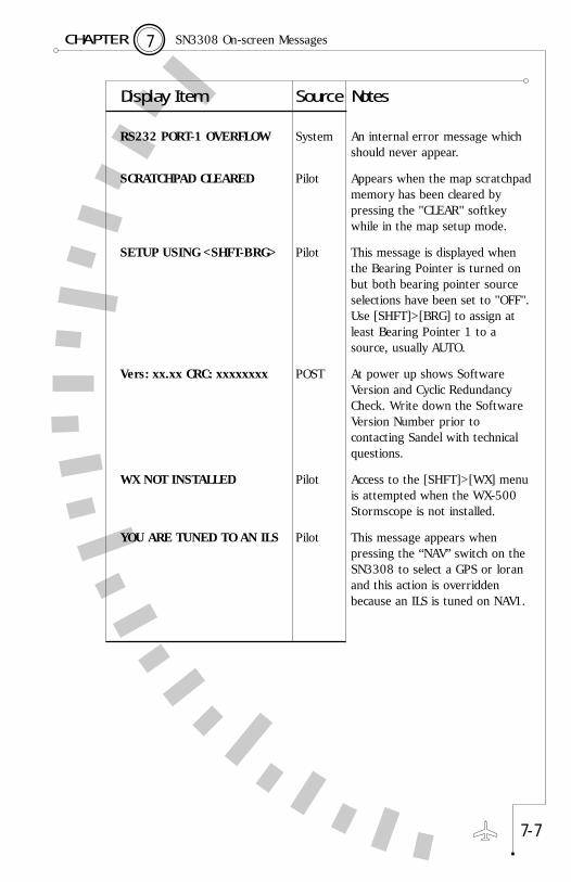
7 - 7
7 SN3308 On-screen MessagesC H A P T E R
Display Item Source Notes
RS232 PORT-1 OVERFLOW System An internal error message whichshould never appear.
SCRATCHPAD CLEARED Pilot Appears when the map scratchpadmemory has been cleared bypressing the "CLEAR" softkeywhile in the map setup mode.
SETUP USING <SHFT-BRG> Pilot This message is displayed whenthe Bearing Pointer is turned onbut both bearing pointer sourceselections have been set to "OFF".Use [SHFT]>[BRG] to assign atleast Bearing Pointer 1 to asource, usually AUTO.
Vers: xx.xx CRC: xxxxxxxx POST At power up shows SoftwareVersion and Cyclic RedundancyCheck. Write down the SoftwareVersion Number prior tocontacting Sandel with technicalquestions.
WX NOT INSTALLED Pilot Access to the [SHFT]>[WX] menuis attempted when the WX-500Stormscope is not installed.
YOU ARE TUNED TO AN ILS Pilot This message appears whenpressing the “NAV” switch on theSN3308 to select a GPS or loranand this action is overriddenbecause an ILS is tuned on NAV1.

7 - 8
7 SN3308 On-screen MessagesC H A P T E R
NOTE 1: BIST is Built In Self Test. This runs continuouslywhile the SN3308 is operating.
NOTE 2: The internal temperature is continuouslymonitored. An overtemp condition will only occurif the cooling fan failure occurs first (the fan stopsturning) or the cooling fan filter is clogged orobstructed. As the temperature rises a warningwill be issued approximately 10 minutes prior toshutdown as a warning. If shutdown occurs theSN3308 will shut off the projection lamp andcontinue operating, and resume normal operationas the internal temperature falls.
NOTE 3: The Inverter failure messages will only appear if a master inverter is installed.
NOTE 4: Gyro Failures will only be annunciated if theinstalled Gyro has a valid flag output. If the"Fluxgate Failed" message appears check the Gyro circuit breaker which is usually the source of Fluxgate power.
NOTE 5: All other functions of the SN3308 continue tooperate normally when the map has failed.

Technical Specifications and Operating Limits
8
CHAPTER

8 Technical Specifications and Operating LimitsC H A P T E R
TSO Compliance
Technical Standard Order (TSO): TSO-C113, Airborne Multipurpose Electronic Displays
Software Certification: RTCA/DO-178B, Level C - Hazardous
Environmental Category: DO-160C: F1CANBMXXXXXXZBABBWA/ZXXXDO-160D: XXXXXXXXXXXXXXXXX(E/F-2)XX
Physical Dimensions
Form Factor: 3ATI (ARINC 408)
Width: 3.165 in. (8.04 cm)
Height: 3.165 in. (8.04 cm)
Length: 10.65 in. (26.24 cm) overall, excludingconnectors & knobs
Weight: 2.9 lbs (1.3 Kg)
Operational Characteristics
Temperature/Altitude: -20˚ C to +70˚ C up to 55,000 ft
Power Inputs: 11 to 33 VDC @ 3.2 Amperes maximum13.75 VDC @ 2.5 Amperes nominal27.5 VDC @ 1.25 Amperes nominal
8 - 1

Installation Information
9
CHAPTER

To Be Completed by Installer
Date of installation:
Installer Company:
Installer Address:
Installer Phone:
Work order #:
Installer:
Nav equipment inputs:
Notes:
9 - 1
9 Installation InformationC H A P T E R

Technology of the SN3308
1
APPENDIX

The Sandel Avionics SN3308 is the first member of an entire familyof products to be based on a new, state-of-the-art display technology.This new type of display, along with a reduced instruction-set (RISC)microprocessor and highly integrated peripheral chips, makes itpossible to acquire and display data from many different cockpitinstruments.
Traditional electronic cockpit displays have been based on eithercathode-ray tube (CRT) or direct-view liquid-crystal display (LCD)technology. One disadvantage of both CRTs and LCDs is that neithercan display an image out to the very edge of the screen. This becomesespecially significant when the outside dimension is constrained toonly three inches across! In a 3 inch cockpit instrument, the amount ofunusable display area on a traditional CRT or LCD can approach 50%.
The SN3308 solves this problem by using a much smaller LCD as theheart of an image projection system. The light beam from aruggedized halogen bulb is first passed through a series of colorsplitters, with each color beam aimed at the corresponding set ofpixels in the LCD. The resulting high-intensity color image is thenprojected through a magnifying lens onto a high-contrast opticalscreen. The final result is a crisp, clear color image which spans thefull height and width of the instrument.
Internally, the physical design of the SN3308 is as unique as thedisplay. Circuit boards are mounted lengthwise, close to the metalcase, to keep clear of the light path between the projection lens andthe screen. The nine pushbuttons are actually at the ends of longconnecting rods which curve back to their switches so as not to cast ashadow on the screen. Even the two knobs actually turn longsegmented shafts connected by universal joints, which provide aprecise mechanical connection while remaining clear of the light path.
The display flexibility of the SN3308 is made possible by the high-speed digital conversion of all analog signals coming into the unit.Heading gyro input, ADF bearing, and even composite VOR signals arereceived, conditioned, and immediately converted into a commondigital format. This allows completely different types of navigationsignals, such as VOR, ADF, and GPS, to be displayed simultaneously.
A 1 - 1
1 Technology of the SN3308A P P E N D I X
Taken together, the image projection system, unique mechanicaldesign, and digital conversion technologies of the SN3308 providenew levels of sophistication to cockpit displays.
A 1 - 2
1 Technology of the SN3308A P P E N D I X

Illustrations
2
APPENDIX

A 2 - 1
Current NAV Source
To/From(Shown for Reference)
Selected Course
DME Distance
Bearing Pointer 1
Current A-BMemory
Bearing Pointer 2
Current Heading
Heading Bug
Bearing Pointer 1 Source& Bearing
Bearing Pointer 2 SourceDistance & Bearing
CDI/Lateral Deviation
Groundspeed
Selected Heading
Course Pointer
Glideslope/Vertical Deviation
ILLUSTRATION 1 – 360 View
360
VIEW

A 2 - 2
Current NAV Source
Bearing Pointer 1
Selected Course
DME Distance
Current A-BMemory
Bearing Pointer 2
Current Heading
Heading Bug
Groundspeed
Bearing Pointer 1 Source & Bearing
Bearing Pointer 2Source, Distance &Bearing
CDI/Lateral Deviation
Selected Heading
Course Pointer
To/From(Shown for Reference)
Glideslope/Vertical Deviation
ILLUSTRATION 2 – ARC View
ARC
VIEW
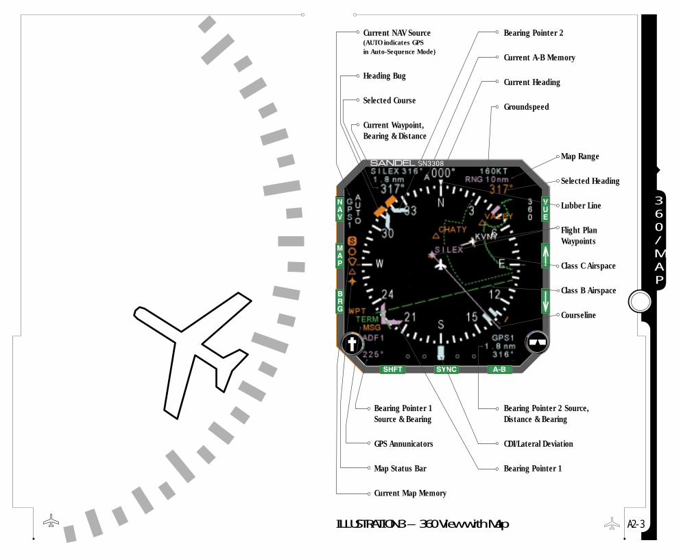
A 2 - 3
360/MAP
ILLUSTRATION 3 – 360 View with Map
Current NAV Source(AUTO indicates GPSin Auto-Sequence Mode)
Heading Bug
Selected Course
Current Waypoint,Bearing & Distance
Bearing Pointer 2
Current A-B Memory
Current Heading
Groundspeed
Bearing Pointer 1Source & Bearing
GPS Annunicators
Map Status Bar
Current Map Memory
Bearing Pointer 2 Source,Distance & Bearing
CDI/Lateral Deviation
Bearing Pointer 1
Map Range
Selected Heading
Lubber Line
Flight PlanWaypoints
Class C Airspace
Class B Airspace
Courseline

A 2 - 4
ARCMOD
Current NAV Source(AUTO Indicates 6PSin Auto-Sequence Mode)
Current Waypoint,Bearing & Distance
Selected Course
Heading Bug
Current A-B Memory
Current Heading
Lubber Line
Bearing Pointer 1
Groundspeed
Bearing Pointer 1 Source & Bearing
Intersections
Map Status Bar
Current Map Memory
CDI/Lateral Deviation
Map Range
Selected Heading
Airport Runways
Class C Airspace
Courseline
ILLUSTRATION 4 – ARC View with Map
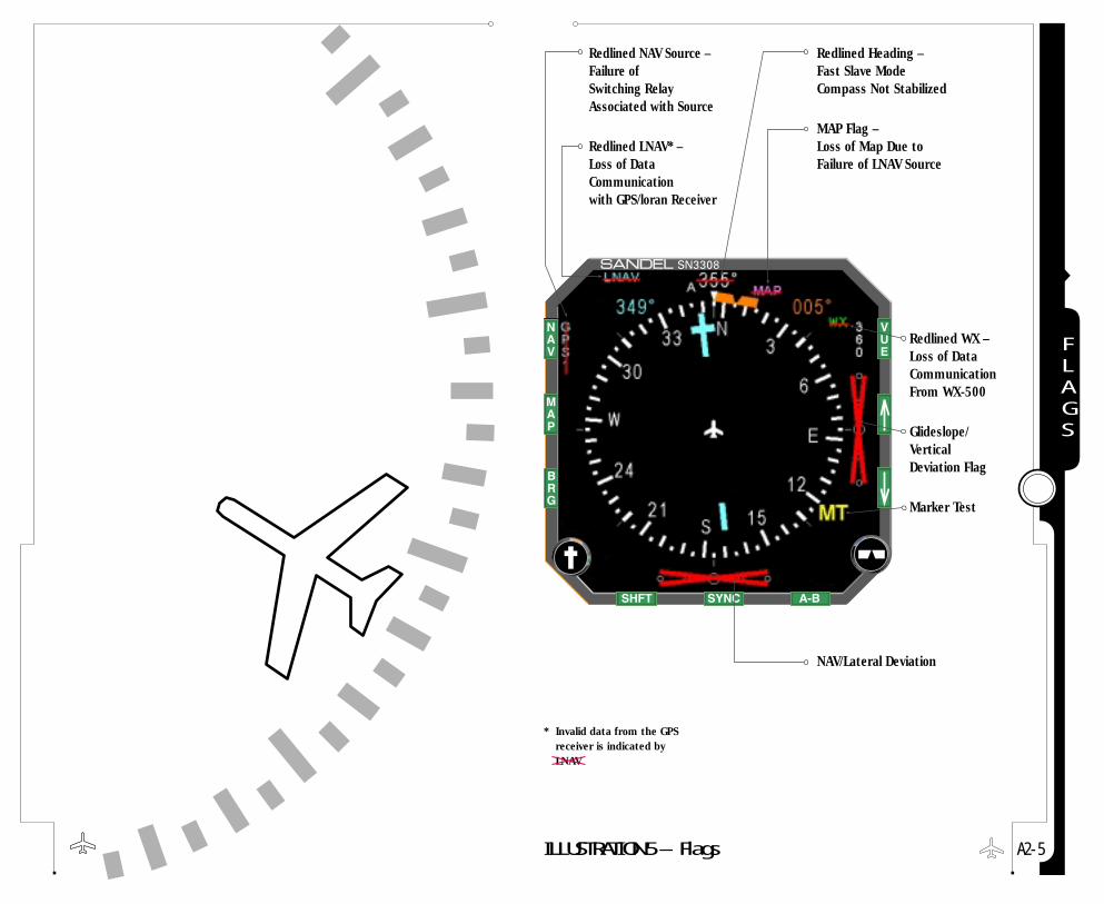
A 2 - 5
FLAGS
ILLUSTRATION 5 – Flags
Redlined NAV Source – Failure ofSwitching RelayAssociated with Source
Redlined LNAV* – Loss of DataCommunicationwith GPS/loran Receiver
Redlined Heading –Fast Slave ModeCompass Not Stabilized
MAP Flag –Loss of Map Due toFailure of LNAV Source
NAV/Lateral Deviation
Redlined WX –Loss of DataCommunicationFrom WX-500
Glideslope/ Vertical Deviation Flag
Marker Test
* Invalid data from the GPS receiver is indicated byLNAV

Limited Parts & Labor Warranty
1
wARRANTY

Sandel Avionics LLC (hereinafter referred to as “Sandel”) provides thefollowing limited warranty. If you should have any questions, pleasecontact the avionics shop that sold you the SN3308 or contact Sandeldirectly.
CONDITIONS OF LIMITED WARRANTYIf during the one (1) year period from the date of original purchaseor installation, your SN3308 is found on authorized inspection tohave a defect in material or workmanship, Sandel or an authorizedrepresentative will repair such defect or replace the defective unitwithout charge for parts or labor. Routine maintenance work and theresults of normal wear are not covered by this warranty except asnoted.
For the next one (1) year Sandel will replace any individual electronicpart, sub-assembly, or finished product judged by Sandel to bedefective, without charge for parts. Parts replaced under this portionof the warranty are warranted for the remainder of the originalproduct warranty or for 90 days (whichever period is longer).
Sandel reserves the right to utilize reconditioned subassemblies aswarranty replacements in the repair of the product. In the eventSandel determines that the unit cannot be repaired, Sandel willreplace the defective unit with either the same model product or onethat is reasonably equivalent. At Sandel’s discretion, replacement unitsor repaired units may include software or hardware updates andrevisions that alter some characteristics of the product.
Should warranty service be required, the warranty period will beextended by the number of days that elapse between the date adefect is reported and the date that the repaired unit is returned.Sandel assumes no responsibility for payment of any repair servicesperformed by third parties including removal of the unit from theaircraft, inspection, packaging, handling, or installation unless suchservices are authorized in advance and in writing by Sandel.
Sandel reserves the right to make changes, upgrades, andimprovements to its products without incurring any obligation toinstall such changes, upgrades, and improvements in previouslymanufactured products.
W - 1
1 Limited Parts & Labor WarrantyWARRANTY

If during the warranty period, title to the aircraft in which theproduct is installed is transferred the remainder of the warranty maybe transferred to the new owner by notifying Sandel in writing of thetransaction. Such notification must include complete addressinformation for the original owner and the new owner as well as theN number and serial number of the aircraft and the serial number ofthe Sandel product.
Please contact Sandel directly if you have any questions regarding theSandel limited warranty. This limited warranty is applicable only inthe fifty states of the USA and the District of Columbia. It is notapplicable in the possessions or territories of the USA or in any othercountry. This limited warranty is the only warranty which Sandelmakes with respect to your SN3308. Sandel disclaims all otherwarranties relating to the product including warranties ofmerchantability and fitness for a particular use.
In any event, Sandel shall not be liable for any incidental orconsequential damages. Some states do not allow the exclusion orlimitation of incidental or consequential damages and some states donot allow limitations on how long an implied warranty may last;therefore, the above limitations or exclusions may not apply to you.This warranty gives you specific legal rights. You may also have otherrights that vary from state to state. In the event any of theprovisions of this warranty are found by statute or by applicableadministrative or judicial entity to be unenforceable, the remainingprovisions shall remain in force.
OWNERS RESPONSIBILITIESPlease read the Pilot’s Guide of your SN3308 and the equipment towhich it is connected. The information provided in your Pilot’s Guidecovers operation, safety precautions and routine maintenance. Thiswarranty does NOT cover expenses incurred due to a lack ofunderstanding of the functioning of the product when it is operatingas designed.
In order for Sandel to provide proper warranty service, you may berequired to:
W - 2
1 Limited Parts & Labor WarrantyWARRANTY

■ Supply proof of purchase documents.■ Permit Sandel or an authorized representative to provide
the applicable warranty service during normal business hours.■ Retain and provide to Sandel (upon request) any
documentation of the installation of the product in your aircraft.
■ Provide Sandel with all pertinent information regarding the symptoms, failure, or defect initiating the request for warranty service.
EXCLUSIONSThis warranty does not cover the following:
■ Projection lamp.■ Failures that are the result of improper installation,
maintenance, or repair.■ Failures that result from neglect, abnormal strain,
modification, accidental damage, theft, vandalism, or exposure to extremes in temperature or relative humidity.
■ Products whose trademark, name, or identification numbershave been altered or removed.
■ Radio frequency interference generated by equipment operated in violation of applicable FCC rules.
■ Equipment purchased “As New” from a dealer or distributornot authorized by Sandel.
All product or material returned to Sandel must be properly packedand labeled with a Returned Material Authorization (RMA) number.Should proper packing materials not be available, Sandel will providean approved shipping container on request.
W - 3
1 Limited Parts & Labor WarrantyWARRANTY


![[BFG] Ramilies](https://static.fdocuments.in/doc/165x107/577c79091a28abe0549132d0/bfg-ramilies.jpg)


![BFG [Codex] Adeptus Mechanicus](https://static.fdocuments.in/doc/165x107/563db981550346aa9a9df875/bfg-codex-adeptus-mechanicus.jpg)