![SMV [McMillan 93]](https://static.fdocuments.in/doc/165x107/5681572a550346895dc4c47a/smv-mcmillan-93.jpg)
SMV-001 Thermostatic Shower Mixer Valve · The SMV-001 Mixer is a thermostatic shower valve with...
20
3 8 READ ALL INSTRUCTIONS CAREFULLY BEFORE INSTALLATION. LEAVE THIS BOOKLET WITH THE END USER FOR FUTURE REFERENCE AND SERVICING. SMV-001 Thermostatic Shower Mixer Valve Installation Instructions & Adjustment Settings
Transcript of SMV-001 Thermostatic Shower Mixer Valve · The SMV-001 Mixer is a thermostatic shower valve with...
38
READ ALL INSTRUCTIONS CAREFULLY BEFOREINSTALLATION. LEAVE THIS BOOKLET WITH THE ENDUSER FOR FUTURE REFERENCE AND SERVICING.
TM
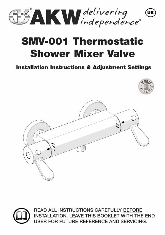
SMV-001 ThermostaticShower Mixer Valve
Installation Instructions & Adjustment Settings
INTRODUCTION
The SMV-001 Mixer is a thermostatic shower valve with independent control levers fortemperature and flow.The SMV-001 responds rapidly to changes in temperature and pressure in order tomaintain a safe, steady showering temperature.The SMV-001 has been designed for use in UK healthcare premises as a Type 3 mixingvalve under the TMV3 scheme.
For TMV3 installations the maximum temperature and maximum override temperaturecan be preset to 41°C to ensure safe showering. For non TMV3 installations the maximum temperature and maximum override temperature can be set to the desired temperature of the user.This override button allows the user to exceed the normal preset maximum temperature.
The maximum normal flow rate and maximum override flow rate button can be adjustedto suit the desired flow rate of the user or the override button can be disabled, safelylimiting the amount of water used.
The SMV-001 also includes check valves and filters.
The THERMOSTATIC MIXING VALVE (SMV-001) is designed to comply with the N.H.SEstate Model Engineering Specification-D08.
The SMV-001 Mixer valve is approved for use in the following designations.The following abbreviated designation codes are used throughout this manual.
HP High pressure LP Low pressure S ShowerE Economic
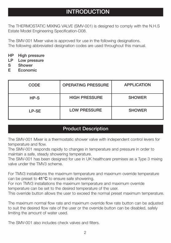
Product Description
CODE OPERATING PRESSURE APPLICATION
HIGH PRESSURE
LOW PRESSURE
HP-S
LP-SE
SHOWER
SHOWER
2
Product SpecificationsImportant Points:1. The installation, commissioning and maintenance of this product must be carried out
in accordance with instructions given in this manual, and must be conducted by designated, qualified and competent personnel.
2. Installation must comply with all local/National Water Supply Authority Regulations/Bye-laws and Building and Plumbing Regulations.
3. Warning: continued use of this product in conditions outside the limits listed in this section can severely affect the performance and reduce the effective service life and can present potential risk to users.
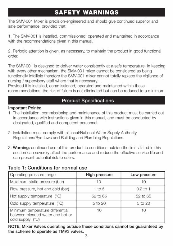
Table 1: Conditions for normal use
NOTE: Mixer Valves operating outside these conditions cannot be guaranteed bythe scheme to operate as TMV3 valves.
3
Operating pressure range High pressure Low pressure
Maximum static pressure (bar) 10 10
Flow pressure, hot and cold (bar) 1 to 5 0.2 to 1
Hot supply temperature (°C) 52 to 65 52 to 65
Cold supply temperature (°C) 5 to 20 5 to 20
Minimum temperature differential between blended water and hot or cold supply (°C)
10 10
The SMV-001 Mixer is precision-engineered and should give continued superior andsafe performance, provided that:
1. The SMV-001 is installed, commissioned, operated and maintained in accordancewith the recommendations given in this manual.
2. Periodic attention is given, as necessary, to maintain the product in good functionalorder.
The SMV-001 is designed to deliver water consistently at a safe temperature. In keeping with every other mechanism, the SMV-001 mixer cannot be considered as being functionally infallible therefore the SMV-001 mixer cannot totally replace the vigilance ofnursing / supervisory staff where that is necessary.Provided it is installed, commissioned, operated and maintained within these recommendations, the risk of failure is not eliminated but can be reduced to a minimum.
SAFETY WARNINGS
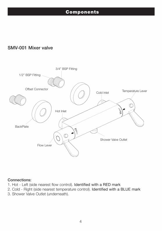
Components
Connections: 1. Hot - Left (side nearest flow control). Identified with a RED mark2. Cold - Right (side nearest temperature control). Identified with a BLUE mark3. Shower Valve Outlet (underneath).
4
38
Offset Connector
1/2” BSP Fitting
3/4” BSP Fitting
Hot Inlet
Cold Inlet
BackPlate
Flow Lever
Temperature Lever
Shower Valve Outlet
SMV-001 Mixer valve
Installation
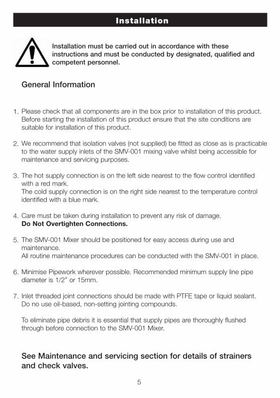
Installation must be carried out in accordance with these instructions and must be conducted by designated, qualified andcompetent personnel.
5
General Information
Please check that all components are in the box prior to installation of this product.Before starting the installation of this product ensure that the site conditions are suitable for installation of this product.
We recommend that isolation valves (not supplied) be fitted as close as is practicableto the water supply inlets of the SMV-001 mixing valve whilst being accessible formaintenance and servicing purposes.
The hot supply connection is on the left side nearest to the flow control identified with a red mark.The cold supply connection is on the right side nearest to the temperature control identified with a blue mark.
Care must be taken during installation to prevent any risk of damage. Do Not Overtighten Connections.
The SMV-001 Mixer should be positioned for easy access during use and maintenance. All routine maintenance procedures can be conducted with the SMV-001 in place.
Minimise Pipework wherever possible. Recommended minimum supply line pipe diameter is 1/2” or 15mm.
Inlet threaded joint connections should be made with PTFE tape or liquid sealant. Do no use oil-based, non-setting jointing compounds.
To eliminate pipe debris it is essential that supply pipes are thoroughly flushed through before connection to the SMV-001 Mixer.
See Maintenance and servicing section for details of strainersand check valves.
1.
2.
3.
4.
5.
6.
7.
6
Operation
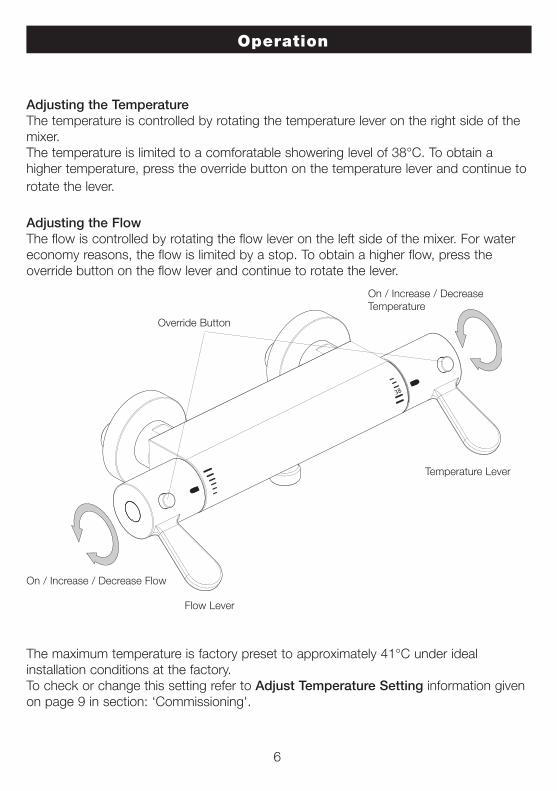
Adjusting the TemperatureThe temperature is controlled by rotating the temperature lever on the right side of themixer.The temperature is limited to a comforatable showering level of 38°C. To obtain ahigher temperature, press the override button on the temperature lever and continue torotate the lever.
Adjusting the FlowThe flow is controlled by rotating the flow lever on the left side of the mixer. For watereconomy reasons, the flow is limited by a stop. To obtain a higher flow, press the override button on the flow lever and continue to rotate the lever.
The maximum temperature is factory preset to approximately 41°C under ideal installation conditions at the factory. To check or change this setting refer to Adjust Temperature Setting information givenon page 9 in section: ‘Commissioning'.
38
Override Button
Flow Lever
Temperature Lever
On / Increase / Decrease Flow
On / Increase / DecreaseTemperature
Commissioning
Method for Commissioning Thermostatic Mixing Valves
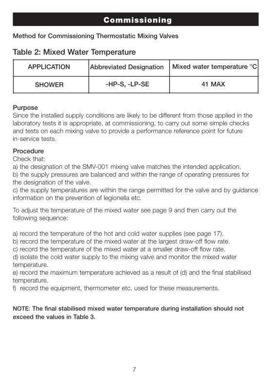
Table 2: Mixed Water Temperature
PurposeSince the installed supply conditions are likely to be different from those applied in thelaboratory tests it is appropriate, at commissioning, to carry out some simple checksand tests on each mixing valve to provide a performance reference point for futurein-service tests.
ProcedureCheck that:a) the designation of the SMV-001 mixing valve matches the intended application.b) the supply pressures are balanced and within the range of operating pressures forthe designation of the valve.c) the supply temperatures are within the range permitted for the valve and by guidanceinformation on the prevention of legionella etc.
To adjust the temperature of the mixed water see page 9 and then carry out the following sequence:
a) record the temperature of the hot and cold water supplies (see page 17).b) record the temperature of the mixed water at the largest draw-off flow rate.c) record the temperature of the mixed water at a smaller draw-off flow rate.d) isolate the cold water supply to the mixing valve and monitor the mixed water temperature.e) record the maximum temperature achieved as a result of (d) and the final stabilisedtemperature.f) record the equipment, thermometer etc. used for these measurements.
NOTE: The final stabilised mixed water temperature during installation should notexceed the values in Table 3.
7
APPLICATION Abbreviated Designation Mixed water temperature °C
-HP-S, -LP-SESHOWER 41 MAX
Commissioning
Commissioning must be carried out in accordance with theseinstructions and must be conducted by designated, qualified andcompetent personnel.
Maximum Temperature
The maximum blend temperature obtainable by the user should be limited to preventaccidental selection of a temperature that is too hot.The SMV-001 Mixer valve is fully performance tested and the maximum temperature ispreset to 41°C under ideal installation conditions at the factory. Site conditions andpersonal preference may dictate that the maximum temperature has to be reset following installation.
Maximum Temperature Setting
Make sure that an adequate supply of hot water is available at the hot inlet of the SMV-001 Mixer. The minimum temperature of the hot water must be at least 10°Cabove the desired blend. However, during resetting this should be close to the typicalstorage maximum to offset the possibility of any blend shift due to fluctuating supplytemperatures. Make sure that both inlet isolating valves are fully open.Temperatures should always be measured using a thermometer with proven accuracy.
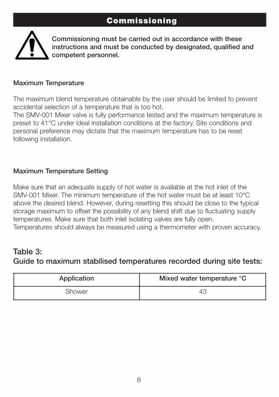
Table 3: Guide to maximum stabilised temperatures recorded during site tests:
8
Application Mixed water temperature °C
Shower 43
9
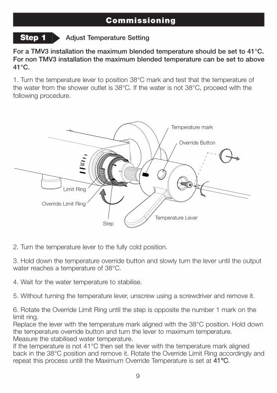
For a TMV3 installation the maximum blended temperature should be set to 41°C. For non TMV3 installation the maximum blended temperature can be set to above41°C.
1. Turn the temperature lever to position 38°C mark and test that the temperature ofthe water from the shower outlet is 38°C. If the water is not 38°C, proceed with the following procedure.
2. Turn the temperature lever to the fully cold position.
3. Hold down the temperature override button and slowly turn the lever until the outputwater reaches a temperature of 38°C.
4. Wait for the water temperature to stabilise.
5. Without turning the temperature lever, unscrew using a screwdriver and remove it.
6. Rotate the Override Limit Ring until the step is opposite the number 1 mark on thelimit ring. Replace the lever with the temperature mark aligned with the 38°C position. Hold downthe temperature override button and turn the lever to maximum temperature. Measure the stabilised water temperature. If the temperature is not 41°C then set the lever with the temperature mark alignedback in the 38°C position and remove it. Rotate the Override Limit Ring accordingly andrepeat this process untill the Maximum Override Temperature is set at 4411°°CC.
Commissioning
38
38
23
5
7
14
6
23
5
7
14
6
Limit Ring
Temperature Lever
Override Button
Override Limit Ring
Step 1 Adjust Temperature Setting
Temperature mark
Step
Commissioning
10
Step 2 Adjust Flow Rate Setting
If the preset flow rate is not appropriate, you may choose to adjust it. For example, you may choose to lower the flow rate to save water.Both Normal and Maximum Override flow rate positions may be adjusted.
1. Turn the Flow Lever to the fully off position. Unscrew the flow lever and remove without turning it. Replace the Flow Lever at the desired off position.
2. Hold down the Override Button and slowly turn the Lever until the output water reaches the desired Normal flow rate position. Record the flow mark position on theshower mixer.
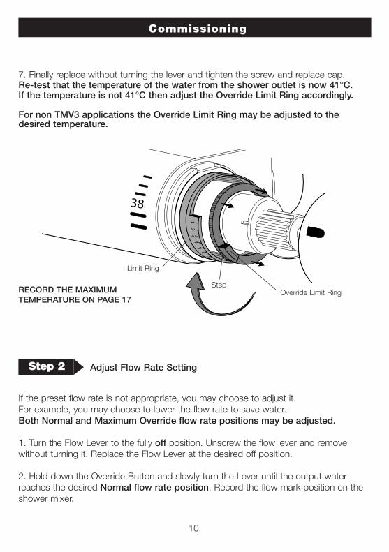
7. Finally replace without turning the lever and tighten the screw and replace cap.Re-test that the temperature of the water from the shower outlet is now 41°C.If the temperature is not 41°C then adjust the Override Limit Ring accordingly.
For non TMV3 applications the Override Limit Ring may be adjusted to thedesired temperature.
38
38 2
35
7
14
6
23
5
7
14
6
Limit Ring
Override Limit RingRECORD THE MAXIMUM TEMPERATURE ON PAGE 17
Step
Flow Lever
Override Button
Limit Ring
Override Limit Ring
Flow mark
Commissioning
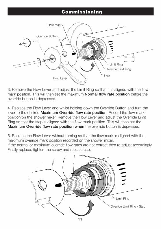
3. Remove the Flow Lever and adjust the Limit Ring so that it is aligned with the flowmark position. This will then set the maximum Normal flow rate position before theoverride button is depressed.
4. Replace the Flow Lever and whilst holding down the Override Button and turn thelever to the desired Maximum Override flow rate position. Record the flow markposition on the shower mixer. Remove the Flow Lever and adjust the Override LimitRing so that the step is aligned with the flow mark position. This will then set theMaximum Override flow rate position when the override button is depressed.
5. Replace the Flow Lever without turning so that the flow mark is aligned with themaximum override mark position recorded on the shower mixer. If the normal or maximum override flow rates are not correct then re-adjust accordingly.Finally replace, tighten the screw and replace cap.
Limit Ring
Override Limit Ring - Step
11
Step
Maintenance and Servicing
12
Maintaining the Check Valves & Strainers:
The Check Valves are located inside the Inlet Connector of the Shower Valve to preventbackflow, the Strainers are installed inside of the Inlet Connectors to stop the debrisfrom entering the Shower Valve.
Caution! Make sure that the Check Valves are replaced correctly, otherwise cross flowmay occur.
1. Turn off the hot and cold water supplies.
2. Remove the Shower Valve from the wall by unscrewing the Inlet Connector with a spanner. Use a cloth to protect the finish.
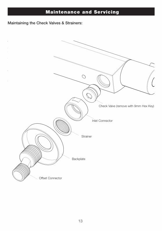
3. Unscrew the Inlet Connector from the Shower Valve with a 9mm hexagon key in a clockwise direction (opposite to a normal screw direction).Note! Keep the washer in the Inlet Connector.
4. Push the Check Valve out of the Inlet Connector.
5. Rinse the Check Valve and the strainer and clean out any debris.
6. Replace the Check Valve in the Inlet Connecter, ensuring that the check valve is fitted with the flow arrow pointing towards the Shower Valve.
7. Refit the Inlet Connector to the Shower Valve and tighten with a 9mm hexagon key in an anti-clockwise direction.
8. Replace the Shower Valve on the wall and tighten the Iinlet Connectors with a spanner.
Use a cloth to protect the finish.
9. Turn on the hot and cold water supplies and check for any leaks.
Maintenance and Servicing
Maintaining the Check Valves & Strainers:
13
Check Valve (remove with 9mm Hex Key)
Inlet Connector
Offset Connector
Backplate
Strainer
14
IN-SERVICE TESTING
The purpose of in-service testing is to regularly monitor the thermal performance of theSMV-001 Mixer valve. Deterioration in performance can indicate the need for servicework to be carried out on the system.If the authority concerned does not have a planned test and maintenance schedulethen the suggestions below should form the basis of a new system.
At intervals of 6-8 weeks and 12-15 weeks after commissioning:-1. Check supply parameters are still within the expected values if not check system forfaults.2. Carry out commissioning procedures using the same test equipment, if the mixedwater temperature has changed a significant amount (by more than 1°C) check toensure in line filters are clean, that the check valves are working and all isolation valvesare fully open. If no fault can be found check and record the mixed water temperatures and re-adjustmixed water temperature to the values in table 3, complete the commissioning procedure. If the mixed water temperature exceeds the values of the maximum recorded temperature by more than 2°C the need for service work is indicated.
Depending on the results of these two tests the following should be adopteda) If a small change (e.g. 1°C to 2°C) occurs in one of these tests or there is no significant change (e.g. 1°C maximum) then the next in service test should be 24 to 28weeks after commissioning.b) If small changes occur in both test or a larger change occurs in one test (exceeding 2°C) then the next in service test should be carried out 18 to 21 weeks aftercommissioning.
These results can then be used to set a service interval which tests have shown can beused with no more than a small change in mixed water temperature. This method ofdetermining service intervals is used to take into account various in–service conditions(i.e. water condition) that the valve may experience.
Cleaning and Care
Clean using warm, soapy water only. Do not use scourers or abrasive cleaners which may affect the surface finish.Never use corrosive acidic or alkaline cleaning materials on fittings or surfaces. Always flush cleaning materials away with copious amounts of water and wipe down.
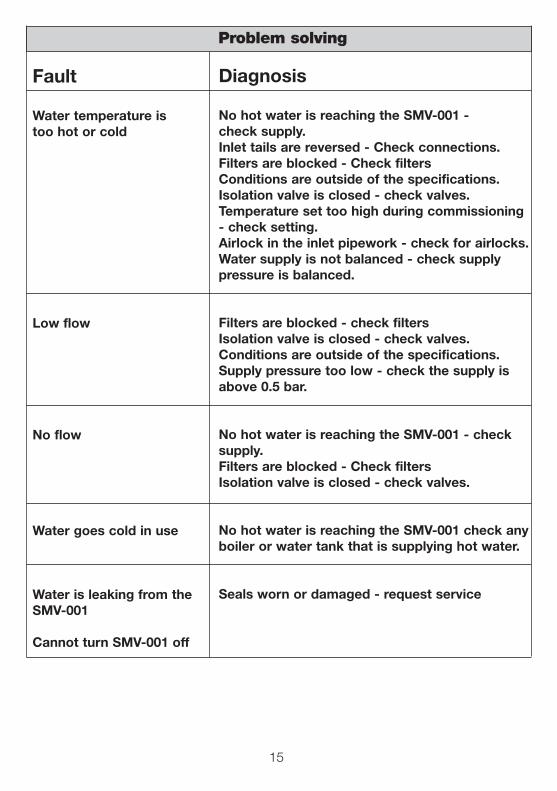
Problem solving
Fault
Water temperature is too hot or cold
Low flow
No flow
Water goes cold in use
Water is leaking from the SMV-001
Cannot turn SMV-001 off
Diagnosis
No hot water is reaching the SMV-001 - check supply.Inlet tails are reversed - Check connections.Filters are blocked - Check filtersConditions are outside of the specifications.Isolation valve is closed - check valves.Temperature set too high during commissioning- check setting.Airlock in the inlet pipework - check for airlocks.Water supply is not balanced - check supplypressure is balanced.
Filters are blocked - check filtersIsolation valve is closed - check valves.Conditions are outside of the specifications.Supply pressure too low - check the supply isabove 0.5 bar.
No hot water is reaching the SMV-001 - check supply.Filters are blocked - Check filtersIsolation valve is closed - check valves.
No hot water is reaching the SMV-001 check anyboiler or water tank that is supplying hot water.
Seals worn or damaged - request service
15
16
Model/Part Number
SMV-001 Serial Number (SN)
Batch number (BN)
INSTALLED ON
INSTALLED BY
ADDRESS
CONTACT
To be completed by Installer
Please complete the registration card within 30 days and return to us inthe prepaid envelope for your Free Warranty to start.
Product Identification label can be found on the outer packaging.
TM
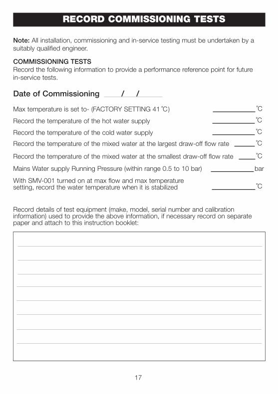
Note: All installation, commissioning and in-service testing must be undertaken by asuitably qualified engineer.
COMMISSIONING TESTSRecord the following information to provide a performance reference point for futurein-service tests.
Date of Commissioning / /
Record the temperature of the hot water supply
Mains Water supply Running Pressure (within range 0.5 to 10 bar) bar
˚C
With SMV-001 turned on at max flow and max temperaturesetting, record the water temperature when it is stabilized ˚C
Record details of test equipment (make, model, serial number and calibration information) used to provide the above information, if necessary record on separatepaper and attach to this instruction booklet:
RECORD COMMISSIONING TESTS
Record the temperature of the mixed water at the largest draw-off flow rate ˚C
Record the temperature of the mixed water at the smallest draw-off flow rate ˚C
Max temperature is set to- (FACTORY SETTING 41 ) ˚C
17
Record the temperature of the cold water supply ˚C
˚C
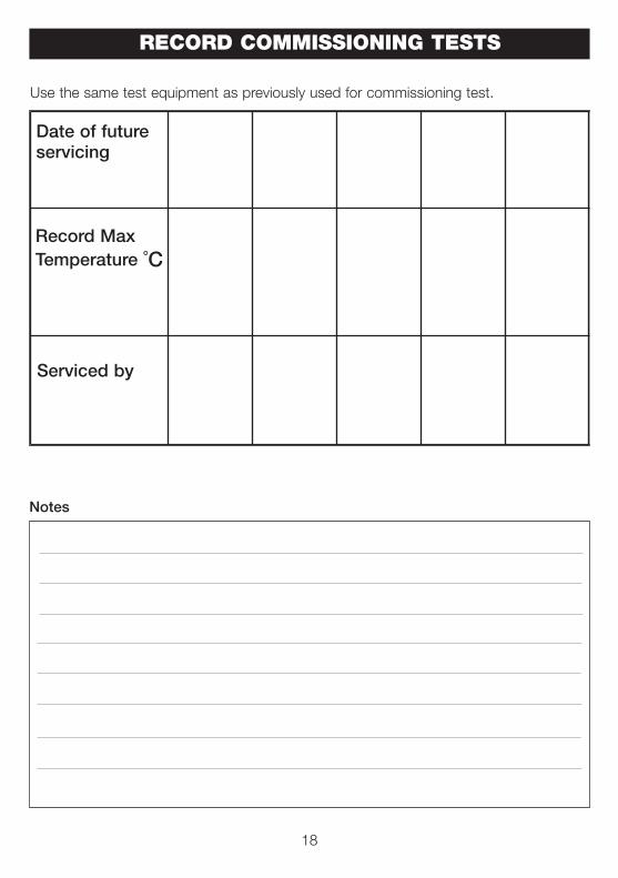
Serviced by
Record MaxTemperature ˚C
Date of futureservicing
Use the same test equipment as previously used for commissioning test.
RECORD COMMISSIONING TESTS
Notes
18
WARRANTY
As part of the on-going improvement programme, AKW MediCare would appreciateany feedback on these instructions.If you have any comments please contact us on Tel:+44 (0) 01905 823235
This warranty is in addition to your statutory and other legal rights.
To validate and start the warranty, you must return your completed registration card.
AKW Medi-Care Ltd warranty Covers your SMV-001 mixer valve against any defects inmanufacturing or materials for 2 years from the date of installation. Within this periodwe will resolve defects free of charge by repairing or replacing as we may choose. Tobe free of charge work must be only undertaken by AKW or our approved agents in theUK or the Republic of Ireland and with prior agreement.
Any action taken under this warranty does not extend the stated 2-year expiry date.
NOT COVERED BY THIS WARRANTYDamage or defects arising from incorrect installation, improper use, lack of maintenanceincluding the build-up of limescale or any unauthorised modifications.
Actions taken to dismantle, repair or modify beyond that shown in this installationguide, by persons who are not AKW Medi-Care Ltd authorised service staff or agents.
Damage resulting from water freezing.
BEFORE USING YOUR SMV-001 MIXING VALVEPlease take time to read and understand the operating and safety instructions detailedin this manual.
WHAT TO DO IF SOMETHING GOES WRONGIf your shower does not work correctly first follow the Problem solving chart on page12, then contact your installer.
Should this not resolve your problem, contact AKW Customer Services who will providefurther advice and if necessary arrange for a service engineer to visit or discuss ourcomprehensive after-sales service. As part of a quality and training program calls maybe monitored or recorded.
None of the forgoing affects your statutory rights.
19
© 2010 AKW Medi-Care Limited 08-013-003-02
AKW Medi-Care Limited, Pointon Way, Hampton Lovett, Droitwich Spa, WR9 0LRTel.+44 (0) 1905 823298 - Fax. +44 (0) 1905 823297 - www.akw-medicare.co.uk
For further details on this and other AKW products please contact your distributor- see details on outer packaging
The measurements throughout these installation and user care instructions have been converted from metric to its equivalentin imperial, therefore all dimensions are approximate and subject to manufacturing tolerances.
This information is furnished upon the condition that the person receiving it shall make his/her own tests to determine the suitability thereof for his/her particular purpose.
Failure to install this AKW MediCare product in accordance with supplied instructions or the makingof any unauthorised modifications, will invalidate any warranty and will affect product safety.