SMS Gateway and Communication Interfaces for a...
94
UNIVERSIDADE DE LISBOA Faculdade de Ciências Departamento de Informática SMS Gateway and Communication Interfaces for a Callcenter David Alberto Neto Pacheco dos Reis PROJECTO Projecto orientado pelo Prof. Dr João Pedro Neto e co-orientado por João Paulo Pereira Mestrado em Engenharia Informática 2008
Transcript of SMS Gateway and Communication Interfaces for a...

UNIVERSIDADE DE LISBOA
Faculdade de Ciências
Departamento de Informática
SMS Gateway and Communication Interfaces for a
Callcenter
David Alberto Neto Pacheco dos Reis
PROJECTO
Projecto orientado pelo Prof. Dr João Pedro Neto
e co-orientado por João Paulo Pereira
Mestrado em Engenharia Informática
2008
Final Report: SMS Gateway and Communication Interfaces for a Callcenter
David Alberto Neto Pacheco dos Reis 2/94
Declaration
David Alberto Neto Pacheco dos Reis, student nº 31601 of Faculdade de Ciências Universidade
de Lisboa, declares to give the copy rights of its Report of Projecto em Engenharia Informática,
named “SMS Gateway and Communication Interfaces for a Callcenter”, accomplished during
the year 2007/2008 to Faculdade de Ciências Universidade de Lisboa for effects of archive and
consultation on its libraries and publication on electronic format on the Internet.
David Alberto Neto Pacheco dos Reis aluno nº31601 da Faculdade de Ciências Universidade de
Lisboa, declara ceder os seus direitos de cópia sobre o seu Relatório de Projecto em
Engenharia Informática, intitulado “SMS Gateway and Communication Interfaces for a
Callcenter”, realizado no ano lectivo de 2007/2008 á Faculdade de Ciências Universidade de
Lisboa para o efeito de arquivo e consulta nas suas bibliotecas e publicação do mesmo em
formato electrónico na Internet.
Lisboa, 20 de Junho de 2008
_ _

Final Report: SMS Gateway and Communication Interfaces for a Callcenter
David Alberto Neto Pacheco dos Reis 3/94
Final Report: SMS Gateway and Communication Interfaces for a Callcenter
David Alberto Neto Pacheco dos Reis 4/94
Abstract
After the boom of the Internet we are assisting to a new boom on the mobile services
offerings. TIM w.e. is a young Portuguese company that has taken advantage from this new
area and on the few years of its existence grown into a multinational company.
The work here presented shows one of the core tasks developed at TIM w.e.: the integration
with mobile carriers and brokers. On this work will be presented the several steps needed to
integrate new carriers into the existing platform and all the process involved on the task.
The particular case presents the integration of a Broker from Brazil with TIM w.e. platform.
This Broker aggregates four mobile carrier connections (Claro, TIM, BRT and OI).
The development of this project is divided on two main phases: the SMS Gateway that allows
the exchange of messages between the platforms and the Callcenter communication
interfaces that are used by the broker and mobile carriers to manage their users on TIM w.e.
database.
This project was implemented into a complex platform and network structure composed by
clustered databases, replicated application servers, firewalls and load balancers. This project is
now on production and is transacting millions of SMS per day.
This report also gives a brief description of the company, internal structure, workflow and the
products it develops internally.

Final Report: SMS Gateway and Communication Interfaces for a Callcenter
David Alberto Neto Pacheco dos Reis 5/94
Resumo
Após a explosão da internet estamos actualmente a assistir á explosão dos serviços para
telemóveis. A TIM w.e. é uma jovem empresa portuguesa que tirou vantagem desta área e nos
poucos anos da sua existência consegui transformar-se numa empresa multinacional.
O trabalho aqui apresentado descreve uma das tarefas mais importantes efectuadas na TIM
w.e., a integração de novos operadores na plataforma e todo o processo envolvido nesta
tarefa.
Este caso particular apresenta a integração de um broker do Brasil com a plataforma da TIM
w.e.. Este broker agrega ligações a quatro operadores moveis (Claro, TIM, BRT e OI).
O desenvolvimento deste projecto está dividido em duas fases principais: O Gateway SMS que
permite a troca de mensagens entre as plataformas, e as interfaces de comunicação para o
Callcenter que são utilizadas pelo broker e pelos operadores moveis para gerir os seus
utilizadores na base de dados da TIM w.e.
Este projecto foi implementado numa plataforma complexa com um estrutura composta por
várias base de dados, servidores aplicacionais replicados, anteparas e controladores de carga.
Este projecto já se encontra em produção e está a transaccionar milhões de mensagens por
dia.
Este relatório inclui também uma breve descrição da empresa, estrutura interna, fluxo de
trabalho e outros produtos desenvolvidos internamente.
Final Report: SMS Gateway and Communication Interfaces for a Callcenter
David Alberto Neto Pacheco dos Reis 6/94
Greetings
I want to thank my guide professor João Pedro Neto and my supervisor João Paulo Pereira for
all their availability and help provided during the development of this project.
A big thank to all my work colleagues that had the patience to answer my doubts and were
always available to help and teach when I needed.
I must also thank my family, university colleagues and friends for their support and
encouragement on the good and bad moments.
To finish I want to give a special thanks to my parents for all their effort and faith during the
last five years and for giving me the opportunity to take this degree.

Final Report: SMS Gateway and Communication Interfaces for a Callcenter
David Alberto Neto Pacheco dos Reis 7/94
Index
Figures Index ..................................................................................................................... 10
Tables Index ...................................................................................................................... 12
1 - Introduction ................................................................................................................. 13
1.1 - TIM w.e............................................................................................................................ 13
1.1.1 - Evolution .................................................................................................................. 14
1.1.2 - Internal Structure ..................................................................................................... 15
1.2 - Project Description .......................................................................................................... 16
1.3 - Report Structure.............................................................................................................. 17
2 - IT Department .............................................................................................................. 18
2.1 - IT Structure ...................................................................................................................... 18
2.2 - Brazil Team ...................................................................................................................... 18
2.3 - Development Tools ......................................................................................................... 19
2.4 - Development Environment ............................................................................................. 19
2.4.1 - Testing methodology of the New Services ............................................................... 20
2.5 - Workflow Management .................................................................................................. 23
3 - Initial Work ................................................................................................................... 25
3.1 - Webspots Project ............................................................................................................ 25
3.2 - New Countries, Services and Clubs integration .............................................................. 25
3.3 - Wap Sites ......................................................................................................................... 26
3.4 - Xconns (Carrier Connections: Billing;SMS Gateway)....................................................... 27
3.5 - Initial Work Calendar ...................................................................................................... 28
4 – Project Objectives and Methodologies .......................................................................... 29
4.1 - Objectives ........................................................................................................................ 29
4.2 - Methodology Approach .................................................................................................. 29
4.2.1 - Methodology ............................................................................................................ 29
4.2.2 - Waterfall Model ....................................................................................................... 29
4.2.3 - Requisites and Analysis Specification ...................................................................... 30
4.2.4 - Project Design .......................................................................................................... 30
4.2.5 - Implementation........................................................................................................ 30
4.2.6 - Testing ...................................................................................................................... 30
4.2.7 - Maintenance ............................................................................................................ 30
4.3 - Project Calendar .............................................................................................................. 31
Final Report: SMS Gateway and Communication Interfaces for a Callcenter
David Alberto Neto Pacheco dos Reis 8/94
5 - The Project ................................................................................................................... 32
5.1 - Requisites Analysis .......................................................................................................... 32
5.1.1 - Broker Requisites ..................................................................................................... 32
5.1.2 - TIM w.e. Platform Requisites ................................................................................... 32
5.1.3 - Interfaces Definition ................................................................................................. 33
5.1.4 - Presumed Implementation Environment ................................................................ 34
5.2 - Use Cases ........................................................................................................................ 36
5.2.1 - The Components ...................................................................................................... 36
5.2.2 - Use Cases Diagrams ................................................................................................. 37
5.2.3 - Use Cases Descriptions............................................................................................. 39
5.3 - Activity Diagrams ............................................................................................................ 47
5.3.1 - Broker Communication Interfaces Activity Diagrams .............................................. 47
5.3.2 - Broker Callcenter Interfaces Activity Diagrams ....................................................... 55
5.4 - Class Diagrams ................................................................................................................ 62
5.4.1 - Broker Communication Class Diagram ..................................................................... 63
5.4.2 - Broker Callcenter Class Diagram .............................................................................. 64
5.5 - Sequence Diagrams ......................................................................................................... 65
5.5.1 - Broker Communication Sequence Diagrams ........................................................... 65
5.5.2 - Broker Callcenter Sequence Diagrams ..................................................................... 71
5.6 - Human Resources ........................................................................................................... 76
5.7 - Technologies and Tools ................................................................................................... 77
5.8 - Database Tables .............................................................................................................. 78
5.9 - Modules .......................................................................................................................... 80
5.10 - Deployment and Architecture ....................................................................................... 82
5.10.1 - Broker and Mobile Carriers .................................................................................... 83
5.10.2 - TIM w.e. Internal Structure .................................................................................... 83
5.11 - Tests .............................................................................................................................. 84
5.11.1 - Development .......................................................................................................... 84
5.11.2 - Production .............................................................................................................. 85
5.12 - Maintenance and Improvements .................................................................................. 85
6 - Conclusions .................................................................................................................. 86
6.1 - Future work ..................................................................................................................... 87
6.2 - Personal Experience ........................................................................................................ 87
Extensive Abstract in Portuguese ....................................................................................... 88
Final Report: SMS Gateway and Communication Interfaces for a Callcenter
David Alberto Neto Pacheco dos Reis 9/94
Bibliography ...................................................................................................................... 92
Annex 1 ............................................................................................................................. 93
Annex 2 ............................................................................................................................. 94

Final Report: SMS Gateway and Communication Interfaces for a Callcenter
David Alberto Neto Pacheco dos Reis 10/94
Figures Index
Figure 1 TIM w.e. Products ......................................................................................................... 13
Figure 2 TIM w.e. International Presence ................................................................................... 14
Figure 3 Interaction between departments ................................................................................ 15
Figure 4 Quality Assurance Test Sequence ................................................................................. 22
Figure 5 IT Development Case Flow ............................................................................................ 24
Figure 6 TIM w.e. Platform Internal Structure ............................................................................ 27
Figure 7 Broker Communication Interfaces Use Case Diagram .................................................. 37
Figure 8 Broker Callcenter Interfaces Use Case Diagram ............................................................ 38
Figure 9 MO Receiving Activity Diagram ..................................................................................... 47
Figure 10 MT Delivery Activity Diagram ...................................................................................... 48
Figure 11 Async Notification Activity Diagram ............................................................................ 49
Figure 12 Credit Check Activity Diagram ..................................................................................... 50
Figure 13 Billing Activity Diagram ............................................................................................... 51
Figure 14 Channel Subscription/Unsubscription Activity Diagram ............................................. 52
Figure 15 Channel Content Delivery Activity Diagram ................................................................ 53
Figure 16 Target Check Activity Diagram .................................................................................... 54
Figure 17 Device Information Activity Diagram .......................................................................... 55
Figure 18 Device Change Activity Diagram ................................................................................. 56
Figure 19 Event List Activity Diagram .......................................................................................... 57
Figure 20 Subscription Information Activity Diagram ................................................................. 58
Figure 21 Send Last Content Activity Diagram ............................................................................ 59
Figure 22 Subscription Activity Diagram ..................................................................................... 60
Figure 23 Unsubscription Activity Diagram ................................................................................. 61
Figure 24 Broker Communication Class Diagram ........................................................................ 63
Figure 25 Broker Callcenter Class Diagram ................................................................................. 64
Figure 26 Mo Receiving Sequence Diagram ................................................................................ 65
Figure 27 MT Delivery Sequence Diagram .................................................................................. 66
Figure 28 Async Notification Sequence Diagram ........................................................................ 67
Figure 29 Credit Check Sequence Diagram ................................................................................. 67
Figure 30 Billing Sequence Diagram ............................................................................................ 68
Figure 31 Channel Subscription/Unsubscription Sequence Diagram ......................................... 69
Figure 32 Channel Content Delivery Sequence Diagram ............................................................ 69
Figure 33 Target Check Sequence Diagram................................................................................. 70
Figure 34 Device Information Sequence Diagram....................................................................... 71
Figure 35 Device Change Sequence Diagram .............................................................................. 71
Figure 36 Event List Sequence Diagram ...................................................................................... 72
Figure 37 Subscription Information Sequence Diagram ............................................................. 73
Figure 38 Send Last Content Sequence Diagram ........................................................................ 73
Figure 39 Subscription Sequence Diagram ................................................................................. 74
Figure 40 Unsubscription Sequence Diagram ............................................................................. 75
Figure 41. Main Database Used Tables ....................................................................................... 78
Figure 42. Project Modules ......................................................................................................... 80

Final Report: SMS Gateway and Communication Interfaces for a Callcenter
David Alberto Neto Pacheco dos Reis 11/94
Figure 43. Deployment and Architecture Diagram ..................................................................... 82

Final Report: SMS Gateway and Communication Interfaces for a Callcenter
David Alberto Neto Pacheco dos Reis 12/94
Tables Index
Table 1 Initial Work Calendar ...................................................................................................... 28
Table 2 Project Calendar ............................................................................................................. 31
Final Report: SMS Gateway and Communication Interfaces for a Callcenter
David Alberto Neto Pacheco dos Reis 13/94
1 - Introduction
1.1 - TIM w.e.
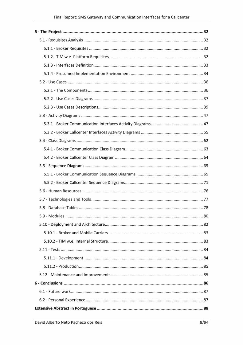
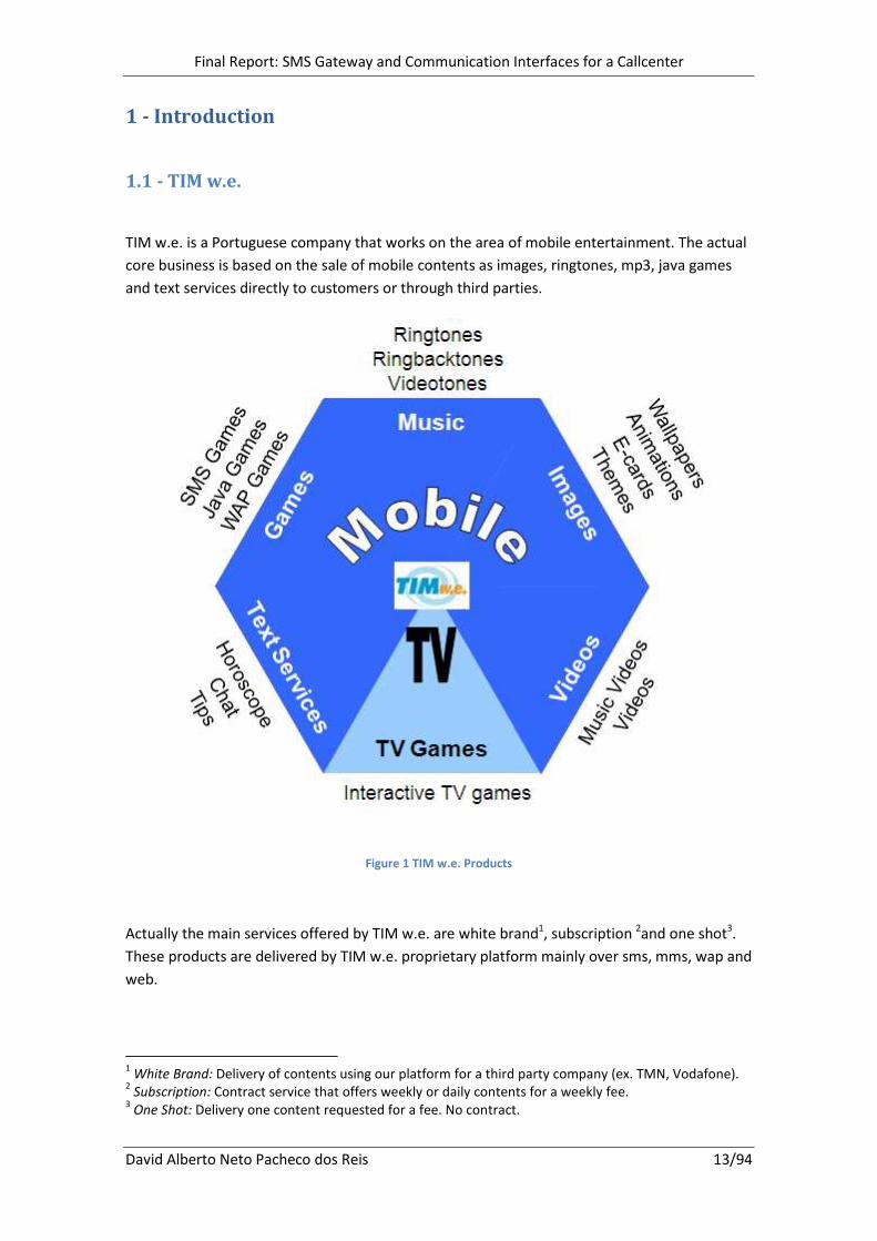
TIM w.e. is a Portuguese company that works on the area of mobile entertainment. The actual
core business is based on the sale of mobile contents as images, ringtones, mp3, java games
and text services directly to customers or through third parties.
Figure 1 TIM w.e. Products
Actually the main services offered by TIM w.e. are white brand1, subscription
2and one shot
3.
These products are delivered by TIM w.e. proprietary platform mainly over sms, mms, wap and
web.
1 White Brand: Delivery of contents using our platform for a third party company (ex. TMN, Vodafone).
2 Subscription: Contract service that offers weekly or daily contents for a weekly fee.
3 One Shot: Delivery one content requested for a fee. No contract.
Final Report: SMS Gateway and Communication Interfaces for a Callcenter
David Alberto Neto Pacheco dos Reis 14/94
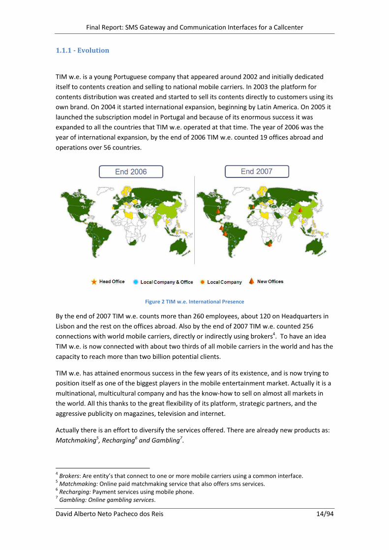
1.1.1 - Evolution
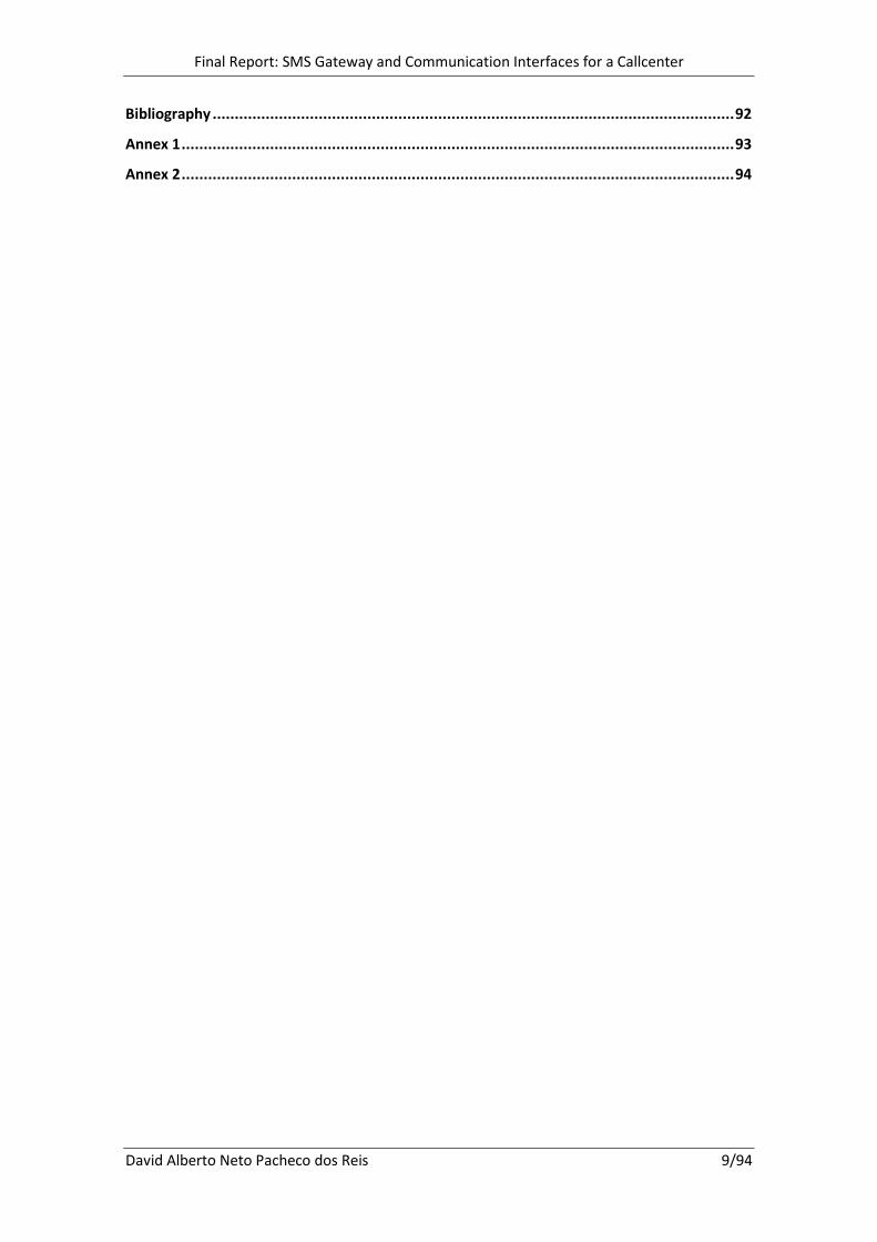
TIM w.e. is a young Portuguese company that appeared around 2002 and initially dedicated
itself to contents creation and selling to national mobile carriers. In 2003 the platform for
contents distribution was created and started to sell its contents directly to customers using its
own brand. On 2004 it started international expansion, beginning by Latin America. On 2005 it
launched the subscription model in Portugal and because of its enormous success it was
expanded to all the countries that TIM w.e. operated at that time. The year of 2006 was the
year of international expansion, by the end of 2006 TIM w.e. counted 19 offices abroad and
operations over 56 countries.
Figure 2 TIM w.e. International Presence
By the end of 2007 TIM w.e. counts more than 260 employees, about 120 on Headquarters in
Lisbon and the rest on the offices abroad. Also by the end of 2007 TIM w.e. counted 256
connections with world mobile carriers, directly or indirectly using brokers4. To have an idea
TIM w.e. is now connected with about two thirds of all mobile carriers in the world and has the
capacity to reach more than two billion potential clients.
TIM w.e. has attained enormous success in the few years of its existence, and is now trying to
position itself as one of the biggest players in the mobile entertainment market. Actually it is a
multinational, multicultural company and has the know-how to sell on almost all markets in
the world. All this thanks to the great flexibility of its platform, strategic partners, and the
aggressive publicity on magazines, television and internet.
Actually there is an effort to diversify the services offered. There are already new products as:
Matchmaking5, Recharging
6 and Gambling
7.
4 Brokers: Are entity’s that connect to one or more mobile carriers using a common interface.
5 Matchmaking: Online paid matchmaking service that also offers sms services.
6 Recharging: Payment services using mobile phone.
7 Gambling: Online gambling services.
Final Report: SMS Gateway and Communication Interfaces for a Callcenter
David Alberto Neto Pacheco dos Reis 15/94
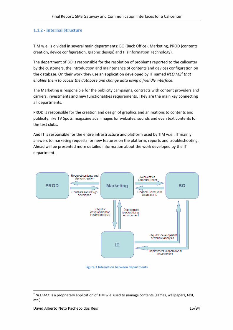
1.1.2 - Internal Structure
TIM w.e. is divided in several main departments: BO (Back Office), Marketing, PROD (contents
creation, device configuration, graphic design) and IT (Information Technology).
The department of BO is responsible for the resolution of problems reported to the callcenter
by the customers, the introduction and maintenance of contents and devices configuration on
the database. On their work they use an application developed by IT named NEO M38 that
enables them to access the database and change data using a friendly interface.
The Marketing is responsible for the publicity campaigns, contracts with content providers and
carriers, investments and new functionalities requirements. They are the main key connecting
all departments.
PROD is responsible for the creation and design of graphics and animations to contents and
publicity, like TV Spots, magazine ads, images for websites, sounds and even text contents for
the text clubs.
And IT is responsible for the entire infrastructure and platform used by TIM w.e.. IT mainly
answers to marketing requests for new features on the platform, reports and troubleshooting.
Ahead will be presented more detailed information about the work developed by the IT
department.
Figure 3 Interaction between departments
8 NEO M3: Is a proprietary application of TIM w.e. used to manage contents (games, wallpapers, text,
etc.).

Final Report: SMS Gateway and Communication Interfaces for a Callcenter
David Alberto Neto Pacheco dos Reis 16/94
1.2 - Project Description
This project describes the creation steps of a SMS Gateway and the integration of several
Callcenter interfaces to a broker in Brazil. This project has extreme importance because it was
applied to an expanding market that is expected to offer high level of product penetration. The
development of the SMS Gateway allowed TIM w.e. to offer its services to four more operators
in Brazil using this broker connection.
This entire project was integrated into an existing platform. The SMS Gateway was fully
integrated in the existing platform so it is the most dependent module since its inputs and
outputs were already predefined. The Callcenter had more liberty because it is a standalone
development, but required more analysis in order to acquire all of its requisites.
This project has an extensive analysis and design phase because it was crucial to reduce and
prevent design errors that could delay all the development and make impracticable to deliver
the interfaces on the predefined deadlines.
Before starting the development of this project there was an initial phase were all the
technologies used and all the existing projects were introduced. This has given an idea of how
the platform works and how its several components are interconnected.
Since TIM w.e. is a company that has a significant size it uses several workflow processes to
help manage the workflow of all tasks. This project was no exception and all of its tasks were
controlled using an IT workflow process.
Resuming this report displays all the phases of analysis, design, human resources involved,
technologies used, database tables used, deployment and architecture diagram and the
description of the tests applied on the system. Also very important are the descriptions of TIM
w.e. IT department and the initial work developed before the project.
Final Report: SMS Gateway and Communication Interfaces for a Callcenter
David Alberto Neto Pacheco dos Reis 17/94
1.3 - Report Structure
In the first chapter is presented some information about TIM w.e., its evolution and its internal
structure. It is also presented the project description and the report structure.
The second chapter gives information about the IT department were this project was
developed. The purpose of this chapter is to give an overview of how the department works.
The third chapter presents the work that was done before this project started. Here is
presented the main products developed at TIM w.e. and a brief explanation of their
implementation and utility. Reading this chapter will give a picture of how all the platform
works and the products it have integrated.
In the fourth chapter is described the objects, methodologies applied on this project and the
calendar for their execution.
The fifth chapter contains all the work developed on this project. Is described all software
engineering steps of the project, analysis and decisions.
In the sixth chapter are the conclusions of this project, it also contains the future works and
the personal experience.
Next is a chapter with the extensive abstract in Portuguese of this project.
The last chapter has the bibliography that was used during the development of this project.

Final Report: SMS Gateway and Communication Interfaces for a Callcenter
David Alberto Neto Pacheco dos Reis 18/94
2 - IT Department
2.1 - IT Structure
The department of IT is composed by several areas. There exist core developers, operations
developers, systems and operations architects, troubleshooting analysts, quality assurance
testers and internal support technicians. Next is presented a brief description of the most
important areas in the IT department:
Core developers: are responsible for the development of core applications and technologies
and the management of the core applications on the platform.
Operation developers: are assigned to specific countries or areas and are responsible for the
resolution of operational problems and for the development of customs projects for those
countries.
Systems and operations architects: are allocated to monitoring the systems (database,
networking, hardware, application servers, etc.) 24/7 and the deployments to production of all
developments.
Troubleshooting analysts: analyze the problems that BO and Marketing departments cannot
solve and require a deeper analysis.
Quality assurance testers: are responsible for testing all the developments made by the
developers before they move into production environment.
Internal supports technicians: do the maintenance off the entire network infrastructure and
support all the departments providing new hardware, software and solving minor issues.
2.2 - Brazil Team
This project was allocated to the operation development team of Brazil. Brazil region is a big
bet of TIM w.e. because of the high penetration rate of its products. When this project finished
it was expected more than one million clients and more than one million message transactions
per day for this connection alone. Today these values had already been achieved.
The Brazil IT team is composed by one project manager, one tester, one system and operations
architect and four operation developers. There is also an office in São Paulo with five
Marketing managers that are responsible for making the new requests for services and making
the contacts with local mobile carriers and publicity contractors.

Final Report: SMS Gateway and Communication Interfaces for a Callcenter
David Alberto Neto Pacheco dos Reis 19/94
2.3 - Development Tools
Each developer has a laptop with Windows XP and a bundle of development software. On TIM
w.e. is mainly used java programming language and some SQL for DML 9and DDL
10.
All the development is done on Eclipse Europa IDE11
with the application server Apache
Tomcat. For database is used SQL Developer tool. For tests on wap navigation is used
Openwave 12
simulator.
On the management of project versions and concurrency is used SVN13
, and for the
dependencies resolution, compilation, and deployment is used Maven 214
. Both of these tools
are fully integrated into Eclipse IDE and their use greatly improves productivity on all the
phases of the codification.
All developers use a local database oracle that makes possible to run some DDL tests and run
some services locally.
On development is also used some tools developed internally which enables the developer to
simulate the transmission of messages into our systems and to list all its flow.
Is also used several tools to access servers file systems and to open UNIX consoles on
production and development in order to access to log files and start and stop services.
2.4 - Development Environment
The IT environment is divided into four environment blocks: DEV, LAB, PRE-PROD and PROD.
DEV: this is the developer local environment, where the developer will work in and
make initial tests and debugging.
LAB: This is an optional environment, created specially to test newly created services
or connections to brokers or carriers.
PRE-PROD: This environment is a staging environment between the DEV/LAB and the
PROD environments. Here the quality team will make all quality tests to decide whether the
software has enough quality to go into the Production environment or not;
PROD: This is the final and most important environment of all. After all quality tests,
the software is passed (deployed) from the PRE-PROD to the PROD environment. When in
PROD environment, services and features can be tested live as an end-user experience.
9 DML: SQL Data Manipulation Language
10 DDL: SQL Data Definition Language
11 IDE: Integrated Development Environment
12 Openwave: Is a Phone Simulator
13 SVN: is a version control system
14 Maven: is a software tool for Java project management and build automation
Final Report: SMS Gateway and Communication Interfaces for a Callcenter
David Alberto Neto Pacheco dos Reis 20/94
In each one of the different environments (DEV, LAB, PRE-PROD and PROD), different
departments (Development, Quality Assurance and Marketing) will be able and must test the
new services and features.
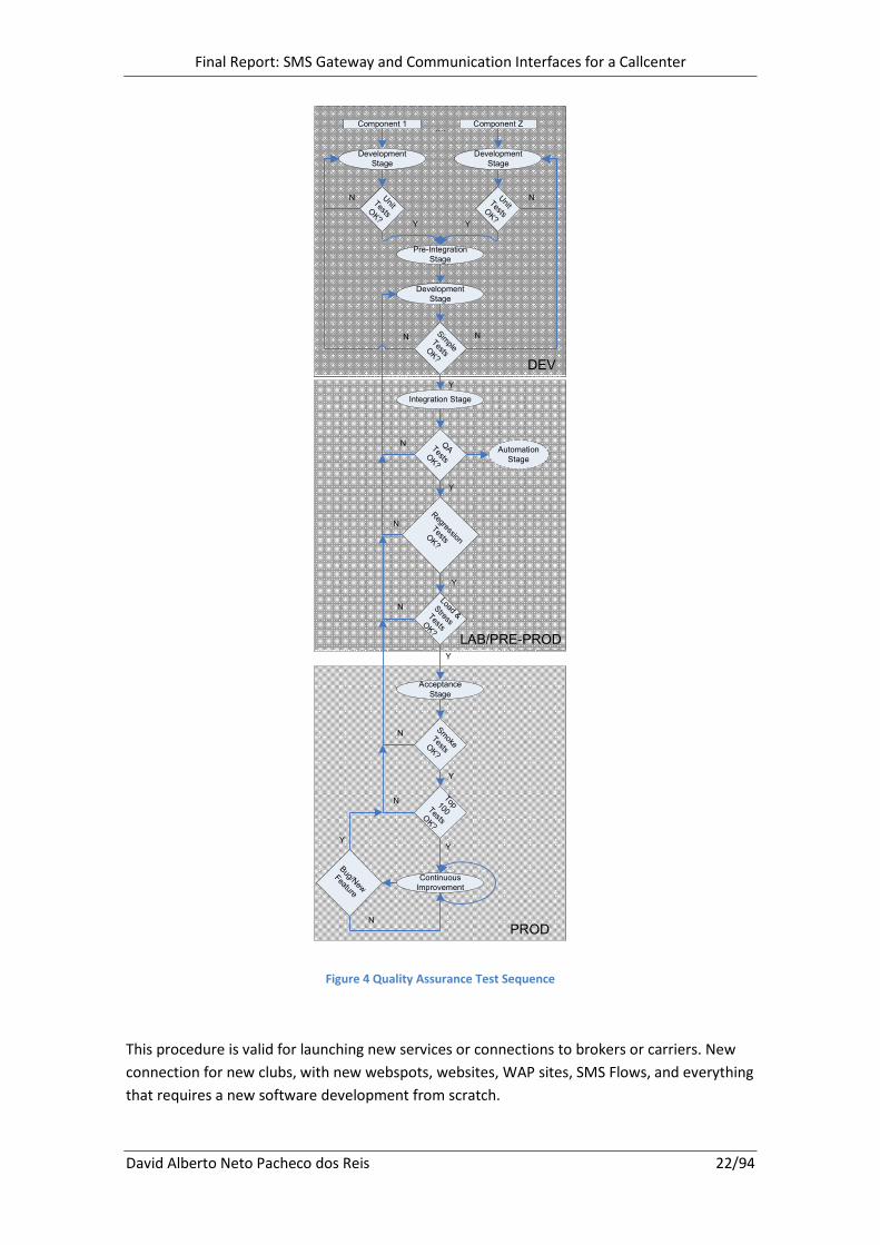
2.4.1 - Testing methodology of the New Services
The following figure 4 will explain how the testing methodology will be conducted until the
service is considered released.
Some definitions:
Component – Piece of software responsible for providing certain features, APIs, etc.
Development Stage – Stage where the software development is done.
Unit tests – In order to ensure minimum code errors engineers must run a battery of tests
before committing their code to the version control system. These tests are also known as
'pre-checkin tests'.
Pre-Integration Stage – Stage where all software components are grouped to form a product.
Simple Tests – When the implementation of a feature is in its infancy, it is useful to create a
few simple tests to check the basics. These tests are also known as isolation tests (since the
features are typically tested in isolation) or ping tests (in computing terms, to ping something
means to check that it is alive). Simple tests consist of a test as simple as a reduced test, but
designed to be easy for QA15
to use, rather than for engineers, and therefore may have the
appearance of a complicated test.
Integration Stage – Stage after the initial Pre-Integration and after running the Simple-Tests
with success.
Smoke Tests – Each day, before allowing work to begin on the code base, the previous day's
work must pass an extremely simple set of tests known as "smoke tests". Bugs found this way
is known as "smoke test blockers", and with good reason: all work is blocked until the bugs are
fixed. This is to ensure that the bugs are fixed quickly.
QA Tests – Before releasing every test case is run through a test build of the product and
manually inspected for errors. This is a very time consuming process, but (assuming the person
running the tests are familiar with them and the specification being tested) it is a very good
way of catching bugs, and setting up regressions.
Automation Tests – These tests run unattended and can therefore cover large areas of the
product with minimum effort. Automation is the holy grail of QA. Unfortunately, there are
many aspects that are hard to impossible to automate, such as printing.
15
QA: Quality Assurance
Final Report: SMS Gateway and Communication Interfaces for a Callcenter
David Alberto Neto Pacheco dos Reis 21/94
Load&Stress Tests – These tests are directly related with the Automation Tests, and intend to
reproduce the same or higher load and stress volume of requests that the product will suffer
when it goes live.
“Top 100” Tests – The web's most popular pages are regularly checked by visual inspection to
ensure that they display correctly. (It is hard, if not impossible, to automate this task, because
these pages change very, very frequently.) Bugs found through this technique are important,
because many users would encounter them should a product be released with such a defect.
In practice, many rendering issues found on top100 pages are actually caused by errors on the
pages themselves.
Continuous Improvement – Delivering incremental improvements to existing functionality.
Continuous Improvement may involve minor changes or may initiate significant pieces of work.
Planning for Continuous Improvement is the key. Sometimes projects stop funding after they
have been implemented into production, or only set aside funding for warranty or future
functional enhancements. Continuous Improvement should be explicitly planned for each
implementation increment.
Final Report: SMS Gateway and Communication Interfaces for a Callcenter
David Alberto Neto Pacheco dos Reis 22/94
DEV
Component 1 Component Z….
Development
Stage
Unit
TestsOK?
Pre-Integration
Stage
Development
Stage
Unit
TestsOK?
Development
Stage
Simple
TestsOK?
Integration Stage
QA
TestsOK?
Automation
Stage
Load &
Stress
TestsOK?
Regression
TestsOK?
Acceptance
Stage
Smoke
TestsOK?
Top 100 TestsOK?
Continuous
Improvement
Bug/New
Feature
N N
NN
N
N
N
N
N
N
YY
Y
Y
Y
Y
Y
YY
PROD
LAB/PRE-PROD
Figure 4 Quality Assurance Test Sequence
This procedure is valid for launching new services or connections to brokers or carriers. New
connection for new clubs, with new webspots, websites, WAP sites, SMS Flows, and everything
that requires a new software development from scratch.
Final Report: SMS Gateway and Communication Interfaces for a Callcenter
David Alberto Neto Pacheco dos Reis 23/94
2.5 - Workflow Management
All the workflow is managed by an online CRM 16
tool named Salesforce (www.salesforce.com).
This tool is used to create, control, assign, and measure workers performance using cases.
These cases are most of the time assigned per developer, so, all developers are always working
on different tasks, but with a common goal, the PM17
is the one responsible for allocating the
different tasks to the developers. Next will be presented a short description of an IT Operation
Development case and explained the different roles involved and the lifecycle of the case until
it is finished.
Phase of Creation: Usually the cases are created by the Marketing for new features or by the
PM for some internal development. The requester can create a case and leave it on draft until
he has all information, or it is the right time to submit to development.
Phase of Validation: The PM looks at the submitted case and assigns it to the developer. The
developer before starting the development must check that he has all information needed to
solve the case and if so he set the case status to development otherwise he sends the case to
missing data so the requester must provide the missing information.
Phase of Development: The developer solves the case and sends it to Testing status.
Phase of Testing: On this phase the case can be tested by the QA team or by the requester.
Usually using the testing team is the best option because they have rigorous testing plans. If
the case passes the tests the tester sets the case to IT Approved Status or to Stage Approved if
tested by the requester. If the case fails the tests it is sent back to development status.
Phase of Deployment: On this stage the developer sets the cases that are with the status of IT
Approved or Stage Approved to deployment status. He also has to create a new case to the
System and production architect that contains the new files, jars, etc. that are to be placed on
production environment. This new case is set as a child of the original.
Phase of Approval: On the final stage the child case created warns the requester (developer)
that it is finished. The developer then checks if the deployment is right on production, and if so
he sets the parent case to Final Approval status for the requester approval. After the case is
checked with success the requester closes the case or if not it is sent back to development
phase for corrections.
16
CRM: Customer relationship management 17
PM: Project Manager

Final Report: SMS Gateway and Communication Interfaces for a Callcenter
David Alberto Neto Pacheco dos Reis 24/94
Figure 5 IT Development Case Flow
Also as an alternative we make use of Microsoft Outlook and Skype to communicate with
coworkers and external entities.
Final Report: SMS Gateway and Communication Interfaces for a Callcenter
David Alberto Neto Pacheco dos Reis 25/94
3 - Initial Work
There exist several products offered by TIM w.e.. Before the main project all these projects
were presented and a few developments were done in order to better understand the
platform. Next will be present these main products, their finality and a few information about
its implementation.
3.1 - Webspots Project
The Webspots are in fact a website project that allows the customers to subscribe to the
products using the internet as a medium. The webspots are usually composed by three pages;
the first one is the landing page where the user inserts the mobile phone number and the
carrier. The second is the prospection page were the user inserts the password sent to him
previously via SMS. Next if he introduced the right password he proceeds to the confirmation
page where he receives the content and a confirmation message via SMS.
This website project is very adaptable because it is used in all countries TIM w.e. operates. It
can adapt texts, checkboxes, mobile selection page, banners, contents, clubs, images, flash,
basically everything.
This project was build in Java and JSP and makes use of the Apache Struts framework
(Robinson & Finkelstein, 2004). This framework allows the separation of the business layer
from the presentation layer, because it makes use of the model-view-controller paradigm. An
also very important fact of this project is that it is intensively based on properties files, which
allow its extreme customization. The downside is the complex integration of new features and
alteration of the existing ones.
3.2 - New Countries, Services and Clubs integration
The platform of TIM w.e. works mainly around countries, services and clubs.
Countries: They are the containers of services and clubs, one country can have several services
and clubs for each service.
Services: Are the identification of a specific bundle of products (ex. text products, content
products) these bundles are offered with several subscription options (Clubs). The services are
also divided by operators to facilitate the reporting and analysis systems.
Clubs: The clubs correspond to a specific type of offer for a certain type of product, for
example an offer of contents may contain the Dance Club (music tones) and Games Club (java
games). The clubs represent the final product that is purchased by the clients and is usually in
the shape of subscriptions services.
Final Report: SMS Gateway and Communication Interfaces for a Callcenter
David Alberto Neto Pacheco dos Reis 26/94
This structure of countries, services and clubs is used to enforce the independence of the
platform from the carrier connections. Using this schema all countries on the world were TIM
w.e. operates have the same internal structure. This allows any developer that understands
the platform to work on any country. This also has a major impact on the reporting and
analysis systems, because it ensures homogeneity to all the data in the system.
The creation of new countries, services or clubs is mainly done by properties files and a few
database entries. The properties files usually contain the links to the content views, texts and
the schema definitions of the clubs, but there is freedom to customization because many
services have country specific requirements. The database entries are used to define the
country, the services and the name of its configuration files. The database also contains clubs,
their keywords and the Java classes responsible for resolving the requests.
The text schemas used by the services are also very important and are used to answer to
common actions like new subscriptions, renews , cancels or already ins. These schemas are
composed of text messages and specific actions for the particular action they represent.
The Java classes mentioned before are very important on this process because they were
design to be easily extended. When the default class is not enough the developer can easily
adapt the class to the new requisites.
Behind all this is the platform that is feed by the database entries and controls the flow of the
messages (SMS) on the system. There exist several modules that monitor the system and are
responsible for invoking the classes needed to resolve the jobs.
3.3 - Wap Sites
The Wap Sites are basically web sites for mobile devices. TIM w.e. uses the Wap Sites as a
medium to deliver its contents. These sites also offer the same functionalities as the Web or
SMS service.
The Wap Sites are a Java Project composed by several classes that represent pages, these
classes are already pre-build for several tasks, like contents display, subscription and many
others. The developer doesn’t need to know WML 18
or xHTML 19
because the classes generate
it internally, the only work needed is to extend some default classes and adapt its layout. Of
course the developer as to know this project very well because there is a lot of customization,
like devices detection, phone number resolution, IP Gateway check and many others.
To resume the Wap Sites are a Java Project that is contained as a Web Project and as its layout
and specific customization on its classes, all communication are made via http and exists the
18
WML: Wireless Markup Language is a XML language intended for device that implement WAP such as
Mobile phones. 19
xHTML: eXtensible Hypertext Markup Language is a adaption of HTML based on XML
Final Report: SMS Gateway and Communication Interfaces for a Callcenter
David Alberto Neto Pacheco dos Reis 27/94
possibility to maintains sessions like a normal http connection. All the texts displayed on the
wap site are defined on properties files and its classes are resolved from database entries.
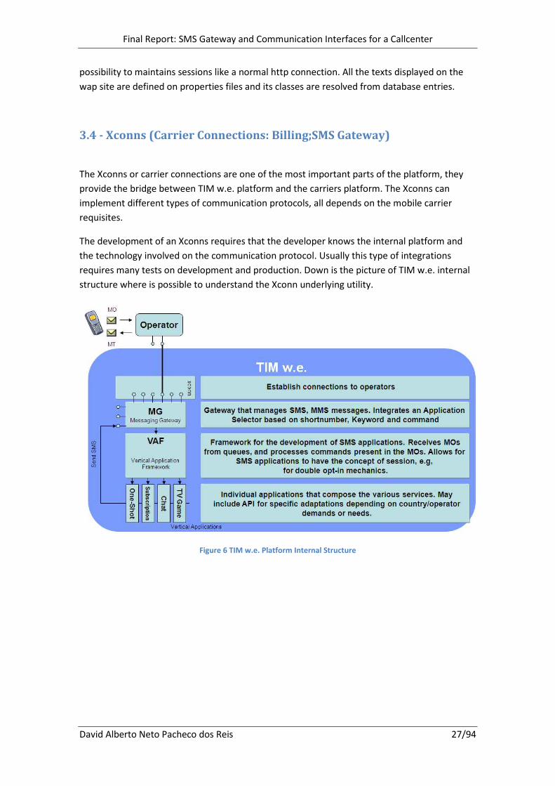
3.4 - Xconns (Carrier Connections: Billing;SMS Gateway)
The Xconns or carrier connections are one of the most important parts of the platform, they
provide the bridge between TIM w.e. platform and the carriers platform. The Xconns can
implement different types of communication protocols, all depends on the mobile carrier
requisites.
The development of an Xconns requires that the developer knows the internal platform and
the technology involved on the communication protocol. Usually this type of integrations
requires many tests on development and production. Down is the picture of TIM w.e. internal
structure where is possible to understand the Xconn underlying utility.
Figure 6 TIM w.e. Platform Internal Structure

Final Report: SMS Gateway and Communication Interfaces for a Callcenter
David Alberto Neto Pacheco dos Reis 28/94
3.5 - Initial Work Calendar
Tasks List
Name Duration Start End
Presentation 7 days 03-09-2007 11-09-2007
Adaptation 5 days 03-09-2007 07-09-2007
Working Tools and Development Environment 4 days 06-09-2007 11-09-2007
Basic Development 15 days 12-09-2007 02-10-2007
WebSpots 4 days 12-09-2007 17-09-2007
New Club Creation 6 days 18-09-2007 25-09-2007
WapSites 5 days 26-09-2007 02-10-2007
Advanced Development 21 days 03-10-2007 31-10-2007
Webspot Mechanic 5 days 03-10-2007 09-10-2007
SMS Mechanic 5 days 10-10-2007 16-10-2007
WapSite Mechanic 5 days 17-10-2007 23-10-2007
Xconns 6 days 24-10-2007 31-10-2007
Table 1 Initial Work Calendar
The Gantt map is in Annex 1.
Final Report: SMS Gateway and Communication Interfaces for a Callcenter
David Alberto Neto Pacheco dos Reis 29/94
4 – Project Objectives and Methodologies
4.1 - Objectives
The objective of this Project was to create several communication interfaces with a
telecommunications broker (www.purebros.com). This broker aggregates connections to four
mobile carriers in Brazil. The implementation of these interfaces is separated by two main
objectives: the creation of the main message exchange interfaces and the Callcenter
interfaces.
Message Exchange Interfaces: These interfaces consist of message delivery and receiving
interfaces, billing and many others. In order to build these interfaces it was necessary to follow
the integration steps of an external communication entity with the internal platform.
Callcenter Communication Interfaces: The Callcenter interfaces give the broker the capability
to deliver to the mobile carriers a tool that is used to control their customers actions and
status on TIM w.e. system. These interfaces were implemented outside the normal context of
the platform so they were very hard to implement because it was necessary to know the entire
platform and sometimes even change some aspects of the country implementation so it could
start gathering the information required by the broker and carriers.
4.2 - Methodology Approach
4.2.1 - Methodology
This project is divided in two main phases:
1. The creation of the essential communication links with the broker.
2. The creation of the Callcenter communication interfaces afterward.
Each of the phases had a standalone development. For every development step was defined a
deadline, this deadlines were very crucial and each phase deadline even more since there
exists commercial objectives to accomplish after those deadlines.
4.2.2 - Waterfall Model
This project followed a waterfall development model, with the small difference that the
specification and de design phase occurred at the same time and the implementation, testing
and maintenance were separated by the communication interfaces and callcenter interfaces.
Final Report: SMS Gateway and Communication Interfaces for a Callcenter
David Alberto Neto Pacheco dos Reis 30/94
4.2.3 - Requisites and Analysis Specification
On this phase was gathered all the requisites of the application. The Analysis had the objective
of producing the requisites specification of the application and the system specification.
4.2.4 - Project Design
On this phase was build the conceptual model of the system, divided by separated models,
more or less independent. It is also studied and defined all the system modules, their
communication and system interactions.
4.2.5 - Implementation
On this phase the project was coded to a programming language in this particular case Java. It
was also when all modules were joined and their interaction validated with the system
underlying (TIM w.e. Platform) and with the external entities (Broker).
4.2.6 - Testing
On this phase the project was tested by the Quality Assurance team with the objective of
validating that all requisites defined were achieved and the application was error and bug free.
4.2.7 - Maintenance
This phase is optional and has the objective to update the application with new features and
changes or correct possible bugs not detected during the tests.
It is not possible to estimate the time spent on this phase.

Final Report: SMS Gateway and Communication Interfaces for a Callcenter
David Alberto Neto Pacheco dos Reis 31/94
4.3 - Project Calendar
Tasks List
Name Duration Start End
Requisites and Analysis 5 days 05-11-2007 10-11-2007
System Specification 15 days 12-11-2007 01-12-2007
Project Design 20 days 03-12-2007 05-01-2008
Implementation 50 days 07-01-2008 17-05-2008
Broker Communication Interfaces 50 days 07-01-2008 15-03-2008
MO Receiving 5 days 07-01-2008 12-01-2008
MT Delivery 5 days 14-01-2008 19-01-2008
Async Notification 5 days 21-01-2008 26-01-2008
Credit Check 5 days 28-01-2008 02-02-2008
Billing 5 days 04-02-2008 09-02-2008
Subscription/Unsubscription 5 days 11-02-2008 16-02-2008
Content Delivery 5 days 18-02-2008 23-02-2008
Target Check (Phone number Carrier Check) 3 days 25-02-2008 28-02-2008
Development Tests 40 days 14-01-2008 08-03-2008
Production Tests 40 days 21-01-2008 15-03-2008
Callcenter Interfaces 50 days 10-03-2008 17-05-2008
Device Change 5 days 10-03-2008 15-03-2008
Device Information 5 days 17-03-2008 22-03-2008
Event List 5 days 24-03-2008 29-03-2008
Subscription Information 5 days 31-03-2008 05-04-2008
Send Last Content 5 days 07-04-2008 12-04-2008
Subscription 5 days 14-04-2008 19-04-2008
Unsubscription 5 days 21-04-2008 26-04-2008
Development Tests 40 days 17-03-2008 10-05-2008
Production Tests 40 days 24-03-2008 17-05-2008
Maintenance and Improvements … 17-03-2008 …
Table 2 Project Calendar
The Table 2 task list has some differences from the preliminary report because some interfaces
were optional and were decided to not implement. They were removed from this project task
list.
The duration dates were also corrected because several tasks were underestimated on the
preliminary analysis.
The Gantt map is in Annex 2.
Final Report: SMS Gateway and Communication Interfaces for a Callcenter
David Alberto Neto Pacheco dos Reis 32/94
5 - The Project
On this section is presented all the analysis and design models developed for this project, it is
also described the options and decisions taken on the implementation.
5.1 - Requisites Analysis
On the project requisites are the necessities presented by the client in this case the broker and
by the adjacent platform on which this project is build. This specification describes all the
functional aspects of the system, the structural logic, functional and all possible system
actions.
5.1.1 - Broker Requisites
This broker integration required that several communication interfaces were implemented by
TIM w.e. These interfaces are used for message exchange and control.
The broker also required that TIM w.e. supplies several communication interfaces for its
Callcenter that would allow them to monitor and control their users actions on TIM w.e.
platform. These Callcenter interfaces are used by the broker to provide a user interface to the
mobile carriers they aggregate.
For this integration the broker supplied a document that specifies all of its communication
interfaces and the formats we must implement in order to communicate.
5.1.2 - TIM w.e. Platform Requisites
Since this project have been integrated into an already existing platform, it needed to meet
some specifications and use already existing systems, databases and programming models.
This project had also to take in account the internal message flow and the reporting needs of
the underlying platform.
The Platform requisites are very important because it was needed to fulfill all the internal
requisites, in order to maintain the compatibility with all the services that exist and will be
provided using this new connection.
Final Report: SMS Gateway and Communication Interfaces for a Callcenter
David Alberto Neto Pacheco dos Reis 33/94
5.1.3 - Interfaces Definition
Below is presented a short description of all the interfaces that are going to be developed on
this project.
MO Receiving: This interface is responsible for the receiving the messages from the broker and
translation into a platform friendly format. The messages received are stored on a database.
MT Delivery: This interface as the important task of sending messages. It receives messages
that are stored in the database and translates them from the internal format to the broker’s
format and sends them.
Async Notification: The Notifications are the result status of the messages sent by TIM w.e. to
the users mobile phones. With notifications is possible to know if the messages were received
or not by the clients. This allows measuring performances and even deciding further actions to
the messages. This is only needed because the broker cannot assure synchronous message
delivery status. The Notifications are composed by two main tasks: one that receives the
messages notifications and places them on a database and the other that reads those
messages from the database and updates their final status.
Credit Check: This operation contacts the broker to acquire a ticket to bill a client and gives it
back to the system.
Billing: The Billing is used to bill a client using a ticket. Previous to use this operation the
system must acquire the valid ticket from a credit check operation.
Channel Subscription/Unsubscription: This operation is used to subscribe or unsubscribe
clients from the broker database. This is needed because some carriers of Brazil are very
restrictive on their connections and require that their direct partners maintain their client
database updated. So before any client is subscribed we must check it we can subscribe it on
the broker database.
Channel Content Delivery: This operation is called on a valid daytime to deliver content for
several channels (products). This operation works like a broadcast and when called the broker
sends a message to all clients that belong to a specified channel.
Target Check: This operation allows the system to validate a user mobile carrier on the broker,
this is very important for services on the web or offline, on which the user gives its phone
number and we must validate it so we can sent the messages to the right carrier.
Device Information: This operation allows the broker to retrieve from TIM w.e. customer
database the device information of a client.
Device Change: This operation allows the broker to define a client device on TIM w.e customer
database.
Final Report: SMS Gateway and Communication Interfaces for a Callcenter
David Alberto Neto Pacheco dos Reis 34/94
Event List: This operation allows the broker to retrieve all events information from a specific
customer for a specific time period. This information must be parsed so it fits the broker
format requisites.
Subscription Information: This operation is similar to the Event List but provides more detailed
information about the customer, because it also retrieves subscription information from the
subscriptions database.
Send Last Content: This operation allows the broker to resend the last content (message) from
a certain service (product) to the client. This is possible because all messages are saved on the
database and can be retrieved and resent.
Subscription: This operation can be used by the broker to subscribe a client to a certain service
on TIM w.e. platform. This operation executes several steps that are required when creating a
new subscription.
Unsubscription: This operation can be used by the broker to unsubscribe a client from a
certain service on TIM w.e. platform. It will proceed with all operations needed to cancel a
subscription.
5.1.4 - Presumed Implementation Environment
Since this project is based on an API20
supplied by the broker it was decided to specify how all
these components would be implemented on the TIM w.e. platform. This task is necessary
before further analysis because already exists a procedure and several APIs to help implement
and integrate new interfaces on TIM w.e. platform.
The Communication interfaces have been integrated onto the existing platform and the
Callcenter interfaces have been implemented as a standalone service, but using already
existing APIs.
All the design was produced based on the next assumptions.
20
API - Application Programming Interface
Final Report: SMS Gateway and Communication Interfaces for a Callcenter
David Alberto Neto Pacheco dos Reis 35/94
5.1.4.1 – Objects and Package Types Decision
Next is presented the description of the objects and package types that were used by each
interface.
Message Exchange Servlets
• MO Receiving
• Async Notification Receiver
Callcenter Servlets
• Device Information
• Device Change
• Event List
• Subscription Information
• Send Last Content
• Subscription
• Unsubscription
The servlets are objects that receive and generate a response based on a request (http). These
objects run inside Web Containers that run on application servers.
Purebros API:
• Target Check
• Billing
• Credit Check
• Channel Subscription/Unsubscription
The Purebros API corresponds to a package of several java classes that will allow several
operations on the broker. This package will be used by any application that needs it.
IXconn Interface
• MT Delivery
The IXconn interface is used by TIM w.e. platform and represents the interfaces that a
communication class should implement. This Interface in particular is used to specify the
interfaces for the MT Delivery.
BroadCast Extended Object
• Channel Content Delivery
The broadcast object is used by TIM w.e. platform and implements a message broadcast
mechanism. This object can be extended and reused for custom functionalities.
Final Report: SMS Gateway and Communication Interfaces for a Callcenter
David Alberto Neto Pacheco dos Reis 36/94
PosPr Extended Object
• Notification Monitor
The Post Processing object is used by TIM w.e. platform and implements common
functionalities used after an action has been completed, on this particular case the message
confirmation. This object can be extended and reused for custom functionalities.
Properties Files
• All the volatile information as login, passwords and the services mapping with the
broker are stored on these files.
These text files contain definitions that change very often. They are loaded on demand into the
classes that need to read their information. On TIM w.e. these files are heavily used.
5.2 - Use Cases
The use case diagram describes the functionalities of the proposed system. These diagrams
have the objective of describing the functional requisites of the system and delivering a
consistent and clear vision of what the system should do.
To represent all this information is used UML21
(Nunes & O'Neill, 2004). This modeling
language assists on the design of the system and has the capacity to represent the actions and
communications between the several objects that define the system.
5.2.1 - The Components
All the design was made using two possible actors for the actions.
Broker: Represent the role done by the broker as an external entity.
System: Represent the role done by the TIM w.e. platform as an internal entity.
Use Cases: Represent the possible actions done by the actors.
21
UML - Unified Modeling Language

Final Report: SMS Gateway and Communication Interfaces for a Callcenter
David Alberto Neto Pacheco dos Reis 37/94
5.2.2 - Use Cases Diagrams
5.2.2.1 - Broker Communication Use Case Diagram:
Figure 7 Broker Communication Interfaces Use Case Diagram
On this diagram there are several actions and reactions between the actor Broker and the
system.
None of these use cases are dependent because all represent possible asynchronous actions
that can be activated by one of the sides.
Final Report: SMS Gateway and Communication Interfaces for a Callcenter
David Alberto Neto Pacheco dos Reis 38/94
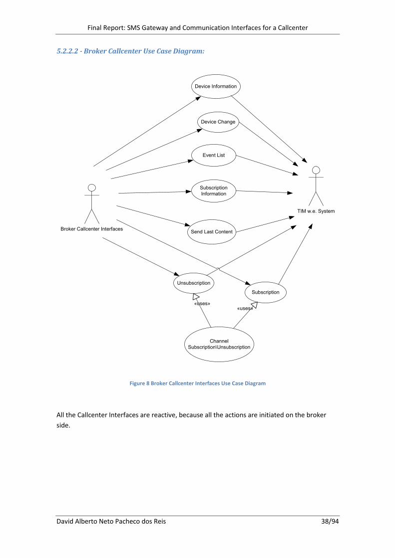
5.2.2.2 - Broker Callcenter Use Case Diagram:
Broker Callcenter InterfacesSend Last Content
Subscription
Unsubscription
Subscription
Information
Event List
Device Change
Device Information
Channel
Subscription\Unsubscription
«uses»«uses»
TIM w.e. System
Figure 8 Broker Callcenter Interfaces Use Case Diagram
All the Callcenter Interfaces are reactive, because all the actions are initiated on the broker
side.
Final Report: SMS Gateway and Communication Interfaces for a Callcenter
David Alberto Neto Pacheco dos Reis 39/94
5.2.3 - Use Cases Descriptions
5.2.3.1 - Broker Communication Interfaces Use Cases
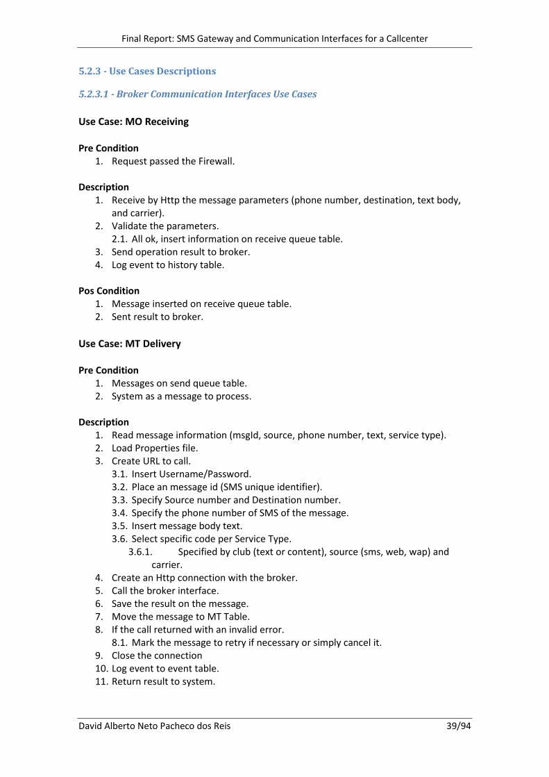
Use Case: MO Receiving
Pre Condition
1. Request passed the Firewall.
Description
1. Receive by Http the message parameters (phone number, destination, text body,
and carrier).
2. Validate the parameters.
2.1. All ok, insert information on receive queue table.
3. Send operation result to broker.
4. Log event to history table.
Pos Condition
1. Message inserted on receive queue table.
2. Sent result to broker.
Use Case: MT Delivery
Pre Condition
1. Messages on send queue table.
2. System as a message to process.
Description
1. Read message information (msgId, source, phone number, text, service type).
2. Load Properties file.
3. Create URL to call.
3.1. Insert Username/Password.
3.2. Place an message id (SMS unique identifier).
3.3. Specify Source number and Destination number.
3.4. Specify the phone number of SMS of the message.
3.5. Insert message body text.
3.6. Select specific code per Service Type.
3.6.1. Specified by club (text or content), source (sms, web, wap) and
carrier.
4. Create an Http connection with the broker.
5. Call the broker interface.
6. Save the result on the message.
7. Move the message to MT Table.
8. If the call returned with an invalid error.
8.1. Mark the message to retry if necessary or simply cancel it.
9. Close the connection
10. Log event to event table.
11. Return result to system.

Final Report: SMS Gateway and Communication Interfaces for a Callcenter
David Alberto Neto Pacheco dos Reis 40/94
Pos Condition
1. Message execution result sent to system.
Use Case: Async Notification
Pre Condition
1. Request passed the Firewall.
2. Request as valid parameters.
Description
1. Receive by Http the notification parameters (SMS unique identifier, error code).
2. Save the parameters to the notification table.
3. A notification monitor reads the pending notifications.
3.1. Save the result error on the message on the sent queue table.
3.2. Retry the message if existed and error and if the carrier allows, this is done
moving the message back to the send queue table.
4. Resolve phone number.
5. Log notification to event table.
Pos Condition
1. Message delivery status updated.
Use Case: Credit Check
Pre Condition
1. Client requested a payed service.
2. System calls the API with valid parameters.
Description
1. Receives the target phone number, service type and the request source.
2. Load Properties file.
3. Create URL to call.
3.1. Insert Username/Password.
3.2. Add the target phone number.
3.3. Specify the type of service to validate.
3.4. Specify the request source (sms,web,wap, callcenter).
4. Create an Http connection with the broker.
5. Execute the call.
6. Close the connection.
7. Log result to event table.
8. Verify the returned Credit Check Ticket.
8.1. If is valid return the Credit Check Ticket.
8.2. If invalid return -1.
Pos Condition
1. Returned the Credit Check Id.
Final Report: SMS Gateway and Communication Interfaces for a Callcenter
David Alberto Neto Pacheco dos Reis 41/94
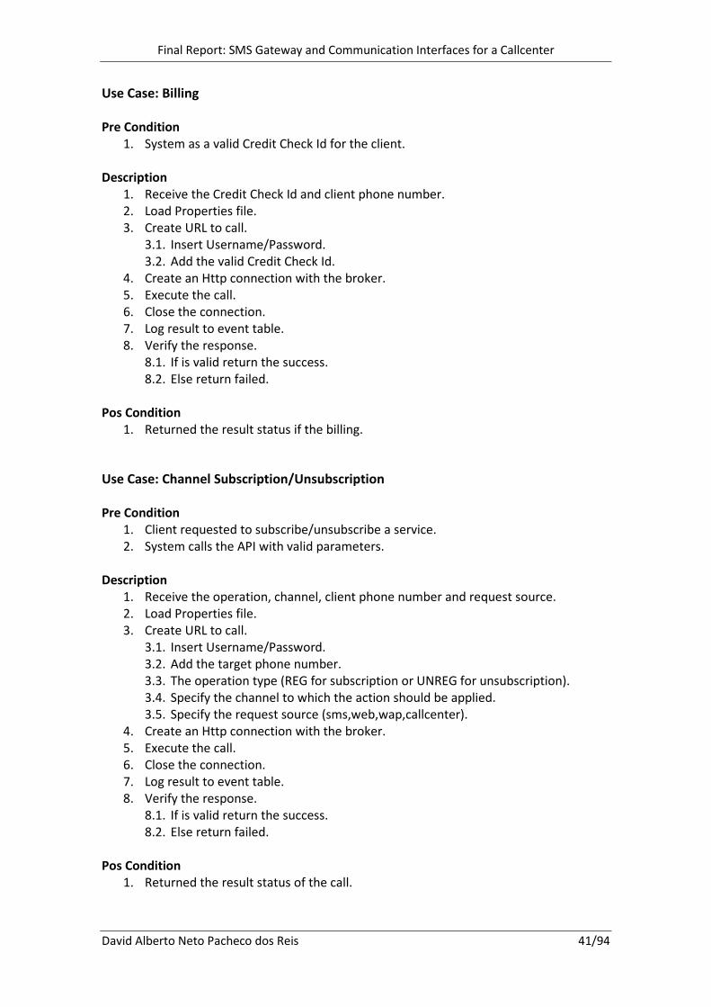
Use Case: Billing
Pre Condition
1. System as a valid Credit Check Id for the client.
Description
1. Receive the Credit Check Id and client phone number.
2. Load Properties file.
3. Create URL to call.
3.1. Insert Username/Password.
3.2. Add the valid Credit Check Id.
4. Create an Http connection with the broker.
5. Execute the call.
6. Close the connection.
7. Log result to event table.
8. Verify the response.
8.1. If is valid return the success.
8.2. Else return failed.
Pos Condition
1. Returned the result status if the billing.
Use Case: Channel Subscription/Unsubscription
Pre Condition
1. Client requested to subscribe/unsubscribe a service.
2. System calls the API with valid parameters.
Description
1. Receive the operation, channel, client phone number and request source.
2. Load Properties file.
3. Create URL to call.
3.1. Insert Username/Password.
3.2. Add the target phone number.
3.3. The operation type (REG for subscription or UNREG for unsubscription).
3.4. Specify the channel to which the action should be applied.
3.5. Specify the request source (sms,web,wap,callcenter).
4. Create an Http connection with the broker.
5. Execute the call.
6. Close the connection.
7. Log result to event table.
8. Verify the response.
8.1. If is valid return the success.
8.2. Else return failed.
Pos Condition
1. Returned the result status of the call.

Final Report: SMS Gateway and Communication Interfaces for a Callcenter
David Alberto Neto Pacheco dos Reis 42/94
Use Case: Channel Content Delivery
Pre Condition
1. Executed on valid daytime.
Description
1. Check the event table for Successful Channel Content Delivery calls today.
2. Load Properties file.
3. Create several URL’s to call with uncalled or unsuccessful channel content
deliveries today.
3.1. Insert Username/Password on each.
3.2. Specify the channel to which the action should be applied.
3.3. Add the message body text.
4. Create an Http connection with the broker.
5. Execute the calls.
6. Close the connection.
7. Save all the responses to the event tab associating the channel and its call result.
Pos Condition
1. All valid channels called and their responses saved to the database.
Use Case: Target Check (Phone number Carrier Check)
Pre Condition
1. System wants to check the validity of the phone number.
Description
1. Receive the phone number.
2. Load Properties file.
3. Create URL to call.
3.1. Insert Username/Password.
3.2. Add the target phone number.
4. Create an Http connection with the broker.
5. Execute the call.
6. Close the connection.
7. Verify the response.
7.1. Translate the carrier name to the internal carrier numeration.
Pos Condition
1. Returned the internal carrier number of a specific phone number.
Final Report: SMS Gateway and Communication Interfaces for a Callcenter
David Alberto Neto Pacheco dos Reis 43/94
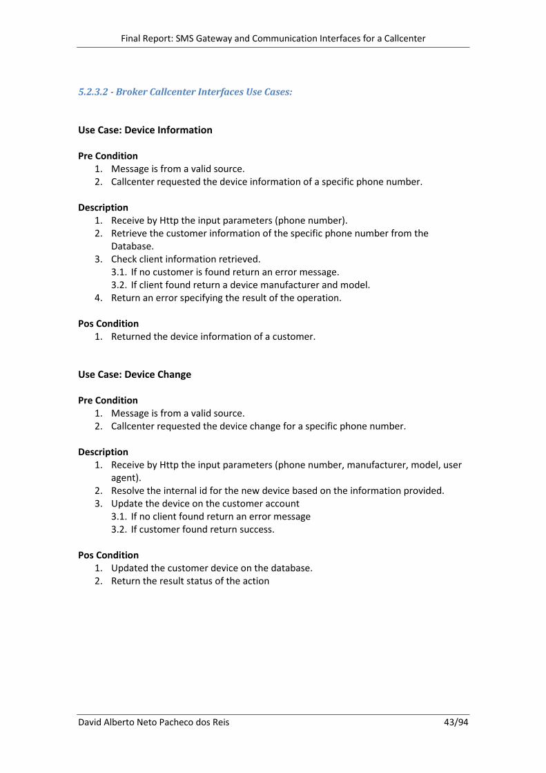
5.2.3.2 - Broker Callcenter Interfaces Use Cases:
Use Case: Device Information
Pre Condition
1. Message is from a valid source.
2. Callcenter requested the device information of a specific phone number.
Description
1. Receive by Http the input parameters (phone number).
2. Retrieve the customer information of the specific phone number from the
Database.
3. Check client information retrieved.
3.1. If no customer is found return an error message.
3.2. If client found return a device manufacturer and model.
4. Return an error specifying the result of the operation.
Pos Condition
1. Returned the device information of a customer.
Use Case: Device Change
Pre Condition
1. Message is from a valid source.
2. Callcenter requested the device change for a specific phone number.
Description
1. Receive by Http the input parameters (phone number, manufacturer, model, user
agent).
2. Resolve the internal id for the new device based on the information provided.
3. Update the device on the customer account
3.1. If no client found return an error message
3.2. If customer found return success.
Pos Condition
1. Updated the customer device on the database.
2. Return the result status of the action

Final Report: SMS Gateway and Communication Interfaces for a Callcenter
David Alberto Neto Pacheco dos Reis 44/94
Use Case: Event List
Pre Condition
1. Message is from a valid source.
2. Callcenter requested the event list for a specific phone number.
Description
1. Receive by Http the input parameters (phone number, start date, end date).
2. Resolve the customer id for the phone number sent.
3. Retrieve all customer events from the events table for the time period specified.
3.1. If no data found send error message
3.2. Else transform the information to the format requested by the broker and
send.
Pos Condition
1. Returned the information for the requested phone number within a specified time
period.
Use Case: Subscription Information
Pre Condition
1. Message is from a valid source.
2. Callcenter requested the Subscription Information for a specific phone number.
Description
1. Receive by Http the input parameters (phone number).
2. Resolve the customer id for the phone number sent.
3. Retrieve all customer subscriptions/unsubscriptions events from event table and
subscription information from subscription table.
3.1. If no data found send error message
3.2. Otherwise compile the information to the format requested by the broker and
send.
Pos Condition
1. Returned the information of all subscriptions for the requested phone number.
Final Report: SMS Gateway and Communication Interfaces for a Callcenter
David Alberto Neto Pacheco dos Reis 45/94
Use Case: Send Last Content
Pre Condition
1. Message is from a valid source.
2. Callcenter requested the resend of content for a specific phone number.
Description
1. Receive by Http the input parameters (phone number, category, service type).
2. Retrieves from the event table the last content message send for this phone
number filtered by service type.
3. Validates the message.
3.1. No message found, return error
3.2. Else reinsert the message into the send queue table and return success.
Pos Condition
1. Resented the content to the customer.
2. Returned the status of the operation to the Callcenter.
Use Case: Subscription
Pre Condition
1. Message is from a valid source.
2. Callcenter requested to subscribe a phone number to a service.
Description
1. Receive by Http the input parameters (phone number, service type).
2. Resolve the customer id from the phone number received.
3. Create the customer if he doesn’t exist
4. Subscribe the customer to the club with the corresponding service type
4.1. If is a channel Subscription include : Channel Subscription/Unsubscription
5. Send customer the congratulations messages associated with the club.
6. Return the result of the operation to the Callcenter
Pos Condition
1. Customer subscribed the club and congratulations messages sent.
2. Returned the result of the operation to the Callcenter

Final Report: SMS Gateway and Communication Interfaces for a Callcenter
David Alberto Neto Pacheco dos Reis 46/94
Use Case: Unsubscription
Pre Condition
1. Message is from a valid source.
2. Callcenter requested to subscribe a phone number to a service.
Description
1. Receive by Http the input parameters (phone number, service type).
1. Resolve the customer id from the phone number received.
2. Unsubscribe the customer from the club with the corresponding service type
2.1. If is a channel unsubscription include : Channel Subscription/Unsubscription
3. Send customer the cancelation messages associated with the club.
4. Return the result of the operation to the Callcenter
Pos Condition
1. Customer unsubscribed the club and cancelation messages sent.
2. Returned the result of the operation to the Callcenter

Final Report: SMS Gateway and Communication Interfaces for a Callcenter
David Alberto Neto Pacheco dos Reis 47/94
5.3 - Activity Diagrams
The activity diagrams represent all the workflow done by a class. The following diagrams
represent all the use cases described above.
5.3.1 - Broker Communication Interfaces Activity Diagrams
5.3.1.1 - MO Receiving
Figure 9 MO Receiving Activity Diagram
This diagram represents all the actions from the message receiving process involved between
the systems. The MO Receiving listens to messages sent from the broker and processes them
following the specified actions on the diagram.

Final Report: SMS Gateway and Communication Interfaces for a Callcenter
David Alberto Neto Pacheco dos Reis 48/94
5.3.1.2 - MT Delivery
MT Delivery Broker
Load Pending Messages Read Message Information
Add Retry to Message on Send Queue
Resolve Result Send Result
Remove Msg From Send Queue
Insert Message on MT Table
Create URL to Call
Call Broker Resolve Call
Add Retry To Message
Remove Message
Insert MT
Resolve Result
Log Event to Events Table
Gather Event Information
Send Result Information
[Fail]
[Success]
System
Read Properties File
Figure 10 MT Delivery Activity Diagram
This diagram represents the actions taken to send the messages to the broker. This action is
initiated by the system that injects the messages into the MT Delivery class. This class will send
the message and take several actions depending on the result sent by the broker.

Final Report: SMS Gateway and Communication Interfaces for a Callcenter
David Alberto Neto Pacheco dos Reis 49/94
5.3.1.3 - Async Notification
Async Notification Receiver System
Send Notification Read Notification Parameters Insert Notification on Table
Prepare ResultResolve Result
Get NotificationGet Pending Notification from table
Evaluate Notification Result
Update Message Status on Table
Move Message to Send Queue Table
Get Message Phone Number
Resolve Phone Number on Customer Table
Log Event to Events Table
Gather Event Information
Broker Notification
Monitor
[Success]
[Failed]
Figure 11 Async Notification Activity Diagram
On this diagram is displayed the actions taken by the notifications receiving interface and the
notification monitor that updates the message status on the database.

Final Report: SMS Gateway and Communication Interfaces for a Callcenter
David Alberto Neto Pacheco dos Reis 50/94
5.3.1.4 - Credit Check
Credit CheckSystem
Request to Check User Credits Resolve parameters to Call
Parse Ticket Generate Response
Create URL to Call
Call Broker Check Ticket Validity
Evaluate Ticket
Return Failed Ticket
Log Event to Events Table Gather Event Information
Return Valid TicketResolve Result
Broker
[Invalid Ticket]
[Valid Ticket]
Read Properties File
Figure 12 Credit Check Activity Diagram
This diagram represents the actions taken to get a ticket from the broker to bill a client. This
process is initiated by the system and ends with the valid ticket or error ticket returned back to
the system.
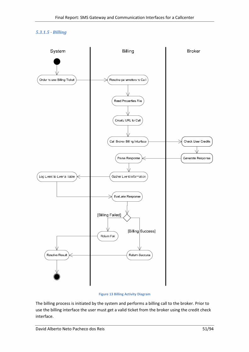
Final Report: SMS Gateway and Communication Interfaces for a Callcenter
David Alberto Neto Pacheco dos Reis 51/94
5.3.1.5 - Billing
Figure 13 Billing Activity Diagram
The billing process is initiated by the system and performs a billing call to the broker. Prior to
use the billing interface the user must get a valid ticket from the broker using the credit check
interface.

Final Report: SMS Gateway and Communication Interfaces for a Callcenter
David Alberto Neto Pacheco dos Reis 52/94
5.3.1.6 - Channel Subscription/Unsubscription
Channel Subscription/
Unsubscription
System
Order to use Subscribe/Unsubscribe Phone Resolve parameters to Call
Parse Response Generate Response
Create URL to Call
Call Broker Sub/Unsub Interface Validate Operation
Evaluate Response
Return Fail and Error
Log Event to Events Table Gather Event Information
Return Success and ErrorResolve Result
Broker
[Failed]
[Success]
Read Properties File
Figure 14 Channel Subscription/Unsubscription Activity Diagram
This process represents the actions taken to subscribe or unsubscribe a user on the broker
database. Only if the broker accepts the subscription or unsubscription TIM w.e. can perform
the same action on its database. This is true because the broker has the master client database
on their side and TIM w.e. database must be synchronized with it.

Final Report: SMS Gateway and Communication Interfaces for a Callcenter
David Alberto Neto Pacheco dos Reis 53/94
5.3.1.7 - Channel Content Delivery
Figure 15 Channel Content Delivery Activity Diagram
This task performs a broadcast to all the users of a service with a specified message. It also
controls the executions per day, per channel and per day time in order to avoid double
broadcasts or broadcasts on invalid date time.
This broadcast represents only a call from TIM w.e. platform; is the broker that effectively
sends the message to each of the clients.
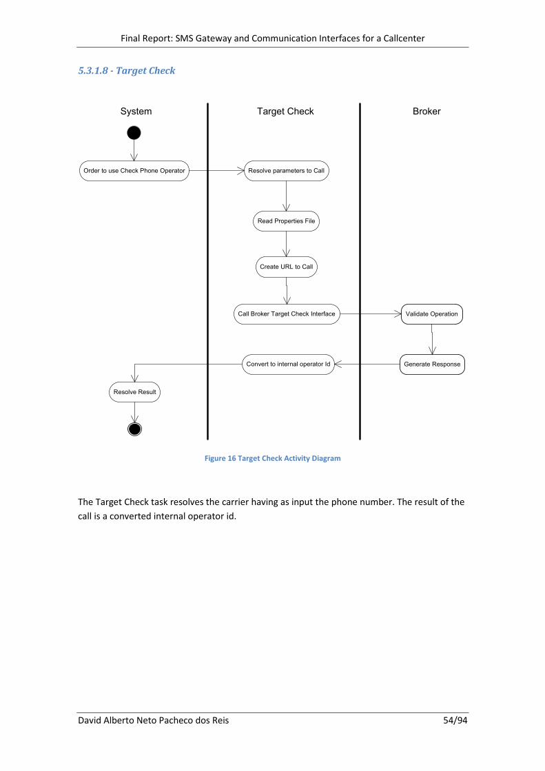
Final Report: SMS Gateway and Communication Interfaces for a Callcenter
David Alberto Neto Pacheco dos Reis 54/94
5.3.1.8 - Target Check
Target CheckSystem
Order to use Check Phone Operator Resolve parameters to Call
Convert to internal operator Id Generate Response
Create URL to Call
Call Broker Target Check Interface Validate Operation
Resolve Result
Broker
Read Properties File
Figure 16 Target Check Activity Diagram
The Target Check task resolves the carrier having as input the phone number. The result of the
call is a converted internal operator id.
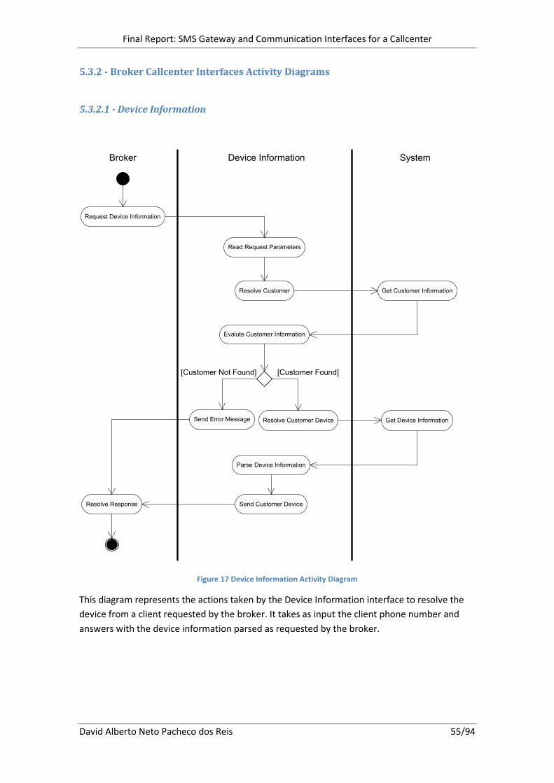
Final Report: SMS Gateway and Communication Interfaces for a Callcenter
David Alberto Neto Pacheco dos Reis 55/94
5.3.2 - Broker Callcenter Interfaces Activity Diagrams
5.3.2.1 - Device Information
Broker Device Information System
Request Device Information
Read Request Parameters
Evalute Customer Information
Send Customer DeviceResolve Response
Get Customer InformationResolve Customer
Send Error Message Resolve Customer Device Get Device Information
Parse Device Information
[Customer Found][Customer Not Found]
Figure 17 Device Information Activity Diagram
This diagram represents the actions taken by the Device Information interface to resolve the
device from a client requested by the broker. It takes as input the client phone number and
answers with the device information parsed as requested by the broker.

Final Report: SMS Gateway and Communication Interfaces for a Callcenter
David Alberto Neto Pacheco dos Reis 56/94
5.3.2.2 - Device Change
SystemDevice ChangeBroker
Request Device Change
Read Request Parameters
Update Customer
Resolve Response
Get Device IdentificationResolve Device
Send Error Message
Send Success Message
Update Customer Device
Evalute Operation Result
[Customer Found]
[Customer Not Found]
Figure 18 Device Change Activity Diagram
This interface changes the device of a customer directly on TIM w.e. database. It takes as input
the client phone number and the new device information. As output it sends the result of the
execution.
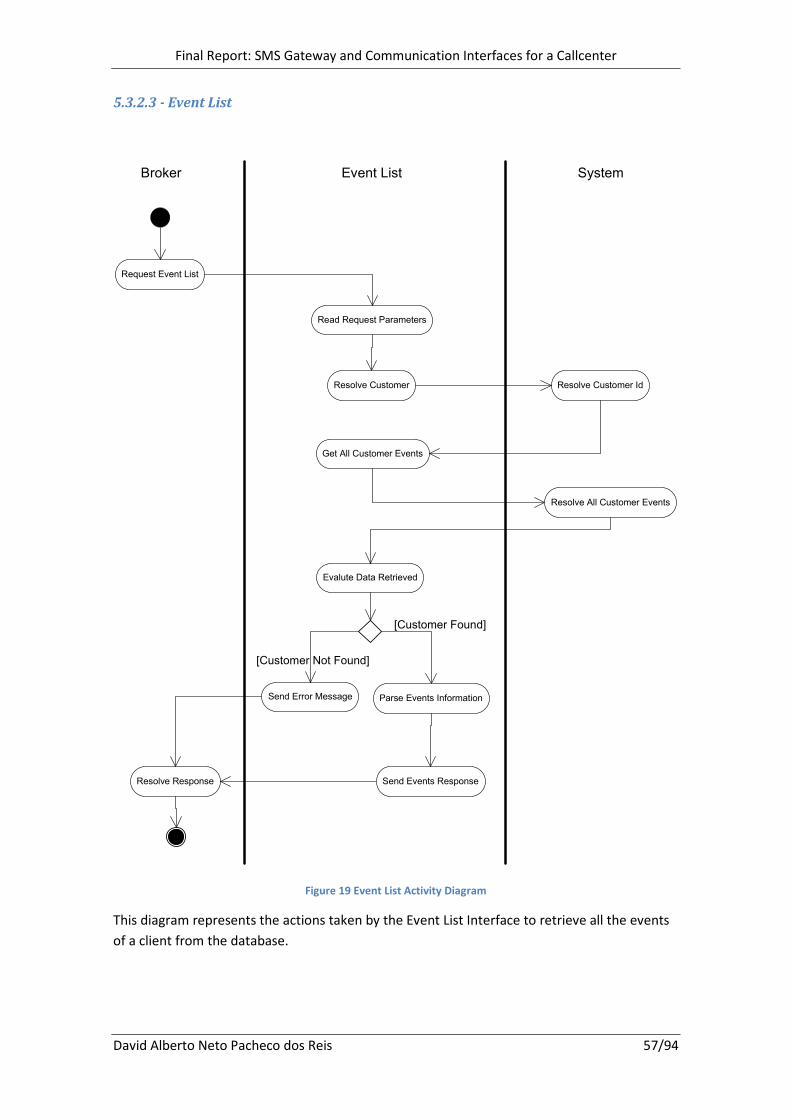
Final Report: SMS Gateway and Communication Interfaces for a Callcenter
David Alberto Neto Pacheco dos Reis 57/94
5.3.2.3 - Event List
SystemEvent ListBroker
Request Event List
Read Request Parameters
Get All Customer Events
Resolve Response
Resolve Customer IdResolve Customer
Send Error Message
Send Events Response
Resolve All Customer Events
Evalute Data Retrieved
Parse Events Information
[Customer Not Found]
[Customer Found]
Figure 19 Event List Activity Diagram
This diagram represents the actions taken by the Event List Interface to retrieve all the events
of a client from the database.

Final Report: SMS Gateway and Communication Interfaces for a Callcenter
David Alberto Neto Pacheco dos Reis 58/94
5.3.2.4 - Subscription Information
Figure 20 Subscription Information Activity Diagram
The Subscription Information task is similar to the Event List with the difference that it has a
different information parsing and as more information about the subscription of the user.
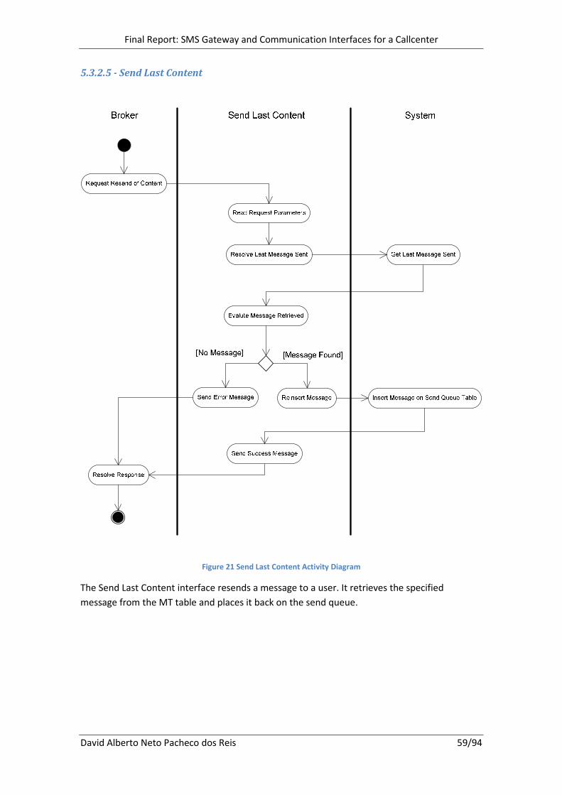
Final Report: SMS Gateway and Communication Interfaces for a Callcenter
David Alberto Neto Pacheco dos Reis 59/94
5.3.2.5 - Send Last Content
Figure 21 Send Last Content Activity Diagram
The Send Last Content interface resends a message to a user. It retrieves the specified
message from the MT table and places it back on the send queue.

Final Report: SMS Gateway and Communication Interfaces for a Callcenter
David Alberto Neto Pacheco dos Reis 60/94
5.3.2.6 - Subscription
Figure 22 Subscription Activity Diagram
This interface represents the actions taken to subscribe a user on TIM w.e. database using the
callcenter interface. It also sends the client the messages defined for the specified service.
The answer sent to the broker is the result of the operation.

Final Report: SMS Gateway and Communication Interfaces for a Callcenter
David Alberto Neto Pacheco dos Reis 61/94
5.3.2.7 - Unsubscription
SystemUnsubscriptionBroker
Unsubscribe Client Read Request Parameters
Resolve Response
Get Customer Id from TableResolve Customer ID
Verify Customer ID
Unsubscribe User on PB
Send Failed Message
Call PB Sub/Unsub API
Send Success Message
Evaluate PB Response
Cancel Subscription Cancel Subscription on Table
Send Cancel Schema Messages
Add Schema Messages to Queue Table
[Not Found] [Found Customer]
[Success]
[Failed]
Figure 23 Unsubscription Activity Diagram
This interface represents the actions taken to unsubscribe a user on TIM w.e. database using
the callcenter interface. It also sends the client the messages defined for a cancelation.
The answer sent to the broker is the result of the operation.

Final Report: SMS Gateway and Communication Interfaces for a Callcenter
David Alberto Neto Pacheco dos Reis 62/94
5.4 - Class Diagrams
The following diagrams represent the object structure of this project. For each object is
described its attributes, operations and connections to other objects.
Note: The gray objects represent existing objects used by the current project but are out of its
domain. They are displayed to better understand their connections with the current project
objects.

Final Report: SMS Gateway and Communication Interfaces for a Callcenter
David Alberto Neto Pacheco dos Reis 63/94
5.4.1 - Broker Communication Class Diagram
+init()
+doGet()
-readParameters()
-addToQueue()
-getConfiguration()
<<Controller>> MO Receiving
+init()
+doGet()
Http Servlet
+receiveSMS()
+xconnKey
+status
+origin
+destination
+message
+recDate
+operator
REC sms
1*
+start()
+sendSMS()
+stop()
-getConfiguration()
-resolveServiceType()
-gatherEventInfo()
-generateURL()
-readProperties()
-username
-password
<<Controller>> MT Delivery
+start()
+sendSMS()
+stop()
«interface»
IXconn
+addEvent()
+id
+type
+date
+service_type
+source
+phone_number
+op_id
+result_code
Purebros Event
1
*
+init()
+doGet()
-readParameters()
<<Controller>> Async Notification Receiver
+addNotification()
-ID
-Msg_ID
-Status
Notification
1 *
+init()
+doGet()
-readParameters()
-resolveNotification()
<<Controller>> Notification Monitor
+creditCheck()
-generateURL()
-parseResponse()
-gatherEventInfo()
-readProperties()
-ticket
-username
-password
<<Controller>> Credit Check
1
*
+billCustomer()
-generateURL()
-parseResponse()
-gatherEventInfo()
-readProperties()
-username
-password
<<Controller>> Billing
1
*
+subscribeUnsubCustomer()
-generateURL()
-parseResponse()
-gatherEventInfo()
-readProperties()
-username
-password
<<Controller>> Channel Subscription/Unsubscription
1*
+targetCheck()
-generateURL()
-parseResponse()
-readProperties()
-username
-password
<<Controller>> Target Check
-generateURLS()
-parseResponses()
-validateExecutionTime()
-resolveMissingExecutions()
-callUnexecutedChannels()
-getChannelsSuccessfullyExecutedToday()
-readProperties()
-username
-password
<<Controller>> Channel Content Delivery
1
*
+insertRecQueue()
+insertSendQueue()
+removeSendQueue()
+getMessageSendQueue()
+removeMsgSendQueue()
+addRetryMessage()
+insertNotification()
+addRetryToMsg()
+insertNotification()
+getNotification()
+updateMTStatus()
+getMessageId()
+sendSchemaMessages()
+InsertMT()
<<Controller>> Message Gateway
+addHistoryEvent()
+getCustomerPhoneNumber()
+getCustomerId()
+getCustomerDeviceId()
+updateCustomerDevice()
+createNewSubscription()
+createCustomer()
+cancelSubscription()
+getSubscriptionInformation()
<<Controller>> CRM
+addEventToTable()
+getUnexecutedChannels()
+getAllEvents()
+getLastMessageSent()
<<Controller>> Purebros DAO
Figure 24 Broker Communication Class Diagram
This class diagram represents the object structure of the broker communication interfaces.
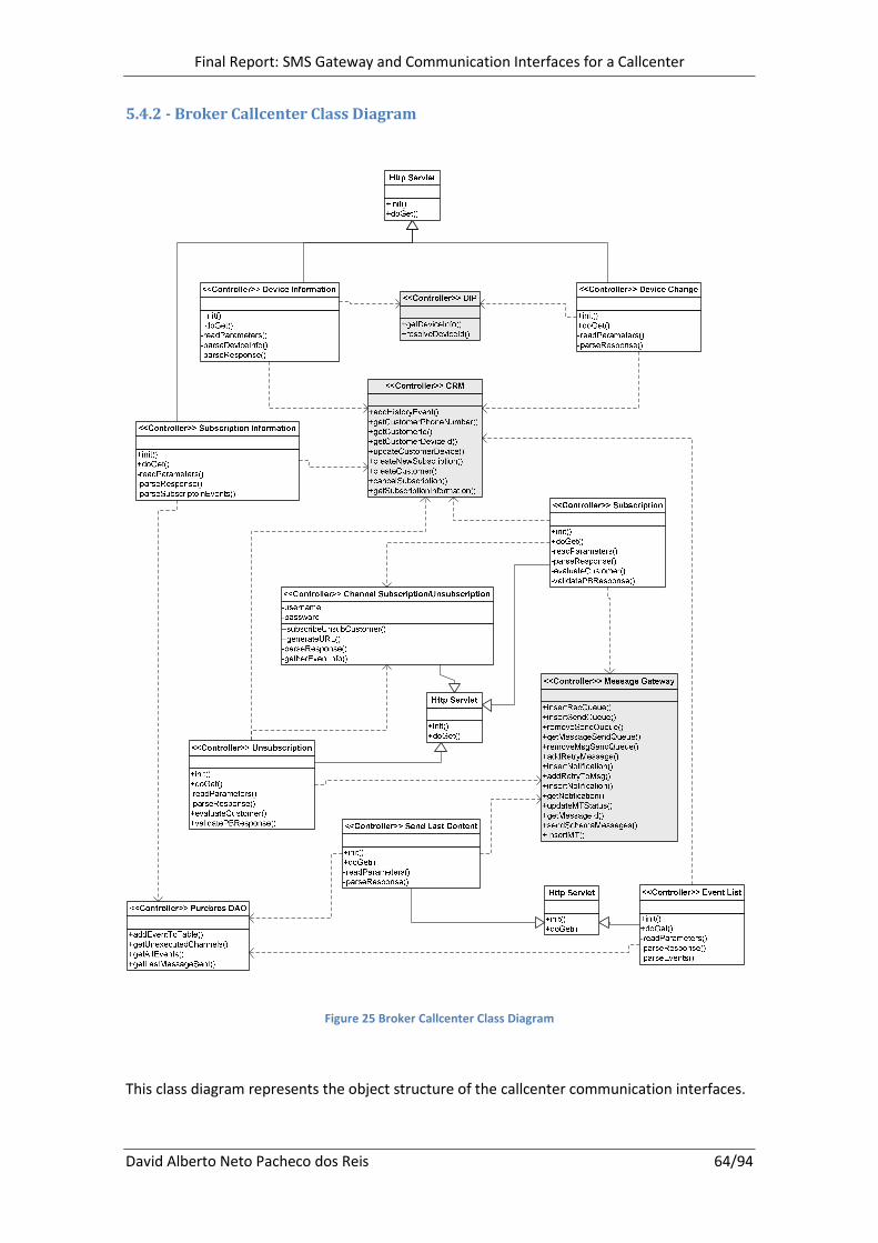
Final Report: SMS Gateway and Communication Interfaces for a Callcenter
David Alberto Neto Pacheco dos Reis 64/94
5.4.2 - Broker Callcenter Class Diagram
Figure 25 Broker Callcenter Class Diagram
This class diagram represents the object structure of the callcenter communication interfaces.

Final Report: SMS Gateway and Communication Interfaces for a Callcenter
David Alberto Neto Pacheco dos Reis 65/94
5.5 - Sequence Diagrams
The Sequence diagrams have the objective of controlling the complexity of the system. They
represent all the interactions between the different objects of the system.
The following diagrams are the result of all the previous analysis.
5.5.1 - Broker Communication Sequence Diagrams
5.5.1.1 - MO Receiving
Figure 26 Mo Receiving Sequence Diagram
This diagram represents the interactions for the MO Receiving Controller process. This process
is responsible for receiving the messages from the broker and inserting them into the
database. On this diagram is also possible to understand what information is exchanged
between all the objects.

Final Report: SMS Gateway and Communication Interfaces for a Callcenter
David Alberto Neto Pacheco dos Reis 66/94
5.5.1.2 - MT Delivery
Figure 27 MT Delivery Sequence Diagram
This diagram represents the interactions for the MT Delivery Controller process. This process is
responsible for receiving messages from the system and sending them to the broker. It also
has the responsibility to decide what to do with the message that is stored in the send queue,
either resends it or moves it to the MT table. Most of the actions on the database are done
using system APIs.
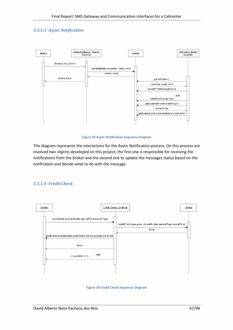
Final Report: SMS Gateway and Communication Interfaces for a Callcenter
David Alberto Neto Pacheco dos Reis 67/94
5.5.1.3 -Async Notification
Figure 28 Async Notification Sequence Diagram
This diagram represents the interactions for the Async Notification process. On this process are
involved two objects developed on this project, the first one is responsible for receiving the
notifications from the broker and the second one to update the messages status based on the
notification and decide what to do with the message.
5.5.1.4 -Credit Check
Figure 29 Credit Check Sequence Diagram

Final Report: SMS Gateway and Communication Interfaces for a Callcenter
David Alberto Neto Pacheco dos Reis 68/94
This diagram represents the interactions for the Credit Check process. This process is initiated
by the system and allows it to contact the broker using the credit check controller to grab a
ticket to bill a client.
5.5.1.5 -Billing
Figure 30 Billing Sequence Diagram
This diagram represents the interactions for the Billing process. This process is used by the
system when it has a ticket to bill a client. This interfaces then uses the ticket to call the broker
and receives a confirmation that is parsed back to the system.
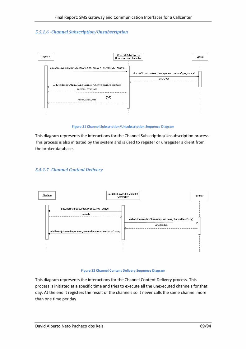
Final Report: SMS Gateway and Communication Interfaces for a Callcenter
David Alberto Neto Pacheco dos Reis 69/94
5.5.1.6 -Channel Subscription/Unsubscription
Figure 31 Channel Subscription/Unsubscription Sequence Diagram
This diagram represents the interactions for the Channel Subscription/Unsubscription process.
This process is also initiated by the system and is used to register or unregister a client from
the broker database.
5.5.1.7 -Channel Content Delivery
Figure 32 Channel Content Delivery Sequence Diagram
This diagram represents the interactions for the Channel Content Delivery process. This
process is initiated at a specific time and tries to execute all the unexecuted channels for that
day. At the end it registers the result of the channels so it never calls the same channel more
than one time per day.
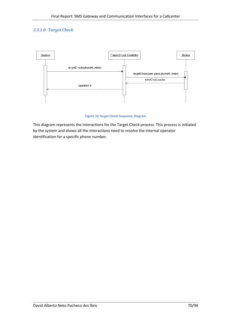
Final Report: SMS Gateway and Communication Interfaces for a Callcenter
David Alberto Neto Pacheco dos Reis 70/94
5.5.1.8 -Target Check
Figure 33 Target Check Sequence Diagram
This diagram represents the interactions for the Target Check process. This process is initiated
by the system and shows all the interactions need to resolve the internal operator
identification for a specific phone number.
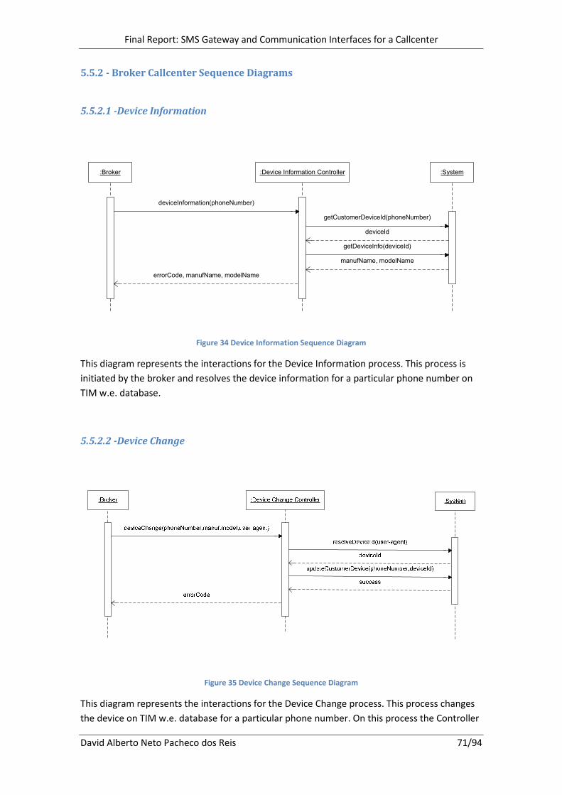
Final Report: SMS Gateway and Communication Interfaces for a Callcenter
David Alberto Neto Pacheco dos Reis 71/94
5.5.2 - Broker Callcenter Sequence Diagrams
5.5.2.1 -Device Information
:Broker :Device Information Controller :System
getCustomerDeviceId(phoneNumber)
deviceId
errorCode, manufName, modelName
deviceInformation(phoneNumber)
getDeviceInfo(deviceId)
manufName, modelName
Figure 34 Device Information Sequence Diagram
This diagram represents the interactions for the Device Information process. This process is
initiated by the broker and resolves the device information for a particular phone number on
TIM w.e. database.
5.5.2.2 -Device Change
Figure 35 Device Change Sequence Diagram
This diagram represents the interactions for the Device Change process. This process changes
the device on TIM w.e. database for a particular phone number. On this process the Controller

Final Report: SMS Gateway and Communication Interfaces for a Callcenter
David Alberto Neto Pacheco dos Reis 72/94
needs to resolve the internal device id on the database in order to update the device
information.
5.5.2.3 -Event List
Figure 36 Event List Sequence Diagram
This diagram represents the interactions for the Event List process. On this process the
controller resolves all customer events on a time frame and returns them to the broker.

Final Report: SMS Gateway and Communication Interfaces for a Callcenter
David Alberto Neto Pacheco dos Reis 73/94
5.5.2.4 - Subscription Information
Figure 37 Subscription Information Sequence Diagram
This diagram represents the interactions for the Subscription Information process. This process
is similar to the Event List with the difference that it also retrieves subscription information
from the database. All this information is converted to the broker format requisites and sent.
5.5.2.5 - Send Last Content
Figure 38 Send Last Content Sequence Diagram

Final Report: SMS Gateway and Communication Interfaces for a Callcenter
David Alberto Neto Pacheco dos Reis 74/94
This diagram represents the interactions for the Send Last Content process. On this process the
broker requests that the last content sent to a particular phone number is resent. The
controller must retrieve the message from the events table and reinserted it the send queue.
5.5.2.6 -Subscription
Figure 39 Subscription Sequence Diagram
This diagram represents the interactions for the Subscription process. This complex process
initiated by the broker subscribes a client on a TIM w.e. service. To subscribe a client the
controller needs to register the client information then it must subscribe on the broker side
first, then on TIM w.e. database and last if all succeeded it must insert on the send queue the
congratulation messages for the client.

Final Report: SMS Gateway and Communication Interfaces for a Callcenter
David Alberto Neto Pacheco dos Reis 75/94
5.5.2.7 - Unsubscription
Figure 40 Unsubscription Sequence Diagram
This diagram represents the interactions for the Unsubscription process. This process is similar
to the Subscription, the controller must unsubscribe the user from the broker side and them
from the database, after all succeeded it inserts the cancelation messages on the send queue.

Final Report: SMS Gateway and Communication Interfaces for a Callcenter
David Alberto Neto Pacheco dos Reis 76/94
5.6 - Human Resources
On this project is allocated the Brazil Project Manager, one Tester, one System and operations
architect and 2 developers.
Project Manager: Is responsible for arrangements between all the interested parts (IT,
Marketing and Broker).He is also responsible for taking decisions on the implementation of the
project, supervision, scheduling and allocation of the resources.
Tester: Is responsible for all the tests on development and production and as to ensure the
product quality.
System and operations architect: Makes the deployments to production environment.
Developers: Are responsible for designing and coding the project and future features and
maintenance.
Except the developers the remaining resources were not assigned to this project in full time
and even the developers were assigned to other tasks temporarily when it was necessary.

Final Report: SMS Gateway and Communication Interfaces for a Callcenter
David Alberto Neto Pacheco dos Reis 77/94
5.7 - Technologies and Tools
On this project was used several technologies and tools that are open source and are
standardized meaning that they offer several guaranties to its users such as retro compatibility
on future releases.
Java: In this project was used Sun java 1.5 EE which is an open source and standardized
programming language. The main characteristics of Java are: is an object oriented language, is
platform independent, has automatic memory management and runs inside a virtual machine
(JVM22
). The Sun SDK23
bundles several APIs that were used in this project being the most used
the java Servlets API (Perry, 2003).
Oracle 10g: Is a proprietary database engine that is very scalable and provides state of the art
performance. This database engine is used on this project for some DML using the SQL
Developer tool from Oracle (Abramson & Abbey, 2004).
Apache Tomcat: Is an Application Server that provides a Servlet Container service. Tomcat
offers high performance when compared to its competitors and is free. On this project is used
Tomcat 5.5. (Chopra, Bakore, Eaves, Galbraith, Li, & Wiggers, 2004)
Maven 2: Is a free software that eases java project management and building. This tool makes
use of a POM 24
which is basically an XML 25
file that can be edited manually. It is used on this
project to assist the compilation and build of the project (Massol & O'Brien, 2005).
SVN: SubVersioN is a free version control system that is used to control file changes. It is used
to maintain current and historical versions of files. On this project it is used to maintain all
current and historical source code changes and to enable simultaneous development on the
same project by different developers.
22
JVM: Java Virtual Machine 23
SDK: Software Development Kit 24
POM: Project Object Model 25
XML: eXtensible Markup Language

Final Report: SMS Gateway and Communication Interfaces for a Callcenter
David Alberto Neto Pacheco dos Reis 78/94
5.8 - Database Tables
The image below shows the main tables used by the several modules of the system. None of
these tables was created for this project in particular. But it is interesting to give an image of
the structure.
These tables exist on the production and reporting environment with a few differences mainly
at indexes level, because they have different objectives.
Figure 41. Main Database Used Tables
A description of the tables:
Receive Queue: Is where the messages that arrive to the platform are placed for later
resolution by the service that is responsible for them.
Send Queue: Here is where the output messages are placed, and will be read and sent by the
service that is responsible for sending them.
MT Table: Is where all the messages that have been sent are stored.
Notification: The notifications that come from the broker are stored on this table for later
resolution.
Subscription: Here is stored all the subscription information of all customers.
Customer: Is where is stored the customers information.

Final Report: SMS Gateway and Communication Interfaces for a Callcenter
David Alberto Neto Pacheco dos Reis 79/94
Event: Here are stored all events that are needed by a specific service, as the case of the
Callcenter, that needs more information that is not available or easily accessible on other
tables.
History: Here is stored all the common events that occurs on the platform. This table is
platform specific because it only maintains information generated by common interfaces.

Final Report: SMS Gateway and Communication Interfaces for a Callcenter
David Alberto Neto Pacheco dos Reis 80/94
5.9 - Modules
Here are shown all the modules that are present and used on this project. The grey modules
are existing modules that are used by the developed modules of this project but are out of this
project domain. The light blue are the modules developed on this project. After the next
image is a short description of all these modules.
Xconn IN
Callcenter
Notification Servlet
Notification Monitor
VAF
Purebros API
MG
Xconn OUT
DIP
CRM
Figure 42. Project Modules
CRM: This module is composed by an API that allows subscriptions and customer operations. It
encapsulates the database access for this type of operations.
MG (Message Gateway): This module is composed by an API that allows message operations
and also encapsulates all the database access. It is also composed by a monitor that reads the
messages from the send table and calls the class that resolves them.
DIP: This module is composed by an API that allows device resolution and information
operations. It encapsulates the database access for this type of information.
VAF: This module is not used in this project but is the main user of all the components of this
project. This is the module that is responsible for message resolution and is responsible for
reading the incoming messages from the receive queue and generate the output messages to
the send queue.

Final Report: SMS Gateway and Communication Interfaces for a Callcenter
David Alberto Neto Pacheco dos Reis 81/94
Xconn OUT: This module is known on this project by MT Delivery interface and is responsible
for sending the messages to the broker, using the communication format agreed.
Xconn IN: This module is know on this project by MO Receiving interface and is responsible for
receiving the messages from the broker and converting them to the platform internal format.
Notification Servlet: This module receives the message notifications from the broker and
stores them on a table.
Notification Monitor: The monitor reads the pending notifications and updates the messages
information.
Purebros API: The Purebros API is composed by several interfaces that implement useful
functionalities to the broker. These functionalities can be used by any application on the
system.
Callcenter: Is a composition of all the Callcenter interfaces that are available to the broker.

Final Report: SMS Gateway and Communication Interfaces for a Callcenter
David Alberto Neto Pacheco dos Reis 82/94
5.10 - Deployment and Architecture
Since the beginning of this project the deployment environment was already decided. The
image below represents all TIM w.e. internal structure and the possible broker/carriers
communication architecture. This image also displays the deployment diagram of the
components used on this project.
<<Broker>>
Firewall
Server
Load
Balancer
Server
<<Mobile Operator>> <<Mobile Operator>> <<Mobile Operator>> <<Mobile Operator>>
Communication/
Billing InterfacesCallcenter UI
<<Drum>>
<<Webservice>>
<<Database>>
Production
<<Database>>
ReportingXconn OUT
Callcenter
TCP/IP HTTPTIM w.e. Internal Structure
HTTP
JDBC
HTTP
Replicated
Xconn IN / Notif
JDBC
HTTP
JDBC
HTTP
Figure 43. Deployment and Architecture Diagram

Final Report: SMS Gateway and Communication Interfaces for a Callcenter
David Alberto Neto Pacheco dos Reis 83/94
5.10.1 - Broker and Mobile Carriers
The broker is interconnected with several mobile carriers. The main object of a broker is to
potentiate and simplify the integration of its clients, which using a single connection can hit all
the mobile carriers clients. This eases the integration time and enables its clients to expand to
new markets faster.
5.10.2 - TIM w.e. Internal Structure
The internal structure of TIM w.e. is composed by many components next is a short
description of them that will help understand the big picture of the platform and its main
components:
Firewall: Is the frontline of the entire platform and has the responsibility of only enabling
trusted entities to access the internal services. It also controls and monitors all traffic
exchanges.
Load Balancer: Since TIM w.e. has several replicated services the load balancer has the
objective of distributing the requests by these services based on their load capacity.
Drum: Is a Java Application that is used as a container to other java classes that run inside it.
The drum decides and controls all the launch and execution of those classes and provides error
control mechanisms.
Tomcat Application Server (WebService): Tomcat is a free Application Server distributed by
Apache that is able to execute java servlets. This Application Server is responsible for
containing all the servlets developed on this project. The Applications Servers are also
replicated on several servers to give redundancy to the system.
Production Database: This Oracle database contains all the production information that is
used by all the system. Its schema is designed to give maximum performance on the most used
transactions.
Report Database: This database contains all the information gathered by the Production
Database. It also contains more refined data that was extracted from the raw data on
Production. Its schema was design to be a data warehouse, so it delivers better performance
for reporting tasks. An important fact is that the reporting database is not synchronized on real
time with the production database, it as a small delay that corresponds to the time taken to
the data migration from one to another.

Final Report: SMS Gateway and Communication Interfaces for a Callcenter
David Alberto Neto Pacheco dos Reis 84/94
5.11 - Tests
The objective of the software tests developed by the QA tester is to detect possible errors on
the application and to ensure the application respects the context in which it is intended to
operate.
These tests are done when a new functionality is implemented. This is possible because all the
functionalities are independent and because the team as a member for this specific task.
The tests where executed tests on two distinct environments, development and production.
5.11.1 - Development
The development tests are the first tests done by the QA tester. The developer deploys the
application to a development server and requests the tests.
These tests are done on the internal platform with simulated requests to the system. The
objective is to stimulate the system and find possible integration errors, bugs or bad
implementations. These tests are done until no problem is found.
The tester applies black and white tests to all the application.
5.11.1.1 - Black Box Tests
These tests aim to test the functionality of the application according to its requirements. The
tester inputs data and sees the output from the test object. He then validates if the output is
the expected output. The tester applies equivalence partitioning tests and boundary values
analysis.
5.11.1.2 - White Box Tests
These tests aim to test the internal data structure, code and algorithms. On this tests the
tester tests the functional points of the application and ensures that all the possible lines of
code are executed at least one time and have the expected output. These tests are
complemented with the black box tests.

Final Report: SMS Gateway and Communication Interfaces for a Callcenter
David Alberto Neto Pacheco dos Reis 85/94
5.11.2 - Production
The production tests are done after the application passes the QA tests. The developer then
requests deploy of the application to production environment.
These tests are done live with the broker, with real requests from the broker and on
production database. This is the final validation step before the system is accepted as fully
compliant with the broker requisites. The tests applied on this phase are of broker
responsibility.
5.12 - Maintenance and Improvements
After the implementation minor alterations were done at the Callcenter, mostly alterations to
the response format sent to the broker. Other alterations were done on the service mappings
but these were easily done at properties files, no coding needed.
There were also a few performance issues on the platform, the module that manages the
messages was not being able to dispatch all the messages and the messages started to form a
big queue. The cause of this problem was the enormous number of messages that Brazil
service started generating. The problem was solved increasing the number of threads to send
the messages and with hardware updates on the servers.

Final Report: SMS Gateway and Communication Interfaces for a Callcenter
David Alberto Neto Pacheco dos Reis 86/94
6 - Conclusions
All the development of this project as run as planned and the implementation followed the
predicted timeframe.
This project is now fully operational and being used by TIM w.e. to serve more than one million
clients. The communication interfaces sends more than one million messages per day and
receives more than fifty thousand from all the four mobile carriers they are connecting.
The Callcenter is being used on Brazil by the broker and mobile carriers to resolve problems
reported by its clients.
Since the project had a software quality tester, it greatly helped the entire project outcome
because he assured all the requisites were fully compliant with the broker and with the project
specifications.
Even knowing that the entire project has run as planned there are some aspects that could
have been improved. Because this project is locked to an existing platform it limited the design
options because there was already a predefined design and implementation model to follow.
This platform has also some bad aspects and was not thought to support all the possible
services that it is now offering, this means that some implementations must grow outside the
platform in order to provide all the requirements, which was the case of the Callcenter.
There was a design decision that was taken that on my opinion was wrong. It was decided to
follow the existing logic; this is separating the broker connection logic from the platform logic.
On my opinion the common logics should have been integrated on one module that offered all
the integrated broker and platform logic since most operations need several actions on the
broker and on the platform. The objective was to encapsulate these regular operations and
use them in the several products instead of create one logic for each product when it was not
needed.
There were some performance issues also that were promptly solved, initially adding more
threads to the pool of the messages and later with hardware updates to the servers. This
problem could have been minimized if the monitor that calls the MT deliver interface to send
the messages calls it with several messages instead only one at the time. Again this is a
limitation of the platform that could be changed to enable better performances.
During this project the human resources allocated were also divided on demand between
other developments such as Webspots, new SMS flows and Wapsites.

Final Report: SMS Gateway and Communication Interfaces for a Callcenter
David Alberto Neto Pacheco dos Reis 87/94
6.1 - Future work
All the interfaces that were implemented were the required for the service to be fully
complaint by the broker and mobile carriers requirements.
But not all the possible interfaces that the broker provides were implemented, there still exists
more communication and callcenter interfaces to implement. If fully necessary or if they come
to be useful there will be future works on this project.
A very feasible future work would be the creation of a package that integrates the common
operations that need actions from the broker and from the platform with the objective of
standardization of all the common operations.
It is also expected that TIM w.e. platform evolves to new technologies and this will influence
all the way this project is implemented. There are already plans to create all the modules
using EJB26
technology.
The new developments will also change the database structure, but this will have small impact
on this project because all the database access is encapsulated by other modules.
6.2 - Personal Experience
The work developed during the last nine months on this project in particular and on the
several products of TIM w.e. have teach me new technologies, tools and works methods that I
ignored. Being on TIM w.e. have also proven to be a constant challenge since it is a very young
company that is growing fast and has lots of new challenges and opportunities for learning
new products and technologies.
Right now I have moved from the Brazil operation development team to a new Business
Intelligence team, I am now learning data warehouse concepts and Microsoft Business
Intelligence tools.
The environment in TIM w.e. is fantastic and my colleagues were always very helpful. The
company is composed mostly by young people to have an idea the company average age is
around 26 years.
26
EJB: Enterprise Java Beans

Final Report: SMS Gateway and Communication Interfaces for a Callcenter
David Alberto Neto Pacheco dos Reis 88/94
Extensive Abstract in Portuguese
Introdução
Depois do boom da internet estamos actualmente a assistir a um novo boom no mercado dos
serviços móveis. A empresa onde se desenrola este projecto a TIM w.e. é uma empresa
portuguesa que trabalha no mercado do entretenimento para telemóveis.
A TIM w.e. nasceu em 2002 e inicialmente dedicava-se á criação e venda de conteúdos de
telemóveis para operadores nacionais. Hoje em dia a TIM w.e. já opera em mais de 56 países,
têm 19 escritórios no estrangeiro e mais de 260 empregados.
Actualmente a TIM w.e. encontra-se ligada a mais de dois terços dos operadores mundiais e
está a vender os seus produtos em quase todo o mundo, isto tudo para uma empresa que têm
apenas seis anos de existência.
O projecto efectuado durante os últimos meses corresponde á criação da ligação com um
broker de telecomunicações no Brasil. Esta ligação será composta pelas interfaces de
comunicação básicas e as interfaces de comunicação para o Callcenter.
As interfaces de comunicação fornecem serviços de gestão de utilizadores e troca de
mensagens com o broker. As interfaces do Callcenter fornecem informações sobre os eventos
dos utilizadores na plataforma da TIM w.e. e também permitem aos operadores do Callcenter
aplicar operações sobre os utilizadores.
Este projecto têm elevada importância pois permitiu á TIM w.e. passar a fornecer os seus
serviços a quatro grandes operadores moveis no Brasil (TIM, Claro, Brasil Telecom e OI).
Departamento de Informática
Devido ao número já significativo de empregados e às diferentes áreas técnicas que trabalham
na TIM w.e. esta encontra-se dividida por departamentos. Existem quatro grandes
departamentos, Back Office que está responsável pela resolução de problemas reportados
pelos clientes. PROD onde se produzem alguns tipos de conteúdos para venda e imagens e
vídeos para campanhas publicitárias. O departamento de Marketing está responsável pela
tomada de decisão sobre as campanhas e contacto com novos parceiros de negócio. E
finalmente o departamento de informática que é responsável por toda a plataforma
informática da empresa desde criação das ligações com operadores e brokers, á criação de
novos produtos web, wap e sms, analise de problemas, gestão da rede, monitorização e
outros.

Final Report: SMS Gateway and Communication Interfaces for a Callcenter
David Alberto Neto Pacheco dos Reis 89/94
O departamento de informática encontra-se divido em vários grupos e cada uma deles pode
estar associado a um projecto, pais ou parte do mundo. Este projecto em particular desenrola-
se no grupo de operation developers associados á zona do Brasil, esta equipa é composta por
um gestor de projecto, um tester, um arquitecto de sistemas e quatro programadores.
Trabalho Inicial
A área de operation development é referente às equipas trabalham especificamente para os
países e para os seus produtos. Um operation developer trabalha com diversos produtos, entre
os mais importantes estão os webspots, criação de novos países, serviços e clubes na
plataforma, wap sites, e ligações a operadores e brokers.
O conhecimento dos diversos produtos utilizados permite entender como este funcionam
sobre a plataforma da TIM w.e. isto é bastante útil em desenvolvimentos futuros pois permite
tomar as melhores opções de implementação, como foi o caso deste estágio em que a sua
parte inicial foi aplicada á aprendizagem e desenvolvimento nos vários produtos.
Objectivo do Projecto e Metodologias
O objectivo deste projecto foi criar varias interfaces de comunicação que permitiram á
plataforma da TIM w.e. comunicar com o broker e através deste atingir os clientes de quatro
operadores móveis no Brasil.
O projecto está dividido em dois objectivos: a criação das interfaces de troca de mensagens
com o broker e as interfaces de comunicação para o Callcenter. As interfaces de troca de
mensagens são constituídas por serviços de recepção e envio de mensagens, cobrança e
outros. Estas interfaces servem de elo de comunicação e compatibilização entre a plataforma
do broker e a TIM w.e.. O Callcenter será composto por varias interfaces que permitem ao
broker visualizar vários tipos de eventos dos seus clientes e efectuar operações sobre estes.
Este projecto foi desenvolvido seguindo o modelo em cascata. Com uma pequena nuance que
todo a analise e desenho das interfaces de troca de mensagens e do Callcenter são feitas na
mesma fase e a implementação, testes e manutenção estão separadas entre elas, como se
pode concluir no anexo 2.

Final Report: SMS Gateway and Communication Interfaces for a Callcenter
David Alberto Neto Pacheco dos Reis 90/94
O Projecto
Como trabalho de projecto foi descrito todos os requisitos dos intervenientes, alguns
pressupostos assumidos inicialmente, todo o estudo de engenharia de software desde casos
de uso, diagramas de actividade, de classes, de sequência e de arquitectura do sistema. Ainda
foram descritos os vários módulos envolvidos neste projecto, as tecnologias utilizadas,
esquemas da base de dados e os tipos de testes levados a cabo pela equipa de testes.
Ao todo são oito interfaces no contexto de troca de mensagens e sete para o Callcenter. As
oito interfaces de troca de mensagens são: MO Receiving (recepção de mensagens), MT
Delivery (envio de mensagens), Async Notification (recepção e tratamento de notificações),
Credit Check (verificação do credito de cliente), Billing (cobrança de cliente), Channel
Subscription/Unsubscription (registar ou cancelar cliente no broker), Channel Content Delivery
(efectuar broadcast de uma mensagem para um canal ou serviço) e o Target Check (validar
operador do cliente). As sete interfaces do Callcenter são: Device Information (obter
dispositivo do cliente), Device Change (alterar dispositivo do cliente), Event List (obter todos os
eventos do cliente), Subscription Information (obter todos os eventos de subscrição do
cliente), Send Last Content (reenviar conteúdo ao cliente), Subscription (registar cliente num
serviço) e Unsubscription (cancelar cliente de um serviço).
Na análise de requisitos do sistema existiram vários factores que foram levados em conta, o
primeiro foi os requisitos do broker, que exige que um certo número de interfaces e serviços
sejam implementados e fornecidos pela TIM w.e., para que seja possível iniciar a actividade
comercial por estas interfaces. O segundo requisito têm a ver principalmente com as interfaces
de troca de mensagens com o broker, estas interfaces foram implementadas seguindo o
modelo de integração de novas ligações na plataforma já existente, de modo a que todos os
serviços que funcionam nesta continuam a ser compatíveis e possam utilizar as novas
interfaces. O facto de existir um modelo de integração levou a que tenha sido decidido á priori
como as interfaces iriam ser implementadas pois isto influencia directamente todo o desenho
do sistema.
Todo o desenho do sistema está descrito pormenorizadamente no relatório em inglês do
projecto, desde os diagramas de caso de uso, descrição de casos de uso, diagramas de
actividade, classes e sequência.
Neste projecto estiveram envolvidos cinco elementos da equipa de operation development do
Brasil. A equipa deste projecto foi constituída por um gestor de projecto, um tester, um
arquitecto de sistemas e dois programadores, exceptuando os programadores os restantes
recursos não estão alocados a este projecto a tempo inteiro, e os programadores sempre que
foi necessário efectuar outros desenvolvimento foram alocados temporariamente a outras
tarefas.
Neste projecto foi utilizado varias tecnologias e ferramentas. Como linguagem de codificação
foi utilizado java e em especial servlets java. Foi ainda utilizado algum Oracle SQL para acessos

Final Report: SMS Gateway and Communication Interfaces for a Callcenter
David Alberto Neto Pacheco dos Reis 91/94
à base de dados. Como ferramentas foi utilizado o Apache Tomcat como servidor aplicacional,
maven 2 para a gestão do projecto e SVN para controlo de versões dos ficheiros.
A fase de testes de desenvolvimento e integração foi efectuada pelo tester da equipa. Nesta
fase o tester tem maior influência nos testes de desenvolvimento onde são aplicados testes de
caixa negra e de caixa branca. Após a aplicação passar estes testes com sucesso e garantindo
todos os requisitos é colocada em produção aqui será o broker que irá validar o correcto
funcionamento das interfaces.
Após a implementação do sistema existiram apenas pequenas correcções pontuais que eram
espectáveis.
Conclusões
Todo o desenvolvimento correu como esperado e dentro dos prazos estabelecidos.
Actualmente o serviço fornece mais de um milhão de clientes, recebe mais de cinquenta mil
mensagens por dia e envia mais de um milhão.
Devido ao facto do projecto ter alocado recursos em áreas bastante especificas e com
objectivos definidos permitiu no geral melhorar todo o processo de desenvolvimento. O tester
conseguiu assegurar que quando o broker efectuava os testes em produção a maioria das
interfaces era aprovada na primeira tentativa.
Apesar de tudo ter corrido como esperado seria possível melhorar o sistema actual pois
actualmente este tipo de integrações estão muito limitada á plataforma em que assenta e esta
nem sempre se adapta da melhor maneira as necessidades de cada broker ou operador. Uma
das soluções poderá passar por num futuro próximo adaptar toda a plataforma e os vários
módulos á tecnologia EJB, isto iria permitir que cada módulo tivesse mais liberdade em relação
á plataforma.
Este projecto e o trabalho nos vários produtos da TIM w.e. ensinaram-me novas tecnologias,
ferramentas e métodos de trabalho que serão bastante úteis para a minha carreira. Estar
numa empresa que está em constante crescimento oferece bastantes desafios e
oportunidades para aprender e estar á frente no desenvolvimento de novos produtos e
serviços.

Final Report: SMS Gateway and Communication Interfaces for a Callcenter
David Alberto Neto Pacheco dos Reis 92/94
Bibliography
Abramson, I., & Abbey, M. (2004). Oracle Database 10g: A Beginner's Guide. Osborne ORACLE
Press Series.
Chopra, V., Bakore, A., Eaves, J., Galbraith, B., Li, S., & Wiggers, C. (2004). Professional Apache
Tomcat 5. Wrox.
Massol, V., & O'Brien, T. (2005). Maven: A Developer's Notebook. O'Reilly.
Nunes, M., & O'Neill, H. (2004). Fundamental de UML 4ª Edição. FCA.
Perry, B. (2003). Java Servlet & JSP Cookbook. O'Reilly.
Robinson, M., & Finkelstein, E. (2004). Jakarta Struts for Dummies. For Dummies.

Final Report: SMS Gateway and Communication Interfaces for a Callcenter
David Alberto Neto Pacheco dos Reis 93/94
Annex 1

Final Report: SMS Gateway and Communication Interfaces for a Callcenter
David Alberto Neto Pacheco dos Reis 94/94
Annex 2


![Gateway Documentation - SMS Service Oracle FLEXCUBE ...€¦ · Gateway Documentation - SMS Service Oracle FLEXCUBE Universal Banking Release FCUBS_12.0.3.0.0 [April] [2014]](https://static.fdocuments.in/doc/165x107/5fce6d7888c20b62135e0597/gateway-documentation-sms-service-oracle-flexcube-gateway-documentation-.jpg)


![[Jurnal] Sms-Gateway [Eng]](https://static.fdocuments.in/doc/165x107/55328f8d55034626518b4638/jurnal-sms-gateway-eng.jpg)