
SMR Evaluation Kit User Manual · - Experience and Reliability in Radar Technology Experience and...
15
Experience and Reliability in Radar Technology- www.InnoSenT.de SMR Evaluation Kit User Manual
Transcript of SMR Evaluation Kit User Manual · - Experience and Reliability in Radar Technology Experience and...

Experience and Reliability in Radar Technology- www.InnoSenT.de
SMR Evaluation KitUser Manual

Experience and Reliability in Radar Technology - www.InnoSenT.dewww.InnoSenT.de - Experience and Reliability in Radar Technology
SMR Evaluation Kit user manual
2 3
Overview
The Evaluation Kit “EVALKIT SMR-334” is a programmable compact radar system with
a focus on creating a friendly and easy-to-use FMCW radar platform. It comes with a
custom and open firmware that provides beginners with an easy way to experience
radar sensors in their application and take a look into the signal processing with our
detailed examples.
The SMR-Eval Kit is built around the SMR sensor family and comes equipped with
our flagship module SMR-334. The underlying STM32F401RE Nucleo Board from
ST provides the necessary processing power and interface to the IDE and GUI. The
kit comes with all necessary hardware, software and documentation to quickly start
evaluating innovative radar technology.
Features
• Supports Doppler and FMCW radar principle
• VCO controlled with 16-bit DAC on the SMR interface module
• Stereo receiver
• 12bit data acquisition
• Configurable Doppler frequency and FMCW bandwidth
• Frequency auto-calibration for compliance with government regulations
• Simple GUI to visualize receive signals
• ADC raw data and FFT display
• Configurable radar parameters for advanced users
- Bandwidth
- ADC sampling rate
- Frequency auto-calibration enable
- Etc.
• Full SMR antenna module control
• System power and communication via a single USB interface
• Source code with detailed comments giving users full control to the Evaluation
Kit
1. Introduction
Content
Introduction 3
Installation 4
Brief Introduction to Radar Principles 6
Getting Started 11
Radar configurable parameters 19
Data Transmission 20
Signal Processing 22
Frequency Auto-Calibration 22
Complete Application Diagram 24
Hardware 25
References 28
History 28

Experience and Reliability in Radar Technology - www.InnoSenT.dewww.InnoSenT.de - Experience and Reliability in Radar Technology
SMR Evaluati on Kit user manual
4 5
Hardware Installation
The SMR-EvalKit packet consists of:
• SMR antenna module
• STM32F401RE-Nucleoboard
• Mini USB cable
• Download link on the InnoSenT Homepage: Project fi les with
Source code, GUI, User Manual, Quickstart Software, SMR Data Sheet)
2. Installation In order to have a proper hardware installation, please follow the instructions below:
• The SMR Evaluation Kit comes preassembled, however it is also possible to
disassemble the two boards.
• When the two boards are separated and need to be assembled, connect them as
in the following picture. Note: before connecting the two boards please make sure the
power supply to the STM32F401RE board (via USB cable) is disconnected in order to
prevent any damage to the system due to wrong connection and the connection should
be checked again before applying the power supply.
• Jumpers on the microcontroller board should be left unchanged.
Figure 1: SMR Antenna module Figure 2: STM32F401RE-Nucleoboard
Figure 3: SMR-board and STM32 board connection
Software Installation
Please refer to the SMR Evaluation Kit quick start guide for instructions about the software installation.

Experience and Reliability in Radar Technology - www.InnoSenT.dewww.InnoSenT.de - Experience and Reliability in Radar Technology
SMR Evaluati on Kit user manual
6 7
3. Brief Introduction to Radar PrinciplesDoppler Principle
Basis elementsThe CW-Doppler radar is the simplest kind of Radar, but most effective for detecting motion
and measuring speed. It utilizes the Doppler Effect, an effect which applies to all sorts of
wave generators and says the following:
Wave fronts, transmitted by a wave generator (sound, microwaves, light etc.) hit a moving
target. Depending on the direction of the motion of this object, the wave fronts are either
“compressed” or “stretched”, which fi nally results in a shift in frequency. The received signal
is mixed with the unchanged transmit signal in the receiver (called “homodyne” mixing),
which results in a sinusoidal intermediate frequency (IF). It doesn’t matter whether the
sensor moves relatively to the object or the object moves relatively to the sensor.
As a matter of fact, only the radial component of the velocity vector can be detected. The
mathematical formula looks as follows:
fD Doppler- or differential frequency
f0 Transmit frequency of the radar
v velocity of the moving object
C0 Speed of light
Angle between the actual direction of motion and the connecting line
sensor-object
Selecting 24GHz as transmit frequency, the following rule of thumb applies:
With this simple equation the expected Doppler frequency can easily be calculated and the
parameters of the IF-fi lter and amplifi er can be defi ned.
For instance it is not practical to design the upper frequency limit of the signal conditioning
part of a unit detecting human beings much higher than 300Hz, since this corresponds to a
speed of 6.8 km/h of a (pretty fast) pedestrian. On the other hand, when using radar sensors
to check the speed of cars for example on a German motorway, the amplifi er needs to have
an upper frequency limit of at least 10 kHz corresponding to 220 km/h.
α
As a summary the speed of an object can be evaluated by measuring the Doppler
frequency (in an analog system by counting the zero crossings or in digital system by
frequency analysis with FFT), while considering the angle of the motion vector.
Please note:
In the very rare case of a perfect circular motion of the object around the sensor, the
angle would be 90o, which causes the cosine and therefore the Doppler frequency
to drop to zero. This specifi c motion won’t be detected by this type of radar. However
this object would have to move along this circle with absolute perfection, which is
highly unlikely for a real life object.
Identifi cation of direction of motion
Radar sensors with dual IF output can provide information about the direction of motion (leaving or approaching) simply by utilizing two mixer circuits, which are spaced by a quarter wavelength, called an I(n phase)/Q(uadrature phase) mixer.
This information is useful for example in door opener applications, where the door should open only when a person approaches it.
For detailed information on the radar basics, see Application_Note I-IV on the InnoSenT homepage.
Example
The calculation of the parameters of the implemented CW-Doppler example is shown below:
α
speed of light C0 299792458 m/s
CW-Frequency F depending on FREQ_START Hz
Example: 24.000 GHz
sampling period Ta 0.0004 s
400 µs
buffer length (number of samples) N 128
sampling time Tsample 0.0512 s
51.2 ms
velocity resolution Vmin 0.122 m/s
0.44 km/h
low pass fi lter (theoretical) LP 1250 Hz
low pass fi lter (current hardware) 915 Hz
high pass fi lter (theoretical) HP 19.53 Hz
high pass fi lter (current hardware) 20 Hz

Experience and Reliability in Radar Technology - www.InnoSenT.dewww.InnoSenT.de - Experience and Reliability in Radar Technology
SMR Evaluation Kit user manual
8 9
4. FMCW PrincipleBasis elements
The FMCW-(Frequency-Modulated-Continuous-Wave) radar is a common approach to de-tect stationary objects.
Unlike a Pulse Radar the FMCW sensor emits a continuous wave changing the frequency linearly over time. Due to the propagation delay the received signal shows a slightly dif-ferent frequency compared to the presently generated signal leading to a beat frequency in the receiver, which is proportional to the travelling time.
The following equation describes the relation in case of a sawtooth-modulation:
fD differential frequency Δf frequency deviation (bandwidth) T sawtooth prepetition time period R distance of a reflecting object C0 speed of light
For the 24GHz-ISM-Band the modulation bandwidth is limited by regulation to 250MHz at maximum. In consequence the range resolution is limited to 60cm as a theoretical value. In practice ranging for distances greater than 2m is possible with simple data pro-cessing. Closer ranges are possible using more complex algorithms.
For more detailed information on the radar basics, see Application_Note I-IV on the Inno-SenT homepage.

Experience and Reliability in Radar Technology - www.InnoSenT.dewww.InnoSenT.de - Experience and Reliability in Radar Technology
SMR Evaluation Kit user manual
10 11
Crosstalk 5. Getting Started
speed of light C0 299792458 m/s
bandwidth B depending on FREQ_START and FREQ_STOP
Hz
Example: 250 MHz
sampling period Ta 0.0004 s
400 µs
puffer length (number of samples) N 128
sampling time (modulation time) Tsample 0.0512 s
51.2 ms
range resolution Rmin 0.60 m
maximum range (theoretical) Rmax 37.8 m
low pass filter (theoretical) LP 1250 Hz
low pass filter (current hardware) 915 Hz
high pass filter (theoretical) HP 19.53 Hz
high pass filter (current hardware) 20 Hz
FREQ_START = 24.000GHz
FREQ_STOP = 24.250GHz
A typical problem of FMCW radar is the crosstalk between transmitter and receiver
due to non-ideal isolation between them. The crosstalk effect causes blind zone
approximately 3m from sensor at 24GHz. This blind zone can be reduced by applying
Highpass filtering, but it cannot be eliminated entirely.
Example
The calculation of the parameters of the implemented FMCW-modulation example is
shown below:
Receive Signals Visualization
The SMR-EvalKit is a plug-and-play device. The system will boot the previously
uploaded firmware as soon as it receives power via its USB port and the IF signals can
be visualized using the SMR EvalKit GUI.
To visualize receive signals:
• open the SMR EvalKit GUI
• select corresponding Comport of SMR EvalKit
• Click Connect/Disconnect button to connect or disconnect to SMR EvalKit Comport
In the GUI, the upper graph shows the raw receive signals on I- and Q-channel. The
magnitudes are scaled in digit values. The bottom graph shows the corresponding FFT
of raw receive signals and is displayed logarithmic (dB).
Select ComportComport Connect/Disconnect
Current modulation
“Crosstalk effect”
Object at FFT-bins 9-11
Note: When starting SMR-Evalkit, it may take a few seconds to perform initial frequency calibration and there is no data being transmitted to the PC during this time. It might take a few moments until a signal is displayed in the GUI.

Experience and Reliability in Radar Technology - www.InnoSenT.dewww.InnoSenT.de - Experience and Reliability in Radar Technology
SMR Evaluati on Kit user manual
12 13
Radar Setting Modifi cation
By modifying and uploading the source code onto the microcontroller board, the radar
settings can be changed to different confi gurations. The following instructions show the
procedure for doing this:
a) Create a workspace folder for the project e.g: “C:\SMR_EvaluationKit_WS”
b) Copy the SMR EvalKit fi rmware project folder into the workspace
c) Run SW4STM32 software and select the created workspace folder
d) Go to workbench
a) Import the project containing the source code into the workspace. In the Project
Explorer tab -> Right Click -> Import -> General -> Existing Projects into Workspace -> Select
root directory -> Brower -> “select directory where the source code project located” -> OK
-> Finish
b) Expand the project and open the fi le “CONFIG.h” in “Inc” folder
Experience and Reliability in Radar Technology - www.InnoSenT.dewww.InnoSenT.de - Experience and Reliability in Radar Technology
SMR Evaluati on Kit user manual
14 15
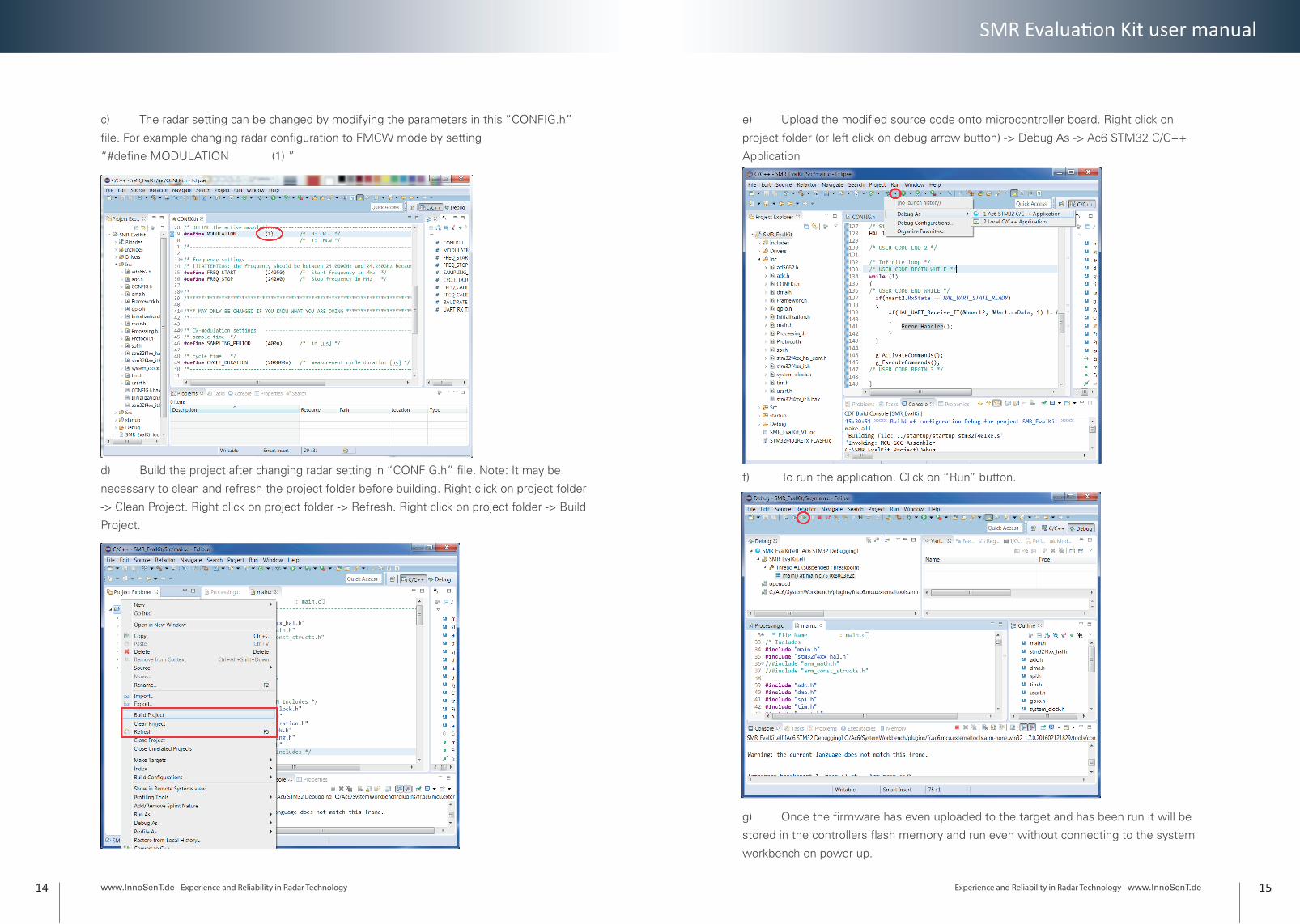
c) The radar setting can be changed by modifying the parameters in this “CONFIG.h”
fi le. For example changing radar confi guration to FMCW mode by setting
“#defi ne MODULATION (1) ”
d) Build the project after changing radar setting in “CONFIG.h” fi le. Note: It may be
necessary to clean and refresh the project folder before building. Right click on project folder
-> Clean Project. Right click on project folder -> Refresh. Right click on project folder -> Build
Project.
e) Upload the modifi ed source code onto microcontroller board. Right click on
project folder (or left click on debug arrow button) -> Debug As -> Ac6 STM32 C/C++
Application
f) To run the application. Click on “Run” button.
g) Once the fi rmware has even uploaded to the target and has been run it will be
stored in the controllers fl ash memory and run even without connecting to the system
workbench on power up.

Experience and Reliability in Radar Technology - www.InnoSenT.dewww.InnoSenT.de - Experience and Reliability in Radar Technology
SMR Evaluati on Kit user manual
16 17
SMR-EvalKit Pin layout and software components
a) STM32Cubemx
The SMR-EvalKit pin layout as well as software components confi gurations can be viewed
using STM32Cubemx. To do this, open STM32Cubemx software and load the fi le “SMR_
EvalKit.ioc” in the SMR_EvalKit_Project folder.
STM32F401RE Pin map (https://developer.mbed.org/platforms/ST-Nucleo-F401RE/)
b) SMR-EvalKit Pin Confi guration
Name Pin map
GPIO Description Note
Vcc_EN PB10 Output Power supply of SMR board High-active
SMR_Vcc_EN PB5 Output Power supply SMR radar module High-active
SMR_Tx_out_EN PB4 Output Transmit signal amplifi er High-active
Vcc_div_EN PC7 Output Transmit signal down-conversion High-active
Tx_Div_out PA0 Input Down-converted transmit signal Square wave signal
Test_pin_0 PC8 Output For testing purpose high-active
Test_pin_1 PC6 Output For testing purpose high-active
RCC_OSC_IN PH0 n/a External clock input n/a
RCC_OSC_OUT PH1 n/a External clock output n/a
I_ADC PA4 Input Receive I-Channel signal Analog
Q_ADC PA1 Input Receive Q-Channel signal Analog
SPI1_CS PB6 Output SPI Chip select Low-active
SPI1_CLK PA5 Output SPI Communication clock high-active
SPI1_MOSI PA7 Output SPI Transmission of data to SMR board
high-active
SPI1_MISO PA6 Input SPI Reception of data from SMR board
Unused
USART2_TX PA2 Output Transmission of receive signal to PC High-active
USART2_RX PA3 Input Reception commands from PC Unused
TCK PA13 n/a Debug serial wire clock n/a
TMS PA14 n/a Debug serial wire I/O n/a
SWO PB3 n/a Debug serial wire output trace port n/a
SMR-EvalKit pin confi guration with respect to STM32F401RE microcontroller board

Experience and Reliability in Radar Technology - www.InnoSenT.dewww.InnoSenT.de - Experience and Reliability in Radar Technology
SMR Evaluation Kit user manual
18 19
Note: when toggling the following SMR I/O-pins: Vcc_EN, SMR_Vcc_EN, SMR_Tx_EN, Vcc_Div_EN, it is absolutely important to follow the scheme below with a 1ms delay between each pin.
Switching on: Vcc_EN -> SMR_Vcc_EN -> SMR_Tx_EN and Vcc_div_EN Switching off: SMR_Tx_EN and Vcc_Div_EN -> SMR_Vcc_EN -> Vcc_EN
c) Software components brief description
Component UsageHSE • High speed external clock for clocking MCU system
Timer_2 • Measure SMR down-converted transmit signal frequency
Timer_4 • Control ADC sampling period• Generate FMCW ramp• Monitor measurement cycle duration
Timer_5 • Monitor communication message timeout via USART
SPI • Set SMR transmit frequency
ADC • Sample analog receive signals of SMR module
DMA • Read sampled signals from ADC registers• Write data to SPI registers
USART • Communicate to PC
GPIO • Interface between SMR board and MCU board
6. Radar configurable parameters
The “CONFIG.h” file in the source code provides a list of configurable parameters.
Parameter Description Note UnitMODULATION selecting of radar principle 0: Doppler principle
1: FMCW principle-
FREQ_START*) Start frequency in FMCW mode Min: 24000Max: 24250
MHz
FREQ_STOP Stop frequency in FMCW mode Min: 24000Max: 24250
MHz
FREQ_CALIB_EN Frequency calibration enable 0: Off1: On
SAMPLE_PERIOD ADC sampling interval 1*) µs
CYCLE_DURATION Measurement cycle duration 2*) µs
FREQ_CALIB_INTVL Frequency auto-calibration interval Number of cycles
BAUDRATE Data transmission rate Default: 115000 Bits/s
*): FREQ_START must always be smaller than FREQ_STOP: FREQ_START < FREQ_STOP
1*): A careful consideration should be taken when changing the parameter “SAMPLE_
PERIOD” since an improper value of this parameter may cause application software not functioning
correctly.
2*): Min. CYCLE_DURATION = SAMPLE_PERIOD*FFT_SIZE + FRAME_LENGTH*10/BAUDRATE
E.g.: SAMPLE_PERIOD = 400µs, FFT_SIZE = 128, FRAME_LENGTH = 1031 bytes, BAUDRATE =
115000bits/s
-> Min. CYCLE_DURATION = 400µs*128 + 1031*10/115200 ≈ 141ms

Experience and Reliability in Radar Technology - www.InnoSenT.dewww.InnoSenT.de - Experience and Reliability in Radar Technology
SMR Evaluati on Kit user manual
20 21
7. Data Transmission
At the end of each measurement, the raw data as well as its FFT magnitudes in
logarithmic scale will be transmitted to the GUI. The data is transmitted in a frame with
the following structure:
Example: FFT_SIZE = 128 (i.e. 128 samples)
Byte No.
Byte1
Byte2
Byte3
Byte4,5
Byte6,7
Byte260,261260,261
Byte262,263
Byte516,517
Byte518,519520,521
Byte1026,10271028,1029
Byte1030
Byte1031
Data type
uint8 uint8 uint8 uint16 int16 int16 int16 int16 int32 int32 1 byte 1 byte
Con-tent
SD FC Mod-ula-tion
Number sample
RawI1
RawI128
Raw Q1
RawQ128
FFT-mag1
FFT-mag128
CS ED
SD: start delimiter = 162 (0xA1) uint8
FC: function code = 224 (0xE0) uint8
Modulation: 0-Doppler, 1-FMCW uint8
Number sample: number of captured samples for single measurement uint16
Raw I1: sample 1st of raw I signal int16
Raw I128: sample 128th of raw I signal int16
Raw Q1: sample 1st of raw Q signal int16
Raw Q128: sample 128th of raw Q signal int16
FFT-mag 1: magnitude of FFT sample 1st in logarithmic scale int32
FFT-mag 128: magnitude of FFT sample 128th in logarithmic scale int32
CS: checksum = (sum of Byte2 to Byte1029) & 0x000000FF uint8
ED: end delimiter = 22 (0x16) uint8
Note: Depending on FFT_SIZE the frame length will change and byte numbers may need to be adjusted,
however the frame’s structure remains.
Transmission State
During the time when data is being transmitted to the PC, “LED2” on the microcontroller
board will turn on and it will turn off again when the transmission is completed. During
normal operation the LED will fl ash due to the continuous data transmission.
Experience and Reliability in Radar Technology - www.InnoSenT.dewww.InnoSenT.de - Experience and Reliability in Radar Technology
SMR Evaluation Kit user manual
22 23
Signal Processing
This is an illustration of the signal processing for both Doppler and FMCW mode.
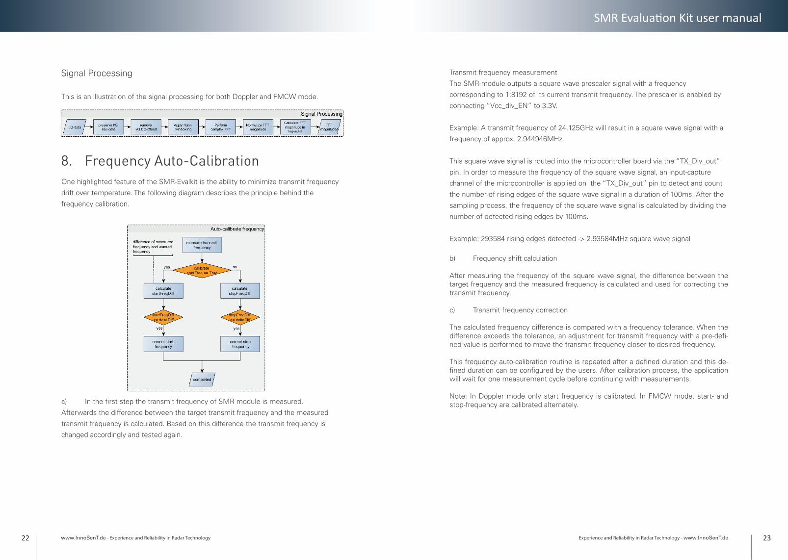
8. Frequency Auto-CalibrationOne highlighted feature of the SMR-Evalkit is the ability to minimize transmit frequency
drift over temperature. The following diagram describes the principle behind the
frequency calibration.
a) In the first step the transmit frequency of SMR module is measured.
Afterwards the difference between the target transmit frequency and the measured
transmit frequency is calculated. Based on this difference the transmit frequency is
changed accordingly and tested again.
Transmit frequency measurement
The SMR-module outputs a square wave prescaler signal with a frequency
corresponding to 1:8192 of its current transmit frequency. The prescaler is enabled by
connecting “Vcc_div_EN” to 3.3V.
Example: A transmit frequency of 24.125GHz will result in a square wave signal with a
frequency of approx. 2.944946MHz.
This square wave signal is routed into the microcontroller board via the “TX_Div_out”
pin. In order to measure the frequency of the square wave signal, an input-capture
channel of the microcontroller is applied on the “TX_Div_out” pin to detect and count
the number of rising edges of the square wave signal in a duration of 100ms. After the
sampling process, the frequency of the square wave signal is calculated by dividing the
number of detected rising edges by 100ms.
Example: 293584 rising edges detected -> 2.93584MHz square wave signal
b) Frequency shift calculation
After measuring the frequency of the square wave signal, the difference between the target frequency and the measured frequency is calculated and used for correcting the transmit frequency.
c) Transmit frequency correction
The calculated frequency difference is compared with a frequency tolerance. When the difference exceeds the tolerance, an adjustment for transmit frequency with a pre-defi-ned value is performed to move the transmit frequency closer to desired frequency.
This frequency auto-calibration routine is repeated after a defined duration and this de-fined duration can be configured by the users. After calibration process, the application will wait for one measurement cycle before continuing with measurements.
Note: In Doppler mode only start frequency is calibrated. In FMCW mode, start- and stop-frequency are calibrated alternately.

Experience and Reliability in Radar Technology - www.InnoSenT.dewww.InnoSenT.de - Experience and Reliability in Radar Technology
SMR Evaluati on Kit user manual
24 25
9. Complete Application Diagram 10. Hardware
Schematic circuit
11
22
33
44
55
66
77
88
DD
CC
BB
AA
11
Tite
lD
atum
Seite
von
Nam
e
gepr
üft
erst
ellt
20.0
3.20
17Ev
al-S
MR_
1.Pr
jPcb
Zirk
Dok
umen
tEv
al-S
MR_
1.Sc
hDoc
Cann
ot o
pen
file
C:\U
sers
\Pub
lic\D
ocum
ents
\Alti
um\A
D\
Tem
plat
es\L
ogo
Inno
SenT
cm
yk.p
ng
V-
4V+
8
IT33
10A
DA
4841
-2Y
RMZ
IC4A
-2
+3
Out
1
IT33
10A
DA
4841
-2Y
RMZ
IC4B -
6
+5
Out
7
IT33
10A
DA
4841
-2Y
RMZ
IC4C
V-
4V+
8
IT33
10A
DA
4841
-2Y
RMZ
IC5A
-6
+5
Out
7
IT33
10A
DA
4841
-2Y
RMZ
IC5C
n.b.
0402
C23
AT0
077
100n
C10
AT0
077
100n
C11
AT0
077
100n
C12
AT0
078
10µ
C13
AT0
083
1µC28
IT05
6110
k
R2IT05
6110
k
R1
AT0
094
100R
R31
Gnd
6
Vcc
Div
1
I3
Vcc
7
Div
Out
2V
tune
9
Q4
Vcc
Ptat
8
TXO
n5
Gnd
10
IT40
27SM
R-33
4
IC3
IT05
641kR2
6
-2
+3
Out
1
IT33
10A
DA
4841
-2Y
RMZ
IC5B
n.b.
0603
C29
Vmid1
Vmid2
AT0
083
1µC36
AT0
094
100R
R36
n.b.
0603
C37
Vmid1
Vmid2
GN
DG
ND
GN
DG
ND
GN
DG
ND
GN
D
Vm
id1
AT0
077
100n
C14
AT0
078
10µ
C15
IT05
6110
k
R4IT05
6110
k
R3
GN
DG
ND
GN
D
Vm
id2
GN
DG
ND
GN
DG
ND
Ref
6
Vre
g1
Byp
3
En7
Out
2
Ref_
Sens
5G
ND
4
In8
IT36
29A
DM
7154
ACP
Z-3.
3-R7
IC1
GN
D
AT0
077
100n
C8A
T007
810
µ
C7A
T007
510
0p
C9
GN
DG
ND
GN
D
AT0
078
10µ
C6
GN
D
AT0
083
1µC5G
ND
AT0
083
1µC4G
ND
GN
D
AT0
077
100n
C2
GN
DG
ND
AT0
075
100p
C3
Sign
al_Q
Sign
al_I
GN
D
GN
D
GN
D
Enab
le_V
CC
TX_O
NGN
D
AT0
078
10µ
C1
GN
D
IT00
730RR8
1 2
IT40
00LE
D g
rün
D2
IT07
3039
0R
R14
GN
D
+5V
CN
6
CN
5
CN
9
CN
8A
T007
710
0n
C19
GN
D
AT0
117
4k7
R25
3
1
2
AT0
046
FDV
304P
T3IT
0561
10k
R17
AT0
117
4k7
R18
IT07
3039
0R
R24
GN
D3
1
2IT03
43BC
W60
C
T5
AT0
117
4k7
R23
IT05
6110
k
R22
3
1
2
AT0
046
FDV
304P
T1IT
0561
10k
R12
AT0
117
4k7
R13
AT0
077
100n
C20
GN
D
IT07
3039
0R
R19
GN
D
+3V3
+3V3
VDD1
VREF2
VFB3
VOUT4 SYNC 5
SCLK 6
DIN 7
GND 8
AT0
171
AD
5662
WA
RMZ
IC2
IT00
730RR6
GN
D
AT0
026
100R
R9A
T002
610
0R
R10
AT0
026
100R
R11
AT0
026
100R
R5 AT0
083
1µC18
AT0
077
100n
C17
AT0
078
10µ
C16 G
ND
SPI_
CLK
SPI_
MO
SI
SPI_
CS
VCC_DIV
VCC_SMR
AT0
077
100n
C21
AT0
026
100RR7
GN
D
GN
D
GN
D
VCC
_SM
RVCC
_DIV
n.b.
0402
C26
n.b.
0402
C31
n.b.
0402
C34
1 2
IT40
00LE
D g
rün
D3
1 2
IT40
00LE
D g
rün
D4
12
IT40
00LE
D g
rün
D1
3
1
2
IT03
43BC
W60
C
T2 AT0
117
4k7
R16
IT05
6110
k
R15
GN
D
3
1
2
IT03
43BC
W60
C
T4
IT05
6110
k
R20
AT0
117
4k7
R21G
ND
TP4
V-tu
ne
TP2
Q-S
igna
l
TP1
Div
-out
TP3
I-Si
gnal
Vol
tage
-reg
ulat
ion
Sign
al-a
mpi
fier
DA
C (V
-Tun
e)
IT01
6410
0k
R39
2 31 4 5 6 7 8IT
4397
Stift
leis
te
X1
2 31 4 5 6 7 8IT
4397
Stift
leis
te
X2 2 31 4 5 6 7 8
IT43
97St
iftle
iste
X3
IT00
730RR4
0
23 1456
IT44
05St
iftle
iste
X4
AT0
078
10µ
C22
AT0
078
10µ
C30
IT11
961k
2
R27
IT11
961k
2
R32
IT11
961k
2
R29
IT11
961k
2
R34
IT05
6315
k
R28
IT05
6315
k
R33
IT12
013k
3
R30
IT12
013k
3
R35
IT26
895n
6
C24
IT26
895n
6
C32
AT0
078
10µ
C25
AT0
078
10µ
C33
IT27
7927
n
C27
IT27
7927
n
C35

Experience and Reliability in Radar Technology - www.InnoSenT.dewww.InnoSenT.de - Experience and Reliability in Radar Technology
SMR Evaluati on Kit user manual
26 27
Layout
TOP BOTTOM

www.InnoSenT.de - Experience and Reliability in Radar Technology28
11. References
SMR Technical characteristics
See Data Sheet SMR-334
STM32F401RE Nucleo reference manual:
http://www.st.com/content/ccc/resource/technical/document/reference_manual/5d/b1/
ef/b2/a1/66/40/80/DM00096844.pdf/files/DM00096844.pdf/jcr:content/translations/
en.DM00096844.pdf
STM32F401xE datasheet: http://www.st.com/content/ccc/resource/technical/document/
datasheet/30/91/86/2d/db/94/4a/d6/DM00102166.pdf/files/DM00102166.pdf/jcr:content/
translations/en.DM00102166.pdf
STM32 Nucleo-64 board user manual:
http://www.st.com/content/ccc/resource/technical/document/user_manual/98/2e/
fa/4b/e0/82/43/b7/DM00105823.pdf/files/DM00105823.pdf/jcr:content/translations/
en.DM00105823.pdf
Tel.: +49-9528-9518-0
Fax.: +49-9528-9518-99
E-mail: [email protected]
www.innosent.de
InnoSenT GmbH
Am Roedertor 30
97499 Donnersdorf
Germany
12. HistoryDocument revision
Date Change log Author
1 01.03.2017 first release BL
1.1 20.03.2017 Added description “Transmission State” SG
1.2 26.07.2017 Release CD
1.3 22.05.2018 Corrected USART2_TX/RX pins BL


![vÀ u v Àoµ }v^µ uu Ç~/ - aer.gov.au - Replace HV.../vÀ u v Àoµ }v^µ uu Ç~/ ^ W }i ] o W W }i E u W Replace HV potheads W }i / W 00674 dZ W Underground System W ylKW yW CAPEX](https://static.fdocuments.in/doc/165x107/5aa6fcea7f8b9ac5648b8252/v-u-v-o-v-uu-aergovau-replace-hvv-u-v-o-v-uu-w-i-o-w-w.jpg)


![vZ}]vvK] Z] Pµ ^ ]o vv u v }( µ ]}vv ^l]oo tZ}o ^ Z}}o Àoµ ...](https://static.fdocuments.in/doc/165x107/62131df4efac490c703f6124/vzvvk-z-p-o-vv-u-v-vv-loo-tzo-zo-o.jpg)


