
SMP Tiltrotator User Manual - En · SMP Tiltrotator User Manual Swingotilt ST6, ST10, ST12, ST15,...
38
SMP Tiltrotator User Manual Swingotilt ST6, ST10, ST12, ST15, ST22, ST28 ENGLISH
Transcript of SMP Tiltrotator User Manual - En · SMP Tiltrotator User Manual Swingotilt ST6, ST10, ST12, ST15,...

SMP Tiltrotator User Manual
SwingotiltST6, ST10, ST12, ST15, ST22, ST28
ENGLISH
Congratulations on your SMP purchase!Carefully study this user manual before using the product.The manual explains the safety aspects for using this product and how to get the most out if it to maximize the products life cycle.Take care of your SMP product and it will take care of you!
Welcome to SMP Parts AB.Do not hesitate to contact us for further information. www.smpparts.com
33
Contents
IntroductionAbout This Manual 4
General 4
Declaration of Conformity 6
Identification Plate 6
SafetySafety and Warnings 7
Technical SpecificationsTechnical Data 9
Control systemControl System 10
InstallationInstallation 11
Functions 12
Installation of the Electrical and Hydraulic System 13
Pre Delivery Inspection 20
OperationFunctions 22
Troubleshooting 23
Service and maintenanceService and Maintenance 24
Lubrication Chart 25
Spare partsST 6 26
ST 10 28
ST 12 30
ST 15 32
ST 22 34
ST 28 36
4
About This ManualThis user manual is intended to be used together with the SMP Tiltrotator during installation, operation and regular maintenance.
This manual is a guide of how to use and maintain the tiltrotator in a correct way.SMP reserves the right to change the contents of this manual at any time and without prior notice. This user manual can be ordered at SMP Parts.
The operator of the equipment must carefully study and make sure to fully understand this manual and its contents before using the equipment. The safety information given in this manual is only relevant to the SMP Tiltrotator independent of the carrier machine and tools.
This user manual is an original instruction according to the machinery directive: 2006/42/EG.
GeneralThe SMP Tiltrotator is installed into the excavator digger arm to enable tilting and rotation of a bucket or tool. The tools attached to the tiltrotator should be tools that are intended for use during work with an excavator.
The tiltrotator is not designed for and should not be used during a task that requires high torque, such as ploughing for cables or with a ripper.
To minimize the risk of personal injuries and damage to equipment and before using the equipment, make sure to read, understand and pay attention to all warnings given in signs and instructions on the equipment and in the instruction manuals.
Always make sure that there are no unauthorized persons located within the designated working area of the excavator.
Before using the equipment, make sure that the tiltrotator and equipment is completely fastened, both to the excavator and the tiltrotator quick coupler.
INTRODUCTION
5
A
B
D
CE
F
G
H
I
INTRODUCTION
Pos Description
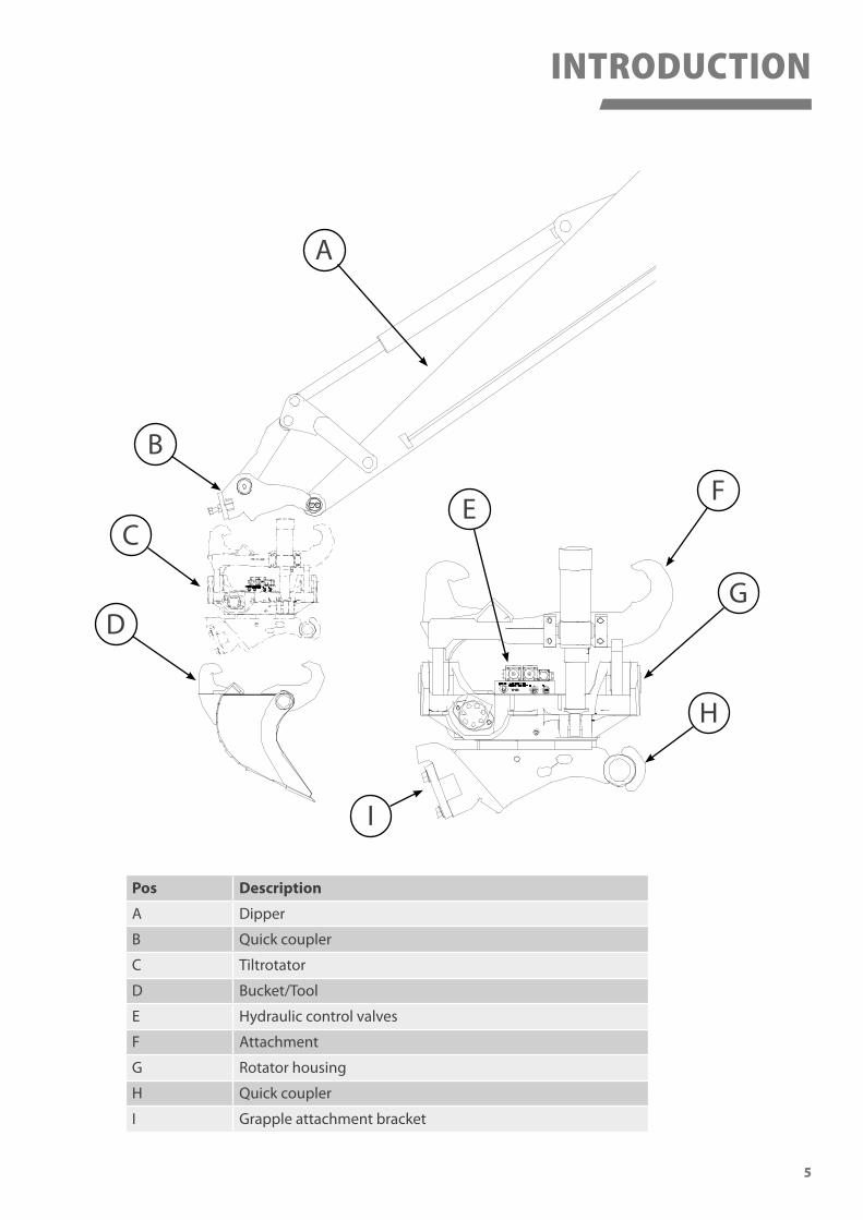
A Dipper
B Quick coupler
C Tiltrotator
D Bucket/Tool
E Hydraulic control valves
F Attachment
G Rotator housing
H Quick coupler
I Grapple attachment bracket

6
EG-Försäkran om överensstämmelse
Beskrivning av produkten:
Ansvarig för den tekniska dokumentationen:
Börje Blank, Bergsjövägen 3, 820 71 ILSBO. Ilsbo
Artikelnummer: Infästning: Kundordernummer: Tillverkningsnummer: Typ:
Den överstämmer också med följande, för produkten, förenliga föreskrifter.
Arbetsmiljöverkets föreskrift: AFS2008:3
konstruktion och i den version som marknadsföres av oss överensstämmer med
maskindirektivet 2006/42/EC. Vi vill påminna att ändringar på produkten utan vår
kännedom ogiltigförklarar denna försäkran.
Härmed förklarar vi att den produkt som beskrivs nedan i dess utformning och
Enligt maskindirektivet 2006/42/EC från 17 maj 2006, Bilaga II A
2014-12-08
Art.nr.
Type
Mfg.nr.
Weight
Mfg. Year
Coupler
Volume.
Tooth
Bergsjövägen 3SE-820 71 Ilsbo
Patented
I-SAE
kg
Art.
nr 6
0944
INTRODUCTION
Declaration of ConformitySMP Parts develop and manfacture all products in accordance with european legislation and the machinery directive 2006/42/EG. Together with the delivered products there is also a CE certificate that guarantees that the equipment is manufactured according to legislation.
Identification PlateThe identification plate gives information about the model designation, serial number and manufacturing year. There is also a CE-logotype on the plate indicating that the product fulfills the machinery directive.
Fill the fields with the information copied from the manufacturing plate on the tiltrotator.

7
SAFETY
General Warning Signs on Machinery Equipment
WARNING
READ THE USER MANUAL
NEVER STAND UNDER A LOAD
RISK OF CRUSHING BY MOVING PARTS
Safety and WarningsThis chapter describes safety related information that needs to be taken into consideration before, during and after using the equipment.
DANGER, WARNING, CAUTION and Note statements are used throughout this manual to emphasize important and critical information. You must read these statements to help ensure safety and to prevent damage to the product. The statements are defined below.
DANGER indicates an imminently hazardous situation which, if not avoided, will result in death or serious injury. This signal word is to be limited to the most extreme situations.
WARNING indicates a potentially hazardous situation which, if not avoided, could result in death or serious injury.
CAUTION indicates a potentially hazardous situation which, if not avoided, could result in minor or moderate injury. It may also be used to alert against unsafe practices.
Note: A note statement is used to notify people of installation, operation or maintenance information that is important, but not hazard-related.
8
SAFETY
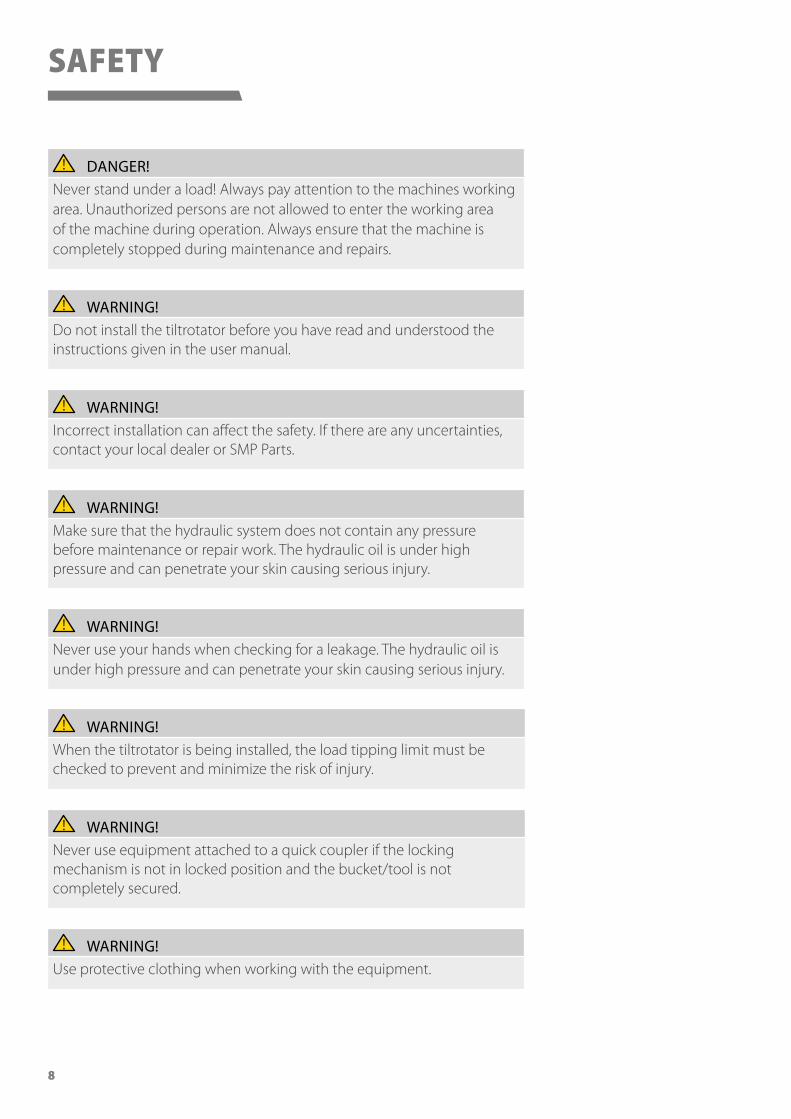
DANGER!Never stand under a load! Always pay attention to the machines working area. Unauthorized persons are not allowed to enter the working area of the machine during operation. Always ensure that the machine is completely stopped during maintenance and repairs.
WARNING!Do not install the tiltrotator before you have read and understood the instructions given in the user manual.
WARNING!Incorrect installation can affect the safety. If there are any uncertainties, contact your local dealer or SMP Parts.
WARNING!Make sure that the hydraulic system does not contain any pressure before maintenance or repair work. The hydraulic oil is under high pressure and can penetrate your skin causing serious injury.
WARNING!Never use your hands when checking for a leakage. The hydraulic oil is under high pressure and can penetrate your skin causing serious injury.
WARNING!When the tiltrotator is being installed, the load tipping limit must be checked to prevent and minimize the risk of injury.
WARNING!Never use equipment attached to a quick coupler if the locking mechanism is not in locked position and the bucket/tool is not completely secured.
WARNING!Use protective clothing when working with the equipment.
9
A
B D
C
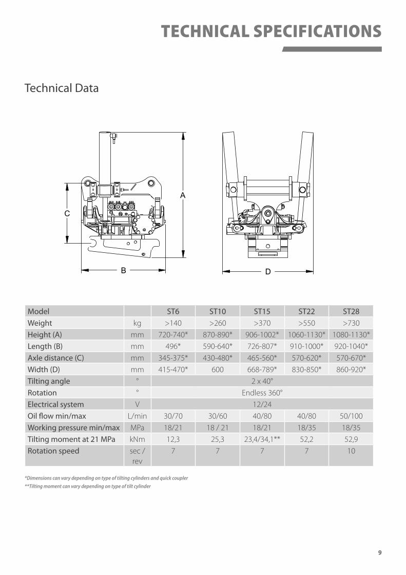
Model ST6 ST10 ST15 ST22 ST28Weight kg >140 >260 >370 >550 >730
Height (A) mm 720-740* 870-890* 906-1002* 1060-1130* 1080-1130*
Length (B) mm 496* 590-640* 726-807* 910-1000* 920-1040*
Axle distance (C) mm 345-375* 430-480* 465-560* 570-620* 570-670*
Width (D) mm 415-470* 600 668-789* 830-850* 860-920*
Tilting angle ° 2 x 40°
Rotation ° Endless 360°
Electrical system V 12/24
Oil flow min/max L/min 30/70 30/60 40/80 40/80 50/100
Working pressure min/max MPa 18/21 18 / 21 18/21 18/35 18/35
Tilting moment at 21 MPa kNm 12,3 25,3 23,4/34,1** 52,2 52,9
Rotation speed sec / rev
7 7 7 7 10
TECHNICAL SPECIFICATIONS
Technical Data
*Dimensions can vary depending on type of tilting cylinders and quick coupler
**Tilting moment can vary depending on type of tilt cylinder

10
Control System
The tiltrotator is equipped with different types of control systems and valves based on customer needs and the model of the tiltrotator.
Control Systems TS-TSXCThe tiltrotator is connected to the excavators double acting auxiliary hydraulics. The manoeuvring is performed via the excavators control system with joystick handle thumb rollers or rocker switch.
Control System TXXSC - TXXC - Tiltrotator with Grip ModuleThe tiltrotator is connected to the excavators double acting auxiliary hydraulics. The manoeuvring is performed via the excavators control system with joystick handle thumb rollers or rocker switch.
Control System P and PRO macs RTThe tiltrotator is connected to the excavators single acting auxiliary hydraulics and is operated with the control system provided by SMP. The tilt and rotor functions of the PRO system have proportionally controlled valves to enable exact precision during operation.
NOTE!The quick coupler locking mechanism will only function properly with quick couplers provided by SMP. If any other type of quick coupler is to be installaed, contact SMP for information regarding functionality and how to install.
CONTROL SYSTEM
11
INSTALLATION
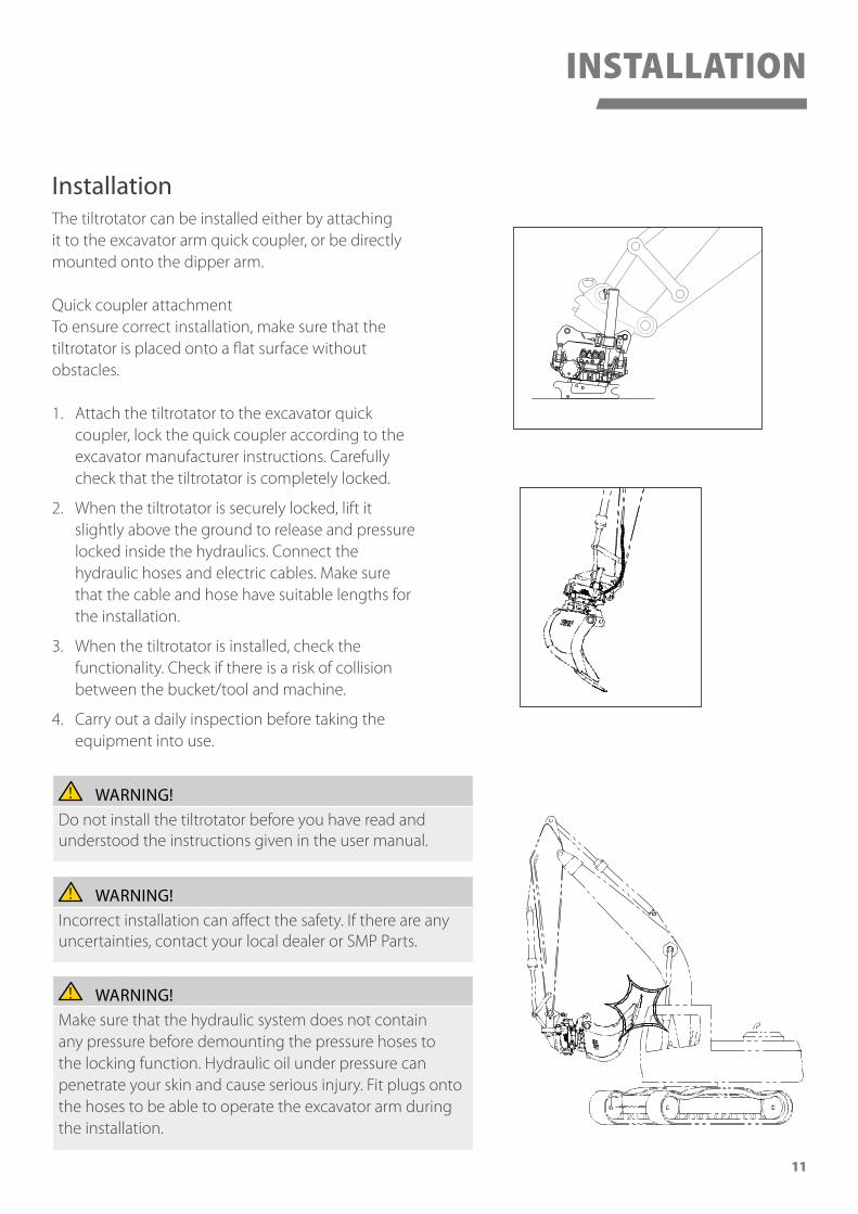
WARNING!Make sure that the hydraulic system does not contain any pressure before demounting the pressure hoses to the locking function. Hydraulic oil under pressure can penetrate your skin and cause serious injury. Fit plugs onto the hoses to be able to operate the excavator arm during the installation.
WARNING!Do not install the tiltrotator before you have read and understood the instructions given in the user manual.
WARNING!Incorrect installation can affect the safety. If there are any uncertainties, contact your local dealer or SMP Parts.
InstallationThe tiltrotator can be installed either by attaching it to the excavator arm quick coupler, or be directly mounted onto the dipper arm.
Quick coupler attachmentTo ensure correct installation, make sure that the tiltrotator is placed onto a flat surface without obstacles.
1. Attach the tiltrotator to the excavator quick coupler, lock the quick coupler according to the excavator manufacturer instructions. Carefully check that the tiltrotator is completely locked.
2. When the tiltrotator is securely locked, lift it slightly above the ground to release and pressure locked inside the hydraulics. Connect the hydraulic hoses and electric cables. Make sure that the cable and hose have suitable lengths for the installation.
3. When the tiltrotator is installed, check the functionality. Check if there is a risk of collision between the bucket/tool and machine.
4. Carry out a daily inspection before taking the equipment into use.
12
INSTALLATION
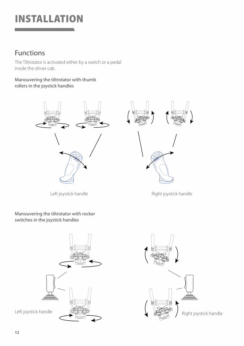
FunctionsThe Tiltrotator is activated either by a switch or a pedal inside the driver cab.
Manouvering the tiltrotator with thumb rollers in the joystick handles
Left joystick handle
Left joystick handle
Right joystick handle
Right joystick handle
Manouvering the tiltrotator with rocker switches in the joystick handles

13
INSTALLATION
Installation of the Electrical and Hydraulic SystemThe Tiltrotator electrics and hydraulics are installed depending on the type of machine, equipment and control system. Always follow the machine manufacturers instructions and guidelines of how to install auxiliary equipment in a safe and correct way.
Connecting the HydraulicsThe hydraulic system is designed to work with a hydraulic pressure of 21 Mpa and a flow of 60 l/min.The type, size and length of hydraulic hoses and couplings can differ depending on type of machine. Therefore it is sometimes neccesary to make new hoses locally. Ensure that the hydraulic hoses are the correct length to prevent damage which can be caused by stretching or crushing.
Make sure that the hydraulic hoses and nipples are fitted and tightened according to the supplier recommendations.
Connecting the ElectricsThe electrical components are designed to function both with 12V or 24V. Ensure that the cabling is the correct length to prevent damage which can be caused by stretching or crushing.
WARNING!Always make sure to fuse up the power lead wire in case of a short circuit in the electrical system. An electrical short circuit can cause damage to the excavator electrical system, or in worst case cause a fire that could lead to serious injury or death.
14
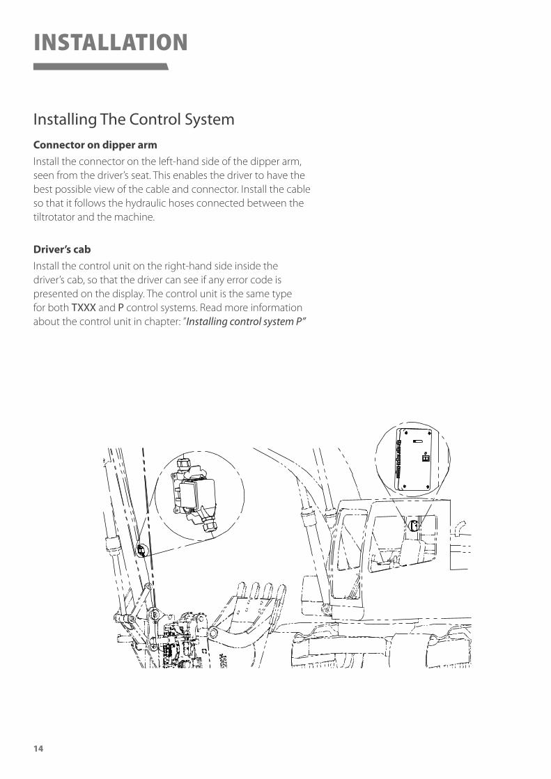
Installing The Control SystemConnector on dipper armInstall the connector on the left-hand side of the dipper arm, seen from the driver’s seat. This enables the driver to have the best possible view of the cable and connector. Install the cable so that it follows the hydraulic hoses connected between the tiltrotator and the machine.
Driver’s cabInstall the control unit on the right-hand side inside the driver’s cab, so that the driver can see if any error code is presented on the display. The control unit is the same type for both TXXX and P control systems. Read more information about the control unit in chapter: ”Installing control system P”
INSTALLATION
15
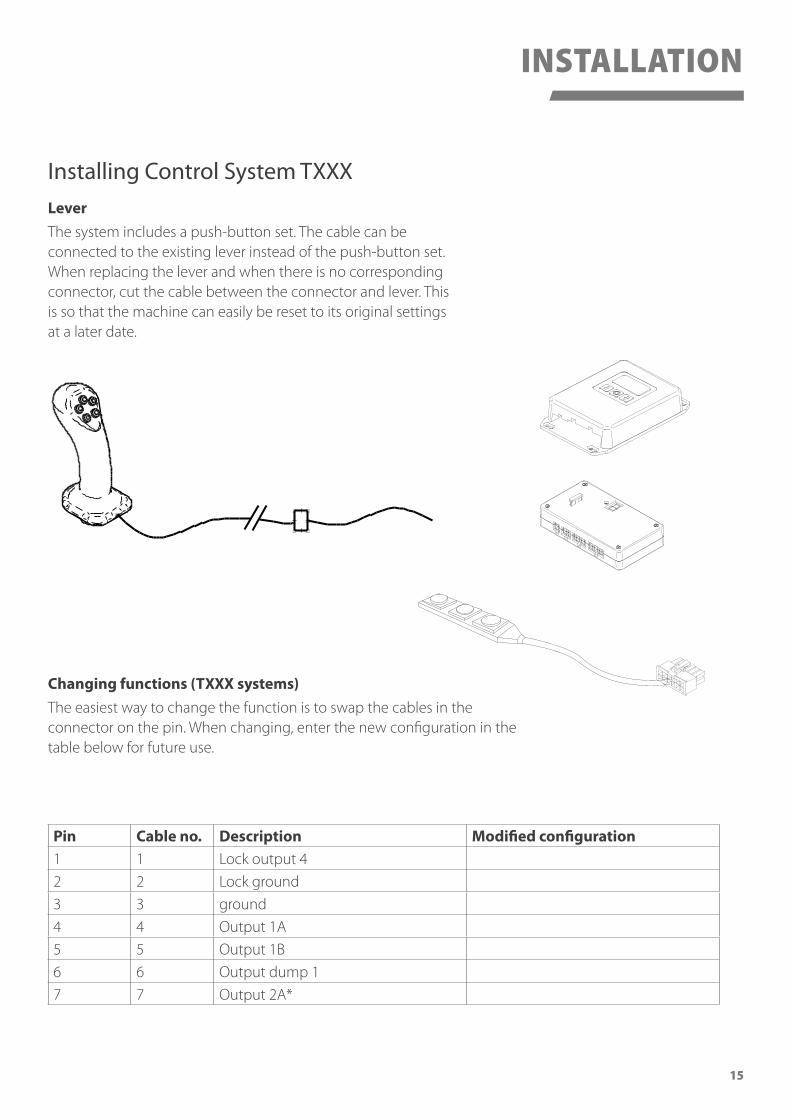
Changing functions (TXXX systems)The easiest way to change the function is to swap the cables in the connector on the pin. When changing, enter the new configuration in the table below for future use.
Pin Cable no. Description Modified configuration1 1 Lock output 4
2 2 Lock ground
3 3 ground
4 4 Output 1A
5 5 Output 1B
6 6 Output dump 1
7 7 Output 2A*
Installing Control System TXXXLeverThe system includes a push-button set. The cable can be connected to the existing lever instead of the push-button set. When replacing the lever and when there is no corresponding connector, cut the cable between the connector and lever. This is so that the machine can easily be reset to its original settings at a later date.
INSTALLATION

16
Installing Control System PFunction descriptionThe control unit can drive 6+1 valves as well as 1 x DUMP. The DUMP signal is active when oneof the other functions is activated. The DUMP function activates the auxiliary hydraulics on the excavator to distribute oil flow to the tiltrotator. The control unit is short-circuit protected and automatically reduces the current in the event of overload.
+12/24VPower input from the excavator battery och ignition switch.
SwitchThe switch connects inputs for quick coupling buttons and output signals for dump.The dump signal is received as both supply voltage and ground.
OutputOutput signals to valves on the tiltrotator.
InputInput signals from function switches.
Jumper settingsJumper INPUT is to select positive or negative control on the INPUT connector.Jumper INP CHK is to activate fault control on in signals.Activated error control disconnects all functions, if a function is activated with current on.To resume, cancel and reset the current to the control unit.
Error messages/ fault-tracingShort flash:The error lamp flashes when a function is activated. This is completely normal.
Continuous light:If the error lamp lights continuously when a function is activated, this output has a shortcircuit.
Continuous light when the quick coupling function is activated (Control system P only):The error lamp lights continuously if one of the outputs is interrupted, i.e. there is no contact withthe magnet coil on the valve.The error lamp goes out when the interrupted output is activated. NOTE. If several outputs areinterrupted, all outputs must be activated to extinguish the error lamp.
NOTE!Starting the excavator with battery booster:Always disconnect the control unit to protect it from over-voltage!
INSTALLATION
17
7.5
Art
nr: 6
3598
Inpu
t jum
per
Error
+12/24V Output
Switch Input
Fuse 7.5 AmpQuickcoupler
Dump
Bucket
1A3B
1B
2A3A
2B
Gnd
(Gnd) +out
+in
Gnd
Gnd
1A 1B 2A 1B 3A
3BGnd GndGnd
+
(+) +
+
1A 1B 2A 1B 3A 3B
+/- +/- +/- +/- +/- +/-
+
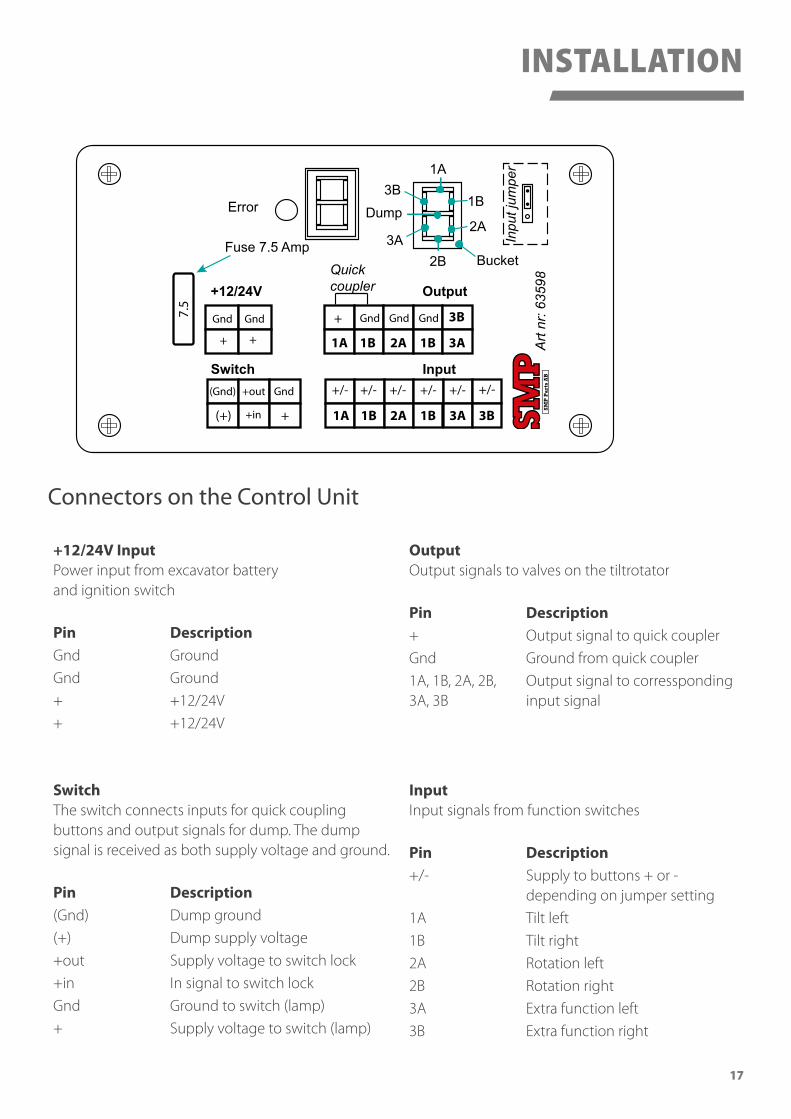
+12/24V InputPower input from excavator battery and ignition switch
Pin DescriptionGnd Ground
Gnd Ground
+ +12/24V
+ +12/24V
SwitchThe switch connects inputs for quick coupling buttons and output signals for dump. The dump signal is received as both supply voltage and ground.
Pin Description(Gnd) Dump ground
(+) Dump supply voltage
+out Supply voltage to switch lock
+in In signal to switch lock
Gnd Ground to switch (lamp)
+ Supply voltage to switch (lamp)
OutputOutput signals to valves on the tiltrotator
Pin Description+ Output signal to quick coupler
Gnd Ground from quick coupler
1A, 1B, 2A, 2B, 3A, 3B
Output signal to corressponding input signal
InputInput signals from function switches
Pin Description+/- Supply to buttons + or -
depending on jumper setting
1A Tilt left
1B Tilt right
2A Rotation left
2B Rotation right
3A Extra function left
3B Extra function right
Connectors on the Control Unit
INSTALLATION
18
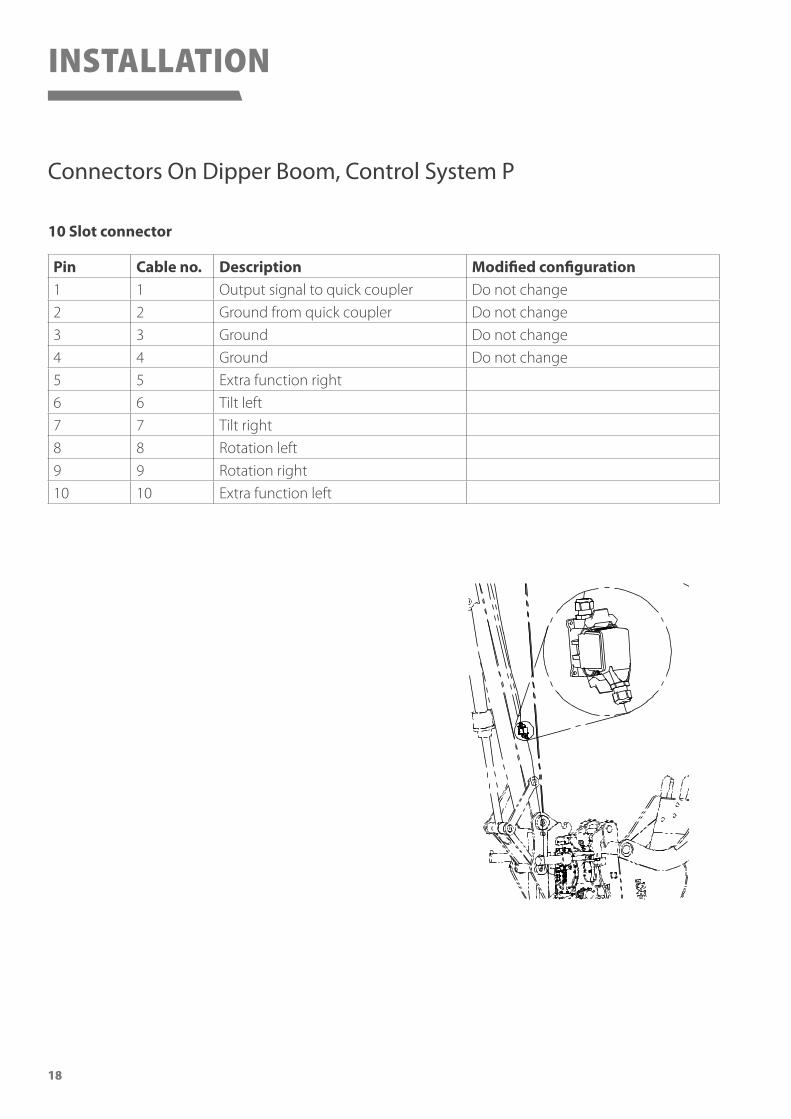
Pin Cable no. Description Modified configuration1 1 Output signal to quick coupler Do not change
2 2 Ground from quick coupler Do not change
3 3 Ground Do not change
4 4 Ground Do not change
5 5 Extra function right
6 6 Tilt left
7 7 Tilt right
8 8 Rotation left
9 9 Rotation right
10 10 Extra function left
10 Slot connector
Connectors On Dipper Boom, Control System P
INSTALLATION

19
INSTALLATION
14 Slot connector
Pin Cable no. Description1 1, 12 Ground, solenoid 1A, 1B
2 2 Solenoid 1A tilt left
3 3 Solenoid 1B tilt right
4 4, 13 Ground, solenoid 2A, 2B
5 5 Solenoid 2A rotation right
6 6 Solenoid 2B rotation left
7 7, 14 Ground, solenoid 3A, 3B
8 8 Solenoid 3A extra 1
9 9 Solenoid 3B extra 1
10 10 Ground from quick coupler
11 11 Output signal to quick coupler
12 15, 17 Ground, solenoid 5A, 5B
13 16 Solenoid 5A, Extra 2
14 18 Solenoid 5B, Extra 2
Installing Control System PRO Macs STFor installation instructions of the control system PRO, read separate manual.
Connectors On Dipper Boom, Control System PRO Macs ST
20
Pre Delivery InspectionAfter the installation is completed:1. Check the functionality of the tiltrotator.
2. Check for leakages on the hydraulic system.
3. Attach a bucket or a tool and operate the tiltrotator to its end positions.
4. Check and make sure that the tiltrotator, bucket or tool is perfectly secured and that no hoses or cables are stretched or crushed.
5. Grease according to lubrication chart.
6. Clean the equipment before delivery to end customer.
7. Fill in local after sales contact information on the back cover of this manual.
8. Copy the information from the manufacturing plate and fill in the corresponding fields on the manufacturing plate, illustrated on page 6 of this manual.
9. Place this manual together with other documentation in the carrier machine.
INSTALLATION
21
OPERATION
WARNING!Before taking the Tiltrotaror into use, make sure that you have read and fully understood the instructions of how to use and operate the tiltrotator.
WARNING!This manual only covers parts related to the tiltrotator and is a complement to the carrier vehicle user manual. Make sure to read and fully understand the instructions given for how to operate the carrier vehicle before taking this Tiltrotator into use.
DANGER!Never stand under a load! Always pay attention to the machines working area. Unauthorized persons are not allowed to enter the working area of the machine during operation. Always ensure that the machine is completely stopped during maintenance and repairs.
WARNING!Do not install the tiltrotator before you have read and understood the instructions given in the user manual.
WARNING!Never use equipment attached to a quick coupler if the locking mechanism is not in locked position.
22
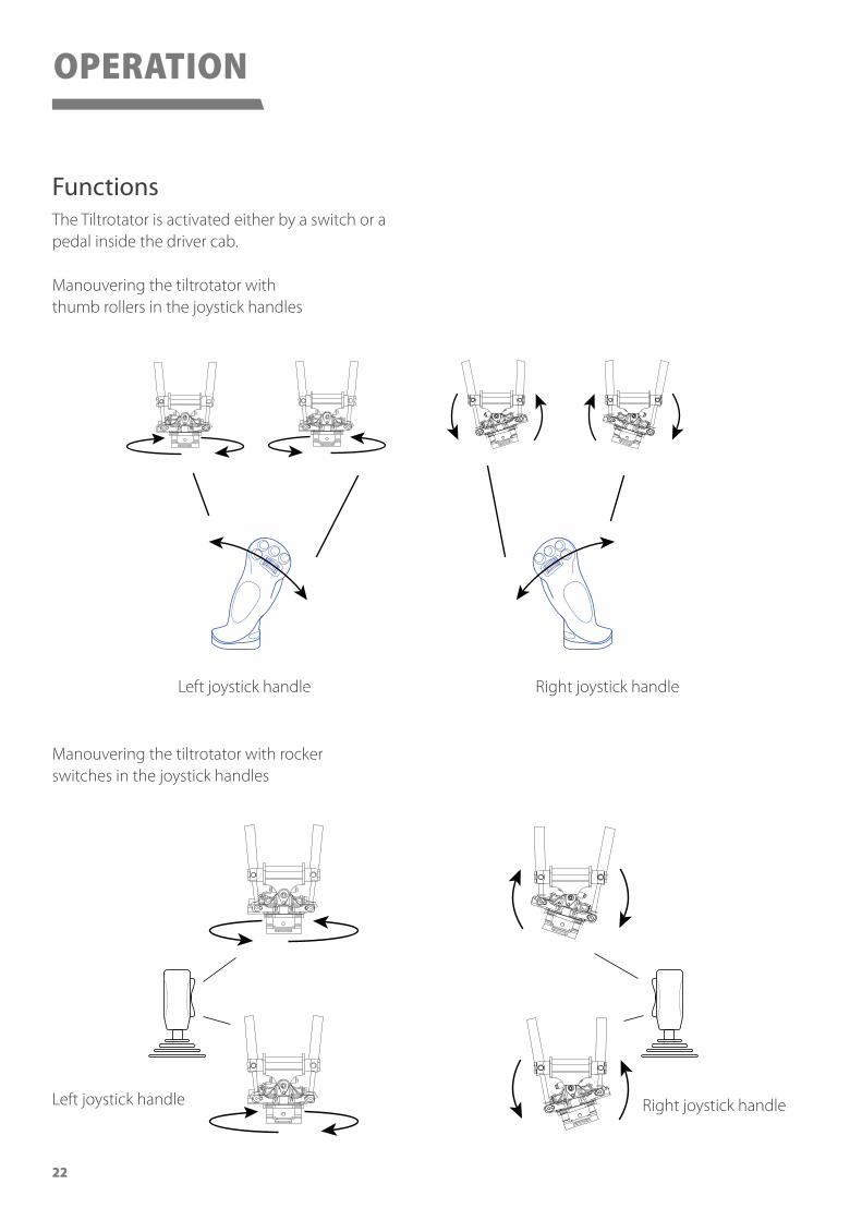
FunctionsThe Tiltrotator is activated either by a switch or a pedal inside the driver cab.
Manouvering the tiltrotator with thumb rollers in the joystick handles
Left joystick handle
Left joystick handle
Right joystick handle
Right joystick handle
Manouvering the tiltrotator with rocker switches in the joystick handles
OPERATION
23
Art.nr.
Type
Mfg.nr.
Weight
Mfg. Year
Coupler
Volume.
Tooth
Bergsjövägen 3SE-820 71 Ilsbo
Patented
I-SAE
kg
Art.
nr 6
0944
CAUTION!Always use protective clothing when working with the equipment.
WARNING!The machine must always be completely turned off during service and maintenance.
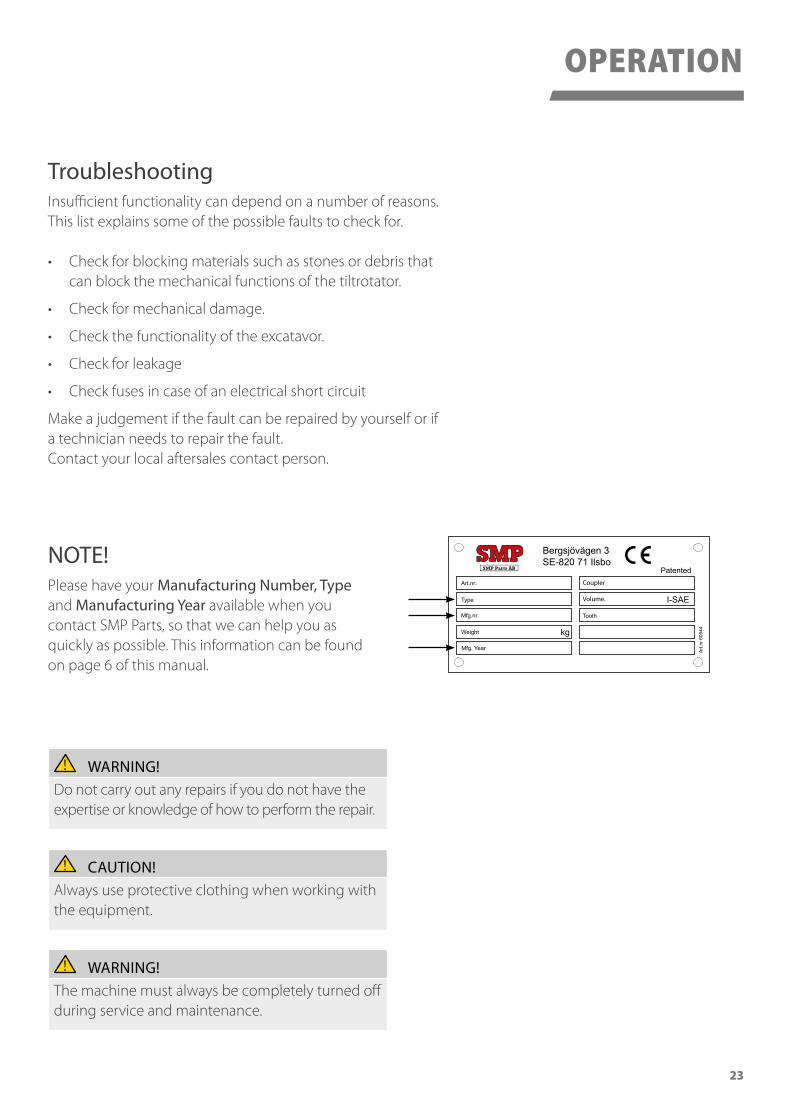
TroubleshootingInsufficient functionality can depend on a number of reasons. This list explains some of the possible faults to check for.
• Check for blocking materials such as stones or debris that can block the mechanical functions of the tiltrotator.
• Check for mechanical damage.
• Check the functionality of the excatavor.
• Check for leakage
• Check fuses in case of an electrical short circuit
Make a judgement if the fault can be repaired by yourself or if a technician needs to repair the fault. Contact your local aftersales contact person.
WARNING!Do not carry out any repairs if you do not have the expertise or knowledge of how to perform the repair.
OPERATION
NOTE!Please have your Manufacturing Number, Type and Manufacturing Year available when you contact SMP Parts, so that we can help you as quickly as possible. This information can be found on page 6 of this manual.
24
Daily Maintenance• Operate the tiltrotator to check its functionality.
• Visually check shaft locking pins and nuts.
• Check for leakages in the hydraulic system.
• Check for cracks and damage.
• Check that the quick coupler is correctly fastened to both the excavator and the bucket.
• Clean the tiltrotator from dirt.
• Lubricate according to lubrication chart.
• Check for axial play, contact your SMP after sales contact person if needed.
• Check fastenings on shafts, tighten locking screws and nuts if needed.
Maintenance every 6 months or 500 operating hours (whichever comes first)• Tightening of the tilt cylinder bracket clamp.
• Check and re-tighten screws on tilt cylinder shafts.
Annual Maintenance or 1000 operating hours (whichever comes first)• Check and re-tighten screws on the swivel joint bolting (to be carried out by a SMP
authorized workshop).
CAUTION!Always use protective clothing when working with the equipment.
WARNING!The machine must always be completely turned off during service and maintenance.
Service and MaintenanceTo ensure a long life cycle and to get the most out of the products, regular service and maintenance is of high importance.
SERVICE AND MAINTENANCE
25
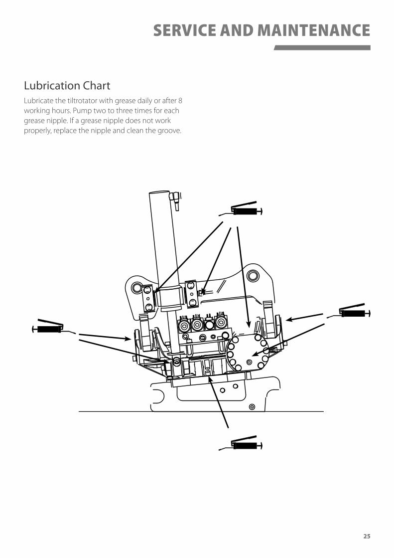
Lubrication ChartLubricate the tiltrotator with grease daily or after 8 working hours. Pump two to three times for each grease nipple. If a grease nipple does not work properly, replace the nipple and clean the groove.
SERVICE AND MAINTENANCE
26
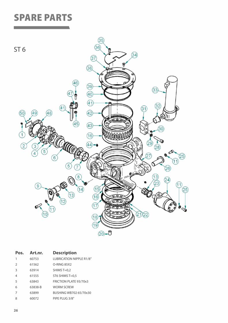
Pos. Art.nr. Description1 60753 LUBRICATION NIPPLE R1/8”
2 61562 O-RING 85X2
3 63914 SHIMS T=0,2
4 61555 ST6 SHIMS T=0,5
5 63843 FRICTION PLATE 93/70x3
6 63838-B WORM SCREW
7 63899 BUSHING WB702 65/70x30
8 60072 PIPE PLUG 3/8"
ST 6
SPARE PARTS
27
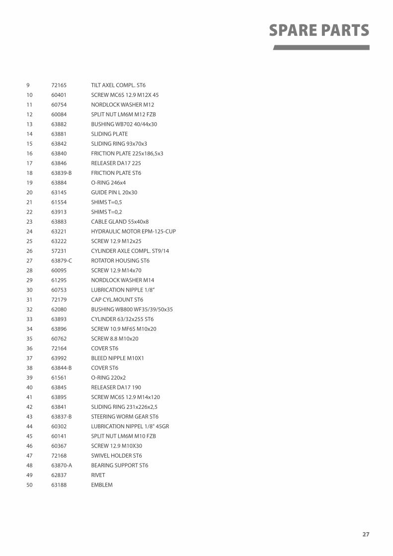
9 72165 TILT AXEL COMPL. ST6
10 60401 SCREW MC6S 12.9 M12X 45
11 60754 NORDLOCK WASHER M12
12 60084 SPLIT NUT LM6M M12 FZB
13 63882 BUSHING WB702 40/44x30
14 63881 SLIDING PLATE
15 63842 SLIDING RING 93x70x3
16 63840 FRICTION PLATE 225x186,5x3
17 63846 RELEASER DA17 225
18 63839-B FRICTION PLATE ST6
19 63884 O-RING 246x4
20 63145 GUIDE PIN L 20x30
21 61554 SHIMS T=0,5
22 63913 SHIMS T=0,2
23 63883 CABLE GLAND 55x40x8
24 63221 HYDRAULIC MOTOR EPM-125-CUP
25 63222 SCREW 12.9 M12x25
26 57231 CYLINDER AXLE COMPL. ST9/14
27 63879-C ROTATOR HOUSING ST6
28 60095 SCREW 12.9 M14x70
29 61295 NORDLOCK WASHER M14
30 60753 LUBRICATION NIPPLE 1/8”
31 72179 CAP CYL.MOUNT ST6
32 62080 BUSHING WB800 WF35/39/50x35
33 63893 CYLINDER 63/32x255 ST6
34 63896 SCREW 10.9 MF6S M10x20
35 60762 SCREW 8.8 M10x20
36 72164 COVER ST6
37 63992 BLEED NIPPLE M10X1
38 63844-B COVER ST6
39 61561 O-RING 220x2
40 63845 RELEASER DA17 190
41 63895 SCREW MC6S 12.9 M14x120
42 63841 SLIDING RING 231x226x2,5
43 63837-B STEERING WORM GEAR ST6
44 60302 LUBRICATION NIPPEL 1/8" 45GR
45 60141 SPLIT NUT LM6M M10 FZB
46 60367 SCREW 12.9 M10X30
47 72168 SWIVEL HOLDER ST6
48 63870-A BEARING SUPPORT ST6
49 62837 RIVET
50 63188 EMBLEM
SPARE PARTS
28
ST 10
19
3038
40
16
43
26
15
1
3
67
10
12
18
35
214
17
50
47
48
49
21
3746
34 32
44
23
3133
27
45
39
8
24
36
25
20
542
419
411
13
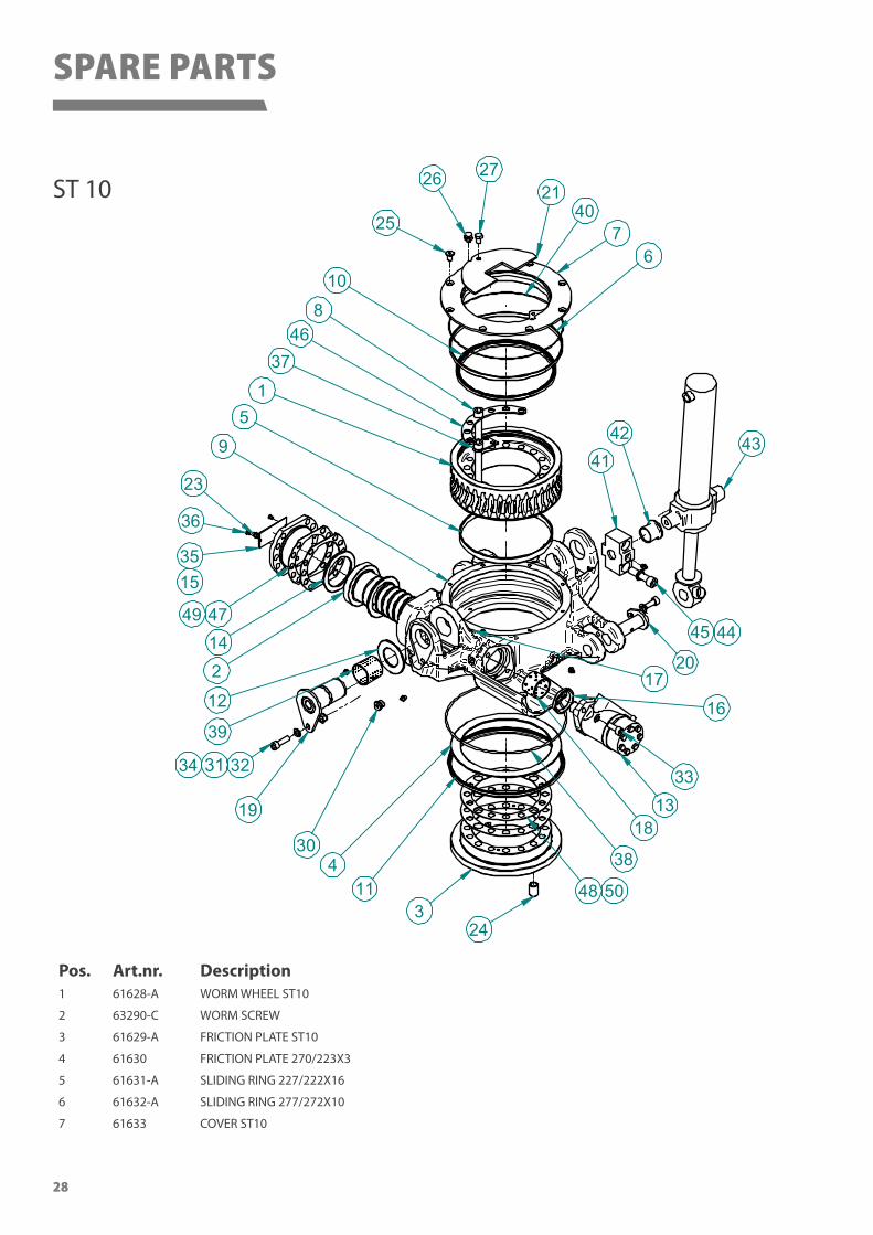
Pos. Art.nr. Description1 61628-A WORM WHEEL ST10
2 63290-C WORM SCREW
3 61629-A FRICTION PLATE ST10
4 61630 FRICTION PLATE 270/223X3
5 61631-A SLIDING RING 227/222X16
6 61632-A SLIDING RING 277/272X10
7 61633 COVER ST10
SPARE PARTS
29
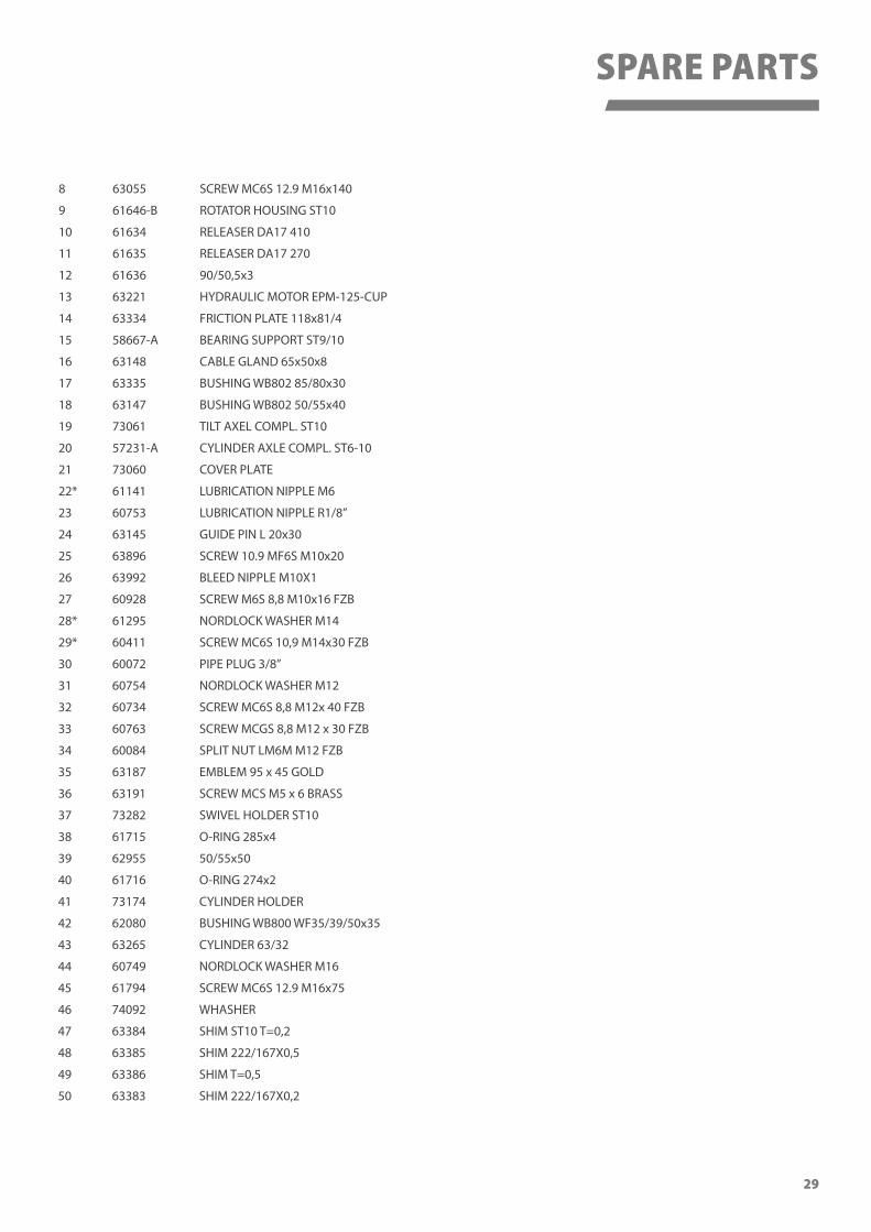
8 63055 SCREW MC6S 12.9 M16x140
9 61646-B ROTATOR HOUSING ST10
10 61634 RELEASER DA17 410
11 61635 RELEASER DA17 270
12 61636 90/50,5x3
13 63221 HYDRAULIC MOTOR EPM-125-CUP
14 63334 FRICTION PLATE 118x81/4
15 58667-A BEARING SUPPORT ST9/10
16 63148 CABLE GLAND 65x50x8
17 63335 BUSHING WB802 85/80x30
18 63147 BUSHING WB802 50/55x40
19 73061 TILT AXEL COMPL. ST10
20 57231-A CYLINDER AXLE COMPL. ST6-10
21 73060 COVER PLATE
22* 61141 LUBRICATION NIPPLE M6
23 60753 LUBRICATION NIPPLE R1/8”
24 63145 GUIDE PIN L 20x30
25 63896 SCREW 10.9 MF6S M10x20
26 63992 BLEED NIPPLE M10X1
27 60928 SCREW M6S 8,8 M10x16 FZB
28* 61295 NORDLOCK WASHER M14
29* 60411 SCREW MC6S 10,9 M14x30 FZB
30 60072 PIPE PLUG 3/8”
31 60754 NORDLOCK WASHER M12
32 60734 SCREW MC6S 8,8 M12x 40 FZB
33 60763 SCREW MCGS 8,8 M12 x 30 FZB
34 60084 SPLIT NUT LM6M M12 FZB
35 63187 EMBLEM 95 x 45 GOLD
36 63191 SCREW MCS M5 x 6 BRASS
37 73282 SWIVEL HOLDER ST10
38 61715 O-RING 285x4
39 62955 50/55x50
40 61716 O-RING 274x2
41 73174 CYLINDER HOLDER
42 62080 BUSHING WB800 WF35/39/50x35
43 63265 CYLINDER 63/32
44 60749 NORDLOCK WASHER M16
45 61794 SCREW MC6S 12.9 M16x75
46 74092 WHASHER
47 63384 SHIM ST10 T=0,2
48 63385 SHIM 222/167X0,5
49 63386 SHIM T=0,5
50 63383 SHIM 222/167X0,2
SPARE PARTS
30
SPARE PARTS
ST 12
11
22
12
10
46
5
8
1
15
2
9
3
7
13 16
1718
19
21
2324
1427
25
26
20
29
30
31
34
32
35
36
33
38
42
41
37
40
45
46
44
39
43
47
48
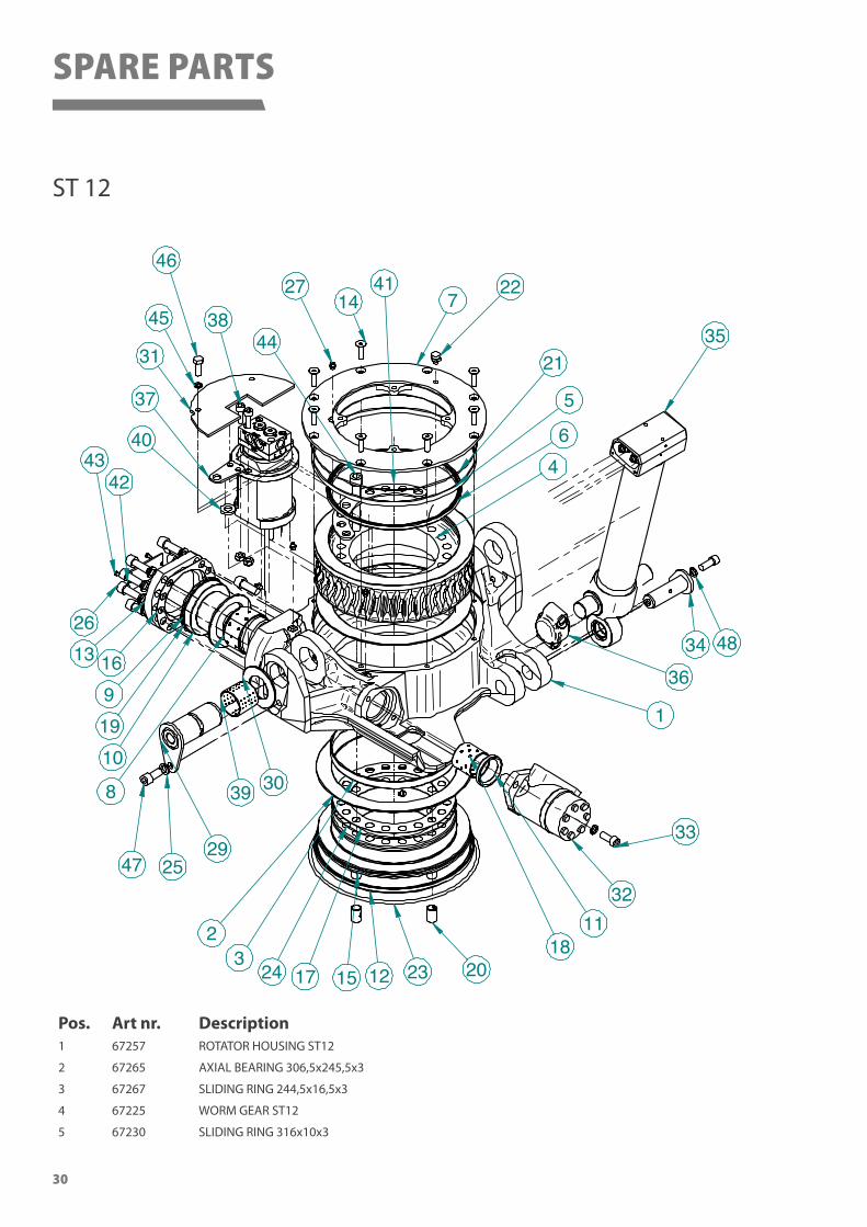
Pos. Art nr. Description1 67257 ROTATOR HOUSING ST12
2 67265 AXIAL BEARING 306,5x245,5x3
3 67267 SLIDING RING 244,5x16,5x3
4 67225 WORM GEAR ST12
5 67230 SLIDING RING 316x10x3
31
SPARE PARTS
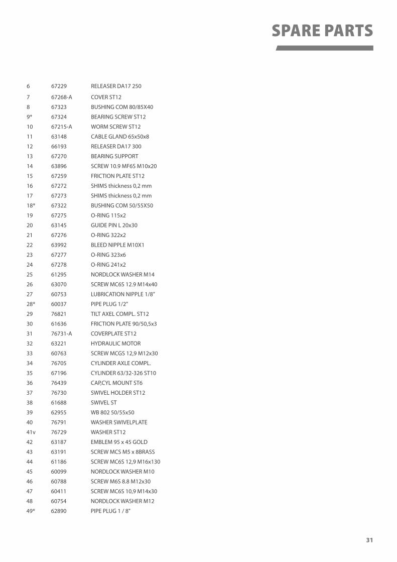
6 67229 RELEASER DA17 250
7 67268-A COVER ST12
8 67323 BUSHING COM 80/85X40
9* 67324 BEARING SCREW ST12
10 67215-A WORM SCREW ST12
11 63148 CABLE GLAND 65x50x8
12 66193 RELEASER DA17 300
13 67270 BEARING SUPPORT
14 63896 SCREW 10.9 MF6S M10x20
15 67259 FRICTION PLATE ST12
16 67272 SHIMS thickness 0,2 mm
17 67273 SHIMS thickness 0,2 mm
18* 67322 BUSHING COM 50/55X50
19 67275 O-RING 115x2
20 63145 GUIDE PIN L 20x30
21 67276 O-RING 322x2
22 63992 BLEED NIPPLE M10X1
23 67277 O-RING 323x6
24 67278 O-RING 241x2
25 61295 NORDLOCK WASHER M14
26 63070 SCREW MC6S 12.9 M14x40
27 60753 LUBRICATION NIPPLE 1/8”
28* 60037 PIPE PLUG 1/2"
29 76821 TILT AXEL COMPL. ST12
30 61636 FRICTION PLATE 90/50,5x3
31 76731-A COVERPLATE ST12
32 63221 HYDRAULIC MOTOR
33 60763 SCREW MCGS 12,9 M12x30
34 76705 CYLINDER AXLE COMPL.
35 67196 CYLINDER 63/32-326 ST10
36 76439 CAP,CYL MOUNT ST6
37 76730 SWIVEL HOLDER ST12
38 61688 SWIVEL ST
39 62955 WB 802 50/55x50
40 76791 WASHER SWIVELPLATE
41v 76729 WASHER ST12
42 63187 EMBLEM 95 x 45 GOLD
43 63191 SCREW MCS M5 x 8BRASS
44 61186 SCREW MC6S 12,9 M16x130
45 60099 NORDLOCK WASHER M10
46 60788 SCREW M6S 8.8 M12x30
47 60411 SCREW MC6S 10,9 M14x30
48 60754 NORDLOCK WASHER M12
49* 62890 PIPE PLUG 1 / 8"
32
12
3 4
5 4
6 7 8
1 213
12
11 10
27
14
24 2322
21
46 45
9
18
1920
25
4122
50
49
43
42
44
21
2240
353433
32
212229
26
3031
3736
39
28
4847
151617
14
38
51
52
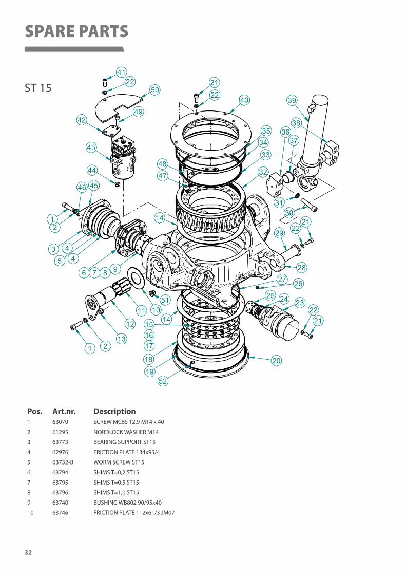
Pos. Art.nr. Description1 63070 SCREW MC6S 12.9 M14 x 40
2 61295 NORDLOCK WASHER M14
3 63773 BEARING SUPPORT ST15
4 62976 FRICTION PLATE 134x95/4
5 63732-B WORM SCREW ST15
6 63794 SHIMS T=0,2 ST15
7 63795 SHIMS T=0,5 ST15
8 63796 SHIMS T=1,0 ST15
9 63740 BUSHING WB802 90/95x40
10 63746 FRICTION PLATE 112x61/3 JM07
ST 15
SPARE PARTS
33
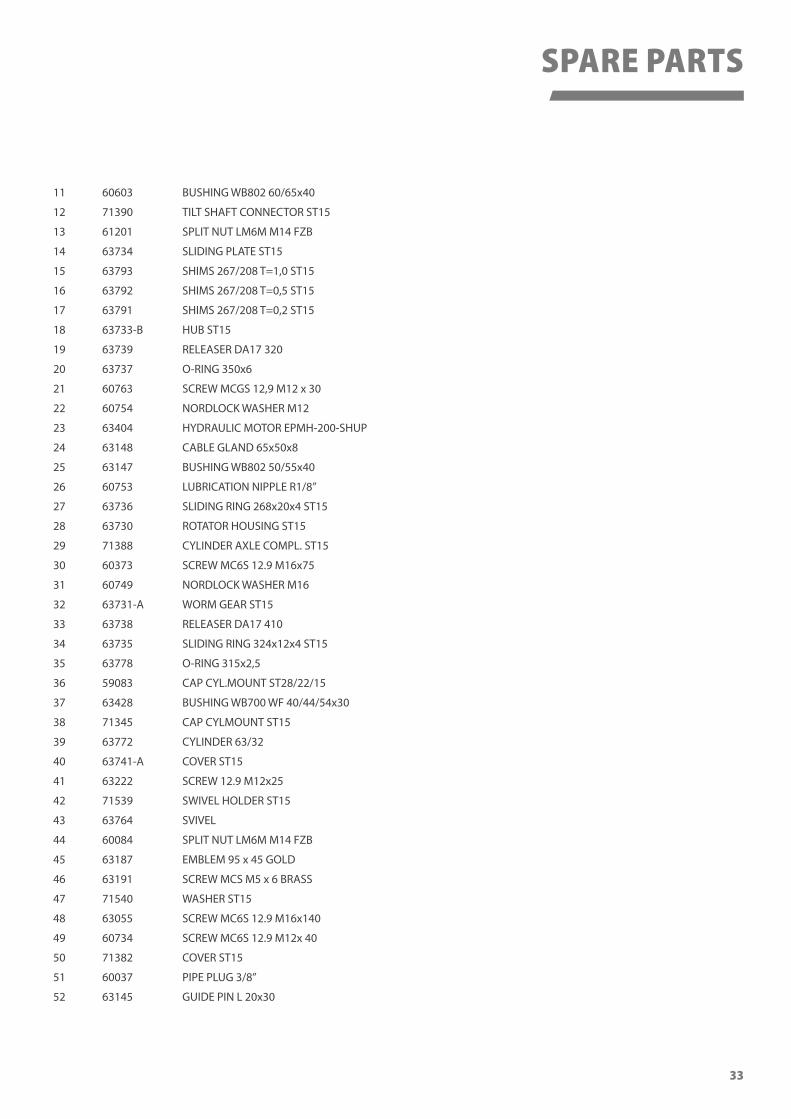
11 60603 BUSHING WB802 60/65x40
12 71390 TILT SHAFT CONNECTOR ST15
13 61201 SPLIT NUT LM6M M14 FZB
14 63734 SLIDING PLATE ST15
15 63793 SHIMS 267/208 T=1,0 ST15
16 63792 SHIMS 267/208 T=0,5 ST15
17 63791 SHIMS 267/208 T=0,2 ST15
18 63733-B HUB ST15
19 63739 RELEASER DA17 320
20 63737 O-RING 350x6
21 60763 SCREW MCGS 12,9 M12 x 30
22 60754 NORDLOCK WASHER M12
23 63404 HYDRAULIC MOTOR EPMH-200-SHUP
24 63148 CABLE GLAND 65x50x8
25 63147 BUSHING WB802 50/55x40
26 60753 LUBRICATION NIPPLE R1/8”
27 63736 SLIDING RING 268x20x4 ST15
28 63730 ROTATOR HOUSING ST15
29 71388 CYLINDER AXLE COMPL. ST15
30 60373 SCREW MC6S 12.9 M16x75
31 60749 NORDLOCK WASHER M16
32 63731-A WORM GEAR ST15
33 63738 RELEASER DA17 410
34 63735 SLIDING RING 324x12x4 ST15
35 63778 O-RING 315x2,5
36 59083 CAP CYL.MOUNT ST28/22/15
37 63428 BUSHING WB700 WF 40/44/54x30
38 71345 CAP CYLMOUNT ST15
39 63772 CYLINDER 63/32
40 63741-A COVER ST15
41 63222 SCREW 12.9 M12x25
42 71539 SWIVEL HOLDER ST15
43 63764 SVIVEL
44 60084 SPLIT NUT LM6M M14 FZB
45 63187 EMBLEM 95 x 45 GOLD
46 63191 SCREW MCS M5 x 6 BRASS
47 71540 WASHER ST15
48 63055 SCREW MC6S 12.9 M16x140
49 60734 SCREW MC6S 12.9 M12x 40
50 71382 COVER ST15
51 60037 PIPE PLUG 3/8”
52 63145 GUIDE PIN L 20x30
SPARE PARTS
34
1312
9
15
7&
5
&
144&47
21
48
4
1&
45
4342
41
40
2239
34
19
18
17 20
2221
23
2425
2&
1&
28
2722
29
2&30
3231
93
3344
353&
3722
38
50
51
49
22
21
1110
8
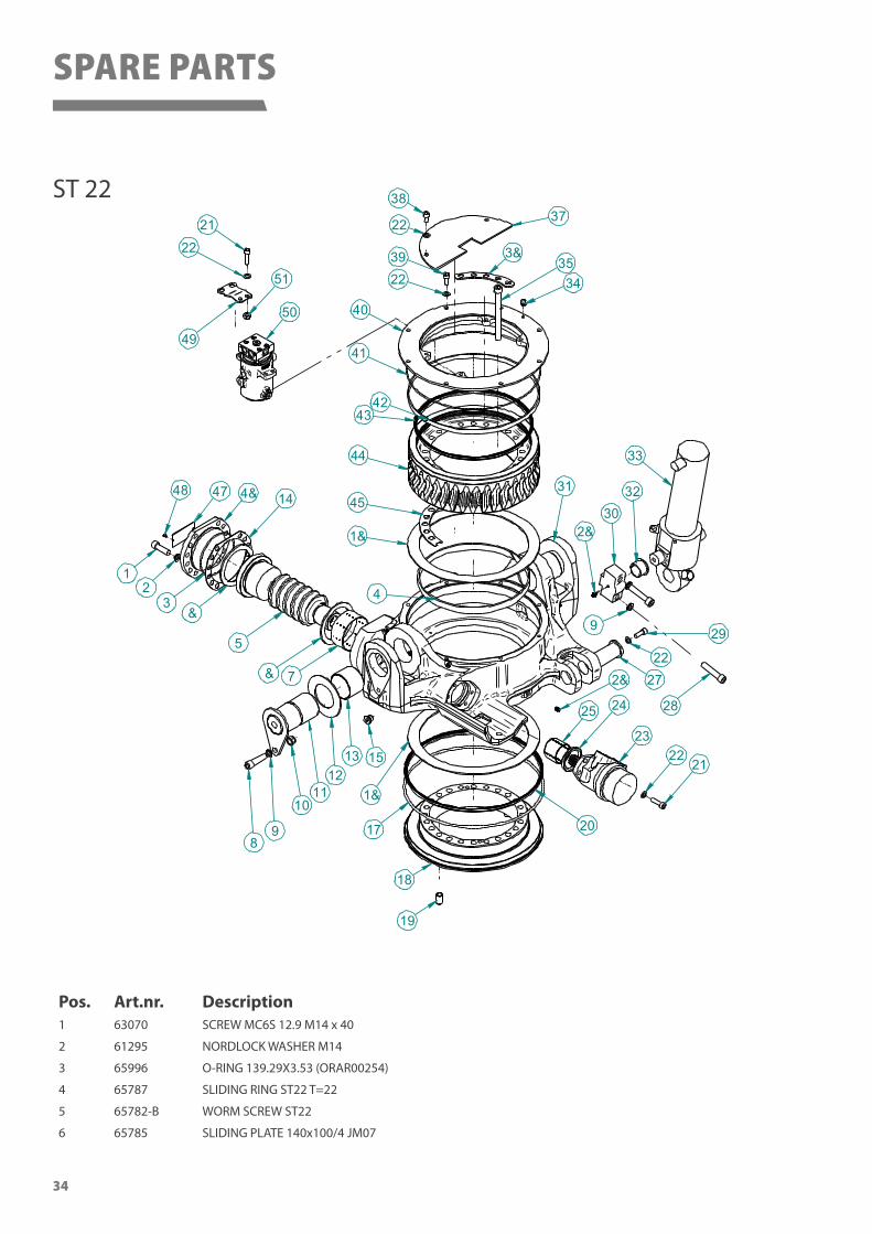
Pos. Art.nr. Description1 63070 SCREW MC6S 12.9 M14 x 40
2 61295 NORDLOCK WASHER M14
3 65996 O-RING 139.29X3.53 (ORAR00254)
4 65787 SLIDING RING ST22 T=22
5 65782-B WORM SCREW ST22
6 65785 SLIDING PLATE 140x100/4 JM07
ST 22
SPARE PARTS
35
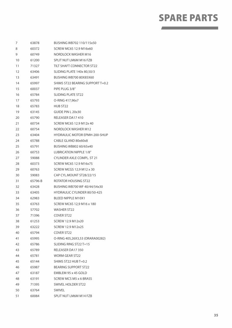
7 63878 BUSHING WB702 110/115x50
8 60372 SCREW MC6S 12.9 M16x60
9 60749 NORDLOCK WASHER M16
10 61200 SPLIT NUT LM6M M16 FZB
11 71327 TILT SHAFT CONNECTOR ST22
12 63406 SLIDING PLATE 140x 80,50/3
13 63491 BUSHING WB700 80X85X60
14 65997 SHIMS ST22 BEARING SUPPORT T=0.2
15 60037 PIPE PLUG 3/8”
16 65784 SLIDING PLATE ST22
17 65793 O-RING 417,96x7
18 65783 HUB ST22
19 63145 GUIDE PIN L 20x30
20 65790 RELEASER DA17 410
21 60734 SCREW MC6S 12.9 M12x 40
22 60754 NORDLOCK WASHER M12
23 63404 HYDRAULIC MOTOR EPMH-200-SHUP
24 65788 CABLE GLAND 80x60x8
25 65791 BUSHING WB802 60/65x40
26 60753 LUBRICATION NIPPLE 1/8”
27 59088 CYLINDER AXLE COMPL. ST 21
28 60373 SCREW MC6S 12.9 M16x75
29 60763 SCREW MCGS 12,9 M12 x 30
30 59083 CAP CYL.MOUNT ST28/22/15
31 65796-B ROTATOR HOUSING ST22
32 63428 BUSHING WB700 WF 40/44/54x30
33 63405 HYDRAULIC CYLINDER 80/50-425
34 62983 BLEED NIPPLE M10X1
35 63763 SCREW MC6S 12,9 M16 x 180
36 57702 WASHER ST22
37 71396 COVER ST22
38 61253 SCREW 12.9 M12x20
39 63222 SCREW 12.9 M12x25
40 65794 COVER ST22
41 65995 O-RING 405,26X3,53 (ORARA00282)
42 65786 SLIDING RING ST22 T=15
43 65789 RELEASER DA17 350
44 65781 WORM GEAR ST22
45 65144 SHIMS ST22 HUB T=0.2
46 65987 BEARING SUPPORT ST22
47 63187 EMBLEM 95 x 45 GOLD
48 63191 SCREW MCS M5 x 6 BRASS
49 71395 SWIVEL HOLDER ST22
50 63764 SWIVEL
51 60084 SPLIT NUT LM6M M14 FZB
SPARE PARTS
36
25
21
43
44
7
54
3
2
1
2829
109 23
2221
19
18
1716
15
26
20
67
50
49
8
14
6
5152
21
22
34
35
36
37
38
39
4041
42
48
46
45
47
2728 29
30
10
3233
2
31
24
1112
13
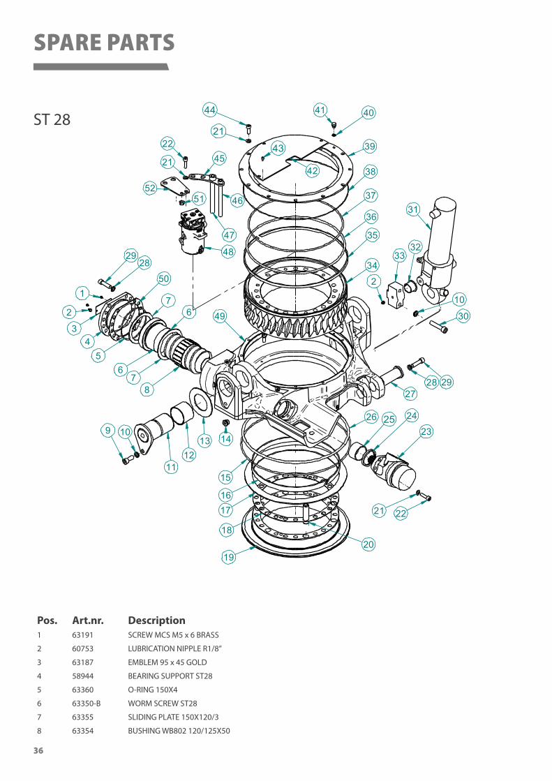
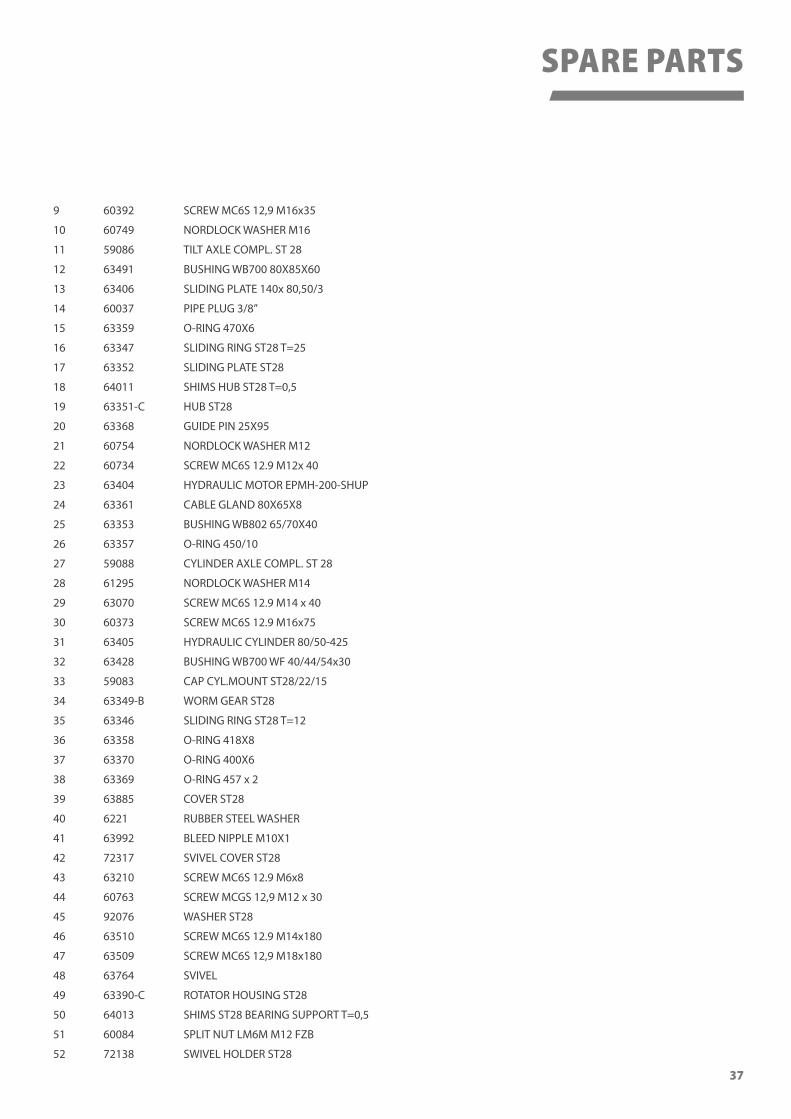
Pos. Art.nr. Description1 63191 SCREW MCS M5 x 6 BRASS
2 60753 LUBRICATION NIPPLE R1/8”
3 63187 EMBLEM 95 x 45 GOLD
4 58944 BEARING SUPPORT ST28
5 63360 O-RING 150X4
6 63350-B WORM SCREW ST28
7 63355 SLIDING PLATE 150X120/3
8 63354 BUSHING WB802 120/125X50
ST 28
SPARE PARTS
37
9 60392 SCREW MC6S 12,9 M16x35
10 60749 NORDLOCK WASHER M16
11 59086 TILT AXLE COMPL. ST 28
12 63491 BUSHING WB700 80X85X60
13 63406 SLIDING PLATE 140x 80,50/3
14 60037 PIPE PLUG 3/8”
15 63359 O-RING 470X6
16 63347 SLIDING RING ST28 T=25
17 63352 SLIDING PLATE ST28
18 64011 SHIMS HUB ST28 T=0,5
19 63351-C HUB ST28
20 63368 GUIDE PIN 25X95
21 60754 NORDLOCK WASHER M12
22 60734 SCREW MC6S 12.9 M12x 40
23 63404 HYDRAULIC MOTOR EPMH-200-SHUP
24 63361 CABLE GLAND 80X65X8
25 63353 BUSHING WB802 65/70X40
26 63357 O-RING 450/10
27 59088 CYLINDER AXLE COMPL. ST 28
28 61295 NORDLOCK WASHER M14
29 63070 SCREW MC6S 12.9 M14 x 40
30 60373 SCREW MC6S 12.9 M16x75
31 63405 HYDRAULIC CYLINDER 80/50-425
32 63428 BUSHING WB700 WF 40/44/54x30
33 59083 CAP CYL.MOUNT ST28/22/15
34 63349-B WORM GEAR ST28
35 63346 SLIDING RING ST28 T=12
36 63358 O-RING 418X8
37 63370 O-RING 400X6
38 63369 O-RING 457 x 2
39 63885 COVER ST28
40 6221 RUBBER STEEL WASHER
41 63992 BLEED NIPPLE M10X1
42 72317 SVIVEL COVER ST28
43 63210 SCREW MC6S 12.9 M6x8
44 60763 SCREW MCGS 12,9 M12 x 30
45 92076 WASHER ST28
46 63510 SCREW MC6S 12.9 M14x180
47 63509 SCREW MC6S 12,9 M18x180
48 63764 SVIVEL
49 63390-C ROTATOR HOUSING ST28
50 64013 SHIMS ST28 BEARING SUPPORT T=0,5
51 60084 SPLIT NUT LM6M M12 FZB
52 72138 SWIVEL HOLDER ST28
SPARE PARTS

About SMP Parts
SMP is a leading designer and manufacturer of high quality equipment and tools for excavators and backhoe
loaders. Our company prides itself on producing products and solutions that are of the highest quality and
safety standards. We are a very customer focused company and by adapting our products, we can modify the
solution for each customer’s specific challenge or task at hand.
Since 1980 SMP Parts has been developing and producing equipment for mini excavators, tractor loaders
and wheel drive/track drive excavators. Some of the products we offer are quick couplers, excavator
buckets, grading buckets and a range of other accessories.
SMP’s own patented quick hitch was launched in 1983 and in 1985 the Swingotilt® tiltrotator was
developed.
In 1987 the AREMA GROUP AB took over the company and in 1989 SMP began selling to the
Norwegian market.
In 1992 all manufacturing was moved to the present site in Ilsbo, Sweden and a year later a
sales office in Germany opened.
SMP Parts have over 100 employees, most of which work at the factory in Ilsbo, Sweden
but we also have employees in Norway and Germany.
SMP Parts operates in Sweden, Norway, Finland, Denmark, Germany, England, Spain
and the Benelux countries, with a number of dealers in each country. All development
and manufacturing is carried out in the main headquarters and factory in Sweden.
To meet the requirements of quality, function and finish, SMP has over the years
invested in a modern and efficient fleet.
Headquarters / factory
SMP Parts ABBergsjövägen 3, SE-820 71 Ilsbo, SwedenTel: +46 650 356 50, Fax: +46 650 [email protected]
Download a digital copy of this manual
Tilt
rota
tor U
ser M
anua
l 671
84-E
N R
EV20
15-1
2