SMLC Products Catalog - INMOCO · SMLC Products Catalog ... instruction list and structured text....
44
SMLC Products Catalog ServoWire ® Motion & Logic Controller Firewire-based Servodrive Networking Integrated Control Hardware I/O Solutions Table of Contents Page SMLC Product Overview............................. 2 SMLC Model 30, 80 160 .......................... 4 SMLC-SA (Single Axis Controller/Drive).... 6 CoDeSys Development Software .............. 8 HMI Touchscreens ..................................... 12 Machine I/O ............................................. 14 Ethernet & Profibus Networking Solutions ................................. 17 ServoWire Pro .......................................... 18 ServoWire SD Drives ....... ....................... 20 230 Series ......................................... 22 460 Series ............................................ 24 LP (Low Power) Drive ............................... 26 Servomotors ............................................. 28 Pacer Encoders ........................................ 43 Contact Information........................Back Cover HMIs Motion and logic. All in one. Now you can combine the best of both worlds with IEC 61131-3 programming tools and powerful motion control software for up to 16 axes. ORMEC’s ServoWire Motion & Logic Controller (SMLC) product family provides integrated, cost- effective control that leverages industry-standard hardware and software solutions. Reduce your software development and support costs using the common “look and feel” of our CoDeSys software solution for programming applications using sequential function chart, relay ladder logic, function block diagrams, instruction list and structured text. Utilize the PLCopen motion control library plus powerful ORMEC extensions for electronic gearing, camming, registration control, superimposed motion and coordinated, multi- axis applications. Also, check out our line-up of Firewire- based digital drives and servomotors, plus solutions for machine I/O, factory networking and HMI. IEC 61131-3 programming and high performance motion for up to 16 axes in a simple, cost-effective package.
Transcript of SMLC Products Catalog - INMOCO · SMLC Products Catalog ... instruction list and structured text....
SMLC Products Catalog
ServoWire® Motion & Logic Controller
Firewire-based Servodrive Networking
Integrated Control HardwareI/O Solutions
Table of Contents Page
SMLC Product Overview............................. 2SMLC Model 30, 80 160 .......................... 4SMLC-SA (Single Axis Controller/Drive).... 6CoDeSys Development Software .............. 8HMI Touchscreens ..................................... 12Machine I/O ............................................. 14
Ethernet & ProfibusNetworking Solutions ................................. 17ServoWire Pro .......................................... 18ServoWire SD Drives ....... ....................... 20
230 Series ......................................... 22460 Series ............................................ 24
LP (Low Power) Drive ............................... 26Servomotors ............................................. 28Pacer Encoders ........................................ 43Contact Information........................Back Cover
HMIs
Motion and logic. All in one. Nowyou can combine the best of bothworlds with IEC 61131-3programming tools andpowerful motion controlsoftware for up to 16 axes.
ORMEC’s ServoWireMotion & Logic Controller(SMLC) product familyprovides integrated, cost-effective control that leveragesindustry-standard hardware andsoftware solutions.
Reduce your software developmentand support costs using the common“look and feel” of our CoDeSys softwaresolution for programming applicationsusing sequential function chart, relayladder logic, function block diagrams,
instruction list and structuredtext. Utilize the PLCopen
motion control library pluspowerful ORMEC
extensions for electronicgearing, camming,registration control,
superimposed motionand coordinated, multi-
axis applications. Also, check out our line-up
of Firewire- based digitaldrives and
servomotors, plussolutions formachine I/O,factorynetworkingand HMI.
IEC 61131-3 programming and high performance motionfor up to 16 axes in a simple, cost-effective package.

Fully integrated total systems solutions ...
IntegratedControlHardware
ORMEC -2- SMLC PRODUCTS OVERVIEW
Quality AC brushless servomotors offer continuousstall torques from 3 to 665 lb-in (0.32-75 N-m).
Up to 16 servos can be daisy-chainedand interfaced to the SMLC usingstandard IEEE-1394b network interfaceand cabling.
Machine I/O solutionsinclude Ethernet orProfibus DP.
The ServoWire® Motion and Logic Controller is acost-effective control platform offering rugged,industrial hardware, a proven RTOS and industrystandard networking, programmed using standardIEC 61131-3 languages. An SMLC system offerslow cost, compact, proven and reliablecomponents.
✔ Featuring Pentium-class processors.✔ Two built-in Ethernet ports, two FireWire
ports, three or four serial ports.✔ Compact Flash program storage (eliminates
hard disk) and 32k battery-backed SRAM datastorage.
✔ Reliable, QNX real-time operating system.See page 4 for more information on controllers.
Firewire motion networking reduces cost & complexity✔ Control one to 16 servos directly from one controller
without specialized motion control hardware.✔ ServoWire® SD drives offer a power range from 200 to
24,000 watts, continuous output currents from 2.4 to60 amps RMS/phase with input voltages including 24-96 VDC, 115/230 VAC, and 460 VAC.
See page 20 for more information on ServoWire Drives.
Conveniently interface a variety of servos✔ Mix and match servo technologies (DC brushless
rotary, linear, DC brush-type or voice coil motors) inthe same drive hardware.
✔ Continuous stall torques from 3 to 665 lb-in (0.32-75N-m).
See page 28 for more information on AC Brushless Servomotors
IEC 61131-3 programming and high performance motion for up to 16 axes in a single package.

Solutions for I/O Needs
HMI Touchscreens
CoDeSys Development Software
Conserve panel space by utilizing Modbus/TCP(Ethernet) or Profibus DP to connect up to 512 I/O perbus coupler and thousands of I/O points.
See page 15 for more information.
Cost-effective, standalone touchscreen HMIs utilizeModbus RTU (Serial) or Modbus/TCP (Ethernet)communications. Or you can utilize Windows-basedHMIs such as Wonderware InTouch, Rockwell AutomationRS View, Intellution iFIX, CiTect or GE Cimplicity thatcommunicate with the SMLC using an OPC Server. Seepage 13 for more information.
ORMEC -3- SMLC PRODUCTS OVERVIEW
Utilizing industry-standard IEC 61131-3, you can developmotion and I/O programming using standard tools thatstreamline development and create applicationprograms that are both more effective and easier tosupport in the field. See page 8 for more information.
✔ Select among text-based and graphical languagesto pick the right one for the job -- Relay LadderLogic, Function Block Diagram, Structured Text,Instruction List or Sequential Function Chartprogramming.
✔ Program motioncontrol and logicusing standard IEC61131-3 tools.
✔ Suite of programminglanguages anddiagnostic toolsstreamlines machinedevelopment andsimplifies support.
✔ PLCopen standardMotion ControlLibrary, plus powerfulORMEC extensions,bring new levels ofmotion performancefor electronic gearing,camming, registrationcontrol andcoordinated, multi-axis applications.
ServoWire® Motion & Logic Controller - Models 30, 80, 160
SMLC
ORMEC -4- SMLC
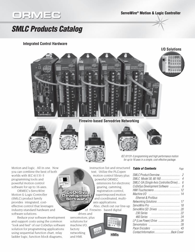
ORMEC’s ServoWire Motion & LogicController (SMLC) is at the center of acomplete machine control solution thatcan meet all of your motion, I/O andnetworking needs. By combiningPentium processors, IEEE 1394bFireWire drive networking and Ethernetconnectivity, the SMLC is a system thatcan control your entire machine. Thisallows you to focus on solving yourapplication instead of integratingcontrol components.
The SMLC, ServoWire Drive Networkand Modbus/TCP provide state-of-the-art I/O and motion control (for up to 16axes), all programmed using any of thefive IEC 61131-3 standard languagesincluding relay ladder logic.
SMLC Controllers The ServoWire Motion & LogicController (SMLC) features highperformance computing capabilitycombined with a true real-timeoperating system (RTOS). Using theindustry standard family of Intel 32-bitprocessors running the QNX RTOSprovides plenty of cost effective, robustcomputing power for even the mostdemanding multi-axis motion and I/Ocontrol applications.
Machine I/O The SMLC provides a multi-tiered,flexible approach to meeting machineI/O requirements. It has the ability tointerface high-speed drive based I/O formicrosecond position capture andsingle servo update response to sensorsignals. It also provides sub-millisecond programmable limit switchoutputs that are tightly coupled to themotion control. General purpose I/O options are fullysupported using WAGO 750 SeriesEthernet I/O as well as optionalProfibus DP Master support. In eithercase, a wide variety of analog anddigital I/O modules can be costeffectively connected to and controlledby the SMLC.
ServoWire Drive Network ORMEC’s AC brushless servomotorsand ServoWire digital servodrives offertested and guaranteed performancewith the SMLC. The result is maximumperformance from a tightly integrated,pre-engineered package that simplifieseverything from system integration tomaintenance. Fully digital control offerscompelling benefits—eliminatingmanual servodrive setup and providingreal-time software access to allparameters. In an SMLC system, theposition, velocity and torque loops areall closed by the digital signalprocessors (DSPs) in the ServoWireDrives based on position commandssent from the SMLC. Velocity observersoftware eliminates the need for analogtachometers, and potentiometers areeliminated since all gain andcompensation parameters are set insoftware. All loop adjustments areautomatically computed when a motorand its load inertia are specified inServoWire Pro—greatly simplifyingservo system tuning.
SMLC Controller1. Processor Options
Intel architecture microprocessor128 Mbytes DRAM128 Mbytes of FLASH memory for program storage32 Kbytes SRAM (battery packed) for non-volatile data storage
2. Communication PortsTwo IEEE 1394b ServoWire (FireWire) PortsTwo Ethernet Communication Ports.Three RS-232 Communication Connectors.
3. Input Power Supply 115/230 VAC input power (auto-ranging),
50/60 Hz +5, +/-12 VDC logic power output
4. Status LEDsEight status LEDs on the face for indicating system status.
SMLC — At A Glance✔ Powerful and Robust: Intel 32-bit
processors running the QNX RTOS.
✔ Compact Size: 2.75” x 7.2” x 9” (W xD x H) for Model 30 and 80 or 4.25” x7.2” x 9” for Model 160.
✔ IEC 61131-3 ApplicationProgramming: Internationalprogramming standard for PLCs.
✔ PLCopen Motion Blocks: Standardcompliant motion blocks, powerfulORMEC enhancements.
✔ ServoWire: High-bandwidth,synchronous, all-digital servodrivenetwork based on IEEE 1394b.
✔ Networking Options: Modbus/TCP,Ethernet/IP and OPC Server.
✔ I/O Options: WAGO 750 SeriesEthernet I/O, Profibus DP Master.

ORMEC -5- SMLC
Specifications
General Specifications
● Input Voltage: 115/230 VAC, 1.0/0.5A (+15%, -20%), 50/60 Hz
● Operating Temperature: 0 to 50C
● Relative Humidity: 10 to 95% @40C (non-condensing)
● Weight: Approx. 3.1/3.5 lbs
● Dimensions: 2.75” x 7.2” x 9.0”(69.9 x 182.9 x 228.6 mm), W x D xH for Model 30 & 80 or 4.25” x7.2” x 9.0” (108 x 182.9 x 228.6mm) for Model 160.
Processor & Memory● Main Processor: Industry
standard 32-bit Intelmicroprocessors
● DRAM: 128 Mbytes
● Program Memory: 128 Mbytes(Removable Compact Flash)
● Non-Volatile Memory: 32 Kbytes(battery backed).
Motion Control● All-digital control algorithms
featuring velocity and accelerationfeedforward for optimalperformance.
● Position Command Update Rates:1.0, 2.0, 2.66 kHz (axis countindependent).
● High-speed sensor inputs to initiatemotion within one positioncommand update.
● High-speed hardware positioncapture (<1 usec), ideal for use inhigh-speed registrationapplications.
● Software controlled position, speedand current (torque) limits.
● Drive fault protection circuits,watchdog timers and integrateddiagnostics for fail-safe operation.
● Full 32-bit position count or moduloposition in user units.
● SMLC Model 30 - 3 axesSMLC Model 80 - 8 axesSMLC Model 160 - 16 axes
8.45
2.75
0.58
2.08
9.00
0.10
1.35
2.85
0.001.501.50
Mounting hole .210 [5.3] dia.use 10-32 or M5 machinescrew. Qty 3.
An
alo
g I/
O
An
alo
gI/
O
VG
AC
OM
1
CO
M2
1394
KY
BD
Dig
ital
I/O
Eth
ern
etU
SB
1394
STA
TUS
Syst
em C
ard
yRS
T
VG
AC
OM
1
CO
M2
1394
KY
BD
Dig
ital
I/O
Eth
ern
etU
SB
1394
STA
TUS
Syst
em C
ard
yRS
T
CO
M3
CO
M4
CO
M3
+5
Dis
k
+5
Dis
k
0.0
4.2
All dimensions in inches.
SMLC-160 Mounting dimensions
2.1
0.0
SMLC-30, SMLC-80 Mounting dimensions
0.0
1.33
8.78
SMLC Mounting Diagrams
ORDERING GUIDESMLC Model 30, 80 & 160 Motion Controllers
SMLC-SMLC-SMLC-SMLC-SMLC- - -0
0 No Fieldbus adapterPM Profibus Master
30 SMLC Model 30, 115/230 VAC,3 axis unit3 axis unit3 axis unit3 axis unit3 axis unit, two Firewire ports(IEEE 1394b), two Ethernet,three RS-232 interfaces andone PC104+ expansion slot.
80 SMLC Model 80, 115/230 VAC,8 axis unit8 axis unit8 axis unit8 axis unit8 axis unit, two Firewire ports(IEEE 1394b), two Ethernet,three RS-232 interfacesand one PC104+ expansion slot.
160 SMLC Model 160, 115/230 VAC,16 axis unit16 axis unit16 axis unit16 axis unit16 axis unit, two Firewire ports(IEEE 1394b), two Ethernet,fourfourfourfourfour RS-232 interfacesand twotwotwotwotwo PC104+ expansion slots.
PC/104+ cable
7.23
9.00
Side view all.
Inputs/Outputs● SMLC I/O: 8 inputs, 8 outputs, 1
analog in, 1 analog out.● General I/O: 64 modules per
Wago 750 Series bus coupler, upto 512 I/O points connected viaEthernet (Modbus/TCP).Multiple bus couplers can beused for additional I/O.
● Profibus DP Master (optional)supports up to 126 I/O nodes.
Communications● Standard: Three RS-232 serial
ports, four on Model 160.
● Standard: Two Ethernet 10/100baseT ports with RJ45connectors.

SMLC with Integrated Servo Drive
SMLC-SA
ORMEC -6- SMLC-SA
The SMLC-SA combines ORMEC’s high-performance drive technology with theIEC-61131-3 programming capabilities ofthe SMLC controller into a single,compact, cost-effective package.Standard PLCopen motion controlfunction blocks reduce your softwaredevelopment costs and powerful ORMECextensions make solving your toughestmotion applications a snap. Application-specific function blocks such asReciprocating Flying Shear and RotaryKnife are available to provide solutionsright out of the box.
A total of fourteen models cover an outputpower range from 600 watts to 24,000watts. The SA230 series offers eightmodels with continuous output currentsfrom 2.5 to 60 amps RMS/phase for 115 to230 VAC input. The SA460 series offers sixmodels with continuous output currentsfrom 5 to 50 amps RMS/phase for 230 to460 VAC input.
The SMLC-SA uses the same developmentand commissioning tools as the SMLCproduct line, providing seamlessscalability from one to sixteen axes. TheCoDeSys Integrated DevelopmentEnvironment (IDE) and runtime engineare world class IEC-61131-3 tools used inhundreds of products worldwide. Theseare robust, full-featured tools withextensive diagnostic capabilities.ServoWire Pro is an easy to use, integratedsuite of configuration, diagnostic andmaintenance utilities to assist in thecommissioning of the drive.
In addition to the built-in I/O there is acomplete line of networked I/O expansionmodules available based on Ethernet thatcan handle thousands of I/O points. HMIand factory networking support isprovided via built-in Modbus/TCP as wellas via the free OPC server.
KEY FEATURES
❒ Powerful enough to control your entire machine.❒ Program logic and motion using all five IEC 61131-3 languages.❒ Application-specific function blocks provide solutions right out of
the box.❒ Broad power range, 600 to 24,000 watts (30+ horsepower).❒ Broad input voltage range, 115 to 480 VAC.❒ High performance Intel processor.❒ Reliable, robust, QNX real-time operating system.❒ Industrial, all metal enclosure.❒ Removable program storage (compact Flash).❒ Built-in I/O: 27 digital and 4 analog, expandable to thousands.❒ Two Ethernet and two serial ports included.
The ServoWire Motion& Logic Controller -Single Axis (SMLC-SA) is a standard off-the-shelf, cost-effectivecontrol platform.Program motioncontrol and logic usingstandard IEC 61131-3tools. PLCopenstandard motion controlfunction blocks pluspowerful ORMECextensions reduce yoursoftware developmentcosts and bring newlevels of motionperformance to single-axis applications.

ORMEC -7- SMLC-SA
Features
Logic Controller32-bit microprocessorQNX RTOSIEC-61131-3 programmingPLCopen compliant motioncontrol function blocksAdditional ORMEC specificmotion control function blocksTwo Ethernet ports2 serial ports64Mb compact Flash basedprogram storage128Mb RAM32k battery backed SRAM for realtime non-volatile variablestorage
Built-in I/OThe SMLC-SA includes the following29 built-in I/O:
2 High Speed Sensor inputs12 Digital inputs, opticallyisolated13 Digital outputs, opticallyisolated1 14-bit Analog input (2ndoptional)1 14-bit Analog output (2ndoptional)
Network I/O OptionsYou can expand the SMLC-SA I/Ousing the following interface:
Wago 750 Series Ethernet I/O(Modbus/TCP)
Networking OptionsThe SMLC-SA includes the followingnetwork options that can be used forconnection to an HMI, anothermachine or to a factory network:
Modbus/TCP ServerOPC ServerEthernet/IP (Industrial Protocol)
SpecificationsMain Circuit PowerSMLC-SA203, 205, 210, 217, 220,225, 235, 260
115/230 VAC, +15%, -20%, 50/60 Hz
SMLC-SA405, 410, 417, 425, 435,450
230/480 VAC, +10%, -20%, 50/60 Hz
Control Circuit Power115/230 VAC,1.0/0.5A (+15%, -20%), 50/60 Hz, 56 Watts RMS,(230 VAC only on SMLC-SA435and 450 models)
Control Loop Update RatesPosition loop update rate: up to2.66KhzVelocity loop update rate: up to5kHzTorque loop update rate: 10kHz
EnvironmentalAmbient operating is 0 to 50CAmbient storage is –20 to 70CHumidity operating/storage is90% RH or less (non-condensing)
Other FeaturesDiagnostic LEDs for the controllerTwo digit display for drive statusUL/CE approvals: UL Listed and CEMark (low voltage directive & EMC)
Drive OutputIGBT pulse width-modulated withsinusoidal or trapezoidalcommutationInternal shunt regulator forregenerative load dissipation(except 203 and 205)Peak currents up to 200% of RMScontinuous capabilityCompatible w/ DC brushless rotary,linear, DC brush & voice coil motorsField Oriented Control (FOC) andSpace Vector Modulation (SVPWM)for optimal performance at allmotor speeds
Motor Feedback InterfaceEncoder or Resolver InterfaceQuadrature feedback 4x decodingwith data rates to 8 Mhz (afterdecode) and open wire detectionThree differential input channels formotor commutation feedbackSupport for Yaskawa Sigma II andTamagawa serial encoders.Pacer encoder input (optional)Industry Standard D-sub interfaceconnector (25-pin, Encoder/female;Resolver/male).
Drive I/OHigh speed sensor inputs aresoftware configurable for NPN orPNP output transistors, level oredge triggered response, onemicrosecond position capture andcan initiate motion within one servoloop update.Externally powered 5-24 VDC opto-isolated general purpose I/O
Dimensions (Approximate) in inches
Model Height Width DepthSMLC-SA203, SA205, SA210 9.0 4.2 8.3SMLC-SA217 9.0 5.4 8.3SMLC-SA220 9.0 5.5 8.3SMLC-SA225, SA235, SA260 12.0 8.6 8.45SMLC-SA405 11.0 6.1 8.3SMLC-SA410 11.0 6.2 8.3SMLC-SA417, SA425 12.0 8.6 8.45SMLC-SA435, SA450 14.0 9.6 9.45
ORDERING GUIDESMLC Model SA
SMLC-SA - 0SMLC-SA - 0SMLC-SA - 0SMLC-SA - 0SMLC-SA - 0
Pacer Support (optional)
P = add incrementalPacer supportO = no pacer support
Analog I/O (optional)A = Analog I/O includedO = option not included
Absolute Encoder Support (optional)B = add back-up Battery for absolute enc.0 = no battery added
Primary FeedbackS = Serial & Encoder Feedback InterfaceR = Resolver Feedback Interface
Maximum Continuous Current03 = 2.5 A rms/ph (115/230 VAC model)05 = 4.1 A rms/ph (115/230 VAC model)05 = 5 A rms/ph (460 VAC model)10 = 8.2 A rms/ph (115/230 VAC model)10 = 10 A rms/ph (460 VAC model)17 = 13.9 A rms/ph (115/230 VAC model)17 = 17 A rms/ph (460 VAC model)20 = 16.3 A rms/ph (115/230 VAC model)25 = 25 A rms/ph (both VAC models)35 = 35 A rms/ph (both VAC models)50 = 50 A rms/ph (460 VAC model)60 = 60 A rms/ph (115/230 VAC model)
Bus Voltage2 = 115/230 VAC4 = 460 VAC

Administrative MotionSingle Axis Multiple Axis Single Axis Multiple AxisPower CamTableSelect MoveAbsolute CamInReadStatus MoveRelative CamOutReadAxisError GearInReadParameter GearOutReadBoolParameter
MoveVelocity
WriteParameter
Home
WriteBoolParameter
Stop
ReadActualPosition
PositionProfile
ResetDigitalCamSwitch
CoDeSys Development Software
Programming tools simplify software developmentCoDeSys Development Tools
Program motion control and logic using standard IEC61131-3 toolsSuite of programming languages and charting toolsimplifies machine development and supportSelect among graphical and text-based languages --Relay Ladder Logic, Function Block Diagram, StructuredText, Instruction List, Sequential Function Chart orContinuous Function Chart
PLCopen Motion Control LibraryStandard library of motion functionblocks which cover all of theIEC 61131-3 languages.
ORMEC MotionControl Extensions
ServoWire Motion Blocksprovide enhancedfunctionality for highperformance electronicgearing and coordinatedmulti-axis control.Analog feedback control.Registration control.
Built-inNetworking Support
Standard networkingsolutions and support forEthernet, TCP/IP,Modbus/TCP, ProfibusDP and OPC server.Connectivity for motionand I/O control, HMIsand factory datanetworks.
ServoWire ProServoWire Setup: menus and software wizards tosimplify configuration of ServoWire SD drives.ServoWire Monitor: diagnostic utilities for monitoringdrive and network performance.ServoWire Tune: tuning scope optimizes performance.ServoWire Upgrade: tools for maintaining new firmware.
Developing motion control and I/Oprogramming using a standard set ofsoftware tools streamlines softwaredevelopment and creates applicationprograms that are more effective andeasier to support in the field.
The CoDeSys DevelopmentSoftware utilizes standard IEC 61131-3programming and PLCopen motionfunction blocks to provide proven,open standard tools for developingapplication programs for motioncontrol and I/O control -- running on asingle controller.
IEC 61131-3 ProgrammingThe key advantage of IEC 61131-3
is that it provides an integrated set ofsoftware tools and graphical interfaces tomeet a wide range of softwaredevelopment needs:
✔ Relay Ladder Logic (LD)✔ Structured Text (ST)✔ Sequential Function Chart (SFC)✔ Function Block Diagram (FBD)✔ Instruction List (IL)
Developing application programsusing IEC 61131-3 offers the followingadvantages:
✔ Reduces training costs bylearning one set of programminglanguages used by multiplecontrol vendors.
✔ Provides flexibility for selectingthe best programming approach
CoDeSys Development Software
ORMEC -8- CODESYS DEVELOPMENT SOFTWARE
ORMEC -9- CODESYS DEVELOPMENT SOFTWARE
and methods for specificapplication tasks andrequirements.
✔ Offers the ability for theprogrammer to develop anddeploy reusable functionblocks which can reducefuture software developmentcosts and protect yourcompany’s intellectualproperty.
PLCopen Motion Control LibraryPLCopen is an independent,
worldwide association promotingIEC 61131-3 that has definedstandard motion programmingfunction blocks which cover all theIEC 61131-3 programminglanguages.
ORMEC’s motion programmingimplementation (ServoWire MotionBlocks) conforms to the PLCopenmotion block definitions andprovides powerful, flexiblefunctionality beyond that defined inthe standard. Using the ServoWireMotion Blocks, a variety ofapplications can be written in any ofthe IEC 61131-3 programminglanguages.
The ServoWire Motion Blocksprovide the following enhancedfunctionality:
✔ Move Relative At Velocity✔ Move Relative In Time✔ Move Absolute At Velocity✔ Move Absolute In Time✔ Gear Relative At Ratio✔ Gear Relative In Master
Distance✔ Cam Relative✔ Plus administrative function
blocks including enhanceddiagnostic capabilities
Move Relative and Gear Relativemotions can also be “superimposed”on a Gear In motion-- ideal foradjusting the phasing of a slave axisrelative to the master position axis,as in flying shear, rotary knife andregistered labeling applications.
ServoWire Motion Blocks can beinserted into relay ladder logic orfunction block diagrams tocoordinate motion with I/O updates.Optional parameters allow motionsto be triggered at the positioncommand update rate using high-
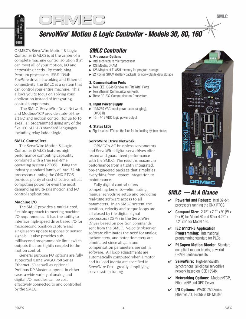
Using ServoWire motion blocks in ladder logic makes application software both simpler to develop and easier tosupport in the factory. Ladder logic provides a graphical, power flow for viewing program structure and execution.
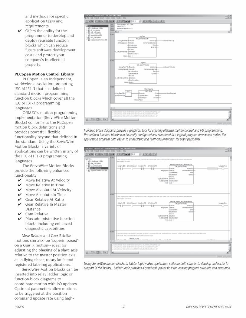
Function block diagrams provide a graphical tool for creating effective motion control and I/O programming.Pre-defined function blocks can be easily configured and combined in a logical program flow which makes theapplication program both easier to understand and “self-documenting” for plant personnel.

ORMEC -10- CODESYS DEVELOPMENT SOFTWARE
speed drive inputs, and automaticallyrepeated independent of, and fasterthan the I/O updates. This motioncommand flexibility allows an SMLCsystem to meet the high performancerequirements of demandingautomation applications.
IEC 61131-3 Development ToolsPowerful IEC 61131-3
development tools are provided forwriting, debugging and maintainingapplication programs. Thisdevelopment environment will assistyou in writing your applicationprogram by providing automaticvariable declaration, automatic codeformatting, syntax coloring andglobal search/replace functionality.There are tools for importing andexporting code modules, and aLibrary Manager for addingadditional system libraries to yourproject.
The Input Assistant identifiespossible entries for input variables,function calls and IEC keywords. Asimulation mode is available fortesting your program logic withoutneeding the controller and otherhardware.
To debug your application, awatch window is provided formonitoring and writing variablevalues, along with tools for settingreal-time program breakpoints --single stepping or single cyclingthrough the program. To monitoryour machine during operation, adigital storage scope provides cyclicor single-shot storage and candisplay up to eight programvariables.
The CoDeSys developmentenvironment provides tools forcreating visualizations which can beused to build operator entry anddiagnostic displays useful for testingand debugging the application.
When your application programis complete, all the source andsupporting files can be downloadedto the SMLC. Application programsource files can be passwordprotected to limit access toauthorized personnel only, and thecontroller acts as a storage mediumfor the application software, makingfield maintenance a snap.
SFC Editor
ORDERING GUIDECoDeSys Development Software
CDS-SDK/C CoDeSys Developers Kit, CD-ROM, incl. ServoWire Pro, serial cable andone year of maintenance & support (for all SMLC models)
CDS-SDK-SA/C CoDeSys Developers Kit, CD-ROM, incl. ServoWire Pro, serial cable andone year of maintenance & support (for SMLC-SA only)
CDS-SDK-MAINT CoDeSys SDK Annual Maintenance & Support Contract Renewal
Sequential Function Chart provides a graphical flow charting tool that illustrates the program flow and structureof the user’s application program. SFC makes it easy to view a multi-layered, graphical model of the programand provides excellent tools for application development and maintenance.
The Sampling Trace tool can be used to trigger and view eight program variables with up to 500 data points foreach variable. It is useful for application debugging, monitoring performance and capturing process information.

ORMEC -11- CODESYS DEVELOPMENT SOFTWARE
CoDeSys Programming ExampleProgramming languages and graphical tools work together to simplify software development
A key strength of the CoDeSys developmentenvironment is the different types of graphicaland text-based programming tools it provides fora particular job -- simplifying both the softwaredevelopment process and support of the machineby engineering and plant personnel.
1 -- Sequential Function Chart provides an excellenttool for illustrating program flow and structure.SFC simplifies viewing and understanding thesoftware modules in the application program.
2 -- By writing your program as a state machine in SFC, eachindividual state can contain only a few rungs of LadderLogic. Instead of hundreds or thousands of continguouslines of ladder logic programming, this structuredapproach makes programs easier to develop, understandand maintain. 4 -- Embedding function
blocks in laddersprogramming makessoftware easier tosupport in the factory.
3 -- Structured text programming is easily integrated into the programming structureand flow, simplifying development and support. CoDeSys support for a variety ofprogramming techniques provides a range of effective tools for creating powerfulyet manageable application programs.
HMI Touchscreens
HMI Touchscreens
ORMEC -12- HMI Touchscreens
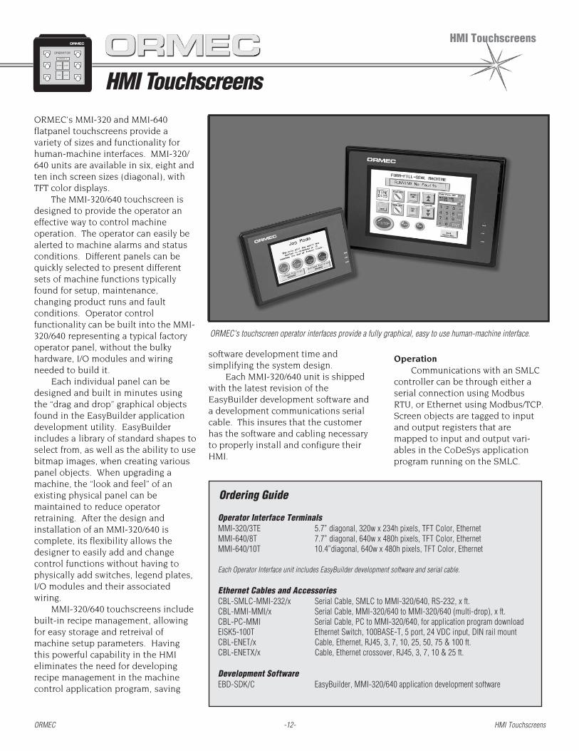
ORMEC’s MMI-320 and MMI-640flatpanel touchscreens provide avariety of sizes and functionality forhuman-machine interfaces. MMI-320/640 units are available in six, eight andten inch screen sizes (diagonal), withTFT color displays.
The MMI-320/640 touchscreen isdesigned to provide the operator aneffective way to control machineoperation. The operator can easily bealerted to machine alarms and statusconditions. Different panels can bequickly selected to present differentsets of machine functions typicallyfound for setup, maintenance,changing product runs and faultconditions. Operator controlfunctionality can be built into the MMI-320/640 representing a typical factoryoperator panel, without the bulkyhardware, I/O modules and wiringneeded to build it.
Each individual panel can bedesigned and built in minutes usingthe “drag and drop” graphical objectsfound in the EasyBuilder applicationdevelopment utility. EasyBuilderincludes a library of standard shapes toselect from, as well as the ability to usebitmap images, when creating variouspanel objects. When upgrading amachine, the “look and feel” of anexisting physical panel can bemaintained to reduce operatorretraining. After the design andinstallation of an MMI-320/640 iscomplete, its flexibility allows thedesigner to easily add and changecontrol functions without having tophysically add switches, legend plates,I/O modules and their associatedwiring.
MMI-320/640 touchscreens includebuilt-in recipe management, allowingfor easy storage and retreival ofmachine setup parameters. Havingthis powerful capability in the HMIeliminates the need for developingrecipe management in the machinecontrol application program, saving
Operator Interface TerminalsMMI-320/3TE 5.7” diagonal, 320w x 234h pixels, TFT Color, EthernetMMI-640/8T 7.7” diagonal, 640w x 480h pixels, TFT Color, EthernetMMI-640/10T 10.4”diagonal, 640w x 480h pixels, TFT Color, Ethernet
Each Operator Interface unit includes EasyBuilder development software and serial cable.
Ethernet Cables and AccessoriesCBL-SMLC-MMI-232/x Serial Cable, SMLC to MMI-320/640, RS-232, x ft.CBL-MMI-MMI/x Serial Cable, MMI-320/640 to MMI-320/640 (multi-drop), x ft.CBL-PC-MMI Serial Cable, PC to MMI-320/640, for application program downloadEISK5-100T Ethernet Switch, 100BASE-T, 5 port, 24 VDC input, DIN rail mountCBL-ENET/x Cable, Ethernet, RJ45, 3, 7, 10, 25, 50, 75 & 100 ft.CBL-ENETX/x Cable, Ethernet crossover, RJ45, 3, 7, 10 & 25 ft.
Development SoftwareEBD-SDK/C EasyBuilder, MMI-320/640 application development software
ORMEC's touchscreen operator interfaces provide a fully graphical, easy to use human-machine interface.
software development time andsimplifying the system design.
Each MMI-320/640 unit is shippedwith the latest revision of theEasyBuilder development software anda development communications serialcable. This insures that the customerhas the software and cabling necessaryto properly install and configure theirHMI.
OperationCommunications with an SMLC
controller can be through either aserial connection using ModbusRTU, or Ethernet using Modbus/TCP.Screen objects are tagged to inputand output registers that aremapped to input and output vari-ables in the CoDeSys applicationprogram running on the SMLC.
Ordering Guide

ORMEC -13- HMI Touchscreens
Touching a screen object, or enteringdata, sets the state of the variables inthe SMLC application program. Howthe change of state is used in theprogram defines the object’s controlfunction.
Graphical Panel Objects ❒ Pilot Light (Bit Lamp) ❒ Word Lamp ❒ Force Coil (Set Bit) ❒ Write Register (Set Word) ❒ Toggle Switch ❒ Multi-State Switch ❒ Function Key ❒ Numeric Input ❒ Numeric Display ❒ ASCII Data ❒ ASCII Display ❒ Moving Shape ❒ Animation ❒ Indirect Window ❒ Direct Window ❒ Alarm Display ❒ Trend Display ❒ XY Plot ❒ Bar Graph ❒ Meter Display ❒ Alarm Bar ❒ Recipe Upload/Download ❒ Event Display
Mounting & SealingHMI-320/640 units are cabinet
mounted, and feature a gasket and fouror six mounting brackets to maintain aNEMA 4 rating.
LED IndicatorsEach HMI-320/640 unit has three
status indicator LEDs to assist withinstallation and troubleshooting.
Touch panel type ResistiveColor Type
TFT TFT 256 colorTouch Resolution
6 inch 320W x 234H pixels8 and 10 inch 640W x 480H pixels
InstallationAll sizes Cabinet Mount
Vibration 10 to 25Hz 2Gs on eachx,y, z plane for 30 min.
TemperatureOperating 0C to 45CStorage -10C to 60C
Relative HumidityOperating 10% to 90% non-condensingStorage 5% to 85% non-condensing
Enclosure RatingsNEMA 4/IP65 front panel (O-ring seals).
General SpecificationsWeight
MMI-640/10T 4.4 lbs (2.0 kg)MMI-640/8T 2.6 lbs (1.2 kg)MMI-320/3TE 1.8 lbs (0.8 kg)
Input Power21-25 Volt DC @ 700mA
CEComplies with EN50081-2 and EN50082-2standards
EMIComplies with FCC Class A
Cabinet Mounted Unit Dimensions
Over
all
Mou
ntin
g &
Cut
out
Dimension MMI-320/3TE MMI-640/8T MMI-640/10T
G 5.7” 7.7” 10.4”145 mm 196 mm 264 mm
H1 5.43” 6.57” 8.86”138 mm 167 mm 225 mm
W1 7.56” 8.75” 11.89”192 mm 222 mm 302 mm
D1 2.55” 1.17” 2.04”65 mm 30 mm 52 mm
H2 5.9” 6.93” 9.37”150 mm 176 mm 238 mm
W2 8.0” 9.09” 12.4”203 mm 231 mm 315 mm
D2 2.95” 1.57” 2.44”75 mm 55 mm 62 mm
PWR - Indicates the unit has power.CPU - Indicates that the processor
is operating properly.COM - Flashes during serial
communications.CE Mark
All HMI-320/640 units are CEMarked, indicating compliance withEuropean Union directives EN 55011:Group 1, Class A; EN50081-2 (Also USFCC Class A) and EN50082-2.
D2
W1
H1
GH2
W2
D1
ORMEC

Machine I/O
Machine I/O
ORMEC -14- Machine I/O
WAGO Ethernet and Profibus DP I/Ofeature a wide variety of analog anddigital I/O modules that reliablyinterface the ServoWire Motion & LogicController (SMLC) to industrial devicessuch as switches, sensors, solenoids,valves and motor starters.
WAGO I/O utilizes either aEthernet or Profibus DP FieldbusCoupler for each node, which isconnected to DIN rail mounted I/Omodules. The user can selectappropriate modules (AC In/Out, DC In/Out, sinking/sourcing, Analog current/voltage, etc.) for their specificapplication.
The WAGO Fieldbus Couplers arecompact, flexible, high-performanceprocessors that provide the interfacebetween the I/O modules and either aProfibus DP or dedicated Ethernetnetwork. DIN rail mounted modulesprovide an efficient method formounting that minimizes panel space.
The 24 VDC digital input modulesinclude built-in noise filters, availablewith either a 3.0 or 0.2 msec timeconstant. The AC digital outputmodules utilize zero voltage turn-onand zero current turn-off of the load togreatly reduce generated EMI and RFI,and feature an internal dv/dt snubbernetwork for protection from voltagetransients on the line. All digital I/Omodules feature internal LEDindicators and digital output modulesinclude electronic short-circuitprotection.
The analog input modules areavailable with 12 or 16-bit resolution,and support a variety of input signalcurrent and voltage levels, including 0-20 mA, 4-20 mA, +/-10 V and 0-10V.Analog input modules are alsoavailable for use as interfaces tothermocouples, RTD sensors andresistor bridges. The analog outputmodules are 12-bit, and also support avariety of signal types.
Specialty modules are availablewith up/down counters, incremental
WWWWWAGO I/O: At a GlanceAGO I/O: At a GlanceAGO I/O: At a GlanceAGO I/O: At a GlanceAGO I/O: At a Glance✔✔✔✔✔ Standard Connectivity Solutions – WAGO Ethernet and Profibus DP I/O
provide standard connectivity solutions for interfacing digital andanalog I/O to the ServoWire Motion & Logic Controllers (SMLCs) that iseasy to implement, operate and maintain.
✔✔✔✔✔ Flexible Interface – All WAGO I/O modules connect to the SMLC usinga Fieldbus Coupler, one per rack. The Fieldbus Coupler interfaces tothe Ethernet or Profibus DP network providing a high-speed connectionto all I/O in the rack. I/O can be remotely distributed throughout themachine.
✔✔✔✔✔ Quick and Reliable Installation – Each module incorporates CAGECLAMP connection system for vibration-proof, fast and maintenance-free wiring with test points for easy access to signals with wiring inplace.
✔✔✔✔✔ Digital I/O Modules – WAGO I/O provides a full line of digital I/Omodules. DC inputs (5 & 24 VDC), DC outputs (5 & 24 VDC), AC inputs(80 to 230 VAC) and AC outputs (60 to 230 VAC) provide flexibleinterface options. Digital modules feature compact 2, 4 and 8 channeldesigns.
✔✔✔✔✔ Analog I/O Modules – Analog voltage inputs range from 0 to 10 volts,+/- 10 volts, and 4-20 mA. Analog output modules provide 0 to 10 volts,+/- 10 volts ranges. Analog input modules are available as efficient 2-channel devices. Interface to temperature sensors, load cells, dancercontrol systems, and other industrial analog voltage or current controlpoints.
✔✔✔✔✔ Minimum Panel Space – Compact 12 mm (0.47 in) and 24 mm (0.94 in)wide, DIN rail mounted module designs allow the OEM designer to usea minimum amount of panel space.
encoder interfaces, SSI interfaces andmore.
The I/O modules are color codedby function and provide a high degreeof isolation and noise immunitybetween the motion controller and
external components. Optionallabeling components are availableto clearly indicate I/O pointnumber, power and groundconnections for easier installationand maintenance.

ORMEC -15- Machine I/O
Ethernet I/O
ServoWire Motion &Logic Controller
Specs:✔ Data Rate: 10 Mbits/sec✔ Physical Media: CAT-5 cable, RJ-45 connector✔ Isolation: Transformer✔ Max Distance Node to Node: 100M✔ Max I/O Modules per Node: 64
Advantages:✔ Transformer isolation for noise immunity✔ Low cost industry standard cabling✔ Long distance between nodes and long total
network length✔ Optional industrial hubs and switches for various
network topologies
Profibus DP
ServoWire Motion &Logic Controller
Specs:✔ Data Rate: 12Mbaud (max) at 100M✔ Physical Media: Shielded twisted pair, 22 AWG✔ Isolation: None, RS-485✔ Max Distance Node to Node: 1200M at 93.75 kbaud
or lower (9500M total network with repeaters)✔ Max Number of Nodes: 96 (with repeaters)✔ Max I/O Modules per Node: 63
Advantages:✔ Long distances between nodes and long total
network length✔ Highly efficient data transmission, typically <1 msec/
node✔ In addition to WAGO I/O, Profibus DP interfaces are
available on a wide variety of devices, includingsensors, pneumatic manifolds, HMIs, etc.
Ethernet
I/O
I/O
(optional switch)
Profibus
ORMEC -16- Machine I/O
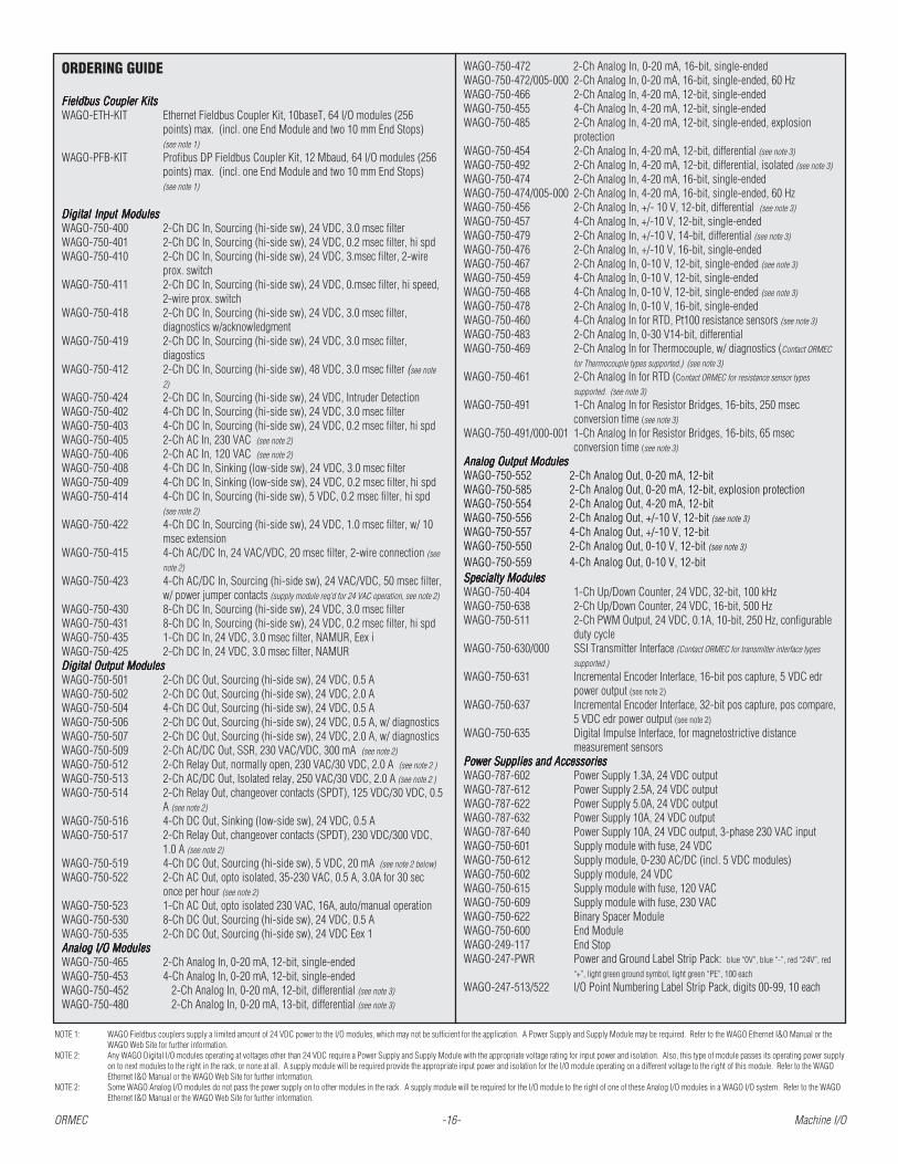
NOTE 1: WAGO Fieldbus couplers supply a limited amount of 24 VDC power to the I/O modules, which may not be sufficient for the application. A Power Supply and Supply Module may be required. Refer to the WAGO Ethernet I&O Manual or theWAGO Web Site for further information.
NOTE 2: Any WAGO Digital I/O modules operating at voltages other than 24 VDC require a Power Supply and Supply Module with the appropriate voltage rating for input power and isolation. Also, this type of module passes its operating power supplyon to next modules to the right in the rack, or none at all. A supply module will be required provide the appropriate input power and isolation for the I/O module operating on a different voltage to the right of this module. Refer to the WAGOEthernet I&O Manual or the WAGO Web Site for further information.
NOTE 2: Some WAGO Analog I/O modules do not pass the power supply on to other modules in the rack. A supply module will be required for the I/O module to the right of one of these Analog I/O modules in a WAGO I/O system. Refer to the WAGOEthernet I&O Manual or the WAGO Web Site for further information.
ORDERING GUIDE
Fieldbus Coupler KitsFieldbus Coupler KitsFieldbus Coupler KitsFieldbus Coupler KitsFieldbus Coupler KitsWAGO-ETH-KIT Ethernet Fieldbus Coupler Kit, 10baseT, 64 I/O modules (256
points) max. (incl. one End Module and two 10 mm End Stops)(see note 1)
WAGO-PFB-KIT Profibus DP Fieldbus Coupler Kit, 12 Mbaud, 64 I/O modules (256points) max. (incl. one End Module and two 10 mm End Stops)(see note 1)
Digital Input ModulesDigital Input ModulesDigital Input ModulesDigital Input ModulesDigital Input ModulesWAGO-750-400 2-Ch DC In, Sourcing (hi-side sw), 24 VDC, 3.0 msec filterWAGO-750-401 2-Ch DC In, Sourcing (hi-side sw), 24 VDC, 0.2 msec filter, hi spdWAGO-750-410 2-Ch DC In, Sourcing (hi-side sw), 24 VDC, 3.msec filter, 2-wire
prox. switchWAGO-750-411 2-Ch DC In, Sourcing (hi-side sw), 24 VDC, 0.msec filter, hi speed,
2-wire prox. switchWAGO-750-418 2-Ch DC In, Sourcing (hi-side sw), 24 VDC, 3.0 msec filter,
diagnostics w/acknowledgmentWAGO-750-419 2-Ch DC In, Sourcing (hi-side sw), 24 VDC, 3.0 msec filter,
diagosticsWAGO-750-412 2-Ch DC In, Sourcing (hi-side sw), 48 VDC, 3.0 msec filter (see note
2)
WAGO-750-424 2-Ch DC In, Sourcing (hi-side sw), 24 VDC, Intruder DetectionWAGO-750-402 4-Ch DC In, Sourcing (hi-side sw), 24 VDC, 3.0 msec filterWAGO-750-403 4-Ch DC In, Sourcing (hi-side sw), 24 VDC, 0.2 msec filter, hi spdWAGO-750-405 2-Ch AC In, 230 VAC (see note 2)
WAGO-750-406 2-Ch AC In, 120 VAC (see note 2)
WAGO-750-408 4-Ch DC In, Sinking (low-side sw), 24 VDC, 3.0 msec filterWAGO-750-409 4-Ch DC In, Sinking (low-side sw), 24 VDC, 0.2 msec filter, hi spdWAGO-750-414 4-Ch DC In, Sourcing (hi-side sw), 5 VDC, 0.2 msec filter, hi spd
(see note 2)
WAGO-750-422 4-Ch DC In, Sourcing (hi-side sw), 24 VDC, 1.0 msec filter, w/ 10msec extension
WAGO-750-415 4-Ch AC/DC In, 24 VAC/VDC, 20 msec filter, 2-wire connection (see
note 2)
WAGO-750-423 4-Ch AC/DC In, Sourcing (hi-side sw), 24 VAC/VDC, 50 msec filter,w/ power jumper contacts (supply module req’d for 24 VAC operation, see note 2)
WAGO-750-430 8-Ch DC In, Sourcing (hi-side sw), 24 VDC, 3.0 msec filterWAGO-750-431 8-Ch DC In, Sourcing (hi-side sw), 24 VDC, 0.2 msec filter, hi spdWAGO-750-435 1-Ch DC In, 24 VDC, 3.0 msec filter, NAMUR, Eex iWAGO-750-425 2-Ch DC In, 24 VDC, 3.0 msec filter, NAMURDigital Output ModulesDigital Output ModulesDigital Output ModulesDigital Output ModulesDigital Output ModulesWAGO-750-501 2-Ch DC Out, Sourcing (hi-side sw), 24 VDC, 0.5 AWAGO-750-502 2-Ch DC Out, Sourcing (hi-side sw), 24 VDC, 2.0 AWAGO-750-504 4-Ch DC Out, Sourcing (hi-side sw), 24 VDC, 0.5 AWAGO-750-506 2-Ch DC Out, Sourcing (hi-side sw), 24 VDC, 0.5 A, w/ diagnosticsWAGO-750-507 2-Ch DC Out, Sourcing (hi-side sw), 24 VDC, 2.0 A, w/ diagnosticsWAGO-750-509 2-Ch AC/DC Out, SSR, 230 VAC/VDC, 300 mA (see note 2)
WAGO-750-512 2-Ch Relay Out, normally open, 230 VAC/30 VDC, 2.0 A (see note 2 )
WAGO-750-513 2-Ch AC/DC Out, Isolated relay, 250 VAC/30 VDC, 2.0 A (see note 2 )
WAGO-750-514 2-Ch Relay Out, changeover contacts (SPDT), 125 VDC/30 VDC, 0.5A (see note 2)
WAGO-750-516 4-Ch DC Out, Sinking (low-side sw), 24 VDC, 0.5 AWAGO-750-517 2-Ch Relay Out, changeover contacts (SPDT), 230 VDC/300 VDC,
1.0 A (see note 2)
WAGO-750-519 4-Ch DC Out, Sourcing (hi-side sw), 5 VDC, 20 mA (see note 2 below)
WAGO-750-522 2-Ch AC Out, opto isolated, 35-230 VAC, 0.5 A, 3.0A for 30 seconce per hour (see note 2)
WAGO-750-523 1-Ch AC Out, opto isolated 230 VAC, 16A, auto/manual operationWAGO-750-530 8-Ch DC Out, Sourcing (hi-side sw), 24 VDC, 0.5 AWAGO-750-535 2-Ch DC Out, Sourcing (hi-side sw), 24 VDC Eex 1Analog I/O ModulesAnalog I/O ModulesAnalog I/O ModulesAnalog I/O ModulesAnalog I/O ModulesWAGO-750-465 2-Ch Analog In, 0-20 mA, 12-bit, single-endedWAGO-750-453 4-Ch Analog In, 0-20 mA, 12-bit, single-endedWAGO-750-452 2-Ch Analog In, 0-20 mA, 12-bit, differential (see note 3)
WAGO-750-480 2-Ch Analog In, 0-20 mA, 13-bit, differential (see note 3)
WAGO-750-472 2-Ch Analog In, 0-20 mA, 16-bit, single-endedWAGO-750-472/005-000 2-Ch Analog In, 0-20 mA, 16-bit, single-ended, 60 HzWAGO-750-466 2-Ch Analog In, 4-20 mA, 12-bit, single-endedWAGO-750-455 4-Ch Analog In, 4-20 mA, 12-bit, single-endedWAGO-750-485 2-Ch Analog In, 4-20 mA, 12-bit, single-ended, explosion
protectionWAGO-750-454 2-Ch Analog In, 4-20 mA, 12-bit, differential (see note 3)
WAGO-750-492 2-Ch Analog In, 4-20 mA, 12-bit, differential, isolated (see note 3)
WAGO-750-474 2-Ch Analog In, 4-20 mA, 16-bit, single-endedWAGO-750-474/005-000 2-Ch Analog In, 4-20 mA, 16-bit, single-ended, 60 HzWAGO-750-456 2-Ch Analog In, +/- 10 V, 12-bit, differential (see note 3)
WAGO-750-457 4-Ch Analog In, +/-10 V, 12-bit, single-endedWAGO-750-479 2-Ch Analog In, +/-10 V, 14-bit, differential (see note 3)
WAGO-750-476 2-Ch Analog In, +/-10 V, 16-bit, single-endedWAGO-750-467 2-Ch Analog In, 0-10 V, 12-bit, single-ended (see note 3)
WAGO-750-459 4-Ch Analog In, 0-10 V, 12-bit, single-endedWAGO-750-468 4-Ch Analog In, 0-10 V, 12-bit, single-ended (see note 3)
WAGO-750-478 2-Ch Analog In, 0-10 V, 16-bit, single-endedWAGO-750-460 4-Ch Analog In for RTD, Pt100 resistance sensors (see note 3)
WAGO-750-483 2-Ch Analog In, 0-30 V14-bit, differentialWAGO-750-469 2-Ch Analog In for Thermocouple, w/ diagnostics (Contact ORMEC
for Thermocouple types supported.) (see note 3)
WAGO-750-461 2-Ch Analog In for RTD (Contact ORMEC for resistance sensor types
supported. (see note 3)
WAGO-750-491 1-Ch Analog In for Resistor Bridges, 16-bits, 250 msecconversion time (see note 3)
WAGO-750-491/000-001 1-Ch Analog In for Resistor Bridges, 16-bits, 65 msecconversion time (see note 3)
Analog Output ModulesAnalog Output ModulesAnalog Output ModulesAnalog Output ModulesAnalog Output ModulesWAGO-750-552 2-Ch Analog Out, 0-20 mA, 12-bitWAGO-750-585 2-Ch Analog Out, 0-20 mA, 12-bit, explosion protectionWAGO-750-554 2-Ch Analog Out, 4-20 mA, 12-bitWAGO-750-556 2-Ch Analog Out, +/-10 V, 12-bit (see note 3)
WAGO-750-557 4-Ch Analog Out, +/-10 V, 12-bitWAGO-750-550 2-Ch Analog Out, 0-10 V, 12-bit (see note 3)
WAGO-750-559 4-Ch Analog Out, 0-10 V, 12-bitSpecialty ModulesSpecialty ModulesSpecialty ModulesSpecialty ModulesSpecialty ModulesWAGO-750-404 1-Ch Up/Down Counter, 24 VDC, 32-bit, 100 kHzWAGO-750-638 2-Ch Up/Down Counter, 24 VDC, 16-bit, 500 HzWAGO-750-511 2-Ch PWM Output, 24 VDC, 0.1A, 10-bit, 250 Hz, configurable
duty cycleWAGO-750-630/000 SSI Transmitter Interface (Contact ORMEC for transmitter interface types
supported.)
WAGO-750-631 Incremental Encoder Interface, 16-bit pos capture, 5 VDC edrpower output (see note 2)
WAGO-750-637 Incremental Encoder Interface, 32-bit pos capture, pos compare,5 VDC edr power output (see note 2)
WAGO-750-635 Digital Impulse Interface, for magnetostrictive distancemeasurement sensors
Power Supplies and AccessoriesPower Supplies and AccessoriesPower Supplies and AccessoriesPower Supplies and AccessoriesPower Supplies and AccessoriesWAGO-787-602 Power Supply 1.3A, 24 VDC outputWAGO-787-612 Power Supply 2.5A, 24 VDC outputWAGO-787-622 Power Supply 5.0A, 24 VDC outputWAGO-787-632 Power Supply 10A, 24 VDC outputWAGO-787-640 Power Supply 10A, 24 VDC output, 3-phase 230 VAC inputWAGO-750-601 Supply module with fuse, 24 VDCWAGO-750-612 Supply module, 0-230 AC/DC (incl. 5 VDC modules)WAGO-750-602 Supply module, 24 VDCWAGO-750-615 Supply module with fuse, 120 VACWAGO-750-609 Supply module with fuse, 230 VACWAGO-750-622 Binary Spacer ModuleWAGO-750-600 End ModuleWAGO-249-117 End StopWAGO-247-PWR Power and Ground Label Strip Pack: blue “0V”, blue “-”, red “24V”, red
“+”, light green ground symbol, light green “PE”, 100 each
WAGO-247-513/522 I/O Point Numbering Label Strip Pack, digits 00-99, 10 each

ORMEC -17- Networking Solutions
The CoDeSys gateway communication server insures communication between the CoDeSys development software runningon a development PC and the run-time system on the SMLC. This gateway enables the user to gain access to the data fromthe CoDeSys application with different external tools via standardized interfaces such as OPC server and DDE links.Because the gateway is accessed via TCP/IP, remote access to the SMLC via the internet is also possible.
The SMLC and CoDeSysDevelopment softwarecombine to provide flexibleand effective networkingsolutions for interfacingmachine I/O, HMIs and factorydata networks.
Support for opentechnologies such asEthernet, TCP/IP, Modbus/TCP, Ethernet/IP and OPCprovide a wide range ofapplication solutions. Plusthe CoDeSys developmentsoftware includes a CoDeSysGateway which controlscommunications with theSMLC at no additional charge.The CoDeSys Gatewayincludes OPC and DDEservers, and is installed on aPC connected to the SMLC.
Ethernet and TCP/IPThe SMLC includes two
standard Ethernet ports toprovide connectivity to I/O,HMIs, PLCs, factory andenterprise networks. CoDeSysincludes all the softwarenecessary for communicationsvia Ethernet and TCP/IP, enabling easyaccess to the SMLC from any systemconnected to the network. Thiscapability allows users to easilyimplement remote debug anddiagnostics capabilities without theneed to purchase additional software.
OPC (OLE for Process Control)OPC is open, interoperable
connectivity for automation and theenterprise systems used in industrialapplications. Interoperability isassured by creation and maintenanceof open standards and specificationsby an independent organization thatincludes both users and manufacturersof industrial automation equipment.
The CoDeSys OPC Server isincluded with CoDeSys at no additionalcharge and includes tools for assigningthe SMLC name and IP address,selecting the groups of variables to be
SMLC
OPC
DDE
HMI: OPC Client HMI: DDE Client
CommunicationTask 1
TCP/IPSerial
ApplicationTask 1 Watchdog
Task
Gateway Cllient
Development Platform 2(Windows NT/2000/XP)
TCP/IPGateway
Task 3
Task 2
TCP/IP
CoDeSys Programming 2
CoDeSys Programming 1
CoDeSys SPRuntime System
HMIor other device
Modbus TCP
Modbus RTU
Development Platform 1
(WindowsNT/2000/XP)
accessible through the server, refreshproperties, etc. A wide variety of dataacquisition and HMI software packagesare available that include OPC clients,as well as ActiveX controls for addingOPC support to VisualBasic and C++applications.
Ethernet/IPEtherNet/IP (Ethernet Industrial
Protocol) is an open communicationstandard managed by the ODVA andsupported by hundreds of vendorproducts worldwide. EtherNet/IP is theleading industrial Ethernet networkstandard for real-time I/O messagingand message exchange.
The SMLC provides Ethernet/IPAdapter capability allowing it tocommunicate with other Ethernet/IPenabled devices.
The adapter capability permitsreceipt of connected and unconnected
messages from an Ethernet/IP scanner.It also supports receiving legacy PCCCmessages. Library function blocks areprovided for sending unconnectedmessages to other Ethernet/IP devices.
Modbus/TCPModbus/TCP is the most widely
accepted open Ethernetcommunications protocol used inindustry today, allowing users to easilypass I/O as well as register databetween control devices.
The SMLC can be configured as aModbus/TCP Server, allowing Modbusclients to easily read and write integer,floating, string and bit data. As withOPC, there are a wide variety of dataacquisition and HMI software packagesavailable that support Modbus/TCP, aswell as ActiveX controls for addingModbus/TCP support to VisualBasicand C++ applications.
Networking SolutionsBuilt-in networking options provide solutions for factory automation.

ServoWire® Pro Software
ServoWire® Pro Software
ServoWire Pro provides an integratedsuite of configuration, diagnostic andmaintenance utilities that assist in thedevelopment and on-going support ofServoWire SD drive systems. Thesoftware is designed to run on aWindows-based development PC.
ServoWire® SetupServoWire® Setup simplifies the
process of configuring ServoWire® SDdrives. This includes system settingssuch as loop update rates, the types ofdrives that make up the system as wellas initial parameter settings.
Setup Utility Features
✔ Configure system parameters such as loopupdate rate and drive types.
✔ Add, remove, copy and paste up to 16 drivesonto the ServoWire network.
✔ Add motors to the ServoWire drives either byselecting from a pre-defined list of ORMECproducts or by selecting from a user-definedlibrary of custom motors.
✔ Configure each drive’s operating voltage, localI/O and external regen resistor (optional).
Add motorsand drivesto project
Specify systemparameters
using graphicalinterface
ORMEC -18- SERVOWIRE PRO SOFTWARE
✔ Configure axis position, velocity and accel-eration units and establish the maximum rangelimits.
✔ Configure axis response to drives’ high-speeddiscrete inputs (rising-edge, falling-edge orlevel).
ServoWire® MonitorThe ServoWire® Monitor
provides a way to view devices onthe ServoWire® Network. Thisincludes the 1394b Adapter Card inthe SMLC and all drives anddevices on the 1394b network.
Monitor Utility Features✔ Displays 1394b Adapter Driver
Information.✔ Displays drive model and serial numbers,
firmware revisions, hardware revisionsand modifications.
✔ Provides real-time drive performanceinformation. Data is presented for: driveDC bus, drive fault data, Hall sensorstatus, drive I/O status, networkperformance and more.
✔ Monitor system data while userapplication program is running.
✔ Configure axis output for brake control.✔ Establish initial axis tuning parameters for
position, velocity and current control loops.
ServoWire Monitorprovides an
effective method forviewing devices on
the ServoWireNetwork.
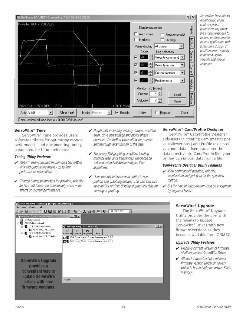
ServoWire Tune allowsmodification of thecontrol systemparameters to providethe proper response tomotion profiles specificto your application witha real-time display ofposition error, velocitycommand, actualvelocity and torqueresponse.
ORMEC -19- SERVOWIRE PRO SOFTWARE
ServoWire® TuneServoWire® Tune provides users
software utilities for optimizing motionperformance, and documenting tuningparameters for future reference.
Tuning Utility Features✔ Perform user-specified motion on a ServoWire
axis and graphically display up to fourperformance parameters.
✔ Change tuning parameters for position, velocityand current loops and immediately observe theeffects on system performance.
ServoWire® UpgradeThe ServoWire® Upgrade
Utility provides the user withthe means to updateServoWire® Drives with newfirmware versions as theybecome available from ORMEC.
Upgrade Utility Features✔ Displays current version of firmware
of all connected ServoWire Drives.✔ Allows for download of a different
firmware version (older or newer),which is burned into the drives’ Flashmemory.
✔ Graph data including velocity, torque, positionerror, drive bus voltage and motor phasecurrents. Zoom/Pan views allow for preciseand thorough examination of the data.
✔ Frequency Plot graphing simplifies locatingmachine resonance frequencies, which can bereduced using Soft Motion’s digital filteralgorithms.
✔ User-friendly interface with ability to savemotion and graphing setups. The user can alsosave and/or retrieve displayed graphical data forviewing or printing.
ServoWire® Cam/Profile DesignerServoWire® Cam/Profile Designer
aids users in creating Cam (master pos.vs. follower pos.) and Profile (axis pos.vs. time) data. Users can enter thedata directly into Cam/Profile Designer,or they can import data from a file.
Cam/Profile Designer Utility Features✔ View commanded position, velocity,
acceleration and jerk data for the specifiedmotion.
✔ Set the type of interpolation used on a segmentby segment basis.
ServoWire Upgradeprovides a
convenient way toupdate ServoWiredrives with new
firmware versions.
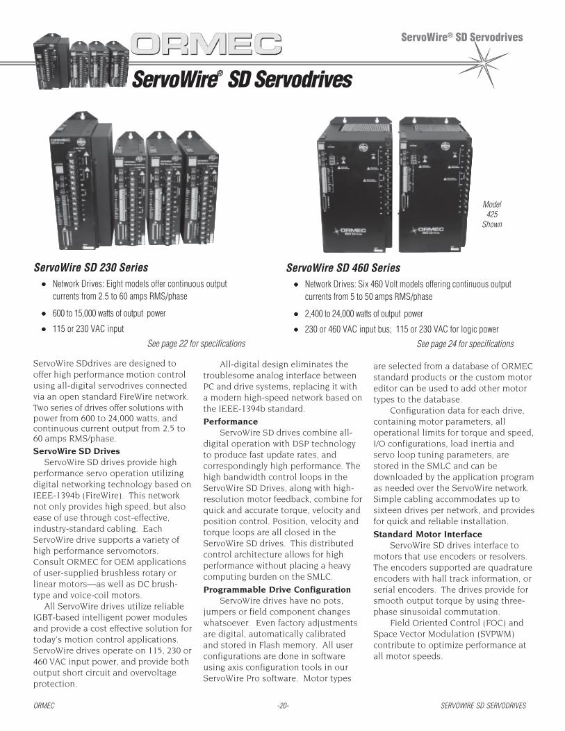
ServoWire® SD Servodrives
ServoWire® SD Servodrives
ServoWire SD 230 Series••••• Network Drives: Eight models offer continuous output
currents from 2.5 to 60 amps RMS/phase
••••• 600 to 15,000 watts of output power
••••• 115 or 230 VAC input
See page 22 for specifications
ServoWire SD 460 Series••••• Network Drives: Six 460 Volt models offering continuous output
currents from 5 to 50 amps RMS/phase
••••• 2,400 to 24,000 watts of output power
••••• 230 or 460 VAC input bus; 115 or 230 VAC for logic power
See page 24 for specifications
ServoWire SDdrives are designed tooffer high performance motion controlusing all-digital servodrives connectedvia an open standard FireWire network.Two series of drives offer solutions withpower from 600 to 24,000 watts, andcontinuous current output from 2.5 to60 amps RMS/phase.
ServoWire SD DrivesServoWire SD drives provide high
performance servo operation utilizingdigital networking technology based onIEEE-1394b (FireWire). This networknot only provides high speed, but alsoease of use through cost-effective,industry-standard cabling. EachServoWire drive supports a variety ofhigh performance servomotors.Consult ORMEC for OEM applicationsof user-supplied brushless rotary orlinear motors—as well as DC brush-type and voice-coil motors.
All ServoWire drives utilize reliableIGBT-based intelligent power modulesand provide a cost effective solution fortoday’s motion control applications.ServoWire drives operate on 115, 230 or460 VAC input power, and provide bothoutput short circuit and overvoltageprotection.
All-digital design eliminates thetroublesome analog interface betweenPC and drive systems, replacing it witha modern high-speed network based onthe IEEE-1394b standard.
PerformanceServoWire SD drives combine all-
digital operation with DSP technologyto produce fast update rates, andcorrespondingly high performance. Thehigh bandwidth control loops in theServoWire SD Drives, along with high-resolution motor feedback, combine forquick and accurate torque, velocity andposition control. Position, velocity andtorque loops are all closed in theServoWire SD drives. This distributedcontrol architecture allows for highperformance without placing a heavycomputing burden on the SMLC.
Programmable Drive ConfigurationServoWire drives have no pots,
jumpers or field component changeswhatsoever. Even factory adjustmentsare digital, automatically calibratedand stored in Flash memory. All userconfigurations are done in softwareusing axis configuration tools in ourServoWire Pro software. Motor types
ORMEC -20- SERVOWIRE SD SERVODRIVES
Model425
Shown
are selected from a database of ORMECstandard products or the custom motoreditor can be used to add other motortypes to the database.
Configuration data for each drive,containing motor parameters, alloperational limits for torque and speed,I/O configurations, load inertia andservo loop tuning parameters, arestored in the SMLC and can bedownloaded by the application programas needed over the ServoWire network.Simple cabling accommodates up tosixteen drives per network, and providesfor quick and reliable installation.
Standard Motor InterfaceServoWire SD drives interface to
motors that use encoders or resolvers.The encoders supported are quadratureencoders with hall track information, orserial encoders. The drives provide forsmooth output torque by using three-phase sinusoidal commutation.
Field Oriented Control (FOC) andSpace Vector Modulation (SVPWM)contribute to optimize performance atall motor speeds.
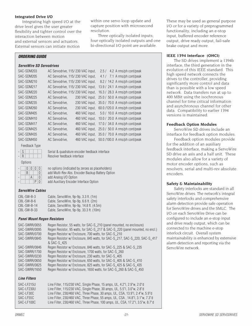
ORDERING GUIDE
ServoWire SD ServodrivesSAC-SDM203 AC Servodrive, 115/ 230 VAC input, 2.5 / 4.2 A rms/ph cont/peakSAC-SDM205 AC Servodrive, 115/ 230 VAC input, 4.1 / 7.1 A rms/ph cont/peakSAC-SDM210 AC Servodrive, 115/ 230 VAC input, 8.2 / 14.2 A rms/ph cont/peakSAC-SDM217 AC Servodrive, 115/ 230 VAC input, 13.9 / 24.1 A rms/ph cont/peakSAC-SDM220 AC Servodrive, 115/ 230 VAC input, 16.3 / 28.3 A rms/ph cont/peakSAC-SDM225 AC Servodrive, 230 VAC input, 25.0 / 50.0 A rms/ph cont/peakSAC-SDM235 AC Servodrive, 230 VAC input, 35.0 / 70.0 A rms/ph cont/peakSAC-SDM260 AC Servodrive, 230 VAC input, 60.0 /120.0 A rms/ph cont/peakSAC-SDM405 AC Servodrive, 460 VAC input, 5.0 / 10.0 A rms/ph cont/peakSAC-SDM410 AC Servodrive, 460 VAC input, 10.0 / 20.0 A rms/ph cont/peakSAC-SDM417 AC Servodrive, 460 VAC input, 17.0 / 34.0 A rms/ph cont/peakSAC-SDM425 AC Servodrive, 460 VAC input, 25.0 / 50.0 A rms/ph cont/peakSAC-SDM435 AC Servodrive, 460 VAC input, 35.0 / 70.0 A rms/ph cont/peakSAC-SDM450 AC Servodrive, 460 VAC input, 50.0 /100.0 A rms/ph cont/peak
Feedback Type
- S Serial & quadrature encoder feedback interface- R Resolver feedback interface
Options
- 0 0 0 0 no options (indicated by zeroes as placeholders)- B 0 add Multi-Rev Abs. Encoder Backup Battery Option- A 0 add Analog I/O Option- P 0 add Auxiliary Encoder Interface Option
ServoWire Cables
CBL-SW-B-3 Cable, ServoWire, 9p-9p, 3.3 ft. (1m)CBL-SW-B-6 Cable, ServoWire, 9p-9p, 6.6 ft. (2m)CBL-SW-B-14 Cable, ServoWire, 9p-9p, 14.8 ft. (4.5m)CBL-SW-B-33 Cable, ServoWire, 9p-9p, 33.3 ft. (10m)
Panel Mount Regen Resistors
SAC-SWRR/0055 Regen Resistor, 55 watts, for SAC-S_210 (panel mounted, no enclosure)SAC-SWRR/0095 Regen Resistor, 95 watts, for SAC-S_217 & SAC-S_220 (panel mounted, no encl.)SAC-SWRR/0700 Regen Resistor w/ Enclosure, 700 watts, for SAC-S_210SAC-SWRR/0845 Regen Resistor w/ Enclosure, 845 watts, for SAC-S_217, SAC-S_220, SAC-S_417
& SAC-S_425SAC-SWRR/0846 Regen Resistor w/ Enclosure, 846 watts, for SAC-S_225 & SAC-S_235SAC-SWRR/1700 Regen Resistor w/ Enclosure, 1700 watts, for SAC-S_260SAC-SWRR/0230 Regen Resistor w/ Enclosure, 230 watts, for SAC-S_405SAC-SWRR/0650 Regen Resistor w/ Enclosure, 650 watts, for SAC-S_405 & SAC-S_410SAC-SWRR/0825 Regen Resistor w/ Enclosure, 825 watts, for SAC-S_425 & SAC-S_435SAC-SWRR/1650 Regen Resistor w/ Enclosure, 1650 watts, for SAC-S_260 & SAC-S_450
Line Filters
SAC-LF215U Line Filter, 115/230 VAC, Single Phase, 15 amps, UL, 4.2"l, 2.9"w, 2.0"dSAC-LF230U Line Filter, 115/230 VAC, Single Phase, 30 amps, UL, 5.5"l, 3.0"w, 2.8"dSAC-LF30C Line Filter, 230/460 VAC, Three Phase, 30 amps, UL, CSA, 13.9"l, 2.4"w, 5.9"dSAC-LF55C Line Filter, 230/460 VAC, Three Phase, 55 amps, UL, CSA , 14.8"l, 3.1"w, 7.3"dSAC-LF100C Line Filter, 230/460 VAC, Three Phase, 100 amps, UL, CSA, 17.2"l, 3.5"w, 8.7"d
ORMEC -21- SERVOWIRE SD SERVODRIVES
These may be used as general purposeI/O or for a variety of preprogrammedfunctionality, including an e-stopinput, buffered encoder referenceoutput, drive ready output, fail-safebrake output and more.
IEEE 1394 Interface (OHCI)The SD drives implement a 1394b
interface, the third generation in theevolution of this IEEE standard. Thishigh speed network connects thedrives to the controller, providingsignificantly more control and datathan is possible with a low speednetwork. Data transfers run at up to400 MBit using the isochronouschannel for time critical informationand asynchronous channel for otherdata. Compatibility to earlier 1394versions is maintained.
Feedback Option ModulesServoWire SD drives include an
interface for feedback option modules.Feedback option modules provide
for the addition of an auxiliaryfeedback interface, making a ServoWireSD drive an axis and a half unit. Thesemodules also allow for a variety ofmotor encoder options, such asresolvers, serial and multi-rev absoluteencoders.
Safety & MaintainabilitySafety interlocks are standard in all
ServoWire drives. The network’s integralsafety interlocks and comprehensivealarm detection provide safe operationfor ServoWire drives and the SMLC. TheI/O on each ServoWire Drive can beconfigured to include an e-stop inputand drive ready output, which can beconnected to the machine e-stopinterlock circuit. Overall systemmaintainability is enhanced by extensivealarm detection and reporting via theServoWire network.
Integrated Drive I/OIntegrating high speed I/O at the
drive level gives the user greaterflexibility and tighter control over theinteraction between motionand external sensors and actuators.External sensors can initiate motion
within one servo loop update andcapture position with microsecondresolution.
Three optically isolated inputs,four optically isolated outputs and onebi-directional I/O point are available.

ServoWire® SD 230 Series Drives
ServoWire® 230 Series Drives
ORMEC -22- SERVOWIRE 230 SERIES DRIVES
Up to 16ServoWire SDdrives can benetworkeddirectly to theSMLC usingstandard cabling.
Up to 16 ServoWire SD drives can beinterfaced to the SMLC utilizing theServoWire protocol for motion controlnetworking. Eight models offercontinuous output currents from 2.5 to60 amps RMS/phase at 115 or 230 VAC.The all-digital design eliminates allmanual drive setup including pots andjumpers.
Drive Features
✔ Small Footprint: higher power density reducesspace requirements
✔ Sinusoidal commutation: improves low speedtorque ripple and system efficiency
✔ Trapezoidal commutation & DC operation:provide user flexibility
✔ Field Oriented Control (FOC) and Space VectorModulation (SVPWM): optimal performance at allmotor speeds.
✔ Integral shunt regulators: for regenerative loaddissipation (All models except SAC-SDM203 &SDM205).
✔ UL/CE approvals: UL Listed and CE Mark (lowvoltage directive & EMC)
✔ Status Indicator: Two digit display for network ID& drive status
✔ ServoWire Network Interface: Three connectorsprovide an all-digital control link to ServoWireNetwork, which is galvanically isolated from thedrive and powered by the SMLC.
✔ Drive Power Inputs: Input power accepts 115 or230 VAC nominal featuring separate logic and bus
power supplies with overvoltage protection.
✔ Analog I/O: One 14-bit input; one 14-bit output
✔ Flexible Drive I/O: ServoWire drives provide twohigh speed sensor inputs, four optically isolatedoutputs (one output can be used as a user-configurable fail-safe brake control output andanother as a drive ready output), three opticallyisolated inputs (one input can be used as an e-stop input and/or as hardware overtravel limitswitch inputs) and one bi-directional I/O point.Diagnostic LEDs aid debugging and terminalblocks make connecting easy.
✔ External Regen & Bus Connections: Allows bus
power to be shared between drives (Models SAC-SDM225, SDM235 & SDM260 only) and/or theaddition of an external resistor for dissipatingregenerative energy from the system (Allmodels except SAC-SDM203 & SDM205).
✔ Feedback Types: All models available withEncoder or Resolver feedback interface.
✔ Brushless Motor Feedback : Versatile encoderfeedback interface accommodates quadratureencoders, and differential or single-ended halltracks.
✔ Serial Encoders: Supports serial encodersincluding Yaskawa Sigma II and Tamagawa.
Integrated Drive I/O✔ High Speed Sensors: Each drive provides interfaces for two high-speed sensors. The ASEN
and BSEN inputs, along with the internal encoder reference signal, can capture real-timeaxis position for either or both axes within one microsecond of assertion. They can initiateaxis motion on the next position loop update (between 0.375 and 1.0 msec delay—depending on loop rate).
✔ E-Stop and Overtravel Limit Inputs: Each drive provides optically isolated inputs, which canbe configured as hardware overtravel limits or an E-Stop.
✔ Brake Output: A user-configurable output is provided for control of fail-safe brakes. Brakeoptions are available for H-Series servomotors.
✔ Drive Ready: A user-configurable output is provided to indicate when the drive isoperating normally, without faults. This output is intended for use in the system e-stopinterlock circuit.
✔ Zero Reference Output: A buffered motor zero reference (index mark) output signal isavailable.
✔ Diagnostic LEDs: Each I/O point has a visual indicator of its state.✔ Terminal Blocks: Easy wiring to 3.81mm pitch terminal blocks.

Mounting Information for SAC-SDM-225, 235 & 260
Mounting Information for SAC-SDM-203, 205, 210, 217 & 220
L3
L2
L1
Bus+
Bus-
RG
W
V
U
t
r
J2
1394
SER
VO
WIR
E
SH
OUT2OUT3O5/Z
OUT1
J4 M
OTO
R FE
EDB
AC
K
I4/O4O4TRN
V+S
IN1IN2IN3
V-SV+S
V-S
ASENBSEN
SH
TB4
TB5
J3
ID/STATUS
J1
BUS POWER
1.50 [38.1]
2.6 [66]3.9 [99]
6.0 [153]
Heat sink
Fan intake areaKeep clear of obstruction.
forSD-217/220
.1 [2.5]
8.7 [220]
Minimum dismountclearance 1.30 [33]
Mounting hole .210 [5.3] dia.Use 10-32 or M5 machinescrew. (Qty 3)
.54 [14]
9.0 [229]
3.75 [95.2]
8.3 [210]
10.5 [267] cable connector clearance
8.7 [220]
Fan is integral partof heatsink for
SD_-220
Optional Pacer2.5 [63.5]
cable connector clearance
.40 [10.2]
TB5I4/O4
O5/Z
O4TRN
OUT1
OUT3OUT2
SH
IN1
IN3IN2
V+SV-S
V-SV+SBSENASEN
TB4
SER
VO
WIR
E13
94 J2J3
J1
ID/STATUS
J4 M
OTO
R FE
EDB
AC
K
SH
U
V
W
RG
Bus-
Bus+
L1
L2
L3
SH
TB1TB2
rt
BUSPOWER
screw. (Qty 4)Use 10-32 or M5 machineMounting hole .210 [5.3] dia.
.1 [2.5]
11.68 [297]
12.0 [305]
.4 [10.2]
Minimum dismountclearance
4.00 [102]6.72 [171]
1.36 [35.4]
11.1 [282] minimum cable clearance
8.45 [215]
12.0 [305]
Minimum Fan Clearance(4"h x 4"w x 4"d)
Optional Pacer2.5 [63.5]
minimum cableclearance
ORMEC -23- SERVOWIRE 230 SERIES DRIVES
Specifications
Main Circuit Power❒ 115 or 230 VAC +15%, -20%, 50/60 Hz,
single phase or three phase
Control Circuit Power❒ 115 or 230 VAC, +15%, -20%, 50/60 Hz, 56
watts RMS, single phase
Position Command/Control Loop Update Rates❒ Digital position command from the host PC
via the ServoWire® network.❒ Position loop updated on command at up to
2.66 kHz (application dependent).❒ Velocity loop update rate: up to 5 kHz❒ Torque loop update rate: 10 kHz
ServoWire® Drive Output❒ 600 to 15,000 watts of output power (see
Servomotor Selection Charts for powerrequirements on matching drives)
❒ IGBT pulse width-modulated with sinusoidalor trapezoidal commutation
❒ Large heat sinks (fan cooled on SAC-SDM220 – SDM260)
❒ Internal shunt regulator for regenerative loaddissipation on all except SDM203 &SDM205
❒ Peak currents up to 200% of RMScontinuous capability
❒ DC Bus voltage of 325 VDC at nominal inputof 230 VAC and 163 VDC at 115 VAC
ServoWire® Drive I/O❒ Sensor inputs are software configurable for
either NPN or PNP output transistor typesand level or edge triggered response
❒ Sensor inputs provide one microsecondresponse time to capture machine positionand initiate motion within one servo loopupdate
❒ Optically isolated interface for generalpurpose and motor reference outputsupdated every servo loop update with amaximum sink current of 33ma per output
❒ External I/O power supply connections willaccept 5-24 VDC (240mA maximum) topower input and output circuits
Motor Encoder Feedback Interface❒ Three differential input channels for encoder
position feedback with 5.3 volt encoderpower supplied
❒ Quadrature feedback 4x decoding with datarates to 8 MHz (after decode)
❒ Open-wire detection on quadrature channelsA and B
❒ Support for serial encoders includingYaskawa Sigma II and Tamagawa
❒ Three differential input channels for motorcommutation feedback
❒ Input connections for thermal contact frommotor windings
❒ Industry standard D-sub connector (25-pinfemale) interface
Motor Resolver Feedback Interface❒ Configurable conversion resolution of 12,14,
or 16 bits position counts per revolution❒ Configurable reference signal excitation
frequency and transformation ratio❒ Input connections for thermal contact from
motor windings❒ Industry standard D-sub connector (25-pin
male) interface
Environmental❒ Ambient operating is 0 to 50C❒ Ambient storage is -20 to 70C❒ Humidity operating/storage is 90% RH or
less (non-condensing).
Drive Weights❒ SAC-SDM203, 3.7 lbs (1.7 kg)❒ SAC-SDM205, 3.7 lbs (1.7 kg)❒ SAC-SDM210, 4.1 lbs (1.9 kg)❒ SAC-SDM217, 5.8 lbs (2.6 kg)❒ SAC-SDM220, 6.6 lbs (3.0 kg)❒ SAC-SDM225, 17.7 lbs (8.0 kg)❒ SAC-SDM235, 17.7 lbs (8.0 kg)❒ SAC-SDM260, 17.7 lbs (8.0 kg)
ServoWire® SD 460 Series Drives
ServoWire® 460 Series Drives
ORMEC -24- SERVOWIRE 460 SERIES DRIVES
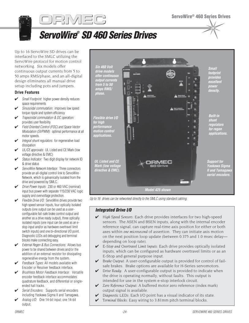
Up to 16 ServoWire SD drives can beinterfaced to the SMLC utilizing theServoWire protocol for motion controlnetworking. Six models offercontinuous output currents from 5 to50 amps RMS/phase, and an all-digitaldesign eliminates all manual drivesetup including pots and jumpers.
Drive Features
✔ Small Footprint: higher power density reducesspace requirements
✔ Sinusoidal commutation: improves low speedtorque ripple and system efficiency
✔ Trapezoidal commutation & DC operation:provides user flexibility
✔ Field Oriented Control (FOC) and Space VectorModulation (SVPWM): optimal performance at allmotor speeds.
✔ Integral shunt regulators: for regenerative loaddissipation
✔ UL/CE approvals: UL Listed and CE Mark (lowvoltage directive & EMC)
✔ Status Indicator: Two digit display for network ID& drive status
✔ ServoWire Network Interface: Three connectorsprovide an all-digital control link to ServoWireNetwork, which is galvanically isolated from thedrive and powered by SMLC.
✔ Drive Power Inputs: 230 or 460 VAC (nominal)input bus power with separate 115/230 VAC logicsupply and overvoltage protection.
✔ Flexible Drive I/O: ServoWire drives provide twohigh speed sensor inputs, four optically isolatedoutputs (one output can be used as a user-configurable fail-safe brake control output andanother as a drive ready output), three opticallyisolated inputs (one input can be used as an e-stop input and/or as hardware overtravel limitswitch inputs) and one bi-directional I/O point.Diagnostic LEDs aid debugging and terminalblocks make connecting easy.
✔ External Regen & Bus Connections: Allows buspower to be shared between drives and/or theaddition of an external resistor for dissipatingregenerative energy from the system.
✔ Feedback Types: All models available withEncoder or Resolver feedback interface.
✔ Brushless Motor Feedback Interface: Versatileencoder feedback interface accommodatesquadrature feedback, and differential or single-ended hall tracks.
✔ Serial Encoders: Supports serial encodersincluding Yaskawa Sigma II and Tamagawa.
✔ Analog I/O: One 14-bit input; one 14-bitoutput.
Integrated Drive I/O✔ High Speed Sensors: Each drive provides interfaces for two high-speed
sensors. The ASEN and BSEN inputs, along with the internal encoderreference signal, can capture real-time axis position for either or bothaxes within one microsecond of assertion. They can initiate axis motionon the next position loop update (between 0.375 and 1.0 msec delay—depending on loop rate).
✔ E-Stop and Overtravel Limit Inputs: Each drive provides optically isolatedinputs, which can be configured as hardware overtravel limits or as anE-Stop and general purpose input.
✔ Brake Output: A user-configurable output is provided for control of fail-safe brakes. Brake options are available for H-Series servomotors.
✔ Drive Ready: A user-configurable output is provided to indicate whenthe drive is operating normally, without faults. This output isintended for use in the system e-stop interlock circuit.
✔ Zero Reference Output: A buffered motor zero reference (index mark)output signal is available.
✔ Diagnostic LEDs: Each I/O point has a visual indicator of its state.✔ Terminal Blocks: Easy wiring to 3.81mm pitch terminal blocks.
Six 460 Voltdrive modelsoffer continuousoutput currentsfrom 5 to 50amps RMS/phase.
Up to 16 drives can be networked directly to the SMLC using standard cabling.
Support forYaskawa SigmaII and Tamagawaserial encoders.
Built-inshuntregulatorsfor regenapplications.
Smallfootprintprovidesexcellentpowerdensity.
Flexible drive I/Ofor highperformancemotion controlapplications.
UL Listed and CEMark (low voltagedirective & EMC).
Model 425 shown
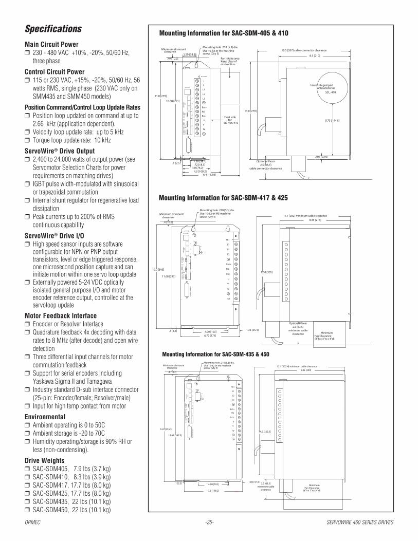
Mounting Information for SAC-SDM-417 & 425
Mounting Information for SAC-SDM-405 & 410
J4 M
OTO
R FE
EDB
AC
K
V+SV-S
SHO4TRN
O5/ZOUT3OUT2OUT1
I4/O4IN3IN2IN1
V-SV+S
SH
BSENASEN
TB5
TB4
SER
VO
WIR
E
ID/STATUS
1394
J3J2
J1
RG
Bus-
U
V
W
Bus+
r
t
L1
L2
L3
BUS POWER
10.5 [267] cable connector clearance
8.3 [210]
.1 [2.5] .72 [18.3]1.50 [38.1] Optional Pacer
2.5 [63.5]cable connector clearance
SD-405/410for
11.0 [279]
10.68 [271]
Heat sink
screw. (Qty 3)Use 10-32 or M5 machineMounting hole .210 [5.3] dia.
Minimum dismount
1.50 [38.1]clearance
obstruction.Keep clear of Fan intake area
6.4 [162.6]
3.0 [76.2]4.3 [109.2]
11.0 [279]
of heatsink forFan is integral part
SD_-410
5.73 [144.8]
.40 [10.16]
.40 [10.2]
TB5I4/O4
O5/Z
O4TRN
OUT1
OUT3OUT2
SH
IN1
IN3IN2
V+SV-S
V-SV+SBSENASEN
TB4
SER
VO
WIR
E13
94 J2J3
J1
ID/STATUS
J4 M
OTO
R FE
EDB
AC
K
SH
U
V
W
RG
Bus-
Bus+
L1
L2
L3
SH
TB1TB2
rt
BUSPOWER
screw. (Qty 4)Use 10-32 or M5 machineMounting hole .210 [5.3] dia.
.1 [2.5]
11.68 [297]
12.0 [305]
.4 [10.2]
Minimum dismountclearance
4.00 [102]6.72 [171]
1.36 [35.4]
11.1 [282] minimum cable clearance
8.45 [215]
12.0 [305]
Minimum Fan Clearance(4"h x 4"w x 4"d)
Optional Pacer2.5 [63.5]
minimum cableclearance
ORMEC -25- SERVOWIRE 460 SERIES DRIVES
SpecificationsMain Circuit Power❒ 230 - 480 VAC +10%, -20%, 50/60 Hz,
three phase
Control Circuit Power❒ 115 or 230 VAC, +15%, -20%, 50/60 Hz, 56
watts RMS, single phase (230 VAC only onSMM435 and SMM450 models)
Position Command/Control Loop Update Rates❒ Position loop updated on command at up to
2.66 kHz (application dependent).❒ Velocity loop update rate: up to 5 kHz❒ Torque loop update rate: 10 kHz
ServoWire® Drive Output❒ 2,400 to 24,000 watts of output power (see
Servomotor Selection Charts for powerrequirements on matching drives)
❒ IGBT pulse width-modulated with sinusoidalor trapezoidal commutation
❒ Internal shunt regulator for regenerative loaddissipation
❒ Peak currents up to 200% of RMScontinuous capability
ServoWire® Drive I/O❒ High speed sensor inputs are software
configurable for NPN or PNP outputtransistors, level or edge triggered response,one microsecond position capture and caninitiate motion within one servo loop update
❒ Externally powered 5-24 VDC opticallyisolated general purpose I/O and motorencoder reference output, controlled at theservoloop update
Motor Feedback Interface❒ Encoder or Resolver Interface❒ Quadrature feedback 4x decoding with data
rates to 8 MHz (after decode) and open wiredetection
❒ Three differential input channels for motorcommutation feedback
❒ Support for serial encoders includingYaskawa Sigma II and Tamagawa
❒ Industry standard D-sub interface connector(25-pin: Encoder/female; Resolver/male)
❒ Input for high temp contact from motor
Environmental❒ Ambient operating is 0 to 50C❒ Ambient storage is -20 to 70C❒ Humidity operating/storage is 90% RH or
less (non-condensing).
Drive Weights❒ SAC-SDM405, 7.9 lbs (3.7 kg)❒ SAC-SDM410, 8.3 lbs (3.9 kg)❒ SAC-SDM417, 17.7 lbs (8.0 kg)❒ SAC-SDM425, 17.7 lbs (8.0 kg)❒ SAC-SDM435, 22 lbs (10.1 kg)❒ SAC-SDM450, 22 lbs (10.1 kg)
Mounting Information for SAC-SDM-435 & 450
.1 [2.5]
7.8 [198.2]
4.00 [102]1.86 [47.3]
(6"h x 7"w x 4"d)
2.5 [63.5]minimum cable
clearanceFan Clearance
Minimum
13.68 [347.5]
14.0 [355.5]14.0 [355.5]
screw. (Qty 4)Use 10-32 or M5 machineMounting hole .210 [5.3] dia.
Minimum dismountclearance
.4 [10.2]
12.1 [307.4] minimum cable clearance
9.45 [240]
J4 M
OTO
R FE
EDB
AC
KTB
5
r
SER
VO
WIR
E
TB4
J2J3
1394 t
J1
TB2
ID/STATUS BUSPOWER
BSEN
OUT2OUT3O5/Z
IN2
O4TRNSHOUT1
IN3I4/O4
V-SV+S
IN1
V+SV-S
SHASEN
SH
W
V
U
L3
RG
L1
L2
TB1
BUS+
BUS-

ServoWire® Low Power Drive
ServoWire® LP Drive
ORMEC -26- SERVOWIRE LP DRIVE
Small Drive Footprint &Excellent Power DensityThe ServoWire SM LP drive provides anhighly space-efficient design and excellentpower density in a space-efficient, panel-mountable drive footprint.
Advantages
••••• Conserve panel space with a highlyefficient drive footprint
• Drive can be mounted only 1/2 inchapart to further conserve space
KEY FEATURES
❒ Low Power Drive: Offer 3.0 ampsRMS/phase continuous output currents
❒ Compact Size
❒ All-Digital Operation: No manualdrive settings. Totally configurable insoftware -- unlike other low powerdrives.
❒ FireWire Motion Networking:IEEE-1394 drive network
❒ ServoWire Pro: Software utilitiesfor drive configuration, diagnosticsand maintenance
••••• One model: offering 3.0 ampsRMS/phase continuous outputcurrents
••••• Network Drives: Up to 16ServoWire SM drives interfaceto an SMLC utilizing theServoWire protocol formotion control networking.
••••• Brushless or DC Servomotors:Standard feedback interface usesquadrature encoders and halltrack information, serialencoders and resolvers(optional) for brushlessoperation.
The ServoWire SM Low-Power Drive offers high performance motion controlusing all-digital servodrives (3.0 amps RMS/phase continuous outputcurrents) connected via an open standard FireWire network.
Key Features❒ All-digital, low power: The LP drive offers the unique
combination of low power and all-digital performance. Most lowpower drives are analog input drives which are difficult to calibrate,setup and maintain. The LP drive eliminates all manual drive settings andis totally configurable in software using ORMEC’s ServoWire Promaintenance and diagnostic tool.
❒ Compact Size: The LP drive delivers a space efficient designand power in its space-efficient, panel-mountable drivefootprint.
❒ Drive Networking Saves on Installation & Setup:Discrete wiring is a thing of the past -- anddramatically reduces installation and setup costs.
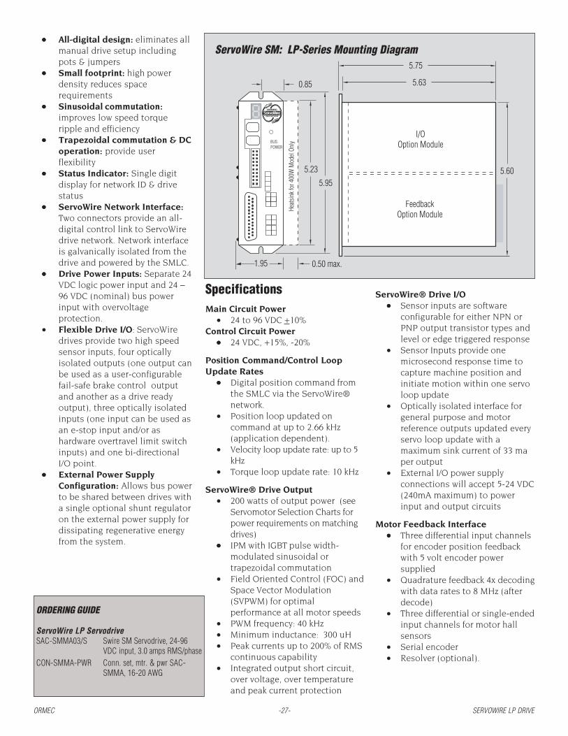
ORMEC -27- SERVOWIRE LP DRIVE
SpecificationsMain Circuit Power
• 24 to 96 VDC +10%Control Circuit Power
••••• 24 VDC, +15%, -20%
Position Command/Control LoopUpdate Rates
••••• Digital position command fromthe SMLC via the ServoWire®network.
• Position loop updated oncommand at up to 2.66 kHz(application dependent).
• Velocity loop update rate: up to 5kHz
• Torque loop update rate: 10 kHz
ServoWire® Drive Output• 200 watts of output power (see
Servomotor Selection Charts forpower requirements on matchingdrives)
••••• IPM with IGBT pulse width-modulated sinusoidal ortrapezoidal commutation
• Field Oriented Control (FOC) andSpace Vector Modulation(SVPWM) for optimalperformance at all motor speeds
• PWM frequency: 40 kHz• Minimum inductance: 300 uH• Peak currents up to 200% of RMS
continuous capability• Integrated output short circuit,
over voltage, over temperatureand peak current protection
ServoWire SM: LP-Series Mounting Diagram••••• All-digital design: eliminates all
manual drive setup includingpots & jumpers
••••• Small footprint: high powerdensity reduces spacerequirements
••••• Sinusoidal commutation:improves low speed torqueripple and efficiency
••••• Trapezoidal commutation & DCoperation: provide userflexibility
••••• Status Indicator: Single digitdisplay for network ID & drivestatus
••••• ServoWire Network Interface:Two connectors provide an all-digital control link to ServoWiredrive network. Network interfaceis galvanically isolated from thedrive and powered by the SMLC.
••••• Drive Power Inputs: Separate 24VDC logic power input and 24 –96 VDC (nominal) bus powerinput with overvoltageprotection.
• Flexible Drive I/O: ServoWiredrives provide two high speedsensor inputs, four opticallyisolated outputs (one output canbe used as a user-configurablefail-safe brake control outputand another as a drive readyoutput), three optically isolatedinputs (one input can be used asan e-stop input and/or ashardware overtravel limit switchinputs) and one bi-directionalI/O point.
••••• External Power SupplyConfiguration: Allows bus powerto be shared between drives witha single optional shunt regulatoron the external power supply fordissipating regenerative energyfrom the system.
ServoWire® Drive I/O••••• Sensor inputs are software
configurable for either NPN orPNP output transistor types andlevel or edge triggered response
• Sensor Inputs provide onemicrosecond response time tocapture machine position andinitiate motion within one servoloop update
• Optically isolated interface forgeneral purpose and motorreference outputs updated everyservo loop update with amaximum sink current of 33 maper output
• External I/O power supplyconnections will accept 5-24 VDC(240mA maximum) to powerinput and output circuits
Motor Feedback Interface••••• Three differential input channels
for encoder position feedbackwith 5 volt encoder powersupplied
• Quadrature feedback 4x decodingwith data rates to 8 MHz (afterdecode)
• Three differential or single-endedinput channels for motor hallsensors
• Serial encoder• Resolver (optional).
1.95
5.95
5.23
5.75
5.63
5.60
I/OOption Module
FeedbackOption Module
0.50 max.
Heats
ink f
or 4
00W
Mod
el On
lyBUSPOWER
0.85
ORDERING GUIDE
ServoWire LP ServodriveSAC-SMMA03/S Swire SM Servodrive, 24-96
VDC input, 3.0 amps RMS/phaseCON-SMMA-PWR Conn. set, mtr. & pwr SAC-
SMMA, 16-20 AWG

H-Series Servomotors
AC Brushless Servomotors
ORMEC -28- H-SERIES SERVOMOTORS
ORMEC’s H-series AC brushlessservomotors provide high torque-to-inertia ratios and excellent continuoustorque and peak torque performance ina compact design. These industrial-quality servomotors incorporate high-energy, rare earth, neodymium-iron-boron magnets and a highly efficientstator winding design which results inexcellent power density.
The H-series servomotors alsocompletely eliminate brush wearmaintenance problems, and featureextremely durable construction whichincludes heavy duty bearings.
Rugged MS connectors providereliable interconnections to bothmotor and optical encoder.
Features ❒ Continuous stall torques from 3 to
665 in-lb (0.32 to 75 N-m) ❒ High peak torques from 8 to 1,000
in-lb (0.96 to 113 N-m) ❒ Output power from 100 to 11,000
watts (0.13 to 15 HP) ❒ High maximum speeds from 3,000
to 5,000 RPM ❒ Incremental encoder resolutions up
to 131,072 counts per revolution ❒ Optional absolute encoders feature
multi-rev operation up to 1,048,576cts/rev.
❒ Class B or F insulation providinglong winding life under ratedoperating conditions
❒ Minimum torque ripple & coggingfor smooth low-speed performance
❒ Totally Enclosed Non-Ventilated(TENV) standard IP-67 except shaftopening, optional shaft oil seal isavailable.
❒ Optional fail-safe holding brakes
Motor/Drive CombinationsThe performance of these ser-
vomotors is a direct function of thefactory-matched servomotor/drivecombination.
ORMEC’s ServoWire® drivesprovide software controlled all-digitalperformance for consistent operationthat totally eliminates analog potenti-
ometer adjustments. High bandwidthoperation and a quality high resolutionencoder provide the response &accuracy for demanding applications.Peak torques up to three times therated torque are available for a fewseconds, allowing the motor/drive tohandle high inertial loads & heavy dutycycle requirements. Each drive’smotor parameters are configured insoftware for high performance and RMScurrent limiting.
Absolute Encoder OptionCost-effective absolute en-
coder support provides axis positionover a range of 65,536 revolutions. Incontinuous uni-directional operation,the position count continually “wraps”through the full range while main-taining absolute position within thecycle. Position is maintained throughpower cycles by a lithium battery(optional) on the ServoWire® digitaldrive.
Understanding the H-Series Servomotor Model NumbersUnderstanding the H-Series Servomotor Model NumbersUnderstanding the H-Series Servomotor Model NumbersUnderstanding the H-Series Servomotor Model NumbersUnderstanding the H-Series Servomotor Model Numbers
MAC - MAC - MAC - MAC - MAC - HE HE HE HE HE 021 021 021 021 021 AAAAA ///// AAAAA BBBBB
Subgroup Types(HE, HA or HB-Series)
B = 24 VDCFail-Safe Brake 3
Continuous stall torque(lb-in)
A = Absolute EncoderI = Incremental Encoder
A = 110 VAC 1
B = 230 VACC = 460 VAC
1 110 VAC operation is only available on MAC-HE003 and HE006 motors.2 Specify ServoWire drive with absolute encoder support when ordering this motor.3 Specify cables with the brake option when selecting a motor with a Fail-Safe brake.
ORMEC's H-series servomotors offer continuous stall torques from 3 to 665 lb-in (0.32 to 75 N-m).
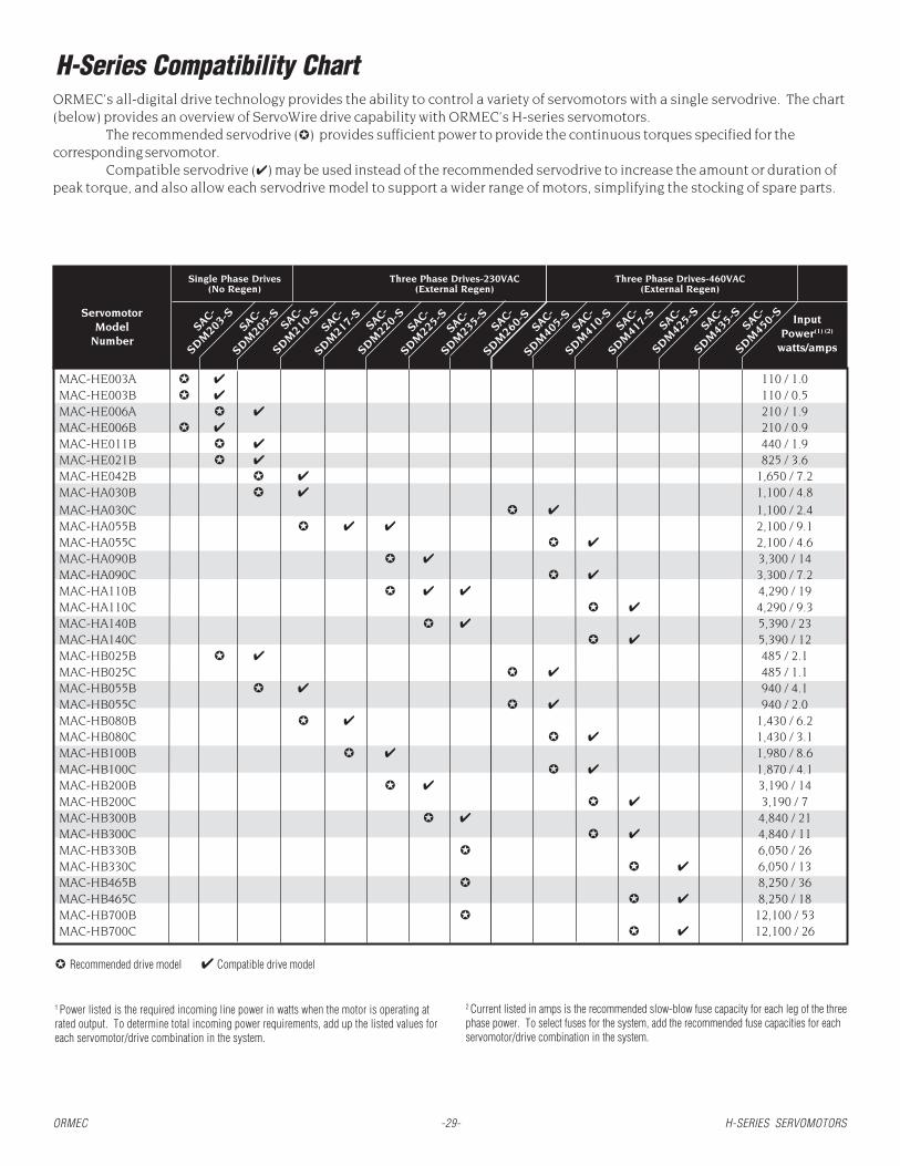
SAC-SW
203
SM
S-203
G03
ServomotorModel
Number
Single Phase Drives(No Regen)
Three Phase Drives(External Regen)
SAC-SW
205
SM
S-205
G05 SAC-S
W21
0
SM
S-210
G10 SAC-S
W21
7
SM
S-217
G17 SAC-S
W22
0
SM
S-220
G20 SAC-S
W22
5
SM
S-225
G25 SAC-S
W23
5
SM
S-235
G35 SAC-S
W26
0
SM
S-260
G60
SAC-
SDM20
3-SServomotor
ModelNumber
Single Phase Drives(No Regen)
Three Phase Drives-230VAC(External Regen)
✪ Recommended drive model ✔ Compatible drive model
MAC-HE003A ✪ ✔ 110 / 1.0MAC-HE003B ✪ ✔ 110 / 0.5MAC-HE006A ✪ ✔ 210 / 1.9MAC-HE006B ✪ ✔ 210 / 0.9MAC-HE011B ✪ ✔ 440 / 1.9MAC-HE021B ✪ ✔ 825 / 3.6MAC-HE042B ✪ ✔ 1,650 / 7.2MAC-HA030B ✪ ✔ 1,100 / 4.8
MAC-HA030C ✪ ✔ 1,100 / 2.4MAC-HA055B ✪ ✔ ✔ 2,100 / 9.1MAC-HA055C ✪ ✔ 2,100 / 4.6MAC-HA090B ✪ ✔ 3,300 / 14MAC-HA090C ✪ ✔ 3,300 / 7.2MAC-HA110B ✪ ✔ ✔ 4,290 / 19MAC-HA110C ✪ ✔ 4,290 / 9.3MAC-HA140B ✪ ✔ 5,390 / 23MAC-HA140C ✪ ✔ 5,390 / 12MAC-HB025B ✪ ✔ 485 / 2.1MAC-HB025C ✪ ✔ 485 / 1.1MAC-HB055B ✪ ✔ 940 / 4.1MAC-HB055C ✪ ✔ 940 / 2.0MAC-HB080B ✪ ✔ 1,430 / 6.2MAC-HB080C ✪ ✔ 1,430 / 3.1MAC-HB100B ✪ ✔ 1,980 / 8.6MAC-HB100C ✪ ✔ 1,870 / 4.1MAC-HB200B ✪ ✔ 3,190 / 14MAC-HB200C ✪ ✔ 3,190 / 7MAC-HB300B ✪ ✔ 4,840 / 21MAC-HB300C ✪ ✔ 4,840 / 11MAC-HB330B ✪ 6,050 / 26MAC-HB330C ✪ ✔ 6,050 / 13MAC-HB465B ✪ 8,250 / 36MAC-HB465C ✪ ✔ 8,250 / 18MAC-HB700B ✪ 12,100 / 53MAC-HB700C ✪ ✔ 12,100 / 26
SAC-
SDM20
5-S
SAC-
SDM21
0-S
SAC-
SDM21
7-S
SAC-
SDM22
0-S
SAC-
SDM22
5-S
SAC-
SDM23
5-S
SAC-
SDM26
0-S
SAC-
SDM40
5-S
SAC-
SDM41
0-S
SAC-
SDM41
7-S
SAC-
SDM42
5-S
SAC-
SDM43
5-S
SAC-
SDM45
0-S InputPower(1) (2)
watts/amps
110 / 1.0Three Phase Drives-460VAC
(External Regen)
H-Series Compatibility Chart
2 Current listed in amps is the recommended slow-blow fuse capacity for each leg of the threephase power. To select fuses for the system, add the recommended fuse capacities for eachservomotor/drive combination in the system.
1 Power listed is the required incoming line power in watts when the motor is operating atrated output. To determine total incoming power requirements, add up the listed values foreach servomotor/drive combination in the system.
ORMEC -29- H-SERIES SERVOMOTORS
ORMEC’s all-digital drive technology provides the ability to control a variety of servomotors with a single servodrive. The chart(below) provides an overview of ServoWire drive capability with ORMEC’s H-series servomotors.
The recommended servodrive (✪) provides sufficient power to provide the continuous torques specified for thecorresponding servomotor.
Compatible servodrive (✔) may be used instead of the recommended servodrive to increase the amount or duration ofpeak torque, and also allow each servodrive model to support a wider range of motors, simplifying the stocking of spare parts.

H-Series AC Brushless Servomotors
(1) Ratings are obtained with servomotor ambient temperature of 40C, and armature winding temperature of 100C. (2) Motor’s peak torque is limited by the peak current of the servodrive.The next larger drive may be used to increase the amount of peak torque available. Consult an ORMEC Applications Engineer for details.
Performance Specifications (1) Units HE003A HE003B HE006AMaximum Speed RPM 5,000 5,000 5,000Continuous Stall Torque lb-in 2.8 2.8 5.6
N-m 0.32 0.32 0.64Rated Speed RPM 3,000 3,000 3,000Rated Torque lb-in 2.8 2.8 5.6
N-m 0.32 0.32 0.64Rated Power HP 0.13 0.13 0.27
watts 100 100 200Peak Torque(2) lb-in 5.1 8.2 14
N-m 0.58 0.93 1.5Continuous Stall Torque/Inertia radians/sec2 64,437 64,437 32,786
Mechanical Specifications
Moment of Inertia lb-in-sec2 x 10-3 0.043 0.043 0.171kg-m2 x 10-4 0.049 0.049 0.193
Friction Torque, Static lb-in 0.048 0.048 0.11N-m 0.0054 0.0054 0.012
Servomotor Weight lbs 1.5 1.5 3.1kg 0.7 0.7 1.4
Maximum Radial Shaft Load lbs 17 17 55 (centered at end of shaft) N 78 78 245Maximum Axial Shaft Load lbs 11 11 15
N 49 49 68
Electrical SpecificationsTorque Sensitivity lb-in/Amp
Rms/Ø1.4 3.5 2.3
N-m/AmpRms/Ø
0.16 0.39 0.26Servodrive Model Number SAC- SDM203-S SDM203-S SDM205-SServodrive Input Power volts AC 115 230 115Continuous Motor Current Amps
Rms/Ø2.2 0.89 2.7
Peak Motor Current AmpsRms/Ø
7.1 2.8 8.4
Motor Thermal SpecificationsAmbient Temperature degrees C 40 40 40Insulation Class B B B
Encoder Specifications
Incremental Encoder Resolution counts/revolution 8,192 8,192 8,192
Absolute Encoder Resolution counts/revolution 65,536 65,536 65,536
Inertia specifications for Brake Models on page 37.
MAC-HE003A
0
1
2
3
4
5
0 1000 2000 3000 4000 5000
N-mlb-in lb-in
RPM
Torque vs. Speed CharacteristicsTT
TORQ
UE
A: Intermittent Duty Zone B: Continuous Duty Zone
MAC-HE006A
0
2
8
10
0 1000 2000 3000 4000 5000
N-mlb-in
12
14
0.5
0.4
0.3
0.2
0.1
0.6
0
1.25
1.00
0.75
0.50
0.25
1.50
0.0
Rated torque
Rated torque
Rated speed
0
1
2
3
4
5
6
7
8
MAC-HE003B
0 1000 2000 3000 4000 5000
N-m
Rated speed
Rated torque
0.0
0.625
0.50
0.375
0.75
0.875
ORMEC -30- H-SERIES SERVOMOTORS

ORMEC -31- H-SERIES SERVOMOTORS
H-Series AC Brushless Servomotors
(1) Ratings are obtained with servomotor ambient temperature of 40C, and armature winding temperature of 100C. (2) Motor’s peak torque is limited by the peak current of theServoWireTM drive. The next larger drive may be used to increase the amount of peak torque available. Consult an Ormec Applications Engineer for details.
Performance Specifications (1) Units HE006B HE011B HE021BMaximum Speed RPM 5,000 5,000 4,700Continuous Stall Torque lb-in 5.6 11 21
N-m 0.64 1.3 2.4Rated Speed RPM 3,000 3,000 3,000Rated Torque lb-in 5.6 11 21
N-m 0.64 1.3 2.4Rated Power HP 0.27 0.54 1.0
watts 200 400 750Peak Torque(2) lb-in 11 28 34
N-m 1.3 3.2 3.9Continuous Stall Torque/Inertia radians/sec2 32,786 37,551 11,088
Mechanical SpecificationsMoment of Inertia lb-in-sec2 x 10-3 0.171 0.293 1.86
kg-m2 x 10-4 0.193 0.331 2.10Friction Torque, Static lb-in 0.11 0.20 0.32
N-m 0.012 0.022 0.036Servomotor Weight lbs 3.1 4.6 9.3
kg 1.4 2.1 4.2Maximum Radial Shaft Load lbs 55 55 88 (centered at end of shaft) N 245 245 392Maximum Axial Shaft Load lbs 15 15 33
N 68 68 147
Electrical SpecificationsTorque Sensitivity lb-in/Amp
Rms/Ø3.1 4.7 5.7
N-m/AmpRms/Ø
0.35 0.54 0.64Servodrive Model Number SAC- SDM203-S SDM205-S SDM205-SServodrive Input Power volts AC 230 230 230Continuous Motor Current Amps
Rms/Ø2.0 2.6 4.1
Peak Motor Current AmpsRms/Ø
6.0 8.0 14
Motor Thermal SpecificationsAmbient Temperature degrees C 40 40 40Insulation Class B B B
Encoder SpecificationsIncremental Encoder Resolution counts/revolution 8,192 8,192 8,192Absolute Encoder Resolution counts/revolution 65,536 65,536 65,536
Inertia specifications for Brake Models on page 37.
MAC-HE006B
RPM
Torque vs. Speed CharacteristicsTT
TORQ
UE
A: Intermittent Duty Zone B: Continuous Duty Zone
0
2
4
6
8
10
0 1000 2000 3000 4000 5000
N-mlb-in
1.0
0.8
0.6
0.4
0.2
0.0
1.2
Rated torque
Rated speed
MAC-HE011B
0
5
10
15
20
25
0 1000 2000 3000 4000 5000
N-mlb-in
0
2.5
2.0
1.5
1.0
0.5
3.0
Rated torque
Rated speed
MAC-HE021B
0
5
10
15
30
0 1000 2000 3000 4000 50000.0
3.5
2.5
2.0
1.5
N-m
1.0
0.5
lb-in
3.0
35 4.0
Rated torque
Rated speed
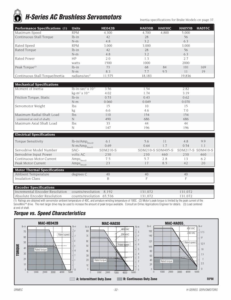
ORMEC -32- H-SERIES SERVOMOTORS
H-Series AC Brushless Servomotors
(1) Ratings are obtained with servomotor ambient temperature of 40C, and armature winding temperature of 100C. (2) Motor’s peak torque is limited by the peak current of theServoWireTM drive. The next larger drive may be used to increase the amount of peak torque available. Consult an Ormec Applications Engineer for details. (3) Load centeredat end of shaft.
Performance Specifications (1) Units HE042B HA030B HA030C HA055B HA055CMaximum Speed RPM 4,300 4,700 4,800 5,000Continuous Stall Torque lb-in 42 28 56
N-m 4.8 3.2 6.3Rated Speed RPM 3,000 3,000 3,000Rated Torque lb-in 42 28 56
N-m 4.8 3.2 6.3Rated Power HP 2.0 1.3 2.7
watts 1500 1000 2000Peak Torque(2) lb-in 73 68 84 101 169
N-m 8.3 7.7 9.5 11 19Continuous Stall Torque/Inertia radians/sec2 11,575 18,183 19,836
Mechanical SpecificationsMoment of Inertia lb-in-sec2 x 10-3 3.56 1.54 2.82
kg-m2 x 10-4 4.02 1.74 3.19Friction Torque, Static lb-in 0.53 0.43 0.62
N-m 0.060 0.049 0.070Servomotor Weight lbs 15 10 15
kg 6.6 4.6 7.0Maximum Radial Shaft Load lbs 110 154 154 (centered at end of shaft) N 490 686 686Maximum Axial Shaft Load lbs 33 44 44
N 147 196 196
Electrical Specifications
Torque Sensitivity lb-in/AmpRms/Ø
6.1 5.6 11 4.8 9.9N-m/Amp
Rms/Ø0.69 0.64 1.7 0.54 1.1
Servodrive Model Number SAC- SDM210-S SDM210-S SDM405-S SDM217-S SDM410-SServodrive Input Power volts AC 230 230 460 230 460Continuous Motor Current Amps
Rms/Ø7.5 5.7 2.8 13 6.2
Peak Motor Current AmpsRms/Ø
23 17 8.5 42 20
Motor Thermal SpecificationsAmbient Temperature degrees C 40 40 40Insulation Class B F F
Encoder SpecificationsIncremental Encoder Resolution counts/revolution 8,192 131,072 131,072Absolute Encoder Resolution counts/revolution 65,536 131,072 131,072
Inertia specifications for Brake Models on page 37.
MAC-HE042B
0
10
20
30
40
50
60
0 1000 2000 3000 4000 50000
7
5
4
3
N-m
2
1
lb-in
RPM
6
Torque vs. Speed CharacteristicsTT
TORQ
UE
A: Intermittent Duty Zone B: Continuous Duty Zone
70 8Rated speed
MAC-HA030_
0 1000 2000 3 5000
N-m
0
5
432
1
6
9
lb-in
ed
MAC-HA055_
0
20
40
60
0 1000 2000 3000 4000
N-mlb-in
80
100
5000
15
10
12.5
7.5
5
2.5
0
AC
C
120
140
160460 VAC
230 VAC2
4
7
17.5
010
30
40
50
60
70
80
Rated torque
Rated speed
8
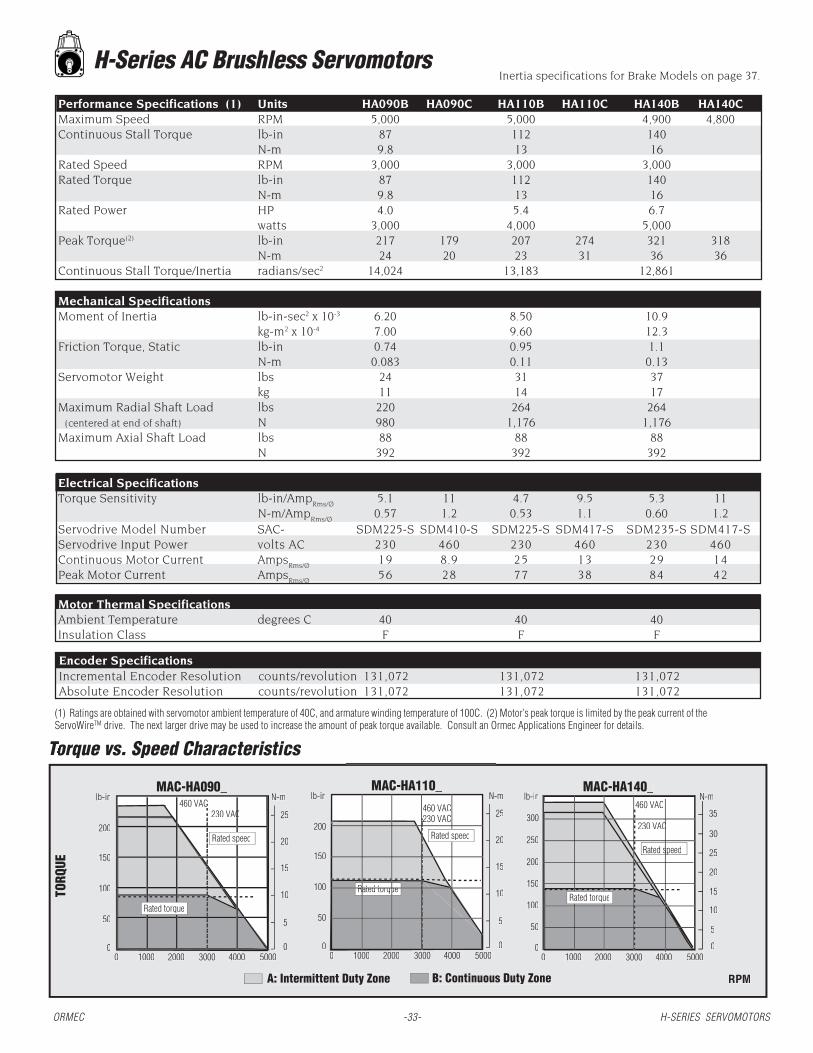
H-Series AC Brushless Servomotors
(1) Ratings are obtained with servomotor ambient temperature of 40C, and armature winding temperature of 100C. (2) Motor’s peak torque is limited by the peak current of theServoWireTM drive. The next larger drive may be used to increase the amount of peak torque available. Consult an Ormec Applications Engineer for details.
Performance Specifications (1) Units HA090B HA090C HA110B HA110C HA140B HA140CMaximum Speed RPM 5,000 5,000 4,900 4,800Continuous Stall Torque lb-in 87 112 140
N-m 9.8 13 16Rated Speed RPM 3,000 3,000 3,000Rated Torque lb-in 87 112 140
N-m 9.8 13 16Rated Power HP 4.0 5.4 6.7
watts 3,000 4,000 5,000Peak Torque(2) lb-in 217 179 207 274 321 318
N-m 24 20 23 31 36 36Continuous Stall Torque/Inertia radians/sec2 14,024 13,183 12,861
Mechanical SpecificationsMoment of Inertia lb-in-sec2 x 10-3 6.20 8.50 10.9
kg-m2 x 10-4 7.00 9.60 12.3Friction Torque, Static lb-in 0.74 0.95 1.1
N-m 0.083 0.11 0.13Servomotor Weight lbs 24 31 37
kg 11 14 17Maximum Radial Shaft Load lbs 220 264 264 (centered at end of shaft) N 980 1,176 1,176Maximum Axial Shaft Load lbs 88 88 88
N 392 392 392
Electrical SpecificationsTorque Sensitivity lb-in/Amp
Rms/Ø5.1 11 4.7 9.5 5.3 11
N-m/AmpRms/Ø
0.57 1.2 0.53 1.1 0.60 1.2Servodrive Model Number SAC- SDM225-S SDM410-S SDM225-S SDM417-S SDM235-S SDM417-SServodrive Input Power volts AC 230 460 230 460 230 460Continuous Motor Current Amps
Rms/Ø19 8.9 25 13 29 14
Peak Motor Current AmpsRms/Ø
56 28 77 38 84 42
Motor Thermal SpecificationsAmbient Temperature degrees C 40 40 40Insulation Class F F F
Incremental Encoder Resolution counts/revolution 131,072 131,072 131,072Absolute Encoder Resolution counts/revolution 131,072 131,072 131,072
Encoder Specifications
Inertia specifications for Brake Models on page 37.
RPM
Torque vs. Speed CharacteristicsTT
TORQ
UE
A: Intermittent Duty Zone B: Continuous Duty Zone
MAC-HA090_N-mlb-in
0
50
100
150
200
0
25
15
10
5
20
0 1000 2000 3000 4000 5000
MAC-HA110_N-mlb-in
0
50
100
150
200
0
25
15
10
5
20
0 1000 2000 3000 4000 5000
Rated torque
MAC-HA140_
0 1000 2000 3000 4000 5000
Rated speedp
0
50
100
150
200
250
300
N-mlb-in
0
35
25
20
15
10
5
30
460 VACC 460 VAC
230 VAC
460 VAC
Rated speed
230 VACC
Rated torque
Rated speed
Rated torque
ORMEC -33- H-SERIES SERVOMOTORS

(1) Ratings are obtained with servomotor ambient temperature of 40C, and armature winding temperature of 100C. (2) Motor’s peak torque is limited by the peak current of the ServoWireTM
drive. The next larger drive may be used to increase the amount of peak torque available. Consult an ORMEC Applications Engineer for details.
H-Series AC Brushless ServomotorsPerformance Specifications (1) Units HB025B HB025C HB055B HB055C HB080B HB080CMaximum Speed RPM 3,000 3,000 3,000Continuous Stall Torque lb-in 25 53 74
N-m 2.8 6.0 8.4Rated Speed RPM 1,500 1,500 1,500Rated Torque lb-in 25 48 74
N-m 2.8 5.4 8.4Rated Power HP 0.60 1.1 1.7
watts 450 850 1,300Peak Torque(2) lb-in 44 68 88 105 152 177
N-m 4.9 7.7 10 12 17 20Continuous Stall Torque/Inertia radians/sec2 3,902 4,308 4,059
Mechanical Specifications
Moment of Inertia lb-in-sec2 x 10-3 6.41 12.3 18.2kg-m2 x 10-4 7.24 13.9 20.5
Friction Torque, Static lb-in 0.43 0.65 0.87N-m 0.049 0.074 0.098
Servomotor Weight lbs 12 17 21kg 5.5 7.6 9.6
Maximum Radial Shaft Load lbs 110 110 154 (centered at end of shaft) N 490 490 686Maximum Axial Shaft Load lbs 22 22 77
N 98 98 343
Electrical Specifications
Torque Sensitivity lb-in/AmpRms/Ø
7.3 15 7.3 15 7.4 15N-m/Amp
Rms/Ø0.82 1.6 0.83 1.7 0.84 1.7
Servodrive Model Number SAC- SDM205-S SDM405-S SDM210-S SDM405-S SDM217-S SDM410-SServodrive Input Power volts AC 230 460 230 460 230 460Continuous Motor Current Amps
Rms/Ø3.8 1.9 7.1 3.5 11 5.4
Peak Motor Current AmpsRms/Ø
11 5.5 17 9 28 14
Motor Thermal Specifications
Ambient Temperature degrees C 40 40 40Insulation Class F F F
Encoder SpecificationsIncremental Encoder Resolution counts/revolution 131,072 131,072 131,072Absolute Encoder Resolution counts/revolution 131,072 131,072 131,072
Inertia specifications for Brake Models on page 37.
RPM
Torque vs. Speed CharacteristicsTT
TORQ
UE
A: Intermittent Duty Zone B: Continuous Duty Zone
MAC-HB025_
0
10
20
30
40
0 1000 2000 3000 4000
N-mlb-in
50
60
70
0
8
4
3
2
1
MAC-HB055_
0
20
40
60
0 1000 2000 3000 4000
N-mlb-in
80
0
10
4
6
2
MAC-HB080_
0 1000 2000 3000 4000
N-mlb-in
0
2040
60
80100
120
140
0
12.5
10.0
7.5
5.0
2.5
20.0460 VAC
160
180 460 VAC
230 VAC
4460 VAC
230 VAC5
6
7
15.0
17.5
8
Rated speed
Rated speed
12
Rated speed
Rated torque
230 VAC
ORMEC -34- H-SERIES SERVOMOTORS

H-Series AC Brushless Servomotors Inertia specifications for Brake Models on page 37.
Performance Specifications (1) Units HB100B HB100C HB200B HB200C HB300B HB300CMaximum Speed RPM 3,000 3,000 3,000Continuous Stall Torque lb-in 102 196 300
N-m 12 22 34Rated Speed RPM 1,500 1,500 1,500Rated Torque lb-in 102 165 252
N-m 12 19 28Rated Power HP 2.4 2.3 3.9 5.9
watts 1,800 1,700 2,900 4,400Peak Torque(2) lb-in 155 214 350 479 554
N-m 18 24.2 40 54 63Continuous Stall Torque/Inertia radians/sec2 3,624 4,815 5,015
Mechanical SpecificationsMoment of Inertia lb-in-sec2 x 10-3 28.1 40.7 59.8
kg-m2 x 10-4 31.7 46.0 67.5Friction Torque, Static lb-in 1.0 1.4 2.3
N-m 0.12 0.16 0.25Servomotor Weight lbs 31 40 51
kg 14 18 23Maximum Radial Shaft Load lbs 264 330 330 (centered at end of shaft) N 1,176 1,470 1,470Maximum Axial Shaft Load lbs 110 110 110
N 490 490 490
Electrical SpecificationsTorque Sensitivity lb-in/AmpRms/Ø 6.5 13 7.3 15 8.0 16
N-m/AmpRms/Ø 0.73 1.5 0.82 1.7 0.91 1.8Servodrive Model Number SAC- SDM220-S SDM410-S SDM225-S SDM417-S SDM235-S SDM417-SServodrive Input Power volts AC 230 460 230 460 230 460Continuous Motor Current AmpsRms/Ø 17 8.4 24 12 33 17Peak Motor Current AmpsRms/Ø 42 20 56 28 84 41
Motor Thermal SpecificationsAmbient Temperature degrees C 40 40 40Insulation Class F F F
Encoder SpecificationsIncremental Encoder Resolution counts/revolution 131,072 131,072 131,072Absolute Encoder Resolution counts/revolution 131,072 131,072 131,072
(1) Ratings are obtained with servomotor ambient temperature of 40C, and armature winding temperature of 100C. (2) Motor’s peak torque is limited by the peak current of the ServoWireTM drive.The next larger drive may be used to increase the amount of peak torque available. Consult an ORMEC Applications Engineer for details.
RPM
Torque vs. Speed CharacteristicsTT
TORQ
UE
A: Intermittent Duty Zone B: Continuous Duty Zone
MAC-HB100_
0 1000 2000 3000 4000
N-mlb-in
0
20
40
60
80
100
120
140
160
0.0
12.5
10
7.5
5
2.5
15
17.5
MAC-HB200_
0 1000 2000 3000 4000
N-mlb-in
Rated torque
Rated speed
0
50
100
150
200
250
300
0
35
25
20
15
10
5
30
MAC-HB300_
0 1000 2000 3000 4000
N-mlb-in
0
100
200
300
400
500
0
60
50
40
30
20
10
460 VAC
230 VAC
460 VAC
230 VAC460 VAC230 VAC
Rated speed Rated speed
Rated torque
ORMEC -35- H-SERIES SERVOMOTORS

H-Series AC Brushless Servomotors Inertia specifications for Brake Models on page 37.
Performance Specifications (1) Units HB330B HB330C HB465B HB465C HB700B HB700CMaximum Speed RPM 3,000 3,000 2,000Continuous Stall Torque lb-in 345 450 665
N-m 39 51 75Rated Speed RPM 1,500 1,500 1,500Rated Torque lb-in 310 425 620
N-m 35 48 70Rated Power HP 7.4 10 15
watts 5,500 7,500 11,000Peak Torque(2) lb-in 728 655 839 978 1,000
N-m 82 74 95 111 113Continuous Stall Torque/Inertia radians/sec2 4,380 4,055 2,670
Mechanical SpecificationsMoment of Inertia lb-in-sec2 x 10-3 78.8 111 249
kg-m2 x 10-4 89.0 125 281Friction Torque, Static lb-in 3.0 4.2 7.2
N-m 0.33 0.47 0.81Servomotor Weight lbs 66 88 127
kg 30 40 58Maximum Radial Shaft Load lbs 397 397 397 (centered at end of shaft) N 1,764 1,764 1,764Maximum Axial Shaft Load lbs 132 132 132
N 588 588 588
Electrical SpecificationsTorque Sensitivity lb-in/Amp
Rms/Ø7.8 15 8.2 18 11 23
N-m/AmpRms/Ø
0.88 1.8 0.93 2.0 1.2 2.6Servodrive Model Number SAC- SDM260-S SDM425-S SDM260-S SDM425-S SDM260-S SDM435-SServodrive Input Power volts AC 230 460 230 460 230 460Continuous Motor Current Amps
Rms/Ø42 21 55 25 59 28
Peak Motor Current AmpsRms/Ø
110 55 130 65 140 70
Motor Thermal SpecificationsAmbient Temperature degrees C 40 40 40Insulation Class F F F
Encoder SpecificationsIncremental Encoder Resolution counts/revolution 131,072 131,072 131,072Absolute Encoder Resolution counts/revolution 131,072 131,072 131,072
(1) Ratings are obtained with servomotor ambient temperature of 40C, and armature winding temperature of 100C. (2) Motor’s peak torque is limited by the peak current of the ServoWireTM drive.The next larger drive may be used to increase the amount of peak torque available. Consult an ORMEC Applications Engineer for details.
RPM
Torque vs. Speed CharacteristicsTT
TORQ
UE
A: Intermittent Duty Zone B: Continuous Duty Zone
MAC-HB330_
0 1000 2000 3000 4000
N-mlb-in
0
200
300
400
500
600
700
0
62.5
50
37.5
25
12.5
75
MAC-HB465_
0 1000 2000 3000 4000
N-mlb-in
0 0.0
62.5
50
37.5
25
12.5
75
87.5
MAC-HB700_
0 1000 2000 3000
N-mlb-in
Rated speed
Rated torque
0
200
400
600
800
1000
0
120
100
80
60
40
20200
400
600
800
1000 460 VAC
230 VAC460 VAC60 C230 VAC
230 VAC
460 VAC
Rated speed
Rated torque
Rated speed
Rated torque
ORMEC -36- H-SERIES SERVOMOTORS

Specifications for H-Series Servomotors with Fail-Safe BrakesMODEL with BRAKE
(1)Caution: The built-in fail-safe brake is designed for holding and not for decelerating the motor. In normal operation the brake should be applied only after the motor is stopped. Fail-safebrakes are useful in applications when a servomotor is used to control a vertical axis. A servomotor with a fail-safe brake prevents the moveable part from dropping due to gravitation whenthe system power is turned OFF.
Brake Continuous MomentServomotor Holding Stall Torque of Inertia Motor Motor Brake Brake
Model Torque(1) to Inertia Ratio (lb-in-sec2 / Length Weight Coil RatedNumber (lb-in / N-m) (radians/sec2) kg-m2) (in / mm) (lb / kg) Resistance Current
MAC-HE003A 4.3 40,510 0.069 x 10⁻³ 3.6 1.5 96 .250.49 0.781 x 10⁻⁴ 91 0.7
MAC-HE003B 4.3 40,510 0.069 x 10⁻³ 3.6 1.5 96 .250.49 0.781 x 10⁻⁴ 91 0.7
MAC-HE006A 8.7 20,953 0.267 x 10⁻³ 3.9 4.2 115 .210.98 0.302 x 10⁻⁴ 99 1.9
MAC-HE006B 8.7 20,953 0.267 x 10⁻³ 3.9 4.2 115 .210.98 0.302 x 10⁻⁴ 99 1.9
MAC-HE011B 17 28,249 0.389 x 10⁻³ 4.7 5.7 76 .321.9 0.440 x 10⁻⁴ 119 2.6
MAC-HE021B 32 7,976 2.63 x 10⁻³ 4.8 13 77 .313.6 2.98 x 10⁻⁴ 123 5.7
MAC-HE042B 63 9,695 4.33 x 10⁻³ 5.8 18 58 .427.1 4.90 x 10⁻⁴ 148 8.1
MAC-HA030_ 66 15,310 1.83 x 10⁻³ 7.6 13 82 .297.8 2.07 x 10⁻⁴ 193 6.0
MAC-HA055_ 66 17,994 3.11 x 10⁻³ 9.5 19 82 .297.8 3.52 x 10⁻⁴ 242 8.5
MAC-HA090_ 177 10,749 8.09 x 10⁻³ 9.3 31 58.5 .4120 9.15 x 10⁻⁴ 237 14
MAC-HA110_ 177 10,784 10.4 x 10⁻³ 10.8 38 58.5 .4120 11.7 x 10⁻⁴ 274 17
MAC-HA140_ 177 10,958 12.8 x 10⁻³ 12.4 44 58.5 .4120 14.4 x 10⁻⁴ 314 20
MAC-HB025_ 39 3,028 8.26 x 10⁻³ 6.9 17 58.5 .414.4 9.33 x 10⁻⁴ 176 7.5
MAC-HB055_ 112 3,745 14.2 x 10⁻³ 7.8 21 58.5 .4113 16.0 x 10⁻⁴ 199 9.6
MAC-HB080_ 112 3,685 20.1 x 10⁻³ 8.8 26 58.5 .4113 22.7 x 10⁻⁴ 223 12
MAC-HB100_ 380 2,842 35.9 x 10⁻³ 8.5 42 31.1 .7743 40.6 x 10⁻⁴ 217 19
MAC-HB200_ 380 4,045 48.4 x 10⁻³ 9.6 52 31.1 .7743 54.8 x 10⁻⁴ 243 24
MAC-HB300_ 380 4,439 67.6 x 10⁻³ 10.9 63 31.1 .7743 76.4 x 10⁻⁴ 277 29
MAC-HB330_ 646 3,988 86.6 x 10⁻³ 12.2 77 24.5 .9873 97.8 x 10⁻⁴ 311 35
MAC-HB465_ 646 3,790 119 x 10-3 15.2 100 24.5 .9873 134 x 10-4 385 46
MAC-HB700_ 744 2,502 266 x 10-3 15.1 145 18 1.3384 300 x 10-4 383 67
ORMEC -37- H-SERIES SERVOMOTORS

0.0016 A
0.0008 A
0.98[25]
0.55[14]
A
OPTICALENCODERCONNECTOR
MOTORCONNECTOR
2.36[60]
1.9[48]
2.36[60]
1.97[50]
1.970[50]REF
0.315
8 + 0.000
0.12[3]
0.21 [5.3](4) HOLES THRU
L
2.76[70]
0.0016 A
0.07[1.8]
0.12[3]
LMLE
+0.000
[0.04]
[0.04]
[0.02]
0.12[3]
-0.009
+ 0.0000-0.0003
0.24[6]
-0.025
-0.001+0.000
1.18 [30]
0.120 [3]
0.28 [7][4] HOLES THRU
3.54[90]
3.15[80]
3.15 [80]
2.756[70]REF
0.551+.0000-.00043
14 +0.000-0.011
0.0016 A
0.0008 A
A
OPTICALENCODERCONNECTOR MOTOR
CONNECTOR
LELM
+.0000-.030
L
0.0016 A
2.756[70]
0.12[3]
2.3[58]
[0.04]
[0.04]
[0.02]
0.20[5]
0.20[5]
0.63[16]
0.31[8]
+.0000-.0012
HE006A, HE006B, & HE011B Outline Drawings
HE003A & HE003B Outline Drawings
SHAFT & PILOT DETAILINCHES [mm]
SHAFT & PILOT DETAILINCHES [mm]
DimensionsDimensionsDimensionsDimensionsDimensions L L L L L LELELELELE LMLMLMLMLM
MAC-HE006A 2.6 [67] 2.1 [53] 1.6 [40]
MAC-HE006B 2.6 [67] 2.1 [53] 1.6 [40]
MAC-HE011B 3.4 [87] 2.9 [73] 2.4 [60]
For length of models with brake option selected, see page 37. Call for design details.For length of models with brake option selected, see page 37. Call for design details.For length of models with brake option selected, see page 37. Call for design details.For length of models with brake option selected, see page 37. Call for design details.For length of models with brake option selected, see page 37. Call for design details. All dimensions in inches [millimeters]
DimensionsDimensionsDimensionsDimensionsDimensions L L L L L LELELELELE LMLMLMLMLM
MAC-HE003A 2.4 [62] 1.9 [48] 1.3 [32]
MAC-HE003B 2.4 [62] 1.9 [48] 1.3 [32]
Note: Minimum cable clearance from motor centerline for encoder cableis 3.2 inches (81 mm); for motor cable is 4.2 inches (107 mm). Cablelengths to connector approximately 11 inches [280 mm].
Note: Minimum cable clearance from motor centerline for encoder cableis 2.8 inches 71 mm); for motor cable is 3.8 inches (97 mm). Cablelengths to connector approximately 11 inches [280 mm].
ORMEC -38- H-SERIES SERVOMOTORS
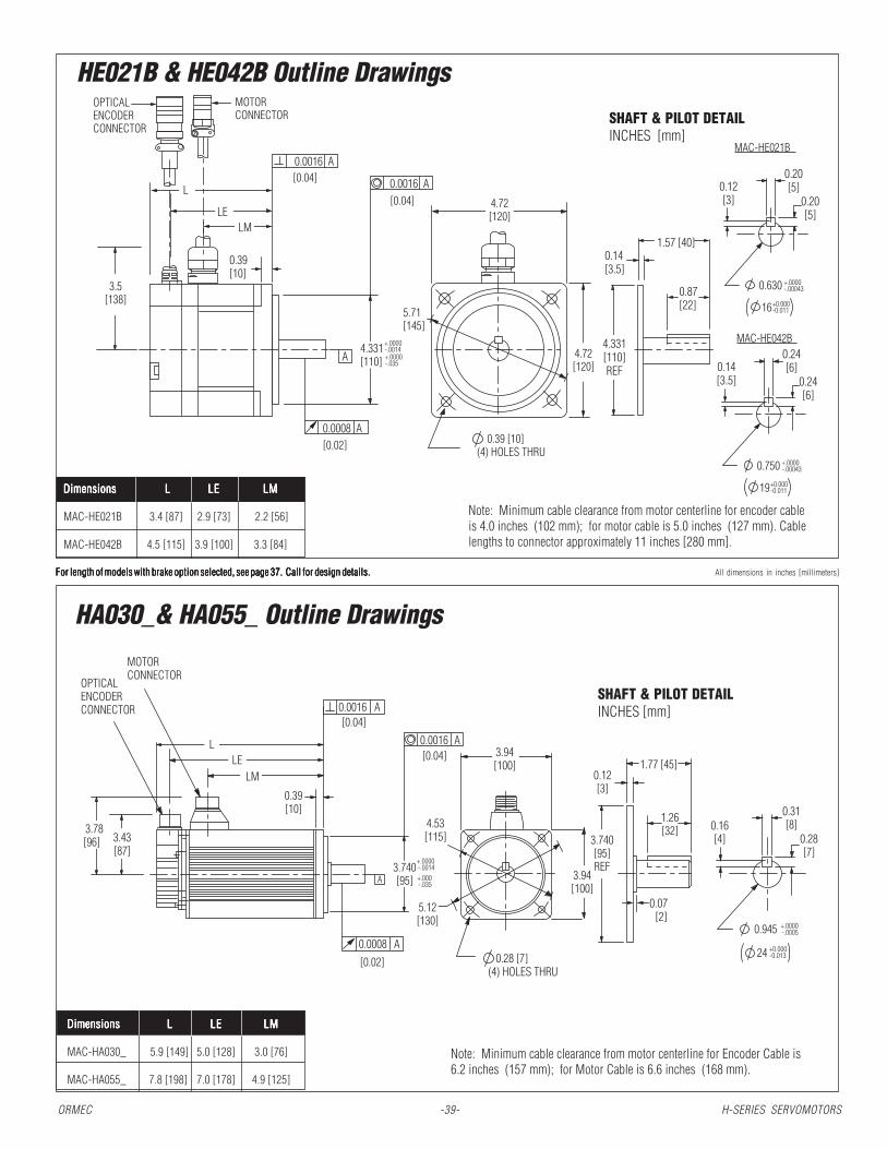
HA030_& HA055_ Outline Drawings
HE021B & HE042B Outline Drawings
SHAFT & PILOT DETAILINCHES [mm]
For length of models with brake option selected, see page 37. Call for design details.For length of models with brake option selected, see page 37. Call for design details.For length of models with brake option selected, see page 37. Call for design details.For length of models with brake option selected, see page 37. Call for design details.For length of models with brake option selected, see page 37. Call for design details. All dimensions in inches [millimeters]
DimensionsDimensionsDimensionsDimensionsDimensions L L L L L LELELELELE LMLMLMLMLM
MAC-HA030_ 5.9 [149] 5.0 [128] 3.0 [76]
MAC-HA055_ 7.8 [198] 7.0 [178] 4.9 [125]
Note: Minimum cable clearance from motor centerline for encoder cableis 4.0 inches (102 mm); for motor cable is 5.0 inches (127 mm). Cablelengths to connector approximately 11 inches [280 mm].
DimensionsDimensionsDimensionsDimensionsDimensions L L L L L LELELELELE LMLMLMLMLM
MAC-HE021B 3.4 [87] 2.9 [73] 2.2 [56]
MAC-HE042B 4.5 [115] 3.9 [100] 3.3 [84]
Note: Minimum cable clearance from motor centerline for Encoder Cable is6.2 inches (157 mm); for Motor Cable is 6.6 inches (168 mm).
SHAFT & PILOT DETAILINCHES [mm]
0.14[3.5]
+.0000-.00043
+0.000-0.011
0.39 [10](4) HOLES THRU
4.72[120]
+.0000-.035
4.72[120]
0.630
16
4.331[110]REF
1.57 [40]
0.87[22]
5.71[145]
0.0016 A
0.0008 A
A
LELM
L 0.0016 A
4.331[110]
3.5[138]
OPTICALENCODERCONNECTOR
MOTORCONNECTOR
[0.04]
[0.04]
[0.02]
0.12[3]
0.20[5]
0.20[5]
0.39[10]
+.0000-.0014
+.0000-.00043
+0.000-0.011
0.750
19
0.14[3.5]
0.24[6]
0.24[6]
MAC-HE021B
MAC-HE042B
1.77 [45]0.12[3]
3.94[100]
1.26[32]
3.94[100]
L
0.0008 A
0.39[10]
0.0016 A
0.0016 A
A
OPTICALENCODERCONNECTOR
MOTORCONNECTOR
4.53[115]
3.740[95] +.000
-.035
0.28 [7](4) HOLES THRU
0.945 +.0000-.0005
24 +0.000-0.013
+.0000-.0014
LMLE
0.16[4]3.740
[95]REF
3.78[96] 3.43
[87]
5.12[130]
[0.02]
[0.04]
[0.04]
0.31[8]
0.28[7]
0.07[2]
ORMEC -39- H-SERIES SERVOMOTORS

HB025_, HB055_ & HB080_ Outline Drawings
For length of models with brake option selected, see page 37. Call for design details.For length of models with brake option selected, see page 37. Call for design details.For length of models with brake option selected, see page 37. Call for design details.For length of models with brake option selected, see page 37. Call for design details.For length of models with brake option selected, see page 37. Call for design details. All dimensions in inches [millimeters]
Note: Minimum cable clearance from motor centerline for encoder cableis 6.3 inches (160 mm); for motor cable is 7.0 inches (178 mm).
DimensionsDimensionsDimensionsDimensionsDimensions L L L L L LELELELELE LMLMLMLMLM
MAC-HB025_ 5.4 [138] 4.6 [117] 2.5 [64]
MAC-HB055_ 6.3 [161] 5.5 [140] 3.4 [88]
MAC-HB080_ 7.3 [185] 6.5 [164] 4.4 [112]
SHAFT & PILOT DETAILINCHES [mm]
HA090_, HA110_ & HA140_ Outline Drawings
DimensionsDimensionsDimensionsDimensionsDimensions L L L L L LELELELELE LMLMLMLMLM
MAC-HA090_ 7.8 [199] 7.0 [177] 4.8 [122]
MAC-HA110_ 9.3 [236] 8.5 [215] 6.3 [159]
MAC-HA140_ 10.9 [277] 10.0 [255] 7.8 [199]
SHAFT & PILOT DETAILINCHES [mm]
Note: Minimum cable clearance from motor centerline for encoder cable is6.2 inches (157 mm); for motor cable is 7.5 inches (191 mm).
+.0000-.0014
0.35 [9](4) HOLES THRU
5.71[145]
6.50[165]
5.12[130]
2.48[63]0.24
[6]
1.97[50]
1.102
28
+.0000-.0005
+0.000-0.013
5.12[130]
4.331[110]
0.47[12]
+.000-.035
L
0.0008 A
0.0016 A
0.0016 A
A
OPTICALENCODERCONNECTOR
MOTORCONNECTOR
LMLE
4.331[110]REF
4.49[114] 3.43
[87]
[0.02]
[0.04]
[0.04]
0.31[8]
0.28[7]
0.16[4]
0.078[2] 0.59
[15]
0.0008
0.0016
OPTICALENCODERCONNECTOR
MOTORCONNECTOR
L
0.748
19 +0.000-0.013
2.28[58]0.24
[6]
0.98[25]
4.331[110]REF
0.35 [9](4) HOLES THRU
5.12[130]
5.12[130]
5.71[145]
0.47[12]
+.0000-.0005
0.866
22 +0.000-0.013
+.0000-.0005
A4.331[110] +.000
-.035
+.0000-.0014
MAC-HB025_ & MAC-HB055_
MAC-HB080_
LMLE
4.29[109] 3.46
[88]
6.50[165]
A[0.02]
[0.04]
[0.04]
A
0.0016 A0.12
[3]
0.20[5]
0.20[5]
0.14[3.5]
0.24[6]
0.24[6]
0.47[12]
0.59[15]
ORMEC -40- H-SERIES SERVOMOTORS

Note: Minimum cable clearance from motor centerline for encoder cableis 6.3 inches (160 mm); for motor cable is 9.5 inches (241 mm)
For length of models with brake option selected, see page 37. Call for design details.For length of models with brake option selected, see page 37. Call for design details.For length of models with brake option selected, see page 37. Call for design details.For length of models with brake option selected, see page 37. Call for design details.For length of models with brake option selected, see page 37. Call for design details. All dimensions in inches [millimeters]
HB700_ Outline Drawing
SHAFT & PILOT DETAILINCHES [mm]
HB100_, HB200_, HB300_, HB330_ & HB465_ Outline DrawingsSHAFT & PILOT DETAIL INCHES [mm]
DimensionsDimensionsDimensionsDimensionsDimensions L L L L L LELELELELE LMLMLMLMLM KKKKK
MAC-HB100_ 6.5 [166] 5.7 [145] 3.5 [89] 5.5 [140]MAC-HB200_ 7.5 [192] 6.7 [171] 4.5 [115] 5.5 [140]MAC-HB300_ 8.9 [226] 8.1 [205] 5.9 [149] 5.5 [140]MAC-HB330_ 10.2 [260] 9.4 [239] 6.8 [174] 5.9 [150]MAC-HB465_ 13.2 [334] 12.3 [313] 9.8 [248] 5.9 [150]
Note: Minimum cable clearance from motor centerline for encoder cableis 6.3 inches (160 mm); for motor cable is 9.5 inches (241 mm)
0.0016 A
1.654 +.0000-.0006
42 +0.000-0.016
7.874[200]REF
3.54[90]
8.66[220]
9.25[235]
0.531 [13.5](4) HOLES THRU
8.66[220]
0.16[4]
4.57 [116]
+.0000
+.0000-.0018
OPTICALENCODERCONNECTOR
MOTORCONNECTOR
13.3[338]
12.5[317] 9.9
[251]
0.71[18]
0.0016 A
0.0008 A
A
7.874[200]
6.61[168] 3.46
[88]
10.63[270]
[0.02]
[0.04]
[0.04]
0.20[5]
0.47[12]
0.31[8]
0.07[2]
0.08[22.5]
-.046
0.0016 A
1.379+.0004-.0000
35 +0.01-0.000
4.500[114.3]
REF
2.36[60]
7.09[180]
7.87[200]
0.531 [13.5](4) HOLES THRU
7.09[180]
1.654 +.0000-.0006
42 +0.000-0.006
4.500[114.3]
REF
3.54[90]
0.13[3.2]
MAC-HB100_, MAC-HB200_ & MAC-HB300_
MAC-HB330_ & MAC-HB465_
0.13[3.2]
4.45 [113]
3.11 [79]
+.0000-.025
+.0000-.001
OPTICALENCODERCONNECTOR
MOTORCONNECTOR
L
LM
0.71[18]
0.0016 A
0.0008 A
A
4.500[114.3]
LE
9.06[230]
K 3.46[88]
[0.02]
[0.04]
[0.04] 0.20[5] 0.32
[8]
0.39[10]
0.20[5]
0.47[12]
0.32[8]
ORMEC -41- H-SERIES SERVOMOTORS

MOTOR / FEEDBACK / OPTION -- MATING CONNECTOR CHARTMOTOR TYPE FIG MOTOR/POWER MATING FIG FEEDBACK MATING
115,230 & 460 VAC Motors (incremental or absolute feedback)All of MAC-HE series motors Y SRUC06JMSCN236 FIN075-B2 Z SRUC17GMRCN087 FIN17CA22
MAC-HA030B, HA055B, HB025B, DB055B, HB080B X MS-3102A18-10P MS-3106F18-10S U MS-3102A20-29P MS-3106F20-29SMAC-HA090B, HA110B, HA140B, HB100B, HB200B, HB300B X MS-3102A22-22P MS-3106F22-22S U MS-3101A20-29P MS-3106F20-29SMAC-HB330B, HB465B & HB700B X MS-3102A32-17P MS-3106F32-17S U MS-3101A20-29P MS-3106F20-29S115 & 230 VAC Motors with Fail-safe BrakeAll of MAC-HE series motors Y SRUC06JMSCN236 FIN075-B2 Z SRUC17GMRCN087 FIN17CA22MAC-HA030B, HA055B, HB025B, HB055B, HB080B W MS-3102A20-15P MS-3106F20-15S U MS-3101A20-29P MS-3106F20-29SMAC-HA090B, HA110B, HA140B, HB100B, HB200B, HB300B W MS-3102A24-10P MS-3106F24-10S U MS-3101A20-29P MS-3106F20-29SMAC-HB330B, HB465B & HB700B X MS-3102A32-17P1 MS-3106F32-17S1 U MS-3101A20-29P MS-3106F20-29S
B MS-3102A10SL-3P1 MS-3106F10SL-3S1
460 VAC Motors with Fail-safe BrakeMAC-HA030C, HA055C, HB025C, HB055C, HB080C W MS-3102A20-15P MS-3106F20-15S U MS-3101A20-29P MS-3106F20-29SMAC-HA090C, HA110C, HA140C, HB100C, HB200C, HB300C W MS-3102A24-10P MS-3106F24-10S U MS-3101A20-29P MS-3106F20-29SMAC-HB330C, HB465C & HB700C X MS-3102A32-17P1 MS-3106F32-17S1 U MS-3101A20-29P MS-3106F20-29SBrake connector for all 460 VAC H-Series motors B MS-3102A10SL-3P1 MS-3106F10SL-3S1
MOTOR / POWER RECEPTACLES
Fig. Y Fig. XFig. W
Fig. U
Servomotor ConnectorsENCODER FEEDBACK RECEPTACLES (Figure U & Z)
A 1 Phase U REDB 2 Phase V WHTC 3 Phase W BLUD 6 Ground GRNE 5 Brake Term REDF 4 Brake Term BLK
S 1 BAT-T 2 BAT+C 3 DATA+D 4 DATA-H 8 +5VDCG 9 0VJ Shell Case Ground
Connector Type Manufactured by
MS.... AmphenolFIN.... YaskawaSRU.... Interconnectron
1 Brake option requires separate motor and brake cables. 2 Requires Crimp tool B150 and positioner.
Fig. B
H-Series Encoder and Motion Cables (115 VAC and 230 VAC)Standard Flex Option3 IP-67 Sealing Brake Option Brake w/IP-67 SealingCBL-HEMSW/X CBL-HEMSWF/X N/A N/A N/A Encoder cable for HE-Series motors, 1-150 ft.CBL-HEMSW1/X CBL-HEMSWF1/X N/A CBL-HEMSWB1/X N/A Motor Cable for all MAC-HE motors , 1-150 ft.CBL-HMSW/X CBL-HMSWF/X CBL-HMSWV/X N/A N/A Encoder cable for HA & HB-Series motors, 1-150 ft.CBL-HMSW1/X CBL-HMSWF1/X CBL-HMSWV1/X CBL-HMSWB1/X CBL-HMSWVB1/X Motor cable for MAC-HA030, HA055, HB025-HB080 motors, 1-150 ft.CBL-HMSW2/X CBL-HMSWF2/X CBL-HMSWV2/X CBL-HMSWB2/X CBL-HMSWVB2/X Motor cable for MAC-HA090, HA110 & HB200 motors, 1-150 ft.CBL-HMSW3/X CBL-HMSWF3/X CBL-HMSWV3/X CBL-HMSWB3/X CBL-HMSWVB3/X Motor cable for MAC-HA140 & HB300 motors, 1-150 ft.CBL-HMSW4/X CBL-HMSWF4/X CBL-HMSWV4/X CBL-HMSWB4/X CBL-HMSWVB4/X Motor cable for MAC-HB100 motors, 1-150 ft.CBL-HMSW5/X CBL-HMSWF5/X CBL-HMSWV5/X Note: CBL-HMSWB/X is in additionNote: CBL-HMSWB/X is in additionNote: CBL-HMSWB/X is in additionNote: CBL-HMSWB/X is in additionNote: CBL-HMSWB/X is in addition Motor cable for MAC-HB330 motors, 1-150 ft.CBL-HMSW6/X CBL-HMSWF6/X CBL-HMSWV6/X to motor cable.to motor cable.to motor cable.to motor cable.to motor cable. Motor cable for MAC-HB465 & HB700 motors, 1-150 ft.
CBL-HMSWB/X CBL-HMSWVB/X Brake cable for MAC-HB330, HB465 & HB700 motors, 1-150 ft.
H-Series Encoder and Motion Cables (460 VAC)Standard Flex Option3 IP-67 Sealing Brake Option Brake w/IP-67 SealingCBL-HMSW/X CBL-HMSWF/X CBL-HMSWV/X N/A N/A Encoder cable for HA & HB-Series motors, 1-150 ft.CBL-HMSW1/X CBL-HMSWF1/X CBL-HMSWV1/X Note: CBL-HMSWB/X is in additionNote: CBL-HMSWB/X is in additionNote: CBL-HMSWB/X is in additionNote: CBL-HMSWB/X is in additionNote: CBL-HMSWB/X is in addition Motor cable for MAC-HA030, HA055, HB025-HB080 motors, 1-150 ft.CBL-HMSW2/X CBL-HMSWF2/X CBL-HMSWV2/X to motor cable.to motor cable.to motor cable.to motor cable.to motor cable. Motor cable for MAC-HA090, HA110 & HB200 motors, 1-150 ft.CBL-HMSW3/X CBL-HMSWF3/X CBL-HMSWV3/X Motor cable for MAC-HA140 & HB300 motors, 1-150 ft.CBL-HMSW4/X CBL-HMSWF4/X CBL-HMSWV4/X Motor cable for MAC-HB100 motors, 1-150 ft.CBL-HMSW5/X CBL-HMSWF5/X CBL-HMSWV5/X Motor cable for MAC-HB330 motors, 1-150 ft.CBL-HMSW6/X CBL-HMSWF6/X CBL-HMSWV6/X Motor cable for MAC-HB465 & HB700 motors, 1-150 ft.
CBL-HMSWB/X CBL-HMSWVB/X Brake cable for all 460 VAC H-Series motors, 1-150 ft.3 Consult factory for flex cables beyond 100 feet.
Note: For all cables above, specify length of the cable by adding the numerical length in the “X” placeholder in the Model Number.
BRAKE CONNECTOR (Figure B)
A Brake TermB Brake TermC --
BGE
F A
CD
2
3
4
56
7
8
11
9
1
10 12
16 13
15 14
17
D A
BC
C A
B
B
D
E
FG
H
J
K
A
L C
M
N
T P
S R
2
7
5 1
3
4
6
Fig. Z
ORMEC -42- H-SERIES SERVOMOTORS

Lineshaft Pacer Encoders
EDR-25 Series Encoders
ORMEC -43- LINESHAFT PACER ENCODERS
The ability to interface a positionencoder to a ServoWire Drive canprovide vital position information tothe motion control system.
This approach is simple, yet effec-tive, because information for the“encoder axis” is available to be used inthe same way that information is usedfrom any “servo axis”.
Uses of Remote Encoders1) Pacer Encoders measure real-time
shaft position data of a machineaxis to be sent to other servo axesin the system when electronicgearing and/or cam profiling areused in an application.
2) Programmable limit switches oneach ServoWire drive can beconfigured to turn on or off basedon pacer encoder position.
3) Position and velocity information isaccessible from the applicationprogram for every encoder used withan SMLC system.
4) Remote Feedback Encoders can beused to provide position feedbackdirectly from the load undercontrol, usually used in conjunctionwith velocity feedback from theservomotor shaft to provide anadditional level of precision for thecontrol system.
ServoWire Drive InterfaceThe encoder interface is a partial
servo axis interface, consisting only ofdifferentially received quadrature A andB channels and a reference Z-channel.Selecting the “encoder input” axiscontrol mode disables servodrive alarmdetection but still provides open wiredetection to insure encoder positioninformation integrity.
Optical Position EncodersORMEC's Model EDR-25 optical,
incremental position encoders areideal for a wide variety of ruggedindustrial applications where reliabilityis a prime concern.
LED light sources rated for 100Khours MTBF, 40 pound axial/40 pound
radial shaft loading capability, 200 KHzfrequency response allow these encod-ers to be effective in harsh, industrialapplications.
The EDR-25 provides a 1/4 cyclewide gated zero reference output.Models with cycle interpolation havemaximum resolutions up to 200,000counts per shaft revolution.
Electrical Specifications
Excitation voltages: 5 VDC @ 100 mAmaximum.
Output format: Two outputs (A andB) in phase quadrature with a zeroreference (Z) output
Output Specifications: Output stageis an MC3487 (or performance equiva-lent) differential line driver with 20 masink and -20 ma source current.
Mechanical Specifications
Maximum Shaft loading: 80 lb. max,40 lb. rated, axially and radially
Shaft radial runout: 0.001" T.I.R.
Maximum Starting torque at 25C: 3.0 oz-in typical
Shaft angular acceleration:105 radians/sec2 (maximum)
Moment of inertia: 5.2 x 10⁻⁴ oz-in-sec2
Bearing type: Precision ABEC ballbearing
Minimum Bearing Life: 1.5 x 10⁹
revolutions at rated shaft loading.
Shaft: 303 stainless steel
Maximum shaft speed: 8000 RPMor 200 KHz count channel outputfrequency, whichever occurs first(before cycle interpolation).
Weight: 11 oz. typical (25S) 14 oz. typical (25C)
Environmental Specifications
Operating temperature range:0 to +70C
Storage temperature range:-25 to +85C
Maximum Shock:75G’s for 11 milliseconds duration
Vibration:58 Hz to 500 Hz at 20G’s
Maximum Humidity:98% R.H. (non-condensing)
ORDERING GUIDELineshaft Pacer Encoders
EDR-25S/A1000 Position Encoder: 1000 linecount, servo mount provides 4,000 counts per revEDR-25S/A1250 Position Encoder: 1250 linecount, servo mount provides 5,000 counts per revEDR-25S/A2500 Position Encoder: 2500 linecount, servo mount provides 10,000 counts per revEDR-25S/A5000 Position Encoder: 5000 linecount, servo mount provides 20,000 counts per revEDR-25S/B5000 Position Encoder: 10,000 linecount, servo mount provides 40,000 counts per revEDR-25S/E2500 Position Encoder: 12,500 linecount, servo mount provides 50,000 counts per revEDR-25S/D5000 Position Encoder: 20,000 linecount, servo mount provides 80,000 counts per revEDR-25S/E5000 Position Encoder: 25,000 linecount, servo mount provides 100,000 counts per revEDR-25S/F5000 Position Encoder: 25,000 linecount, servo mount provides 100,000 counts per rev,
high freq.EDR-25S/G5000 Position Encoder: 50,000 linecount, servo mount provides 200,000 counts per rev,
high freq.
Note: To specify encoder with flange mount and integral coupling, replace “25S” in model numbersabove with “25C”.
CBL-QE25SW/X Encoder Cable, EDR-25 to ServoWire Drive, 5-150 ftCBL-QE25SWV/X Encoder Cable, EDR-25 to ServoWire Drive, IP-67, water-resistant, 5-150 ftCON-E25 Encoder Connector, for EDR-25 Encoders
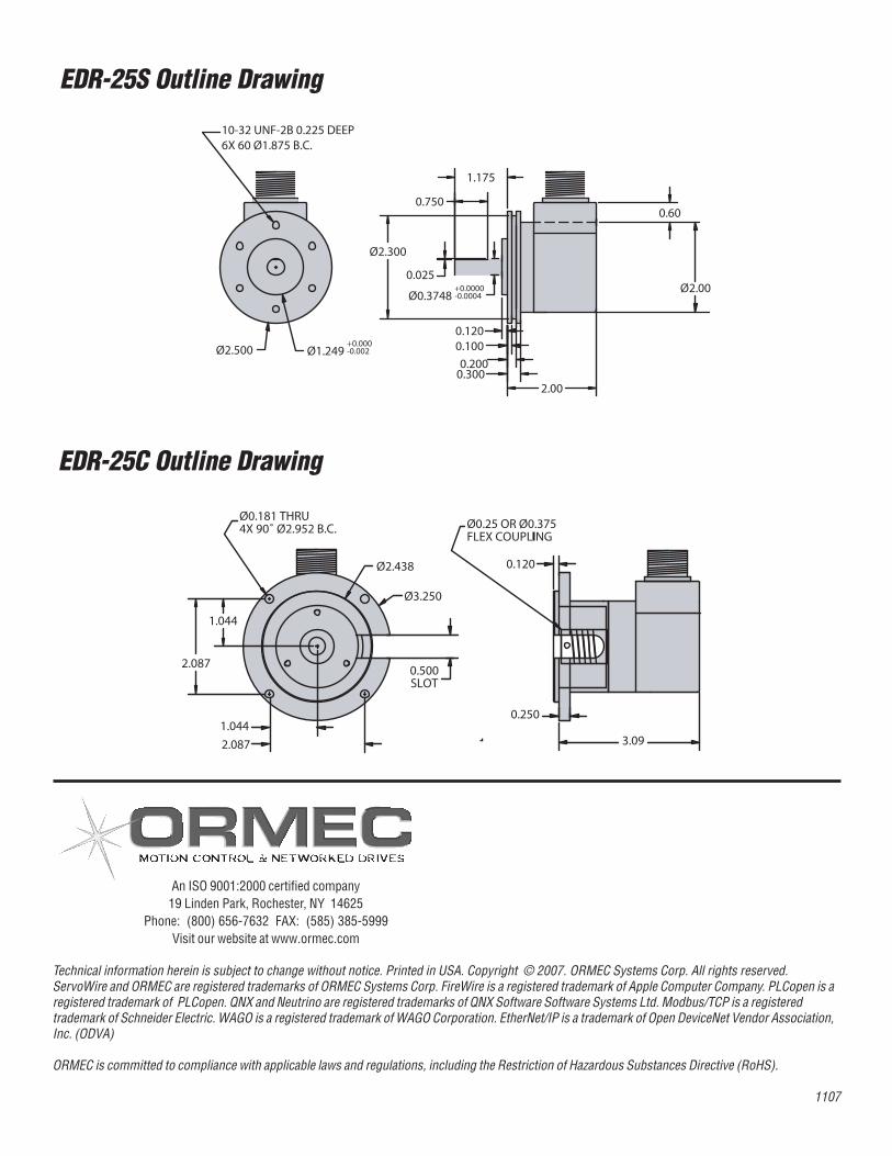
Technical information herechnical information herein is subject to change without notice. Printed in USA.Copyright © 2003. ORMEC Systems Corp. All rights reserved. ServoWire and ORMEC are registered trademarks of ORMEC Systems Corp. FireWireis a registered trademark of Apple Computer Company. Modbus TCP is a trademark of Schneider Electrein is subject to change without notice. Printedin USA.Copyright © 2003. ORMEC Systems Corp. All rights reserved. ServoWire and ORMEC are registered trademarks of ORMEC Systems Corp. FireWireis a registered trademark of Apple Computer Company. Modbus TCP is a trademark of Schneider Electric.
Technical information herein is subject to change without notice. Printed in USA. Copyright © 2007. ORMEC Systems Corp. All rights reserved.ServoWire and ORMEC are registered trademarks of ORMEC Systems Corp. FireWire is a registered trademark of Apple Computer Company. PLCopen is aregistered trademark of PLCopen. QNX and Neutrino are registered trademarks of QNX Software Software Systems Ltd. Modbus/TCP is a registeredtrademark of Schneider Electric. WAGO is a registered trademark of WAGO Corporation. EtherNet/IP is a trademark of Open DeviceNet Vendor Association,Inc. (ODVA)
ORMEC is committed to compliance with applicable laws and regulations, including the Restriction of Hazardous Substances Directive (RoHS).
1107
An ISO 9001:2000 certified company19 Linden Park, Rochester, NY 14625
Phone: (800) 656-7632 FAX: (585) 385-5999Visit our website at www.ormec.com
EDR-25S Outline Drawing
EDR-25C Outline Drawing
Ø0.3748+0.0000-0.0004
0.600.750
0.025
0.120
2.00
1.175
Ø2.00
Ø2.300
0.3000.200
0.100
10-32 UNF-2B 0.225 DEEP6X 60 Ø1.875 B.C.
Ø2.500 Ø1.249+0.000-0.002