
Smith Meter AccuLoad III VLR Simulator for AccuLoad...
22
Bulletin MN06116 ║ Issue/Rev 0.3 (10/13) Smith Meter ® AccuLoad ® III VLR Simulator for AccuLoad ® III Installation / Operation Manual
Transcript of Smith Meter AccuLoad III VLR Simulator for AccuLoad...

Bulletin MN06116 ║ Issue/Rev 0.3 (10/13)
Smith Meter® AccuLoad® III
VLR Simulator for AccuLoad® IIIInstallation / Operation Manual

i
Caution
The default or operating values used in this manual and in the program of the AccuLoad III are for factory
testing only and should not be construed as default or operating values for your metering system. Each metering
system is unique and each program parameter must be reviewed and programmed for that specific metering
system application.
Disclaimer
FMC Technologies Measurement Solutions, Inc. hereby disclaims any and all responsibility for damages, includ-
ing but not limited to consequential damages, arising out of or related to the inputting of incorrect or improper pro-
gram or default values entered in connection with the AccuLoad III.

Table of Contents
ii
Section I - Introduction ................................................................................................................................................1
Introduction .............................................................................................................................................................1 Product Description .................................................................................................................................................1 Receipt of Equipment ..............................................................................................................................................1
Section II - Installation ................................................................................................................................................2 System Requirements .............................................................................................................................................2 EAAI Requirements.................................................................................................................................................2 Communication Wiring ............................................................................................................................................2 Program (VLR) Installation ......................................................................................................................................2 AccuLoad I/O Functions ..........................................................................................................................................3
Section III - Operation .............................................................................................................................................. 14 Section IV - Related Publications ............................................................................................................................ 18

iii

Section I – Introduction
MN06116 Issue/Rev. 0.3 (10/13) 1
Introduction
This manual is to be used for the installation of the Smith Meter AccuLoad III Virtual Load Rack Simula-tor Kit onto a PC-based computer system. The man-ual is divided into four sections: Introduction, Instal-lation, Operation, and Related Publications.
"Installation" describes step-by-step procedures for installing the VLR program on the PC-based com-puter system.
“Operation” describes the functions and operation of the VLR program.
"Related Publications" lists the literature associated with the AccuLoad III products.
Product Description
The VLR (Virtual Load Rack Simulator) is a Win-dows-based application designed to simulate the functions of the meter, valve, additives, temperature transducer, pressure transducer, density transducer, and truck grounding and overfill systems. This simu-lator is used to demonstrate the functions of the AccuLoad III.
Receipt of Equipment
The VLR Simulator is shipped with every AccuLoad III Demo unit. It consists of the following:
ALX
VLR simulator software
a simulator board mounted on the EAAI board
a simulator PROM (U8) installed on the EAAI board
a cable from the EAAI board (TB6) to the PC for the simulator
a cable for the KDC (TB1) to the PC for the AccuMate.
When the equipment is received, the outside pack-ing case should be checked immediately for any shipping damage. If the packing case has been damaged, the local carrier should be notified at once regarding liability. Carefully remove the unit from its packing case and inspect for damaged or missing parts.
If damage has occurred during shipment or if parts are missing, a written report should be submitted to the Customer Service Department, FMC Technolo-gies Measurement Solutions, 1602 Wagner Avenue, Erie, Pennsylvania 16514.
Before installation, the unit should be stored in its original packing case and protected from adverse weather conditions and abuse.

Section II - Installation
2 MN06116 Issue/Rev. 0.3 (10/13)
System Requirements
The VLR will operate on an IBM PC-compatible (Pentium 90 MHz or better) computer operating in a Windows environment (Windows 95 or later) with at least 4M of memory, CD drive, and a mouse. The hard drive should have at least 4M of free disk space.
EAAI Requirements
The EAAI board must be set up as follows to oper-ate the VLR Simulator (see Figure 1):
232 Plug-in board installed in CN4
VLR_EAAI PROM installed in U8
Jumpers J4 and J5 removed
JP1 configuration for analog inputs and outputs (4 Ain and 2 Aout)
JP1:7-8 Open
JP1:9-10 Shorted
JP1:11-12 Shorted
Communication Wiring
The communication wiring between the PC and the AccuLoad III should be set up as follows:
ALS1/ALD1
PC (9-pin) AccuLoad III
2 TB6-1 (Tx)
3 TB6-2 (Rx)
5 TB6-3 (Gnd)
ALQ1, ALQ3, ALQ4
PC (9-pin) AccuLoad III - EAAI
2 TB6-1 (Tx)
3 TB6-2 (Rx)
5 TB6-3 (Gnd)
Jumper from EAAI AccuLoad III BSE
TB6-1 (Tx) TB14-1 (Tx)
TB6-2 (Rx) TB14-2 (Rx)
TB6-3 (Gnd) TB14-3 (Gnd)
Program (VLR) Installation
Note: Be certain to close all other programs before installation.
To install the VLR program:
1. Insert the VLR CD.
2. Click on the "Start" button at the lower left-hand side of the screen.
3. Select "Run" from the popup menu.
4. Click on "Setup.exe". The installation program will guide the operator through the installation process with a series of prompts.
5. A message will appear on the screen during the installation process, prompting the operator to select a location for the program. A default des-tination will be suggested. If the default is ac-ceptable, click "Next." Otherwise, specify anoth-er destination and folder for the program.
6. The program will automatically install and will prompt the user to select "Finish" when installa-tion is complete.
Click on the “AccuLoad III VLR" in the program menu to launch the program and configure for use.

Section II – Installation
MN06116 Issue/Rev. 0.3 (10/13) 3
AccuLoad I/O Functions
The AccuLoad III’s inputs and outputs should be programmed as follows to simulate all the functions that are available on the VLR. These parameters can be programmed manually through the keypad along with the other parameters that are being used for the demonstration, or they can be downloaded using the AccuMate for the AccuLoad III. The Accu-Mate includes three demonstration files: VLR-2 Product Ratio Blending, VLR-2 Sequential Blending Arms, and VLR-2 Straight Product Arms.
The factory default for these files is Imperial Units (gallons, pounds, etc.). To display SI units (liters, kil-ograms, etc.) on the ALS1 and ALD1 firmware only, do the following:
1. Click on "Configure" at the lower right-hand side of the VLR display
2. Choose "Misc." 3. A dialog box will appear. Position the cursor in
the checkbox beside "Metric Units." Click with the mouse to obtain a checkmark, indicating that "Metric Units" is selected
4. Click on "OK."
To return to Imperial units, repeat steps 1 through 4 above. Clicking in a box with a checkmark will elimi-nate the checkmark and deselect the option.
Single Arm Standard AccuLoad/Function
Analog #1 Product Temperature
Analog #2 Product Pressure
Analog #3 Product Density
AC In #7 Weights and Measures Switch
AC In #8 Program Enable Switch
AC In #9 Ground Switch
AC In #10 Overfill Switch
AC Out #4 Additive Injector #1
AC Out #5 Alarm 2 Out
AC Out #6 Additive Injector #2
AC Out #7 Upstream Solenoid
AC Out #8 Downstream Solenoid
AC Out #9 Alarm 1 Out
AC Out #11 Additive Injector #3
Single Arm Standard (Continued) AccuLoad/Function
AC Out #12 Additive Injector #4
AC Out #13 Spare Out #1
AC Out #14 Spare Out #2
DC In #5 Spare In #1
DC In #6 Spare In #2
DC Out #1 Spare Out #3 (KDC Terminals)
DC Out #2 Spare Out #4 (KDC Terminals)
DC Out #3 Spare Out #5 (KDC Terminals)
Single Arm Ratio AccuLoad/Function
Analog #1 Product #1 Temperature
Analog #2 Product #1 Pressure
Analog #3 Product #2 Temperature
Analog #4 Product #2 Pressure
AC In #7 Security Switch
AC In #9 Ground Switch
AC In #10 Overfill Switch
AC Out #4 Additive Injector #1, Product #1
AC Out #5 Additive Injector #1, Product #2
AC Out #6 Additive Injector #2, Product #1
AC Out #7 Upstream Solenoid, Product #1
AC Out #8 Downstream Solenoid,
Product #1
AC Out #9 Alarm Out
AC Out #11 Additive Injector #2, Product #2
AC Out #12 Upstream Solenoid, Product #2
AC Out #13 Downstream Solenoid,
Product #2
DC In #4 Spare In #1
DC In #5 Spare In #2
DC In #6 Spare In #3
DC Out #1 Spare Out #1
DC Out #2 Spare Out #2
DC Out #3 Spare Out #3
Section II - Installation
4 MN06116 Issue/Rev. 0.3 (10/13)
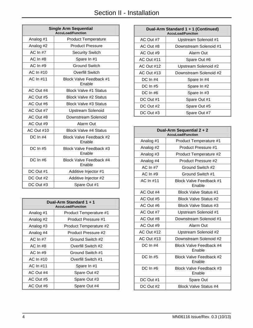
Single Arm Sequential AccuLoad/Function
Analog #1 Product Temperature
Analog #2 Product Pressure
AC In #7 Security Switch
AC In #8 Spare In #1
AC In #9 Ground Switch
AC In #10 Overfill Switch
AC In #11 Block Valve Feedback #1 Enable
AC Out #4 Block Valve #1 Status
AC Out #5 Block Valve #2 Status
AC Out #6 Block Valve #3 Status
AC Out #7 Upstream Solenoid
AC Out #8 Downstream Solenoid
AC Out #9 Alarm Out
AC Out #10 Block Valve #4 Status
DC In #4 Block Valve Feedback #2 Enable
DC In #5 Block Valve Feedback #3 Enable
DC In #6 Block Valve Feedback #4 Enable
DC Out #1 Additive Injector #1
DC Out #2 Additive Injector #2
DC Out #3 Spare Out #1
Dual-Arm Standard 1 + 1 AccuLoad/Function
Analog #1 Product Temperature #1
Analog #2 Product Pressure #1
Analog #3 Product Temperature #2
Analog #4 Product Pressure #2
AC In #7 Ground Switch #2
AC In #8 Overfill Switch #2
AC In #9 Ground Switch #1
AC In #10 Overfill Switch #1
AC In #11 Spare In #1
AC Out #4 Spare Out #2
AC Out #5 Spare Out #3
AC Out #6 Spare Out #4
Dual-Arm Standard 1 + 1 (Continued) AccuLoad/Function
AC Out #7 Upstream Solenoid #1
AC Out #8 Downstream Solenoid #1
AC Out #9 Alarm Out
AC Out #11 Spare Out #6
AC Out #12 Upstream Solenoid #2
AC Out #13 Downstream Solenoid #2
DC In #4 Spare In #4
DC In #5 Spare In #2
DC In #6 Spare In #3
DC Out #1 Spare Out #1
DC Out #2 Spare Out #5
DC Out #3 Spare Out #7
Dual-Arm Sequential 2 + 2 AccuLoad/Function
Analog #1 Product Temperature #1
Analog #2 Product Pressure #1
Analog #3 Product Temperature #2
Analog #4 Product Pressure #2
AC In #7 Ground Switch #2
AC In #9 Ground Switch #1
AC In #11 Block Valve Feedback #1 Enable
AC Out #4 Block Valve Status #1
AC Out #5 Block Valve Status #2
AC Out #6 Block Valve Status #3
AC Out #7 Upstream Solenoid #1
AC Out #8 Downstream Solenoid #1
AC Out #9 Alarm Out
AC Out #12 Upstream Solenoid #2
AC Out #13 Downstream Solenoid #2
DC In #4 Block Valve Feedback #4 Enable
DC In #5 Block Valve Feedback #2 Enable
DC In #6 Block Valve Feedback #3 Enable
DC Out #1 Spare Out
DC Out #2 Block Valve Status #4

Section II – Installation
MN06116 Issue/Rev. 0.3 (10/13) 5
Dual-Arm Sequential 3 + 1 AccuLoad/Function
Analog #1 Product Temperature #1
Analog #2 Product Pressure #1
Analog #3 Product Temperature #2
Analog #4 Product Pressure #2
AC In #7 Ground Switch #2
AC In #8 Overfill Switch #2
AC In #9 Ground Switch #1
AC In #10 Overfill Switch #1
AC In #11 Block Valve Feedback #1 Enable
AC Out #4 Block Valve Status #1
AC Out #5 Block Valve Status #2
AC Out #6 Block Valve Status #3
AC Out #9 Alarm Out
DC In #4 Security Switch
DC In #5 Block Valve Feedback #2 Enable
DC In #6 Block Valve Feedback #3 Enable
DC Out #1 Spare Out #1
DC Out #2 Spare Out #2
Quad-Arm Standard AccuLoad/Function
Analog #1 Product #1 Temperature
Analog #2 Product #2 Temperature
Analog #3 Product #3 Temperature
Analog #4 Product #4 Temperature
AC In #7 Product #2 Ground
AC In #8 Product #2 Overfill
AC In #9 Product #1 Ground
AC In #10 Product #1 Overfill
AC In #11 Spare Input #1
AC In #12 Product #4 Ground
AC In #13 Product #4 Overfill
AC In #14 Product #3 Ground
AC In #15 Product #3 Overfill
AC Out #4 Product #1 Additive Injector #1
AC Out #5 Spare Output #4
AC Out #6 Product #1 Additive Injector #2
Quad-Arm Standard AccuLoad/Function
AC Out #7 Product #1 Upstream Solenoid
AC Out #8 Product #1 Downstream Solenoid
AC Out #9 Alarm #1
AC Out #10 Product #1 Pump
AC Out #11 Spare Output #5
AC Out #12 Product #2 Upstream Solenoid
AC Out #13 Product #2 Downstream Solenoid
AC Out #14 Product #2 Pump
AC Out #15 Spare Output #6
AC Out #16 Spare Output #7
AC Out #17 Spare Output #8
AC Out #18 Product #3 Upstream Solenoid
AC Out #19 Product #3 Downstream Solenoid
AC Out #20 Alarm #2
AC Out #21 Product #3 Pump
AC Out #22 Product #2 Additive Injector #1
AC Out #23 Product #4 Upstream Solenoid
AC Out #24 Product #4 Downstream Solenoid
AC Out #25 Product #4 Pump
AC Out #26 Product #2 Additive Injector #2
AC Out #27 Product #3 Additive Injector #1
AC Out #28 Product #3 Additive Injector #2
AC Out #29 Product #4 Additive Injector #1
AC Out #30 Product #4 Additive Injector #2
DC In #4 Spare Input #4
DC In #5 Spare Input #2
DC In #6 Spare Input #3
DC Out #1 Spare Output #1
DC Out #2 Spare Output #2
DC Out #3 Spare Output #3
BIO DC In/Out #1
Spare BIOB #1
BIO DC In/Out #2
Spare BIOB #2
BIO DC In/Out #3
Spare BIOB #3
BIO DC In/Out #4
Spare BIOB #4

Section II - Installation
6 MN06116 Issue/Rev. 0.3 (10/13)
Quad-Arm Standard AccuLoad/Function
BIO DC In/Out #5
Spare BIOB #5
BIO DC In/Out #6
Spare BIOB #6
BIO DC In/Out #7
Spare BIOB #7
BIO DC In/Out #8
Spare BIOB #8
Dual-Arm Standard and 2-Product Sequential AccuLoad/Function
Analog #1 Arm #1 Product Temperature
Analog #2 Arm #2 Product Temperature
Analog #3 Arm #3 Product Temperature
AC In #7 Arm #2 Ground
AC In #8 Arm #2 Overfill
AC In #9 Arm #1 Ground
AC In #10 Arm #1 Overfill
AC In #11 Spare Input #1
AC In #12 Arm #3 Product #1 Block Valve
Feedback
AC In #13 Arm #3 Product #2 Block Valve
Feedback
AC In #14 Arm #3 Ground
AC In #15 Arm #3 Overfill
AC Out #4 Arm #1 Additive Injector #1
AC Out #5 Spare Output #4
AC Out #6 Arm #1 Additive Injector #2
AC Out #7 Arm #1 Upstream Solenoid
AC Out #8 Arm #1 Downstream Solenoid
AC Out #9 Alarm #1
AC Out #10 Arm #1 Pump
AC Out #11 Spare Output #5
AC Out #12 Arm #2 Upstream Solenoid
AC Out #13 Arm #2 Downstream Solenoid
AC Out #14 Arm #2 Pump
AC Out #15 Spare Output #6
Dual-Arm Standard and 2-Product Sequential AccuLoad/Function
AC Out #16 Spare Output #7
AC Out #17 Spare Output #8
AC Out #18 Arm #3 Upstream Solenoid
AC Out #19 Arm #3 Downstream Solenoid
AC Out #20 Alarm #2
AC Out #21 Arm #3 Product #1 Pump
AC Out #22 Arm #2 Additive Injector #1
AC Out #23 Arm #3 Product #1 Block Valve
AC Out #24 Arm #3 Product #2 Block Valve
AC Out #25 Arm #3 Product #2 Pump
AC Out #26 Arm #2 Additive Injector #2
AC Out #27 Arm #3 Additive Injector #1
AC Out #28 Arm #3 Additive Injector #2
AC Out #29 Arm #3 Additive Injector #3
AC Out #30 Arm #3 Additive Injector #4
DC In #4 Spare Input #4
DC In #5 Spare Input #2
DC In #6 Spare Input #3
DC Out #1 Spare Output #1
DC Out #2 Spare Output #2
DC Out #3 Spare Output #3
BIO DC In/Out #1
Spare BIOB #1
BIO DC In/Out #2
Spare BIOB #2
BIO DC In/Out #3
Spare BIOB #3
BIO DC In/Out #4
Spare BIOB #4
BIO DC In/Out #5
Spare BIOB #5
BIO DC In/Out #6
Spare BIOB #6
BIO DC In/Out #7
Spare BIOB #7
BIO DC In/Out #8
Spare BIOB #8

Section II – Installation
MN06116 Issue/Rev. 0.3 (10/13) 7
4-Product Ratio AccuLoad/Function
Analog #1 Product #1 Temperature
Analog #2 Product #2 Temperature
Analog #3 Product #3 Temperature
Analog #4 Product #4 Temperature
AC In #7 Spare Input #5
AC In #8 Spare Input #6
AC In #9 Ground
AC In #10 Overfill
AC In #11 Spare Input #1
AC In #12 Spare Input #7
AC In #13 Spare Input #8
AC In #14 Spare Input #9
AC In #15 Spare Input #10
AC Out #4 Product #1 Additive Injector #1
AC Out #5 Spare Output #4
AC Out #6 Product #1 Additive Injector #2
AC Out #7 Product #1 Upstream Solenoid
AC Out #8 Product #1 Downstream Solenoid
AC Out #9 Alarm #1
AC Out #10 Product #1 Pump
AC Out #11 Spare Output #5
AC Out #12 Product #2 Upstream Solenoid
AC Out #13 Product #2 Downstream Solenoid
AC Out #14 Product #2 Pump
AC Out #15 Spare Output #6
AC Out #16 Spare Output #7
AC Out #17 Spare Output #8
AC Out #18 Product #3 Upstream Solenoid
AC Out #19 Product #3 Downstream Solenoid
AC Out #20 Alarm #2
AC Out #21 Product #3 Pump
AC Out #22 Product #2 Additive Injector #1
AC Out #23 Product #4 Upstream Solenoid
AC Out #24 Product #4 Downstream Solenoid
AC Out #25 Product #4 Pump
AC Out #26 Product #2 Additive Injector #2
AC Out #27 Product #3 Additive Injector #1
AC Out #28 Product #3 Additive Injector #2
4-Product Ratio AccuLoad/Function
AC Out #29 Product #4 Additive Injector #1
AC Out #30 Product #4 Additive Injector #2
DC In #4 Spare Input #4
DC In #5 Spare Input #2
DC In #6 Spare Input #3
DC Out #1 Spare Output #1
DC Out #2 Spare Output #2
DC Out #3 Spare Output #3
BIO DC In/Out #1
Spare BIOB #1
BIO DC In/Out #2
Spare BIOB #2
BIO DC In/Out #3
Spare BIOB #3
BIO DC In/Out #4
Spare BIOB #4
BIO DC In/Out #5
Spare BIOB #5
BIO DC In/Out #6
Spare BIOB #6
BIO DC In/Out #7
Spare BIOB #7
BIO DC In/Out #8
Spare BIOB #8
Standard and 3-Product Ratio AccuLoad/Function
Analog #1 Arm #1 Product Temperature
Analog #2 Arm #2 Product #1 Temperature
Analog #3 Arm #3 Product #2 Temperature
Analog #4 Arm #2 Product #3 Temperature
AC In #7 Arm #2 Ground
AC In #8 Arm #2 Overfill
AC In #9 Arm #1 Ground
AC In #10 Arm #1 Overfill
AC In #11 Spare Input #1
AC In #12 Spare Input #5
AC In #13 Spare Input #6
AC In #14 Spare Input #7
AC In #15 Spare Input #8

Section II - Installation
8 MN06116 Issue/Rev. 0.3 (10/13)
Standard and 3-Product Ratio AccuLoad/Function
AC Out #4 Arm #1 Additive Injector #1
AC Out #5 Spare Output #4
AC Out #6 Arm #1 Additive Injector #2
AC Out #7 Arm #1 Upstream Solenoid
AC Out #8 Arm #1 Downstream Solenoid
AC Out #9 Alarm #1
AC Out #10 Arm #1 Pump
AC Out #11 Spare Output #5
AC Out #12 Arm #2 Product #1 Upstream Solenoid
AC Out #13 Arm #2 Product #2
Downstream Solenoid
AC Out #14 Arm #2 Product #1 Pump
AC Out #15 Spare Output #6
AC Out #16 Spare Output #7
AC Out #17 Spare Output #8
AC Out #18 Arm #2 Product #2 Upstream Solenoid
AC Out #19 Arm #2 Product #2
Downstream Solenoid
AC Out #20 Alarm #2
AC Out #21 Arm #2 Product #2 Pump
AC Out #22 Arm #2 Product #1 Additive Injector #1
AC Out #23 Arm #2 Product #3 Upstream Solenoid
AC Out #24 Arm #2 Product #3
Downstream Solenoid
AC Out #25 Arm #2 Product #3 Pump
AC Out #26 Arm #2 Product #1 Additive Injector #2
AC Out #27 Arm #2 Product #2 Additive Injector #1
AC Out #28 Arm #2 Product #2 Additive Injector #2
AC Out #29 Arm #2 Product #3 Additive Injector #1
AC Out #30 Arm #2 Product #3 Additive Injector #2
DC In #4 Spare Input #4
DC In #5 Spare Input #2
Standard and 3-Product Ratio AccuLoad/Function
DC In #6 Spare Input #3
DC Out #1 Spare Output #1
DC Out #2 Spare Output #2
DC Out #3 Spare Output #3
BIO DC In/Out #1
Spare BIOB #1
BIO DC In/Out #2
Spare BIOB #2
BIO DC In/Out #3
Spare BIOB #3
BIO DC In/Out #4
Spare BIOB #4
BIO DC In/Out #5
Spare BIOB #5
BIO DC In/Out #6
Spare BIOB #6
BIO DC In/Out #7
Spare BIOB #7
BIO DC In/Out #8
Spare BIOB #8
Six-Product Sequential AccuLoad/Function
Analog #1 Product Temperature
Analog #2 Product Pressure
AC In #7 Spare Input #1
AC In #8 Spare Input #2
AC In #9 Ground
AC In #10 Overfill
AC In #11 Product #1 Block Valve Feedback
AC In #12 Product #5 Block Valve Feedback
AC In #13 Product #6 Block Valve Feedback
AC In #14 Spare Input #3
AC In #15 Spare Input #4
AC Out #4 Product #1 Block Valve
AC Out #5 Product #2 Block Valve
AC Out #6 Product #3 Block Valve
AC Out #7 Upstream Solenoid
AC Out #8 Downstream Solenoid

Section II – Installation
MN06116 Issue/Rev. 0.3 (10/13) 9
Six-Product Sequential AccuLoad/Function
AC Out #9 Alarm #1
AC Out #10 Product #4 Block Valve
AC Out #11 Product #1 Pump
AC Out #12 Product #2 Pump
AC Out #13 Product #3 Pump
AC Out #14 Product #4 Pump
AC Out #15 Product #5
AC Out #16 Product #6 Pump
AC Out #17 Product #5 Block Valve
AC Out #18 Product #6 Block Valve
AC Out #19 Spare Output #2
AC Out #20 Alarm #2
AC Out #21 Spare Output #3
AC Out #22 Spare Output #4
AC Out #23 Spare Output #5
AC Out #24 Spare Output #6
AC Out #25 Spare Output #7
AC Out #26 Spare Output #8
AC Out #27 Spare Output #9
AC Out #28 Spare Output #10
AC Out #29 Additive Injector #3
AC Out #30 Additive Injector #4
DC Out #1 Additive Injector #1
DC Out #2 Additive Injector #2
DC Out #3 Spare Output #1
DC In #4 Product #2 Block Valve Feedback
DC In #5 Product #3 Block Valve Feedback
DC In #6 Product #4 Block Valve Feedback
BIO DC In/Out #1
Spare BIOB #1
BIO DC In/Out #2
Spare BIOB #2
BIO DC In/Out #3
Spare BIOB #3
BIO DC In/Out #4
Spare BIOB #4
BIO DC In/Out #5
Spare BIOB #5
Six-Product Sequential AccuLoad/Function
BIO DC In/Out #6
Spare BIOB #6
BIO DC In/Out #7
Spare BIOB #7
BIO DC In/Out #8
Spare BIOB #8
Analog Inputs, Single Arm Standard AccuLoad/Function
1 Input – Not defined
2 Input 4-20 mA Temperature 4mA = -4.4 deg F, 20mA = 98 deg F. (4mA = -17.2 C., 20mA = 34.0 deg C.)
3 Input 4-20 mA Pressure 4mA = 32.8 PSI, 20mA = 84 PSI (4mA = 2.28 kg/cm2, 20mA = 7.4 kg/cm2)
4 Input 4-20 mA Density 4mA = 696 kg/M3, 20mA = 1080 kg/M3 (4mA = 696 kg/M3, 20mA = 1080 kg/M3)
5 Input – Not defined
6 Input – Not defined
Analog Inputs, Single Arm Ratio AccuLoad/Function
1 Arm #1 Temperature Input 4-20 mA, 4mA = -4.4 deg F, 20mA = 98 deg F. (4mA = -17.2 C., 20mA = 34.0 deg C.)
2 Arm #1 Pressure Input 4-20 mA, 4mA = 32.8 PSI, 20mA = 84 PSI (4mA = 2.28 kg/cm2, 20mA = 7.4 kg/cm2)
3 Arm #1 Temperature Input 4-20 mA, 4mA = -4.4 deg F, 20mA = 98 deg F. (4mA = -17.2 C., 20mA = 34.0 deg C.)
4 Arm #1 Pressure Input 4-20 mA, 4mA = 32.8 PSI, 20mA = 84 PSI (4mA = 2.28 kg/cm2, 20mA = 7.4 kg/cm2)
5 Input – Not defined
6 Input – Not defined

Section II - Installation
10 MN06116 Issue/Rev. 0.3 (10/13)
Analog Inputs, Single Arm Sequential AccuLoad/Function
1 Arm #1 Temperature Input 4-20 mA, 4mA = -4.4 deg F, 20mA = 98 deg F. (4mA = -17.2 C., 20mA = 34.0 deg C.)
2 Arm #1 Pressure Input 4-20 mA, 4mA = 32.8 PSI, 20mA = 84 PSI (4mA = 2.28 kg/cm2, 20mA = 7.4 kg/cm2)
3 Input – Not defined
4 Input – Not defined
5 Input – Not defined
6 Input – Not defined
Analog Inputs, Dual-Arm Standard 1 + 1 AccuLoad/Function
1 Arm #1 Temperature Input 4-20 mA, 4mA = -4.4 deg F, 20mA = 98 deg F. (4mA = -17.2 C., 20mA = 34.0 deg C.)
2 Arm #1 Pressure Input 4-20 mA, 4mA = 32.8 PSI, 20mA = 84 PSI (4mA = 2.28 kg/cm2, 20mA = 7.4 kg/cm2)
3 Arm #2 Temperature Input 4-20 mA, 4mA = -4.4 deg F, 20mA = 98 deg F. (4mA = -17.2 C., 20mA = 34.0 deg C.)
4 Arm #2 Pressure Input 4-20 mA, 4mA = 32.8 PSI, 20mA = 84 PSI (4mA = 2.28 kg/cm2, 20mA = 7.4 kg/cm2)
5 Input – Not defined
6 Input – Not defined
Analog Inputs, Dual Arm Sequential 2 + 2 AccuLoad/Function
1 Arm #1 Temperature Input 4-20 mA, 4mA = -4.4 deg F, 20mA = 98 deg F. (4mA = -17.2 C., 20mA = 34.0 deg C.)
2 Arm #1 Pressure Input 4-20 mA, 4mA = 32.8 PSI, 20mA = 84 PSI (4mA = 2.28 kg/cm2, 20mA = 7.4 kg/cm2)
3 Arm #2 Temperature Input 4-20 mA, 4mA = -4.4 deg F, 20mA = 98 deg F. (4mA = -17.2 C., 20mA = 34.0 deg C.)
4 Arm #2 Pressure Input 4-20 mA, 4mA = 32.8 PSI, 20mA = 84 PSI (4mA = 2.28 kg/cm2, 20mA = 7.4 kg/cm2)
5 Input – Not defined
6 Input – Not defined
Analog Inputs, Dual-Arm Sequential 3 + 1 AccuLoad/Function
1 Arm #1 Temperature Input 4-20 mA, 4mA = -4.4 deg F, 20mA = 98 deg F. (4mA = -17.2 C., 20mA = 34.0 deg C.)
2 Arm #1 Pressure Input 4-20 mA, 4mA = 32.8 PSI, 20mA = 84 PSI (4mA = 2.28 kg/cm2, 20mA = 7.4 kg/cm2)
3 Arm #2 Temperature Input 4-20, mA, 4mA = -4.4 deg F, 20mA = 98 deg F. (4mA = -17.2 C., 20mA = 34.0 deg C.)
4 Arm #2 Pressure Input 4-20 mA, 4mA = 32.8 PSI, 20mA = 84 PSI (4mA = 2.28 kg/cm2, 20mA = 7.4 kg/cm2)
5 Input – Not defined
6 Input – Not defined
Analog Inputs, Quad Standard AccuLoad/Function
1 Arm #1 Product #1 Temperature Input 4-20 mA, 4mA = -4.4 deg F, 20mA = 98 deg F. (4mA = -17.2 C., 20mA = 34.0 deg C.)
2 Arm #2 Product #2 Temperature Input 4-20 mA, 4mA = -4.4 deg F, 20mA = 98 deg F. (4mA = -17.2 C., 20mA = 34.0 deg C.)
3 Arm #3 Product #3 Temperature Input 4-20 mA, 4mA = -4.4 deg F, 20mA = 98 deg F. (4mA = -17.2 C., 20mA = 34.0 deg C.)
4 Arm #4 Product #4 Temperature Input 4-20 mA, 4mA = -4.4 deg F, 20mA = 98 deg F. (4mA = -17.2 C., 20mA = 34.0 deg C.)
5 Input – Not defined
6 Input – Not defined

Section II – Installation
MN06116 Issue/Rev. 0.3 (10/13) 11
Analog Inputs, Dual Standard and
2-Product Sequential AccuLoad/Function
1 Arm #1 Product Temperature Input 4-20 mA, 4mA = -4.4 deg F, 20mA = 98 deg F. (4mA = -17.2 C., 20mA = 34.0 deg C.)
2 Arm #2 Product Temperature Input 4-20 mA, 4mA = -4.4 deg F, 20mA = 98 deg F. (4mA = -17.2 C., 20mA = 34.0 deg C.)
3 Arm #3 Product Temperature Input 4-20 mA, 4mA = -4.4 deg F, 20mA = 98 deg F. (4mA = -17.2 C., 20mA = 34.0 deg C.)
4 Input – Not defined
5 Input – Not defined
6 Input – Not defined
Analog Inputs, 4-Product Ratio AccuLoad/Function
1 Product #1 Temperature Input 4-20 mA, 4mA = -4.4 deg F, 20mA = 98 deg F. (4mA = -17.2 C., 20mA = 34.0 deg C.)
2 Product #2 Temperature Input 4-20 mA, 4mA = -4.4 deg F, 20mA = 98 deg F. (4mA = -17.2 C., 20mA = 34.0 deg C.)
3 Product #3 Temperature Input 4-20 mA, 4mA = -4.4 deg F, 20mA = 98 deg F. (4mA = -17.2 C., 20mA = 34.0 deg C.)
4 Product #4 Temperature Input 4-20 mA, 4mA = -4.4 deg F, 20mA = 98 deg F. (4mA = -17.2 C., 20mA = 34.0 deg C.)
5 Input – Not defined
6 Input – Not defined
Analog Inputs, Standard and 3-Product Ratio AccuLoad/Function
1 Arm #1 Product Temperature Input 4-20 mA, 4mA = -4.4 deg F, 20mA = 98 deg F. (4mA = -17.2 C., 20mA = 34.0 deg C.)
2 Arm #2 Product #1 Temperature Input 4-20 mA, 4mA = -4.4 deg F, 20mA = 98 deg F. (4mA = -17.2 C., 20mA = 34.0 deg C.)
3 Arm #2 Product #2 Temperature Input 4-20 mA, 4mA = -4.4 deg F, 20mA = 98 deg F. (4mA = -17.2 C., 20mA = 34.0 deg C.)
4 Arm #2 Product #3 Temperature Input 4-20 mA, 4mA = -4.4 deg F, 20mA = 98 deg F. (4mA = -17.2 C., 20mA = 34.0 deg C.)
5 Input – Not defined
6 Input – Not defined
Analog Inputs, 6-Product Sequential AccuLoad/Function
1 Product Temperature Input 4-20 mA, 4mA = -4.4 deg F, 20mA = 98 deg F. (4mA = -17.2 C., 20mA = 34.0 deg C.)
2 Product Pressure Input 4-20 mA, 4mA = 32.8 PSI, 20mA = 84 PSI (4mA = 2.28 kg/cm2, 20mA = 7.4 kg/cm2)
3 Input – Not defined
4 Input – Not defined
5 Input – Not defined
6 Input – Not defined
Note: Temperature, pressure, and density settings are shown in Imperial Units, with Metric Units in parentheses.

Section II - Installation
12 MN06116 Issue/Rev. 0.3 (10/13)
Figure 1. EAAI Board
Simulator Board
Prom (U8)
Jumpers

Section II – Installation
MN06116 Issue/Rev. 0.3 (10/13) 13
Figure 2. BSE Board
Prom (U5)
Cable for VLR
Simulation (TB14)
Simulator Board

Section III - Operation
14 MN06116 Issue/Rev. 0.3 (10/13)
After the VLR Simulator has been installed on the PC and the PC is wired to the AccuLoad III, the sys-tem is ready to operate. If the AccuLoad III is not yet programmed either manually through the keypad or through the AccuMate that was provided with the demo unit, download one of the VLR programs to the AccuLoad III.
The system is now ready for operation. Press the SET key on the keypad while the AccuLoad is in RUN mode. The AccuLoad will prompt the operator to set a batch on the AccuLoad III. After the batch has been preset, press the START key to initiate the loading process. With the PC volume on, you will hear the simulator start loading the truck. In addition to sound, the simulator will indicate loading via a pulse counter and lights on the control valve that change to green denoting the solenoid operation on the valve.
Each simulated configuration on the VLR has its own set of switches that can be turned on and off using the mouse. Possible switches include Weights and Measures (W&M); Program Enable Relay (PE); spare inputs and outputs; security; and ground and overfill switches. Also available with some configura-tions are one or two alarms, and temperature, pres-sure, and density indicators. The table below indi-cates the primary indicators available on each of the configuration screens. Note that all Quad configura-tions include eight BIOB DC input/output switches, in addition to those switches shown on the table.
On those screens with temperature, pressure, and density indicators, increase or decrease the readings by clicking the needles with the mouse and dragging them to new positions on the dials. These can be used to simulate high and low alarms, or to show a change in the factors used for compensation.
W&M PE
Spare
Inputs Ground Overfill Security
Spare
Outputs Temp Pressure Density Alarms
Single Arm Standard 1 1 2 1 1 -- 5 1 1 1 2
Single Arm Ratio -- -- 3 1 1 1 3 2 2 -- 1
Single Arm Sequential -- -- 1 1 1 1 1 1 1 -- 1
Dual Arm Standard 1 + 1 -- -- 4 2 2 -- 7 2 2 -- 1
Dual Arm Sequential 2 + 2 -- -- 1 2 2 -- -- 2 2 -- 1
Dual Arm Sequential 3 + 1 -- -- -- 2 2 1 2 2 2 -- 1
Quad Arm Standard -- -- 4 4 4 -- 8 4 -- -- 2
Dual Standard +
2-Product Sequential -- -- 4 3 3 -- 8 3 -- -- 2
4-Product Ratio -- -- 10 1 1 -- 8 4 -- -- 2
Standard + 3-Product Ratio -- -- 8 2 2 -- 8 4 -- -- 2
6-Product Sequential -- -- 4 1 1 -- 10 1 1 -- 2
Figure 3 Click the "Configuration" button at the upper left-hand corner of the simulator display to set up sounds and dynam-ics for the system, a flow echo strip chart, and the communication port to be used by the computer. Metric units are selectable only on the ALS1 and ALD1 configurations.
From the "Sounds" dialog box, the simulator can be set up to allow the sound of the meter turning to accompany flow. "Click Sound Enable" adds the sound of valve solenoids clicking on and off as these actions occur. "Audible Alarm Enable" provides the sound of an alarm as it occurs. These settings will not be active until the "Apply" or "OK" button is clicked. Select "OK" to leave the screen.

Section III – Operation
MN06116 Issue/Rev. 0.3 (10/13) 15
Figure 4
The "System Dynamics" display allows the operator to set the Valve Time Constant. The Valve Time Constant de-fault is 0.875, which allows for smooth valve opening and closing. Change valve opening and closing speeds by adjusting this factor. The higher the factor, the more quickly the valve responds to commands to open and close. Again, changing these settings will not take effect until the "Apply" or "OK" button has been clicked with the mouse. Press "OK" to leave the screen.
Figure 5
The "Misc." (Miscellaneous) dialog box shown in Figure 6 below allows the operator to set the simulator to display a flow rate strip chart, change to metric units, and select the communication port out of the PC. (Ensure that the communication port in use is configured for the same baud rate as the VLR.) The chart will indicate the changes in flow rate as they occur when the AccuLoad III is running. The dialog box in Figure is applicable only to ALS1 and ALD1 configurations; the Quad box is identical, except that there is no option for metric selection. Selecting metric units in the simulator changes the scales and units. The AccuLoad III should also be changed to metric units, either through the keypad or through the AccuMate. Changes are not complete without using the mouse to click on the "Apply" or "OK" button. Click on "OK" to close the dialog box.

Section III - Operation
16 MN06116 Issue/Rev. 0.3 (10/13)
Figure 6
Note that in the lower left-hand corner the window is a “Communication Status” dialog. This will inform the user if the AccuLoad is communicating with the PC. If the communication port selected in the VLR is not the communica-tion port that is being used, the status will show “Comm Port -- Not available” and the two board communication status boxes will appear in red as shown in Figure 7 below.
Figure 7
If there is an error in hardware communications, the status will show “Not Communicating” and the two board communication status boxes will appear in red as shown in Figure 8 below. It is also possible to use the simulator in an offline mode, in which case the message will appear as “Not Communicating”.
Figure 8
If the AccuLoad and VLR are communicating, the status will show “Communications Established” and the two board communication status boxes will appear in green as shown in Figure 9 below.
Figure 9

Section III – Operation
MN06116 Issue/Rev. 0.3 (10/13) 17
The figure below displays the flow rate recorder, the number of meter pulses that have been output by the meter, and the current flow rate in GPM. Valves may be manually opened to simulate product flow.
Figure 10
Also available on some of the simulator displays is the ability to induce pulse errors and to cause additive injector errors. Clicking and holding the mouse on either of the buttons will induce errors in the system. If the AccuLoad is programmed to alarm on these errors, an alarm will occur. If a relay is set up in the AccuLoad III for alarm output, the alarm will appear on the AccuLoad III display and the simulator Alarm 1 will light, indicating an alarm in the system.

Section VI – Related Publications
The following literature can be obtained from FMC Technologies Measurement Solutions Literature Fulfillment at [email protected] or online at www.fmctechnologies.com/measurementsolutions. When requesting literature from Literature Fulfillment, please reference the appropriate bulletin number and title.
AccuLoad IIIInstallation (w/ ALX Firmware) .........................................................................................................Bulletin MN06135Installation (SA) ...............................................................................................................................Bulletin MN06140Installation (N4) ...............................................................................................................................Bulletin MN06143Operator Reference .........................................................................................................................Bulletin MN06129Operator Reference (SA).................................................................................................................Bulletin MN06139Communications ............................................................................................................................Bulletin MN06130LModbus Communications (ALX) ....................................................................................................Bulletin MN06131LModbus Communications (ALS) .................................................................................................... Bulletin MN06111LSpecification .................................................................................................................................... Bulletin SS06036Specification (SA) ............................................................................................................................ Bulletin SS06039Specification (N4) ............................................................................................................................ Bulletin SS06041
AccuMate for AccuLoad III Installation/Operation.......................................................................................................................Bulletin MN06136Specifications .................................................................................................................................. Bulletin SS06032 AccuLoad III UpgradeSpecification .................................................................................................................................... Bulletin SS06033Upgrade Specification AccuLoad II to III.......................................................................................... Bulletin SS06043Upgrade Installation/Operation - AccuLoad II to III ..........................................................................Bulletin MN06145Upgrade Installation - AccuLoad I to III............................................................................................Bulletin MN06115
Revisions included in MN06116 Issue/Rev. 0.3 (10/13): Updated images throughout the document. Added Figures 8, 9, and 10.
Printed in U.S.A. © 10/13 FMC Technologies Measurement Solutions, Inc. All rights reserved. MN06116 Issue/Rev. 0.3 (10/13)
www.fmctechnologies.com/measurementsolutions
The specifications contained herein are subject to change without notice and any user of said specifications should verify from the manufacturer that the specifications are currently in effect. Otherwise, the manufacturer assumes no responsibility for the use of specifications which may have been changed and are no longer in effect.
Contact information is subject to change. For the most current contact information, visit our website at www.fmctechnologies.com/measurementsolutions and click on the “Contact Us” link in the left-hand column.
Headquarters:500 North Sam Houston Parkway West, Suite 100, Houston, TX 77067 USA Phone: +1 (281) 260 2190 Fax: +1 (281) 260 2191
Ellerbek, Germany +49 (4101) 3040Erie, PA USA +1 (814) 898 5000
Integrated Measurement Systems:Corpus Christi, TX USA +1 (361) 289 3400Kongsberg, Norway +47 (32) 286700
Operations: Measurement Products and Equipment: