SMF stem - Surgical Devices and Advanced Wound Care ... Table of contents Introduction 4...
32
SMF stem North America Edition Surgical Technique
Transcript of SMF stem - Surgical Devices and Advanced Wound Care ... Table of contents Introduction 4...

SMF stem
North America Edition
Surgical Technique

Nota Bene: The technique description herein is made available to the healthcare professional to illustrate the authors’ suggested treatment for the uncomplicated procedure. In the final analysis, the preferred treatment is that which addresses the needs of the patient.
Design surgeon list
Smith & Nephew Orthopaedics would like to thank the following surgeons who were instrumental in the design and refinement of the SMF™ Short Modular Femoral Hip System.
Kristaps Keggi, MD Yale Medical Center New Haven, CT Waterbury Hospital Waterbury, CT
Prof Francesco Biggi, MD Ospedale San Martino di Belluno Belluno, Italy Prof Rolf Haaker, MD St Vincenz Hospital Brakel, Germany Prof Norbert Linder, MD Brüderkrankenhaus St Josef Paderborn, Germany
Todd Swanson, MD Centennial Hospital Las Vegas, NV
Prof Francesco Falez, MD Ospedale Santo Spirito Rome, Italy
Prof Thomas Hess, MD Dreifaltigkeits-Hospital Lippstadt, Germany

3
Table of contents
Introduction . . . . . . . . . . . . . . . . . . . . . . . . . . . 4
Preoperative planning . . . . . . . . . . . . . . . . . . . 5
Summary of modular neck options . . . . . . . . . 7
Surgical technique . . . . . . . . . . . . . . . . . . . . . 10
Stem specifications . . . . . . . . . . . . . . . . . . . . 19
Instrument layout . . . . . . . . . . . . . . . . . . . . . . 21
Catalog information . . . . . . . . . . . . . . . . . . . .23
Important information. . . . . . . . . . . . . . . . . . . 27

4
The Short Modular Femoral System (SMF™) is a total hip system consisting of proximally porous coated titanium alloy (Ti-6Al-4V) tapered femoral hip stems with optimized and easy to use instrumentation. It offers the surgeon an improved bone conserving modular neck implant that is compatible with high demand femoral head bearing options from Smith & Nephew. The SMF hip stem is shorter than conventional hip stems, which allows the stem to conserve more of the patient’s femur than other prostheses. The SMF hip stem allows for a slightly higher neck resection. The proximal porous coating of the stem consists of STIKTITE™ Porous Coating, a commercially pure Titanium coating, and is designed to have a press-fit relative to the broach of approximately 1/4mm. The stems are proportionally sized and shaped in sizes 1 through 6, with optional larger sizes 7 through 9. The stems are compatible with four modular neck options that create seven distinct neck positions to address patient anatomy. The SMF system provides modular necks which are manufactured from Cobalt Chrome alloy (CoCr) and are available in standard and high offset plus left and right anteverted options. With various head options from Smith & Nephew, the modular necks allow adjustment of the head center to as many as 42 distinct head center locations.
The SMF stem components are indicated for uncemented use in individuals undergoing primary and revision surgery where other treatments or devices have failed in rehabilitating hips damaged as a result of trauma, inflammatory joint disease such as rheumatoid arthritis, or noninflammatory degenerative joint disease (NIDJD) or any of its composite diagnoses such as osteoarthritis; avascular necrosis; traumatic arthritis; slipped capital epiphysis; fused hip; fracture of the pelvis; diastrophic variant; nonunion, femoral neck fracture and trochanteric fractures of the proximal femur with head involvement that are unmanageable using other techniques; femoral osteotomy, or Girdlestone resection; fracture dislocation of the hip; and correction of deformity.
Introduction
5
The goal of preoperative planning is to determine the correct stem size, level of the femoral neck cut and proper head, modular neck (if appropriate) and stem offset combination. Preoperative templating requires at least an anteroposterior (AP) radiograph of the pelvis and a lateral radiograph of the affected hip. If the opposite hip is unaffected by disease, it can often provide accurate sizing information for the femoral stem.
To determine if a patient has a leg length discrepancy, the AP radiograph should be used. Draw a line tangential to both of the Ischia or both of the obturator foramens as shown in Figure 1. This line should extend out until it contacts the medial cortex of bone on both femurs. If the patient’s legs are of equal length, the line that has been drawn will contact both femurs at the same level. If the patient’s legs are of unequal length, the lines will contact the femurs at different levels along the femur, such as the bottom of the lesser trochanter. The distance between the line that has been drawn and the reference point on both femurs is measured. The difference in these measurements indicates the patient’s leg length discrepancy.
Nota Bene: The technique description herein is made available to the healthcare professional to illustrate the authors’ suggested treatment for the uncomplicated procedure. In the final analysis, the preferred treatment is that which addresses the needs of the patient.
Note: Using this method of templating for leg length discrepancy assumes the patient has a normal, symmetrical pelvis and has neutral limb positioning.
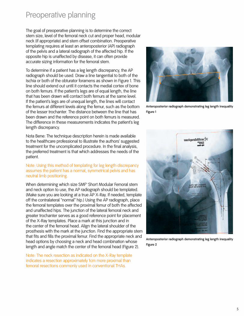
When determining which size SMF™ Short Modular Femoral stem and neck option to use, the AP radiograph should be templated. (Make sure you are looking at a true AP X-Ray. If needed, template off the contralateral “normal” hip.) Using the AP radiograph, place the femoral templates over the proximal femur of both the affected and unaffected hips. The junction of the lateral femoral neck and greater trochanter serves as a good reference point for placement of the X-Ray templates. Place a mark at this junction and in the center of the femoral head. Align the lateral shoulder of the prosthesis with the mark at the junction. Find the appropriate stem that fits and fills the proximal femur. Find the appropriate neck and head options by choosing a neck and head combination whose length and angle match the center of the femoral head (Figure 2).
Note: The neck resection as indicated on the X-Ray template indicates a resection approximately 1cm more proximal than femoral resections commonly used in conventional THAs.
Preoperative planning
Anteroposterior radiograph demonstrating leg length inequality
Figure 2
Anteroposterior radiograph demonstrating leg length inequality
Figure 1

6
Note: The SMF™ stem was designed such that the lateral aspect of the stem should be in direct contact with lateral aspect of the femur as shown in Figure 3. The design of the implant is such that the distal medial aspect of the stem does not contact the medial side of the femoral cortex. The stem, when placed in the neutral position, appears to be in slight varus relative to the proximal femoral canal axis (see Figure 4). The current X-Ray templates provide both an extended lateral cortex line and femoral canal axis line to aid in positioning the femoral implant relative to the patient X-Ray during preoperative planning.
If the implant is positioned such that the distal tip is centered in the femoral canal, the lateral aspect of the stem will not be against the lateral cortex, and there is a strong possibility that the stem will rotate until it makes contact with the lateral cortex.
Lateral cortex
Femoral axis
Preoperative planning
Figure 3
Figure 4

7
Four modular neck options are available: standard offset, high offset, left anteverted and right anteverted.
• Neutral necks (0° anteversion) are available in standard and high offset.
• The standard neutral neck has a neck shaft angle of 131° (Figure 5).
• The high offset neutral neck provides 8mm of lateralization. The high offset neck has a neck shaft angle of 125° and 137° when inserted in the reverse/valgus orientation (Figure 6).
• Left anteverted necks shift the femoral head, 10°, anteriorly relative to the stem on a left hip and posteriorly relative to the stem on a right hip. Right anteverted necks shift the femoral head center based on the operative leg in an equivalant manner (Figure 7).
• The anteverted necks are available in one offset option providing 6mm of lateralization relative to the standard offset neck.
• The anteverted neck has a neck shaft angle of 125° and an angle of 137° when inserted in the reverse/valgus orientation.
Summary of modular neck options Applicable to SMF™ stems size 1 through 9 (Also reference table on page 9)
Standard High offset High offset reverse/valgus
Right Right reverse/valgus Left Left reverse/valgus
Figure 5 Figure 6
Figure 7

8
The high offset and anteverted neck are asymetrical and different – offset, leg length and valgus angles can be achieved depending upon orientation of the neck as depicted in the chart on page 9.
To insure that the desired orientation is achieved, the face of the taper of the modular necks are etched with “HO” for High Offset, “L” for Left Anteverted, “R” for Right Anteverted and an arrow which aids in duplicating orientation of the trial modular neck with the implanted modular neck.
When the arrow points top, in the direction of the greater trochanter, the necks provide the options as labeled. If the arrow points to the distal femur, then different head center locations are possible as highlighted on page 9.
Additionally, color coding of the anteverted neck implant packaging and corresponding plastic trial necks has been provided as follows (Figure 10):
High offset neck in varus orientation
Figure 8
Figure 10
Figure 9
High offset neck in reverse/valgus orientation
Laser etch on Top of high offset and left and right anteverted necks
Summary of modular neck options
Sample of Color Coding on Package Labels for Left and Right Anteverted Modular Necks
9
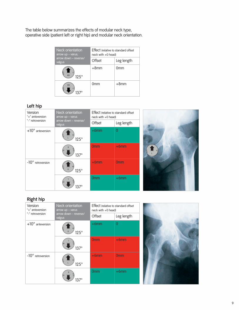
Neck orientationarrow up – varus;arrow down – reverse/valgus
Effect (relative to standard offset neck with +0 head)
Offset Leg length
125°
+8mm 0mm
137°
0mm +8mm
Left hipVersion“+” anteversion“-” retroversion
Neck orientationarrow up – varusarrow down – reverse/valgus
Effect (relative to standard offset neck with +0 head)
Offset Leg length
+10° anteversion
125°
+6mm 0
137°
0mm +6mm
-10° retroversion
125°
+6mm 0mm
137°
0mm +6mm
Right hipVersion“+” anteversion“-” retroversion
Neck orientationarrow up – varusarrow down – reverse/valgus
Effect (relative to standard offset neck with +0 head)
Offset Leg length
+10° anteversion
125°
+6mm 0
137°
0mm +6mm
-10° retroversion
125°
+6mm 0mm
137°
0mm +6mm
The table below summarizes the effects of modular neck type, operative side (patient left or right hip) and modular neck orientation.

10
Surgical technique
The SMF™ stem hip may be implanted through all typical surgical approaches for total hip arthroplasty.
Before surgery, review instrument sets to ensure all instruments are present and working properly.
Femoral osteotomy
Note: The SMF hip stem is designed with an approximately 5–10mm higher neck cut than typical stems, preoperative templating of the proper neck resection level to achieve appropriate leg length is important.
Assemble the osteotomy guide to the broach anteversion handle. Reference marks are provided on the guide in the medial arc for referencing the lesser trochanter and above the proximal shoulder for referencing the tip of greater trochanter. Align the distal axis of the guide with the center of femur and use the reference marks to position the guide to the location identified during templating. The point of the femoral neck resection can be marked with electrocautery corresponding to both the preoperative templating and the intraoperative measurement.
Osteotomize the femoral neck.

11
Prepare acetabulum
If acetabular reconstruction is required, prepare the acetabulum using the surgical technique for the intended Smith & Nephew acetabular component.
Femoral canal preparation
Use the box osteotome and canal finder for initial entry into femoral canal.
Sink the canal finder to the proof mark as shown in Figure 12.
Note: In order to achieve proper stem alignment, it is important to stay lateral with the box osteotome and the canal finder. Care should be taken to ensure that the initial reaming tract is in neutral alignment with the femoral axis, i.e. along the lateral side of the canal (Figure 12).
Figure 12
Figure 11

12
Notch
Broach assembly/disassembly
Smith & Nephew makes available a variety of broach handles to accommodate the various surgical approaches to the hip. All of the broach handles listed utilize the same connection to Smith & Nephew standard broach post and are assembled and disassembled as described below.
Important: Broach handles, as well as all surgical instruments used for the implantation of the SMF™ system, must be cleaned and sterilized before every case in accordance with facility policy and regulations.
Assemble the broach to the broach handle by placing the broach post in the clamp as shown in the figure to the right. Verify that the notch in the broach post is properly aligned with the handle (Figure 13). Use the thumb to lock the clamp onto the broach (Figure 14). A modular anteversion handle can be assembled to the broach handle to provide version control. Disassemble the broach from the broach handle by lifting the lever to release the handle from the broach post.
Caution: Failure to properly align the broach before closing the handle will damage the handle. Damaging the handle may cause extended surgical time or may force the user to use another broach handle that is not as well suited for the surgical approach.
Straight Broach Handle 7136-4021
Single Offset Broach Handle 7136-5703
Double Offset Broach Handle 7136-0089 (Left) 7136-0090 (Right)
Figure 13
Figure 14
Surgical technique

13
Femoral broaching
Start the broaching procedure with the smallest available starter broach. Sequential broaching should then be carried out to the templated stem size. Note that the starter, size -1, size 0 and size 1 broaches all have more aggressive teeth to aid in the initial broaching process. Taking care to preserve the greater trochanter, the starter broach can be used to rasp laterally beneath the greater trochanter. The lateralization of the broaches is important in achieving the aforementioned neutral alignment as shown in Figure 15a. Be sure to check the stability of the broach rotationally, medially and laterally. When broaching keep the version constant. Stop broaching only when the desired level or stability is achieved. It is important to maintain broach rotation due to the rectangular geometry of the implant. For proper sizing and alignment of the broach, it is often necessary to remove bone in the posterior-lateral area of the neck as shown in Figure 15b.
Note: Care should be taken not to force a broach that is too large into the femur. Consideration should be given to using a stem one size smaller than the size templated if the final broach is difficult to seat. This helps avoid intraoperative fractures of the femur.
Note: Optional use of the broach anteversion handle may be helpful for broach/stem extraction when using the double offset broach handles.
Calcar preparation (optional)
With the final broach fully seated, remove the broach handle. Place the calcar reamer over the post of the broach and machine the femoral neck, ensuring alignment to avoid femoral fracture (Figure 16).
Figure 15a
Figure 16
Figure 15b
Posterior lateral neck removal

14
Initial Trial reduction
Broach trial necks are provided to aid in trial reduction before the final stem implant is inserted. Because the broach trial neck geometries can only be placed on the broach in one orientation, a total of seven broach trial necks are necessary to approximate the seven distinct neck positions provided by the modular neck implants, ie varus or valgus positioning of the high offset and left or right anteverted necks. As mentioned previously, the broach trial necks are laseretched with an orientation arrow and neck designation (HO, L or R) to aid in proper orientation as shown to the right.
Place the broach trial neck as determined by preoperative templating onto the broach post (see specification table on page 9 for orientation). Select the trial femoral head of desired diameter and neck length and place onto the trial neck (Figure 17).Reduce the hip and re-measure leg length. Compare to previous measurements recorded from preoperative templating or leg length before dislocation. Adjustments in neck length and/ or offset can be made at this time. If trialing for a Unipolar or Bipolar, trial according to the appropriate technique for the selected device.
Trial reductionReduce the hip and evaluate in the following ways:
Soft tissue tension Some shuck is normal when applying a longitudinal distraction force to the hip. Shuck should not be excessive and the hip should not dislocate in straight traction (Figure 18).
Anterior stability Place the leg in full adduction and hyperextension, while exerting an external rotation force. If the hip cannot be fully extended, it may be too tight. If it dislocates easily, it is too loose and impingement must be addressed or component malposition exists (Figure 19).
Posterior stability Place the leg in adduction and 90° flexion. Gradually rotate internally. The hip should be stable with 45° of internal rotation. If it dislocates with minimal internal rotation, it is too loose and impingement must be addressed or component malposition exists (Figure 20).
Sleep position Place the leg in the “sleep position” with the operated leg semiflexed, adducted and internally rotated over the other leg. Apply axial force to try and dislocate the hip. This position represents a dangerously unstable position that may be adopted by a patient sleeping on their nonoperated side. Once a well-balanced hip has been created with the appropriate trial head and neck, remove the broach (Figure 21).
Soft tissue tension
Figure 17
Figure 18
Sleep position
Figure 21
Surgical technique
Anterior stability
Figure 19
Posterior stability
Figure 20

15
For modular stem insertion Assemble the stem inserter/extractor to the broach handle by placing the stem inserter/extractor post in the clamp (Figure 22). Use the thumb to lock the clamp onto the stem inserter/extractor.
Shown using optional offset broach handle 7136-5703.
Stand the broach handle upright so that the stem inserter/extractor is pointed up. The stem is packaged with a plastic taper protector (Figure 23). Slide the stem into position with the flange of the plastic taper protector engaged in the slot of the stem inserter/extractor. Support the stem until attachment of the screw for rigid insertion or insertion of the stem into the femur when not using the screw to guard against dropping the stem.
For a rigid stem insertion, insert the screw provided in the instrument case through the hole in the stem inserter/extractor and thread the screw all the way down (Figure 24). Use a 3.5mm hex screwdriver to tighten further if desired. Reference straight screwdriver shaft (Cat No 7136-2293) and ratchet driver (Cat No 7136-2294) or T handle (Cat No 7136-4006) to tighten the insertion screw.
Note: Rigid insertion is recommended because it allows for better control of stem version. Rigid insertion is also recommended when using the double offset broach handles.
For non-rigid insertion, proceed to insertion of the stem (Figure 25).
Figure 22
Figure 23
Figure 24 Figure 25
Non-rigid Rigid
Surgical technique
TaperProtector

16
Use gentle mallet blows with valgus force on the inserter to seat the stem to the position of the neck resection (Figure 26). Check the stem stability. If the implant has stopped moving with gentle mallet blows and is not completely seated, remove the stem and repeat the same size broaching steps.
Caution: Do not use excessive force to seat the stem as this may result in femoral fractures or damge to the instrumentation.
Note: Upon final seating of the implant, remove the locking screw (Figure 27) and employ the use of a rolling motion away from the greater trochanter. This will remove all instruments, including the plastic plug, and leave only the stem in place.
Caution: Make certain the plastic plug is removed from the taper before attempting to trial or implant a neck. The plastic plug must be removed from the wound prior to closure.
Trial reduction Once the definitive femoral implant has been inserted, a trial reduction may be performed at this time using the color coded plastic trial necks (Figure 28) and femoral trial heads to obtain leg length, offset and impingement-free range of motion. See specification table on page 9 for details. As an aid to achieving the desired neck orientation and offset, make note of the final trial neck orientation arrow (if using a high offset or anteverted neck) and color of trial neck (if using an anteverted neck).
Caution: Do not use the metallic broach trial necks with the implant as this may cause damage to the implant pocket. Only plastic trial necks should be used for trial reductions with the implant. Damage to the pocket may limit the life of the implant.
Caution: Trial necks are not implantable and must be removed before implanting the modular neck implant.
Figure 26
Figure 27
Figure 28
To release stem inserter remove locking screw.

17
Neck assembly
Ensure all tapers are clean and dry prior to assembly, especially the implant pocket as debris in the taper could prevent proper seating. Before assembling, check the information laser etched on top of the neck to confirm that the desired modular neck option is being inserted. Additionally, you may refer to the Modular Neck Option Chart on page 9 to make certain the chosen neck will provide the neck angle and anterior/posterior offset desired.
Choose the appropriate femoral neck implant and place it into the stem pocket, making sure that the neck is appropriately oriented.
Optional final trial reduction A final trial reduction may be performed at this time using the color coded plastic trial heads to obtain leg length, offset and desired range of motion.
After assessment of joint stability and final head size/neck length are chosen, make certain to remove the trial head.
Femoral head assembly Ensure all tapers are clean and dry prior to assembly as debris in the taper could prevent proper seating. Assemble the chosen head on the neck. Impact with multiple firm mallet blows and check that the construct is stable (Figure 29).
Implant neck removal To remove an assembled modular neck, seat the modular neck removal tool as shown to the right and impact firmly (Figure 30).
Caution: Do not use excessive force to remove neck as this may result in femoral fracture or damage to implants and instrumentation.
Caution: It is recommended that modular necks not be reused due to the potential for taper damage when removing an impacted modular neck.
Figure 29
Figure 30
Surgical technique

18
Stem removal
Assemble the stem inserter/extractor to the broach handle by placing the stem inserter/extractor post in the clamp. Use the thumb to lock the clamp onto the stem inserter/extractor (Figure 31).
Slide the plastic taper plug provided in the instrument set into position with the flange of the plastic taper plug engaged in the slot of the stem inserter/extractor. Make certain the hole in the plastic plug is in line with the hole in the inserter/extractor (Figure 32).
Place the inserter/extractor broach handle assembly onto the stem (Figure 33) and insert the screw provided in the instrument case through the hole in the stem inserter/ extractor and thread the screw all the way down. Use a 3.5mm hex driver* to tighten further if desired. With firm mallet blows remove the stem (Figure 34).
*Reference straight screwdriver shaft (Cat No 7136-2293) and ratchet driver (Cat No 71362-294) or T-handle (Cat No 7136-4006) to tighten the insertion screw.
Caution: Do not use excessive force to remove stem.
Figure 31
Figure 32
Figure 33
Figure 34

19
Stem specifications

20
Stem size A-P width M-L stemStem length
Neck offset option Neck angle Neck offset
Neck height
Neck length
1 19mm 34mm 73mmSTD 131° 31mm 22mm 22mmHO 125° 39mm 22mm 28mmHO reverse 137° 33mm 30mm 29mm
2 19mm 36mm 76mmSTD 131° 33mm 24mm 23mmHO 125° 40mm 24mm 29mmHO reverse 137° 34mm 31mm 30mm
3 19mm 38mm 80mmSTD 131° 34mm 25mm 25mmHO 125° 41mm 25mm 31mmHO reverse 137° 35mm 33mm 31mm
4 20mm 40mm 83mmSTD 131° 35mm 26mm 26mmHO 125° 43mm 27mm 32mmHO reverse 137° 36mm 34mm 32mm
5 20mm 41mm 87mmSTD 131° 36mm 27mm 27mmHO 125° 44mm 27mm 33mmHO reverse 137° 37mm 35mm 33mm
6 20mm 43mm 90mmSTD 131° 37mm 28mm 28mmHO 125° 45mm 29mm 34mmHO reverse 137° 39mm 36mm 34mm
7 20mm 45mm 94mmSTD 131° 38mm 30mm 29mmHO 125° 46mm 30mm 35mmHO reverse 137° 40mm 37mm 35mm
8 21mm 47mm 97mmSTD 131° 39mm 31mm 30mmHO 125° 47mm 31mm 36mmHO reverse 137° 41mm 39mm 36mm
9 21mm 48mm 101mmSTD 131° 41mm 32mm 31mmHO 125° 48mm 32mm 37mmHO reverse 137° 42mm 40mm 38mm
All neck offsets, heights and lengths are measured to a +0 head neck length.

21
Instrument tray layout
Instrument Set 7135-2596Tray 1

22
Instrument Set 7135-2597 Tray 2
Instrument tray layout

23
Catalog information
SMF™ stem sizes and neck options
Porous mini stemDescription Number in set Cat NoSize 1 1 7135-2501Size 2 1 7135-2502Size 3 1 7135-2503Size 4 1 7135-2504Size 5 1 7135-2505Size 6 1 7135-2506# of stems in the set 6
Outlier sizes (Optional)Size 7 1 7135-2507Size 8 1 7135-2508Size 9 1 7135-2509# of stems in the set 3 Modular necksDescription Number in set Cat NoStd Offset 2 7135-2111High Offset 2 7135-2112Left Anteverted/ 1 7135-2116 Right Retroverted Right Anteverted/ 1 7135-2117 Left Retroverted# of necks in the set 6

24
Titanium Modular 12/14 Taper Sleeve* Neck Length-4 7134-4245+0 7134-4247+4 7134-4248+8 7134-4249
OXINIUM Modular Femoral Heads*40mm 44mm7134-2340 7134-2344
Femoral head options OXINIUM™ Oxidized Zirconium femoral heads 12/14 taperNeck length 22mm 28mm 32mm 36mm-3 -------------- 7134-2803 7134-3203 7134-3603+0 7134-2200 7134-2800 7134-3200 7134-3600+4 7134-2204 7134-2804 7134-3204 7134-3604+8 7134-2208 7134-2808 7134-3208 7134-3608 +12 -------------- 7134-2812 7134-3212 7134-3612+16 -------------- 7134-2816 7134-3216 -------------
Biolox® forte Ceramic Femoral Heads 12/14 TaperNeck Length 28mm 32mm 36mmS/+0 7133-0280 7133-0320 7133-2084M/+4 7133-0284 7133-0324 7133-2085L/+8 7133-0288 7133-0328 7133-2086
Biolox® delta Ceramic Femoral Heads 12/14 Taper Neck Length 32mm 36mm 40mmS/+0 7653-9160 7653-9165 7134-6004M/+4 7653-9161 7653-9166 7134-6005L/+8 7653-9162 7653-9167 7134-6006
CoCr Femoral Heads 12/14 Taper – Cobalt Chromium – ASTM F 799Neck Length 22mm 26mm 28mm 32mm 36mm-3 —— —— 7130-2803 7130-3203 7130-3603+0 7130-2200 7130-2600 7130-2800 7130-3200 7130-3600+4 7130-2204 7130-2604 7130-2804 7130-3204 7130-3604+8 7130-2208 7130-2608 7130-2808 7130-3208 7130-3608+12 7130-2212 7130-2612 7130-2812 7130-3212 7130-3612+16 —— —— 7130-2816 7130-3216 ——
CoCr Modular Femoral Heads – Cobalt Chromium – ASTM F 799*40mm 44mm7134-2640 7134-2644
*Must Use Titanium Modular 12/14 Taper Sleeve with 40mm and 44mm OXINIUM and CoCr Modular Femoral Heads
25
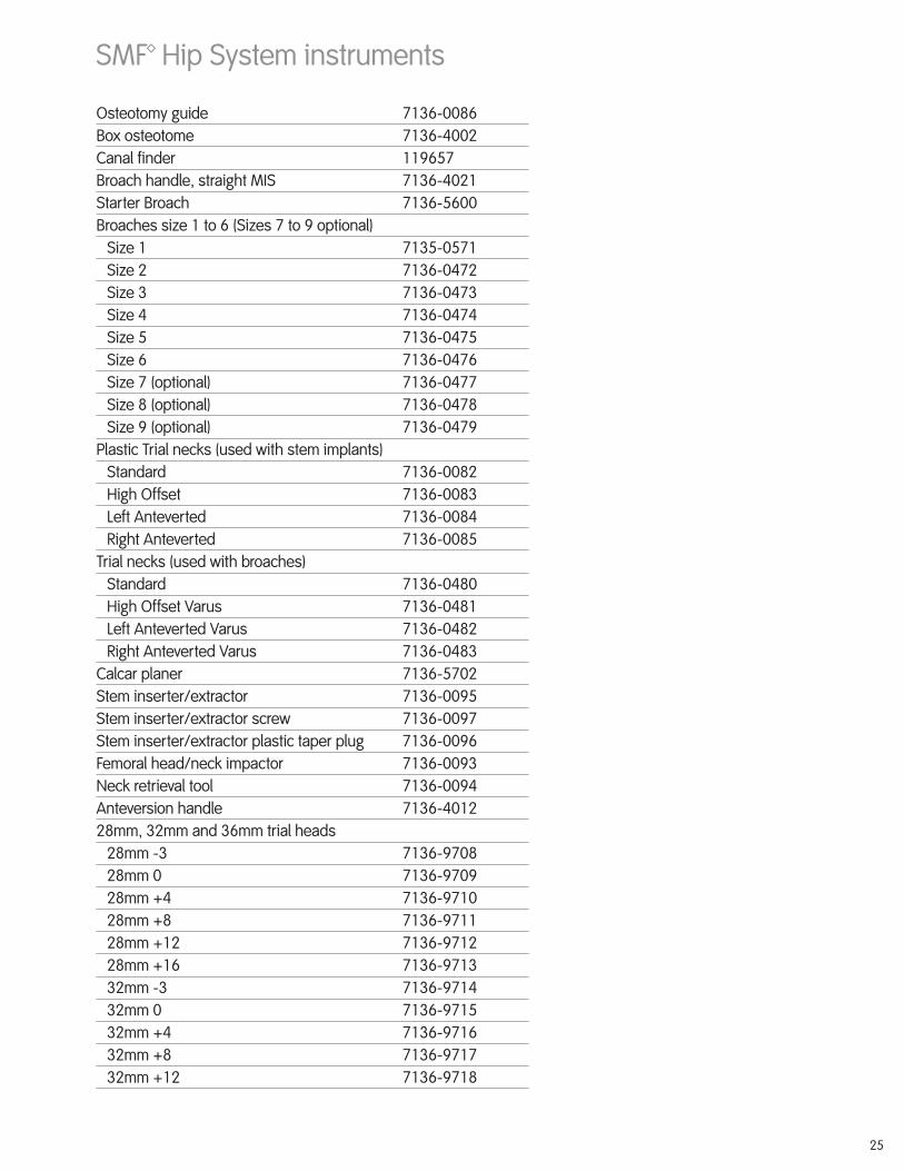
Osteotomy guide 7136-0086Box osteotome 7136-4002Canal finder 119657Broach handle, straight MIS 7136-4021Starter Broach 7136-5600Broaches size 1 to 6 (Sizes 7 to 9 optional)
Size 1 7135-0571 Size 2 7136-0472 Size 3 7136-0473 Size 4 7136-0474 Size 5 7136-0475 Size 6 7136-0476 Size 7 (optional) 7136-0477 Size 8 (optional) 7136-0478 Size 9 (optional) 7136-0479
Plastic Trial necks (used with stem implants)Standard 7136-0082High Offset 7136-0083Left Anteverted 7136-0084Right Anteverted 7136-0085
Trial necks (used with broaches)Standard 7136-0480High Offset Varus 7136-0481Left Anteverted Varus 7136-0482Right Anteverted Varus 7136-0483
Calcar planer 7136-5702Stem inserter/extractor 7136-0095Stem inserter/extractor screw 7136-0097Stem inserter/extractor plastic taper plug 7136-0096Femoral head/neck impactor 7136-0093Neck retrieval tool 7136-0094Anteversion handle 7136-401228mm, 32mm and 36mm trial heads
28mm -3 7136-970828mm 0 7136-970928mm +4 7136-971028mm +8 7136-971128mm +12 7136-971228mm +16 7136-971332mm -3 7136-971432mm 0 7136-971532mm +4 7136-971632mm +8 7136-971732mm +12 7136-9718
SMF™ Hip System instruments

26
32mm +16 7136-971936mm -3 7136-972036mm 0 7136-972136mm +4 7136-972236mm +8 7136-972336mm +12 7136-9724
Accessory Instruments (Included in R3 Cup and/or Reflection Cup Instrument Sets)
3.5mm Hex Screwdriver Shaft 7136-2293Ratcheting Handle 7136-2294T-handle 7136-4006
Optional InstrumentsLeft/right double offset broach handles
Left 7136-0089Right 7136-0090
Femoral Head Reducer 7136-3076Replacement Tip for Head Impactor 7136-0484
SMF™ Hip System instruments

27
Important Medical InformationWarnings and PrecautionsTotal Hip SystemImportant NoteTotal hip replacement (THR) arthroplasty has become a successful procedure for relieving pain and restoring motion in patients who are disabled from hip arthropathy. The goals of total hip replacement are to decrease pain, increase function, and increase mobility.
MaterialsFemoral components are cobalt chromium alloy, titanium 6Al-4V alloy or stainless steel. Femoral heads are cobalt chromium alloy, OXINIUM™ oxidized zirconium, BIOLOX®
forte alumina ceramic, BIOLOX delta alumina/zirconia ceramic or stainless steel. Acetabular liners are ultra-high molecular weight polyethylene (UHMWPE), cobalt chromium (CoCr) alloy, BIOLOX forte alumina ceramic, or BIOLOX delta alumina/zirconia ceramic. All poly acetabular components are UHMWPE. Acetabular shells are titanium 6Al-4V alloy or cobalt chromium (CoCr). The component material is provided on the outside carton label. Note: BIOLOX delta ceramic liners are not available in the US.
Some of the alloys needed to produce orthopedic implants contain some metallic components that may be carcinogenic in tissue cultures or intact organism under very unique circumstances. Questions have been raised in the scientific literature as to whether or not these alloys may be carcinogenic in implant recipients. Studies conducted to evaluate this issue have not identified conclusive evidence of such phenomenon, in spite of the millions of implants in use.
Description of SystemThe Total Hip System consists of femoral components, modular necks, proximal sleeves, taper sleeves, acetabular components, fixation screws and pegs, hole covers, centralizers, and femoral heads. Components may be grit blasted, porous coated, hydroxylapatite (HA) coated, or HA porous coated. All implantable devices are designed for single use only.
Femoral ComponentsFemoral components are available in a variety of sizes. Porous coated components are coated for biological ingrowth and are intended to be used without cement. Modular femoral components are available with an oval taper to accept Smith & Nephew, Inc. CoCr modular necks and/or a Morse type taper to accept proximal sleeves. Non-porous femoral components can feature PMMA centralizers that help produce a uniform thickness of cement.
Femoral components are available with a Small (10/12), Large (14/16), or 12/14 taper.
Small taper femoral components mate and lock directly with a 22 mm metal or oxidized zirconium or ceramic heads. The Small taper also mates with a taper sleeve which, in turn, mates with either metal or ceramic heads (26, 28, or 32 mm), bipolar or unipolar components.
Large taper femoral components mate and lock with either metal heads (26, 28, or 32 mm), ceramic heads (28 or 32 mm), oxidized zirconium (28, 32, or 36mm), bipolars or unipolar components.
Femoral components or modular necks with a 12/14 taper mate and lock with either metal heads, oxidized zirconium heads, ceramic heads, bipolar or unipolar components.
Small, Large, and 12/14 taper femoral component tapers are machined to mate and lock with ceramic heads, thus preventing rotation of the ceramic head on the stem, which would cause wear of the stem taper.
Taper SleevesA taper sleeve is required to be impacted on the Small taper femoral component prior to impacting a Large (14/16) taper femoral head size 26, 28, or 32 mm. A taper sleeve is required to attach a unipolar head. Unipolar taper sleeves are available in Small, Large, and 12/14 tapers. Never place more than one taper sleeve on a femoral component.
Modular NecksModular necks are available in a variety of configurations. The modular neck mates and locks with the oval taper of a modular femoral component on one end and the taper of a 12/14 femoral head on the other end.
Femoral HeadsCobalt chromium, stainless steel, oxidized zirconium, and ceramic heads are available in multiple neck lengths for proper anatomic and musculature fit. Heads are highly polished for reduced friction and wear.
The following BIOLOX forte ceramic heads and BIOLOX delta ceramic heads are available for use only with 12/14 taper femoral components:
BIOLOX forte Ceramic Heads
HeadDiameter
Neck Length
71332800 71330280* 526969 28mm S/+0
71332804 71330284* 526970 28mm M/+4
71332808 71330288* 526971 28mm L/+8
71333200 71330320** 526914 32mm S/+0
71333204 71330324** 526915 32mm M/+4
71333208 71330328** 526916 32mm L/+8
71331047 71332084*** 76539150 36mm S/+0
71331048 71332085*** 76539151 36mm M/+4
71331049 71332086*** 76539152 36mm L/+8
*Used with REFLECTION BIOLOX forte Ceramic Acetabular Liners in the US.**Used with REFLECTION BIOLOX forte Ceramic Acetabular Liners and R3 BIOLOX forte Ceramic Acetabular Liners in the US.***Used with R3 BIOLOX forte Ceramic Acetabular Liners in the US.
BIOLOX delta Ceramic Heads
Head Diameter Neck Length
71346001 28mm S/+0
71346002 28mm M/+4
71346003 28mm L/+8
76539160 32mm S/+0
76539161 32mm M/+4
76539162 32mm L/+8
76539165 36mm S/+0
76539166 36mm M/+4
76539167 36mm L/+8
76539153* 36mm XL/+12
71346004 40mm S/+0
71346005 40mm M/+4
71346006 40mm L/+8
71330029 44mm S/+0
71330031 44mm M/+4
71330032 44mm L/+8
*Not available in the US.
The following CoCr BIRMINGHAM HIP™ (BH) modular heads* should be used only with BIRMINGHAM HIP acetabular cups and R3 metal acetabular liners:
74222138 Modular Head 38mm
74222140 Modular Head 40mm
74222142 Modular Head 42mm
74222144 Modular Head 44mm
74222146 Modular Head 46mm
74222148 Modular Head 48mm
74222150 Modular Head 50mm
74222152 Modular Head 52mm
74222154 Modular Head 54mm
74222156 Modular Head 56mm
74222158 Modular Head 58mm
*BH Modular Heads are not available in the US.
Acetabular ComponentsAcetabular components can be one-piece all polyethylene, or two-piece, consisting of a titanium shell and either a UHMWPE liner, BIOLOX forte ceramic liner, BIOLOX delta ceramic liner or CoCr metal liner. For BIOLOX forte ceramic liners available for use with the REFLECTION™ Ceramic Acetabular System in the US, refer to the separate package insert provided with these components. See Warnings and Precautions for specific information on screws, pegs and hole covers use. Acetabular reinforcement and reconstruction rings are used with an all polyethylene acetabular component. Note: BIOLOX delta ceramic liners are not available in the US. For R3 metal liners available for use with the BIRMINGHAM HIP Resurfacing (BHR) System in the US, refer to the separate package insert provided with these components.
Note: 10 Mrad cross-linked UHMWPE acetabular liners may be used with metal (CoCr), oxidized zirconium, BIOLOX forte ceramic heads or BIOLOX delta ceramic heads.
Femoral components and femoral heads are designed for use with any Smith & Nephew polyethylene acetabular component or polyethylene-lined, metal-backed acetabular component having an appropriately-sized inside diameter. Acetabular liners are designed for use only with acetabular shells from the same product family (i.e. REFLECTION liners can only be used with REFLECTION shells; R3 liners can only be used with R3 shells).
Indications, contraindications and adverse effectsHip components are indicated for individuals undergoing primary and revision surgery where other treatments or devices have failed in rehabilitating hips damaged as a result of trauma or noninflammatory degenerative joint disease (NIDJD) or any of its composite diagnoses of osteoarthritis, avascular necrosis, traumatic arthritis, slipped capital epiphysis, fused hip, fracture of the pelvis, and diastrophic variant.
Hip components are also indicated for inflammatory degenerative joint disease including rheumatoid arthritis, arthritis secondary to a variety of diseases and anomalies, and congenital dysplasia; treatments of nonunion, femoral neck fracture and trochanteric fractures of the proximal femur with head involvement that are unmanageable using other techniques; endoprosthesis, femoral osteotomy, or Girdlestone resection; fracture-dislocation of the hip; and correction of deformity.
Total hip systems may be indicated for use with bone cement, without bone cement, or for use with or without cement.
The MDF revision hip system is intended to be used without cement . In the EU, MDF is indicated for revision surgery only.
Acetabular reinforcement and reconstruction rings are intended to be used in primary and revision surgeries where the acetabulum has the deficiencies of the acetabular roof, anterior or posterior pillar, medial wall deficiency, and / or protrusion as a result of the indications listed previously.
Some of the diagnoses listed above and below may also increase the chance of complications and reduce the chance of a satisfactory result.
Contraindications1. Conditions that would eliminate or tend to eliminate
adequate implant support or prevent the use of an appropriately- sized implant, e.g.:a. blood supply limitations;b. insufficient quantity or quality of bone support, e.g.,
osteoporosis, or metabolic disorders which may impair bone formation, and osteomalacia; and
c. infections or other conditions which lead to increased bone resorption.
2. Mental or neurological conditions which tend to impair the patient’s ability or willingness to restrict activities.
3. Physical conditions or activities which tend to place extreme loads on implants, e.g., Charcot joints, muscle deficiencies, multiple joint disabilities, etc.
4. Skeletal immaturity.5. The alumina ceramic liner is contraindicated for use with any
product other than the metal shell with the correlating inner taper geometry and the appropriate sized alumina ceramic head. The alumina ceramic liner should only be used with the alumina ceramic head.
Contraindications may be relative or absolute and must be carefully weighed against the patient’s entire evaluation and the prognosis for possible alternative procedures such as non-operative treatment, arthrodesis, femoral osteotomy, pelvic osteotomy, resection arthroplasty, hemiarthroplasty and others.
Conditions presenting increased risk of failure include: osteoporosis, metabolic disorders which may impair bone formation, and osteomalacia.
Possible Adverse Effects1. Wear of the polyethylene and ceramic articulating surfaces of
acetabular components may occur. Higher rates of wear may be initiated by the presence of particles of cement, metal, or other debris which can develop during or as a result of the surgical procedure and cause abrasion of the articulating surfaces. Higher rates of wear may shorten the useful life of the prosthesis and lead to early revision surgery to replace the worn prosthetic components.
2. With all joint replacements, asymptomatic, localized, progressive bone resorption (osteolysis) may occur around the prosthetic components as a consequence of foreign-body reaction to particulate wear debris. Particles are generated by interaction between components, as well as between the components and bone, primarily through wear mechanisms of adhesion, abrasion, and fatigue. Secondarily, particles may also be generated by third-body particles lodged in the polyethylene or ceramic articular surfaces. Osteolysis can lead to future complications necessitating the removal or replacement of prosthetic components.
3. Loosening, bending, cracking, or fracture of implant components may result from failure to observe the Warnings and Precautions below. Fracture of the implant can occur as a result of trauma, strenuous activity, improper alignment, or duration of service.
4. Dislocations, subluxation, decreased range of motion, or lengthening or shortening of the femur caused by improper neck selection, positioning, looseness of acetabular or femoral components, extraneous bone, penetration of the femoral prosthesis through the shaft of the femur, fracture of the acetabulum, intrapelvic protrusion of acetabular component, femoral impingement, periarticular calcification, and/or excessive reaming.
5. Fracture of the pelvis or femur: post-operative pelvic fractures are usually stress fractures. Femoral fractures are often caused by defects in the femoral cortex due to misdirected reaming, etc. Intraoperative fractures are usually associated with old congenital deformity, improper stem selection, improper broaching, and/or severe osteoporosis.
6. Infection, both acute post-operative wound infection and late deep wound sepsis.

28
7. Neuropathies; femoral, sciatic, peroneal nerve, and lateral femoral cutaneous neuropathies have been reported. Temporary or permanent nerve damage resulting in pain or numbness of the affected limb.
8. Wound hematoma, thromboembolic disease including venous thrombosis, pulmonary embolus, or myocardial infarction.
9. Myositis ossificans, especially in males with hypertrophic arthritis, limited preoperative range of motion and/or previous myositis. Also, periarticular calcification with or without impediment to joint mobility can cause decreased range of motion.
10. Trochanteric nonunion usually associated with early weight bearing and/or improper fixation of the trochanter, when a transtrochanteric surgical approach is used.
11. Although rare, metal sensitivity reactions and/or allergic reactions to foreign materials have been reported in patients following joint replacement.
12. Damage to blood vessels.13. Traumatic arthrosis of the knee from intraoperative
positioning of the extremity.14. Delayed wound healing.15. Aggravated problems of the affected limb or contralateral
extremity caused by leg length discrepancy, excess femoral medialization, or muscle deficiency.
16. Failure of the porous coating/ substrate interface or hydroxylapatite coating/ porous coating bonding may result in bead separation delamination.
17. Stem migration or subsidence has occurred in conjunction with compaction grafting procedures usually resulting from insufficient graft material or improper cement techniques. Varus stem alignment may also be responsible.
18. Stem loosening or fracture, particularly of smaller sized stems, is most likely to occur in patients who are young, physically active, and/or heavy.
19. Temporary or permanent device related noise such as clicking or squeaking.
Warnings and PrecautionsThe patient should be warned of surgical risks, and made aware of possible adverse effects. The patient should be warned that the device does not replace normal healthy bone, that the implant can break or become damaged as a result of activity or trauma, and that it has a finite expected service life and may need to be replaced in the future. Do not mix components from different manufacturers unless specially approved by the manufacturer of the components. For purposes of product inter-compatibility, products manufactured and labeled by entities formerly known as Plus Endoprothetik, Intraplant, Precision Implants and Plus Orthopedics (now Smith & Nephew Orthopaedics AG) may be considered as the same manufacturer, Smith & Nephew. Additional Warnings and Precautions may be included in component literature.
Preoperative1. Use extreme care in handling and storage of implant
components. Cutting, bending, or scratching the surface of components can significantly reduce the strength, fatigue resistance, and/or wear characteristics of the implant system. These, in turn, may induce internal stresses that are not obvious to the eye and may lead to fracture of the component. Implants and instruments should be protected from corrosive environments such as salt air during storage. Do not allow the porous surfaces to come in contact with cloth or other fiber-releasing materials.
2. Allergies and other reactions to device materials, although infrequent, should be considered, tested for (if appropriate), and ruled out preoperatively.
3. Fixation and expected longevity of components expected to be left in place at revision surgery should be thoroughly assessed.
4. Surgical technique information is available upon request. The surgeon should be familiar with the technique. Refer to medical or manufacturer literature for specific product information.
5. Intraoperative fracture or breaking of instruments can occur. Instruments which have experienced extensive use or excessive force are susceptible to fracture. Instruments should be examined for wear, or damage, prior to surgery. Single use devices should not be reused due to risks of breakage, failure or patient infection.
6. Do not cold water quench ceramic components and never sterilize ceramic heads while fixed on the stem taper. (See sterilization section, below.)
7. OXINIUM™ oxidized zirconium femoral heads and cobalt chrome femoral heads are designed to articulate with UHMWPE bearing surfaces. BIOLOX forte ceramic femoral heads and BIOLOX delta ceramic femoral heads articulate with UHMWPE liners or cups, BIOLOX forte ceramic liners or BIOLOX delta ceramic liners. OXINIUM oxidized zirconium femoral heads, cobalt chrome femoral heads, BIOLOX forte ceramic femoral heads and BIOLOX delta ceramic femoral heads should never articulate against metal because severe wear of the bearing surfaces may occur. BHR resurfacing heads and Birmingham Hip CoCr modular heads articulate with Birmingham Hip acetabular cups or R3 metal liners. Note: BIOLOX delta ceramic liners and Birmingham Hip CoCr modular heads are not available in the US.
8. Select only Smith & Nephew femoral components that indicate their use with ceramic heads. This is important because the taper on the stem is machined to tightly mate and lock with the ceramic head thus preventing rotation of the ceramic head on the stem. Also, an improperly dimensioned taper could result in fracture of the ceramic head.
9. Alumina ceramic should never articulate against metal because severe wear could occur.
10. The SL-PLUS™ Stems, SL-PLUS Lateralized Stems, SLR-PLUS™ Stems and SL-PLUS MIA Stems are compatible with Smith & Nephew ball heads, including Unipolar and Bipolar, with the exception of +16 offset all sizes. Do not use the Smith & Nephew +16 heads with SL-PLUS Stems and SLR-PLUS Stems.
11. If a computer assisted surgery system is used, consult the applicable software and hardware reference manuals provided by the manufacturer to ensure proper operation of this equipment.
Intraoperative1. The general principles of patient selection and sound
surgical judgment apply. The correct selection of the implant is extremely important. The appropriate type and size should be selected for patients with consideration of anatomical and biomechanical factors such as patient age and activity levels, weight, bone and muscle conditions, any prior surgery and anticipated future surgeries, etc. Generally, the largest cross-section component which will allow adequate bone support to be maintained is preferred. Failure to use the optimum-sized component may result in loosening, bending, cracking, or fracture of the component and/or bone.
2. Correct selection of the neck length and cup, and stem positioning, are important. Muscle looseness and/or malpositioning of components may result in loosening, subluxation, dislocation, and/or fracture of components. Increased neck length and varus positioning will increase stresses which must be borne by the stem. The component should be firmly seated with the component insertion instruments.
3. Care should be taken not to scratch, bend (with the exception of the Reconstruction Rings) or cut implant components during surgery for the reasons stated in Number One of the “Pre-Operative” section of “Warnings and Precautions.”
4. A +12 mm or +16 mm femoral head should not be used with any Small taper stems.
5. MATRIX™ Small taper stem sizes 8S - 10L must have a minimum neck length of +8 mm when used with a bipolar component; and Small taper stem sizes 12S - 16L must have a minimum neck length of +4 mm when used with a bipolar component.-
6. Modular heads, modular necks, modular sleeves and femoral components should be from the same manufacturer unless specially approved by the manufacturer of the components to prevent mismatch.
7. Stainless steel heads and stainless steel stems should only be used together. Neither should be used with other metal components.
8. Use only REFLECTION Liners with REFLECTION Shells. Use only R3 Liners with R3 Shells.
9. Clean and dry all taper connections prior to impacting for assembly. The modular femoral head, neck and/or sleeve components must be firmly seated on the femoral component to prevent disassociation.
10. Take care, when positioning and drilling screw and peg holes, to avoid penetration of the inner cortex of the pelvis, penetration of the sciatic notch, or damage to vital neurovascular structures. Perforation of the pelvis with screws that are too long can rupture blood vessels causing the patient to hemorrhage. Do not place a screw in the center hole of the acetabular prosthesis. Placement of drills and screws in the anterior or medial portions of the prosthesis is associated with a high risk of potentially fatal vascular injury. Bone screws must be completely seated in the holes of the shell to allow proper locking for the acetabular component liner. If the tapered pegs need to be removed from the shell after impaction of the pegs, do not reuse the pegs or the peg shell holes. Use new pegs and different shell holes, or a new shell if necessary.
11. REFLECTION Three Hole, FSO, INTERFIT™ and R3 Shells accept both REFLECTION spherical head screws and Universal cancellous bone screws. REFLECTION FSO and INTERFIT Shells accept the Modified REFLECTION screw hole covers. The REFLECTION V Shell only accepts Universal Cancellous, REFLECTION screws, tapered screw-hole covers and tapered, pegs. REFLECTION Peripheral Hole Screws should only be used with REFLECTION Peripheral Hole Shells. Locking Head Pegs and REFLECTION Locking Head Screw Hole Covers are only for use with REFLECTION Three Hole Shells. The threaded center hole in REFLECTION Shells only accepts threaded hole covers, not screws or pegs. The INTERFIT threaded hole cover is only for use with REFLECTION INTERFIT, Spiked and No Hole Shells. The REFLECTION threaded hole cover can be used with all REFLECTION and R3 shells. The R3 screw hole cover can be used with R3 and REFLECTION Three Hole shells. Refer to product literature for proper adjunctive fixation and hole cover usage.
12. Prior to seating modular components, surgical debris including tissue must be cleaned from the surfaces. Debris, including bone cement, may inhibit the component locking mechanism. If the shell is to be cemented in place, remove extraneous cement with a plastic sculps tool to ensure proper locking of the liner. During liner insertion, make sure soft tissue does not interfere with the shell/liner interface. Chilling the liner reduces the impaction force required to seat the liner. Modular components must be assembled securely to prevent disassociation. Debris inhibits the proper fit and locking of modular components which may lead to early failure of the procedure. Failure to properly seat the acetabular liner into the shell can lead to disassociation of the liner from the shell.
13. Avoid repeated assembly and disassembly of the modular components which could compromise the critical locking action of the locking mechanism.
14. Care is to be taken to assure complete support of all parts of the device embedded in bone cement to prevent stress concentration which may lead to failure of the procedure. During curing of the cement, care should be taken to prevent movement of the implant components.
15. If the head is removed from a femoral component that will be left in place at revision surgery, it is recommended that a metal head be used. A ceramic head may fracture from irregularities on the femoral component taper.
16. If components are to be left in place at revision surgery, they should first be thoroughly checked for signs of looseness, etc. and replaced if necessary. The head/neck component should be changed only when clinically necessary.
17. Once removed from the patient, implants previously implanted should never be reused, since internal stresses which are not visible may lead to early bending or fracture of these components. Reuse may also increase the risk of patient infection.
18. With the congenitally dislocated hip, special care should be taken to prevent sciatic nerve palsy. Also, note that the femoral canal is often very small and straight and may require an extra-small straight femoral prosthesis; however, a regular-sized prosthesis should be used when possible. Note that the true acetabulum is rudimentary and shallow. A false acetabulum should not ordinarily be utilized as a cup placement site for anatomical and biomechanical reasons.
19. With rheumatoid arthritis, especially for those patients on steroids, bone may be extremely osteoporotic. Care should be taken to prevent excessive penetration of the acetabular floor or fracture of the medial acetabular wall, femur, or greater trochanter.
20. Revision procedures for previous arthroplasty, Girdlestone, etc., are technically demanding and difficult to exercise. Common errors include misplacement of the incision, inadequate exposure or mobilization of the femur, inadequate removal of ectopic bone, or improper positioning of components. Postoperative instability as well as excessive blood loss can result. In summary, increased operative time, blood loss, increased incidence of pulmonary embolus and wound hematoma can be expected with revision procedures.
21. Prior to closure, the surgical site should be thoroughly cleaned of cement, bone chips, ectopic bone, etc. Ectopic bone and/or bone spurs may lead to dislocation or painful or restricted motion. Range of motion should be thoroughly checked for early contact or instability.
22. Proper positioning of the components is important to minimize impingement which could lead to early failure, premature wear, and/or dislocation.
23. In order to minimize the risks of dislocation and loosening of the shell-acetabular bone or shell-bone cement interface that may occur when using a metallic shell intended for biological fixation or cemented use only, surgeons should consider providing immediate resistance to tensile forces between the metallic shell and the acetabular bone or bone cement interface through the use of orthopedic bone fixation devices such as bone screws, spikes, screw threads, pegs, fins, or other bone fixation devices.
24. Physicians should consider component malposition, component placement, and the effect on range of motion when using modular heads (with sleeves or skirts) and extended liners.
25. For computer assisted surgery systems, it is extremely important to correctly select input parameters (e.g. bony landmarks). Operators of this equipment should be familiar with the anatomy relevant to the procedure. Failure to provide proper input could cause problems such as violation of critical anatomical structures and malpositioned implants.
26. Do not implant HA-coated devices in bone cement.
Postoperative1. Postoperative directions and warnings to patients by
physicians, and patient care, are extremely important. Gradual weight bearing is begun after surgery in ordinary total hip arthroplasty. However, with trochanter osteotomy or certain complex cases, weight-bearing status should be individualized with the non or partial weight-bearing period extended.
2. Patients should be warned against unassisted activity, particularly use of toilet facilities and other activities requiring excessive motion of the hip.
3. Use extreme care in patient handling. Support should be provided to the operative leg when moving the patient. While placing the patient on bedpans, changing dressings, and clothing, and similar activities, precautions should be taken to avoid placing excessive load on the operative part of the body.
4. Postoperative therapy should be structured to regain muscle strength around the hip and a gradual increase of activities.
5. Periodic X-Rays are recommended for close comparison with immediate postoperative conditions to detect long-term evidence of changes in position, loosening, bending and/or cracking of components or bone loss. With evidence of these conditions, patients should be closely observed, the possibilities of further deterioration evaluated, and the benefits of early revision considered.
6. Prophylactic antibiotics should be recommended to the patient similar to those suggested by the American Heart Association for conditions or situations that may result in bacteremia.
7. Normal daily activity may be resumed at the physician’s direction. Patients should be directed to seek medical opinion before entering potentially adverse environments that could affect the performance of the implant, such as electromagnetic or magnetic fields, including a magnetic resonance environment.
Magnetic Resonance Imaging (MRI) SafetySmith & Nephew hip systems have not been evaluated for safety and compatibility in the MR environment. Hip system components have not been tested for heating or migration in the MR environment.
Packaging and Labeling Implants should only be accepted if received by the hospital or surgeon with the factory packaging and labeling intact. If the sterile barrier has been broken, return the component to Smith & Nephew, Inc.
SterilizationImplant components are supplied sterile to a Sterility Assurance Level (SAL) of 10-6. Implant components are supplied in protective packaging. Inspect packages for punctures or other damage prior to surgery. The method of sterilization is noted on the package label.
DO NOT REUSE OR RESTERILIZE implant components or single use disposable instruments. Contact your local Smith & Nephew, Inc. Sales Representative regarding procedures to return components. If not specifically labeled sterile, instruments are supplied non-sterile and must be cleaned and sterilized prior to surgery. Please see also the document, “Recommendations for decontamination and sterilization of Smith & Nephew orthopaedic devices”, which is provided with Smith & Nephew instrument sets, for further information on cleaning instructions and validated sterilization procedures.
Recommended Steam Sterilization Cycle Parameters• Dynamic Air Removal (Prevacuum) Steam Cycle: 132°C
(270°F) for 4 minutes or 135°C (275°F) for 3 minutes and a minimum vacuum drying time of 30 minutes.
• Gravity Displacement Steam Cycle: 132°C (270°F) for 30 minutes and a minimum vacuum drying time of 30 minutes.
• Flash Steam Cycle (Reusable instruments only): 132°C (270°F) for 10 minutes in a Gravity Displacement Cycle or 4 minutes in a Dynamic Air Removal (Prevacuum) Cycle.
• United Kingdom Steam Cycle: 134° C (273°F) for 3 minutes and a minimum vacuum drying time of 30 minutes. (Note: Sterilization evacuation and pulsing should be carried out in accordance with HTM 2010).

29
Containment devices should be wrapped with a central supply wrap (CSR) or placed in a reusable rigid container for sterilization. Note to US Customers: FDA cleared sterilizers and wraps are to be used in your sterilization processes.
Retrieval and Analysis of Removed ImplantsThe most important part of surgical implant retrieval is preventing damage that would render scientific examination useless. Special care should be given to protect the implant from damage during handling and shipment. Follow internal hospital procedures for the retrieval and analysis of implants removed during surgery. When handling removed implants, use precautions to prevent spread of bloodborne pathogens.
If the implant will be returned to Smith & Nephew, Inc. for analysis, contact Customer Service using the phone numbers outlined in the Information section.
INFORMATIONFor further information, please contact Customer Service at (800) 238-7538 for calls within the continental USA and (901) 396-2121 for all international calls.
Manufacturing facilities and EC representative: Smith & Nephew Inc.1450 Brooks RoadMemphis, TN 38116 U.S.A.Tel.: 901-396-2121
Smith & Nephew Orthopaedics GmbHAlemannenstrasse 1478532 Tuttlingen, GermanyTel.: 07462/208-0Fax: 07462/208-135
Caution: Federal Law (USA) restricts this device to sale by or on the order of a physician.
H2O2 – hydrogen peroxide sterilization
– For cemented use only
– For uncemented use only
™Trademark of Smith & Nephew. Certain Marks Reg. U.S. Pat. & TM Off. All trademarks acknowledged.
81073299 Rev. 0 2010-05

30
Notes

31

32
OrthopaedicsSmith & Nephew, Inc.7135 Goodlett Farms ParkwayCordova, TN 38016USA
Telephone: 1-901-396-2121Information: 1-800-821-5700Orders and Inquiries: 1-800-238-7538
™ Trademark of Smith & Nephew. Certain marks Reg. US Pat. & TM Off.
www.smith-nephew.com
©2011 Smith & Nephew, Inc.All rights reserved.7138-1476 REV0 01/11