SME2713 Metal Forming - 5 · Manufacturing Process METAL FORMING – 5 (Rod, wire and tube drawing...
15
8/20/2008 1 SME 2713 Manufacturing Process METAL FORMING – 5 (Rod, wire and tube drawing processes) Assoc Prof Zainal Abidin Ahmad UTM, Skudai Outline 1. Introduction 2 Rod and wire drawing 2. Rod and wire drawing 3. Defects in rod and wire drawing 4. Tube drawing 1. Sinking 2. Plug drawing 3 Mandrel drawing 3. Mandrel drawing 5. Lubrication 6. Defects in cold drawn products 20 August 2008 Assoc Prof Zainal Abidin Ahmad 2
Transcript of SME2713 Metal Forming - 5 · Manufacturing Process METAL FORMING – 5 (Rod, wire and tube drawing...

8/20/2008
1
SME 2713 Manufacturing Process
METAL FORMING – 5 (Rod, wire and tube drawing processes)
Assoc Prof Zainal Abidin Ahmad
UTM, Skudai
O u t l i n e
1. Introduction
2 Rod and wire drawing2. Rod and wire drawing
3. Defects in rod and wire drawing
4. Tube drawing1. Sinking
2. Plug drawing
3 Mandrel drawing3. Mandrel drawing
5. Lubrication
6. Defects in cold drawn products
20 August 2008 Assoc Prof Zainal Abidin Ahmad 2

8/20/2008
2
Introduction
• Drawing operations involve pulling metal through a die by means of a tensile force applied to the exit side of the die
Th l ti fl i d b i f i i f• The plastic flow is caused by compression force, arising from the reaction of the metal with the die
• Starting materials – hot rolled stocks (ferrous) and extruded (non‐ferrous)
• Material should have high ductility and good tensile strength
• Bar, wire and tube drawings are usually carried out at room temperature, except for large deformation, which leads to considerable rise in temperature during drawing
• The metal usually has a circular symmetry (but not always, depending on requirements)
20 August 2008 Assoc Prof Zainal Abidin Ahmad 3
Process Variables in Wire Drawing
Process variables in wire drawing. The die angle, the reduction in cross-sectional area per pass, the speed of drawing, the temperature, and the lubrication all affect
the drawing force, F.20 August 2008 Assoc Prof Zainal Abidin Ahmad 4

8/20/2008
3
Rod and wire drawing• Reducing the diameter through plastic deformation while the
volume remains the same
• Same principles for drawing bars, rods and wire but equipment is different in sizes depending on products
20 August 2008 Assoc Prof Zainal Abidin Ahmad 5
Wire drawing
• Wire drawing involves reducing the diameter of a rod or wire by passing through a series of drawing dies or platesdies or plates
20 August 2008 Assoc Prof Zainal Abidin Ahmad 6
8/20/2008
4
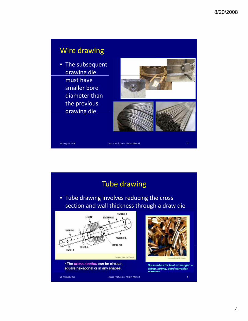
Wire drawing
• The subsequent drawing die must have smaller bore diameter than the previous drawing diedrawing die
20 August 2008 Assoc Prof Zainal Abidin Ahmad 7
Tube drawing
• Tube drawing involves reducing the cross section and wall thickness through a draw die
20 August 2008 Assoc Prof Zainal Abidin Ahmad 8

8/20/2008
5
Rod drawing
• Rods which can not coiled, are produced on d b hdrawbenches
• Rod is swaged, inserted through the die and clamped to the jaws of the drawhead. The d h d i d bdrawhead is moved by a hydraulic mechanism
20 August 2008 Assoc Prof Zainal Abidin Ahmad 9
Cold Drawing
Cold drawing of an extruded channel on a draw bench, to reduce its cross-section. Individual lengths of straight rod or of cross-sections are
drawn by this method. Source: Courtesy of The Babcock and Wilcox Company, Tubular Products Division.
20 August 2008 Assoc Prof Zainal Abidin Ahmad 10

8/20/2008
6
Wire drawing die• Shape of the bell causes hydrostatic pressure to increase and promotes the flow of lubricant into the die
• The approach angle – where the actual reduction iin diameter occurs, giving the half die angle, α
• The bearing region produces a frictional drag on the wire and also remove surface damage due to die wear, without changing dimensions
• The back relief allows the metal toThe back relief allows the metal to expand slightly as the wire leaves the die and also minimises abrasion if the drawing stos or the die is out of alignment
20 August 2008 Assoc Prof Zainal Abidin Ahmad 11
Example of wire drawing dies
20 August 2008 Assoc Prof Zainal Abidin Ahmad 12

8/20/2008
7
Example of wire drawing dies
20 August 2008 Assoc Prof Zainal Abidin Ahmad 13
Drawing die materials• Most drawing dies are cemented carbide or industrial diamond (for fine wires)
• Cemented carbide is composed of carbides of Ti, W, Ni, Mo, Ta, Hf
20 August 2008 Assoc Prof Zainal Abidin Ahmad 14

8/20/2008
8
Drawing die materials
• Cemented carbides are the most widely used for drawing d d hdies due to their superior strength, toughness, and wear resistance
• Polycrystalline diamond (PCD) used for wire drawing di f fi i Ldies – for fine wires. Longer die life, high resistance to wear, cracking or bearing
20 August 2008 Assoc Prof Zainal Abidin Ahmad 15
Wire drawing equipment• The wire is first passed through the overhead loop and pulley,
brought down and then inserted through the die of the second drum and drawn through this die for further reduction
20 August 2008 Assoc Prof Zainal Abidin Ahmad 16

8/20/2008
9
Wire drawing equipment
• Thus, the wire is drawn through all the wire drawing drums of the set in a continuous manner to get the required finishedthe set in a continuous manner to get the required finished diameter of the wire. Speed of each draw block has to be synchronised to avoid slippage between the wire and the block.
• The drawing speed – up to 10 m/sec for ferrous and up to 30 m/sec for nonferrous drawing
20 August 2008 Assoc Prof Zainal Abidin Ahmad 17
Wire drawing process
20 August 2008 Assoc Prof Zainal Abidin Ahmad 18

8/20/2008
10
Wire drawing process
• Bull block drawing allows the generation of long lengths
• Are reduction per drawing pass is rarely greater than
Top view Side view30 – 35%
20 August 2008 Assoc Prof Zainal Abidin Ahmad
Top view Side view
19
20 August 2008 Assoc Prof Zainal Abidin Ahmad 20
8/20/2008
11
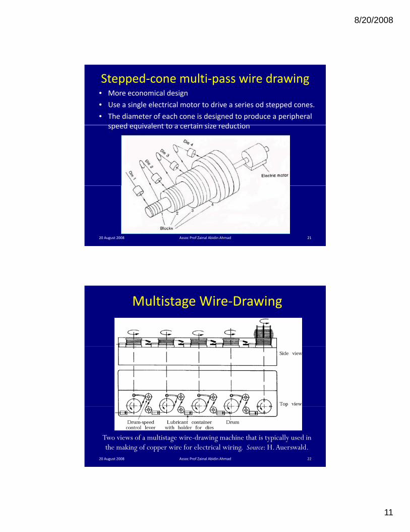
Stepped‐cone multi‐pass wire drawing• More economical design
• Use a single electrical motor to drive a series od stepped cones.
• The diameter of each cone is designed to produce a peripheral speed equivalent to a certain size reductionspeed equivalent to a certain size reduction
20 August 2008 Assoc Prof Zainal Abidin Ahmad 21
Multistage Wire‐Drawing
Two views of a multistage wire-drawing machine that is typically used in the making of copper wire for electrical wiring. Source: H. Auerswald.
20 August 2008 Assoc Prof Zainal Abidin Ahmad 22

8/20/2008
12
4. Tube drawing processes
• Following the hot forming process, tubes are cold drawn using dies, plugs or mandrels to the required shape sizemandrels to the required shape, size, tolerances and mechanical strength
• Provide good surface finishes
• Increase mechanical properties by strain hardening
• Can produce tubes with thinner walls or ll d h b b dsmaller diameters than can be obtained
from other hot forming methods
• Can produce more irregular shapes
20 August 2008 Assoc Prof Zainal Abidin Ahmad 23
20 August 2008 Assoc Prof Zainal Abidin Ahmad 24
8/20/2008
13
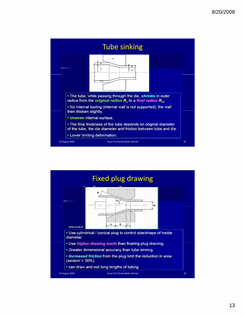
Tube sinking
20 August 2008 Assoc Prof Zainal Abidin Ahmad 25
Fixed plug drawing
20 August 2008 Assoc Prof Zainal Abidin Ahmad 26

8/20/2008
14
Floating plug drawing
20 August 2008 Assoc Prof Zainal Abidin Ahmad 27
Moving mandrel drawing
20 August 2008 Assoc Prof Zainal Abidin Ahmad 28

8/20/2008
15
Proper lubrication is essential in drawing, in order to improve die life, reduce drawing forces and temperature, and improve surface finish.
5. Lubrication
Types of Lubricationa) Wet drawing : Dies and Rods are completely immersed in
lubricantb) Dry drawing : Surface of the rod to be drawn is coated
with a lubricantc) Coating : Rod or Wire is coated with a soft metal that acts
as a solid lubricantd) Ultrasonic Vibration of the dies and mandrels.
20 August 2008 Assoc Prof Zainal Abidin Ahmad 29
6. Defects in cold drawn products
• Longitudinal scratches ‐ scored die, poor lubrication, or abrasive particles
• Slivers ‐ swarf drawn into the surface
• Long fissures – originating from ingot
• Internal cracks – pre‐existing defects in starting material or ruptures in the centre due to overdrawing
• Corrosion induced cracking – due to internal residual stresses
20 August 2008 Assoc Prof Zainal Abidin Ahmad 30