SMD · Technical Guidance Notes GUIDANCE NOTES 1.0 Product certification In accordance with legal...
72
SMD Structural Floor and Roof Solutions Technical Guidance Notes SMD.TGN.122.V8.1 TGNManual
Transcript of SMD · Technical Guidance Notes GUIDANCE NOTES 1.0 Product certification In accordance with legal...

SMDStructural Floor and Roof Solutions
Technical Guidance NotesSMD.TGN.122.V8.1
TGNManual

GU
IDAN
CE
NO
TES
Technical Guidance Notes
04 - Introduction
05 1.0 Productcertification
05 2.0 Specification05 2.1 Fall arrest systems05 2.2 Floordeckmaterialspecification05 2.3 Stud welding06 2.4 Roofdeckmaterialspecification06 2.5 Concrete
07 3.0 Health and Safety07 3.1 Management & supervision07 3.2 Documentation08 3.3 Personal Protective Equipment (PPE)08 3.4 Protection of falls from height08 3.5 Trained and competent workforce08 3.6 DO's for associated trades
09 4.0 Design - Floor deck09 4.1 Benefitsofcompositemetaldeck10 4.2 Sheet lengths10 4.3 Temporary propping11 4.4 Lateral restraint and diaphragm action12 4.5 Bearings / Support13 4.6 Fixings14 4.7 Cantilevers15 4.8 Edge trim16 4.9 Flashings17 4.10 Steps in slab17 4.11 End caps
18 5.0 Design - Floor deck Composite stage18 5.1 Reinforcement19 5.2 Saw cuts19 5.3 Fire20 5.4 Moving concentrated loads21 5.5 Long single span propped composite Slabs22 5.6 Forming service holes
25 6.0 Design - Floor deck Composite beam design25 6.1 Shear stud LAW (length after weld)25 6.2 Design rules for minimum degree of connection25 6.3 Shear stud reduction factors25 6.4 BS EN 1994-1-1 Reduction factors for SMD Products26 6.5 BS5950-3 Section 3.1 Reduction factors for SMD Products26 6.6 Shear stud spacing27 6.7 Transverse reinforcement for composite beams27 6.8 Alternative Shear Connectors
29 7.0 Design - Floor deck Considerations29 7.1 Falls and ramps29 7.2 Fixing tool and stud welding gun Restrictions30 7.3 Concrete encased beams30 7.4 Durability31 7.5 Aggressive environments32 7.6 Vibration32 7.7 Acoustics32 7.8 Thermal mass
34 8.0 Design - Roof deck34 8.1 Quality35 8.2 Spans35 8.3 Loads35 8.4 Standard end laps35 8.5 Extended end laps36 8.6 Raking supports and cutting36 8.7 Cantilevers36 8.8 Sheet lengths36 8.9 Fire rating36 8.10 Durability36 8.11 Acoustics37 8.12 Airtightness37 8.13 Fixingspecification40 8.14 Non-fragility40 8.15 Diaphragm design41 8.16 Protex® warranted insulated system41 8.17 Aesthetics41 8.18 Forming openings
Page Section Title
ContentsPage Section Title
2

GU
IDAN
CE
NO
TES
43 9.0 Supply of materials43 9.1 Delivery and access43 9.2 Pack size and sheet length limits44 9.3 Offloading,hoistingandstorage44 9.4 Pack labels / loading-out locations
46 10.0 Installation - Fall arrest systems46 10.1 Safety nets
49 11.0 Installation - Floor deck and shear studs50 11.1 Cartridge tools50 11.2 Decking around columns50 11.3 Unpaintedtopflanges50 11.4 Mobile stud welding equipment50 11.5 Static generator or mains supply50 11.6 Testing52 11.7 Scorching of beams52 11.8 Minimising grout loss
53 12.0 Concrete53 12.1 Site considerations54 12.2 Temporary propping54 12.3 Cleaning the decking54 12.4 Damaged decking54 12.5 Construction joints55 12.6 Reinforcement drawings and bending schedules55 12.7 Concrete mix requirements55 12.8 Placement56 12.9 Surfacefinish57 12.10 Surfaceflatness58 12.11 Curing58 12.12 Post-installation characteristics
Page Section Title
61 13.0 Product options61 13.1 HighDurabilityfloordeck62 13.2 Crushed ends deck sheets62 13.3 VoidSafe™ Protection System63 13.4 Perimeter toeboard64 13.5 Channel edge trim64 13.6 TAB-Deck™ – Fibre concrete64 13.7 Off-sitecutting66 13.8 Servicefixings
68 14.0 References 68 14.1 SMD documentation68 14.2 Industry best practice68 14.3 Design standards69 14.4 Further reading
Page Section Title
Changes and updates Updated added to TGN OnlineVersion 8.1• Section 8.1 Table 8.1a updated Yes• Section 9.2 Table 9.2a and 9.2b updated Yes
Version 8• Section 5.6 Table 5.6c added Yes• Section 8.18 New section added Yes• Section 9.3 Paragraph & Fig 9.3a & 9.3b added Yes
Version 7• Section 5.4.2 Sub-section added Yes
Version 6• Section 8.4 References update Yes• Section 8.15 References update Yes
3SMD.TGN.122.V8Technical Department
GU
IDAN
CE
NO
TES
Technical Guidance Notes
Need Further Guidance? Contact us on +44 (0)1202 718 898 or email our Technical Team on [email protected]
Visit www.smdltd.co.uk to access all the information in this document on our wiki page
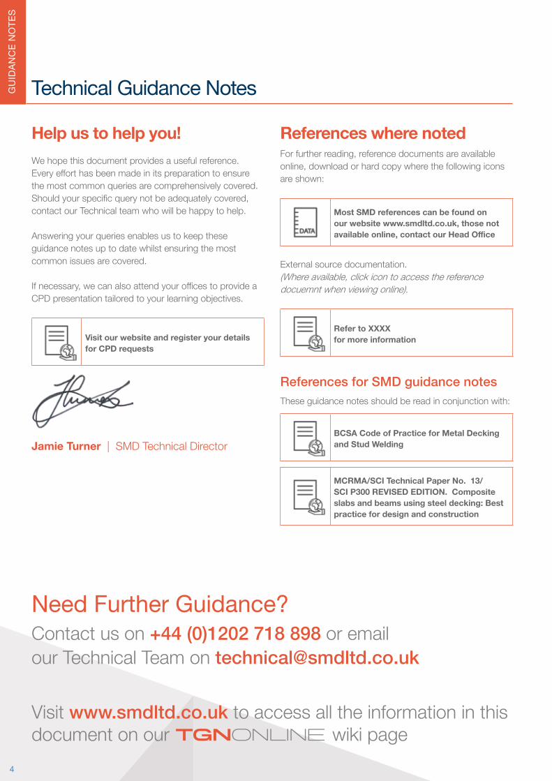
References where noted Forfurtherreading,referencedocumentsareavailableonline,downloadorhardcopywherethefollowingiconsare shown:
Most SMD references can be found on our website www.smdltd.co.uk, those not available online, contact our Head Office
External source documentation.(Whereavailable,clickicontoaccessthereferencedocuemnt when viewing online).
Refer to XXXXfor more information
References for SMD guidance notes These guidance notes should be read in conjunction with:
BCSA Code of Practice for Metal Decking and Stud Welding
MCRMA/SCI Technical Paper No. 13/SCI P300 REVISED EDITION. Composite slabs and beams using steel decking: Best practice for design and construction
Help us to help you!We hope this document provides a useful reference. Everyefforthasbeenmadeinitspreparationtoensurethe most common queries are comprehensively covered. Shouldyourspecificquerynotbeadequatelycovered,contact our Technical team who will be happy to help.
Answering your queries enables us to keep these guidance notes up to date whilst ensuring the most common issues are covered.
Ifnecessary,wecanalsoattendyourofficestoprovideaCPD presentation tailored to your learning objectives.
Visit our website and register your details for CPD requests
Jamie Turner | SMD Technical Director
4
TGNOnline
GU
IDAN
CE
NO
TES
Technical Guidance Notes
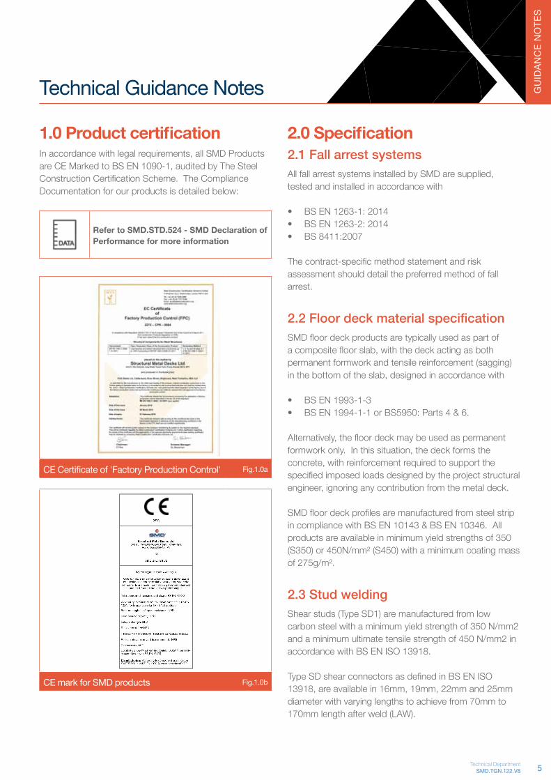
1.0 Product certification Inaccordancewithlegalrequirements,allSMDProductsareCEMarkedtoBSEN1090-1,auditedbyTheSteelConstructionCertificationScheme.TheComplianceDocumentation for our products is detailed below:
Refer to SMD.STD.524 - SMD Declaration of Performance for more information
CECertificateof'FactoryProductionControl' Fig.1.0a
CE mark for SMD products Fig.1.0b
2.0 Specification2.1 Fall arrest systemsAllfallarrestsystemsinstalledbySMDaresupplied,tested and installed in accordance with
• BS EN 1263-1: 2014• BS EN 1263-2: 2014 • BS 8411:2007
Thecontract-specificmethodstatementandriskassessment should detail the preferred method of fall arrest.
2.2 Floor deck material specificationSMDfloordeckproductsaretypicallyusedaspartofacompositefloorslab,withthedeckactingasbothpermanent formwork and tensile reinforcement (sagging) inthebottomoftheslab,designedinaccordancewith
• BS EN 1993-1-3 • BS EN 1994-1-1 or BS5950: Parts 4 & 6.
Alternatively,thefloordeckmaybeusedaspermanentformworkonly.Inthissituation,thedeckformstheconcrete,withreinforcementrequiredtosupportthespecifiedimposedloadsdesignedbytheprojectstructuralengineer,ignoringanycontributionfromthemetaldeck.
SMDfloordeckprofilesaremanufacturedfromsteelstripin compliance with BS EN 10143 & BS EN 10346. All products are available in minimum yield strengths of 350 (S350) or 450N/mm² (S450) with a minimum coating mass of 275g/m².
2.3 Stud weldingShear studs (Type SD1) are manufactured from low carbon steel with a minimum yield strength of 350 N/mm2 and a minimum ultimate tensile strength of 450 N/mm2 in accordance with BS EN ISO 13918.
TypeSDshearconnectorsasdefinedinBSENISO13918,areavailablein16mm,19mm,22mmand25mmdiameter with varying lengths to achieve from 70mm to 170mm length after weld (LAW).
5SMD.TGN.122.V8Technical Department
GU
IDAN
CE
NO
TES
Typical situations where welded shear studs are used include:
1. Thru-deck Stud Welding (on site) for Composite Beams
2. Stud Welding at Works for Composite Beams3. Plunge Columns4. Steel Piling5. Bridge Construction/Refurbishment6. Refractory Lining and Insulation Connectors7. Wear Resistant Studs
The most common use of welded shear studs (Type SD1) isintheconstructionofCompositeBeams,referSection7. For the use of welded shear studs in other situations contact the SMD Operations Team.
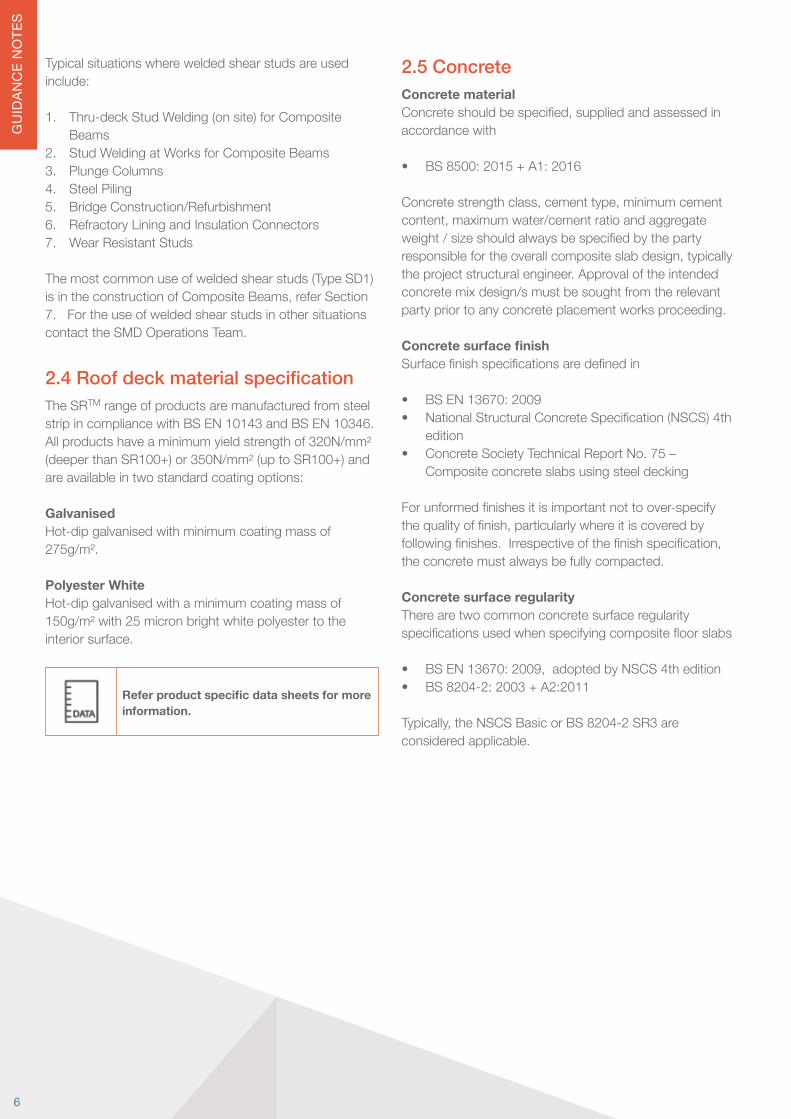
2.4 Roof deck material specificationThe SRTM range of products are manufactured from steel strip in compliance with BS EN 10143 and BS EN 10346. All products have a minimum yield strength of 320N/mm² (deeper than SR100+) or 350N/mm² (up to SR100+) and are available in two standard coating options:
Galvanised Hot-dip galvanised with minimum coating mass of 275g/m².
Polyester WhiteHot-dip galvanised with a minimum coating mass of 150g/m² with 25 micron bright white polyester to the interior surface.
Refer product specific data sheets for more information.
2.5 ConcreteConcrete materialConcreteshouldbespecified,suppliedandassessedinaccordance with • BS 8500: 2015 + A1: 2016 Concretestrengthclass,cementtype,minimumcementcontent,maximumwater/cementratioandaggregateweight/sizeshouldalwaysbespecifiedbythepartyresponsiblefortheoverallcompositeslabdesign,typicallythe project structural engineer. Approval of the intended concrete mix design/s must be sought from the relevant party prior to any concrete placement works proceeding. Concrete surface finishSurfacefinishspecificationsaredefinedin • BS EN 13670: 2009• NationalStructuralConcreteSpecification(NSCS)4th
edition• Concrete Society Technical Report No. 75 –
Composite concrete slabs using steel decking Forunformedfinishesitisimportantnottoover-specifythequalityoffinish,particularlywhereitiscoveredbyfollowingfinishes.Irrespectiveofthefinishspecification,the concrete must always be fully compacted. Concrete surface regularityThere are two common concrete surface regularity specificationsusedwhenspecifyingcompositefloorslabs • BSEN13670:2009,adoptedbyNSCS4thedition• BS 8204-2: 2003 + A2:2011 Typically,theNSCSBasicorBS8204-2SR3areconsidered applicable.
6

GU
IDAN
CE
NO
TES
Technical Guidance Notes
the ever-changing construction environment. Records of inductions and all toolbox talks should be maintained.Typical hazards associated with metal decking and associated preventative measures are:
Falls from Height Handrails,safetynets,temporarycovertovoidsandsuitable access to level
Hot Works Exclusionzones,removalofflammablematerials,fireblankets,firewatchandfireextinguishers
Use of Cartridge Tools Competency,trainingandPPE
Hand Arm Vibration Management procedures to reduce trigger times
Noise PPE,managementprocedures,suitableworkequipmentandoff-sitecutting
Cuts to Hands Training and PPE
Electrical Equipment Maintenance and use of 110v tools
Falling Materials from Height Trim / tool tethers and loading out in accordance with best practice
Removal of Waste Skipstolevel,loadingbaysetc.
Adverse Weather Management control
Slips, trips and fallsTraining,managementcontrol,PPEandhousekeepingmeasures
Manual Handling Designconsideration,loadingouttodrawingandoperative training
Refer to SMD Risk Assessments for more information
3.0 Health and SafetyThedesign,detailingandinstallationofSMDprojectsmust be planned and carried out ensuring the Health & Safetyofoperativesundertakingthework,othertradesonsite,andmembersofthegeneralpublic.
3.1 Management & supervisionEnsure supervision is experienced in metal decking and thatasuitablequalificationsuchasSMSTSisheld.Pre-start meetings should be arranged to enable agreement ofprogramme,sequence,attendancesandco-ordinationwith other trades. The planning and arrangement of deliveriestoalloweffectivepositioningofdeckpacksontothe steel frame (usually by the erectors) is essential in minimising issues with manual handling.
Refer to 'SIG.03 - Loading out and Positioning data sheet' at www.smdltd.co.uk
RobustmanagementoftheworkforceinrelationtoSafety,QualityandProductionensuressafeandefficientdelivery.Handover procedures shall be used to ensure works are complete prior to access being given to following trades.
3.2 DocumentationAll companies should have a framework of Policies and Procedures relating to the management of Health & Safety.SMDhavedevelopedaspecificSiteInstallationGuidetoassistoperativeswithtrade-specificguidancenotes.
Refer to SMD.SDC.210 - Site Installation Guide for more information
Contract-specificsafetydocumentation,includingMethodStatements,RiskAssessmentsandCOSHHdatasheetsare available for all hazards / activities associated with thehandlingandfixingofmetaldeckingandassociatedaccessories.Thecommunicationofthistotheworkforce,ensures that all operatives understand the risks and preventative measures that have been agreed. An initial toolboxtalkonthemethodstatement,followedbyfurtherweekly talks ensures procedures on site are appropriate to
7SMD.TGN.122.V8Technical Department

GU
IDAN
CE
NO
TES
3.3 Personal Protective Equipment (PPE)Task-specificPPEwillbedetailedintheProjectRiskAssessments,howevertheminimumrequirementsare:
• Hard Hat to BS EN 397• Safety Boots with heavy duty
steel toecap and steel mid-sole• Hi-Vis clothing to BS EN 471
Class 1• Cut Resistant Gloves to BS EN
388 – Cut 1 and Cut 5 rated• Ear protection to BS EN 352-1• Tinted Welding Goggles• Eye Protection to BS EN 166
class 1 – clear lenses for cutting/shot-firing,smokedlensesforstud welding
Site PPE - Minimum requirements Fig.3.3a
3.4 Protection of falls from heightIn accordance with the Work at Height Regulations 2005 and given that for deck installation ‘avoid work at height’ and ‘use work equipment to prevent falls’ is notreasonablypracticable,allcontractsneedtoadopta system of work that ‘minimises the distance and consequence of a fall’. Typical methods of fall arrest used aresafetynettingforsteelframestructuresor,airbagsorsimilar for other support situations. Where safety netting isprovidedbySMD,thiswillbeundertakenbyFASET(FallArrest Safety Equipment Training trade association and trainingbody)trainedpersonnel.Thecontract-specificmethod statement and risk assessment will detail the preferred methods for both fall arrest and installation.
Passive collective fall protection should always be selectedoverpersonalprotection,suchasharnessesandrunning lines.
3.5 Trained and competent workforceEnsure that all operatives have received manufacturers training in the use of cartridge tools and general training forabrasivewheels,manualhandling,safeuseofPPE,workingatheight,studweldingequipmentandfiresafetytraining. They must also have achieved the appropriate levelofCSCSqualification.SafetynetoperativesmustbeFASETtrainedandholdIPAFcertificatesforusingMobileElevated Working Platforms (MEWP's).
SMD have a dedicated training manager and detailed
training matrix of all operatives ensuring all site personnel arekeptup-to-datewiththelatestHealth,SafetyandCompetency training requirements.
3.6 DO's for associated tradesLand packs on the frame in the correct position It is essential that the decking packs are loaded out in the position indicated on SMD’s decking layout drawings to minimise the manual handling risk!
Fix all sheets before leaving area Unfixeddeckingsheetsposeadangertoothersonsite,ensure that as areas are being laid that they are not left unattendeduntilfixed.Attheendofeachshift,anyunfixedsheetsindeckingpacksmustbesecureddown.
Ensure heavy loads are placed over supportsOther trades must be made aware of the storage capacity of decking prior to concrete and the appropriate procedures for locating heavy loads on timbers laid above the structural support lines.
Avoid cutting holes in the deck before concreting If additional holes are required to be cut into the decking beforeconcreting,contactSMDTechnicalTeamforguidance.
Follow concrete good practice Following concrete trades must be aware of best practice whenpouringonupperfloordecks,toensureoverloadingis avoided and any propping requirements are in place.
Check design implications before cutting any sheets to single spanWhere sheets have been designed and supplied as double-spanning,theymustnotbecuttosinglespanwithout checking the safe un-propped single span for the product involved. Cutting a sheet may introduce the need for propping! Contact SMD Technical Team or use SMD Elements® Software for guidance.
Refer to SMD Elements® design software at www.smdltd.co.uk
8

GU
IDAN
CE
NO
TES
Technical Guidance Notes
3. Materials should be positioned in a workmanlike manner.
4. Materialsshouldbeplacedontotimbers,palletsorsimilar,tospreadanyload.Theseshouldbepositioned directly over structural support.
5. Timbers or pallets should be positioned with the main support running perpendicular to the ribs of the decking.
NOTE: Metal decking is NOT designed to accommodate thestorageofmaterialsduringitsconstructionstage,thereforeuntilthestructuralconcretetoppingisplaced,any such storage undertaken is to be carried out with due regard to the above notes.
4.1.2 Construction stage deflection
Floordecksaredesignedtodeflectundertheweightofwetconcreteasitisplaced,inaccordancewithBSEN1993-1-3&BSEN1994-1-1orBS5950-4&6.Typically,decking is designed for the nominal slab thickness specifiedwithnoallowanceforanyadditionalloaddueto excessive concrete thickness as a consequence of deflectionofthestructuralsteelframeduringconstruction.
Mid-bay slab deflection Fig.4.1a
In accordance with UK National Annex to BS EN 1994-1-1andBS5950-4,thedeflectionofthedeckatconstruction stage is limited to the lesser of Span/180 or 20mm,whentheeffectsofpondingarenotconsidered(deckdeflectionislessthanslabdepth/10).ThislimitisincreasedtothelesserofSpan/130or30mm,when
4.0 Design - Floor deck4.1 Benefits of composite metal deck• Rapidspeedofconstruction,reducingoverallproject
time• Provides the tensile reinforcement requirements of the
slab• Composite Construction reduces steelwork frame
weight• Reducedfoundationcosts,duetoreducedloading• Integralceilingandservicefixingsystem• The decking acts as permanent shuttering• Provides a cover for following trades• Whenfixed,thedeckingprovidesasafeworking
platform• Minimal site storage requirements• Easilyinstalledintocomplexdesigns,withminimal
wastage• Canachieveupto4hrfireratingfortheslab
4.1.1 Construction stage
At Construction Stage the decking is designed to support theweightofthewetconcrete,reinforcementandanallowance for temporary construction load in accordance with BS5950 Part 4 or BS EN 1991-1-6. Where this loadislikelytobeexceeded,SMDTechnicalDepartmentshould be consulted.
The best practice guidance for concrete placement outlined in this manual should be adopted to avoid overloading of the decking.
Where necessary to position materials directly on tothemetaldeckingforshortperiods,thefollowingrecommendations should be followed:
1. Any load applied to the metal decking during its temporary construction stage should be restricted to 1.5kN/m². Special attention is required when applying temporary loads where the deck requires propping during construction. Temporary propping must be in place, levelled and suitably braced before any construction traffic is allowed over the deck.
2. Materials should always be positioned directly over suitable structural support.
9SMD.TGN.122.V8Technical Department
GU
IDAN
CE
NO
TES
theeffectsofpondingareconsidered(deckdeflectionisgreater than slab depth/10).
Theabovemustbeconsideredbothinspecificationofthe slab surface tolerance (by the designer) and when determining the concrete placement method to be adopted (by the main/concrete contractor).
4.1.2 Effect of construction stage deflection on surface and flatness tolerances
AsrecognisedinBS8204-2,SCIPublicationP300andConcreteSocietyTR75,itisnotpossibletoconstructconcretetoppingsonupperfloordeckstoadefineddatumlevelduetodeflectionsinboththedeckandsteel frame during construction. During concreting on metaldeck,thesupportingstructure(deck,primaryandsecondarysupportingsteelwork)willdeflectundertheload from concrete and site operatives. This can occur for several hours following installation as the structure creeps under the weight of the concrete – Refer to Fig 4.1aforindicationofhowthesedeflectionsimpactonthesurfacelevel/flatnessachievable.Thisiscompoundedbythedifferingstiffnessanddeflectionsfordifferentelementsofthesupportingstructureduetobeamsizes,spans,connections etc.
Rollingdeflectionwillalsooccurduringtheconcretingprocess(thissubsequent’Rolling’deflectionoccursin areas where concrete has already been placed as concrete placement progresses into adjacent deck sheets orstructuralbays).Thisiscausedasaresultofdeflectionof members connected to the area where concrete has already been placed. It is impractical to return to the initial area concreted to try and level the slab as any additional concretewillresultingreaterdeflectionsandpotentialforoverloading.
Due consideration must be given to this aspect by the ProjectDesignTeamwhenconsideringtheeffectthismayhaveonfollowingtrades/finishes.Forexample,leveltodatumspecificationsaredifficulttoachieveunlesssteelbeamspacing’sarereducedandtightdeflectiontolerances on supporting steelwork enforced. This design requirement will result in cost implications and therefore subsequent levelling screeds may be more appropriate to attaintightleveltodatumspecifications.Further guidance on recommended pouring methods and surface/flatnesstoleranceisavailableinConcreteSocietyTR75 and SCI AD344: Levelling Techniques for Composite Floors.
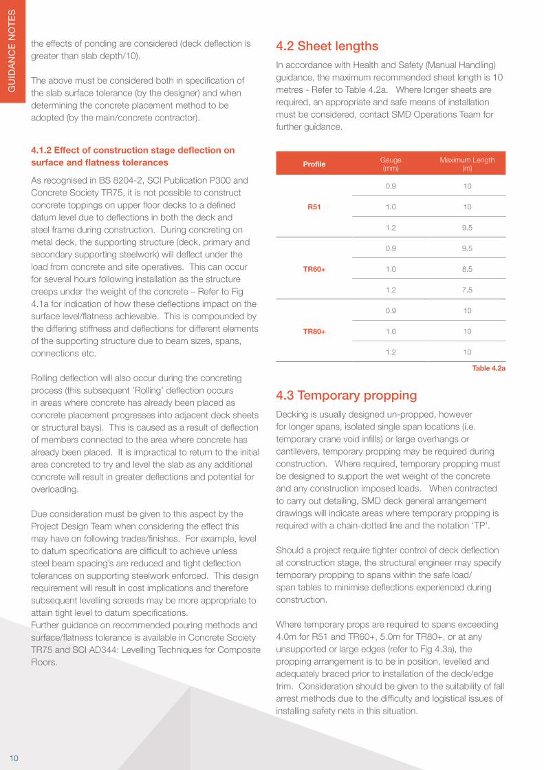
4.2 Sheet lengths In accordance with Health and Safety (Manual Handling) guidance,themaximumrecommendedsheetlengthis10metres - Refer to Table 4.2a. Where longer sheets are required,anappropriateandsafemeansofinstallationmustbeconsidered,contactSMDOperationsTeamforfurther guidance.
Profile Gauge(mm)
Maximum Length(m)
R51
0.9 10
1.0 10
1.2 9.5
TR60+
0.9 9.5
1.0 8.5
1.2 7.5
TR80+
0.9 10
1.0 10
1.2 10
Table 4.2a
4.3 Temporary proppingDeckingisusuallydesignedun-propped,howeverforlongerspans,isolatedsinglespanlocations(i.e.temporarycranevoidinfills)orlargeoverhangsorcantilevers,temporaryproppingmayberequiredduringconstruction.Whererequired,temporaryproppingmustbe designed to support the wet weight of the concrete and any construction imposed loads. When contracted tocarryoutdetailing,SMDdeckgeneralarrangementdrawings will indicate areas where temporary propping is required with a chain-dotted line and the notation 'TP'.
Shouldaprojectrequiretightercontrolofdeckdeflectionatconstructionstage,thestructuralengineermayspecifytemporary propping to spans within the safe load/spantablestominimisedeflectionsexperiencedduringconstruction.
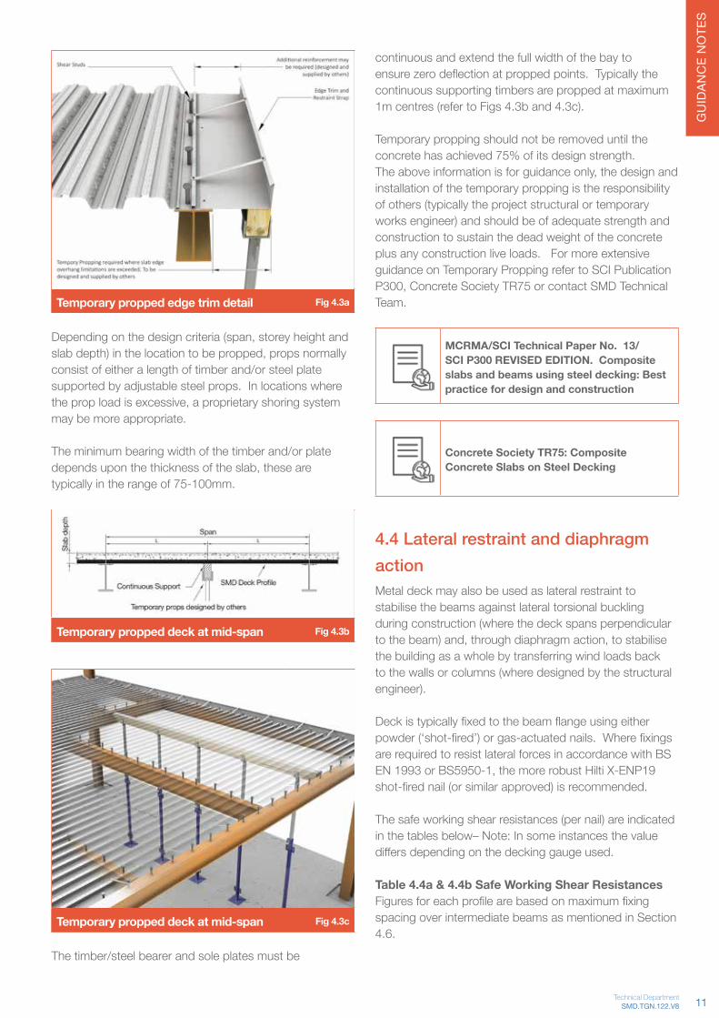
Where temporary props are required to spans exceeding 4.0mforR51andTR60+,5.0mforTR80+,oratanyunsupportedorlargeedges(refertoFig4.3a),theproppingarrangementistobeinposition,levelledandadequately braced prior to installation of the deck/edge trim. Consideration should be given to the suitability of fall arrestmethodsduetothedifficultyandlogisticalissuesofinstalling safety nets in this situation.
10
GU
IDAN
CE
NO
TES
Temporary propped edge trim detail Fig 4.3a
Dependingonthedesigncriteria(span,storeyheightandslabdepth)inthelocationtobepropped,propsnormallyconsist of either a length of timber and/or steel plate supported by adjustable steel props. In locations where theproploadisexcessive,aproprietaryshoringsystemmay be more appropriate.
The minimum bearing width of the timber and/or plate dependsuponthethicknessoftheslab,thesearetypically in the range of 75-100mm.
Temporary propped deck at mid-span Fig 4.3b
Temporary propped deck at mid-span Fig 4.3c
The timber/steel bearer and sole plates must be
continuous and extend the full width of the bay to ensurezerodeflectionatproppedpoints.Typicallythecontinuous supporting timbers are propped at maximum 1m centres (refer to Figs 4.3b and 4.3c).
Temporary propping should not be removed until the concrete has achieved 75% of its design strength.Theaboveinformationisforguidanceonly,thedesignandinstallation of the temporary propping is the responsibility of others (typically the project structural or temporary works engineer) and should be of adequate strength and construction to sustain the dead weight of the concrete plus any construction live loads. For more extensive guidance on Temporary Propping refer to SCI Publication P300,ConcreteSocietyTR75orcontactSMDTechnicalTeam.
MCRMA/SCI Technical Paper No. 13/SCI P300 REVISED EDITION. Composite slabs and beams using steel decking: Best practice for design and construction
Concrete Society TR75: Composite Concrete Slabs on Steel Decking
4.4 Lateral restraint and diaphragm actionMetal deck may also be used as lateral restraint to stabilise the beams against lateral torsional buckling during construction (where the deck spans perpendicular tothebeam)and,throughdiaphragmaction,tostabilisethe building as a whole by transferring wind loads back to the walls or columns (where designed by the structural engineer).
Deckistypicallyfixedtothebeamflangeusingeitherpowder(‘shot-fired’)orgas-actuatednails.Wherefixingsare required to resist lateral forces in accordance with BS EN1993orBS5950-1,themorerobustHiltiX-ENP19shot-firednail(orsimilarapproved)isrecommended.
The safe working shear resistances (per nail) are indicated in the tables below– Note: In some instances the value differsdependingonthedeckinggaugeused.
Table 4.4a & 4.4b Safe Working Shear ResistancesFiguresforeachprofilearebasedonmaximumfixingspacing over intermediate beams as mentioned in Section 4.6.
11SMD.TGN.122.V8Technical Department

GU
IDAN
CE
NO
TES
Hilti X-U-15 fixings (DAK pin)Deck Gauge
Profile (kN) 0.9mm 1.0mm 1.2mm
Per nail 0.80 0.80 0.80
R51 1.33 1.33 1.33
TR60+ 1.20 1.20 1.20
TR80+ 1.33 1.33 1.33
Table 4.4a
Hilti X-ENP 19 fixings (heavy duty nail)Deck Gauge
Profile (kN) 0.9mm 1.0mm 1.2mm
Per nail 2.90 3.20 4.00
R51 4.83 5.33 6.66
TR60+ 4.35 4.80 6.00
TR80+ 4.83 5.33 6.66
Table 4.4b
Hilti X-P14 G3 MX fixings (gas nail)Deck Gauge
Profile (kN) 0.9mm 1.0mm 1.2mm
Per nail 0.40 0.40 0.40
R51 0.67 0.67 0.67
TR60+ 0.60 0.60 0.60
TR80+ 0.67 0.67 0.67
Table 4.4c
Refer to SCI Publication 093 and SCI Advisory Desk Note AD 175, BS EN 1993 or BS5950-9 for more information
4.5 Bearings / Support
4.5.1 End bearing
The minimum bearing requirements for the decking are 50mm on steelwork (this is increased to 60mm where sheetsaretoreceivethru-deckweldedshearstuds,referto Composite Beam section of this document) and 70mm on masonry or concrete.
Where the deck is to butt up against a concrete core or similar,shelfanglesaretobeinstalledbyotherstoprovideadequate end bearing for the metal deck (refer to Fig 4.5a).Whendevelopingsuchadetail,considerationmust
be given to the height of any continuity reinforcement extending from the core to ensure it does not clash with thetroughsofthedeckprofile.
Deck on RSA fixed to concrete core Fig.4.5a
4.5.2 Shelf Angles or bottom flanges
To reduce the structural zone it is sometimes necessary toinstallthedeckingontoanglesfixedtothebeamwebsorbottomflanges.Wheredeckendsaresupportedonshelfanglesorbottomflangesbetweenbeamwebs,theshelfangleorbottomflangesmustbedesignedtoextenda minimum of 50mm beyond the toe of the beam top flange.Thisminimumdimensionof50mmisessentialto enable the sheets to be physically positioned between toesoftopflangesandprovideaccessforacartridgetoolto be used to secure the decking into place (refer to Fig 4.5b).
SMD.DOD.177.V2
Sla
b de
pth
Example of deck being placed onto shelf angles
Desired position of deckSMD Deck Profile
Typical50 min.
Typical50 min.
End Caps for TR profiles or Tape (R51)
SMD require sufficient clearance between the toe of thetop flange and the support steel inside the beam flange(a) to enable the deck to be placed inside the beam weband also for access (b) to install the end caps (TRprofiles) or tape (R51) to close of the gaps in the end ofthe troughs.
a
b
Typical50 min.
Decking Bearing of Shelf Angle Detail
Deck placed on angles in beams Fig.4.5b
Where the deck spans parallel to the beam web a structural support angle is the recommended detail (refer to Fig 4.5c). It may be possible depending on spacing ofsecondarybeamstoutilisea2.0mmgaugeflashingtoavoidtherequirementforastructuralangle,howeverthis will impact on the slab capacity for high concentrated loadslocallyintheregionofthenon-structuralflashing.
Refer to SMD Data sheet SMD.DOD.177 - Decking Bearing of Shelf Angle Detail at www.smdltd.co.uk
12
GU
IDAN
CE
NO
TES
Deck runing in each orientation Fig.4.5c
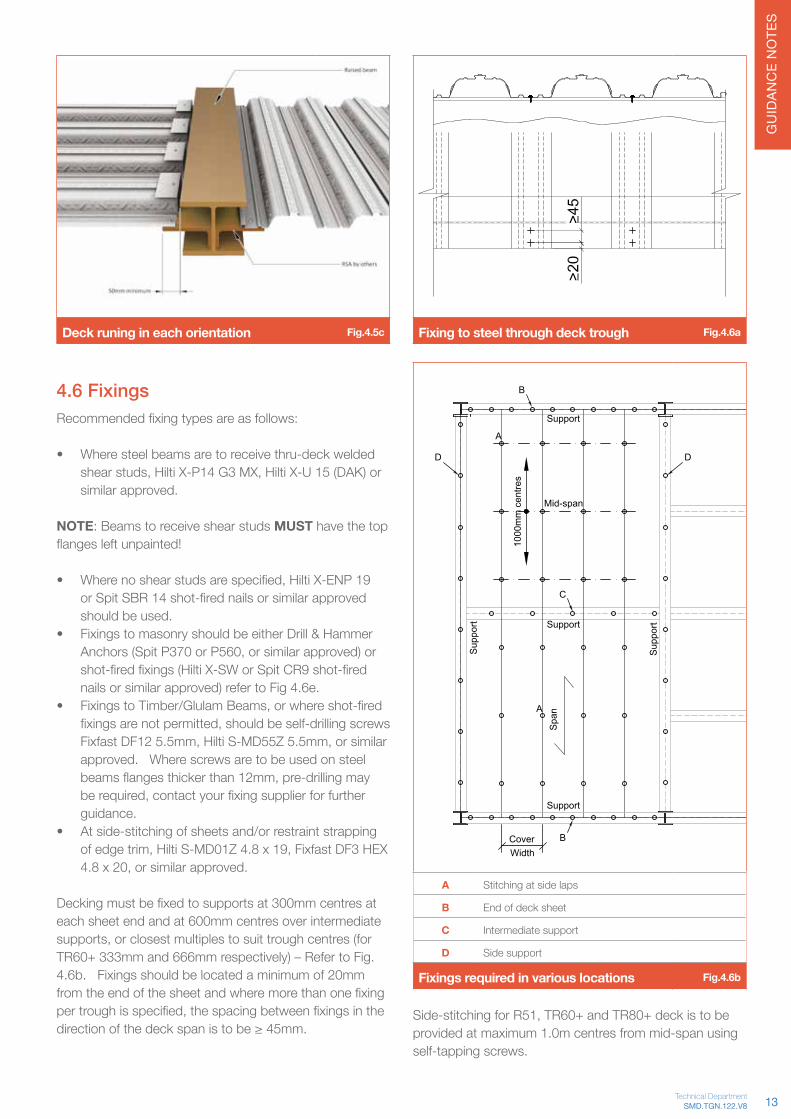
4.6 FixingsRecommendedfixingtypesareasfollows:
• Where steel beams are to receive thru-deck welded shearstuds,HiltiX-P14G3MX,HiltiX-U15(DAK)orsimilar approved.
NOTE: Beams to receive shear studs MUST have the top flangesleftunpainted!
• Wherenoshearstudsarespecified,HiltiX-ENP19orSpitSBR14shot-firednailsorsimilarapprovedshould be used.
• Fixings to masonry should be either Drill & Hammer Anchors(SpitP370orP560,orsimilarapproved)orshot-firedfixings(HiltiX-SWorSpitCR9shot-firednails or similar approved) refer to Fig 4.6e.
• FixingstoTimber/GlulamBeams,orwhereshot-firedfixingsarenotpermitted,shouldbeself-drillingscrewsFixfastDF125.5mm,HiltiS-MD55Z5.5mm,orsimilarapproved. Where screws are to be used on steel beamsflangesthickerthan12mm,pre-drillingmayberequired,contactyourfixingsupplierforfurtherguidance.
• At side-stitching of sheets and/or restraint strapping ofedgetrim,HiltiS-MD01Z4.8x19,FixfastDF3HEX4.8x20,orsimilarapproved.
Deckingmustbefixedtosupportsat300mmcentresateach sheet end and at 600mm centres over intermediate supports,orclosestmultiplestosuittroughcentres(forTR60+ 333mm and 666mm respectively) – Refer to Fig. 4.6b. Fixings should be located a minimum of 20mm fromtheendofthesheetandwheremorethanonefixingpertroughisspecified,thespacingbetweenfixingsinthedirectionofthedeckspanistobe≥45mm.
Fixing to steel through deck trough Fig.4.6a
CoverWidth
Support
Support
Support
Sup
port
Sup
port
R51
TR60+
TR80+
A B C D
Spacings
Mid-span
A
A
B
C
B
D D
1000
1000
1000
300
333
300
600
666
600
750
750
750
EndcapsProduct
1000
mm
cen
tres
(2)
(3)
(2) (1)
(2)
(1)
B D Straps
Spacings
Edge trim <200mm high 750 750 750
Edge trim 201mm - 300mm 750 750 500
Product
Edge trim 301mm - 450mm 750 750 250*
(No.per sheet width)
A = Side laps of decking sheetsB = End of deck sheetC = Intermediate supportsD = Side stitching
*Two sets of restraint straps are necessary (Refer Fig 16.8).
X
Spa
n
A Stitching at side laps
B End of deck sheet
C Intermediate support
D Side support
Fixings required in various locations Fig.4.6b
Side-stitchingforR51,TR60+andTR80+deckistobeprovided at maximum 1.0m centres from mid-span using self-tapping screws.
13SMD.TGN.122.V8Technical Department
GU
IDAN
CE
NO
TES
Where decking is required to provide lateral restraint and nothru-deckweldedshearstudsarespecified,thefixingtypeshouldbecheckedbytheengineer,refertosection4.4.
Refer to BS EN 1993 or BS5950 for more information
Spacings (No. per sheet width)
Profile A B C D Endcaps
R51 1000 300 (2) 600 (1) 750 X
TR60+ 1000 333 (3) 666 (2) 750 ü
TR80+ 1000 300 (2) 600 (1) 750 ü
Table 4.6a
Spacings
Edge trim B D Straps
<200mm high 750 750 750
201 - 300mm 750 750 500
301 - 450mm 750 750 250*
*Two sets of restraint straps are necessary Table 4.6b
Deck fixed to blockwork Fig.4.6e
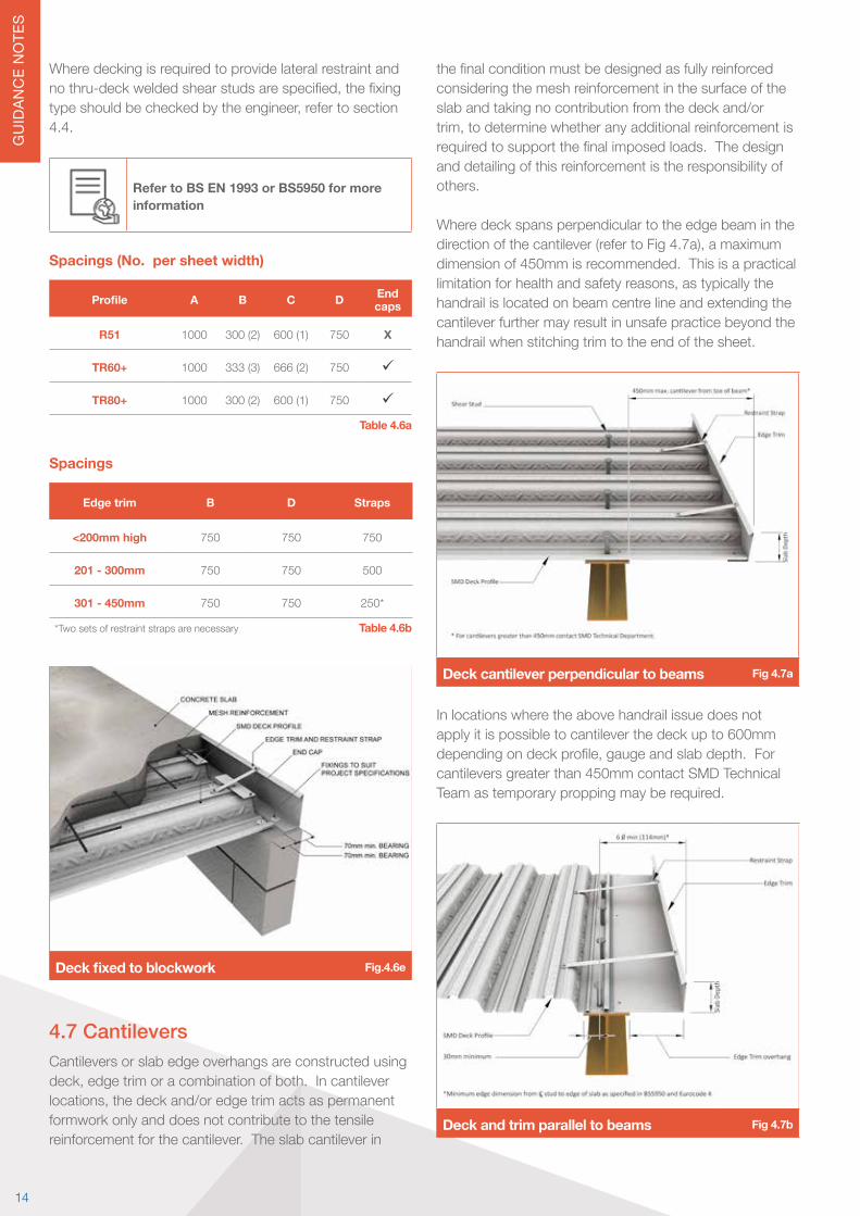
4.7 CantileversCantilevers or slab edge overhangs are constructed using deck,edgetrimoracombinationofboth.Incantileverlocations,thedeckand/oredgetrimactsaspermanentformwork only and does not contribute to the tensile reinforcement for the cantilever. The slab cantilever in
thefinalconditionmustbedesignedasfullyreinforcedconsidering the mesh reinforcement in the surface of the slab and taking no contribution from the deck and/or trim,todeterminewhetheranyadditionalreinforcementisrequiredtosupportthefinalimposedloads.Thedesignand detailing of this reinforcement is the responsibility of others.
Where deck spans perpendicular to the edge beam in the directionofthecantilever(refertoFig4.7a),amaximumdimension of 450mm is recommended. This is a practical limitationforhealthandsafetyreasons,astypicallythehandrail is located on beam centre line and extending the cantilever further may result in unsafe practice beyond the handrail when stitching trim to the end of the sheet.
Deck cantilever perpendicular to beams Fig 4.7a
In locations where the above handrail issue does not apply it is possible to cantilever the deck up to 600mm dependingondeckprofile,gaugeandslabdepth.Forcantilevers greater than 450mm contact SMD Technical Team as temporary propping may be required.
Deck and trim parallel to beams Fig 4.7b
14

GU
IDAN
CE
NO
TES
Deck spanning parallel to the edge beamCantilevers are achieved using edge trim (refer to Fig 4.7b). Decking must not be cantilevered at side locations without additional supports in place (refer to Fig 4.8c). The maximum achievable cantilever from edge of beam depends on the slab depth and edge trim gauge (refer to Table 4.7a for typical situations) up to a maximum of 200mm. For cantilevers or slab depths outside of this table contact SMD Technical Team.
Edge trim gauge
Slab depth 1.0mm 1.2mm 1.6mm 2.0mm
130mm 105mm 125mm 160mm 200mm
150mm 95mm 115mm 150mm 185mm
175mm 90mm 110mm 145mm 175mm
200mm 85mm 100mm 135mm 165mm
>250mm Propping required
Propping required
Propping required
Propping requiredTable 4.7a
4.8 Edge trimGalvanised edge trim is provided where requested around perimeter and void edges. This edge trim acts as permanent formwork only to support the wet weight of concrete during construction.
Extract Clause 9.6.18 from NSSS Fig.4.8a
Depending on the structure of the design team for the contract,theedgedimensionswilltypicallybeprovidedbyeither the architect or structural engineer. In accordance withtheNationalStructuralSteelworkSpecification(NSSS) the tolerance on trim position is +/-10mm from CL ofbeam,thisisinadditiontotheacceptabletoleranceforthe perimeter steelwork.
Refer to National Structural Steelwork Specification (NSSS) 5th Edition for more information
In some instances tighter tolerances may be required tosuitthecladdingcontractor.Wherethisisthecase,positions for edge trim should be engineered on site by a site engineer either by advising dimensions from constructed steel position or marking a physical line for theoretical grid position on site to enable the edge trim to be installed accurately from this position and hence reducing the impact of perimeter steel tolerance on slab edgeposition.However,considerationshouldbegiventothe appropriate gauge of edge trim to accommodate this setting out.
Typically,edgetrimissuppliedtositeinlengthsof3.0mwhere it is then cut to suit. Edge trims are available in varyinggauges;1.0mm,1.2mm,1.6mmand2.0mm.Thematerial gauge is determined by the depth of the concrete slab and the extent of the slab overhang (refer to Table 4.7a).Edgetrimcanbeeitherfixedtotheendofthedecking with self-tapping screws (refer to Fig 4.7a) or to themainsupportingstructure,usingsimilarfixingsasthatused to secure the decking (refer to Fig 4.8c).
R51 slab edge and flashings Fig.4.8b
The minimum bearings for edge trim are similar to that forthefloordeck;50mmonsteelworkor70mmformasonryorconcretesupports.Edgetrimshouldbefixedto supports at both ends and maximum 750mm centres alongthelengthofthepieceofedgetrim,withrestraintstrapsfixedbetweenthetopedgeoftheverticallegandthefloordeckat750mmcentres(typical),or500mmcentres for slab depths between 200-300mm (refer to Fig 4.8b).
Whereslabdepth/edgetrimheightexceeds300mm,two levels of restraint straps may be required alternated
15SMD.TGN.122.V8Technical Department
GU
IDAN
CE
NO
TES
between the top edge of the vertical leg and mid-height (refer to Fig.4.8d). 4.8.1 Alternative detail for large overhangs or cantilevers
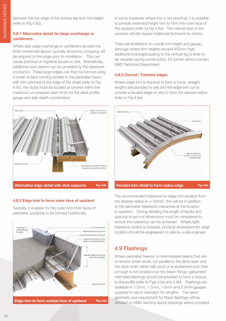
Where slab edge overhangs or cantilevers exceed the limitsmentionedabove,typicallytemporaryproppingwillbe required to the edge prior to installation. This can causepracticalorlogisticalissuesonsite.Alternatively,additional stub beams can be provided by the steelwork contractor. These large edges can then be formed using asheetofdeckrunningparalleltotheperimeterbeam,with trim stitched to the edge of the sheet (refer to Fig 4.8c),thestubsmustbelocatedatcentreswithinthemaximumun-proppedspanlimitsforthedeckprofile,gauge and slab depth combination.
Alternative edge detail with stub supports Fig 4.8c
4.8.2 Edge trim to form outer face of upstand
Typically,itiseasierfortheouterandinnerfacesofperimeter upstands to be formed traditionally.
Edge trim to form outside face of upstand Fig.4.8d
Insomeinstanceswherethisisnotpractical,itispossibleto provide extended height trim to form the outer face of the upstand (refer to Fig 4.8d). The internal face of the upstand will still require traditional formwork by others.
Therearelimitationsonoveralltrimheightandgauge,althoughwheretrimheightsexceed450mmhigh,additional bracing/propping to the vertical leg is likely to berequiredduringconstruction,forfurtheradvicecontactSMD Technical Department. 4.8.3 Curved / Faceted edges
Whereedgetrimisrequiredtoformacurve,straightlengths are provided to site and the edge trim cut to provide a faceted edge on site to form the desired radius (refer to Fig 4.8e).
Faceted trim detail to form radius edge Fig.4.8e
The recommended tolerance for edge trim position from thedesiredradiusis+/-25mm,thiswillbeinadditionto the perimeter steelwork tolerances at the location in question. During detailing the length of facets and spacing of set-out dimensions must be considered to ensure this tolerance can be achieved. Where tight tolerancecontrolisrequired,physicaldimensionsforedgelocation should be engineered on site by a site engineer.
4.9 FlashingsWhereperimeterbeams,orintermediatebeamsthataretoreceiveshearstuds,runparalleltothedeckspanandthe deck width either falls short or is positioned such that atroughisnotlocatedoverthebeamflange,galvanisedmildsteelflashingsshouldbeprovidedtoformaclosuretotheprofile(refertoFigs4.9aand4.9b).Flashingsareavailablein1.0mm,1.2mm,1.6mmand2.0mmgauges;supplied to site in standard 3m lengths. The exact geometryandrequirementfortheseflashingswillbedetailed on SMD decking layout drawings where provided.
16

GU
IDAN
CE
NO
TES
Flashing detail at perimeter beam Fig.4.9b
4.10 Steps in slabWhereastepinthedeck/slablevelisrequired,thisshouldbelocatedatsupportingbeampositions,withanglesprovided to support the lower level decking.
Dependingonthedifferenceinlevelandrequirementforslabcontinuity,thehigherlevelslabmaybeformedusing standard edge trim (refer to Fig 4.10a) or formed traditionally by following trades (refer to Fig 4.10b).
Step in slab formed with edge trim Fig.4.10a
Step in slab formed traditionally Fig.4.10b
Whendevelopingthedetailtobeused,thebuildabilityshould be considered as the detail in Fig 4.10b would requireatwostageconcretepour,withthelowerlevelpouredfirst.
4.11 End capsWhere trapezoidal (TR60+ or TR80+) decking sheets endattheperimeterofthebuildingoratinternalvoids,the ends of the sheets are sealed with 0.7mm gauge galvanised end caps or polystyrene inserts. These end caps will also be required where you have a change in span direction (refer to Fig 4.11a). Due to the small re-entrantribsizeoftheR51profile,sheetsaretypicallysealed using tape or expandable foam.
End caps Fig.4.11a
17SMD.TGN.122.V8Technical Department
GU
IDAN
CE
NO
TES
Technical Guidance Notes
5.0 Design - Floor deck - Composite stageDuringtheComposite,orNormalStage,thecompositeslab must be checked for super-imposed Permanent (Dead)andVariableImposed(Live)loadsasspecifiedby the client / engineer. Composite slabs are usually designed as a series of simply supported slabs in accordance with BS EN 1994-1-1 or BS5950-4.
Concentrated loads (i.e. line loads from walls) should be checkedseparatelytoensurethespecifiedslabcriteriaisadequatefortherequiredloadings.Specificchecksfor concentrated loads can be carried out using SMD Elements® design software.
Duringdesignofthecompositeslab,considerationshouldbe given to any loadings that may be applied to the slab during the construction phase (i.e. concentrated loads fromplantormaterialstorage),asthesemaybemoreonerous than the design loadings for the intended building use and impact on the minimum reinforcement required.
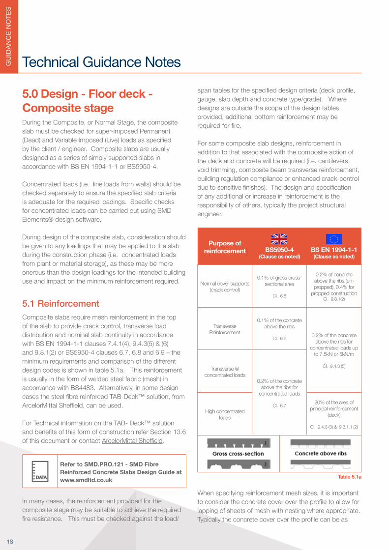
5.1 ReinforcementComposite slabs require mesh reinforcement in the top oftheslabtoprovidecrackcontrol,transverseloaddistribution and nominal slab continuity in accordance withBSEN1994-1-1clauses7.4.1(4),9.4.3(5)&(6)and9.8.1(2)orBS5950-4clauses6.7,6.8and6.9–theminimumrequirementsandcomparisonofthedifferentdesign codes is shown in table 5.1a. This reinforcement is usually in the form of welded steel fabric (mesh) in accordancewithBS4483.Alternatively,insomedesigncasesthesteelfibrereinforcedTAB-Deck™solution,fromArcelorMittalSheffield,canbeused.
For Technical information on the TAB- Deck™ solution andbenefitsofthisformofconstructionreferSection13.6of this document or contact ArcelorMittalSheffield.
Refer to SMD.PRO.121 - SMD Fibre Reinforced Concrete Slabs Design Guide at www.smdltd.co.uk
Inmanycases,thereinforcementprovidedforthecomposite stage may be suitable to achieve the required fireresistance.Thismustbecheckedagainsttheload/
spantablesforthespecifieddesigncriteria(deckprofile,gauge,slabdepthandconcretetype/grade).Wheredesigns are outside the scope of the design tables provided,additionalbottomreinforcementmayberequiredforfire.
Forsomecompositeslabdesigns,reinforcementinaddition to that associated with the composite action of thedeckandconcretewillberequired(i.e.cantilevers,voidtrimming,compositebeamtransversereinforcement,building regulation compliance or enhanced crack-control duetosensitivefinishes).Thedesignandspecificationof any additional or increase in reinforcement is the responsibilityofothers,typicallytheprojectstructuralengineer.
Purpose of reinforcement BS5950-4
(Clause as noted)BS EN 1994-1-1(Clause as noted)
Normal cover supports (crack control)
0.1% of gross cross-sectional area
CI. 6.8
0.2% of concrete above the ribs (un-propped),0.4%for
propped construction CI. 9.8.1(2)
Transverse Reinforcement
0.1% of the concrete above the ribs
CI. 6.9 0.2% of the concrete above the ribs for
concentrated loads up to 7.5kN or 5kN/m
CI. 9.4.3 (5)Transverse @ concentrated loads
0.2% of the concrete above the ribs for
concentrated loads
CI. 6.7High concentrated
loads
20% of the area of principal reinforcement
(deck)
CI. 9.4.3 (3) & 9.3.1.1 (2)
Table 5.1a
Whenspecifyingreinforcementmeshsizes,itisimportanttoconsidertheconcretecoverovertheprofiletoallowforlapping of sheets of mesh with nesting where appropriate. Typicallytheconcretecoverovertheprofilecanbeas
18
GU
IDAN
CE
NO
TES
littleas60mm.Wherethisisthecase,theuseofmeshreinforcementwithflyingendsmaybenecessarytoenablethe top cover dimension to the mesh to be achieved.
The detailing of all reinforcement within the composite slab is the responsibility of the slab designer.
Although cracks do not normally pose a durability or serviceabilityhazard,thereareinstanceswherethecompositefloorslabisrequiredtoprovideawearingsurfaceorreceivesappliedfinishesthatmaybesensitiveto cracking. Reinforcement percentages in excess of 0.3% are likely to be required to limit crack widths to an acceptable level.
Refer to SMD Elements® design software at www.smdltd.co.uk
Refer to Eurocode NCCI PN005c-GB or more information
Refer to SCI Publication P-056 (BS5950 Design) or more information
5.2 Saw cutsAlthough the formation of saw cuts is a recognised methodofcontrollingcracksongroundslabs,itisnotrecommendedforupperfloorslabsonmetaldeckforanumberofreasons,includingthedangerofseveringmeshthatiscriticalforthecompositeslabfiredesign.Fromexperience saw cuts do not always perform the intended function of concentrating the cracking in the location expected.
The preferred method of controlling cracking in composite slabs is through an increase in reinforcement percentage in the top of the slab.
Refer to SCI AD347: Saw Cutting of Composite Slabs to Control Cracking for more information
MCRMA/SCI Technical Paper No. 13/SCI P300 REVISED EDITION. Composite slabs and beams using steel decking: Best practice for design and construction
Refer to BS EN 1992-1-1 Section 7.3for more information
Refer to Concrete Society TR75: Composite Concrete Slabs on Steel Decking for more information
Refer to AD150: Composite Floors – Wheel Loads from Forklift Trucks for more information
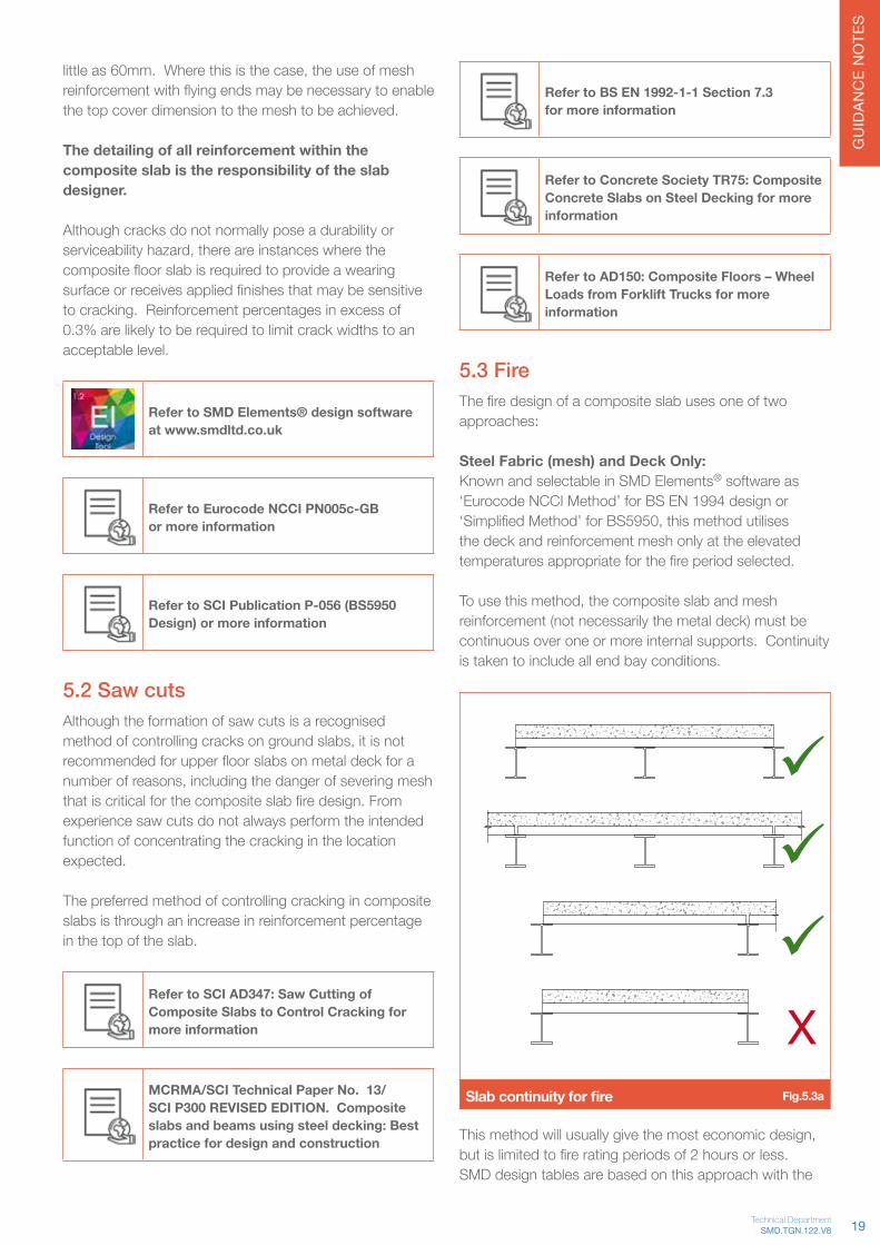
5.3 FireThefiredesignofacompositeslabusesoneoftwoapproaches:
Steel Fabric (mesh) and Deck Only:Known and selectable in SMD Elements® software as ‘Eurocode NCCI Method’ for BS EN 1994 design or ‘SimplifiedMethod’forBS5950,thismethodutilisesthe deck and reinforcement mesh only at the elevated temperaturesappropriateforthefireperiodselected.
Tousethismethod,thecompositeslabandmeshreinforcement (not necessarily the metal deck) must be continuous over one or more internal supports. Continuity is taken to include all end bay conditions.
Slab continuity for fire Fig.5.3a
Thismethodwillusuallygivethemosteconomicdesign,butislimitedtofireratingperiodsof2hoursorless.SMD design tables are based on this approach with the
ü
ü
üX
19SMD.TGN.122.V8Technical Department

GU
IDAN
CE
NO
TES
slab continuous at one end only. It is important to note this when utilising the tables provided.
Refer to SMD Elements® design software to create calculations
Fire engineering method:Known (and selectable in SMD Elements® software) as ‘Eurocode Standard Method’ for BS EN 1994 design or ‘FireEngineering’forBS5950,thismethodusesadditionalreinforcement in the troughs of the decking along with top mesh reinforcement (where slab continuity permits) to achievetherequiredfirerating.Wherethecompositeslabistruesinglespan(i.e.noslabcontinuityateitherend),this method should be used.
Single span slab - fire engineering Fig.5.3b
SMD Elements® design software enables the user to check designs using any of these methods to suit the design standard chosen.
Forextensiveguidanceonthefiredesignmethodsmentionedabove,refertoEurocodeNCCIPN005c-GBfor Eurocode and SCI Publication Publication P-056 for BS5950 design.
The recommended top cover to the mesh reinforcement is a minimum of 15mm and a maximum of 45mm to ensure themeshiseffectiveforboththefireandcrack-controlrequirements,refertoFig.5.3c.Duetothemodularsizeof spacers available and relatively thin concrete depth overthetopofthedeckrib,insomeinstances,itmaybenecessary to position the reinforcement directly on the top ofthedeckrib.Wherethisisproposed,itisimportantthat the composite slab design is checked to ensure this doesnotaffectthefiredesignfortheslabdesigncriteriain consideration and that the top cover to reinforcement does not compromise the crack-control provided.
Recommended reinforcement cover Fig.5.3c
For minimum mesh lap requirements refer to BS EN 1992-1-1orBS8110.Generally,minimumlapsshouldbe300mmforA142and400mmforA193,A252andA393.The mesh must satisfy the elongation requirements ofBS4449,formorespecificguidancerefertoSCIPublication P300 – Composite Slabs and Beams using Steel Decking: Best Practice for Design and Construction.In addition to the requirements of Eurocode NCCI PN005-GB,BSEN1994-1-2orBS5950-4withregardtostructuralbehaviourundernormaldesignloads,theslab must also meet the minimum insulation requirement specifiedinBS5950Part8,EurocodeNCCIPN005-GBorBS EN 1994-1-2.
Refer SMD Product Data sheets for minimum insulation thicknesses appropriate to each profile
Firestop Fillers
Insomesituations,dependingonthebeamfiredesignandprotection,firestopfillerswillberequiredintheribsofthedeckprofileoverthebeamflanges-ReferSCIPublicationP300Table5.2.Whererequired,thesearetypically installed by following trades.
5.4 Moving concentrated loads5.4.1 Critical design cases Formovingconcentratedloadswithtypicaldesigncriteria,the common mode of failure is Horizontal Shear Failure atthedeck/concreteinterface,itisthereforeessentialtocheck the slab for:1. Worstcasebendingatfirestage(withloadpositioned
at mid-span)
Concentrated load - worst case bending Fig 5.4a
ü
20

GU
IDAN
CE
NO
TES
2. Worst case shear at composite stage (with load positioned adjacent to the support)
Concentrated load - worst case shear Fig 5.4b
Whendesigningforconcentratedloads,itisimportantto consider those that may be applied from plant during construction,asthesemaybemoreonerousthanthefinalspecifiedloadingsforthebuildingandwillimpactonthereinforcement required for the slab.
5.4.2 Typical plant that can be used on the slab during constructionTherearemanydifferentmakesandmodelsofplant(scissor lift or cherry picker) that can be used during the projectconstructionphase,allofwhichhavedifferingweights,wheelbasesandworstcasepointloads.
HR12 GS1930 NANOSP(4.5m)
Length (mm) 3500 1320 1200
Width (mm) 1600 815 750
Vehicle Weight (kg) 3470 1503 478
Working load (kg) 200 272 200
Total Weight (kg) 3670 1775 678
Max Point load (kN) 21.6 10.4 4.0
Other Point load (kN) 4.8 2.3 0.9Table 5.4a
Theacceptableuseofplantdependsonthespecificdesigncriteria(i.e.spans,profile,slabdepthetc).Table
5.4b covers the use of Plant on a cured slab during the constructionstage,indicatingacceptablespansforthreepiecesofplantclassifiedaslight(NANOSP),medium(GS1930)andheavy(HR12)asdefinedinTable5.4a.
Slab Depth (mm)
Profile Gauge 130 140 150 175 200
HR1
2 M
EWP
R51
0.9 2.20 2.85 2.80 2.65 2.50
1.0 2.35 3.10 3.05 2.85 2.70
1.2 2.40 3.40 3.30 3.15 3.00
TR60+
0.9 - - - - 1.90
1.0 - - - - 2.10
1.2 - - - - 2.20
TR80+
0.9 - - - - 1.50
1.0 - - - - 1.60
1.2 - - - - 1.50
Gen
ie G
S193
0R51
0.9 2.95 2.85 2.80 2.65 2.50
1.0 3.20 3.10 3.05 2.85 2.70
1.2 3.40 3.40 3.30 3.15 3.00
TR60+
0.9 1.20 1.90 2.95 2.95 2.75
1.0 1.20 1.90 2.95 3.25 3.05
1.2 1.20 1.90 2.95 3.80 3.55
TR80+
0.9 - 1.35 2.10 3.80 3.55
1.0 - 1.35 2.10 4.15 3.90
1.2 - 1.35 2.10 4.65 4.50
NAN
OSP
(4.5
m)
R51
0.9 2.95 2.85 2.80 2.65 2.50
1.0 3.20 3.10 3.05 2.85 2.70
1.2 3.40 3.40 3.30 3.15 3.00
TR60+
0.9 3.40 3.30 3.20 2.95 2.75
1.0 3.75 3.60 3.50 3.25 3.05
1.2 4.20 4.05 3.95 3.80 3.55
TR80+
0.9 - 4.25 4.10 3.80 3.55
1.0 - 4.50 4.40 4.15 3.90
1.2 - 5.10 4.95 4.65 4.50Table 5.4b
These tables are based on the following design assumptions:1. All spans designed as un-propped during
construction2. This table considers Eurocode design only.3. Minimum mesh area greater than 0.2% of the cross
sectional area of the slab (BS EN 1994-1-1: 9.8.1)4. 1.5kN/m2 construction load applied. No additional
loads considered5. 1hrfirerating6. Wheel sizes assumed as 100x100mm 7. C25/30 Concrete Grade8. Max point load taken as 60% of Total Weight
21SMD.TGN.122.V8Technical Department
GU
IDAN
CE
NO
TES
Important Note: Where Plant is required during the life ofthebuilding,thefollowingtablesdonotapplyandadditional reinforcement may be required for serviceability due to the increased duration of wheel loads and higher imposed loads.
Refer SCI Advisory Desk Note 150: Composite Floors – Wheel loads from Forklift Trucks
Refer to Concrete Society TR75: Composite Concrete Slabs on Steel Decking for more information
5.5 Long single span propped composite slabsFollowing research into long single span propped composite slabs (i.e. locations where the slab is not continuousoversupportsateitherendofthespan,typicallyfoundinlightgaugeframeconstruction),designguidance was published by SCI/NHBC in New Steel Construction (October 2011). The guidance introduces more stringent span/depth ratios when long single span slabs require propping. When using SMD Elements® software,aguidancenotewillappearcontainingalinktothe SCI/NHBC guidance where the input design criteria is appropriate. For further guidance contact SMD Technical Team.
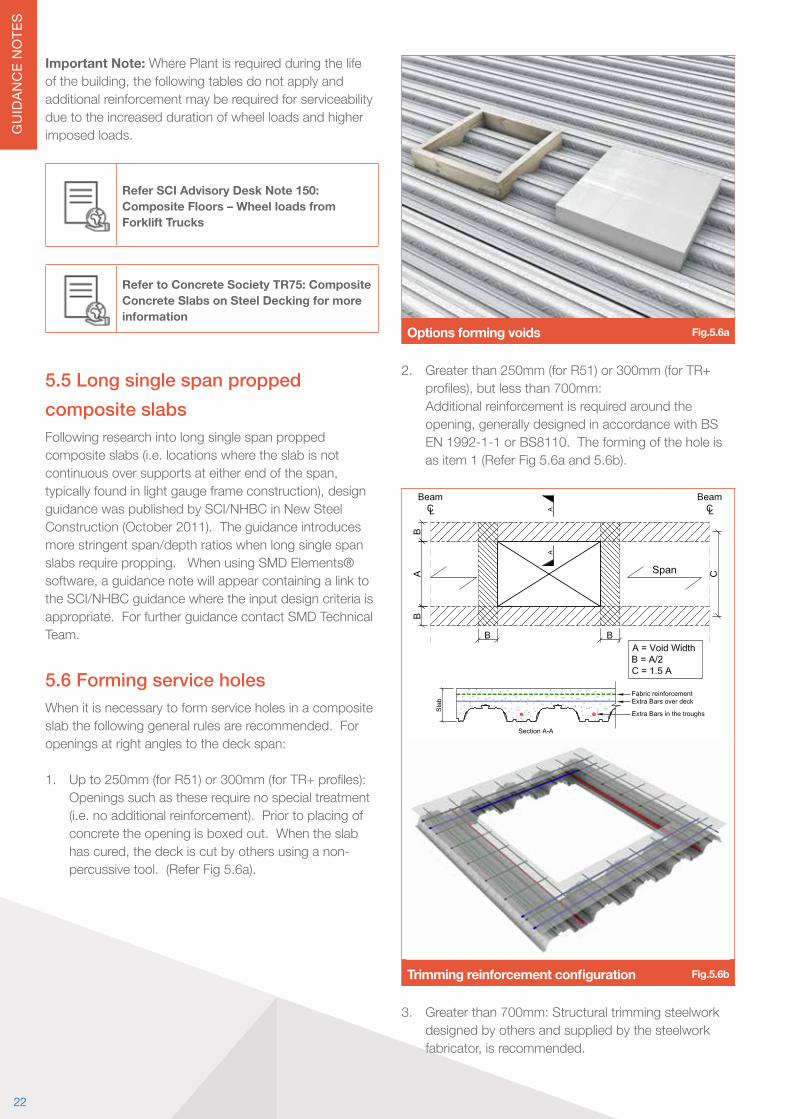
5.6 Forming service holesWhen it is necessary to form service holes in a composite slab the following general rules are recommended. For openings at right angles to the deck span:
1. Upto250mm(forR51)or300mm(forTR+profiles):Openings such as these require no special treatment (i.e. no additional reinforcement). Prior to placing of concrete the opening is boxed out. When the slab hascured,thedeckiscutbyothersusinganon-percussive tool. (Refer Fig 5.6a).
Options forming voids Fig.5.6a
2. Greater than 250mm (for R51) or 300mm (for TR+ profiles),butlessthan700mm:
Additional reinforcement is required around the opening,generallydesignedinaccordancewithBSEN 1992-1-1 or BS8110. The forming of the hole is as item 1 (Refer Fig 5.6a and 5.6b).
Trimming reinforcement configuration Fig.5.6b
3. Greater than 700mm: Structural trimming steelwork designed by others and supplied by the steelwork fabricator,isrecommended.
22

GU
IDAN
CE
NO
TES
Items 1 and 2 relate to holes in isolation and not to a seriesofholestransversetothedirectionofspan,whichshouldbeconsideredasonelargevoid.Inthesecases,the metal decking should only be cut after the slab has cured.Typically,foravoidtobeconsideredinisolation,the clear dimension between void edges in a direction transverse to the deck span should be no less than the greaterof666mmor1.5xvoidwidth(AinFig5.6b),providing no excessive concentrated loads apply to the unsupported edges.
Void Size TR60+ & TR80+ R51
SmallUp to 300mm
No additional measures required
Up to 250mmNo additional measures
required
Meduim300-700mm
Additional reinforcement required
250-700mmAdditional reinforcement
required
Large >700mmStructural trimming steel required (Fig 5.6b)
Table 5.6c
These are guidelines only and particular requirements should be checked by the project structural engineer.
Need Further Guidance? Contact us on +44 (0)1202 718 898 or email our Technical Team on [email protected]
Visit www.smdltd.co.uk to access all the information in this document on our wiki pageTGNOnline
SMD’s responsibility excludes the design of any additional framing or slab reinforcement for holes or openings.
Whenformingholesinthedecking,considerationneedsto be given to Health & Safety. Due consideration should be given to protect against falling through holes. If possible,handrailsshouldbeerectedaroundthevoid.Alternatively,SMDcanprovide:• Atemporarycovertotheopening,bydeckingover
thevoid(unconcreted),forremovalbyothersatalaterdate.
• VoidSafe™ Protection System - Refer Section 13.3
Refer to VoidSafe™ Protection System Brochure at www.smdltd.co.uk
MCRMA/SCI Technical Paper No. 13/SCI P300 REVISED EDITION. Composite slabs and beams using steel decking: Best practice for design and construction
23SMD.TGN.122.V8Technical Department
Design and Installation Supportfor Floor and Roof DeckGuidanceonCertification,Specification,Health&Safety,Design,Delivery,Installation,Concrete,ProductOptionsandReferences
Toaccessthisinformation,pleasevisitwww.smdltd.co.uk/TGN
Connect with us
TGNOnline
TGNOnline
Technical Guidance Notes
Technical Guidance Notes
24
GU
IDAN
CE
NO
TES
Technical Guidance Notes
current ‘catch all’ rules contained in both BS EN 1994-1-1 and BS5950-3 Section 3.1:1990 +A1 2010.
The SCI/BCSA research provides the designer with advanced rules that cover wider design criteria than thatcurrentlyavailableintherelevantdesignstandards,including:
• Unpropped construction• Partially utilised beams• Beams with large web openings
Refer to SCI Publication P405: Minimum degree of shear connection rules forUK construction to Eurocode 4
6.3 Shear stud reduction factorsMethods for determining the resistance of shear studs in solid concrete are outlined in BS EN 1994-1-1 and BS5950-3 Section 3.1:1990 +A1 2010. When used in compositedeckedslabs,thesesolidslabstudresistancesmay need to be reduced due to the decking geometry and/or orientation.
6.4 BS EN 1994-1-1 Reduction factors for SMD productsThesefiguresarecalculatedinaccordancewithlatestSCI Publication P405 and NCCI document PN001a-GB: Resistance of headed stud shear connectors in transverse sheeting. kmod(modificationfactorfromTable2.1 of PN001a) is already applied to TR+ values where appropriate. The factors in this table should be applied to the minimum resistance for a stud in a solid slab from equations (6.18) and (6.19) of BS EN 1994-1-1.
R51 TR60+ TR80+1
Deck gauge ≤1.0mm >1.0mm ≤1.0mm >1.0mm ≤1.0mm >1.0mm
1 stud(per trough) 0.85 1.0 0.85 1.0 0.62 0.62
2 studs(per trough) 0.7 0.8 0.49 0.52 0.31 0.31
Parallel to rib2 1.0 1.0 0.9 0.9 0.53 0.53
Table 6.4a1 Figures are based on 95mm LAW shear studs except TR80+ which is based on 120mm LAW.2 Allfactorsarebasedon‘meshatnominaltopcover’,exceptParallelwhich is based on ‘below head of stud’
6.0 Design - Floor deck - Composite beam designThru-deck welded shear studs are commonly used to transfer horizontal shear forces between the steel beam and concrete slab to suit the relevant design standard. These studs are welded to the supporting beams through troughsinthedecking.Therefore,itisessentialthatthedecking and beam geometries are considered by the structuralengineerwhenspecifyingstudquantities,inparticular on beams running perpendicular to the decking span.
Forabeamtobestudwelded,theflangethicknessmustbe a minimum of 0.4 x the stud diameter = 7.6mm for the standard 19mm diameter studs used in composite beam design,toavoiddamagetothebeamflange(knownasburn through).
Wherepossible,shearstudsshouldbeplacedonthecentre line of the beam directly over the web to avoid burn through.
6.1 Shear stud LAW (length after weld)Wheninstallingshearstuds,thelengthafterweldshouldextend at least 35mm above the top of the main ribs in thedeckprofile.Therefore,theminimumstudheightafterweld should be 95mm for TR60+ or R51 and 115mm for TR80+. The recommended minimum concrete cover tothetopofthestudis15mm,thisshouldbeincreasedto 20mm if the shear stud is to be protected against corrosion,asspecifiedinBS5950-4.
Refer to SMD Data sheet 11 at www.smdltd.co.uk
6.2 Design rules for minimum degree of connectionComposite beams with metal decking should be designed in accordance with BS EN 1994-1-1 or BS5950-3 Section 3.1:1990+A12010.However,recentindustryresearchundertaken by SCI and BCSA has resulted in non-contradictory complementary information that provides the designer with advanced rules for design of composite beams removing the conservatism that exists with the
25SMD.TGN.122.V8Technical Department

GU
IDAN
CE
NO
TES
6.5 BS5950-3 Section 3.1 Reduction factors for SMD productsThesefiguresarecalculatedinaccordancewiththelatestrevision of BS5950-3 Section 3.1:1990 +A1 2010. The factors in this table should be applied to the minimum resistance for a stud in a solid slab (Qk) from Table 5 of BS5950-3 Section 3.1:1990 +A1 2010.
R51 TR60+ TR80+1
1 stud (per trough) 1.0 0.82 0.63
2 studs (per trough) 0.8 0.45 0.34
Parallel to rib2 1.0 1.0 1.0
Table 6.5a
1 Figures are based on 95mm LAW shear studs except TR80+ which is based on 120mm LAW.2 Allfactorsarebasedon‘meshatnominaltopcover’,exceptParallelwhich is based on ‘below head of stud’
Refer to SCI Publication PN001a-GB NCCI: Resistance of headed stud shear connectors in transverse sheeting
Refer to SCI Publication PN002a-GB NCCI: Modified limitation on partial shear connection in beams for buildings
Refer to SCI AD380: What Height of Shear Stud Should be used in Eurocode 4
Refer to SCI AD174: Shear connection along composite edge beams
6.6 Shear stud spacingIn accordance with BS EN 1994-1-1 or BS5950-3 Section 3.1:1990+A12010,thedimensionsandconfigurationsshown in Figs 6.6a to 6.6f must be followed to ensure theweldedshearstudsareeffectivetoprovidethedocumented stud resistance values.
150
102
min
flang
e w
idth
SMD.DOD.185.V2
Stud to be placed in the centre of each trough
Side lap where twosheets fix together
Hatching indicates the ribs of the profile
CL
Middle of beam
150 150
R51 Stud Details Single studs
R51 - Single row of studs Fig.6.6a
150
120
min
flang
e w
idth
SMD.DOD.183.V2
Stud to be placed in the centre of each trough
Side lap where twosheets fix together
Hatching indicates the ribs of the profile
CL
Middle of beam
3 O
min
. sin
gle
stag
gere
d st
uds
(60m
m fo
r sta
ndar
d 19
mm
O s
tuds
30m
m m
in.
150 150
95 min.
R51 Stud Details Staggered studs @ butt joint
R51 - Staggered studs Fig.6.6b
SMD.DOD.184.V2
Hatching indicates the ribs of the profile
CL
Middle of beam
150 150 150
136
min
flang
e w
idth
Stud to be placed in the centre of each trough
Side lap where twosheets fix together
4 O
min
. stu
ds in
pai
rs(7
6mm
for s
tand
ard
19m
m O
stu
ds
R51 Stud Details Studs in pairs @ butt joint
R51 - Studs in pairs Fig.6.6c
26
GU
IDAN
CE
NO
TES
SMD.DOD.182.V2
Stud to be placed in the centre of each trough
Side lap where twosheets fix together
CL
102
min
flang
e w
idth
300/333 300/333 300/33330
mm
min
.
TR+ Shear Stud Layout Details, Single Studs
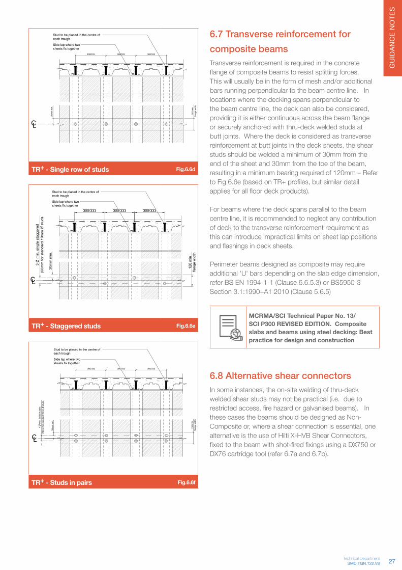
TR+ - Single row of studs Fig.6.6d
SMD.DOD.180.V2
Stud to be placed in the centre of each trough
Side lap where twosheets fix together
CL
120
min
flang
e w
idth
300/333 300/333 300/333
3 O
min
. sin
gle
stag
gere
d(6
0mm
for s
tand
ard
19m
m O
stu
ds
30m
m m
in.
TR+ Shear Stud Layout Details, Staggered studs @ butt joint
TR+ - Staggered studs Fig.6.6e
SMD.DOD.181.V2
Stud to be placed in the centre of each trough
Side lap where twosheets fix together
CL
136
min
flang
e w
idth
300/333 300/333 300/333
4 O
min
. stu
ds in
pai
rs(7
6mm
for s
tand
ard
19m
m O
stu
ds
30m
m m
in.
TR+ Shear Stud Layout Details, Studs in pairs @ butt joint
TR+ - Studs in pairs Fig.6.6f
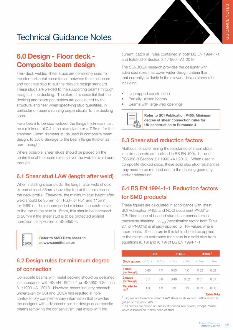
6.7 Transverse reinforcement for composite beamsTransverse reinforcement is required in the concrete flangeofcompositebeamstoresistsplittingforces.This will usually be in the form of mesh and/or additional bars running perpendicular to the beam centre line. In locations where the decking spans perpendicular to thebeamcentreline,thedeckcanalsobeconsidered,providingitiseithercontinuousacrossthebeamflangeor securely anchored with thru-deck welded studs at butt joints. Where the deck is considered as transverse reinforcementatbuttjointsinthedecksheets,theshearstuds should be welded a minimum of 30mm from the endofthesheetand30mmfromthetoeofthebeam,resulting in a minimum bearing required of 120mm – Refer toFig6.6e(basedonTR+profiles,butsimilardetailappliesforallfloordeckproducts).
For beams where the deck spans parallel to the beam centreline,itisrecommendedtoneglectanycontributionof deck to the transverse reinforcement requirement as this can introduce impractical limits on sheet lap positions andflashingsindecksheets.
Perimeter beams designed as composite may require additional'U'barsdependingontheslabedgedimension,refer BS EN 1994-1-1 (Clause 6.6.5.3) or BS5950-3 Section 3.1:1990+A1 2010 (Clause 5.6.5)
MCRMA/SCI Technical Paper No. 13/SCI P300 REVISED EDITION. Composite slabs and beams using steel decking: Best practice for design and construction
6.8 Alternative shear connectorsInsomeinstances,theon-siteweldingofthru-deckwelded shear studs may not be practical (i.e. due to restrictedaccess,firehazardorgalvanisedbeams).Inthese cases the beams should be designed as Non-Compositeor,whereashearconnectionisessential,onealternativeistheuseofHiltiX-HVBShearConnectors,fixedtothebeamwithshot-firedfixingsusingaDX750orDX76cartridgetool(refer6.7aand6.7b).
27SMD.TGN.122.V8Technical Department

GU
IDAN
CE
NO
TES
Hilti X-HVB installation Fig.6.7a
ItshouldbenotedthattheseHiltiX-HVBConnectorsdonot provide the same capacity as welded shear studs and wherethisalternativeconnectorisspecified,thestructuralsteel designer shall advise the quantity and type required for the composite beam design.
For further information on Hilti X-HVB Shear Connectors contact Hilti (UK) Technical Support
Hilti X-HVB Shear Connectors Fig.6.7b
Refer to Hilti Product Literature on X-HVB Shear Connectors for more information
Need Further Guidance? Contact us on +44 (0)1202 718 898 or email our Technical Team on [email protected]
Visit www.smdltd.co.uk to access all the information in this document on our wiki pageTGNOnline
28

GU
IDAN
CE
NO
TES
Technical Guidance Notes
Whenconsideringdecktocircularramps,theorientationoftopflangesandbeamsforbothprimaryandsecondarybeamsmustbeconsideredtoensureeffectivebearingsare provided at all edges. Due to the irregular shapes involvedinsuchramps,theR51profileisrecommendedparticularly when beams are designed compositely to ensureeffectiveconcretearoundthestuds.
Ramped deck on pre studded beams Fig.7.1c
Consideration must be given to safe means of installation when designing such slopes. The decking should span along the slope (not up/down the slope) and an area for landing the decking packs during construction must beprovided.Theconcretedesign,methodofpouringand impact on programme caused by pouring smaller bays/areastoachievetherequiredslope,mustalsobeconsidered.
Engage SMD in such projects at an early stage to enable the model to be reviewed helping to minimise site buildability and installation issues.
7.2 Fixing tool and stud welding gun restrictionsWheredeck,edgetrimorshearstudsaretobeinstalledto beams with obstructions within 570mm of the top of steellevel,itmaynotbepossibletoachievetherequireddetail on site. Consideration must be given to sequence of works and possibly the design of non-composite beams in such locations.
7.0 Design - Floor deck - Considerations7.1 Falls and rampsWhere metal deck is required to be laid to falls or create aramp,thesupportsmustbesimilarlylaidtofallstoenablesheetstobefixedwithadequatebearing–ReferFig. 7.1a. It is possible to install metal deck to horizontal flangeswheretheangleoffallislessthan2.5º,howeverthis will impact on the ability to install thru-deck welded shear studs due to the small gap created between the deckandflange.
Asaresult,itmaybenecessarytodesignthesheetsassinglespaninsuchscenariosandhence,reducingthebeam centres accordingly to avoid temporary propping.
x
Insufficient bearing. Packerrequired to maintain 50mmbearing.
Support and decklaid to fall
Detailing deck on a fall Fig.7.1a
Deck laid to a steep fall Fig.7.1b
29SMD.TGN.122.V8Technical Department

GU
IDAN
CE
NO
TES
Fixing tool dimensions Fig.7.2a
Refer to SMD.DOD.164 - Fixing tool access restrictions and guidanceat www.smdltd.co.uk
Fixing restrictions - stud welding Fig.7.2b
7.3 Concrete encased beamsIn some instances concrete encased perimeter beams maybespecifiedaspartofthefiredesign.Itisrecommendedthatthebeamisencasedtothetopflangeleveloff-site,thereforeenablingthedeckingtobeinstalledtothebeamtopflangeasnormal.
Where it is not possible to carry out the concrete encasementoff-site,thefollowingprocedureispossibleusingR51profile:
• Deckinginstalledtotopflangeofperimeterbeamasnormal.
• The shuttering is then provided by others. This must
be designed by the structural engineer to sustain the weightofthedecking,wetconcreteandconstructionimposed loads to avoid the temporary propping requirement indicated in Fig 7.3a.
• Deckingisthencutbacktothelineoftheshuttering,with temporary propping in place (if required).
• Inthisdetail,thedeckingwillnotcontributetotheshearresistanceofthefinishedslab.Hairpin/tiebarreinforcementinthetroughsofthedeckingprofilewillneedtobedesigned/specifiedbytheengineer.
Concrete encased beam Fig.7.3a
A similar process to that detailed above can be followed where a building or basement has perimeter concrete wallswithcontinuityreinforcementextendingintothefloorslab,providingtheformworkisdesignedtosupporttheweightofthedecking,wetconcreteandconstructionimposed loads to avoid the need for adjacent temporary propping.
7.4 DurabilityAll SMD decks are manufactured from galvanised steel coil to BS EN 10346 with a standard 275g/m2 coating whichequatesto0.02mm(20μm)perface.Althoughthegalvanisingprovidesaprotectivecoating,itdoesweather,albeit at approximately one tenth of the rate of bare steel (depending upon the prevailing conditions).Usefulreferencesonthelifetofirstmaintenance(LTFM)ofgalvanised steel coil include:
• GalvanizersAssociation,“TheEngineersandArchitects Guide: Hot-dip Galvanizing”
• CorusStripProductsUK,“Protectedwithstrength-Solutions in Galvatite hot-dip galvanised steel”
• TheSteelConstructionInstitute,P262-DurabilityofLight Steel Framing in Residential Building: Second Edition
• SCI Advisory Desk Note 247: Use of Composite ConstructioninanAggressiveEnvironment,”NewSteelConstruction,April2010.
30
GU
IDAN
CE
NO
TES
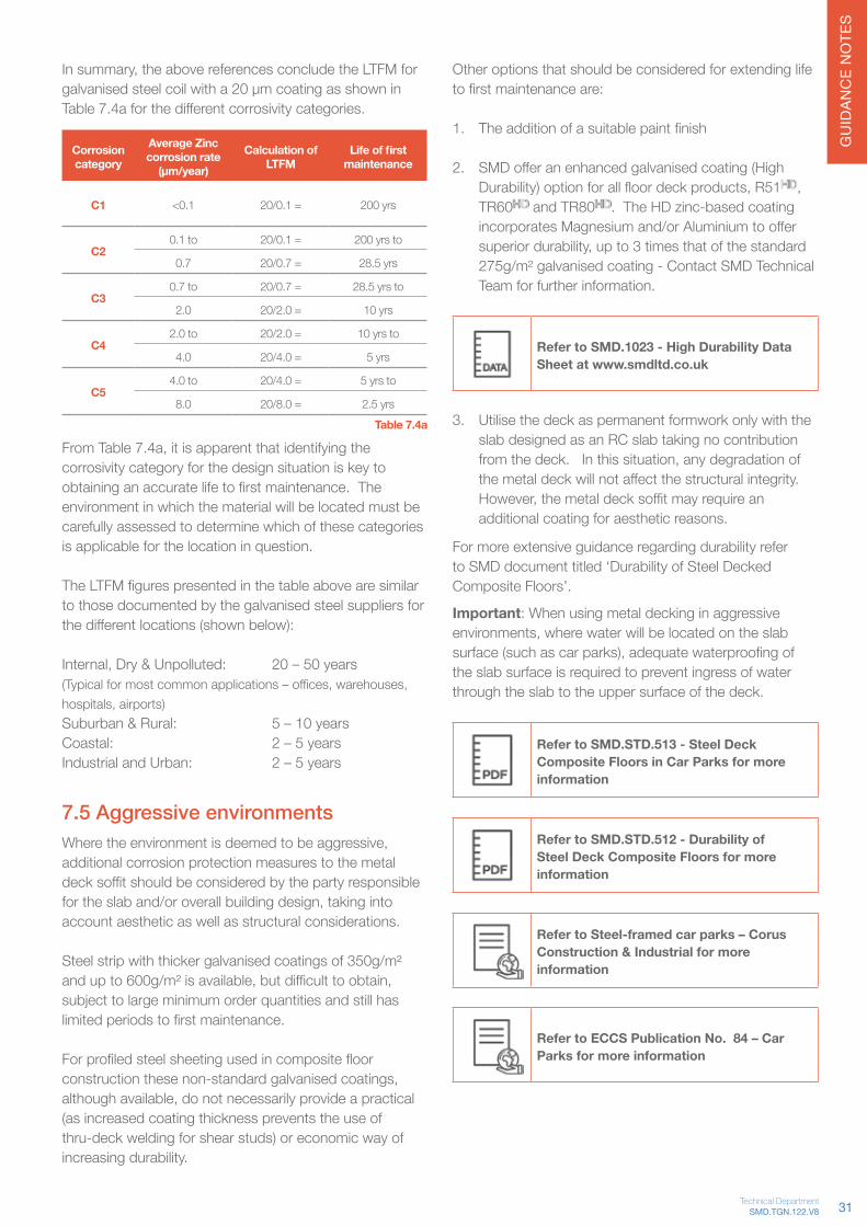
Insummary,theabovereferencesconcludetheLTFMforgalvanisedsteelcoilwitha20μmcoatingasshowninTable7.4aforthedifferentcorrosivitycategories.
Corrosion category
Average Zinc corrosion rate
(μm/year)
Calculation of LTFM
Life of firstmaintenance
C1 <0.1 20/0.1 = 200 yrs
C20.1 to 20/0.1 = 200 yrs to
0.7 20/0.7 = 28.5 yrs
C30.7 to 20/0.7 = 28.5 yrs to
2.0 20/2.0 = 10 yrs
C42.0 to 20/2.0 = 10 yrs to
4.0 20/4.0 = 5 yrs
C54.0 to 20/4.0 = 5 yrs to
8.0 20/8.0 = 2.5 yrsTable 7.4a
FromTable7.4a,itisapparentthatidentifyingthecorrosivity category for the design situation is key to obtaininganaccuratelifetofirstmaintenance.Theenvironment in which the material will be located must be carefully assessed to determine which of these categories is applicable for the location in question.
TheLTFMfigurespresentedinthetableabovearesimilarto those documented by the galvanised steel suppliers for thedifferentlocations(shownbelow):
Internal,Dry&Unpolluted: 20–50years(Typicalformostcommonapplications–offices,warehouses,hospitals,airports)Suburban & Rural: 5 – 10 years Coastal: 2 – 5 years Industrial and Urban: 2 – 5 years
7.5 Aggressive environmentsWheretheenvironmentisdeemedtobeaggressive,additional corrosion protection measures to the metal decksoffitshouldbeconsideredbythepartyresponsiblefortheslaband/oroverallbuildingdesign,takingintoaccount aesthetic as well as structural considerations.
Steel strip with thicker galvanised coatings of 350g/m² andupto600g/m²isavailable,butdifficulttoobtain,subject to large minimum order quantities and still has limitedperiodstofirstmaintenance.
Forprofiledsteelsheetingusedincompositefloorconstructionthesenon-standardgalvanisedcoatings,althoughavailable,donotnecessarilyprovideapractical(as increased coating thickness prevents the use of thru-deck welding for shear studs) or economic way of increasing durability.
Other options that should be considered for extending life tofirstmaintenanceare:
1. Theadditionofasuitablepaintfinish
2. SMDofferanenhancedgalvanisedcoating(HighDurability)optionforallfloordeckproducts,R51HD,TR60HD and TR80HD. The HD zinc-based coating incorporatesMagnesiumand/orAluminiumtooffersuperiordurability,upto3timesthatofthestandard275g/m² galvanised coating - Contact SMD Technical Team for further information.
Refer to SMD.1023 - High Durability Data Sheet at www.smdltd.co.uk
3. Utilise the deck as permanent formwork only with the slab designed as an RC slab taking no contribution fromthedeck.Inthissituation,anydegradationofthemetaldeckwillnotaffectthestructuralintegrity.However,themetaldecksoffitmayrequireanadditional coating for aesthetic reasons.
For more extensive guidance regarding durability refer to SMD document titled ‘Durability of Steel Decked Composite Floors’.
Important: When using metal decking in aggressive environments,wherewaterwillbelocatedontheslabsurface(suchascarparks),adequatewaterproofingofthe slab surface is required to prevent ingress of water through the slab to the upper surface of the deck.
Refer to SMD.STD.513 - Steel Deck Composite Floors in Car Parks for more information
Refer to SMD.STD.512 - Durability of Steel Deck Composite Floors for more information
Refer to Steel-framed car parks – Corus Construction & Industrial for more information
Refer to ECCS Publication No. 84 – Car Parks for more information
31SMD.TGN.122.V8Technical Department

GU
IDAN
CE
NO
TES
7.6 VibrationThe recommended minimum natural frequency for a compositefloorplate(consistingofboththecompositeslabandcompositebeams)is5Hzwhenusedinofficeor domestic type applications. This limit should be increasedto8.4Hzforfloorssubjectedtorhythmicactivitiessuchasgyms,dancestudiosorevenplantareassupporting machinery.
UsingSMDElements®software,thedynamicdeflectionof the composite slab is calculated in accordance with SCI Publication P-354: Design of Floors for Vibration – A New Approach. Using the guidance and calculation method containedinP-354,thisdeflectioncanthenbeaddedto that for the composite beams enabling the Natural Frequencyofthefloorplatetobedetermined.
Refer SCI Publications P076: Design guide on the vibration of floors and P354: Design of floors for vibration – A New Approach
7.7 AcousticsThe acoustic performance of a composite slab is a functionofboththemassoftheslabandthefloorandceilingfinishesapplied.RobustStandardDetailsareavailable to provide performance in accordance with BuildingRegulationsPartEutilisinganumberofdifferentfinishesforboththeceilingandfloor.Thedetailingofsuchfinishesiskeytoprovidetheacousticperformancerequired.
Refer to SCI-P322 Acoustic Performance of Composite Floors for more information
Refer to SCI P-336 Acoustic Detailing of Multi Storey Residential Buildings for more information
Refer to SCI P-372 Acoustic Detailing for Steel Construction for more information
For guidance relating to the acoustic performance of a barecompositeslab,contactSMDTechnicalTeam.Itshouldbenotedthatformoreextensiveguidance,anacoustic specialist may be required.
7.8 Thermal massFollowingastudyatOxfordBrookesUniversity;BRE,The Concrete Centre and CIBS all acknowledge that approximately 100mm is the maximum thickness of concrete that can be mobilised within a typical 24-hour cycle of heating and cooling – refer graph below.
Admittance for NWC and LWC Fig.7.8a
CompositeslabsonR51,TR60+orTR80+intheregionof130mm-150mmthicknessallprovideaneffectiveconcrete volume that meets this 100mm optimum thickness.
Refer www.steelconstruction.info for further information
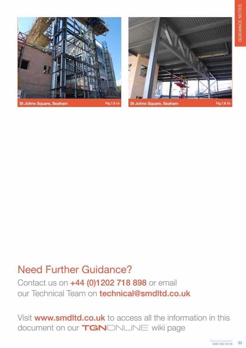
7.8.1 Case Study: St Johns Square, Seaham PartoftheSMDcontractatStJohn’sSquare,SeahamworkingforHambletonSteel,utilisesthethermalmassofthecompositeslabbyexposingtheslabsoffitandproviding natural ventilation through a series of stacks that penetratethemetaldeckandfloorslabs.
ThebuildinghousingaPublicLibrarywithOfficesandaCafé,involvedthedesign,supplyandinstallationof2,700m²ofSMDR51x1.0mmgaugeprofilewithslabthicknesses of 130mm and 160mm.
The building on completion achieved a BREEAM ‘Very Good’ Rating.
Refer www.steelconstruction.info/St_Johns_Square,_Seaham for further information
32
GU
IDAN
CE
NO
TES
St Johns Square, Seaham Fig.7.8.1a St Johns Square, Seaham Fig.7.8.1b
Need Further Guidance? Contact us on +44 (0)1202 718 898 or email our Technical Team on [email protected]
Visit www.smdltd.co.uk to access all the information in this document on our wiki pageTGNOnline
33SMD.TGN.122.V8Technical Department

GU
IDAN
CE
NO
TES
Technical Guidance Notes
8.0 Design - Roof deckSMD structural roof deck products are typically used as the structural deck (tray) for various insulated roof systems including:• Single Ply Membrane• Double skin built-up system• Standing Seam• Green Roofs• Asphalt
Using the Elements®(Roofdeckoption),fullstructuralcalculations can be prepared with a diaphragm design service available upon request.
The use of a structural deck in place of a more traditional linerprovidesbenefitsfromdesignstagerightthroughtoconstruction:
• Inmanyinstances,siteoperativescanwalkdirectlyontheprofilewithouttheneedforcrawlboards
• The longer span nature of structural roof decks results in less secondary members giving an aesthetic unclutteredsoffitwhilstalsosavingtimeduringerection of the frame
AllSMDdeckprofiles,rangingfrom30mmto100mmindepth are designed in accordance with BS EN 1993-1-3,withallproductdesignscomplementedbystructuraltesting carried out at Lucideon.
4-point loading test Fig.8.0a
8.1 QualityThrough the robust Factory Control Procedure (FPC) at ourstateoftheartcomputerisedmanufacturingfacility,allproducts are CE Marked to BS EN 1090-1. The quality management system closely monitors quality of material andgeometrywithQAcertificatesandmaterialcertificatesavailable upon request.
The SMD structural roof deck installation service also comes quality assured with our ISO 9001 accreditation.
Profile Gaugemm
GradeN/mm2
Cover widthmm
Weightkg/m2
Max. Single Span
m
Max. Double Span
m
Canti-levermm
SR30+0.7 350 1000 6.66 1.49 1.77 300
0.9 350 1000 8.57 1.68 1.99 350
SR35+
0.7 350 900 7.58 2.21 2.62 400
0.9 350 900 9.76 2.32 2.75 450
1.2 350 900 13.03 2.67 3.17 550
SR60+
0.7 350 850 7.83 3.15 3.74 700
0.9 350 850 10.08 3.28 3.88 800
1.2 350 850 13.46 3.86 4.58 950
SR100+
0.75 320 825 9.24 4.40 4.50 1000
1.00 320 825 11.91 4.90 5.50 1125
1.25 320 825 15.90 5.30 6.75 1250
SR135
0.75 320 930 9.71 5.30 5.25 1150
1.00 320 930 12.95 5.80 6.50 1275
1.25 320 930 16.13 6.30 7.75 1400
SR153
0.75 320 840 10.75 5.75 6.30 1300
1.00 320 840 14.33 6.50 7.75 1375
1.25 320 840 17.86 7.00 9.00 1450
SR158
0.75 320 750 12.04 6.25 6.75 1250
1.00 320 750 16.05 6.90 8.25 1400
1.25 320 750 20.00 7.45 9.00 1550
SR200
0.75 320 750 12.04 5.25 5.50 1450
1.00 320 750 16.05 8.00 9.25 1650
1.25 320 750 20.00 8.75 10.75 1850
Table 8.1a
NOTE: Numbers shown RED should not be used as sheet lengths exceed recommended maximum for logistic and manual handling reasons.
34
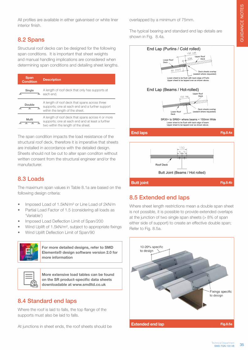
GU
IDAN
CE
NO
TES
Allprofilesareavailableineithergalvanisedorwhitelinerinteriorfinish.
8.2 SpansStructural roof decks can be designed for the following span conditions. It is important that sheet weights and manual handling implications are considered when determining span conditions and detailing sheet lengths.
Span Condition Description
Single A length of roof deck that only has supports at each end.
Double A length of roof deck that spans across three supports; one at each end and a further support within the length of the sheet.
Multi A length of roof deck that spans across 4 or more supports; one at each end and at least a further two within the length of the sheet.
The span condition impacts the load resistance of the structuralroofdeck,thereforeitisimperativethatsheetsare installed in accordance with the detailed design. Sheets should not be cut to alter span conditon without written consent from the structural engineer and/or the manufacturer.
8.3 LoadsThe maximum span values in Table 8.1a are based on the following design criteria:
• Imposed Load of 1.5kN/m² or Line Load of 2kN/m• Partial Load Factor of 1.5 (considering all loads as
‘Variable’)• ImposedLoadDeflectionLimitofSpan/200• WindUpliftof1.5kN/m²,subjecttoappropriatefixings• WindUpliftDeflectionLimitofSpan/90
For more detailed designs, refer to SMD Elements® design software version 2.0 for more information
More extensive load tables can be found on the SR product-specific data sheets downloadable at www.smdltd.co.uk
8.4 Standard end lapsWheretheroofislaidtofalls,thetopflangeofthesupports must also be laid to falls.
Atjunctionsinsheetends,theroofsheetsshouldbe
overlapped by a minimum of 75mm.
The typical bearing and standard end lap details are shown in Fig. 8.4a.
Roof Deck
Butt Joint (Beams / Hot rolled)
End Lap (Beams / Hot-rolled)
End Lap (Purlins / Cold rolled)
Deck sheets overlap(sealant where requested)
Upper RoofDeck
Lower sheet to be flush with back edge of PurlinUpper sheet to be lapped over as shown above.
Lower RoofDeck
SR100+ for all flange sizes and deeper
SR30+ to SR60+ where beams < 150mm WideLower sheet to be flush with back edge of beamUpper sheet to be lapped over as shown above.
Upper RoofDeck
Lower RoofDeck
Deck sheets overlap(sealant where requested)
End laps Fig.8.4a
Roof Deck
Butt Joint (Beams / Hot rolled)
Butt joint Fig.8.4b
8.5 Extended end lapsWhere sheet length restrictions mean a double span sheet isnotpossible,itispossibletoprovideextendedoverlapsat the junction of two single span sheets (> 8% of span eithersideofsupport)tocreateaneffectivedoublespan;Refer to Fig. 8.5a.
Extended end lap Fig.8.5a
35SMD.TGN.122.V8Technical Department
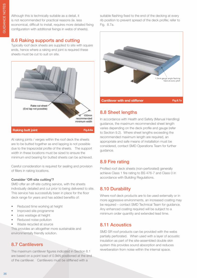
GU
IDAN
CE
NO
TES
Althoughthisistechnicallysuitableasadetail,itis not recommended for practical reasons (ie. less economical,difficulttoinstall,requiresmoredetailedfixingconfigurationwithadditionalfixingsinwebsofsheets).
8.6 Raking supports and cuttingTypically roof deck sheets are supplied to site with square ends,hencewherearakingendjointisrequiredthesesheets must be cut to suit on site.
Raking butt joint Fig.8.6a
At raking joints / verges within the roof deck the sheets are to be butted together as end lapping is not possible duetothetrapezoidalprofileofthesheets.Thesupportwidth in these locations must be sized to ensure the minimum end bearing for butted sheets can be achieved.
Careful consideration is required for sealing and provision offillersinrakinglocations.
Consider ‘Off-site cutting’?SMDofferanoff-sitecuttingservice,withthesheetsindividually detailed and cut prior to being delivered to site. Thisservicehassuccessfullybeeninplaceforthefloordeckrangeforyearsandhasaddedbenefitsof:
• Reduced time working at height• Improved site programme• Less wastage at height• Reduced noise pollution• Waste recycled at sourceThis provides an altogether more sustainable and environmentally friendly solution.
8.7 CantileversThemaximumcantileverfiguresindicatedinSection8.1are based on a point load of 0.9kN positioned at the end ofthecantilever.Cantileversmustbestiffenedwitha
suitableflashingfixedtotheendofthedeckingateveryribpositiontopreventspreadofthedeckprofile;refertoFig. 8.7a.
Cantilever with end stiffener Fig.8.7a
8.8 Sheet lengths In accordance with Health and Safety (Manual Handling) guidance,themaximumrecommendedsheetlengthvariesdependingonthedeckprofileandgauge(referto Section 9.2). Where sheet lengths exceeding the recommendedmaximumlengtharerequired,anappropriate and safe means of installation must be considered,contactSMDOperationsTeamforfurtherguidance.
8.9 Fire ratingProfiledroofdecksheets(non-perforated)generallyachieveClass1fireratingtoBS476-7andClass0inaccordance with Building Regulations.
8.10 DurabilityWhere roof deck products are to be used externally or in moreaggressiveenvironments,anincreasedcoatingmaybe required – contact SMD Technical Team for guidance. Any enhanced coating required will be subject to a minimum order quantity and extended lead time.
8.11 AcousticsSMD SR roof products can be provided with the webs partially perforated. When used with a layer of acoustic insulation as part of the site-assembled double skin system this provides sound absorption and reduces reverberation from noise within the internal space.
36
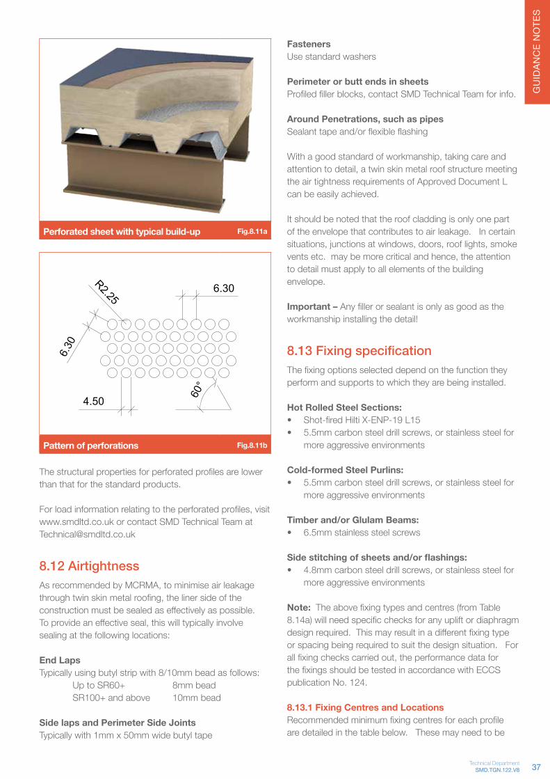
GU
IDAN
CE
NO
TES
Perforated sheet with typical build-up Fig.8.11a
6.30
R2.25
60°
4.50
6.30
Pattern of perforations Fig.8.11b
Thestructuralpropertiesforperforatedprofilesarelowerthan that for the standard products.
Forloadinformationrelatingtotheperforatedprofiles,visitwww.smdltd.co.uk or contact SMD Technical Team at [email protected]
8.12 AirtightnessAsrecommendedbyMCRMA,tominimiseairleakagethroughtwinskinmetalroofing,thelinersideoftheconstructionmustbesealedaseffectivelyaspossible.Toprovideaneffectiveseal,thiswilltypicallyinvolvesealing at the following locations:
End LapsTypically using butyl strip with 8/10mm bead as follows: Up to SR60+ 8mm bead SR100+ and above 10mm bead
Side laps and Perimeter Side JointsTypically with 1mm x 50mm wide butyl tape
Fasteners Use standard washers
Perimeter or butt ends in sheets Profiledfillerblocks,contactSMDTechnicalTeamforinfo.
Around Penetrations, such as pipes Sealanttapeand/orflexibleflashing
Withagoodstandardofworkmanship,takingcareandattentiontodetail,atwinskinmetalroofstructuremeetingthe air tightness requirements of Approved Document L can be easily achieved.
It should be noted that the roof cladding is only one part of the envelope that contributes to air leakage. In certain situations,junctionsatwindows,doors,rooflights,smokeventsetc.maybemorecriticalandhence,theattentionto detail must apply to all elements of the building envelope.
Important – Anyfillerorsealantisonlyasgoodastheworkmanship installing the detail!
8.13 Fixing specification Thefixingoptionsselecteddependonthefunctiontheyperform and supports to which they are being installed.
Hot Rolled Steel Sections:• Shot-firedHiltiX-ENP-19L15• 5.5mmcarbonsteeldrillscrews,orstainlesssteelfor
more aggressive environments
Cold-formed Steel Purlins:• 5.5mmcarbonsteeldrillscrews,orstainlesssteelfor
more aggressive environments
Timber and/or Glulam Beams:• 6.5mm stainless steel screws
Side stitching of sheets and/or flashings:• 4.8mmcarbonsteeldrillscrews,orstainlesssteelfor
more aggressive environments
Note: Theabovefixingtypesandcentres(fromTable8.14a)willneedspecificchecksforanyupliftordiaphragmdesignrequired.Thismayresultinadifferentfixingtypeor spacing being required to suit the design situation. For allfixingcheckscarriedout,theperformancedataforthefixingsshouldbetestedinaccordancewithECCSpublication No. 124.
8.13.1 Fixing Centres and LocationsRecommendedminimumfixingcentresforeachprofileare detailed in the table below. These may need to be
37SMD.TGN.122.V8Technical Department

GU
IDAN
CE
NO
TES
increased in frequency and/or number where wind uplift load or diaphragm roof design is required – contact SMD Technical Team for further information.
Primary Fasteners Secondary Fasteners
Profile Deck Ends IntermediateSupports Side Laps Side
Supports
SR30+ Every Trough Alternate Troughs Not Essential* 450mm centres
SR35+ Every Trough Alternate Troughs Not Essential* 450mm centres
SR60+ Every Trough Every Trough 450mm centres 450mm centres
SR100+ Every Trough Every Trough 450mm centres 450mm centres
SR135 Every Trough Every Trough 450mm centres 450mm centres
SR153 Every Trough Every Trough 450mm centres 450mm centres
SR158 Every Trough Every Trough 450mm centres 450mm centres
SR200 Every Trough Every Trough 450mm centres 450mm centres
Table 8.13a
Fixing configurations Fig.8.13a
Thebelowrestrictionsonfixingpositionwithinthesheetarebasedonfixingtypesdocumentedabove,BSEN1993-1-3 recommendations and Hilti literature in relation tocartridgefiredpins.
Minimum edge/end distance and spacing• Fixing to end of sheet (A): 20mm minimum• Fixing to edge of support (B): 10mm minimum (based
onsteelflanges>7mm)• Distancebetweentwofixings(C):20mmminimum• Fixing to edge of sheet (D): 10mm minimum
Fixing locations within the sheet Fig.8.13b
8.13.2 Exposed soffitWhere the SR sheets are required to provide an exposed soffitathickergaugeshouldbeconsidered,asthinnergauges can be susceptible to marking when subjected to relatively high impact loads during construction.
8.13.3 Flashing detailsDuetothefixedtroughcentresandcoverwidthsofthestructuralroofdecksheets,thereareanumberofflashingsthatmustbeusedtoclosetheprofileoffatperimeter edges and ridges in the roof. The standard detailsincludingflashingsaredetailedbelow:
Setting out point
Underlap / Overlap
Setting out point and typical overlap Fig.8.13c
38

GU
IDAN
CE
NO
TES
Flat plate flashing 'Z' shape flashing
Side support flashing details Fig.8.13d
Fig.8.14d–Flatplateflashing(RED)and'Z'shapedflashing(GREEN) at Side Supports
Change in span direction Fig.8.13e
No Flashing, sheets lap together
<5° slope
Deck parallel to shallow ridge (<5° slope) Fig.8.13f
Flashing across the top ofthe sheets to form the ridge
Flashing to the steel
>5° slope
Deck/flashing parallel to ridge (>5° slope) Fig.8.13g
39SMD.TGN.122.V8Technical Department

GU
IDAN
CE
NO
TES
Flashing to form the ridge
Ridge flashing on purlins Fig.8.13h
Flashing to form the valley
Valley flashing on purlins Fig.8.13i
8.14 Non-fragilityAllSMDshallowroofdeckprofiles(SR30+toSR100+)have been tested in accordance with ACR(M)001:2005 TestforNon-FragilityofProfiledSheetedRoofAssemblies[Third Edition] and achieved Class B – Non-Fragile Assembly.
ACR(M)001:2005 Test for Non-Fragility of Profiled Sheeted Roof Assemblies [Third Edition]
Non-fragility test Fig.8.14a
8.15 Diaphragm designSRstructuralroofdecksprovideacleanunclutteredsoffitfortheroofingsystem.
It is possible to enhance this uncluttered appearance by utilising the structural roof deck as a diaphragm to transfer wind loads from the perimeter walls to internal vertical bracing/walls,thereforereducing,orremovingtheneedfor in-plane roof bracing.
Todesignthedeckasadiaphragm,thefollowingmustbeconsidered:• Implicationsofdecklayout,voidsizes/locationsand
vertical bracing/wall positions.• Line loads applied to the diaphragm perimeter• Fixings to all perimeter edges of roof deck area• Minimum of three vertical bracing/braced wall
locations required
Note: Itisimportanttonotethatfixingtypeandfrequencymay need to be changed to enable diaphragm design -RefertoFig.8.13aforrecommendedstandardfixingconfigurations.
Forusefulguidanceonstressedskindiaphragmdesign,refer to:
ECCS Publication No88: European Recommendations for the Application of Metal Sheeting acting as a Diaphragm
BS 5950-9: Structural use of steelwork in building – Code of practice for stressed skin design
40
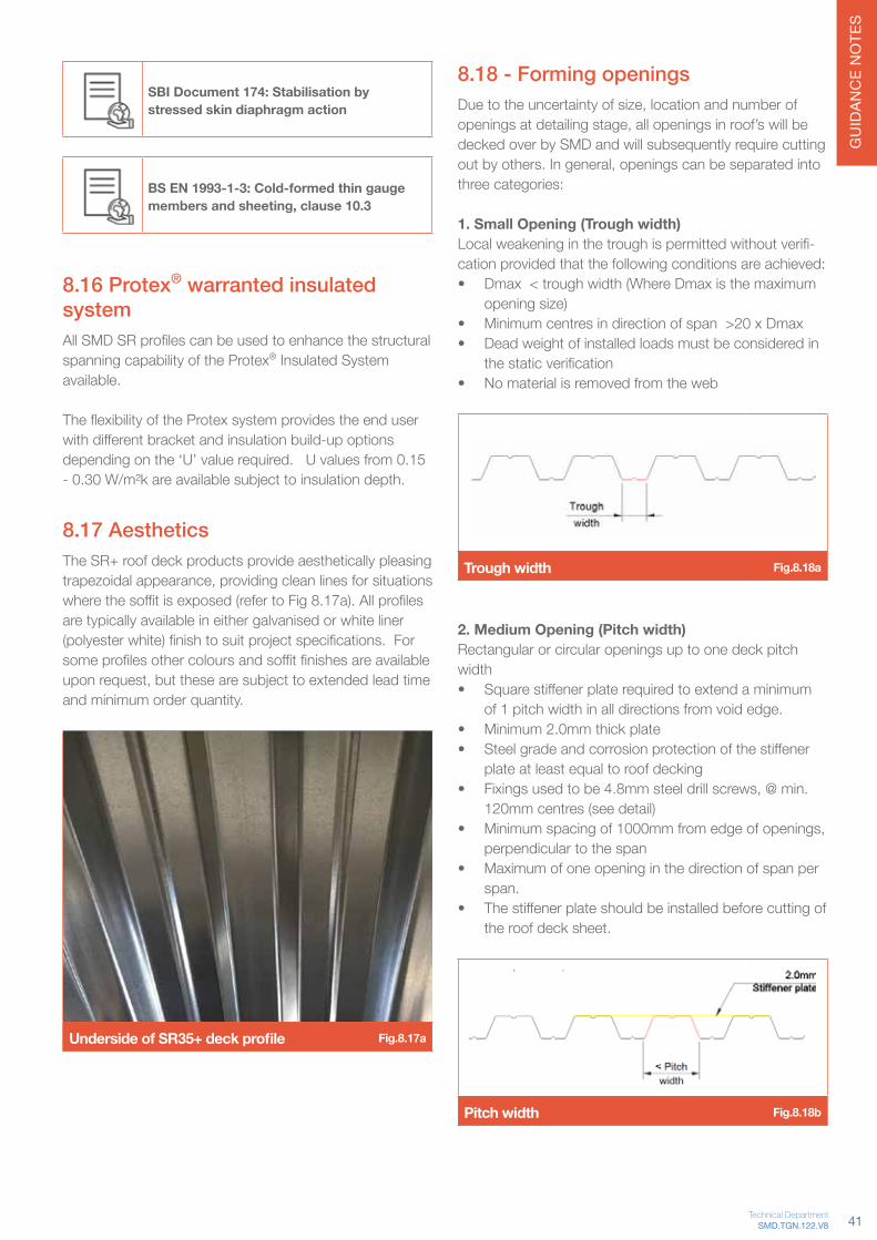
GU
IDAN
CE
NO
TES
SBI Document 174: Stabilisation by stressed skin diaphragm action
BS EN 1993-1-3: Cold-formed thin gauge members and sheeting, clause 10.3
8.16 Protex® warranted insulated systemAllSMDSRprofilescanbeusedtoenhancethestructuralspanning capability of the Protex® Insulated System available.
TheflexibilityoftheProtexsystemprovidestheenduserwithdifferentbracketandinsulationbuild-upoptionsdepending on the ‘U’ value required. U values from 0.15 - 0.30 W/m²k are available subject to insulation depth.
8.17 AestheticsThe SR+ roof deck products provide aesthetically pleasing trapezoidalappearance,providingcleanlinesforsituationswherethesoffitisexposed(refertoFig8.17a).Allprofilesare typically available in either galvanised or white liner (polyesterwhite)finishtosuitprojectspecifications.Forsomeprofilesothercoloursandsoffitfinishesareavailableuponrequest,butthesearesubjecttoextendedleadtimeand minimum order quantity.
Underside of SR35+ deck profile Fig.8.17a
8.18 - Forming openingsDuetotheuncertaintyofsize,locationandnumberofopeningsatdetailingstage,allopeningsinroof’swillbedecked over by SMD and will subsequently require cutting outbyothers.Ingeneral,openingscanbeseparatedintothree categories:
1. Small Opening (Trough width)Localweakeninginthetroughispermittedwithoutverifi-cation provided that the following conditions are achieved:• Dmax < trough width (Where Dmax is the maximum
opening size)• Minimum centres in direction of span >20 x Dmax • Dead weight of installed loads must be considered in
thestaticverification• No material is removed from the web
Trough width Fig.8.18a
2. Medium Opening (Pitch width)Rectangular or circular openings up to one deck pitch width• Squarestiffenerplaterequiredtoextendaminimum
of 1 pitch width in all directions from void edge. • Minimum 2.0mm thick plate• Steelgradeandcorrosionprotectionofthestiffener
plate at least equal to roof decking• Fixingsusedtobe4.8mmsteeldrillscrews,@min.
120mm centres (see detail)• Minimumspacingof1000mmfromedgeofopenings,
perpendicular to the span• Maximum of one opening in the direction of span per
span.• Thestiffenerplateshouldbeinstalledbeforecuttingof
the roof deck sheet.
Pitch width Fig.8.18b
41SMD.TGN.122.V8Technical Department

GU
IDAN
CE
NO
TES
Need Further Guidance? Contact us on +44 (0)1202 718 898 or email our Technical Team on [email protected]
Visit www.smdltd.co.uk to access all the information in this document on our wiki pageTGNOnline
600
600
300
300<
>
<>
120
< e
300<
A A
Section A-A
Void location A on SR60+ Fig.8.18c
600
600
300
300<
>
<>
120
< e
300<
B B
Section B-B
Void location B on SR60+ Fig.8.18d
3. Large Opening (Greater than Pitch width)Foropeningslargerthanpitchwidth,additionalstructuralsupports will be required.
• No restriction on opening length• Thedeckprofileisnotdesignedtocarryloadsfrom
within the opening
Greater than Pitch width Fig.8.18e
These are guidelines only and particular requirements should be checked by the Project Engineer. SMD’s responsibility excludes the design and installation of any additionalstructuralsupports,thestaticverificationofroofdecks with openings and the subsequent cutting of the decksheet.Shouldpointloadsberequired,additionaltrimming steel work will be required. When forming open-ings,considerationneedsbegiventoHealth&Safetyespecially the increased risk of falls from height.
DeckProfile Trough Width(mm)
Deck Pitch(mm)
SR30+ 30 200
SR35+ 43 150
SR60+ 62.5 212.5
SR100+ 38 275
SR135 43 310
SR153 40 280
SR158 41 250
SR200 75 375
Table 8.18a
42

GU
IDAN
CE
NO
TES
Technical Guidance Notes
9.0 Supply of materials9.1 Delivery and accessDecking and edge trim are delivered on 25 tonne capacity articulated vehicles with trailers up to 13.50m long. On supplyandfixcontracts,SMDConstructionManagerwillcontact the client to arrange deliveries to suit minimum product lead times required for delivery of materials. The seven working days stated does not include the day of call offorthedayofdelivery,thisispurelythemanufacturingduration.Wheresiteaccessrestrictionsapply,deliveriescan be arranged on alternative vehicles (i.e. 10 tonne rigid or Hi-Ab); contact SMD Operations Team for further advice.
Deck materials being offloaded on site Fig.9.1a
Uponarrivalatsite,thedriverwillallowamaximumtwohouroffloadingperiod,unlessagreedotherwisewiththeSMDOperationsTeam.Typically,theoffloadingisundertaken by the steelwork contractor in conjunction with the erection of the steel frame. SMD do not undertakeoffloadingofdeliveryvehicles.
9.2 Pack size and sheet length limitsTo prevent damage to the sheets during transport and ensurepacksareofaweightthatiseasilyoffloaded,themaximum and minimum sheet quantities in Table 9.2b apply.
Sheet Length (m)
Profile Gauge mm kg/m2 7.5 8 8.5 9
R51
0.9 12.90 58.1 61.9 65.8 69.7
1.0 14.35 64.6 68.9 73.2 77.5
1.2 17.23 77.5 82.7 87.9 93.0
TR60+
0.9 10.03 75.2 80.2 85.2 90.2
1.0 11.12 83.4 88.9 94.5 100.0
1.2 13.33 100.0 106.6 113.3 120.0
TR80+
0.9 11.33 51.0 54.4 57.8 61.2
1.0 12.54 56.4 60.2 63.9 67.7
1.2 15.06 67.8 72.3 76.8 81.3
SR30+0.7 6.66 50.0 53.3 56.6 59.9
0.9 8.57 64.3 68.6 72.8 77.1
SR35+
0.7 7.40 50.0 53.3 56.6 59.9
0.9 9.52 64.3 68.5 72.8 77.1
1.2 12.72 85.9 91.6 97.3 103.0
SR60+
0.7 7.83 51.1 54.5 57.9 61.4
0.9 10.08 65.9 70.2 74.6 79.0
1.2 13.46 88.0 93.8 99.7 105.6
SR100+
0.75 9.24 56.0 59.7 63.5 67.2
1.00 11.91 74.7 79.7 84.6 89.6
1.25 15.90 93.4 99.6 105.8 112.0
SR135
0.75 9.71 67.7 72.2 76.8 81.3
1.00 12.95 90.3 96.3 102.4 108.4
1.25 16.13 112.5 120.0 127.5 135.0
SR153
0.75 10.75 67.7 72.2 76.8 81.3
1.00 14.33 90.3 96.3 102.3 108.3
1.25 17.86 112.5 120.0 127.5 135.0
SR158
0.75 12.04 67.7 72.2 76.8 81.3
1.00 16.05 90.3 96.3 102.3 108.3
1.25 20.00 112.5 120.0 127.5 135.0
SR200
0.75 12.04 67.7 72.2 76.8 81.3
1.00 16.05 90.3 96.3 102.3 108.3
1.25 20.00 112.5 120.0 127.5 135.0
Table 9.2aRED numbers are not recommended as sheet lengths exceed maximum weight for logistic and manual handling reasons.ORANGE numbers can be used providing pack size and loading-out position consider manual handling distances.
43SMD.TGN.122.V8Technical Department

GU
IDAN
CE
NO
TES
Profile Minimum Sheetsin a Pack
Maximum Sheetsin a Pack
Maximum weight(Tonnes)
R51 6 24 2.0
TR60+ 6 18 2.0
TR80+ 6 15 2.0
SR30+ 10 35 2.0
SR35+ 10 35 2.0
SR60+ 10 30 2.0
SR100+ 10 20 2.0
SR135 10 30 2.0
SR153 10 30 2.0
SR158 10 30 2.0
SR200 10 30 2.0
Table 9.2b
WhereSMDaredetailingaspartofthecontract,sheetlengths are determined on the SMD layout drawing to suit thesupportconfigurationandbuildingfootprint.
The detailed drawings will be designed to provide themosteffectiveuseofthedeckingbyminimisingwaste,reducingtemporaryproppingrequirementsandconsidering Health & Safety concerns related to unloading and manual handling during installation.
Wherepossible,sheetlengthsshouldberestrictedto7.5mforR51,8.0mforTR60+and10.0mforTR80+dueto manual handling restrictions.
For further guidance refer to industry best practice sheet SIG.04, developed in conjunction with HSE.
9.3 Offloading, hoisting and storageDuringoffloadingandhoisting,careshouldbetakentoavoid damage to the decking sheets caused by excessive pressure from slings or chains.
Deck bundles should NEVER be dropped (in any way) from delivery vehicles.
It is normal for the packs to be loaded directly from the delivery vehicle onto the steel frame.
Whilstloadingpacksontothesteelframe,considerationshould be given to pack positions to avoid overloading.
Where packs of roof deck are to be installed onto cold-rolledpulins,packsshouldbeloadedoutdirectlyabovethe hot-rolled supporting beams.
Packs are to be loaded out to ensure equal bearing is achieved at both ends of packs.
In all instances packs must have a minimum bearing of 50mm onto supports at both ends. Single span packs will have a longer bottom sheet and should be loaded out with a minimum of 100mm bearing.
Correct single span loading-out Fig.9.3a
Decking does not store well for long periods of time when exposed to the elements. When necessary to storedeckpacksatgroundlevelforprolongedperiods,the packs should be seated on timber bearers to avoid directcontactwiththeground,coveredwithawaterproofbreathable membrane to avoid exposure to rain and angled to allow any condensation to drain.
Typically,aprolongedperiodisgreaterthan6-8weeks,but will be dependent on the location particularly in an aggressive environment.
Correct storage at ground level Fig.9.3b
9.4 Pack labels / loading-out locationsWhereSMDaredetailingthedeckinglayouts,deckingbundlesareidentifiedonthedeckGAdrawings.Packsaredeliveredtositewithauniqueidentificationtag(Referto Fig 9.4a) showing a typical pack label with relevant information).
Eachfloordeckpackhasaspraystripedownoneside,this indicates the orientation in which they should be loaded onto the steel frame (for aesthetic reasons roof
44

GU
IDAN
CE
NO
TES
deck packs do not come with this spray paint marking).
The spray line corresponds with the overlap side of the sheetsandmustfacetowardsthesetting-outpoint,asindicated on the relevant SMD deck GA drawing.
Deck pack label Fig.9.4a
Toprovideasitecontrolmeasure,thecolourofthesprayline on the pack indicates the decking gauge:
• Green 0.9mm gauge • Blue 1.0mm gauge • Red 1.2mm gauge
Need Further Guidance? Contact us on +44 (0)1202 718 898 or email our Technical Team on [email protected]
Visit www.smdltd.co.uk to access all the information in this document on our wiki pageTGNOnline
The loading out positions for deck packs is clearly detailed on SMD deck GA drawings. It is essential that all packs are loaded out in the correct position and orientation to control Health and Safety issues and minimise the manual handling required.
Refer to SMD Data sheet 04 for more information
For further guidance refer to industry best practice sheet SIG.03, developed in conjunction with HSE.
45SMD.TGN.122.V8Technical Department

GU
IDAN
CE
NO
TES
Technical Guidance Notes
requiredbytheoperative.Wherethissystemisproposed,a thorough assessment should be carried out to consider aPassiveandCollectivemethod,ifpossible,inplaceofthe active protection.
Refer to BCSA Code of Practice for Metal Decking and Stud Welding for more information
Insomeinstances,safetynettingwillnotbesuitable,i.e.insufficientstoreyheight(<3m)orinadequateanchorpoints(blockwork).Inthesesituations,thefollowingfallarrest methods can be considered:
Air bagsAir bags are another form of collective passive fall protection that can be used for storey heights of 1.9m - 4.5m. They are predominantly used on blockwork or concrete structures where no suitable anchor points for safety nets are available.
Toinstallthesystem,theAirbagsarelaidoutandconnected together in the area where fall protection is required.TheAirbagsaretheninflatedasonecompletearea to form the fall protection. This method of fall protection is slow and requires careful planning to ensure the area to receive Air bags is 100% clear of obstacles with all openings and windows boarded over.
Air bags Fig.10.0b
Scaffold platform or crash deckAfully-erectedscaffoldorsystemcrashdeckcan
10.0 Installation - Fall arrest systemsSincetheearly2000’s,SMDandtheindustryingeneralhas recognised safety nets as the primary form of collective passive fall protection.
In accordance with the Work at Height Regulations 2005 and given that for metal deck installation 'avoid work at height' and 'use work equipment to prevent falls' is notreasonablypracticable,allcontractsneedtoadopta system of work that 'minimises the distance and consequenceofafall',thiswillincludehandrails,safetynets and suitable access to level.
Priortocommencementofworks,asuitablesystemoffallprotection and safe access must be in place.
There are three principal methods of fall arrest available:
• Safety Netting• Air Bags (also known as Safety Mats or cushions)• Running Lines and Harnesses
The recommended methods of fall arrest to be used are safety netting for steel frame structures and airbags or similarforallothersituations,astheseprovidePassiveand Collective protection.
Methods of fall arrest available Fig.10.0a
The use of running lines and harnesses are not recommended due to the personal nature and action
46

GU
IDAN
CE
NO
TES
concrete core or wall.
Where deck spans are designed such that pre-propping isrequired(temporarypropsinplacepriortoinstallation),adifferentmethodoffallarrestmaybemoreappropriatedue to the logistical issues for net installation and removal caused by the temporary props.
NOTE: Safetynettingmustnotbefixedtosecondarysteelworksuchasscaffoldhandrailsorcladdingrails.
Net pole and claw application Fig.10.1a
Storey heightsSafetynetsareusuallyonlysuitableforfloorheightsinexcessof3m.Thefloorbelowmustbeclearofallpossible obstructions or protrusions. When planning safetynetting,referenceshouldbemadetothedeflectionchart within FASET guidance. As a general rule the storey height in metres should be a minimum of:
2 + (shortest span of the nets in metres)5
Example: For a net with a shortest span of 6m:
2m+(6m/5)=3.2mfloorminimumstoreyheight
Nets installed to area Fig.10.1b
beerectedbelowthedecklevel.Thesearecostly,sterilisetheareabelowthefloorandhaveanimpactonprogramme due to the time to erect and dismantle.
Scaffold platform or crash deck Fig.10.0c
Early planningAlthough safety nets are the primary method of fall arrest used,itisimportanttoconsiderthemostsuitablemethodon a project-by-project basis. Involving SMD Operations Team early in the planning stage can avoid use of an inappropriate method and any associated impact on programme or cost.
10.1 Safety nets
10.1.1 ControlSMDsafetynetstock,inexcessof50,000m²,ismanaged,repaired,maintainedandtestedbyourfullytrained stores teams located at our Logistic Centres in the Midlands (Nottingham) and Scotland (Coatbridge).
In addition to a unique visual ID tag attached to the net,allnetscarryanRFIDtagwhichislinkedtoournetmanagementsoftwareensuringnetlocation,testdateand required maintenance is logged and maintained in a central system. This ensures these safety critical nets are kept to the highest standard and ready for issue to site as required.
10.1.2 Safety net installation
Whenchoosingafallarrestsystem,theuseofnetsmustbe planned; consideration must be given to the following:
Fixing PointsSafety nets are only suitable as a collective passive form offallpreventionwheresuitablefixingpointswithaprovenloadstrengthof6kNareprovided.Typically,thistakestheformofaprimarysteelframeoranchoredfixingsintoa
47SMD.TGN.122.V8Technical Department

GU
IDAN
CE
NO
TES
Installation methodsThere are a number of recognised methods for installing safety nets that are approved by FASET. The preferred method will depend on numerous factors such as storey height,groundcondition,site-specificrulesetc.
The recommended methods are:
Storey heights 3.0 – 4.5mNet pole and claw with the occasional use of ladders
Site Operative using net pole Fig.10.1c
Storey height in excess of 4.5mMEWP or rope access technique.
The use of a MEWP (mobile elevated working platform) is preferable,howeverthereareinstanceswherethismaynot be suitable (ie. where use of a MEWP would mean extendingtheboomthroughmorethanonefloorofsteelwork or poor/restricted access for MEWP’s).
Rope access is a suitable method for safety net installation where storey heights exceed 4.5m and MEWP access is not possible. It should be noted that the Rope access technique is considerably more time consuming and will therefore impact on both programme and cost.
Note: In some circumstances MEWP’s may be required when working below 4.5m. Unless MEWP's have been specificallyrequestedthestandardNetpoleandclawtechnique should be used.
De-rigging nets:Nets can be de-rigged in the same ways in which they arerigged,dependentonthestoreyheightsandthesiterequirements.
Nets must not be de-rigged until the decking sheets are 100%fixedintoplaceandstitchedtogether,orontofloorsthathavehadstudsweldedasthiscreatesmultiplesnagging points once the nets have been lowered.
Safety netting must be de-rigged prior to any welding operations as the weld splatter will burn through and damage nets.
Need Further Guidance? Contact us on +44 (0)1202 718 898 or email our Technical Team on [email protected]
Visit www.smdltd.co.uk to access all the information in this document on our wiki pageTGNOnline
48

GU
IDAN
CE
NO
TES
Technical Guidance Notes
shouldthenbelapped,linedupandfixedintoplaceoncethe adjacent bay has been laid and the troughs of the deckinghavebeenlinedthrough.Duringinstallation,cumulative measurements of across the bay width should betakentoensuretheeffectiveproductcoverwidthisconsistently achieved.
Cutting / notchingDecking sheets are typically delivered to site at the correct square cut length. Where decking ribs sit over beamsthataretoreceiveweldedshearstuds,aroundcolumnsandotherprotrusions,notchingand/orcuttingof the deck will be required. This should be carried out bytrainedoperativesusingsuitabledisccutters(petrol,cordless,electricorpneumatic)withappropriateblade,plasma cutters or similar approved equipment. For somecontracts,cuttingwillbecarriedoutoff-sitepriortodelivery(refertosection13.5),intheseinstancesthesheets will be delivered to site at the correct length and shape for installation with only minor notching required around columns and handrails.
Deck fixingsFixing of the deck and edge trim to the supporting steelwork or walls will typically be carried out using low velocitypowder(‘shot-firing’)orgas-actuatedcartridgetools.Incertaincircumstances,theuseofself-tappingscrews may be necessary.
Refertosection4.6forrecommendedfixingtypesandspacings.
Side lapsAtsidelaps,thedecksheetsmustbestitchedtogetherusingself-tappingscrews,installedwithsuitablescrewguns,atmaximum1.0mcentres.Inadditiontostabilisingthejoint,thesehelpminimisegroutlossexperiencedduring concreting.
Sealing and finishing offGapsupto5mmareacceptableastheyarenotsufficientto allow concrete aggregate to escape.
Note: The decking is not intended to provide a watertight finishandadegreeoffinesandwaterseepage(groutloss)is to be expected from the panel ends and joints.
In areas where it is essential to reduce grout loss to a minimum,theadditionoftapeatallbuttjointsandside
11.0 Installation - Floor Deck and shear studsSMD products should only be installed by those competentandtrainedtodoso.Specificreferenceshould also be given to the BCSA Code of Practice for MetalDeckingandStudWeldingand,asaminimum,thefollowing procedure should be followed.
Pre-startPriortocommencementofdeckinstallation,asystemoffall protection (refer section 10) and safe access must be in place. This should form part of the overall safe system of work agreed by all parties and detailed in the project specificRiskAssessmentandMethodStatement(RAMS).
Weather conditionsDecking bundles should only be opened if all the sheets inthebundlecanbefixedorleftinasafeconditionatthe end of the shift. Consideration must be given during periodsofbadweathertoanyunfixedsheetsasthesemust be secured at the end of each day by using a temporary strap secured to the frame or decking.
Supporting structureWheresupportsaretoreceiveshearstuds,topflangesmust be unpainted and free from grease or rust that might adverselyaffecttheweld.RefertoFixingssection(page24) for guidance on minimum bearings.
Access to levelWhereverpossible,thedeckinginstallationshouldbeplanned to commence from the corner of a building or phase,sothatthenumberofleadingedgesarelimited.The recommended means of access to and egress from the workface should be either temporary Haki type stair or permanentfixedstairwithhandrail.
Refer to SMD Data sheet 18 at www.smdltd.co.uk
Laying decking sheetsUsingtheaccessprovided,theinstallershouldstraddlethefirstbundleofdeckingtoremovethebanding.Thefirstdeckingsheetwillthenbepushedoutontothesteelwork to be used as a working platform from which to lay the remaining sheets in that bay. Decking sheets
49SMD.TGN.122.V8Technical Department
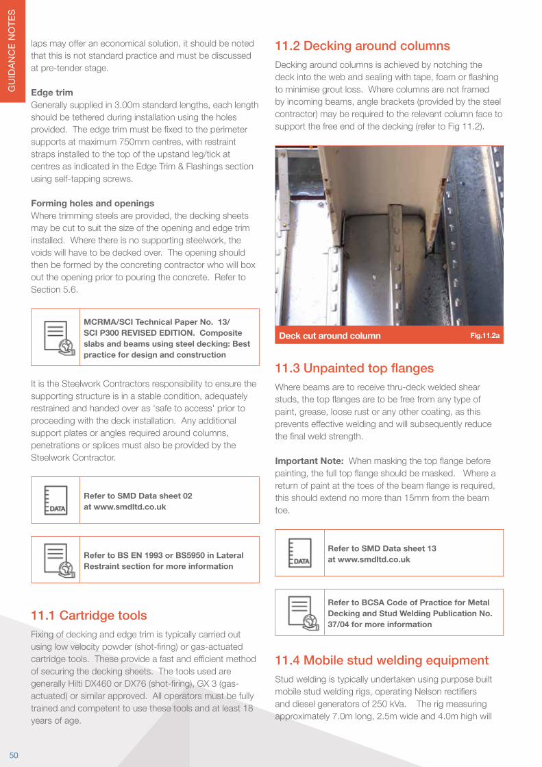
GU
IDAN
CE
NO
TES
lapsmayofferaneconomicalsolution,itshouldbenotedthat this is not standard practice and must be discussed at pre-tender stage.
Edge trimGenerallysuppliedin3.00mstandardlengths,eachlengthshould be tethered during installation using the holes provided.Theedgetrimmustbefixedtotheperimetersupportsatmaximum750mmcentres,withrestraintstraps installed to the top of the upstand leg/tick at centres as indicated in the Edge Trim & Flashings section using self-tapping screws.
Forming holes and openingsWheretrimmingsteelsareprovided,thedeckingsheetsmay be cut to suit the size of the opening and edge trim installed.Wherethereisnosupportingsteelwork,thevoids will have to be decked over. The opening should then be formed by the concreting contractor who will box out the opening prior to pouring the concrete. Refer to Section 5.6.
MCRMA/SCI Technical Paper No. 13/SCI P300 REVISED EDITION. Composite slabs and beams using steel decking: Best practice for design and construction
It is the Steelwork Contractors responsibility to ensure the supportingstructureisinastablecondition,adequatelyrestrained and handed over as 'safe to access' prior to proceeding with the deck installation. Any additional supportplatesoranglesrequiredaroundcolumns,penetrations or splices must also be provided by the Steelwork Contractor.
Refer to SMD Data sheet 02 at www.smdltd.co.uk
Refer to BS EN 1993 or BS5950 in Lateral Restraint section for more information
11.1 Cartridge toolsFixing of decking and edge trim is typically carried out usinglowvelocitypowder(shot-firing)orgas-actuatedcartridgetools.Theseprovideafastandefficientmethodof securing the decking sheets. The tools used are generallyHiltiDX460orDX76(shot-firing),GX3(gas-actuated) or similar approved. All operators must be fully trained and competent to use these tools and at least 18 years of age.
11.2 Decking around columnsDecking around columns is achieved by notching the deckintothewebandsealingwithtape,foamorflashingto minimise grout loss. Where columns are not framed byincomingbeams,anglebrackets(providedbythesteelcontractor) may be required to the relevant column face to support the free end of the decking (refer to Fig 11.2).
Deck cut around column Fig.11.2a
11.3 Unpainted top flangesWhere beams are to receive thru-deck welded shear studs,thetopflangesaretobefreefromanytypeofpaint,grease,looserustoranyothercoating,asthispreventseffectiveweldingandwillsubsequentlyreducethefinalweldstrength.
Important Note: Whenmaskingthetopflangebeforepainting,thefulltopflangeshouldbemasked.Whereareturnofpaintatthetoesofthebeamflangeisrequired,this should extend no more than 15mm from the beam toe.
Refer to SMD Data sheet 13 at www.smdltd.co.uk
Refer to BCSA Code of Practice for Metal Decking and Stud Welding Publication No. 37/04 for more information
11.4 Mobile stud welding equipmentStud welding is typically undertaken using purpose built mobilestudweldingrigs,operatingNelsonrectifiersand diesel generators of 250 kVa. The rig measuring approximately7.0mlong,2.5mwideand4.0mhighwill
50
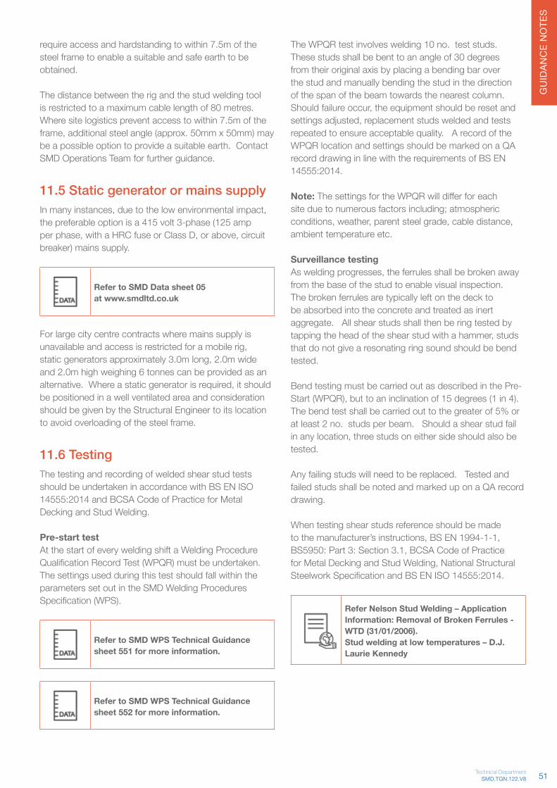
GU
IDAN
CE
NO
TES
require access and hardstanding to within 7.5m of the steel frame to enable a suitable and safe earth to be obtained.
The distance between the rig and the stud welding tool is restricted to a maximum cable length of 80 metres. Where site logistics prevent access to within 7.5m of the frame,additionalsteelangle(approx.50mmx50mm)maybe a possible option to provide a suitable earth. Contact SMD Operations Team for further guidance.
11.5 Static generator or mains supplyInmanyinstances,duetothelowenvironmentalimpact,the preferable option is a 415 volt 3-phase (125 amp perphase,withaHRCfuseorClassD,orabove,circuitbreaker) mains supply.
Refer to SMD Data sheet 05 at www.smdltd.co.uk
For large city centre contracts where mains supply is unavailableandaccessisrestrictedforamobilerig,staticgeneratorsapproximately3.0mlong,2.0mwideand 2.0m high weighing 6 tonnes can be provided as an alternative.Whereastaticgeneratorisrequired,itshouldbe positioned in a well ventilated area and consideration should be given by the Structural Engineer to its location to avoid overloading of the steel frame.
11.6 TestingThe testing and recording of welded shear stud tests should be undertaken in accordance with BS EN ISO 14555:2014 and BCSA Code of Practice for Metal Decking and Stud Welding.
Pre-start testAt the start of every welding shift a Welding Procedure QualificationRecordTest(WPQR)mustbeundertaken.The settings used during this test should fall within the parameters set out in the SMD Welding Procedures Specification(WPS).
Refer to SMD WPS Technical Guidance sheet 551 for more information.
Refer to SMD WPS Technical Guidance sheet 552 for more information.
The WPQR test involves welding 10 no. test studs. These studs shall be bent to an angle of 30 degrees from their original axis by placing a bending bar over the stud and manually bending the stud in the direction of the span of the beam towards the nearest column. Shouldfailureoccur,theequipmentshouldberesetandsettingsadjusted,replacementstudsweldedandtestsrepeated to ensure acceptable quality. A record of the WPQR location and settings should be marked on a QA record drawing in line with the requirements of BS EN 14555:2014. Note: ThesettingsfortheWPQRwilldifferforeachsite due to numerous factors including; atmospheric conditions,weather,parentsteelgrade,cabledistance,ambient temperature etc.
Surveillance testingAsweldingprogresses,theferrulesshallbebrokenawayfrom the base of the stud to enable visual inspection. The broken ferrules are typically left on the deck to be absorbed into the concrete and treated as inert aggregate. All shear studs shall then be ring tested by tappingtheheadoftheshearstudwithahammer,studsthat do not give a resonating ring sound should be bend tested.
Bend testing must be carried out as described in the Pre-Start(WPQR),buttoaninclinationof15degrees(1in4).The bend test shall be carried out to the greater of 5% or at least 2 no. studs per beam. Should a shear stud fail inanylocation,threestudsoneithersideshouldalsobetested.
Any failing studs will need to be replaced. Tested and failed studs shall be noted and marked up on a QA record drawing.
When testing shear studs reference should be made tothemanufacturer’sinstructions,BSEN1994-1-1,BS5950:Part3:Section3.1,BCSACodeofPracticeforMetalDeckingandStudWelding,NationalStructuralSteelworkSpecificationandBSENISO14555:2014.
Refer Nelson Stud Welding – Application Information: Removal of Broken Ferrules - WTD (31/01/2006).Stud welding at low temperatures – D.J. Laurie Kennedy
51SMD.TGN.122.V8Technical Department

GU
IDAN
CE
NO
TES
11.7 Scorching of beamsA huge amount of heat is generated by the welding process with temperatures in excess of 1400 °C.Paintonundersideofflanges<12mmthickwillinevitablyexhibit scorching to some extent in the area immediately below each stud location – Refer image 11.7a
Scorched beams Fig.11.7a
Forbeams>12mmthick,scorchingmaystillbeevidentalthoughitwillbelessprolificasbeamflangethicknessincreases.
Dependentonprojectspecification,touch-uporrepairof the area may be required. This should be undertaken by the contractor responsible for the paint coating of the steelframe.Whereintumescentpaintisappliedoff-site,thismayexpandlocallybeloweachstudlocation.
Itisgenerallyacceptedthat,providedthesurfaceofthefinishremainsintact,noremedialactionisrequiredsubject to the paint manufacturers approval and project specification.
11.8 Minimising grout lossDeck sheets are designed to butt join with the ribs of the profilelinedthroughtoavoidgapsandminimisegroutloss.
Metal deck is not intended to provide a watertight solution,thereforesmallquantitiesofgroutandwaterlossare inevitable. Gaps in excess of 5mm should be sealed usingeithertapeorexpandingfoam.Generally,gapslessthan 5mm are acceptable with no special provision as theyaretoosmalltoallowaggregatetoescape,althoughgrout loss will occur.
Ifthesoffitandtrimisintendedtobefullyexposedinitsfinalcondition,considerationshouldbegiveattenderstage to the taping of all joints prior to concreting or alternatively jet-washing the underside of steelwork post concrete pour.
The use of needle head vibrating pokers is not recommended as these can encourage greater grout loss.Contact SMD Concrete Team for further information.
Refer to SMD Data sheet 24 for more information
Need Further Guidance? Contact us on +44 (0)1202 718 898 or email our Technical Team on [email protected]
Visit www.smdltd.co.uk to access all the information in this document on our wiki pageTGNOnline
52

GU
IDAN
CE
NO
TES
Technical Guidance Notes
Loading platforms Where loading out plant and materials directly to the workingareaisnotpossible,loadingplatform/sshouldbe provided. These should be safe and adequately sized topermitthestorageofplant,materialsandenablesitepersonnel to access from all sides.
Ground conditions Suitable hard standing areas are required to accommodateallconstructiontrafficloadsassociatedwiththeconcreteworks,includingconcretepumpandtrucks.
Access / egress facilities Safemeansofaccessandegressmustbeprovided,positionedtosuitthestartandfinishlocationsofeachpourarea.Specificconsiderationshouldbegiventothisitemwhenpowerfloatoperationsaretobecarriedout.
Site protection Adequate protection from on-site activities must be providedtoalladjoiningproperties/premises,includingitemscontainedwithinitsboundaries.Thisisnotspecificto the concrete works and should typically be considered by a Main Contractor at planning stage. Where there are completed works in close proximity to the concrete pour area,adequateprotectionmustalsobeprovidedtoavoiddamage.
Site protection screening Fig.12.1b
Other trades Adequate protection and/or segregation areas must be provided for other trades working in the vicinity of the concrete works.
12.0 Concrete12.1 Site ConsiderationsBuilding envelopeToenableanacceptablesurfacefinishtobeachieved,wherepossible,concretepoursshouldbecarriedoutinan enclosed environment to provide adequate protection of the works from prevailing weather conditions (including wind,surfacewater,frost,drivingrainandexcessheatfrom the sun). Ambient temperatures must be suitable forconcreteplacingandfinishingoperations.Insomeinstances this may require provision of heaters and/or insulation material to the top and underside of the slab. It is appreciated that this is not always feasible due to site programme and logistics etc. A Project Team must also understand that the lack of a weatherproof building envelopecouldhaveadetrimentaleffect(dependentonseverityoftheconditions)onthefinalsurfacefinishachievableandthisisbeyondthecontrolofaflooringcontractor.
Wash-out facilityAdequate wash-out facilities for the disposal of surplus concrete material from both the pump and trucks should beprovided,i.e.designatedareainthegroundand/orpolythenelinedskips,includingawatersupplyforcleaning of plant and equipment.
Pump hopper discharge Fig.12.1a
Lifting to levelA means (crane/telehandler) for lifting plant and materials to level is required to enable works to commence.
53SMD.TGN.122.V8Technical Department
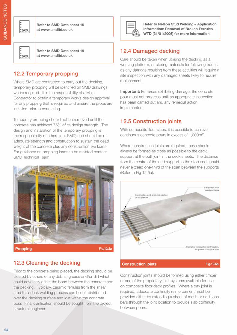
GU
IDAN
CE
NO
TES
Refer to SMD Data sheet 15 at www.smdltd.co.uk
Refer to SMD Data sheet 19 at www.smdltd.co.uk
12.2 Temporary proppingWhereSMDarecontractedtocarryoutthedecking,temporaryproppingwillbeidentifiedonSMDdrawings,where required. It is the responsibility of a Main Contractor to obtain a temporary works design approval for any propping that is required and ensure the props are installed prior to concreting. Temporary propping should not be removed until the concrete has achieved 75% of its design strength. The design and installation of the temporary propping is the responsibility of others (not SMD) and should be of adequate strength and construction to sustain the dead weight of the concrete plus any construction live loads. For guidance on propping loads to be resisted contact SMD Technical Team.
Propping Fig.12.2a
12.3 Cleaning the deckingPriortotheconcretebeingplaced,thedeckingshouldbeclearedbyothersofanydebris,greaseand/ordirtwhichcouldadverselyaffectthebondbetweentheconcreteandthedecking.Typically,ceramicferrulesfromtheshearstud thru-deck welding process can be left distributed over the decking surface and lost within the concrete pour.Finalclarificationshouldbesoughtfromtheprojectstructural engineer
Refer to Nelson Stud Welding – Application Information: Removal of Broken Ferrules - WTD (31/01/2006) for more information
12.4 Damaged deckingCare should be taken when utilising the decking as a workingplatform,orstoringmaterialsforfollowingtrades,as any damage resulting from these activities will require a site inspection with any damaged sheets likely to require replacement.
Important:Forareasexhibitingdamage,theconcretepour must not progress until an appropriate inspection has been carried out and any remedial action implemented.
12.5 Construction jointsWithcompositefloorslabs,itispossibletoachievecontinuousconcretepoursinexcessof1,000m2.
Whereconstructionjointsarerequired,theseshouldalways be formed as close as possible to the deck support at the butt joint in the deck sheets. The distance from the centre of the end support to the stop end should never exceed one-third of the span between the supports (Refer to Fig 12.5a).
Construction joints Fig.12.5a
Construction joints should be formed using either timber or one of the proprietary joint systems available for use oncompositefloordeckprofiles.Whereadayjointisrequired,adequatecontinuityreinforcementmustbeprovided either by extending a sheet of mesh or additional bars through the joint location to provide slab continuity between pours.
54
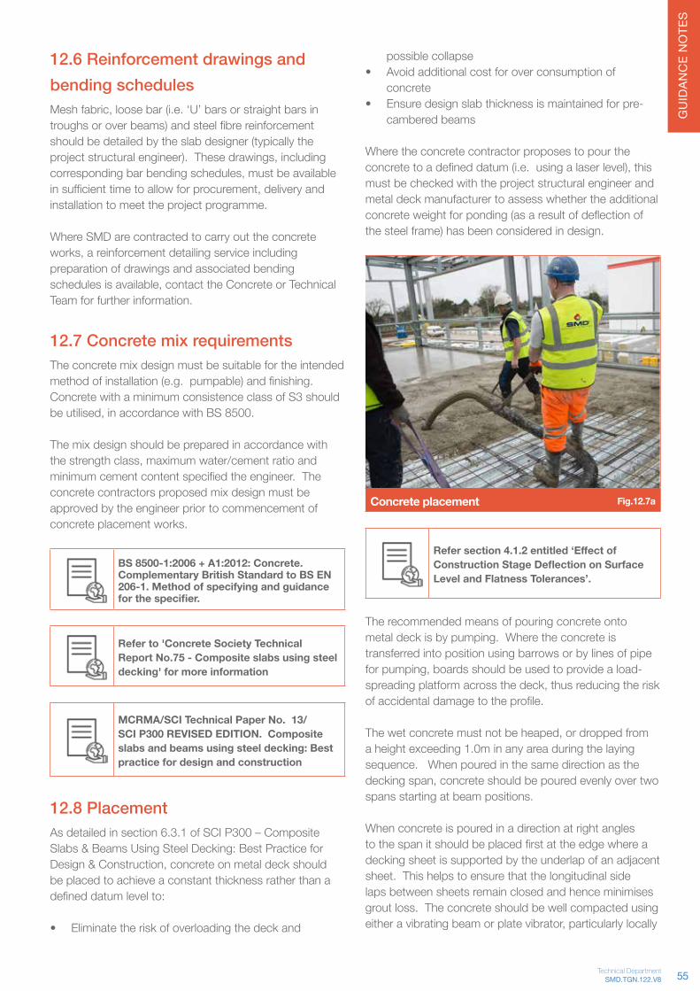
GU
IDAN
CE
NO
TES
12.6 Reinforcement drawings and bending schedulesMeshfabric,loosebar(i.e.‘U’barsorstraightbarsintroughsoroverbeams)andsteelfibrereinforcementshould be detailed by the slab designer (typically the projectstructuralengineer).Thesedrawings,includingcorrespondingbarbendingschedules,mustbeavailableinsufficienttimetoallowforprocurement,deliveryandinstallation to meet the project programme.
Where SMD are contracted to carry out the concrete works,areinforcementdetailingserviceincludingpreparation of drawings and associated bending schedulesisavailable,contacttheConcreteorTechnicalTeam for further information.
12.7 Concrete mix requirementsThe concrete mix design must be suitable for the intended methodofinstallation(e.g.pumpable)andfinishing.Concrete with a minimum consistence class of S3 should beutilised,inaccordancewithBS8500. The mix design should be prepared in accordance with thestrengthclass,maximumwater/cementratioandminimumcementcontentspecifiedtheengineer.Theconcrete contractors proposed mix design must be approved by the engineer prior to commencement of concrete placement works.
BS 8500-1:2006 + A1:2012: Concrete. Complementary British Standard to BS EN 206-1. Method of specifying and guidance for the specifier.
Refer to 'Concrete Society Technical Report No.75 - Composite slabs using steel decking' for more information
MCRMA/SCI Technical Paper No. 13/SCI P300 REVISED EDITION. Composite slabs and beams using steel decking: Best practice for design and construction
12.8 PlacementAs detailed in section 6.3.1 of SCI P300 – Composite Slabs & Beams Using Steel Decking: Best Practice for Design&Construction,concreteonmetaldeckshouldbe placed to achieve a constant thickness rather than a defineddatumlevelto:
• Eliminate the risk of overloading the deck and
possible collapse • Avoid additional cost for over consumption of
concrete • Ensure design slab thickness is maintained for pre-
cambered beams
Where the concrete contractor proposes to pour the concretetoadefineddatum(i.e.usingalaserlevel),thismust be checked with the project structural engineer and metal deck manufacturer to assess whether the additional concreteweightforponding(asaresultofdeflectionofthe steel frame) has been considered in design.
Concrete placement Fig.12.7a
Refer section 4.1.2 entitled ‘Effect of Construction Stage Deflection on Surface Level and Flatness Tolerances’.
The recommended means of pouring concrete onto metal deck is by pumping. Where the concrete is transferred into position using barrows or by lines of pipe forpumping,boardsshouldbeusedtoprovideaload-spreadingplatformacrossthedeck,thusreducingtheriskofaccidentaldamagetotheprofile.
Thewetconcretemustnotbeheaped,ordroppedfroma height exceeding 1.0m in any area during the laying sequence. When poured in the same direction as the deckingspan,concreteshouldbepouredevenlyovertwospans starting at beam positions.
When concrete is poured in a direction at right angles tothespanitshouldbeplacedfirstattheedgewhereadecking sheet is supported by the underlap of an adjacent sheet. This helps to ensure that the longitudinal side laps between sheets remain closed and hence minimises grout loss. The concrete should be well compacted using eitheravibratingbeamorplatevibrator,particularlylocally
55SMD.TGN.122.V8Technical Department
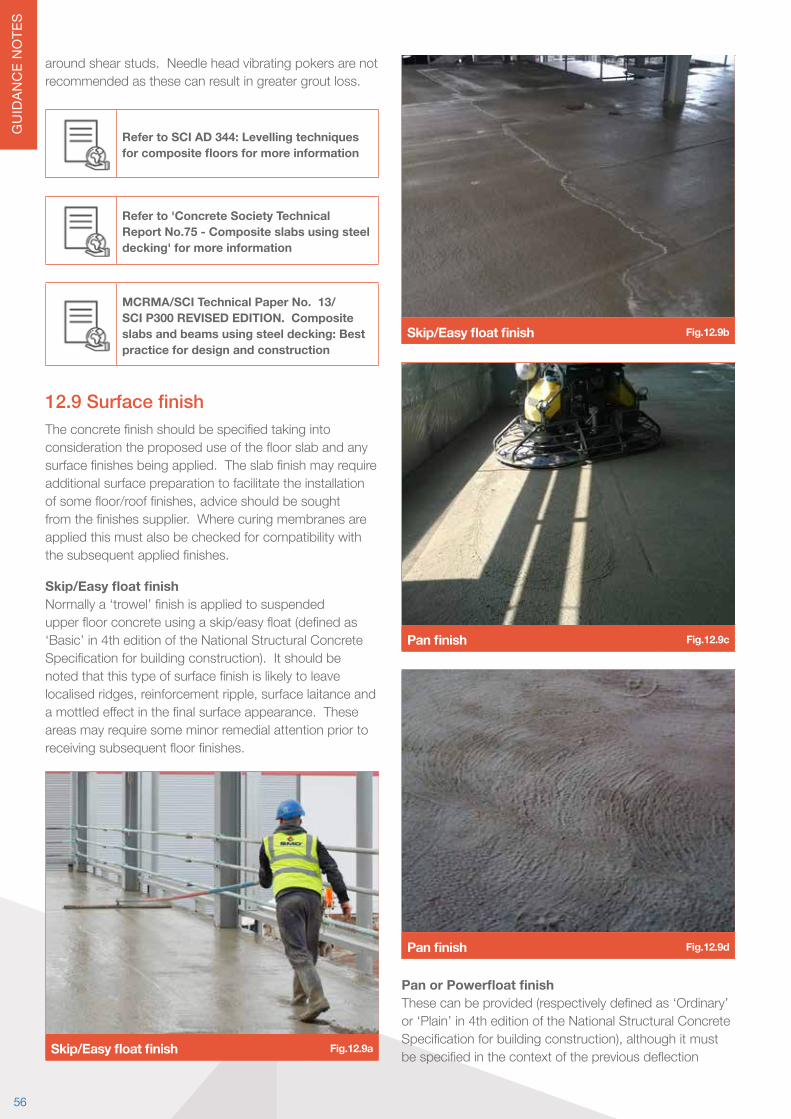
GU
IDAN
CE
NO
TES
around shear studs. Needle head vibrating pokers are not recommended as these can result in greater grout loss.
Refer to SCI AD 344: Levelling techniques for composite floors for more information
Refer to 'Concrete Society Technical Report No.75 - Composite slabs using steel decking' for more information
MCRMA/SCI Technical Paper No. 13/SCI P300 REVISED EDITION. Composite slabs and beams using steel decking: Best practice for design and construction
12.9 Surface finishTheconcretefinishshouldbespecifiedtakingintoconsiderationtheproposeduseofthefloorslabandanysurfacefinishesbeingapplied.Theslabfinishmayrequireadditional surface preparation to facilitate the installation ofsomefloor/rooffinishes,adviceshouldbesoughtfromthefinishessupplier.Wherecuringmembranesareapplied this must also be checked for compatibility with thesubsequentappliedfinishes. Skip/Easy float finishNormallya‘trowel’finishisappliedtosuspendedupperfloorconcreteusingaskip/easyfloat(definedas‘Basic’ in 4th edition of the National Structural Concrete Specificationforbuildingconstruction).Itshouldbenotedthatthistypeofsurfacefinishislikelytoleavelocalisedridges,reinforcementripple,surfacelaitanceandamottledeffectinthefinalsurfaceappearance.Theseareas may require some minor remedial attention prior to receivingsubsequentfloorfinishes.
Skip/Easy float finish Fig.12.9a
Skip/Easy float finish Fig.12.9b
Pan finish Fig.12.9c
Pan finish Fig.12.9d
Pan or Powerfloat finishThesecanbeprovided(respectivelydefinedas‘Ordinary’or ‘Plain’ in 4th edition of the National Structural Concrete Specificationforbuildingconstruction),althoughitmustbespecifiedinthecontextofthepreviousdeflection
56

GU
IDAN
CE
NO
TES
sectioni.e.powerfloatingwillmakethesurfaceappearsmootherandflatter,butnotleveltodatum.Restrictionsonworkinghours,particularlyinbuilt-upareas,maypreventtheoptionofthesetypesoffinishesbeingprovided.
Polished finish Fig.12.9e
Polished finish Fig.12.9f
Refer to 'Concrete Society Technical Report No.75 - Composite slabs using steel decking' for more information
12.10 Surface flatness Surfaceflatnessisthemeasurementofsurfaceregularityovershortdistancestoadefinedplanewhenplaceddirectly in contact with the slab (i.e. a 2m straightedge as documented in BS8204-2). This should not be confused withsurfacelevelrelativetoafixeddatumpoint,refertoFig 12.9c.
Straight Edge Fig.12.10a
Surfaceflatnessdesignations(surfaceregularity)achievable with this type of construction are detailed in Table 12.10a.
BS 8204 Flatness
Designation
Maximum gap (mm) below a 2m straight
edge laid on the surfaceComments
SR1 3(1 in 667)
Not achievable on suspendedfloorsofany
construction
SR2 5(1 in 400)
May be achievable on parts ofacompositefloor,butwillnot be achieved over all of afloor,owingtodeflections.
Thisisatightflatnesstolerance and high levels of workmanship are required
to achieve SR2 on any type ofsuspendedfloor.
SR3 10(1 in 200)
May be achievable over mostofafloor,dependingonthedeflectionsofthe
supporting beams.Table 12.10a
Surface regularity should be measured in accordance with methodology outlined in BS 8204-2 and SCI P300 using a 2m long straightedge placed in direct contact with the concrete surface under its own weight. Deviations of the floorsurfacearethenmeasuredfromtheundersideofthestraightedge,betweentwopointsofcontactwiththefloorsurface,bymeansofaslipgauge/graduatedwedge.
Refer to SMD Data sheet 14 at www.smdltd.co.uk
Where SMD are contracted to carry out the concrete works,surfaceflatnesssurveymeasurementswillbetaken at predetermined grid spacing’s to suit the slab areaandsteelconfigurationsforthecontract.Inareas
57SMD.TGN.122.V8Technical Department
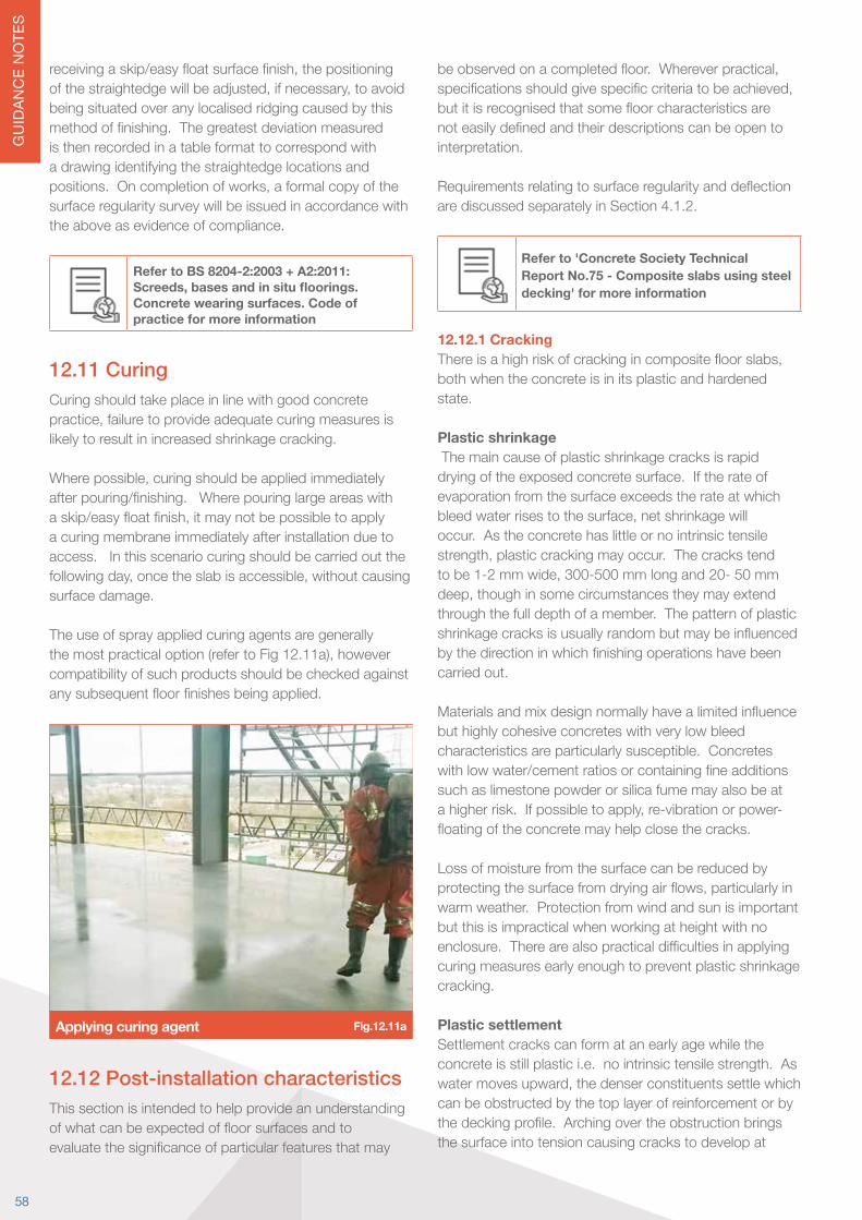
GU
IDAN
CE
NO
TES
receivingaskip/easyfloatsurfacefinish,thepositioningofthestraightedgewillbeadjusted,ifnecessary,toavoidbeing situated over any localised ridging caused by this methodoffinishing.Thegreatestdeviationmeasuredis then recorded in a table format to correspond with a drawing identifying the straightedge locations and positions.Oncompletionofworks,aformalcopyofthesurface regularity survey will be issued in accordance with the above as evidence of compliance.
Refer to BS 8204-2:2003 + A2:2011: Screeds, bases and in situ floorings. Concrete wearing surfaces. Code of practice for more information
12.11 CuringCuring should take place in line with good concrete practice,failuretoprovideadequatecuringmeasuresislikely to result in increased shrinkage cracking.
Wherepossible,curingshouldbeappliedimmediatelyafterpouring/finishing.Wherepouringlargeareaswithaskip/easyfloatfinish,itmaynotbepossibletoapplya curing membrane immediately after installation due to access. In this scenario curing should be carried out the followingday,oncetheslabisaccessible,withoutcausingsurface damage.
The use of spray applied curing agents are generally themostpracticaloption(refertoFig12.11a),howevercompatibility of such products should be checked against anysubsequentfloorfinishesbeingapplied.
Applying curing agent Fig.12.11a
12.12 Post-installation characteristicsThis section is intended to help provide an understanding ofwhatcanbeexpectedoffloorsurfacesandtoevaluatethesignificanceofparticularfeaturesthatmay
beobservedonacompletedfloor.Whereverpractical,specificationsshouldgivespecificcriteriatobeachieved,butitisrecognisedthatsomefloorcharacteristicsarenoteasilydefinedandtheirdescriptionscanbeopentointerpretation. Requirementsrelatingtosurfaceregularityanddeflectionare discussed separately in Section 4.1.2.
Refer to 'Concrete Society Technical Report No.75 - Composite slabs using steel decking' for more information
12.12.1 CrackingThereisahighriskofcrackingincompositefloorslabs,both when the concrete is in its plastic and hardened state. Plastic shrinkage The main cause of plastic shrinkage cracks is rapid drying of the exposed concrete surface. If the rate of evaporation from the surface exceeds the rate at which bleedwaterrisestothesurface,netshrinkagewilloccur. As the concrete has little or no intrinsic tensile strength,plasticcrackingmayoccur.Thecrackstendtobe1-2mmwide,300-500mmlongand20-50mmdeep,thoughinsomecircumstancestheymayextendthrough the full depth of a member. The pattern of plastic shrinkagecracksisusuallyrandombutmaybeinfluencedbythedirectioninwhichfinishingoperationshavebeencarried out. Materialsandmixdesignnormallyhavealimitedinfluencebut highly cohesive concretes with very low bleed characteristics are particularly susceptible. Concretes withlowwater/cementratiosorcontainingfineadditionssuch as limestone powder or silica fume may also be at ahigherrisk.Ifpossibletoapply,re-vibrationorpower-floatingoftheconcretemayhelpclosethecracks. Loss of moisture from the surface can be reduced by protectingthesurfacefromdryingairflows,particularlyinwarm weather. Protection from wind and sun is important but this is impractical when working at height with no enclosure.Therearealsopracticaldifficultiesinapplyingcuring measures early enough to prevent plastic shrinkage cracking. Plastic settlementSettlement cracks can form at an early age while the concrete is still plastic i.e. no intrinsic tensile strength. As watermovesupward,thedenserconstituentssettlewhichcan be obstructed by the top layer of reinforcement or by thedeckingprofile.Archingovertheobstructionbringsthe surface into tension causing cracks to develop at
58
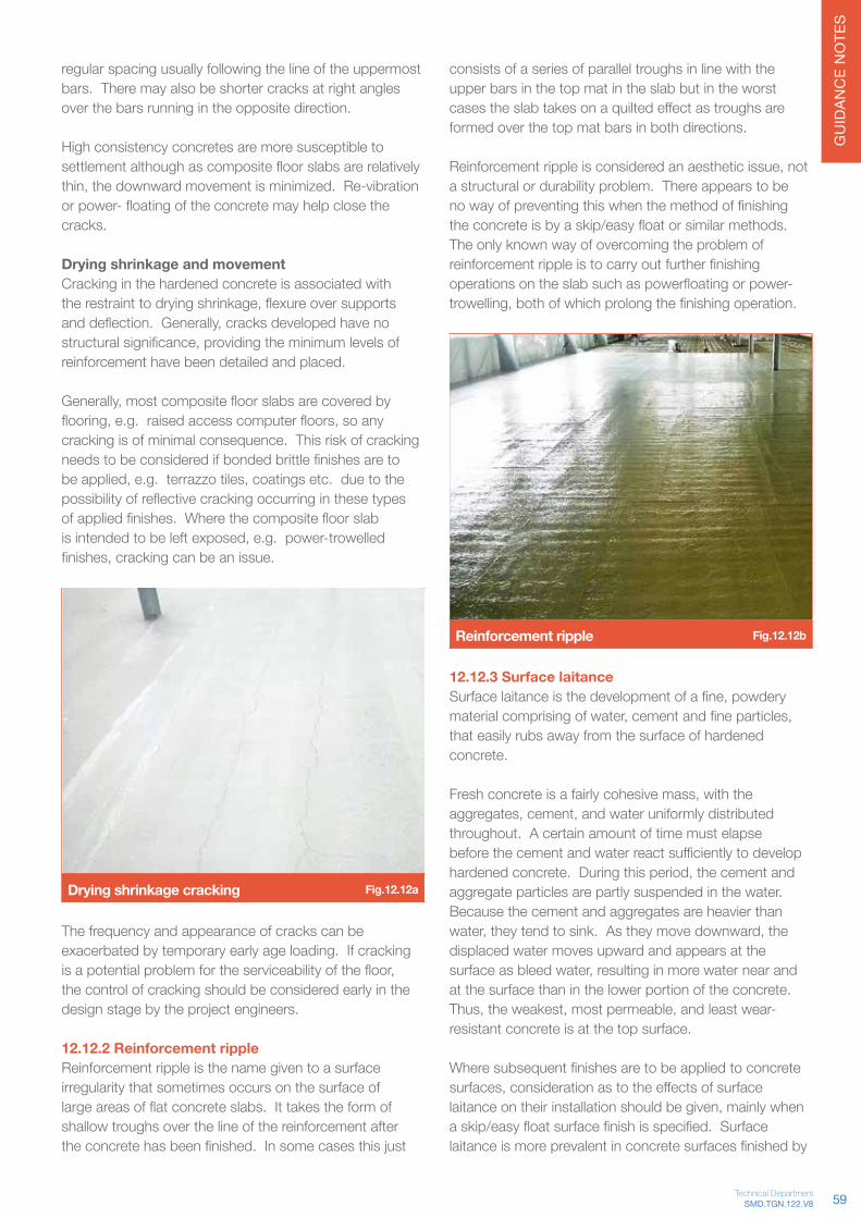
GU
IDAN
CE
NO
TES
regular spacing usually following the line of the uppermost bars. There may also be shorter cracks at right angles over the bars running in the opposite direction. High consistency concretes are more susceptible to settlementalthoughascompositefloorslabsarerelativelythin,thedownwardmovementisminimized.Re-vibrationorpower-floatingoftheconcretemayhelpclosethecracks. Drying shrinkage and movementCracking in the hardened concrete is associated with therestrainttodryingshrinkage,flexureoversupportsanddeflection.Generally,cracksdevelopedhavenostructuralsignificance,providingtheminimumlevelsofreinforcement have been detailed and placed. Generally,mostcompositefloorslabsarecoveredbyflooring,e.g.raisedaccesscomputerfloors,soanycracking is of minimal consequence. This risk of cracking needstobeconsideredifbondedbrittlefinishesaretobeapplied,e.g.terrazzotiles,coatingsetc.duetothepossibilityofreflectivecrackingoccurringinthesetypesofappliedfinishes.Wherethecompositefloorslabisintendedtobeleftexposed,e.g.power-trowelledfinishes,crackingcanbeanissue.
Drying shrinkage cracking Fig.12.12a
The frequency and appearance of cracks can be exacerbated by temporary early age loading. If cracking isapotentialproblemfortheserviceabilityofthefloor,the control of cracking should be considered early in the design stage by the project engineers.
12.12.2 Reinforcement rippleReinforcement ripple is the name given to a surface irregularity that sometimes occurs on the surface of largeareasofflatconcreteslabs.Ittakestheformofshallow troughs over the line of the reinforcement after theconcretehasbeenfinished.Insomecasesthisjust
consists of a series of parallel troughs in line with the upper bars in the top mat in the slab but in the worst casestheslabtakesonaquiltedeffectastroughsareformed over the top mat bars in both directions. Reinforcementrippleisconsideredanaestheticissue,nota structural or durability problem. There appears to be nowayofpreventingthiswhenthemethodoffinishingtheconcreteisbyaskip/easyfloatorsimilarmethods.The only known way of overcoming the problem of reinforcementrippleistocarryoutfurtherfinishingoperationsontheslabsuchaspowerfloatingorpower-trowelling,bothofwhichprolongthefinishingoperation.
Reinforcement ripple Fig.12.12b
12.12.3 Surface laitanceSurfacelaitanceisthedevelopmentofafine,powderymaterialcomprisingofwater,cementandfineparticles,that easily rubs away from the surface of hardened concrete. Freshconcreteisafairlycohesivemass,withtheaggregates,cement,andwateruniformlydistributedthroughout. A certain amount of time must elapse beforethecementandwaterreactsufficientlytodevelophardenedconcrete.Duringthisperiod,thecementandaggregate particles are partly suspended in the water. Because the cement and aggregates are heavier than water,theytendtosink.Astheymovedownward,thedisplaced water moves upward and appears at the surfaceasbleedwater,resultinginmorewaternearandat the surface than in the lower portion of the concrete. Thus,theweakest,mostpermeable,andleastwear-resistant concrete is at the top surface. Wheresubsequentfinishesaretobeappliedtoconcretesurfaces,considerationastotheeffectsofsurfacelaitanceontheirinstallationshouldbegiven,mainlywhenaskip/easyfloatsurfacefinishisspecified.Surfacelaitanceismoreprevalentinconcretesurfacesfinishedby
59SMD.TGN.122.V8Technical Department

GU
IDAN
CE
NO
TES
skip/easyfloatmethodswhererapiddryingofthesurfacecan take place (particularly when concrete placement occurs in exposed environments subject to prevailing weatherconditionsi.e.rainfall,crosswinds,sunlightetc.) as curing is generally applied the following day after placement,duetoaccessrestrictions. Surfacelaitancecanberemovedbygrindingoffthethin/weak friable layer to expose the solid concrete underneath. Another method for consideration would be to apply a surface hardener to improve its wearing ability and reduce dusting of the surface.
12.12.4 DelaminationDelamination is the process whereby a thin (typically 2–4mm) layer becomes detached from the concrete surface. It is primarily caused by the entrapment of air and/or bleed water beneath the surface of the concrete duringfinishingoperations. It is believed that there is a strong link between bleed waterandairwithintheconcrete,astheairusesthefinebleedchannelstoescape.Ifclosingofthesurfacepreventsbleedwaterfromescaping,theaircanaccumulatecausingaweakplaneand,potentially,delamination.
Severalfactorsaffecttheoccurrenceofdelaminationincludingdifferentialsettingofthesurface(theslabconstruction has no walls and the surface is unprotected fromdryingwindandsolargain),aircontent,bleedcharacteristics of the concrete and the application of a dry-shake topping. Delamination is generally only an issue when the concrete is to be the wearing surface. The surface can be reinstated using thin bonded repair mortars.
Delamination Fig.12.12c
Need Further Guidance? Contact us on +44 (0)1202 718 898 or email our Technical Team on [email protected]
Visit www.smdltd.co.uk to access all the information in this document on our wiki pageTGNOnline
60

GU
IDAN
CE
NO
TES
Technical Guidance Notes
HD (Left) and Standard (Right) coating Fig.13.1b
Coating performance in salt spray test Fig.13.1c
Where could HD deck be used? • External locations• Car Parks• Areasidentifiedasaggressiveenvironments(i.e.
category C2-C3 or above)
HD Product SpecificationCoating weight 310 g/m2 (total for both sides)Coatingthickness 25μmpersideStructural steel grade S350 (350 N/mm2)
Composite beamsThru-deck stud welding with HD• Suitability of stud welding tested in accordance with
BS EN ISO 14555.
13.0 Product options13.1 High Durability floor deckWhat is HIGH DURABILITY HD?Our HD products provide the same structural capacity as ourstandardfloordeckrangebutcomewithanenhancedmetalliccoatingwithauniquecompositionofZinc,Aluminium and Magnesium.
Benefits:• Improved corrosion resistance with similar coating
thickness• Suitable for aggressive environments (e.g. chloride
and highly alkaline)• Excellentcut-edgeprotection(selfhealingeffect)
The difference in coating The dense and compact nature of the enhanced metallic coating used on the HD products (refer Fig 13.1a (left image)) provides superior corrosion resistance compared to the more porous structure provided by our standard HotDipGalvanisedZ275coating(referFig13.1a(rightimage)).
HD (Left) and Standard (Right) coating Fig.13.1a
Corrosion behaviour - Salt spray testThe samples in Fig 13.1b and graph (refer Fig 13.1c) show comparison between the two coating options under salt spray test (highly chloride environment) carried out in the lab. Time scales for samples shown in Fig 13.1b are:• HD after 34 weeks• StandardZincafter6weeks
61SMD.TGN.122.V8Technical Department

GU
IDAN
CE
NO
TES
• Weldsettings(WPS)forweldingcurrent,time,protrusion and lift available.
• Un-paintedtopflangesstillrequired(asalways).
Un-painted top flanges not suitable for the environment?Considerpre-studdedbeams(painted)withsinglespan,crushedends,decksheets(refertoSection13.2).
13.2 Crushed ends deck sheetsWhererequired,floordecksheetscanbeprovidedwithcrushed ends. This is the process of closing the end of the sheet ribs by ‘crushing’ the rib to form a slope to the end of the trapezoidal rib (refer to Fig.13.2a).
Crushed ends option is only available with the TR80+ profile.
Crushed ends deck sheets Fig.13.2a
Benefits – Where might it be used?Crushedendsofferanumberofbenefitsspecifictocertain types of construction or detail:
• Quicker to install in single span situations as avoids need for end caps
• Provides a greater concrete section locally to the shearstud,improvingstudperformance
• Enables solid concrete strip over centre of support avoidingneedforacousticand/orfireprofilefillers
• Reduces grout loss on pre-studded projects where deck sheets have to be single span (refer to Fig.13.2b)
• Popular in light gauge frame construction Aswithallproductoptions,crushedendsarenotsuitablein all situations as there are implications on sheet bundling andlayoutconfigurations.ContactSMDTechnicalorOperations teams for further guidance.
Crushed endeddeck sheet
50mm bearing
Pre-studded beam
Crushed ends to pre-studded beam Fig.13.2b
13.3 VoidSafe™ Protection SystemVoidSafe™ is a moulded non-slip composite Glass ReinforcedPlastic(GRP)floorgratingsystem,itisdesigned,suppliedandinstalledbySMDalongwiththemetal deck operations.
The installation of VoidSafe™ eliminates the requirement for void handrail protection systems and temporary void protectionduringconstruction,providingafinalvoidriserprotectionproductwhichminimisesfloorobstructionsduring the process.
Material specification Two main components produce composite GRP: Polyester,resinandglassfibres.Isopthalicpolyesterresin is used to manufacture VoidSafe™ mesh due to its flexibilityandcost.
Properties
Product Nominal Thickness mm
Mesh Open Size(mm)
Panel Weight(kg/m2)
38 12 x 12 24.5
Table 13.3aLoad/Span Table Span (mm) / Load (UDL in kg/m)
Product 250 500 600 750 1000 1200 1500
7,740 6,281 3,225 1,861 785 454 233
Table 13.3bFire resistance • Standard Iso Resin - BS 476 Part 7 Class 2
Typical edge detailThe minimum bearing required for VoidSafe™ is 50mm. Aroundthevoidperimeter,theVoidSafe™issupportedon specially engineered trim manufactured from 2.0mm gauge material with a 40mm recess to provide the VoidSafe™ at the same level as the adjacent slab. Ref Fig 13.3a and 13.3b.
62

GU
IDAN
CE
NO
TES
2D edge section of VoidSafe™ on trim Fig.13.3a
X=114mmminimum,thiswillneedincreasingforshallowslab depths (<150mm).
3D edge section of VoidSafe™ on trim Fig.13.3b
FixingsFixingsmustbeineachcorner,beataminimumof1000mm centres and there should be a minimum of 4 fixingsineachsheet.
Fixing washer options Fig.13.3c
Service penetrationsWhere service penetrations are required in the VoidSafe™ ProtectionSystem,additionaltrimmingsupportmayberequired.Shouldvoidsberequired,adetailedvoidlayoutmust be submitted to enable any additional support requirmentstobespecified.
This information should be made available at design stage,toavoidtheneedforsupporttobeinstalledretrospectively.
Service penetrations with support Fig.13.3d
13.4 Perimeter toeboardIt is recommended and typical for the perimeter toeboard to be provided as part of the edge protection system.However,thereareinstanceswhereitmaybenecessary for the perimeter toeboard to be provided as anadditiontotheperimeteredgetrim.Whererequired,the recommended detail utilises a ‘C’ shaped edge trim withthetoeboardasasecondarytrimfixedtothetopof the ‘C’ shaped edge trim. This has limitations due to theaccessrequiredtofixtheedgetrimtosupportingsteelwork,butiseasiertoremoveuponcompletion.
Perimeter toeboard Fig.13.4a
63SMD.TGN.122.V8Technical Department

GU
IDAN
CE
NO
TES
13.5 Channel edge trimWhere a brickwork or cladding support system is to be integratedintotheslabedge,speciallymanufacturedchannel pourstop can be provided. SMD do not design or manufacture this product but can detail and install as part of the contract – Refer detail 13.5a.
Thereareanumberofdifferentmanufacturersavailable,eachwithslightlydifferentdesignrules.Thestructuraldesignershouldcontactthespecificproductsupplierfordesignguidancerelatingtochannelsizeandspecification.
Channel edge trim Fig.13.5a
13.6 TAB-DeckTM – Fibre concreteDevelopedinpartnershipwithArcelorMittalSheffieldLtd,TAB-Deck™fibrereinforcedconcreteshouldbeinstalled,curedandfinishedinexactlythesamewayasnon-fibrereinforcedconcrete.Theonlyfibrethathasbeenextensively tested for use in TAB-Deck™ projects is ArcelorMittalSheffieldLtdHE1/50steelfibre(refertoFig13.6a) at a dosage of 30kg/m3.
TAB-Deck™ fibre by ArcelorMittal Fig.13.6a
HE 1/50 Technical SpecificationWire dimension 1.0mm (+/- 0.04mm)Fibre Length 50mm (+/- 3mm)Number of Fibres per kg 3100 No Totalfibrelengthper10kg 1575mTensile strength of drawn wire 1100 N/mm2
Rod wire C4D or C7D according to EN 10016-2
Concrete DesignThespecificmixdesignwillalwaysdependonthelocal materials available but should follow these basic guidelines:
• Cement – minimum 350kg/m3 of CEM I or CEM IIIA• Aggregates – maximum 20mm• Fines Content – minimum 450kg/m3 of smaller than
200μincludingcementitiouscontent• Water/CementRatio≤0.50• Minimum Slump – 70mm (before the addition of steel
fibresandsuper-plasticizer)
ArcelorMittalSheffieldLtdcanprovideadviceonindividualmixdesignsandchecksuitabilityforspecificprojects.
MixingThebestmethodforintegratingtheHE1/50steelfibreintothefreshconcreteisbyblastmachines,availableon request from ArcelorMittal Wire Solutions. This is aself-sufficientoperationwherethesteelfibresareblown into the preloaded ready mix truck allowing easy homogenisationofthesteelfibresintotheconcretemix.Alternatively,thesteelfibresmaybeloadedviamobileconveyor belts or placed on the aggregate belt at the ready mix plant.
FinishingWhereapowerfloatfinishisspecifiedwhenusingsteelfibres,considerationshouldbegivenbytheProjectTeamforanapplicationofafibresuppressantdryshaketoppingwhichwouldsignificantlyreducethelikelihoodofexposed/protrudingfibresbecomingapparentinthefinalsurfacefinish.
For further information and design guidance contact ArcelorMittalSheffieldLtdorSMDforacopyoftheTAB-Deck™ design manual.
13.7 Off-Site CuttingWhat is it?Typically metal deck sheets are delivered to site in packs withsquarecutends,tobecuttosuitonsite.TheSMD‘Off-SiteCut’serviceinvolvescuttingthesheetstoexactshape and size required at the factory prior to delivery to site. Any small notches or alterations are then undertaken on-site using a bespoke plasma cutting tool developed for metal deck construction.
The service was developed originally to meet the environmentally sensitive requirement to ‘Reduce Noise’ for deck installation in London. The extent of cutting requireddependsonthecomplexityoftheproject,butthebenefitstheserviceoffers(detailedbelow)havenowseen the service adopted on a number of large city centre contracts.
64

GU
IDAN
CE
NO
TES
Benefits• Reduce noise pollution on site - <70dB at source
compared to 110dB when using petrol driven disc cutters
• Reductioninsitewastageanddifficultyinscrapremoval
• Cutting undertaken in a controlled factory environment• Wastage recycled at source• Reduction in time working at height• Less wastage = Reduction in delivery vehicles
Involve SMD early in the project alongside the Steel Fabricator and Principal Contractor. This enables details to be developed to minimise the impact and cost of the off-sitecuttingrequirement.
When should it be adopted?The‘Off-Site’servicemaynotbenecessaryformanycontracts,butcanbeessentialincertainlocationswhere:• The site is located in a particularly environmentally
sensitive area• Where noise pollution could create a nuisance to
adjacent buildings• Projects with large volumes of decking and where a
highdegreeofsplayed(orraking)cuttingisrequired,to reduce the on-site programme.
Deck design with flashings and SOP Fig.13.7a
Off-Site DesignItisimportanttoinvolveSMDearlyintheprocessfor‘Off-Site’ contracts as there may be design implications or the potentialtodevelopamoreenhanced‘Off-Site’option.Thedesignprocessforoff-sitecuttingdiffersfrom
standard projects; set-out points must consider column sizesandutiliseflashingstominimisetherequirementforsitenotching,furtherlimitinganysitewastage.
The detailing and drawings are modelled in a 3D environment using Tekla; using the fabrication model for this service is a must to ensure sheet sizes provided reflecttheexactframebeingerected.Therefore,sharingof models and utilising BIM principles is an essential part of this service (refer to Fig 13.7b).
Cutting ProcessWithdirectcontroloverthemanufacturingfacility,adesignatedcuttingarea(ReferFig13.7c),specificallytrainedlabour,detailingcutpartdrawingsandadetailedQAprocedureatourfactory,thequalityofour‘off-site’cutting service is assured.
Tekla model of cut sheets Fig.13.7b
Off-site cutting Fig.13.7c
Installation - decking by numbersPacks are delivered to site with the sheets already cut to suit the required size and splay. Packed in a safe manner tominimiseriskduringoffloading(refertoFig.13.7d).
65SMD.TGN.122.V8Technical Department
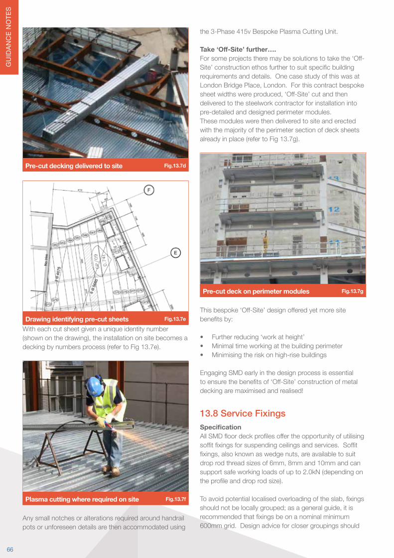
GU
IDAN
CE
NO
TES
Pre-cut decking delivered to site Fig.13.7d
Drawing identifying pre-cut sheets Fig.13.7e
With each cut sheet given a unique identity number (shownonthedrawing),theinstallationonsitebecomesadecking by numbers process (refer to Fig 13.7e).
Plasma cutting where required on site Fig.13.7f
Any small notches or alterations required around handrail pots or unforeseen details are then accommodated using
the 3-Phase 415v Bespoke Plasma Cutting Unit.
Take ‘Off-Site’ further….Forsomeprojectstheremaybesolutionstotakethe‘Off-Site’constructionethosfurthertosuitspecificbuildingrequirements and details. One case study of this was at LondonBridgePlace,London.Forthiscontractbespokesheetwidthswereproduced,‘Off-Site’cutandthendelivered to the steelwork contractor for installation into pre-detailed and designed perimeter modules.These modules were then delivered to site and erected with the majority of the perimeter section of deck sheets already in place (refer to Fig 13.7g).
Pre-cut deck on perimeter modules Fig.13.7g
Thisbespoke‘Off-Site’designofferedyetmoresitebenefitsby:
• Further reducing ‘work at height’• Minimal time working at the building perimeter• Minimising the risk on high-rise buildings
Engaging SMD early in the design process is essential toensurethebenefitsof‘Off-Site’constructionofmetaldecking are maximised and realised!
13.8 Service FixingsSpecificationAllSMDfloordeckprofilesoffertheopportunityofutilisingsoffitfixingsforsuspendingceilingsandservices.Soffitfixings,alsoknownaswedgenuts,areavailabletosuitdroprodthreadsizesof6mm,8mmand10mmandcansupport safe working loads of up to 2.0kN (depending on theprofileanddroprodsize).
Toavoidpotentiallocalisedoverloadingoftheslab,fixingsshouldnotbelocallygrouped;asageneralguide,itisrecommendedthatfixingsbeonanominalminimum600mm grid. Design advice for closer groupings should
66

GU
IDAN
CE
NO
TES
be sought from SMD Technical Team as this will depend onslabdepth,profileandotherdesigncriteriafortheslab.
Note:Soffitfixingsareonlytobeinstalled/loadedaftertheconcreteslabhasgainedspecifieddesignstrength.
R51 'V nut' fixing Fig.13.8a
R51 'V nut' detail Fig.13.8b
TR+ 'Wedge nut' fixing Fig.13.8c
TR+ 'Wedge nut' detail Fig.13.8d
Installation of Service Fixing1. Ensure you have selected the correct wedge nut.2. Thread wedge onto the required rod.3. Insert wedge into the dovetail rib from below and
rotate through 90 degrees so that the sloped face of the wedge bears on the decking rib.
4. The rod should then be tightened by hand up to the roof of the dovetail and a washer/locking plate set againstthesoffitofthedecking.
5. Usemechanicaltighteningtofinishtothetorqueforceinthefixingmanufacturersrecommendations,refertoFig. 13.8b and 13.8d.
AvailabilityWedgenutsforallourfloordeckproductsareavailablefrom Lindapter International Ltd. The wedge nut product namesforourprofilesareasfollows:• R51Profile ‘V’Nut• TR60+ and TR80+ ‘TR60’ Nut
Other Options for Suspended Loads Otherfixingsandproprietaryanchorsarealsoavailable.Theseshouldbeusedinaccordancewithfixingmanufacturersguidance.Theapprovalofsuchfixingsshould be sought from the project structural engineer. Where the load to be suspended exceeds the wedge fixingrecommendation,ensuretheloaddoesnotexceedthe slab design capacity before considering any alternative options. Where bolting through the slab is proposed:• Ensure the use of non-percussive methods to
minimise disturbance of the bond between deck and concrete.
• Position any bolt position through the trough section of the slab with an appropriate spreader plate size to suit the load applied.
• The exact load and position should be checked using SMD Elements® design software.
Foranyqueriesrelatingtoaspecificsoffittypefixing,orload,contacttheSMDTechnicalTeam.
67SMD.TGN.122.V8Technical Department
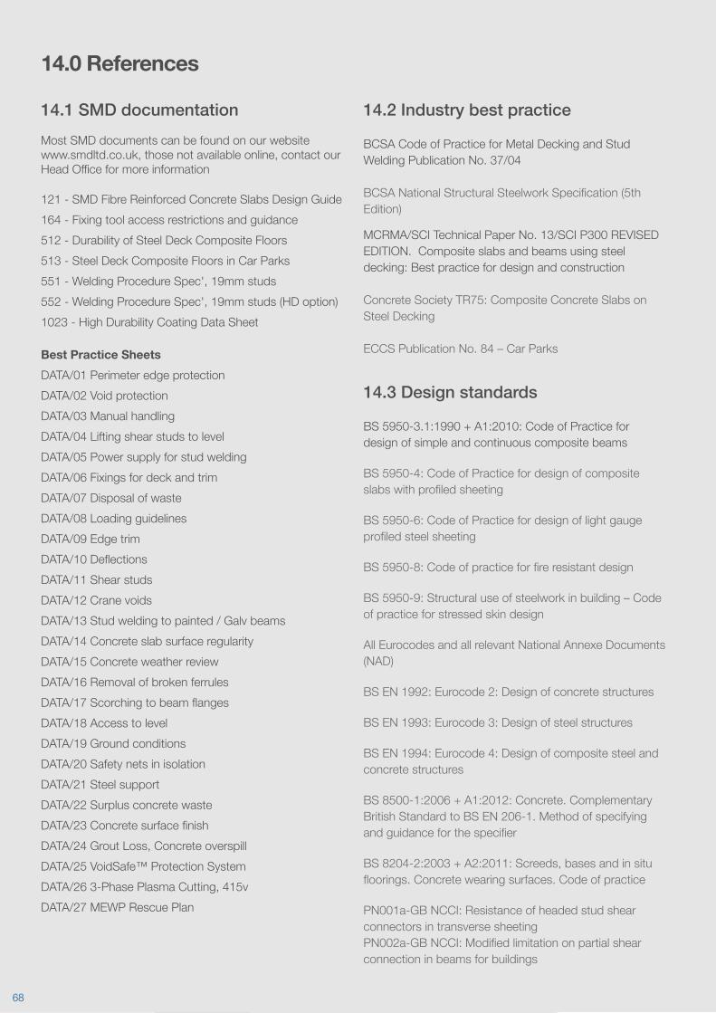
14.0 References
14.1 SMD documentationMost SMD documents can be found on our website www.smdltd.co.uk,thosenotavailableonline,contactourHeadOfficeformoreinformation
121 - SMD Fibre Reinforced Concrete Slabs Design Guide164 - Fixing tool access restrictions and guidance512 - Durability of Steel Deck Composite Floors513 - Steel Deck Composite Floors in Car Parks551-WeldingProcedureSpec',19mmstuds552-WeldingProcedureSpec',19mmstuds(HDoption)1023 - High Durability Coating Data Sheet
Best Practice SheetsDATA/01 Perimeter edge protectionDATA/02 Void protectionDATA/03 Manual handlingDATA/04 Lifting shear studs to levelDATA/05 Power supply for stud weldingDATA/06 Fixings for deck and trimDATA/07 Disposal of wasteDATA/08 Loading guidelinesDATA/09 Edge trimDATA/10DeflectionsDATA/11 Shear studsDATA/12 Crane voidsDATA/13 Stud welding to painted / Galv beamsDATA/14 Concrete slab surface regularityDATA/15 Concrete weather reviewDATA/16 Removal of broken ferrulesDATA/17ScorchingtobeamflangesDATA/18 Access to levelDATA/19 Ground conditionsDATA/20 Safety nets in isolationDATA/21 Steel supportDATA/22 Surplus concrete wasteDATA/23ConcretesurfacefinishDATA/24GroutLoss,ConcreteoverspillDATA/25 VoidSafe™ Protection SystemDATA/263-PhasePlasmaCutting,415vDATA/27 MEWP Rescue Plan
14.2 Industry best practice
BCSA Code of Practice for Metal Decking and Stud Welding Publication No. 37/04
BCSANationalStructuralSteelworkSpecification(5thEdition)
MCRMA/SCI Technical Paper No. 13/SCI P300 REVISED EDITION. Composite slabs and beams using steel decking: Best practice for design and construction
Concrete Society TR75: Composite Concrete Slabs on Steel Decking
ECCS Publication No. 84 – Car Parks
14.3 Design standards
BS 5950-3.1:1990 + A1:2010: Code of Practice for design of simple and continuous composite beams
BS 5950-4: Code of Practice for design of composite slabswithprofiledsheeting
BS 5950-6: Code of Practice for design of light gauge profiledsteelsheeting
BS5950-8:Codeofpracticeforfireresistantdesign
BS 5950-9: Structural use of steelwork in building – Code of practice for stressed skin design
All Eurocodes and all relevant National Annexe Documents (NAD)
BS EN 1992: Eurocode 2: Design of concrete structures
BS EN 1993: Eurocode 3: Design of steel structures
BS EN 1994: Eurocode 4: Design of composite steel and concrete structures
BS 8500-1:2006 + A1:2012: Concrete. Complementary British Standard to BS EN 206-1. Method of specifying andguidanceforthespecifier
BS8204-2:2003+A2:2011:Screeds,basesandinsitufloorings.Concretewearingsurfaces.Codeofpractice
PN001a-GB NCCI: Resistance of headed stud shear connectors in transverse sheetingPN002a-GBNCCI:Modifiedlimitationonpartialshearconnection in beams for buildings
68
PN005c-GB NCCI: Fire resistance design of composite slabs
P-056: (2nd Edition). The Fire Resistance of Composite Floors with Steel Decking
P-076:Designguideonthevibrationoffloors
P-093: Lateral stability of steel beams and columns - common cases of restraint
P-137: Comparative cost of modern commercial buildings
P-285:BenefitsofCompositeFlooring
P-322: Acoustic Performance of Composite Floors
P-331:Designguideonthevibrationoffloors
P-336: Acoustic Detailing of Multi Storey Residential Building
P-354:DesignoffloorsforVibration:ANewApproach
P-359: Composite Design of Steel Framed Buildings
P-372: Acoustic Detailing for Steel Construction
AD 150: Composite Floors: Wheel loads from Forklift Trucks
AD 174: Shear connection along composite edge beams
AD 175: Diaphragm action of steel decking during construction
AD 247: Use of Composite Construction in an aggressive environment
AD 343: Position of reinforcing mesh relative to stud shear connectors in composite slabsAD344:Levellingtechniquesforcompositefloors
AD 347: Saw Cutting of Composite Slabs to Control Cracking
AD350:Heatingpipesincompositefloors–effectsonslab and beam design
AD 362: Headed shear studs – Resistance and minimum degree of shear connection in composite beams with decking
AD 380: What Height of Shear Stud Should be used in Eurocode 4
14.4 Further reading
ACR(M)001:2005TestforNon-FragilityofProfiledSheetedRoof Assemblies [Third Edition]
ECCS Publication No88: European Recommendations for the Application of Metal Sheeting acting as a Diaphragm
NationalStructuralSteelworkSpecification(NSSS)5thEdition
NationalStructuralConcreteSpecification(NSCS)4thEdition
69SMD.TGN.122.V8Technical Department
D e s i g n S o f t w a r e
D e s i g n S o f t w a r e
Createanddesignfloorslabandroof deck calculations
Todownload,pleasevisitwww.smdltd.co.uk
The latest version of SMD Elements®,withadditionalfeaturesallowingcalculationstobecreatedforallSMD’sfloorandroofdeckprofiles.
Connect with us

Notes

UK Tel: +44 (0) 1202 718898 UK Email: [email protected]
UK Head OfficeThe Outlook Ling Road Tower Park Poole Dorset BH12 4PY UK
UK Midlands Logistics Centre Units 1+2 Nunn Brook Rise County Estate Huthwaite Nottinghamshire NG17 2PD
UK Scottish Logistics Centre 12 Palacecraig Street Coatbridge North Lanarkshire ML5 4RY
International Offices United Arab Emirates – Dubai Email: [email protected] – Mumbai Email: [email protected]
© SMD is a trading name of Structural Metal Decks Limited. Copyright 2016. Liable to change without notice.
SMDStructural Floor and Roof Solutions
www.smdltd.co.uk