SMC TLB 220Backhoe manual - Taylor Rental of Torrington · 2017-03-02 · Allmand TLB 220 and...
32
1 For Parts and Updates visit Allmand on the Web at www.allmand.com Note: The Following Operator’s and Parts Manual Applies only to the MODEL 75 BACKHOE (The Model 75 Backhoe is Black in Color) Used Exclusively on the Allmand TLB 220 and Allmand 225 Compact Tractor Loader Backhoe Line
Transcript of SMC TLB 220Backhoe manual - Taylor Rental of Torrington · 2017-03-02 · Allmand TLB 220 and...

1
For Parts and Updates visit Allmand on the Web at www.allmand.com
Note: The FollowingOperator’s and Parts Manual
Applies only to the
MODEL 75BACKHOE
(The Model 75 Backhoe is Black in Color)
Used Exclusively on theAllmand TLB 220
andAllmand 225
Compact Tractor Loader Backhoe Line

2
CONTENTSINTRODUCTION 3
SPECIFICATIONS 4-5
TORQUE CHART 4
SAFETY PRECAUTIONS 6
SAFETY DECALS 7
OPERATION 8-10
Pre-Operation Check List, Operating Directions, Engine Speed 8
Controls, Boom/Swing, Crowd/Bucket 8
Operating Backhoe 9
Placing the Stabilizers 10
Swing Lock, Boom Lock 10
SERVICE 11-13
Cylinder Service 11
Beginning of Season, Hydraulic Hoses, Reservoir 12
Bucket Tooth Points, Lubrication 13
HYDRAULIC TROUBLE SHOOTING 14-15
VALVE SERVICE 16-19
PARTS 20-31
Mainframe and Stabilizers 20-21
Swing Post and Swing Cylinders 22
Boom 23
Dipperstick and Bucket 24-25
Cylinders 26-28
Buckets 29
Hydraulic Hoses and Fittings 30-31
3
INTRODUCTION
This manual provides operation, maintenance, assembly and parts iden-tification for your new backhoe.Your backhoe has been designed to give many years of satisfactoryservice. Successful operation and long life of the backhoe depends onproper maintenance and operation. Please read this manual carefully andfollow all instructions. Correct assembly, operation and maintenance willsave you much time and expense.
NOTE: This safety alert symbol identifies important safetymessages in this manual. Observe and follow all safetymessages to prevent personal injury.
Reference to left-hand and right-hand used in this manual refers to posi-tion of operator when seated in the operating position of backhoe.If at any time you have a service problem with your backhoe or need newparts, contact your local dealer. Your dealer will need your backhoe serialnumber to give you prompt efficient service.Parts orders must give complete description, correct part number, totalamount required, all necessary serial numbers, method of shipment andshipping address.
There are three levels of hazard intensity identified by signal wordsDANGER, WARNING and CAUTION. The level of hazard inten-sity is identified by the following definitions.
DANGER - Immediate hazards which will result in severe injuryor death.
WARNING - Hazards or unsafe practices which could result in minorpersonal injury or property damage.
CAUTION - Hazards or unsafe practices which could result in minor personal injury or property damage.
4
SPECIFICATIONS
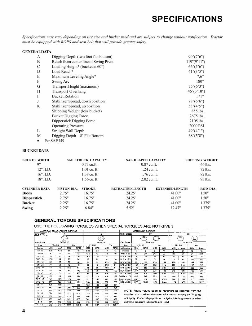
Specifications may vary depending on tire size and bucket used and are subject to change without notification. Tractormust be equipped with ROPS and seat belt that will provide greater safety.
GENERAL DATAA Digging Depth (two foot flat bottom) 90"(7’6")B Reach from center line of Swing Pivot 119"(9’11")C Loading Height* (bucket at 60°) 66"(5’6")D Load Reach* 41"(3’5")E Maximum Leveling Angle* 7.6°F Swing Arc 180°G Transport Height (maximum) 75"(6’3")H Transport Overhang 46"(3’10")I Bucket Rotation 171°J Stabilizer Spread, down position 78"(6’6")K Stabilizer Spread, up position 53"(4’5")
Shipping Weight (less bucket) 855 lbs.Bucket Digging Force 2675 lbs.Dipperstick Digging Force 2105 lbs.Operating Pressure 2000 PSI
L Straight Wall Depth 49"(4’1")M Digging Depth—8’ Flat Bottom 68"(5’8")• Per SAE J49
BUCKET DATA
BUCKET WIDTH SAE STRUCK CAPACITY SAE HEAPED CAPACITY SHIPPING WEIGHT9" 0.73 cu.ft. 0.87 cu.ft. 46 lbs.12" H.D. 1.01 cu. ft. 1.24 cu. ft. 72 lbs.16" H.D. 1.38 cu. ft. 1.76 cu. ft. 82 lbs.18" H.D. 1.56 cu. ft. 2.02 cu. ft. 93 lbs.
CYLINDER DATA PISTON DIA. STROKE RETRACTED LENGTH EXTENDED LENGTH ROD DIA.Boom 2.75" 16.75" 24.25" 41.00" 1.50"Dipperstick 2.75" 16.75" 24.25" 41.00" 1.50"Bucket 2.25" 16.75" 24.25" 41.00" 1.375"Swing 2.25" 6.84" 5.52" 12.47" 1.375"

5
SPECIFICATIONS
LM
D
8’
StraightWall Depth
28”

6
Safety of the operator was aprime consideration in the designof this backhoe. Proper shield-ing convenient controls, simpleadjustments and other safety fea-tures have been built into thisbackhoe.
Accidents can be avoided if the following safety rulesare observed:
PREPARATION
Do not operate backhoe unless it is rigidly attached tothe tractor.Know your controls. Read this operator’s manual and themanual provided with your tractor. Learn how to stop thetractor; the engine; and the backhoe quickly in an emer-gency.Provide adequate front end weight to counter balancethe backhoe at all times.Be sure the area is clear of underground utilities or otherhazards.Position a barricade around the work area.Keep all bystanders a safe distance away.
OPERATIONNever allow anyone to operate the backhoe who is notfamiliar with safe operating practices.Do not attempt to enter operator’s platform by using sta-bilizers as a step.Operate from the backhoe operator’s seat only.Allow only one person to operate the backhoe at a time.Never dig with backhoe unless stabilizers are properlyset.Do not dig under stabilizers or tractor with backhoe. Softground or sandy soil can cause cave-ins.Always swing bucket uphill to dump when on a hillside,Keep loaded bucket low.Set brakes and lock wheels when operating on hills andbanks to avoid dangerous run-away.Watch for overhead wires. Do not touch wires with anypart of backhoe.
Never allow a person to work under a raised bucket.
Always lower bucket to ground when not digging.Never leave tractor unattended with engine running.
TRANSPORTATION
Do not drive tractor near the edge of a ditch or excavation.Always use accessory lights when transporting on a road orhighway to warn operators of other vehicles.Check your local government regulations.
ADJUSTMENTS AND INSPECTION
Check hardware that attach backhoe to tractor and all pivot pinsfor tightness several times daily. Replace any parts that arebent, broken or missing.Do not oil, grease or adjust backhoe while it is in motion.Do not change any backhoe relief valve settings. They are fac-tory set for best backhoe performance and safety.
CAUTION: Escaping hydraulic fluid underpressure can penetrate skin causing seriouspersonal injury.
DO NOT use your hand to check for leaks. Use a piece ofcardboard or paper to search for leaks.
Stop engine and relieve pressure before connecting or dis-connecting hydraulic lines.
Tighten all connections before starting engine or pressur-izing lines.
If any fluid is injected into skin, obtain medical attentionimmediately or gangrene may result.
Be sure to relieve all pressure before disconnecting lines. Besure all connections are tight and that lines, pipes and hoses arenot damaged before applying pressure to the system.Do not remove any guards on backhoe or tractor.
Do not use bucket as a battering ram.
Whenever you see this symbol It means: ATTENTION! BECOME ALERT!
YOUR SAFETY IS INVOLVED!
SAFETY PRECAUTIONS
7
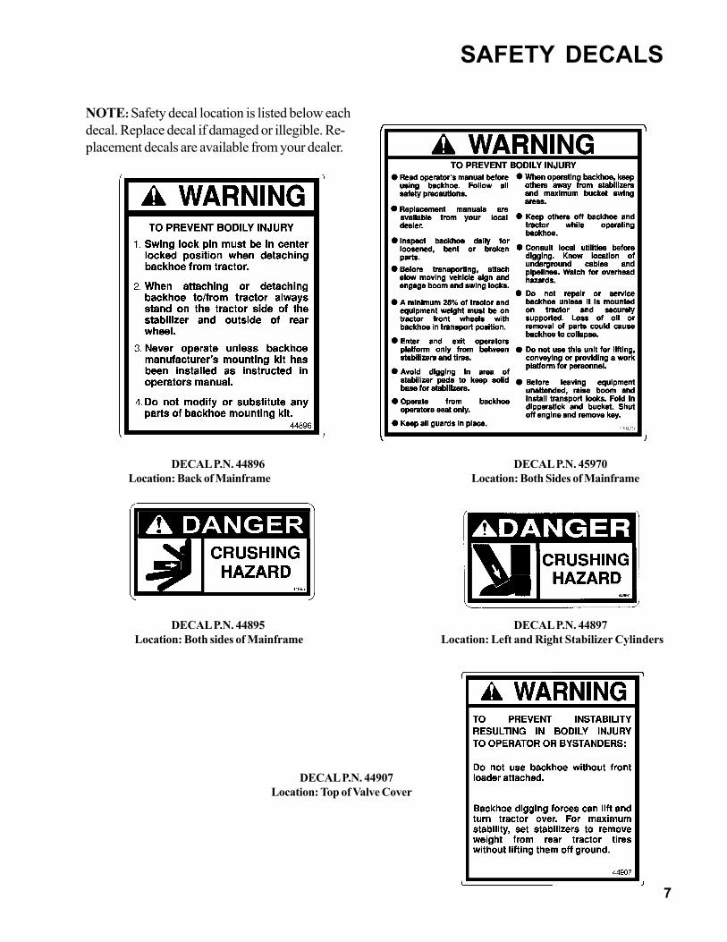
DECAL P.N. 44907 Location: Top of Valve Cover
DECAL P.N. 44895 DECAL P.N. 44897 Location: Both sides of Mainframe Location: Left and Right Stabilizer Cylinders
DECAL P.N. 44896 DECAL P.N. 45970Location: Back of Mainframe Location: Both Sides of Mainframe
NOTE: Safety decal location is listed below eachdecal. Replace decal if damaged or illegible. Re-placement decals are available from your dealer.
SAFETY DECALS

8
CAUTION: To avoid possible injury,observe the following safety rulesBEFORE OPERATING backhoe.
Be sure area is clear of underground utilities orother hazards.Position a barricade around work area.Keep bystanders a safe distance away.
PRE-OPERATION CHECK LIST
This backhoe is designed for safety, durability andoperator convenience. To insure satisfactory perfor-mance complete the following check list and make allnecessary adjustments before initial operation.1. All safety shields must be in place.2. Safety and operation decals must be in place,
undamaged and clean.3. Hydraulic hookup must be correct and all connec-
tions tight.4. All hardware which attach backhoe to tractor must
be properly torqued and in place.5. Tractor must be in proper operating condition.6. Lubricate backhoe, see “SERVICE”.7. Controls must operate properly. See “GENERAL
OPERATION”.8. Cycle all cylinders slowly to purge air from hydrau-
lic system.
OPERATING DIRECTIONS
The terms right, left, front and back shall be from theposition of the operator when seated in the operatingposition on the backhoe.ENGINE SPEED
Speed at which backhoe operates is dependent ontractor RPM. Use a moderate engine speed to start andincrease it as your experience permits.
CONTROLS
The backhoe has two major control levers, Boom/Swingand Crowd/Bucket. These controls are located on thecontrol panel directly ahead of the operator .The stabilizer control levers are located between the twomajor control levers.
BOOM/SWING
Push lever forward, boom moves down, away fromoperator. Pull lever back, boom moves up, towardoperator.Move lever to left, backhoe swings left. Move lever toright, backhoe swings right.
By moving lever to one of the intermediate positions, boomcan be swung left or right at the same time as it is beingraised or lowered, performing two operations simulta-neously.
Swing left and lower boom by moving control leverforward and to the left.Swing left and raise boom by moving control lever backand to the left.Swing right and lower boom by moving control leverforward and to the right.Swing right and raise boom by moving control leverback and to the right.
CROWD/BUCKET
Push lever forward, dipperstick moves away fromoperator. Pull lever back, dipperstick moves towardoperator.Move lever to left, bucket curls in. Move lever right,bucket extends out.By moving lever to one of the intermediate positions,dipperstick can be extended or retracted at the sametime as bucket is being loaded or dumped.Move dipperstick away and extend bucket by movinglever forward and to the right.Move dipperstick toward operator and curl bucket bymoving lever back and to the left.Move dipperstick away and extend (dump) bucket bymoving lever forward and to the right.Move dipperstick toward operator and extend bucketby moving lever back and to the right.
The two operations of the boom and swing lever combinedwith the two operations performed by bucket anddipperstick control lever provide four simultaneous opera-tions from the two levers. Oil flow will go to operation whichrequires the least pressure. The ability to feather valvespools and balance pressure comes with experience result-ing in reduced cycle times.
OPERATION

9
LEFT HAND STABILIZERPush lever forward, left hand stabilizer lowers. Pull leverback, left hand stabilizer raises.
RIGHT HAND STABILIZERPush lever forward, right hand stabilizer lowers. Pull leverback, right hand stabilizer raises.
OPERATING BACKHOECAUTION: To avoid possible injury,observe the following safety rulesWHEN OPERATING backhoe.
Operate from backhoe operators seat only.
Lower stabilizers until weight of tractor is supportedby stabilizers. Do not lift tractor tires off ground.
Do not dig near stabilizers.
Do not attempt to raise tractor off ground or movetractor forward or backward using backhoedipperstick or bucket.
Do not lose stability by swinging bucket downhillwhen positioned on a slope.
It is not difficult to become an efficient operator. Controloperating decals are located in front of control levers.Study these decals. They will assist you in becomingfamiliar with the controls.
Smooth, light handling of controls will result in the mostefficient backhoe operation.
Operate backhoe control levers to become familiar withtheir speed and movements. Engine RPM will determinespeed of cylinder operation.
Swing boom several times to practice controlling thespeed of swing. Do not operate swing more than 45degrees each way for the first few times. Graduallyincrease the arc.
Best results are obtained by digging near center of swingarc so material can be dumped on either side.
As operator becomes more familiar with operation ofbackhoe, it will be common practice to operate twocontrols at one time. For example with bucket extendedand dipperstick extended, the lift control and crowdcontrol can be operated together to bring bucket towardoperator with down pressure on it. As dipperstickapproaches operator, the crowd and bucket controls canbe operated together to close bucket and trap material.At end of stroke, lift and crowd controls are operated to
move load up and away from operator to save time inclearing excavation.
This dual operation of controls will speed and simplifydigging operation. Normally two or more movements will notbe equal or even simultaneous but as pressure within thecylinders, and as resistance of an operating member ofbackhoe lessens, it will begin to move. It is balancing theforce of one member against another.
NOTE: Actuating bucket is the key to powerful digging.Operating the crowd and bucket controls simultaneouslywill insure a full bucket and prevent wasted motion andtime.
OPERATION

10
OPERATIONMOUNTING AND DISMOUNTING BUCKETS
Standard Bucket:
Mount standard buckets using 1 x 6-5/8 anti rotationpins (1), 3/8 x 1-1/8 cap screws (2) 3/8 jam nuts (3), 3/8flat washers (4) and 3/7 lock nuts (5).
NOTE: Wrench flats of jam nut should fit into hole inpin ear.
PLACING THE STABILIZERS
Set the stabilizers to remove weight from the rearwheels. Rear wheels are to remain touching the groundas this provides for the widest stabilizer stance andlowest center of gravity
Raising the wheels off the ground will not only reduce stabilityand digging depth, but impair performance and impose unneces-sary stress on the backhoe and tractor.
SWING LOCK
Use swing lock when transporting or dismounting backhoe.Position boom straight back and drop pin through holes inswing frame and mainframe. Store pin in hole provided onmainframe.
BOOM LOCK
Use boom lock when transporting backhoe.
1. Completely raise boom and lower dipperstick.2. Secure boom using boom lock pin and hair pin clip.

11
SERVICE
CYLINDER SERVICE
Cylinders are designed to be reliable and easy to service. If acylinder should malfunction during warranty period, returncomplete cylinder assembly, without disassembling, to yourauthorized service department or contact your authorized servicedepartment for instructions. Unauthorized disassembly of acylinder in warranty period will VOID WARRANTY.
Following is an outline procedure for disassembling andreassembling cylinders.
CYLINDER
1. Hold cylinder tube (13 figure 6A) stationary and pull wirering (14) out through slot. Rotate head (6) to ease disassem-bly.
2. Pull shaft (1), with all assembled parts, out of cylindertube.
NOTE: Resistance will be felt until piston seal (10) slides overwire retaining ring groove. Seal is usually damaged whencylinder is disassembled.3. Remove lock nut (12) from end of shaft and slide piston (9)
and cylinder head (6) off shaft.4. Remove piston wear ring (11), piston seal (10), and o-ring
(8) from outside grooves on piston (Swing cylinders haveadditional steel ring between piston and nut).
5. Remove wiper seal (2), rod seal (3) and wear ring (7) frominside of cylinder head and o-ring (5) with backup washer(4) from groove on outside of head.
6. Clean all parts including cylinder tube, in a suitable cleaningsolvent, and then use air pressure to blow any dirt or excesssolvent from all parts.
7. Examine all parts for wear or damage and replace, ifnecessary.
CYLINDER ASSEMBLY
NOTE: Be careful not to damage seals and o-rings on edges orholes in cylinder tube. Inspect and remove burrs and sharp edgesif necessary before reassembly.
1. Place rod seal (3) into groove inside cylinder head.
NOTE: Lips of seal (3) must face inward and seal must be firmlyseated in groove (Figure 6B). For easier installation, place seal(3) in 120°F water to warm seal.
2. Install wiper seal (2) with lip of seal facing out and flushwith top of cylinder head. Install wear ring (7) inside otherend of head.
3. Place o-ring (5) with back-up washer (4) in groove onoutside of head. Back-up washer must be on rod side.
4. Remove sharp edges on outer edge of threaded end of shaft(1). Lubricate wiper seal (2) and rod seal (3) in head andcarefully slide head onto shaft.
5. Place o-ring (8), piston seal (10) and piston wear ring (11)in grooves on outside of piston.
NOTE: For easier installation, place piston seal (10) in 120°Fwater to warm seal.
6. Slide piston onto threaded end of shaft and install lock nut(12). Swing, bucket and stabilizer cylinders, tighten lock nut(12) to 300 ft. lbs. Lift and dipperstick cylinders tightenlock nut (12) to 375 ft. lbs. on lift cylinders.
7. Lubricate piston wear ring (11) and piston seal (10) onpiston, o-ring (5) and backup washer (4) on head and insideof cylinder tube (13), then carefully slide piston and headinto cylinder tube.
Insert wire retaining ring (14) into slot in cylinder tube (13).Apply pressure to wire ring to thread it into groove whileturning cylinder head.
12
SERVICECAUTION: To avoid possible injury,observe the following safety rules whenservicing backhoe.
Do not oil, grease or adjust backhoe while it is inmotion.
Do not change any backhoe relief valve settings.Relief valve settings are factory set for best backhoeperformance and safety.
Escaping fluid under pressure can have sufficientforce to penetrate the skin and cause serious injury.Be sure to relieve all pressure before disconnectinglines. Be sure all connections are tight and that lines,pipes and hoses are not damaged before applyingpressure to the system.
Fluid escaping from a very small hole can be almostinvisible. Use a piece of cardboard or wood - not yourhands - to search for suspected leaks.
See a doctor at once if injured by escaping fluid.Serious infection or reaction can develop if propermedical treatment is not administered immediately.
Protect your eyes - wear safety glasses. Guardagainst injury when driving connecting pins orperforming any repair in which particles can chip fromwork piece or striking tool.
BEGINNING OF SEASON
Remove all protective covering. Remove excessivegrease from cylinder rods if unit has been in long termstorage.
Check hydraulic hoses for deterioration and replace ifnecessary. Caution hydraulic hoses may be underpressure. Make sure pressure has been relievedbefore removing hoses.
Lubricate all grease fittings and oil handle linkage.
Clean and inspect all safety and operation decals.Replace missing or damaged decals.
Replace oil filter.
Fill hydraulic fluid to proper level.
Tighten all loose bolts, nuts and set screws (Seetorque chart page 4).
Sharpen or replace worn bucket teeth.
Operate backhoe slowly for a short time before placingunit under full load.
Fully cycle backhoe through all movements severaltimes to purge air from the system.
HYDRAULIC HOSES
WARNING: Escaping hydraulic fluid underpressure can penetrate skin causing seriousinjury.
DO NOT use your hand to check for leaks. Use a pieceof cardboard or paper to search for leaks.
Stop engine and relieve pressure before connecting ordisconnecting lines.
Tighten all connections before starting engine orpressurizing lines.
Oil leaks on the suction side will draw air into the system,causing oil in reservoir to appear foamy.
When tightening connections always use two wrenches.
IMPORTANT: Do not over tighten fittings. Make themjust tight enough to eliminate leaks.
NOTE: Apply sealant only to all tapered threads unlesscoupled with swivel adapters. When using teflon tape,wrap tape clockwise (as viewed from end) and wrap tapeonly twice. Keep sealant away from first two threads oftapered end to prevent contamination of hydraulic fluid.Do not use sealant on o-ring or flare adapter threads.
Hoses on backhoe are very severely worked and will fail intime. Examine them regularly and replace any that showsigns of failure. Pay careful attention to routing of hoses sothey can move freely, without kinking and cannot bepinched or cut by any part of backhoe.

13
SERVICE ITEM NO. LOCATION DESCRIPTION QTY. TOTAL
1 Rod, Stabilizer Cylinders 2 2 Rod, Swing Cylinders 2 3 Base, Stabilizer Cylinders 2
4 Base, Boom Cylinder 1 5 Rod, Boom Cylinder 1 6 Base, Crowd Cylinder 1 7 Rod, Crowd Cylinder 1 8 Boom-Dipperstick Pivot 1 9 Base, Bucket Cylinder 1 10 Rod, Bucket Cylinder 1 11 Bucket- 4-Bar Link 1 12 Dipperstick-Bucket Pivot 1 13 Swing Post 2 14 Boom to Swing Frame 1 15 Upper Swing Cylinder Bearing 2 16 Lower Swing Cylinder Bearing 2 17 Dipper- 4-Bar Link 1
BUCKET TOOTH POINTS
Bucket tooth points are self sharpening and will requirelittle attention. However, points can be replaced whenthey become badly worn or broken.
Remove point from welded tooth shank by hammeringat “A” on tooth point or by driving a chisel at “B” , justbetween tooth point box section and tooth shank.Install new point and anchor it to shank by peening atlocation shown.
If a tooth shank breaks off, becoming lost or damagedso that it can not hold a tooth point, a new shankshould be welded to bucket.
TIGHTENING NUTS AND BOLTS
Periodically check to be sure all bolts and nuts are tight(See torque chart page 4).
Check all pivot pins for cotter pins, washers andretainers. If any are missing replace them.
LUBRICATION
Economical and efficient operation of backhoe isdependent upon regular and proper lubrication of allmoving parts with a quality lubricant.
All parts provided with grease fittings should belubricated with a good quality chassis lube type grease.If any grease fittings are missing, replace them immedi-ately. Clean all fittings thoroughly before using greasegun.
Lubricate all 23 grease fittings at least twice daily (Seechart for locations), once at the beginning of operationand again approximately half way through the work day.Grease hourly any joints that operate in water.
Control valve handle linkage should be oiled with SAE 30oil.
IMPORTANT: Avoid excessive greasing. Dirt collects onexposed grease and greatly increases wear. Aftergreasing wipe off excess grease from fittings

14

15
POSSIBLE CAUSE CORRECTIVE ACTION
17 Oil leakage past spoolseal into spool cap
If spool cap contains oil, replace spoolseal o-ring. If o-ring retainer is “belled”check for restriction from “out” portreservoir. See item 30.
18 Broken return springs Replace springs. See item 30.
19 Bent spool. Return for factory repair or replace withnew spool section. See item 30.
20 Foreign particles. Clean system and valve.
21Misalignment of controlhandle linkage or spoolbonnet.
Check linkage for binding condition;loosen bonnet, operate valve to realign,and retighten.
22 Spool not moved to fullstroke.
Spool travel should be 5/16" either way or5/8" total. See item 30.
23Relief valve setting incontrol valve too low ordefective.
Clean or overhaul relief valve or replacecartridge. Refer to VALVE SERVICEsection for proper PSI settings
24Overload relief valve incontrol valve stuck openor malfunctioning.
Clean relief. Do not disturb pressuresetting or replace cartridge.
25 Worn control valve. Replace control valve.
26 Check poppet in controlvalve not holding.
Clean check poppet(s) carefully. Ensurefree movement and proper seating orreplace check poppet(s). See item 30.
27 Damaged or worn spoolseals. Replace spool end seals.
28Check ball in anti-cavitation is stuck or notseated properly.
Clean anti-cavitation valve carefully.Assure that checks move freely and seatproperly or replace cartridge. See item 30.
29Valve cap and centerreturn mechanismbinding.
Loosen screws holding cap on valve (ref.Item#2 P.22). Operate valve spool andretighten screws.
30. This valve is a precision device and isnot intended for extensive fieldadjustment or repair. Field replacementparts are limited to seal kits, cartridges,valve sections and tie rod ends. Beyondreplacement of these parts, opening ofcheck cavities and certain relief valvecavities to examine for trapped dirt, orresetting main relief valve with the use ofa good pressure gauge, valve should bereturned for service.
Dirt and shreds of packing material are the usualcauses of valve malfunction. Be sure that oilsupply is kept clean. Use only factory suppliedpackings in cylinder repair. Fittings and hosesmust be clean before being removed.Pages 20 & 21 explain proper valve repairprocedure. Pages 22 & 23 illustrate valve and listsrepair parts.
NOTE: Pay close attention to all cautionwarning notes so valve will not have to bereturned to manufacturer for reconditioning.
Troubleshooting guide is designed to helpqualified individuals, with valve service training,correct minor problems which may develop. Ifvalve is under warranty do not attemptdisassembly for repairs. Contact your authorizeddealer.
HYDRAULIC TROUBLE SHOOTING

16
REPLACING SECTIONS
For clarification, the inlet cover [cover containingmain relief cartridge (18) ] will be called the left end ofthe valve assembly.Reassemble valve on a flat surface to insure propersection alignment.1. Remove handle assembly from section being
removed.2. Remove valve from backhoe.3. Thoroughly clean valve assembly.4. Before disassembly, mark each section numeri-
cally to avoid incorrect reassembly.5. Remove four hex nuts and lock washers from
right (outlet cover) end of valve.6. Slide outlet cover and each section off tie rods.7. Replace sections as needed. Reassemble valve.
NOTE: Refer to “Replacing Section Seals” if sealsneed to be replaced.
WARNING: Do not prelube O-ringsection seals prior to installation.Compression of lubricants candistort valve causing spoolbinding.
8. Torque stud nuts evenly to 15ft. Lbs .
CAUTION: If stud nuts are nottightened to proper torque, valvespools may bind or stick, or causeO-ring seals to extrude.
9. Reinstall handle assembly. Use locite 242 (blue)on all screws.
REPLACING SECTION SEALS
1. Disassemble valve as described in previoussection.
2. Remove old O-ring section seals. Be careful notto scratch or otherwise damage sealing surfaceareas.
3. Thoroughly clean O-ring counter bores andsurfaces of each valve section.
4. Place valve assembly on a flat surface forreassembly.
5. Replace four O-ring seals. Seal Kit contains thenumber of section seals required for one worksection/inlet cover.
6. Replace work sections on assembly studs inreverse order in which they were removed. O-ringcounter bores (with O-rings in place) should beto your right (downstream side of section) withinlet cover on your left.
NOTE: Use care when sliding work sections on tie rodsto avoid dislodging O-rings.
1. When all work sections and outlet cover are posi-tioned on the assembly studs, replace lock washersand nuts.
2. Torque stud nuts evenly 15ft. Lbs.
SPOOL SEAL REMOVAL
1. Remove handle assembly and clevis pin from spool.2. Remove bonnet and spool positioner assembly from
rear of the work section.3. Carefully slide spool out of valve housing.4. Remove old spool seals. Be careful not to scratch or
damage spool bore and sealing surfaces.5. Thoroughly clean both seal grooves and exposed end
of spool.
SPOOL SEAL INSTALLATION
1. Lightly oil and insert one new spool seal in handleend (front) seal groove of valve housing. Verify sealfit by carefully running your finger around exposededge of seal. Seal should have a perfect ridge with nokinks or twists.
2. Lightly oil valve spool and, starting from positionerend (rear), reintroduce spool into valve housing.
3. Slowly push spool past seal with a twisting motion.Stop when seal groove is exposed on positioner end.
CAUTION: Do not pull spool too far, asthis will allow seal in front groove toenter a spool groove. Seal may be cutwhen spool is pushed back.
4. Lightly oil and insert remaining spool seal in bonnetend seal groove. Verify seal fit by carefully runningyour finger around exposed edge of seal. Seal shouldhave a perfect ridge with no kinks or twists.
5. Return spool to center position with a twistingmotion.
6. Reattach spool positioner. Use loctite 242 (blue)thread locking compound on spool screw holdingpositioner parts to spool. Be careful not to overtorque this screw and twist it off. Use 7 ft. lb. maxi-mum torque. Slide bonnet in place. Replace bonnetscrews. Torque bonnet screws to 5-7 ft. lbs.
7. Replace spool clevis pin and handle assembly.
VALVE SERVICE

17
REPLACING DAMAGED BACKUP RINGS
Backup rings are installed at the factory using a specialsizing tool.
1. Do not replace backup rings offered in seal kitsunless original ring has been damaged.
2. If backup ring must be replaced, cut replacementbackup ring as shown.
CAUTION: Make only one diagonal cut in backupring. Do not cut backup ring into two pieces.
3. Slip backup ring over cartridge and into place.
INSTALLING “SC” SPOOL POSITIONER KIT (Item2 Figure 6)
1. Remove socket head cap screws and bonnet fromsection.
2. Remove spool from section. Follow instructions in“Spool Seal Removal” section except do notremove seals.
3. Replace parts in “SC” spool positioner kit.
NOTE: Spool screw on end of spool is loctited inplace. Do not replace unless it is damaged. If spoolscrew must be replaced, refer to “Replacing SpoolEnds” Section.
4. Replace spool in section. Refer to instructions in“Spool Seal Installation” section.
5. Replace bonnet and socket head cap screws.
REPLACING SPOOL ENDS
1. Spool extensions (handle end) are installed at thefactory using Loctite 262. Spool screws (positionerend) are installed at the factory using Loctite 242.Do not replace them unless they are damaged. Usefollowing procedure to replace them.
2. Remove spool from section. Follow instructions in“Spool Seal Removal Section” except do not removeseals.
3. Clamp spool using vice grips on land section ofspool not machined for valve bore.
4. Unscrew damaged end.
NOTE: Heat may be applied to loosen Loctite.
5. Clean threads with Loctite Primer and install usingLoctite 262 for handle ends and Loctite 242 forpositioner ends.
Replace spool in section. Refer to instructions in “SpoolSeal Installation” section.
VALVE SERVICE

18
VALVE SERVICE
NOTE: Relief cartridges (15), (16), and(17) are not repairable. If service otherthan to replace seal kit (1) is required,replace complete cartridge.

19
REPAIR PARTS - GRESEN V-10 (930300)
ITEM PART NO. DESCRIPTION Qty.
1 932001 SEAL KIT, Main Relief Cartridge (2150 psi) 1 2 932002 SPRING CENTER POSITIONER KIT (New Style “B”) 6 3 932003 SEAL KIT, Body Section 7 4 932004 PLUG, Port 1 5 932005 RISER, Right 1 6 932006 RISER, Left (Not Shown) 1 7 930279 HANDLE 2 8 930274 BALL 2 9 ** CREW, Cap, Socket Head, 1/4-28 x 3/4 6 10 930266 ROD END, Assembly 4 11 930273 ROD END 2 12 ** SCREW, Cap, 1/4-20 x 2, Grade 8 2 13 ** SCREW, Cap, Socket Head, #10-24 x 1-1/2 8 14 ** NUT, Hex, 1/4-28 6 15 932007 RELIEF, Work Port, 2500 PSI 3 16 932008 RELIEF, Work Port with Anti Cavitation, 2150 PSI 2 17 932009 RELIEF, Main 2150 PSI 1 18 ** NUT, Lock, 1/4-20 2 19 932010 STUD KIT (Includes 4 stud bolts) 1 20 932011 SEAL KIT, Relief (Work relief cartridges) 4 21 932012 PLUG, No Relief Cavity 2 22 932013 SEAL KIT, Spool (Includes 2 Seals) 6 23 932014 Mounting Bracket 2 24 932015 POWER BEYOND SLEEVE (Optional) 1 25 932016 PLUG KIT, Load Check 6 26 930284 BOOT 2 27 932017 SEAL KIT, Power Beyond 1 28 ** SCREW, Cap, 5/16-18 x 1 4 29 ** WASHER, Flat, 5/16 4 30 ** NUT, Lock, 5/16-18 4 31 932018 SEAL KIT, Work Port Plug 2 32 ** NUT, Hex, 1/4-20 2 33 930293 HANDLE KIT 2 34 932019 CLEVIS & PIN KIT 2 35 932020 INLET COVER 1 36 932021 OUTLET COVER 1 37 932022 VALVE SECTION, 4-Way, 3-Position 4
(Does not include items 16, 17, 19, 34 or 35) 38 932023 VALVE SECTION, with long spool (Does not include 16 or 17) 3
VALVE SERVICE
** PURCHASE LOCALLY

20
PARTS
21
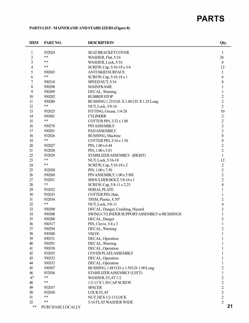
PARTSPARTS LIST - MAINFRAME AND STABILIZERS (Figure 8)
ITEM PART NO. DESCRIPTION Qty.
1 932024 SEAT BRACKET COVER 1 2 ** WASHER, Flat, 5/16 24 3 ** WASHER, Lock, 5/16 8 4 ** SCREW, Cap, 5/16-18 x 3/4 12 5 930265 ANTI SKID SURFACE 1 6 ** SCREW, Cap, 5/16-18 x 1 6 7 930318 SPEED NUT, 5/16 8 8 930298 MAINFRAME 1 9 930289 DECAL, Warning 110 930282 RUBBER STOP 211 930280 BUSHING 1.25 O.D. X 1.00 I.D. X 1.25 Long 212 ** NUT, Lock, 3/8-16 213 932025 FITTING, Grease, 1/4-28 1014 930301 CYLINDER 215 ** COTTER PIN, 3/32 x 1.88 216 930278 PIN ASSEMBLY 217 930281 PAD ASSEMBLY 218 932026 BUSHING, Machine 819 ** COTTER PIN, 3/16 x 1.50 820 932027 PIN, 1.00 x 6.44 221 932028 PIN, 1.00 x 5.81 222 932029 STABILIZER ASSEMBLY (RIGHT) 123 ** NUT, Lock, 5/16-18 1224 ** SCREW, Cap, 5/16-18 x 2 225 932030 PIN, 1.00 x 7.50 226 930268 PIN ASSEMBLY, 1.00 x 5.88I 227 932031 SHOULDER BOLT, 3/8-16 x 1 228 ** SCREW, Cap, 5/8-11 x 2.25 429 932032 SERIAL PLATE 130 932033 COTTER PIN, Hair, 131 932034 TRIM, Plastic, 8.50" 232 ** NUT, Lock, 5/8-11 433 930290 DECAL, Danger, Crushing, Hazard 234 930308 SWING CYLINDER SUPPORT ASSEMBLY w/BUSHINGS 135 930288 DECAL, Danger 236 930317 PIN, Clevis, 3/4 x 3 137 930294 DECAL, Warning 238 930300 VALVE 139 930331 DECAL, Operation 140 930291 DECAL, Warning 141 930330 DECAL, Operation 142 932035 COVER PLATE ASSEMBLY 143 930332 DECAL, Operation 144 930333 DECAL, Operation 145 930307 BUSHING, 1.88 O.D. x 1.50 I.D. 1.00 Long 246 932036 STABILIZER ASSEMBLY (LEFT) 1 47 ** WASHER, FLAT 1/2 248 ** 1/2-13 X 1.50 CAP SCREW 249 932037 SPACER 250 932038 LOCK FLAT 251 ** NUT, HEX 1/2-13 LOCK 252 ** 5/16 FLAT WASHER WIDE 2
** PURCHASE LOCALLY

22
PARTS
PARTS LIST - SWING POST AND SWING CYLINDERS
ITEM PART NO. DESCRIPTION Qty.
1 930296 PIN, 1.00 x 4.75 2 2 930287 BUSHING, Machine 8 3 ** SCREW, Cap, 3/8-16 x 2-1/2 3 4 930335 DECAL, Swinglock 1 5 ** NUT. Lock, 3/8-16 3 6 922021 PIN, 1-1/2 x 4.25 2 7 932039 FITTING, Grease, 1/8-27 3 8 ** COTTER PIN, 5/16 x 2.50 1 9 930308 CYLINDER, Swing 210 932026 BUSHING, Machine 411 930295 PIN, 1 x 7.25 112 930314 PIN, 1-1/4 x 7.25 113 930312 SWING FRAME ASSEMBLY 114 932040 LOCK FLAT 115 932025 FITTING, Grease, 1/4-28 216 ** NUT, Lock, 5/16-18 417 ** SCREW, Cap, 5/16-18 x 2 218 920282 CLAMP, U-Bolt 119 930304 BUSHING, 1.25 O.D. x 1.00 I.D. x 1.00 LONG 4
** PURCHASE LOCALLY
23
PARTS
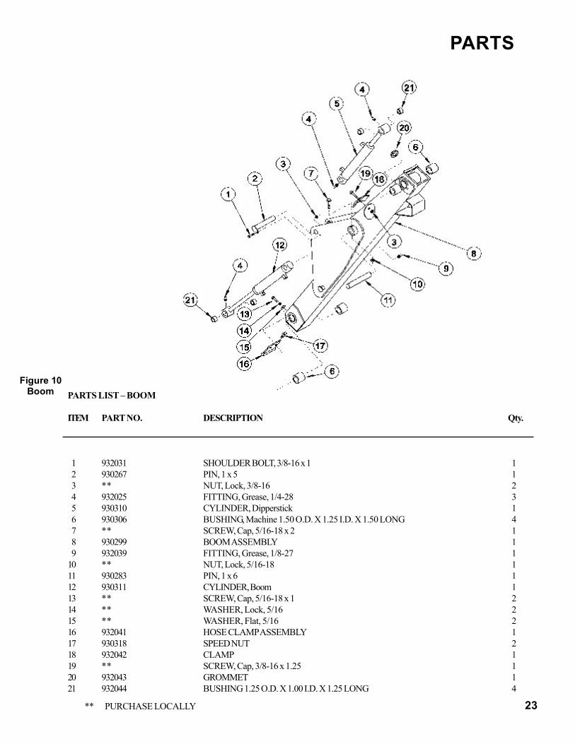
Figure 10Boom PARTS LIST – BOOM
ITEM PART NO. DESCRIPTION Qty.
1 932031 SHOULDER BOLT, 3/8-16 x 1 1 2 930267 PIN, 1 x 5 1 3 ** NUT, Lock, 3/8-16 2 4 932025 FITTING, Grease, 1/4-28 3 5 930310 CYLINDER, Dipperstick 1 6 930306 BUSHING, Machine 1.50 O.D. X 1.25 I.D. X 1.50 LONG 4 7 ** SCREW, Cap, 5/16-18 x 2 1 8 930299 BOOM ASSEMBLY 1 9 932039 FITTING, Grease, 1/8-27 110 ** NUT, Lock, 5/16-18 111 930283 PIN, 1 x 6 112 930311 CYLINDER, Boom 113 ** SCREW, Cap, 5/16-18 x 1 214 ** WASHER, Lock, 5/16 215 ** WASHER, Flat, 5/16 216 932041 HOSE CLAMP ASSEMBLY 117 930318 SPEED NUT 218 932042 CLAMP 119 ** SCREW, Cap, 3/8-16 x 1.25 120 932043 GROMMET 121 932044 BUSHING 1.25 O.D. X 1.00 I.D. X 1.25 LONG 4
** PURCHASE LOCALLY

24
25
PARTS
25
PARTS
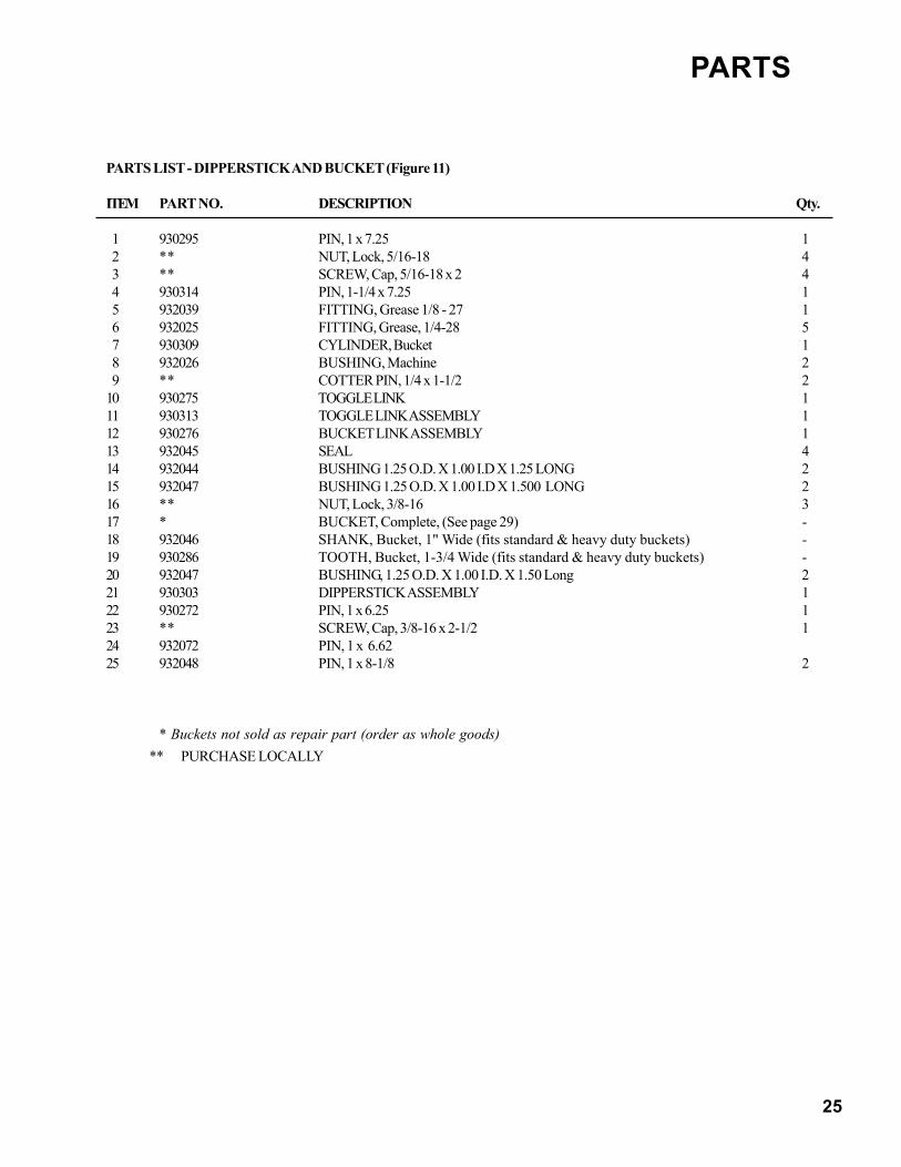
PARTS LIST - DIPPERSTICK AND BUCKET (Figure 11)
ITEM PART NO. DESCRIPTION Qty.
1 930295 PIN, 1 x 7.25 1 2 ** NUT, Lock, 5/16-18 4 3 ** SCREW, Cap, 5/16-18 x 2 4 4 930314 PIN, 1-1/4 x 7.25 1 5 932039 FITTING, Grease 1/8 - 27 1 6 932025 FITTING, Grease, 1/4-28 5 7 930309 CYLINDER, Bucket 1 8 932026 BUSHING, Machine 2 9 ** COTTER PIN, 1/4 x 1-1/2 210 930275 TOGGLE LINK 111 930313 TOGGLE LINK ASSEMBLY 112 930276 BUCKET LINK ASSEMBLY 113 932045 SEAL 414 932044 BUSHING 1.25 O.D. X 1.00 I.D X 1.25 LONG 215 932047 BUSHING 1.25 O.D. X 1.00 I.D X 1.500 LONG 216 ** NUT, Lock, 3/8-16 317 * BUCKET, Complete, (See page 29) -18 932046 SHANK, Bucket, 1" Wide (fits standard & heavy duty buckets) -19 930286 TOOTH, Bucket, 1-3/4 Wide (fits standard & heavy duty buckets) -20 932047 BUSHING, 1.25 O.D. X 1.00 I.D. X 1.50 Long 221 930303 DIPPERSTICK ASSEMBLY 122 930272 PIN, 1 x 6.25 123 ** SCREW, Cap, 3/8-16 x 2-1/2 124 932072 PIN, 1 x 6.6225 932048 PIN, 1 x 8-1/8 2
* Buckets not sold as repair part (order as whole goods)** PURCHASE LOCALLY
26
PARTS
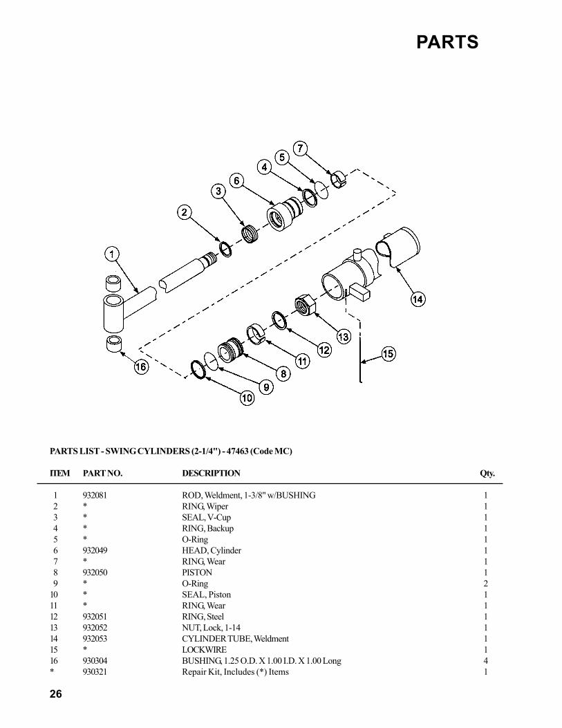
PARTS LIST - SWING CYLINDERS (2-1/4") - 47463 (Code MC)
ITEM PART NO. DESCRIPTION Qty.
1 932081 ROD, Weldment, 1-3/8" w/BUSHING 1 2 * RING, Wiper 1 3 * SEAL, V-Cup 1 4 * RING, Backup 1 5 * O-Ring 1 6 932049 HEAD, Cylinder 1 7 * RING, Wear 1 8 932050 PISTON 1 9 * O-Ring 210 * SEAL, Piston 111 * RING, Wear 112 932051 RING, Steel 113 932052 NUT, Lock, 1-14 114 932053 CYLINDER TUBE, Weldment 115 * LOCKWIRE 116 930304 BUSHING, 1.25 O.D. X 1.00 I.D. X 1.00 Long 4* 930321 Repair Kit, Includes (*) Items 1
27
PARTS
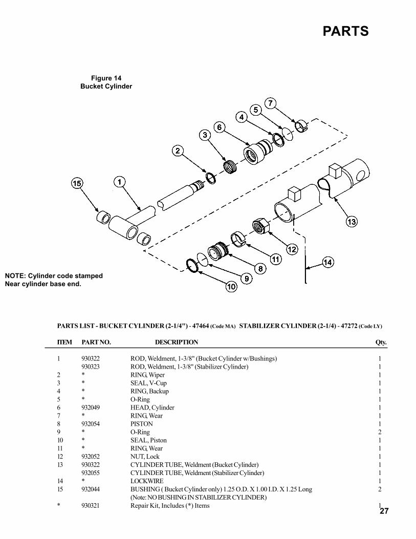
NOTE: Cylinder code stampedNear cylinder base end.
PARTS LIST - BUCKET CYLINDER (2-1/4") - 47464 (Code MA) STABILIZER CYLINDER (2-1/4) - 47272 (Code LY)
ITEM PART NO. DESCRIPTION Qty.
1 930322 ROD, Weldment, 1-3/8" (Bucket Cylinder w/Bushings) 1930323 ROD, Weldment, 1-3/8" (Stabilizer Cylinder) 1
2 * RING, Wiper 13 * SEAL, V-Cup 14 * RING, Backup 15 * O-Ring 16 932049 HEAD, Cylinder 17 * RING, Wear 18 932054 PISTON 19 * O-Ring 210 * SEAL, Piston 111 * RING, Wear 112 932052 NUT, Lock 113 930322 CYLINDER TUBE, Weldment (Bucket Cylinder) 1
932055 CYLINDER TUBE, Weldment (Stabilizer Cylinder) 114 * LOCKWIRE 115 932044 BUSHING ( Bucket Cylinder only) 1.25 O.D. X 1.00 I.D. X 1.25 Long 2
(Note: NO BUSHING IN STABILIZER CYLINDER)* 930321 Repair Kit, Includes (*) Items 1
Figure 14Bucket Cylinder

28
PARTS
Figure 15Lift Cylinder
NOTE: Cylinder code stampedNear cylinder base end.
PARTS LIST - LIFT CYLINDER (2-3/4") - 47466 (Code MB) DIPPER CYLINDER (2-3/4) - 47465 (Code MD)
ITEM PART NO. DESCRIPTION Qty.
1 932056 ROD, Weldment, 1-3/8" (Lift Cylinder) w/ Bushings 1932057 ROD, Weldment, 1-3/8" (Dipper Cylinder) w/ Bushings 1
2 * RING, Wiper 1 3 * SEAL, V-Cup 1 4 * RING, Backup 1 5 * O-Ring 1 6 932058 HEAD, Cylinder 1 7 * RING, Wear 1 8 932059 PISTON 1 9 * O-Ring 210 * SEAL, Piston 111 * RING, Wear 112 932060 NUT, Lock, 1-14 113 932061 CYLINDER TUBE, Weldment (Lift Cylinder) 1
932062 CYLINDER TUBE, Weldment (Dipper Cylinder) 114 * LOCKWIRE 1NS 930320 Repair KIt, Includes (*) Items 115 932044 BUSHING 1.25 O.D. X 1.00 I.D. X 1.25 LONG 2

29
BUCKET BUCKET STRUCKMODEL WIDTH CAPACITY
Inches Cubic Feet9 " 9 .7312" 12 1.0112" HD 12 1.0116" 16 1.3818" 18 1.5618" HD 18 1.5620" 20 2.1136" Grave 36 2.7836" Muck 36 2.78
PARTS
PARTS LIST - BUCKETS
ITEM PART NO. DESCRIPTION Qty.
1 930156 BUCKET, 9" -930012 BUCKET, 12” -930180 BUCKET, 16" -930181 BUCKET, 18" -932069 BUCKET, 24" -932070 BUCKET, Grave, 36" -
2 930286 TOOTH -3 932046 SHANK -

30
PARTS
31
PARTS
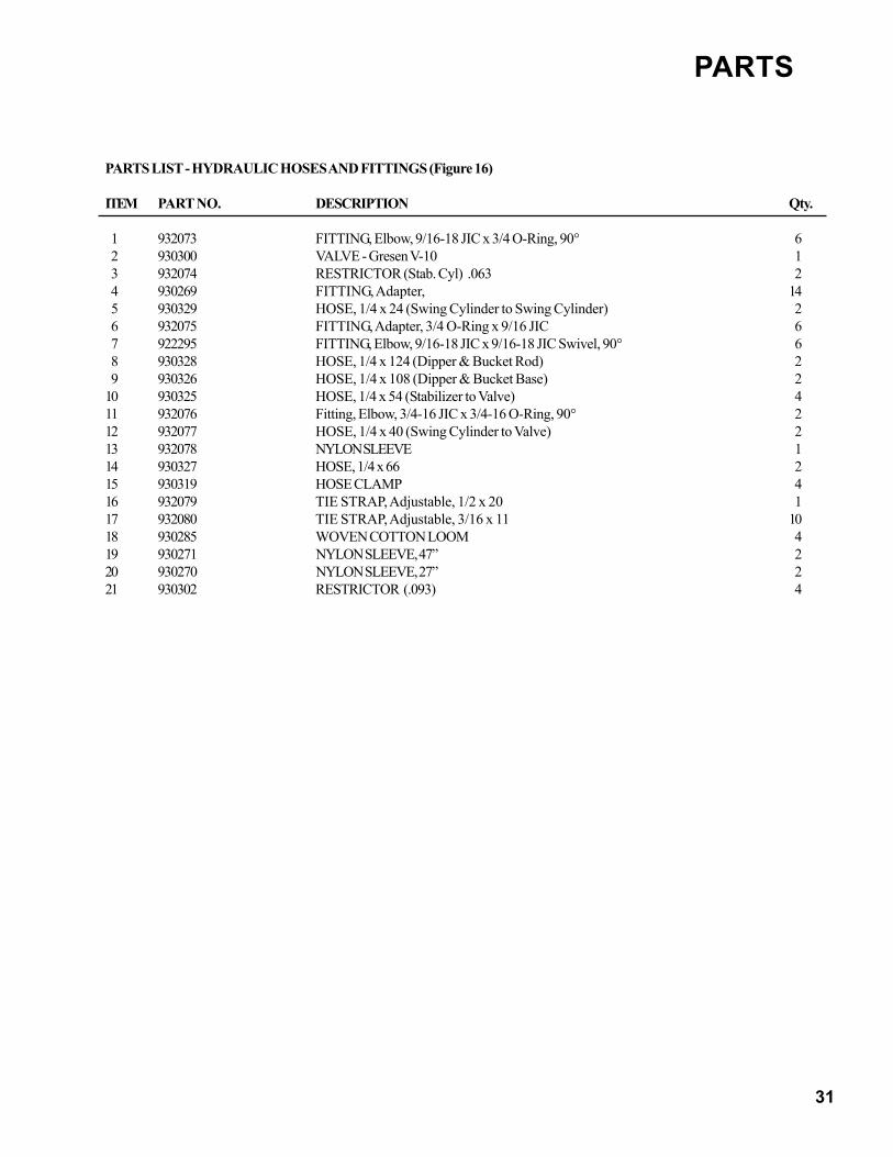
PARTS LIST - HYDRAULIC HOSES AND FITTINGS (Figure 16)
ITEM PART NO. DESCRIPTION Qty.
1 932073 FITTING, Elbow, 9/16-18 JIC x 3/4 O-Ring, 90° 6 2 930300 VALVE - Gresen V-10 1 3 932074 RESTRICTOR (Stab. Cyl) .063 2 4 930269 FITTING, Adapter, 14 5 930329 HOSE, 1/4 x 24 (Swing Cylinder to Swing Cylinder) 2 6 932075 FITTING, Adapter, 3/4 O-Ring x 9/16 JIC 6 7 922295 FITTING, Elbow, 9/16-18 JIC x 9/16-18 JIC Swivel, 90° 6 8 930328 HOSE, 1/4 x 124 (Dipper & Bucket Rod) 2 9 930326 HOSE, 1/4 x 108 (Dipper & Bucket Base) 210 930325 HOSE, 1/4 x 54 (Stabilizer to Valve) 411 932076 Fitting, Elbow, 3/4-16 JIC x 3/4-16 O-Ring, 90° 212 932077 HOSE, 1/4 x 40 (Swing Cylinder to Valve) 213 932078 NYLON SLEEVE 114 930327 HOSE, 1/4 x 66 215 930319 HOSE CLAMP 416 932079 TIE STRAP, Adjustable, 1/2 x 20 117 932080 TIE STRAP, Adjustable, 3/16 x 11 1018 930285 WOVEN COTTON LOOM 419 930271 NYLON SLEEVE, 47” 220 930270 NYLON SLEEVE, 27” 221 930302 RESTRICTOR (.093) 4

32