SMC Life Sciencecontent2.smcetech.com/pdf/Life_Science_MC01.pdf · 2016-10-06 · SMC’s...
84
CAT.M01 C SMC Life Science Analytical•Instrumentation•Microfluidics
Transcript of SMC Life Sciencecontent2.smcetech.com/pdf/Life_Science_MC01.pdf · 2016-10-06 · SMC’s...

CAT.M01 C
SMC Life Science
Analytical•Instrumentation•Microfluidics

SMC Life Science
Tsukuba Technical Centre
2

Table of Contents
Introduction
Technical Development
Production and Supply
Sales and Communication Network
Product Range
Related Markets
Custom Engineered Plastic Manifold & Valve Technology
Quality Assurance
Green Procurement
Flow Conversion/Calculations
International Training
Energy Saving Program
SMC’s Global Service Network
4
6
8
12
14
15
16
18
19
20
80
81
82
PageCorporate Guide
Products Index 21
Life Science Products
3

The 21st century — with the revolution in global information technology, business methods are undergoing great changes. In these quickly developing, ever changing times, customer satisfaction can only be achieved by a clear understanding of our customers’ goals and objectives. Therefore, SMC has built an organization that listens carefully to our customers, then responds quickly, and specifically, to their needs. SMC has established a widespread global network of locations in all major countries of the America’s, Europe and Asia showing our active commitment to the world market. SMC supports this global network with a stable supply chain of global products, a high level of technical service and solid communications network to meet our customers’ needs and expectations.
SMC is pursuing customer satisfaction and supporting automation worldwide through the design and production of the worlds most advanced pneumatic and fluidic control technologies
4

Sales and Communication Network
Technical Development
Production and Supply
Our engineering staff now exceeds 1,000 and are located in Technical centres in Japan, United States and Europe.
Quick, clear and detailed responses to customer requests are communicated through our sales group, and our engineers are constantly on the alert for new trends that lead to world class new products.
Our product line offers 10,000 basic models with over 560,000 variations. Global production facilities provide a stable supply of products to customers in all markets.
The vast array of products satisfies nearly every application. Fast delivery of these high quality products at competitive costs is accomplished through our unique production system, and by maximizing our local production capabilities, a stable supply of product is guaranteed.
Local subsidiaries have been established in 43 countries worldwide, with over 230 sales offices. Our sales force of over 4,000 maintains close communication with customers.
By establishing a strong base in each country and region with a large experienced sales force, SMC provides the best possible service in the industry. Maintaining close communication with our customers throughout the world keeps our engineering teams and our products at the leading edge of industry.
5

The Tsukuba Technical Centre has expanded into its newly completed twin-tower building. At the center of SMC’s research and development division, a staff of 1,000 is engaged in research and development activities for the entire world.
Following the basic concept of developing products from the customer’s standpoint, SMC is dedicating a large staff and large financial resources to research and development. This is undertaken to promote research on basic technology with future potential and to produce products that are adapted to the needs of the marketplace in a timely manner. To provide positive and speedy response to the problems presented by customers throughout the world, technical centers have been established in the United States and Europe, creating a powerful global engineering network with Japan as its nucleus. All of the technical centers share information and maintain close contact in order to quickly respond to requirements locally, and to offer the same high quality of technical service throughout the world.
Technical Development
Isolation Liquid 2/3 Port ValveSeries LVM
3 Port Solenoid ValveSeries V060
2/3 Port Solenoid ValveSeries VDW
3 Port Solenoid ValveSeries V100
3 Port Solenoid ValveSeries VQ100
Ultra Compact ValveSeries S070
Proportional ValveSeries PVQ
Electric ActuatorSeries LJ, LG, LX Electric Gripper
Digital Pressure SwitchSeries ISE/ZSE
Compact Electro-PneumaticRegulator. Series ITV
Menbrane Air DryerHeatless Air Dryer. Series IDG/ID
Custom Engineered Plastic Manifold & Valve Technology
To provide a global engineering network technical centres have been established in the United States and Europe, together with Japan
The Tsukuba Technical Center has expanded to a new twin-tower building from where it will oversee worldwide technical development.
6

The ETC is located close to SMC’s UK factory in Milton Keynes. Here, approximately 100 experienced engineers from SMC European subsidiaries are gathered to work on projects from their respective countries. This has enabled improved communication, faster and more accurate information exchange, and a higher level of customer satisfaction.
ETC (European Technical Centre) U. K.
The UTC has been established to meet the project requirements of customers in North America. The UTC has approximately 100 engineers available for customer support.
UTC (US Technical Centre) U. S. A.
UTC
ETC
SMC’s Global Engineering
NetworkJTC
7

Dies
Casting
Diecast
Dies
Clean room
Tool control
Aluminum casting machine line
Machining line (6-axis automatic machine tools)
SMC products reflect a market trend towards greater diversification with a vast array of 10,000 basic models and over 560,000 variations. This is made possible by an integrated production system that includes casting, machining, surface treatment, coating, assembly and inspection, all performed in SMC’s factories. Furthermore, we use a unique production control system in which instructions for all production operations are performed automatically based on information from orders received. As a result, SMC can secure high quality, optimised cost and a short lead time of its product.
Production and Supply
SMC’s integrated production system
Laboratory
High temperature test line
Test equipment for hydrofluoric and nitric acids
SMC’s unique production system achieves high quality, optimised cost and short lead times.
8

Production instruction for
Bin replenishment
SMC’s production control system
Order dataDelivery instruction
Factory
Stock productShipping
Customer
Part procurement Production
Machining Assembly Inspection
Electronic part
EDP
Customer orders are input directly by our salespersonnel. Once the order is entered into the SMC EDP system, items are automatically drawn from stock, or produced in our manufac-turing facilities. This is accomplished by the use of bin management systems.
Assembly and inspection of temperature controller
IC chip, being mounted on printed board
Bin control shelf
Loader, supplying work for part machining Piston rod machining line Coil winding
9

A global production network supports a stable and continuous supply of high quality productsthroughout the world.
SMC delivers products for world markets from five key factory locations in Japan, in the Tsukuba district of Ibaragi prefecture and the Soka district of Saitama prefecture, as well as from other key locations in China and Singapore. Additionally, to respond quickly and with increased flexibility to the demands of the local market, overseas production facilities have been established in SMC subsidiaries around the world.
Production and Supply
Soka Area (13 Factories/Saitama Prf.)
Soka Factory #1, New Building
Production Facilities (Japan)
Soka #1 Factory & #2 FactoryTotal Land Area: 24,945m2
Floor Space: 30,050m2
Canada SMC Pneumatics(Canada)Ltd.
U.S.A SMC Corporation of America (Indianapolis)
U.S.A SMC Corporation of America(Los Angeles)
Overseas Local Production Facilities
Canada
U.S.(Indianapolis)
U.S.(Los Angeles)
10

Kamaishi Factory (Iwate Prf.)
Tohno Factory (Iwate Prf.)
SMC (China) Co., Ltd.
Yamatsuri Factory (Fukushima Prf.)
Overseas Key Production Facilities
Total Land Area: 82,657m2
Floor Space: 41,623m2
Total Land Area: 124,227m2
Floor Space: 26,298m2
Total Land Area: 82,940m2
Floor Space: 55,352m2
Total Land Area: 79,428m2
Floor Space: 10,737m2
North/South AmericaChile SMC Pneumatics (Chile) S.A.Mexico SMC Corporation (Mexico), S.A.de C.V.Argentina SMC Argentina S.A.
Europa/AfricaSwitzerland SMC Pneumatik AGAustria SMC Pneumatics GmbH (Austria)Sweden SMC Pneumatics Sweden ABFrance SMC Pneumatique S.A.Spain SMC España, S.A.
Asia/OceaniaAustralia SMC Pneumatics (Aust.)Pty.Ltd.Singapore SMC Pneumatics (S.E.A.)Pte.Ltd.Malaysia SMC Pneumatics (S.E.A.)Sdn.Bhd.New Zealand SMC Pneumatics (N. Z.) Ltd.Hong Kong SMC Pneumatics (Hong Kong) Ltd.Taiwan SMC Pneumatics (Taiwan)Co.,Ltd.Philippines SMC Pneumatics (Phils.),Inc.Thailand SMC Thailand Ltd.India SMC Pneumatics (India) Pvt.Ltd.
Overseas Local Production Factories
Tsukuba Factory (Ibaragi Prf.)
Tsukuba #1 Factory & #2 FactoryTotal Land Area: 57,191m2
Floor Space: 45,094m2
U.K SMC Pneumatics (U.K) Ltd.
Italy SMC Italia S.p.A
Germany SMC Pneumatik GmbH
U.KGermany
Italia
Spain
Overseas Local Production Facilities
Overseas Key Production Facilities
Production Facilities (Japan)
KoreaChina
Singapore
Japan
Australia
Overseas Local Production Factories
SMC Manufacturing (Singapore) Pte. Ltd. Total Land Area: 23,942m2
Floor Space: 18,424m2
Korea SMC Pneumatics Korea Co.,Ltd.
Australia SMC Pneumatics (Australia) Pty.Ltd.
11

Our goal of 20% global market share has been achieved, with local subsidiaries in 43 countries across the world.
Taking its first step in Australia in 1967, SMC continued to move quickly into the international marketplace, and has steadily established local subsidiaries in the major countries around the world. The current total has reached 230 locations in 43 countries. With the expansion of its international network, SMC has earned a solid reputation as a reliable international brand, and has exceeded the goal of “20% global market share”. We will continue to view the world as a single market and further develop our sales organization with even greater energy to provide “customer satisfaction” by responding accurately to individual demands of different customers in countries and regions around the world.
U.S.A SMC Corporation of America (Indianapolis)
Mexico SMC Corporation (Mexico), S.A.de
Canada SMC Pneumatics (Cnada) Ltd.
U.S.A SMC Corporation of America.(Los Angeles)
North/South AmericaU.S.A SMC Corporation of AmericaChile SMC Pneumatics(Chile) S.A.Mexico SMC Corporation(Mexico), S.A.de C.V.Canada SMC Pneumatics(Canada)Ltd.Argentina SMC Argentina S.A.Bolivia SMC Pneumatics Bolivia S.r.l.Venezuela SMC Neumática Venezuela S.A.Brazil SMC Pneumáticos do Brasil Ltda.
Sales and Communication Network
12

Head office
Branch office
U.K SMC Pneumatics (U.K)
Italy SMC Italia
Spain SMC España, S.A.
Germany SMC Pneumatik
France SMC Pneumatique
China SMC (China)
SMC Pneumatics (Australia) Pty. Ltd.
Singapore SMC Pneumatics
Taiwan SMC Pneumatics (Taiwan)Co.,Ltd.
Korea SMC Pneumatics Korea Co.,Ltd.
Europa/AfricaItaly SMC Italia S.p.AU.K SMC Pneumatics (U.K) Ltd.Germany SMC Pneumatik GmbHSwitzerland SMC Pneumatik AGAustria SMC Pneumatics GmbH (Austria)Sweden SMC Pneumatics Sweden ABFrance SMC Pneumatique S.A.Ireland SMC Pneumatics (Ireland) Ltd.Spain SMC España, S.A.Czech Republic SMC Industrial Automation CZ s.r.o.Hungary SMC Hungary kft.Romania SMC Romania S.r.I.Slovenia SMC Industrijska Avtomatika d.o.o.Slovakia SMC Priemyselna Automatizacia Spol s.r.o.Finland SMC Pneumatics Filand OYNorway SMC Pneumatics Norway ASRussia SMC Pneumatik LLCDenmark SMC Pneumatik A/SPoland SMC Industrial Automation Polska Sp.z.o.oLatvia SMC Pneumatics Latvia SIAEstonia SMC Pneumatics Estonia OüThe Netherlands SMC Pneumatics B.V.Greece S. Parianopoulos S.A. (Distributor)South Africa Hyflo Southern Africa(Pty.)Ltd.(Distributor)
Asia/OceaniaAustralia SMC Pneumatics (Aust.) Pty.Ltd. SMC Singapore Pneumatics (S.E.A.)Pte.Ltd.Malaysia SMC Pneumatics (S.E.A.)Sdn.Bhd.New Zealand SMC Pneumatics (N. Z.) Ltd.Hong Kong SMC Pneumatics (Hong Kong) Ltd.Taiwan SMC Pneumatics (Taiwan)Co.,Ltd.Philippines SMC Pneumatics (Phils.),Inc.China SMC (China) Co.,Ltd.Thailand SMC Thailand Ltd.India SMC Pneumatics (India) Pvt.Ltd.Korea SMC Pneumatics Korea Co.,Ltd.Indonesia PT SMC Pneumatics IndonesiaIsrael Baccara Geva (Distributor)Turkey Entek Pnömatik San.ve Tic.Ltd.Sti. (Distributor)Japan SMC Corporation
13
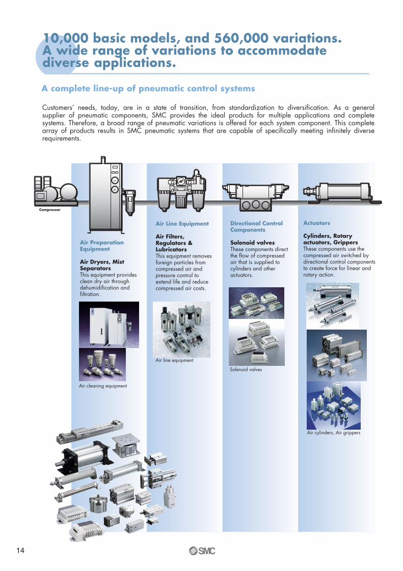
Air cylinders, Air grippers
Actuators
Cylinders, Rotary actuators, GrippersThese components use the compressed air switched by directional control components to create force for linear and rotary action.
Solenoid valves
Air line equipment
Air Line Equipment
Air Filters, Regulators & LubricatorsThis equipment removes foreign particles from compressed air and pressure control to extend life and reduce compressed air costs.
Directional Control Components
Solenoid valvesThese components direct the flow of compressed air that is supplied to cylinders and other actuators.
Compressor
Air cleaning equipment
Air Preparation Equipment
Air Dryers, Mist SeparatorsThis equipment provides clean dry air through dehumidification and filtration.
Customers’ needs, today, are in a state of transition, from standardization to diversification. As a general supplier of pneumatic components, SMC provides the ideal products for multiple applications and complete systems. Therefore, a broad range of pneumatic variations is offered for each system component. This complete array of products results in SMC pneumatic systems that are capable of specifically meeting infinitely diverse requirements.
A complete line-up of pneumatic control systems
10,000 basic models, and 560,000 variations. A wide range of variations to accommodate diverse applications.
14

SMC products are not confined to the limits of conventional pneumatic control components, but are reaching out to cover peripheral markets as well. SMC products are developed to satisfy unique requirements, and we are committed to developing products for new markets to satisfy all of our customers.
SMC products are moving into new-peripherals and pneumatics-related markets.
During the last twenty years pneumatics has moved into numerous industrial applications.
New technology productsProcess/Temperature control products
Wafer transfer productsClean room products
Clean wet productsHigh vacuum products
15

Series LVMIsolation liquid valvewith custom connection
Series VDWLiquid valve
Series PVQProportional valve
Series V100Air pilot valve
Custom machined/bonded plastic manifold
Reduced Space Reduced Weight Reduced Installation Time and Error Reduced Cost of Ownership
•••
Installation of valves onplastic manifold
Conventional System
Main specifications of Plastic Manifold Note)
MaterialFluidOperating pressureOperating temperatureAmbient temperature
Acrylic, ULTEM, PVC, Polysulpthone, etc.Air, Gas and Liquid-100kPa to 0.7MPa (30 inHg to 100psi)0 to 40oC (32 to 104oF)-5 to 50oC (23 to 122oF)
Note) Contact SMC for details
Custom Engineered Plastic Manifold & Valve Technology
Composite Valve Manifold for Air, Gas and Liquid
16

Series ISE/ZSEProgrammable liquid/airpressure switch withdigital display
Series VQ100Air pilot valve
Series S070Ultra Compact Valve7mm width valve
Tested and Packed to Customers Specifications
Ideal for equipment in• Medical Industry• Analytical Industry• Chemical Industry
SMC offers you the benefit of single Source Supply of plastic manifolds and valves!!• The widest selection of valves to suit the customers's exact specifications!• The best in-house design resources enables integrated and compact manifold design!• The best Before/After-sales services through world-wide network!
17

This is an international standard for quality control and quality assurance. SMC has obtained a large number of certifications in Japan and overseas, providing assurance to our customers throughout the world.
ISO9001 Quality management system
This is an international standard related to environmental management systems and environmental inspections. While promoting environmentally friendly automation technology, SMC is also making diligent efforts to preserve the environment.
ISO14001 Environmental management system
Quality control activities
Quality policies
Make customers our first priority,offering them reliable and friendly service.
Create new products using the latest technology,and offer the finest products in a timely manner.
Produce the highest quality with the participation of all employees.
Market researchProduct planningAfter sales service
Process controlInspection,testing,etc.Initial production quality control
New product evaluationReliability designReliability testingNew technical development
ResearchDesignDevelopment
EducationTraining
Sales coordination
ProductionQuality system educationTraining of suppliers
Applicable Products and ServicesDesign,development and manufacture of the following products:Miniature 3, 4 and 5 port solenoid valves for pneumatics.Standard compact cylinders for pneumatics.Standard miniature cylinders for pneumatics.Modular type pressure control valves for pneumatics.Pneumatic fittings.Electro-pneumatic positioners for pneumatics.Miniature rotary actuators for pneumatics.Solid state auto switches.Constant temperature circulation equipment for semiconductors.Vacuum ejectors(miniature type)
Related Facilities Included in the RegistrationTsukuba Technical Centre(design,development)Soka Factory No.1 (includes distribution center&Matsubara factory)Soka factory No.2 (manufacturing)Tsukuba factory No.1 (manufacturing)Tsukuba factory No.2 (manufacturing)Kamaishi factory (manufacturing)Yamatsuri factory (manufacturing)Tono factory(manufacturing)SMC Australia [ISO 9001]SMC China [ISO 9002]SMC Germany [ISO 9001]SMC Hong Kong [ISO 9002]SMC India [ISO 9002]SMC Italy [ISO 9002]SMC Italy (Sud) [ISO 9001/ISO14001]SMC Korea [ISO 9002]SMC New Zealand [ISO 9001]SMC Singapore [ISO 9002]SMC Spain [ISO 9002]SMC Sweden [ISO 9002]SMC Switzerland [ISO 9002]SMC Taiwan [ISO 9002]SMC UK [ISO 9001/ISO14001]SMC US [ISO 9001]
ISO certification obtained
Reliable product quality in the global market
Quality Assurance
SMC’s quality control system
To enable our customers throughout the world to use our products with even greater confidence, SMC has obtained certification for international standards “ISO9001” and “ISO14001”, and have created a complete structure for quality assurance and environmental controls. SMC products aspire to meet its customers’ expectations while also considering the company’s contribution in society.
18

SMC's Product Supply Plan Based On the RoHS Directive
SMC's Activities for Green Procurement
EU directives
RoHS directive
RoHS directive
WEEE directive
February 2003 RoHS directive proclamation
July 2006 RoHS directive enforcement
The RoHS directive compels EU membership countries to abolish or reduce the use of heavy metals such as mercury, lead, cadmium and hexavalent chrominum as well as bromic fire retardants such as PBB and PBDE by June 30, 2006.
RoHS-compliant product supply plan for customers who need them.
Respond to the requirementsfrom individual customers Standardized
Hg, PBB completeddisposal
ISO9001 acquiredQS9000 acquiredISO14001 acquired Pb, Cd,
Cr (VI), PBDE now being reduced
Feb. 2003RoHS proclamation
July 2006RoHS enforcement
SMCobservance plan
Waste Electrical and Electronic Equipment∗ Directive for collecting and recycling electrical and electronic equipment waste
The Restriction of the use of certain Hazardous Substances in electrical and electronic equipment∗ Directive for restricting 6 specific substances contained in electrical
and electronic equipment
Mercury, Lead, Cadmium, Hexavalent Chromium,PBB, and PBDE
RoHS bans : Hg (Mercury)Pb (Lead)Cd (Cadmium)Cr (VI) (Hexavalent chromium) PBB, PBDE(Certain bromic fire retardant)
Although industrial products, including pneumatic products, are not subject to WEEE & RoHS directives, SMC nonetheless strives to meet the needs of our customers.
Following the announcement of the latest EU (European Union) directive on environmentally harmful substances, customers requesting Green Procurement options has increased substantially.
The sale of products containing environmentally hazardous substances subject to the RoHS directive will be prohibited in the EU.
Please consult us when the products containing environmentally hazardous substances out of the scope of the RoHS directive or domestic legal requirements, etc. are required.
19

Flow Characteristicsand Measurement
Liquids
∆PSG
Q = N1 • CV •
P = Q2 • (SG)
N12 CV
2
Flow rate:
Pressure drop:
P12 P2
2
(SG) • TQ = N2 • C V •
N3 • CV • P1
(SG) • TQ = (1)
P2 P1
2
(1)
18
0.055
114
4.4
0.001
981.5
54.4
4
0.0
18
1.
17
0.8
6
21
0.06
28x10-6
0.0357x10⁶
16.67
0.0
009
0.0417x10 -6
Av Kv
Cv S
Qn
kv
Relative density of liquids
Liquid
AcetoneAlcoholBenzeneGasolineKeroseneWater
Relative density related to waterG at 20°C0.7920.7920.9020.9020.8151.000
Q = Flow rate m3/h∆P= Pressure drop (bar, absolute) / 1bar ~ 0.1 MPaN1 = Conversion value 0.865G = Relative density, [water 1.0]CV = Valve flow rate
Gases Relative density of gases
Liquid
AmmoniaArgonAcetyleneButaneHeliumCarbon dioxideMethanePropaneOxygenSulphur dioxideNitrogen Hydrogen
Relative density related to waterG at 20°C0.5871.380.9072.070.1371.5290.5541.5621.1052.2640.9670.0695
Q = Flow rate m3/hCV = Valve flow rateN2 = Conversion value for 295N3 = Conversion value for 250T = Gas temperature °K (°C = + 273)∆P = (P1— P2) Pressure drop in bar (absolute) / 1 bar ~ 0.1 MPaP1 = Supply pressure in bar (absolute)P2 = Output Pressure in bar (absolute)G = Relative density
≤
Conversion factors for different flow units 24x10 -6
0.048
The Kv conversion value indicates the quantity of warm water (from 5 to 40°C), expressed in m3/h, flowing through a valve which causes a pressure drop of 1 bar.
kv conversion value is equivalent to the Kv mentioned above, however converted to l/min.
The Cv-value common in the USA indicates, the quantity of water at 60°F, expressed in Gal/min, flowing through a valve which causes a pressure drop of 1 psi.
The Av flow rate coefficient is indicated in m2.
Qn indicates the volumetric flow rate of compressed air in l/min passing through a valve when the supply pressure is 6 bar and the pressure drops 1 bar.
Equivalent cross-section S (mm2) This indication determined by air measurement refers to a valve or a whole arrangement of elements and corresponds to the cross-section area of the pertinent orifice plate opening with same flow.
20

21
Gas and Chemical Liquid Valve/Series LVM
Highly Integrated resin System
2/3 Port Valve for Water, Air, Vacuum/Series VDW
Process Valves for Various Fluids Control/Series VC
Process Valves for Various Fluids Control/Series VX
Process Valves for General Pneumatic Fluids/Series VN
Process Pump/Series P
22
25
26
27
28
29
30
Chemical/Liquid Valves
Miniaturization of equipment/Series Variations
Electric Actuators/Series Variations
59
60
Actuators
Custom Design Temperature Control and Water Related Equipment/Series Variations 74
Temperature Control Equipment
Vacuum Equipment/Series Variations
Vacuum Regulator/Series IRV
Application examples
76
78
79
Vacuum Equipment
Chemical Valve/Series LVHigh Purity Fluoropolymer Fittings & Tubing/Series LQ, TL/TIL
70
72
High Purity Components
Air Preparation Equipment/Series Variations
Air Filter/Series AF
Membrane Air Dryer/Series IDG
Pressure Regulation Equipment/Series AR
Precision Regulator/Series IR
Precision Clean Regulator/Series SRP
Clean Regulator/Series SRH
Clean Gas Filter/Series SF
Special Regulator for Oxygen Concentrator/Series SRA
Electro-Pneumatic Pressure Regulator/Series ITV
Refrigerated Air Dryer/Series IDFA
40
42
43
44
45
46
47
48
49
62
50
Air preparation
Electro-Pneumatic Pressure Regulator/Series ITV
Digital Pressure Switch/Series Variations
Digital Flow Switch/Series Variations
Ionizer with Surface Potential Sensor/Series IZS30
62
64
66
68
Instrumentation
ø2 Miniature Piping/Series KJ/M/AS/TU
Fittings & Tubing Overwiew
S Couplers/Series KK
51
52
58
Fittings & Tubing
SMC Life Science
Ultra Compact. 3 Port Solenoid Valve/Series S070
Ultra Compact. 5 Port Solenoid Valve/Series S0700
Compact Unit Manifold Valve/Series VV061
3 Port Solenoid Valve for Air/Series V100
3 Port Solenoid Valve for Air/Series VQ100
Compact Proportional Valve/Series PVQ
2 Port High Flow Diaphragm Valve/Series DXT474
Pinch Valve/Series XT34
32
33
34
35
36
37
38
39
Air Valves
21
Che
mic
al /
Liqu
id V
alve
sA
ir
Valv
esA
ir
prep
arat
ion
Fitt
ings
& T
ubib
gA
ctua
tors
Inst
rum
enta
tion
Hig
h P
urity
C
ompo
nent
sTe
mpe
ratu
re
Con
trol
Vacu
um
Equ
ipm
ent

Applications: Various analytical and inspection equipment
Analytical instruments for blood, urine, immune system, etc.
LVM11
A
C
B
For detailed dimensions, specifications, and delivery, please contact SMC.
Series LVM090Valve width: 9.5 mm
Series LVM200Valve width: 20 mm
Max. operating pressure
Orifice diameterFlow characteristics (Cv factor)
Series
0.2 MPa
1.1 mm
0.018
LVM0900.25 MPa
1.4 mm
0.03
LVM100
0.3 MPa
2 mm
0.065
LVM200Specifications
Meeting the most advanced needs of process control
Super Compact Direct Acting 2/3 Port Solenoid Valve for Chemicals Series LVM
Valve chamber volume of 20l or lessBody designed for smooth flow with minimal dead volume and superior elimination of residual liquid.
Internal volume — LVM11: 11 µl or less LVM1R, LVM11: 20 µl or less
∗ The internal volume enclosed by the body and the diaphragm
Wetted part material
Body and plate: PFA or PEEKDiaphragm: EPDM, FKM or FFKM can be selected. Note) FFKM is available as a special order.
Service life: 10 million cycles or more. Note) Based on SMC test conditions.
Power consumption:1W(LVM11)/1.5W(LVM1R,LVM11)
Lightweight: 30g (LVM11) /34g(LVM1R,LVM11)
Valve width:13mmValve width 9.5 mm (LVM090), 20 mm (LVM200) are also available.
22
Che
mic
al /
Liqu
id V
alve
sA
ir
Valv
esA
ir
prep
arat
ion
Fitt
ings
& T
ubib
gA
ctua
tors
Inst
rum
enta
tion
Hig
h P
urity
C
ompo
nent
sTe
mpe
ratu
re
Con
trol
Vacu
um
Equ
ipm
ent

Series LVM10/100
LVM1(Rocker type)
A Internal volumeB Body and plate material: PEEKC Diaphragm material: EPDM, FKM or Kalrez®
B
C
A
2-M5 x 0.8 Bracket(Optional)
Bracket (Optional)
Manual(Optional)
Tubing
O-ring
Body ported type
Series
LVM11 N.C. 2 port 1.5 mm
Valve type Port Orificediameter
0.04
Cvfactor
Series
LVM11R
LVM12R
LVM112
N.C.
N.O.
Universal
2 port
3 port
1.4 mm
Valve type Port Orificediameter
0.03
Cvfactor
Series
LVM13R
LVM14R
LVM16R
LVM115
N.C.
N.O.
N.C.
Universal
2 port
3 port
1.4 mm
Valve type Port Orificediameter
0.03
Cvfactor
Series
LVM13R
LVM14R
LVM16R
LVM115
N.C.
N.O.
N.C.
Universal
2 port
3 port
1.4 mm
Valve type Port Orificediameter
0.03
Cvfactor
Bracket (Optional)
Tubing type
Base mounted type (Without sub-plate)
Base mounted type (With sub-plate)
LVM10/100ES70-30
23
Che
mic
al /
Liqu
id V
alve
sA
ir
Valv
esA
ir
prep
arat
ion
Fitt
ings
& T
ubib
gA
ctua
tors
Inst
rum
enta
tion
Hig
h P
urity
C
ompo
nent
sTe
mpe
ratu
re
Con
trol
Vacu
um
Equ
ipm
ent

Valve construction
Valve type
Number of ports
Fluid Note 1)
Operating pressure range
Orifice diameter
Response time
Leakage
Proof pressure Note 2)
Ambient temperature
Fluid temperature
Volume of valve chamber
Mounting orientation
Enclosure
Weight
Rated voltage
Type of coil insulation
Power consumption
Coil switching noise
Diaphragm typedirect operated
poppetDiaphragm type direct operated poppet (Rocker type)
N.C.
2
0 to 0.25 MPa
1.5 mm
0.04
11 µl
30 g
N.C.
2
Air, Water, Pure water, Diluent, Cleaning solvent
10 ms or less
Zero leakage, either external or internal (at hydraulic pressure)
0.38 MPa
0 to 50°C
0 to 50°C (with no condensation)
Free
IP40 or equivalent
12, 24 VDC
±10% of rated voltage
Class B
50 dB
1.5 W
34 g (Without sub-plate), 42 g (With sub-plate)
20 µl
–75 KPa to 0.25 MPa
1.4 mm
0.03
3 32
ModelLVM115LVM14R LVM16RLVM13RLVM112LVM12RLVM11R
N.O. Universal N.C. N.O. N.C. Universal
LVM11
Specifications
Body ported type Body ported type(Tubing type)
Base mounted type(Without sub-plate)
Base mounted type(With sub-plate)
Note 1) Select an appropriate material for the wetted part when fluid such as a cleaning solvent is used. Also, be sure to confirm the fluid compatibility in advance.
Note 2) Indicates the pressure which does not generate breakage, cracks or external leakage after a one-minute airtight test.Note 3) Indicates the volume of clearance inside the valve chamber after the volume of the diaphragm is subracted.Note 4) Since the body (orifice shape) is designed to eliminate residual liquid, mounting in a vertical direction with the coil at the top is
recommended. When residual liquid is not considered, any mounting style is available.Note 5) When the response speed is regarded as important, prevent negative fluctuation of the voltage by adequate regulation.Note 6) The value is based on SMC’s measurement conditions. The noise level will vary with conditions.
Body ported type Body ported type (Tubing type) Base mounted type
2.5 W at inrush, 1 Wat holding (with built-
in power saving circuit)
Flow characteristics (Cv factor)
Allowable voltage fluctuation
Note 3)
Note 4)
Note 6)
Note 5)
Super Compact Direct Acting 2/3 Port Solenoid Valve for Chemicals Series LVM
24
Che
mic
al /
Liqu
id V
alve
sA
ir
Valv
esA
ir
prep
arat
ion
Fitt
ings
& T
ubib
gA
ctua
tors
Inst
rum
enta
tion
Hig
h P
urity
C
ompo
nent
sTe
mpe
ratu
re
Con
trol
Vacu
um
Equ
ipm
ent

Custom designed solutions
Equipment configuration by conventional air piping
Highly Integrated Resin System
Manifold Specifications
Material
Fluid
Operating pressure
Ambient temperature
Fluid temperature
PMMA, PVC, PEI, ULTEM, POLYCARBONATE & PSU
Air, Liquid (Check chemical compatibility)
-100KPa~0.7MPa
-5~50°C
0~40°C
Electrical board
Space saving
Simple piping
Mistakes in piping and wiring are prevented by elimination of complicated piping procedures.
A 3 dimensional configuration of fluid passages that is not achievable by drilling or injection molding is materialized by diffusion bonding technology. A variety of layouts are available to satisfy users’ needs.
Reduction of the footprint by integrating control equipment such as solenoid valves and sensors on a manifold.
Simple wiring
• Electrical wiring is simplified by integrating the printed circuit board onto the manifold.• Wiring labour is significantly reduced by integration of electrical wiring.
Light weight is achieved through use of resin manifolds.Acrylic, polyethermide, polycarbonate, polysulfone, Vinyl chloride are available.
Custom designed solutions only.
Composite Valve Manifold for Air, Gas and Liquid Made to Order
25
Che
mic
al /
Liqu
id V
alve
sA
ir
Valv
esA
ir
prep
arat
ion
Fitt
ings
& T
ubib
gA
ctua
tors
Inst
rum
enta
tion
Hig
h P
urity
C
ompo
nent
sTe
mpe
ratu
re
Con
trol
Vacu
um
Equ
ipm
ent

Series of compact designs
VDW10 VDW20 VDW30 VDW200 VDW300
ø20.5
High flow rate: Cv factor 0.03 to 0.44 (2 port)
Universal porting VDW200/300 (3 port)
Clip type
Bottom mounting threadsMounting bracket also available
ø17
ø28 ø20.5ø282 port 3 port
Threaded assemblySimplifies maintenance
Improved corrosion resistanceSpecial material introduced
Quick change coilsClip design makes coil replacement easy (2 port)
Brass/Stainless steel manifolds added to series (2 port)
2/3 Port Solenoid Valve for Water, Air and VacuumSeries VDW
Compact (compared to series VX)
Single valve volume: Reduced 75% (VDW20)
Manifold length: Reduced 18% (VDW30, 7 stations)
Light weight (compared to series VX)
100g: Reduced approx. 50% (for orifice size equivalent to ø2)
Improved durability (nearly twice the life of the previous series)
The use of a unique magnetic material reduces the operating resistance of moving parts, while improving service life, wear and corrosion resistance.
VDWES70-20
26
Che
mic
al /
Liqu
id V
alve
sA
ir
Valv
esA
ir
prep
arat
ion
Fitt
ings
& T
ubib
gA
ctua
tors
Inst
rum
enta
tion
Hig
h P
urity
C
ompo
nent
sTe
mpe
ratu
re
Con
trol
Vacu
um
Equ
ipm
ent

Process Valves for Various Fluids Control Series VC
VQ20/302 port solenoid valve for air
N.C.ø6, ø8, ø10, ø12
3.4~4.8[0.33~0.81]
VCW20/30/40Direct operated 2 port solenoid valve for water
• Body ported• Manifold N.C./N.O.
VDW10/20/30Compact direct operated 2 port solenoid valve for water and air
• Body ported• Manifold N.C.
VDW200/300Compact direct operated 3 port solenoid valve for water and air
• Body ported COM.
Series
VCA20/30/40Direct operated 2 port solenoid valve for air
TypeOrifice size (ømm)
[Flow (Cv)] Port sizeValvetype
• Body ported• Manifold
3~10[0.33~2.1]
1/4, 3/8,1/2, 3/4
N.C.
VCB20/30/40Direct operated 2 port solenoid valve for heated water
• Body ported1/8, 1/4, 3/8, 1/2,
3/4N.C.
VCL20/30/40Direct operated 2 port solenoid valve for oil
• Body ported• Manifold N.C.
VCS20/30/40Direct operated 2 port solenoid valve for steam
• Body ported• Manifold N.C.
1/8, 1/4, 3/8, 1/2,
3/4
1/8, 1/4, 3/8, 1/2,
3/4
1/8, 1/4, 3/8, 1/2,
3/4
M5, 1/8, 1/4
M5, 1/8, 1/4
2~10[0.16~2.1]
2~10[0.16~2.1]
2~10[0.16~2.1]
2~10[0.16~2.1]
1~4[0.04~0.44]
1~4[0.03~0.44]
∗ N.C.: normally closed; N.O.: normally opem; COM.: common
∗
• Body ported• Manifold
VCAES70-21
VCWE708
VCSES70-19
VCBES70-22
VCLES70-18
27
Che
mic
al /
Liqu
id V
alve
sA
ir
Valv
esA
ir
prep
arat
ion
Fitt
ings
& T
ubib
gA
ctua
tors
Inst
rum
enta
tion
Hig
h P
urity
C
ompo
nent
sTe
mpe
ratu
re
Con
trol
Vacu
um
Equ
ipm
ent

Process Valves for Various Fluids Control Series VX
VX31/32/33Direct operated 3 port for air, gas, vacuum, water, steam, oil
• Body ported• Manifold
N.C./N.O.COM.
VXA21/22, VXA31/32Direct operated 2/3 port for air, gas, vacuum, water, oil
• Body ported• Manifold
VXA21/22:N.C./N.O.VXA31/32:
COM.
Series
VX21/22/23Direct operated 2 port solenoid valve for air, gas, vacuum, water, steam, oil
TypeOrifice size (ømm)
[Flow (Cv)] Port size Valvetype
• Body ported• Manifold
2~10[0.17~2.20]
1/8, 1/4, 3/8, 1/2 N.C./N.O.
VXD21/22/23Pilot operated 2 port solenoid valve for air, gas, water, oil
• Body ported 1/4, 3/8, 1/2, 3/4, 1 N.C./N.O.
VXZ22/23Pilot operated 2 port for zero pressure differential/For air, gas, vacuum, water, oil
• Body ported N.C./N.O.
VXH22Pilot operated 2 port for hihg pressure/For air, water, oil
• Body ported N.C.1/4, 3/8,
1/2
1/8, 1/4, 3/8
10~25[1.9~13]
10~25[1.9~12]
10[1.9~2.4]
1.5~4[0.08~0.50]
VXA21/22:3~10 [0.33~2.4]
VXA31/32:1.5~4 [0.08~0.50]
∗
1/4, 3/8, 1/2, 3/4, 1
VXA21/22:1/8, 1/4, 3/8, 1/2
VXA31/32:1/8, 1/4, 3/8
∗ N.C.: normally closed; N.O.: normally opem; COM.: common
VX31/32/33EUS70-26
VXD21/22/23EUS70-29
VX21/22/23EUS70-23
VXP21/22/23Pilot operated 2 port solenoid valve for steam, air, gas, water, oil
• Body ported N.C./N.O.10~50
[1.9~49]1/4, 3/8, 1/2,
3/4, 1, 11/4, 11/2, 2
28
Che
mic
al /
Liqu
id V
alve
sA
ir
Valv
esA
ir
prep
arat
ion
Fitt
ings
& T
ubib
gA
ctua
tors
Inst
rum
enta
tion
Hig
h P
urity
C
ompo
nent
sTe
mpe
ratu
re
Con
trol
Vacu
um
Equ
ipm
ent

Process Valves for General Pneumatic Fluids Series VN
∗ N.C.: normally closed; N.O.: normally opem; COM.: common
VNC2 port valve for coolant applications
• Body ported
VND2 port valve for steam
• Body ported N.C./N.O.
7~50[1.25~100]
7~50[1.08~62]
1/8, 1/4, 3/8, 1/2, 3/4, 1,
1 1/4, 1 1/2, 2N.C./N.O.
1/8, 1/4, 3/8, 1/2, 3/4, 1,
1 1/4, 1 1/2, 2
Series TypeOrifice size (ømm)
[Flow (Cv)] Port size Valvetype
∗
VNA2 port valve for compressed air and air-hydro circuit control
• Body ported10~50
[0.88~43]
1/8, 1/4, 3/8, 1/2, 3/4, 1,
1 1/4, 1 1/2, 2
N.C./N.O.COM.
VNB2 port valve for flow control
• Body ported7~50
[0.80~43]1/8, 1/4, 3/8, 1/2, 3/4, 1,
1 1/4, 1 1/2, 2
N.C./N.O.COM.
Process ValveEMC03-01
Note: Information on our range of pilot valves is shown on page 32 of this catalogue
29
Che
mic
al /
Liqu
id V
alve
sA
ir
Valv
esA
ir
prep
arat
ion
Fitt
ings
& T
ubib
gA
ctua
tors
Inst
rum
enta
tion
Hig
h P
urity
C
ompo
nent
sTe
mpe
ratu
re
Con
trol
Vacu
um
Equ
ipm
ent

Process Pump Series PA compact pump suitable for transfer and recovery of a wide variety of fluids.
Series PA3000/500045 l /min Compact, large capacity diaphragm type pump.
Long life, 2 to 5 times that of conventional pumps: The diaphragm diameter has been enlarged, the stroke reduced
and a new material introduced.
A simple configuration makes maintenance easy too: A new structural design allows the diaphragm and check valve to
be replaced individually.
Self-priming type makes priming unnecessary: Able to pump up to 1 m in a dry state (without priming). (At ordinary
temperatures with fresh water) Able to pump up to 6 m in a wet state (with priming).
High abrasion resistance/low dust generation: Since it is a diaphragm type there are no sliding parts in the liquid
contact area.
Series PAX10 l /min Built-in pulsation attenuator.
A pulsation attenuating function to suppress discharge pressure pulsation is a new built-in feature.
This controls problems such as discharge piping vibration, scattering of liquid from the discharge outlet, and foaming in tanks.
In addition, internalization of this feature makes it unnecessary to provide extra space and separate piping, etc.
Series PB2 l /min
Model Check valve material
PTFE, PFAPTFE, NBR
Diaphragm material
Fluids contact areas material
ADC12
SCS14
ADC12
SCS14
1 to 20
5 to 45
• Silencer
Option∗ Dischargeflow rate (l/min)
PA310
PA320
PA510
PA520∗ Each of the values above indicates use at ordinary temperatures with fresh water.
Variations
Model Check valve material
PTFE, SCS14PTFE
Diaphragm material
Fluids contact areas material
ADC12
SCS140.5 to 10 • Silencer
Option∗ Dischargeflow rate (l/min)
PAX1112
PAX1212∗ Each of the values above indicates use at ordinary temperatures with fresh water.
Variations
Model Check valve material
PTFEPTFE
Diaphragm material
Fluids contact areas material
Polypropylene PP, Stainless steel (SUS316)
Seals: FKM
8 to 2000
8 to 500
• Silencer• Foot
Option∗ Dischargeflow rate (ml/min)
PB1011
PB1013∗ Each of the values above indicates use at ordinary temperatures with fresh water.
Variations
Pump with built-in micro-solenoid valve. A solenoid valve drive type diaphragm pump that fits in the palm of
the hand. • Polypropylene body: 60 x 60 x 41 • Maximum discharge: 2l/min • Connection port size: Rc(PT)1/8
• Space is saved due to the centralization of piping and wiring areas on the top and bottom surfaces.
• Simple adjustment of the discharge flow rate Adjustment of the discharge flow rate can be easily performed with
the number of ON/OFF cycles of the internal solenoid valve VJ300.
30
Che
mic
al /
Liqu
id V
alve
sA
ir
Valv
esA
ir
prep
arat
ion
Fitt
ings
& T
ubib
gA
ctua
tors
Inst
rum
enta
tion
Hig
h P
urity
C
ompo
nent
sTe
mpe
ratu
re
Con
trol
Vacu
um
Equ
ipm
ent

PAP-E00-5
PAFES100-59
PA/PAX/PBE830
Series PAF300020 l /min
Tube extension With nut
Female thread
Body material: New PFA Diaphragm/Seal material: PTFE Light weight and Compact: 1.3 kg
(Air operated, without foot bracket).
Non-Metallic exterior (no external metal parts
are used).
Large flow rate: The flow rate has been
increased by 50% even though it is almost the
same size as the PA3 series. Max. flow rate:
20 l/min (automatically operated).
Model Bodymaterial
New PFA
Automaticallyoperated
Air operated
PAF3410
PAF3413
1 to 20
1 to 15
Diaphragmmaterial
Discharge flowrate (l/min)
Denatured PTFE
Fitting type
Female threadTube extension
With nut
Option
FootSilencer
Variations
Series PA313 l /min High corrosion resistance: Side body, ports:
New PFA Diaphragm/O-rings: PTFE Light weight and Compact: 2.1 kg (without foot bracket).
Long service life: Diaphragm are made from
denatured PTFE for superior resistance
and longer service life.
Clean: You can order your process pump
assembled in a Clean room environment
and double-packaged (Order number PAP331 ).
Side bodies and ports are moulded to
achieve a great reduction in dust generation.
ModelBody
material
New PFA PTFE
Diaphragmmaterial
Assemblyenvironment
Standard
Clean room
Standard
Clean room
1 to 13∗
0.1 to 9
• Foot• Silencer
• Foot
OptionDischargeflow rate (l/min)
Automotiveoperation
Air pilotactuation
PA3310
PAP3310
PA3313
PAP3313∗ With 3/8" inlet/outlet tube: 1 to 12
Variations
31
Che
mic
al /
Liqu
id V
alve
sA
ir
Valv
esA
ir
prep
arat
ion
Fitt
ings
& T
ubib
gA
ctua
tors
Inst
rum
enta
tion
Hig
h P
urity
C
ompo
nent
sTe
mpe
ratu
re
Con
trol
Vacu
um
Equ
ipm
ent

7mm Wide, Super Compact Direct Acting3 Port Solenoid Valve Series S070
Specifications
Solenoid specifications
Flow characteristics
Manifold
Single unit
Base mounted
Stacking type
Bar stock type
Base mountedBody ported
Body ported
Valve width: 7mm Power consumption: 0.35W(standard)
0.1W(with power saving circuit)
Sonic conductance: C 0.083[dm3/(s•bar)] Extremely light weight 5g (Valve single unit)
Operation noise 38dB(A) or less
Easy to increase or decrease the number of stations. (Stacking base)
Valve constructionFluidMaximum operating pressureProof pressureAmbient and fluid temperatureLubricationImpact/Vibration resistanceEnclosureWeightMounting orientation
PoppetAir / Inert gas / Low vacuum (1.33 × 10² Pa)0.3 MPa (0.35 W, 0.1 W), 0.5 MPa (0.5 W)
1 MPa–10 to 50°CNot required30/150 m/s2
IP405 g (single unit valve)
Free
Power consumption
Rated coil voltageAllowable voltage fluctuationCoil insulation type
0.35 W (standard), 0.5 W (high voltage), 0.1 W (holding)3, 5, 6, 12, 24 VDC
±10% of the rated voltageEquivalent to class B
Power consumption
0.5 W DC
0.35 W DC
0.1 W DC (at holding) with power saving circuit
C[dm3/(s•bar)]0.0420.0830.0420.0830.0210.042
0.5 MPa0.3 MPa0.3 MPa0.1 MPa0.3 MPa0.1 MPa
Flow characteristics Response time msb
0.270.280.270.280.270.28
Cv0.0110.0210.0110.0210.0060.011
ON3 or less5 or less3 or less5 or less3 or less5 or less
OFF3 or less3 or less3 or less3 or less6 or less6 or less
Maximum operatingpressure
Stacking type
Separable base
S070ES11-85
32
Che
mic
al /
Liqu
id V
alve
sA
ir
Valv
esA
ir
prep
arat
ion
Fitt
ings
& T
ubib
gA
ctua
tors
Inst
rum
enta
tion
Hig
h P
urity
C
ompo
nent
sTe
mpe
ratu
re
Con
trol
Vacu
um
Equ
ipm
ent

7mm Wide, Pilot Operated, 5 Port Solenoid ValveSeries S0700
Manifold Single unit
Base mounted
Grommet
Plug connector
8.5mm pitch
7.5mm pitch
Plug-in manifold
Weight 28g(A single solenoid unit)
Width 7mm(A single solenoid unit)
Power consumption 0.1W(With power saving circuit)
Sonic conductance:
0.36[dm3/(s•bar)] CV:0.1 4-position dual 3 port valve
With power saving circuit
SpecificationsFluidMax. operating pressureProof pressureAmbient and fluid temperatureEnclosure
Air, inert gas0.7MPa(0.35W)
1MPa-10 to 50°C
IP40
0.35W(Standard)0.1W(With power saving circuit, when energized)
12 / 24VDC
Solenoid specifications
Flow characteristics
2-position, single/double4-position, dual 3 port
Flow characteristicsC[dm3/ (s.bar)]
0.360.32
b0.390.33
v0.10.08
N.C. N.C.
N.O. N.O.
N.C. N.O.
Side A Side B JIS symbol
1(P)
5(R1)
3(R2)
4(A)
2(B)
1(P)
5(R1)
3(R2)
4(A)
2(B)
1(P)
5(R1)
3(R2)
4(A)
2(B)
Coil rated voltage
Power consumption
Three type options of the 4-position dual 3 port valve
33
Che
mic
al /
Liqu
id V
alve
sA
ir
Valv
esA
ir
prep
arat
ion
Fitt
ings
& T
ubib
gA
ctua
tors
Inst
rum
enta
tion
Hig
h P
urity
C
ompo
nent
sTe
mpe
ratu
re
Con
trol
Vacu
um
Equ
ipm
ent

Bracket
Barb fittingø4/ø2.5One-touch
fitting ø2
Valve, PCB, base and fittings are fully integrated, forming a single
compact unit. New concept unit manifold
6 mm width valve. Mounting the V060 series.
Unit Manifold Valve, 3 Port Solenoid ValveSeries VV061
Unit Manifold Valve Specifications
Fluid Air
0 to 0.7 MPa
0 to 0.3 MPa
0.55 W
0.23 W
Standard
High flow type
Port
Standard
High flow type
Standard
Power saving circuit (Long and countinuous loading time type)
Flow Characteristics
Type
Standard
High flow type
Effective area (mm2)
1 (P) 2 (A)
0.07
0.16
2 (A) 3 (R)
0.11
0.21
Operatingpressure range
Vacuumspecifications
Powerconsumption
3 (R) port
–100 kPa to 0 MPa
–100 kPa to 0 MPa
1 (P) port
–100 kPa to 0.6 MPa
–100 kPa to 0.2 MPa
2 (A)
1 (P) 3 (R)
2 (A)
2 (A)
2 (A)
2 (A)
2 (A)
2 (A)
2 (A)
No. 8
No. 6
No. 4
No. 2
No. 7
No. 5
No. 3
No. 1
In case of 8 stations
Reduced environmental impact substance RoHS compliant
Panel mount
Weight: 75 g
Weight: 47 g
38.6
38
31.5
26
8 stations
4 stations
34
Che
mic
al /
Liqu
id V
alve
sA
ir
Valv
esA
ir
prep
arat
ion
Fitt
ings
& T
ubib
gA
ctua
tors
Inst
rum
enta
tion
Hig
h P
urity
C
ompo
nent
sTe
mpe
ratu
re
Con
trol
Vacu
um
Equ
ipm
ent

3 Port Solenoid ValveSeries V100
Power Consumption 0.1W (with power saving circuit)
Coil temperature rises: 1°C (with power saving circuit)
Sonic conductance C: 0.037 (Standard)/C: 0.076 (Large flow capacity)
Variations
SeriesFlow characteristics
C[dm3/(s •bar)] b CvStandardLarge flow capacity
V14V14A
0.0370.076
0.110.070
0.0080.016
Series
V114V124V114AV124A
N.C.N.O.N.C.N.O.
0 to 0.70 to 0.70 to 0.70 to 0.7
Standard
Large flow capacity
Type of actuation
Operating pressure range(MPa)
Power consumption (W)
Standard With power saving circuit
0.350.3511
0.10.1——
SpecificationsFluid
Ambient and fluid temperature (°C)
Response time (ms) Note 1)
Max. operating frequency (Hz)
Lubrication
Mounting position
Impact/Vibration resistance (m/s2) Note 2)
Enclosure
Air
–10 to 50 (No freezing)
ON: 5 or less OFF: 4 or less
20
Not required
Unrestricted
150/30
Dust proof
Manual override Non-locking push, Locking slotted
Note 1) Based on dynamic performance test JIS B8374-1981 (standard type: at coil temperature of 20°C, with rated voltage, without surge voltage suppressor)
Note 2) Impact resistance: No malfunction resulted in an impact test using a drop
impact tester. The test was performed one time each in the axial and right angle directions of the main valve and armature, for both energized and de-energized states. (Value in the initial stage).
Vibration resistance: No malfunction resulted in 45 to 2000 Hz, a one-sweep test performed in the axial and right angle directions of the main valve and armature for both energized and de-energized states. (Value in the initial stage)
V100ES11-82
P A R
No.123456
789
Component Parts
No.1011
DescriptionGasket assembly
Sub-plate
Part no.V100-31-1AV100-74-1
MaterialFKM, Steel
Aluminum die-cast
NoteGasket, 2 screws
—
Replacement Parts
MaterialResin
Stainless steelResin
Stainless steel, ResinFKM
Stainless steelStainless steel
—Resin
DescriptionBodyCoverPush rodArmature assemblyPoppetReturn springPoppet springCoil assemblyManual override
35
Che
mic
al /
Liqu
id V
alve
sA
ir
Valv
esA
ir
prep
arat
ion
Fitt
ings
& T
ubib
gA
ctua
tors
Inst
rum
enta
tion
Hig
h P
urity
C
ompo
nent
sTe
mpe
ratu
re
Con
trol
Vacu
um
Equ
ipm
ent

3 Port Solenoid Valve for Air/Inert Gas Series VQ100
ON: 3.5ms, OFF: 2ms, Dispension accuracy ±1ms (With indicator light and surge voltage suppressor; supply pressure 0.5MPa)200million cycles or more (clean and dry air)(Factors determined in a life test by SMC)
Compact with large flow capacity.Body width: 9.8mm, Nl/min: 19.63 (Standard, high pressure style)Nl/min: 39.26 (Option, large flow style)
Options:External non-leakLatching styleNegative COM specificationsAC voltageNormally openVacuum (1)Note 1) Consult SMC for vacuum specifications.
Copper-free specificationsThe fluid contacting section is copper-free and the standard style can be used as it is.
A wide variation of wiring
Single unit
Manifold
L plug connectorM plug connector
Grommet
Plug-in unit manifoldPlug lead unit manifold
High speed, stable response, and extra-long service life.
36
Che
mic
al /
Liqu
id V
alve
sA
ir
Valv
esA
ir
prep
arat
ion
Fitt
ings
& T
ubib
gA
ctua
tors
Inst
rum
enta
tion
Hig
h P
urity
C
ompo
nent
sTe
mpe
ratu
re
Con
trol
Vacu
um
Equ
ipm
ent

Compact Proportional ValveSeries PVQ
High Accuracy.Repeatability: 5% or less, Hysteresis: 10% or less.
Compact.Compact body with12mm witch (PVQ10) realizes more space-saving.
Long Life.10 million cycles or more (PVQ30).
Low Leakage.
direct poppet construction enables leakage, while de-energized.
External Leakage.
PVQ1003
0.3
0.7
PVQ30Model
Orifice (mm)
Fluid
Ambient and fluid temperature
Port size
Max. operating pressure (MPa)
Histeresis
Repeatability
Proof pressure
Rated voltage
Power consumption
Coil insulation
Specifications
04
0.4
0.45
06
0.64
0.2
08
0.8
0.1
16
1.6
0.7
23
2.3
0.35
32
4.0
0.12
Air, Inert Gas, Water
0~50oC
Rc1/8
Applications• Air blow, Flow control.• Hand piece control or dental unit and other respiratory equipment.• Cooling for laser machinery, etc.• Analyzer, instrumentation.
SMC supports innovations in automatic and energy saving systems by way of electropneumatic control for medical, general industry, etc.
Series PVQ30 Series PVQ10
M5
10% or less
3% or less
1MPa
12, 24 VDC
Class B
0 to 4W0 to 2W
37
Che
mic
al /
Liqu
id V
alve
sA
ir
Valv
esA
ir
prep
arat
ion
Fitt
ings
& T
ubib
gA
ctua
tors
Inst
rum
enta
tion
Hig
h P
urity
C
ompo
nent
sTe
mpe
ratu
re
Con
trol
Vacu
um
Equ
ipm
ent

2 Port High Flow Diaphragm Valve Series DXT474
Valve SpecificationsFluid
Operating pressure range MPa (psi)
Effective area mm2 (Cv)
Response time (ms)
Fluid and ambient temperature (oC)
Max. operating frecuency (Hz)
Lubrication
Impact/Vibration m/s2
Electrical Entry
Coil rated voltage VDC
Allowable voltage
Power consumption (W)
Air
0.04~0.3 (6~43)
Max. 21.6 (1.2)
Less than 75
Max. 50
5
Not required
150/30 (8.3 - 2000Hz)
Grommet, L and M type plug connector
24, 12, 6, 5, 3
-10 to +10%
0.75 (with light: 0.80)
L type plug connector
Manifold assembly(Side ported type)
Manifold assembly(Top ported type)
There are no sliding parts in the valve (ex: spool, pistons, etc.), so the valve is able to function continuously and reliably at low pressure.
Oxygen compatible.
The sealing function is performed by diaphragm. Therefore, the valve is non-lubricated for applications that are sensitive to lubrication.
Except for the SY100 pilot valve, flourine rubber seals (Viton) are used to aid in protection against ozone.
SY 100 used for pilot valve to provide low power consumption.
Simple structure allows for compactness (12 mm height without pilot valve) and high flow (max. Cv 1.2).
Normally open and normally closed type valves are available.
Air operated type valves available for applications where two or more valves are to be shifted by one pilot valve.
Manifold mounted to aid in many types of manifold interfaces and flow requirements. Currently, two type of manifold designs are available (side ported and top ported type) for oxygen concentrator.
Pilot exhaust is routed to main system exhaust to reduce noise in the manifolds.
The DXT474 diaphragm was developed as an operating valve for an oxygen concentrator application for the medical industry, but it can be a valuable solution for applications that require a low pressure 2 port valve that has a high reliability and life with high flow capability.
DXT474US N280
38
Che
mic
al /
Liqu
id V
alve
sA
ir
Valv
esA
ir
prep
arat
ion
Fitt
ings
& T
ubib
gA
ctua
tors
Inst
rum
enta
tion
Hig
h P
urity
C
ompo
nent
sTe
mpe
ratu
re
Con
trol
Vacu
um
Equ
ipm
ent

Pinch ValveSeries XT34
• Hematology Analyzers• Immunoaassay Analyzers• Clinical Chemistry Analyzers• Blood Gas Analyzers• Medical Diagnostic Equipment• Blood Cell Counters
Features and Benefits• Body material is nickel-plated brass• Tube holder is constructed of Polyacetal material
Specifications
Media compatibility
How to order
SMC series XT34-155 is a compact N.O. air actuated pinch valve When used in conjunction with tubing material, the “pinching” action of the valve can be used to permit or restrain the flow of media. The XT34 is suitable for a wide range of medical applications including:
Max. operating pressure MPa (psi) 0.34 (50)
Min. operating pressure MPa (psi) 0.15 (22)
Operating temperature 0~60oC (32o~140oF)
Weight 36g
Blood
Bleach
Saline
Reagents
Soap
Water
Inside Diameter Outside Diameter
XT34-155-1 0.062 inch (1.57mm) 0.187 inch (4.75mm)
XT34-155-2 0.032 inch (0.81mm) 0.156 inch (3.96mm)
SILICON TUBE SIZE
39
Che
mic
al /
Liqu
id V
alve
sA
ir
Valv
esA
ir
prep
arat
ion
Fitt
ings
& T
ubib
gA
ctua
tors
Inst
rum
enta
tion
Hig
h P
urity
C
ompo
nent
sTe
mpe
ratu
re
Con
trol
Vacu
um
Equ
ipm
ent

Air Preparation
AMD Micro mist separator: AMD
Series
AFF Main Line Filter: AFF
Oil Mist Separators
Filtration
1/8, 1/4, 3/8, 1/2, 3/4, 1, 1 1/2, 2
Port size
AM Mist Separator: AM
300 to 42000
Rated flow (l/min (ANR)
Series
AF800/900 Large flow air filter: AF800/900
Large Flow Air filter
Port size
1 1/4, 1 1/2, 2
Notes
Auto or manual drainStandard 5 µm filter element
Filtration
3 µm (95% particle size collection)
1/8, 1/4, 3/8, 1/2, 3/4, 1, 1 1/2, 2
300 to 120000.3 µm
(95% particle size collection)
1/8, 1/4, 3/8, 1/2, 3/4, 1, 1 1/2, 2
200 to 120000.01 µm
(95% particle size collection)
AMH Micro mist separator with prefilter: AMH
1/8, 1/4, 3/8, 1/2, 3/4, 1, 1 1/2, 2
200 to 120000.01 µm
(95% particle size collection)
AME Super mist separator: AME
1/8, 1/4, 3/8, 1/2, 3/4, 1, 1 1/2, 2
200 to 120000.01 µm
(95% particle size collection)
Odour Removal Filter
Series
AMG Water separator: AMG
Water Separator
Port size Notes
It eliminates the waterdropletsin the compressed air.300 to 12000
Max. flow capacity(l/min (ANR)
1/8, 1/4, 3/8, 1/2, 3/4, 1, 1 1/2, 2
Series
AMF Odour removal filter: AMF
Filtration
1/8, 1/4, 3/8, 1/2, 3/4, 1, 1 1/2, 2
Port size
200 to 12000
Rated flow (l/min (ANR)
0.01 µm (95% particle size collection)
40
Che
mic
al /
Liqu
id V
alve
sA
ir
Valv
esA
ir
prep
arat
ion
Fitt
ings
& T
ubib
gA
ctua
tors
Inst
rum
enta
tion
Hig
h P
urity
C
ompo
nent
sTe
mpe
ratu
re
Con
trol
Vacu
um
Equ
ipm
ent

1/8The pressure differential at the inlet and the outlet of compressed air equipment can be viewed at a glance on the pressure differentialgauge. It is ideal for the maintenance control of filters.
GD40
1/2 Easy maintenance.Float style drain allows automatic drain discharge without electric power.
AMJ Drain separator for vacuum: AMJ
1/4, 3/8, 1/2, 3/4, 1
ADH Heavy duty auto drain: ADH4000
Series
AD Auto drain valve: AD402/600
Related Products
Port size
Pressure differential gauge: GD40-2-01
Notes
1/4, 3/8, 1/2, 3/4, 1
Remove water droplets from air by simply installing in vacuum equipment connection line. Effective for removing water droplets from the air sucked into vacuum pumps and ejectors, etc.
Drainage is automatically discharged in a reliable manner, without requiring human operators.Highly resistant to dust and corrosion.
GP46 Pressure Gauge with Switch: GP46
1/8, 1/4
AMP Exhaust Cleaner for Clean Rooms: AMP
1/4, 3/8, 1/2, 3/4
A pressure switch function has been added to the gauge.The pressure switch is equipped with a light for verifying operation.The pressure gauge is equipped with a limit indicator.To be used for verifying the supply pressure
An exhaust cleaner that can be used inside a clean room.Particles of 0.3µm or larger are 3.5 particles/l or less.Silencing effect: 40dB (A) or more.
M5Pressure measurements can easily be taken any time, anywhere.Back light for easy viewing in dark locations.
PPA Compact Manometer: PPA
41
Che
mic
al /
Liqu
id V
alve
sA
ir
Valv
esA
ir
prep
arat
ion
Fitt
ings
& T
ubib
gA
ctua
tors
Inst
rum
enta
tion
Hig
h P
urity
C
ompo
nent
sTe
mpe
ratu
re
Con
trol
Vacu
um
Equ
ipm
ent

Air FilterLarge Flow
Air FilterMicro
Mist Separator
Port size
Filtration
Model
Model
Accessories
Modular range
AF AFM AFD AF800/900
Air Filter/Modular Style Series AF
Mist Separator
5 µm 5 µm0.01 µm0.3 µm
AF10 _ M5 x 0.8
AF20 _ 1/8, 1/4
AF30 _ 1/4, 3/8
AF40 _ 1/4, 3/8, 1/2
AF40-06 _ 3/4
AF50 _ 3/4, 1
AF60 _ 1
AFM20 _ 1/8, 1/4
AFM30 _ 1/4, 3/8
AFM40 _ 1/4, 3/8, 1/2
AFM40-06 _ 3/4
AFD20 _ 1/8, 1/4
AFD30 _ 1/4, 3/8
AFD40 _ 1/4, 3/8, 1/2
AFD40-06 _ 3/4
AF800 _ 11/4, 11/2
AF900 _ 2
• Bracket
• Float style auto drain
• Pressure differential auto-drain
• Bracket
• Float style auto drain
• Pressure differential auto-drain
• Bracket
• Float style auto drain
• Pressure differential auto-drain
• Float style auto drain
Large flow
ACES40-42
42
Che
mic
al /
Liqu
id V
alve
sA
ir
Valv
esA
ir
prep
arat
ion
Fitt
ings
& T
ubib
gA
ctua
tors
Inst
rum
enta
tion
Hig
h P
urity
C
ompo
nent
sTe
mpe
ratu
re
Con
trol
Vacu
um
Equ
ipm
ent

The membrane air dryer uses hollow fibres composed of a macro molecular membrane through which moisture passes easily, but is difficult for air (oxygen and nitrogen) to pass through.
When humid, compressed air is supplied to the inside of the hollow fibres, only moisture permeates the membrane and moves to the outside due to the pressure difference between the moisture inside and outside of the fibres. The compressed air becomes dry air and continues out of the dryer. Part of the dry air from the outlet side is passed through a very small orifice to reduce the pressure and purge the outside of the hollow fibres. The moisture which permeated to the outside of the hollow fibres is discharged to the atmosphere by this purge air. In this way, the partial pressure outside of the hollow fibres remains low and dehumidification is continuously performed.
Dew point indicator
Series IDG1Flexible piping is possible
Low flow rate type tube configuration Outlet air flow rate:10l/min (ANR)
Orifice
Humidcompressed air
Dry air
Pu
rge
air
Air(oxygen, nitrogen, etc.)
Moisture
Hollowfiber
Applications• Machine tools (air bearings, lasers, etc.) • Precision measuring equipment (3-D measuring machines)
• Semiconductor manufacturing equipment Semiconductor inspection equipment• Dental equipment• Chemical analysis equipment• Ozonizers, Hydrogen gas generating equipment
• Packaging machines, Paper making machines, Food processing machines
• Printed circuit board IC mounting machines• Fine particle drying, Transfer equipment• Electrostatic and high grade coating• Drying and cleaning of precision parts• Condensation prevention in control panels• General pneumatic equipment and pneumatic tools
Membrane Air Dryer Series IDG
Dew point indicator confirms air drying at a glance.(except IDG1) (optional on IDG3, IDG5, IDG3H, IDG5H)
Compact
Lightweight
Space saving
Also available with fittings for purge air discharge.When purge air discharge is undesirable in the area around the membrane air dryer, it can be discharged to atmosphere via tubing (optional).
Discharged air noise reduced with built-in silencer.(Except IDG1, IDG3, IDG3H, IDG5, IDG5H, IDG30, IDG30H, IDG30L, IDG50, IDG50H, IDG50L)
Environmentally friendly (non-freon).
Power supply not requiredA power supply is completely unnecessary.Wiring labour is not required and there is no need to consider electrical standards, etc.
No vibration or heat dischargeThere are no mechanical moving parts as in the case of refrigeration equipment.
Compatible with low dew pointsOutlet air atmospheric pressure dew point –40˚C(IDG30L, IDG50L, IDG60L)
IDG75L, IDG100LOutlet air atmospheric pressure dew point –60˚C
(IDG60S, IDG75S, IDG100S)
Dehumidification principle
IDGES30-7
43
Che
mic
al /
Liqu
id V
alve
sA
ir
Valv
esA
ir
prep
arat
ion
Fitt
ings
& T
ubib
gA
ctua
tors
Inst
rum
enta
tion
Hig
h P
urity
C
ompo
nent
sTe
mpe
ratu
re
Con
trol
Vacu
um
Equ
ipm
ent

Series
Miniature regulatorARJ1020FARJ210ARJ310
Direct operated relieving styleBack flow function
0.1 to 0.7
Application/Characteristics Port size
Regulator AR10-60
Direct operated relieving styleModular style
0.05 to 0.70.05 to 0.85
Regulator with built-inpressure gaugeARG20-40
Built-in pressure gaugeSpace saving
0.05 to 0.85
1/8 to 1/2
Pilot operated regulatorAR425-925AR435-935
Internal pilotRelieving style
0.05 to 0.850.02 to 0.2
Compact manifoldRegulator ARM10/11
Manifold(Common IN or Individual IN)Different types can be mixed on a manifold
0.05 to 0.7
0.05 to 0.85
Regulator manifoldARM2500/3000
Manifold(Common IN/Individual IN)Modular style
0.05 to 0.85
Direct operated precision regulatorARP3000
Setting sensitivity: 0.001MPaDirect operated relieving style
0.005 to 0.3
Regulator with check valveAR20K-60K
Built-in check valve(with back flow function)Direct operated relieving style
0.05 to 0.85
Regulator with residual pressure exhaust mechanismAR2550-4050
Exhaust of residualpressure for safety purposeDirect operated relieving style
M5 to 1/8ø4, ø6
M51/8 to 1
1/8 to 1/2
1/4 to 2
1/4 to 3/8ø4, ø6, ø10
1/4 , 3/8
1/4
1/4 to 3/4
1/8 , 1/4Regulator for 2MPaARX20
Piston type regulator 0.05 to 0.85
Pressure Control Equipment/Regulator Series AR
Set pressure (MPa)
Miniature manifoldRegulator ARM5
Width: 14 mm.The one-touch fitting size can be changed.Backflow function is equippedas a standard.
0.05 to 0.7ø4, ø6ø5/32", ø1/4"
44
Che
mic
al /
Liqu
id V
alve
sA
ir
Valv
esA
ir
prep
arat
ion
Fitt
ings
& T
ubib
gA
ctua
tors
Inst
rum
enta
tion
Hig
h P
urity
C
ompo
nent
sTe
mpe
ratu
re
Con
trol
Vacu
um
Equ
ipm
ent

600 500 400 300
Relief flow l/min (ANR)
Set
pre
ssur
e M
Pa
Conditions: Back pressure 0.7MPa
200 100 0
0.1
0.2
0.3
0.4
0.5
0.6
0.7IR2010 IR201
Series Variations
Dimensions
Order Made Specifications
Air filter Precision RegulatorMist separator
Model
Maximum setpressure
Port size
Accessories
Air operated type
0.2MPa
0.4MPa
0.8MPa
Rc(PT) 1/8
Rc(PT) 1/4
Rc(PT) 3/8
Rc(PT) 1/2
Bracket
Pressure gauge
IR1000 IR2000 IR3000
Symbol
10—
20—
80—
—T
—L
—X1
IRM
Specifications/Content
Clean room specifications
Copper-free specifications
Ozone resistant specifications
For high temperature
For low temperature
Non-grease specifications
Manifold (except series IR2120, IR3000)
Model
IR1000IR3000
A
35
66
B
35
66
C
43
68
D
90
148
OUT
SUP
A
OUT
Approx. CB
ø43
App
rox.
D
mm
Low pressure capability. Smallest size in series
IR1000: Width 35mm, Weight 140g
Expanded regulating pressure rangeConventional 0.7MPa→0.8MPa
Relief flow increased by 5 times(Compared to SMC IR201, 401)
Modular body introduced: Can be combined with AF (air filter) and AFM (mist separator)
Precision Regulator Series IR1000/2000/3000
IRE611
45
Che
mic
al /
Liqu
id V
alve
sA
ir
Valv
esA
ir
prep
arat
ion
Fitt
ings
& T
ubib
gA
ctua
tors
Inst
rum
enta
tion
Hig
h P
urity
C
ompo
nent
sTe
mpe
ratu
re
Con
trol
Vacu
um
Equ
ipm
ent

Pressure feed of chemicals
Cleanair
N2
gas
Supermist
separator
Odourremoval
filter
Cleangasfilter
Precision clean regulator
SRP
Parts assembly
Class 10,000Class 10,000
Degrease cleaning
N2 blow
Manufacturing processApplications
Assembly
Inspection
Interior purge
PackagingCleangasfilter
Precision clean regulator
SRP
IN OUT
Bleed
High precision, low flow consumption stainless steel regulator
Precision Clean Regulator Series SRP
Connection port size
Fluid
Proof pressure MPa
Maximum operating pressure MPa
Ambient and fluid temperature (°C)
Fluid consumption l/min (ANR) Note 1)
Sensitivity
Repeatability
Assembly environment
Parts cleaning
Low pressure type
High pressure type
Metal
Resin
Rubber
Other
Regulating pressurerange MPa
Fluid-contact parts
M5, Rc 1/8
Air, N2, CO2, Ar
1.5
1.0
0.005 to 0.2
0.01 to 0.4
0 to 60
0.5 or less
0.3% of full span
±1% of full span
SUS316
Fluororesin
Fluoro rubber
Ceramics
Clean room class 10000
HCFC141b ultrasonic cleaning of all fluid-contact parts
Specifications
Note 1) At set pressure of 0.2MPa
Achieves flow consumption"under a litre"Bleed volume 0.5l/min(ANR) or less(downstream pressure at 0.2MPa)∗ Approx. 1/4 of the ARP3000 direct operated precision regulator.
Excellent corrosion resistance SUS316 is used for all metal parts in contact with the fluid.
Precision Setting sensitivity: 0.3%F.S. Repeatability: 1%F.S.
Oil free
Parts composition with no use of oils.
HFC1416 ultrasonic cleaning of all fluid-contact parts.
Consistent clean room production Cleaned, assembled, inspected, and sealed in double packaging in a Class 10,000 environment.
SRPES120-4
46
Che
mic
al /
Liqu
id V
alve
sA
ir
Valv
esA
ir
prep
arat
ion
Fitt
ings
& T
ubib
gA
ctua
tors
Inst
rum
enta
tion
Hig
h P
urity
C
ompo
nent
sTe
mpe
ratu
re
Con
trol
Vacu
um
Equ
ipm
ent

Contamination controlled stainless steel regulator
Clean Regulator Series SRH
Specifications
Outstanding corrosion resistance All metal parts in contact with fluid use stainless steel SUS316
Oil free Parts assembled without any use of oils
2 types of diaphragm material availableDepending upon the application, PTFE (Grade A) or fluororubber (Grade B) can be selected for the diaphragm material.
Designed to minimize residual fluid• Design includes an intake/exhaust port in the diaphragm compartment which facilitates flow.• Valve springs are partitioned by the diaphragm.
Pulsation suppressing design
SRPES120-4
Consistent clean room production
Washed, assembled and inspected in a Class 100 environment, and sealed in double bags
Step response comparison
SRH Conventional regulator
Time
Pre
ssur
e
Time
P1
P2
Pre
ssur
e
P1
P2
Circuit diagram
SRH
P1 P2
Manufacturing processGrade A Grade B
Parts assembly Parts assembly
Degrease/Wash Degrease/Wash
Pure water (16MΩ-cm) wash Assembly
Assembly Inspection
Inspection Interior purge
Interior purge Package
PackageClean boothClass 100
Model
Relief mechanism
Proof pressure
Max. operating pressure
Fluid-contact material (metal)
Weight
Grade A
Grade B
Port size
Low pressure typeHigh pressure type
Setpressure
Ambient & fluid temperatures
Grade A
Grade BDiaphragmmaterial
Fluid
SRH41
1.5MPa
1MPa
0.01 to 0.2MPa
0.05 to 0.7MPa
Stainless steel SUS316 (Body is SUS316L)
PTFE
Fluororubber
Clean air, N2, Ar, CO2, Pure water
Air, N2, Ar, CO2, Water
Clean air, N2
Air, N2
Non-relief Relief
360g 730g 360g 730g
0 to 60°C (With no condensation)
Rc1/8, 1/4URJF1/4
Rc1/4, 3/8, 1/2URJF3/8
Rc1/8, 1/4 Rc1/4, 3/8, 1/2
SRH30 SRH40 SRH31
47
Che
mic
al /
Liqu
id V
alve
sA
ir
Valv
esA
ir
prep
arat
ion
Fitt
ings
& T
ubib
gA
ctua
tors
Inst
rum
enta
tion
Hig
h P
urity
C
ompo
nent
sTe
mpe
ratu
re
Con
trol
Vacu
um
Equ
ipm
ent

SMC Clean Gas FilterSeries SF
Car
trid
ge ty
peD
ispo
sabl
e ty
pe
Disc style
Straight style
Straight style
Multiple disc style
SFA10
SFA20
SFA30
26
70
140
SFB10 26
1.0 5 to 80 Replaceable
400
0.01 µm
120 µmSFB20(Strainer)
0.01 µm 5 to 120 Nonreplaceable
SFB30
SFC10
26
300
15
1.8
Series FiltrationTemperature
˚CPressure
MPaReplacement of
elementFlow rate l/min (ANR)(Max. flow rate at 0.7 MPa)
Integrated production in a clean environment
Shipping inspection
• 0.1 µm purification test• Airtight test
Cartridge type
• 0.1 µm purification test• Helium leak test• Pressure holding test
Disposable type
Assembly environment • Clean room M5.5 (ISO class 7)∗
• Clean bench M3.5 (ISO class 5)∗∗ Fed.std.209E ( ): based on ISO 14644-1
Under a clean environment, all components are washed by ultrasonic wave/ ultra-pure deionized water. Assembly, inspection and antistatic double packaging processes are done in an integrated production system.
At the time of shipment, the SFm series clean gas filter, is 100% inspected, and only those that pass our inspection are allowed for delivery.
SFEUS120-2
48
Che
mic
al /
Liqu
id V
alve
sA
ir
Valv
esA
ir
prep
arat
ion
Fitt
ings
& T
ubib
gA
ctua
tors
Inst
rum
enta
tion
Hig
h P
urity
C
ompo
nent
sTe
mpe
ratu
re
Con
trol
Vacu
um
Equ
ipm
ent

This regulator is applicable for use with 95% concentration oxygen. Oil-free, material resistible against oxygen.
Precise pressure regulation and high repeatability.
Light and compact.
Applicable for use with medical devices.
Special Regulator for Oxygen ConcentratorSeries SRA
Specifications
Model
Port size
Proof pressure
Operating pressure
Set pressureFluidLubricationRelieving structureAmbient and fluid temperatureFlow rate range of operating fluid
SRA200-01 Rc 1/8 Rc 1/8
SR200F-08 ø8 O.D. Tubingø8 O.D. Tubing
0.45 MPa0.3 MPa
Set pressure + 0.06 MPa0.01 to 0.1 Oxygen, Air
Use no oil and greaseNon-relieving type
0 to 40oC0.2 to 6 L/min
SRA202-N01-X200AInletOutlet
InletOutlet
Fitting type
Barb typeThread type
SRA200 – F 01
Thread typeNilFN
RcGNPT
Port size01 02
1/8 1/4
How to Order
Thread type Fitting type Barb type
SRA200F – 06
Tubing O.D.0608
6 mm8 mm
SRA202 – N01 – X200A
Pressure Characteristics (SRA200, SRA200F)
35
36
37
38
39
40
100 150 200 250Supply pressure (kPa)
Sec
onda
ry p
ress
ure
(kP
a)
Initial set point
Initial settingSupply pressure= 157kPaSecondary pressure= 38kPa
Flow = 5L/min (ANR)Operating fluid = Air
Flow Characteristics (SRA200, SRA200F)
Supply air = 157kPaOperating fluid = Air
25
30
35
40
45
Flow (L/min(ANR))
Sec
onda
ry p
ress
ure
(kP
a)
0 2 4 6 8 10
49
Che
mic
al /
Liqu
id V
alve
sA
ir
Valv
esA
ir
prep
arat
ion
Fitt
ings
& T
ubib
gA
ctua
tors
Inst
rum
enta
tion
Hig
h P
urity
C
ompo
nent
sTe
mpe
ratu
re
Con
trol
Vacu
um
Equ
ipm
ent

Refrigerated Air Dryer Series IDFAHigh performance, reliable and trouble free compressed air treatment from SMC
High efficiency heat exchanger.
Ozone friendly refrigerants.
Conforms to stringent ISO8573-1 standards.
State of the art design ensures a constant 3°C pressure dew
point.
Environmentally ozone friendly HFC134a and HFC407C
refrigerant gases.
Simple control system, incorporating an easy to read
evaporator gauge.
Stainless steel heat exchanger providing long life and low
pressure drops.
Compact design for ease of installation.
ø10 mm One-touch condensate drain port.
IDFA3E-23IDFA4E-23IDFA6E-23-KIDFA8E-23-KIDFA11E-23-KIDFA15E-23-KIDFA22E-23-KIDFA37E-23-K
ModelOperating range
Standard Specifications
Inlet air pressure (bar)
Inlet air temperature (°C)
Ambient temperature (°C)
Powersupplyvoltage
Powerconsumption
(W)
Air portconnections Refrigerant Weight
(kg)
1822232728465462
HFC134a
HFC407C
Rc 3/8Rc1/2
Rc 3/4
Rc 1R 1
R 1 1/2
180
208385470
810
Single Phase230 VAC
50Hz
2 to 40(Relative humidity
of 85% or less)5 to 50
1.5 to 10
1.5 to 16
IDFA3E-23IDFA4E-23IDFA6E-23-KIDFA8E-23-KIDFA11E-23-KIDFA15E-23-KIDFA22E-23-KIDFA37E-23-K
ModelISO 8573.1 Water vapour class
Nominal Air Flow Rate [m3/h (ANR)] ∗
4(3°C Pressure dew point)
5(7°C Pressure dew point)
6(10°C Pressure dew point)
1224366580120182273
15314683101152231347
17345091112168254382
∗ The performance data for m3/h (ANR) is in accordance with the following operating conditions from ISO 7183:• Inlet air pressure: 7 bar• Inlet air temperature: 35°C (saturated)• Ambient temperature: 25°C
50
Che
mic
al /
Liqu
id V
alve
sA
ir
Valv
esA
ir
prep
arat
ion
Fitt
ings
& T
ubib
gA
ctua
tors
Inst
rum
enta
tion
Hig
h P
urity
C
ompo
nent
sTe
mpe
ratu
re
Con
trol
Vacu
um
Equ
ipm
ent

ø2 Piping SeriesSeries KJ•M•AS•TU
Sectional area113.04 mm2
Sectional area28.26 mm2
75%ø4
ø2
ø4 x 7
ø2 x 7
Reduction
Piping for compact actuators
Piping for compact pressure sensors
Minimum bending radius: 4 mm
Speed Controller
with One-touch Fittings
Series ASMiniature Fittings
Series M
One-touch Mini
Series KJ
Polyurethane Tubing
Series TU
TU/MEUS50-25
51
Che
mic
al /
Liqu
id V
alve
sA
ir
Valv
esA
ir
prep
arat
ion
Fitt
ings
& T
ubib
gA
ctua
tors
Inst
rum
enta
tion
Hig
h P
urity
C
ompo
nent
sTe
mpe
ratu
re
Con
trol
Vacu
um
Equ
ipm
ent

Fittings & Tubing
Variations
Gen
eral
Pur
pose
Fitt
ings
Ser
ies
One-touch connection and releasePossible to use in vacuum to –100 kPa
One-touch MiniSeries KJApplicable tubing—Metric size
One-touch connection and releasePossible to use in vacuum to –100 kPa
One-touch FittingsSeries KQ2Applicable tubing—Metric size
Low-torque rotation for fast swivel and oscillating applications
Rotary One-touch FittingsSeries KS (Standard)Series KX (High speed)
Applicable tubing—Metric size
One-touch connection and releaseOne-touch In/Out connection for compact and concentrated tubing applications
One-touch Fittings/ManifoldSeries KMApplicable tubing—Metric size
Possible to use in vacuum to –101.3 kPa
Insert FittingsSeries KFApplicable tubing—Metric size
Tubing connection/disconnection without use of tools
Miniature Fittings Series MApplicable tubing—Metric size
Nylon
Soft nylon
Polyurethane
Applicabletubing
material Elec
trole
ssni
ckel
pla
ted
With
sea
l
Applicable tubing O.D.(mm)
M3
¯ 3.2 ø4 ø6 ø8 ø10 ø12 ø16
M5
Unions
Unions
Nylon
Soft nylon
Polyurethane
M5
M6
1 8
1 8
Nylon
Soft nylon
Polyurethane
M5
M61 8
1 4
3 8
1 2
Nylon
Soft nylon
Polyurethane
ø8
ø10
M3
M5
ø12
1 4
3 8
Nylon
Soft nylon
Polyurethane
1 8
1 4
3 8
1 2
1 4
3 81 2
Unions
1 8
Nylon
Soft nylon
Polyurethane
Accepts soft copper tube
Self-align Fittings Series H/DL/L/LLApplicable tubing—Metric size
Nylon
Soft nylon
Soft copper(C1220T-0)
1 8
1 4
3 8
1 2
Unions
ø2
52
Che
mic
al /
Liqu
id V
alve
sA
ir
Valv
esA
ir
prep
arat
ion
Fitt
ings
& T
ubib
gA
ctua
tors
Inst
rum
enta
tion
Hig
h P
urity
C
ompo
nent
sTe
mpe
ratu
re
Con
trol
Vacu
um
Equ
ipm
ent

Variations
Tube Coupler Series KC
Gen
eral
Pur
pose
Fitt
ings
Ser
ies
Applicable tubing—Metric size
Centralized distribution of supply air
Piping ModuleSeries KBApplicable tubing—Metric size
Applicable tubing—Metric size
Rectangular Multi-connectorSeries KDM
One-touch connection and releaseBuilt-in self-seal mechanism
ø3.2 ø4 ø6 ø8 ø10 ø12 ø16
Nylon
Soft nylon
Polyurethane
M51 8
1 4
3 8
1 2
Unions
10 tubes
20 tubes
Nylon
Soft nylon
Polyurethane
Nylon
Soft nylon
Polyurethane
Multi-connector with One-touch FittingsSeries DMKApplicable tubing—Metric size
6 tubes
12 tubes
Nylon
Soft nylon
Polyurethane
Applicabletubing
material Elec
trole
ssni
ckel
pla
ted
With
sea
l
Applicable tubing O.D.(mm)
Pneumatic Piping EquipmentE-51-B
ø3.2 ø4 ø6 ø8 ø10 ø12 ø16
Recomended:
Polyolefin
Soft Polyolefin
1 8
1 4
3 8
1 2
Unions
Polyurethane: Serie 10-
For air Blow applications
Clean One-touch FittingsSeries KPApplicable tubing—Metric size
For driving System Air Piping
Clean One-touch FittingsSeries KPQ/KPGApplicable tubing—Metric size
Cle
an S
erie
s Fi
tting
s
1 8
1 4
3 8
1 2
Unions
Applicabletubing
material Elec
trole
ssni
ckel
pla
ted
With
sea
l
Applicable tubing O.D.(mm)
M5
53
Che
mic
al /
Liqu
id V
alve
sA
ir
Valv
esA
ir
prep
arat
ion
Fitt
ings
& T
ubib
gA
ctua
tors
Inst
rum
enta
tion
Hig
h P
urity
C
ompo
nent
sTe
mpe
ratu
re
Con
trol
Vacu
um
Equ
ipm
ent
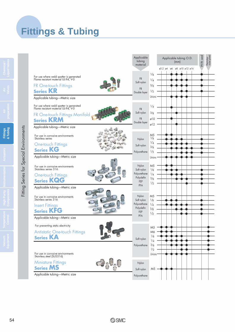
Fittings & Tubing
ø3.2 ø4 ø6 ø8 ø10 ø12 ø16
Nylon
Soft nylon
Polyurethane
M5
Unions
1 8
ø12
ø10
1 43 81 2
FRSoft nylon
FRDouble layer
1 8
1 4
3 8
1 2
Unions
FRSoft nylon 3 8
1 4
FRDouble layer
M5
Nylon
Soft nylon
Polyurethane
Unions
Soft nylon
Polyurethane
1 81 43 81 2
M5M6
Fitti
ng S
erie
s fo
r Spe
cial
Env
ironm
ents
For use where weld spatter is generatedFlame resistant material UL-94, V-0
FR One-touch FittingsSeries KRApplicable tubing—Metric size
For use where weld spatter is generatedFlame resistant material UL-94, V-0
FR One-touch Fittings ManifoldSeries KRMApplicable tubing—Metric size
For use in corrosive environments Stainless series
One-touch FittingsSeries KGApplicable tubing—Metric size
For preventing static electricity
Antistatic One-touch FittingsSeries KA
Applicabletubing
material Electr
oless
nicke
l pla
ted
With
sea
l
Applicable tubing O.D.(mm)
For use in corrosive environments Stainless steel (SUS316)
Miniature Fittings Series MSApplicable tubing—Metric size
NylonSoft nylon
PolyurethanePolyolefin
FEPPFA
M51 81 43 81 2
For use in corrosive environments Stainless series 316
One-touch FittingsSeries KQGApplicable tubing—Metric size
NylonSoft nylon
PolyurethanePolyolefin
FEPPFA
M51 81 43 81 2
For use in corrosive environments Stainless series 316
Insert FittingsSeries KFGApplicable tubing—Metric size
54
Che
mic
al /
Liqu
id V
alve
sA
ir
Valv
esA
ir
prep
arat
ion
Fitt
ings
& T
ubib
gA
ctua
tors
Inst
rum
enta
tion
Hig
h P
urity
C
ompo
nent
sTe
mpe
ratu
re
Con
trol
Vacu
um
Equ
ipm
ent

ø6 ø10 ø12 ø16
Black WhiteRedBlue
YellowGreen
1 core2 cores3 cores
2 cores
3 cores
Black WhiteRedBlue
YellowGreen
Black WhiteRedBlue
YellowGreenClear
Orange
Black WhiteBlue
Translucent
Black WhiteRedBlue
YellowGreenTranslucentYellowbrown
ø "(ø3.2)(ø ") (ø ")
1 85 32
ø45 16
ø8 ø " ø " ø " ø " 3 16 3 8 1 21 4
For flexible and moving applications
Tubi
ng
Polyurethane Coil TubingSeries TCU
General tubing 1.5 MPa max. at 20°C
Nylon TubingSeries T/TIA
Slightly flexible 1.0 MPa max. at 20°C
Soft Nylon TubingSeries TS/TISA
Flexible 0.8 MPa max. at 20°C
Polyurethane TubingSeries TU/TIUB
Extremely flexible 0.6 MPa max. at 20°C
Soft Polyurethane TubingSeries TUS
For flexible multi-tube applications
Polyurethane Flat TubingSeries TFU
0.8 MPa standard type, 1.0 MPa for high pressure type
Hard Polyurethane TubingSeries TUH
Col
or
Tubing O.D.
Metric size (mm) Inch size (inch)ø2
Pneumatic Piping EquipmentE-51-B
55
Che
mic
al /
Liqu
id V
alve
sA
ir
Valv
esA
ir
prep
arat
ion
Fitt
ings
& T
ubib
gA
ctua
tors
Inst
rum
enta
tion
Hig
h P
urity
C
ompo
nent
sTe
mpe
ratu
re
Con
trol
Vacu
um
Equ
ipm
ent

Fittings & Tubing
Black WhiteRedBlue
Green
Black
Black WhiteRedBlue
YellowGreen
Black WhiteRedBlue
YellowGreen
ø6 ø10 ø12 ø19ø "(ø3.2)(ø ") (ø ")
1 85 32
ø45 16
ø8 ø " ø " ø " ø " 3 16 3 8 1 21 4
Tubi
ng
FR Double Layer TubingSeries TRBFlame resistance (Equivalent to UL-94 standard, V-0)
Use in spatter generating atmosphere/Flame resistant material
FR Soft Nylon TubingSeries TRSFlame resistance (Equivalent to UL-94 standard, V-0)
For preventing static electricity
Antistatic Polyurethane TubingSeries TAU
FR Double Layer Polyurethane TubingSeries TRBUFlame resistance (Equivalent to UL-94 standard, V-0)
Col
or
Tubing O.D.
Metric size (mm) Inch size (inch)
Black
For preventing static electricity
Antistatic Soft Polyurethane TubingSeries TAS
Translucent
Outstanding corrosion resistance.
Super PFAHigh Purity Fluoropolymer TubingSeries TL/TIL
Black WhiteRedBlue
YellowGreen
Polyolefin TubingSeries TPH
Clean tubing
Black WhiteRedBlue
YellowGreen
Soft Polyolefin TubingSeries TPS
Clean tubing
Black RedBlue
Translucent
FEP Fluoropolymer TubingSeries TH/TIH
Outstanding corrosion resistance.
ø16 ø "3 4 ø1"
56
Che
mic
al /
Liqu
id V
alve
sA
ir
Valv
esA
ir
prep
arat
ion
Fitt
ings
& T
ubib
gA
ctua
tors
Inst
rum
enta
tion
Hig
h P
urity
C
ompo
nent
sTe
mpe
ratu
re
Con
trol
Vacu
um
Equ
ipm
ent

ø6 ø10 ø12 ø16 ø "(ø3.2)(ø ") (ø ")
1 85 32
ø45 16
ø8 ø " ø " ø " ø " 3 16 3 8 1 21 4
Related Products:
Multi-tube HolderSeries TM
Tube CutterSeries TK
Rela
ted
Prod
ucts
Tube Releasing ToolSeries TG
Tube Stand & Tube Reel Series TB/TBR
Col
our Tubing O.D.
Metric size (mm) Inch size (inch)
Low Torque Metal SealType Rotary JointSeries MQRRo
tary
Join
t
Number of circuits (number of ports): 1, 2, 4, 8, 12, 16
Blow GunSeries VMGBl
ow G
un
Pressure loss is less than 1%.
Nozzles for BlowingSeries KN
Noz
zles
Nozzle system for air blowing and back pressure sensing.
OrangeYellowBlue
Green
Double Layer Tube Stripper Series TKS
Pneumatic Piping EquipmentE-51-B
The outer layer for double layer tubing, Series TRB, TRBU is peeled off easily.
57
Che
mic
al /
Liqu
id V
alve
sA
ir
Valv
esA
ir
prep
arat
ion
Fitt
ings
& T
ubib
gA
ctua
tors
Inst
rum
enta
tion
Hig
h P
urity
C
ompo
nent
sTe
mpe
ratu
re
Con
trol
Vacu
um
Equ
ipm
ent

S Couplers Series KK
Series KK3/4/6
Series KK2
Male thread type
KKH3KKH4
R1/8 R1/4 R3/8 R1/2
Nut fitting type (for fiber reinforced urethane hose)
KKH3KKH4
5/8 6/9 6.5/10 8/12 8.5/12.5
Plug nut fitting type (for fiber reinforced urethane hose)
KK135/8 6/9 6.5/10 8/12 8.5/12.5 11/16
Female thread type
KKH3KKH4
Rc1/8 Rc1/4 Rc3/8
Male thread type
KK2KK3KK4KK6
M5 R1/8 R1/4 R3/8 R1/2 R3/4
One-touch fitting type (Straight/Elbow/Bulkhead)
KK2KK3KK4KK6
Applicable tubing O.D. mmø3.2 ø4 ø6 ø8 ø10 ø12 ø16
Nut fitting type (for fiber reinforced urethane hose)
KK3KK4KK6
Applicable hose I.D./O.D. mm5/8 6/9 6.5/10 8/12 8.5/12.5 11/16
Female thread type
M5Series
KK2KK3KK4KK6
Port sizeRc1/8 Rc1/4 Rc3/8 Rc1/2
Male thread type
KK13R1/8 R1/4 R3/8 R1/2
Barb fitting type
KK131/4" 1/4" 3/8" 1/2"
Female thread type
KK13Rc1/4 Rc3/8 Rc1/2 G1/4
Male/Female thread type
KKA3KKA4KKA6KKA7KKA8KKA9
R·Rc1/8 R·Rc1/4 R·Rc3/8 R·Rc1/2 R·Rc3/4 R·Rc1 R·Rc1 1/4 R·Rc1 1/2
S Couplers with sleeve lock
Series KK
Series
Series
Series
S Couplers without sleeve lock
Series KKH
Stainless steel type
Series KKA
Manufactured by RECTUS AG
Series KK13
Port size
Series Port size
Series
Series
Port size
Port size
Port size
Port size
Series
Series
Series
Series
Series
Applicable hose I.D./O.D. mm
Applicable hose I.D.
Applicable hose I.D./O.D. mm
KKEUS50-19
58
Che
mic
al /
Liqu
id V
alve
sA
ir
Valv
esA
ir
prep
arat
ion
Fitt
ings
& T
ubib
gA
ctua
tors
Inst
rum
enta
tion
Hig
h P
urity
C
ompo
nent
sTe
mpe
ratu
re
Con
trol
Vacu
um
Equ
ipm
ent

Miniaturization of equipment
Space Saving Products series now available for further miniaturisation.
MTS Series
PSE Series
CJ5/CG5 Series
SMAC Series
• Short stroke:Max.stroke:30mm
MXP Series
• Long stroke:Max.stroke:400mm
MXY Series
Mini Free-Mount Cylinder
CUJ Series
MH Series
CRJ Series MSQ Series
• Double rack-and-pinion type• Single rack-and-pinion type
CXSJ Series
Dual Rod Cylinder
MGJ Series
Miniature Guide Rod Cylinder
Air Slide Table Air Slide Table Precision Cylinder
Rotary Actuator Rotary Actuator Stainless Steel Cylinder
Moving Coil Actuators Pressure sensors Air Grippers
59
Che
mic
al /
Liqu
id V
alve
sA
ir
Valv
esA
ir
prep
arat
ion
Fitt
ings
& T
ubib
gA
ctua
tors
Inst
rum
enta
tion
Hig
h P
urity
C
ompo
nent
sTe
mpe
ratu
re
Con
trol
Vacu
um
Equ
ipm
ent

Electric actuators
Electric Cylinders
Series LZLooking for a simple electric cylinder that can be operated like an air cylinder for simple end to end motion? Then the LZ electric cylinder available in two sizes and driven with a 24VDC motor should fit the bill. When used in combination with the LC3 directional control driver which is operated with ON/OFF signals similar to that used for a solenoid valve, cylinder speeds up to 200mm/s and thrust up to 196N are possible. Available with multiple mounting options and strokes up to 200mm this cylinder is the perfect solution for simple applications where there is no compressed air supply.
Basic Specifications
∗ Contact SMC for detailed specifications and how to order
Thrust
Speed
Standard strokes
Motor type
Horizontal mounting:Up to 80 N (LDZ3)Vertical mounting:Up to 40 N (LDZ3L)Horizontal mounting:Up to 196 N (LDZ5)Vertical mounting:Up to 100 N (LDZ5L)
Up to 200 mm/s
25, 40, 100, 200 mm
24 VDC
e-Rodless Actuator
Series E-MY2
Short Stroke Electric Actuators
Series LXF•LXP•LXS
These rodless actuators combine the speed, controllability and performance of an electric actuator with the easy functionality of an air cylinder through the use of a simple and quick three step set-up operation. With a belt driven construction and strokes between 50-1000mm this actuator is capable of velocities up to 1000 mm/sec and 0.5g acceleration. Available in two sizes with either a cam follower guide or high precision type for maximum payloads of 5 or 10kg.
∗ Contact SMC for detailed specifications and how to order
Maximum load weight
Speed
Standard strokes
Motor type
Up to 5 kg (E-MY216)Up to 10 kg (E-MY225)
100 up to 1000 mm/s
100, 200, 300, 400, 500,
600, 700, 800, 900, 1000 mm
Stepper with encoder
Currently available in three compact model types; a low profile slide table (LXF), a guide rod type (LXP) and a slide table version with increased rigidity (LXS). Incorporating either 2 or 5 phases stepper motors, these high performance actuators deliver some really impressive muscle power and can move loads of up to 10kg at speeds up to 200mm/sec. Additionally, they are also highly accurate, with position repeatability of between +/- 0.03 and +/- 0.05 mm dependent on model type.
Maximum work loadSpeed
Standard strokes
Motor type
Up to 3 kg
Up to 200 mm/s
25, 50, 75, 100 mm
Stepper
Maximum work load
Speed
Standard strokes
Motor type
Up to 6 kg (Horizontal mounting)Up to 5 kg (Vertical mounting)
Up to 200 mm/s
50, 75, 100, 125, 150, 175, 200 mm
Stepper
∗ Contact SMC for detailed specifications and how to order
Maximum work load
Speed
Standard strokes
Motor type
Up to 10 kg (Horizontal mounting)Up to 5 kg (Vertical mounting)
Up to 200 mm/s
50, 75, 100, 125, 150 mm
Stepper
Basic Specifications
Basic Specifications Series LXF
Basic Specifications Series LXP
Basic Specifications Series LXS
Simplified Options
60
Che
mic
al /
Liqu
id V
alve
sA
ir
Valv
esA
ir
prep
arat
ion
Fitt
ings
& T
ubib
gA
ctua
tors
Inst
rum
enta
tion
Hig
h P
urity
C
ompo
nent
sTe
mpe
ratu
re
Con
trol
Vacu
um
Equ
ipm
ent

Single Axis Electric Actuator
Series LJ1
Low Profile Single Axis Electric Actuator
Series LG1
Electric Actuator with Integrated
Guide Series LTF
This comprehensive range of electric actuators is available with two types of precise linear guides and three types of feed screws and are also designed for use with our LC8 positioning driver. With high positioning accuracy, dual mounting and multiple cable entry options, these actuator are designed to provide X-Y axis capability and are the perfect solution for pick and place and palletizing operations.
∗ Contact SMC for detailed specifications and how to order
Maximum work loadSpeed
Standard strokes
Motor type
Up to 60 kg
Up to 1000 mm/s
100, 200, 300, 400, 500, 600,
800, 1000, 1200, 1500 mm
AC Servomotor
With its space saving design, this compact electric actuator, with top or bottom mounting options, offers high rigidity and high linear precision guide control. Designed for use with our latest Series LC8 Positioning Driver for AC servomotors, these actuators offer excellent accuracy and high production flexibility.
∗ Contact SMC for detailed specifications and how to order
Maximum work load
Speed
Standard strokes
Motor type
Up to 30 kg
Up to 1000 mm/s
100, 200, 300, 400, 500, 600,700, 800, 900, 1000, 1200 mmAC Servomotor
This light weight and compact actuator is the result of designing an integrated linear guide into the support frame to form a one piece structure. Additionally the circulating type ball bearing liner guide and martensitic stainless steel frame creates a table with high rigidity and high sliding accuracy. Available in two sizes with 100 & 200W AC servomotors for use with the LC8 positioning driver, this actuator is perfect for use in high performance applications wanting a space saving design.
∗ Contact SMC for detailed specifications and how to order
Maximum work load
Speed
Standard strokes
Motor type
Up to 50 kg
Up to 1000 mm/s
100, 200, 300, 400, 500, 600,700, 800, 900, 1000 mmAC Servomotor
Basic Specifications
Basic Specifications
Basic Specifications
More Advanced Options
Positioning Driver (for AC servomotor)
Series LC8• Up to 117 programmable positioning steps can be
operated using I/O from a PLC.• All system parameters can be set using an easy to
use Windows® based software.• Up to 6 slave units can be attached for multi-axis
systems.• For use with Series LJ1, LG1 and LTF electric
actuators.
E-MY2EUS100-51
LXEMC-LX/LC6D-01
LC8/LJ1/LG1/LTFEUS10-53
61
Che
mic
al /
Liqu
id V
alve
sA
ir
Valv
esA
ir
prep
arat
ion
Fitt
ings
& T
ubib
gA
ctua
tors
Inst
rum
enta
tion
Hig
h P
urity
C
ompo
nent
sTe
mpe
ratu
re
Con
trol
Vacu
um
Equ
ipm
ent

Electro-Pneumatic Pressure Regulator Series ITVStepless control of air pressure proportional to an electrical signal
0.2 kPa (100kPa specification)
Within ±1% (F.S.)
Within ± 0.5 % (F.S.)
Series ITV30004000 l /min(ANR)
Controller for electro-pneumaticpressure regulator Series ICDigital signal is converted to analog signal.
Series ITV00007 l /min(ANR) IP65
Parts in contact with fluids are oil free.
Residual pressure is Zero with no electrical signal.
CE (Series ITV0000/1000/2000/3000)
Equivalent to IP65
Sensitivity:
Linearity:
Hysteresis:
∗Pressure range 0.9MPa Supply pressure 1.0MPa
Series ITV1000200 l /min(ANR) ∗
Series ITV20001500 l /min(ANR) ∗
∗
∗
62
Che
mic
al /
Liqu
id V
alve
sA
ir
Valv
esA
ir
prep
arat
ion
Fitt
ings
& T
ubib
gA
ctua
tors
Inst
rum
enta
tion
Hig
h P
urity
C
ompo
nent
sTe
mpe
ratu
re
Con
trol
Vacu
um
Equ
ipm
ent

Model Pressure range Input OutputCo
ntro
ller
Series IC
IC1
IC3
IC5
IC9
10 bit parallel input
4 points inputs
0.1MPa
0.5MPa
0.9MPa
-0.1MPa
0~10VDC
4~20mADC
Series Model Set pressure range Sensitivity Accuracy
Series ITV0000
Series ITV1000
Series ITV2000
Linearity
Within ±1% F.S.
Hysteresis
Within ±0.5% F.S.
With guard function for supply pressure / ITV1000,2000,3000
Detection pressure 100±80kPa/ITV1000,2000,3000
Detects drop of supply pressure
Idle operation of solenoid valve is stopped and pressure at secondary side is exhausted.
Electro
-pn
eum
atic pressu
re regu
lator
0.001~0.1MPa
0.001~0.5MPa
0.001~0.9MPa
-1~-100KPa
0.005~0.1MPa
0.005~0.5MPa
0.005~0.9MPa
0.005~0.1MPa
0.005~0.5MPa
0.005~0.9MPa
-1.3~-80kPa
0.005~0.1MPa
0.005~0.5MPa
0.005~0.9MPa
ITV001
ITV003
ITV005
ITV009
ITV101
ITV103
ITV105
ITV201
ITV203
ITV205
ITV209
ITV301
ITV303
ITV305
0.2kPa
1.0kPa
1.8kPa
0.2kPa
0.2kPa
1.0kPa
1.8kPa
0.2kPa
1.0kPa
1.8kPa
0.16kPa
0.2kPa
1.0kPa
1.8kPa
Series ITV3000
Note) Only 4 to 20mA input signal option available at this time. No monitor voltage output available.
Digital signal is converted to analog signal.
4000 l /min(ANR)*
1500 l /min(ANR)*
200 l /min(ANR)*
7l /min(ANR)*
•Parts in contact with fluids are oil free.•Residual pressure is Zero with no electrical signal.
* Pressure range 0.9MPa Supply pressure 1.0MPa
Made to Order
ITV0000ES60-17
ITVES60-15
63
Che
mic
al /
Liqu
id V
alve
sA
ir
Valv
esA
ir
prep
arat
ion
Fitt
ings
& T
ubib
gA
ctua
tors
Inst
rum
enta
tion
Hig
h P
urity
C
ompo
nent
sTe
mpe
ratu
re
Con
trol
Vacu
um
Equ
ipm
ent

Digital pressure SwitchSeries Variations
Hysteresis mode: Variable
Window comparator mode: Variable
–0.1 to 1 MPa10 to –101 kPa
–100 to 100 kPa–10 to 100 kPa
–50 to 500 kPa–0.2 to 2 kPa
–0.1 to 1 MPa10 to –101 kPa–101 to 101 kPa–10 to 100 kPa
NPN/PNP open collector 2 outputs
Analog output
NPN/PNP open collector 1 CH: 2 outputs
2 to 4 CH: 1 output each
2 colour
±0.1% F.S. or less
±0.5% F.S. or less(0 to 50°C)
Sensor input amount:1 input
Controller
12 to 24 VDC (Ripple p-p 10% or less)
IP40
Push-button calibration
Hysteresis mode: Variable
Window comparator mode: Fixed (3 digits)
Front only IP65The rest IP40
Panel mounting possibleSelectable pressure unitAuto shift function Auto preset function
Display calibration functionAnti-chattering functionPeak holdBottom hold
PSE300 PSE200
0 to 1 MPa0 to –101 kPa0 to 101 kPa
–101 to 101 kPa
±1% F.S. or less
General pneumatic General pneumaticGeneral fluids
0 to 1 MPa0 to –101 kPa
–100 to 100 kPa
IP40IP65
±0.2% F.S. or less
Set pressure range
Repeatability
Calibration method
Fluid
Temperature characteristics
Model
Hysteresis
Output
Display(Resolution)
Enclosure
Note
Voltage
Sensor
12 to 24 VDC (Ripple p-p 10% or less)
IP40
±2% F.S. or less(25°C)
0 to 1 MPa0 to –101 kPa
–100 to 100 kPa0 to 500 kPa
±2% F.S. or less(0 to 50°C: based on 25°C)
±3% F.S. or less(–10 to 60°C: based on 25°C)
±0.3% F.S. or less
±3% F.S. or less(25°C)
PSE53 PSE54 PSE56 PSE550
Individual sensor and controller type
Sensor input amount:4 input
PSEEUS100-56
0 to 2 kPa(and specials)
1 to 5 V 1 to 5 V 4 to 20 mA
1 colour
64
Che
mic
al /
Liqu
id V
alve
sA
ir
Valv
esA
ir
prep
arat
ion
Fitt
ings
& T
ubib
gA
ctua
tors
Inst
rum
enta
tion
Hig
h P
urity
C
ompo
nent
sTe
mpe
ratu
re
Con
trol
Vacu
um
Equ
ipm
ent

Integrated sensor and controller type
Set pressure range
Repeatability
Calibration method
Fluid
Temperature characteristics
Model
Hysteresis
Output
Display(Resolution)
Enclosure
Note
Voltage
±3% F.S. or less(0 to 50°C: based on 25°C)
±2% F.S. or less(0 to 50°C: based on 25°C)
ZSE30: ±0.2 F.S. ±2 digits or lessISE30: ±0.2 F.S. ±1 digit or less ±0.2% F.S. ±1 digit or less
Hysteresis mode: VariableWindow comparator mode: Fixed (3 digits)
Digit is min. calibration unit.
NPN/PNP, 2 outputsopen collector Analog output
General fluids
Push-button calibration
0.4 to 10 MPa0.5 to 15 MPa
–100 to 100 kPa–0.1 to 1 MPa0 to 1 MPa
–100 to 100 kPa10 to –101.3 kPa
–0.1 to 1 MPa
–101 to 101 kPa–0.1 to 1 MPa
Red LED (1 colour)
IP65 IP67IP40
NPN/PNP, 1 outputopen collector 1-5 V, 4-20 mAAnalog output
Red/Green LED(2 colour)
Panel mounting possibleSelectable pressure unit
Panel mounting possibleSelectable pressure unitAuto shift functionCompound pressure
Selectable pressure unit R threadPanel mounting possibleSelectable pressure unitAuto shift function
URJTSJPanel mounting possibleSelectable pressure unitAuto shift function
Hysteresis mode: Variable
Window comparator mode: Variable
ZSE50/60F: ±0.2% F.S. ±1 digit or lessISE50/60: ±0.3% F.S.±0.5% F.S.
1 setup NPN/PNPopen collector
PNP open collector
NPN/PNP, 2 outputsopen collector Analog output
Hysteresis mode: Variable
Window comparator mode: Variable
Hysteresis mode: Variable
Window comparator mode: Fixed (3 digits)
Digit is min. calibration unit.
ZSE60FISE60
ZSE50FISE50
ISE75ISE75HISE70
ZSE40ISE40
ZSE30ISE30
General pneumatic
12 to 24 VDC (Ripple ±10% or less)
ZSEISE50/60ES100-43
ISE70/75/75HES100-52
ZSEISE40P-E99-1
ZSEISE30ES100-42
Red/Green LED(2 colour) Red LED (1 colour)
IP65
65
Che
mic
al /
Liqu
id V
alve
sA
ir
Valv
esA
ir
prep
arat
ion
Fitt
ings
& T
ubib
gA
ctua
tors
Inst
rum
enta
tion
Hig
h P
urity
C
ompo
nent
sTe
mpe
ratu
re
Con
trol
Vacu
um
Equ
ipm
ent

Digital Flow SwitchSeries Variations
1
2
4
3
1
2
4
3
• Copy functionPossible to copy information
from one channel to one or more other channels.
• Key lock function
• Unit switching function
• Peak value and lowest value holding
• Channel scan function Allows constant monitoring of the displayed pressure value for each channel.
Sensor connector
Power supply/Output connector
CONNECTOR
No tools required!
CH1
CH2
CH3
CH4
copycopy
copy
Copying CH1 setting to CH2, 3 and 4.
MULTI COUNTER:CEU5 A COM COM COMB DC12V GND F.G. R.S. HOLD BANK1 BANK2
COM S.STOPOUT1OUT2OUT3OUT4OUT5AC100~240V
COUNT PRESET FUNC.
SD SGRD RS-232C
UP
LEFT RIGHT
DOWN
SEL. SETMODE
M/C
M/C
M/C
The accumulated pulse outputfunction enables remote monitoring of accumulated flow.
Main line flow control
Flow control for each branch line
Pulse counter
(Refer to page 36.)
Clean gas filter
Set the clean gas filter on the outlet side
piping of the flow switch.
Flow control of N2 gas to prevent detection camera shimmering and lead frame oxidation
Flow control of cooling water for wafer temperature regulation and high frequency power supply
Flow control of pressurized cooling water for welding gun
Makes it possible to monitor the air flow from the main line to each branch line.
Application Examples
Flow rate setting and monitoring are possible with the digital display.
Two types are available: Integrated and Remote type.
Three types of output: Switch, accumulated pulse, and analog outputs.
Switching from real-time flow rate to accumulated flow is possible.
Two independent flow rate settings are possible.
Water resistant construction conforming to IP65
Connection
Function
• 4 independent flow rate ranges can be monitored by a single controller.
A single controller can monitor the flow rate of 4 different sensors.
PF2DES100-50
PF2A/WES100-48
PFMES100-63
66
Che
mic
al /
Liqu
id V
alve
sA
ir
Valv
esA
ir
prep
arat
ion
Fitt
ings
& T
ubib
gA
ctua
tors
Inst
rum
enta
tion
Hig
h P
urity
C
ompo
nent
sTe
mpe
ratu
re
Con
trol
Vacu
um
Equ
ipm
ent

1
2
4
3
1 to 105 to 50
10 to 10020 to 20050 to 500
150 to 3000300 to 6000600 to 12000
PF2A710PF2A750PF2A711PF2A721PF2A751PF2A703HPF2A706HPF2A712H
Flow rate measurementrange l/min Integrated type Display unit
PF2W30
PF2W33
Sensor unit
PF2W504(T)PF2W520(T)PF2W540(T)PF2W511
Display unit (4ch)
PF2W200.5 to 42 to 165 to 40
10 to 100
PF2W704(T)PF2W720(T)PF2W740(T)PF2W711
Flow rate measurementrange l/min Display unit
PF2D30
Sensor unit
PF2D504PF2D520PF2D540
Display unit (4ch)
PF2D200.4 to 4
1.8 to 204.0 to 40
Display unit
PF2A30
PF2A31
—
Flow rate measurementrange l/min Integrated type
Remote type
Remote type
Remote type
Sensor unitPF2A510PF2A550PF2A511PF2A521PF2A551
—
Display unit (4ch)
PF2A20
—
For Air
Series PF2A
For Water
Series PF2W
For Deionized Water and Chemicals
Series PF2D
Compact 2-color Display Digital Flow Switch
Series PFM
Flow rate measurementrange l/min Integrated type
0.2 to 10 (0.2 to 5)0.5 to 25 (0.5 to 12.5)
1 to 50 (1 to 25)2 to 100 (2 to 50)
PFM710PFM725PFM750PFM711
( ): In the case of CO2
67
Che
mic
al /
Liqu
id V
alve
sA
ir
Valv
esA
ir
prep
arat
ion
Fitt
ings
& T
ubib
gA
ctua
tors
Inst
rum
enta
tion
Hig
h P
urity
C
ompo
nent
sTe
mpe
ratu
re
Con
trol
Vacu
um
Equ
ipm
ent

Ionizer with surface potential sensorSeries IZS30
Power consumption: 4 W while eliminating static electricity, 2.5 W while standing by (When a surface potential sensor is used.)
• Automatically stops generating ions when the static electricity has been eliminated.• Automatically controls the generation of ions and turns the compressed air on/off
depending on the existence of a charged material. (When a retrofitted solenoid valve is controlled by using the output signal of an ionizer.)
Mode
Sensing DC mode(with sensor)
Pulse DC mode(without sensor)
Continuously emits ions of reversed polarity to charged objects as a result of feedback from the external sensor. (Mode changes to pulse DC mode when a sensor is not used.)
Ion emission image
Conditions / Static buildup decreased from 3000 V to 300 V
Discharged object: Charged plate (150 mm x 150 mm, Capacitance 20 pF)
Installation distance: Tungsten electrode with air purge 200 mm from work piece
Discharge time 0.3 seconds
A charged object image
Ionizer/ with surface potential sensor
3
2
1
0
-1
-2
-3
1 2 3 4Time sec.
Cha
rge
volta
ge o
n w
ork
piec
e k
V
With sensor
Without sensor
With sensor
Without sensor
<Conditions>Height when installed: 250 mmAir purge: 20 l/min (ANR)Electrostatic charged plate: 150 mm x 150 mm, 20 pFOperating frequency without sensor: 33 Hz
Action
Continuously emits ions of reversed polarity to charged objects as a result of feedback from the external sensor.
Alternatively emits positive and negative ions.
How to use
Can eliminate static electricity depending on the charged status of the material. Suited for a rapid elimination of static electricity.
Suited for a continuous material such as a sheet of film and/or for eliminating static electricity in a specific space.
Positive and negative electric charge on a work piece is measured and neutralized by a continuous flow of ions.
68
Che
mic
al /
Liqu
id V
alve
sA
ir
Valv
esA
ir
prep
arat
ion
Fitt
ings
& T
ubib
gA
ctua
tors
Inst
rum
enta
tion
Hig
h P
urity
C
ompo
nent
sTe
mpe
ratu
re
Con
trol
Vacu
um
Equ
ipm
ent

0 500 1000 1500 2000Installation distance [mm]
Dis
char
ge ti
me
[sec
.]
The effects of installation distance is reduced.
One-touch fitting with check valve(both ends: standard equipment)
Controller, Built-in high voltage power supply
ModelTypeBar lengthIon generation methodVoltage applied methodOutput for emitting electricityIon balance Note 1)
Air purge
Power supply voltage
Current consumption
Input signal
Output signal
Operating ambient temperatureOperating ambient humidityMaterialVibration resistanceShock resistanceWeight
IZS30-1260Bar type1260 mm
Corona discharge typePulse DC method
±6000 V±30 V or less
Air (clean and dry)85 l/min (ANR)0.7 MPa or less
ø421.6 V DC to 26.4 V DC
150 mA or less100 mA or less100 mA or less
NPN transistor (open collector), or contact signal with no voltage
FET (open drain), 28 V DC, 100 mA or less
0 to°50C35 to 80% Rh (non-condensing)
Cover of ionizer: ABS, Electrodes: Tungsten, Sensor body: Aluminum alloyDurability 50 Hz Amplitude 1 mm XYZ each 2 hours
10 G1100 g
IZS30-300
300 mm
20 l/min (ANR)
330 g
IZS30-780
780 mm
50 l/min (ANR)
710 g
IZS30-1500
1500 mm
110 l/min (ANR)
1410 g
IZS30-1900
1900 mm
140 l/min (ANR)
1930 g
Operating fluidAir supply flow rate Note 2)
Operating pressureConnecting tube O.D.
Sensor mode while eliminating static electricity
Sensor mode while standing byPulse DC modeSuspension of eliminating static electricity
High voltage errorSensor errorCompletion of eliminating electricity
Specifications
Electrodes are supplied in a cartridge.
Note 1) With air purge and installation distance of 300 mm. Note 2) The minimum flow rate that can eliminate electricity between a charged object and an ionizer at a distance of 2000 mm.
Without sensor
With sensor
25
20
15
10
5
0
Installation distance and discharge time (air purged) Air purged flow rate: (20 l/min ANR) Frequency of operation (without sensor): 33 Hz
Discharged work pieceCharged voltage: Time for 3000 V down to 300 V or lessCharged object: 150 x 150 mm (20 pF)
Ionizer
Work piece
Inst
alla
tion
dist
ance
Surface potential sensor Measures the polarity of a charged object, as well as the amount of charged electricity.
One-touch electrode replacement.
Feedback control by the external sensor reduces the time needed for eliminating static electricity, compared to use without a sensor.
IZS30ES100-57
69
Che
mic
al /
Liqu
id V
alve
sA
ir
Valv
esA
ir
prep
arat
ion
Fitt
ings
& T
ubib
gA
ctua
tors
Inst
rum
enta
tion
Hig
h P
urity
C
ompo
nent
sTe
mpe
ratu
re
Con
trol
Vacu
um
Equ
ipm
ent

Special diaphragm construction insures gentle opening and closing that prevents the formation of micro-bubbles.
In addition to a body designed for smooth flow with minimal internal dead space, integral fittings eliminate the possibility of residual liquid in pipe threads.
Compatible with chemicals such as acids, bases and ultra DI water.
A unique guide ring on the piston rod eliminates lateral motion of the poppet, greatly increasing seal life and reducing particle formation with a stable work surface.
Eliminates problems due to over tightening• Special locking mechanism• High flexural strength (tubing supports)
A bumper absorbs piston momentum to minimize impact-induced particles.
The diaphragm is supported by a buffer that minimizes deformation, which gives it long life and resistance to back-pressure.
LVCLVCLVC LVALVALVA LVHLVHLVH
Foodprocessing
Cleaningequipment
IC manu-facturing
AnalyticalInstruments
For shut off
For airbleeding
ChemicalsMedical
Medicalequipment
Cleaningequipment
Pharma-ceutical manu-
facturing
AnalyticalInstruments
ChemicalsIC manu-facturing
lines
Back-pressure resistance and long life Buffer
Different tubing sizes can be selected Hyper fitting
Stable Sealing Surface Guide ring
Low particle generation Piston bumper
Prevents Micro-Bubbles Diaphragm (PTFE)
Minimal dead space
Outstanding corrosion resistance Body (New PFA)
High Purity Chemical Valve Series LV
Main applications and fields
70
Che
mic
al /
Liqu
id V
alve
sA
ir
Valv
esA
ir
prep
arat
ion
Fitt
ings
& T
ubib
gA
ctua
tors
Inst
rum
enta
tion
Hig
h P
urity
C
ompo
nent
sTe
mpe
ratu
re
Con
trol
Vacu
um
Equ
ipm
ent

Integral Fittings
Series LVC
LVCLVC LVALVA LVHLVH
N.C./N.O. with same configuration/Double acting.
Compatible with 100°C fluid temperature.
Body material: New PFA
Locking and non-locking types available.
Integral fitting type/Threaded type.
Body material: New PFA /Stainless steel/PPS
Compact type is introduced as a new series to complement conventional Series LVC with integral fittings.
Mounting base dimensions conform to SEMI Standard, F65-1101. (Except for LVD10)
Dimension across inlet/outlet ports: Reduced by up to 29%.
Body : New PFA / Diaphragm: PTFE /
Actuator section: PPS
Threaded Ports
Series LVA
Manual Operation
Series LVH
Compact type
Series LVD
Diaphragm material PTFE, EPR, NBR are selectable.
Body material: New PFA /Stainless steel/PPS
Integral Tubing(construction)
3 port added
3 port added
LVC/LVA/LVHES70-16
LVDES70-24
71
Che
mic
al /
Liqu
id V
alve
sA
ir
Valv
esA
ir
prep
arat
ion
Fitt
ings
& T
ubib
gA
ctua
tors
Inst
rum
enta
tion
Hig
h P
urity
C
ompo
nent
sTe
mpe
ratu
re
Con
trol
Vacu
um
Equ
ipm
ent

HYPER FITTING® / LQ1•LQ2•LQ3High Purity Fluoropolymer Fittings & Tubing
Series LQ1•LQ2SMC high purity series responding to the latest demands in process control
LQ Series12
Series LQ3Collet Type/LQ3
New PFAmaterial
21
43
Tubing
Nut Insert bushing
Main seal
Main seal
Body
A seal lock provided for the nut to prevent loosening, and trapezoidal screw threads tightened at a high torque provide a construction with high seal integrity even when subjected to heat cycles.
A tubing support on the nut provides strong resistance to bending and resist crimping deformation of tubing.
Reducer type: The tubing size can be changed by replacing the nut and the insert bushing on the same body.
Tightening to the end surface plus an additional 1/8 turn simplifies confirmation procedure and eliminates the need of tightening torque control.
Close adhesion of fittings and tubing facilitates excellent flow through characteristics with minimal liquid residual
The nut can be easily assembled into the fitting bodywith no need of alignment. Triple sealing: The triple sealing construction consisting of
double sealing in the axial direction and single sealing in thecircumferential direction prevents liquid leakage.
Tubing supports:Strong resistance to tube bending anddeformation.
Locking: 2 stage pressing construction of the Collet end ensuressealing and tube locking. The cylindrical part is also provided withthe tube locking mechanism. Improved sealing and tube retention.
Improved flow-through characteristics:Excellent flow-through characteristics are achieved by minimizing liquid deposit.
Locking:Trapezoidal thread that withstands heat stress prevents oblique nut insertion.
Quadruple seal constructionOur new patented high-performance quadruple seal construction, as well as our precision insertion tooling provide maximum leak protection in your process circuitry.
LQES70-17
72
Che
mic
al /
Liqu
id V
alve
sA
ir
Valv
esA
ir
prep
arat
ion
Fitt
ings
& T
ubib
gA
ctua
tors
Inst
rum
enta
tion
Hig
h P
urity
C
ompo
nent
sTe
mpe
ratu
re
Con
trol
Vacu
um
Equ
ipm
ent

Material: Super PFA Material: FEP
Series ShapeSize
1/4" 3/8"None 1/8" 1/2" 3/4" 1" ø6 ø8 ø10 ø12 ø19 1/8" 1/4"3/16" 3/8" 1/2" 3/4" 1"ø25
Port sizeTube O.D.
Metric size Inch size
ø4ø3
Connector
LQ H
Male
Female
Male
Female
Male
Female
Male
Female
LQ Series
Elbow
LQ L
Run tee
LQ R
Branch tee
LQ B
Union tee
LQ T12
Panel mount union
LQ P12
Union
LQ U12
Union flange
LQ1F
1
2
3
4
5
6
1
2
3
4
5
6
_
_
_
_
_
_
_
_
_
_
_
_
_
_
_
_
_
_
_
_
_
_
_
_
_
_
_
_
_
_
_
_
_
_
_
_
_
_
_
_
_
_
_
_
_
_
_
_
_
_
_
_
_
_
_
_
_
_
_
_
_
_
_
_
_
_
_
_
_
_
_
_
_
_
_
_
_
_
_
_
_
_
_
_
_
_
_
_
_
_
_
_
_
_
_
_
_
_
_
_
_
_
_
_
_
_
_
_
_
_
_
_
_
_
_
_
_
_
_
_
_
_
_
_
_
_
_
_
_
_
_
_
_
_
_
_
_
_
_
_
_
_
_
_
_
_
_
_
_
_
_
_
_
_
_
_
_
_
_
_
_
_
_
_
_
_
_
_
_
_
_
_
_
_
_
_
_
_
_
_
_
_
_
_
_
_
_
_
_
_
_
_
_
_
_
_
_
Note 1) Standard size With Reducer Note 2) The union flange is only available with LQ1 (Size 4, 5, 6).
12
12
12
12
12
Union elbow
LQ E12
: Only for series LQ1 : Common to series LQ1 and LQ2LQ Series 12
Series TL,TILFluoropolymer tubing
Series TH,TIHFEP tubing
Item
Maximum operating pressure(at 20oC)
Operating temperature
Applicable tubing size
ModelLQ110 LQ120 LQ130 LQ140 LQ150 LQ160 LQ220 LQ230 LQ240 LQ250
0.7MPa
0 to150°C
mm size
inch size
ø3 to ø25
1/8"~1"
1.0MPa
0 to 200°C
ø4 to ø19
1/8"~3/4"
LQ1 Series LQ2 Series
73
Che
mic
al /
Liqu
id V
alve
sA
ir
Valv
esA
ir
prep
arat
ion
Fitt
ings
& T
ubib
gA
ctua
tors
Inst
rum
enta
tion
Hig
h P
urity
C
ompo
nent
sTe
mpe
ratu
re
Con
trol
Vacu
um
Equ
ipm
ent

Custom design temperature control and cooling water related equipment
Temperature setting range: –20°C to 40°C / –20°C to 90°C
Cooling capacity:1kW to 15kW
Temperature stability: ±0.1°C
Types of circulating fluids: Fluorinated fluids, Ethylene glycol aqueous solution∗Contact us for other types of fluids (deionized water, water).
Built-in flow meter for circulating fluid
International standards: ∗Plan to be UL approved.
SEMATECHS2-93, S8-95
SEMI StandardS2-0703, S8-0701, F47-0200, ,
Thermo-chiller
Series HRZA device for circulating a fluid with a constant temperature (High performance type)
Main tank capacity: 12l, 15l, 22l Reduced by 40% (compared with the conventional model)
Circulating fluid recovery tank: 15l to 17lEffortless circulating fluid recovery during maintenance. The working time can be reduced.
Return of circulating fluid
Circulating fluiddischarged
PumpPump
Main tank
Purge port for recovery
OptionCirculating fluid recovery tank Circulating fluid recovery tank Circulating fluid recovery tank
qNormal operation
PumpPump
Main tank
Purge port for recovery
eFluid returns to the main tank from thecirculating fluid recovery tank.
wRecovery of circulating fluidPurge air
Purge air
PumpPump
Main tank
Purge port for recovery
OptionOption
Use
r's e
quip
men
t
Use
r's e
quip
men
t
Use
r's e
quip
men
t
Unique double layer tank structure
Thermo-cooler
Series HRGControls circulating water at a constant temperature
Temperature stability: ±0.5°C, ±1.0°C (Selectable from 2 standards)
Cooling capacity: 1.1kW, 2.3kW, 4.8kW (at 60Hz)
Set temperature: ±5~35°C
Useful for a wide variety of industries: from General to Semiconductor.
Thermal load
74
Che
mic
al /
Liqu
id V
alve
sA
ir
Valv
esA
ir
prep
arat
ion
Fitt
ings
& T
ubib
gA
ctua
tors
Inst
rum
enta
tion
Hig
h P
urity
C
ompo
nent
sTe
mpe
ratu
re
Con
trol
Vacu
um
Equ
ipm
ent

Thermo-con
Series HECCirculator Electronic Cooling / Heating Type
Temperature stability: ±0.01°C to 0.03°C
Set temperature range: 10°C to 60°C
Cooling capacity (with water): 600W, 1200W
Type of circulating fluid: Water, Fluorinated chemicals
International standards: Plan to acquire , UL standards
This originally developed heat exchanger achieves a large cooling capacity with a compact body.
Fluorinated chemicals (GALDEN® HT135, FluorinertTM FC-77) compatible with a standard model.
Thermostatic Bath
Series HEBConstant Temperature Bath Electronic Cooling / Heating Type
set temperature range: –15°C to 60°C
Temperature stability: ±0.1°C (Set temperature 10 to 35°C / including temperature distribution)
Type of constant temperature fluid: Water, Fluorinated chemicals
International standards: Plan to acquire , UL standards
Thermo-module can be operated efficiently.
Low temperature distribution is achieved by stirring fluid up-and-down and around the tank.
Accurate display by measuring the constant temperature fluid with a temperature sensor directly
Temperature control peripherals
Our most suitable products for circulating liquid and cooling lines used in temperature control equipment
SRHClean regulator
ISE50Pressure switch remote type
PF2WDigital Flow switch
VCW•VDWDirect operated2 port valve
Plug valve forcirculating fluid
FGH/FQ1Filters
Thermal loadThermal load
Cooling water line (Plant side)
Thermal load
KKAS coupler
TH•TIHFEP Tubing(Fluororesin)
Circulating liquid line
HRGES40-45
HRZES40-48
75
Che
mic
al /
Liqu
id V
alve
sA
ir
Valv
esA
ir
prep
arat
ion
Fitt
ings
& T
ubib
gA
ctua
tors
Inst
rum
enta
tion
Hig
h P
urity
C
ompo
nent
sTe
mpe
ratu
re
Con
trol
Vacu
um
Equ
ipm
ent

Vacuum Equipment
Air suction filter
Series ZFA
Model Port size Recommended air flow (l/min (ANR)) Weight (kg)
50 0.14200 0.19
ZFA 100ZFA 200
1 81 4
Fluid Air/Nitrogen–100 to 0 kPa
0.5MPa5 to 60°C
30µm0.15MPa
Operating pressure rangeProof pressureOperating temperature rangeFiltrationElement differential pressure resistance
Model
Specifications
Metric size
Inch size
Recommendedair flow l/min (ANR)
Weightg
Port size (Applicable tube O.D.)IN side, OUT side
ø4 10 2220 2230 3050 3075 3975 3920 2220 2230 3075 40100 62
ø6ø6ø8ø8ø10ø3/16"
ø1/4"
ø1/4"
ø3/8"
ø1/2"
Model
ZFB100-04ZFB100-06ZFB200-06ZFB200-08ZFB300-08ZFB300-10ZFB101-05ZFB101-07ZFB201-07ZFB301-11ZFB401-13
Model
Fluid Air/Nitrogen–100 to 0 kPa
0.5MPa0 to 60°C (Non-freezing)
30µm0.15MPa
Nylon/Soft Nylon/Polyurethane
Operating pressureProof pressureOperating and ambient range
Element differential pressure resistanceApplicable tube material
Specifications
Filtration
Air suction filter
Series ZFB
Air suction filter
Series ZFC
Model
ZFC050-02ZFC050-23ZFC050-04ZFC100-04ZFC100-06ZFC200-06ZFC200-08ZFC051-01ZFC051-03ZFC101-03ZFC101-07ZFC201-07ZFC201-09
Port size (Applicable tubing O.D.) Recommended flow rate (l/min (ANR))
Weight(g)IN side, OUT side
ø2ø3.2ø4ø4ø6ø6ø8
ø1/8"ø5/32"ø5/32"ø1/4"ø1/4"ø5/16"
27
1010203050
71010203050
4.9
4.3
11.5
21.5
4.3
11.5
21.5
Metric size
Inch size
Note) Flow rate when the initial pressure drop is 3 kPa or less.
Model
Air, Nitrogen–100 to 0 kPaMax. 0.5 MPa
0 to 60°C (No freezing)10 µm
[ZFC10, 20] 0.15 MPa [ZFC05] 0.10 MPa
FluidOperating pressureVacuum release pressureOperating and ambient temperature rangeFiltrationElement differential pressure resistance
Specifications
Prevents vacuum equipment trouble due to airborne contaminants.
Space saving
Installation and removal are easy with One-touch fittings
Cartridge type with replaceable element
76
Liqu
id
Valv
esA
ir
Valv
esA
ir
prep
arat
ion
Fitt
ings
& T
ubib
gA
ctua
tors
Inst
rum
enta
tion
Hig
h P
urity
C
ompo
nent
sTe
mpe
ratu
re
Con
trol
Vacu
um
Equ
ipm
ent

Vacuum Ejector, In-line type
Series ZUSpace-saving ejector that can be installed in-line with the piping
6mm fittings to connect into pipework.
Integrated exhaust.
Very lightweight and compact.
Choice of 2 nozzle diameters and 2 vacuum levels.
Compact Vacuum Ejector
Series ZA
SUP
EXH
VAC
Body
One-touch fitting One-touch fitting
Diffuser
Manifold
Single unit
General Specifications
Maximum operating pressure
Minimum operating pressure
Proof pressure
Operating temperature range
Operating fluid
Power consumption
0.5 MPa
0.2 MPa
0.6 MPa
5 to 50 °C (No condensation)
Air
0.5W (With power-saving circuit), 1W (Standard)
Ejector Specifications
Nozzle diameter (mm)
Standard supply pressure
Maximum vacuum pressure
Maximum suction flow (l/min (ANR))
Air consumption (l/min (ANR))
0.5
0.40MPa
–74kPa
4
12
0.7
0.45MPa
–78kPa
8
25
2 kinds of pressure range are selectable.
0 to –101kPa
–100 to 100kPa
Release valve N.C.
Supply valve N.C.
Latching
Suction filter Filtration : 30 µm
Available with or without pressure sensorTotal width
Total height
Total length
Weight 50 g
72.9 mm 9.9 mm
52.5 mm
ZAES100-55
ZFCE832
77
Che
mic
al /
Liqu
id V
alve
sA
ir
Valv
esA
ir
prep
arat
ion
Fitt
ings
& T
ubib
gA
ctua
tors
Inst
rum
enta
tion
Hig
h P
urity
C
ompo
nent
sTe
mpe
ratu
re
Con
trol
Vacu
um
Equ
ipm
ent

Vacuum regulatorSeries IRV
Standard
SMC
PUSH L OCK
VAC SET
Rear pressure gauge mounting
SMC
P
USHLOCKVAC SET
Pressuregauge
Pressuregauge
Panel mounting capability is standard
Applications
Lifting of work pieces Leak tester
Vacuum pump
IRVFilter
Solenoid valve
Solenoid valve
Work piece
Pressure converter
Vacuum pump Tank
IRVFilter
Solenoid valve
Suction pad
Work piece
With a single pressure
Vacuum pump
IRV
Filter
Solenoid valve
Suction pad
Work piece
With multiple pressures
Tank
3 sizesoffered in the series
Compact
Light weight
60 l/min (ANR) Note)
100 l/min (ANR) Note)
150 l/min (ANR) Note)
35mm
66mm
120g
270g
700g
Variations have been expanded to three sizes from only one in the previous series T203.Selection is possible to accommodate the applicable flow rate.Note) Flow rate corresponds to
VAC pressure of –101kPa, SET pressure of –80kPa, and initial flow rate setting of 0l/min(ANR).
Front
Back
50mm
(Vacuum pumpside)
(Pad side)
(Vacuum pumpside)
(Pad side)
Pressure gauge can be mounted from the front or rear
ZFCE832
78
Liqu
id
Valv
esA
ir
Valv
esA
ir
prep
arat
ion
Fitt
ings
& T
ubib
gA
ctua
tors
Inst
rum
enta
tion
Hig
h P
urity
C
ompo
nent
sTe
mpe
ratu
re
Con
trol
Vacu
um
Equ
ipm
ent

79
Che
mic
al /
Liqu
id V
alve
sA
ir
Valv
esA
ir
prep
arat
ion
Fitt
ings
& T
ubib
gA
ctua
tors
Inst
rum
enta
tion
Hig
h P
urity
C
ompo
nent
sTe
mpe
ratu
re
Con
trol
Vacu
um
Equ
ipm
ent
Vacuum equipmentApplication examples
Circuit
Vacuum pressure switchFilter
Control unit
Vacuumpump
Vacuum switch valveVacuum release valve
Pad side
Release valve
Pad side
Supply valve
Filter
Circuit
Speed controllerfor release flowadjustment
Vacuum pressure switchVacuum pressure switchSeries ZS
EjectorSeries ZH
Supply valveControls compressedair to ejector.
Release valveControls compressed airthat is used for ejectingthe work.
Speed controller(Flow control valve)
Vacuum padSeries ZP
Work
Free mount cylinder for vacuumSeries ZCUK
One-touch fitting
Air filterSeries AF
CompressorMist separator
Series AMRefrigerated air dryer
Series IDF
RegulatorSeries AR
Vacuum switch valveControls the vacuum airfrom vacuum pump.
Vacuum pressure switchSeries ZS
Release valveControls compressed air that is used for ejecting the work.
Detects the vacuumpressure and verifiesthe adsorption.
Vacuum pump
Vacuum regulator or Electro-pneumatic regulatorVacuum regulator/Series IRVDirect operated vacuum regulator that regulates vacuum pressureElectro-pneumatic regulator/Series ITV209Controls vacuum pressure by external electric signal.
Pressure gaugefor vacuumSeries GZ
Vacuum padSeries ZP
Work
Free mount cylinder for vacuumSeries ZCUK
One-touch fitting
Speed controller(Flow control valve)
Air filterSeries AF
CompressorMist separator
Series AMRefrigerated air dryer
Series IDF
RegulatorSeries AR
Air suction filterSeries ZFRemoves dust thatis present in air thathas been drawn in.
Air suction filterSeries ZFRemoves dust thatis present in air thathas been drawn in.
Application to Ejector System
Application to Vacuum Pump System
Field: Semiconductor, electronics, automotive assembly, food processing and medical equipment, all types of manufacturing assembly equipment
Machinery: Robotic hand/material handling, automotive assembling machines, automatic transfer equipment, pick and place, printing machinery
Application: Vacuum adsorption transfer, vacuum adsorption retention, vacuum generated air flow

80
SMC International Training
TrainingIT-100
HAS-200 Highly Automated System
Integral SOLUTIONS for the development of the professional skills required by industry.
The training division of SMC Corporation has a clear commitment to offer training adapted to the needs of industry; focused on the development of the professional skills required for the most diverse sectors (Automotive, Pharmaceutical, Semiconductors, Food processing, etc.).
The experience of the SMC International Training team in both the industrial and the educational fields, has allowed the development of a wide range of training systems, adapted to all kind of needs and budget.
www.smctraining.com
FMS-200 Flexible Manufacturing System
MAS-200 Modular Assembling System
IPC-200 Industrial Process Control
MAP-200 Manipulation Systems
PNEUTRAINER-200 Pneumatics/ Electro-pneumatics
VAC-200 Vacuum Trainer
AUTOMATE-200Your mate in Automation!
PNEUMATE-200 Your mate in Pneumatics!
AUTOSIM-200 Automation Simulator

81
Energy Saving Program
Energy SavingE02-21
This program contributes to the energy savings of a pneumatic system from the design stage to analysis of the present state and simulation of possible improvements.
TerminalEquipment
Air consumptionSelection of an air-blow system andcalculation of its characteristics
Flow rate and conductanceComposition of conductance
Conductance search
Regulatorsand Tanks
Selection of regulatorSelection of boosterSelection of air tank
Charge and dischargeto/from tank
PipingPressure drop of main piping
Air pipeline networkAir leakage cost
Coolant pipelines
Main added features and improvements
Supply of “Energy saving program Ver.3-Web service version”“Energy saving program Ver.3-Web service version” onthe Internet is registered on SMC’s web site (http://www.smcworld.com).It provides both Japanese and English versions.
Calculation of gas, liquid, and steam
Conductance search
Pressure/Flow rate graph
Simplified input operation
Air SupplyCompressed air costEnergy conversion
Unit conversion
DryerSelection of air dryer
Selection of aftercoolerSelection of air filter
Conversion of humidityand dew points
Drain amount calculationState of air change
This energy saving program was developed to provide a better understanding about the different states of air (e.g. consumption, flow, pressure, and humidity) between the air supply and related equipment within a facility.

82
America Europe/Africa
SMC’sGlobal Service Network
U.S.A. SMC Corporation of America.3011 North Franklin Road Indianapolis,IN 46226,U.S.A.TEL: 317-899-4440 FAX: 317-899-3102
CANADA SMC Pneumatics (Canada) Ltd.6768 Financial Drive Mississauga, Ontario, L5N 7J6 CanadaTEL: 905-812-0400 FAX: 905-812-8686
MEXICO SMC Corporation (Mexico) S.A. DE C.V.Carr. Silao-Trjo KM 2.5 S/N, Predio San Jose del Durazno. C.P.36100, Silao, Gto.MexicoTEL: 472-72-2-55-00 FAX: 472-72-2-59-44/2-59-46
CHILE SMC Pneumatics (Chile) S.A.Av. La Montaña 1.115, Km.16,5 Norte Parque Industrial Valle Grande, Lampa - Santiago - ChileTEL: 02-270-8600 FAX: 02-270-8601
ARGENTINA SMC Argentina S.A.Teodoro Garcia 3860 (1427) Buenos Aires, ArgentinaTEL: 011-4555-5762 FAX: 011-4555-5762
BOLIVIA SMC Pneumatics Bolivia S.R.L.Avenida Beni Numero 4665Santa Cruz de la Sierra-Casilla de correo 2281, BoliviaTEL: 591-3-3428383 FAX: 591-3-344900
VENEZUELA SMC Neumatica Venezuela S.A. Apartado 40152, Avenida Nueva Granada, Edificio Wanlac, Local 5, Caracas 1040-A, VenezuelaTEL: 2-632-1310 FAX: 2-632-3871
PERU (Distributor) IMPECO Automatizacion Industrial S.A. Av. Canevaro 752, Lince, Lima, PeruTEL: 1-471-6002 FAX: 1-471-0935
ECUADOR (Distributor) La LLave S.A. Av. Juan Tanca Marengo Km. 2 1/2, Guayaquil, EcuadorTEL: 593-4-268-2900 FAX: 593-4-223-5776
URUGUAY (Distributor) BAKO S.A. Galicia 1650 esq. Gaboto C.P. 11200 Montevideo, UruguayTEL: 2-401-6603 FAX: 2-409-4306
BRAZIL SMC Pneumaticos Do Brasil Ltda.Rua. Dra. Maria Fidelis, nr. 130, Jardim Piraporinha-Diadema-São Paulo. CEP: 09950-350, BrasilTEL: 11-4051-1177 FAX: 11-4071-6636
`
U.K. SMC Pneumatics (U.K.) Ltd.Vincent Avenue, Crownhill, Milton Keynes, MK8 0AN, Buckinghamshire, U.K.TEL: 0800-1382930 FAX: 01908-555064
GERMANY SMC Pneumatik GmbHBoschring 13-15 D-63329 Egelsbach, GermanyTEL: 06103-4020 FAX: 06103-402139
ITALY SMC Italia S.p.A.Via Garibaldi 62, I-20061 Carugate Milano, ItalyTEL: 02-92711 FAX: 02-9271365
FRANCE SMC Pneumatique S.A.1 Boulevard de Strasbourg, Parc Gustave Eiffel, Bussy Saint Georges, F-77600Marne La Vallee Cedex 3 FranceTEL: 01-64-76-10-00 FAX: 01-64-76-10-10
SWEDEN SMC Pneumatics Sweden ABEkhagsvägen 29-31, S-141 71 Huddinge, SwedenTEL: 08-603-12-00 FAX: 08-603-12-90
SWITZERLAND SMC Pneumatik AGDorfstrasse 7, Postfach 117, CH-8484 Weisslingen, SwitzerlandTEL: 052-396-3131 FAX: 052-396-3191
AUSTRIA SMC Pneumatik GmbH (Austria)Girakstrasse 8, A-2100 Korneuburg, AustriaTEL: 0-2262-62280 FAX: 0-2262-62285
SPAIN SMC España, S.A.Zuazobidea 14, Pol. Ind. Júndiz, 01015-Vitoria, SpainTEL: 945-184-100 FAX: 945-184-124
PORTUGAL SMC Sucursal Portugal, S.A.Rua de Engº Ferreira Dias, 452. 4100-246, Porto, PortugalTEL: 22-610-89-22 FAX: 22-610-89-36
IRELAND SMC Pneumatics(Ireland)Ltd.2002 Citywest Business Campus, Naas Road, Saggart, Co. Dublin, IrelandTEL: 01-403-9000 FAX: 01-464-0500
NETHERLANDS (Associated company) SMC Pneumatics BVDe Ruyterkade 120, NL-1011 AB Amsterdam, NetherlandsTEL: 020-5318888 FAX: 020-5318880
DENMARK SMC Pneumatik A/SKnudsminde 4 B DK-8300Odder, DenmarkTEL: 70252900 FAX: 70252901

83
FINLAND SMC Pneumatics Finland OYTiistinniityntie 4, FI-02230 Espoo, FinlandTEL: (0)207 513 513 FAX: (0)207 513 595
NORWAY SMC Pneumatics Norway A/SVollsveien 13C, Granfoss Naeringspark N-1366 LYSAKER, NorwayTEL: 67-12-90-20 FAX: 67-12-90-21
BELGIUM (Distributor) SMC Pneumatics N.V./S.A.Nijverheidsstraat 20, B-2160 Wommelgem BelguimTEL: 03-355-1464 FAX: 03-355-1466
POLAND SMC Industrial Automation Polska Sp.z.o.o.ul. Konstruktorska 11A, PL-02-673, Warszawa, PolandTEL: 022-548-5085 FAX: 022-548-5087
TURKEY (Distributor) Entek Pnömatik San.ve Tic. Ltd. StiPerpa Tic. Merkezi Kat:11 No.1625, TR 80270 Okmeydani Istanbul, TürkiyeTEL: 0212-221-1512 FAX: 0212-221-1519
RUSSIA SMC Pneumatik LLC.36/40 Sredny prospect V.O. St. Petersburg 199004, RussiaTEL: 812-118-5445 FAX: 812-118-5449
CZECH SMC Industrial Automation CZ s.r.o.Hudcova 78a CZ-61200 Brno, Czech RepublicTEL: 05-414-24611 FAX: 05-412-18034
HUNGARY SMC Hungary Ipari Automatizálási kft.Budafoki ut 107-113, H-1117 Budapest, HungaryTEL: 01-371-1343 FAX: 01-371-1344
ROMANIA SMC Romania S.r.l.Str. Frunzei, Nr. 29, Sector 2, Bucharest, Romania TEL: 01-3205111 FAX: 01-3261489
SLOVAKIA SMC Priemyselná automatizáciá, s.r.oNámestie Vartina Benku 10, SK-81107 Bratislava, SlovakiaTEL: 02-4445-6725 FAX: 02-4445-6028
SLOVENIA SMC Industrijska Avtomatika d.o.o.Grajski trg 15, SLO-8360 Zuzemberk, SloveniaTEL: 07388-5240 FAX: 07388-5249
LATVIA SMC Pneumatics Latvia SIA.Smerla 1-705, Riga LV-1006, LatviaTEL: 0777-94-74 FAX: 0777-94-75
SOUTH AFRICA (Distributor) Hyflo Southern Africa (Pty.) Ltd.P.O.Box 240, Paardeneiland 7420 South AfricaTEL: 021-511-7021 FAX: 021-511-4456
EGYPT (Distributor) Saadani Trading & Ind. Services15 Sebaai Street, Miami, 21411 Alexandria, EgyptTEL: 3-548-50-34 FAX: 3-548-50-34
Asia/ Oceania
JAPAN SMC CorporationAkihabara UDX 15F, 4-14-1, Sotokanda, Chiyoda-ku, Tokyo 101-0021, JapanTEL: 03-5207-8225 FAX: 03-5298-5362
TAIWAN SMC Pneumatics (Taiwan) Co.,Ltd.17, Lane 205, Nansan Rd., Sec.2, Luzhu-Hsiang, Taoyuan-Hsien, TAIWANTEL: 03-322-3443 FAX: 03-322-3387
HONG KONG SMC Pneumatics (Hong Kong) Ltd. 29/F, Clifford Centre, 778-784 Cheung Sha Wan Road,Lai Chi kok, Kowloon, Hong KongTEL: 2744-0121 FAX: 2785-1314
SINGAPORE SMC Pneumatics (S.E.A.) Pte. Ltd.89 Tuas Avenue 1, Jurong Singapore 639520TEL: 861-0888 FAX: 861-1889
PHILIPPINES Shoketsu-SMC Corporation.Unit 201, Common Goal Tower, Madrigal Business Park. Ayala Alabang, Muntinlupa. PhilippinesTEL: 02-8090565 FAX: 02-8090586
MALAYSIA SMC Pneumatics (S.E.A.) Sdn. Bhd.Lot 36 Jalan Delima1/1, Subang Hi-Tech Industrial Park, Batu 3 40000 Shah Alam, Selango, MalaysiaTEL: 03-56350590 FAX: 03-56350602
SOUTH KOREA SMC Pneumatics Korea Co., Ltd.Woolim e-BIZ Center (Room 1008), 170-5, Guro-Dong, Guro-Gu, Seoul, 152-050, South KoreaTEL: 02-3219-0700 FAX: 02-3219-0702
CHINA SMC (China) Co., Ltd.A2,XingSheng Street, BDA, Beijing, 100176 P.R. China TEL: 86-10-67885566 FAX: 86-10-67881837
THAILAND SMC Thailand Ltd.134/6 Moo 5, Tiwanon Road, Bangkadi, Amphur Muang, Patumthani 12000, ThailandTEL: 02-963-7099 FAX: 02-501-2937
INDIA SMC Pneumatics (India) Pvt. Ltd.D-107 to 112, Phase-II, Extension, Noida, Distt. Gautam Budh Nagar,U.P.201 305, IndiaTEL: 0120-4568730 FAX: 0120-4568933
INDONESIA (Distributor) P.T. Riyadi Putera MakmurJalan Hayam Wuruk Komplek Glodok Jaya No.27-28, Jakarta 11180, IndonesiaTEL: 021-625-5548 FAX: 021-625-5888
PAKISTAN (Distributor) Jubilee CorporationFirst Floor Mercantile Centre, Newnham road Near Boulton Market, P.O.Box 6165, Karachi 74000 PakistanTEL: 021-243-9070/8449 FAX: 021-241-4589
ISRAEL (Distributor) Baccara Automation ControlKvutzat Geva 18915 IsraelTEL: 04-653-5960 FAX: 04-653-1445
SAUDI ARABIA (Distributor) Assaggaff Trading Est.P.O.Box 3385, Al-Amir Majed Street, Jeddah 21471, Saudi ArabiaTEL: 02-6761574 FAX: 02-6708173
AUSTRALIA SMC Pneumatics (Australia) Pty.Ltd.14-18 Hudson Avenue Castle Hill, NSW 2154, AustraliaTEL: 02-9354-8222 FAX: 02-9894-5719
NEW ZEALAND SMC Pneumatics (New Zealand) Ltd.8C Sylvia Park Road,P.O.Box62-226, Mt.Wellington Auckland, New ZealandTEL: 09-573-7007 FAX: 09-573-7002
SMC’s Global Service Network

Akihabara UDX 15F, 4-14-1, Sotokanda, Chiyoda-ku, Tokyo 101-0021, JAPANPhone: 03-5207-8249 FAX: 03-5298-5362URL http://www.smcworld.com© 2006 SMC Corporation All Rights Reserved
Specifications are subject to change without prior notice and any obligation on the part of the manufacturer.
1st printing KU printing KU 13 UK Printed in Spain.