
SmartX Living Space LCD Temperature Sensor
9
USA: +1 888-444-1311 Europe: +46 10 478 2000 Asia: +65 6484 7877 www.schneider-electric.com schneider-electric.com | 1 Installation Instructions © 2018 Schneider Electric. All rights reserved. All trademarks are owned by Schneider Electric Industries SAS or its affiliated companies. March 2018 Schneider Electric · 800 Federal Street, Andover, MA 01810 USA Z207553-0C nk Product Description SmartX sensors are a family of living space sensors for use with SmartX IP controllers that use the EcoStruxure Building Operation software user interface. These sensors use an RJ-45 Sensor Bus which provides communication and power from the SmartX IP controller. The SXWSATXXXSLX SmartX LCD Temperature Sensor includes the sensor base and cover. This cost-effective living space sensor displays temperature and mode status on the LCD display. The three front cover buttons allow the user to adjust temperature setpoint, fan speed, heating and cooling mode, occupancy/override mode and Celsius/Fahrenheit tem- perature scales. Features • Contemporary, sleek housing • Digital temperature indication (selectable for 0.1 or 1 degree display resolution of °F or °C). • Pushbutton override capability allows occupants to switch to timed occupied mode for after hours operation • Displays selected system values such as setpoints, outdoor air temperature, and operating mode • Provides the ability to change operating modes • Directly connects to MPX Sensor Bus with EcoStruxure Building Operation software version 2.0 • Sensor Bus provides power and communication via RJ-45 over Cat 5/6 cable (22 to 26 AWG) SmartX TM Living Space LCD Temperature Sensor SXWSATXXXSLX Applicable Documentation Title Description SmartX Living Space Sensor Base Installation instructions for all base variants SmartX Living Space Sensor Blank Cover Installation instructions for blank cover without occupancy sensor SmartX Living Space Sensor Button and Occupancy Covers Installation instructions for 3-button covers with and without occupancy sensors and blank cover with occupancy sensor SmartX Living Space Sensor Touchscreen Cover Installation instructions for touchscreen models with and without occupancy sensors SmartX Living Space Resistive Temperature Sensor Non-communicating temperature sensor installation instructions
Transcript of SmartX Living Space LCD Temperature Sensor

USA: +1 888-444-1311Europe: +46 10 478 2000Asia: +65 6484 7877www.schneider-electric.com
schneider-electric.com | 1Installation Instructions
DRAFT
© 2018 Schneider Electric. All rights reserved. All trademarks are owned by Schneider Electric Industries SAS or its affiliated companies. March 2018 Schneider Electric · 800 Federal Street, Andover, MA 01810 USA Z207553-0C nk
Product DescriptionSmartX sensors are a family of living space sensors for use with SmartX IP controllers that use the EcoStruxure Building Operation software user interface. These sensors use an RJ-45 Sensor Bus which provides communication and power from the SmartX IP controller. The SXWSATXXXSLX SmartX LCD Temperature Sensor includes the sensor base and cover. This cost-effective living space sensor displays temperature and mode status on the LCD display. The three front cover buttons allow the user to adjust temperature setpoint, fan speed, heating and cooling mode, occupancy/override mode and Celsius/Fahrenheit tem-perature scales.
Features• Contemporary, sleek housing• Digital temperature indication (selectable for 0.1 or
1 degree display resolution of °F or °C).• Pushbutton override capability allows occupants to switch
to timed occupied mode for after hours operation• Displays selected system values such as setpoints,
outdoor air temperature, and operating mode• Provides the ability to change operating modes• Directly connects to MPX Sensor Bus with EcoStruxure
Building Operation software version 2.0• Sensor Bus provides power and communication via RJ-45
over Cat 5/6 cable (22 to 26 AWG)
SmartXTM Living Space LCD Temperature Sensor SXWSATXXXSLX
Applicable Documentation
Title DescriptionSmartX Living Space Sensor Base Installation instructions for all base variants
SmartX Living Space Sensor Blank Cover Installation instructions for blank cover without occupancy sensor
SmartX Living Space Sensor Button and Occupancy Covers Installation instructions for 3-button covers with and without occupancy sensors and blank cover with occupancy sensor
SmartX Living Space Sensor Touchscreen Cover Installation instructions for touchscreen models with and without occupancy sensors
SmartX Living Space Resistive Temperature Sensor Non-communicating temperature sensor installation instructions

schneider-electric.com | 2Installation Instructions
USA: +1 888-444-1311Europe: +46 10 478 2000Asia: +65 6484 7877www.schneider-electric.com
© 2018 Schneider Electric. All rights reserved. All trademarks are owned by Schneider Electric Industries SAS or its affiliated companies. March 2018 Schneider Electric · 800 Federal Street, Andover, MA 01810 USA Z207553-0C nk
SpecificationsTemperature Sensor
Accuracy ±0.2 °C (±0.36 °F) typical
Setpoint Temperature (allowable span set in EcoStruxure Building Operation software)
Fan Speed 3-speed, automatic or off
Override Overrides unoccupied mode (duration and comfort parameters configured in EcoStruxure Building Operation software)
Heating/Cooling Heating, cooling or automatic
Temperature Scale Celsius or Fahrenheit
Display LCD 30mm (1.375 In)
Buttons (3) Change values -/+ and Advance Menu
Operating Environment
Operating temperature 0 to 50 °C (32 to 122 °F)Operating humidity range 0 to 95% RH, non-condensing
Housing material High impact ABS plastic Flammability rating UL 94 V-0
Input power 2 watts, 24 Vdc over Sensor Bus
Mounting Location Not suitable for wet locations. For indoor use only.
Wiring
Communicating models RJ-45 female Sensor Bus
Regulatory Information
Agency approvals
UL 916European conformance CE: EN61000-6-3 EN61000 Series - industrial immunity standard FCC Part 15 Class B, REACH, RoHS, Green Premium, RCM (Australia), ICES-003 (Canada), EAC (Russia)
Available Products SmartX Combination Base/Cover Sensors
SmartX Covers**
SmartX Sensor Bases
Model Number Description Temp RH CO2 CoverSmartX System Bus
(Communicating)SXWSBTXXXSXX Sensor Base, Temperature X Not Included X
SXWSBTHXXSXX Sensor Base, Temperature, Humidity X X Not Included X
SXWSBTXCXSXX Sensor Base, Temperature, CO2 X X Not Included X
SXWSBTHCXSXX Sensor Base, Temperature, Humidity, CO2 X X X Not Included X
Model Number Description61 mm (2.4”)
Color Touchscreen Override SetpointOccupancy Sensor
(PIR)SXWSCDXSELXX Cover Plate, User Interface, Basic X X X
SXWSC3XSELXX Cover Plate, Pushbutton Override, Setpoint X X
SXWSCBXSELXX Cover Plate, Blank Cover
SXWSCDPSELXX Cover Plate, User Interface, Basic, Occupancy X X X X
SXWSC3PSELXX Cover Plate, Pushbutton Override, Setpoint, Occupancy X X X
SXWSCBPSELXX Cover Plate, Blank Cover, Occupancy X
Model Number Description Temp RH CO2 CoverSmartX System Bus
(Communicating)Resistive Only
(Non-communicating)
SXWSATXXXSLX* Sensor, Temp, LCD, Setpoint, Pushbutton Operation, Cover Plate X Included X
SXWSATXXXRXX Sensor, Temp, 10K T3, Non-Communicating, Cover Plate X Included X
*Covered by these installation instructions. **SmartX covers will not work with combination base/cover sensors.

schneider-electric.com | 3Installation Instructions
USA: +1 888-444-1311Europe: +46 10 478 2000Asia: +65 6484 7877www.schneider-electric.com
© 2018 Schneider Electric. All rights reserved. All trademarks are owned by Schneider Electric Industries SAS or its affiliated companies. March 2018 Schneider Electric · 800 Federal Street, Andover, MA 01810 USA Z207553-0C nk
Precautions
FunctionsSXWSATXXXSLX LCD Temperature sensors output temper-ature, setpoint and mode adjustment data to the EcoStruxure Building Operation software controller via the Sensor Bus and provide a local LCD display.
Dimensions mm (in.) SmartX Base Cover - Installed on Base
115(4.3)
24(.9)
85(3.3)
System Architecture MP-X Controller and Sensor Bus with Communicating Sensors
Cable Termination
The SmartX Sensor Bus allows up to four communicating SmartX living space sensors to be connected to a single MP-X controller. Total maximum cable length cannot exceed 61 m (200 ft.). Cat 5/6 cable (22 to 26 AWG) terminated with RJ-45 connectors are used for power and communication. Cables must be the “straight through” type, rather than crossover ver-sions. Cross-over RJ-45 cables will not work.
Cat 5/6 cable (22 to 26 AWG) terminated via RJ-4561 m (200 ft.) total maximum lengthUp to four SXWSATXXXSLX communicating sensors on Sensor Bus*
SmartX Communicating Sensors
Controller
MISWIRE POTENTIAL• Do not connect Sensor Bus cables to any non-Sensor Bus
connections, including Ethernet.Failure to follow these instructions can result in damagedcircuitry and loss of factory warranty.
NOTICE
HAZARD OF ELECTRIC SHOCK, EXPLOSION, OR ARC FLASH• Follow safe electrical work practices. See NFPA 70E in the
USA, CSA Z462 in Canada, or applicable local codes.• Read and understand the instructions before installing the
product. Follow the instructions during installation.• Installation, wiring, testing or service must be performed only by
qualified persons in accordance with all applicable codes and regulations.
• Do not use the product for life or safety applications.• Do not install the product in hazardous or classified locations.• Do not exceed the product’s ratings or maximum limits.• Turn off ALL power supplying equipment before working on or
inside the equipment.• Use a properly rated voltage sensing device to confirm that all
power is off.• Do not depend on the product for voltage indication.• Remove all wire scraps and tools, replace all doors, covers and
protective devices before powering the equipment.Failure to follow these instructions will result in death or serious injury.
A qualified person is one who has skills and knowledge related to the construction and operation of this electrical equipment and installations, and has received safety training to recognize and avoid the hazards involved. NEC Article 100If this product is used in a manner not specified by the manufacturer, the protection provided by the product may be impaired. No responsibility is assumed by Schneider Electric for any consequences arising out of the use of this material.
DANGER
*Though the Sensor Bus supports four SXWSATXXXSLX sensors, there are some limitations. For specific combinations of sensors, see the Sensor Bus Configuration Calculator on the last page of this document.
schneider-electric.com | 4Installation Instructions
USA: +1 888-444-1311Europe: +46 10 478 2000Asia: +65 6484 7877www.schneider-electric.com
© 2018 Schneider Electric. All rights reserved. All trademarks are owned by Schneider Electric Industries SAS or its affiliated companies. March 2018 Schneider Electric · 800 Federal Street, Andover, MA 01810 USA Z207553-0C nk
SmartX Base Installation
1. Pull the locking tab outward and swing the circuit board open to expose mounting screw holes on the back of the housing.
2. Position the sensor vertically on the wall 1.35 m (4.5 ft.) above the floor with the “UP” arrow facing upward. Locate away from windows, vents and other sources of draft. If possible, do not mount on an external wall, as this may cause inaccurate temperature readings.
3. Pull RJ-45 cable(s) through the hole in the backplate.
locking tab
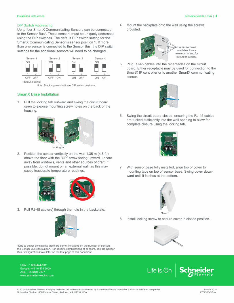
Six screw holes available. Use a
minimum of two for secure mounting.
DIP Switch Addressing Up to four SmartX Communicating Sensors can be connected to the Sensor Bus*. These sensors must be uniquely addressed using the DIP switches. The default DIP switch setting for the SmartX Communicating Sensor is sensor position 1. If more than one sensor is connected to the Sensor Bus, the DIP switch settings for the additional sensors will need to be changed.
Note: Black squares indicate DIP switch positions.
Sensor 1
OFF(default setting)
OFF1 2
ON
1 2ON OFF
ONSensor 3
1 2OFF ON
ONSensor 2
1 2ON
ON
ON
Sensor 4
4. Mount the backplate onto the wall using the screws provided.
5. Plug RJ-45 cables into the receptacles on the circuit board. Either receptacle may be used for connection to the SmartX IP controller or to another SmartX communicating sensor.
6. Swing the circuit board closed, ensuring the RJ-45 cables are tucked sufficiently into the wall opening to allow for complete closure using the locking tab.
7. With sensor base fully installed, align top of cover to mounting tabs on top of sensor base. Swing cover down-ward until it latches at the bottom.
8. Install locking screw to secure cover in closed position.
*Due to power constraints there are some limitations on the number of sensors the Sensor Bus can support. For specific combinations of sensors, see the Sensor Bus Configuration Calculator on the last page of this document.

schneider-electric.com | 5Installation Instructions
USA: +1 888-444-1311Europe: +46 10 478 2000Asia: +65 6484 7877www.schneider-electric.com
© 2018 Schneider Electric. All rights reserved. All trademarks are owned by Schneider Electric Industries SAS or its affiliated companies. March 2018 Schneider Electric · 800 Federal Street, Andover, MA 01810 USA Z207553-0C nk
Operation Button Functions
Display Icons
Mode Selection
Changing Temperature
Fahrenheit Selected
Temperature Adjust Mode
Cooling OnHeating On
Heating/Cooling Mode
Fan Adjust Mode
Occupancy Mode
Celsius Selected°F
°F°C
Change Values
Advance Menu
Change Values
After the “+” button is pressed, the icon blinks to show the user is actively editing.
Icon blinks during editing.
Icon blinks during editing.
Once in Editing mode, press the “+” or “-” buttons to reach the desired temperature.
Setpoint may differ from temperature reading.
Press “+” 3 more times.
Either wait 6 seconds or press the Menu Advance button to confirm changes.
Icon returns to solid grey. Numbers now denote temperature reading instead of setpoint.
Wait 6 seconds.°F
°C
P3 3
°F°C
Ws°F
°C°F°C
Press 3x Press
Sdtr
°F°C
A single press advances the
menu.
A solid icon indicates the active mode. In this case, Fan Speed.
The default mode is Temperature. This icon is ‘on’ solid (non-blinking).
Text changes to the active mode’s information.
Heating & Cooling
ModeOccupancy
Mode
Return to default(Temperature mode)
°F°C
°F°C
°F°C
°F°C °C
PressPressPressPress
Press
ºC/ºF
Note: During firmware updates, the display may appear to be off. Please allow five minutes for this process to complete before disconnecting the sensor. This may also occur when the sensor is first connected to a controller.

schneider-electric.com | 6Installation Instructions
USA: +1 888-444-1311Europe: +46 10 478 2000Asia: +65 6484 7877www.schneider-electric.com
© 2018 Schneider Electric. All rights reserved. All trademarks are owned by Schneider Electric Industries SAS or its affiliated companies. March 2018 Schneider Electric · 800 Federal Street, Andover, MA 01810 USA Z207553-0C nk
Operation, continued Changing Fan Speed
Changing Heating/Cooling Mode
Press the Advance Menu button twice.
Toggle between 1 of 3 options (where applicable).
The “-” button toggles through the choices backwards.
Return to the default screen.
Automatic
Heating
Wait 6 seconds.
2x Press
Cooling
°F°C
°F°C
°F°C
°F°C
°F°C
°F°C
°F°C
°F°C
Either wait 6 seconds or press the Menu Advance button to confirm changes.
Press the Menu Advance button.
Toggle between one of several options.(when applicable)
The “-” button toggles through the choices backwards
Return to the default screen. If returning to the Fan Speed menu item, a ‘2’ is displayed for fan speed.
Wait 6 seconds.
Low Speed
High Speed
Automatic
Off
°F°C
°F°C
°F°C
Either wait 6 seconds or press the Menu Advance button to confirm changes.
°F°C
°F°C
°F°C
°F°C
°F°C
°F°C
°F°C

schneider-electric.com | 7Installation Instructions
USA: +1 888-444-1311Europe: +46 10 478 2000Asia: +65 6484 7877www.schneider-electric.com
© 2018 Schneider Electric. All rights reserved. All trademarks are owned by Schneider Electric Industries SAS or its affiliated companies. March 2018 Schneider Electric · 800 Federal Street, Andover, MA 01810 USA Z207553-0C nk
Changing Celsius and Fahrenheit Scales
Operation, continued Changing Occupancy Mode
In this example, ºF is blinking. Toggle between one of two options (where applicable).
Always does the opposite of the ‘+’ button.
en
e
Display shows temperature with the units flashing to indicate the device is in Editing mode.
Press the Menu Advance button 4 times.
°F°C
°F°C
°F°C
°F°C
°F°C
Return to the default screen.
Wait 6 seconds
4x
Either wait 6 seconds or press the Menu Advance button to confirm changes.
Press the Advance Menu button 3 times.
Toggle between 1 of 2 options (where applicable).
The “-” button toggles through the choices backwards
Return to the default screen.
Occupied
Unoccupied
Wait 6 seconds.
3x
°F°C
°F°C
°F°C
°F°C
°F°C
°F°C
A
°F°C
A
Either wait 6 seconds or press the Menu Advance button to confirm changes.

schneider-electric.com | 8Installation Instructions
USA: +1 888-444-1311Europe: +46 10 478 2000Asia: +65 6484 7877www.schneider-electric.com
© 2018 Schneider Electric. All rights reserved. All trademarks are owned by Schneider Electric Industries SAS or its affiliated companies. March 2018 Schneider Electric · 800 Federal Street, Andover, MA 01810 USA Z207553-0C nk
Key Combinations
• Blank covers: – Up to four of any combination of sensor base types
• 3-button and touchscreen covers: – Up to two sensor bases with CO2
– Up to four non-CO2 sensor bases• LCD temperature combination sensors:
– Up to four are supported
Description Model Number Power/mWSensor Base, Temperature SXWSBTXXXSXX 90
Sensor Base, Temperature, Humidity SXWSBTHXXSXX 90
Sensor Base, Temperature, CO2 SXWSBTXCXSXX 490
Sensor Base, Temperature, Humidity, CO2 SXWSBTHCXSXX 490
Sensor, Temp, LCD, Setpoint, Pushbutton Operation with Cover Plate SXWSATXXXSLX 80
Sensor, Temp, 10K T3, Non-communicating, with Cover Plate SXWSATXXXRXX 0
Cover Plate, Blank Cover SXWSCBXSELXX 0
Cover Plate, User Interface, Basic SXWSCDXSELXX 190
Cover Plate, Override, Setpoint SXWSC3XSELXX 190
Cover Plate, User Interface, Basic, Occupancy SXWSCDPSELXX 210
Cover Plate, Override, Setpoint, Occupancy SXWSC3PSELXX 210
Cover Plate, Blank Cover, Occupancy SXWSCBPSELXX 20
eCommission Bluetooth Adapter SXWBTAECXX10001* 300
Sensor Bus Configuration Calculator Calculate Power/mW to Validate Sensor Bus Configuration
Add power/mW for all covers, combination units and bases to be used on a single sensor bus for total sensor bus wattage. The sensor bus will support current of up to 2000 mW. Device combinations totalling more than 2000 mW will not be sup-ported on the sensor bus.
Sensor Bus Power Table
*The eCommission Bluetooth Adapter is used temporarily for commissioning and servicing only.
schneider-electric.com | 9Installation Instructions
USA: +1 888-444-1311Europe: +46 10 478 2000Asia: +65 6484 7877www.schneider-electric.com
© 2018 Schneider Electric. All rights reserved. All trademarks are owned by Schneider Electric Industries SAS or its affiliated companies. March 2018 Schneider Electric · 800 Federal Street, Andover, MA 01810 USA Z207553-0C nk
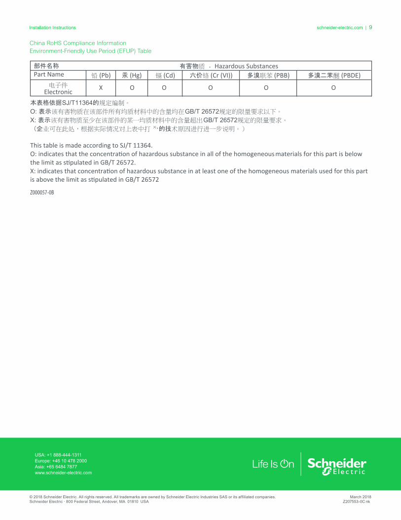
China RoHS Compliance Information Environment-Friendly Use Period (EFUP) Table
本表格依据SJ/T11364的规定编制。
O: 表示该有害物质在该部件所有均质材料中的含量均在GB/T 26572规定的限量要求以下。
X: 表示该有害物质至少在该部件的某一均质材料中的含量超出GB/T 26572规定的限量要求。
(企业可在此处,根据实际情况对上表中打 的技术原因进行进一步说明。)
This table is made according to SJ/T 11364.O: indicates that the concentration of hazardous substance in all of the homogeneous materials for this part is below the limit as stipulated in GB/T 26572.X: indicates that concentration of hazardous substance in at least one of the homogeneous materials used for this part
X O O O O O
is above the limit as stipulated in GB/T 26572
Z000057-0B
部件名称
Part Name有害物质 - Hazardous Substances
铅 (Pb) 汞 (Hg) 镉 (Cd) 六价铬 (Cr (VI)) 多溴联苯 (PBB) 多溴二苯醚 (PBDE)电子件
Electronic


![SmartX Framework 가이드 · 2020-07-09 · | 8 SmartX Framework 프로그래밍 가이드 [인자]• int iBitIndex : Port에서 출력 상태를 제어할 Pin 번호. 0번 Pin의](https://static.fdocuments.in/doc/165x107/5f4355c10105115996570d45/smartx-framework-eeoe-2020-07-09-8-smartx-framework-eoeeee-eeoe.jpg)