SmartWindow - Spirent · Contents SmartWindow User Guide | 7 Tests Using the XLW-3721A/XFP-3731A...
716
P/N 71-004148 REV A User Guide SmartWindow April 2008
Transcript of SmartWindow - Spirent · Contents SmartWindow User Guide | 7 Tests Using the XLW-3721A/XFP-3731A...
P/N 71-004148 REV A
User Guide
SmartWindowApril 2008

Spirent Communications, Inc.26750 Agoura RoadCalabasas, CA91302 USA
Copyright© 2008 Spirent Communications, Inc. All Rights Reserved.
All of the company names and/or brand names and/or product names referred to in this document, in particular, the name “Spirent” and its logo device, are either registered trademarks or trademarks of Spirent plc and its subsidiaries, pending registration in accordance with relevant national laws. All other registered trademarks or trademarks are the property of their respective owners. The information contained in this document is subject to change without notice and does not represent a commitment on the part of Spirent Communications. The information in this document is believed to be accurate and reliable, however, Spirent Communications assumes no responsibility or liability for any errors or inaccuracies that may appear in the document.
Limited WarrantySpirent Communications, Inc. (“Spirent”) warrants that its Products will conform to the description on the face of order, that it will convey good title thereto, and that the Product will be delivered free from any lawful security interest or other lien or encumbrance.
Spirent further warrants to Customer that hardware which it supplies and the tangible media on which it supplies software will be free from significant defects in materials and workmanship for a period of twelve (12) months, except as otherwise noted, from the date of delivery (the “Hardware Warranty Period”), under normal use and conditions.
To the extent the Product is or contains software (“Software”), Spirent also warrants that, if properly used by Customer in accordance with the Software License Agreement, the Software which it supplies will operate in material conformity with the specifications supplied by Spirent for such Software for a period of ninety (90) days from the date of delivery (the “Software Warranty Period”). The “Product Warranty Period” shall mean the Hardware Warranty Period or the Software Warranty Period, as applicable. Spirent does not warrant that the functions contained in the Software will meet a specific requirement or that the operation will be uninterrupted or error free. Spirent shall have no warranty obligations whatsoever with respect to any Software which has been modified in any manner by Customer or any third party.
Defective Products and Software under warranty shall be, at Spirent's discretion, repaired or replaced or a credit issued to Customer's account for an amount equal to the price paid for such Product provided that: (a) such Product is returned to Spirent after first obtaining a return authorization number and shipping instructions, freight prepaid, to Spirent's location in the United States; (b) Customer provides a written explanation of the defect or Software failure claimed by Customer; and (c) the claimed defect actually exists and was not caused by neglect, accident, misuse, improper installation, improper repair, fire, flood, lightning, power surges, earthquake, or alteration. Spirent will ship repaired Products to Customer, freight prepaid, based on reasonable best efforts after the receipt of defective Products. Except as otherwise stated, any claim on account of defective materials or for any other cause whatsoever will conclusively be deemed waived by Customer unless written notice thereof is given to Spirent within the Warranty Period. Spirent reserves the right to change the warranty and service policy set forth above at any time, after reasonable notice and without liability to Customer.
TO THE EXTENT PERMITTED BY APPLICABLE LAW, ALL IMPLIED WARRANTIES, INCLUDING BUT NOT LIMITED TO IMPLIED WARRANTIES OF MERCHANTABILITY, NONINFRINGEMENT AND FITNESS FOR A PARTICULAR PURPOSE, ARE HEREBY EXCLUDED, AND THE LIABILITY OF SPIRENT, IF ANY, FOR DAMAGE RELATING TO ANY ALLEGEDLY DEFECTIVE PRODUCT SHALL BE LIMITED TO THE ACTUAL PRICE PAID BY THE CUSTOMER FOR SUCH PRODUCT. THE PROVISIONS SET FORTH ABOVE STATE SPIRENT'S ENTIRE RESPONSIBILITY AND CUSTOMER'S SOLE AND EXCLUSIVE REMEDY WITH RESPECT TO ANY BREACH OF ANY WARRANTY.
Contents
About this Guide . . . . . . . . . . . . . . . . . . . . . . . . . . . . . . . . . . . . . . . . . . . . . . . . . . . . . . . . 13Introduction . . . . . . . . . . . . . . . . . . . . . . . . . . . . . . . . . . . . . . . . . . . . . . . . . . . . . . . . . . . . . . . 14About SmartWindow Documentation . . . . . . . . . . . . . . . . . . . . . . . . . . . . . . . . . . . . . . . . . . . 14
Using SmartWindow Online Help . . . . . . . . . . . . . . . . . . . . . . . . . . . . . . . . . . . . . . . . . . 14SmartBits Hardware Handling/Cleaning Practices . . . . . . . . . . . . . . . . . . . . . . . . . . . . . . . . . 15How to Contact Us. . . . . . . . . . . . . . . . . . . . . . . . . . . . . . . . . . . . . . . . . . . . . . . . . . . . . . . . . . 16
Chapter 1: SmartWindow Overview . . . . . . . . . . . . . . . . . . . . . . . . . . . . . . . . . . . . . 17Version Information and Compatibility. . . . . . . . . . . . . . . . . . . . . . . . . . . . . . . . . . . . . . . . . . 18What Are SmartCards and Modules?. . . . . . . . . . . . . . . . . . . . . . . . . . . . . . . . . . . . . . . . . . . . 20
SmartCards and Modules Supported . . . . . . . . . . . . . . . . . . . . . . . . . . . . . . . . . . . . . . . . 20Disk Space Requirements for Large Tests . . . . . . . . . . . . . . . . . . . . . . . . . . . . . . . . . . . . . . . . 20Tests Described in this Guide . . . . . . . . . . . . . . . . . . . . . . . . . . . . . . . . . . . . . . . . . . . . . . . . . 21Basic Terminology in SmartBits Testing. . . . . . . . . . . . . . . . . . . . . . . . . . . . . . . . . . . . . . . . . 24
Chapter 2: Install and Connect . . . . . . . . . . . . . . . . . . . . . . . . . . . . . . . . . . . . . . . . . . 27Installing SmartWindow . . . . . . . . . . . . . . . . . . . . . . . . . . . . . . . . . . . . . . . . . . . . . . . . . . . . . 28
PC Workstation Requirements . . . . . . . . . . . . . . . . . . . . . . . . . . . . . . . . . . . . . . . . . . . . . 28Software Installation . . . . . . . . . . . . . . . . . . . . . . . . . . . . . . . . . . . . . . . . . . . . . . . . . . . . . 29Testing with Multiple SmartBits Chassis . . . . . . . . . . . . . . . . . . . . . . . . . . . . . . . . . . . . . 30
Starting SmartWindow. . . . . . . . . . . . . . . . . . . . . . . . . . . . . . . . . . . . . . . . . . . . . . . . . . . . . . . 31SmartWindow Launcher . . . . . . . . . . . . . . . . . . . . . . . . . . . . . . . . . . . . . . . . . . . . . . . . . . 31
Setting up a Connection . . . . . . . . . . . . . . . . . . . . . . . . . . . . . . . . . . . . . . . . . . . . . . . . . . . . . . 42Initial SmartBits Configuration . . . . . . . . . . . . . . . . . . . . . . . . . . . . . . . . . . . . . . . . . . . . 42Configuring SmartWindow for an Ethernet Connection . . . . . . . . . . . . . . . . . . . . . . . . . 45Reconfiguring SmartBits IP Address . . . . . . . . . . . . . . . . . . . . . . . . . . . . . . . . . . . . . . . . 46Disk Space Requirements for Large Tests . . . . . . . . . . . . . . . . . . . . . . . . . . . . . . . . . . . . 47
Chapter 3: SmartWindow Menus. . . . . . . . . . . . . . . . . . . . . . . . . . . . . . . . . . . . . . . . 49SmartWindow User Interface. . . . . . . . . . . . . . . . . . . . . . . . . . . . . . . . . . . . . . . . . . . . . . . . . . 50
Connected to SmartBits 2000 . . . . . . . . . . . . . . . . . . . . . . . . . . . . . . . . . . . . . . . . . . . . . . 50Connected to SmartBits 200 . . . . . . . . . . . . . . . . . . . . . . . . . . . . . . . . . . . . . . . . . . . . . . . 51Connected to SmartBits 600x/6000x . . . . . . . . . . . . . . . . . . . . . . . . . . . . . . . . . . . . . . . . 53
File Menu . . . . . . . . . . . . . . . . . . . . . . . . . . . . . . . . . . . . . . . . . . . . . . . . . . . . . . . . . . . . . . . . . 55Edit Menu. . . . . . . . . . . . . . . . . . . . . . . . . . . . . . . . . . . . . . . . . . . . . . . . . . . . . . . . . . . . . . . . . 56
Copy/Paste Port to Port. . . . . . . . . . . . . . . . . . . . . . . . . . . . . . . . . . . . . . . . . . . . . . . . . . . 56Copy/Paste Chassis to Chassis . . . . . . . . . . . . . . . . . . . . . . . . . . . . . . . . . . . . . . . . . . . . . 57Copy/Paste Port to Chassis . . . . . . . . . . . . . . . . . . . . . . . . . . . . . . . . . . . . . . . . . . . . . . . . 58
Actions Menu. . . . . . . . . . . . . . . . . . . . . . . . . . . . . . . . . . . . . . . . . . . . . . . . . . . . . . . . . . . . . . 59Options Menu. . . . . . . . . . . . . . . . . . . . . . . . . . . . . . . . . . . . . . . . . . . . . . . . . . . . . . . . . . . . . . 62
ATM Traffic Setup . . . . . . . . . . . . . . . . . . . . . . . . . . . . . . . . . . . . . . . . . . . . . . . . . . . . . . 62Connection Setup . . . . . . . . . . . . . . . . . . . . . . . . . . . . . . . . . . . . . . . . . . . . . . . . . . . . . . . 62
SmartWindow User Guide | 3
Contents
Preferences . . . . . . . . . . . . . . . . . . . . . . . . . . . . . . . . . . . . . . . . . . . . . . . . . . . . . . . . . . . . 62SmartBits 200/2000 . . . . . . . . . . . . . . . . . . . . . . . . . . . . . . . . . . . . . . . . . . . . . . . . . . . . . 63SmartBits 600x/6000x . . . . . . . . . . . . . . . . . . . . . . . . . . . . . . . . . . . . . . . . . . . . . . . . . . . 65
Tests Menu. . . . . . . . . . . . . . . . . . . . . . . . . . . . . . . . . . . . . . . . . . . . . . . . . . . . . . . . . . . . . . . . 70Backoff Truncation Exponent. . . . . . . . . . . . . . . . . . . . . . . . . . . . . . . . . . . . . . . . . . . . . . 70SmartMetrics Tests . . . . . . . . . . . . . . . . . . . . . . . . . . . . . . . . . . . . . . . . . . . . . . . . . . . . . . 70
Admin Menu . . . . . . . . . . . . . . . . . . . . . . . . . . . . . . . . . . . . . . . . . . . . . . . . . . . . . . . . . . . . . . 71SmartBits IP Configuration . . . . . . . . . . . . . . . . . . . . . . . . . . . . . . . . . . . . . . . . . . . . . . . 71SmartBits Users . . . . . . . . . . . . . . . . . . . . . . . . . . . . . . . . . . . . . . . . . . . . . . . . . . . . . . . . 72
View Menu. . . . . . . . . . . . . . . . . . . . . . . . . . . . . . . . . . . . . . . . . . . . . . . . . . . . . . . . . . . . . . . . 74Help Menu . . . . . . . . . . . . . . . . . . . . . . . . . . . . . . . . . . . . . . . . . . . . . . . . . . . . . . . . . . . . . . . . 75
Chapter 4: Basic Operational Theory. . . . . . . . . . . . . . . . . . . . . . . . . . . . . . . . . . . . 77SmartWindow Basics . . . . . . . . . . . . . . . . . . . . . . . . . . . . . . . . . . . . . . . . . . . . . . . . . . . . . . . . 78
Single Instances of SmartWindow . . . . . . . . . . . . . . . . . . . . . . . . . . . . . . . . . . . . . . . . . . 78Multiple Instances of SmartWindow . . . . . . . . . . . . . . . . . . . . . . . . . . . . . . . . . . . . . . . . . . . . 81
Multiple Instance Behavior. . . . . . . . . . . . . . . . . . . . . . . . . . . . . . . . . . . . . . . . . . . . . . . . 81Naming Connections . . . . . . . . . . . . . . . . . . . . . . . . . . . . . . . . . . . . . . . . . . . . . . . . . . . . . . . . 82
Host Name-to-Address Mapping . . . . . . . . . . . . . . . . . . . . . . . . . . . . . . . . . . . . . . . . . . . 83Grouping SmartCards . . . . . . . . . . . . . . . . . . . . . . . . . . . . . . . . . . . . . . . . . . . . . . . . . . . . . . . 84
Group Rules . . . . . . . . . . . . . . . . . . . . . . . . . . . . . . . . . . . . . . . . . . . . . . . . . . . . . . . . . . . 84Group Transmit and Trigger Setup (SmartBits 2000 only) . . . . . . . . . . . . . . . . . . . . . . . 84Defining a Group of SmartCards . . . . . . . . . . . . . . . . . . . . . . . . . . . . . . . . . . . . . . . . . . . 85Controlling a Group of SmartCards . . . . . . . . . . . . . . . . . . . . . . . . . . . . . . . . . . . . . . . . . 87Transmit Setup for a Group of SmartCards . . . . . . . . . . . . . . . . . . . . . . . . . . . . . . . . . . . 89Trigger Setup for a Group of SmartCards . . . . . . . . . . . . . . . . . . . . . . . . . . . . . . . . . . . . 89Displaying Counters for a Group of Ports . . . . . . . . . . . . . . . . . . . . . . . . . . . . . . . . . . . . 90
Multi-user Operation . . . . . . . . . . . . . . . . . . . . . . . . . . . . . . . . . . . . . . . . . . . . . . . . . . . . . . . . 92SmartBits 6000x Multi-user Operation. . . . . . . . . . . . . . . . . . . . . . . . . . . . . . . . . . . . . . . 92SmartBits 2000 Multi-user Operation. . . . . . . . . . . . . . . . . . . . . . . . . . . . . . . . . . . . . . . . 95Reserving SmartCards . . . . . . . . . . . . . . . . . . . . . . . . . . . . . . . . . . . . . . . . . . . . . . . . . . . 96
Configuration Files . . . . . . . . . . . . . . . . . . . . . . . . . . . . . . . . . . . . . . . . . . . . . . . . . . . . . . . . . 97Configuration File Types . . . . . . . . . . . . . . . . . . . . . . . . . . . . . . . . . . . . . . . . . . . . . . . . . 97Creating New Configuration Files . . . . . . . . . . . . . . . . . . . . . . . . . . . . . . . . . . . . . . . . . . 98Saving Individual SmartCard Configurations. . . . . . . . . . . . . . . . . . . . . . . . . . . . . . . . . 101Converting SmartWindow Configurations . . . . . . . . . . . . . . . . . . . . . . . . . . . . . . . . . . . 102
Configuring SmartBits Cards. . . . . . . . . . . . . . . . . . . . . . . . . . . . . . . . . . . . . . . . . . . . . . . . . 107Configuration Options . . . . . . . . . . . . . . . . . . . . . . . . . . . . . . . . . . . . . . . . . . . . . . . . . . 107Configuring Frame Content . . . . . . . . . . . . . . . . . . . . . . . . . . . . . . . . . . . . . . . . . . . . . . 108Configuring Network Interactions . . . . . . . . . . . . . . . . . . . . . . . . . . . . . . . . . . . . . . . . . 108
Types of Tests . . . . . . . . . . . . . . . . . . . . . . . . . . . . . . . . . . . . . . . . . . . . . . . . . . . . . . . . . . . . 109
Chapter 5: Advanced Operational Theory . . . . . . . . . . . . . . . . . . . . . . . . . . . . . . 111Setting up IP Multicast Groups . . . . . . . . . . . . . . . . . . . . . . . . . . . . . . . . . . . . . . . . . . . . . . . 112
About IGMP . . . . . . . . . . . . . . . . . . . . . . . . . . . . . . . . . . . . . . . . . . . . . . . . . . . . . . . . . . 114IGMP in SmartWindow . . . . . . . . . . . . . . . . . . . . . . . . . . . . . . . . . . . . . . . . . . . . . . . . . 114IGMP with VLAN . . . . . . . . . . . . . . . . . . . . . . . . . . . . . . . . . . . . . . . . . . . . . . . . . . . . . 115How IP and MAC Addresses Identify Multicast Traffic . . . . . . . . . . . . . . . . . . . . . . . . 115Set up Multicast Streams on SmartBits 200/2000 SmartCards . . . . . . . . . . . . . . . . . . . 116Set up IGMP for SmartBits 600x/6000x Modules . . . . . . . . . . . . . . . . . . . . . . . . . . . . . 120Multicast Groups and VLANs . . . . . . . . . . . . . . . . . . . . . . . . . . . . . . . . . . . . . . . . . . . . 129VLAN Priority . . . . . . . . . . . . . . . . . . . . . . . . . . . . . . . . . . . . . . . . . . . . . . . . . . . . . . . . 130
4 | SmartWindow User Guide
Contents
SmartCounters . . . . . . . . . . . . . . . . . . . . . . . . . . . . . . . . . . . . . . . . . . . . . . . . . . . . . . . . . . . . 131SmartCounters for SmartBits 200/2000 Cards . . . . . . . . . . . . . . . . . . . . . . . . . . . . . . . . 131
Smartbit.ini Files . . . . . . . . . . . . . . . . . . . . . . . . . . . . . . . . . . . . . . . . . . . . . . . . . . . . . . . . . . 142Using Triggers and Capture . . . . . . . . . . . . . . . . . . . . . . . . . . . . . . . . . . . . . . . . . . . . . . . . . . 145
Capturing Packets . . . . . . . . . . . . . . . . . . . . . . . . . . . . . . . . . . . . . . . . . . . . . . . . . . . . . . 148Sample Procedure Using Capture . . . . . . . . . . . . . . . . . . . . . . . . . . . . . . . . . . . . . . . . . . 155
Sending Ping, SNMP, and RIP Frames . . . . . . . . . . . . . . . . . . . . . . . . . . . . . . . . . . . . . . . . . 156Editing Frames . . . . . . . . . . . . . . . . . . . . . . . . . . . . . . . . . . . . . . . . . . . . . . . . . . . . . . . . . . . . 157
Creating Custom Frames . . . . . . . . . . . . . . . . . . . . . . . . . . . . . . . . . . . . . . . . . . . . . . . . 157Editing Protocol Bytes in Test Frames . . . . . . . . . . . . . . . . . . . . . . . . . . . . . . . . . . . . . . 159
MII Registers . . . . . . . . . . . . . . . . . . . . . . . . . . . . . . . . . . . . . . . . . . . . . . . . . . . . . . . . . . . . . 163Shortcuts . . . . . . . . . . . . . . . . . . . . . . . . . . . . . . . . . . . . . . . . . . . . . . . . . . . . . . . . . . . . . 163Enabling Autonegotiation . . . . . . . . . . . . . . . . . . . . . . . . . . . . . . . . . . . . . . . . . . . . . . . . 165
Using the Data Decoder . . . . . . . . . . . . . . . . . . . . . . . . . . . . . . . . . . . . . . . . . . . . . . . . . . . . . 167Using the Observer . . . . . . . . . . . . . . . . . . . . . . . . . . . . . . . . . . . . . . . . . . . . . . . . . . . . . 167
Testing with IPv6 Streams . . . . . . . . . . . . . . . . . . . . . . . . . . . . . . . . . . . . . . . . . . . . . . . . . . . 169SmartBits Module Support for IPv6 Streams . . . . . . . . . . . . . . . . . . . . . . . . . . . . . . . . . 169Frame Header Length . . . . . . . . . . . . . . . . . . . . . . . . . . . . . . . . . . . . . . . . . . . . . . . . . . . 169Selecting an Address Display Format. . . . . . . . . . . . . . . . . . . . . . . . . . . . . . . . . . . . . . . 171IPv6 Header Fields . . . . . . . . . . . . . . . . . . . . . . . . . . . . . . . . . . . . . . . . . . . . . . . . . . . . . 173Calculating Protocol and Frame Size for IPv6 Streams . . . . . . . . . . . . . . . . . . . . . . . . . 175Neighbor Discovery Protocol . . . . . . . . . . . . . . . . . . . . . . . . . . . . . . . . . . . . . . . . . . . . . 179
Jumbo Frames . . . . . . . . . . . . . . . . . . . . . . . . . . . . . . . . . . . . . . . . . . . . . . . . . . . . . . . . . . . . 184Module Support . . . . . . . . . . . . . . . . . . . . . . . . . . . . . . . . . . . . . . . . . . . . . . . . . . . . . . . 184Enabling Jumbo Frames . . . . . . . . . . . . . . . . . . . . . . . . . . . . . . . . . . . . . . . . . . . . . . . . . 184Exceptions. . . . . . . . . . . . . . . . . . . . . . . . . . . . . . . . . . . . . . . . . . . . . . . . . . . . . . . . . . . . 185Using Jabber Count to Simulate Jumbo Frames. . . . . . . . . . . . . . . . . . . . . . . . . . . . . . . 185
Virtual Flow Cyclic ARPs and ARP Requests . . . . . . . . . . . . . . . . . . . . . . . . . . . . . . . . . . . 186Module Support . . . . . . . . . . . . . . . . . . . . . . . . . . . . . . . . . . . . . . . . . . . . . . . . . . . . . . . 186Summary. . . . . . . . . . . . . . . . . . . . . . . . . . . . . . . . . . . . . . . . . . . . . . . . . . . . . . . . . . . . . 187Defining Receive Properties of ARP Requests. . . . . . . . . . . . . . . . . . . . . . . . . . . . . . . . 188Defining Properties of Virtual Flow Cyclic ARPs . . . . . . . . . . . . . . . . . . . . . . . . . . . . . 189
Gratuitous ARP Mode . . . . . . . . . . . . . . . . . . . . . . . . . . . . . . . . . . . . . . . . . . . . . . . . . . . . . . 196Gratuitous ARP Counter Behavior on TeraMetrics Cards . . . . . . . . . . . . . . . . . . . . . . . 197
Chapter 6: Traditional LAN Testing . . . . . . . . . . . . . . . . . . . . . . . . . . . . . . . . . . . . . 199Traditional Testing vs. SmartMetrics. . . . . . . . . . . . . . . . . . . . . . . . . . . . . . . . . . . . . . . . . . . 200
Traditional Mode (for Simulating Layer 2 and Layer 3) . . . . . . . . . . . . . . . . . . . . . . . . 200SmartMetrics. . . . . . . . . . . . . . . . . . . . . . . . . . . . . . . . . . . . . . . . . . . . . . . . . . . . . . . . . . 201
Testing Cable Modems . . . . . . . . . . . . . . . . . . . . . . . . . . . . . . . . . . . . . . . . . . . . . . . . . . . . . 203General Guidelines . . . . . . . . . . . . . . . . . . . . . . . . . . . . . . . . . . . . . . . . . . . . . . . . . . . . . 203Packet Loss Test . . . . . . . . . . . . . . . . . . . . . . . . . . . . . . . . . . . . . . . . . . . . . . . . . . . . . . . 204Connecting the Cables . . . . . . . . . . . . . . . . . . . . . . . . . . . . . . . . . . . . . . . . . . . . . . . . . . 204Preparing the SUT . . . . . . . . . . . . . . . . . . . . . . . . . . . . . . . . . . . . . . . . . . . . . . . . . . . . . 204Testing Packet Loss in Traditional Mode . . . . . . . . . . . . . . . . . . . . . . . . . . . . . . . . . . . . 205USB Query . . . . . . . . . . . . . . . . . . . . . . . . . . . . . . . . . . . . . . . . . . . . . . . . . . . . . . . . . . . 213SmartMetrics Testing . . . . . . . . . . . . . . . . . . . . . . . . . . . . . . . . . . . . . . . . . . . . . . . . . . . 213
Testing VLAN Tagging Across a Gigabit Uplink . . . . . . . . . . . . . . . . . . . . . . . . . . . . . . . . . 214Preparing the Device Under Test (DUT) . . . . . . . . . . . . . . . . . . . . . . . . . . . . . . . . . . . . 216Setting up the Test . . . . . . . . . . . . . . . . . . . . . . . . . . . . . . . . . . . . . . . . . . . . . . . . . . . . . 217
Between Layer 2 and Layer 3 . . . . . . . . . . . . . . . . . . . . . . . . . . . . . . . . . . . . . . . . . . . . . . . . 227Testing QOS for Gigabit Routers. . . . . . . . . . . . . . . . . . . . . . . . . . . . . . . . . . . . . . . . . . . . . . 228
SmartWindow User Guide | 5
Contents
Chapter 7: SmartMetrics Testing. . . . . . . . . . . . . . . . . . . . . . . . . . . . . . . . . . . . . . . 235Layer 3 Switching . . . . . . . . . . . . . . . . . . . . . . . . . . . . . . . . . . . . . . . . . . . . . . . . . . . . . . . . . 236
Test Methodology . . . . . . . . . . . . . . . . . . . . . . . . . . . . . . . . . . . . . . . . . . . . . . . . . . . . . . 236About Streams. . . . . . . . . . . . . . . . . . . . . . . . . . . . . . . . . . . . . . . . . . . . . . . . . . . . . . . . . 236
Required Steps for SmartMetrics (Layer 3) Testing . . . . . . . . . . . . . . . . . . . . . . . . . . . . . . . 238Port Setup . . . . . . . . . . . . . . . . . . . . . . . . . . . . . . . . . . . . . . . . . . . . . . . . . . . . . . . . . . . . 238Address Resolution Protocol (ARP) . . . . . . . . . . . . . . . . . . . . . . . . . . . . . . . . . . . . . . . . 243Preparing the Device Under Test (DUT) . . . . . . . . . . . . . . . . . . . . . . . . . . . . . . . . . . . . 244Preferences to Review . . . . . . . . . . . . . . . . . . . . . . . . . . . . . . . . . . . . . . . . . . . . . . . . . . 244
Test Using the LAN-3321A TeraMetrics Module . . . . . . . . . . . . . . . . . . . . . . . . . . . . . . . . . 246Design of Test . . . . . . . . . . . . . . . . . . . . . . . . . . . . . . . . . . . . . . . . . . . . . . . . . . . . . . . . . 247Global Default Settings. . . . . . . . . . . . . . . . . . . . . . . . . . . . . . . . . . . . . . . . . . . . . . . . . . 247Set up Port Addresses . . . . . . . . . . . . . . . . . . . . . . . . . . . . . . . . . . . . . . . . . . . . . . . . . . . 248Streams Setup Window. . . . . . . . . . . . . . . . . . . . . . . . . . . . . . . . . . . . . . . . . . . . . . . . . . 251Adding a Stream . . . . . . . . . . . . . . . . . . . . . . . . . . . . . . . . . . . . . . . . . . . . . . . . . . . . . . . 258Configuring a Stream . . . . . . . . . . . . . . . . . . . . . . . . . . . . . . . . . . . . . . . . . . . . . . . . . . . 260Send Traffic and View Counters . . . . . . . . . . . . . . . . . . . . . . . . . . . . . . . . . . . . . . . . . . 265
Testing Using ML-7710 SmartMetrics SmartCards . . . . . . . . . . . . . . . . . . . . . . . . . . . . . . . 265Review Global Default Settings . . . . . . . . . . . . . . . . . . . . . . . . . . . . . . . . . . . . . . . . . . . 266Set up One Layer 3 Stream per ML-7710 SmartCard . . . . . . . . . . . . . . . . . . . . . . . . . . 267Send Traffic and View Counters . . . . . . . . . . . . . . . . . . . . . . . . . . . . . . . . . . . . . . . . . . 272
Setting Multiple Streams per Card. . . . . . . . . . . . . . . . . . . . . . . . . . . . . . . . . . . . . . . . . . . . . 273Using Group Start . . . . . . . . . . . . . . . . . . . . . . . . . . . . . . . . . . . . . . . . . . . . . . . . . . . . . . 277
About SmartMetrics . . . . . . . . . . . . . . . . . . . . . . . . . . . . . . . . . . . . . . . . . . . . . . . . . . . . . . . . 278SmartMetrics Test Requirements . . . . . . . . . . . . . . . . . . . . . . . . . . . . . . . . . . . . . . . . . . 279
How to Run SmartMetrics Tests . . . . . . . . . . . . . . . . . . . . . . . . . . . . . . . . . . . . . . . . . . . . . . 284Simultaneous Starting in SmartMetrics Tests. . . . . . . . . . . . . . . . . . . . . . . . . . . . . . . . . 286Selecting and Deselecting Ports for SmartMetrics Tests . . . . . . . . . . . . . . . . . . . . . . . . 286SmartMetrics Test Results Window Menus . . . . . . . . . . . . . . . . . . . . . . . . . . . . . . . . . . 287SmartMetrics Test Results Window Toolbar . . . . . . . . . . . . . . . . . . . . . . . . . . . . . . . . . 288
How to Optimize 16-bit Latency Testing . . . . . . . . . . . . . . . . . . . . . . . . . . . . . . . . . . . . . . . 289SmartMetrics 16-bit Tests . . . . . . . . . . . . . . . . . . . . . . . . . . . . . . . . . . . . . . . . . . . . . . . . . . . 290
(16) Latency Distribution Test . . . . . . . . . . . . . . . . . . . . . . . . . . . . . . . . . . . . . . . . . . . . 291(16) Latency per VTE Test . . . . . . . . . . . . . . . . . . . . . . . . . . . . . . . . . . . . . . . . . . . . . . . 295(16) Latency Over Time Test . . . . . . . . . . . . . . . . . . . . . . . . . . . . . . . . . . . . . . . . . . . . . 296
Other SmartMetrics Tests . . . . . . . . . . . . . . . . . . . . . . . . . . . . . . . . . . . . . . . . . . . . . . . . . . . 297Sequence Tracking Test . . . . . . . . . . . . . . . . . . . . . . . . . . . . . . . . . . . . . . . . . . . . . . . . . 297Sequence + Latency Test . . . . . . . . . . . . . . . . . . . . . . . . . . . . . . . . . . . . . . . . . . . . . . . . 297Real Time Latency Test . . . . . . . . . . . . . . . . . . . . . . . . . . . . . . . . . . . . . . . . . . . . . . . . . 298Raw Packet Tags Test. . . . . . . . . . . . . . . . . . . . . . . . . . . . . . . . . . . . . . . . . . . . . . . . . . . 303ARP Exchange Times Test . . . . . . . . . . . . . . . . . . . . . . . . . . . . . . . . . . . . . . . . . . . . . . . 304Frame Variation Test . . . . . . . . . . . . . . . . . . . . . . . . . . . . . . . . . . . . . . . . . . . . . . . . . . . 304
SmartMetrics Test Results . . . . . . . . . . . . . . . . . . . . . . . . . . . . . . . . . . . . . . . . . . . . . . . . . . . 306Latency in SmartMetrics Test Results . . . . . . . . . . . . . . . . . . . . . . . . . . . . . . . . . . . . . . 306Interpreting SmartMetrics Test Results . . . . . . . . . . . . . . . . . . . . . . . . . . . . . . . . . . . . . 307Viewing SmartMetrics Test Results (Histograms) . . . . . . . . . . . . . . . . . . . . . . . . . . . . . 307
Detailed Tracking and Statistical Results . . . . . . . . . . . . . . . . . . . . . . . . . . . . . . . . . . . . . . . 308Latency Tests . . . . . . . . . . . . . . . . . . . . . . . . . . . . . . . . . . . . . . . . . . . . . . . . . . . . . . . . . 310Viewing ARP Response Times. . . . . . . . . . . . . . . . . . . . . . . . . . . . . . . . . . . . . . . . . . . . 314
Chapter 8: Testing Gigabit Routers. . . . . . . . . . . . . . . . . . . . . . . . . . . . . . . . . . . . . 315Testing Gigabit Routers with SmartMetrics . . . . . . . . . . . . . . . . . . . . . . . . . . . . . . . . . . . . . 316
6 | SmartWindow User Guide

Contents
Tests Using the XLW-3721A/XFP-3731A TeraMetrics Modules . . . . . . . . . . . . . . . . . . . . 318About the XLW-3721A and XFP-3731A TeraMetrics Modules . . . . . . . . . . . . . . . . . . 318Information on Transceivers and XENPAK/XFP Profiles . . . . . . . . . . . . . . . . . . . . . . . 320Port Menu . . . . . . . . . . . . . . . . . . . . . . . . . . . . . . . . . . . . . . . . . . . . . . . . . . . . . . . . . . . . 320Accessing Port Setup . . . . . . . . . . . . . . . . . . . . . . . . . . . . . . . . . . . . . . . . . . . . . . . . . . . 326General Tab. . . . . . . . . . . . . . . . . . . . . . . . . . . . . . . . . . . . . . . . . . . . . . . . . . . . . . . . . . . 328SONET/SDH Tab . . . . . . . . . . . . . . . . . . . . . . . . . . . . . . . . . . . . . . . . . . . . . . . . . . . . . . 332IPv4 Stack and IPv6 Stack Tabs . . . . . . . . . . . . . . . . . . . . . . . . . . . . . . . . . . . . . . . . . . . 334DiffServ Tab . . . . . . . . . . . . . . . . . . . . . . . . . . . . . . . . . . . . . . . . . . . . . . . . . . . . . . . . . . 335Link Alarms Tab. . . . . . . . . . . . . . . . . . . . . . . . . . . . . . . . . . . . . . . . . . . . . . . . . . . . . . . 336Link Fault Signaling Tab . . . . . . . . . . . . . . . . . . . . . . . . . . . . . . . . . . . . . . . . . . . . . . . . 337Layer 3 Setup: IPv4 Stack and IPv6 Stack . . . . . . . . . . . . . . . . . . . . . . . . . . . . . . . . . . . 339Configure Streams on the Transmitting Card . . . . . . . . . . . . . . . . . . . . . . . . . . . . . . . . . 340Set up the DUT . . . . . . . . . . . . . . . . . . . . . . . . . . . . . . . . . . . . . . . . . . . . . . . . . . . . . . . . 341Send Traffic and View Counters . . . . . . . . . . . . . . . . . . . . . . . . . . . . . . . . . . . . . . . . . . 341
XAUI Testing. . . . . . . . . . . . . . . . . . . . . . . . . . . . . . . . . . . . . . . . . . . . . . . . . . . . . . . . . . . . . 342Overview of XAUI and MDIO. . . . . . . . . . . . . . . . . . . . . . . . . . . . . . . . . . . . . . . . . . . . 342SmartBits XAUI Extender Unit . . . . . . . . . . . . . . . . . . . . . . . . . . . . . . . . . . . . . . . . . . . 345Typical XAUI Test Bench . . . . . . . . . . . . . . . . . . . . . . . . . . . . . . . . . . . . . . . . . . . . . . . 346Setting up and Running XAUI Tests . . . . . . . . . . . . . . . . . . . . . . . . . . . . . . . . . . . . . . . 347
Test Using the LAN-3710AL/AE/AS 10GbE Module . . . . . . . . . . . . . . . . . . . . . . . . . . . . . 355About the LAN-3710AL/AE/AS 10GbE Module . . . . . . . . . . . . . . . . . . . . . . . . . . . . . 355Reserve the Ports . . . . . . . . . . . . . . . . . . . . . . . . . . . . . . . . . . . . . . . . . . . . . . . . . . . . . . 356Review the Port Setup. . . . . . . . . . . . . . . . . . . . . . . . . . . . . . . . . . . . . . . . . . . . . . . . . . . 356Configure Streams on the Transmitting Port . . . . . . . . . . . . . . . . . . . . . . . . . . . . . . . . . 358Editing Streams in the Tx Control Panel . . . . . . . . . . . . . . . . . . . . . . . . . . . . . . . . . . . . 365Setting up Triggers . . . . . . . . . . . . . . . . . . . . . . . . . . . . . . . . . . . . . . . . . . . . . . . . . . . . . 371Set up the DUT . . . . . . . . . . . . . . . . . . . . . . . . . . . . . . . . . . . . . . . . . . . . . . . . . . . . . . . . 373Send Traffic and View Counters . . . . . . . . . . . . . . . . . . . . . . . . . . . . . . . . . . . . . . . . . . 373
Test Using the LAN-3311A TeraMetrics Module . . . . . . . . . . . . . . . . . . . . . . . . . . . . . . . . . 374About the LAN-3311A TeraMetrics Module . . . . . . . . . . . . . . . . . . . . . . . . . . . . . . . . . 374Test Methodology . . . . . . . . . . . . . . . . . . . . . . . . . . . . . . . . . . . . . . . . . . . . . . . . . . . . . . 375Gigabit Setup . . . . . . . . . . . . . . . . . . . . . . . . . . . . . . . . . . . . . . . . . . . . . . . . . . . . . . . . . 375Layer 3 Setup . . . . . . . . . . . . . . . . . . . . . . . . . . . . . . . . . . . . . . . . . . . . . . . . . . . . . . . . . 377Configure Streams on the Transmitting Card . . . . . . . . . . . . . . . . . . . . . . . . . . . . . . . . . 378Set up the DUT . . . . . . . . . . . . . . . . . . . . . . . . . . . . . . . . . . . . . . . . . . . . . . . . . . . . . . . . 379Send Traffic and View Counters . . . . . . . . . . . . . . . . . . . . . . . . . . . . . . . . . . . . . . . . . . 379
Test Using the LAN-3201B/C SmartMetrics Module . . . . . . . . . . . . . . . . . . . . . . . . . . . . . . 380About the LAN-3201B/C SmartMetrics Module . . . . . . . . . . . . . . . . . . . . . . . . . . . . . . 380Test Methodology . . . . . . . . . . . . . . . . . . . . . . . . . . . . . . . . . . . . . . . . . . . . . . . . . . . . . . 381Gigabit Setup . . . . . . . . . . . . . . . . . . . . . . . . . . . . . . . . . . . . . . . . . . . . . . . . . . . . . . . . . 382Layer 3 Setup . . . . . . . . . . . . . . . . . . . . . . . . . . . . . . . . . . . . . . . . . . . . . . . . . . . . . . . . . 383Configure Streams on the Transmitting Card . . . . . . . . . . . . . . . . . . . . . . . . . . . . . . . . . 384Set up the DUT . . . . . . . . . . . . . . . . . . . . . . . . . . . . . . . . . . . . . . . . . . . . . . . . . . . . . . . . 391Send Traffic and View Counters . . . . . . . . . . . . . . . . . . . . . . . . . . . . . . . . . . . . . . . . . . 391
Configuring Transmit Streams on TeraMetrics Modules . . . . . . . . . . . . . . . . . . . . . . . . . . . 392Set the Stream Header Length . . . . . . . . . . . . . . . . . . . . . . . . . . . . . . . . . . . . . . . . . . . . 392Defining the Schedule Mode . . . . . . . . . . . . . . . . . . . . . . . . . . . . . . . . . . . . . . . . . . . . . 393Add New Streams . . . . . . . . . . . . . . . . . . . . . . . . . . . . . . . . . . . . . . . . . . . . . . . . . . . . . . 398Configure Streams . . . . . . . . . . . . . . . . . . . . . . . . . . . . . . . . . . . . . . . . . . . . . . . . . . . . . 400Configure Stream Addresses . . . . . . . . . . . . . . . . . . . . . . . . . . . . . . . . . . . . . . . . . . . . . 400Use the Add Streams Window to Configure Streams. . . . . . . . . . . . . . . . . . . . . . . . . . . 402
SmartWindow User Guide | 7
Contents
Send and Receive Configuration . . . . . . . . . . . . . . . . . . . . . . . . . . . . . . . . . . . . . . . . . . 412Configuring the DUT. . . . . . . . . . . . . . . . . . . . . . . . . . . . . . . . . . . . . . . . . . . . . . . . . . . . . . . 413
Set Port IP Addresses . . . . . . . . . . . . . . . . . . . . . . . . . . . . . . . . . . . . . . . . . . . . . . . . . . . 414Set DUT Stream IP Addresses . . . . . . . . . . . . . . . . . . . . . . . . . . . . . . . . . . . . . . . . . . . . 414
Configuring SmartCounters . . . . . . . . . . . . . . . . . . . . . . . . . . . . . . . . . . . . . . . . . . . . . . . . . . 415Accessing SmartCounters . . . . . . . . . . . . . . . . . . . . . . . . . . . . . . . . . . . . . . . . . . . . . . . . 415SmartCounters Structure. . . . . . . . . . . . . . . . . . . . . . . . . . . . . . . . . . . . . . . . . . . . . . . . . 416Results Framework . . . . . . . . . . . . . . . . . . . . . . . . . . . . . . . . . . . . . . . . . . . . . . . . . . . . . 417Port Statistics Window . . . . . . . . . . . . . . . . . . . . . . . . . . . . . . . . . . . . . . . . . . . . . . . . . . 423Ports Explorer Window . . . . . . . . . . . . . . . . . . . . . . . . . . . . . . . . . . . . . . . . . . . . . . . . . 428Stream Statistics Window. . . . . . . . . . . . . . . . . . . . . . . . . . . . . . . . . . . . . . . . . . . . . . . . 429Streams Explorer Window . . . . . . . . . . . . . . . . . . . . . . . . . . . . . . . . . . . . . . . . . . . . . . . 430Launch Workshop. . . . . . . . . . . . . . . . . . . . . . . . . . . . . . . . . . . . . . . . . . . . . . . . . . . . . . 431Workshop Selector Structure . . . . . . . . . . . . . . . . . . . . . . . . . . . . . . . . . . . . . . . . . . . . . 432
Running SmartCounters . . . . . . . . . . . . . . . . . . . . . . . . . . . . . . . . . . . . . . . . . . . . . . . . . . . . . 435Real Time Latency Counters . . . . . . . . . . . . . . . . . . . . . . . . . . . . . . . . . . . . . . . . . . . . . 435Gigabit Counters . . . . . . . . . . . . . . . . . . . . . . . . . . . . . . . . . . . . . . . . . . . . . . . . . . . . . . . 436DiffServ Counters . . . . . . . . . . . . . . . . . . . . . . . . . . . . . . . . . . . . . . . . . . . . . . . . . . . . . . 437VLAN Priority Counters. . . . . . . . . . . . . . . . . . . . . . . . . . . . . . . . . . . . . . . . . . . . . . . . . 440
Running the Sequence and Latency Test . . . . . . . . . . . . . . . . . . . . . . . . . . . . . . . . . . . . . . . . 441Capture vs. SmartMetrics . . . . . . . . . . . . . . . . . . . . . . . . . . . . . . . . . . . . . . . . . . . . . . . . 443
Additional Feature for the LAN-3710AL/AE/AS . . . . . . . . . . . . . . . . . . . . . . . . . . . . . . . . . 445Defining OAM Patterns . . . . . . . . . . . . . . . . . . . . . . . . . . . . . . . . . . . . . . . . . . . . . . . . . 445
Chapter 9: Testing Frame Relay Switches . . . . . . . . . . . . . . . . . . . . . . . . . . . . . . 449About T1/DS3 Data Networking . . . . . . . . . . . . . . . . . . . . . . . . . . . . . . . . . . . . . . . . . . . . . . 450
Fractional, Channelized, and Clear Channel Transmission . . . . . . . . . . . . . . . . . . . . . . 450T1/E1 Digital Hierarchy . . . . . . . . . . . . . . . . . . . . . . . . . . . . . . . . . . . . . . . . . . . . . . . . . 451
Characteristics of a Frame Relay Switch . . . . . . . . . . . . . . . . . . . . . . . . . . . . . . . . . . . . . . . . 452Types of Virtual Circuits . . . . . . . . . . . . . . . . . . . . . . . . . . . . . . . . . . . . . . . . . . . . . . . . 452
Testing for Throughput Capacity . . . . . . . . . . . . . . . . . . . . . . . . . . . . . . . . . . . . . . . . . . . . . . 453Test Objectives with a Frame Relay Device. . . . . . . . . . . . . . . . . . . . . . . . . . . . . . . . . . 453
Test Using the WN-3445A Channelized DS3 SmartCard . . . . . . . . . . . . . . . . . . . . . . . . . . . 454Summary of Specifications . . . . . . . . . . . . . . . . . . . . . . . . . . . . . . . . . . . . . . . . . . . . . . . 454Latency Measurements . . . . . . . . . . . . . . . . . . . . . . . . . . . . . . . . . . . . . . . . . . . . . . . . . . 454Layer 3 Test Functionality . . . . . . . . . . . . . . . . . . . . . . . . . . . . . . . . . . . . . . . . . . . . . . . 455Interoperation with Other WAN Cards. . . . . . . . . . . . . . . . . . . . . . . . . . . . . . . . . . . . . . 455SmartWindow Interface for WN-3445A . . . . . . . . . . . . . . . . . . . . . . . . . . . . . . . . . . . . 457Setting up Tests with the Channelized WN-3445A . . . . . . . . . . . . . . . . . . . . . . . . . . . . 464Configuring Streams for Cisco HDLC Frames. . . . . . . . . . . . . . . . . . . . . . . . . . . . . . . . 473Configure the DUT . . . . . . . . . . . . . . . . . . . . . . . . . . . . . . . . . . . . . . . . . . . . . . . . . . . . . 474Set up Physical Connections. . . . . . . . . . . . . . . . . . . . . . . . . . . . . . . . . . . . . . . . . . . . . . 474Set up the SmartCard Ports . . . . . . . . . . . . . . . . . . . . . . . . . . . . . . . . . . . . . . . . . . . . . . . 475Run the Test and Review Statistics. . . . . . . . . . . . . . . . . . . . . . . . . . . . . . . . . . . . . . . . . 483Using SmartCounters . . . . . . . . . . . . . . . . . . . . . . . . . . . . . . . . . . . . . . . . . . . . . . . . . . . 487Data Capture . . . . . . . . . . . . . . . . . . . . . . . . . . . . . . . . . . . . . . . . . . . . . . . . . . . . . . . . . . 488Configuring the WN-3445A for Clear Channel Transmission . . . . . . . . . . . . . . . . . . . . 490
Test Using WN-3405 T1 SmartCards . . . . . . . . . . . . . . . . . . . . . . . . . . . . . . . . . . . . . . . . . . 492Configure the Switch as DCE. . . . . . . . . . . . . . . . . . . . . . . . . . . . . . . . . . . . . . . . . . . . . 492Set up Physical Connections. . . . . . . . . . . . . . . . . . . . . . . . . . . . . . . . . . . . . . . . . . . . . . 493Set up the WAN Cards . . . . . . . . . . . . . . . . . . . . . . . . . . . . . . . . . . . . . . . . . . . . . . . . . . 493Configure a WAN SmartCard to Overwrite the FR/PPP Header . . . . . . . . . . . . . . . . . . 499
8 | SmartWindow User Guide
Contents
Run the Test and Review Statistics. . . . . . . . . . . . . . . . . . . . . . . . . . . . . . . . . . . . . . . . . 503Determine the Traffic Breakpoint and Frame Rate Impact . . . . . . . . . . . . . . . . . . . . . . 504Troubleshooting Test Results . . . . . . . . . . . . . . . . . . . . . . . . . . . . . . . . . . . . . . . . . . . . . 506
Additional Features for WAN Cards . . . . . . . . . . . . . . . . . . . . . . . . . . . . . . . . . . . . . . . . . . . 508Duplicate PVCs Easily . . . . . . . . . . . . . . . . . . . . . . . . . . . . . . . . . . . . . . . . . . . . . . . . . . 508Adjust Incorrect Number of PVCs . . . . . . . . . . . . . . . . . . . . . . . . . . . . . . . . . . . . . . . . . 509Use Different Transmit Modes . . . . . . . . . . . . . . . . . . . . . . . . . . . . . . . . . . . . . . . . . . . . 510Perform SmartMetrics Tests . . . . . . . . . . . . . . . . . . . . . . . . . . . . . . . . . . . . . . . . . . . . . . 512Define a Frame Distribution Method . . . . . . . . . . . . . . . . . . . . . . . . . . . . . . . . . . . . . . . 513Set up IGMP Streams on WAN Cards . . . . . . . . . . . . . . . . . . . . . . . . . . . . . . . . . . . . . . 514
Chapter 10: Testing ATM . . . . . . . . . . . . . . . . . . . . . . . . . . . . . . . . . . . . . . . . . . . . . . . 521Testing ATM . . . . . . . . . . . . . . . . . . . . . . . . . . . . . . . . . . . . . . . . . . . . . . . . . . . . . . . . . . . . . 522
PVCs . . . . . . . . . . . . . . . . . . . . . . . . . . . . . . . . . . . . . . . . . . . . . . . . . . . . . . . . . . . . . . . . 522SVCs . . . . . . . . . . . . . . . . . . . . . . . . . . . . . . . . . . . . . . . . . . . . . . . . . . . . . . . . . . . . . . . . 522Understanding Variations in Cell Rates . . . . . . . . . . . . . . . . . . . . . . . . . . . . . . . . . . . . . 523ATM Glossary . . . . . . . . . . . . . . . . . . . . . . . . . . . . . . . . . . . . . . . . . . . . . . . . . . . . . . . . 524
Establishing PVCs . . . . . . . . . . . . . . . . . . . . . . . . . . . . . . . . . . . . . . . . . . . . . . . . . . . . . . . . . 525PVC-SNAP Encapsulation . . . . . . . . . . . . . . . . . . . . . . . . . . . . . . . . . . . . . . . . . . . . . . . 526PVC-CLIP Encapsulation . . . . . . . . . . . . . . . . . . . . . . . . . . . . . . . . . . . . . . . . . . . . . . . . 531
PPP over ATM . . . . . . . . . . . . . . . . . . . . . . . . . . . . . . . . . . . . . . . . . . . . . . . . . . . . . . . . . . . . 532PPP over ATM Tests . . . . . . . . . . . . . . . . . . . . . . . . . . . . . . . . . . . . . . . . . . . . . . . . . . . 533Determining the Number of Simultaneous PPP Sessions. . . . . . . . . . . . . . . . . . . . . . . . 533
Establishing SVCs . . . . . . . . . . . . . . . . . . . . . . . . . . . . . . . . . . . . . . . . . . . . . . . . . . . . . . . . . 538SVC-SNAP Encapsulation . . . . . . . . . . . . . . . . . . . . . . . . . . . . . . . . . . . . . . . . . . . . . . . 539SVC-CLIP Encapsulation . . . . . . . . . . . . . . . . . . . . . . . . . . . . . . . . . . . . . . . . . . . . . . . . 546SVC-LANE. . . . . . . . . . . . . . . . . . . . . . . . . . . . . . . . . . . . . . . . . . . . . . . . . . . . . . . . . . . 547Incoming SVCs. . . . . . . . . . . . . . . . . . . . . . . . . . . . . . . . . . . . . . . . . . . . . . . . . . . . . . . . 551Running a New Test . . . . . . . . . . . . . . . . . . . . . . . . . . . . . . . . . . . . . . . . . . . . . . . . . . . . 551MAC Address Guidelines. . . . . . . . . . . . . . . . . . . . . . . . . . . . . . . . . . . . . . . . . . . . . . . . 552
Obtaining Latency Measurements . . . . . . . . . . . . . . . . . . . . . . . . . . . . . . . . . . . . . . . . . . . . . 553How to Find Latency Measurements with ATM SmartCards . . . . . . . . . . . . . . . . . . . . 554
Chapter 11: Testing POS Routers . . . . . . . . . . . . . . . . . . . . . . . . . . . . . . . . . . . . . . 557Testing POS Routers . . . . . . . . . . . . . . . . . . . . . . . . . . . . . . . . . . . . . . . . . . . . . . . . . . . . . . . 558
Testing QOS for POS . . . . . . . . . . . . . . . . . . . . . . . . . . . . . . . . . . . . . . . . . . . . . . . . . . . 559Frame Sizes Supported . . . . . . . . . . . . . . . . . . . . . . . . . . . . . . . . . . . . . . . . . . . . . . . . . . 559
Test Using the POS-3519As/Ar Module . . . . . . . . . . . . . . . . . . . . . . . . . . . . . . . . . . . . . . . . 560Set up POS Port Parameters . . . . . . . . . . . . . . . . . . . . . . . . . . . . . . . . . . . . . . . . . . . . . . 560SONET/SDH Tab . . . . . . . . . . . . . . . . . . . . . . . . . . . . . . . . . . . . . . . . . . . . . . . . . . . . . . 561Select the Encapsulation Type . . . . . . . . . . . . . . . . . . . . . . . . . . . . . . . . . . . . . . . . . . . . 563Configure Streams on the Transmitting Card . . . . . . . . . . . . . . . . . . . . . . . . . . . . . . . . . 568Set Type of Service Values. . . . . . . . . . . . . . . . . . . . . . . . . . . . . . . . . . . . . . . . . . . . . . . 573Enable MPLS (Optional) . . . . . . . . . . . . . . . . . . . . . . . . . . . . . . . . . . . . . . . . . . . . . . . . 575Edit IP Addresses . . . . . . . . . . . . . . . . . . . . . . . . . . . . . . . . . . . . . . . . . . . . . . . . . . . . . . 577Set up Flows for Each Stream. . . . . . . . . . . . . . . . . . . . . . . . . . . . . . . . . . . . . . . . . . . . . 578Send the Configuration to the Cards. . . . . . . . . . . . . . . . . . . . . . . . . . . . . . . . . . . . . . . . 580Configuring a Card to Receive . . . . . . . . . . . . . . . . . . . . . . . . . . . . . . . . . . . . . . . . . . . . 580Set up the DUT . . . . . . . . . . . . . . . . . . . . . . . . . . . . . . . . . . . . . . . . . . . . . . . . . . . . . . . . 580
Test Using the POS-3500B/Bs Module . . . . . . . . . . . . . . . . . . . . . . . . . . . . . . . . . . . . . . . . . 581POS-3500B/Bs Features and Functions . . . . . . . . . . . . . . . . . . . . . . . . . . . . . . . . . . . . . 581Set up Line Parameters . . . . . . . . . . . . . . . . . . . . . . . . . . . . . . . . . . . . . . . . . . . . . . . . . . 582
SmartWindow User Guide | 9
Contents
Configure Streams on the Transmitting Card . . . . . . . . . . . . . . . . . . . . . . . . . . . . . . . . . 586Configuring a Card to Receive . . . . . . . . . . . . . . . . . . . . . . . . . . . . . . . . . . . . . . . . . . . . 593Set up the DUT . . . . . . . . . . . . . . . . . . . . . . . . . . . . . . . . . . . . . . . . . . . . . . . . . . . . . . . . 593Get Test Results . . . . . . . . . . . . . . . . . . . . . . . . . . . . . . . . . . . . . . . . . . . . . . . . . . . . . . . 593
Running SmartCounters . . . . . . . . . . . . . . . . . . . . . . . . . . . . . . . . . . . . . . . . . . . . . . . . . . . . . 594Running the Sequence and Latency Test . . . . . . . . . . . . . . . . . . . . . . . . . . . . . . . . . . . . . . . . 595
Chapter 12: Testing xDSL . . . . . . . . . . . . . . . . . . . . . . . . . . . . . . . . . . . . . . . . . . . . . . 599xDSL Overview . . . . . . . . . . . . . . . . . . . . . . . . . . . . . . . . . . . . . . . . . . . . . . . . . . . . . . . . . . . 600Test Methodology . . . . . . . . . . . . . . . . . . . . . . . . . . . . . . . . . . . . . . . . . . . . . . . . . . . . . . . . . 601Connecting SmartBits to ADSL Network . . . . . . . . . . . . . . . . . . . . . . . . . . . . . . . . . . . . . . . 604Configuring xDSL Tests . . . . . . . . . . . . . . . . . . . . . . . . . . . . . . . . . . . . . . . . . . . . . . . . . . . . 606
Set up ATM Line Interface Parameters . . . . . . . . . . . . . . . . . . . . . . . . . . . . . . . . . . . . . 606Set up PVCs . . . . . . . . . . . . . . . . . . . . . . . . . . . . . . . . . . . . . . . . . . . . . . . . . . . . . . . . . . 606Set up an Ethernet Connection . . . . . . . . . . . . . . . . . . . . . . . . . . . . . . . . . . . . . . . . . . . . 612Save the Configuration and Run Test . . . . . . . . . . . . . . . . . . . . . . . . . . . . . . . . . . . . . . . 613Display Counters and Statistics . . . . . . . . . . . . . . . . . . . . . . . . . . . . . . . . . . . . . . . . . . . 614
Transit Delay Test . . . . . . . . . . . . . . . . . . . . . . . . . . . . . . . . . . . . . . . . . . . . . . . . . . . . . . . . . 617Run the Test and View Results. . . . . . . . . . . . . . . . . . . . . . . . . . . . . . . . . . . . . . . . . . . . 620Save the Report . . . . . . . . . . . . . . . . . . . . . . . . . . . . . . . . . . . . . . . . . . . . . . . . . . . . . . . . 621
Chapter 13: Testing Storage Area Networks . . . . . . . . . . . . . . . . . . . . . . . . . . . . 623About Fibre Channel and SANs. . . . . . . . . . . . . . . . . . . . . . . . . . . . . . . . . . . . . . . . . . . . . . . 624
Supported Standards . . . . . . . . . . . . . . . . . . . . . . . . . . . . . . . . . . . . . . . . . . . . . . . . . . . . 624Terminology. . . . . . . . . . . . . . . . . . . . . . . . . . . . . . . . . . . . . . . . . . . . . . . . . . . . . . . . . . . . . . 625Test Using the FBC-3601A Module . . . . . . . . . . . . . . . . . . . . . . . . . . . . . . . . . . . . . . . . . . . 633
Reserve the Module . . . . . . . . . . . . . . . . . . . . . . . . . . . . . . . . . . . . . . . . . . . . . . . . . . . . 633Before Test Traffic Can be Sent . . . . . . . . . . . . . . . . . . . . . . . . . . . . . . . . . . . . . . . . . . . 634Set up the Port. . . . . . . . . . . . . . . . . . . . . . . . . . . . . . . . . . . . . . . . . . . . . . . . . . . . . . . . . 635
Send Traffic and View Counters . . . . . . . . . . . . . . . . . . . . . . . . . . . . . . . . . . . . . . . . . . . . . . 660Oversize Frames in Fibre Channel Tests . . . . . . . . . . . . . . . . . . . . . . . . . . . . . . . . . . . . 662
Running SmartMetrics Tests . . . . . . . . . . . . . . . . . . . . . . . . . . . . . . . . . . . . . . . . . . . . . . . . . 664Data Capture . . . . . . . . . . . . . . . . . . . . . . . . . . . . . . . . . . . . . . . . . . . . . . . . . . . . . . . . . . . . . 665
Captured Frames Are Shorter Than Transmitted Frames. . . . . . . . . . . . . . . . . . . . . . . . 666
Appendix A: Supported Cards and Modules. . . . . . . . . . . . . . . . . . . . . . . . . . . . 669Detailed Card and Module Information . . . . . . . . . . . . . . . . . . . . . . . . . . . . . . . . . . . . . . . . . 669Firmware Requirements . . . . . . . . . . . . . . . . . . . . . . . . . . . . . . . . . . . . . . . . . . . . . . . . . . . . . 669Card Designations . . . . . . . . . . . . . . . . . . . . . . . . . . . . . . . . . . . . . . . . . . . . . . . . . . . . . . . . . 669
Appendix B: Frame Rate Calculation . . . . . . . . . . . . . . . . . . . . . . . . . . . . . . . . . . . 673About POS Wire Speed . . . . . . . . . . . . . . . . . . . . . . . . . . . . . . . . . . . . . . . . . . . . . . . . . . . . . 674POS Frame Rate Calculation . . . . . . . . . . . . . . . . . . . . . . . . . . . . . . . . . . . . . . . . . . . . . . . . . 675
Formula for Requested Rate . . . . . . . . . . . . . . . . . . . . . . . . . . . . . . . . . . . . . . . . . . . . . . 677Algorithm for Calculated Rate (POS-35xx Modules) . . . . . . . . . . . . . . . . . . . . . . . . . . 678
Gigabit Frame Rate Calculation. . . . . . . . . . . . . . . . . . . . . . . . . . . . . . . . . . . . . . . . . . . . . . . 683Payload Capacity Utilization . . . . . . . . . . . . . . . . . . . . . . . . . . . . . . . . . . . . . . . . . . . . . 683Capacity Utilization by Streams . . . . . . . . . . . . . . . . . . . . . . . . . . . . . . . . . . . . . . . . . . . 683Formula for Requested Rate . . . . . . . . . . . . . . . . . . . . . . . . . . . . . . . . . . . . . . . . . . . . . . 683Algorithm for Calculated Rate (LAN-3201B/C Module). . . . . . . . . . . . . . . . . . . . . . . . 685
Optimizing Utilization . . . . . . . . . . . . . . . . . . . . . . . . . . . . . . . . . . . . . . . . . . . . . . . . . . . . . . 690
10 | SmartWindow User Guide
Contents
Appendix C: Managing the ET-1000 Controller . . . . . . . . . . . . . . . . . . . . . . . . . 691SmartCards that Support ET-1000 Functions . . . . . . . . . . . . . . . . . . . . . . . . . . . . . . . . . . . . 692When to Use ET-1000 Functions. . . . . . . . . . . . . . . . . . . . . . . . . . . . . . . . . . . . . . . . . . . . . . 692Configuring SmartCards for Use with ET-1000 Controller. . . . . . . . . . . . . . . . . . . . . . . . . . 693Accessing ET-1000 Functions . . . . . . . . . . . . . . . . . . . . . . . . . . . . . . . . . . . . . . . . . . . . . . . . 695
Invoking EtherWindows . . . . . . . . . . . . . . . . . . . . . . . . . . . . . . . . . . . . . . . . . . . . . . . . . 695Starting ET-1000 Transmit . . . . . . . . . . . . . . . . . . . . . . . . . . . . . . . . . . . . . . . . . . . . . . . 695Stopping ET-1000 Transmit . . . . . . . . . . . . . . . . . . . . . . . . . . . . . . . . . . . . . . . . . . . . . . 695Single Step Transmission . . . . . . . . . . . . . . . . . . . . . . . . . . . . . . . . . . . . . . . . . . . . . . . . 696Disabling ET-1000 Receive . . . . . . . . . . . . . . . . . . . . . . . . . . . . . . . . . . . . . . . . . . . . . . 696Displaying Port A Counters . . . . . . . . . . . . . . . . . . . . . . . . . . . . . . . . . . . . . . . . . . . . . . 696Displaying Port B Counters . . . . . . . . . . . . . . . . . . . . . . . . . . . . . . . . . . . . . . . . . . . . . . 696Setting up Collision Packets . . . . . . . . . . . . . . . . . . . . . . . . . . . . . . . . . . . . . . . . . . . . . . 697Frame Capture with the ET-1000 Controller . . . . . . . . . . . . . . . . . . . . . . . . . . . . . . . . . 698
Appendix D: Data Integrity on TeraMetrics . . . . . . . . . . . . . . . . . . . . . . . . . . . . . 699Module Information . . . . . . . . . . . . . . . . . . . . . . . . . . . . . . . . . . . . . . . . . . . . . . . . . . . . . . . . 699Design Principles . . . . . . . . . . . . . . . . . . . . . . . . . . . . . . . . . . . . . . . . . . . . . . . . . . . . . . . . . . 700Transmit Configuration . . . . . . . . . . . . . . . . . . . . . . . . . . . . . . . . . . . . . . . . . . . . . . . . . . . . . 701Receive Configuration . . . . . . . . . . . . . . . . . . . . . . . . . . . . . . . . . . . . . . . . . . . . . . . . . . . . . . 702
Counter Interpretation and Results . . . . . . . . . . . . . . . . . . . . . . . . . . . . . . . . . . . . . . . . . 702Capture Information. . . . . . . . . . . . . . . . . . . . . . . . . . . . . . . . . . . . . . . . . . . . . . . . . . . . . . . . 703More Details on Rx Functionality . . . . . . . . . . . . . . . . . . . . . . . . . . . . . . . . . . . . . . . . . . . . . 703Rx Trigger Configuration and Resource . . . . . . . . . . . . . . . . . . . . . . . . . . . . . . . . . . . . . . . . 704
Appendix E: ESD Requirements . . . . . . . . . . . . . . . . . . . . . . . . . . . . . . . . . . . . . . . . 705General Equipment Handling . . . . . . . . . . . . . . . . . . . . . . . . . . . . . . . . . . . . . . . . . . . . . 705Workstation Preparation . . . . . . . . . . . . . . . . . . . . . . . . . . . . . . . . . . . . . . . . . . . . . . . . . 706
Appendix F: Fiber Optic Cleaning Guidelines . . . . . . . . . . . . . . . . . . . . . . . . . . . 707Cleaning Guidelines . . . . . . . . . . . . . . . . . . . . . . . . . . . . . . . . . . . . . . . . . . . . . . . . . . . . 707
Index . . . . . . . . . . . . . . . . . . . . . . . . . . . . . . . . . . . . . . . . . . . . . . . . . . . . . . . . . . . . . . . . . . 709
SmartWindow User Guide | 11

12 | SmartWindow User Guide

About this Guide
In About this Guide...
This section presents introductory information, including the following:
• Introduction . . . . 14
• About SmartWindow Documentation . . . . 14
• SmartBits Hardware Handling/Cleaning Practices . . . . 15
• How to Contact Us . . . . 16
SmartWindow User Guide | 13
About this GuideIntroduction
IntroductionThis user guide provides information on all procedures required to perform tests using SmartWindow software. This includes details on software installation, test setup, and test result interpretation.
It is assumed that users of this guide are familiar with Microsoft Windows and SmartBits equipment, and have an intermediate-level knowledge of data communications theory.
About SmartWindow DocumentationYou can obtain the maximum benefit from SmartWindow by using this guide together with the SmartWindow online Help system. They are complementary in the information they provide:
• This SmartWindow User Guide gives a series of case studies for setting up and using your SmartBits device as a Performance Analysis System.
• The SmartWindow Online Help covers SmartWindow terminology, procedures, and parameter definitions, and contains the most recent information about SmartWindow.
Note: Refer to the Release Notes included on your distribution CD for the latest information on product features. The Release Notes also list the chassis firmware and card firmware supported by the current software release.
Using SmartWindow Online HelpSmartWindow provides online Help for all windows and dialog boxes and their associated tabs. You can access online Help in two ways:• Press the F1 key from the active dialog/window for which you want information.• From the menu bar, select Help > Contents to view the entire contents of the Help
file, or Help > Search for Help On to search by a specific topic or word.
14 | SmartWindow User Guide

About this GuideSmartBits Hardware Handling/Cleaning Practices
SmartBits Hardware Handling/Cleaning PracticesSmartBits cards and modules contain electronic components that are sensitive to Electrostatic Discharge (ESD) damage. To prevent premature component failure or latent product damage, it is crucial that you handle this equipment following industry standard ESD handling practices. Refer to Appendix E, “ESD Requirements,” for further information.
Some SmartBits equipment contains fiber optic components that are very susceptible to contamination from particles of dirt and dust. Product performance may be damaged if these components are not kept clean. Refer to Appendix F, “Fiber Optic Cleaning Guidelines,” for proper cleaning practices for these components.
How to Contact UsTo obtain technical support for any Spirent Communications product, please contact our Support Services department using any of the following methods:
Americas
E-mail: [email protected]: http://support.spirentcom.comToll Free: +1 800-SPIRENT (+1 800-774-7368) (US and Canada)Phone: +1 818-676-2616Fax: +1 818-880-9154Hours: Monday through Friday, 05:30 to 18:00, Pacific Time
Europe, Africa, Middle East
E-mail: [email protected]: http://support.spirentcom.comPhone: +33 (0) 1 61 37 22 70Fax: +33 (0) 1 61 37 22 51Hours: Monday through Thursday, 09:00 to 18:00, Friday, 09:00 to 17:00, Paris Time
Asia Pacific
E-mail: [email protected]: http://support.spirentcom.comPhone: 400 810 9529 (mainland China)Phone: +86 400 810 9529 (outside China)Fax: +86 10 8233 0022Hours: Monday through Friday, 09:00 to 18:00, Beijing Time
SmartWindow User Guide | 15

About this GuideHow to Contact Us
The latest versions of user manuals, application notes, and software and firmware updates are available on the Spirent Communications Customer Service Center website at http://support.spirentcom.com.
Information about Spirent Communications and its products and services can be found on the main company websites at http://www.spirentcom.com and http://www.spirentcom.com.cn (China).
Company Address
Spirent Communications, Inc.26750 Agoura RoadCalabasas, CA 91302USA
16 | SmartWindow User Guide
Chapter 1
SmartWindow Overview
SmartWindow is a flexible virtual front panel for the SmartBits® system. Like other test applications for SmartBits systems, it contains numerous preprogrammed tests. But it is unique in that it offers access to the full functionality in each SmartCard and module, and it enables you to configure frame content down to the bit.
SmartWindow enables you to put any combination of SmartCards or modules into a SmartBits chassis, then work with a virtual interface that identifies each card and port. You can run simple or complex tests on routers, switches, bridges, NIC cards, servers, cable modems, VLANs, firewalls, live networks, and multimedia scenarios, saving the system configuration for later use.
In this chapter...
• Version Information and Compatibility . . . . 18
• What Are SmartCards and Modules? . . . . 20
• Disk Space Requirements for Large Tests . . . . 20
• Tests Described in this Guide . . . . 21
• Basic Terminology in SmartBits Testing . . . . 24
SmartWindow User Guide | 17

Chapter 1: SmartWindow OverviewVersion Information and Compatibility
Version Information and CompatibilityTo determine the version level of the software that you are using, review the CD label or select the Help > About SmartWindow option from the menu bar of the SmartWindow main window. This opens the About SmartWindow window (Figure 1-1).
Note: The About SmartWindow window in Figure 1-1 shows many software/firmware specifications. This illustration is a sample screen that is used to assist you in locating these specifications. It does not give the specifications of your system.
If SmartWindow is currently connected to a chassis, this window identifies:
• The SmartWindow software build (located at the top of window)
• Controller, serial number, and firmware revision number (located at the bottom of window).
Figure 1-1. About SmartWindow Information
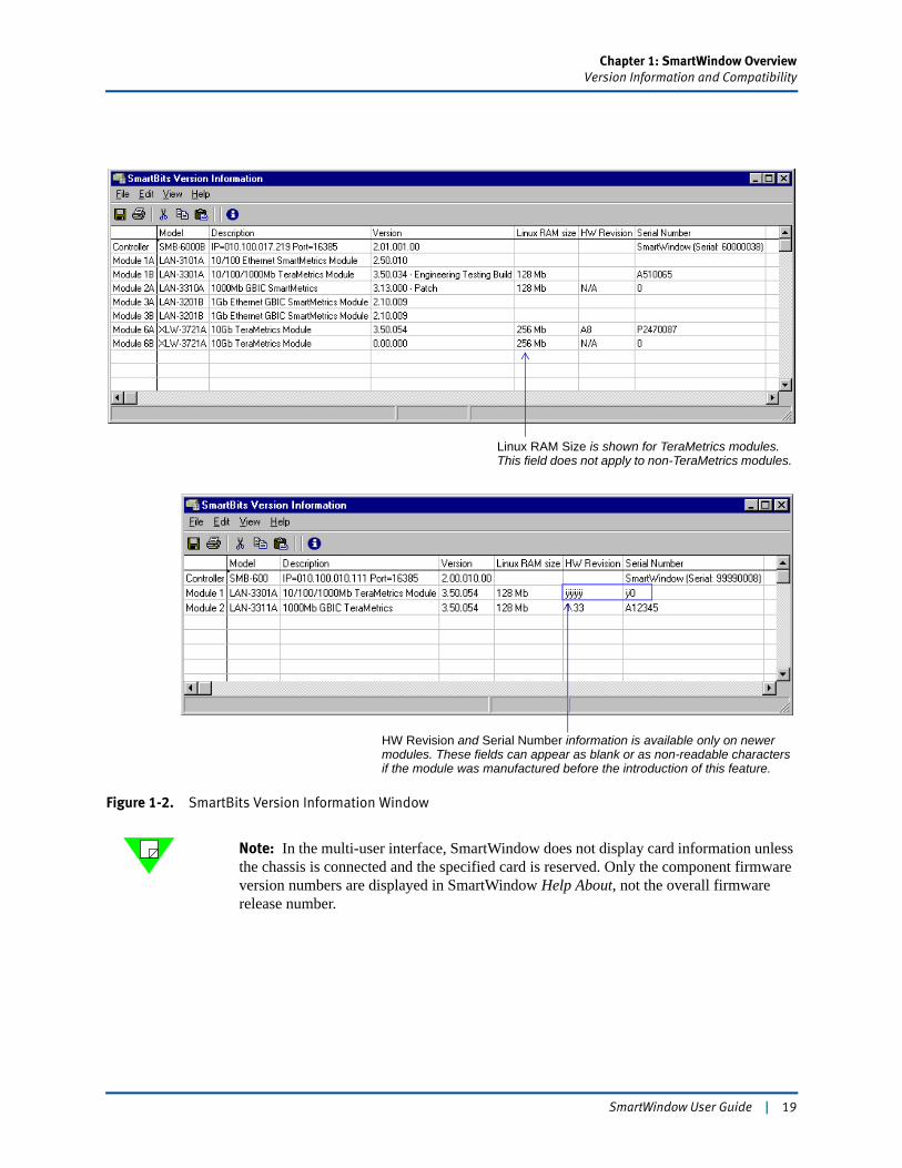
Card versions To obtain more detailed information on the SmartBits chassis and installed cards, click the Show Card Versions button. The SmartBits Version Information window opens (Figure 1-2 on page 19).
Select Show Card Versions to display version information for the chassis and its installed cards. Note: This screen shows a sample set of version/serial number information. Your screen will necessarily display information specific to your system.
18 | SmartWindow User Guide
Chapter 1: SmartWindow OverviewVersion Information and Compatibility
Figure 1-2. SmartBits Version Information Window
Note: In the multi-user interface, SmartWindow does not display card information unless the chassis is connected and the specified card is reserved. Only the component firmware version numbers are displayed in SmartWindow Help About, not the overall firmware release number.
HW Revision and Serial Number information is available only on newer modules. These fields can appear as blank or as non-readable characters if the module was manufactured before the introduction of this feature.
Linux RAM Size is shown for TeraMetrics modules. This field does not apply to non-TeraMetrics modules.
SmartWindow User Guide | 19
Chapter 1: SmartWindow OverviewWhat Are SmartCards and Modules?
What Are SmartCards and Modules?SmartCards and modules are custom-designed Printed Circuit Boards (PCBs) that are installed in a SmartBits chassis to generate, capture, and track network packet data.
• SmartCards are designed for the SmartBits 10, SmartBits 1000, and SmartBits 200/ 2000 chassis.
• Modules are designed for the SmartBits 600x/6000x chassis. Modules have a higher port density than SmartCards.
In many instances, the term card is used in this document to refer to any SmartCard or module in a SmartBits system.
SmartCards and Modules Supported
This version of SmartWindow software supports the SmartCards and modules listed in Appendix A, “Supported Cards and Modules.” Refer to the following for technical information on cards and chassis:
• SmartBits System Overview & Reference Guide
• SmartBits 200/2000 Installation Guide
• SmartBits 600x/6000x Installation Guide.
As additional cards and modules are developed for SmartBits systems, SmartWindow is updated to include support for those items.
Disk Space Requirements for Large TestsYou can simulate a large amount of network traffic by using multiple streams per card and linked SmartBits chassis. A large-scale tests consists of many ports (80 for the SmartBits 2000 and 96 for the SmartBits 6000B/6000C) and many streams (1,000 or more per port). In this case, there should be half a gigabyte of free hard disk space available.
The greater the number of streams per port and number of cards in the test, the more hard disk space is needed to store the configuration on your PC. Allow about 4.5 MB per stream.
Running histograms also adds to disk space requirements. If you plan to download histogram (chart) data, it is recommended that your PC is connected to the Ethernet port on the SmartBits chassis.
Important: Do not run other applications while running SmartBits tests since test perfor-mance might be affected.
20 | SmartWindow User Guide
Chapter 1: SmartWindow OverviewTests Described in this Guide
Tests Described in this Guide
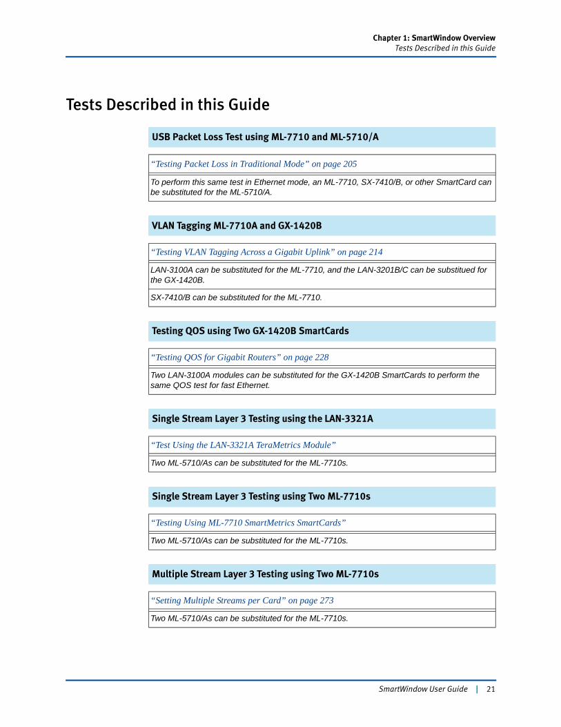
USB Packet Loss Test using ML-7710 and ML-5710/A
VLAN Tagging ML-7710A and GX-1420B
Testing QOS using Two GX-1420B SmartCards
Single Stream Layer 3 Testing using the LAN-3321A
Single Stream Layer 3 Testing using Two ML-7710s
Multiple Stream Layer 3 Testing using Two ML-7710s
“Testing Packet Loss in Traditional Mode” on page 205
To perform this same test in Ethernet mode, an ML-7710, SX-7410/B, or other SmartCard can be substituted for the ML-5710/A.
“Testing VLAN Tagging Across a Gigabit Uplink” on page 214
LAN-3100A can be substituted for the ML-7710, and the LAN-3201B/C can be substitued for the GX-1420B.
SX-7410/B can be substituted for the ML-7710.
“Testing QOS for Gigabit Routers” on page 228
Two LAN-3100A modules can be substituted for the GX-1420B SmartCards to perform the same QOS test for fast Ethernet.
“Test Using the LAN-3321A TeraMetrics Module”
Two ML-5710/As can be substituted for the ML-7710s.
“Testing Using ML-7710 SmartMetrics SmartCards”
Two ML-5710/As can be substituted for the ML-7710s.
“Setting Multiple Streams per Card” on page 273
Two ML-5710/As can be substituted for the ML-7710s.
SmartWindow User Guide | 21
Chapter 1: SmartWindow OverviewTests Described in this Guide
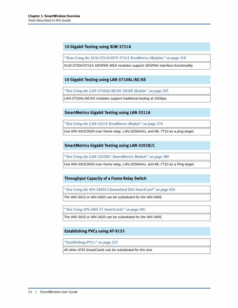
10 Gigabit Testing using XLW-3721A
10 Gigabit Testing using LAN-3710AL/AE/AS
SmartMetrics Gigabit Testing using LAN-3311A
SmartMetrics Gigabit Testing using LAN-3201B/C
Throughput Capacity of a Frame Relay Switch
Establishing PVCs using AT-9155
“Tests Using the XLW-3721A/XFP-3731A TeraMetrics Modules” on page 318
XLW-3720A/3721A XENPAK MSA modules support XENPAK interface functionality.
“Test Using the LAN-3710AL/AE/AS 10GbE Module” on page 355
LAN-3710AL/AE/AS modules support traditional testing at 10Gbps.
“Test Using the LAN-3311A TeraMetrics Module” on page 374
Use WN-3415/3420 over frame relay, LAN-3200A/AS, and ML-7710 as a ping target.
“Test Using the LAN-3201B/C SmartMetrics Module” on page 380
Use WN-3415/3420 over frame relay, LAN-3200A/AS, and ML-7710 as a Ping target.
“Test Using the WN-3445A Channelized DS3 SmartCard” on page 454
The WN-3415 or WN-3420 can be substituted for the WN-3405.
“Test Using WN-3405 T1 SmartCards” on page 492
The WN-3415 or WN-3420 can be substituted for the WN-3405.
“Establishing PVCs” on page 525
All other ATM SmartCards can be substituted for this test.
22 | SmartWindow User Guide
Chapter 1: SmartWindow OverviewTests Described in this Guide
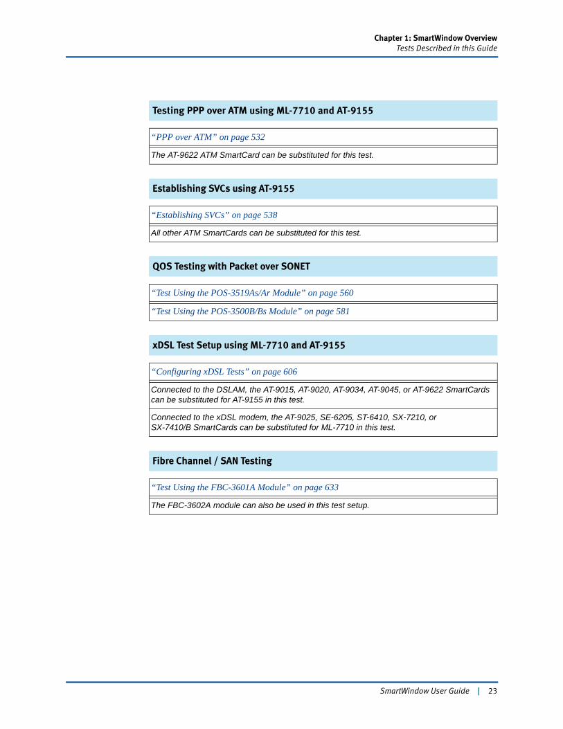
Testing PPP over ATM using ML-7710 and AT-9155
Establishing SVCs using AT-9155
QOS Testing with Packet over SONET
xDSL Test Setup using ML-7710 and AT-9155
Fibre Channel / SAN Testing
“PPP over ATM” on page 532
The AT-9622 ATM SmartCard can be substituted for this test.
“Establishing SVCs” on page 538
All other ATM SmartCards can be substituted for this test.
“Test Using the POS-3519As/Ar Module” on page 560
“Test Using the POS-3500B/Bs Module” on page 581
“Configuring xDSL Tests” on page 606
Connected to the DSLAM, the AT-9015, AT-9020, AT-9034, AT-9045, or AT-9622 SmartCards can be substituted for AT-9155 in this test.
Connected to the xDSL modem, the AT-9025, SE-6205, ST-6410, SX-7210, orSX-7410/B SmartCards can be substituted for ML-7710 in this test.
“Test Using the FBC-3601A Module” on page 633
The FBC-3602A module can also be used in this test setup.
SmartWindow User Guide | 23
Chapter 1: SmartWindow OverviewBasic Terminology in SmartBits Testing
Basic Terminology in SmartBits TestingHere is a brief list of important terms used in SmartBits testing. Refer to the SmartWindow online Help for more detailed information.
ARP Address Resolution Protocol. For IPv4-protocol data streams to be sent through a router, the SmartBits card must know the MAC address of the router port, and the router must know the MAC addresses of the SmartBits port. This information is learned by using Address Resolution Protocol (ARP) packet exchanges.
ARP maps an IP address to a MAC address. For the SmartBits port, this IP address is the address of the connected router port, not the IP destination of a packet. The router port address is specified as the default gateway. Once this value has been set (i.e., not zero), ARPs generated by the card go to this address instead of the specified IP destination address. If the gateway address is not set, the test runs as a Layer 2 test rather than a Layer 3 test.
The router also issues ARP requests to the SmartBits port. These are replied to either by the local stack or by the protocol stream, if the target IP address in the ARP request packet matches the source IP address in the stream or stack.
IP Version 6 (IPv6) streams rely upon a similar protocol (neighbor discovery) to learn the MAC addresses of neighboring routers and Layer 3 switches. Refer to “Internet Protocol, Version 6 (IPv6) Specification,” RFC 1883, December 1995 plus related RFCs and specifications for detailed information on IPv6.
background pattern
Defines the default contents of transmitted packets. It may be overwritten by Variable Field Data (VFD) fields in the frame. The default pattern is all zeros. Other patterns include incrementing, decrementing, and byte patterns such as 8-Fs / 8-0s. For example, the resulting pattern for 8-Fs / 8-0s is:
0xFF FF FF FF FF FF FF FF 00 00 00 00 00 00 00 00…
backoff trunca-tion exponent
Used to establish how long an Ethernet port waits after a collision before attempting transmission again. By default, all Ethernet SmartBits cards are configured for a backoff truncation exponent value of 10 in accordance with IEEE 802.3 standards. Smaller values result in the test port being more aggressive in a collision situation, since the truncation for backoff times starts at a lower number of successive collisions.
burst Test traffic transmitted as a set of frames followed by a period of no transmission. On a SmartBits card, bursty traffic is produced by setting an interburst gap, which is a gap size inserted in the traffic at specified intervals. Bursty test traffic simulates network traffic characterized by instances of heavy traffic interspersed with lulls. It is often used to test the buffer capabilities of a device.
24 | SmartWindow User Guide
Chapter 1: SmartWindow OverviewBasic Terminology in SmartBits Testing
jitter The variation in latency between packets in a flow. Low jitter is important in voice transmissions.
latency The time interval between the transmission and reception of a frame.
multilayer SmartCards
SmartBits cards that enable you to test the performance and interoperability of both Layer 2 (frame-based) and Layer 3 (stream-based) devices as well as Layer 4 operations. A multilayer card can generate mixed-protocol traffic equivalent to one fully loaded LAN with up to 1000 end-user devices. Multilayer cards include the ML-7710 and ML-5710/A.
transmit modes
The method for sending test traffic.
• Continuous ModeTransmits a constant stream of packets at the user-selected interpacket gap.
• Single Burst ModeTransmits a single burst at the user-selected interpacket gap.
• Multiburst ModeRepetitive bursts with a user-adjustable delay between each burst.
• Echo ModeSends one packet when a trigger occurs.
• Continuous Multiburst ModeRuns multiburst mode continuously.
triggers A pattern-counting tool used by the receiving SmartBits card to mark any packet that contains a specified trigger pattern. SmartBits applications automatically insert triggers and can also insert user-selectable errors.
VFD Variable Field Definition. A field within the test frame whose contents and value can be manipulated—for example, incremented, decremented, or used in segments, frame by frame. Variable Field Definitions (VFDs) are written over the specified background fill pattern and can change on a per-frame basis at wire speeds. VFDs are used in the traditional mode and are available on Ethernet cards and WAN cards.
VTE Virtual Transmit Engine. A configurable software “engine” that generates one stream of test traffic. It is “network-protocol aware” and can conform to any standard network protocol, such as IP or UDP, or have a user-defined protocol assignment. A Virtual Transmit Engine (VTE) and its related stream are interdependent; the VTE is the software mechanism that creates the stream. The stream is the generated output.
SmartWindow User Guide | 25

26 | SmartWindow User Guide
Chapter 2
Install and Connect
Install SmartWindow over a network or from a CD.
In this chapter...
• Installing SmartWindow . . . . 28
• Starting SmartWindow . . . . 31
• Setting up a Connection . . . . 42
SmartWindow User Guide | 27
Chapter 2: Install and ConnectInstalling SmartWindow
Installing SmartWindowAn executable file on the installation disk handles the details of the installation.
PC Workstation Requirements
To install and use SmartWindow, the following PC hardware and software are required. Review these requirements carefully to ensure successful installation.
Note: For detailed SmartBits system requirements, refer to the SmartBits 200/2000 Installation Guide or SmartBits 600x/6000x Installation Guide, as appropriate.
• IBM compatible PC (400 MHz Pentium III recommended) with the following:• One 10/100Base-T UTP cable and a 10/100 Mbps Ethernet NIC installed in the
PC• Minimum 128 MB RAM; 1 GB RAM recommended (128 MB is acceptable if
tests involve a small number of streams)• Minimum 50 MB hard drive space; minimum 4 GB hard drive recommended
Note: For disk space requirements for tests, see “Disk Space Requirements for Large Tests” on page 47.
• A 3.5-inch high-density floppy disk drive, a mouse, and an SVGA color monitor or equivalent
• Serial port capable of running at least 38,400 bps
• RS-232 straight-through cable with a DB-25 female connector to attach to the SmartBits chassis, and either a DB-9 or DB-25 female connector to attach to the PC
• CD-ROM drive
• Microsoft Windows 2000 Pro SP4 or Windows XP SP1, 1a, or 2
• Microsoft Terminal, HyperTerminal, or other communications program
• Adobe Acrobat Reader 5.0 or later, to print user documentation
Note: To connect the SmartBits chassis directly to a PC via Ethernet, an Ethernet crossover cable (available as a SmartBits accessory or at any computer store) is required.
28 | SmartWindow User Guide
Chapter 2: Install and ConnectInstalling SmartWindow
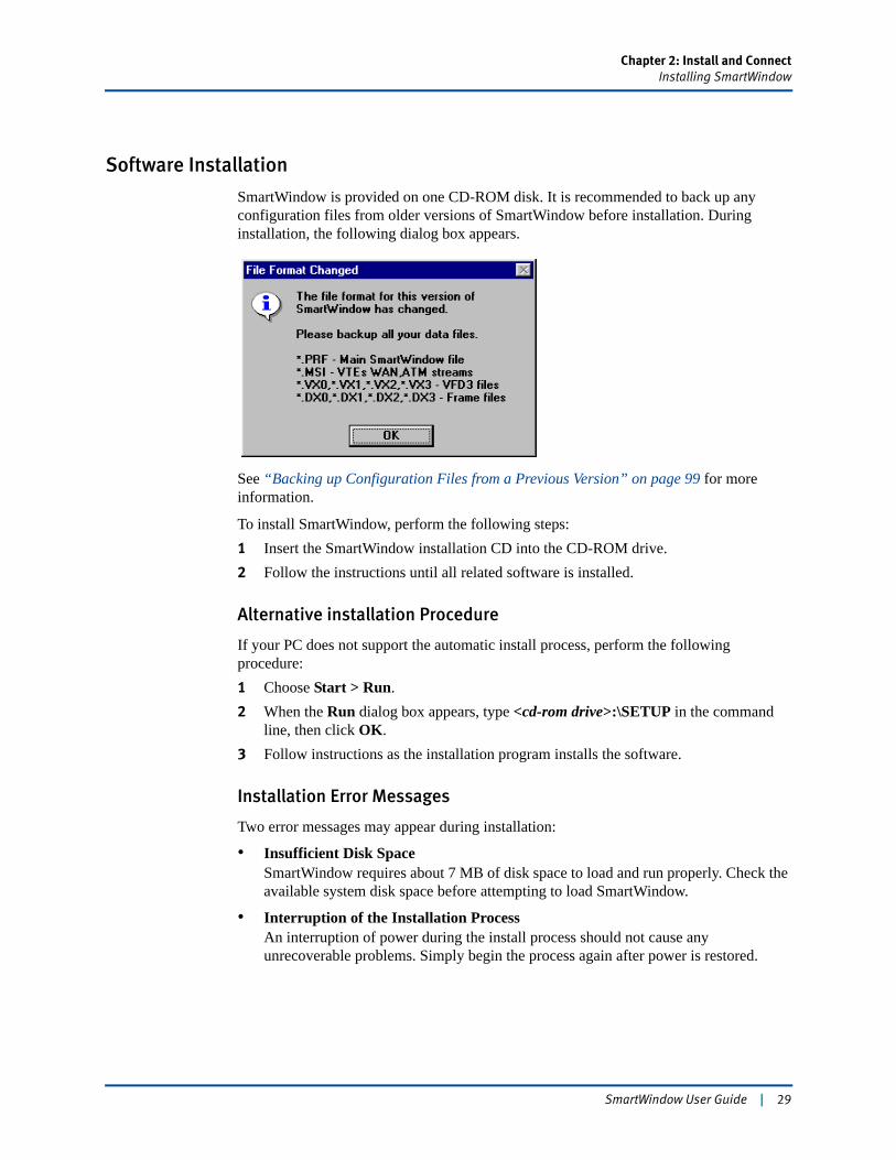
Software Installation
SmartWindow is provided on one CD-ROM disk. It is recommended to back up any configuration files from older versions of SmartWindow before installation. During installation, the following dialog box appears.
See “Backing up Configuration Files from a Previous Version” on page 99 for more information.
To install SmartWindow, perform the following steps:1 Insert the SmartWindow installation CD into the CD-ROM drive.2 Follow the instructions until all related software is installed.
Alternative installation Procedure
If your PC does not support the automatic install process, perform the following procedure:1 Choose Start > Run.2 When the Run dialog box appears, type <cd-rom drive>:\SETUP in the command
line, then click OK.3 Follow instructions as the installation program installs the software.
Installation Error Messages
Two error messages may appear during installation:
• Insufficient Disk SpaceSmartWindow requires about 7 MB of disk space to load and run properly. Check the available system disk space before attempting to load SmartWindow.
• Interruption of the Installation ProcessAn interruption of power during the install process should not cause any unrecoverable problems. Simply begin the process again after power is restored.
SmartWindow User Guide | 29
Chapter 2: Install and ConnectInstalling SmartWindow
Testing with Multiple SmartBits Chassis
Important: When using a multiple chassis arrangement that contains SmartBits 600x/6000x chassis, you must use a synchronous, CAT-5, straight-through (not crossover) cable to connect the chassis together. The cable should be 1m or less in length. (An appropriate synchronous, CAT-5, straight-through cable is shipped with your SmartBits chassis.) The use of the synchronous cable is required for overall test results to be accurate (not just latency test results, but all test results).
In addition, all chassis in the arrangement must be booted in the proper order. First boot the chassis that contains the master clock. Next, wait 10 seconds and then boot the next chassis in the chain. Wait another 10 seconds and then boot the next chassis, etc. It is important to wait 10 seconds before booting the next chassis in line.
For detailed information on multiple chassis operation, refer to the SmartBits 200/2000 Installation Guide or the SmartBits 600x/6000x Installation Guide.
30 | SmartWindow User Guide
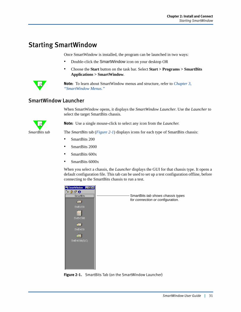
Chapter 2: Install and ConnectStarting SmartWindow
Starting SmartWindowOnce SmartWindow is installed, the program can be launched in two ways:
• Double-click the SmartWindow icon on your desktop OR
• Choose the Start button on the task bar. Select Start > Programs > SmartBits Applications > SmartWindow.
Note: To learn about SmartWindow menus and structure, refer to Chapter 3, “SmartWindow Menus.”
SmartWindow Launcher
When SmartWindow opens, it displays the SmartWindow Launcher. Use the Launcher to select the target SmartBits chassis.
Note: Use a single mouse-click to select any icon from the Launcher.
SmartBits tab The SmartBits tab (Figure 2-1) displays icons for each type of SmartBits chassis:
• SmartBits 200
• SmartBits 2000
• SmartBits 600x
• SmartBits 6000x
When you select a chassis, the Launcher displays the GUI for that chassis type. It opens a default configuration file. This tab can be used to set up a test configuration offline, before connecting to the SmartBits chassis to run a test.
Figure 2-1. SmartBits Tab (on the SmartWindow Launcher)
SmartBits tab shows chassis typesfor connection or configuration.
SmartWindow User Guide | 31
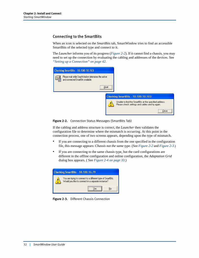
Chapter 2: Install and ConnectStarting SmartWindow
Connecting to the SmartBits
When an icon is selected on the SmartBits tab, SmartWindow tries to find an accessible SmartBits of the selected type and connect to it.
The Launcher informs you of its progress (Figure 2-2). If it cannot find a chassis, you may need to set up the connection by evaluating the cabling and addresses of the devices. See “Setting up a Connection” on page 42.
Figure 2-2. Connection Status Messages (SmartBits Tab)
If the cabling and address structure is correct, the Launcher then validates the configuration file to determine where the mismatch is occurring. At this point in the connection process, one of two screens appears, depending upon the type of mismatch.
• If you are connecting to a different chassis from the one specified in the configuration file, this message appears: Chassis not the same type. (See Figure 2-2 and Figure 2-3.)
• If you are connecting to the same chassis type, but the card configurations are different in the offline configuration and online configuration, the Adaptation Grid dialog box appears. ( See Figure 2-4 on page 33.)
Figure 2-3. Different Chassis Connection
32 | SmartWindow User Guide
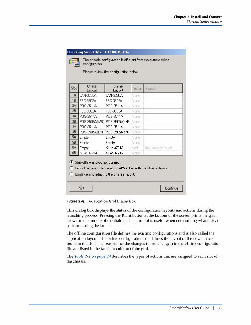
Chapter 2: Install and ConnectStarting SmartWindow
Figure 2-4. Adaptation Grid Dialog Box
This dialog box displays the status of the configuration layouts and actions during the launching process. Pressing the Print button at the bottom of the screen prints the grid shown in the middle of the dialog. This printout is useful when determining what tasks to perform during the launch.
The offline configuration file defines the existing configurations and is also called the application layout. The online configuration file defines the layout of the new device found in the slot. The reasons for the changes (or no changes) in the offline configuration file are listed in the far right column of the grid.
The Table 2-1 on page 34 describes the types of actions that are assigned to each slot of the chassis.
SmartWindow User Guide | 33
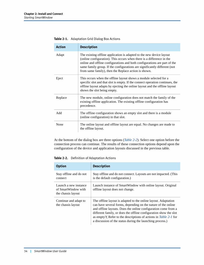
Chapter 2: Install and ConnectStarting SmartWindow
At the bottom of the dialog box are three options (Table 2-2). Select one option before the connection process can continue. The results of these connection options depend upon the configuration of the device and application layouts discussed in the previous table.
Table 2-1. Adaptation Grid Dialog Box Actions
Action Description
Adapt The existing offline application is adapted to the new device layout (online configuration). This occurs when there is a difference in the online and offline configurations and both configurations are part of the same family group. If the configurations are significantly different (not from same family), then the Replace action is shown.
Eject This occurs when the offline layout shows a module selected for a specific slot and that slot is empty. If the connect operation continues, the offline layout adapts by ejecting the online layout and the offline layout shows the slot being empty.
Replace The new module, online configuration does not match the family of the existing offline application. The existing offline configuration has precedence.
Add The offline configuration shows an empty slot and there is a module (online configuration) in that slot.
None The online layout and offline layout are equal. No changes are made to the offline layout.
Table 2-2. Definition of Adaptation Actions
Option Description
Stay offline and do not connect
Stay offline and do not connect. Layouts are not impacted. (This is the default configuration.)
Launch a new instance of SmartWindow with the chassis layout
Launch instance of SmartWindow with online layout. Original offline layout does not change.
Continue and adapt to the chassis layout
The offline layout is adapted to the online layout. Adaptation can have several forms, depending on the nature of the online and offline layouts. Does the online configuration come from a different family, or does the offline configuration show the slot as empty?( Refer to the descriptions of actions in Table 2-1 for a discussion of the status during the launching process.)
34 | SmartWindow User Guide
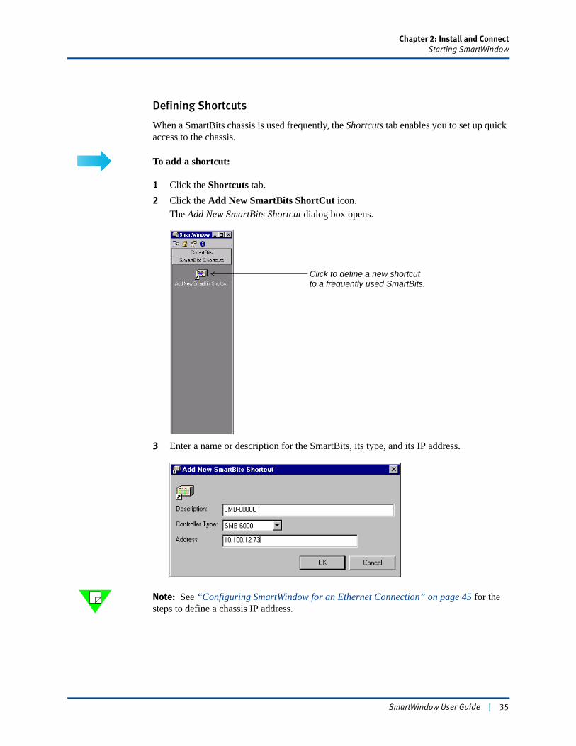
Chapter 2: Install and ConnectStarting SmartWindow
Defining Shortcuts
When a SmartBits chassis is used frequently, the Shortcuts tab enables you to set up quick access to the chassis.
To add a shortcut:
1 Click the Shortcuts tab.2 Click the Add New SmartBits ShortCut icon.
The Add New SmartBits Shortcut dialog box opens.
3 Enter a name or description for the SmartBits, its type, and its IP address.
Note: See “Configuring SmartWindow for an Ethernet Connection” on page 45 for the steps to define a chassis IP address.
Click to define a new shortcutto a frequently used SmartBits.
SmartWindow User Guide | 35

Chapter 2: Install and ConnectStarting SmartWindow
To delete a shortcut:
1 Right-click the icon to be deleted.2 Select Delete from the drop-down menu.
36 | SmartWindow User Guide
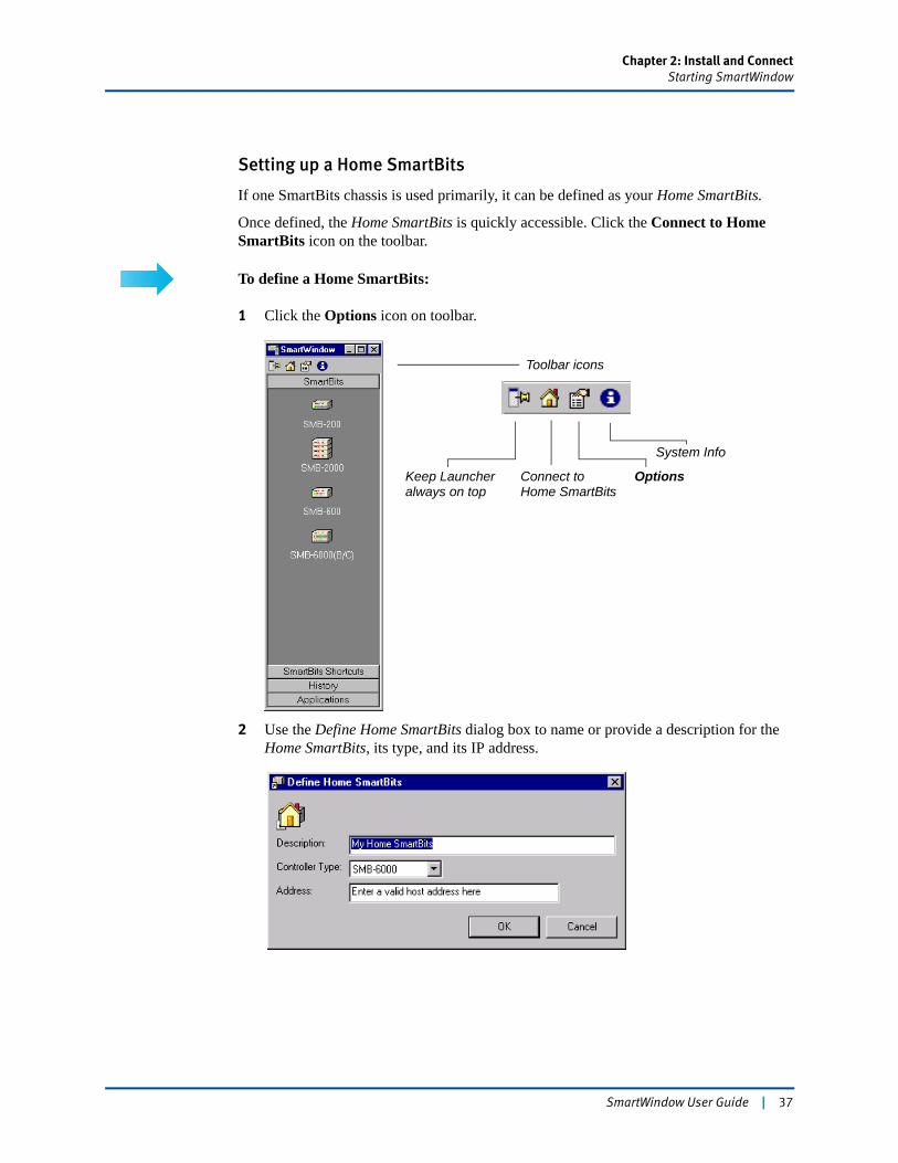
Chapter 2: Install and ConnectStarting SmartWindow
Setting up a Home SmartBits
If one SmartBits chassis is used primarily, it can be defined as your Home SmartBits.
Once defined, the Home SmartBits is quickly accessible. Click the Connect to Home SmartBits icon on the toolbar.
To define a Home SmartBits:
1 Click the Options icon on toolbar.
2 Use the Define Home SmartBits dialog box to name or provide a description for the Home SmartBits, its type, and its IP address.
Toolbar icons
Keep Launcheralways on top
Connect toHome SmartBits
Options
System Info
SmartWindow User Guide | 37

Chapter 2: Install and ConnectStarting SmartWindow
History Tab
Use the History tab to review recent connections.
Click an icon to open the history list for a specified day or week.
Figure 2-5. History Tab
Click an entry to connect to the SmartBits.
38 | SmartWindow User Guide
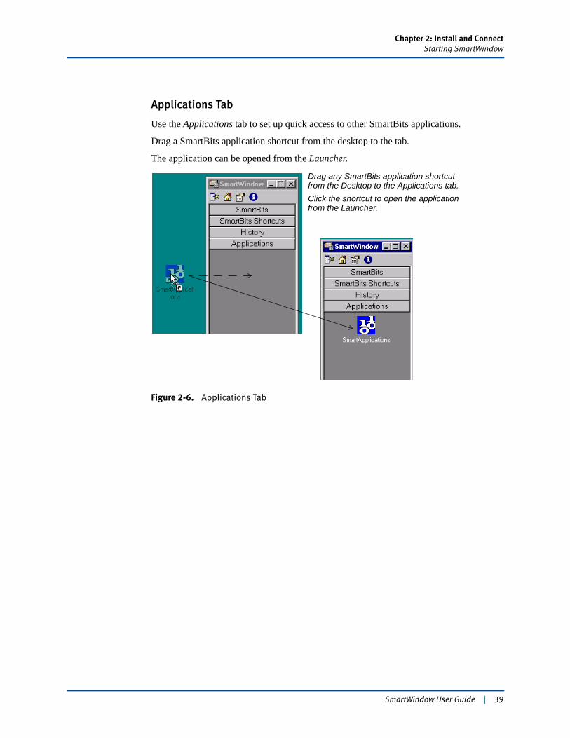
Chapter 2: Install and ConnectStarting SmartWindow
Applications Tab
Use the Applications tab to set up quick access to other SmartBits applications.
Drag a SmartBits application shortcut from the desktop to the tab.
The application can be opened from the Launcher.
Figure 2-6. Applications Tab
Drag any SmartBits application shortcut from the Desktop to the Applications tab.Click the shortcut to open the application from the Launcher.
SmartWindow User Guide | 39
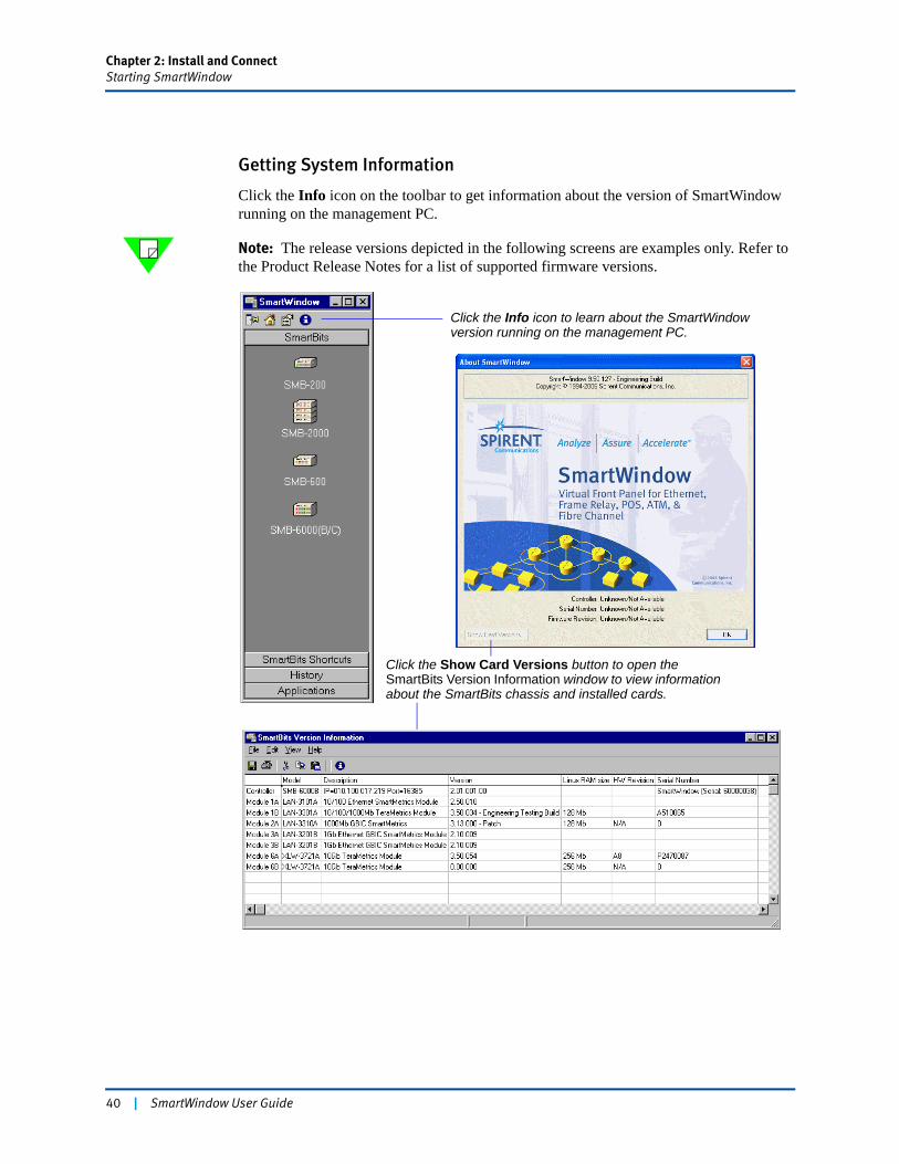
Chapter 2: Install and ConnectStarting SmartWindow
Getting System Information
Click the Info icon on the toolbar to get information about the version of SmartWindow running on the management PC.
Note: The release versions depicted in the following screens are examples only. Refer to the Product Release Notes for a list of supported firmware versions.
Click the Info icon to learn about the SmartWindow version running on the management PC.
Click the Show Card Versions button to open the SmartBits Version Information window to view information about the SmartBits chassis and installed cards.
40 | SmartWindow User Guide
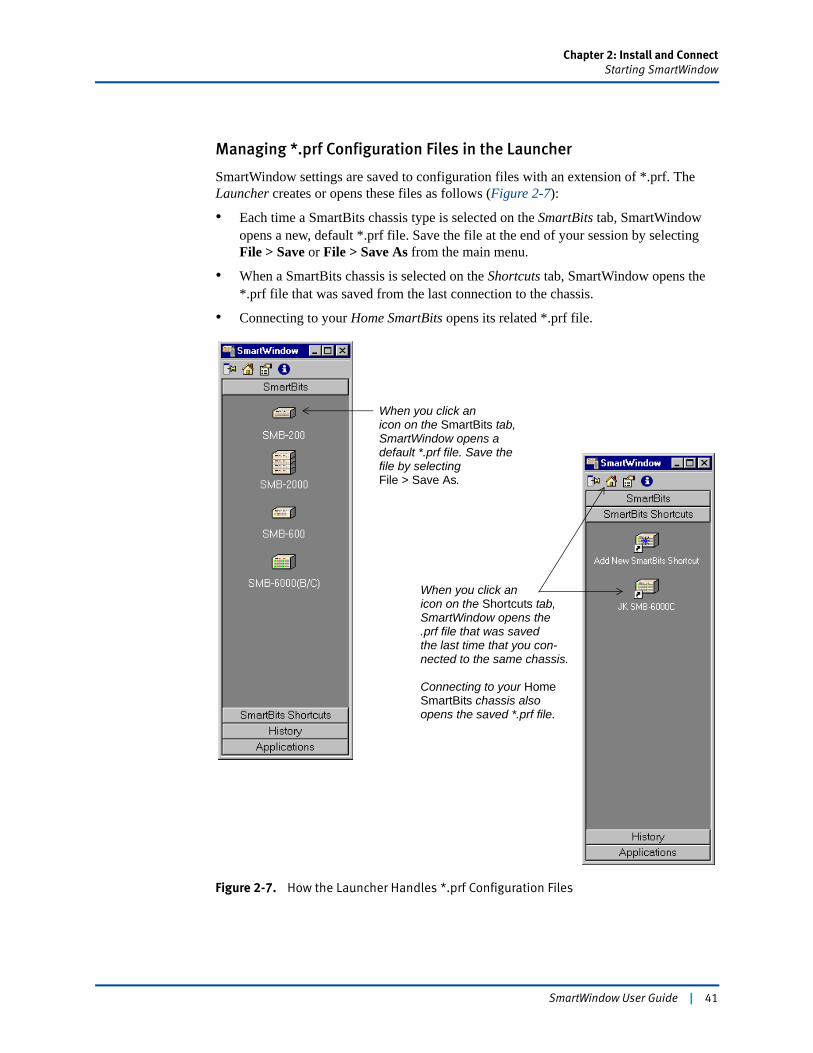
Chapter 2: Install and ConnectStarting SmartWindow
Managing *.prf Configuration Files in the Launcher
SmartWindow settings are saved to configuration files with an extension of *.prf. The Launcher creates or opens these files as follows (Figure 2-7):
• Each time a SmartBits chassis type is selected on the SmartBits tab, SmartWindow opens a new, default *.prf file. Save the file at the end of your session by selecting File > Save or File > Save As from the main menu.
• When a SmartBits chassis is selected on the Shortcuts tab, SmartWindow opens the *.prf file that was saved from the last connection to the chassis.
• Connecting to your Home SmartBits opens its related *.prf file.
Figure 2-7. How the Launcher Handles *.prf Configuration Files
When you click anicon on the SmartBits tab,SmartWindow opens adefault *.prf file. Save thefile by selectingFile > Save As.
When you click anicon on the Shortcuts tab,SmartWindow opens the.prf file that was savedthe last time that you con-nected to the same chassis.
Connecting to your HomeSmartBits chassis alsoopens the saved *.prf file.
SmartWindow User Guide | 41
Chapter 2: Install and ConnectSetting up a Connection
Setting up a ConnectionThe SmartBits 200/2000 Installation Guide and SmartBits 600x/6000x Installation Guide describe how to make a connection from your PC to a SmartBits chassis. Two connection methods are possible:
• SerialUsed only with SmartBits 200 and SmartBits 2000. (This is the default.) Used for point-to-point connections. (See “Initial SmartBits Configuration” on page 42.)
• EthernetUsed with SmartBits 200/2000 and SmartBits 600x/6000x. Requires a Network Interface Card (NIC) in your PC. Enables you to connect SmartWindow to the SmartBits chassis over an Ethernet connection (including the Internet) from your PC. (See “Configuring SmartWindow for an Ethernet Connection” on page 45.)
Initial SmartBits ConfigurationWith an unconfigured SmartBits 200/2000, you can only use a serial connection to connect to the PC because SmartBits does not yet have an IP address.Use SmartWindow to set the initial IP address. To do this, verify that you are using the appropriate serial cable. (Refer to SmartBits 200/2000 Installation Guide for cabling information.)
For the SmartBits 600x/6000x, initial IP address configuration is set through HyperTerminal.1
You must be offline to access the Connection Setup menu. Connection status is shown as OnLine or OffLine on the SmartWindow status bar.
To configure a SmartBits 200/2000:
1 Choose Options > Connection Setup.2 Click the Use Serial Port button.
The following fields become enabled.
Port Select the COM port that was used to connect the PC to the SmartBits. By default, the Port list shows only available COM ports. If the list does not include an installed COM port (e.g., COM1), this situation may be caused by the following:
1. The SmartBits 600x/6000x does not allow a serial connection through SmartWindow or other Spirent applications. (See SmartBits 600x/6000x Installation Guide for information on how to configure the IP address.)
42 | SmartWindow User Guide
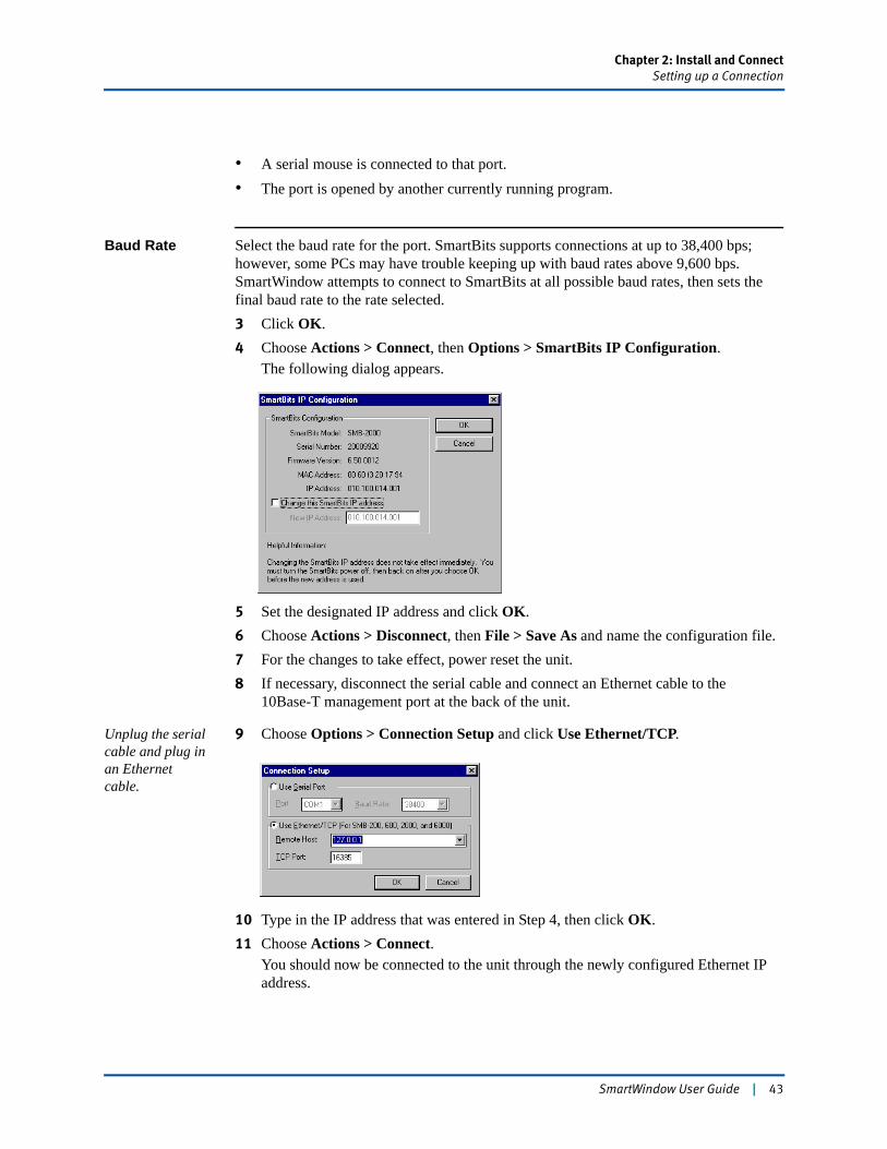
Chapter 2: Install and ConnectSetting up a Connection
• A serial mouse is connected to that port.• The port is opened by another currently running program.
Baud Rate Select the baud rate for the port. SmartBits supports connections at up to 38,400 bps; however, some PCs may have trouble keeping up with baud rates above 9,600 bps. SmartWindow attempts to connect to SmartBits at all possible baud rates, then sets the final baud rate to the rate selected.3 Click OK.4 Choose Actions > Connect, then Options > SmartBits IP Configuration.
The following dialog appears.
5 Set the designated IP address and click OK.6 Choose Actions > Disconnect, then File > Save As and name the configuration file.7 For the changes to take effect, power reset the unit.8 If necessary, disconnect the serial cable and connect an Ethernet cable to the
10Base-T management port at the back of the unit.
Unplug the serial cable and plug in an Ethernet cable.
9 Choose Options > Connection Setup and click Use Ethernet/TCP.
10 Type in the IP address that was entered in Step 4, then click OK.11 Choose Actions > Connect.
You should now be connected to the unit through the newly configured Ethernet IP address.
SmartWindow User Guide | 43
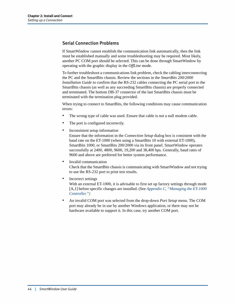
Chapter 2: Install and ConnectSetting up a Connection
Serial Connection Problems
If SmartWindow cannot establish the communication link automatically, then the link must be established manually and some troubleshooting may be required. Most likely, another PC COM port should be selected. This can be done through SmartWindow by operating with the graphic display in the OffLine mode.
To further troubleshoot a communications link problem, check the cabling interconnecting the PC and the SmartBits chassis. Review the sections in the SmartBits 200/2000 Installation Guide to confirm that the RS-232 cables connecting the PC serial port to the SmartBits chassis (as well as any succeeding SmartBits chassis) are properly connected and terminated. The bottom DB-37 connector of the last SmartBits chassis must be terminated with the termination plug provided.
When trying to connect to SmartBits, the following conditions may cause communication errors:
• The wrong type of cable was used. Ensure that cable is not a null modem cable.
• The port is configured incorrectly.
• Inconsistent setup informationEnsure that the information in the Connection Setup dialog box is consistent with the baud rate on the ET-1000 (when using a SmartBits 10 with external ET-1000), SmartBits 1000, or SmartBits 200/2000 via its front panel. SmartWindow operates successfully at 2400, 4800, 9600, 19,200 and 38,400 bps. Generally, baud rates of 9600 and above are preferred for better system performance.
• Invalid communicationCheck that the SmartBits chassis is communicating with SmartWindow and not trying to use the RS-232 port to print test results.
• Incorrect settingsWith an external ET-1000, it is advisable to first set up factory settings through mode [A,1] before specific changes are installed. (See Appendix C, “Managing the ET-1000 Controller.”)
• An invalid COM port was selected from the drop-down Port Setup menu. The COM port may already be in use by another Windows application, or there may not be hardware available to support it. In this case, try another COM port.
44 | SmartWindow User Guide
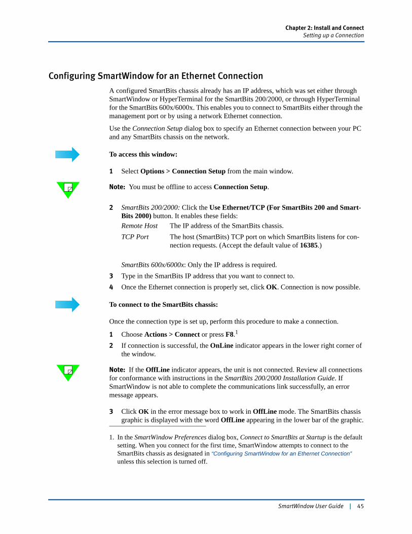
Chapter 2: Install and ConnectSetting up a Connection
Configuring SmartWindow for an Ethernet Connection
A configured SmartBits chassis already has an IP address, which was set either through SmartWindow or HyperTerminal for the SmartBits 200/2000, or through HyperTerminal for the SmartBits 600x/6000x. This enables you to connect to SmartBits either through the management port or by using a network Ethernet connection.
Use the Connection Setup dialog box to specify an Ethernet connection between your PC and any SmartBits chassis on the network.
To access this window:
1 Select Options > Connection Setup from the main window.
Note: You must be offline to access Connection Setup.
2 SmartBits 200/2000: Click the Use Ethernet/TCP (For SmartBits 200 and Smart-Bits 2000) button. It enables these fields:Remote Host The IP address of the SmartBits chassis.TCP Port The host (SmartBits) TCP port on which SmartBits listens for con-
nection requests. (Accept the default value of 16385.)
SmartBits 600x/6000x: Only the IP address is required.3 Type in the SmartBits IP address that you want to connect to.4 Once the Ethernet connection is properly set, click OK. Connection is now possible.
To connect to the SmartBits chassis:
Once the connection type is set up, perform this procedure to make a connection.
1 Choose Actions > Connect or press F8.1
2 If connection is successful, the OnLine indicator appears in the lower right corner of the window.
Note: If the OffLine indicator appears, the unit is not connected. Review all connections for conformance with instructions in the SmartBits 200/2000 Installation Guide. If SmartWindow is not able to complete the communications link successfully, an error message appears.
3 Click OK in the error message box to work in OffLine mode. The SmartBits chassis graphic is displayed with the word OffLine appearing in the lower bar of the graphic.
1. In the SmartWindow Preferences dialog box, Connect to SmartBits at Startup is the default setting. When you connect for the first time, SmartWindow attempts to connect to the SmartBits chassis as designated in “Configuring SmartWindow for an Ethernet Connection” unless this selection is turned off.
SmartWindow User Guide | 45
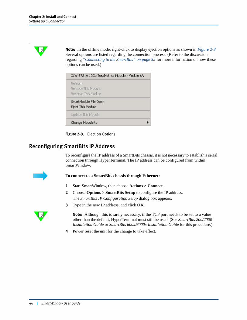
Chapter 2: Install and ConnectSetting up a Connection
e
Note: In the offline mode, right-click to display ejection options as shown in Figure 2-8. Several options are listed regarding the connection process. (Refer to the discussion regarding “Connecting to the SmartBits” on page 32 for more information on how these options can be used.)
Figure 2-8. Ejection Options
Reconfiguring SmartBits IP Address
To reconfigure the IP address of a SmartBits chassis, it is not necessary to establish a serial connection through HyperTerminal. The IP address can be configured from within SmartWindow.
To connect to a SmartBits chassis through Ethernet:
1 Start SmartWindow, then choose Actions > Connect.2 Choose Options > SmartBits Setup to configure the IP address.
The SmartBits IP Configuration Setup dialog box appears.3 Type in the new IP address, and click OK.
Note: Although this is rarely necessary, if the TCP port needs to be set to a value other than the default, HyperTerminal must still be used. (See SmartBits 200/2000 Installation Guide or SmartBits 600x/6000x Installation Guide for this procedure.)
4 Power reset the unit for the change to take effect.
46 | SmartWindow User Guide
Chapter 2: Install and ConnectSetting up a Connection
Disk Space Requirements for Large Tests
A large amount of network traffic can be simulated by using multiple streams per card and linked SmartBits chassis. A large-scale test consists of many ports (80 for the SmartBits 2000 and 96 for the SmartBits 600x/6000x) and many streams (1,000 or more per port). For any tests of this scale, have at least 0.50 Gigabyte (500 Mbytes) of hard disk space available for use.
The greater the number of streams per card and number of cards, the more hard disk space is needed to store the configuration on the PC. Specifically, about 4.5 Mb of disk space per stream is required. Running histograms also increases disk space requirements.
Note: If you plan to download histogram (chart) data, connect your PC to the Ethernet port on the SmartBits chassis. This connection provides higher data transfer rates.
Important: Do not run other applications that might affect performance during a test.
SmartWindow User Guide | 47

48 | SmartWindow User Guide

Chapter 3
SmartWindow Menus
The salient feature of SmartWindow is its dynamic menu system. No matter what SmartBits chassis is connected, SmartWindow displays a virtual front panel for the chassis and its installed cards.
In this chapter...
• SmartWindow User Interface . . . . 50
• File Menu . . . . 55
• Edit Menu . . . . 56
• Actions Menu . . . . 59
• Options Menu . . . . 62
• Tests Menu . . . . 70
• Admin Menu . . . . 71
• View Menu . . . . 74
• Help Menu . . . . 75
SmartWindow User Guide | 49
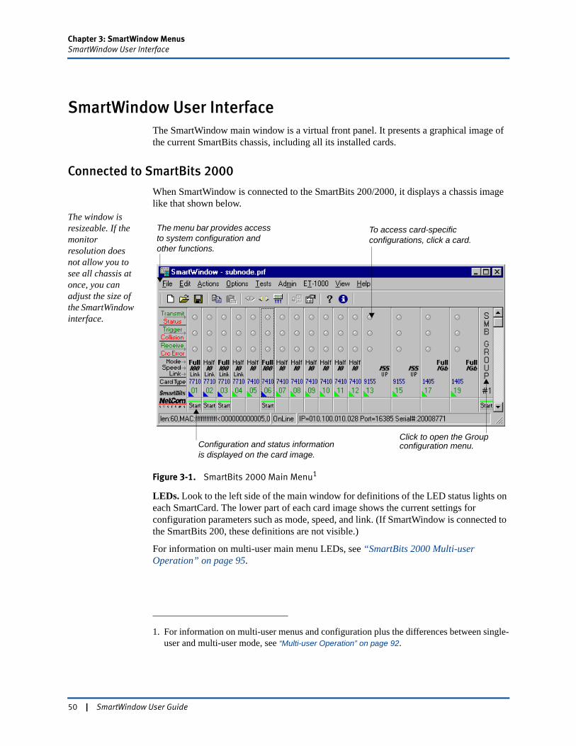
Chapter 3: SmartWindow MenusSmartWindow User Interface
SmartWindow User InterfaceThe SmartWindow main window is a virtual front panel. It presents a graphical image of the current SmartBits chassis, including all its installed cards.
Connected to SmartBits 2000
When SmartWindow is connected to the SmartBits 200/2000, it displays a chassis image like that shown below.
The window is resizeable. If the monitor resolution does not allow you to see all chassis at once, you can adjust the size of the SmartWindow interface.
Figure 3-1. SmartBits 2000 Main Menu1
LEDs. Look to the left side of the main window for definitions of the LED status lights on each SmartCard. The lower part of each card image shows the current settings for configuration parameters such as mode, speed, and link. (If SmartWindow is connected to the SmartBits 200, these definitions are not visible.)
For information on multi-user main menu LEDs, see “SmartBits 2000 Multi-user Operation” on page 95.
1. For information on multi-user menus and configuration plus the differences between single-user and multi-user mode, see “Multi-user Operation” on page 92.
Click to open the Group
The menu bar provides access to system configuration and other functions.
To access card-specific configurations, click a card.
Configuration and status information is displayed on the card image.
configuration menu.
50 | SmartWindow User Guide
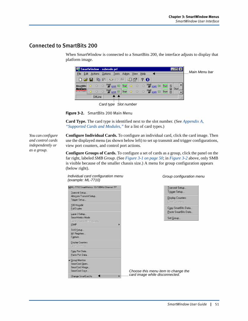
Chapter 3: SmartWindow MenusSmartWindow User Interface
Connected to SmartBits 200
When SmartWindow is connected to a SmartBits 200, the interface adjusts to display that platform image.
Figure 3-2. SmartBits 200 Main Menu
Card Type. The card type is identified next to the slot number. (See Appendix A, “Supported Cards and Modules,” for a list of card types.)
You can configure and control cards independently or as a group.
Configure Individual Cards. To configure an individual card, click the card image. Then use the displayed menu (as shown below left) to set up transmit and trigger configurations, view port counters, and control port actions.
Configure Groups of Cards. To configure a set of cards as a group, click the panel on the far right, labeled SMB Group. (See Figure 3-1 on page 50; in Figure 3-2 above, only SMB is visible because of the smaller chassis size.) A menu for group configuration appears (below right).
Main Menu bar
Card type Slot number
Individual card configuration menu(example: ML-7710)
Group configuration menu
Choose this menu item to change thecard image while disconnected.
SmartWindow User Guide | 51
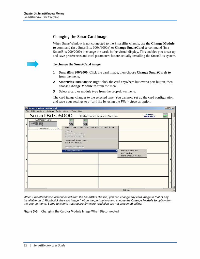
Chapter 3: SmartWindow MenusSmartWindow User Interface
Changing the SmartCard Image
When SmartWindow is not connected to the SmartBits chassis, use the Change Module to command (in a SmartBits 600x/6000x) or Change SmartCard to command (in a SmartBits 200/2000) to change the cards in the virtual display. This enables you to set up and save preferences and card parameters before actually installing the SmartBits system.
To change the SmartCard image:
1 SmartBits 200/2000: Click the card image, then choose Change SmartCards to from the menu.
2 SmartBits 600x/6000x: Right-click the card anywhere but over a port button, then choose Change Module to from the menu.
3 Select a card or module type from the drop-down menu.
The card image changes to the selected type. You can now set up the card configuration and save your settings to a *.prf file by using the File > Save as option.
Figure 3-3. Changing the Card or Module Image When Disconnected
When SmartWindow is disconnected from the SmartBits chassis, you can change any card image to that of any installable card. Right-click the card image (not on the port button) and choose the Change Module to option from the pop-up menu. Some functions that require firmware validation are not presented offline.
52 | SmartWindow User Guide
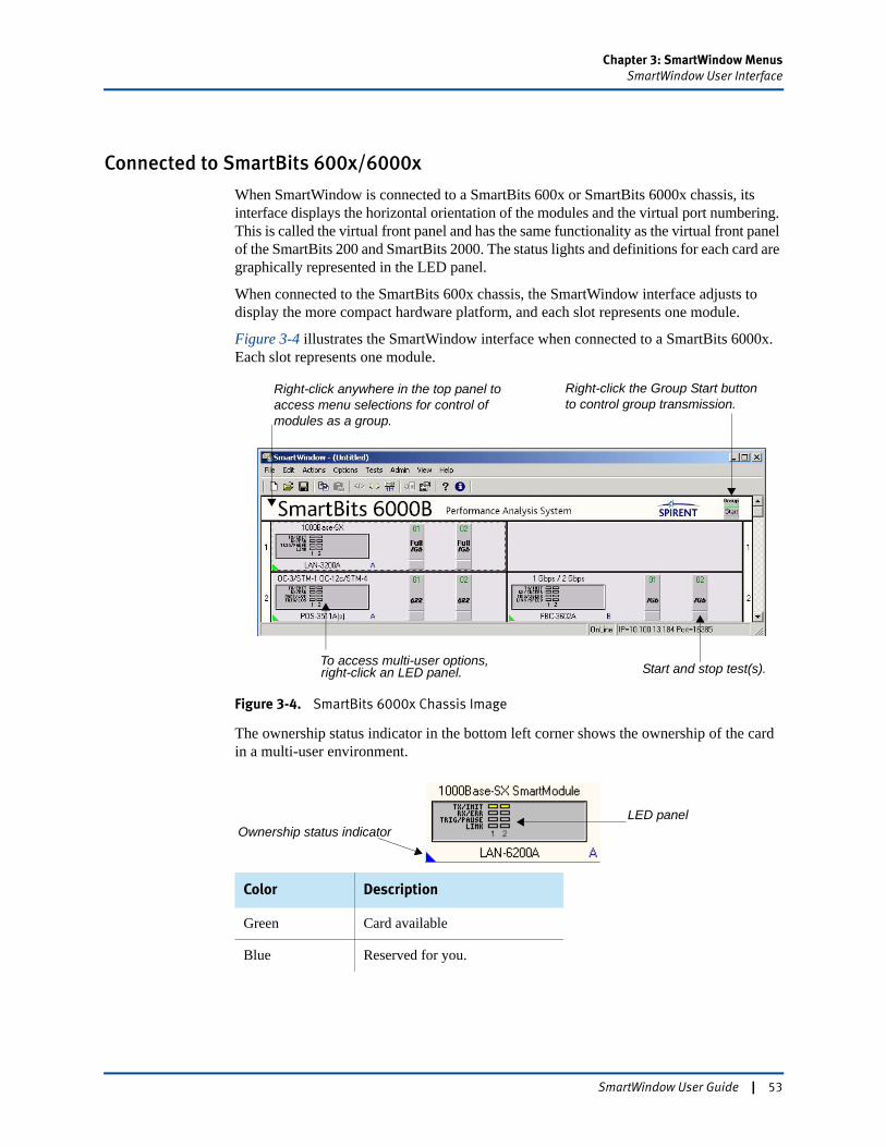
Chapter 3: SmartWindow MenusSmartWindow User Interface
Connected to SmartBits 600x/6000x
When SmartWindow is connected to a SmartBits 600x or SmartBits 6000x chassis, its interface displays the horizontal orientation of the modules and the virtual port numbering. This is called the virtual front panel and has the same functionality as the virtual front panel of the SmartBits 200 and SmartBits 2000. The status lights and definitions for each card are graphically represented in the LED panel.
When connected to the SmartBits 600x chassis, the SmartWindow interface adjusts to display the more compact hardware platform, and each slot represents one module.
Figure 3-4 illustrates the SmartWindow interface when connected to a SmartBits 6000x. Each slot represents one module.
Figure 3-4. SmartBits 6000x Chassis Image
The ownership status indicator in the bottom left corner shows the ownership of the card in a multi-user environment.
Color Description
Green Card available
Blue Reserved for you.
To access multi-user options,
Right-click anywhere in the top panel to access menu selections for control of modules as a group.
Right-click the Group Start button to control group transmission.
right-click an LED panel. Start and stop test(s).
LED panelOwnership status indicator
SmartWindow User Guide | 53
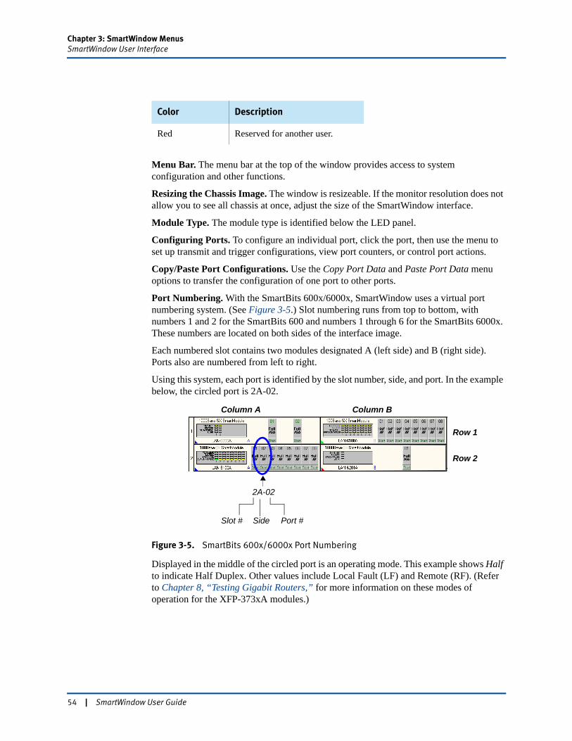
Chapter 3: SmartWindow MenusSmartWindow User Interface
Menu Bar. The menu bar at the top of the window provides access to system configuration and other functions.
Resizing the Chassis Image. The window is resizeable. If the monitor resolution does not allow you to see all chassis at once, adjust the size of the SmartWindow interface.
Module Type. The module type is identified below the LED panel.
Configuring Ports. To configure an individual port, click the port, then use the menu to set up transmit and trigger configurations, view port counters, or control port actions.
Copy/Paste Port Configurations. Use the Copy Port Data and Paste Port Data menu options to transfer the configuration of one port to other ports.
Port Numbering. With the SmartBits 600x/6000x, SmartWindow uses a virtual port numbering system. (See Figure 3-5.) Slot numbering runs from top to bottom, with numbers 1 and 2 for the SmartBits 600 and numbers 1 through 6 for the SmartBits 6000x. These numbers are located on both sides of the interface image.
Each numbered slot contains two modules designated A (left side) and B (right side). Ports also are numbered from left to right.
Using this system, each port is identified by the slot number, side, and port. In the example below, the circled port is 2A-02.
Figure 3-5. SmartBits 600x/6000x Port Numbering
Displayed in the middle of the circled port is an operating mode. This example shows Half to indicate Half Duplex. Other values include Local Fault (LF) and Remote (RF). (Refer to Chapter 8, “Testing Gigabit Routers,” for more information on these modes of operation for the XFP-373xA modules.)
Red Reserved for another user.
Color Description
Column A Column B
Row 1
Row 2
2A-02
SideSlot # Port #
54 | SmartWindow User Guide
Chapter 3: SmartWindow MenusFile Menu
File MenuSmartWindow settings are saved to configuration files with an extension of *.prf. You can save a different *.prf file for each unique configuration that is created in SmartWindow. Configuration files can also be created without being physically connected to the chassis by selecting any chassis type from the menu when a new file is created.
Note: When connected to a chassis, the current hardware configuration replaces the settings of any previously saved *.prf file. If you save that configuration file, it is permanently overwritten with the current configuration. Also other files (with different file extensions such as MSI and WAN) are created to accommodate layers of the configuration. (See “Configuration Files” on page 97.)
From the File option in the main window, you can select:
File > NewCreates a blank configuration file for the selected chassis.
Note: Default configurations are automatically sent to the chassis unless the Initialize ports after File/Open or File/New checkbox in the SmartWindow Preferences window is cleared. (This is not applicable to the SmartBits 600x/6000x.)
File > OpenOpens a previously saved *.prf file.
Note: Selected configurations are automatically sent to the chassis unless the Initialize ports after File/Open or File/New checkbox in the SmartWindow Preferences window is cleared. (This is not applicable to the SmartBits 600x/6000x.)
File > SaveSaves the current SmartCard configurations to the current *.prf (configuration) file.
Important: Files saved in the current SmartWindow version cannot be opened by earlier versions. Backup all configuration files (*.prf. *.msi, *.vs[n], *.dx[n]). (See “Backing up Configuration Files from a Previous Version” on page 99.)
File > Save AsSaves the current SmartCard configurations to a new *.prf file.
File > ExportAppears only in SmartBits 200/2000 chassis. Provides a method to convert a SmartBits 200 or SmartBits 2000 configuration (as saved in a *.prf file) to a SmartBits 600x or SmartBits 6000x configuration file. (See “Converting SmartWindow Configurations” on page 102.)
File 1 <drive>:\<filename.prf>These history listings allow you to use a recent *.prf file.
File > ExitCloses SmartWindow.
SmartWindow User Guide | 55
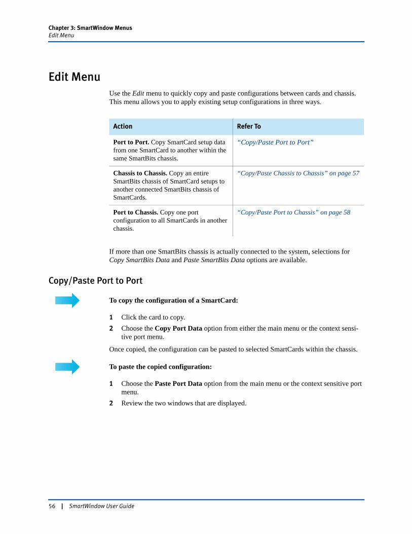
Chapter 3: SmartWindow MenusEdit Menu
Edit MenuUse the Edit menu to quickly copy and paste configurations between cards and chassis. This menu allows you to apply existing setup configurations in three ways.
If more than one SmartBits chassis is actually connected to the system, selections for Copy SmartBits Data and Paste SmartBits Data options are available.
Copy/Paste Port to Port
To copy the configuration of a SmartCard:
1 Click the card to copy.2 Choose the Copy Port Data option from either the main menu or the context sensi-
tive port menu.
Once copied, the configuration can be pasted to selected SmartCards within the chassis.
To paste the copied configuration:
1 Choose the Paste Port Data option from the main menu or the context sensitive port menu.
2 Review the two windows that are displayed.
Action Refer To
Port to Port. Copy SmartCard setup data from one SmartCard to another within the same SmartBits chassis.
“Copy/Paste Port to Port”
Chassis to Chassis. Copy an entire SmartBits chassis of SmartCard setups to another connected SmartBits chassis of SmartCards.
“Copy/Paste Chassis to Chassis” on page 57
Port to Chassis. Copy one port configuration to all SmartCards in another chassis.
“Copy/Paste Port to Chassis” on page 58
56 | SmartWindow User Guide
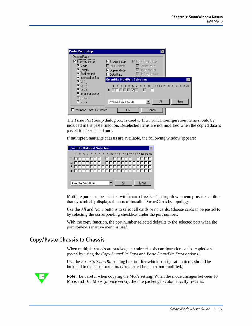
Chapter 3: SmartWindow MenusEdit Menu
The Paste Port Setup dialog box is used to filter which configuration items should be included in the paste function. Deselected items are not modified when the copied data is pasted to the selected port.
If multiple SmartBits chassis are available, the following window appears:
Multiple ports can be selected within one chassis. The drop-down menu provides a filter that dynamically displays the sets of installed SmartCards by topology.
Use the All and None buttons to select all cards or no cards. Choose cards to be pasted to by selecting the corresponding checkbox under the port number.
With the copy function, the port number selected defaults to the selected port when the port context sensitive menu is used.
Copy/Paste Chassis to Chassis
When multiple chassis are stacked, an entire chassis configuration can be copied and pasted by using the Copy SmartBits Data and Paste SmartBits Data options.
Use the Paste to SmartBits dialog box to filter which configuration items should be included in the paste function. (Unselected items are not modified.)
Note: Be careful when copying the Mode setting. When the mode changes between 10 Mbps and 100 Mbps (or vice versa), the interpacket gap automatically rescales.
SmartWindow User Guide | 57
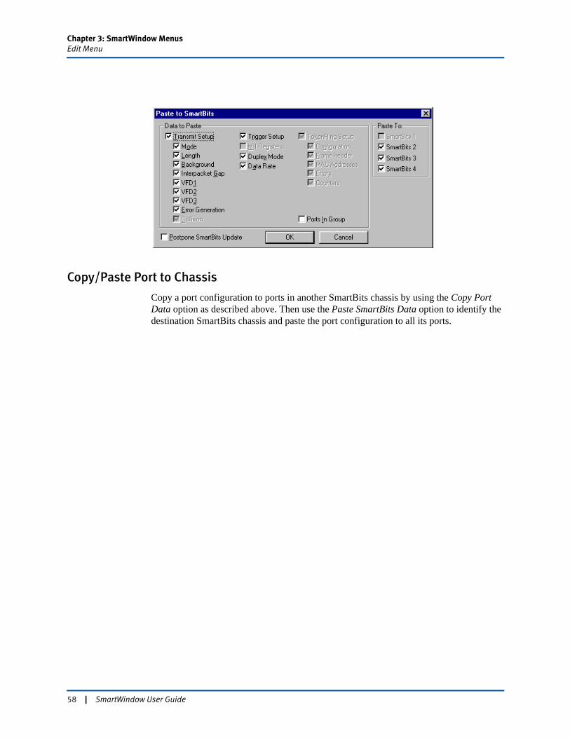
Chapter 3: SmartWindow MenusEdit Menu
Copy/Paste Port to Chassis
Copy a port configuration to ports in another SmartBits chassis by using the Copy Port Data option as described above. Then use the Paste SmartBits Data option to identify the destination SmartBits chassis and paste the port configuration to all its ports.
58 | SmartWindow User Guide
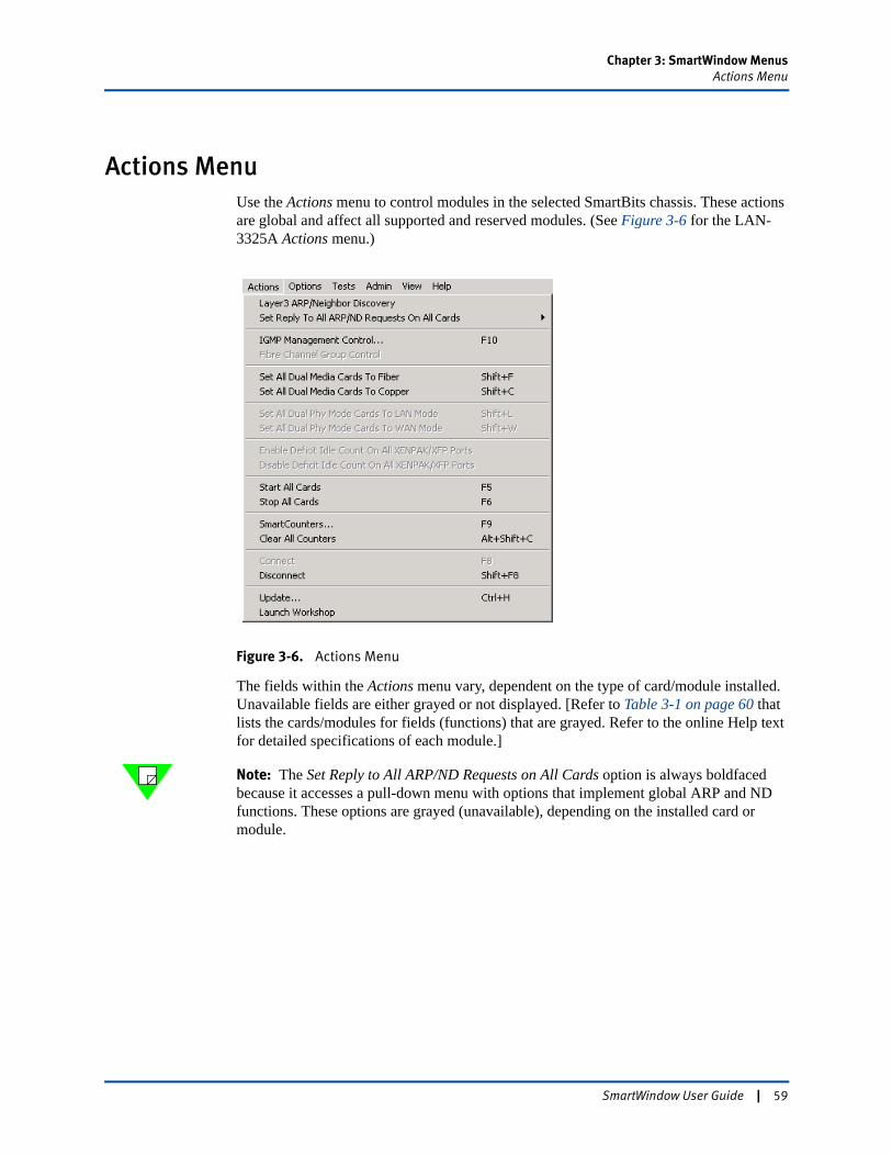
Chapter 3: SmartWindow MenusActions Menu
Actions MenuUse the Actions menu to control modules in the selected SmartBits chassis. These actions are global and affect all supported and reserved modules. (See Figure 3-6 for the LAN-3325A Actions menu.)
Figure 3-6. Actions Menu
The fields within the Actions menu vary, dependent on the type of card/module installed. Unavailable fields are either grayed or not displayed. [Refer to Table 3-1 on page 60 that lists the cards/modules for fields (functions) that are grayed. Refer to the online Help text for detailed specifications of each module.]
Note: The Set Reply to All ARP/ND Requests on All Cards option is always boldfaced because it accesses a pull-down menu with options that implement global ARP and ND functions. These options are grayed (unavailable), depending on the installed card or module.
SmartWindow User Guide | 59
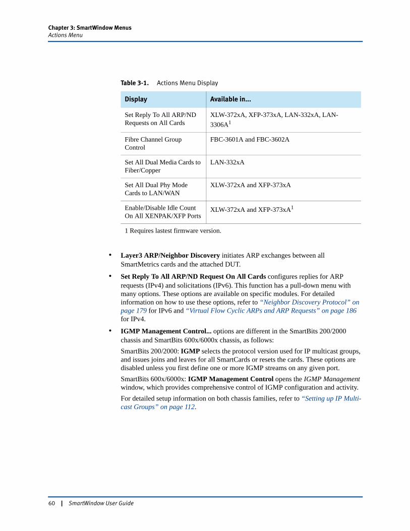
Chapter 3: SmartWindow MenusActions Menu
• Layer3 ARP/Neighbor Discovery initiates ARP exchanges between all SmartMetrics cards and the attached DUT.
• Set Reply To All ARP/ND Request On All Cards configures replies for ARP requests (IPv4) and solicitations (IPv6). This function has a pull-down menu with many options. These options are available on specific modules. For detailed information on how to use these options, refer to “Neighbor Discovery Protocol” on page 179 for IPv6 and “Virtual Flow Cyclic ARPs and ARP Requests” on page 186 for IPv4.
• IGMP Management Control... options are different in the SmartBits 200/2000 chassis and SmartBits 600x/6000x chassis, as follows:SmartBits 200/2000: IGMP selects the protocol version used for IP multicast groups, and issues joins and leaves for all SmartCards or resets the cards. These options are disabled unless you first define one or more IGMP streams on any given port.SmartBits 600x/6000x: IGMP Management Control opens the IGMP Management window, which provides comprehensive control of IGMP configuration and activity.For detailed setup information on both chassis families, refer to “Setting up IP Multi-cast Groups” on page 112.
Table 3-1. Actions Menu Display
Display Available in...
Set Reply To All ARP/ND Requests on All Cards
XLW-372xA, XFP-373xA, LAN-332xA, LAN-3306A1
Fibre Channel Group Control
FBC-3601A and FBC-3602A
Set All Dual Media Cards to Fiber/Copper
LAN-332xA
Set All Dual Phy Mode Cards to LAN/WAN
XLW-372xA and XFP-373xA
Enable/Disable Idle Count On All XENPAK/XFP Ports
XLW-372xA and XFP-373xA1
1 Requires lastest firmware version.
60 | SmartWindow User Guide

Chapter 3: SmartWindow MenusActions Menu
• Fibre Channel Group Control is enabled when SmartWindow is used to test with the FBC-3601A or FBC-3602A Fibre Channel modules. SmartWindow must be connected to the SmartBits chassis for these options to be active. These options enable you send commands to multiple fibre channel ports at the same time. (See “Send Commands to Make “Ready to Test”” on page 656 for more information.)
• Set All Dual Phy Mode Cards To LAN Mode (SmartBits 600B, SmartBits 6000B and SmartBits 6000C chassis)Set All Dual Phy Mode Cards To WAN ModeSmartWindow must be connected to the SmartBits chassis for these options to be active, and one or more XLW-372xA or XFP-373xA modules must be installed. These options enable you to the set the ports on the XLW-372xA and XFP-373xA modules to the LAN or WAN mode.
• Set All Dual Media Cards to Fiber (SmartBits 600B and 6000C chassis)Set All Dual Media Cards to CopperSmartWindow must be connected to the SmartBits chassis for these options to be active, and one or more LAN-332xA-series Dual Media modules must be installed. The options enable you to set the interface mode for all ports on all Dual Media mod-ules to either the fiber mode or copper mode. The interface mode for ports can be set individually by using the port menu.
• Enable Deficit Idle Count On All XENPAK/XFP Ports (SmartBits 6000B and SmartBits 6000C chassis)Disable Deficit Idle Count On All XENPAK/XFP PortsSmartWindow must be connected to the SmartBits chassis for these options to be active, and one or more XLW-372xA or XFP-373xA modules must be installed. The options control the use of the deficit idle count function located on the Port Setup.. window. (See “General Tab” on page 328.)
• Start All Cards (F5) starts all cards transmitting in all chassis.
• Stop All Cards (F6) stops all cards in all chassis.
• SmartCounters (F9) opens the Results Framework window. This display ccurs with the SmartBits 600x/6000x chassis. A different Smart Counter display appears with the SmartBits 200 and SmartBits 2000 chassis.
• Clear All Counters clears all counters on all cards in all chassis.
• Connect connects SmartWindow to a SmartBits chassis.
• Disconnect disconnects SmartWindow from the SmartBits chassis.
• Update… updates all card(s) with changes made in SmartWindow.
• Launch Workshop opens the SmartCounters Workshop window (SmartBits 600x/6000x).
SmartWindow User Guide | 61
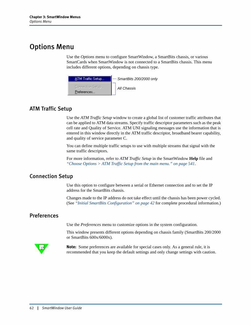
Chapter 3: SmartWindow MenusOptions Menu
Options MenuUse the Options menu to configure SmartWindow, a SmartBits chassis, or various SmartCards when SmartWindow is not connected to a SmartBits chassis. This menu includes different options, depending on chassis type.
ATM Traffic Setup
Use the ATM Traffic Setup window to create a global list of customer traffic attributes that can be applied to ATM data streams. Specify traffic descriptor parameters such as the peak cell rate and Quality of Service. ATM UNI signaling messages use the information that is entered in this window directly in the ATM traffic descriptor, broadband bearer capability, and quality of service parameter C.
You can define multiple traffic setups to use with multiple streams that signal with the same traffic descriptors.
For more information, refer to ATM Traffic Setup in the SmartWindow Help file and “Choose Options > ATM Traffic Setup from the main menu.” on page 541.
Connection Setup
Use this option to configure between a serial or Ethernet connection and to set the IP address for the SmartBits chassis.
Changes made to the IP address do not take effect until the chassis has been power cycled. (See “Initial SmartBits Configuration” on page 42 for complete procedural information.)
Preferences
Use the Preferences menu to customize options in the system configuration.
This window presents different options depending on chassis family (SmartBits 200/2000 or SmartBits 600x/6000x).
Note: Some preferences are available for special cases only. As a general rule, it is recommended that you keep the default settings and only change settings with caution.
SmartBits 200/2000 only
All Chassis
62 | SmartWindow User Guide

Chapter 3: SmartWindow MenusOptions Menu
SmartBits 200/2000
For these chassis, the Preferences window presents the following options.
General
• Connect to SmartBits at StartupWhen selected, SmartWindow attempts to establish a connection to the SmartBits system when the SmartWindow session begins. When not selected, the connection is not attempted until Actions > Connect is selected from the drop-down menus. (Default is Selected.)
• Initialize Ports after ConnectWhen selected, this option configures SmartWindow to update SmartCards automatically with new configurations upon connection. This single-user feature and applies only to the SmartBits 1000 and SmartBits 200.(Default is Deselected.)
• Initialize Ports after File/Open or File/NewWhen selected, SmartWindow automatically updates SmartCards with new configurations when files are opened or created. Automatic updates can occur only when the connection to the chassis is Online. When not selected, files can be opened and modified without downloading the configuration when the file opens. If this option is disabled, the GUI does not match the current configurations loaded on the target port and modules. (Default is Selected.)
• Show Splash Screen at StartupWhen selected, the SmartWindow splash screen (Figure 1-1 on page 18), containing essential version information, appears when the application launches. (Default is Selected.)
SmartWindow User Guide | 63
Chapter 3: SmartWindow MenusOptions Menu
• Use Left-Click popup menu over SmartCardsThis option from a previous SmartWindow version remains available for users who prefer it. (Current default is to right-click a SmartCard to access its menu.)
SmartMetrics Ethernet Cards (ML-77xx)
• Allow time control of ARP requestsSome systems cannot handle ARP requests sent at full wire speed rate. If ARPs are missed by the DUT(s), then Layer 3 tests fail. To overcome this problem, select Allow time control of ARP requests, then set the gap between ARP requests to a suitable testing rate.
• Default GatewayUse this field to define a default gateway for Layer 3 tests when required.
• Default Netmask.Use this field to define a default netmask when required.
• Default to SmartMetrics mode After File/NewSmartMetrics mode is normally disabled. This option sets modules into the SmartMetrics mode when a new configuration file is opened. (Default is Deselected.)
Fast Ethernet/Gigabit Cards
These options apply to cards that have an MII interface and are capable of autonegotiating line speed and duplex mode.
• Allow MII/GMII Auto-NegotiateWhen selected, this option allows cards with an MII or GMII interface to autonegotiate line speeds and duplex mode. When not selected, set these parameters by using SmartWindow. (Default is Selected.)
When this option is selected, autonegotiation is enabled globally for the card ports; the AN enabled bits are set in the port control registers. These settings always over-ride the control register values saved in a *.prf configuration file. As a result, if the global MII/GMII register bit settings are modified, the configuration file is saved, and the chassis is disconnected, the global settings take precedence over your file settings the next time that you connect to the chassis and load the configuration file.
Note: It is highly recommended to force the line speed to the desired rate for testing purposes. When the transceivers autonegotiate, your MII configurations are downloaded.
• Restore MII Control Register 0 after File/OpenWhen selected, MII register 0 (control) is updated when a new configuration file is opened. When not selected, the update occurs only when warranted by a configuration change. (Default is Deselected. See “MII Registers” on page 163 for more information.)
SX-6x05 10Mb Ethernet
• Allow bit level control of VFD1 & VFD2For 10Mbps Ethernet 6x05 SmartCards only. When selected, you can define the
64 | SmartWindow User Guide
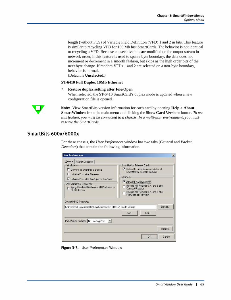
Chapter 3: SmartWindow MenusOptions Menu
length (without FCS) of Variable Field Definition (VFD) 1 and 2 in bits. This feature is similar to recycling VFD for 100 Mb fast SmartCards. The behavior is not identical to recycling a VFD. Because consecutive bits are modified on the output stream in network order, if this feature is used to span a byte boundary, the data does not increment or decrement in a smooth fashion, but skips as the high order bits of the next byte change. If random VFDs 1 and 2 are selected on a non-byte boundary, behavior is normal. (Default is Unselected.)
ST-6410 Full Duplex 10Mb Ethernet
• Restore duplex setting after File/OpenWhen selected, the ST-6410 SmartCard’s duplex mode is updated when a new configuration file is opened.
Note: View SmartBits version information for each card by opening Help > About SmartWindow from the main menu and clicking the Show Card Versions button. To use this feature, you must be connected to a chassis. In a multi-user environment, you must reserve the SmartCards.
SmartBits 600x/6000x
For these chassis, the User Preferences window has two tabs (General and Packet Decoders) that contain the following information.
Figure 3-7. User Preferences Window
SmartWindow User Guide | 65
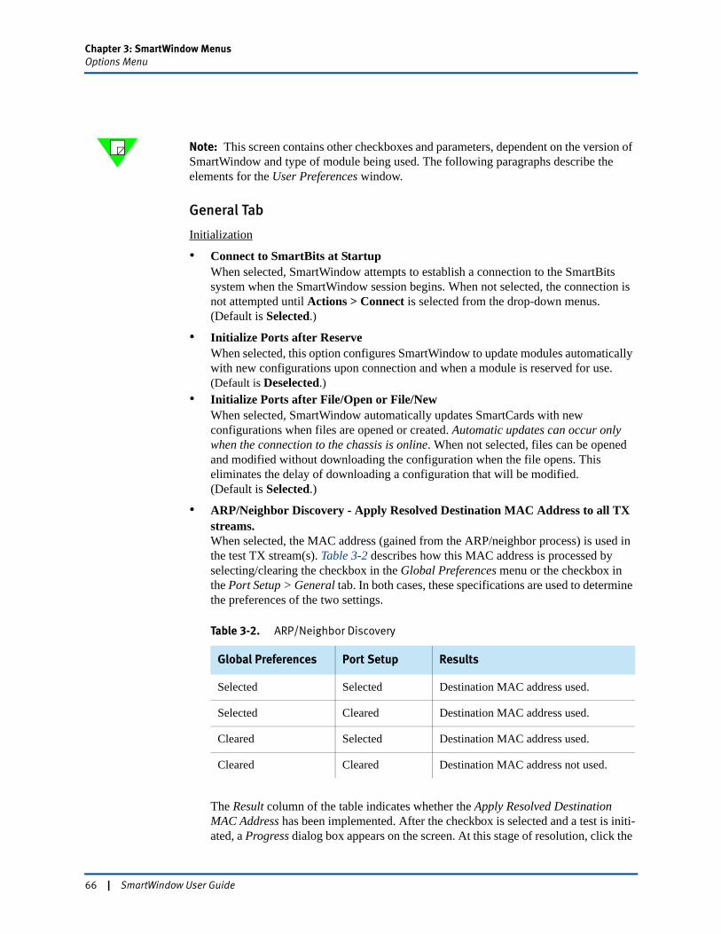
Chapter 3: SmartWindow MenusOptions Menu
Note: This screen contains other checkboxes and parameters, dependent on the version of SmartWindow and type of module being used. The following paragraphs describe the elements for the User Preferences window.
General Tab
Initialization
• Connect to SmartBits at StartupWhen selected, SmartWindow attempts to establish a connection to the SmartBits system when the SmartWindow session begins. When not selected, the connection is not attempted until Actions > Connect is selected from the drop-down menus. (Default is Selected.)
• Initialize Ports after ReserveWhen selected, this option configures SmartWindow to update modules automatically with new configurations upon connection and when a module is reserved for use.(Default is Deselected.)
• Initialize Ports after File/Open or File/NewWhen selected, SmartWindow automatically updates SmartCards with new configurations when files are opened or created. Automatic updates can occur only when the connection to the chassis is online. When not selected, files can be opened and modified without downloading the configuration when the file opens. This eliminates the delay of downloading a configuration that will be modified. (Default is Selected.)
• ARP/Neighbor Discovery - Apply Resolved Destination MAC Address to all TX streams.When selected, the MAC address (gained from the ARP/neighbor process) is used in the test TX stream(s). Table 3-2 describes how this MAC address is processed by selecting/clearing the checkbox in the Global Preferences menu or the checkbox in the Port Setup > General tab. In both cases, these specifications are used to determine the preferences of the two settings.
The Result column of the table indicates whether the Apply Resolved Destination MAC Address has been implemented. After the checkbox is selected and a test is initi-ated, a Progress dialog box appears on the screen. At this stage of resolution, click the
Table 3-2. ARP/Neighbor Discovery
Global Preferences Port Setup Results
Selected Selected Destination MAC address used.
Selected Cleared Destination MAC address used.
Cleared Selected Destination MAC address used.
Cleared Cleared Destination MAC address not used.
66 | SmartWindow User Guide
Chapter 3: SmartWindow MenusOptions Menu
Abort button to stop the process. However, any actions (resolutions of MAC addresses/sending ARPs) implemented up to this point cannot be recalled.
• Default to SmartMetrics mode After File/NewSmartMetrics mode is normally disabled. This option sets modules into the SmartMetrics mode when a new configuration file is opened. (Default is Deselected.)
MII Cards
These options apply to modules that have an MII interface and are capable of autonegotiating line speed and duplex mode.
• Allow MII Auto-NegotiationWhen selected, this option allows Ethernet modules with MII interfaces to autonegotiate line speed and duplex mode. When not selected, set these parameters by using SmartWindow. (Default is Selected.)
When this option is selected, autonegotiation is enabled globally for the card ports; the AN enabled bits are set in the port control registers. These settings always over-ride the control register values saved in a *.prf configuration file. As a result, if the global MII register bit settings are modified, the configuration file is saved, and the chassis is disconnected, the global settings take precedence over your file settings the next time that you connect to the chassis and load the configuration file. (See “MII Registers” on page 163 for more information.)
Note: It is highly recommended to force the line speed to the desired rate for testing purposes. When the transceivers autonegotiate, it can produce unexpected test results because the line speed is not what was expected.
• Restore MII Register 0, 4, and 9 after File/Open or File/NewWhen selected, MII registers 0, 4, and 9 are updated when a new configuration file is opened. When not selected, the update occurs only when warranted by a configuration change. (Default is not selected.)
• Restore MII Register 0, 4, and 9 after Connect/ReserveWhen selected, registers 0, 4, and 9 are updated when SmartWindow connects to the chassis and when a module is reserved for use.
Default MDIO Template
This pane identifies the default template MDIO file for the port, when it is equipped with a XAUI extender card with MDIO interface.
SmartWindow provides six predefined files. You can quickly select any of these from the default directory by clicking the Browse button. The files are:
• ieee802_3ae45.mido – Based on IEEE Std.802.3ae, with the first five devices defined. It includes no vendor specifics and no extensions.
SmartWindow User Guide | 67
Chapter 3: SmartWindow MenusOptions Menu
• BitBlitz802_3ae45.mdio – BitBlitz IEEE Std.802.3ae. It includes the vendor’s specifics and extensions.
• jdsu802_3ae45.mdio – JDSU IEEE Std.802.3ae. It includes the vendor’s specifics and extensions.
• agilent802_3ae45.mdio – Agilent IEEE Std.802.3ae. It includes the vendor’s specifics and extensions.
• intel802_3ae45.mdio – Intel’s IEEE Std.802.3ae. It includes the vendor’s specifics and extensions.
Click the Browse button to locate a custom MDIO template file in a different directory on your PC. Click the New or Edit button to create a new template file or modify the specified default file, respectively. (The MDIO Template Editor opens. Use it to set new values for devices and registers.)
IPv6 Display Formats
Use these options to select how IPv6 addresses are shown in dialog boxes and windows for modules that support IPv6 streams. RFC 2373 provides a detailed explanation of these formats. It is paraphrased here:
Hexadecimal The preferred form is x:x:x:x:x:x:x:x, where the 'x's are the hexadecimal values of the eight 16-bit pieces of the address.
Examples FEDC:BA98:7654:3210:FEDC:BA98:7654:3210
1080:0:0:0:8:800:200C:417A
No leading zero This format is like the Preferred format above, but the leading zeros in individual fields are omitted. (There must be at least one numeral in every field.)
Compact Some methods of allocating IPv6 addresses result in addresses that contain long strings of zero bits. To simplify writing such addresses, a special syntax is available to compress the zeros. The use of “::” indicates multiple groups of 16-bits of zeros. The “::” can only appear once in an address. The “::” can also be used to compress the leading and/or trailing zeros in an address.
Examples Unicast address:1080:0:0:0:8:800:200C:417A>1080::8:800:200C:417A
Multicast address:FF01:0:0:0:0:0:0:101> FF01::101
Loopback address:0:0:0:0:0:0:0:1> ::1
Unspecified address:0:0:0:0:0:0:0:0> ::
Mixed This form can be more convenient when dealing with a mixed environment of IPv4 and IPv6 nodes. It is x:x:x:x:x:x:d.d.d.d, where the 'x's are the hexadecimal values of the six
68 | SmartWindow User Guide
Chapter 3: SmartWindow MenusOptions Menu
high-order 16-bit pieces of the address, and the 'd's are the decimal values of the four low-order 8-bit pieces of the address (standard IPv4 representation).
Examples 0:0:0:0:0:0:13.1.68.3in compressed form:::13.1.68.3
0:0:0:0:0:FFFF:129.144.52.38in compressed form:::FFFF:129.144.52.38
Packet Decoders Tab
The fields within this tab are used to import and display the path of a data decoder. (Refer to Chapter 5, “Advanced Operational Theory,” for a description of how to capture files and use a data decoder to analyze SmartWindows data.)
SmartWindow User Guide | 69
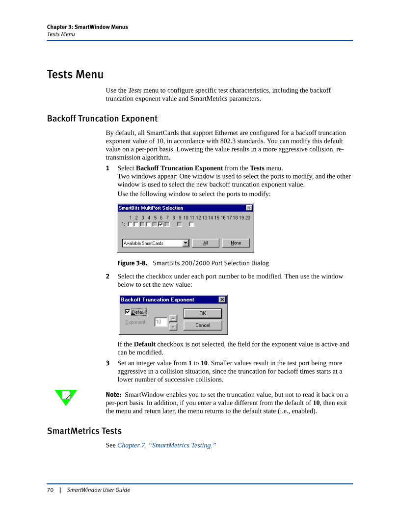
Chapter 3: SmartWindow MenusTests Menu
Tests MenuUse the Tests menu to configure specific test characteristics, including the backoff truncation exponent value and SmartMetrics parameters.
Backoff Truncation Exponent
By default, all SmartCards that support Ethernet are configured for a backoff truncation exponent value of 10, in accordance with 802.3 standards. You can modify this default value on a per-port basis. Lowering the value results in a more aggressive collision, re-transmission algorithm.1 Select Backoff Truncation Exponent from the Tests menu.
Two windows appear: One window is used to select the ports to modify, and the other window is used to select the new backoff truncation exponent value.Use the following window to select the ports to modify:
Figure 3-8. SmartBits 200/2000 Port Selection Dialog
2 Select the checkbox under each port number to be modified. Then use the window below to set the new value:
If the Default checkbox is not selected, the field for the exponent value is active and can be modified.
3 Set an integer value from 1 to 10. Smaller values result in the test port being more aggressive in a collision situation, since the truncation for backoff times starts at a lower number of successive collisions.
Note: SmartWindow enables you to set the truncation value, but not to read it back on a per-port basis. In addition, if you enter a value different from the default of 10, then exit the menu and return later, the menu returns to the default state (i.e., enabled).
SmartMetrics Tests
See Chapter 7, “SmartMetrics Testing.”
70 | SmartWindow User Guide
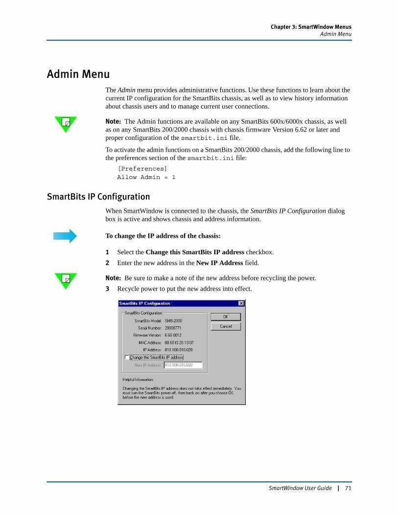
Chapter 3: SmartWindow MenusAdmin Menu
Admin MenuThe Admin menu provides administrative functions. Use these functions to learn about the current IP configuration for the SmartBits chassis, as well as to view history information about chassis users and to manage current user connections.
Note: The Admin functions are available on any SmartBits 600x/6000x chassis, as well as on any SmartBits 200/2000 chassis with chassis firmware Version 6.62 or later and proper configuration of the smartbit.ini file.
To activate the admin functions on a SmartBits 200/2000 chassis, add the following line to the preferences section of the smartbit.ini file:
[Preferences]Allow Admin = 1
SmartBits IP Configuration
When SmartWindow is connected to the chassis, the SmartBits IP Configuration dialog box is active and shows chassis and address information.
To change the IP address of the chassis:
1 Select the Change this SmartBits IP address checkbox.2 Enter the new address in the New IP Address field.
Note: Be sure to make a note of the new address before recycling the power.3 Recycle power to put the new address into effect.
SmartWindow User Guide | 71
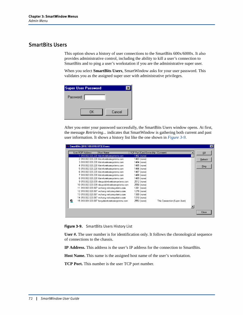
Chapter 3: SmartWindow MenusAdmin Menu
SmartBits Users
This option shows a history of user connections to the SmartBits 600x/6000x. It also provides administrative control, including the ability to kill a user’s connection to SmartBits and to ping a user’s workstation if you are the administrative super user.
When you select SmartBits Users, SmartWindow asks for your user password. This validates you as the assigned super user with administrative privileges.
After you enter your password successfully, the SmartBits Users window opens. At first, the message Retrieving... indicates that SmartWindow is gathering both current and past user information. It shows a history list like the one shown in Figure 3-9.
Figure 3-9. SmartBits Users History List
User #. The user number is for identification only. It follows the chronological sequence of connections to the chassis.
IP Address. This address is the user’s IP address for the connection to SmartBits.
Host Name. This name is the assigned host name of the user’s workstation.
TCP Port. This number is the user TCP port number.
72 | SmartWindow User Guide
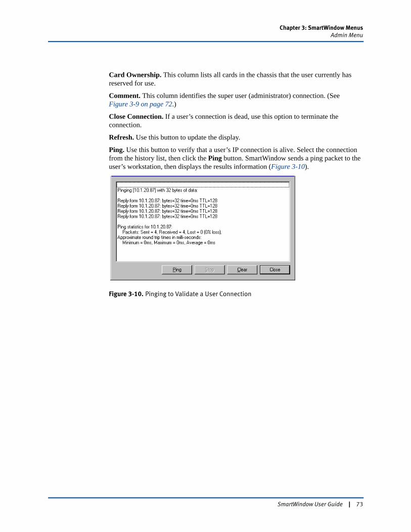
Chapter 3: SmartWindow MenusAdmin Menu
Card Ownership. This column lists all cards in the chassis that the user currently has reserved for use.
Comment. This column identifies the super user (administrator) connection. (See Figure 3-9 on page 72.)
Close Connection. If a user’s connection is dead, use this option to terminate the connection.
Refresh. Use this button to update the display.
Ping. Use this button to verify that a user’s IP connection is alive. Select the connection from the history list, then click the Ping button. SmartWindow sends a ping packet to the user’s workstation, then displays the results information (Figure 3-10).
Figure 3-10. Pinging to Validate a User Connection
SmartWindow User Guide | 73
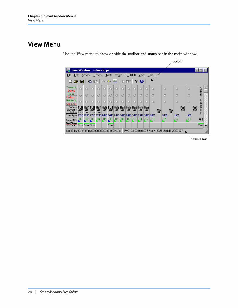
Chapter 3: SmartWindow MenusView Menu
View MenuUse the View menu to show or hide the toolbar and status bar in the main window.
Toolbar
Status bar
74 | SmartWindow User Guide
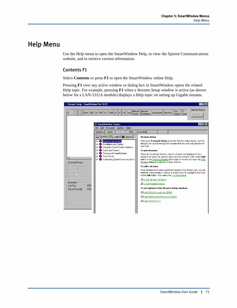
Chapter 3: SmartWindow MenusHelp Menu
Help MenuUse the Help menu to open the SmartWindow Help, to view the Spirent Communications website, and to retrieve version information.
Contents F1
Select Contents or press F1 to open the SmartWindow online Help.
Pressing F1 over any active window or dialog box in SmartWindow opens the related Help topic. For example, pressing F1 when a Streams Setup window is active (as shown below for a LAN-3311A module) displays a Help topic on setting up Gigabit streams.
SmartWindow User Guide | 75

76 | SmartWindow User Guide
Chapter 4
Basic Operational Theory
SmartWindow performs testing and analysis on a diverse set of protocols. Understanding its basic operation can help speed and optimize test setup.
In this chapter...
• SmartWindow Basics . . . . 78
• Multiple Instances of SmartWindow . . . . 81
• Naming Connections . . . . 82
• Grouping SmartCards . . . . 84
• Multi-user Operation . . . . 92
• Configuration Files . . . . 97
• Configuring SmartBits Cards . . . . 107
• Types of Tests . . . . 109
SmartWindow User Guide | 77

Chapter 4: Basic Operational TheorySmartWindow Basics
SmartWindow BasicsSmartWindow allows you to open up to five simultaneous instances of the program.
• A single instance of SmartWindow can connect to only one SmartBits chassis.
• Multiple instances can connect to separate chassis or to the same chassis (if the chassis is multi-user ready).1
Multiple instances do not share timing information, so be careful to design tests with this in mind. For example, you can set up two SmartBits chassis—one on either end of a DUT or SUT—then transmit from SmartBits 1 to SmartBits 2. Throughput and packet loss tests can be performed with this type of configuration, but latency tests would not have much value since those tests depend on precise timing information.
Single Instances of SmartWindow
Opening a single instance of SmartWindow is straightforward. Refer to “Starting SmartWindow” on page 31.
Each time you connect to a new chassis, SmartWindow remembers the IP address and includes it on the list. The next time you choose Options > Connection Setup, the IP addresses of all recent connections appear in the drop-down menu for Remote SmartBits (SmartBits 600x/6000x) or Remote Host (SmartBits 200/2000).
As long as these chassis are active on the network and path authorization is granted, you can select a new connection from the drop-down menu.
1. See “Multi-user Operation” on page 92.
78 | SmartWindow User Guide
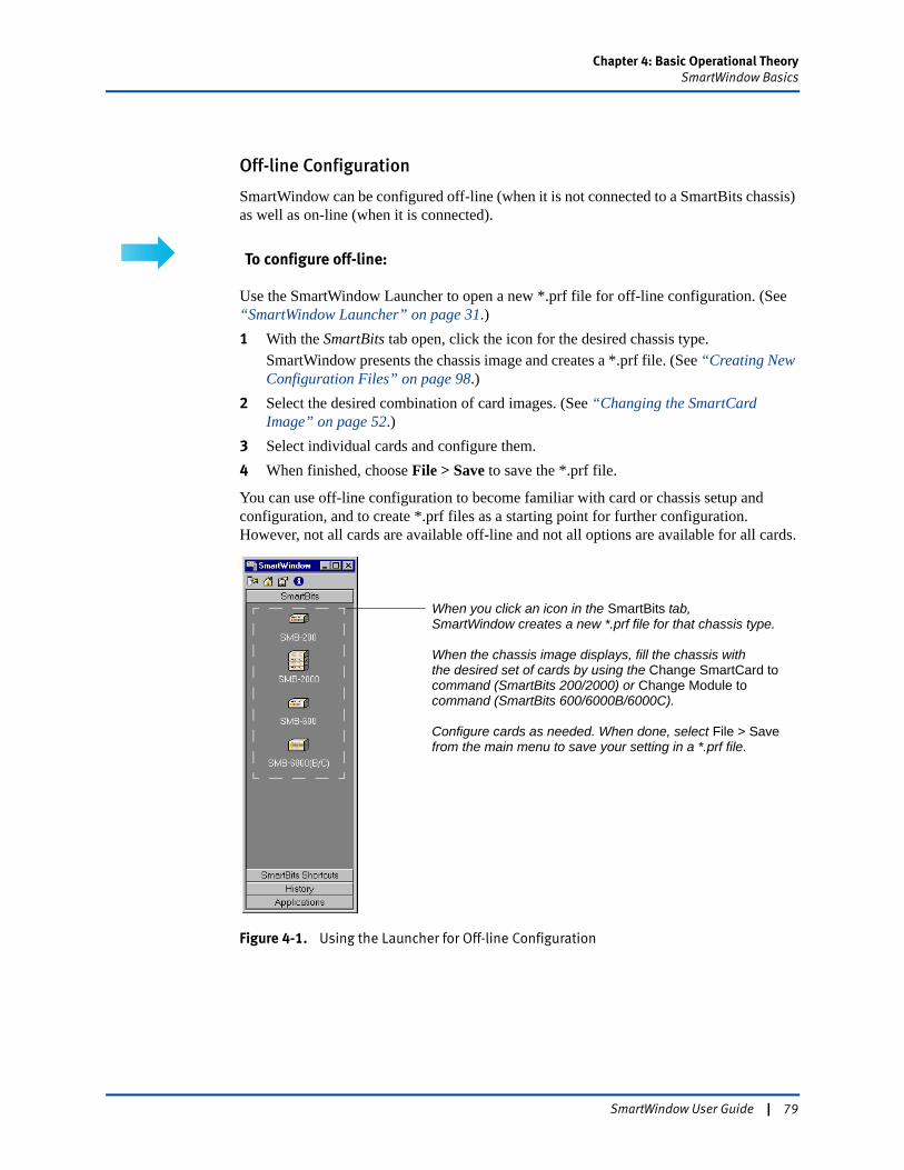
Chapter 4: Basic Operational TheorySmartWindow Basics
Off-line Configuration
SmartWindow can be configured off-line (when it is not connected to a SmartBits chassis) as well as on-line (when it is connected).
To configure off-line:
Use the SmartWindow Launcher to open a new *.prf file for off-line configuration. (See “SmartWindow Launcher” on page 31.) 1 With the SmartBits tab open, click the icon for the desired chassis type.
SmartWindow presents the chassis image and creates a *.prf file. (See “Creating New Configuration Files” on page 98.)
2 Select the desired combination of card images. (See “Changing the SmartCard Image” on page 52.)
3 Select individual cards and configure them.4 When finished, choose File > Save to save the *.prf file.
You can use off-line configuration to become familiar with card or chassis setup and configuration, and to create *.prf files as a starting point for further configuration. However, not all cards are available off-line and not all options are available for all cards.
Figure 4-1. Using the Launcher for Off-line Configuration
When you click an icon in the SmartBits tab,SmartWindow creates a new *.prf file for that chassis type.
When the chassis image displays, fill the chassis withthe desired set of cards by using the Change SmartCard tocommand (SmartBits 200/2000) or Change Module tocommand (SmartBits 600/6000B/6000C).
Configure cards as needed. When done, select File > Savefrom the main menu to save your setting in a *.prf file.
SmartWindow User Guide | 79
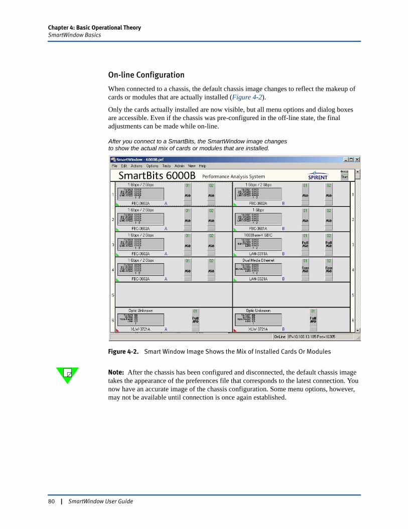
Chapter 4: Basic Operational TheorySmartWindow Basics
On-line Configuration
When connected to a chassis, the default chassis image changes to reflect the makeup of cards or modules that are actually installed (Figure 4-2).
Only the cards actually installed are now visible, but all menu options and dialog boxes are accessible. Even if the chassis was pre-configured in the off-line state, the final adjustments can be made while on-line.
Figure 4-2. Smart Window Image Shows the Mix of Installed Cards Or Modules
Note: After the chassis has been configured and disconnected, the default chassis image takes the appearance of the preferences file that corresponds to the latest connection. You now have an accurate image of the chassis configuration. Some menu options, however, may not be available until connection is once again established.
After you connect to a SmartBits, the SmartWindow image changesto show the actual mix of cards or modules that are installed.
80 | SmartWindow User Guide
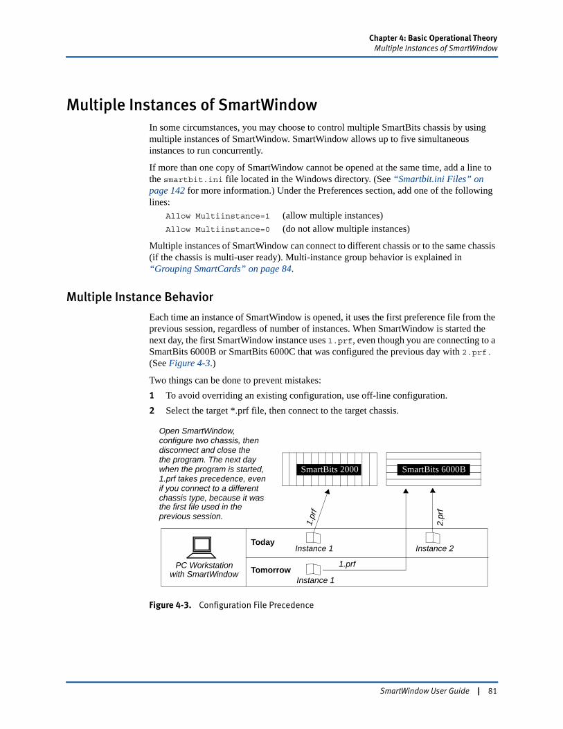
Chapter 4: Basic Operational TheoryMultiple Instances of SmartWindow
Multiple Instances of SmartWindowIn some circumstances, you may choose to control multiple SmartBits chassis by using multiple instances of SmartWindow. SmartWindow allows up to five simultaneous instances to run concurrently.
If more than one copy of SmartWindow cannot be opened at the same time, add a line to the smartbit.ini file located in the Windows directory. (See “Smartbit.ini Files” on page 142 for more information.) Under the Preferences section, add one of the following lines:
Allow Multiinstance=1 (allow multiple instances)Allow Multiinstance=0 (do not allow multiple instances)
Multiple instances of SmartWindow can connect to different chassis or to the same chassis (if the chassis is multi-user ready). Multi-instance group behavior is explained in “Grouping SmartCards” on page 84.
Multiple Instance Behavior
Each time an instance of SmartWindow is opened, it uses the first preference file from the previous session, regardless of number of instances. When SmartWindow is started the next day, the first SmartWindow instance uses 1.prf, even though you are connecting to a SmartBits 6000B or SmartBits 6000C that was configured the previous day with 2.prf. (See Figure 4-3.)
Two things can be done to prevent mistakes:1 To avoid overriding an existing configuration, use off-line configuration.2 Select the target *.prf file, then connect to the target chassis.
Figure 4-3. Configuration File Precedence
SmartBits 2000
Today
Tomorrow
Instance 1
Instance 1
Instance 2
Open SmartWindow,configure two chassis, thendisconnect and close thethe program. The next daywhen the program is started,1.prf takes precedence, even
1.pr
f
2.pr
f
PC Workstationwith SmartWindow
the first file used in theprevious session.
SmartBits 6000B
if you connect to a differentchassis type, because it was
1.prf
SmartWindow User Guide | 81
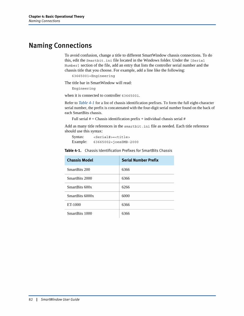
Chapter 4: Basic Operational TheoryNaming Connections
Naming ConnectionsTo avoid confusion, change a title to different SmartWindow chassis connections. To do this, edit the Smartbit.ini file located in the Windows folder. Under the [Serial Number] section of the file, add an entry that lists the controller serial number and the chassis title that you choose. For example, add a line like the following:
63665001=Engineering
The title bar in SmartWindow will read:Engineering
when it is connected to controller 63665001.
Refer to Table 4-1 for a list of chassis identification prefixes. To form the full eight-character serial number, the prefix is concatenated with the four-digit serial number found on the back of each SmartBits chassis.
Full serial # = Chassis identification prefix + individual chassis serial #
Add as many title references in the smartbit.ini file as needed. Each title reference should use this syntax:
Syntax: <Serial#>=<title>
Example: 63665002=joesSMB-2000
Table 4-1. Chassis Identification Prefixes for SmartBits Chassis
Chassis Model Serial Number Prefix
SmartBits 200 6366
SmartBits 2000 6366
SmartBits 600x 6266
SmartBits 6000x 6000
ET-1000 6366
SmartBits 1000 6366
82 | SmartWindow User Guide
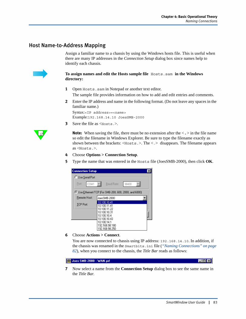
Chapter 4: Basic Operational TheoryNaming Connections
Host Name-to-Address MappingAssign a familiar name to a chassis by using the Windows hosts file. This is useful when there are many IP addresses in the Connection Setup dialog box since names help to identify each chassis.
To assign names and edit the Hosts sample file Hosts.sam in the Windows directory:
1 Open Hosts.sam in Notepad or another text editor.The sample file provides information on how to add and edit entries and comments.
2 Enter the IP address and name in the following format. (Do not leave any spaces in the familiar name.)Syntax:<IP address>=<name>Example:192.168.14.10 JoesSMB-2000
3 Save the file as <Hosts.>.
Note: When saving the file, there must be no extension after the < . > in the file name so edit the filename in Windows Explorer. Be sure to type the filename exactly as shown between the brackets: <Hosts.>. The <.> disappears. The filename appears as <Hosts.>.
4 Choose Options > Connection Setup.5 Type the name that was entered in the Hosts file (JoesSMB-2000), then click OK.
6 Choose Actions > Connect.You are now connected to chassis using IP address: 192.168.14.10. In addition, if the chassis was renamed in the Smartbits.ini file (“Naming Connections” on page 82), when you connect to the chassis, the Title Bar reads as follows:
7 Now select a name from the Connection Setup dialog box to see the same name in the Title Bar.
SmartWindow User Guide | 83
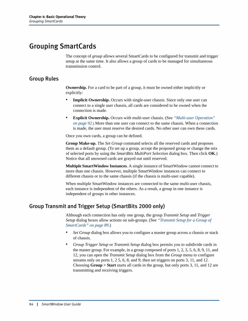
Chapter 4: Basic Operational TheoryGrouping SmartCards
Grouping SmartCardsThe concept of group allows several SmartCards to be configured for transmit and trigger setup at the same time. It also allows a group of cards to be managed for simultaneous transmission control.
Group Rules
Ownership. For a card to be part of a group, it must be owned either implicitly or explicitly:
• Implicit Ownership. Occurs with single-user chassis. Since only one user can connect to a single user chassis, all cards are considered to be owned when the connection is made.
• Explicit Ownership. Occurs with multi-user chassis. (See “Multi-user Operation” on page 92.) More than one user can connect to the same chassis. When a connection is made, the user must reserve the desired cards. No other user can own these cards.
Once you own cards, a group can be defined.
Group Make-up. The Set Group command selects all the reserved cards and proposes them as a default group. (To set up a group, accept the proposed group or change the mix of selected ports by using the SmartBits MultiPort Selection dialog box. Then click OK.) Notice that all unowned cards are grayed out until reserved.
Multiple SmartWindow Instances. A single instance of SmartWindow cannot connect to more than one chassis. However, multiple SmartWindow instances can connect to different chassis or to the same chassis (if the chassis is multi-user capable).
When multiple SmartWindow instances are connected to the same multi-user chassis, each instance is independent of the others. As a result, a group in one instance is independent of groups in other instances.
Group Transmit and Trigger Setup (SmartBits 2000 only)
Although each connection has only one group, the group Transmit Setup and Trigger Setup dialog boxes allow actions on sub-groups. (See “Transmit Setup for a Group of SmartCards” on page 89.)
• Set Group dialog box allows you to configure a master group across a chassis or stack of chassis.
• Group Trigger Setup or Transmit Setup dialog box permits you to subdivide cards in the master group. For example, in a group composed of ports 1, 2, 3, 5, 6, 8, 9, 11, and 12, you can open the Transmit Setup dialog box from the Group menu to configure streams only on ports 1, 2 5, 6, 8, and 9; then set triggers on ports 3, 11, and 12. Choosing Group > Start starts all cards in the group, but only ports 3, 11, and 12 are transmitting and receiving triggers.
84 | SmartWindow User Guide
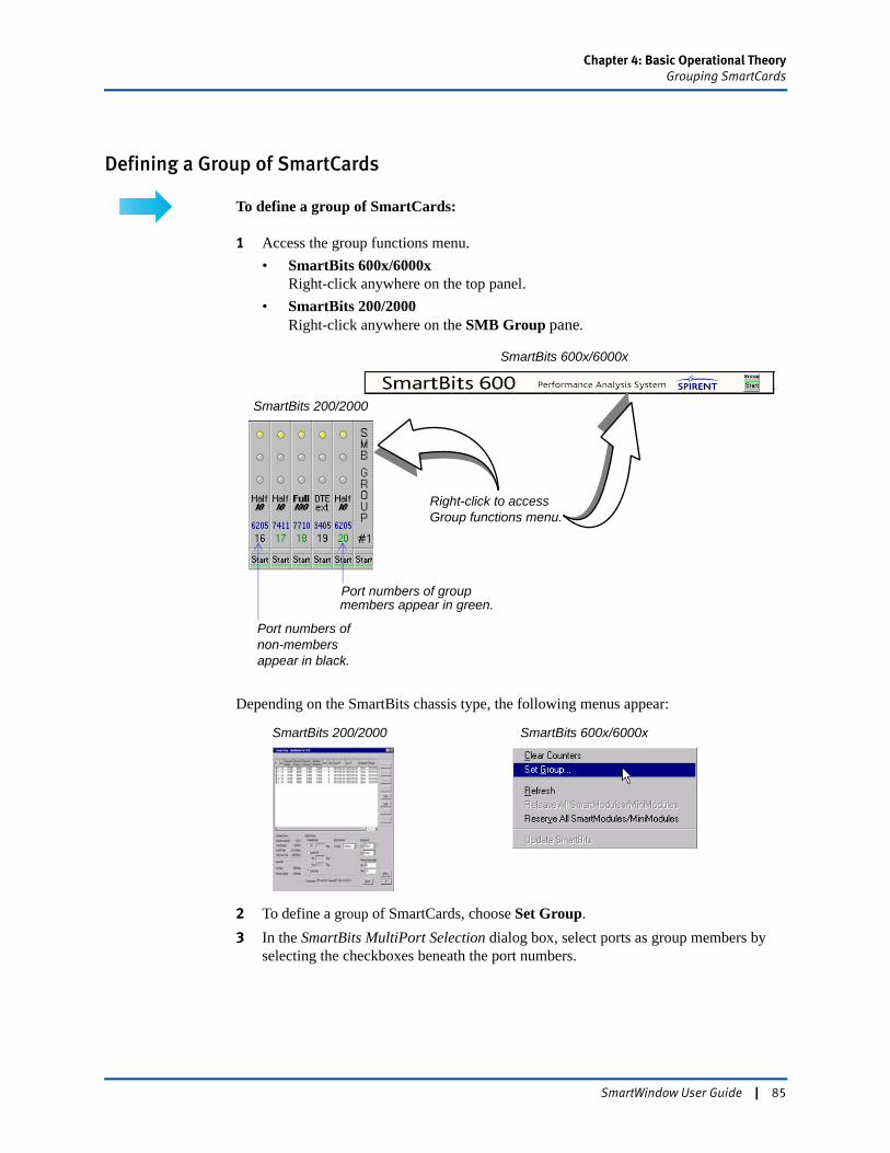
Chapter 4: Basic Operational TheoryGrouping SmartCards
Defining a Group of SmartCards
To define a group of SmartCards:
1 Access the group functions menu.• SmartBits 600x/6000x
Right-click anywhere on the top panel.• SmartBits 200/2000
Right-click anywhere on the SMB Group pane.
Depending on the SmartBits chassis type, the following menus appear:
2 To define a group of SmartCards, choose Set Group.3 In the SmartBits MultiPort Selection dialog box, select ports as group members by
selecting the checkboxes beneath the port numbers.
Right-click to access Group functions menu.
SmartBits 200/2000
SmartBits 600x/6000x
Port numbers of groupmembers appear in green.
Port numbers of non-members appear in black.
SmartBits 200/2000 SmartBits 600x/6000x
SmartWindow User Guide | 85
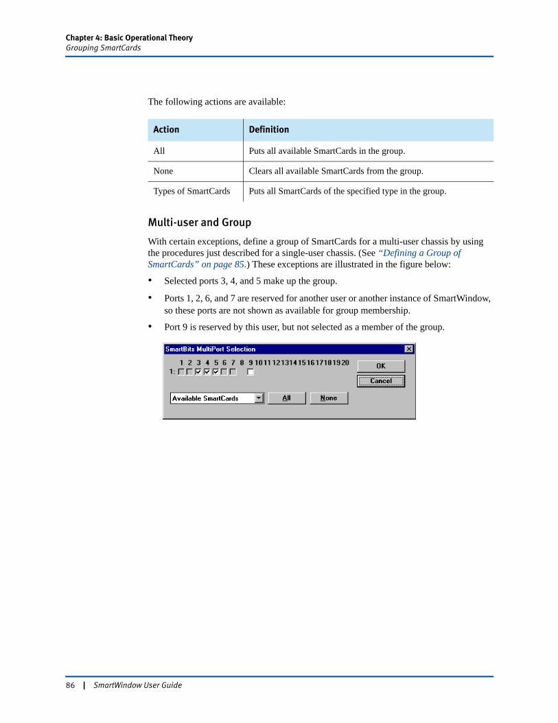
Chapter 4: Basic Operational TheoryGrouping SmartCards
The following actions are available:
Multi-user and Group
With certain exceptions, define a group of SmartCards for a multi-user chassis by using the procedures just described for a single-user chassis. (See “Defining a Group of SmartCards” on page 85.) These exceptions are illustrated in the figure below:
• Selected ports 3, 4, and 5 make up the group.
• Ports 1, 2, 6, and 7 are reserved for another user or another instance of SmartWindow, so these ports are not shown as available for group membership.
• Port 9 is reserved by this user, but not selected as a member of the group.
Action Definition
All Puts all available SmartCards in the group.
None Clears all available SmartCards from the group.
Types of SmartCards Puts all SmartCards of the specified type in the group.
86 | SmartWindow User Guide
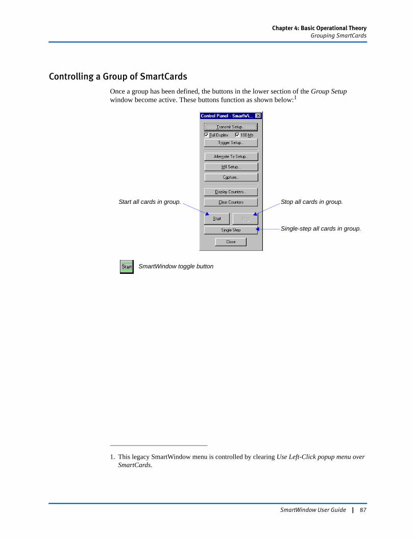
Chapter 4: Basic Operational TheoryGrouping SmartCards
Controlling a Group of SmartCards
Once a group has been defined, the buttons in the lower section of the Group Setup window become active. These buttons function as shown below:1
1. This legacy SmartWindow menu is controlled by clearing Use Left-Click popup menu over SmartCards.
Start all cards in group.
Single-step all cards in group.
Stop all cards in group.
SmartWindow toggle button
SmartWindow User Guide | 87
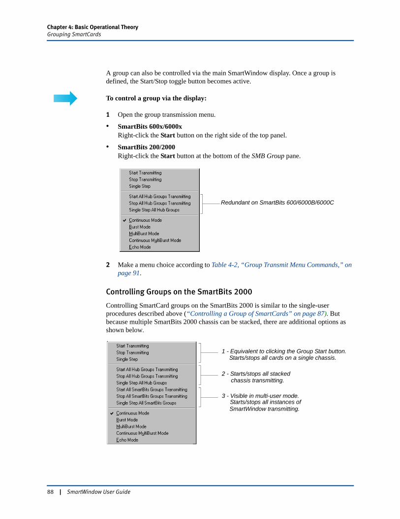
Chapter 4: Basic Operational TheoryGrouping SmartCards
A group can also be controlled via the main SmartWindow display. Once a group is defined, the Start/Stop toggle button becomes active.
To control a group via the display:
1 Open the group transmission menu.
• SmartBits 600x/6000xRight-click the Start button on the right side of the top panel.
• SmartBits 200/2000Right-click the Start button at the bottom of the SMB Group pane.
2 Make a menu choice according to Table 4-2, “Group Transmit Menu Commands,” on page 91.
Controlling Groups on the SmartBits 2000
Controlling SmartCard groups on the SmartBits 2000 is similar to the single-user procedures described above (“Controlling a Group of SmartCards” on page 87). But because multiple SmartBits 2000 chassis can be stacked, there are additional options as shown below.
Redundant on SmartBits 600/6000B/6000C
3 - Visible in multi-user mode.
1 - Equivalent to clicking the Group Start button.
2 - Starts/stops all stacked
Starts/stops all instances of SmartWindow transmitting.
chassis transmitting.
Starts/stops all cards on a single chassis.
88 | SmartWindow User Guide
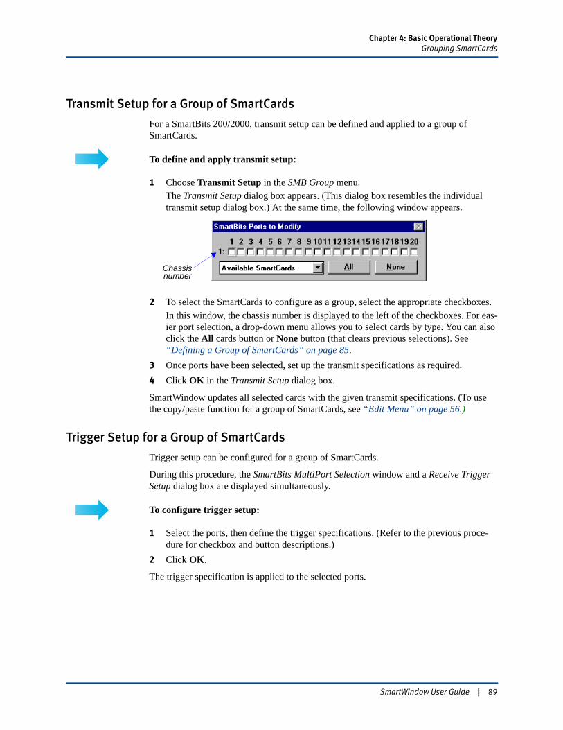
Chapter 4: Basic Operational TheoryGrouping SmartCards
Transmit Setup for a Group of SmartCards
For a SmartBits 200/2000, transmit setup can be defined and applied to a group of SmartCards.
To define and apply transmit setup:
1 Choose Transmit Setup in the SMB Group menu.The Transmit Setup dialog box appears. (This dialog box resembles the individual transmit setup dialog box.) At the same time, the following window appears.
2 To select the SmartCards to configure as a group, select the appropriate checkboxes.In this window, the chassis number is displayed to the left of the checkboxes. For eas-ier port selection, a drop-down menu allows you to select cards by type. You can also click the All cards button or None button (that clears previous selections). See “Defining a Group of SmartCards” on page 85.
3 Once ports have been selected, set up the transmit specifications as required.4 Click OK in the Transmit Setup dialog box.
SmartWindow updates all selected cards with the given transmit specifications. (To use the copy/paste function for a group of SmartCards, see “Edit Menu” on page 56.)
Trigger Setup for a Group of SmartCards
Trigger setup can be configured for a group of SmartCards.
During this procedure, the SmartBits MultiPort Selection window and a Receive Trigger Setup dialog box are displayed simultaneously.
To configure trigger setup:
1 Select the ports, then define the trigger specifications. (Refer to the previous proce-dure for checkbox and button descriptions.)
2 Click OK.
The trigger specification is applied to the selected ports.
Chassisnumber
SmartWindow User Guide | 89

Chapter 4: Basic Operational TheoryGrouping SmartCards
Displaying Counters for a Group of Ports
To condense multiple individual counter windows, SmartWindow provides a group counter function that displays the counters for five ports at one time.
To view the group counter window:
1 Choose Display Counters from the SMB Group menu.The following window is displayed.
2 Use the top row of buttons to toggle between Events or Rates.3 To change the port being displayed, use the spin box or enter the value manually in the
field.4 Click the Clear button below the port being displayed to reset the counters of each
port.5 Click the Clear All button to clear all port counters.
90 | SmartWindow User Guide
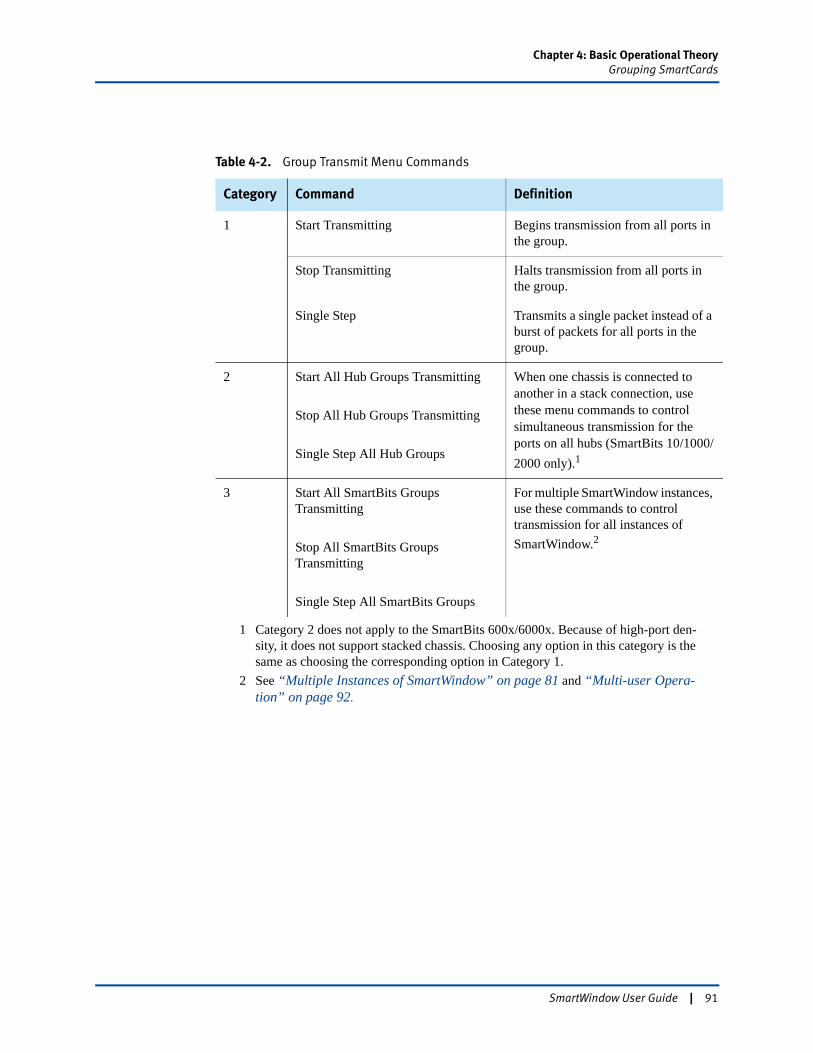
Chapter 4: Basic Operational TheoryGrouping SmartCards
Table 4-2. Group Transmit Menu Commands
Category Command Definition
1 Start Transmitting Begins transmission from all ports in the group.
Stop Transmitting Halts transmission from all ports in the group.
Single Step Transmits a single packet instead of a burst of packets for all ports in the group.
2 Start All Hub Groups Transmitting
Stop All Hub Groups Transmitting
Single Step All Hub Groups
When one chassis is connected to another in a stack connection, use these menu commands to control simultaneous transmission for the ports on all hubs (SmartBits 10/1000/2000 only).1
1 Category 2 does not apply to the SmartBits 600x/6000x. Because of high-port den-sity, it does not support stacked chassis. Choosing any option in this category is the same as choosing the corresponding option in Category 1.
3 Start All SmartBits Groups Transmitting
Stop All SmartBits Groups Transmitting
Single Step All SmartBits Groups
For multiple SmartWindow instances, use these commands to control transmission for all instances of SmartWindow.2
2 See “Multiple Instances of SmartWindow” on page 81 and “Multi-user Opera-tion” on page 92.
SmartWindow User Guide | 91
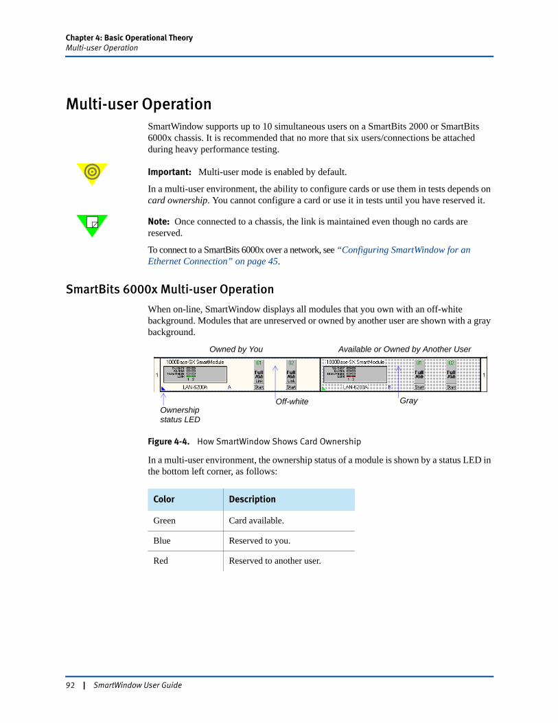
Chapter 4: Basic Operational TheoryMulti-user Operation
Multi-user OperationSmartWindow supports up to 10 simultaneous users on a SmartBits 2000 or SmartBits 6000x chassis. It is recommended that no more that six users/connections be attached during heavy performance testing.
Important: Multi-user mode is enabled by default.
In a multi-user environment, the ability to configure cards or use them in tests depends on card ownership. You cannot configure a card or use it in tests until you have reserved it.
Note: Once connected to a chassis, the link is maintained even though no cards are reserved.
To connect to a SmartBits 6000x over a network, see “Configuring SmartWindow for an Ethernet Connection” on page 45.
SmartBits 6000x Multi-user Operation
When on-line, SmartWindow displays all modules that you own with an off-white background. Modules that are unreserved or owned by another user are shown with a gray background.
Figure 4-4. How SmartWindow Shows Card Ownership
In a multi-user environment, the ownership status of a module is shown by a status LED in the bottom left corner, as follows:
Color Description
Green Card available.
Blue Reserved to you.
Red Reserved to another user.
Owned by You Available or Owned by Another User
Off-white GrayOwnershipstatus LED
92 | SmartWindow User Guide
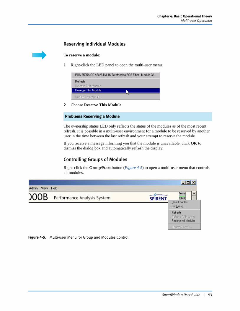
Chapter 4: Basic Operational TheoryMulti-user Operation
Reserving Individual Modules
To reserve a module:
1 Right-click the LED panel to open the multi-user menu.
2 Choose Reserve This Module.
Problems Reserving a Module
The ownership status LED only reflects the status of the modules as of the most recent refresh. It is possible in a multi-user environment for a module to be reserved by another user in the time between the last refresh and your attempt to reserve the module.
If you receive a message informing you that the module is unavailable, click OK to dismiss the dialog box and automatically refresh the display.
Controlling Groups of Modules
Right-click the Group/Start button (Figure 4-5) to open a multi-user menu that controls all modules.
Figure 4-5. Multi-user Menu for Group and Modules Control
SmartWindow User Guide | 93
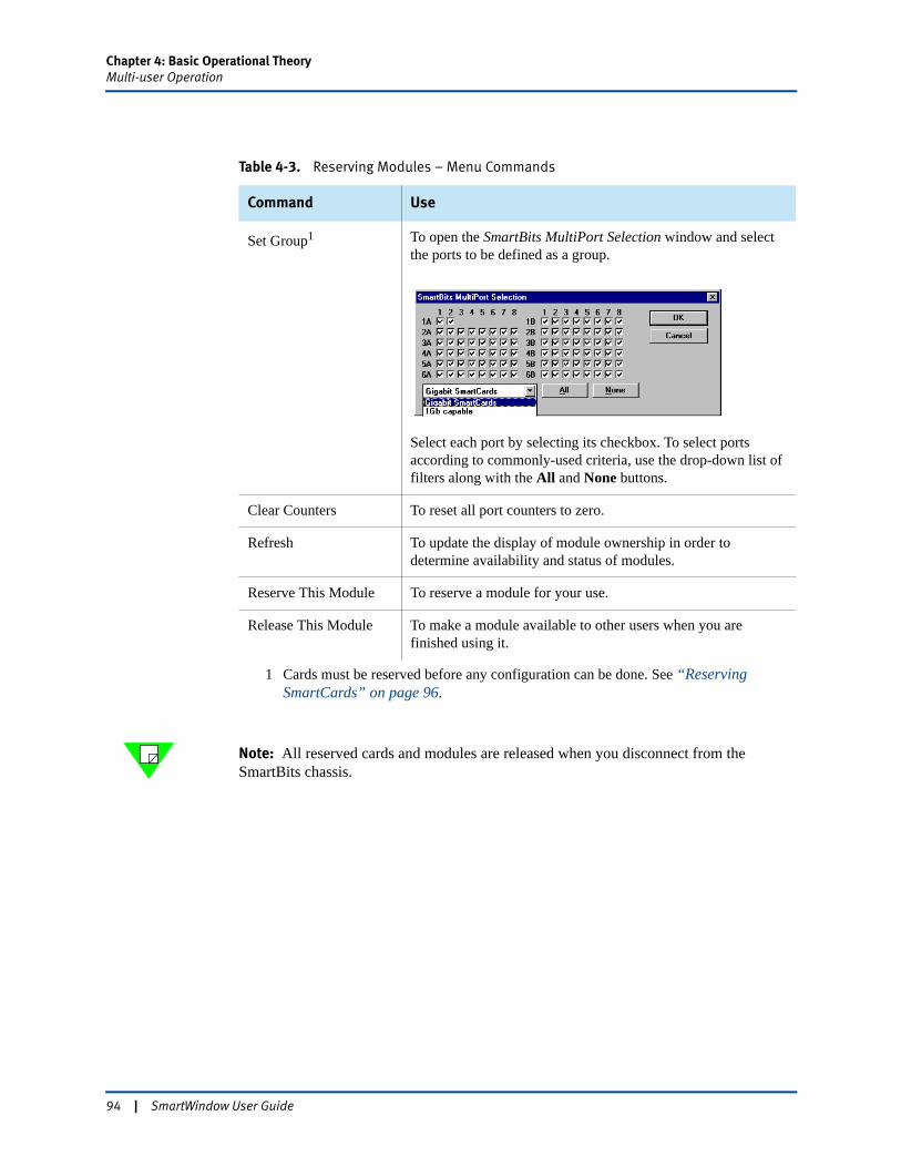
Chapter 4: Basic Operational TheoryMulti-user Operation
Note: All reserved cards and modules are released when you disconnect from the SmartBits chassis.
Table 4-3. Reserving Modules – Menu Commands
Command Use
Set Group1
1 Cards must be reserved before any configuration can be done. See “Reserving SmartCards” on page 96.
To open the SmartBits MultiPort Selection window and select the ports to be defined as a group.
Select each port by selecting its checkbox. To select ports according to commonly-used criteria, use the drop-down list of filters along with the All and None buttons.
Clear Counters To reset all port counters to zero.
Refresh To update the display of module ownership in order to determine availability and status of modules.
Reserve This Module To reserve a module for your use.
Release This Module To make a module available to other users when you are finished using it.
94 | SmartWindow User Guide
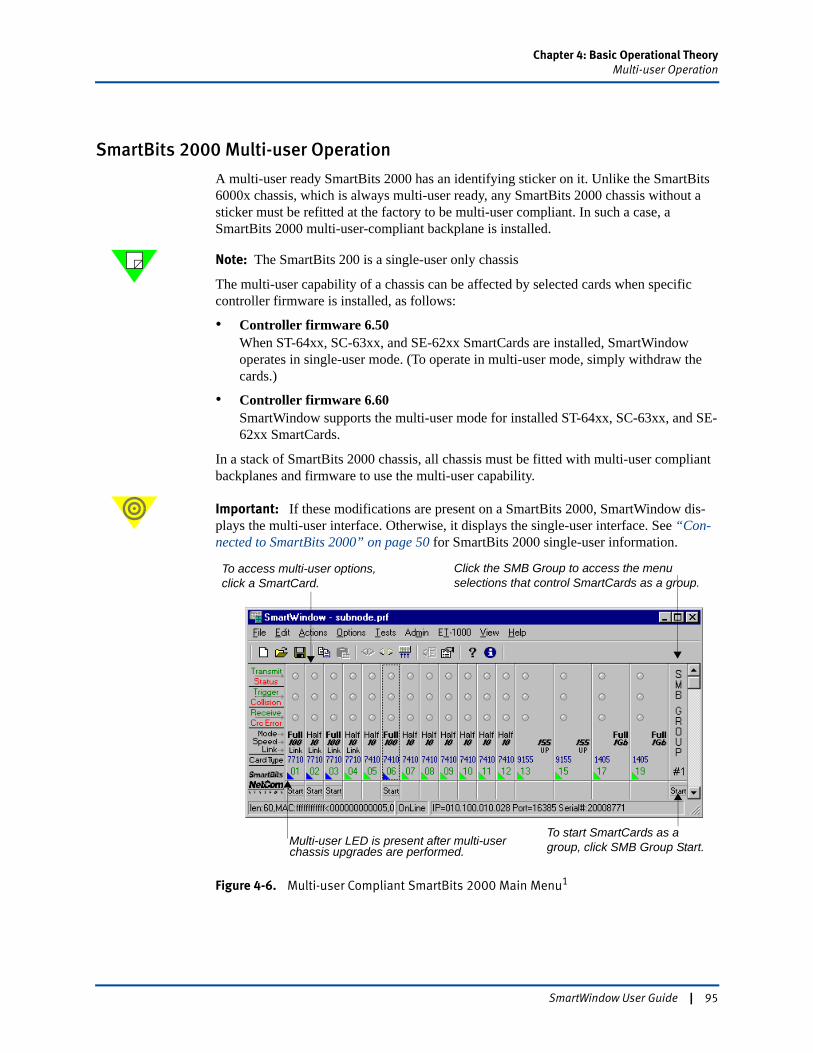
Chapter 4: Basic Operational TheoryMulti-user Operation
SmartBits 2000 Multi-user Operation
A multi-user ready SmartBits 2000 has an identifying sticker on it. Unlike the SmartBits 6000x chassis, which is always multi-user ready, any SmartBits 2000 chassis without a sticker must be refitted at the factory to be multi-user compliant. In such a case, a SmartBits 2000 multi-user-compliant backplane is installed.
Note: The SmartBits 200 is a single-user only chassis
The multi-user capability of a chassis can be affected by selected cards when specific controller firmware is installed, as follows:
• Controller firmware 6.50When ST-64xx, SC-63xx, and SE-62xx SmartCards are installed, SmartWindow operates in single-user mode. (To operate in multi-user mode, simply withdraw the cards.)
• Controller firmware 6.60SmartWindow supports the multi-user mode for installed ST-64xx, SC-63xx, and SE-62xx SmartCards.
In a stack of SmartBits 2000 chassis, all chassis must be fitted with multi-user compliant backplanes and firmware to use the multi-user capability.
Important: If these modifications are present on a SmartBits 2000, SmartWindow dis-plays the multi-user interface. Otherwise, it displays the single-user interface. See “Con-nected to SmartBits 2000” on page 50 for SmartBits 2000 single-user information.
Figure 4-6. Multi-user Compliant SmartBits 2000 Main Menu1
Click the SMB Group to access the menu selections that control SmartCards as a group.
To access multi-user options, click a SmartCard.
To start SmartCards as a group, click SMB Group Start.Multi-user LED is present after multi-user
chassis upgrades are performed.
SmartWindow User Guide | 95

Chapter 4: Basic Operational TheoryMulti-user Operation
Reserving SmartCards
To reserve cards in a SmartBits 2000 that is multi-user compliant:
1 Start SmartWindow. As shown in Figure 4-6, the multi-user main menu has an addi-tional LED.
2 Right-click a card to reserve it.The following dialog box appears.
3 Choose Reserve SmartCard.The LED changes from green to blue. Use this same process for reserving designated SmartCards individually.1
4 To reserve all cards, right-click the SMB Group panel.
5 Choose Reserve All SmartCards.
Note: Cards cannot be grouped or configured until you have reserved them. Clicking an unreserved card displays no configuration options; the card must first be reserved. Cards reserved by other users are released on disconnect.
1. See “SmartBits 6000x Multi-user Operation” on page 92 for information on color-coding.1. See “Connected to SmartBits 600x/6000x” on page 53 for information on LED color-cod-
ing.
For reserving cards on a single chassis
For reserving cards on up to four chassis
when you are connected to only one.
when you are connected to more than one.
96 | SmartWindow User Guide
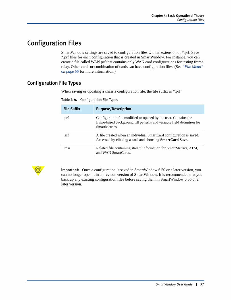
Chapter 4: Basic Operational TheoryConfiguration Files
Configuration FilesSmartWindow settings are saved to configuration files with an extension of *.prf. Save *.prf files for each configuration that is created in SmartWindow. For instance, you can create a file called WAN.prf that contains only WAN card configurations for testing frame relay. Other cards or combination of cards can have configuration files. (See “File Menu” on page 55 for more information.)
Configuration File Types
When saving or updating a chassis configuration file, the file suffix is *.prf.
Important: Once a configuration is saved in SmartWindow 6.50 or a later version, you can no longer open it in a previous version of SmartWindow. It is recommended that you back up any existing configuration files before saving them in SmartWindow 6.50 or a later version.
Table 4-4. Configuration File Types
File Suffix Purpose/Description
.prf Configuration file modified or opened by the user. Contains the frame-based background fill patterns and variable field definition for SmartMetrics.
.scf A file created when an individual SmartCard configuration is saved. Accessed by clicking a card and choosing SmartCard Save.
.msi Related file containing stream information for SmartMetrics, ATM, and WAN SmartCards.
SmartWindow User Guide | 97
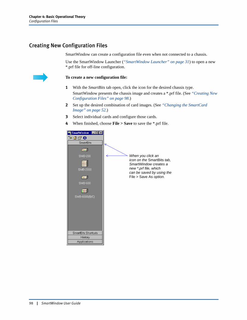
Chapter 4: Basic Operational TheoryConfiguration Files
Creating New Configuration Files
SmartWindow can create a configuration file even when not connected to a chassis.
Use the SmartWindow Launcher (“SmartWindow Launcher” on page 31) to open a new *.prf file for off-line configuration.
To create a new configuration file:
1 With the SmartBits tab open, click the icon for the desired chassis type.SmartWindow presents the chassis image and creates a *.prf file. (See “Creating New Configuration Files” on page 98.)
2 Set up the desired combination of card images. (See “Changing the SmartCard Image” on page 52.)
3 Select individual cards and configure those cards.4 When finished, choose File > Save to save the *.prf file.
When you click anicon on the SmartBits tab,SmartWindow creates anew *.prf file, which can be saved by using theFile > Save As option.
98 | SmartWindow User Guide
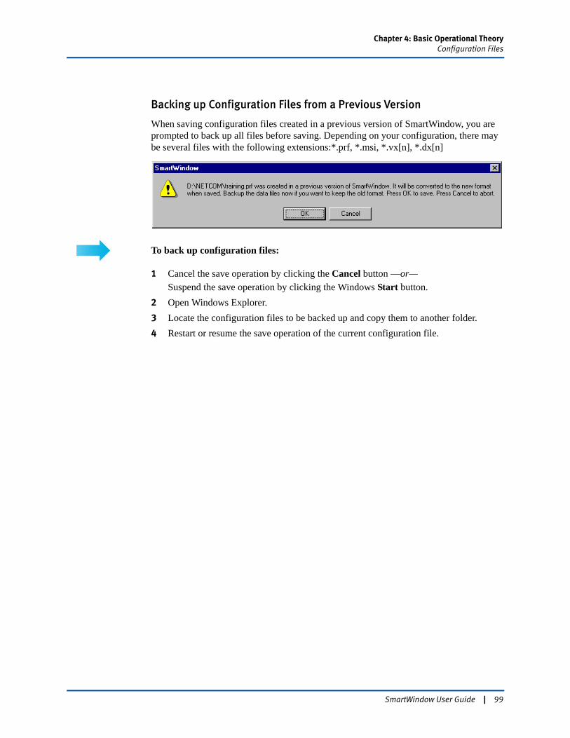
Chapter 4: Basic Operational TheoryConfiguration Files
Backing up Configuration Files from a Previous Version
When saving configuration files created in a previous version of SmartWindow, you are prompted to back up all files before saving. Depending on your configuration, there may be several files with the following extensions:*.prf, *.msi, *.vx[n], *.dx[n]
To back up configuration files:
1 Cancel the save operation by clicking the Cancel button —or—Suspend the save operation by clicking the Windows Start button.
2 Open Windows Explorer. 3 Locate the configuration files to be backed up and copy them to another folder.4 Restart or resume the save operation of the current configuration file.
SmartWindow User Guide | 99
Chapter 4: Basic Operational TheoryConfiguration Files
Updating a Configuration
The SmartBits configuration is stored both on the SmartCards and in configuration files on the manager workstation. Update the SmartBits system by updating the chassis using a selected *.prf configuration file. When the file is sent to the chassis, each SmartCard is reconfigured.
The configuration can also be maintained from another application, such as SmartApplications or SmartLibrary, or from another SmartWindow session. For example, you can run a customized test application, then open SmartWindow without losing the previous settings.
Update Process
Downloading a preference file to a SmartBits chassis and SmartCard system is referred to as updating SmartBits or updating for short. Updating is the process of configuring the SmartBits hardware after configuring parameters in SmartWindow.
The length of the update process depends upon the type of card, number of cards, and streams per card. Once the update is complete, the configuration may be modified or saved.
Update Steps
• To Automatically Update – Not applicable to the SmartBits 600x/6000xChoose Initialize Ports after Connect and/or Initialize Ports after File/Open option on the SmartWindow Preferences window. These options use the most current *.prf file to update the system.
• To Keep the Previous ConfigurationClear the Initialize Ports after Connect and/or Initialize Ports after File/Open checkboxes in the SmartWindow Preferences window.
• To Update ManuallyChoose File > Open and select a *.prf file.
• To Update after ConfiguringIf configuration changes have been made to a specified card, the currently active configuration file does not reflect the changes unless updated. To update a card, click the Download button on the SmartWindow toolbar.
100 | SmartWindow User Guide
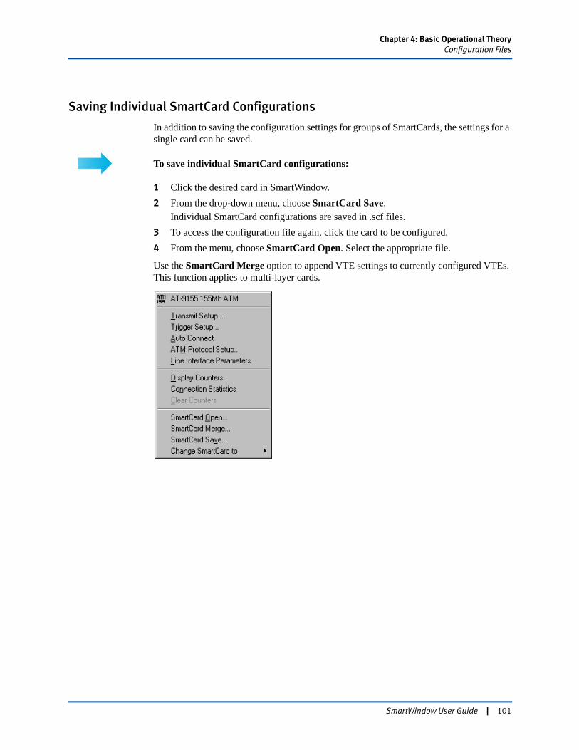
Chapter 4: Basic Operational TheoryConfiguration Files
Saving Individual SmartCard Configurations
In addition to saving the configuration settings for groups of SmartCards, the settings for a single card can be saved.
To save individual SmartCard configurations:
1 Click the desired card in SmartWindow.2 From the drop-down menu, choose SmartCard Save.
Individual SmartCard configurations are saved in .scf files.3 To access the configuration file again, click the card to be configured.4 From the menu, choose SmartCard Open. Select the appropriate file.
Use the SmartCard Merge option to append VTE settings to currently configured VTEs. This function applies to multi-layer cards.
SmartWindow User Guide | 101
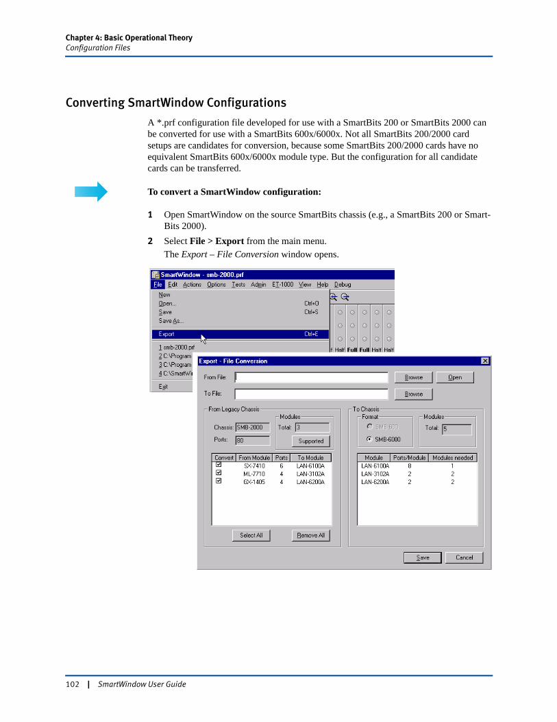
Chapter 4: Basic Operational TheoryConfiguration Files
Converting SmartWindow Configurations
A *.prf configuration file developed for use with a SmartBits 200 or SmartBits 2000 can be converted for use with a SmartBits 600x/6000x. Not all SmartBits 200/2000 card setups are candidates for conversion, because some SmartBits 200/2000 cards have no equivalent SmartBits 600x/6000x module type. But the configuration for all candidate cards can be transferred.
To convert a SmartWindow configuration:
1 Open SmartWindow on the source SmartBits chassis (e.g., a SmartBits 200 or Smart-Bits 2000).
2 Select File > Export from the main menu.The Export – File Conversion window opens.
102 | SmartWindow User Guide
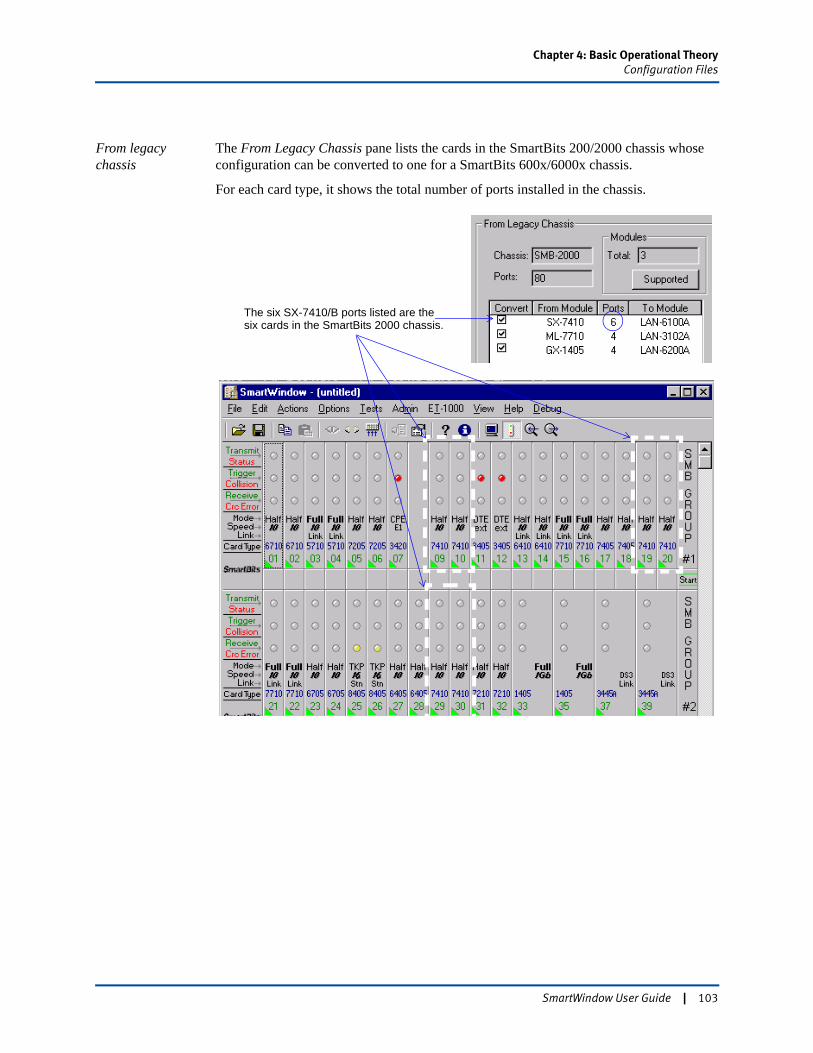
Chapter 4: Basic Operational TheoryConfiguration Files
From legacy chassis
The From Legacy Chassis pane lists the cards in the SmartBits 200/2000 chassis whose configuration can be converted to one for a SmartBits 600x/6000x chassis.
For each card type, it shows the total number of ports installed in the chassis.
The six SX-7410/B ports listed are the six cards in the SmartBits 2000 chassis.
SmartWindow User Guide | 103
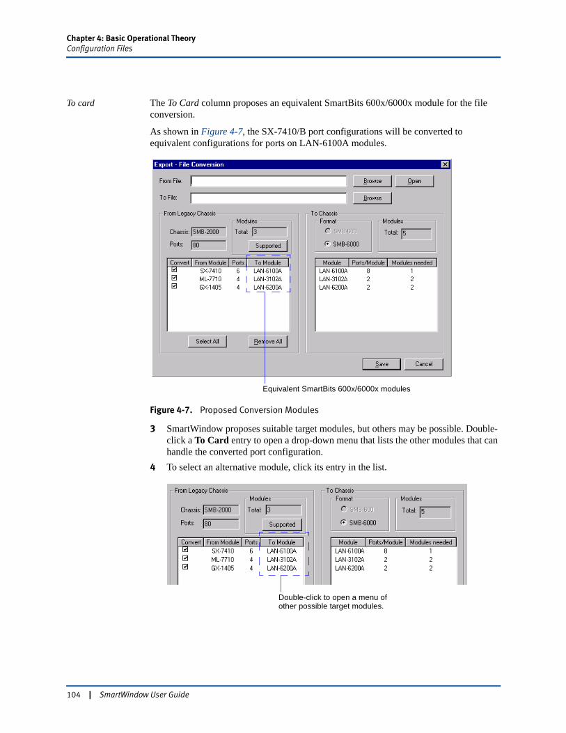
Chapter 4: Basic Operational TheoryConfiguration Files
To card The To Card column proposes an equivalent SmartBits 600x/6000x module for the file conversion.
As shown in Figure 4-7, the SX-7410/B port configurations will be converted to equivalent configurations for ports on LAN-6100A modules.
Figure 4-7. Proposed Conversion Modules
3 SmartWindow proposes suitable target modules, but others may be possible. Double-click a To Card entry to open a drop-down menu that lists the other modules that can handle the converted port configuration.
4 To select an alternative module, click its entry in the list.
Equivalent SmartBits 600x/6000x modules
Double-click to open a menu of other possible target modules.
104 | SmartWindow User Guide
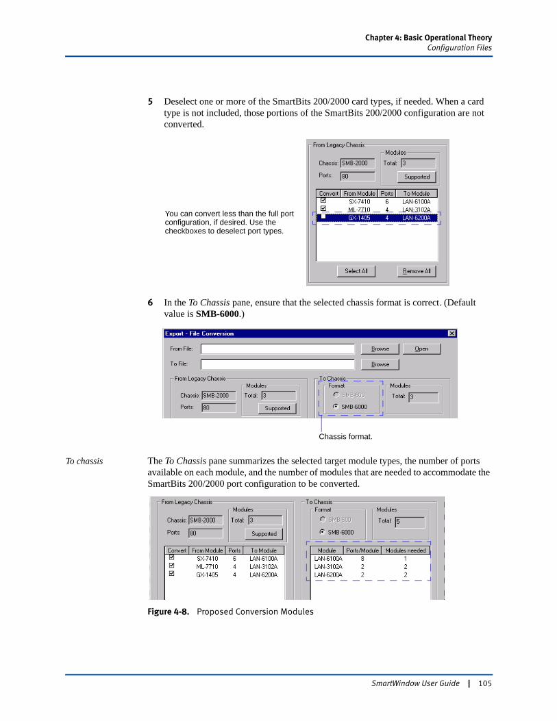
Chapter 4: Basic Operational TheoryConfiguration Files
5 Deselect one or more of the SmartBits 200/2000 card types, if needed. When a card type is not included, those portions of the SmartBits 200/2000 configuration are not converted.
6 In the To Chassis pane, ensure that the selected chassis format is correct. (Default value is SMB-6000.)
To chassis The To Chassis pane summarizes the selected target module types, the number of ports available on each module, and the number of modules that are needed to accommodate the SmartBits 200/2000 port configuration to be converted.
Figure 4-8. Proposed Conversion Modules
You can convert less than the full port configuration, if desired. Use the checkboxes to deselect port types.
Chassis format.
SmartWindow User Guide | 105
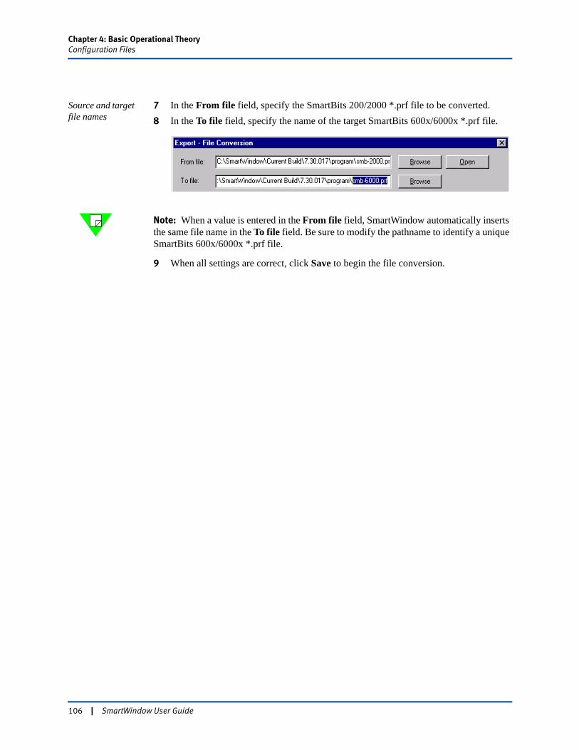
Chapter 4: Basic Operational TheoryConfiguration Files
Source and target file names
7 In the From file field, specify the SmartBits 200/2000 *.prf file to be converted.8 In the To file field, specify the name of the target SmartBits 600x/6000x *.prf file.
Note: When a value is entered in the From file field, SmartWindow automatically inserts the same file name in the To file field. Be sure to modify the pathname to identify a unique SmartBits 600x/6000x *.prf file.
9 When all settings are correct, click Save to begin the file conversion.
106 | SmartWindow User Guide
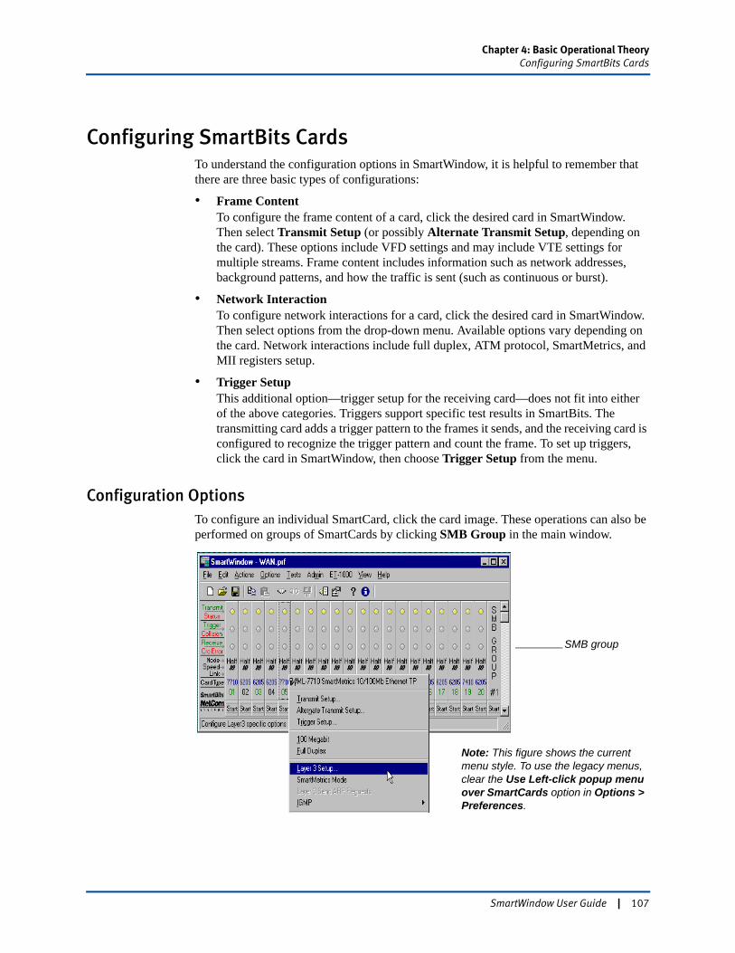
Chapter 4: Basic Operational TheoryConfiguring SmartBits Cards
Configuring SmartBits CardsTo understand the configuration options in SmartWindow, it is helpful to remember that there are three basic types of configurations:
• Frame ContentTo configure the frame content of a card, click the desired card in SmartWindow. Then select Transmit Setup (or possibly Alternate Transmit Setup, depending on the card). These options include VFD settings and may include VTE settings for multiple streams. Frame content includes information such as network addresses, background patterns, and how the traffic is sent (such as continuous or burst).
• Network InteractionTo configure network interactions for a card, click the desired card in SmartWindow. Then select options from the drop-down menu. Available options vary depending on the card. Network interactions include full duplex, ATM protocol, SmartMetrics, and MII registers setup.
• Trigger SetupThis additional option—trigger setup for the receiving card—does not fit into either of the above categories. Triggers support specific test results in SmartBits. The transmitting card adds a trigger pattern to the frames it sends, and the receiving card is configured to recognize the trigger pattern and count the frame. To set up triggers, click the card in SmartWindow, then choose Trigger Setup from the menu.
Configuration OptionsTo configure an individual SmartCard, click the card image. These operations can also be performed on groups of SmartCards by clicking SMB Group in the main window.
SMB group
Note: This figure shows the current menu style. To use the legacy menus, clear the Use Left-click popup menu over SmartCards option in Options > Preferences.
SmartWindow User Guide | 107
Chapter 4: Basic Operational TheoryConfiguring SmartBits Cards
Configuring Frame Content
Use these options to configure the content of the frames to be transmitted from each SmartCard:
• Traditional/ Frame-Based ModeClick the card in SmartWindow, then choose Options > Transmit Setup.
• SmartMetrics/ Stream-Based ModeClick the card in SmartWindow, choose Options > SmartMetrics Mode, then choose Transmit Setup.• To edit global options, click This Port. Global options include the group of VFD
3s that cycle in each stream.• To edit individual streams (VTEs), select the stream(s) to be edited, and click
Selected VTEs.
• ATM SmartCardsClick the card in SmartWindow. Then choose Options > Transmit Setup.
Configuring Network Interactions
To configure network interactions for a card, click the desired card in SmartWindow. Then select the feature group to be viewed or edited. Network interactions include options such as full duplex, ATM protocol, SmartMetrics, and MII registers setup.
For more information, see the SmartBits System Overview & Reference Guide.
108 | SmartWindow User Guide
Chapter 4: Basic Operational TheoryTypes of Tests
Types of TestsSmartWindow includes these types of tests:
• Manual Setup TestsTo run these tests, first configure the frame content (in transmit setup), the network interactions, and the triggers for each SmartCard. Once the configurations are complete, run the test by starting transmission:• From all cards in the chassis by selecting Actions > Start All Cards from the
main menu.• From an individual card by clicking Start on the appropriate SmartCard in
SmartWindow.• From a group of cards by defining the group, then clicking Start on the far-right
group SmartCard.
• SmartMetrics TestsThese stream-based tests use Layer 3 and some Layer 2 protocols. These tests are available from the main menu (Tests > SmartMetrics Tests). SmartMetrics tests offer specific test methodology and results based on the type of test. For more information, refer to Chapter 7, “SmartMetrics Testing.”
View test results during the transmission process or after the test is completed, depending on the type of results to be viewed.
SmartWindow User Guide | 109

110 | SmartWindow User Guide
Chapter 5
Advanced Operational Theory
SmartWindow supports more advanced operations, in addition to the configuration options presented in Chapter 4, “Basic Operational Theory.” This chapter provides information on these important features.
In this chapter...
• Setting up IP Multicast Groups . . . . 112
• SmartCounters . . . . 131
• SmartCounters Toolbar . . . . 137
• Smartbit.ini Files . . . . 142
• Using Triggers and Capture . . . . 145
• Sending Ping, SNMP, and RIP Frames . . . . 156
• Editing Frames . . . . 157
• MII Registers . . . . 163
• Using the Data Decoder . . . . 167
• Testing with IPv6 Streams . . . . 169
• Jumbo Frames . . . . 184
• Virtual Flow Cyclic ARPs and ARP Requests . . . . 186
• Gratuitous ARP Mode . . . . 196
SmartWindow User Guide | 111
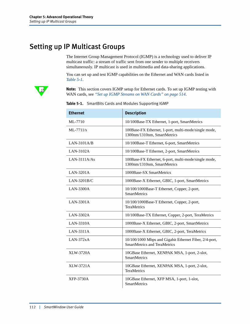
Chapter 5: Advanced Operational TheorySetting up IP Multicast Groups
Setting up IP Multicast GroupsThe Internet Group Management Protocol (IGMP) is a technology used to deliver IP multicast traffic: a stream of traffic sent from one sender to multiple receivers simultaneously. IP multicast is used in multimedia and data-sharing applications.
You can set up and test IGMP capabilities on the Ethernet and WAN cards listed in Table 5-1.
Note: This section covers IGMP setup for Ethernet cards. To set up IGMP testing with WAN cards, see “Set up IGMP Streams on WAN Cards” on page 514.
Table 5-1. SmartBits Cards and Modules Supporting IGMP
Ethernet Description
ML-7710 10/100Base-TX Ethernet, 1-port, SmartMetrics
ML-7711/s 100Base-FX Ethernet, 1-port, multi-mode/single mode, 1300nm/1310nm, SmartMetrics
LAN-3101A/B 10/100Base-T Ethernet, 6-port, SmartMetrics
LAN-3102A 10/100Base-T Ethernet, 2-port, SmartMetrics
LAN-3111A/As 100Base-FX Ethernet, 6-port, multi-mode/single mode, 1300nm/1310nm, SmartMetrics
LAN-3201A 1000Base-SX SmartMetrics
LAN-3201B/C 1000Base-X Ethernet, GBIC, 1-port, SmartMetrics
LAN-3300A 10/100/1000Base-T Ethernet, Copper, 2-port, SmartMetrics
LAN-3301A 10/100/1000Base-T Ethernet, Copper, 2-port, TeraMetrics
LAN-3302A 10/100Base-TX Ethernet, Copper, 2-port, TeraMetrics
LAN-3310A 1000Base-X Ethernet, GBIC, 2-port, SmartMetrics
LAN-3311A 1000Base-X Ethernet, GBIC, 2-port, TeraMetrics
LAN-372xA 10/100/1000 Mbps and Gigabit Ethernet Fiber, 2/4-port, SmartMetrics and TeraMetrics
XLW-3720A 10GBase Ethernet, XENPAK MSA, 1-port, 2-slot, SmartMetrics
XLW-3721A 10GBase Ethernet, XENPAK MSA, 1-port, 2-slot, TeraMetrics
XFP-3730A 10GBase Ethernet, XFP MSA, 1-port, 1-slot, SmartMetrics
112 | SmartWindow User Guide
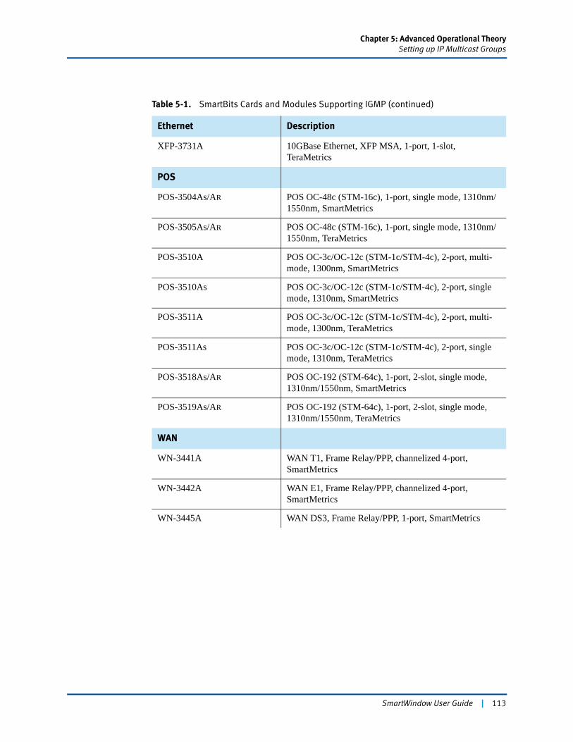
Chapter 5: Advanced Operational TheorySetting up IP Multicast Groups
Ethernet Description
XFP-3731A 10GBase Ethernet, XFP MSA, 1-port, 1-slot, TeraMetrics
POS
POS-3504As/AR POS OC-48c (STM-16c), 1-port, single mode, 1310nm/1550nm, SmartMetrics
POS-3505As/AR POS OC-48c (STM-16c), 1-port, single mode, 1310nm/1550nm, TeraMetrics
POS-3510A POS OC-3c/OC-12c (STM-1c/STM-4c), 2-port, multi- mode, 1300nm, SmartMetrics
POS-3510As POS OC-3c/OC-12c (STM-1c/STM-4c), 2-port, single mode, 1310nm, SmartMetrics
POS-3511A POS OC-3c/OC-12c (STM-1c/STM-4c), 2-port, multi- mode, 1300nm, TeraMetrics
POS-3511As POS OC-3c/OC-12c (STM-1c/STM-4c), 2-port, single mode, 1310nm, TeraMetrics
POS-3518As/AR POS OC-192 (STM-64c), 1-port, 2-slot, single mode, 1310nm/1550nm, SmartMetrics
POS-3519As/AR POS OC-192 (STM-64c), 1-port, 2-slot, single mode, 1310nm/1550nm, TeraMetrics
WAN
WN-3441A WAN T1, Frame Relay/PPP, channelized 4-port, SmartMetrics
WN-3442A WAN E1, Frame Relay/PPP, channelized 4-port, SmartMetrics
WN-3445A WAN DS3, Frame Relay/PPP, 1-port, SmartMetrics
Table 5-1. SmartBits Cards and Modules Supporting IGMP (continued)
SmartWindow User Guide | 113
Chapter 5: Advanced Operational TheorySetting up IP Multicast Groups
About IGMP
IGMP provides a way for a host to inform a network forwarding device of its desire to receive IP multicast traffic, i.e., traffic that is sent from one source to many destinations. In addition, it enables group information and multicast forwarding tables to be maintained dynamically.
To join a group, a host sends an IGMP membership request (join request). In IGMP Version 1, a joined host needed to respond to periodic router queries to maintain its membership status. If the host failed to respond to queries for a specified time interval, its membership timed out and was removed. (The port must be in SmartMetrics mode with at least one stream configured for the LAN-3101A/B cards to receive IGMP queries.)
IGMP Version 2, an updated version, allows hosts to leave groups explicitly by sending a leave request. This offers a more efficient mechanism because it minimizes the quantity of unwanted traffic forwarded to the host.
IGMP Version 3 allows a requesting host to specify a list of hosts from which it wishes to receive traffic. Traffic from other hosts is blocked inside the network. IPv6 does not currently support IGMP.
IGMP in SmartWindow
Using any of the cards listed in Table 5-1, individual multicast streams can be configured in one port, as well as all streams on a port or all ports on the card. Each multicast stream acts as a member in an IP multicast group.
SmartWindow options include using IGMP Version 1, Version 2, or Version 3 for streams, commands to join and leave an IP multicast group, and a command to reset the IGMP stack when switching versions.
See “How IP and MAC Addresses Identify Multicast Traffic” on page 115 for overview information on IGMP addressing.
Setup Menus
The menus and options used to set up multicast streams differ depending on card type.
ML-7710 and other SmartBits 200/2000 SmartCards
For ML-7710 and the related SmartCard for SmartBits 200/2000, see “Set up Multicast Streams on SmartBits 200/2000 SmartCards” (page 116 through page 129) for setup information. The IGMP menu options on these cards become enabled when one or more IP multicast streams are configured.
SmartBits 600x/6000x TeraMetrics and SmartMetrics modules
With SmartBits 600x and SmartBits 6000x/6000x modules, use the IGMP Management window to set up IGMP groups. This window provides access to all ports in the chassis, in one view. It also displays statistics and log information. See “Set up IGMP for SmartBits 600x/6000x Modules” (page 120 and following pages) for setup information.
114 | SmartWindow User Guide
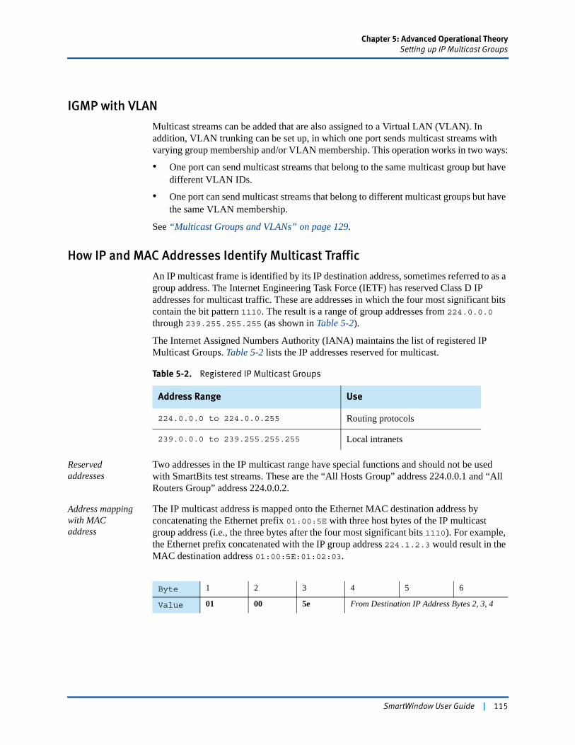
Chapter 5: Advanced Operational TheorySetting up IP Multicast Groups
IGMP with VLAN
Multicast streams can be added that are also assigned to a Virtual LAN (VLAN). In addition, VLAN trunking can be set up, in which one port sends multicast streams with varying group membership and/or VLAN membership. This operation works in two ways:
• One port can send multicast streams that belong to the same multicast group but have different VLAN IDs.
• One port can send multicast streams that belong to different multicast groups but have the same VLAN membership.
See “Multicast Groups and VLANs” on page 129.
How IP and MAC Addresses Identify Multicast Traffic
An IP multicast frame is identified by its IP destination address, sometimes referred to as a group address. The Internet Engineering Task Force (IETF) has reserved Class D IP addresses for multicast traffic. These are addresses in which the four most significant bits contain the bit pattern 1110. The result is a range of group addresses from 224.0.0.0 through 239.255.255.255 (as shown in Table 5-2).
The Internet Assigned Numbers Authority (IANA) maintains the list of registered IP Multicast Groups. Table 5-2 lists the IP addresses reserved for multicast.
Reserved addresses
Two addresses in the IP multicast range have special functions and should not be used with SmartBits test streams. These are the “All Hosts Group” address 224.0.0.1 and “All Routers Group” address 224.0.0.2.
Address mapping with MAC address
The IP multicast address is mapped onto the Ethernet MAC destination address by concatenating the Ethernet prefix 01:00:5E with three host bytes of the IP multicast group address (i.e., the three bytes after the four most significant bits 1110). For example, the Ethernet prefix concatenated with the IP group address 224.1.2.3 would result in the MAC destination address 01:00:5E:01:02:03.
Table 5-2. Registered IP Multicast Groups
Address Range Use
224.0.0.0 to 224.0.0.255 Routing protocols
239.0.0.0 to 239.255.255.255 Local intranets
Byte 1 2 3 4 5 6
Value 01 00 5e From Destination IP Address Bytes 2, 3, 4
SmartWindow User Guide | 115
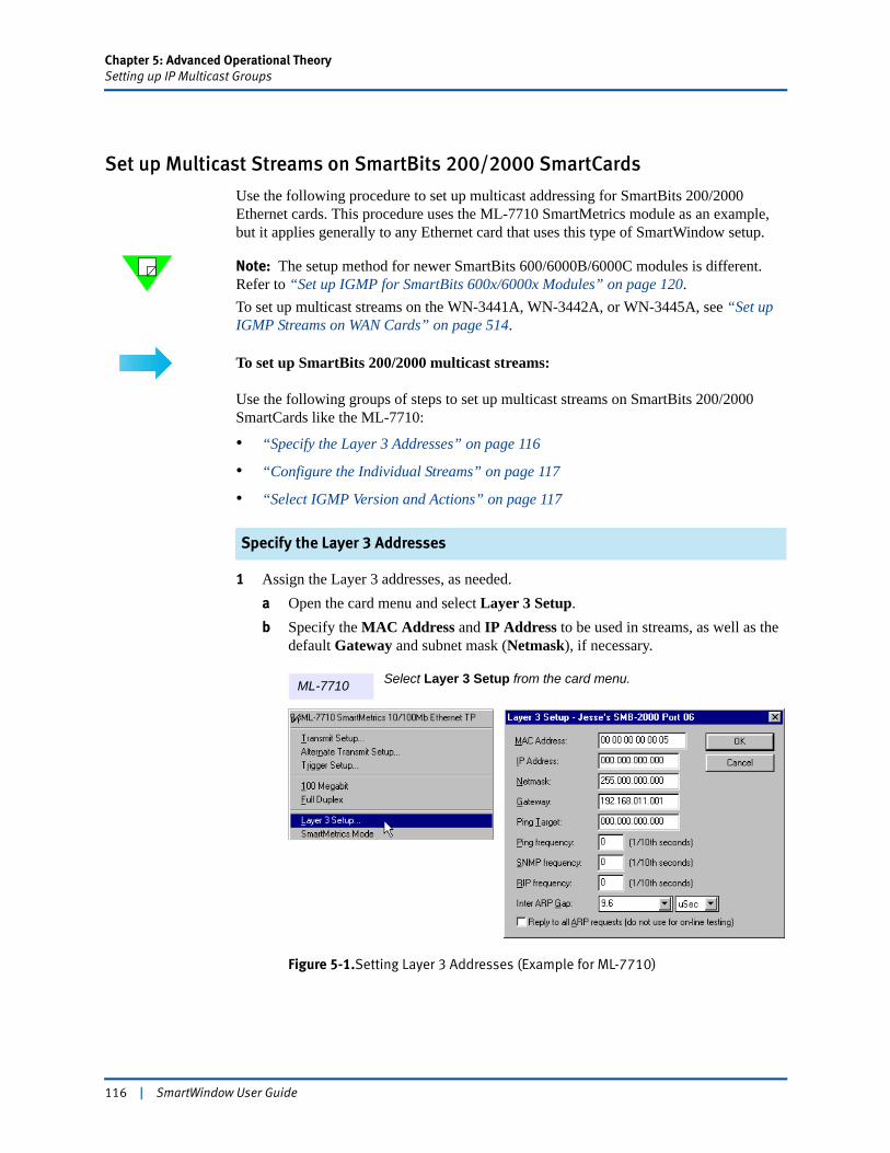
Chapter 5: Advanced Operational TheorySetting up IP Multicast Groups
Set up Multicast Streams on SmartBits 200/2000 SmartCards
Use the following procedure to set up multicast addressing for SmartBits 200/2000 Ethernet cards. This procedure uses the ML-7710 SmartMetrics module as an example, but it applies generally to any Ethernet card that uses this type of SmartWindow setup.
Note: The setup method for newer SmartBits 600/6000B/6000C modules is different. Refer to “Set up IGMP for SmartBits 600x/6000x Modules” on page 120.To set up multicast streams on the WN-3441A, WN-3442A, or WN-3445A, see “Set up IGMP Streams on WAN Cards” on page 514.
To set up SmartBits 200/2000 multicast streams:
Use the following groups of steps to set up multicast streams on SmartBits 200/2000 SmartCards like the ML-7710:
• “Specify the Layer 3 Addresses” on page 116
• “Configure the Individual Streams” on page 117
• “Select IGMP Version and Actions” on page 117
Specify the Layer 3 Addresses
1 Assign the Layer 3 addresses, as needed.a Open the card menu and select Layer 3 Setup.b Specify the MAC Address and IP Address to be used in streams, as well as the
default Gateway and subnet mask (Netmask), if necessary.
Figure 5-1.Setting Layer 3 Addresses (Example for ML-7710)
Select Layer 3 Setup from the card menu.ML-7710
116 | SmartWindow User Guide
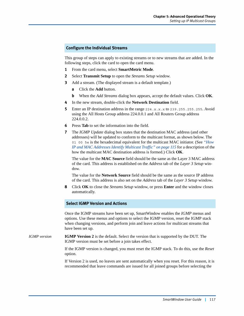
Chapter 5: Advanced Operational TheorySetting up IP Multicast Groups
Configure the Individual Streams
This group of steps can apply to existing streams or to new streams that are added. In the following steps, click the card to open the card menu.1 From the card menu, select SmartMetric Mode.2 Select Transmit Setup to open the Streams Setup window.3 Add a stream. (The displayed stream is a default template.)
a Click the Add button.b When the Add Streams dialog box appears, accept the default values. Click OK.
4 In the new stream, double-click the Network Destination field.5 Enter an IP destination address in the range 224.x.x.x to 239.255.255.255. Avoid
using the All Hosts Group address 224.0.0.1 and All Routers Group address 224.0.0.2.
6 Press Tab to set the information into the field.7 The IGMP Update dialog box states that the destination MAC address (and other
addresses) will be updated to conform to the multicast format, as shown below. The 01 00 5e is the hexadecimal equivalent for the multicast MAC initiator. (See “How IP and MAC Addresses Identify Multicast Traffic” on page 115 for a description of the how the multicast MAC destination address is formed.) Click OK.The value for the MAC Source field should be the same as the Layer 3 MAC address of the card. This address is established on the Address tab of the Layer 3 Setup win-dow.The value for the Network Source field should be the same as the source IP address of the card. This address is also set on the Address tab of the Layer 3 Setup window.
8 Click OK to close the Streams Setup window, or press Enter and the window closes automatically.
Select IGMP Version and Actions
Once the IGMP streams have been set up, SmartWindow enables the IGMP menus and options. Use these menus and options to select the IGMP version, reset the IGMP stack when changing versions, and perform join and leave actions for multicast streams that have been set up.
IGMP version IGMP Version 2 is the default. Select the version that is supported by the DUT. The IGMP version must be set before a join takes effect.
If the IGMP version is changed, you must reset the IGMP stack. To do this, use the Reset option.
If Version 2 is used, no leaves are sent automatically when you reset. For this reason, it is recommended that leave commands are issued for all joined groups before selecting the
SmartWindow User Guide | 117
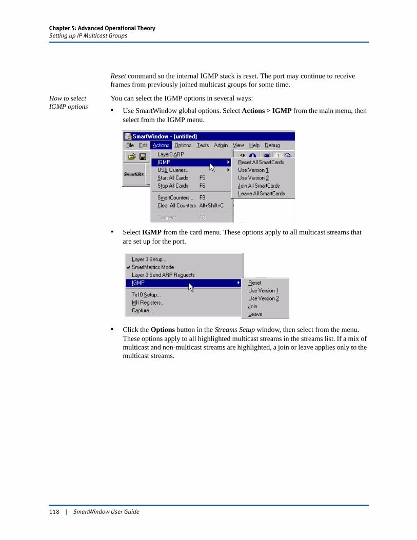
Chapter 5: Advanced Operational TheorySetting up IP Multicast Groups
Reset command so the internal IGMP stack is reset. The port may continue to receive frames from previously joined multicast groups for some time.
How to select IGMP options
You can select the IGMP options in several ways:
• Use SmartWindow global options. Select Actions > IGMP from the main menu, then select from the IGMP menu.
• Select IGMP from the card menu. These options apply to all multicast streams that are set up for the port.
• Click the Options button in the Streams Setup window, then select from the menu. These options apply to all highlighted multicast streams in the streams list. If a mix of multicast and non-multicast streams are highlighted, a join or leave applies only to the multicast streams.
118 | SmartWindow User Guide
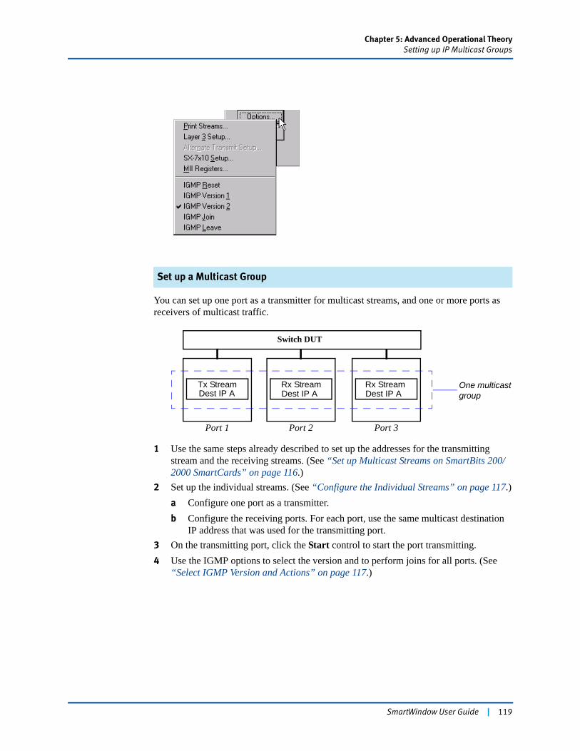
Chapter 5: Advanced Operational TheorySetting up IP Multicast Groups
Set up a Multicast Group
You can set up one port as a transmitter for multicast streams, and one or more ports as receivers of multicast traffic.
1 Use the same steps already described to set up the addresses for the transmitting stream and the receiving streams. (See “Set up Multicast Streams on SmartBits 200/2000 SmartCards” on page 116.)
2 Set up the individual streams. (See “Configure the Individual Streams” on page 117.)a Configure one port as a transmitter.b Configure the receiving ports. For each port, use the same multicast destination
IP address that was used for the transmitting port.3 On the transmitting port, click the Start control to start the port transmitting.4 Use the IGMP options to select the version and to perform joins for all ports. (See
“Select IGMP Version and Actions” on page 117.)
Port 1 Port 2 Port 3
Tx StreamDest IP ADest IP A Dest IP ARx StreamRx Stream One multicast
group
Switch DUT
SmartWindow User Guide | 119
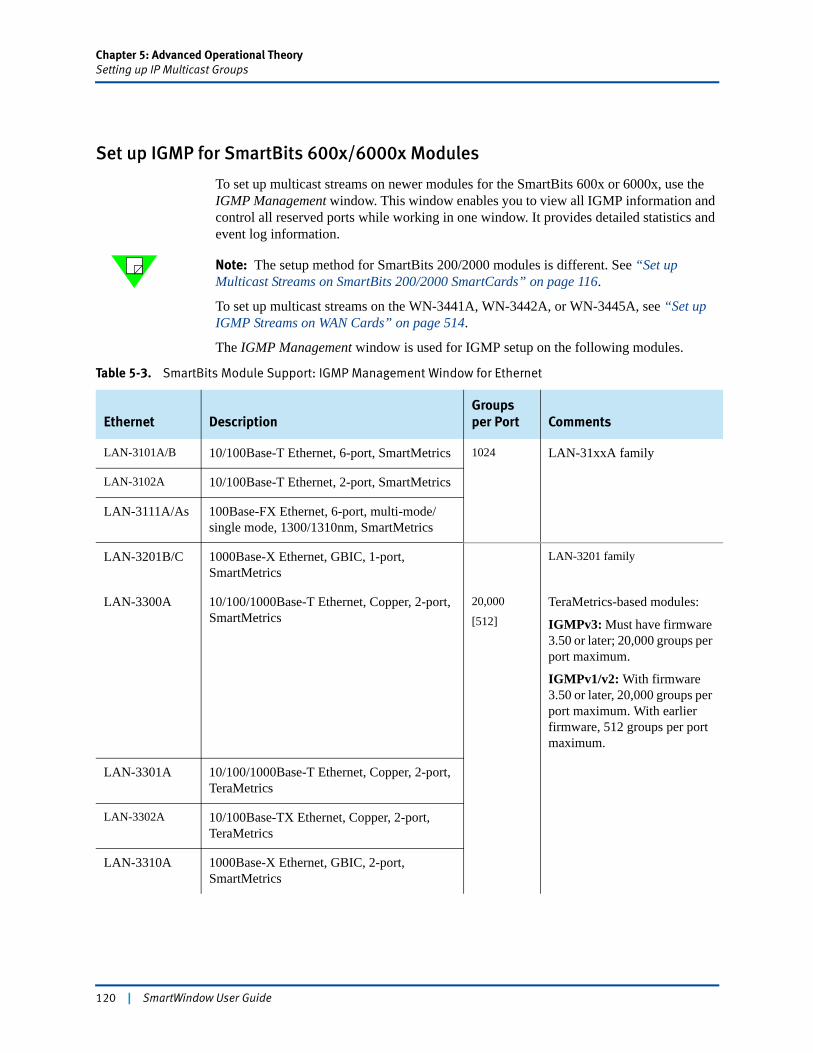
Chapter 5: Advanced Operational TheorySetting up IP Multicast Groups
Set up IGMP for SmartBits 600x/6000x Modules
To set up multicast streams on newer modules for the SmartBits 600x or 6000x, use the IGMP Management window. This window enables you to view all IGMP information and control all reserved ports while working in one window. It provides detailed statistics and event log information.
Note: The setup method for SmartBits 200/2000 modules is different. See “Set up Multicast Streams on SmartBits 200/2000 SmartCards” on page 116.
To set up multicast streams on the WN-3441A, WN-3442A, or WN-3445A, see “Set up IGMP Streams on WAN Cards” on page 514.
The IGMP Management window is used for IGMP setup on the following modules.
Table 5-3. SmartBits Module Support: IGMP Management Window for Ethernet
Ethernet DescriptionGroups per Port Comments
LAN-3101A/B 10/100Base-T Ethernet, 6-port, SmartMetrics 1024 LAN-31xxA family
LAN-3102A 10/100Base-T Ethernet, 2-port, SmartMetrics
LAN-3111A/As 100Base-FX Ethernet, 6-port, multi-mode/single mode, 1300/1310nm, SmartMetrics
LAN-3201B/C 1000Base-X Ethernet, GBIC, 1-port, SmartMetrics
LAN-3201 family
LAN-3300A 10/100/1000Base-T Ethernet, Copper, 2-port, SmartMetrics
20,000
[512]TeraMetrics-based modules:
IGMPv3: Must have firmware 3.50 or later; 20,000 groups per port maximum.
IGMPv1/v2: With firmware 3.50 or later, 20,000 groups per port maximum. With earlier firmware, 512 groups per port maximum.
LAN-3301A 10/100/1000Base-T Ethernet, Copper, 2-port, TeraMetrics
LAN-3302A 10/100Base-TX Ethernet, Copper, 2-port, TeraMetrics
LAN-3310A 1000Base-X Ethernet, GBIC, 2-port, SmartMetrics
120 | SmartWindow User Guide
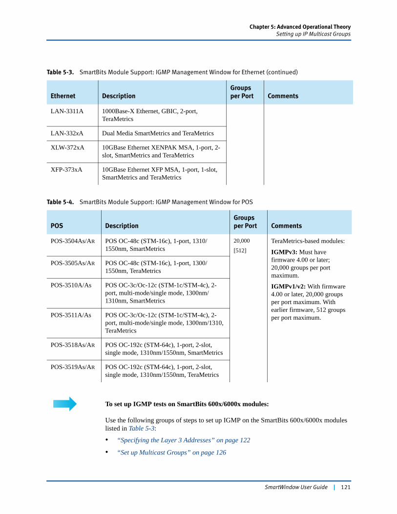
Chapter 5: Advanced Operational TheorySetting up IP Multicast Groups
To set up IGMP tests on SmartBits 600x/6000x modules:
Use the following groups of steps to set up IGMP on the SmartBits 600x/6000x modules listed in Table 5-3:
• “Specifying the Layer 3 Addresses” on page 122
• “Set up Multicast Groups” on page 126
LAN-3311A 1000Base-X Ethernet, GBIC, 2-port, TeraMetrics
LAN-332xA Dual Media SmartMetrics and TeraMetrics
XLW-372xA 10GBase Ethernet XENPAK MSA, 1-port, 2-slot, SmartMetrics and TeraMetrics
XFP-373xA 10GBase Ethernet XFP MSA, 1-port, 1-slot, SmartMetrics and TeraMetrics
Table 5-4. SmartBits Module Support: IGMP Management Window for POS
POS DescriptionGroups per Port Comments
POS-3504As/AR POS OC-48c (STM-16c), 1-port, 1310/1550nm, SmartMetrics
20,000
[512]TeraMetrics-based modules:
IGMPv3: Must have firmware 4.00 or later; 20,000 groups per port maximum.
IGMPv1/v2: With firmware 4.00 or later, 20,000 groups per port maximum. With earlier firmware, 512 groups per port maximum.
POS-3505As/AR POS OC-48c (STM-16c), 1-port, 1300/1550nm, TeraMetrics
POS-3510A/As POS OC-3c/Oc-12c (STM-1c/STM-4c), 2-port, multi-mode/single mode, 1300nm/1310nm, SmartMetrics
POS-3511A/As POS OC-3c/Oc-12c (STM-1c/STM-4c), 2-port, multi-mode/single mode, 1300nm/1310, TeraMetrics
POS-3518As/AR POS OC-192c (STM-64c), 1-port, 2-slot, single mode, 1310nm/1550nm, SmartMetrics
POS-3519As/AR POS OC-192c (STM-64c), 1-port, 2-slot, single mode, 1310nm/1550nm, TeraMetrics
Table 5-3. SmartBits Module Support: IGMP Management Window for Ethernet (continued)
Ethernet DescriptionGroups per Port Comments
SmartWindow User Guide | 121
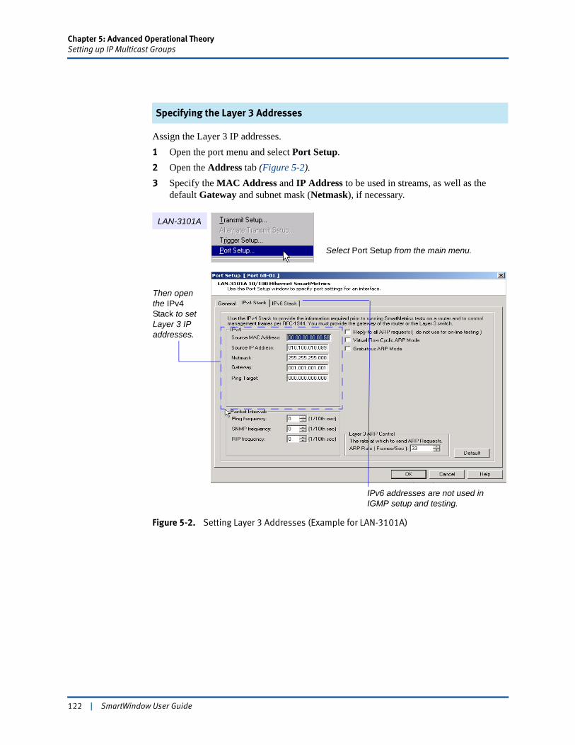
Chapter 5: Advanced Operational TheorySetting up IP Multicast Groups
Specifying the Layer 3 Addresses
Assign the Layer 3 IP addresses.1 Open the port menu and select Port Setup.2 Open the Address tab (Figure 5-2).3 Specify the MAC Address and IP Address to be used in streams, as well as the
default Gateway and subnet mask (Netmask), if necessary.
Figure 5-2. Setting Layer 3 Addresses (Example for LAN-3101A)
Select Port Setup from the main menu.
LAN-3101A
Then open the IPv4 Stack to set Layer 3 IP addresses.
IPv6 addresses are not used in IGMP setup and testing.
122 | SmartWindow User Guide
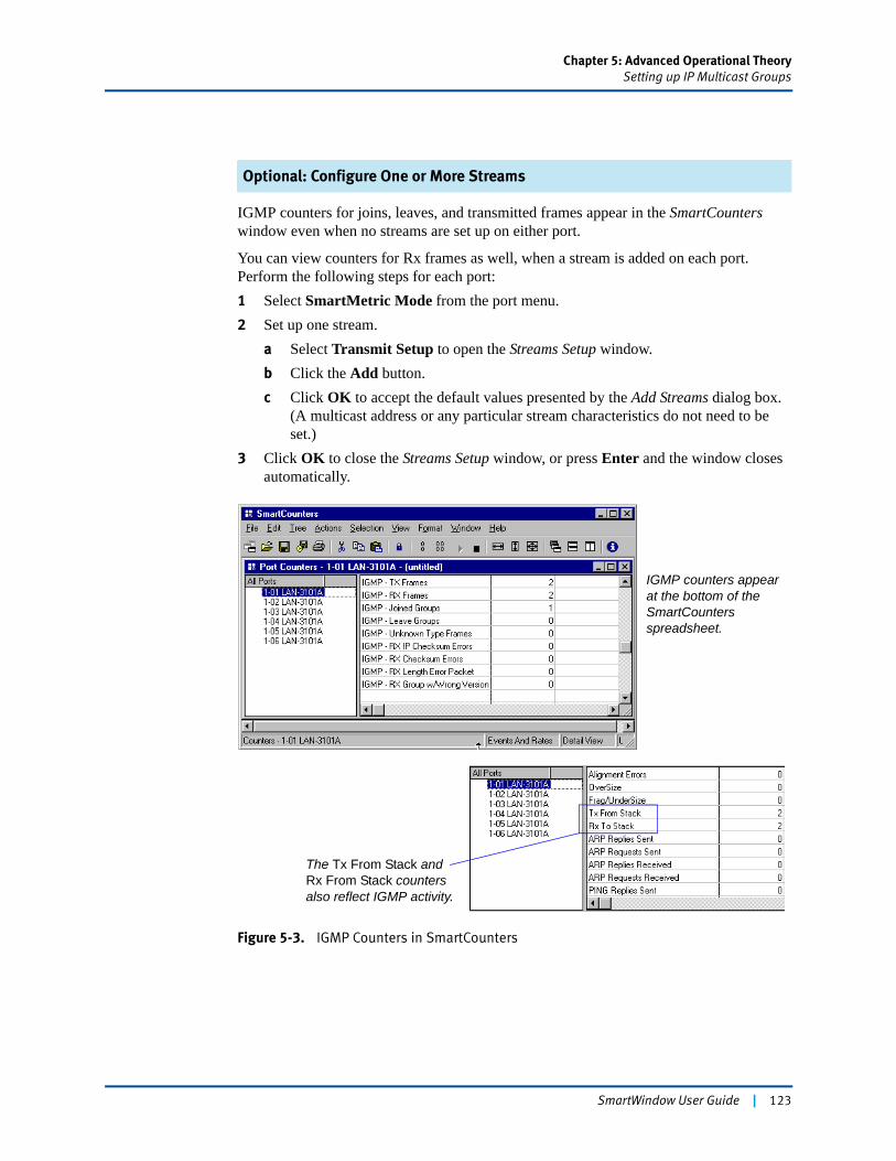
Chapter 5: Advanced Operational TheorySetting up IP Multicast Groups
Optional: Configure One or More Streams
IGMP counters for joins, leaves, and transmitted frames appear in the SmartCounters window even when no streams are set up on either port.
You can view counters for Rx frames as well, when a stream is added on each port. Perform the following steps for each port:1 Select SmartMetric Mode from the port menu.2 Set up one stream.
a Select Transmit Setup to open the Streams Setup window.b Click the Add button.c Click OK to accept the default values presented by the Add Streams dialog box.
(A multicast address or any particular stream characteristics do not need to be set.)
3 Click OK to close the Streams Setup window, or press Enter and the window closes automatically.
Figure 5-3. IGMP Counters in SmartCounters
IGMP counters appear at the bottom of the SmartCounters spreadsheet.
The Tx From Stack and Rx From Stack counters also reflect IGMP activity.
SmartWindow User Guide | 123

Chapter 5: Advanced Operational TheorySetting up IP Multicast Groups
Configure Groups and Port Settings
1 Click the port button of any reserved module and select IGMP Setup.The IGMP Management window opens.
Figure 5-4. IGMP Management Window – SmartBits 600x/60000x Modules
2 Click the Groups button to open the Group Membership Setup dialog box (Figure 5-5 on page 125).The Available Ports list includes all ports on all modules that have been reserved.
3 To set up IGMP group membership on any port:a Select the port.b Use the entry fields to set the desired values for IGMP Version and Group Count.c Click Apply to add the new values for the selected port.
4 Select each available port (in turn) to specify the IGMP settings for that port.
The default values specify IGMP Version 3. On fast Ethernet modules, up to 1,023 groups per port can be added. (See Table 5-1, “SmartBits Cards and Modules Supporting IGMP,” on page 112.) On TeraMetrics modules, up to 20,000 groups can be added.
When IGMP Version 3 is selected (the default), additional options are available. These include Robustness Variable, Report Interval, and Record Suppression.
Important: Be sure to click Apply for each port to add the new values. Clicking OK closes the window but does not save your settings.
124 | SmartWindow User Guide
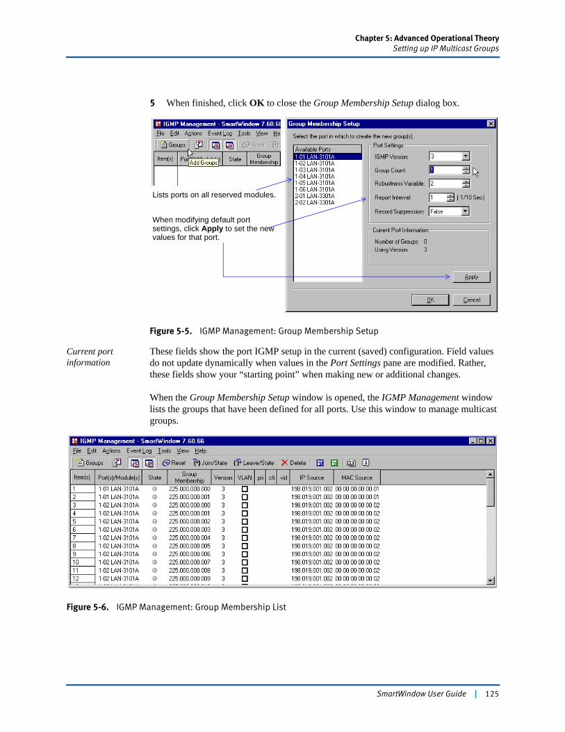
Chapter 5: Advanced Operational TheorySetting up IP Multicast Groups
5 When finished, click OK to close the Group Membership Setup dialog box.
Figure 5-5. IGMP Management: Group Membership Setup
Current port information
These fields show the port IGMP setup in the current (saved) configuration. Field values do not update dynamically when values in the Port Settings pane are modified. Rather, these fields show your “starting point” when making new or additional changes.
When the Group Membership Setup window is opened, the IGMP Management window lists the groups that have been defined for all ports. Use this window to manage multicast groups.
Figure 5-6. IGMP Management: Group Membership List
Lists ports on all reserved modules.
When modifying default port settings, click Apply to set the new values for that port.
SmartWindow User Guide | 125
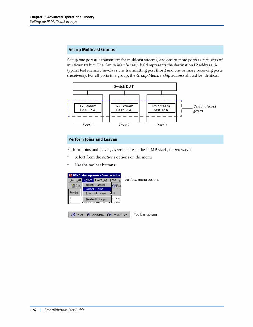
Chapter 5: Advanced Operational TheorySetting up IP Multicast Groups
Set up Multicast Groups
Set up one port as a transmitter for multicast streams, and one or more ports as receivers of multicast traffic. The Group Membership field represents the destination IP address. A typical test scenario involves one transmitting port (host) and one or more receiving ports (receivers). For all ports in a group, the Group Membership address should be identical.
Perform Joins and Leaves
Perform joins and leaves, as well as reset the IGMP stack, in two ways:
• Select from the Actions options on the menu.
• Use the toolbar buttons.
Port 1 Port 2 Port 3
Tx StreamDest IP ADest IP A Dest IP ARx StreamRx Stream One multicast
group
Switch DUT
Actions menu options
Toolbar options
126 | SmartWindow User Guide
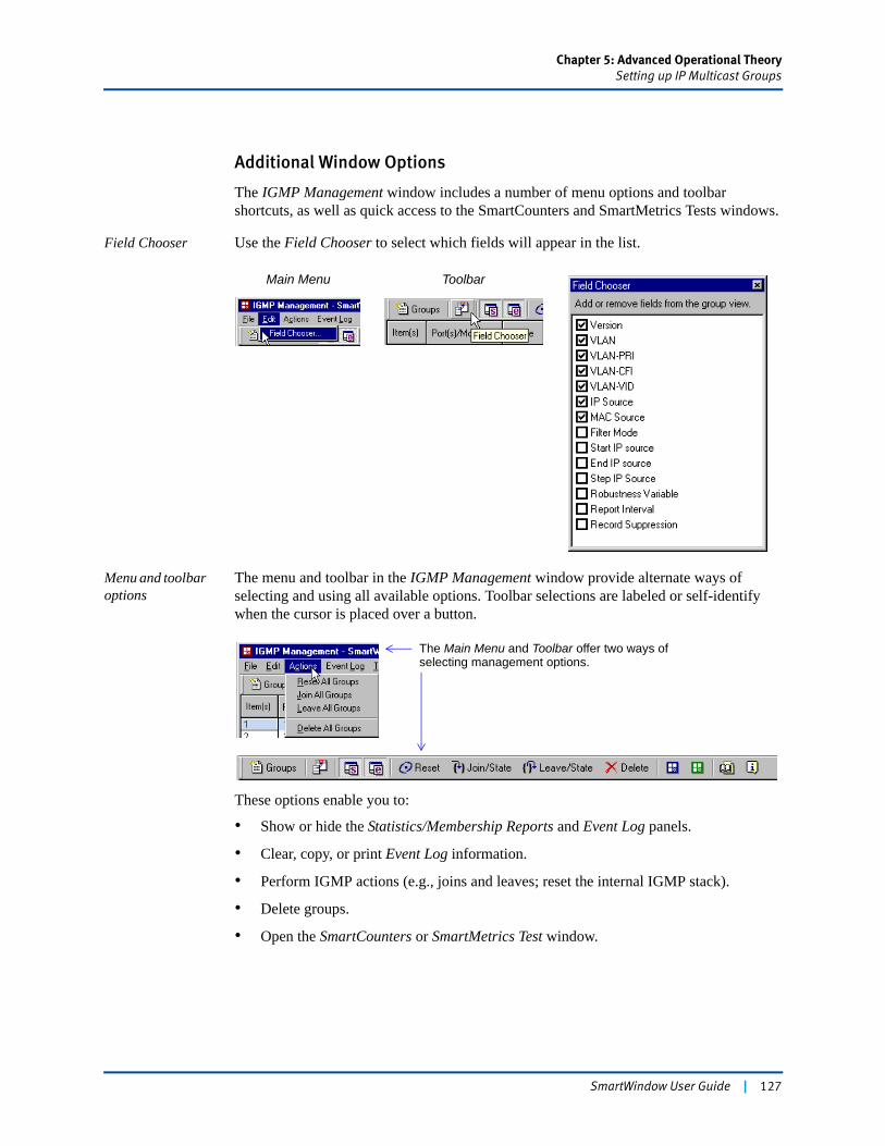
Chapter 5: Advanced Operational TheorySetting up IP Multicast Groups
Additional Window Options
The IGMP Management window includes a number of menu options and toolbar shortcuts, as well as quick access to the SmartCounters and SmartMetrics Tests windows.
Field Chooser Use the Field Chooser to select which fields will appear in the list.
Menu and toolbar options
The menu and toolbar in the IGMP Management window provide alternate ways of selecting and using all available options. Toolbar selections are labeled or self-identify when the cursor is placed over a button.
These options enable you to:
• Show or hide the Statistics/Membership Reports and Event Log panels.
• Clear, copy, or print Event Log information.
• Perform IGMP actions (e.g., joins and leaves; reset the internal IGMP stack).
• Delete groups.
• Open the SmartCounters or SmartMetrics Test window.
Main Menu Toolbar
The Main Menu and Toolbar offer two ways of selecting management options.
SmartWindow User Guide | 127
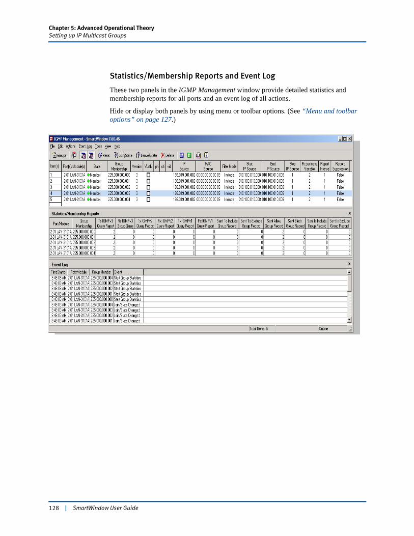
Chapter 5: Advanced Operational TheorySetting up IP Multicast Groups
Statistics/Membership Reports and Event Log
These two panels in the IGMP Management window provide detailed statistics and membership reports for all ports and an event log of all actions.
Hide or display both panels by using menu or toolbar options. (See “Menu and toolbar options” on page 127.)
128 | SmartWindow User Guide
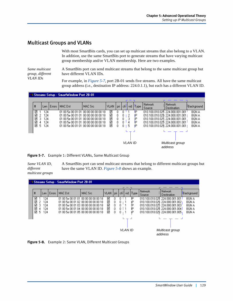
Chapter 5: Advanced Operational TheorySetting up IP Multicast Groups
Multicast Groups and VLANs
With most SmartBits cards, you can set up multicast streams that also belong to a VLAN. In addition, use the same SmartBits port to generate streams that have varying multicast group membership and/or VLAN membership. Here are two examples.
Same multicast group, different VLAN IDs
A SmartBits port can send multicast streams that belong to the same multicast group but have different VLAN IDs.
For example, in Figure 5-7, port 2B-01 sends five streams. All have the same multicast group address (i.e., destination IP address: 224.0.1.1), but each has a different VLAN ID.
Figure 5-7. Example 1: Different VLANs, Same Multicast Group
Same VLAN ID, different multicast groups
A SmartBits port can send multicast streams that belong to different multicast groups but have the same VLAN ID. Figure 5-8 shows an example.
Figure 5-8. Example 2: Same VLAN, Different Multicast Groups
VLAN ID Multicast group address
VLAN ID Multicast group address
SmartWindow User Guide | 129

Chapter 5: Advanced Operational TheorySetting up IP Multicast Groups
VLAN Priority
The VLAN priority field (pri) is used to set one of eight VLAN priorities for each VLAN. These priorities are labelled 0 through 8 and are counted and displayed by priority in the SmartCounters window. This function provides the capability to analyze counts for each VLAN by VLAN priority. The default priority value is zero.
The following modules have this capability.
• LAN-3306A
• LAN-332xA
• XLW-372xA
• XFP-373xA
Review “VLAN Priority Counters” in Chapter 8, “Testing Gigabit Routers,” for a description of how these counters are displayed in the SmartCounters window. Review the Help text for more information on configuring and using VLANs as well as VLAN stacking (QnQ) TX side support features.
130 | SmartWindow User Guide
Chapter 5: Advanced Operational TheorySmartCounters
SmartCountersSmartWindow has two types of SmartCounters with spreadsheet capabilities. Each of these counters is available on one set of modules/cards with a specific hardware chassis. Refer to Table 5-5 for a listing of these combinations and the associated counter title.
This section describes the SmartCounters for cards used on the SmartBits 200/2000 chassis. SmartCounters for modules that use the SmartBits 600x/6000x chassis are primarily described in Chapter 8, “Testing Gigabit Routers.” Other explanations of SmartCounters are given throughout the SmartWindow User Guide and online Help. In such cases, each description is footnoted with the correct reference to the module and chassis.
The SmartCounters feature used for the SmartBits 200/2000 chassis counts the cumulative number of transmit frames and calculates the transmit frame rate. SmartBits 600x/6000x uses a different method in calculating the number of frames.
The SmartBits 600x/6000x counters record the number of frames transmitted in the previous second. The counter is updated once (and only once) per second. It is not cumulative and reports the number of frames transmitted in the previous second. If the counter is polled 50 times a second, the same figure appears 50 times, until the hardware updates the counter with the number of frames transmitted in the previous second (which is reported another 50 times until it is updated again).
SmartCounters for SmartBits 200/2000 Cards
The SmartCounters window offers features available in many traditional spreadsheets. The SmartCounters window displays two statistics for each port:
• Events – The number of occurrences of an action, such as transmitting or receiving a frame, since the last time that counter was reset or cleared.
• Rates – The number of events per second at which the events happen.
Table 5-5. Counter Title
Card/Module Chassis Counter Title
AT-9xxx, GX-1xxx, ML-xxxx, ST-6410, SX-7xxx, and WN-34xx
SmartBits 200/2000 SmartCounters
FBC-360xA, LAN-3xxxA, POS-3xxxA, XLW-372xA, and XFP-373xA
SmartBits 600x/6000x SmartCounters
SmartWindow User Guide | 131
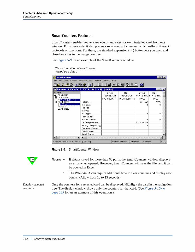
Chapter 5: Advanced Operational TheorySmartCounters
SmartCounters Features
SmartCounters enables you to view events and rates for each installed card from one window. For some cards, it also presents sub-groups of counters, which reflect different protocols or functions. For these, the standard expansion ( + ) button lets you open and close branches in the navigation tree.
See Figure 5-9 for an example of the SmartCounters window.
Figure 5-9. SmartCounter Window
Notes: • If data is saved for more than 68 ports, the SmartCounters window displays an error when opened. However, SmartCounters will save the file, and it can be opened in Excel.
• The WN-3445A can require additional time to clear counters and display new counts. (Allow from 10 to 15 seconds.)
Display selected counters
Only the counters for a selected card can be displayed. Highlight the card in the navigation tree. The display window shows only the counters for that card. (See Figure 5-10 on page 133 for an an example of this operation.)
Click expansion buttons to viewnested tree data .
132 | SmartWindow User Guide
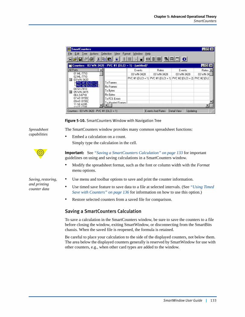
Chapter 5: Advanced Operational TheorySmartCounters
Figure 5-10. SmartCounters Window with Navigation Tree
Spreadsheet capabilities
The SmartCounters window provides many common spreadsheet functions:
• Embed a calculation on a count.Simply type the calculation in the cell.
Important: See “Saving a SmartCounters Calculation” on page 133 for important guidelines on using and saving calculations in a SmartCounters window.
• Modify the spreadsheet format, such as the font or column width with the Format menu options.
Saving, restoring, and printing counter data
• Use menu and toolbar options to save and print the counter information.
• Use timed save feature to save data to a file at selected intervals. (See “Using Timed Save with Counters” on page 136 for information on how to use this option.)
• Restore selected counters from a saved file for comparison.
Saving a SmartCounters Calculation
To save a calculation in the SmartCounters window, be sure to save the counters to a file before closing the window, exiting SmartWindow, or disconnecting from the SmartBits chassis. When the saved file is reopened, the formula is retained.
Be careful to place your calculation to the side of the displayed counters, not below them. The area below the displayed counters generally is reserved by SmartWindow for use with other counters, e.g., when other card types are added to the window.
SmartWindow User Guide | 133
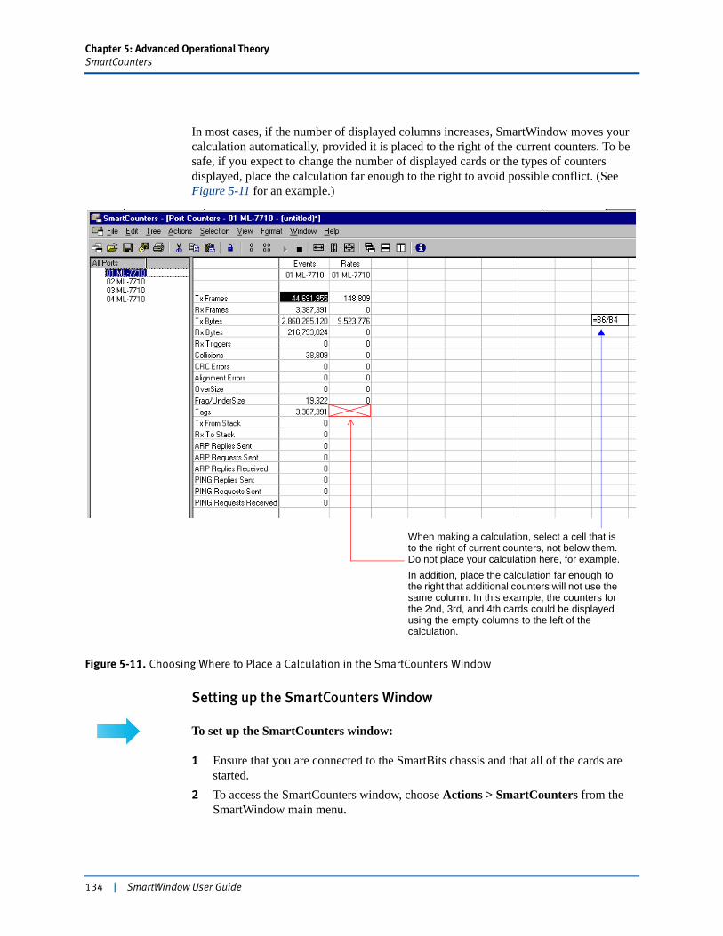
Chapter 5: Advanced Operational TheorySmartCounters
In most cases, if the number of displayed columns increases, SmartWindow moves your calculation automatically, provided it is placed to the right of the current counters. To be safe, if you expect to change the number of displayed cards or the types of counters displayed, place the calculation far enough to the right to avoid possible conflict. (See Figure 5-11 for an example.)
Figure 5-11. Choosing Where to Place a Calculation in the SmartCounters Window
Setting up the SmartCounters Window
To set up the SmartCounters window:
1 Ensure that you are connected to the SmartBits chassis and that all of the cards are started.
2 To access the SmartCounters window, choose Actions > SmartCounters from the SmartWindow main menu.
When making a calculation, select a cell that is to the right of current counters, not below them. Do not place your calculation here, for example.In addition, place the calculation far enough to the right that additional counters will not use the same column. In this example, the counters for the 2nd, 3rd, and 4th cards could be displayed using the empty columns to the left of the calculation.
134 | SmartWindow User Guide
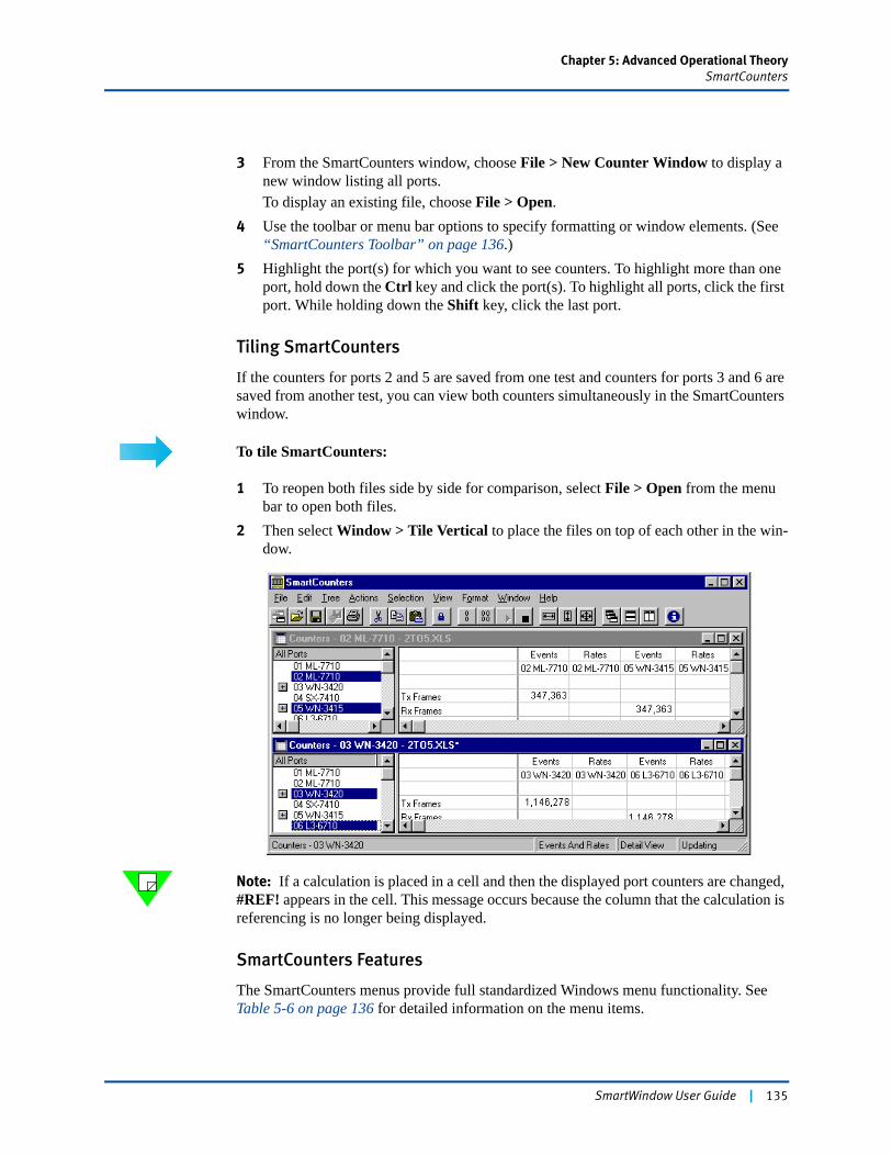
Chapter 5: Advanced Operational TheorySmartCounters
3 From the SmartCounters window, choose File > New Counter Window to display a new window listing all ports.To display an existing file, choose File > Open.
4 Use the toolbar or menu bar options to specify formatting or window elements. (See “SmartCounters Toolbar” on page 136.)
5 Highlight the port(s) for which you want to see counters. To highlight more than one port, hold down the Ctrl key and click the port(s). To highlight all ports, click the first port. While holding down the Shift key, click the last port.
Tiling SmartCounters
If the counters for ports 2 and 5 are saved from one test and counters for ports 3 and 6 are saved from another test, you can view both counters simultaneously in the SmartCounters window.
To tile SmartCounters:
1 To reopen both files side by side for comparison, select File > Open from the menu bar to open both files.
2 Then select Window > Tile Vertical to place the files on top of each other in the win-dow.
Note: If a calculation is placed in a cell and then the displayed port counters are changed, #REF! appears in the cell. This message occurs because the column that the calculation is referencing is no longer being displayed.
SmartCounters Features
The SmartCounters menus provide full standardized Windows menu functionality. See Table 5-6 on page 136 for detailed information on the menu items.
SmartWindow User Guide | 135
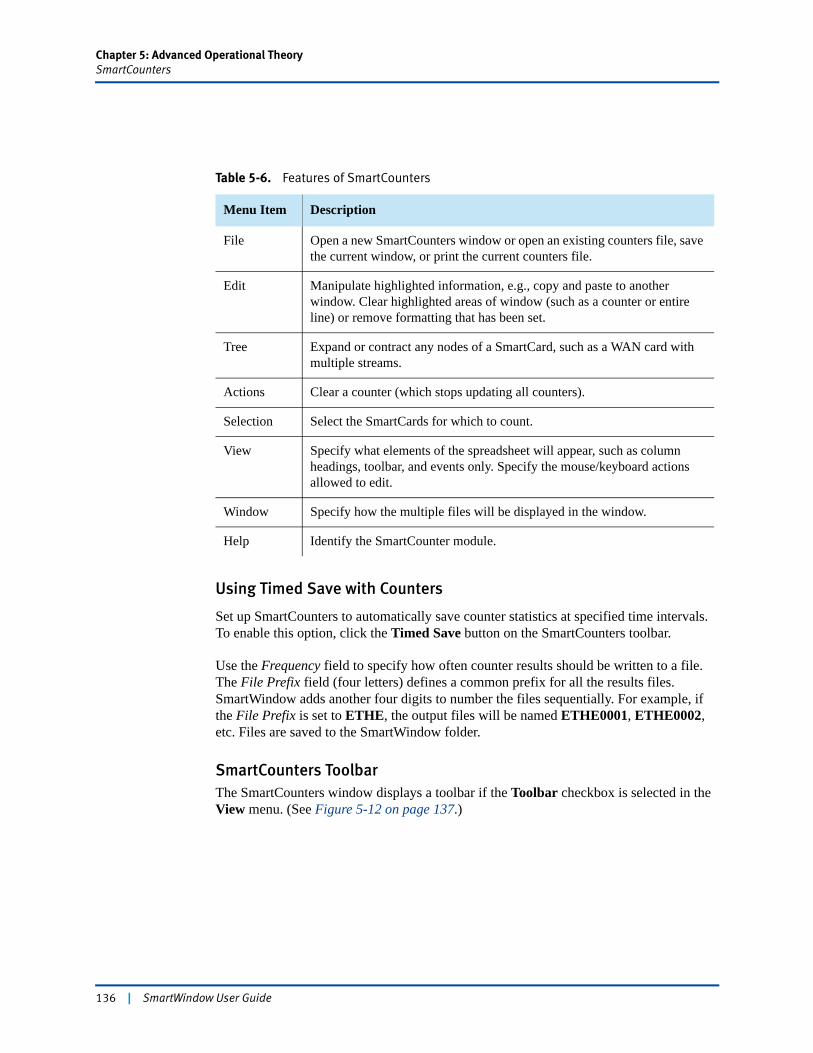
Chapter 5: Advanced Operational TheorySmartCounters
Using Timed Save with Counters
Set up SmartCounters to automatically save counter statistics at specified time intervals. To enable this option, click the Timed Save button on the SmartCounters toolbar.
Use the Frequency field to specify how often counter results should be written to a file. The File Prefix field (four letters) defines a common prefix for all the results files. SmartWindow adds another four digits to number the files sequentially. For example, if the File Prefix is set to ETHE, the output files will be named ETHE0001, ETHE0002, etc. Files are saved to the SmartWindow folder.
SmartCounters ToolbarThe SmartCounters window displays a toolbar if the Toolbar checkbox is selected in the View menu. (See Figure 5-12 on page 137.)
Table 5-6. Features of SmartCounters
Menu Item Description
File Open a new SmartCounters window or open an existing counters file, save the current window, or print the current counters file.
Edit Manipulate highlighted information, e.g., copy and paste to another window. Clear highlighted areas of window (such as a counter or entire line) or remove formatting that has been set.
Tree Expand or contract any nodes of a SmartCard, such as a WAN card with multiple streams.
Actions Clear a counter (which stops updating all counters).
Selection Select the SmartCards for which to count.
View Specify what elements of the spreadsheet will appear, such as column headings, toolbar, and events only. Specify the mouse/keyboard actions allowed to edit.
Window Specify how the multiple files will be displayed in the window.
Help Identify the SmartCounter module.
136 | SmartWindow User Guide
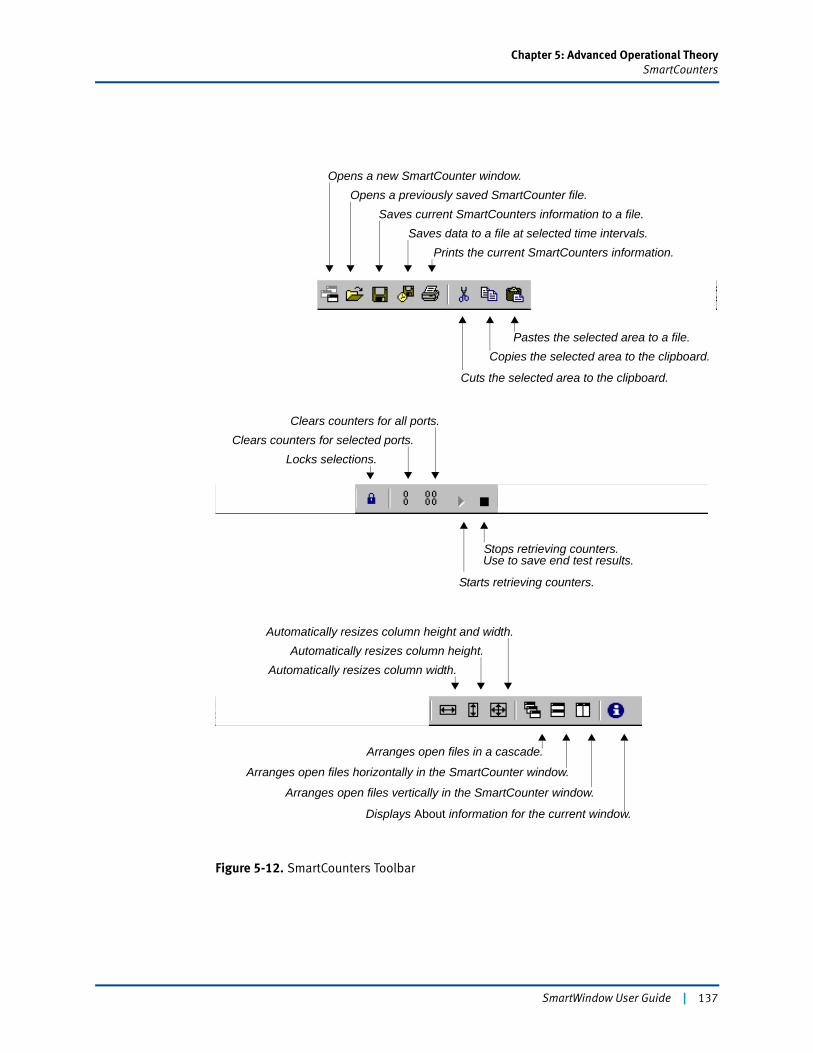
Chapter 5: Advanced Operational TheorySmartCounters
Figure 5-12. SmartCounters Toolbar
Opens a new SmartCounter window.Opens a previously saved SmartCounter file.
Saves current SmartCounters information to a file.Saves data to a file at selected time intervals.
Prints the current SmartCounters information.
Cuts the selected area to the clipboard.
Copies the selected area to the clipboard.Pastes the selected area to a file.
Clears counters for all ports.Clears counters for selected ports.
Locks selections.
Starts retrieving counters.
Automatically resizes column height and width.Automatically resizes column height.
Automatically resizes column width.
Displays About information for the current window.
Arranges open files vertically in the SmartCounter window.
Arranges open files horizontally in the SmartCounter window.
Arranges open files in a cascade.
Stops retrieving counters.Use to save end test results.
SmartWindow User Guide | 137
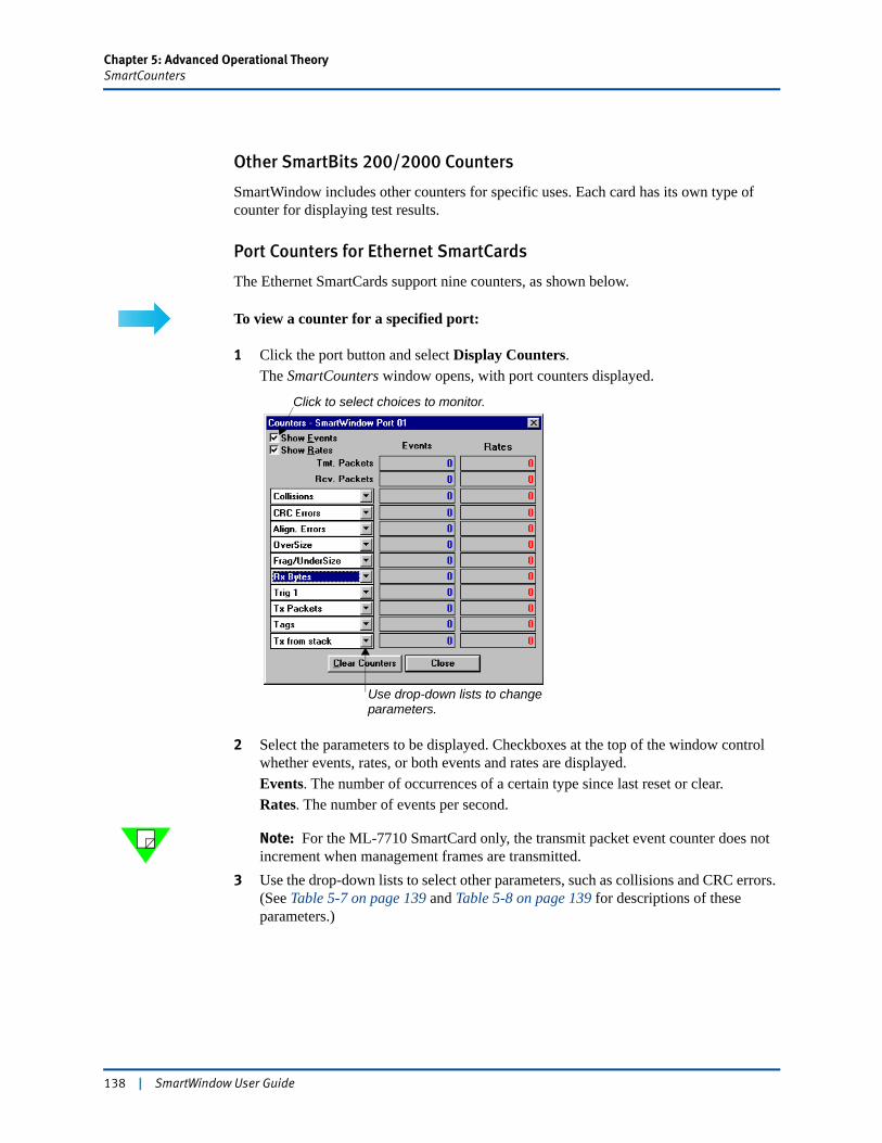
Chapter 5: Advanced Operational TheorySmartCounters
Other SmartBits 200/2000 Counters
SmartWindow includes other counters for specific uses. Each card has its own type of counter for displaying test results.
Port Counters for Ethernet SmartCards
The Ethernet SmartCards support nine counters, as shown below.
To view a counter for a specified port:
1 Click the port button and select Display Counters.The SmartCounters window opens, with port counters displayed.
2 Select the parameters to be displayed. Checkboxes at the top of the window control whether events, rates, or both events and rates are displayed.Events. The number of occurrences of a certain type since last reset or clear.Rates. The number of events per second.
Note: For the ML-7710 SmartCard only, the transmit packet event counter does not increment when management frames are transmitted.
3 Use the drop-down lists to select other parameters, such as collisions and CRC errors. (See Table 5-7 on page 139 and Table 5-8 on page 139 for descriptions of these parameters.)
Click to select choices to monitor.
Use drop-down lists to changeparameters.
138 | SmartWindow User Guide
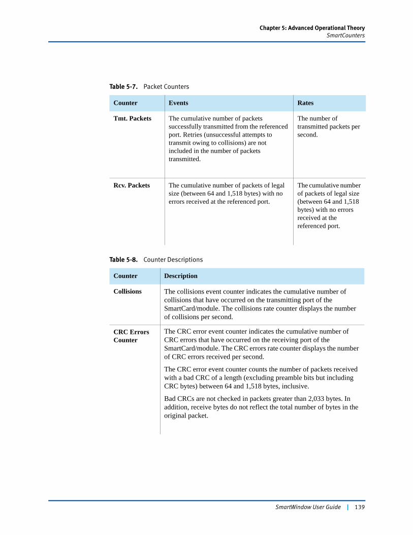
Chapter 5: Advanced Operational TheorySmartCounters
Table 5-7. Packet Counters
Counter Events Rates
Tmt. Packets The cumulative number of packets successfully transmitted from the referenced port. Retries (unsuccessful attempts to transmit owing to collisions) are not included in the number of packets transmitted.
The number of transmitted packets per second.
Rcv. Packets The cumulative number of packets of legal size (between 64 and 1,518 bytes) with no errors received at the referenced port.
The cumulative number of packets of legal size (between 64 and 1,518 bytes) with no errors received at the referenced port.
Table 5-8. Counter Descriptions
Counter Description
Collisions The collisions event counter indicates the cumulative number of collisions that have occurred on the transmitting port of the SmartCard/module. The collisions rate counter displays the number of collisions per second.
CRC Errors Counter
The CRC error event counter indicates the cumulative number of CRC errors that have occurred on the receiving port of the SmartCard/module. The CRC errors rate counter displays the number of CRC errors received per second.
The CRC error event counter counts the number of packets received with a bad CRC of a length (excluding preamble bits but including CRC bytes) between 64 and 1,518 bytes, inclusive.
Bad CRCs are not checked in packets greater than 2,033 bytes. In addition, receive bytes do not reflect the total number of bytes in the original packet.
SmartWindow User Guide | 139
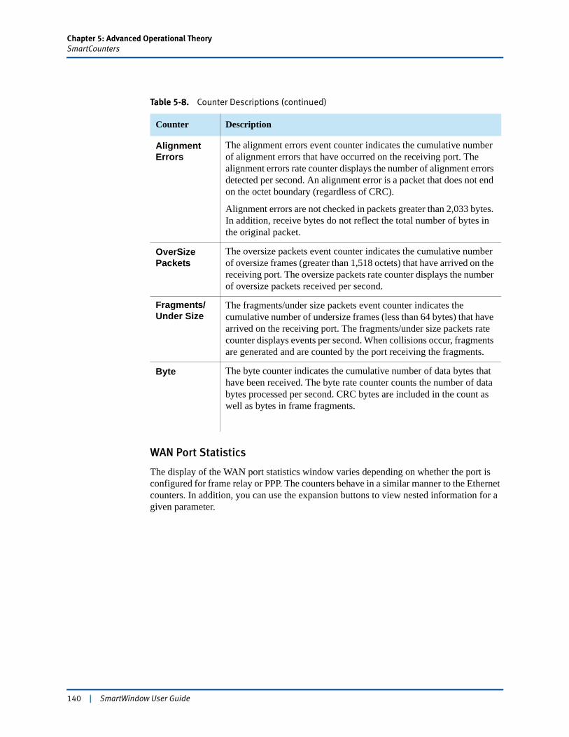
Chapter 5: Advanced Operational TheorySmartCounters
WAN Port Statistics
The display of the WAN port statistics window varies depending on whether the port is configured for frame relay or PPP. The counters behave in a similar manner to the Ethernet counters. In addition, you can use the expansion buttons to view nested information for a given parameter.
Alignment Errors
The alignment errors event counter indicates the cumulative number of alignment errors that have occurred on the receiving port. The alignment errors rate counter displays the number of alignment errors detected per second. An alignment error is a packet that does not end on the octet boundary (regardless of CRC).
Alignment errors are not checked in packets greater than 2,033 bytes. In addition, receive bytes do not reflect the total number of bytes in the original packet.
OverSizePackets
The oversize packets event counter indicates the cumulative number of oversize frames (greater than 1,518 octets) that have arrived on the receiving port. The oversize packets rate counter displays the number of oversize packets received per second.
Fragments/Under Size
The fragments/under size packets event counter indicates the cumulative number of undersize frames (less than 64 bytes) that have arrived on the receiving port. The fragments/under size packets rate counter displays events per second. When collisions occur, fragments are generated and are counted by the port receiving the fragments.
Byte The byte counter indicates the cumulative number of data bytes that have been received. The byte rate counter counts the number of data bytes processed per second. CRC bytes are included in the count as well as bytes in frame fragments.
Table 5-8. Counter Descriptions (continued)
Counter Description
140 | SmartWindow User Guide
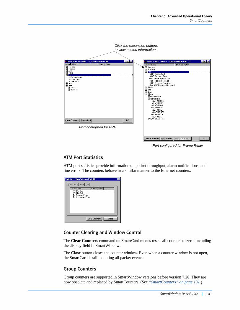
Chapter 5: Advanced Operational TheorySmartCounters
ATM Port Statistics
ATM port statistics provide information on packet throughput, alarm notifications, and line errors. The counters behave in a similar manner to the Ethernet counters.
Counter Clearing and Window Control
The Clear Counters command on SmartCard menus resets all counters to zero, including the display field in SmartWindow.
The Close button closes the counter window. Even when a counter window is not open, the SmartCard is still counting all packet events.
Group Counters
Group counters are supported in SmartWindow versions before version 7.20. They are now obsolete and replaced by SmartCounters. (See “SmartCounters” on page 131.)
Click the expansion buttonsto view nested information.
Port configured for PPP.
Port configured for Frame Relay.
SmartWindow User Guide | 141
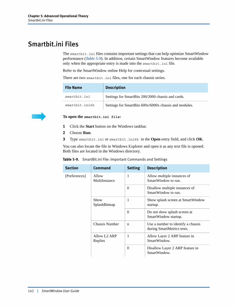
Chapter 5: Advanced Operational TheorySmartbit.ini Files
Smartbit.ini FilesThe smartbit.ini files contains important settings that can help optimize SmartWindow performance (Table 5-9). In addition, certain SmartWindow features become available only when the appropriate entry is made into the smartbit.ini file.
Refer to the SmartWindow online Help for contextual settings.
There are two smartbit.ini files, one for each chassis series.
To open the smartbit.ini file:
1 Click the Start button on the Windows taskbar.2 Choose Run.3 Type smartbit.ini or smartbit.ini6k in the Open entry field, and click OK.
You can also locate the file in Windows Explorer and open it as any text file is opened. Both files are located in the Windows directory.
File Name Description
smartbit.ini Settings for SmartBits 200/2000 chassis and cards.
smartbit.ini6k Settings for SmartBits 600x/6000x chassis and modules.
Table 5-9. SmartBit.ini File: Important Commands and Settings
Section Command Setting Description
[Preferences] Allow MultiInstance
1 Allow multiple instances of SmartWindow to run.
0 Disallow multiple instances of SmartWindow to run.
Show SplashBitmap
1 Show splash screen at SmartWindow startup.
0 Do not show splash screen at SmartWindow startup.
Chassis Number n Use a number to identify a chassis during SmartMetrics tests.
Allow L2 ARP Replies
1 Allow Layer 2 ARP feature in SmartWindow.
0 Disallow Layer 2 ARP feature in SmartWindow.
142 | SmartWindow User Guide

Chapter 5: Advanced Operational TheorySmartbit.ini Files
[Preferences](continued)
Startup Connect 1 Try to connect to a SmartBits at SmartWindow startup.
0 Do not try to connect to a SmartBits at SmartWindow startup.
L3 Signature Control
1 Display Signature field column with checkbox for ML-5710/A, ML-6705, ML-6710, and ML-7710 SmartMetrics VTE Setup windows.
0 Do not display Signature field column with checkbox for ML-5710/A,ML-6705, ML-6710, and ML-7710 SmartMetrics VTE Setup windows.
Initialize on connect
1 Update SmartBits as soon as it is connected.
0 Do not update SmartBits as soon as it is connected.
ML-7710 Can Echo
1 Allow ML-7710 to echo.
0 Disallow ML-7710 to echo.
ML-7710 Can IGMP
1 Allow IGMP feature for ML-7710.
0 Disallow IGMP feature for ML-7710.
ATM VPI/VCI Hex
1 Display ATM VPI/VCI in hex.
0 Display ATM VPI/VCI in decimal.
Admin 1 Allow admin main menu functions on SmartBits 200/2000 chassis.
0 Do not allow admin main menu functions on SmartBits 200/2000 chassis.
[Layer 3 Tests] Simultaneous Start
1 With SmartMetrics cards, start all Tx cards transmitting simultaneously.
0 With SmartMetrics cards, start Tx cards transmitting one-by-one (default).
Table 5-9. SmartBit.ini File: Important Commands and Settings (continued)
Section Command Setting Description
SmartWindow User Guide | 143
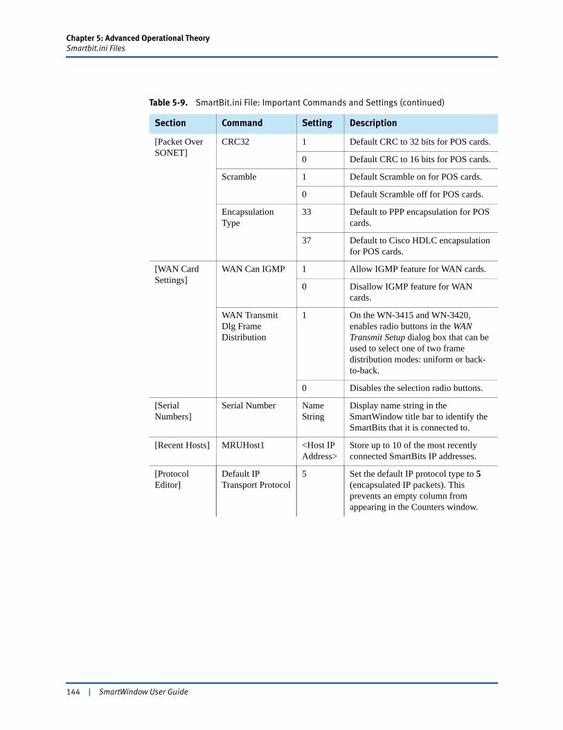
Chapter 5: Advanced Operational TheorySmartbit.ini Files
[Packet Over SONET]
CRC32 1 Default CRC to 32 bits for POS cards.
0 Default CRC to 16 bits for POS cards.
Scramble 1 Default Scramble on for POS cards.
0 Default Scramble off for POS cards.
Encapsulation Type
33 Default to PPP encapsulation for POS cards.
37 Default to Cisco HDLC encapsulation for POS cards.
[WAN Card Settings]
WAN Can IGMP 1 Allow IGMP feature for WAN cards.
0 Disallow IGMP feature for WAN cards.
WAN Transmit Dlg Frame Distribution
1 On the WN-3415 and WN-3420, enables radio buttons in the WAN Transmit Setup dialog box that can be used to select one of two frame distribution modes: uniform or back-to-back.
0 Disables the selection radio buttons.
[Serial Numbers]
Serial Number Name String
Display name string in the SmartWindow title bar to identify the SmartBits that it is connected to.
[Recent Hosts] MRUHost1 <Host IP Address>
Store up to 10 of the most recently connected SmartBits IP addresses.
[Protocol Editor]
Default IP Transport Protocol
5 Set the default IP protocol type to 5 (encapsulated IP packets). This prevents an empty column from appearing in the Counters window.
Table 5-9. SmartBit.ini File: Important Commands and Settings (continued)
Section Command Setting Description
144 | SmartWindow User Guide
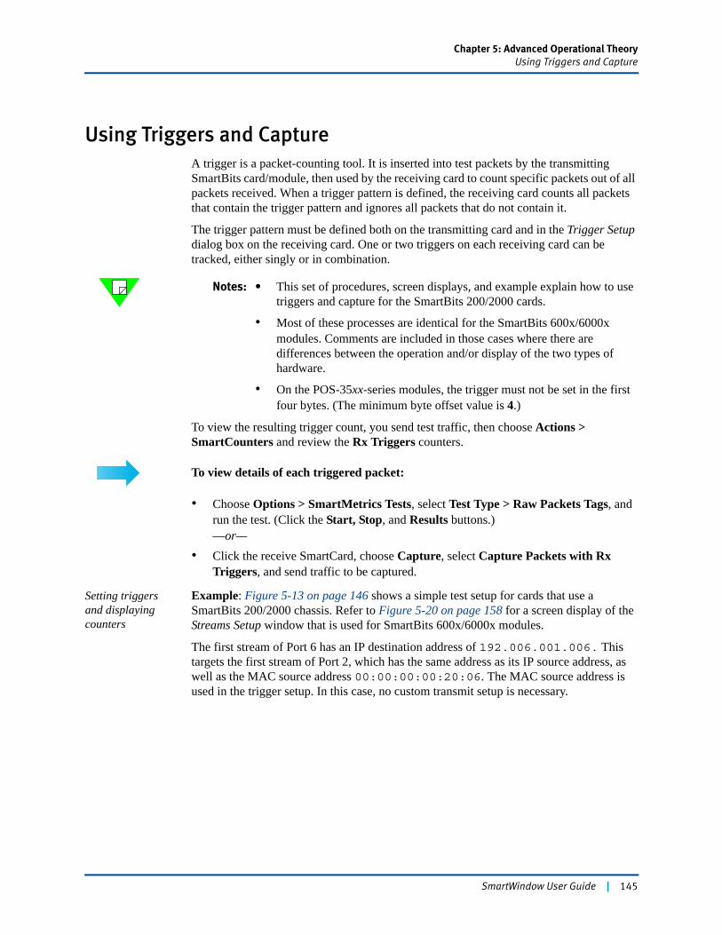
Chapter 5: Advanced Operational TheoryUsing Triggers and Capture
Using Triggers and CaptureA trigger is a packet-counting tool. It is inserted into test packets by the transmitting SmartBits card/module, then used by the receiving card to count specific packets out of all packets received. When a trigger pattern is defined, the receiving card counts all packets that contain the trigger pattern and ignores all packets that do not contain it.
The trigger pattern must be defined both on the transmitting card and in the Trigger Setup dialog box on the receiving card. One or two triggers on each receiving card can be tracked, either singly or in combination.
Notes: • This set of procedures, screen displays, and example explain how to use triggers and capture for the SmartBits 200/2000 cards.
• Most of these processes are identical for the SmartBits 600x/6000x modules. Comments are included in those cases where there are differences between the operation and/or display of the two types of hardware.
• On the POS-35xx-series modules, the trigger must not be set in the first four bytes. (The minimum byte offset value is 4.)
To view the resulting trigger count, you send test traffic, then choose Actions > SmartCounters and review the Rx Triggers counters.
To view details of each triggered packet:
• Choose Options > SmartMetrics Tests, select Test Type > Raw Packets Tags, and run the test. (Click the Start, Stop, and Results buttons.)—or—
• Click the receive SmartCard, choose Capture, select Capture Packets with Rx Triggers, and send traffic to be captured.
Setting triggers and displaying counters
Example: Figure 5-13 on page 146 shows a simple test setup for cards that use a SmartBits 200/2000 chassis. Refer to Figure 5-20 on page 158 for a screen display of the Streams Setup window that is used for SmartBits 600x/6000x modules.
The first stream of Port 6 has an IP destination address of 192.006.001.006. This targets the first stream of Port 2, which has the same address as its IP source address, as well as the MAC source address 00:00:00:00:20:06. The MAC source address is used in the trigger setup. In this case, no custom transmit setup is necessary.
SmartWindow User Guide | 145
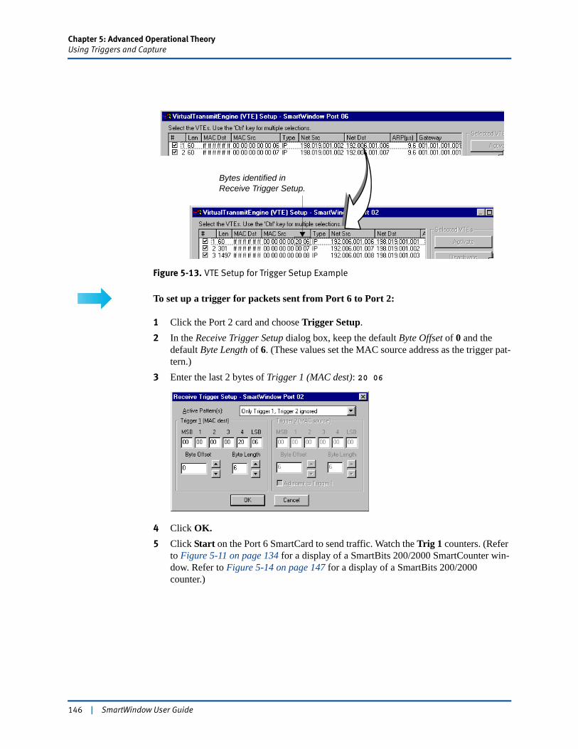
Chapter 5: Advanced Operational TheoryUsing Triggers and Capture
Figure 5-13. VTE Setup for Trigger Setup Example
To set up a trigger for packets sent from Port 6 to Port 2:
1 Click the Port 2 card and choose Trigger Setup.2 In the Receive Trigger Setup dialog box, keep the default Byte Offset of 0 and the
default Byte Length of 6. (These values set the MAC source address as the trigger pat-tern.)
3 Enter the last 2 bytes of Trigger 1 (MAC dest): 20 06
4 Click OK.5 Click Start on the Port 6 SmartCard to send traffic. Watch the Trig 1 counters. (Refer
to Figure 5-11 on page 134 for a display of a SmartBits 200/2000 SmartCounter win-dow. Refer to Figure 5-14 on page 147 for a display of a SmartBits 200/2000 counter.)
Bytes identified in Receive Trigger Setup.
146 | SmartWindow User Guide
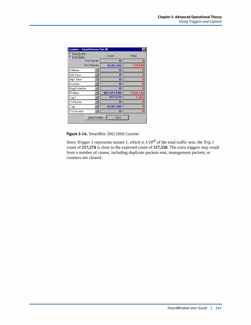
Chapter 5: Advanced Operational TheoryUsing Triggers and Capture
Figure 5-14. SmartBits 200/2000 Counter
Since Trigger 1 represents stream 1, which is 1/20th of the total traffic sent, the Trig 1 count of 517,574 is close to the expected count of 517,558. The extra triggers may result from a number of causes, including duplicate packets sent, management packets, or counters not cleared.
SmartWindow User Guide | 147
Chapter 5: Advanced Operational TheoryUsing Triggers and Capture
Capturing Packets
Captured test data is displayed in two types of windows: Classic and Decoder. The Classic capture window contains two window panes to allow for viewing of multiple streams and a detailed view of one stream. The Decoder capture window contains three window panes that show multiple streams; selected decoded streams; and hex, decoded stream. (Refer to the online Help for a detailed description of the fields displayed in these windows.)
Notes: • These capture window panes and associated capture functions are not available for cards used with the SmartBits 200/2000 units. Also, the captured frames differ in size between fibre channel and Ethernet. For fibre channel, the capture includes the Start of Header (SOH) and the End of Header (EOH). Ethernet does not include these values.
• See “Using the Data Decoder” on page 167 for information on data decoding capabilities available through an optional data decoder such as the Observer.
• The LAN-3100A can perform capture on one port at a time.
The capture function is configured and initiated through the Port menu.
To capture packets (up to a maximum of approximateluy 500 packets) and look at the packet contents:
1 On the transmitting port, set up the desired transmit parameters, such as transmit mode and count, packet length (without FCS), etc.
2 Click the receiving port, and choose Capture from the Card (Port) menu. (See Figure 5-15 on page 149.)
148 | SmartWindow User Guide
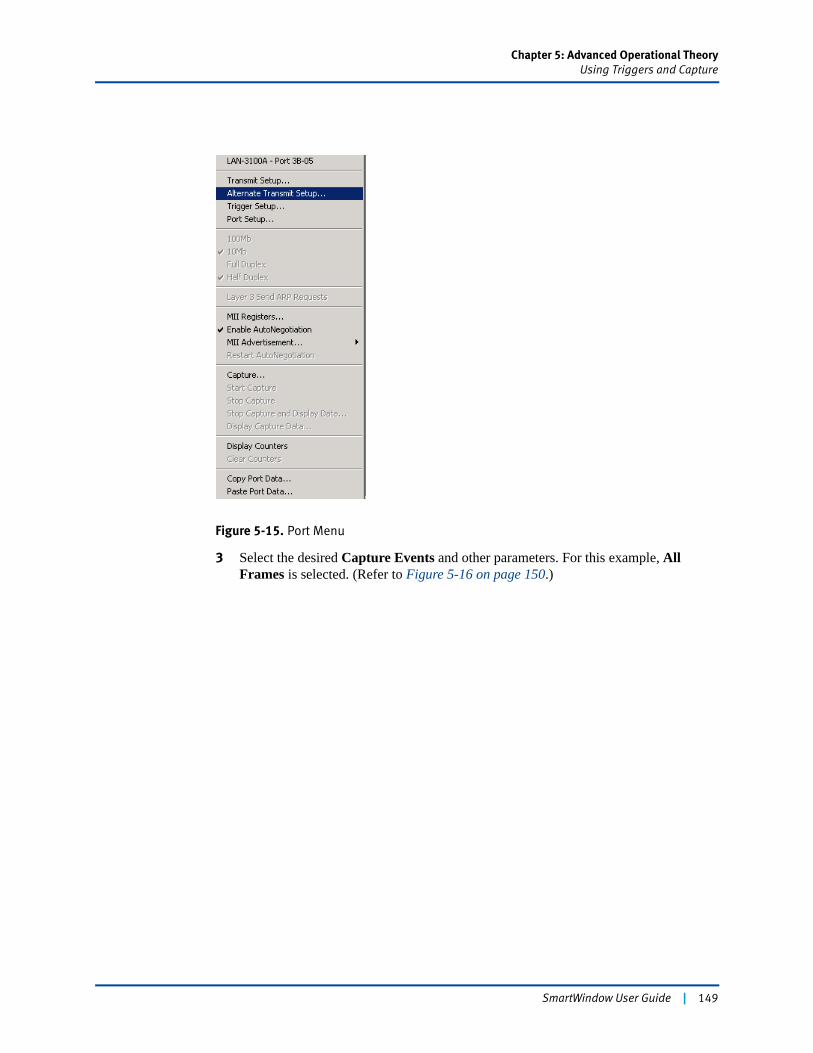
Chapter 5: Advanced Operational TheoryUsing Triggers and Capture
Figure 5-15. Port Menu
3 Select the desired Capture Events and other parameters. For this example, All Frames is selected. (Refer to Figure 5-16 on page 150.)
SmartWindow User Guide | 149

Chapter 5: Advanced Operational TheoryUsing Triggers and Capture
Figure 5-16. Capture Setup window
4 Start the capture on the receiving port. Do this in one of two ways:• Select Start Capture from the Port menu.• Select Capture from the Port menu and then select Actions/Start from the
SmartCapture window. 5 Click the Start button on the transmitting port to begin sending test frames to the
receiving card.6 Select Display Capture Data on the Port menu, or access the SmartCapture win-
dow and select View to view the test stream(s). (Figure 5-17 on page 151 shows the SmartCapture window filling with the results.)The bottom of this window shows the time meter increasing as the test data is dis-played. Adjacent to the time meter is a Cancel button that can be used to terminate the display at a particular point in time.
150 | SmartWindow User Guide
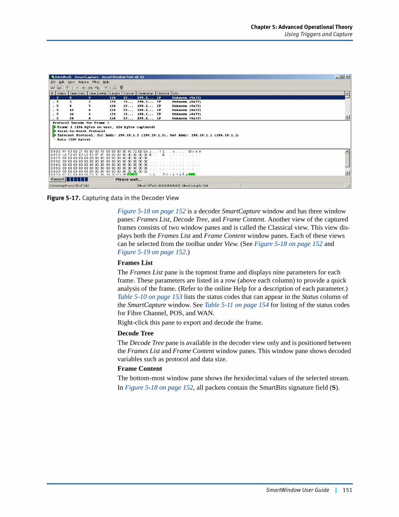
Chapter 5: Advanced Operational TheoryUsing Triggers and Capture
Figure 5-17. Capturing data in the Decoder View
Figure 5-18 on page 152 is a decoder SmartCapture window and has three window panes: Frames List, Decode Tree, and Frame Content. Another view of the captured frames consists of two window panes and is called the Classical view. This view dis-plays both the Frames List and Frame Content window panes. Each of these views can be selected from the toolbar under View. (See Figure 5-18 on page 152 and Figure 5-19 on page 152.)Frames ListThe Frames List pane is the topmost frame and displays nine parameters for each frame. These parameters are listed in a row (above each column) to provide a quick analysis of the frame. (Refer to the online Help for a description of each parameter.) Table 5-10 on page 153 lists the status codes that can appear in the Status column of the SmartCapture window. See Table 5-11 on page 154 for listing of the status codes for Fibre Channel, POS, and WAN.Right-click this pane to export and decode the frame.Decode TreeThe Decode Tree pane is available in the decoder view only and is positioned between the Frames List and Frame Content window panes. This window pane shows decoded variables such as protocol and data size.Frame Content The bottom-most window pane shows the hexidecimal values of the selected stream.In Figure 5-18 on page 152, all packets contain the SmartBits signature field (S).
SmartWindow User Guide | 151
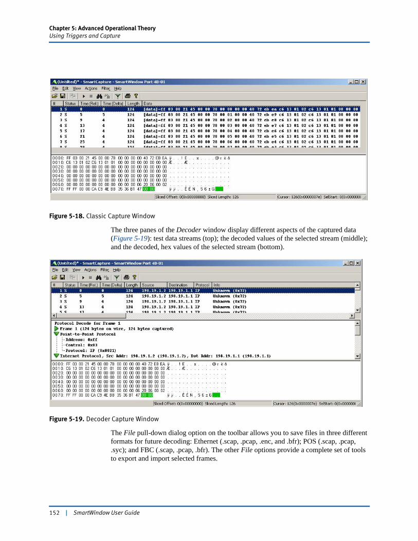
Chapter 5: Advanced Operational TheoryUsing Triggers and Capture
Figure 5-18. Classic Capture Window
The three panes of the Decoder window display different aspects of the captured data (Figure 5-19): test data streams (top); the decoded values of the selected stream (middle); and the decoded, hex values of the selected stream (bottom).
Figure 5-19. Decoder Capture Window
The File pull-down dialog option on the toolbar allows you to save files in three different formats for future decoding: Ethernet (.scap, .pcap, .enc, and .bfr); POS (.scap, .pcap, .syc); and FBC (.scap, .pcap, .bfr). The other File options provide a complete set of tools to export and import selected frames.
152 | SmartWindow User Guide
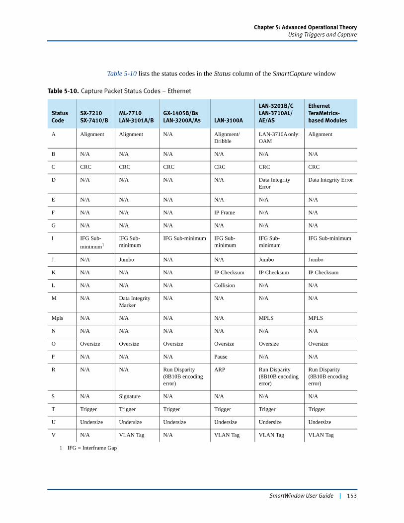
Chapter 5: Advanced Operational TheoryUsing Triggers and Capture
Table 5-10 lists the status codes in the Status column of the SmartCapture window
Table 5-10. Capture Packet Status Codes – Ethernet
Status Code
SX-7210SX-7410/B
ML-7710LAN-3101A/B
GX-1405B/BsLAN-3200A/AS LAN-3100A
LAN-3201B/CLAN-3710AL/AE/AS
Ethernet TeraMetrics-based Modules
A Alignment Alignment N/A Alignment/Dribble
LAN-3710A only: OAM
Alignment
B N/A N/A N/A N/A N/A N/A
C CRC CRC CRC CRC CRC CRC
D N/A N/A N/A N/A Data Integrity Error
Data Integrity Error
E N/A N/A N/A N/A N/A N/A
F N/A N/A N/A IP Frame N/A N/A
G N/A N/A N/A N/A N/A N/A
I IFG Sub-minimum1
1 IFG = Interframe Gap
IFG Sub-minimum
IFG Sub-minimum IFG Sub-minimum
IFG Sub-minimum
IFG Sub-minimum
J N/A Jumbo N/A N/A Jumbo Jumbo
K N/A N/A N/A IP Checksum IP Checksum IP Checksum
L N/A N/A N/A Collision N/A N/A
M N/A Data Integrity Marker
N/A N/A N/A N/A
Mpls N/A N/A N/A N/A MPLS MPLS
N N/A N/A N/A N/A N/A N/A
O Oversize Oversize Oversize Oversize Oversize Oversize
P N/A N/A N/A Pause N/A N/A
R N/A N/A Run Disparity(8B10B encoding error)
ARP Run Disparity(8B10B encoding error)
Run Disparity(8B10B encoding error)
S N/A Signature N/A N/A N/A N/A
T Trigger Trigger Trigger Trigger Trigger Trigger
U Undersize Undersize Undersize Undersize Undersize Undersize
V N/A VLAN Tag N/A VLAN Tag VLAN Tag VLAN Tag
SmartWindow User Guide | 153
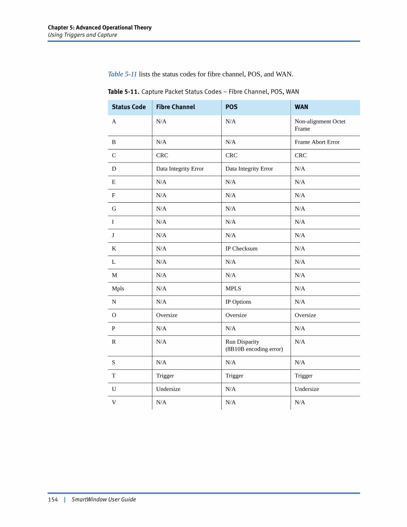
Chapter 5: Advanced Operational TheoryUsing Triggers and Capture
Table 5-11 lists the status codes for fibre channel, POS, and WAN.
Table 5-11. Capture Packet Status Codes – Fibre Channel, POS, WAN
Status Code Fibre Channel POS WAN
A N/A N/A Non-alignment Octet Frame
B N/A N/A Frame Abort Error
C CRC CRC CRC
D Data Integrity Error Data Integrity Error N/A
E N/A N/A N/A
F N/A N/A N/A
G N/A N/A N/A
I N/A N/A N/A
J N/A N/A N/A
K N/A IP Checksum N/A
L N/A N/A N/A
M N/A N/A N/A
Mpls N/A MPLS N/A
N N/A IP Options N/A
O Oversize Oversize Oversize
P N/A N/A N/A
R N/A Run Disparity(8B10B encoding error)
N/A
S N/A N/A N/A
T Trigger Trigger Trigger
U Undersize N/A Undersize
V N/A N/A N/A
154 | SmartWindow User Guide
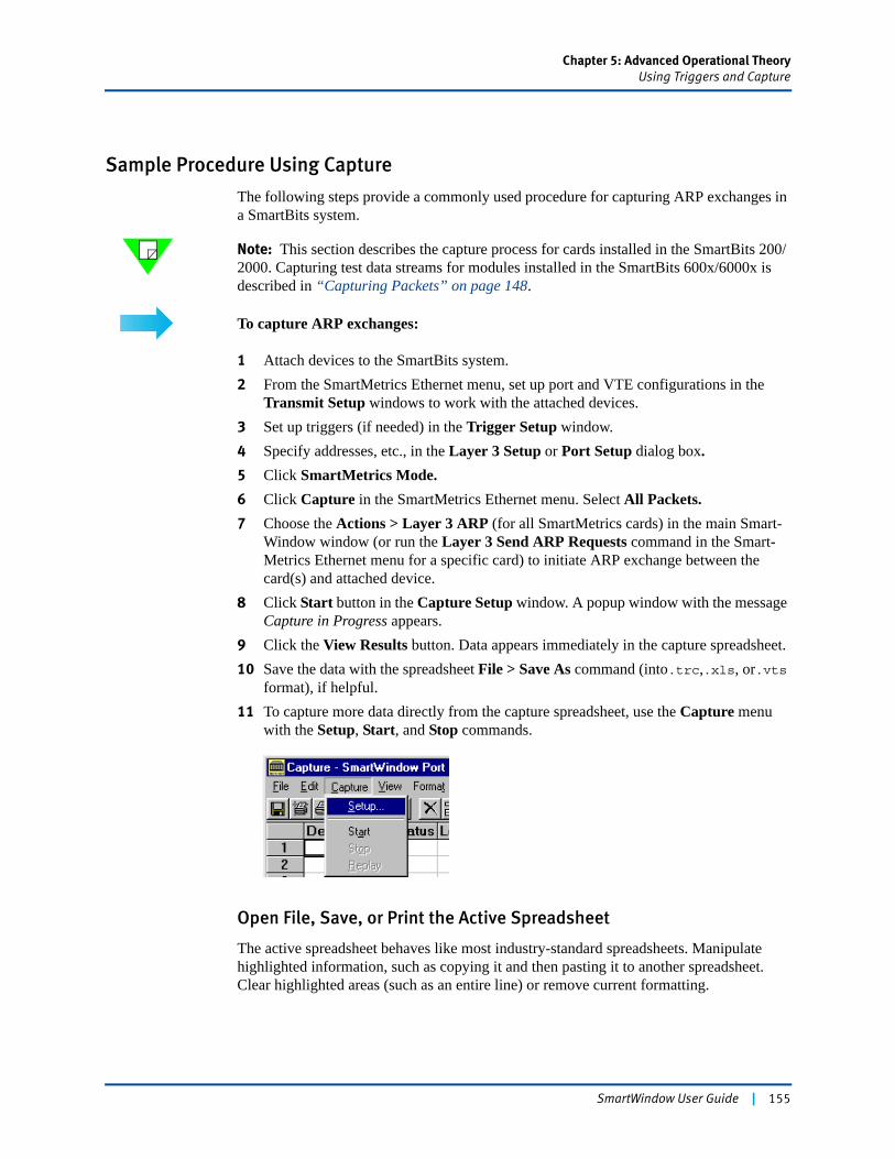
Chapter 5: Advanced Operational TheoryUsing Triggers and Capture
Sample Procedure Using Capture
The following steps provide a commonly used procedure for capturing ARP exchanges in a SmartBits system.
Note: This section describes the capture process for cards installed in the SmartBits 200/2000. Capturing test data streams for modules installed in the SmartBits 600x/6000x is described in “Capturing Packets” on page 148.
To capture ARP exchanges:
1 Attach devices to the SmartBits system.2 From the SmartMetrics Ethernet menu, set up port and VTE configurations in the
Transmit Setup windows to work with the attached devices.3 Set up triggers (if needed) in the Trigger Setup window.4 Specify addresses, etc., in the Layer 3 Setup or Port Setup dialog box.5 Click SmartMetrics Mode.6 Click Capture in the SmartMetrics Ethernet menu. Select All Packets.7 Choose the Actions > Layer 3 ARP (for all SmartMetrics cards) in the main Smart-
Window window (or run the Layer 3 Send ARP Requests command in the Smart-Metrics Ethernet menu for a specific card) to initiate ARP exchange between the card(s) and attached device.
8 Click Start button in the Capture Setup window. A popup window with the message Capture in Progress appears.
9 Click the View Results button. Data appears immediately in the capture spreadsheet.10 Save the data with the spreadsheet File > Save As command (into.trc,.xls, or.vts
format), if helpful. 11 To capture more data directly from the capture spreadsheet, use the Capture menu
with the Setup, Start, and Stop commands.
Open File, Save, or Print the Active Spreadsheet
The active spreadsheet behaves like most industry-standard spreadsheets. Manipulate highlighted information, such as copying it and then pasting it to another spreadsheet. Clear highlighted areas (such as an entire line) or remove current formatting.
SmartWindow User Guide | 155
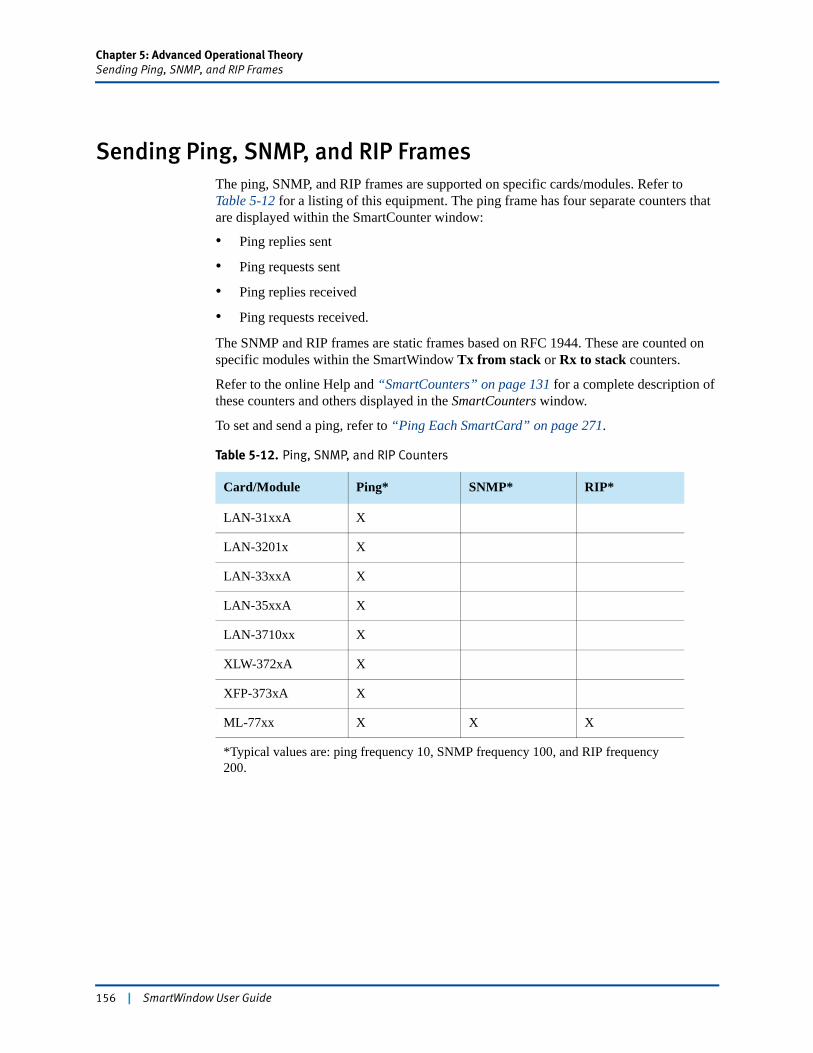
Chapter 5: Advanced Operational TheorySending Ping, SNMP, and RIP Frames
Sending Ping, SNMP, and RIP FramesThe ping, SNMP, and RIP frames are supported on specific cards/modules. Refer to Table 5-12 for a listing of this equipment. The ping frame has four separate counters that are displayed within the SmartCounter window:
• Ping replies sent
• Ping requests sent
• Ping replies received
• Ping requests received.
The SNMP and RIP frames are static frames based on RFC 1944. These are counted on specific modules within the SmartWindow Tx from stack or Rx to stack counters.
Refer to the online Help and “SmartCounters” on page 131 for a complete description of these counters and others displayed in the SmartCounters window.
To set and send a ping, refer to “Ping Each SmartCard” on page 271.
Table 5-12. Ping, SNMP, and RIP Counters
Card/Module Ping* SNMP* RIP*
LAN-31xxA X
LAN-3201x X
LAN-33xxA X
LAN-35xxA X
LAN-3710xx X
XLW-372xA X
XFP-373xA X
ML-77xx X X X
*Typical values are: ping frequency 10, SNMP frequency 100, and RIP frequency 200.
156 | SmartWindow User Guide
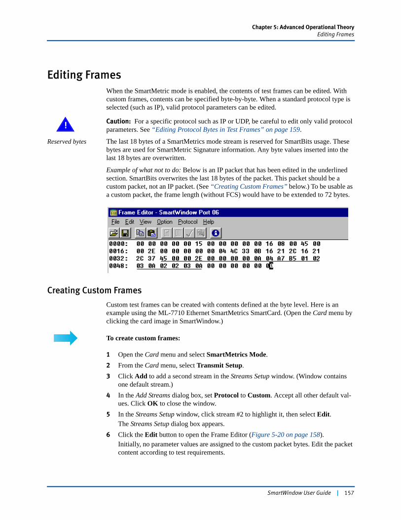
Chapter 5: Advanced Operational TheoryEditing Frames
Editing FramesWhen the SmartMetric mode is enabled, the contents of test frames can be edited. With custom frames, contents can be specified byte-by-byte. When a standard protocol type is selected (such as IP), valid protocol parameters can be edited.
! Caution: For a specific protocol such as IP or UDP, be careful to edit only valid protocol parameters. See “Editing Protocol Bytes in Test Frames” on page 159.
Reserved bytes The last 18 bytes of a SmartMetrics mode stream is reserved for SmartBits usage. These bytes are used for SmartMetric Signature information. Any byte values inserted into the last 18 bytes are overwritten.
Example of what not to do: Below is an IP packet that has been edited in the underlined section. SmartBits overwrites the last 18 bytes of the packet. This packet should be a custom packet, not an IP packet. (See “Creating Custom Frames” below.) To be usable as a custom packet, the frame length (without FCS) would have to be extended to 72 bytes.
Creating Custom Frames
Custom test frames can be created with contents defined at the byte level. Here is an example using the ML-7710 Ethernet SmartMetrics SmartCard. (Open the Card menu by clicking the card image in SmartWindow.)
To create custom frames:
1 Open the Card menu and select SmartMetrics Mode.2 From the Card menu, select Transmit Setup.3 Click Add to add a second stream in the Streams Setup window. (Window contains
one default stream.)4 In the Add Streams dialog box, set Protocol to Custom. Accept all other default val-
ues. Click OK to close the window.5 In the Streams Setup window, click stream #2 to highlight it, then select Edit.
The Streams Setup dialog box appears.6 Click the Edit button to open the Frame Editor (Figure 5-20 on page 158).
Initially, no parameter values are assigned to the custom packet bytes. Edit the packet content according to test requirements.
SmartWindow User Guide | 157
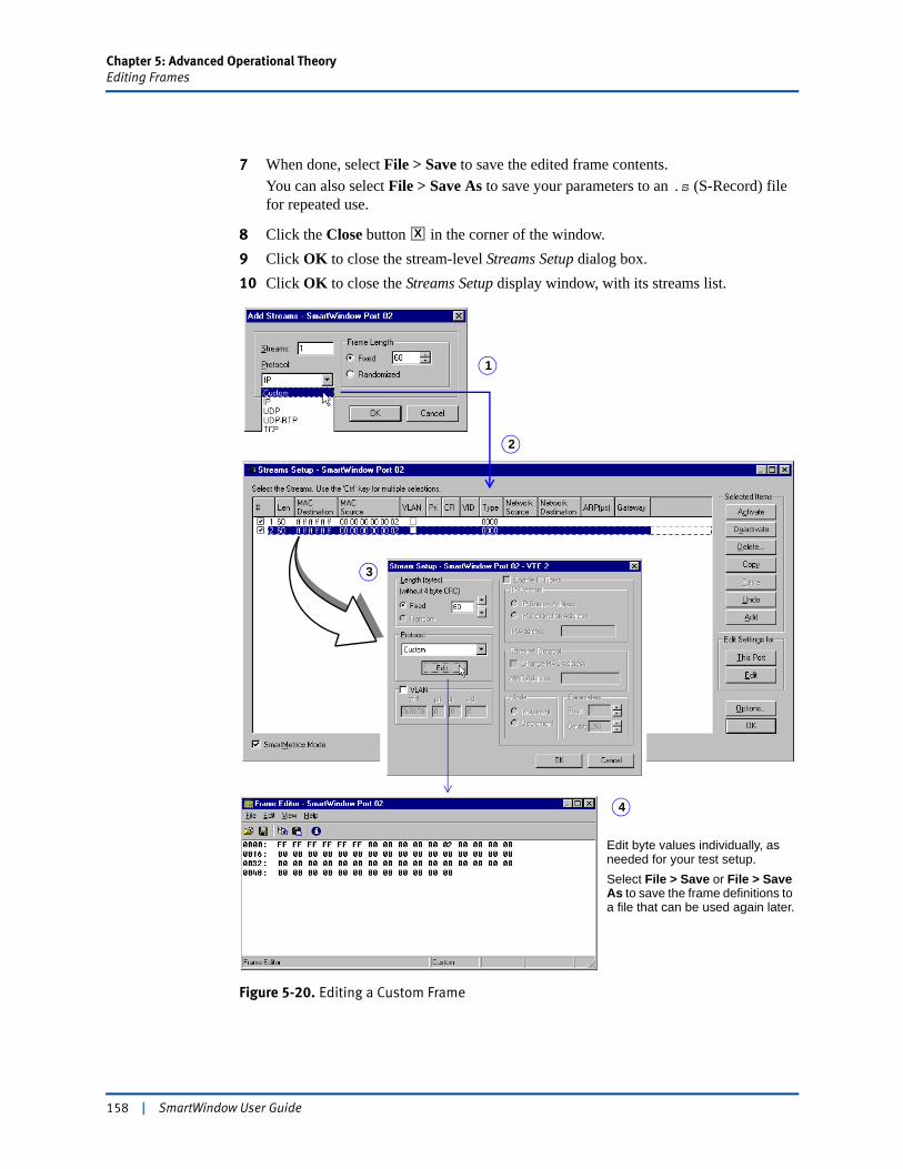
Chapter 5: Advanced Operational TheoryEditing Frames
7 When done, select File > Save to save the edited frame contents.You can also select File > Save As to save your parameters to an .s (S-Record) file for repeated use.
8 Click the Close button in the corner of the window.9 Click OK to close the stream-level Streams Setup dialog box.10 Click OK to close the Streams Setup display window, with its streams list.
Figure 5-20. Editing a Custom Frame
X
1
4
3
2
Edit byte values individually, as needed for your test setup.Select File > Save or File > Save As to save the frame definitions to a file that can be used again later.
158 | SmartWindow User Guide
Chapter 5: Advanced Operational TheoryEditing Frames
Editing Protocol Bytes in Test Frames
When test frames are added based on a standard protocol (such as IP or UDP), selected protocol bytes can be edited.
! Caution: With standard protocols, be careful to edit only valid protocol parameters. Remember that the last 18 bytes of each SmartMetrics mode stream is reserved for Smart-Bits usage. Values inserted into a custom packet in the last 18 bytes are overwritten.
Use the following procedure to edit the protocol bytes in test frames. This example uses the ML-7710 Ethernet SmartMetrics SmartCard. (Open the Card menu by clicking the card image in SmartWindow.)
To edit protocol bytes in test frames:
1 Open the Card menu and select SmartMetrics Mode.2 From the Card menu, select Transmit Setup.3 Click Add to add a second stream in the Streams Setup window. (Window contains
one default stream.)4 In the Add Streams dialog box, accept the default Protocol of IP. Accept all other
default values. Click OK to close the window.5 In the Streams Setup window, click stream #2 to highlight it, then select Edit.
The Streams Setup dialog box appears.6 Click the Edit button to open the Protocol Editor (Figure 5-21 on page 160).7 Double-click in a cell to modify the displayed value.8 When done, select File > Save to save the edited frame contents.
You can also select File > Save As to save the header setup to a .vts (Formula One) file for repeated use.
9 Click the Close button in the corner of the window.10 Click OK to close the stream-level Streams Setup dialog box.
Modified values appear in the stream definition in the Streams Setup display window.
X
SmartWindow User Guide | 159
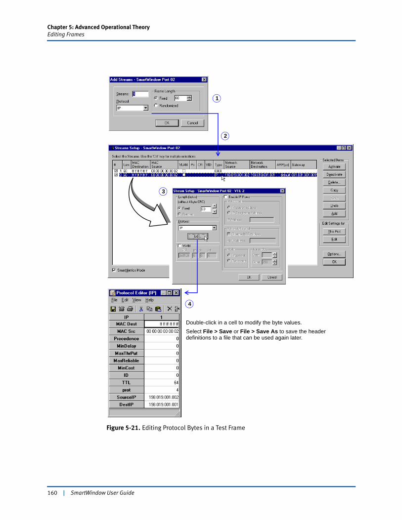
Chapter 5: Advanced Operational TheoryEditing Frames
Figure 5-21. Editing Protocol Bytes in a Test Frame
Double-click in a cell to modify the byte values.Select File > Save or File > Save As to save the header definitions to a file that can be used again later.
1
4
3
2
160 | SmartWindow User Guide
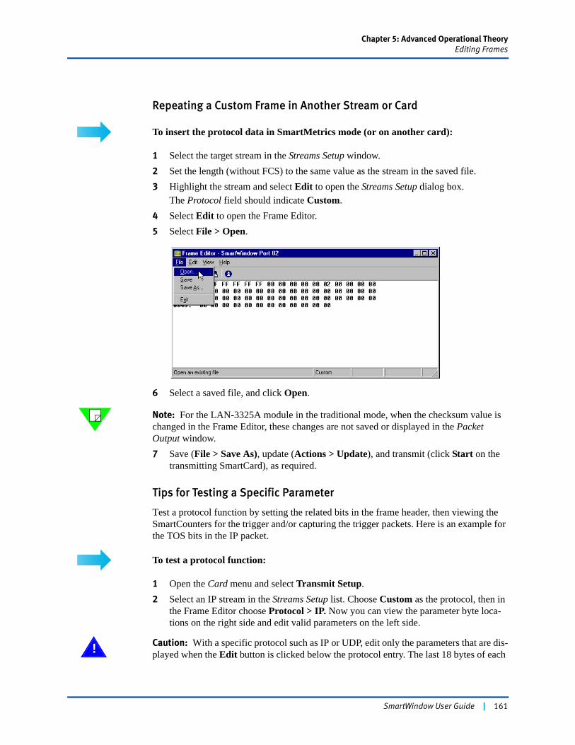
Chapter 5: Advanced Operational TheoryEditing Frames
Repeating a Custom Frame in Another Stream or Card
To insert the protocol data in SmartMetrics mode (or on another card):
1 Select the target stream in the Streams Setup window.2 Set the length (without FCS) to the same value as the stream in the saved file.3 Highlight the stream and select Edit to open the Streams Setup dialog box.
The Protocol field should indicate Custom.4 Select Edit to open the Frame Editor.5 Select File > Open.
6 Select a saved file, and click Open.
Note: For the LAN-3325A module in the traditional mode, when the checksum value is changed in the Frame Editor, these changes are not saved or displayed in the Packet Output window.7 Save (File > Save As), update (Actions > Update), and transmit (click Start on the
transmitting SmartCard), as required.
Tips for Testing a Specific Parameter
Test a protocol function by setting the related bits in the frame header, then viewing the SmartCounters for the trigger and/or capturing the trigger packets. Here is an example for the TOS bits in the IP packet.
To test a protocol function:
1 Open the Card menu and select Transmit Setup.2 Select an IP stream in the Streams Setup list. Choose Custom as the protocol, then in
the Frame Editor choose Protocol > IP. Now you can view the parameter byte loca-tions on the right side and edit valid parameters on the left side.
! Caution: With a specific protocol such as IP or UDP, edit only the parameters that are dis-played when the Edit button is clicked below the protocol entry. The last 18 bytes of each
SmartWindow User Guide | 161
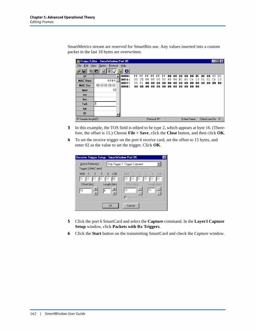
Chapter 5: Advanced Operational TheoryEditing Frames
SmartMetrics stream are reserved for SmartBits use. Any values inserted into a custom packet in the last 18 bytes are overwritten.
3 In this example, the TOS field is edited to be type 2, which appears at byte 16. (There-fore, the offset is 15.) Choose File > Save, click the Close button, and then click OK.
4 To set the receive trigger on the port 6 receive card, set the offset to 15 bytes, and enter 02 as the value to set the trigger. Click OK.
5 Click the port 6 SmartCard and select the Capture command. In the Layer3 Capture Setup window, click Packets with Rx Triggers.
6 Click the Start button on the transmitting SmartCard and check the Capture window.
162 | SmartWindow User Guide
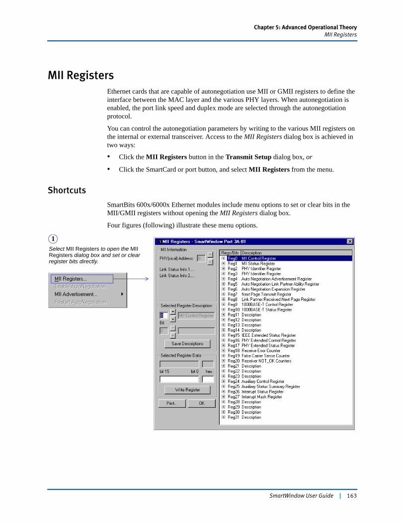
Chapter 5: Advanced Operational TheoryMII Registers
MII RegistersEthernet cards that are capable of autonegotiation use MII or GMII registers to define the interface between the MAC layer and the various PHY layers. When autonegotiation is enabled, the port link speed and duplex mode are selected through the autonegotiation protocol.
You can control the autonegotiation parameters by writing to the various MII registers on the internal or external transceiver. Access to the MII Registers dialog box is achieved in two ways:
• Click the MII Registers button in the Transmit Setup dialog box, or
• Click the SmartCard or port button, and select MII Registers from the menu.
Shortcuts
SmartBits 600x/6000x Ethernet modules include menu options to set or clear bits in the MII/GMII registers without opening the MII Registers dialog box.
Four figures (following) illustrate these menu options.
Select MII Registers to open the MII Registers dialog box and set or clear register bits directly.
1
SmartWindow User Guide | 163
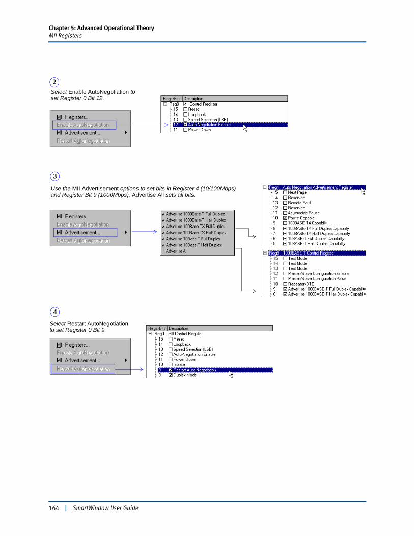
Chapter 5: Advanced Operational TheoryMII Registers
Select Enable AutoNegotiation to set Register 0 Bit 12.
2
Use the MII Advertisement options to set bits in Register 4 (10/100Mbps) and Register Bit 9 (1000Mbps). Advertise All sets all bits.
3
Select Restart AutoNegotiation to set Register 0 Bit 9.
4
164 | SmartWindow User Guide
Chapter 5: Advanced Operational TheoryMII Registers
Enabling Autonegotiation
Although SmartBits recommends testing with port configurations fixed, autonegotiation functions may be required for device testing. For this reason, SmartBits cards and modules support many autonegotiation functions. For device testing of autonegotiation behaviors, use the MII Registers dialog box to set, write, and read port parameters. Testing may also include turning the card autonegotiation option off to expose the behavior of a device when linked ports are mismatched.
Use the MII Registers dialog box to view and modify the 32 MII addresses and registers.
To test autonegotiation without actually enabling autonegotiation:
1 From the SmartWindow menu bar, select Options > Preferences.2 Select the Allow MII Auto-Negotiate checkbox.
Once autonegotiation is selected, speed and duplex selection for individual cards are disabled in the 7x10 Setup menu and SmartCard main menu. However, autonegotiation can be reenabled using the MII registers.
Note: When this option is selected, autonegotiation is enabled globally for all ports on the card; the AN enabled bits are set in the port control registers. These settings always override the control register values saved in a *.prf configuration file. As a result, if you modify the global MII register bit settings, save the configuration file, and disconnect from the chassis, the global settings will take precedence over your file settings the next time that you connect to the chassis and load the configuration file.
Reading and Writing MII Registers
Work with the address/register combinations in the following ways. (See also “Shortcuts” on page 163 for menu options that can be used to set MII register bits.)
Important: You can only write to the MII interface when the SmartBits system is actively connected to the SmartWindow user interface.
• Use the Selected Register Description field to display registers 1 to 31 one at a time. Use the arrow buttons to the right of the corresponding entry field or enter the desired value directly. Addresses 0-31 and registers 0-31 are supported. Click the arrows to the left of the Bit field to view register description.
• Use the Selected Register Data field to view and change bit settings for the selected register. Once you choose a register, the value of the register is displayed in binary and hexadecimal. To write a value to the selected register:
1 Enter the value to be written in either binary (in the binary entry area) or in hexadeci-mal (in the smaller hex entry field).
2 Press the Write Register button. The value is written to the MII register at that time.
SmartWindow User Guide | 165
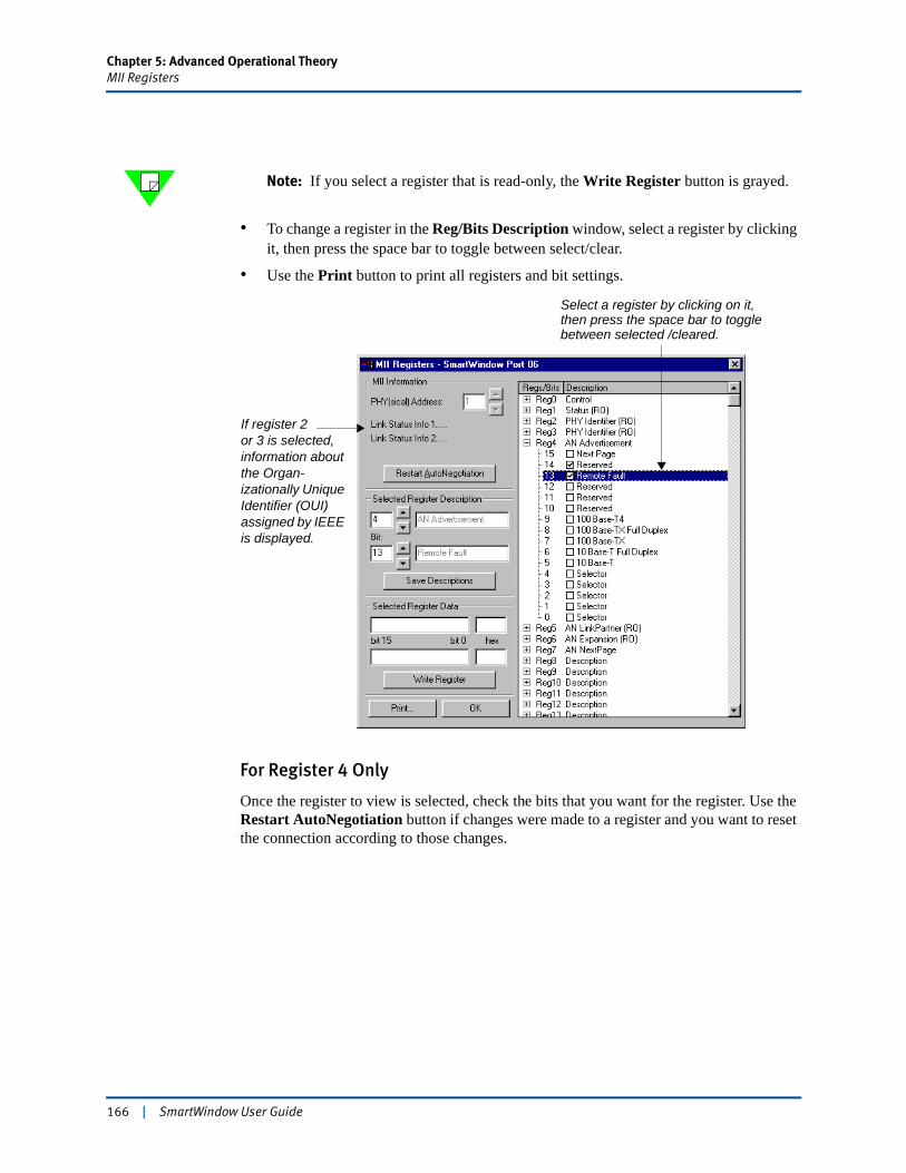
Chapter 5: Advanced Operational TheoryMII Registers
Note: If you select a register that is read-only, the Write Register button is grayed.
• To change a register in the Reg/Bits Description window, select a register by clicking it, then press the space bar to toggle between select/clear.
• Use the Print button to print all registers and bit settings.
For Register 4 Only
Once the register to view is selected, check the bits that you want for the register. Use the Restart AutoNegotiation button if changes were made to a register and you want to reset the connection according to those changes.
If register 2 or 3 is selected, information about the Organ-izationally Unique Identifier (OUI) assigned by IEEE is displayed.
Select a register by clicking on it, then press the space bar to toggle between selected /cleared.
166 | SmartWindow User Guide
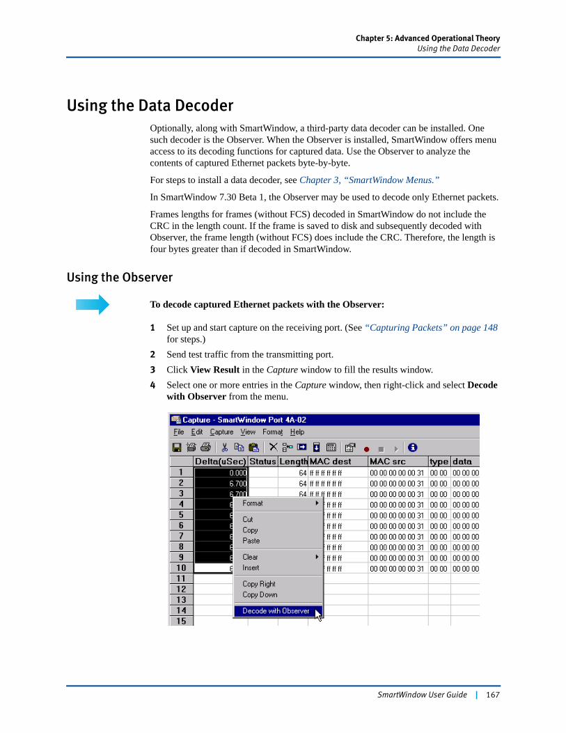
Chapter 5: Advanced Operational TheoryUsing the Data Decoder
Using the Data DecoderOptionally, along with SmartWindow, a third-party data decoder can be installed. One such decoder is the Observer. When the Observer is installed, SmartWindow offers menu access to its decoding functions for captured data. Use the Observer to analyze the contents of captured Ethernet packets byte-by-byte.
For steps to install a data decoder, see Chapter 3, “SmartWindow Menus.”
In SmartWindow 7.30 Beta 1, the Observer may be used to decode only Ethernet packets.
Frames lengths for frames (without FCS) decoded in SmartWindow do not include the CRC in the length count. If the frame is saved to disk and subsequently decoded with Observer, the frame length (without FCS) does include the CRC. Therefore, the length is four bytes greater than if decoded in SmartWindow.
Using the Observer
To decode captured Ethernet packets with the Observer:
1 Set up and start capture on the receiving port. (See “Capturing Packets” on page 148 for steps.)
2 Send test traffic from the transmitting port.3 Click View Result in the Capture window to fill the results window.4 Select one or more entries in the Capture window, then right-click and select Decode
with Observer from the menu.
SmartWindow User Guide | 167
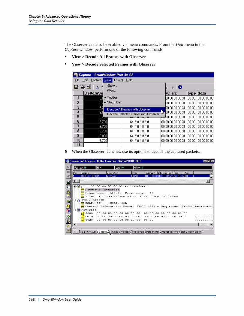
Chapter 5: Advanced Operational TheoryUsing the Data Decoder
The Observer can also be enabled via menu commands. From the View menu in the Capture window, perform one of the following commands:
• View > Decode All Frames with Observer
• View > Decode Selected Frames with Observer
5 When the Observer launches, use its options to decode the captured packets.
168 | SmartWindow User Guide

Chapter 5: Advanced Operational TheoryTesting with IPv6 Streams
Testing with IPv6 StreamsThis section presents guidelines on working with IPv6-based streams. It covers the following topics.
• “SmartBits Module Support for IPv6 Streams” on page 169
• “Frame Header Length” on page 169
• “Selecting an Address Display Format” on page 171
• “IPv6 Header Fields” on page 173
• “Calculating Protocol and Frame Size for IPv6 Streams” on page 175
• “Neighbor Discovery Protocol” on page 179
Note: Refer to “Internet Protocol, Version 6 (IPv6) Specification,” RFC 1883, December 1995 plus related RFCs and specifications for detailed information on IPv6.
SmartBits Module Support for IPv6 Streams
Test with IPv6 streams using the LAN-310xA/B SmartMetrics module and all TeraMetrics-based modules for the SmartBits 6000x family of chassis.
Frame Header LengthAll the IPv6 stream types (IPv6, TCP-IPv6, and UDP-IPv6) require a stream header length of 128 bytes. This ensures that the frame is long enough to include the Signature field, data integrity marker, and other optional fields when enabled.
If required, add the IPv6 stream, using the required 128-byte frame length (without FCS), then reduce the frame length to less than 128. To do this, disable one or more of the optional fields (such as Signature), then adjust the Len value downward. However, remember that SmartMetrics tests depend on the Signature field.
Setting frame header length
Set the header length in the Streams Setup dialog box (Figure 5-22 on page 170). This setting is global; it applies to all streams generated by the port. If you add IPv6 streams, then attempt to reset the Stream Header Length value to 64 bytes, a message warns that this cannot be done. To change the header length value, first delete the IPv6 streams.
Number of Streams
The selected stream header length determines the maximum number of streams for the port. With the 128-byte header required for IPv6 streams, up to 2,048 streams on specific ports can be added. (See Table 5-13 on page 170.) In many cases, this is the same situation in regards to IPv4 streams that use a 64-byte length.
SmartWindow User Guide | 169
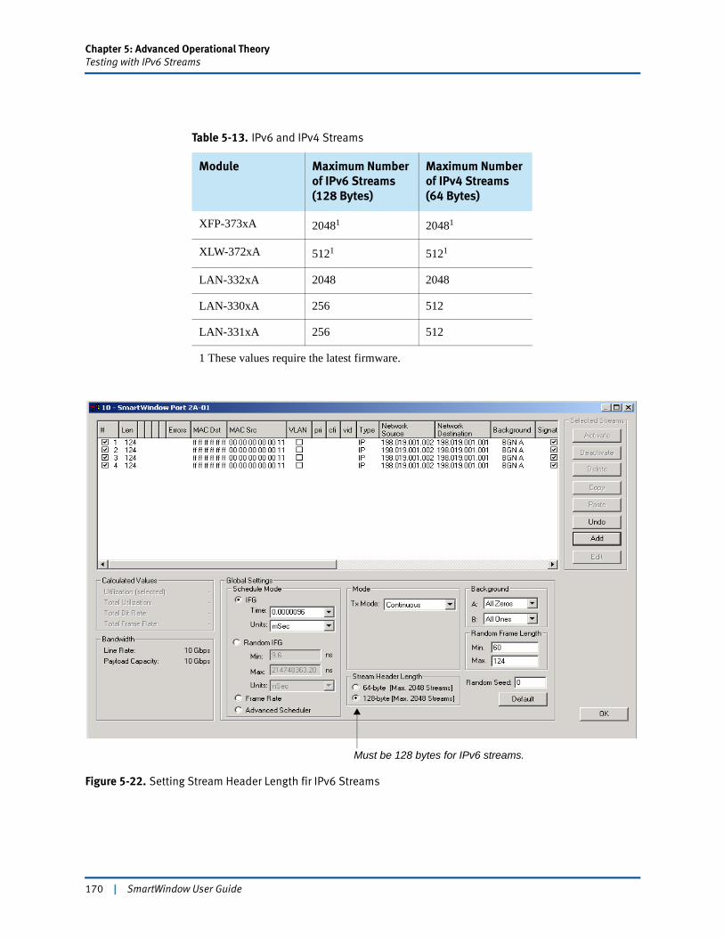
Chapter 5: Advanced Operational TheoryTesting with IPv6 Streams
Figure 5-22. Setting Stream Header Length fir IPv6 Streams
Table 5-13. IPv6 and IPv4 Streams
Module Maximum Number of IPv6 Streams (128 Bytes)
Maximum Number of IPv4 Streams (64 Bytes)
XFP-373xA 20481 20481
XLW-372xA 5121 5121
LAN-332xA 2048 2048
LAN-330xA 256 512
LAN-331xA 256 512
1 These values require the latest firmware.
Must be 128 bytes for IPv6 streams.
170 | SmartWindow User Guide
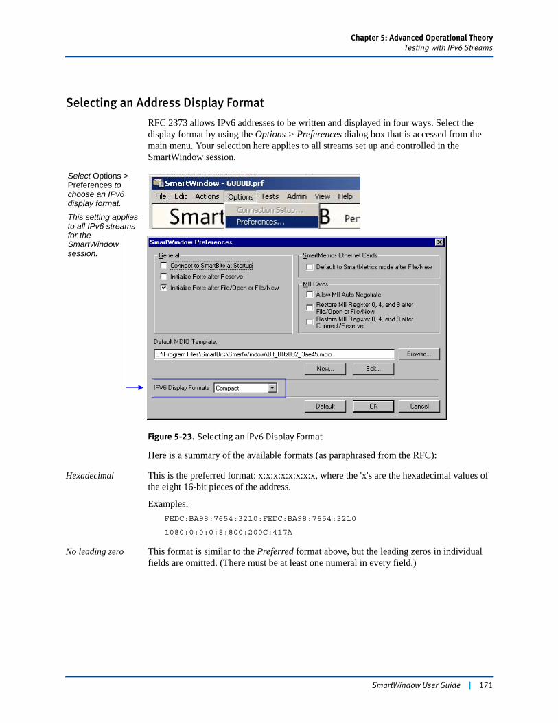
Chapter 5: Advanced Operational TheoryTesting with IPv6 Streams
Selecting an Address Display Format
RFC 2373 allows IPv6 addresses to be written and displayed in four ways. Select the display format by using the Options > Preferences dialog box that is accessed from the main menu. Your selection here applies to all streams set up and controlled in the SmartWindow session.
Figure 5-23. Selecting an IPv6 Display Format
Here is a summary of the available formats (as paraphrased from the RFC):
Hexadecimal This is the preferred format: x:x:x:x:x:x:x:x, where the 'x's are the hexadecimal values of the eight 16-bit pieces of the address.
Examples:FEDC:BA98:7654:3210:FEDC:BA98:7654:3210
1080:0:0:0:8:800:200C:417A
No leading zero This format is similar to the Preferred format above, but the leading zeros in individual fields are omitted. (There must be at least one numeral in every field.)
Select Options > Preferences to choose an IPv6 display format.
This setting applies to all IPv6 streams for the SmartWindow session.
SmartWindow User Guide | 171

Chapter 5: Advanced Operational TheoryTesting with IPv6 Streams
Compact Some methods of allocating IPv6 addresses result in addresses that contain long strings of zero bits. To simplify writing such addresses, a special syntax is available to compress the zeros. The use of "::" indicates multiple groups of 16-bits of zeros. The "::" can only appear once in an address. The "::" can also be used to compress the leading and/or trailing zeros in an address.
Examples:
Unicast address:1080:0:0:0:8:800:200C:417A>1080::8:800:200C:417A
Multicast address:FF01:0:0:0:0:0:0:101> FF01::101
Loopback address:0:0:0:0:0:0:0:1> ::1
Unspecified address:0:0:0:0:0:0:0:0> ::
Mixed This form can be more convenient when dealing with a mixed environment of IPv4 and IPv6 nodes. It is x:x:x:x:x:x:d.d.d.d, where the 'x's are the hexadecimal values of the six high-order 16-bit pieces of the address, and the 'd's are the decimal values of the four low-order 8-bit pieces of the address (standard IPv4 representation).
Examples:0:0:0:0:0:0:13.1.68.3(in compressed form:::13.1.68.3)
0:0:0:0:0:FFFF:129.144.52.38(in compressed form:::FFFF:129.144.52.38)
172 | SmartWindow User Guide
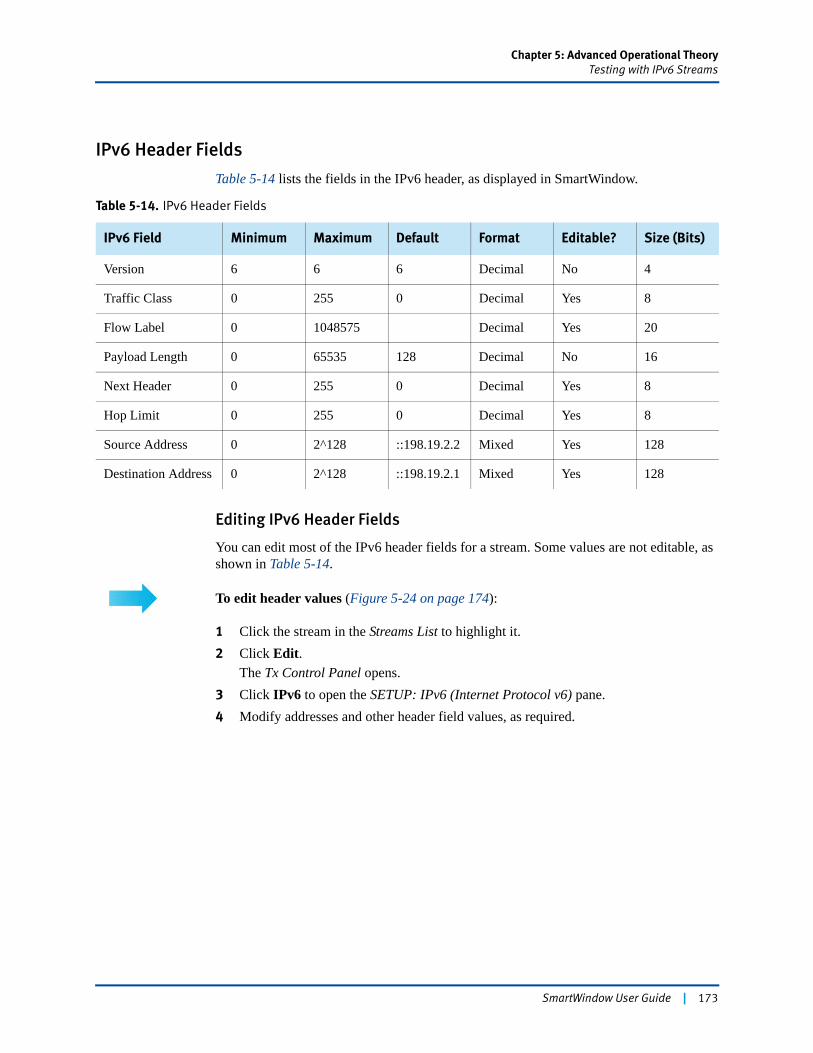
Chapter 5: Advanced Operational TheoryTesting with IPv6 Streams
IPv6 Header Fields
Table 5-14 lists the fields in the IPv6 header, as displayed in SmartWindow.
Editing IPv6 Header Fields
You can edit most of the IPv6 header fields for a stream. Some values are not editable, as shown in Table 5-14.
To edit header values (Figure 5-24 on page 174):
1 Click the stream in the Streams List to highlight it.2 Click Edit.
The Tx Control Panel opens.3 Click IPv6 to open the SETUP: IPv6 (Internet Protocol v6) pane.4 Modify addresses and other header field values, as required.
Table 5-14. IPv6 Header Fields
IPv6 Field Minimum Maximum Default Format Editable? Size (Bits)
Version 6 6 6 Decimal No 4
Traffic Class 0 255 0 Decimal Yes 8
Flow Label 0 1048575 Decimal Yes 20
Payload Length 0 65535 128 Decimal No 16
Next Header 0 255 0 Decimal Yes 8
Hop Limit 0 255 0 Decimal Yes 8
Source Address 0 2^128 ::198.19.2.2 Mixed Yes 128
Destination Address 0 2^128 ::198.19.2.1 Mixed Yes 128
SmartWindow User Guide | 173
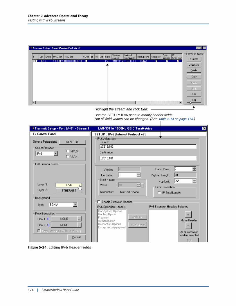
Chapter 5: Advanced Operational TheoryTesting with IPv6 Streams
Figure 5-24. Editing IPv6 Header Fields
Highlight the stream and click Edit.Use the SETUP: IPv6 pane to modify header fields.Not all field values can be changed. (See Table 5-14 on page 173.)
174 | SmartWindow User Guide
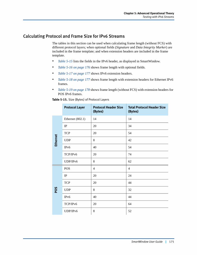
Chapter 5: Advanced Operational TheoryTesting with IPv6 Streams
Calculating Protocol and Frame Size for IPv6 Streams
The tables in this section can be used when calculating frame length (without FCS) with different protocol layers; when optional fields (Signature and Data Integrity Marker) are included in the frame template; and when extension headers are included in the frame template.
• Table 5-15 lists the fields in the IPv6 header, as displayed in SmartWindow.
• Table 5-16 on page 176 shows frame length with optional fields.
• Table 5-17 on page 177 shows IPv6 extension headers.
• Table 5-18 on page 177 shows frame length with extension headers for Ethernet IPv6 frames.
• Table 5-19 on page 178 shows frame length (without FCS) with extension headers for POS IPv6 frames.
Table 5-15. Size (Bytes) of Protocol Layers
Protocol Layer Protocol Header Size (Bytes)
Total Protocol Header Size (Bytes)
Ethe
rnet
Ethernet (802.1) 14 14
IP 20 34
TCP 20 54
UDP 8 42
IPv6 40 54
TCP/IPv6 20 74
UDP/IPv6 8 62
POS
POS 4 4
IP 20 24
TCP 20 44
UDP 8 32
IPv6 40 44
TCP/IPv6 20 64
UDP/IPv6 8 52
SmartWindow User Guide | 175
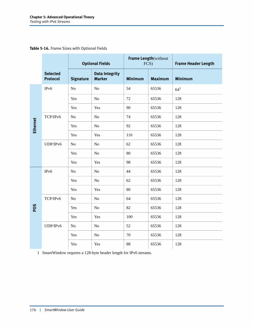
Chapter 5: Advanced Operational TheoryTesting with IPv6 Streams
Table 5-16. Frame Sizes with Optional Fields
Optional FieldsFrame Length(without
FCS) Frame Header Length
Selected Protocol Signature
Data Integrity Marker Minimum Maximum Minimum
Ethe
rnet
IPv6 No No 54 65536 641
Yes No 72 65536 128
Yes Yes 90 65536 128
TCP/IPv6 No No 74 65536 128
Yes No 92 65536 128
Yes Yes 110 65536 128
UDP/IPv6 No No 62 65536 128
Yes No 80 65536 128
Yes Yes 98 65536 128
POS
IPv6 No No 44 65536 128
Yes No 62 65536 128
Yes Yes 80 65536 128
TCP/IPv6 No No 64 65536 128
Yes No 82 65536 128
Yes Yes 100 65536 128
UDP/IPv6 No No 52 65536 128
Yes No 70 65536 128
Yes Yes 88 65536 128
1 SmartWindow requires a 128-byte header length for IPv6 streams.
176 | SmartWindow User Guide
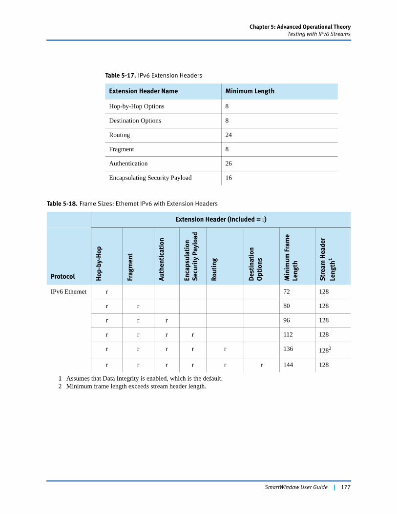
Chapter 5: Advanced Operational TheoryTesting with IPv6 Streams
Table 5-17. IPv6 Extension Headers
Extension Header Name Minimum Length
Hop-by-Hop Options 8
Destination Options 8
Routing 24
Fragment 8
Authentication 26
Encapsulating Security Payload 16
Table 5-18. Frame Sizes: Ethernet IPv6 with Extension Headers
Extension Header (Included = r)
Protocol Hop
-by-
Hop
Frag
men
t
Auth
enti
cati
on
Enca
psul
atio
nS
ecur
ity
Payl
oad
Rout
ing
Des
tina
tion
Opt
ions
Min
imum
Fra
me
Leng
th
Str
eam
Hea
der
Leng
th1
IPv6 Ethernet r 72 128
r r 80 128
r r r 96 128
r r r r 112 128
r r r r r 136 1282
r r r r r r 144 128
1 Assumes that Data Integrity is enabled, which is the default.2 Minimum frame length exceeds stream header length.
SmartWindow User Guide | 177
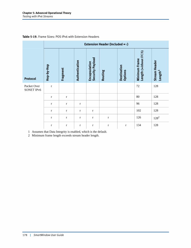
Chapter 5: Advanced Operational TheoryTesting with IPv6 Streams
Table 5-19. Frame Sizes: POS IPv6 with Extension Headers
Extension Header (Included = r)
Protocol Hop
-by-
Hop
Frag
men
t
Auth
enti
cati
on
Enca
psul
atio
nS
ecur
ity
Payl
oad
Rout
ing
Des
tina
tion
Opt
ions
Min
imum
Fra
me
Leng
th (w
ithou
t FC
S)
Str
eam
Hea
der
Leng
th1
Packet Over SONET IPv6
r 72 128
r r 80 128
r r r 96 128
r r r r 102 128
r r r r r 126 1282
r r r r r r 134 128
1 Assumes that Data Integrity is enabled, which is the default.2 Minimum frame length exceeds stream header length.
178 | SmartWindow User Guide
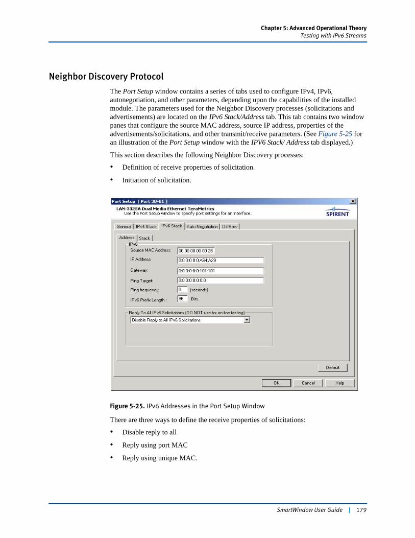
Chapter 5: Advanced Operational TheoryTesting with IPv6 Streams
Neighbor Discovery Protocol
The Port Setup window contains a series of tabs used to configure IPv4, IPv6, autonegotiation, and other parameters, depending upon the capabilities of the installed module. The parameters used for the Neighbor Discovery processes (solicitations and advertisements) are located on the IPv6 Stack/Address tab. This tab contains two window panes that configure the source MAC address, source IP address, properties of the advertisements/solicitations, and other transmit/receive parameters. (See Figure 5-25 for an illustration of the Port Setup window with the IPV6 Stack/ Address tab displayed.)
This section describes the following Neighbor Discovery processes:
• Definition of receive properties of solicitation.
• Initiation of solicitation.
Figure 5-25. IPv6 Addresses in the Port Setup Window
There are three ways to define the receive properties of solicitations:
• Disable reply to all
• Reply using port MAC
• Reply using unique MAC.
SmartWindow User Guide | 179
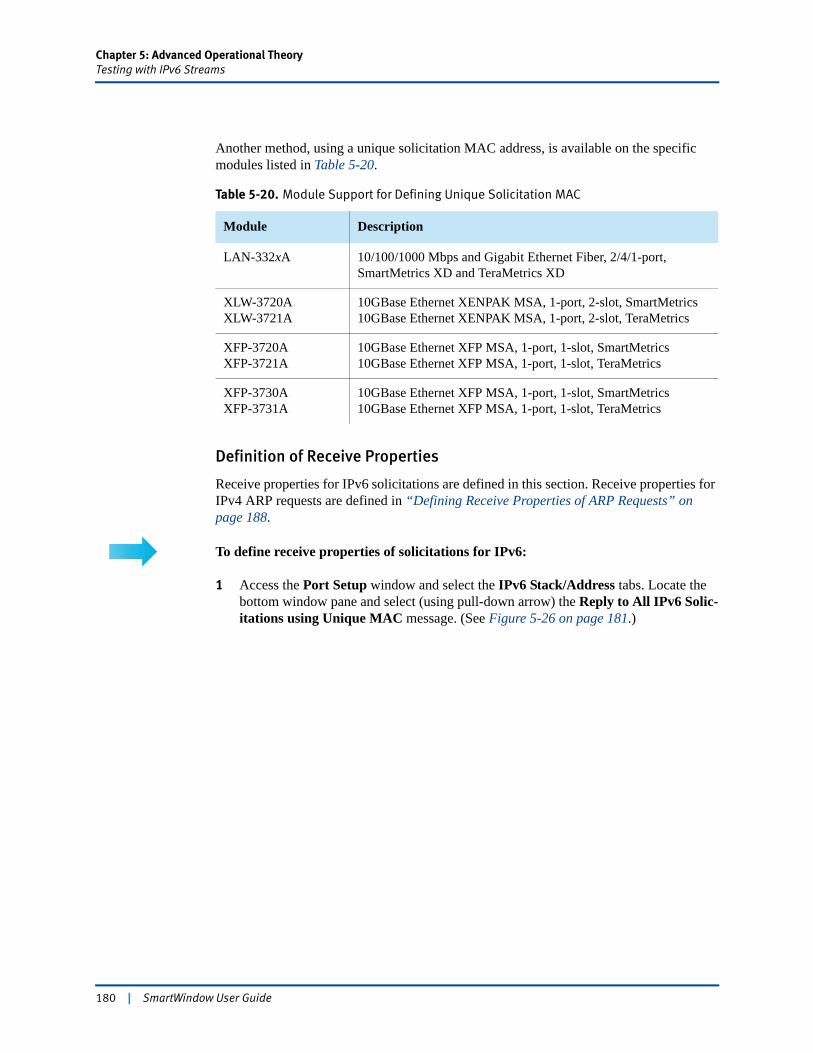
Chapter 5: Advanced Operational TheoryTesting with IPv6 Streams
Another method, using a unique solicitation MAC address, is available on the specific modules listed in Table 5-20.
Definition of Receive Properties
Receive properties for IPv6 solicitations are defined in this section. Receive properties for IPv4 ARP requests are defined in “Defining Receive Properties of ARP Requests” on page 188.
To define receive properties of solicitations for IPv6:
1 Access the Port Setup window and select the IPv6 Stack/Address tabs. Locate the bottom window pane and select (using pull-down arrow) the Reply to All IPv6 Solic-itations using Unique MAC message. (See Figure 5-26 on page 181.)
Table 5-20. Module Support for Defining Unique Solicitation MAC
Module Description
LAN-332xA 10/100/1000 Mbps and Gigabit Ethernet Fiber, 2/4/1-port, SmartMetrics XD and TeraMetrics XD
XLW-3720AXLW-3721A
10GBase Ethernet XENPAK MSA, 1-port, 2-slot, SmartMetrics10GBase Ethernet XENPAK MSA, 1-port, 2-slot, TeraMetrics
XFP-3720AXFP-3721A
10GBase Ethernet XFP MSA, 1-port, 1-slot, SmartMetrics10GBase Ethernet XFP MSA, 1-port, 1-slot, TeraMetrics
XFP-3730AXFP-3731A
10GBase Ethernet XFP MSA, 1-port, 1-slot, SmartMetrics10GBase Ethernet XFP MSA, 1-port, 1-slot, TeraMetrics
180 | SmartWindow User Guide
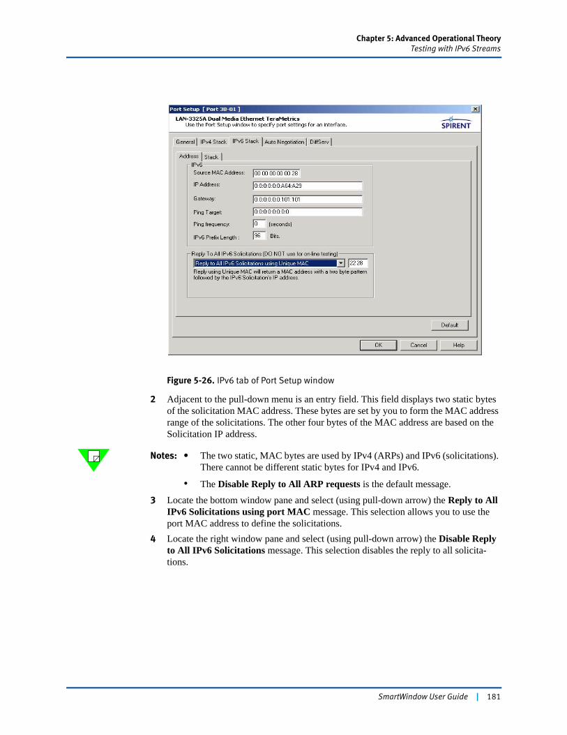
Chapter 5: Advanced Operational TheoryTesting with IPv6 Streams
Figure 5-26. IPv6 tab of Port Setup window
2 Adjacent to the pull-down menu is an entry field. This field displays two static bytes of the solicitation MAC address. These bytes are set by you to form the MAC address range of the solicitations. The other four bytes of the MAC address are based on the Solicitation IP address.
Notes: • The two static, MAC bytes are used by IPv4 (ARPs) and IPv6 (solicitations). There cannot be different static bytes for IPv4 and IPv6.
• The Disable Reply to All ARP requests is the default message.
3 Locate the bottom window pane and select (using pull-down arrow) the Reply to All IPv6 Solicitations using port MAC message. This selection allows you to use the port MAC address to define the solicitations.
4 Locate the right window pane and select (using pull-down arrow) the Disable Reply to All IPv6 Solicitations message. This selection disables the reply to all solicita-tions.
SmartWindow User Guide | 181
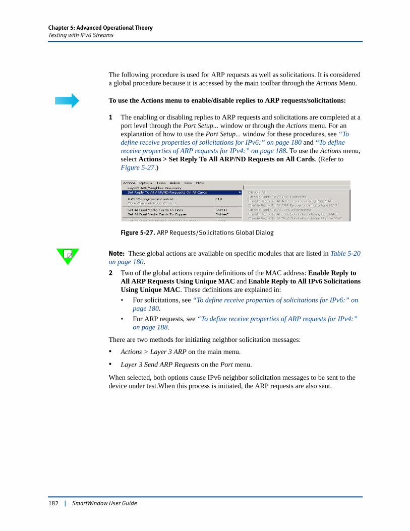
Chapter 5: Advanced Operational TheoryTesting with IPv6 Streams
The following procedure is used for ARP requests as well as solicitations. It is considered a global procedure because it is accessed by the main toolbar through the Actions Menu.
To use the Actions menu to enable/disable replies to ARP requests/solicitations:
1 The enabling or disabling replies to ARP requests and solicitations are completed at a port level through the Port Setup... window or through the Actions menu. For an explanation of how to use the Port Setup... window for these procedures, see “To define receive properties of solicitations for IPv6:” on page 180 and “To define receive properties of ARP requests for IPv4:” on page 188. To use the Actions menu, select Actions > Set Reply To All ARP/ND Requests on All Cards. (Refer to Figure 5-27.)
Figure 5-27. ARP Requests/Solicitations Global Dialog
Note: These global actions are available on specific modules that are listed in Table 5-20 on page 180.2 Two of the global actions require definitions of the MAC address: Enable Reply to
All ARP Requests Using Unique MAC and Enable Reply to All IPv6 Solicitations Using Unique MAC. These definitions are explained in:• For solicitations, see “To define receive properties of solicitations for IPv6:” on
page 180.• For ARP requests, see “To define receive properties of ARP requests for IPv4:”
on page 188.
There are two methods for initiating neighbor solicitation messages:
• Actions > Layer 3 ARP on the main menu.
• Layer 3 Send ARP Requests on the Port menu.
When selected, both options cause IPv6 neighbor solicitation messages to be sent to the device under test.When this process is initiated, the ARP requests are also sent.
182 | SmartWindow User Guide
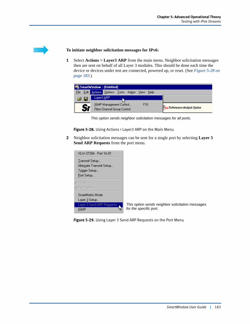
Chapter 5: Advanced Operational TheoryTesting with IPv6 Streams
To initiate neighbor solicitation messages for IPv6:
1 Select Actions > Layer3 ARP from the main menu. Neighbor solicitation messages then are sent on behalf of all Layer 3 modules. This should be done each time the device or devices under test are connected, powered up, or reset. (See Figure 5-28 on page 183.)
Figure 5-28. Using Actions > Layer3 ARP on the Main Menu
2 Neighbor solicitation messages can be sent for a single port by selecting Layer 3 Send ARP Requests from the port menu.
Figure 5-29. Using Layer 3 Send ARP Requests on the Port Menu
This option sends neighbor solicitation messages for all ports.
This option sends neighbor solicitation messages for the specific port.
SmartWindow User Guide | 183
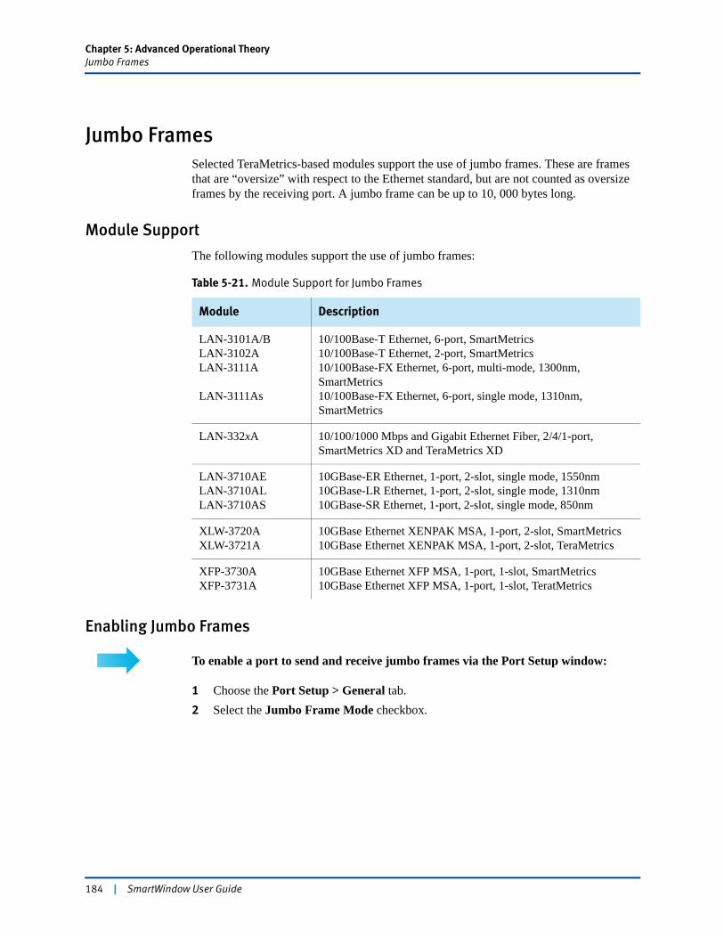
Chapter 5: Advanced Operational TheoryJumbo Frames
Jumbo FramesSelected TeraMetrics-based modules support the use of jumbo frames. These are frames that are “oversize” with respect to the Ethernet standard, but are not counted as oversize frames by the receiving port. A jumbo frame can be up to 10, 000 bytes long.
Module Support
The following modules support the use of jumbo frames:
Enabling Jumbo Frames
To enable a port to send and receive jumbo frames via the Port Setup window:
1 Choose the Port Setup > General tab.2 Select the Jumbo Frame Mode checkbox.
Table 5-21. Module Support for Jumbo Frames
Module Description
LAN-3101A/BLAN-3102ALAN-3111A
LAN-3111As
10/100Base-T Ethernet, 6-port, SmartMetrics10/100Base-T Ethernet, 2-port, SmartMetrics10/100Base-FX Ethernet, 6-port, multi-mode, 1300nm, SmartMetrics10/100Base-FX Ethernet, 6-port, single mode, 1310nm, SmartMetrics
LAN-332xA 10/100/1000 Mbps and Gigabit Ethernet Fiber, 2/4/1-port, SmartMetrics XD and TeraMetrics XD
LAN-3710AELAN-3710ALLAN-3710AS
10GBase-ER Ethernet, 1-port, 2-slot, single mode, 1550nm10GBase-LR Ethernet, 1-port, 2-slot, single mode, 1310nm10GBase-SR Ethernet, 1-port, 2-slot, single mode, 850nm
XLW-3720AXLW-3721A
10GBase Ethernet XENPAK MSA, 1-port, 2-slot, SmartMetrics10GBase Ethernet XENPAK MSA, 1-port, 2-slot, TeraMetrics
XFP-3730AXFP-3731A
10GBase Ethernet XFP MSA, 1-port, 1-slot, SmartMetrics10GBase Ethernet XFP MSA, 1-port, 1-slot, TeratMetrics
184 | SmartWindow User Guide
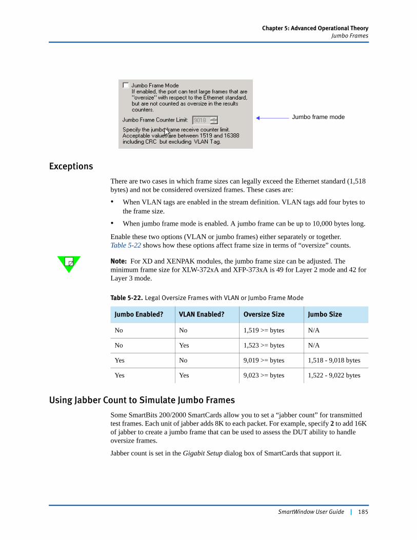
Chapter 5: Advanced Operational TheoryJumbo Frames
Exceptions
There are two cases in which frame sizes can legally exceed the Ethernet standard (1,518 bytes) and not be considered oversized frames. These cases are:
• When VLAN tags are enabled in the stream definition. VLAN tags add four bytes to the frame size.
• When jumbo frame mode is enabled. A jumbo frame can be up to 10,000 bytes long.
Enable these two options (VLAN or jumbo frames) either separately or together. Table 5-22 shows how these options affect frame size in terms of “oversize” counts.
Note: For XD and XENPAK modules, the jumbo frame size can be adjusted. The minimum frame size for XLW-372xA and XFP-373xA is 49 for Layer 2 mode and 42 for Layer 3 mode.
Using Jabber Count to Simulate Jumbo Frames
Some SmartBits 200/2000 SmartCards allow you to set a “jabber count” for transmitted test frames. Each unit of jabber adds 8K to each packet. For example, specify 2 to add 16K of jabber to create a jumbo frame that can be used to assess the DUT ability to handle oversize frames.
Jabber count is set in the Gigabit Setup dialog box of SmartCards that support it.
Jumbo frame mode
Table 5-22. Legal Oversize Frames with VLAN or Jumbo Frame Mode
Jumbo Enabled? VLAN Enabled? Oversize Size Jumbo Size
No No 1,519 >= bytes N/A
No Yes 1,523 >= bytes N/A
Yes No 9,019 >= bytes 1,518 - 9,018 bytes
Yes Yes 9,023 >= bytes 1,522 - 9,022 bytes
SmartWindow User Guide | 185
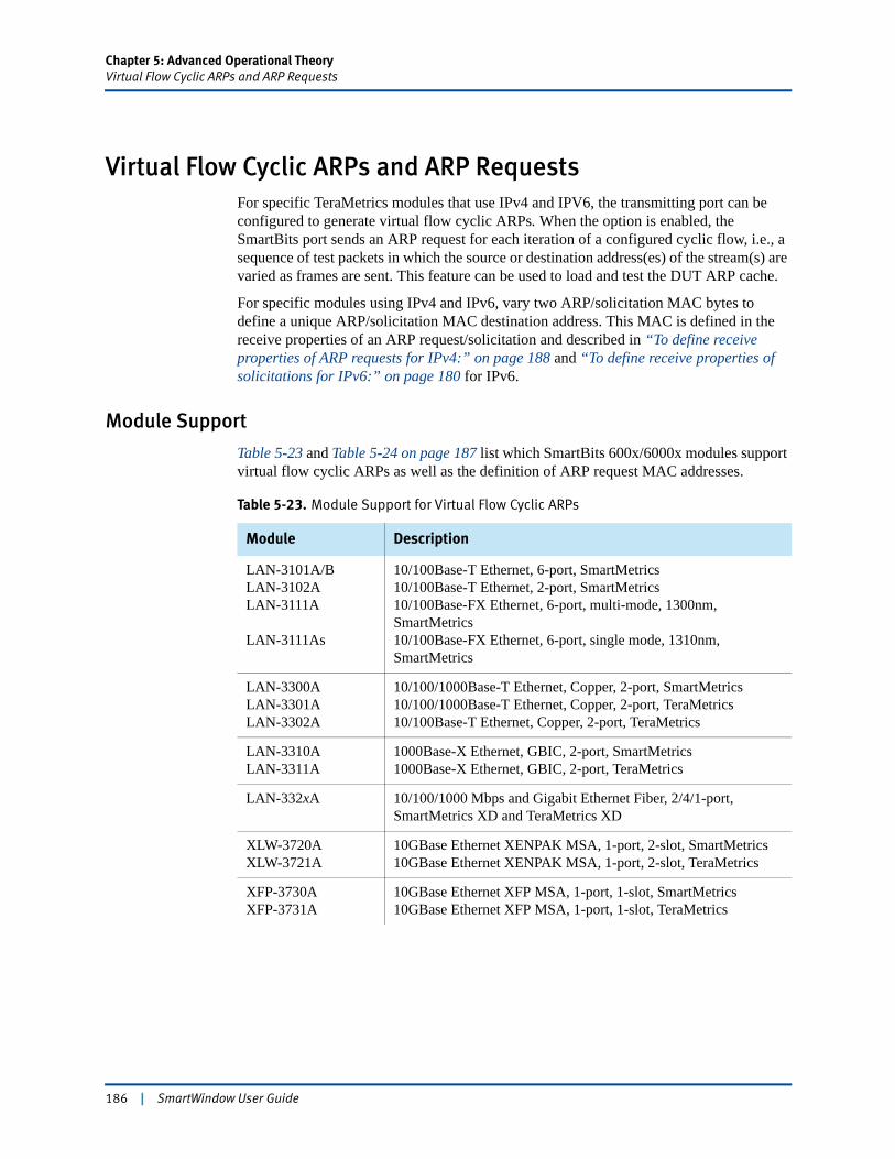
Chapter 5: Advanced Operational TheoryVirtual Flow Cyclic ARPs and ARP Requests
Virtual Flow Cyclic ARPs and ARP Requests For specific TeraMetrics modules that use IPv4 and IPV6, the transmitting port can be configured to generate virtual flow cyclic ARPs. When the option is enabled, the SmartBits port sends an ARP request for each iteration of a configured cyclic flow, i.e., a sequence of test packets in which the source or destination address(es) of the stream(s) are varied as frames are sent. This feature can be used to load and test the DUT ARP cache.
For specific modules using IPv4 and IPv6, vary two ARP/solicitation MAC bytes to define a unique ARP/solicitation MAC destination address. This MAC is defined in the receive properties of an ARP request/solicitation and described in “To define receive properties of ARP requests for IPv4:” on page 188 and “To define receive properties of solicitations for IPv6:” on page 180 for IPv6.
Module Support
Table 5-23 and Table 5-24 on page 187 list which SmartBits 600x/6000x modules support virtual flow cyclic ARPs as well as the definition of ARP request MAC addresses.
Table 5-23. Module Support for Virtual Flow Cyclic ARPs
Module Description
LAN-3101A/BLAN-3102ALAN-3111A
LAN-3111As
10/100Base-T Ethernet, 6-port, SmartMetrics10/100Base-T Ethernet, 2-port, SmartMetrics10/100Base-FX Ethernet, 6-port, multi-mode, 1300nm, SmartMetrics10/100Base-FX Ethernet, 6-port, single mode, 1310nm, SmartMetrics
LAN-3300ALAN-3301ALAN-3302A
10/100/1000Base-T Ethernet, Copper, 2-port, SmartMetrics10/100/1000Base-T Ethernet, Copper, 2-port, TeraMetrics10/100Base-T Ethernet, Copper, 2-port, TeraMetrics
LAN-3310ALAN-3311A
1000Base-X Ethernet, GBIC, 2-port, SmartMetrics1000Base-X Ethernet, GBIC, 2-port, TeraMetrics
LAN-332xA 10/100/1000 Mbps and Gigabit Ethernet Fiber, 2/4/1-port, SmartMetrics XD and TeraMetrics XD
XLW-3720AXLW-3721A
10GBase Ethernet XENPAK MSA, 1-port, 2-slot, SmartMetrics10GBase Ethernet XENPAK MSA, 1-port, 2-slot, TeraMetrics
XFP-3730AXFP-3731A
10GBase Ethernet XFP MSA, 1-port, 1-slot, SmartMetrics10GBase Ethernet XFP MSA, 1-port, 1-slot, TeraMetrics
186 | SmartWindow User Guide
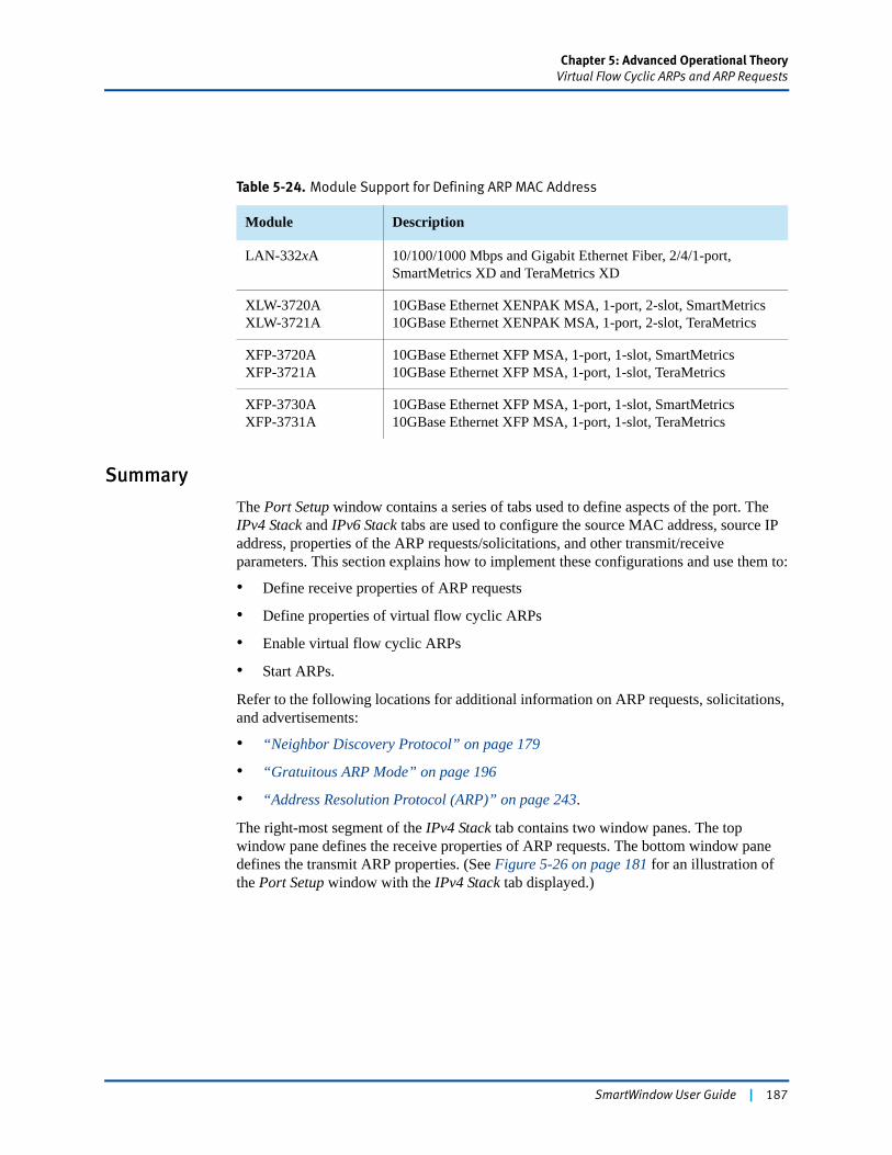
Chapter 5: Advanced Operational TheoryVirtual Flow Cyclic ARPs and ARP Requests
Summary
The Port Setup window contains a series of tabs used to define aspects of the port. The IPv4 Stack and IPv6 Stack tabs are used to configure the source MAC address, source IP address, properties of the ARP requests/solicitations, and other transmit/receive parameters. This section explains how to implement these configurations and use them to:
• Define receive properties of ARP requests
• Define properties of virtual flow cyclic ARPs
• Enable virtual flow cyclic ARPs
• Start ARPs.
Refer to the following locations for additional information on ARP requests, solicitations, and advertisements:
• “Neighbor Discovery Protocol” on page 179
• “Gratuitous ARP Mode” on page 196
• “Address Resolution Protocol (ARP)” on page 243.
The right-most segment of the IPv4 Stack tab contains two window panes. The top window pane defines the receive properties of ARP requests. The bottom window pane defines the transmit ARP properties. (See Figure 5-26 on page 181 for an illustration of the Port Setup window with the IPv4 Stack tab displayed.)
Table 5-24. Module Support for Defining ARP MAC Address
Module Description
LAN-332xA 10/100/1000 Mbps and Gigabit Ethernet Fiber, 2/4/1-port, SmartMetrics XD and TeraMetrics XD
XLW-3720AXLW-3721A
10GBase Ethernet XENPAK MSA, 1-port, 2-slot, SmartMetrics10GBase Ethernet XENPAK MSA, 1-port, 2-slot, TeraMetrics
XFP-3720AXFP-3721A
10GBase Ethernet XFP MSA, 1-port, 1-slot, SmartMetrics10GBase Ethernet XFP MSA, 1-port, 1-slot, TeraMetrics
XFP-3730AXFP-3731A
10GBase Ethernet XFP MSA, 1-port, 1-slot, SmartMetrics10GBase Ethernet XFP MSA, 1-port, 1-slot, TeraMetrics
SmartWindow User Guide | 187
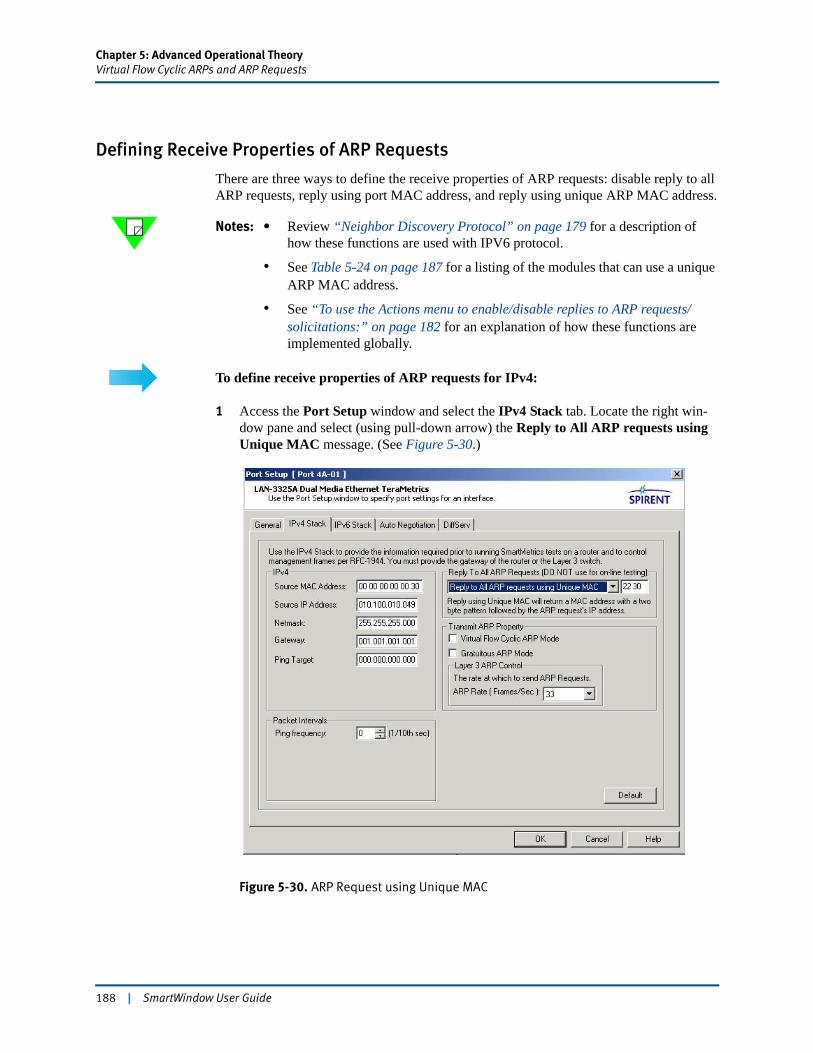
Chapter 5: Advanced Operational TheoryVirtual Flow Cyclic ARPs and ARP Requests
Defining Receive Properties of ARP Requests
There are three ways to define the receive properties of ARP requests: disable reply to all ARP requests, reply using port MAC address, and reply using unique ARP MAC address.
Notes: • Review “Neighbor Discovery Protocol” on page 179 for a description of how these functions are used with IPV6 protocol.
• See Table 5-24 on page 187 for a listing of the modules that can use a unique ARP MAC address.
• See “To use the Actions menu to enable/disable replies to ARP requests/solicitations:” on page 182 for an explanation of how these functions are implemented globally.
To define receive properties of ARP requests for IPv4:
1 Access the Port Setup window and select the IPv4 Stack tab. Locate the right win-dow pane and select (using pull-down arrow) the Reply to All ARP requests using Unique MAC message. (See Figure 5-30.)
Figure 5-30. ARP Request using Unique MAC
188 | SmartWindow User Guide
Chapter 5: Advanced Operational TheoryVirtual Flow Cyclic ARPs and ARP Requests
2 Adjacent to the pull-down menu is an entry field. This field displays two static bytes of the ARP MAC address. These bytes are set by you to form the MAC address range of the ARP requests. The other four bytes of the MAC address are based on the ARP IP address.
Notes: • The two static, MAC bytes are used by IPv4 (ARPs) and IPv6 (solicitations). There cannot be different static bytes for IPv4 and IPv6.
• The Disable Reply to All ARP requests is the default message.
3 Locate the right window pane and select (using pull-down arrow) the Reply to All ARP requests using port MAC message. This selection allows you to use the port MAC address to define the destination ARPs.
4 Locate the right window pane and select (using pull-down arrow) the Disable Reply to All ARP requests message. This selection disables the reply to all ARP requests.
Defining Properties of Virtual Flow Cyclic ARPs
The pane located directly below the Reply to All ARP Requests (DO NOT use for online testing) pane is labeled Transmit ARP Property. Located within this pane is the checkbox that is used to enable virtual flow cyclic ARPs. (See Figure 5-30 on page 188. Table 5-25 provides a quick overview of how to set up virtual flow cyclic ARPs.)
Table 5-25. Module Support for Virtual Flow Cyclic ARPs
Step Description
1 Enable Virtual Flow Cyclic ARP Mode in the Port Setup window.
2 Enable SmartMetric Mode on the Port menu.
3 Open the Streams Setup window and add test streams.
4 Select the stream(s), then click Edit to open the Tx Control Panel.
SmartWindow User Guide | 189
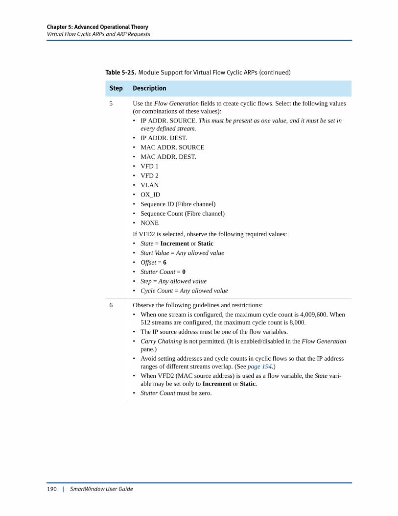
Chapter 5: Advanced Operational TheoryVirtual Flow Cyclic ARPs and ARP Requests
5 Use the Flow Generation fields to create cyclic flows. Select the following values (or combinations of these values):• IP ADDR. SOURCE. This must be present as one value, and it must be set in
every defined stream.• IP ADDR. DEST.• MAC ADDR. SOURCE• MAC ADDR. DEST.• VFD 1• VFD 2• VLAN• OX_ID• Sequence ID (Fibre channel)• Sequence Count (Fibre channel)• NONE
If VFD2 is selected, observe the following required values:• State = Increment or Static• Start Value = Any allowed value• Offset = 6• Stutter Count = 0• Step = Any allowed value• Cycle Count = Any allowed value
6 Observe the following guidelines and restrictions:• When one stream is configured, the maximum cycle count is 4,009,600. When
512 streams are configured, the maximum cycle count is 8,000. • The IP source address must be one of the flow variables.• Carry Chaining is not permitted. (It is enabled/disabled in the Flow Generation
pane.)• Avoid setting addresses and cycle counts in cyclic flows so that the IP address
ranges of different streams overlap. (See page 194.)• When VFD2 (MAC source address) is used as a flow variable, the State vari-
able may be set only to Increment or Static.• Stutter Count must be zero.
Table 5-25. Module Support for Virtual Flow Cyclic ARPs (continued)
Step Description
190 | SmartWindow User Guide
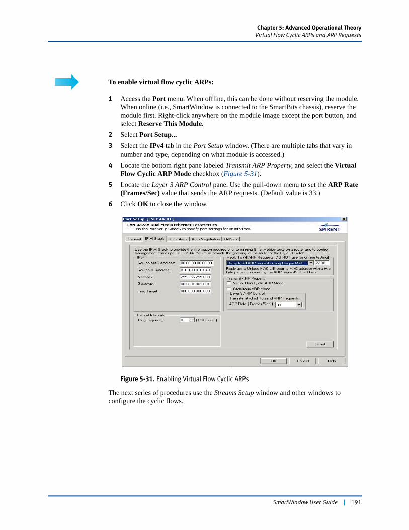
Chapter 5: Advanced Operational TheoryVirtual Flow Cyclic ARPs and ARP Requests
To enable virtual flow cyclic ARPs:
1 Access the Port menu. When offline, this can be done without reserving the module. When online (i.e., SmartWindow is connected to the SmartBits chassis), reserve the module first. Right-click anywhere on the module image except the port button, and select Reserve This Module.
2 Select Port Setup...3 Select the IPv4 tab in the Port Setup window. (There are multiple tabs that vary in
number and type, depending on what module is accessed.)4 Locate the bottom right pane labeled Transmit ARP Property, and select the Virtual
Flow Cyclic ARP Mode checkbox (Figure 5-31).5 Locate the Layer 3 ARP Control pane. Use the pull-down menu to set the ARP Rate
(Frames/Sec) value that sends the ARP requests. (Default value is 33.)6 Click OK to close the window.
Figure 5-31. Enabling Virtual Flow Cyclic ARPs
The next series of procedures use the Streams Setup window and other windows to configure the cyclic flows.
SmartWindow User Guide | 191
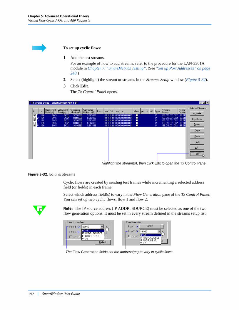
Chapter 5: Advanced Operational TheoryVirtual Flow Cyclic ARPs and ARP Requests
To set up cyclic flows:
1 Add the test streams.For an example of how to add streams, refer to the procedure for the LAN-3301A module in Chapter 7, “SmartMetrics Testing”. (See “Set up Port Addresses” on page 248.)
2 Select (highlight) the stream or streams in the Streams Setup window (Figure 5-32).3 Click Edit.
The Tx Control Panel opens.
Figure 5-32. Editing Streams
Cyclic flows are created by sending test frames while incrementing a selected address field (or fields) in each frame.
Select which address field(s) to vary in the Flow Generation pane of the Tx Control Panel. You can set up two cyclic flows, flow 1 and flow 2.
Note: The IP source address (IP ADDR. SOURCE) must be selected as one of the two flow generation options. It must be set in every stream defined in the streams setup list.
Highlight the stream(s), then click Edit to open the Tx Control Panel.
The Flow Generation fields set the address(es) to vary in cyclic flows.
192 | SmartWindow User Guide
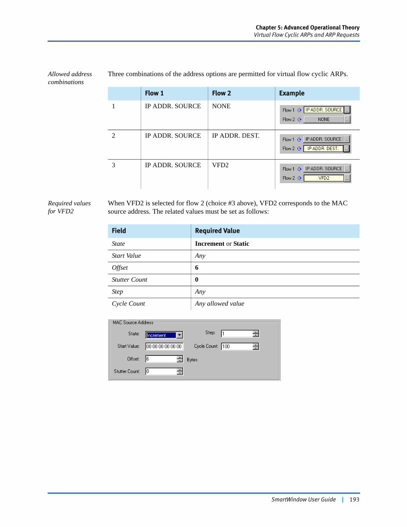
Chapter 5: Advanced Operational TheoryVirtual Flow Cyclic ARPs and ARP Requests
Allowed address combinations
Three combinations of the address options are permitted for virtual flow cyclic ARPs.
Required values for VFD2
When VFD2 is selected for flow 2 (choice #3 above), VFD2 corresponds to the MAC source address. The related values must be set as follows:
Flow 1 Flow 2 Example
1 IP ADDR. SOURCE NONE
2 IP ADDR. SOURCE IP ADDR. DEST.
3 IP ADDR. SOURCE VFD2
Field Required Value
State Increment or Static
Start Value Any
Offset 6
Stutter Count 0
Step Any
Cycle Count Any allowed value
SmartWindow User Guide | 193
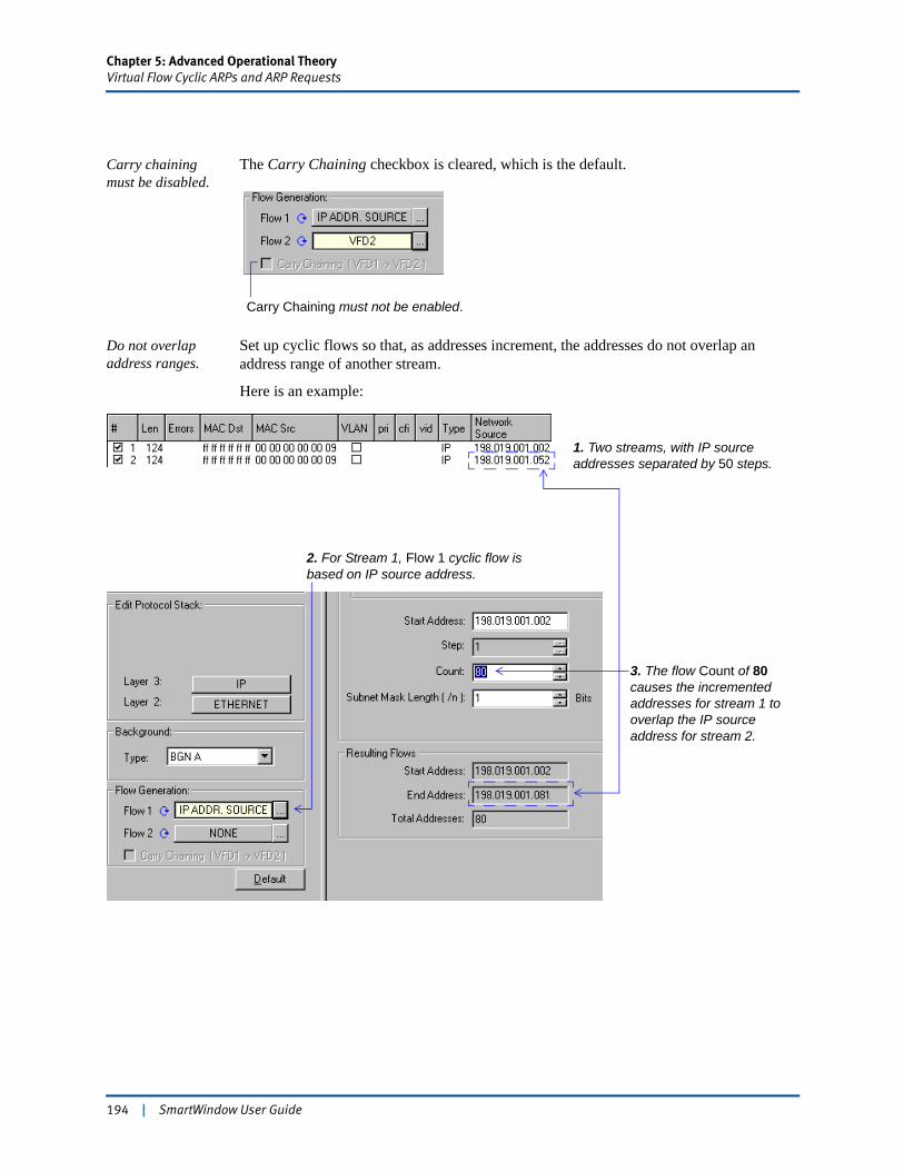
Chapter 5: Advanced Operational TheoryVirtual Flow Cyclic ARPs and ARP Requests
Carry chaining must be disabled.
The Carry Chaining checkbox is cleared, which is the default.
Do not overlap address ranges.
Set up cyclic flows so that, as addresses increment, the addresses do not overlap an address range of another stream.
Here is an example:
Carry Chaining must not be enabled.
2. For Stream 1, Flow 1 cyclic flow is based on IP source address.
3. The flow Count of 80 causes the incremented addresses for stream 1 to overlap the IP source address for stream 2.
1. Two streams, with IP source addresses separated by 50 steps.
194 | SmartWindow User Guide
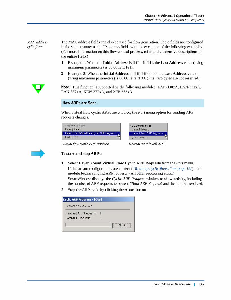
Chapter 5: Advanced Operational TheoryVirtual Flow Cyclic ARPs and ARP Requests
MAC address cylic flows
The MAC address fields can also be used for flow generation. These fields are configured in the same manner as the IP address fields with the exception of the following examples. (For more information on this flow control process, refer to the extensive descriptions in the online Help.)1 Example 1: When the Initial Address is ff ff ff ff ff f1, the Last Address value (using
maximum parameters) is 00 00 fe ff fe ff.2 Example 2: When the Initial Address is ff ff ff ff 00 00, the Last Address value
(using maximum parameters) is 00 00 fe fe ff 00. (First two bytes are not reserved.)
Note: This function is supported on the following modules: LAN-330xA, LAN-331xA, LAN-332xA, XLW-372xA, and XFP-373xA.
How ARPs are Sent
When virtual flow cyclic ARPs are enabled, the Port menu option for sending ARP requests changes.
To start and stop ARPs:
1 Select Layer 3 Send Virtual Flow Cyclic ARP Requests from the Port menu.If the stream configurations are correct (“To set up cyclic flows:” on page 192), the module begins sending ARP requests. (All other processing stops.)SmartWindow displays the Cyclic ARP Progress window to show activity, including the number of ARP requests to be sent (Total ARP Request) and the number resolved.
2 Stop the ARP cycle by clicking the Abort button.
Virtual flow cyclic ARP enabled. Normal (port-level) ARP
SmartWindow User Guide | 195
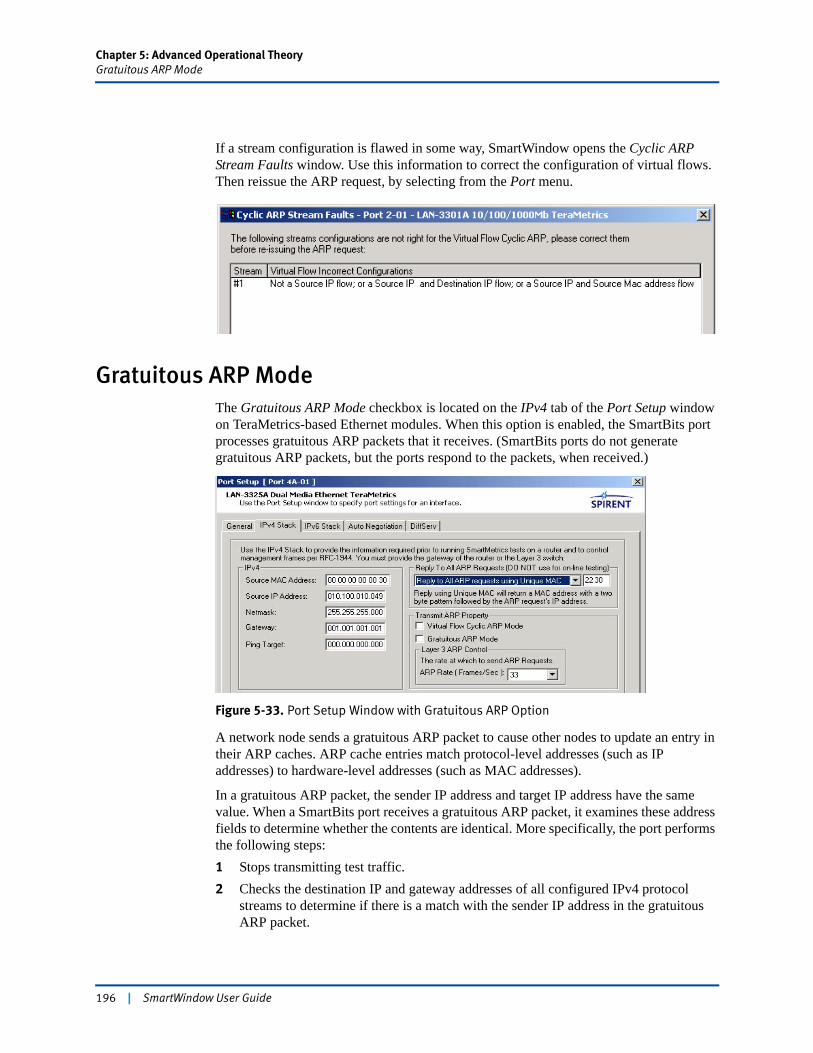
Chapter 5: Advanced Operational TheoryGratuitous ARP Mode
If a stream configuration is flawed in some way, SmartWindow opens the Cyclic ARP Stream Faults window. Use this information to correct the configuration of virtual flows. Then reissue the ARP request, by selecting from the Port menu.
Gratuitous ARP ModeThe Gratuitous ARP Mode checkbox is located on the IPv4 tab of the Port Setup window on TeraMetrics-based Ethernet modules. When this option is enabled, the SmartBits port processes gratuitous ARP packets that it receives. (SmartBits ports do not generate gratuitous ARP packets, but the ports respond to the packets, when received.)
Figure 5-33. Port Setup Window with Gratuitous ARP Option
A network node sends a gratuitous ARP packet to cause other nodes to update an entry in their ARP caches. ARP cache entries match protocol-level addresses (such as IP addresses) to hardware-level addresses (such as MAC addresses).
In a gratuitous ARP packet, the sender IP address and target IP address have the same value. When a SmartBits port receives a gratuitous ARP packet, it examines these address fields to determine whether the contents are identical. More specifically, the port performs the following steps:1 Stops transmitting test traffic.2 Checks the destination IP and gateway addresses of all configured IPv4 protocol
streams to determine if there is a match with the sender IP address in the gratuitous ARP packet.
196 | SmartWindow User Guide
Chapter 5: Advanced Operational TheoryGratuitous ARP Mode
3 Updates the stream destination hardware address with the address from the gratuitous ARP packet.
4 Resumes transmission as quickly as possible, leaving counters and settings unaffected by the interruption.
Counters When gratuitous ARP mode is enabled, gratuitous ARP packets received by the port are listed in the SmartCounters window. These packets are identified as gratuitous ARP requests received.
Gratuitous ARP Counter Behavior on TeraMetrics Cards
Incrementing the Gratuitous ARP Counters
The gratuitous ARP counter does not count the number of gratuitous ARPs received by the port. It increments by one for each incoming gratuitous ARP that matches one or more of the streams configured on the port. Once a stream is changed by a gratuitous ARP, subsequent identical gratuitous ARPs are ignored and do not result in further incrementaiton of the counter.
Zeroing the Gratuitous ARP Counter
The gratuitous ARP counter is zeroed on any port when:
• All counters are cleared on the port.
• ARPs are initiated from the port.
• The ARP mode is changed on the port (from gratuitous to standard or standard to gratuitous).
SmartWindow User Guide | 197

198 | SmartWindow User Guide
Chapter 6
Traditional LAN Testing
SmartWindow is a highly effective front panel GUI designed for developers and QA personnel who need to create both traditional and custom tests. SmartWindow offers test parameters recommended in the following supported RFCs:
• RFC 1242 – Benchmarking Terminology for Network Interconnection Devices
• RFC 2544 – Benchmarking Methodology for Network Interconnect Devices
• RFC 2285 – Benchmarking Terminology for LAN Switching Devices
In this chapter...
• Traditional Testing vs. SmartMetrics . . . . 200
• Testing Cable Modems . . . . 203
• Testing VLAN Tagging Across a Gigabit Uplink . . . . 214
• Between Layer 2 and Layer 3 . . . . 227
• Testing QOS for Gigabit Routers . . . . 228
SmartWindow User Guide | 199
Chapter 6: Traditional LAN TestingTraditional Testing vs. SmartMetrics
Traditional Testing vs. SmartMetricsLAN SmartCards and some LAN modules provide two types of Ethernet testing: traditional mode and SmartMetrics mode. Other cards/modules only provide traditional mode testing. Each of these two testing modes uses different windows and displays in the user interface. For this reason, be sure to review the text and illustrations for specific model numbers that identify what mode(s) are supported by the card/module that is being used.
Traditional Mode (for Simulating Layer 2 and Layer 3)
Refers to the basic capabilities of all cards, which include:
• Customizing packet content with a protocol editor, including the ability to intersperse alternate traffic with regular streams.
• Monitoring and validating packets with user-definable triggers.
• Defining and using VLAN tags.
• Adjusting preamble length, auto-negotiation, frame capture, and packet counting based on events.
• Generating packets up to and beyond wire speed plus variety of transmission modes as well as ability to dynamically vary packet gap and length (without FCS) during transmission.
Figure 6-1 shows the Port Setup window for the LAN-3100A (traditional mode only module). Refer to Chapter 4, “Basic Operational Theory”, Chapter 5, “Advanced Operational Theory”, and the online Help for additional information on traditional mode testing.
Notes: • SmartBits 200/2000 SmartCards and SmartBits 600x/6000x modules each use different versions of SmartCounters.
• For the two types of SmartCounters, a listing of cards/modules is given in “SmartCounters” on page 131. This chapter and Chapter 7, “SmartMetrics Testing” describes the SmartCounters display that is used for SmartBits 200/2000 SmartCards. Chapter 8, “Testing Gigabit Routers,”Chapter 11, “Testing POS Routers,” and Chapter 13, “Testing Storage Area Networks”describe the SmartCounters used for the SmartBits 600x/6000x modules.
• The LAN-3100A provides counters for dribble values. Other traditional mode and traditional/SmartMetrics mode cards/modules do not have this capability. The online Help has a complete description of this function.
200 | SmartWindow User Guide
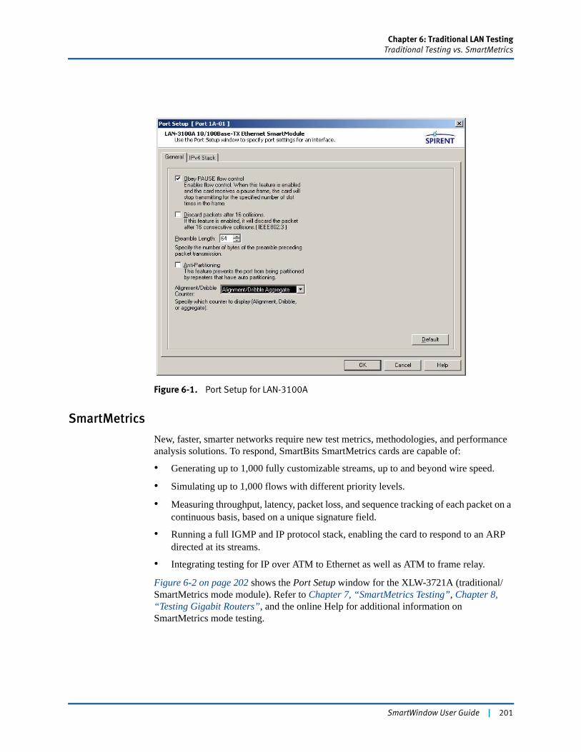
Chapter 6: Traditional LAN TestingTraditional Testing vs. SmartMetrics
Figure 6-1. Port Setup for LAN-3100A
SmartMetrics
New, faster, smarter networks require new test metrics, methodologies, and performance analysis solutions. To respond, SmartBits SmartMetrics cards are capable of:
• Generating up to 1,000 fully customizable streams, up to and beyond wire speed.
• Simulating up to 1,000 flows with different priority levels.
• Measuring throughput, latency, packet loss, and sequence tracking of each packet on a continuous basis, based on a unique signature field.
• Running a full IGMP and IP protocol stack, enabling the card to respond to an ARP directed at its streams.
• Integrating testing for IP over ATM to Ethernet as well as ATM to frame relay.
Figure 6-2 on page 202 shows the Port Setup window for the XLW-3721A (traditional/SmartMetrics mode module). Refer to Chapter 7, “SmartMetrics Testing”, Chapter 8, “Testing Gigabit Routers”, and the online Help for additional information on SmartMetrics mode testing.
SmartWindow User Guide | 201
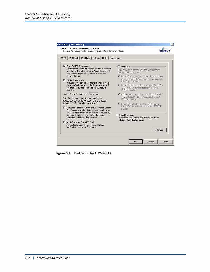
Chapter 6: Traditional LAN TestingTraditional Testing vs. SmartMetrics
Figure 6-2. Port Setup for XLW-3721A
202 | SmartWindow User Guide
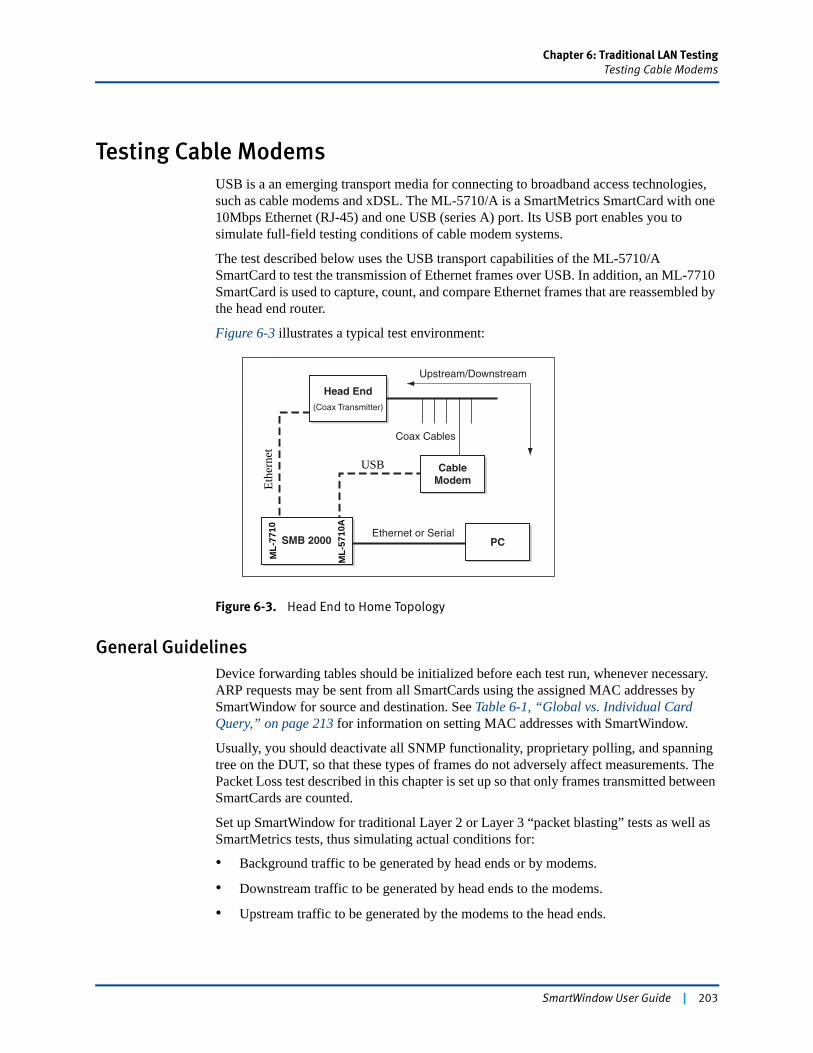
Chapter 6: Traditional LAN TestingTesting Cable Modems
Testing Cable ModemsUSB is a an emerging transport media for connecting to broadband access technologies, such as cable modems and xDSL. The ML-5710/A is a SmartMetrics SmartCard with one 10Mbps Ethernet (RJ-45) and one USB (series A) port. Its USB port enables you to simulate full-field testing conditions of cable modem systems.
The test described below uses the USB transport capabilities of the ML-5710/A SmartCard to test the transmission of Ethernet frames over USB. In addition, an ML-7710 SmartCard is used to capture, count, and compare Ethernet frames that are reassembled by the head end router.
Figure 6-3 illustrates a typical test environment:
Figure 6-3. Head End to Home Topology
General GuidelinesDevice forwarding tables should be initialized before each test run, whenever necessary. ARP requests may be sent from all SmartCards using the assigned MAC addresses by SmartWindow for source and destination. See Table 6-1, “Global vs. Individual Card Query,” on page 213 for information on setting MAC addresses with SmartWindow.
Usually, you should deactivate all SNMP functionality, proprietary polling, and spanning tree on the DUT, so that these types of frames do not adversely affect measurements. The Packet Loss test described in this chapter is set up so that only frames transmitted between SmartCards are counted.
Set up SmartWindow for traditional Layer 2 or Layer 3 “packet blasting” tests as well as SmartMetrics tests, thus simulating actual conditions for:
• Background traffic to be generated by head ends or by modems.
• Downstream traffic to be generated by head ends to the modems.
• Upstream traffic to be generated by the modems to the head ends.
Ethernet or Serial
Head End(Coax Transmitter)
SMB 2000
CableModem
Coax Cables
Upstream/Downstream
PC
USB
Ethe
rnet
ML-
7710
ML-
5710
A
SmartWindow User Guide | 203
Chapter 6: Traditional LAN TestingTesting Cable Modems
Packet Loss Test
This sample test uses a series of procedures:
Required Setup
The illustrated test configuration is based on the following setup:
• A SmartBits 2000 chassis with one ML-7710 SmartCard installed in slot 6 and oneML-5710/A SmartCard installed in slot 31.
• The SmartBits chassis is connected to a PC with SmartWindow via an Ethernet port.
• Port 4 is connected to a head end router, and port 31 is connected to a cable modem.
The ML-5710/A card allows you to test the performance of head end routers, whether the CPE is Ethernet or USB. For this Layer 2 test, configure slot 31 (ML-5710/A card) and slot 4 (ML-7710 card) for bi-directional USB transmission.
Connecting the Cables
To set up cabling:
1 Connect one end of the USB cable to the USB port in the ML-5710/A card in slot 31 and the other end to the USB port on the cable modem.
2 Connect one end of an Ethernet cable to the ML-7710 card in slot 4 and the other end to an Ethernet port on the head end router.
The capabilities of the system can now be tested.
Preparing the SUT
Configure the System Under Test (SUT) according to test needs. This simple Packet Loss test does not require extensive pre-configuration.
Procedure Description
1 Use triggers and the Protocol Editor, and set up bi-directional frames.
2 Transmit briefly in both directions to give the DUT time for address learning.
3 Capture packets to ensure that the correct frames are being received.
4 Clear SmartCounters.
5 Start the test.
6 Use SmartCounters to compute.
204 | SmartWindow User Guide
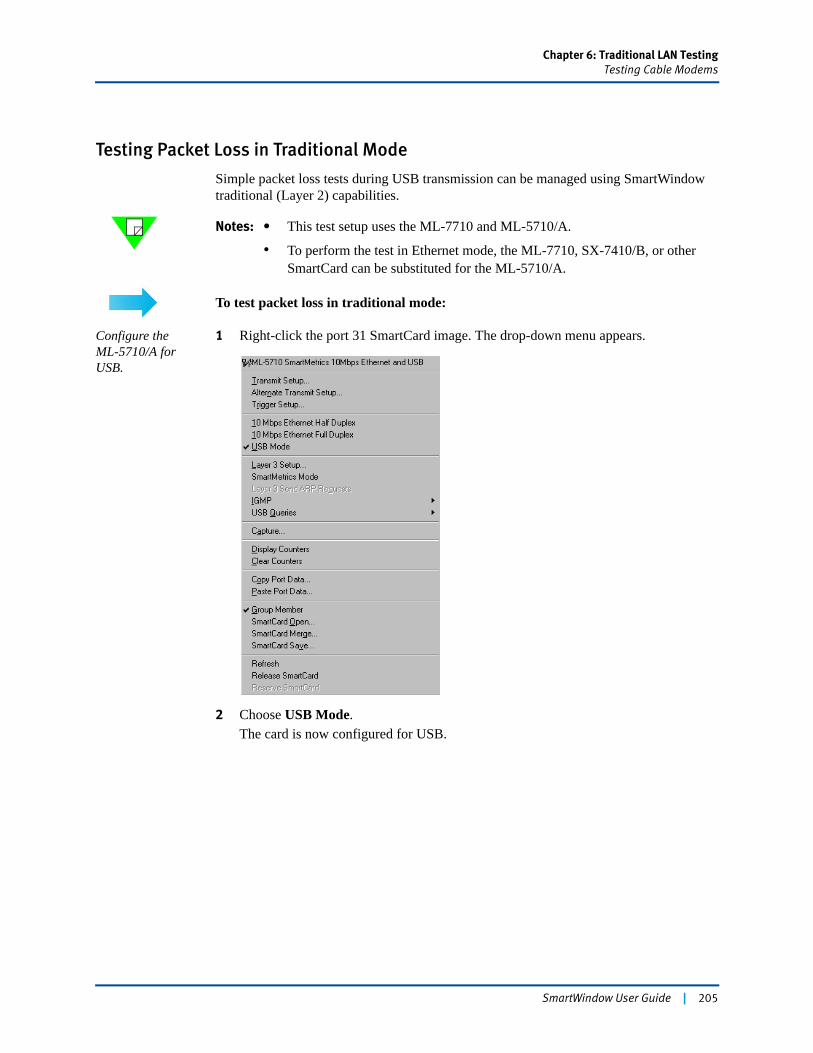
Chapter 6: Traditional LAN TestingTesting Cable Modems
Testing Packet Loss in Traditional Mode
Simple packet loss tests during USB transmission can be managed using SmartWindow traditional (Layer 2) capabilities.
Notes: • This test setup uses the ML-7710 and ML-5710/A.
• To perform the test in Ethernet mode, the ML-7710, SX-7410/B, or other SmartCard can be substituted for the ML-5710/A.
To test packet loss in traditional mode:
Configure the ML-5710/A for USB.
1 Right-click the port 31 SmartCard image. The drop-down menu appears.
2 Choose USB Mode.The card is now configured for USB.
SmartWindow User Guide | 205
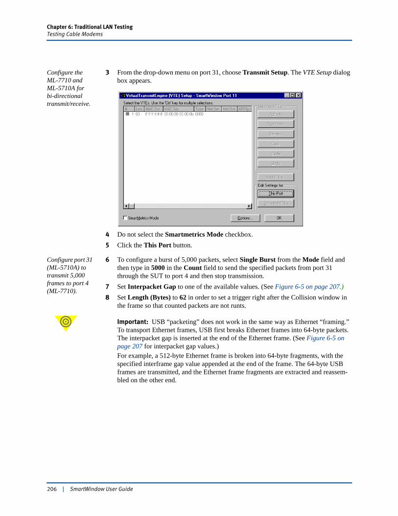
Chapter 6: Traditional LAN TestingTesting Cable Modems
Configure the ML-7710 and ML-5710A forbi-directional transmit/receive.
3 From the drop-down menu on port 31, choose Transmit Setup. The VTE Setup dialog box appears.
4 Do not select the Smartmetrics Mode checkbox.5 Click the This Port button.
Configure port 31 (ML-5710A) to transmit 5,000 frames to port 4 (ML-7710).
6 To configure a burst of 5,000 packets, select Single Burst from the Mode field and then type in 5000 in the Count field to send the specified packets from port 31 through the SUT to port 4 and then stop transmission.
7 Set Interpacket Gap to one of the available values. (See Figure 6-5 on page 207.)8 Set Length (Bytes) to 62 in order to set a trigger right after the Collision window in
the frame so that counted packets are not runts.
Important: USB “packeting” does not work in the same way as Ethernet “framing.” To transport Ethernet frames, USB first breaks Ethernet frames into 64-byte packets. The interpacket gap is inserted at the end of the Ethernet frame. (See Figure 6-5 on page 207 for interpacket gap values.)For example, a 512-byte Ethernet frame is broken into 64-byte fragments, with the specified interframe gap value appended at the end of the frame. The 64-byte USB frames are transmitted, and the Ethernet frame fragments are extracted and reassem-bled on the other end.
206 | SmartWindow User Guide
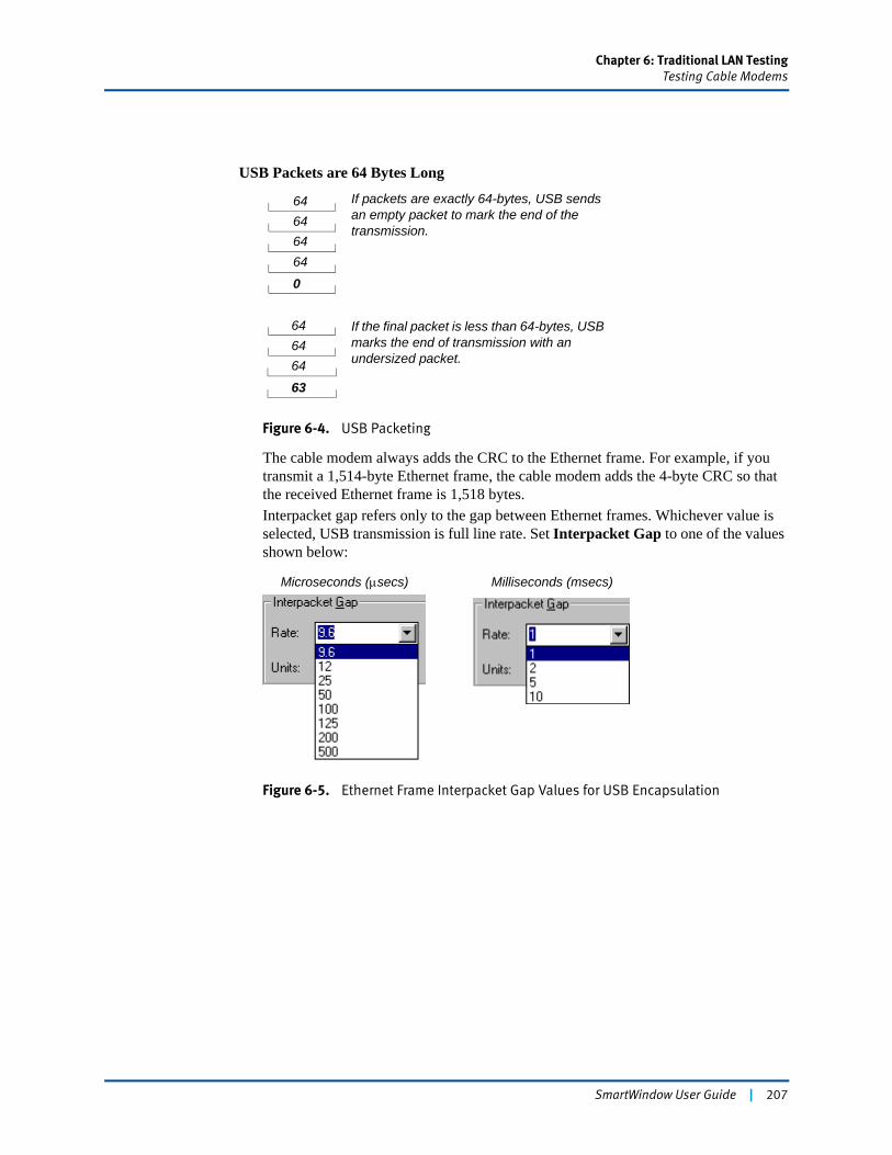
Chapter 6: Traditional LAN TestingTesting Cable Modems
Figure 6-4. USB Packeting
The cable modem always adds the CRC to the Ethernet frame. For example, if you transmit a 1,514-byte Ethernet frame, the cable modem adds the 4-byte CRC so that the received Ethernet frame is 1,518 bytes.Interpacket gap refers only to the gap between Ethernet frames. Whichever value is selected, USB transmission is full line rate. Set Interpacket Gap to one of the values shown below:
Figure 6-5. Ethernet Frame Interpacket Gap Values for USB Encapsulation
64646464
646464
63
USB Packets are 64 Bytes Long
If packets are exactly 64-bytes, USB sends an empty packet to mark the end of the transmission.
If the final packet is less than 64-bytes, USB marks the end of transmission with an undersized packet.
0
Microseconds (μsecs) Milliseconds (msecs)
SmartWindow User Guide | 207
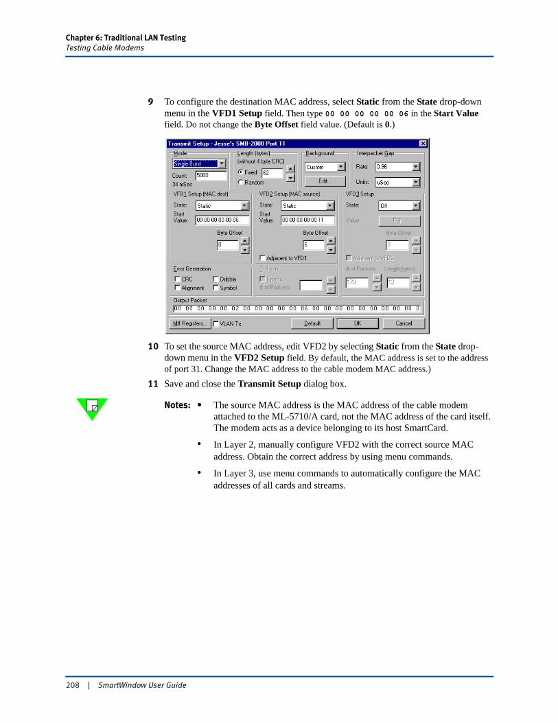
Chapter 6: Traditional LAN TestingTesting Cable Modems
9 To configure the destination MAC address, select Static from the State drop-down menu in the VFD1 Setup field. Then type 00 00 00 00 00 06 in the Start Value field. Do not change the Byte Offset field value. (Default is 0.)
10 To set the source MAC address, edit VFD2 by selecting Static from the State drop-down menu in the VFD2 Setup field. By default, the MAC address is set to the address of port 31. Change the MAC address to the cable modem MAC address.)
11 Save and close the Transmit Setup dialog box.
Notes: • The source MAC address is the MAC address of the cable modem attached to the ML-5710/A card, not the MAC address of the card itself. The modem acts as a device belonging to its host SmartCard.
• In Layer 2, manually configure VFD2 with the correct source MAC address. Obtain the correct address by using menu commands.
• In Layer 3, use menu commands to automatically configure the MAC addresses of all cards and streams.
208 | SmartWindow User Guide
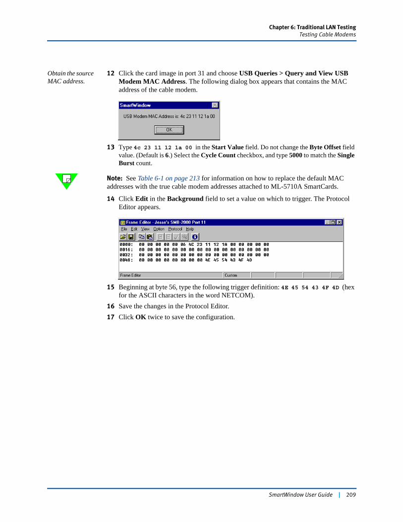
Chapter 6: Traditional LAN TestingTesting Cable Modems
Obtain the source MAC address.
12 Click the card image in port 31 and choose USB Queries > Query and View USB Modem MAC Address. The following dialog box appears that contains the MAC address of the cable modem.
13 Type 4c 23 11 12 1a 00 in the Start Value field. Do not change the Byte Offset field value. (Default is 6.) Select the Cycle Count checkbox, and type 5000 to match the Single Burst count.
Note: See Table 6-1 on page 213 for information on how to replace the default MAC addresses with the true cable modem addresses attached to ML-5710A SmartCards.
14 Click Edit in the Background field to set a value on which to trigger. The Protocol Editor appears.
15 Beginning at byte 56, type the following trigger definition: 4E 45 54 43 4F 4D (hex for the ASCII characters in the word NETCOM).
16 Save the changes in the Protocol Editor.17 Click OK twice to save the configuration.
SmartWindow User Guide | 209
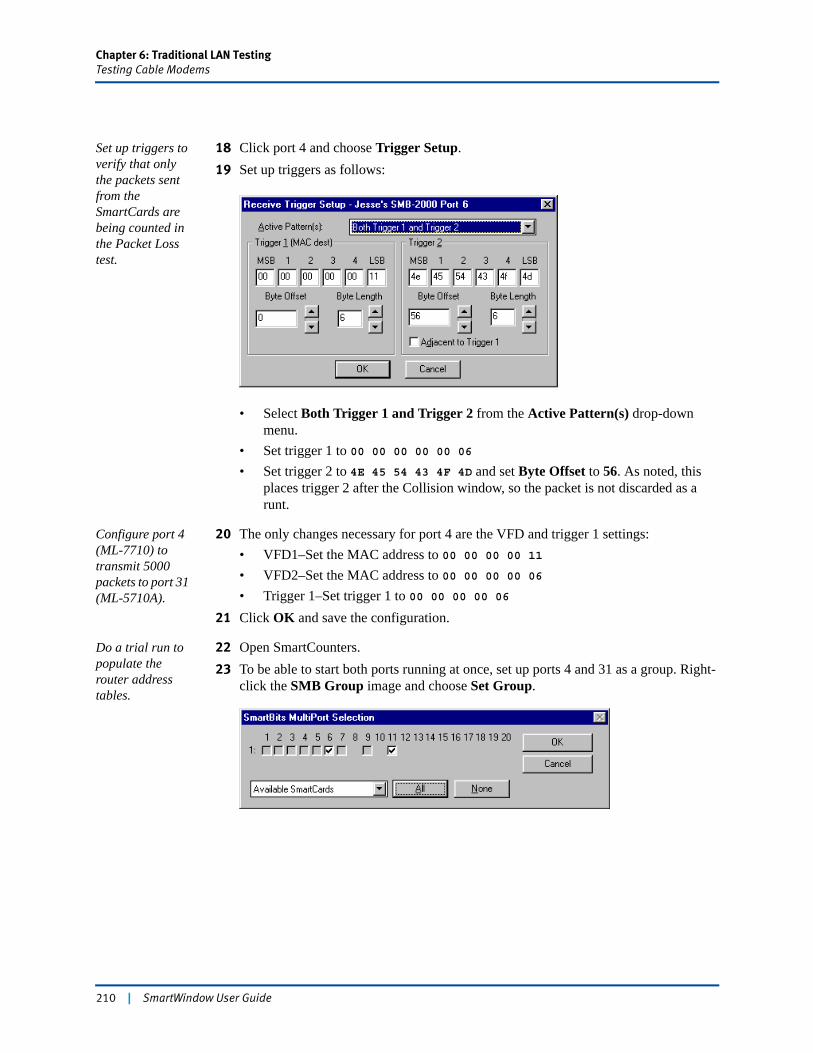
Chapter 6: Traditional LAN TestingTesting Cable Modems
Set up triggers to verify that only the packets sent from the SmartCards are being counted in the Packet Loss test.
18 Click port 4 and choose Trigger Setup.19 Set up triggers as follows:
• Select Both Trigger 1 and Trigger 2 from the Active Pattern(s) drop-down menu.
• Set trigger 1 to 00 00 00 00 00 06• Set trigger 2 to 4E 45 54 43 4F 4D and set Byte Offset to 56. As noted, this
places trigger 2 after the Collision window, so the packet is not discarded as a runt.
Configure port 4 (ML-7710) to transmit 5000 packets to port 31 (ML-5710A).
20 The only changes necessary for port 4 are the VFD and trigger 1 settings:• VFD1–Set the MAC address to 00 00 00 00 11• VFD2–Set the MAC address to 00 00 00 00 06• Trigger 1–Set trigger 1 to 00 00 00 00 06
21 Click OK and save the configuration.
Do a trial run to populate the router address tables.
22 Open SmartCounters.23 To be able to start both ports running at once, set up ports 4 and 31 as a group. Right-
click the SMB Group image and choose Set Group.
210 | SmartWindow User Guide
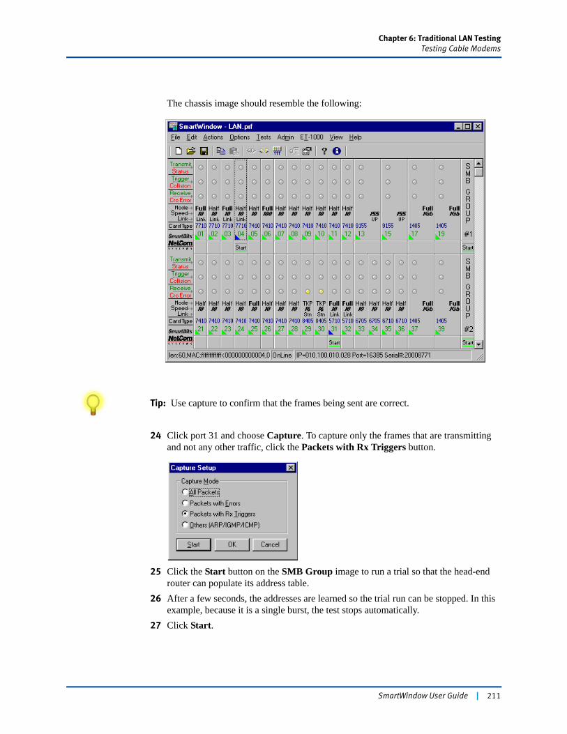
Chapter 6: Traditional LAN TestingTesting Cable Modems
The chassis image should resemble the following:
Tip: Use capture to confirm that the frames being sent are correct.
24 Click port 31 and choose Capture. To capture only the frames that are transmitting and not any other traffic, click the Packets with Rx Triggers button.
25 Click the Start button on the SMB Group image to run a trial so that the head-end router can populate its address table.
26 After a few seconds, the addresses are learned so the trial run can be stopped. In this example, because it is a single burst, the test stops automatically.
27 Click Start.
SmartWindow User Guide | 211
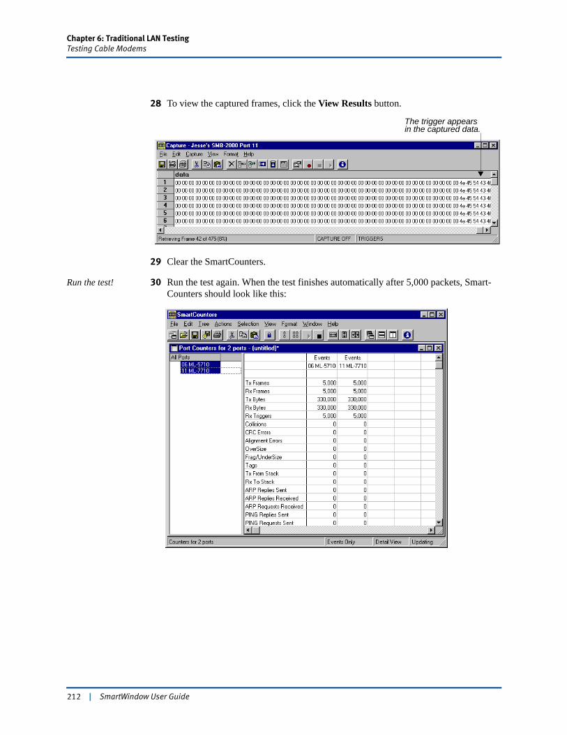
Chapter 6: Traditional LAN TestingTesting Cable Modems
28 To view the captured frames, click the View Results button.
29 Clear the SmartCounters.
Run the test! 30 Run the test again. When the test finishes automatically after 5,000 packets, Smart-Counters should look like this:
The trigger appearsin the captured data.
212 | SmartWindow User Guide
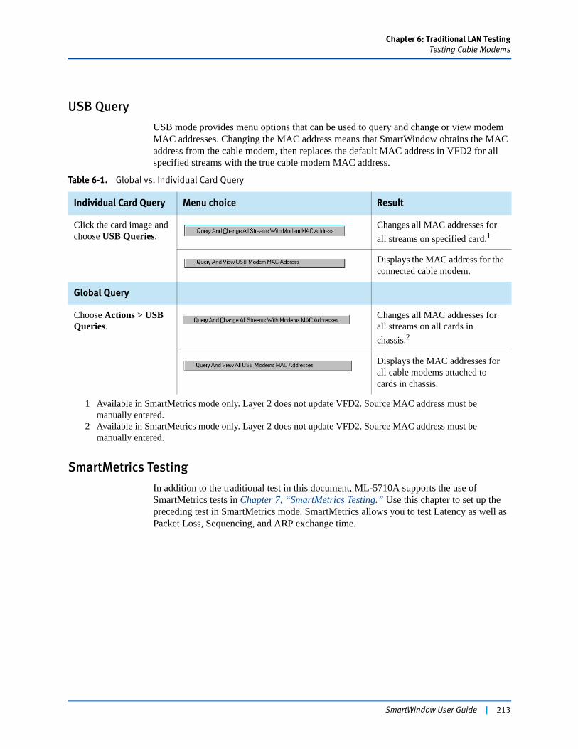
Chapter 6: Traditional LAN TestingTesting Cable Modems
USB Query
USB mode provides menu options that can be used to query and change or view modem MAC addresses. Changing the MAC address means that SmartWindow obtains the MAC address from the cable modem, then replaces the default MAC address in VFD2 for all specified streams with the true cable modem MAC address.
SmartMetrics Testing
In addition to the traditional test in this document, ML-5710A supports the use of SmartMetrics tests in Chapter 7, “SmartMetrics Testing.” Use this chapter to set up the preceding test in SmartMetrics mode. SmartMetrics allows you to test Latency as well as Packet Loss, Sequencing, and ARP exchange time.
Table 6-1. Global vs. Individual Card Query
Individual Card Query Menu choice Result
Click the card image and choose USB Queries.
Changes all MAC addresses for all streams on specified card.1
Displays the MAC address for the connected cable modem.
Global Query
Choose Actions > USB Queries.
Changes all MAC addresses for all streams on all cards in chassis.2
Displays the MAC addresses for all cable modems attached to cards in chassis.
1 Available in SmartMetrics mode only. Layer 2 does not update VFD2. Source MAC address must be manually entered.
2 Available in SmartMetrics mode only. Layer 2 does not update VFD2. Source MAC address must be manually entered.
SmartWindow User Guide | 213

Chapter 6: Traditional LAN TestingTesting VLAN Tagging Across a Gigabit Uplink
Testing VLAN Tagging Across a Gigabit UplinkUsing six ML-7710 SmartCards and one GX-1420B SmartCard, a series of meaningful tests on 10/100Mbps switches with a copper Gigabit port can be performed. These SmartCards working in traditional mode can test the DUT VLAN capabilities for:
• Flooding and leakage• Packet loss.
Figure 6-6. VLAN Topology
Note: This test setup uses the ML-7710A and GX-1420B SmartCards. Additional SmartCards that support this test include the following:
• One LAN-3100A can be substituted for the ML-7710, and one LAN-3201B/C can be substituted for the GX-1420B.
• An SX-7410/B can be substituted for the ML-7710.
R = Red VLANB = Blue VLANG = Green VLAN
1000
1000
10/100
10/100
10/100
RR
B
G
BB, G, R
B, G, R
12
Tagged port
Untagged ports
Tagged ports
Untagged
DUT 1 DUT 2
10/100 ports
G
214 | SmartWindow User Guide
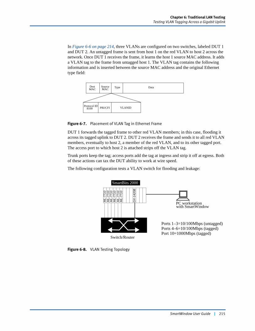
Chapter 6: Traditional LAN TestingTesting VLAN Tagging Across a Gigabit Uplink
In Figure 6-6 on page 214, three VLANs are configured on two switches, labeled DUT 1 and DUT 2. An untagged frame is sent from host 1 on the red VLAN to host 2 across the network. Once DUT 1 receives the frame, it learns the host 1 source MAC address. It adds a VLAN tag to the frame from untagged host 1. The VLAN tag contains the following information and is inserted between the source MAC address and the original Ethernet type field:
Figure 6-7. Placement of VLAN Tag in Ethernet Frame
DUT 1 forwards the tagged frame to other red VLAN members; in this case, flooding it across its tagged uplink to DUT 2. DUT 2 receives the frame and sends it to all red VLAN members, eventually to host 2, a member of the red VLAN, and to its other tagged port. The access port to which host 2 is attached strips off the VLAN tag.
Trunk ports keep the tag; access ports add the tag at ingress and strip it off at egress. Both of these actions can tax the DUT ability to work at wire speed.
The following configuration tests a VLAN switch for flooding and leakage:
Figure 6-8. VLAN Testing Topology
MACType Data
Protocol ID VLANIDPRI/CFI
MACSourceDest
8100
PC workstationwith SmartWindow
Switch/Router
SmartBits 2000
Ports 1–3=10/100Mbps (untagged)Ports 4–6=10/100Mbps (tagged)Port 10=1000Mbps (tagged)
GX
-142
0B
ML-
7710
ML-
7710
ML-
7710
ML-
7710
ML-
7710
ML-
7710
SmartWindow User Guide | 215
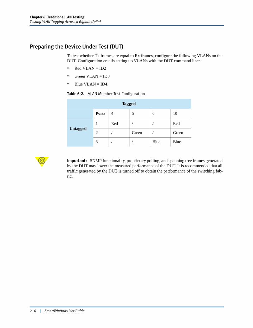
Chapter 6: Traditional LAN TestingTesting VLAN Tagging Across a Gigabit Uplink
Preparing the Device Under Test (DUT)
To test whether Tx frames are equal to Rx frames, configure the following VLANs on the DUT. Configuration entails setting up VLANs with the DUT command line:
• Red VLAN = ID2
• Green VLAN = ID3
• Blue VLAN = ID4.
Important: SNMP functionality, proprietary polling, and spanning tree frames generated by the DUT may lower the measured performance of the DUT. It is recommended that all traffic generated by the DUT is turned off to obtain the performance of the switching fab-ric.
Table 6-2. VLAN Member Test Configuration
Tagged
Ports 4 5 6 10
Untagged1 Red / / Red
2 / Green / Green
3 / / Blue Blue
216 | SmartWindow User Guide
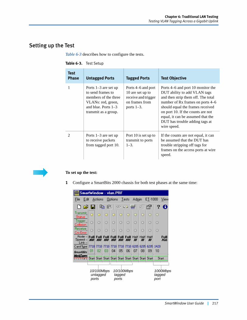
Chapter 6: Traditional LAN TestingTesting VLAN Tagging Across a Gigabit Uplink
Setting up the Test
Table 6-3 describes how to configure the tests.
To set up the test:
1 Configure a SmartBits 2000 chassis for both test phases at the same time:
Table 6-3. Test Setup
Test Phase Untagged Ports Tagged Ports Test Objective
1 Ports 1–3 are set up to send frames to members of the three VLANs: red, green, and blue. Ports 1–3 transmit as a group.
Ports 4–6 and port 10 are set up to receive and trigger on frames from ports 1–3.
Ports 4–6 and port 10 monitor the DUT ability to add VLAN tags and then strip them off. The total number of Rx frames on ports 4–6 should equal the frames received on port 10. If the counts are not equal, it can be assumed that the DUT has trouble adding tags at wire speed.
2 Ports 1–3 are set up to receive packets from tagged port 10.
Port 10 is set up to transmit to ports 1–3.
If the counts are not equal, it can be assumed that the DUT has trouble stripping off tags for frames on the access ports at wire speed.
10/100Mbps
ports untagged
10/100Mbps
ports tagged
1000Mbpstaggedport
SmartWindow User Guide | 217
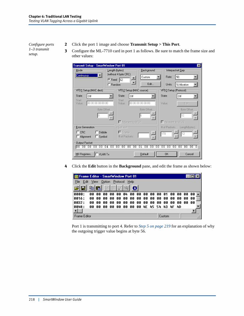
Chapter 6: Traditional LAN TestingTesting VLAN Tagging Across a Gigabit Uplink
Configure ports 1–3 transmit setup.
2 Click the port 1 image and choose Transmit Setup > This Port.3 Configure the ML-7710 card in port 1 as follows. Be sure to match the frame size and
other values:
4 Click the Edit button in the Background pane, and edit the frame as shown below:
Port 1 is transmitting to port 4. Refer to Step 5 on page 219 for an explanation of why the outgoing trigger value begins at byte 56.
218 | SmartWindow User Guide
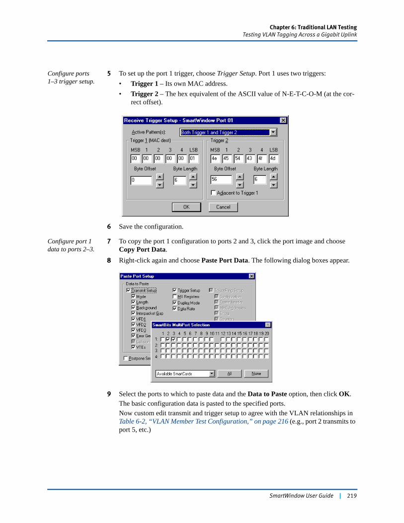
Chapter 6: Traditional LAN TestingTesting VLAN Tagging Across a Gigabit Uplink
Configure ports 1–3 trigger setup.
5 To set up the port 1 trigger, choose Trigger Setup. Port 1 uses two triggers:• Trigger 1 – Its own MAC address.• Trigger 2 – The hex equivalent of the ASCII value of N-E-T-C-O-M (at the cor-
rect offset).
6 Save the configuration.
Configure port 1 data to ports 2–3.
7 To copy the port 1 configuration to ports 2 and 3, click the port image and choose Copy Port Data.
8 Right-click again and choose Paste Port Data. The following dialog boxes appear.
9 Select the ports to which to paste data and the Data to Paste option, then click OK.The basic configuration data is pasted to the specified ports.Now custom edit transmit and trigger setup to agree with the VLAN relationships in Table 6-2, “VLAN Member Test Configuration,” on page 216 (e.g., port 2 transmits to port 5, etc.)
SmartWindow User Guide | 219
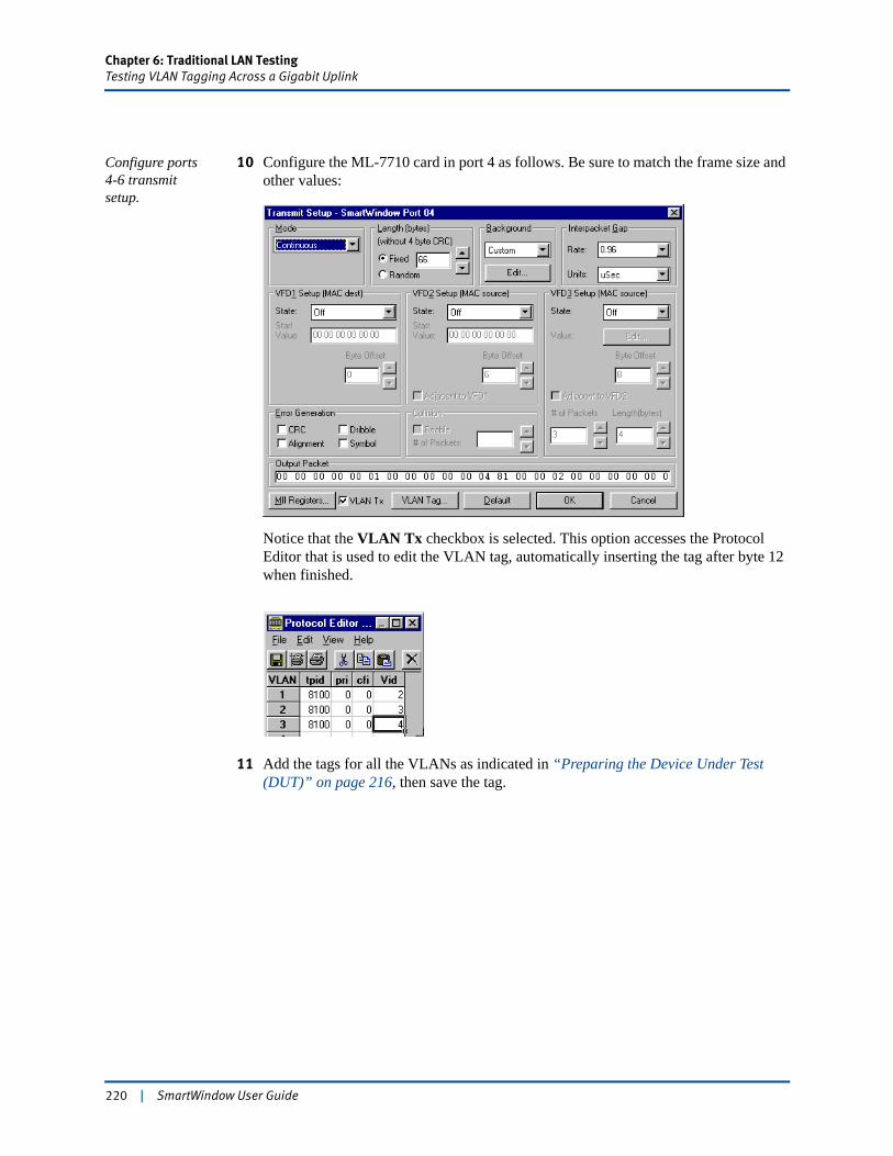
Chapter 6: Traditional LAN TestingTesting VLAN Tagging Across a Gigabit Uplink
Configure ports 4-6 transmit setup.
10 Configure the ML-7710 card in port 4 as follows. Be sure to match the frame size and other values:
Notice that the VLAN Tx checkbox is selected. This option accesses the Protocol Editor that is used to edit the VLAN tag, automatically inserting the tag after byte 12 when finished.
11 Add the tags for all the VLANs as indicated in “Preparing the Device Under Test (DUT)” on page 216, then save the tag.
220 | SmartWindow User Guide
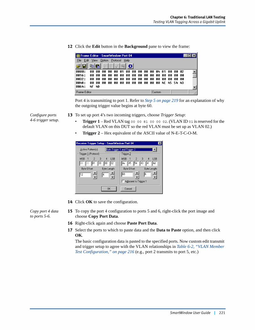
Chapter 6: Traditional LAN TestingTesting VLAN Tagging Across a Gigabit Uplink
12 Click the Edit button in the Background pane to view the frame:
Port 4 is transmitting to port 1. Refer to Step 5 on page 219 for an explanation of why the outgoing trigger value begins at byte 60.
Configure ports 4-6 trigger setup.
13 To set up port 4’s two incoming triggers, choose Trigger Setup:• Trigger 1 – Red VLAN tag 00 00 81 00 00 02. (VLAN ID 01 is reserved for the
default VLAN on this DUT so the red VLAN must be set up as VLAN 02.)• Trigger 2 – Hex equivalent of the ASCII value of N-E-T-C-O-M.
14 Click OK to save the configuration.
Copy port 4 data to ports 5-6.
15 To copy the port 4 configuration to ports 5 and 6, right-click the port image and choose Copy Port Data.
16 Right-click again and choose Paste Port Data.17 Select the ports to which to paste data and the Data to Paste option, and then click
OK.The basic configuration data is pasted to the specified ports. Now custom edit transmit and trigger setup to agree with the VLAN relationships in Table 6-2, “VLAN Member Test Configuration,” on page 216 (e.g., port 2 transmits to port 5, etc.)
SmartWindow User Guide | 221
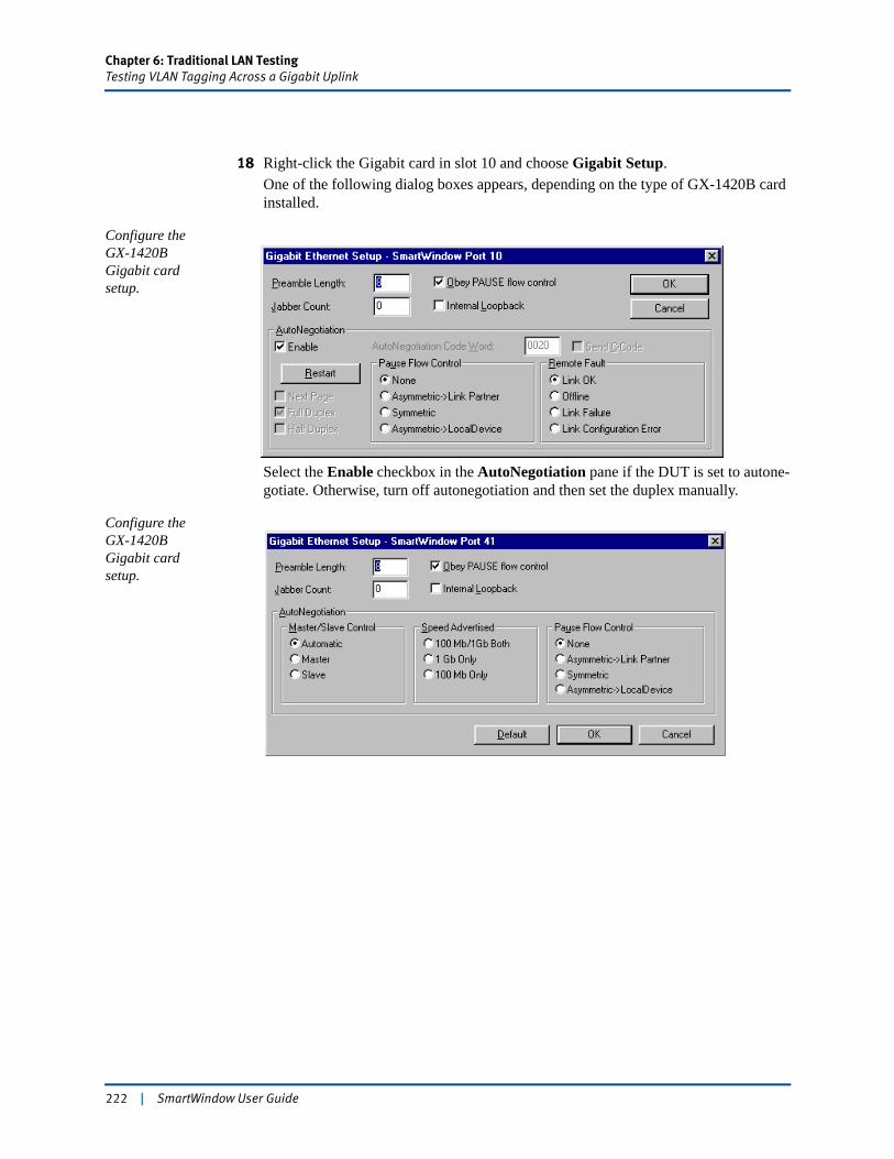
Chapter 6: Traditional LAN TestingTesting VLAN Tagging Across a Gigabit Uplink
18 Right-click the Gigabit card in slot 10 and choose Gigabit Setup.One of the following dialog boxes appears, depending on the type of GX-1420B card installed.
Configure the GX-1420B Gigabit card setup.
Select the Enable checkbox in the AutoNegotiation pane if the DUT is set to autone-gotiate. Otherwise, turn off autonegotiation and then set the duplex manually.
Configure the GX-1420B Gigabit card setup.
222 | SmartWindow User Guide
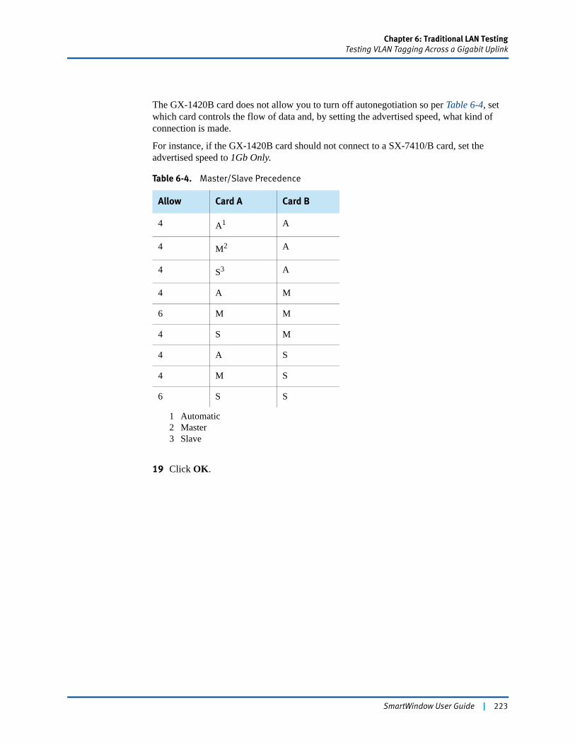
Chapter 6: Traditional LAN TestingTesting VLAN Tagging Across a Gigabit Uplink
The GX-1420B card does not allow you to turn off autonegotiation so per Table 6-4, set which card controls the flow of data and, by setting the advertised speed, what kind of connection is made.
For instance, if the GX-1420B card should not connect to a SX-7410/B card, set the advertised speed to 1Gb Only.
19 Click OK.
Table 6-4. Master/Slave Precedence
Allow Card A Card B
4 A1
1 Automatic
A
4 M2
2 Master
A
4 S3
3 Slave
A
4 A M
6 M M
4 S M
4 A S
4 M S
6 S S
SmartWindow User Guide | 223
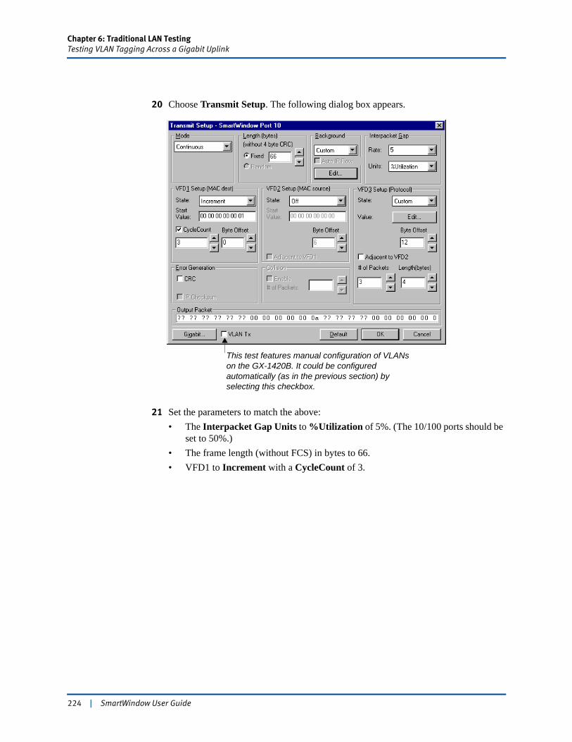
Chapter 6: Traditional LAN TestingTesting VLAN Tagging Across a Gigabit Uplink
20 Choose Transmit Setup. The following dialog box appears.
21 Set the parameters to match the above:• The Interpacket Gap Units to %Utilization of 5%. (The 10/100 ports should be
set to 50%.)• The frame length (without FCS) in bytes to 66.• VFD1 to Increment with a CycleCount of 3.
This test features manual configuration of VLANs on the GX-1420B. It could be configured automatically (as in the previous section) by selecting this checkbox.
224 | SmartWindow User Guide
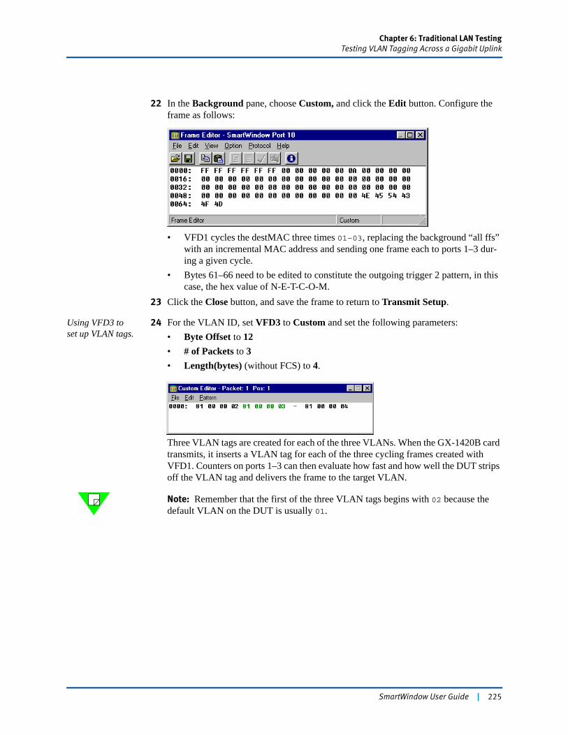
Chapter 6: Traditional LAN TestingTesting VLAN Tagging Across a Gigabit Uplink
22 In the Background pane, choose Custom, and click the Edit button. Configure the frame as follows:
• VFD1 cycles the destMAC three times 01–03, replacing the background “all ffs” with an incremental MAC address and sending one frame each to ports 1–3 dur-ing a given cycle.
• Bytes 61–66 need to be edited to constitute the outgoing trigger 2 pattern, in this case, the hex value of N-E-T-C-O-M.
23 Click the Close button, and save the frame to return to Transmit Setup.
Using VFD3 to set up VLAN tags.
24 For the VLAN ID, set VFD3 to Custom and set the following parameters:• Byte Offset to 12• # of Packets to 3• Length(bytes) (without FCS) to 4.
Three VLAN tags are created for each of the three VLANs. When the GX-1420B card transmits, it inserts a VLAN tag for each of the three cycling frames created with VFD1. Counters on ports 1–3 can then evaluate how fast and how well the DUT strips off the VLAN tag and delivers the frame to the target VLAN.
Note: Remember that the first of the three VLAN tags begins with 02 because the default VLAN on the DUT is usually 01.
SmartWindow User Guide | 225
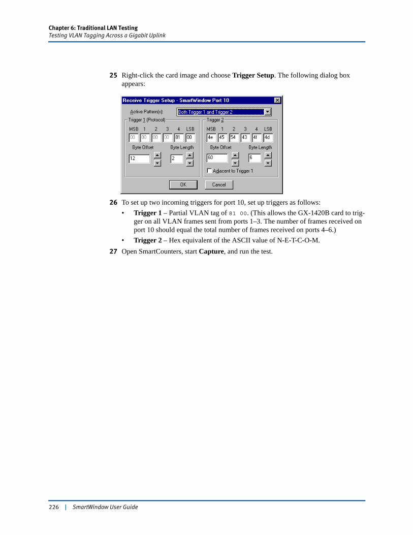
Chapter 6: Traditional LAN TestingTesting VLAN Tagging Across a Gigabit Uplink
25 Right-click the card image and choose Trigger Setup. The following dialog box appears:
26 To set up two incoming triggers for port 10, set up triggers as follows:• Trigger 1 – Partial VLAN tag of 81 00. (This allows the GX-1420B card to trig-
ger on all VLAN frames sent from ports 1–3. The number of frames received on port 10 should equal the total number of frames received on ports 4–6.)
• Trigger 2 – Hex equivalent of the ASCII value of N-E-T-C-O-M.27 Open SmartCounters, start Capture, and run the test.
226 | SmartWindow User Guide
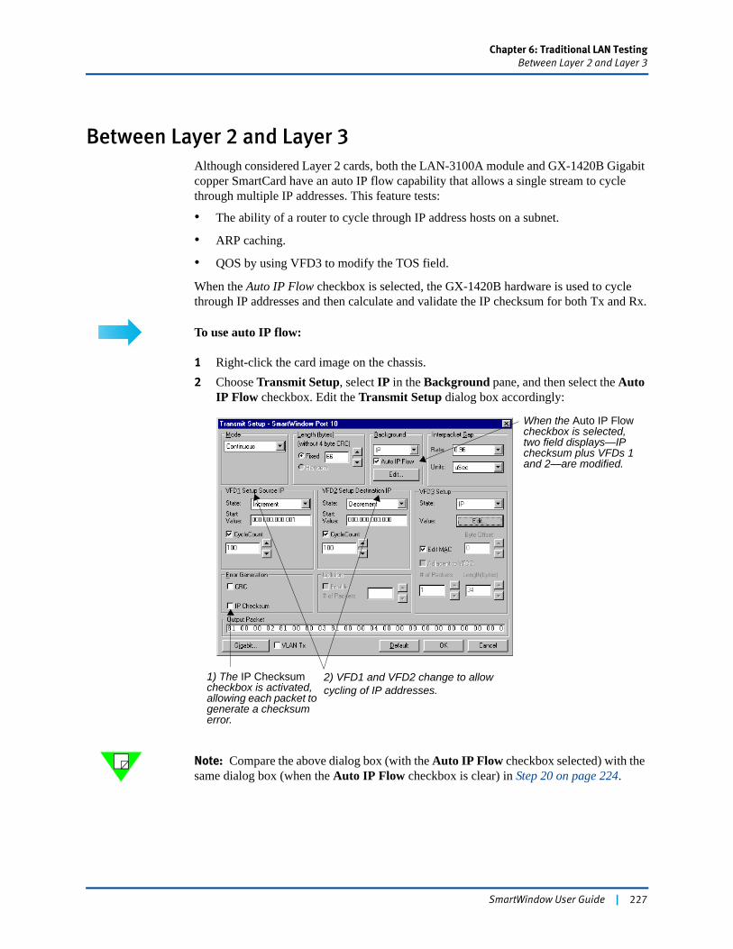
Chapter 6: Traditional LAN TestingBetween Layer 2 and Layer 3
Between Layer 2 and Layer 3Although considered Layer 2 cards, both the LAN-3100A module and GX-1420B Gigabit copper SmartCard have an auto IP flow capability that allows a single stream to cycle through multiple IP addresses. This feature tests:
• The ability of a router to cycle through IP address hosts on a subnet.
• ARP caching.
• QOS by using VFD3 to modify the TOS field.
When the Auto IP Flow checkbox is selected, the GX-1420B hardware is used to cycle through IP addresses and then calculate and validate the IP checksum for both Tx and Rx.
To use auto IP flow:
1 Right-click the card image on the chassis.2 Choose Transmit Setup, select IP in the Background pane, and then select the Auto
IP Flow checkbox. Edit the Transmit Setup dialog box accordingly:
Note: Compare the above dialog box (with the Auto IP Flow checkbox selected) with the same dialog box (when the Auto IP Flow checkbox is clear) in Step 20 on page 224.
When the Auto IP Flow checkbox is selected, two field displays—IP checksum plus VFDs 1 and 2—are modified.
2) VFD1 and VFD2 change to allow cycling of IP addresses.
1) The IP Checksum checkbox is activated, allowing each packet to generate a checksum error.
SmartWindow User Guide | 227
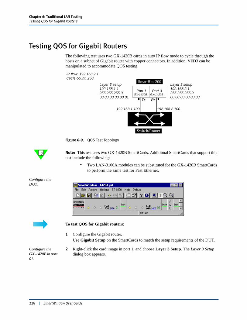
Chapter 6: Traditional LAN TestingTesting QOS for Gigabit Routers
Testing QOS for Gigabit RoutersThe following test uses two GX-1420B cards in auto IP flow mode to cycle through the hosts on a subnet of Gigabit router with copper connectors. In addition, VFD3 can be manipulated to accommodate QOS testing.
Figure 6-9. QOS Test Topology
Note: This test uses two GX-1420B SmartCards. Additional SmartCards that support this test include the following:
• Two LAN-3100A modules can be substituted for the GX-1420B SmartCards to perform the same test for Fast Ethernet.
Configure the DUT.
To test QOS for Gigabit routers:
1 Configure the Gigabit router.Use Gigabit Setup on the SmartCards to match the setup requirements of the DUT.
Configure the GX-1420B in port 01.
2 Right-click the card image in port 1, and choose Layer 3 Setup. The Layer 3 Setup dialog box appears.
Switch/Router
SmartBits 200
GX-1420B GX-1420B
192.168.1.100 192.168.2.100
Tx Rx
Layer 3 setup192.168.1.1255.255.255.000 00 00 00 00 01
Layer 3 setup192.168.2.1255.255.255.000 00 00 00 00 03
Port 1 Port 3
IP flow: 192.168.2.1Cycle count: 250
228 | SmartWindow User Guide
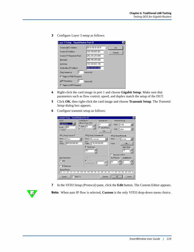
Chapter 6: Traditional LAN TestingTesting QOS for Gigabit Routers
3 Configure Layer 3 setup as follows:
4 Right-click the card image in port 1 and choose Gigabit Setup. Make sure that parameters such as flow control, speed, and duplex match the setup of the DUT.
5 Click OK, then right-click the card image and choose Transmit Setup. The Transmit Setup dialog box appears.
6 Configure transmit setup as follows:
7 In the VFD3 Setup (Protocol) pane, click the Edit button. The Custom Editor appears.
Note: When auto IP flow is selected, Custom is the only VFD3 drop-down menu choice.
SmartWindow User Guide | 229

Chapter 6: Traditional LAN TestingTesting QOS for Gigabit Routers
8 For this example, configure ten 1-byte values to replace the background values in the TOS field as each flow cycles through.
Note: For the ten packets that make up a simulated cycle, VFD3 substitutes the following values:• One 64 to simulate video/voice frames• Four 32s to simulate database frames• Five 0s to simulate HTTP frames.Higher priority traffic should experience lower latency, even though (in this test) no packet loss is expected. A variation of this test might be to use an ML-7710 on the receiving end and then slightly overbook it by setting the GX-1420B to transmit at 11% of line rate.
9 Close all dialog boxes and save the configuration.
Configure the GX-1420B in port 03.
10 Using the information for port 03 in Figure 6-9 on page 228, configure theGX-1420B in port 03.
Note: You need to configure Gigabit setup, Layer 3 setup, and transmit setup. Do this quickly by copying, then pasting the transmit setup data for port 01 to port 03.
11 Right-click port 01, then choose Copy Port Data. A message states that the data has been copied.
12 Right-click port 03, then choose Paste Port Data.The following dialog box appears.
13 Check the port 03 checkbox.
230 | SmartWindow User Guide
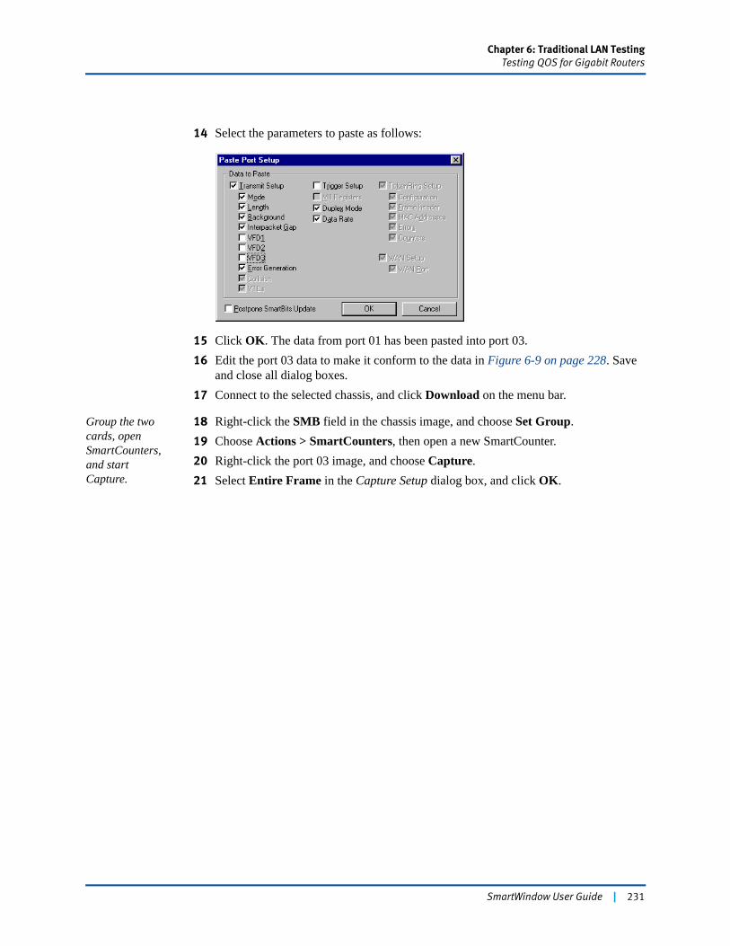
Chapter 6: Traditional LAN TestingTesting QOS for Gigabit Routers
14 Select the parameters to paste as follows:
15 Click OK. The data from port 01 has been pasted into port 03.16 Edit the port 03 data to make it conform to the data in Figure 6-9 on page 228. Save
and close all dialog boxes.17 Connect to the selected chassis, and click Download on the menu bar.
Group the two cards, open SmartCounters, and start Capture.
18 Right-click the SMB field in the chassis image, and choose Set Group.19 Choose Actions > SmartCounters, then open a new SmartCounter.20 Right-click the port 03 image, and choose Capture.21 Select Entire Frame in the Capture Setup dialog box, and click OK.
SmartWindow User Guide | 231

Chapter 6: Traditional LAN TestingTesting QOS for Gigabit Routers
Run the test and check the results!
22 Click the group Start button.The test is configured to send 500 frames.
23 View SmartCounters to verify that good frames were sent and received.
232 | SmartWindow User Guide
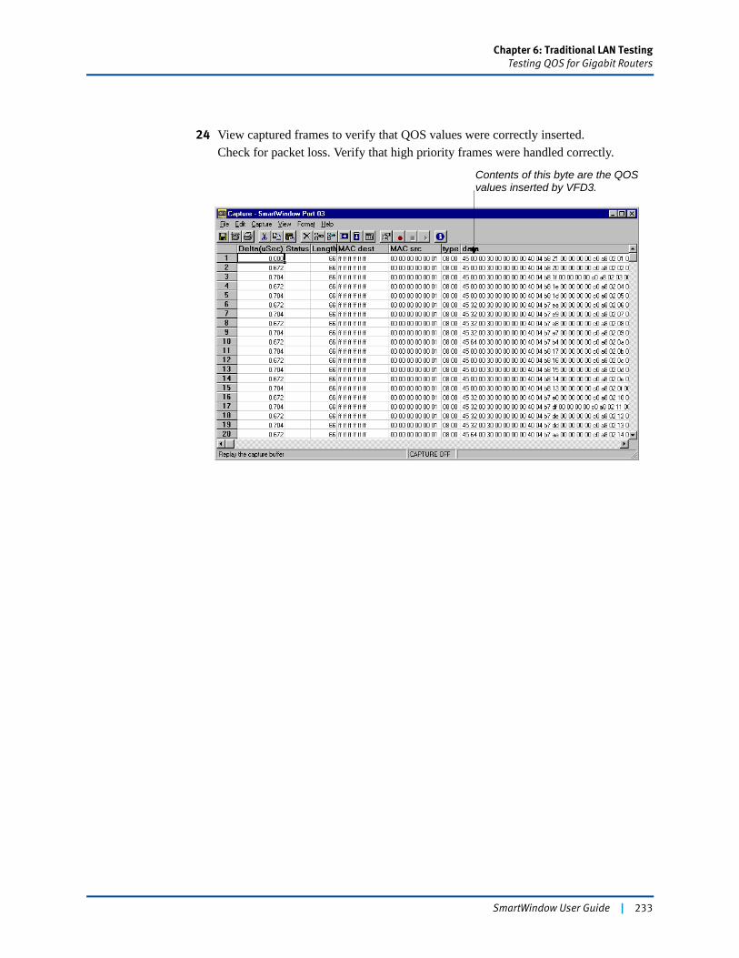
Chapter 6: Traditional LAN TestingTesting QOS for Gigabit Routers
24 View captured frames to verify that QOS values were correctly inserted.Check for packet loss. Verify that high priority frames were handled correctly.
Contents of this byte are the QOSvalues inserted by VFD3.
SmartWindow User Guide | 233

234 | SmartWindow User Guide

Chapter 7
SmartMetrics Testing
SmartWindow is a highly effective tool for both traditional and custom tests. SmartMetrics SmartCards such as the ML-5710A and ML-7710 can simulate up to 1,000 hosts per port, sending varied or uniform traffic to the Layer 3 switch. They can fully characterize the switch for both Layer 2 and Layer 3. The LAN-3101A/B SmartMetrics modules, with six ports per module, provide even higher traffic density for extended testing. A TeraMetrics module like the LAN-3321A offers full SmartMetrics capabilities along with the TeraMetrics open architecture. All these cards enable you to perform a range of tests for Layer 3 functions—including SmartMetrics tests—and allow testing of complex protocol sensitive application and systems scenarios.
In this chapter...
• Layer 3 Switching . . . . 236
• Required Steps for SmartMetrics (Layer 3) Testing . . . . 238
• Test Using the LAN-3321A TeraMetrics Module . . . . 246
• Testing Using ML-7710 SmartMetrics SmartCards . . . . 265
• Setting Multiple Streams per Card . . . . 273
• About SmartMetrics . . . . 278
• How to Run SmartMetrics Tests . . . . 284
• How to Optimize 16-bit Latency Testing . . . . 289
• SmartMetrics 16-bit Tests . . . . 290
• Other SmartMetrics Tests . . . . 297
• SmartMetrics Test Results . . . . 306
• Detailed Tracking and Statistical Results . . . . 308
SmartWindow User Guide | 235
Chapter 7: SmartMetrics TestingLayer 3 Switching
Layer 3 SwitchingIn most cases, a Layer 3 switch is in fact a fast protocol-based router minus certain router functions. A Layer 3 switch typically works with only one or two protocols, performs at or close to wire speed, is good at keeping streaming packets in order, and makes routing decisions based on ASICs (unlike a router which is software-based).
The 10 Mbps, 100 Mbps, and Gigabit Ethernet Layer 3 switches are expected to operate at full line-rate at Layer 2 and furnish wire-speed IP routing at Layer 3 simultaneously on all ports with zero packet loss and extremely low latency.
Test MethodologyThe SmartWindow tests and results that demonstrate the performance capability of the switch include the following topics:
• 20+ counters (transmit and receive packets and bytes, packet loss, triggers, tags, collisions, errors, plus ARP and ping counters)
• Sequence tracking data
• Latency distribution data
• Latency over time data.
Note: The types of tests are dependent on the hardware and version level of SmartWindow used. Refer to the specific description of the test(s) for qualifications and details.
About StreamsIt is essential to understand SmartMetrics streams, which provide the basis for using the traffic and test capabilities of SmartMetrics cards and modules.
Each stream, generated by its own Virtual Transmit Engine (VTE), represents a repeated packet template with the following characteristics:• Design that is able to set up traffic for testing Layer 2 (switching) or Layer 3 (routing).• A signature field in each packet contains its source and destination location, its
sequence in the traffic flow, and when it was sent and received.• Each stream has its own IP/MAC source and destination addresses, frame length
(without FCS), protocol or custom packet, IP gateway for routing, and statistics/histogram tracking capability.
• With IP, each stream also has ARP request and response ability.• The stream of one card typically transmits to the stream of another card, simulating
transmission from one host computer to a second host computer. Both can be on the same subnet or on different subnets.
• If 10 streams are defined, the 10 packets are transmitted in the order created, then re-cycled to transmit the next 10, until the transmission is stopped. If only one stream is created for a card, then the traffic is comprised of the one packet type.
236 | SmartWindow User Guide
Chapter 7: SmartMetrics TestingLayer 3 Switching
• An ML-7710 or LAN-3101A/B can transmit up to 1,000 streams per port and track statistics/histogram information on approximately 80,000 streams.
Older SmartCards, such as the SX-7410/B Ethernet SmartCard, are essentially packet blasters for hubs and switches. In contrast, each port on an ML-7710 SmartCard orLAN-3101A/B modules can generate the equivalent of 1,000 IP connections, condensed into a simple format for creating 1,000 streams that closely mimic real world traffic.
With the ML-7710 SmartCards, 20 cards can be placed into each SmartBits chassis, then four chassis can be stacked. With 80 cards, up to 80,000 streams can be simulated.
The LAN-3101A/B SmartMetrics module provides higher port density per chassis. A SmartBits 6000x can accommodate 12 LAN-3101A/B modules. With six ports per module, each chassis can generate traffic from 72 ports, enabling you to simulate up to 72,000 streams from each chassis.
LAN-33xxA TeraMetrics-based modules provide two ports per module. A SmartBits 6000x can accommodate 12 modules (24 ports total).
Hard Disk Requirements for Streams
The setup configuration for each stream requires 4.5 KB per stream per port. For each 1000 streams (one port), you may need to allocate 5 to 7 MB of hard drive. Multiply this by the number of ports in use and, if applicable, by the number of chassis.
In addition, in order to make histogram measurements, double the estimated hard drive requirement.
Example for ML-7710. If using ML-7710 SmartCards in four stacked SmartBits 2000 chassis, multiply the needed hard-disk space (5 to 7 MB) as follows:
• One port per card, 20 cards per SmartBits 2000 chassis
• Required: Approximately 6 MB per port
• Multiply by 20 cards = 120 MB of hard drive per test setup
• Multiply by 4 chassis = 480 MB of hard drive per test setup.
Example for LAN-3101A/B and related modules: If using LAN-3101A/B modules in a SmartBits 6000x chassis, multiply the needed hard-disk space (5 to 7 MB) as follows:
• Six ports per module, 12 modules per SmartBits 6000x chassis
• Multiply by 12 modules (72 ports) = 432 MB of hard drive per test setup.
Example for LAN-3301A and related modules: If using LAN-33xxA modules in a SmartBits 6000x chassis, multiply the needed hard-disk space (5 to 7 MB) as follows:
• Two ports per module, 12 modules per SmartBits 6000x chassis
• Multiply by 12 modules (24 ports) = 144 MB of hard drive per test setup.
SmartWindow User Guide | 237
Chapter 7: SmartMetrics TestingRequired Steps for SmartMetrics (Layer 3) Testing
Required Steps for SmartMetrics (Layer 3) TestingThe following sections apply to SmartMetrics testing using either of the card types shown as examples in this chapter (LAN-3301A and ML-7710). The sections describe the steps used to set up addresses (“Port Setup” below) and the use of ARP exchange (“Address Resolution Protocol (ARP)” on page 243). Both are necessary to route packets properly through attached devices.
Important: Testing routers requires some preparatory work. You must set up addresses and learn to use ARP exchange in the order presented before running any of the Smart-Metrics tests.
Port Setup
Use the Port Setup (SmartBits 600x/6000x chassis) or Layer 3 Setup (SmartBits 200/2000 chassis) dialog box to configure the required information before running SmartMetrics tests on a router and to control management frames per RFC-1944. You must provide the gateway of the router or the Layer 3 switch.
! Caution: Never select the Reply to all ARP requests checkbox (SmartBits 200/2000) or the Reply to All Requests checkbox (SmartBits 600x/6000x) when connected to a live network. SmartMetrics SmartCards automatically respond to ARP requests. Use these checkboxes/selections only for back-to-back testing. You can still automatically update the router ARP table for each stream by selecting Layer 3 Send ARP Requests from the SmartCard's popup menu or Layer 3 ARP from the Actions menu for the SmartBits 200/2000 chassis only.
To configure Layer 3 setup:
1 Open the card menu.• Click the SmartCard (SmartBits 200/2000 chassis) —or— • Click the port button (SmartBits 600x/6000x chassis).
2 Ensure that SmartMetric Mode is selected on the drop-down menu.3 Now set the Layer 3 address information.
a SmartBits 200/2000: Open the card menu again and select Layer 3 Setup.
238 | SmartWindow User Guide
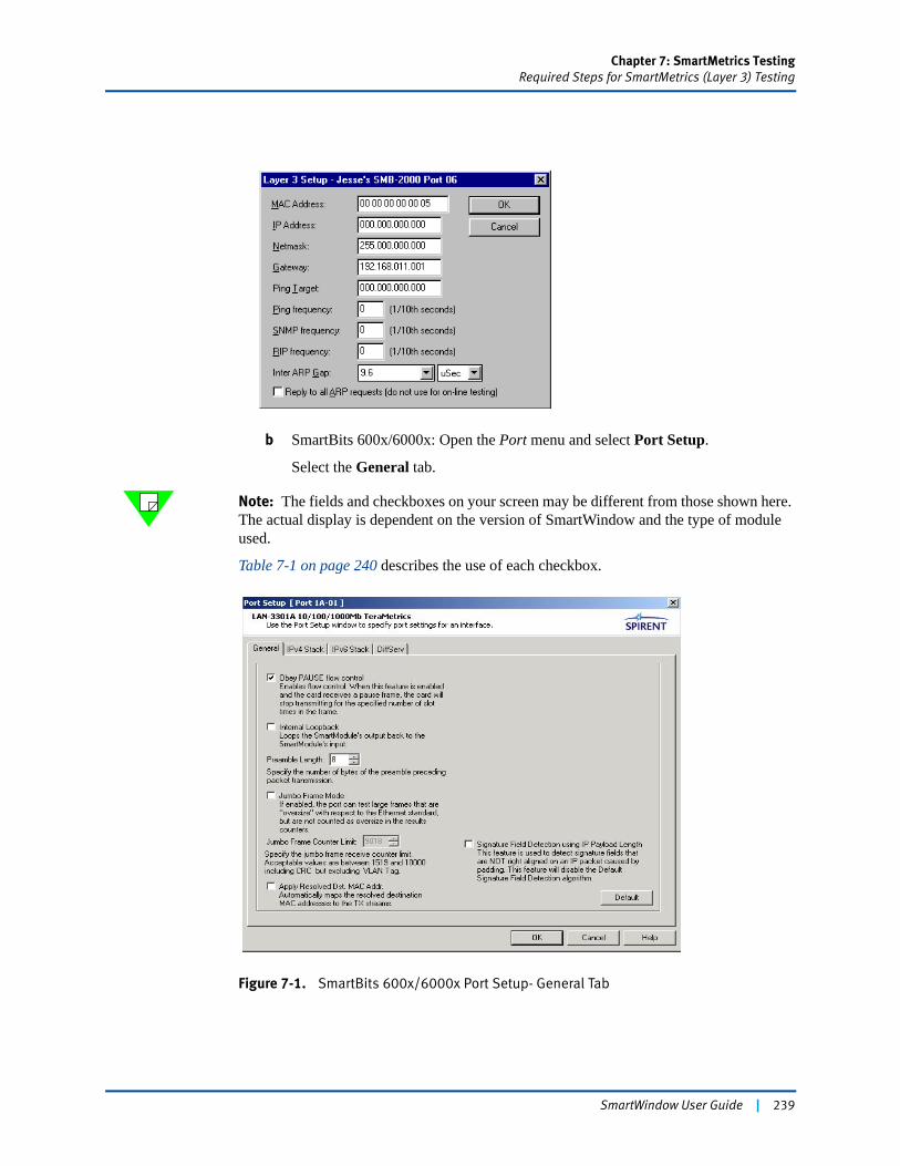
Chapter 7: SmartMetrics TestingRequired Steps for SmartMetrics (Layer 3) Testing
b SmartBits 600x/6000x: Open the Port menu and select Port Setup.
Select the General tab.
Note: The fields and checkboxes on your screen may be different from those shown here. The actual display is dependent on the version of SmartWindow and the type of module used.
Table 7-1 on page 240 describes the use of each checkbox.
Figure 7-1. SmartBits 600x/6000x Port Setup- General Tab
SmartWindow User Guide | 239
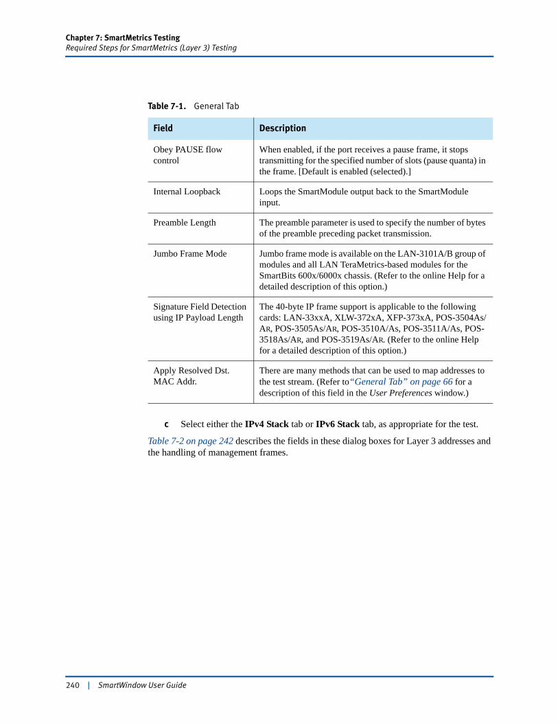
Chapter 7: SmartMetrics TestingRequired Steps for SmartMetrics (Layer 3) Testing
c Select either the IPv4 Stack tab or IPv6 Stack tab, as appropriate for the test.
Table 7-2 on page 242 describes the fields in these dialog boxes for Layer 3 addresses and the handling of management frames.
Table 7-1. General Tab
Field Description
Obey PAUSE flow control
When enabled, if the port receives a pause frame, it stops transmitting for the specified number of slots (pause quanta) in the frame. [Default is enabled (selected).]
Internal Loopback Loops the SmartModule output back to the SmartModule input.
Preamble Length The preamble parameter is used to specify the number of bytes of the preamble preceding packet transmission.
Jumbo Frame Mode Jumbo frame mode is available on the LAN-3101A/B group of modules and all LAN TeraMetrics-based modules for the SmartBits 600x/6000x chassis. (Refer to the online Help for a detailed description of this option.)
Signature Field Detection using IP Payload Length
The 40-byte IP frame support is applicable to the following cards: LAN-33xxA, XLW-372xA, XFP-373xA, POS-3504As/AR, POS-3505As/AR, POS-3510A/As, POS-3511A/As, POS-3518As/AR, and POS-3519As/AR. (Refer to the online Help for a detailed description of this option.)
Apply Resolved Dst. MAC Addr.
There are many methods that can be used to map addresses to the test stream. (Refer to“General Tab” on page 66 for a description of this field in the User Preferences window.)
240 | SmartWindow User Guide
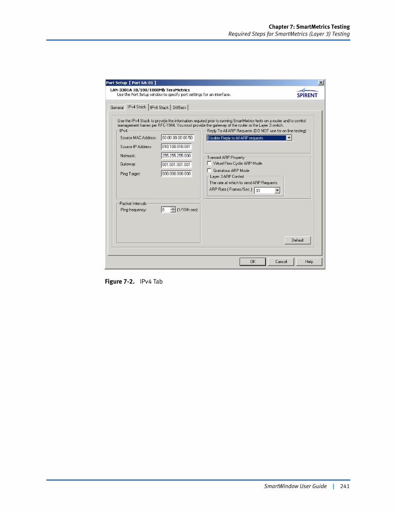
Chapter 7: SmartMetrics TestingRequired Steps for SmartMetrics (Layer 3) Testing
Figure 7-2. IPv4 Tab
SmartWindow User Guide | 241
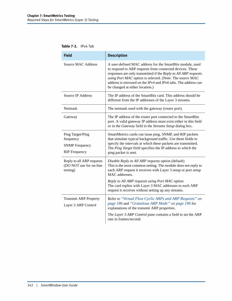
Chapter 7: SmartMetrics TestingRequired Steps for SmartMetrics (Layer 3) Testing
Table 7-2. IPv4 Tab
Field Description
Source MAC Address A user-defined MAC address for the SmartBits module, used to respond to ARP requests from connected devices. These responses are only transmitted if the Reply to All ARP requests using Port MAC option is selected. (Note: The source MAC address is mirrored on the IPv4 and IPv6 tabs. The address can be changed at either location.)
Source IP Address The IP address of the SmartBits card. This address should be different from the IP addresses of the Layer 3 streams.
Netmask The netmask used with the gateway (router port).
Gateway The IP address of the router port connected to the SmartBits port. A valid gateway IP address must exist either in this field or in the Gateway field in the Streams Setup dialog box.
Ping Target/Ping frequency
SNMP Frequency
RIP Frequency
SmartMetrics cards can issue ping, SNMP, and RIP packets that simulate typical background traffic. Use these fields to specify the intervals at which these packets are transmitted. The Ping Target field specifies the IP address to which the ping packet is sent.
Reply to all ARP requests (DO NOT use for on-line testing)
Disable Reply to All ARP requests option (default)This is the most common setting. The module does not reply to each ARP request it receives with Layer 3 setup or port setup MAC addresses.
Reply to All ARP requests using Port MAC optionThe card replies with Layer 3 MAC addresses to each ARP request it receives without setting up any streams.
Transmit ARP Property
Layer 3 ARP Control
Refer to “Virtual Flow Cyclic ARPs and ARP Requests” on page 186 and “Gratuitous ARP Mode” on page 196 for explanations of the transmit ARP properties.
The Layer 3 ARP Control pane contains a field to set the ARP rate in frames/second.
242 | SmartWindow User Guide
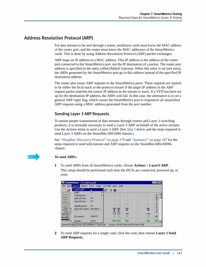
Chapter 7: SmartMetrics TestingRequired Steps for SmartMetrics (Layer 3) Testing
Address Resolution Protocol (ARP)
For data streams to be sent through a router, multilayer cards must know the MAC address of the router port, and the router must know the MAC addresses of the SmartMetrics cards. This is done by using Address Resolution Protocol (ARP) packet exchanges.
ARP maps an IP address to a MAC address. This IP address is the address of the router port connected to the SmartMetrics port, not the IP destination of a packet. The router port address is specified in the entry called Default Gateway. When this entry is set (not zero), the ARPs generated by the SmartMetrics port go to this address instead of the specified IP destination address.
The router also issues ARP requests to the SmartMetrics ports. These requests are replied to by either the local stack or the protocol stream if the target IP address in the ARP request packet matches the source IP address in the stream or stack. If a VFD has been set up for the destination IP address, the ARPs will fail. In this case, the alternative is to set a general ARP reply flag, which causes the SmartMetrics port to respond to all unsatisfied ARP requests using a MAC address generated from the port number.
Sending Layer 3 ARP Requests
To ensure proper transmission of data streams through routers and Layer 3 switching products, it is normally necessary to send a Layer 3 ARP on behalf of the active streams. Use the Actions menu to send a Layer 3 ARP. (See Step 1 below and the steps required to send Layer 3 ARPs on the SmartBits 200/2000 chassis.)
See “Neighbor Discovery Protocol” on page 179 and “Summary” on page 187 for the steps required to send solicitations and ARP requests on the SmartBits 600x/6000x chassis.
To send ARPs:
1 To send ARPs from all SmartMetrics cards, choose Actions > Layer3 ARP.This setup should be performed each time the DUTs are connected, powered up, or reset.
2 To send ARP requests for a single card, click the card, then choose Layer 3 Send ARP Requests.
SmartWindow User Guide | 243
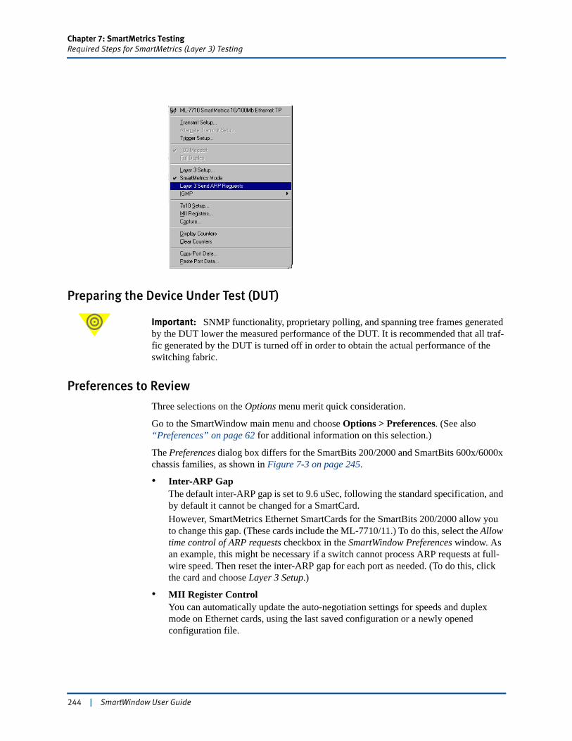
Chapter 7: SmartMetrics TestingRequired Steps for SmartMetrics (Layer 3) Testing
Preparing the Device Under Test (DUT)
Important: SNMP functionality, proprietary polling, and spanning tree frames generated by the DUT lower the measured performance of the DUT. It is recommended that all traf-fic generated by the DUT is turned off in order to obtain the actual performance of the switching fabric.
Preferences to Review
Three selections on the Options menu merit quick consideration.
Go to the SmartWindow main menu and choose Options > Preferences. (See also “Preferences” on page 62 for additional information on this selection.)
The Preferences dialog box differs for the SmartBits 200/2000 and SmartBits 600x/6000x chassis families, as shown in Figure 7-3 on page 245.
• Inter-ARP GapThe default inter-ARP gap is set to 9.6 uSec, following the standard specification, and by default it cannot be changed for a SmartCard.However, SmartMetrics Ethernet SmartCards for the SmartBits 200/2000 allow you to change this gap. (These cards include the ML-7710/11.) To do this, select the Allow time control of ARP requests checkbox in the SmartWindow Preferences window. As an example, this might be necessary if a switch cannot process ARP requests at full-wire speed. Then reset the inter-ARP gap for each port as needed. (To do this, click the card and choose Layer 3 Setup.)
• MII Register ControlYou can automatically update the auto-negotiation settings for speeds and duplex mode on Ethernet cards, using the last saved configuration or a newly opened configuration file.
244 | SmartWindow User Guide
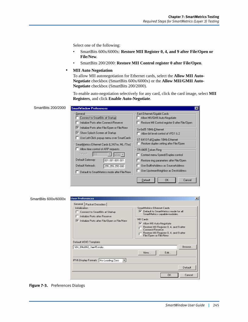
Chapter 7: SmartMetrics TestingRequired Steps for SmartMetrics (Layer 3) Testing
Select one of the following:• SmartBits 600x/6000x: Restore MII Register 0, 4, and 9 after File/Open or
File/New.• SmartBits 200/2000: Restore MII Control register 0 after File/Open.
• MII Auto NegotiationTo allow MII autonegotiation for Ethernet cards, select the Allow MII Auto-Negotiate checkbox (SmartBits 600x/6000x) or the Allow MII/GMII Auto-Negotiate checkbox (SmartBits 200/2000).
To enable auto-negotiation selectively for any card, click the card image, select MII Registers, and click Enable Auto-Negotiate.
Figure 7-3. Preferences Dialogs
SmartBits 200/2000
SmartBits 600x/6000x
SmartWindow User Guide | 245
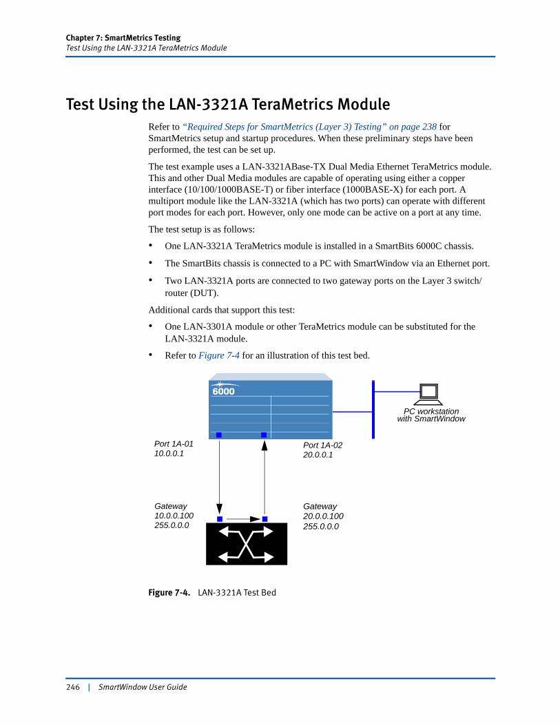
Chapter 7: SmartMetrics TestingTest Using the LAN-3321A TeraMetrics Module
Test Using the LAN-3321A TeraMetrics ModuleRefer to “Required Steps for SmartMetrics (Layer 3) Testing” on page 238 for SmartMetrics setup and startup procedures. When these preliminary steps have been performed, the test can be set up.
The test example uses a LAN-3321ABase-TX Dual Media Ethernet TeraMetrics module. This and other Dual Media modules are capable of operating using either a copper interface (10/100/1000BASE-T) or fiber interface (1000BASE-X) for each port. A multiport module like the LAN-3321A (which has two ports) can operate with different port modes for each port. However, only one mode can be active on a port at any time.
The test setup is as follows:
• One LAN-3321A TeraMetrics module is installed in a SmartBits 6000C chassis.
• The SmartBits chassis is connected to a PC with SmartWindow via an Ethernet port.
• Two LAN-3321A ports are connected to two gateway ports on the Layer 3 switch/router (DUT).
Additional cards that support this test:
• One LAN-3301A module or other TeraMetrics module can be substituted for the LAN-3321A module.
• Refer to Figure 7-4 for an illustration of this test bed.
Figure 7-4. LAN-3321A Test Bed
GatewayGateway
Port 1A-0110.0.0.1
20.0.0.10010.0.0.100
Port 1A-0220.0.0.1
255.0.0.0 255.0.0.0
PC workstationwith SmartWindow
246 | SmartWindow User Guide
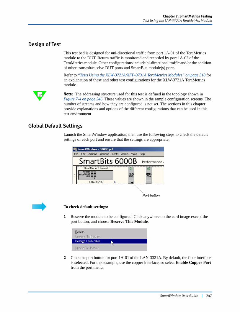
Chapter 7: SmartMetrics TestingTest Using the LAN-3321A TeraMetrics Module
Design of Test
This test bed is designed for uni-directional traffic from port 1A-01 of the TeraMetrics module to the DUT. Return traffic is monitored and recorded by port 1A-02 of the TeraMetrics module. Other configurations include bi-directional traffic and/or the addition of other transmit/receive DUT ports and SmartBits module(s) ports.
Refer to “Tests Using the XLW-3721A/XFP-3731A TeraMetrics Modules” on page 318 for an explanation of these and other test configurations for the XLW-3721A TeraMetrics module.
Note: The addressing structure used for this test is defined in the topology shown in Figure 7-4 on page 246. These values are shown in the sample configuration screens. The number of streams and how they are configured is not set. The sections in this chapter provide explanations and options of the different configurations that can be used in this test environment.
Global Default Settings
Launch the SmartWindow application, then use the following steps to check the default settings of each port and ensure that the settings are appropriate.
To check default settings:
1 Reserve the module to be configured. Click anywhere on the card image except the port button, and choose Reserve This Module.
2 Click the port button for port 1A-01 of the LAN-3321A. By default, the fiber interface is selected. For this example, use the copper interface, so select Enable Copper Port from the port menu.
Port button
SmartWindow User Guide | 247
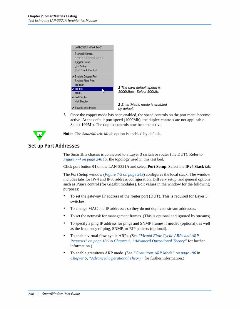
Chapter 7: SmartMetrics TestingTest Using the LAN-3321A TeraMetrics Module
3 Once the copper mode has been enabled, the speed controls on the port menu become active. At the default port speed (1000Mb), the duplex controls are not applicable. Select 100Mb. The duplex controls now become active.
Note: The SmartMetric Mode option is enabled by default.
Set up Port Addresses
The SmartBits chassis is connected to a Layer 3 switch or router (the DUT). Refer to Figure 7-4 on page 246 for the topology used in this test bed.
Click port button 01 on the LAN-3321A and select Port Setup. Select the IPv4 Stack tab.
The Port Setup window (Figure 7-5 on page 249) configures the local stack. The window includes tabs for IPv4 and IPv6 address configuration, DiffServ setup, and general options such as Pause control (for Gigabit modules). Edit values in the window for the following purposes:
• To set the gateway IP address of the router port (DUT). This is required for Layer 3 switches.
• To change MAC and IP addresses so they do not duplicate stream addresses.
• To set the netmask for management frames. (This is optional and ignored by streams).
• To specify a ping IP address for pings and SNMP frames if needed (optional), as well as the frequency of ping, SNMP, or RIP packets (optional).
• To enable virtual flow cyclic ARPs. (See “Virtual Flow Cyclic ARPs and ARP Requests” on page 186 in Chapter 5, “Advanced Operational Theory” for further information.)
• To enable gratuitous ARP mode. (See “Gratuitous ARP Mode” on page 196 in Chapter 5, “Advanced Operational Theory” for further information.)
1 The card default speed is
2 SmartMetric mode is enabled
1000Mbps. Select 100Mb.
by default.
248 | SmartWindow User Guide
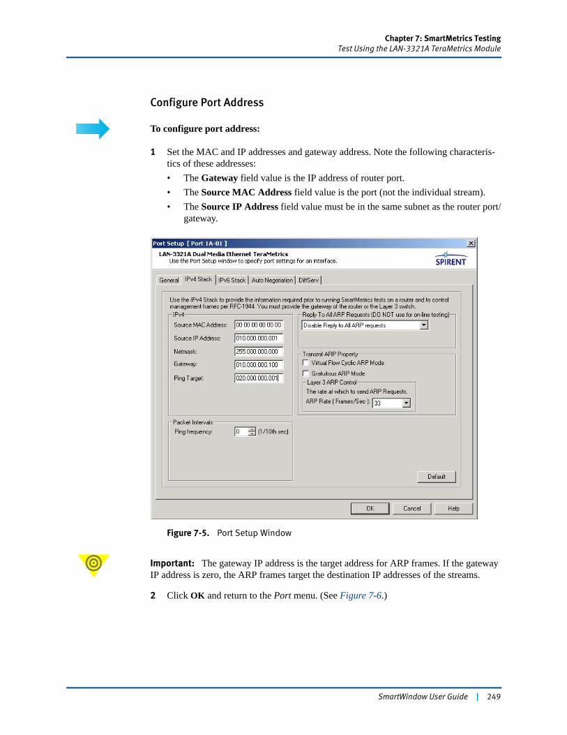
Chapter 7: SmartMetrics TestingTest Using the LAN-3321A TeraMetrics Module
Configure Port Address
To configure port address:
1 Set the MAC and IP addresses and gateway address. Note the following characteris-tics of these addresses:• The Gateway field value is the IP address of router port.• The Source MAC Address field value is the port (not the individual stream).• The Source IP Address field value must be in the same subnet as the router port/
gateway.
Figure 7-5. Port Setup Window
Important: The gateway IP address is the target address for ARP frames. If the gateway IP address is zero, the ARP frames target the destination IP addresses of the streams.
2 Click OK and return to the Port menu. (See Figure 7-6.)
SmartWindow User Guide | 249
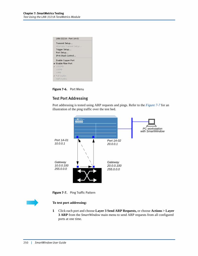
Chapter 7: SmartMetrics TestingTest Using the LAN-3321A TeraMetrics Module
Figure 7-6. Port Menu
Test Port Addressing
Port addressing is tested using ARP requests and pings. Refer to the Figure 7-7 for an illustration of the ping traffic over the test bed.
Figure 7-7. Ping Traffic Pattern
To test port addressing:
1 Click each port and choose Layer 3 Send ARP Requests, or choose Actions > Layer 3 ARP from the SmartWindow main menu to send ARP requests from all configured ports at one time.
GatewayGateway
Port 1A-0110.0.0.1
20.0.0.10010.0.0.100
Port 1A-0220.0.0.1
255.0.0.0 255.0.0.0
PC workstationwith SmartWindow
250 | SmartWindow User Guide
Chapter 7: SmartMetrics TestingTest Using the LAN-3321A TeraMetrics Module
2 Watch the SmartBits hardware or SmartWindow front panel LEDs. As each module transmits an ARP request, look for a brief green transmit and receive LED. If you do not see a momentary green receive LED light, the ARP response was not received.
For other streams and ARPs, try the ARP exchange times test to ensure that ARPs for all streams were received. (See “Viewing ARP Response Times” on page 314.)
Before transmitting traffic, it is helpful to ping the port IP addresses to confirm that the links to the DUT are working properly. Refer to “Send Traffic and View Counters” on page 265 on how to configure the DUT.
To ping the port IP addresses:
1 Click the port button for port 1A-01 and select Port Setup.2 Select the IPv4 Stack tab.3 Enter the IP address for port 1A-02 as the Ping Target field value.4 Set the Ping Frequency to 10.5 Click OK.
Once ping is initiated, the ARP resolution (for ping target) must be completed before the Ping is sent. Using Smart Counters or Capture validates this process.
After performing steps 4 and 5 above, the pinging starts. After pinging is performed, return to the port setup of each card, and turn off pinging by setting the Ping Frequency to 0 to keep other results more clearly segregated.
If the link is not active, check that the correct speed is selected. (Default speed for the LAN-3321A is 1,000 Mbps.) For this example, 100Mb was selected from the Port menu. (See “Global Default Settings” on page 247.)
Streams Setup Window
The Streams Setup window provides options for defining how the card schedules the streams that it transmits. Any option setup is performed before adding the streams, since these settings apply to the port overall. Return to the Port menu and select Transmit Setup. The Streams Setup menu appears. (See Figure 7-8 on page 252.)
SmartWindow User Guide | 251

Chapter 7: SmartMetrics TestingTest Using the LAN-3321A TeraMetrics Module
Figure 7-8. Sample Streams Setup Window
In the Global Settings pane, the Schedule Mode fields provide four options for scheduling:
• IFG — Interframe Gap: a fixed number of bit times between frames
• Random IFG — A varying number of bit times between frames
• Frame Rate — A defined frames-per-second rate of transmission for each stream
• Advanced Scheduler— The advanced scheduler does a better job of interleaving the streams when multiple streams are defined. The existing scheduler and advanced scheduler are both deterministic, meaning that each algorithm gives the same repeated results if the same configuration is used. The advanced scheduler increases the interleaving of the streams to avoid sending a large number of consecutive packets from a single stream. It signficantly reduces the jitter and out-of-place packets in the transmitted streams. It does so by spreading each stream through the sequence table according to its packet rate, rather than (as the current algorithm does) at the beginning or end of the sequence table.When this radio button is selected, the port schedules frames for transmission based on optimization that does not depend on Interframe Gaps (IFGs). Instead, the frames are ordered and transmitted according to a balanced mix that results in a smoother distribution of traffic between flows.
252 | SmartWindow User Guide
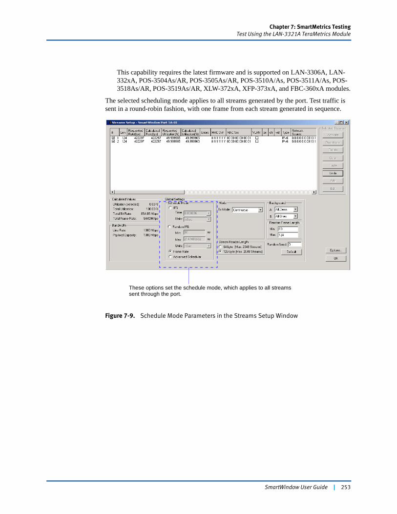
Chapter 7: SmartMetrics TestingTest Using the LAN-3321A TeraMetrics Module
This capability requires the latest firmware and is supported on LAN-3306A, LAN-332xA, POS-3504As/AR, POS-3505As/AR, POS-3510A/As, POS-3511A/As, POS-3518As/AR, POS-3519As/AR, XLW-372xA, XFP-373xA, and FBC-360xA modules.
The selected scheduling mode applies to all streams generated by the port. Test traffic is sent in a round-robin fashion, with one frame from each stream generated in sequence.
Figure 7-9. Schedule Mode Parameters in the Streams Setup Window
These options set the schedule mode, which applies to all streams sent through the port.
SmartWindow User Guide | 253
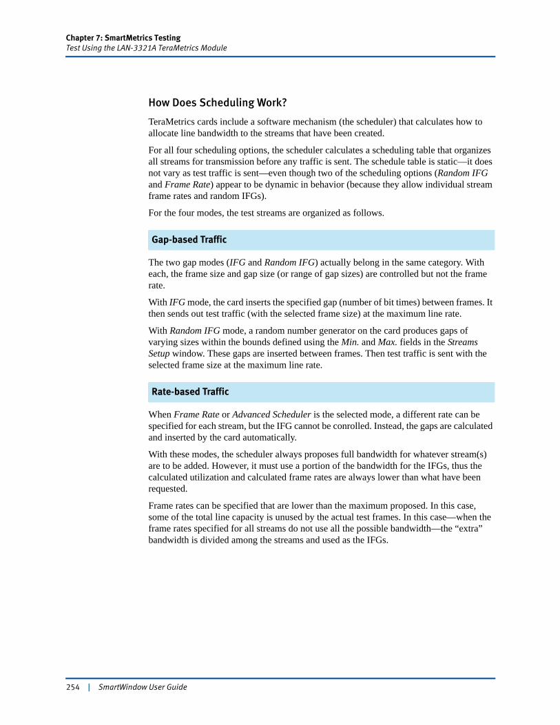
Chapter 7: SmartMetrics TestingTest Using the LAN-3321A TeraMetrics Module
How Does Scheduling Work?
TeraMetrics cards include a software mechanism (the scheduler) that calculates how to allocate line bandwidth to the streams that have been created.
For all four scheduling options, the scheduler calculates a scheduling table that organizes all streams for transmission before any traffic is sent. The schedule table is static—it does not vary as test traffic is sent—even though two of the scheduling options (Random IFG and Frame Rate) appear to be dynamic in behavior (because they allow individual stream frame rates and random IFGs).
For the four modes, the test streams are organized as follows.
Gap-based Traffic
The two gap modes (IFG and Random IFG) actually belong in the same category. With each, the frame size and gap size (or range of gap sizes) are controlled but not the frame rate.
With IFG mode, the card inserts the specified gap (number of bit times) between frames. It then sends out test traffic (with the selected frame size) at the maximum line rate.
With Random IFG mode, a random number generator on the card produces gaps of varying sizes within the bounds defined using the Min. and Max. fields in the Streams Setup window. These gaps are inserted between frames. Then test traffic is sent with the selected frame size at the maximum line rate.
Rate-based Traffic
When Frame Rate or Advanced Scheduler is the selected mode, a different rate can be specified for each stream, but the IFG cannot be conrolled. Instead, the gaps are calculated and inserted by the card automatically.
With these modes, the scheduler always proposes full bandwidth for whatever stream(s) are to be added. However, it must use a portion of the bandwidth for the IFGs, thus the calculated utilization and calculated frame rates are always lower than what have been requested.
Frame rates can be specified that are lower than the maximum proposed. In this case, some of the total line capacity is unused by the actual test frames. In this case—when the frame rates specified for all streams do not use all the possible bandwidth—the “extra” bandwidth is divided among the streams and used as the IFGs.
254 | SmartWindow User Guide
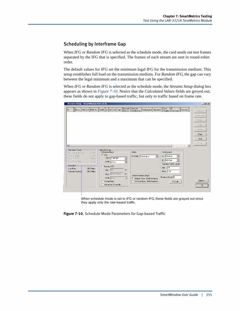
Chapter 7: SmartMetrics TestingTest Using the LAN-3321A TeraMetrics Module
Scheduling by Interframe Gap
When IFG or Random IFG is selected as the schedule mode, the card sends out test frames separated by the IFG that is specified. The frames of each stream are sent in round-robin order.
The default values for IFG set the minimum legal IFG for the transmission medium. This setup establishes full load on the transmission medium. For Random IFG, the gap can vary between the legal minimum and a maximum that can be specified.
When IFG or Random IFG is selected as the schedule mode, the Streams Setup dialog box appears as shown in Figure 7-10. Notice that the Calculated Values fields are greyed out; these fields do not apply to gap-based traffic, but only to traffic based on frame rate.
Figure 7-10. Schedule Mode Parameters for Gap-based Traffic
When schedule mode is set to IFG or random IFG, these fields are grayed out since they apply only the rate-based traffic.
SmartWindow User Guide | 255
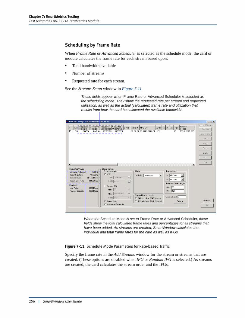
Chapter 7: SmartMetrics TestingTest Using the LAN-3321A TeraMetrics Module
Scheduling by Frame Rate
When Frame Rate or Advanced Scheduler is selected as the schedule mode, the card or module calculates the frame rate for each stream based upon:
• Total bandwidth available
• Number of streams
• Requested rate for each stream.
See the Streams Setup window in Figure 7-11.
Figure 7-11. Schedule Mode Parameters for Rate-based Traffic
Specify the frame rate in the Add Streams window for the stream or streams that are created. (These options are disabled when IFG or Random IFG is selected.) As streams are created, the card calculates the stream order and the IFGs.
When the Schedule Mode is set to Frame Rate or Advanced Scheduler, these fields show the total calculated frame rates and percentages for all streams that have been added. As streams are created, SmartWindow calculates the individual and total frame rates for the card as well as IFGs.
These fields appear when Frame Rate or Advanced Scheduler is selected as the scheduling mode. They show the requested rate per stream and requested utilization, as well as the actual (calculated) frame rate and utilization that results from how the card has allocated the available bandwidth.
256 | SmartWindow User Guide
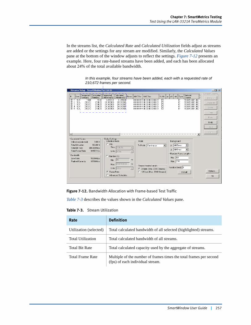
Chapter 7: SmartMetrics TestingTest Using the LAN-3321A TeraMetrics Module
In the streams list, the Calculated Rate and Calculated Utilization fields adjust as streams are added or the settings for any stream are modified. Similarly, the Calculated Values pane at the bottom of the window adjusts to reflect the settings. Figure 7-12 presents an example. Here, four rate-based streams have been added, and each has been allocated about 24% of the total available bandwidth.
Figure 7-12. Bandwidth Allocation with Frame-based Test Traffic
Table 7-3 describes the values shown in the Calculated Values pane.
Table 7-3. Stream Utilization
Rate Definition
Utilization (selected) Total calculated bandwidth of all selected (highlighted) streams.
Total Utilization Total calculated bandwidth of all streams.
Total Bit Rate Total calculated capacity used by the aggregate of streams.
Total Frame Rate Multiple of the number of frames times the total frames per second (fps) of each individual stream.
In this example, four streams have been added, each with a requested rate of 210,672 frames per second.
SmartWindow User Guide | 257
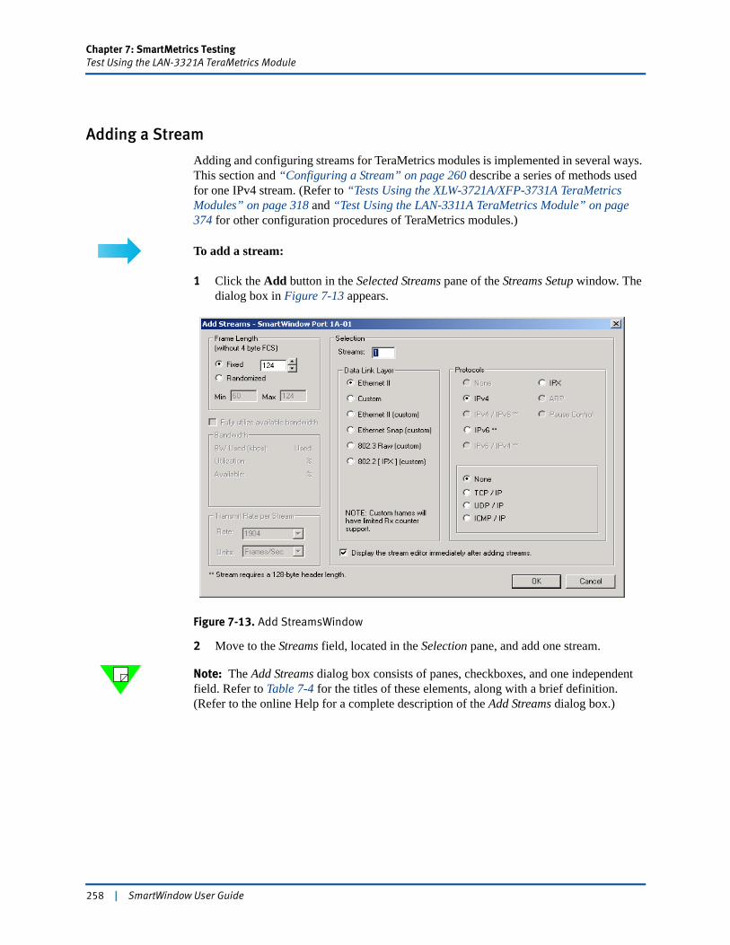
Chapter 7: SmartMetrics TestingTest Using the LAN-3321A TeraMetrics Module
Adding a Stream
Adding and configuring streams for TeraMetrics modules is implemented in several ways. This section and “Configuring a Stream” on page 260 describe a series of methods used for one IPv4 stream. (Refer to “Tests Using the XLW-3721A/XFP-3731A TeraMetrics Modules” on page 318 and “Test Using the LAN-3311A TeraMetrics Module” on page 374 for other configuration procedures of TeraMetrics modules.)
To add a stream:
1 Click the Add button in the Selected Streams pane of the Streams Setup window. The dialog box in Figure 7-13 appears.
Figure 7-13. Add StreamsWindow
2 Move to the Streams field, located in the Selection pane, and add one stream.
Note: The Add Streams dialog box consists of panes, checkboxes, and one independent field. Refer to Table 7-4 for the titles of these elements, along with a brief definition. (Refer to the online Help for a complete description of the Add Streams dialog box.)
258 | SmartWindow User Guide
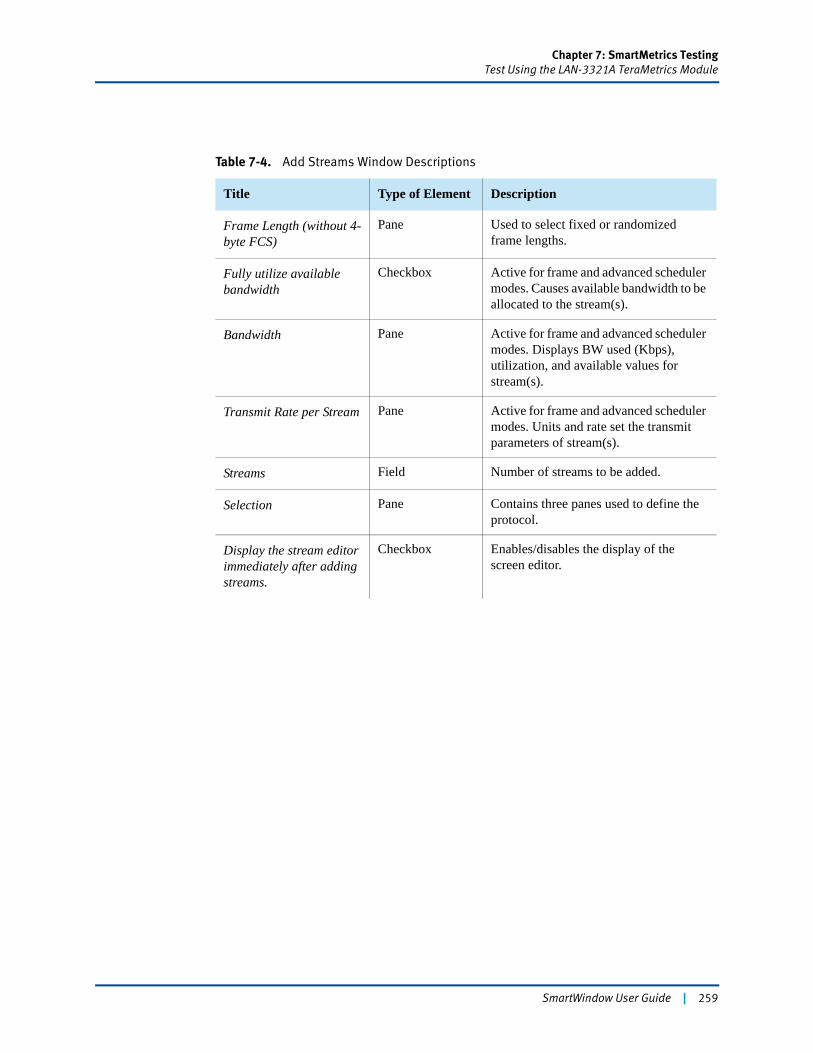
Chapter 7: SmartMetrics TestingTest Using the LAN-3321A TeraMetrics Module
Table 7-4. Add Streams Window Descriptions
Title Type of Element Description
Frame Length (without 4-byte FCS)
Pane Used to select fixed or randomized frame lengths.
Fully utilize available bandwidth
Checkbox Active for frame and advanced scheduler modes. Causes available bandwidth to be allocated to the stream(s).
Bandwidth Pane Active for frame and advanced scheduler modes. Displays BW used (Kbps), utilization, and available values for stream(s).
Transmit Rate per Stream Pane Active for frame and advanced scheduler modes. Units and rate set the transmit parameters of stream(s).
Streams Field Number of streams to be added.
Selection Pane Contains three panes used to define the protocol.
Display the stream editor immediately after adding streams.
Checkbox Enables/disables the display of the screen editor.
SmartWindow User Guide | 259
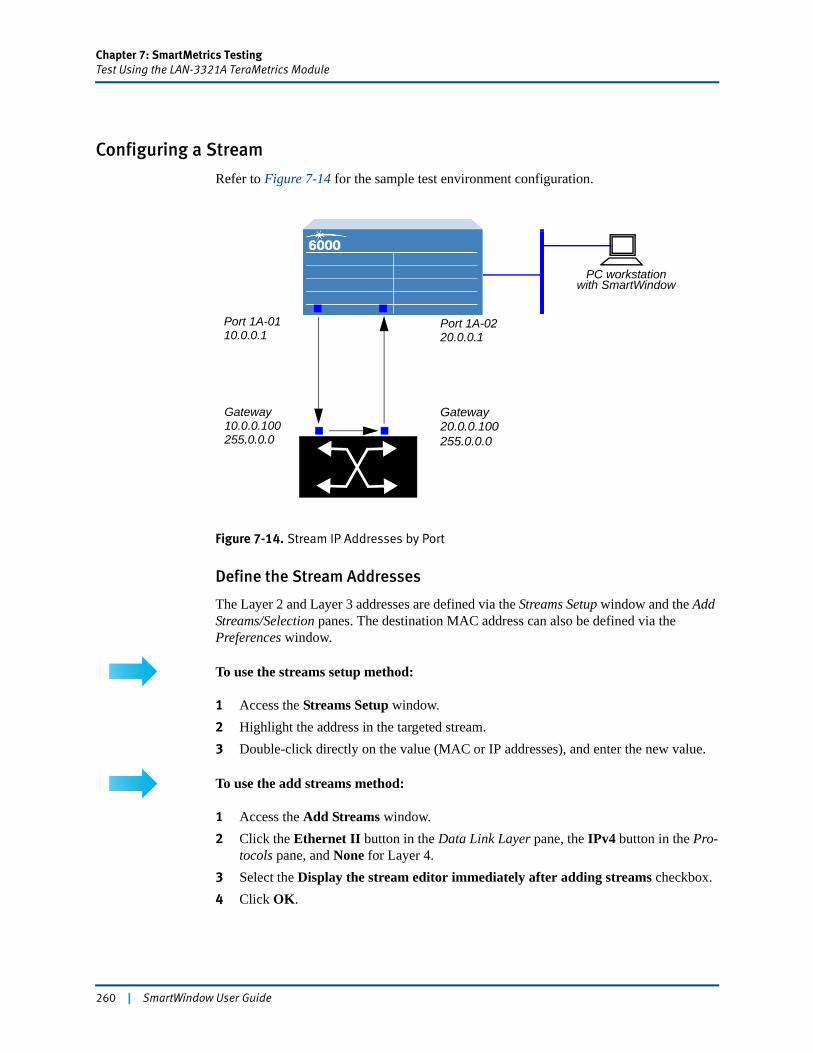
Chapter 7: SmartMetrics TestingTest Using the LAN-3321A TeraMetrics Module
Configuring a Stream
Refer to Figure 7-14 for the sample test environment configuration.
Figure 7-14. Stream IP Addresses by Port
Define the Stream Addresses
The Layer 2 and Layer 3 addresses are defined via the Streams Setup window and the Add Streams/Selection panes. The destination MAC address can also be defined via the Preferences window.
To use the streams setup method:
1 Access the Streams Setup window.2 Highlight the address in the targeted stream.3 Double-click directly on the value (MAC or IP addresses), and enter the new value.
To use the add streams method:
1 Access the Add Streams window.2 Click the Ethernet II button in the Data Link Layer pane, the IPv4 button in the Pro-
tocols pane, and None for Layer 4.3 Select the Display the stream editor immediately after adding streams checkbox.4 Click OK.
GatewayGateway
Port 1A-0110.0.0.1
20.0.0.10010.0.0.100
Port 1A-0220.0.0.1
255.0.0.0 255.0.0.0
PC workstationwith SmartWindow
260 | SmartWindow User Guide
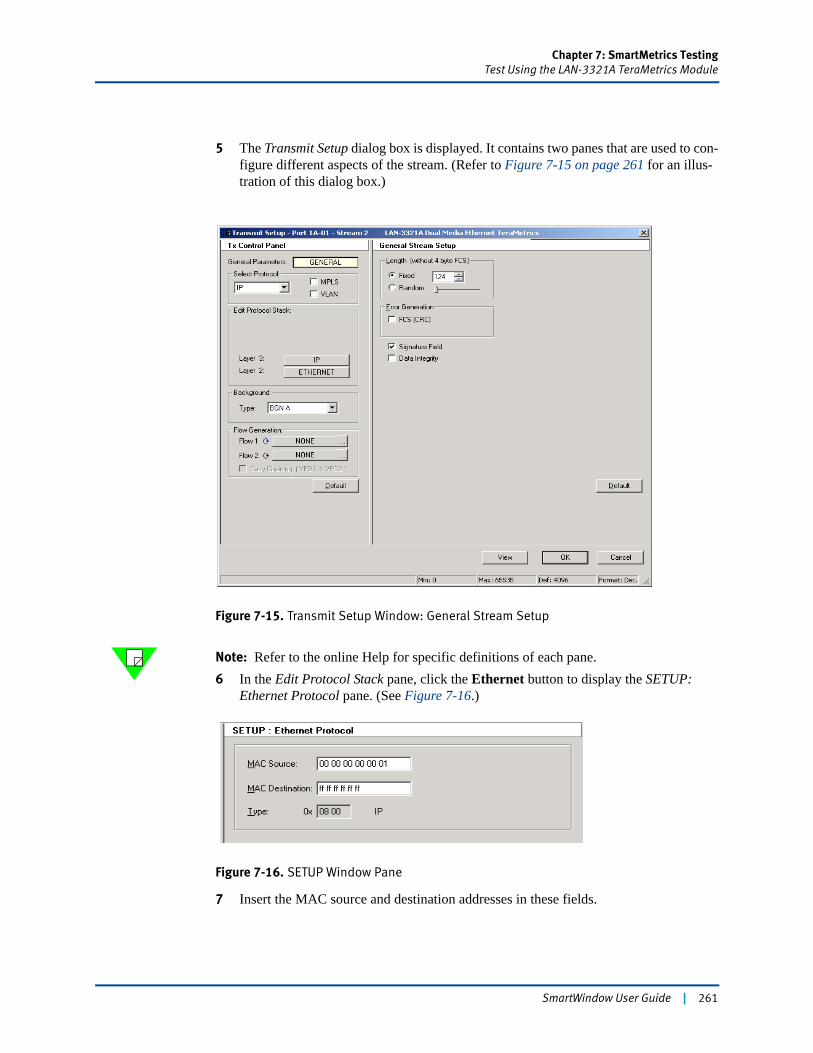
Chapter 7: SmartMetrics TestingTest Using the LAN-3321A TeraMetrics Module
5 The Transmit Setup dialog box is displayed. It contains two panes that are used to con-figure different aspects of the stream. (Refer to Figure 7-15 on page 261 for an illus-tration of this dialog box.)
Figure 7-15. Transmit Setup Window: General Stream Setup
Note: Refer to the online Help for specific definitions of each pane.6 In the Edit Protocol Stack pane, click the Ethernet button to display the SETUP:
Ethernet Protocol pane. (See Figure 7-16.)
Figure 7-16. SETUP Window Pane
7 Insert the MAC source and destination addresses in these fields.
SmartWindow User Guide | 261
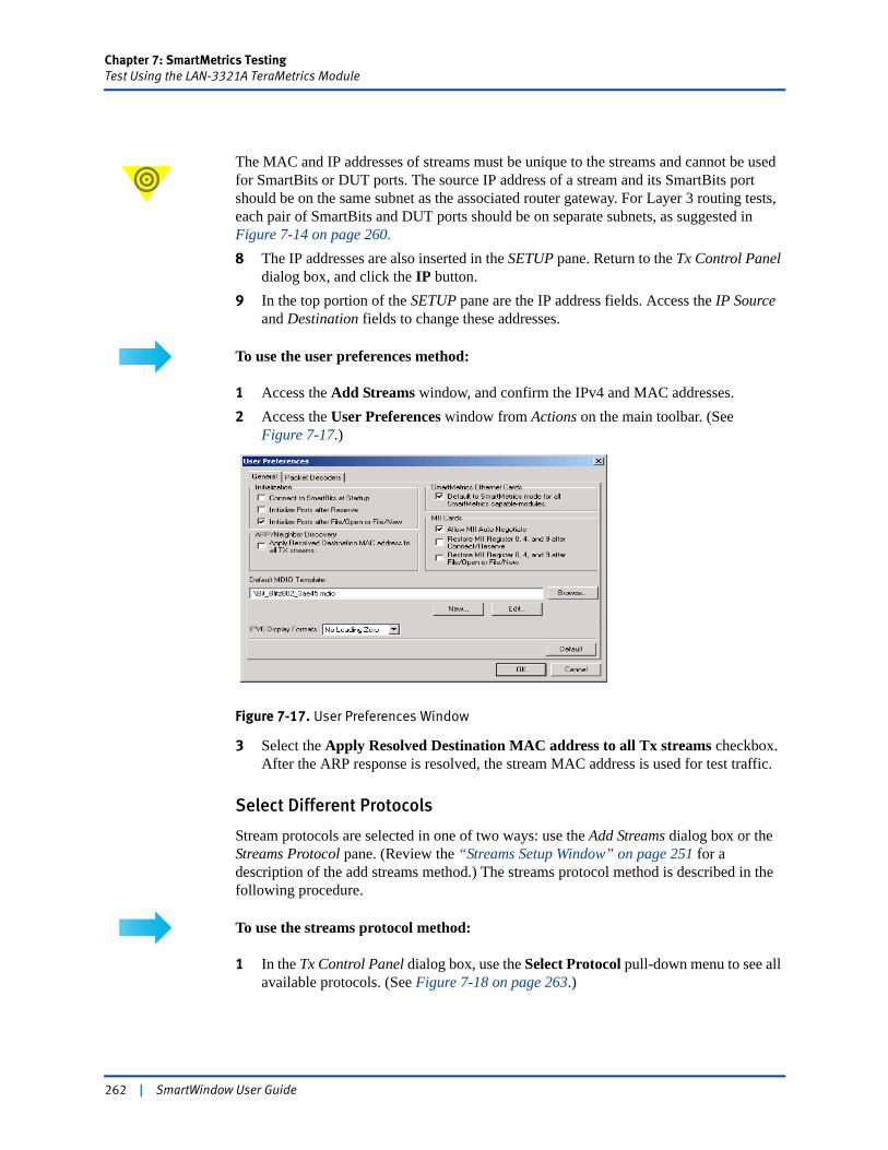
Chapter 7: SmartMetrics TestingTest Using the LAN-3321A TeraMetrics Module
The MAC and IP addresses of streams must be unique to the streams and cannot be used for SmartBits or DUT ports. The source IP address of a stream and its SmartBits port should be on the same subnet as the associated router gateway. For Layer 3 routing tests, each pair of SmartBits and DUT ports should be on separate subnets, as suggested in Figure 7-14 on page 260.8 The IP addresses are also inserted in the SETUP pane. Return to the Tx Control Panel
dialog box, and click the IP button.9 In the top portion of the SETUP pane are the IP address fields. Access the IP Source
and Destination fields to change these addresses.
To use the user preferences method:
1 Access the Add Streams window, and confirm the IPv4 and MAC addresses.2 Access the User Preferences window from Actions on the main toolbar. (See
Figure 7-17.)
Figure 7-17. User Preferences Window
3 Select the Apply Resolved Destination MAC address to all Tx streams checkbox. After the ARP response is resolved, the stream MAC address is used for test traffic.
Select Different Protocols
Stream protocols are selected in one of two ways: use the Add Streams dialog box or the Streams Protocol pane. (Review the “Streams Setup Window” on page 251 for a description of the add streams method.) The streams protocol method is described in the following procedure.
To use the streams protocol method:
1 In the Tx Control Panel dialog box, use the Select Protocol pull-down menu to see all available protocols. (See Figure 7-18 on page 263.)
262 | SmartWindow User Guide
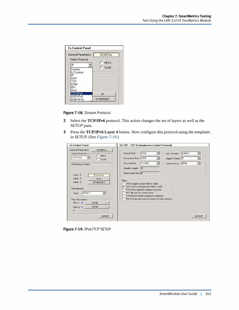
Chapter 7: SmartMetrics TestingTest Using the LAN-3321A TeraMetrics Module
Figure 7-18. Stream Protocol
2 Select the TCP/IPv6 protocol. This action changes the set of layers as well as the SETUP pane.
3 Press the TCP/IPv6 Layer 4 button. Now configure this protocol using the templates in SETUP. (See Figure 7-19.)
Figure 7-19. IPv6/TCP SETUP
SmartWindow User Guide | 263
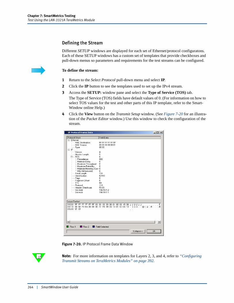
Chapter 7: SmartMetrics TestingTest Using the LAN-3321A TeraMetrics Module
Defining the Stream
Different SETUP windows are displayed for each set of Ethernet/protocol configuratons. Each of these SETUP windows has a custom set of templates that provide checkboxes and pull-down menus so parameters and requirements for the test streams can be configured.
To define the stream:
1 Return to the Select Protocol pull-down menu and select IP.2 Click the IP button to see the templates used to set up the IPv4 stream.3 Access the SETUP: window pane and select the Type of Service (TOS) tab.
The Type of Service (TOS) fields have default values of 0. (For information on how to select TOS values for the test and other parts of this IP template, refer to the Smart-Window online Help.)
4 Click the View button on the Transmit Setup window. (See Figure 7-20 for an illustra-tion of the Packet Editor window.) Use this window to check the configuration of the stream.
Figure 7-20. IP Protocol Frame Data Window
Note: For more information on templates for Layers 2, 3, and 4, refer to “Configuring Transmit Streams on TeraMetrics Modules” on page 392.
264 | SmartWindow User Guide
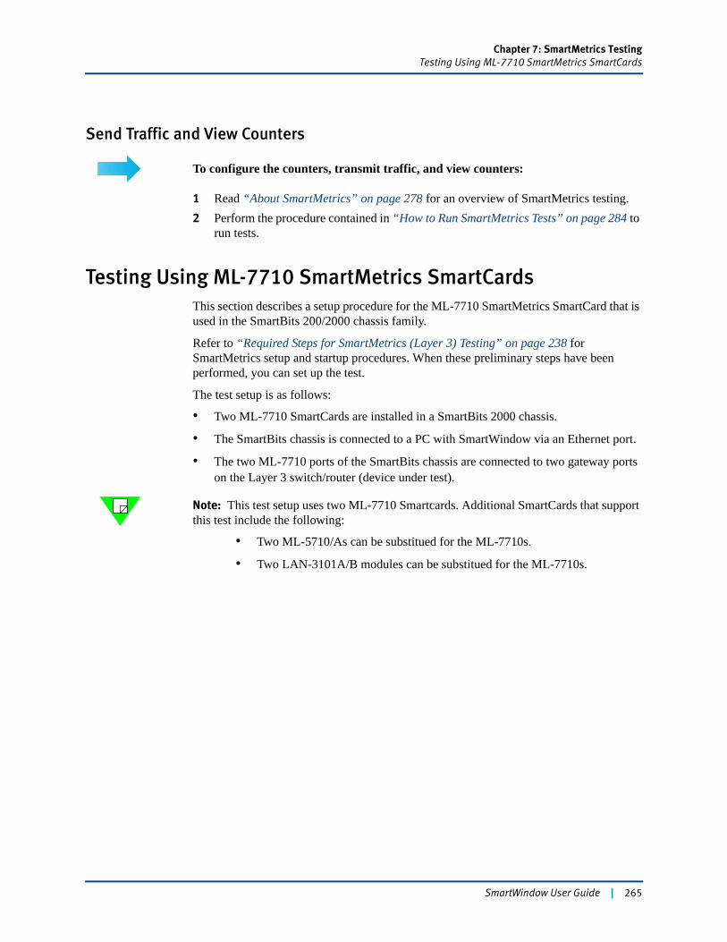
Chapter 7: SmartMetrics TestingTesting Using ML-7710 SmartMetrics SmartCards
Send Traffic and View Counters
To configure the counters, transmit traffic, and view counters:
1 Read “About SmartMetrics” on page 278 for an overview of SmartMetrics testing.2 Perform the procedure contained in “How to Run SmartMetrics Tests” on page 284 to
run tests.
Testing Using ML-7710 SmartMetrics SmartCardsThis section describes a setup procedure for the ML-7710 SmartMetrics SmartCard that is used in the SmartBits 200/2000 chassis family.
Refer to “Required Steps for SmartMetrics (Layer 3) Testing” on page 238 for SmartMetrics setup and startup procedures. When these preliminary steps have been performed, you can set up the test.
The test setup is as follows:
• Two ML-7710 SmartCards are installed in a SmartBits 2000 chassis.
• The SmartBits chassis is connected to a PC with SmartWindow via an Ethernet port.
• The two ML-7710 ports of the SmartBits chassis are connected to two gateway ports on the Layer 3 switch/router (device under test).
Note: This test setup uses two ML-7710 Smartcards. Additional SmartCards that support this test include the following:
• Two ML-5710/As can be substitued for the ML-7710s.
• Two LAN-3101A/B modules can be substitued for the ML-7710s.
SmartWindow User Guide | 265
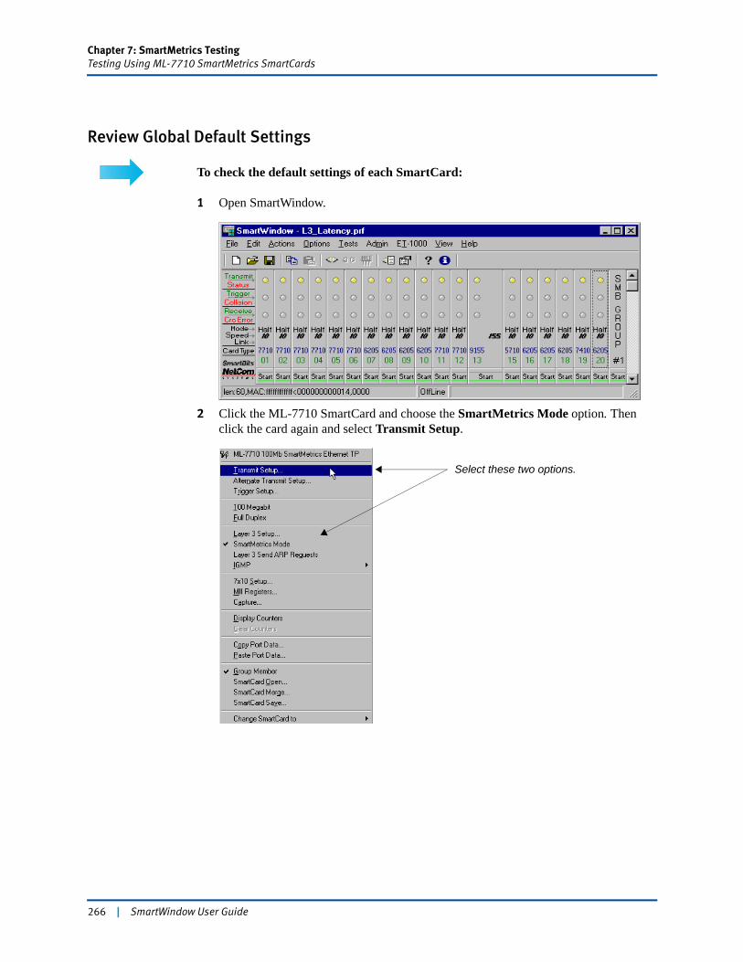
Chapter 7: SmartMetrics TestingTesting Using ML-7710 SmartMetrics SmartCards
Review Global Default Settings
To check the default settings of each SmartCard:
1 Open SmartWindow.
2 Click the ML-7710 SmartCard and choose the SmartMetrics Mode option. Then click the card again and select Transmit Setup.
Select these two options.
266 | SmartWindow User Guide
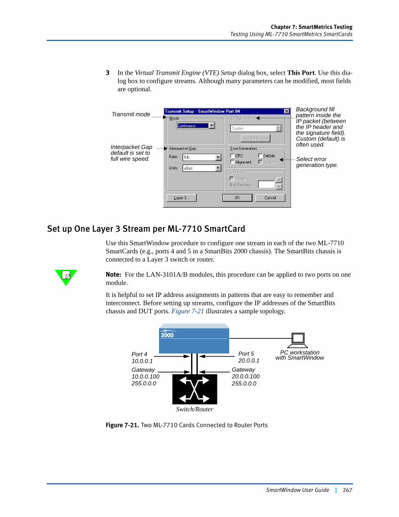
Chapter 7: SmartMetrics TestingTesting Using ML-7710 SmartMetrics SmartCards
3 In the Virtual Transmit Engine (VTE) Setup dialog box, select This Port. Use this dia-log box to configure streams. Although many parameters can be modified, most fields are optional.
Set up One Layer 3 Stream per ML-7710 SmartCard
Use this SmartWindow procedure to configure one stream in each of the two ML-7710 SmartCards (e.g., ports 4 and 5 in a SmartBits 2000 chassis). The SmartBits chassis is connected to a Layer 3 switch or router.
Note: For the LAN-3101A/B modules, this procedure can be applied to two ports on one module.
It is helpful to set IP address assignments in patterns that are easy to remember and interconnect. Before setting up streams, configure the IP addresses of the SmartBits chassis and DUT ports. Figure 7-21 illustrates a sample topology.
Figure 7-21. Two ML-7710 Cards Connected to Router Ports
Background fill pattern inside the IP packet (between the IP header and the signature field). Custom (default) is often used.
Transmit mode
Interpacket Gapdefault is set tofull wire speed. Select error
generation type.
PC workstationwith SmartWindow
Switch/Router
GatewayGateway
Port 410.0.0.1
20.0.0.10010.0.0.100
Port 520.0.0.1
255.0.0.0 255.0.0.0
SmartWindow User Guide | 267
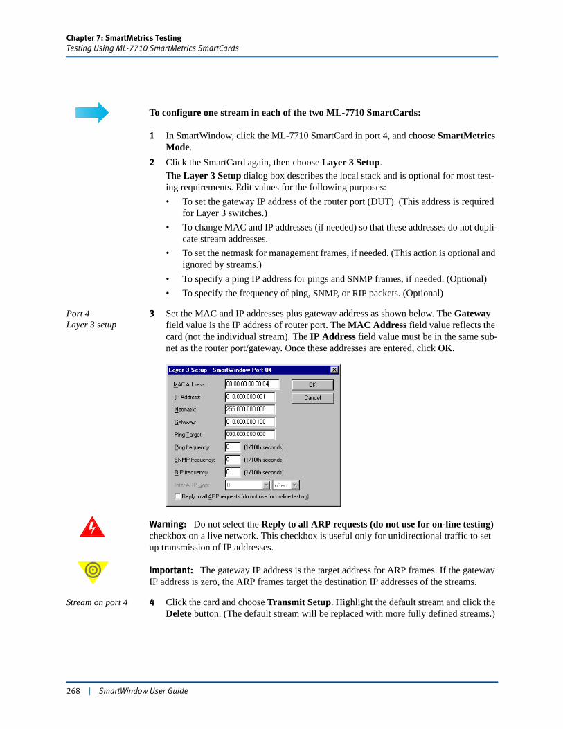
Chapter 7: SmartMetrics TestingTesting Using ML-7710 SmartMetrics SmartCards
To configure one stream in each of the two ML-7710 SmartCards:
1 In SmartWindow, click the ML-7710 SmartCard in port 4, and choose SmartMetrics Mode.
2 Click the SmartCard again, then choose Layer 3 Setup.The Layer 3 Setup dialog box describes the local stack and is optional for most test-ing requirements. Edit values for the following purposes:• To set the gateway IP address of the router port (DUT). (This address is required
for Layer 3 switches.)• To change MAC and IP addresses (if needed) so that these addresses do not dupli-
cate stream addresses.• To set the netmask for management frames, if needed. (This action is optional and
ignored by streams.)• To specify a ping IP address for pings and SNMP frames, if needed. (Optional)• To specify the frequency of ping, SNMP, or RIP packets. (Optional)
Port 4Layer 3 setup
3 Set the MAC and IP addresses plus gateway address as shown below. The Gateway field value is the IP address of router port. The MAC Address field value reflects the card (not the individual stream). The IP Address field value must be in the same sub-net as the router port/gateway. Once these addresses are entered, click OK.
Warning: Do not select the Reply to all ARP requests (do not use for on-line testing) checkbox on a live network. This checkbox is useful only for unidirectional traffic to set up transmission of IP addresses.
Important: The gateway IP address is the target address for ARP frames. If the gateway IP address is zero, the ARP frames target the destination IP addresses of the streams.
Stream on port 4 4 Click the card and choose Transmit Setup. Highlight the default stream and click the Delete button. (The default stream will be replaced with more fully defined streams.)
268 | SmartWindow User Guide
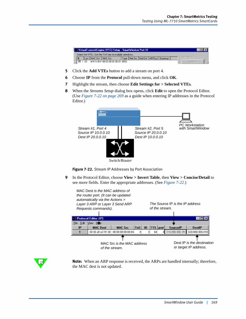
Chapter 7: SmartMetrics TestingTesting Using ML-7710 SmartMetrics SmartCards
5 Click the Add VTEs button to add a stream on port 4.6 Choose IP from the Protocol pull-down menu, and click OK.7 Highlight the stream, then choose Edit Settings for > Selected VTEs.8 When the Streams Setup dialog box opens, click Edit to open the Protocol Editor.
(Use Figure 7-22 on page 269 as a guide when entering IP addresses in the Protocol Editor.)
Figure 7-22. Stream IP Addresses by Port Association
9 In the Protocol Editor, choose View > Invert Table, then View > Concise/Detail to see more fields. Enter the appropriate addresses. (See Figure 7-22.)
Note: When an ARP response is received, the ARPs are handled internally; therefore, the MAC dest is not updated.
PC Workstationwith SmartWindow
Switch/Router
Stream #1, Port 4
Dest IP 20.0.0.10Source IP 10.0.0.10
Stream #2, Port 5
Dest IP 10.0.0.10Source IP 20.0.0.10
MAC Dest is the MAC address of the router port. (It can be updated automatically via the Actions > Layer 3 ARP or Layer 3 Send ARP Requests commands).
MAC Src is the MAC address of the stream.
The Source IP is the IP address of the stream.
Dest IP is the destination or target IP address.
SmartWindow User Guide | 269
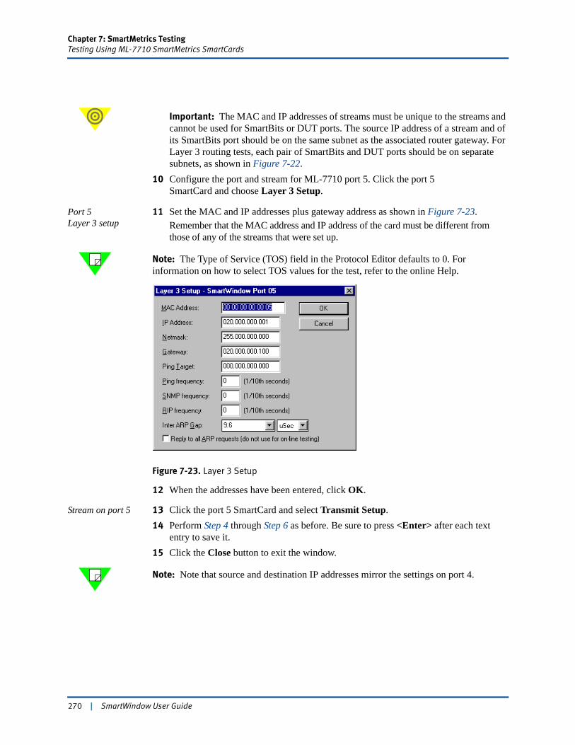
Chapter 7: SmartMetrics TestingTesting Using ML-7710 SmartMetrics SmartCards
Important: The MAC and IP addresses of streams must be unique to the streams and cannot be used for SmartBits or DUT ports. The source IP address of a stream and of its SmartBits port should be on the same subnet as the associated router gateway. For Layer 3 routing tests, each pair of SmartBits and DUT ports should be on separate subnets, as shown in Figure 7-22.
10 Configure the port and stream for ML-7710 port 5. Click the port 5SmartCard and choose Layer 3 Setup.
Port 5Layer 3 setup
11 Set the MAC and IP addresses plus gateway address as shown in Figure 7-23.Remember that the MAC address and IP address of the card must be different from those of any of the streams that were set up.
Note: The Type of Service (TOS) field in the Protocol Editor defaults to 0. For information on how to select TOS values for the test, refer to the online Help.
Figure 7-23. Layer 3 Setup
12 When the addresses have been entered, click OK.
Stream on port 5 13 Click the port 5 SmartCard and select Transmit Setup. 14 Perform Step 4 through Step 6 as before. Be sure to press <Enter> after each text
entry to save it. 15 Click the Close button to exit the window.
Note: Note that source and destination IP addresses mirror the settings on port 4.
270 | SmartWindow User Guide
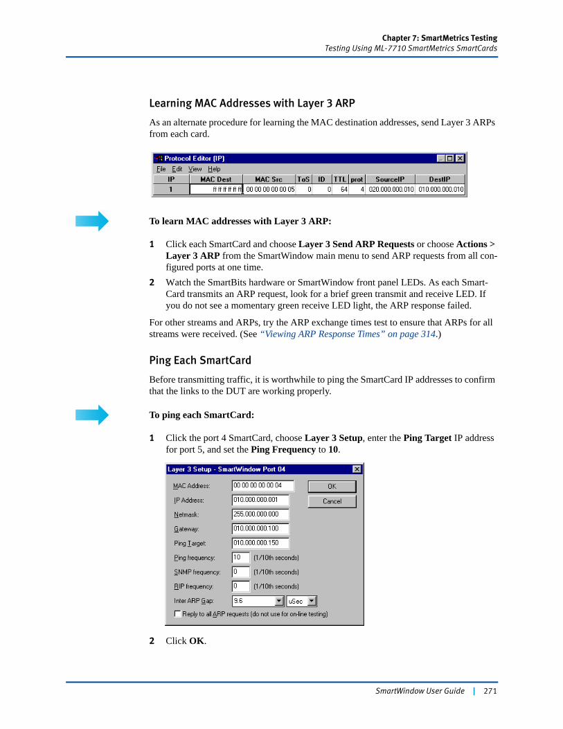
Chapter 7: SmartMetrics TestingTesting Using ML-7710 SmartMetrics SmartCards
Learning MAC Addresses with Layer 3 ARP
As an alternate procedure for learning the MAC destination addresses, send Layer 3 ARPs from each card.
To learn MAC addresses with Layer 3 ARP:
1 Click each SmartCard and choose Layer 3 Send ARP Requests or choose Actions > Layer 3 ARP from the SmartWindow main menu to send ARP requests from all con-figured ports at one time.
2 Watch the SmartBits hardware or SmartWindow front panel LEDs. As each Smart-Card transmits an ARP request, look for a brief green transmit and receive LED. If you do not see a momentary green receive LED light, the ARP response failed.
For other streams and ARPs, try the ARP exchange times test to ensure that ARPs for all streams were received. (See “Viewing ARP Response Times” on page 314.)
Ping Each SmartCard
Before transmitting traffic, it is worthwhile to ping the SmartCard IP addresses to confirm that the links to the DUT are working properly.
To ping each SmartCard:
1 Click the port 4 SmartCard, choose Layer 3 Setup, enter the Ping Target IP address for port 5, and set the Ping Frequency to 10.
2 Click OK.
SmartWindow User Guide | 271
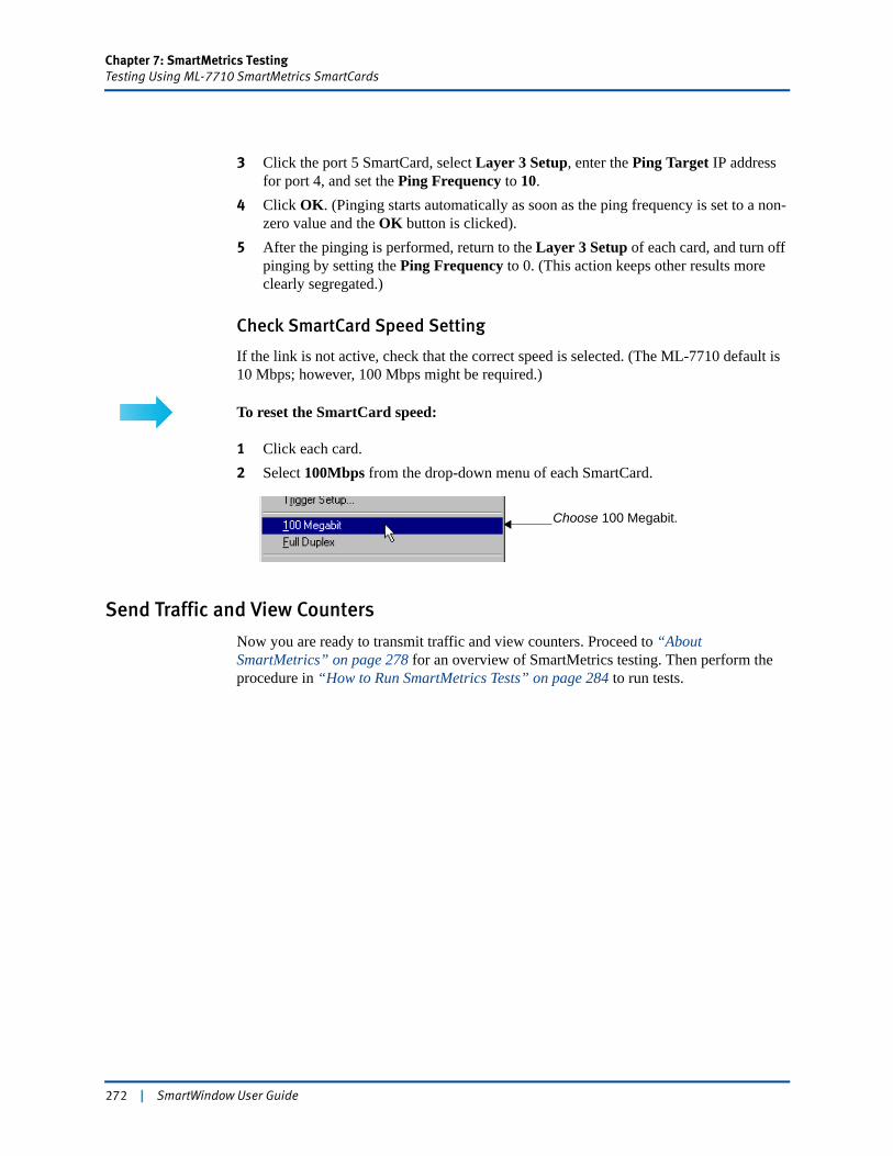
Chapter 7: SmartMetrics TestingTesting Using ML-7710 SmartMetrics SmartCards
3 Click the port 5 SmartCard, select Layer 3 Setup, enter the Ping Target IP address for port 4, and set the Ping Frequency to 10.
4 Click OK. (Pinging starts automatically as soon as the ping frequency is set to a non-zero value and the OK button is clicked).
5 After the pinging is performed, return to the Layer 3 Setup of each card, and turn off pinging by setting the Ping Frequency to 0. (This action keeps other results more clearly segregated.)
Check SmartCard Speed Setting
If the link is not active, check that the correct speed is selected. (The ML-7710 default is 10 Mbps; however, 100 Mbps might be required.)
To reset the SmartCard speed:
1 Click each card.2 Select 100Mbps from the drop-down menu of each SmartCard.
Send Traffic and View Counters
Now you are ready to transmit traffic and view counters. Proceed to “About SmartMetrics” on page 278 for an overview of SmartMetrics testing. Then perform the procedure in “How to Run SmartMetrics Tests” on page 284 to run tests.
Choose 100 Megabit.
272 | SmartWindow User Guide
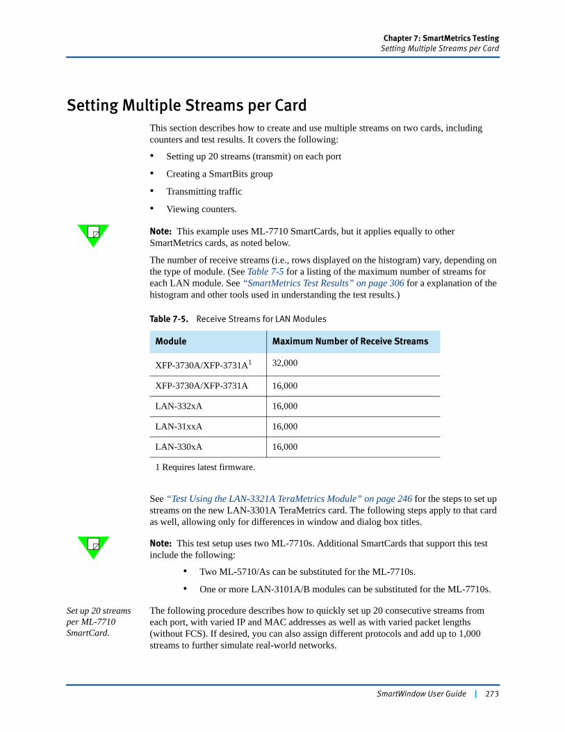
Chapter 7: SmartMetrics TestingSetting Multiple Streams per Card
Setting Multiple Streams per CardThis section describes how to create and use multiple streams on two cards, including counters and test results. It covers the following:
• Setting up 20 streams (transmit) on each port
• Creating a SmartBits group
• Transmitting traffic
• Viewing counters.
Note: This example uses ML-7710 SmartCards, but it applies equally to other SmartMetrics cards, as noted below.
The number of receive streams (i.e., rows displayed on the histogram) vary, depending on the type of module. (See Table 7-5 for a listing of the maximum number of streams for each LAN module. See “SmartMetrics Test Results” on page 306 for a explanation of the histogram and other tools used in understanding the test results.)
See “Test Using the LAN-3321A TeraMetrics Module” on page 246 for the steps to set up streams on the new LAN-3301A TeraMetrics card. The following steps apply to that card as well, allowing only for differences in window and dialog box titles.
Note: This test setup uses two ML-7710s. Additional SmartCards that support this test include the following:
• Two ML-5710/As can be substituted for the ML-7710s.
• One or more LAN-3101A/B modules can be substituted for the ML-7710s.
Set up 20 streams per ML-7710 SmartCard.
The following procedure describes how to quickly set up 20 consecutive streams from each port, with varied IP and MAC addresses as well as with varied packet lengths (without FCS). If desired, you can also assign different protocols and add up to 1,000 streams to further simulate real-world networks.
Table 7-5. Receive Streams for LAN Modules
Module Maximum Number of Receive Streams
XFP-3730A/XFP-3731A1 32,000
XFP-3730A/XFP-3731A 16,000
LAN-332xA 16,000
LAN-31xxA 16,000
LAN-330xA 16,000
1 Requires latest firmware.
SmartWindow User Guide | 273

Chapter 7: SmartMetrics TestingSetting Multiple Streams per Card
To set up multiple streams:
1 Click the first card or port and choose Transmit Setup.2 Highlight the default stream and click the Delete button. It is helpful to delete the
default stream and then configure all new streams.
Note: TeraMetrics modules (such as the LAN-3301A) have no default streams.3 Click Add VTEs and enter 20 VTEs.
4 Click the Randomized button in the Frame Length pane (without FCS).
Note: It is recommended that you begin with fixed frame lengths to set initial testing benchmarks, then try randomized frame lengths for contrast. However, for this test, use the Randomized option.
5 Select IP in the Protocol drop-down menu.6 Click OK. The Protocol Editor appears with default addresses for 20 streams.7 Edit the first stream as follows:
Source IP address:10.0.0.4Destination IP address (the Port 5 VTE stream):20.0.0.5
8 Highlight the entire SourceIP column, then right-click the top entry and select Copy Down. Right-click again and select Fill Increment 0.0.0.x.
9 Repeat Step 8 for the DestIP column.
Two ML-7710 cards configured with 20
sending and receiving traffic through a DUT. streams each can simulate 40 PC hosts
274 | SmartWindow User Guide
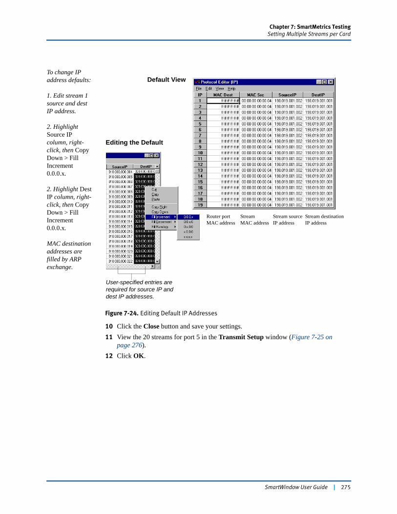
Chapter 7: SmartMetrics TestingSetting Multiple Streams per Card
To change IP address defaults:
1. Edit stream 1 source and dest IP address.
2. Highlight Source IP column, right-click, then Copy Down > Fill Increment 0.0.0.x.
2. Highlight Dest IP column, right-click, then Copy Down > Fill Increment 0.0.0.x.
MAC destination addresses are filled by ARP exchange.
Figure 7-24. Editing Default IP Addresses
10 Click the Close button and save your settings.11 View the 20 streams for port 5 in the Transmit Setup window (Figure 7-25 on
page 276).12 Click OK.
Default View
Editing the Default
User-specified entries are required for source IP and dest IP addresses.
Router portMAC address
StreamMAC address
Stream sourceIP address
Stream destinationIP address
SmartWindow User Guide | 275
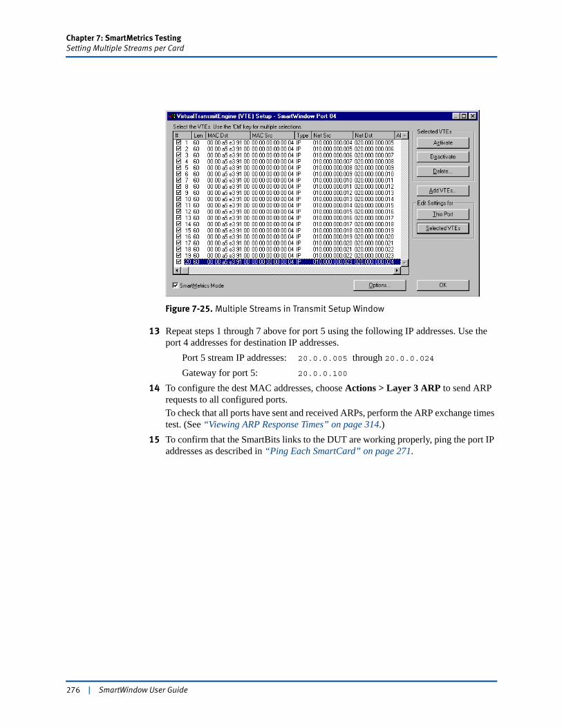
Chapter 7: SmartMetrics TestingSetting Multiple Streams per Card
Figure 7-25. Multiple Streams in Transmit Setup Window
13 Repeat steps 1 through 7 above for port 5 using the following IP addresses. Use the port 4 addresses for destination IP addresses.
Port 5 stream IP addresses: 20.0.0.005 through 20.0.0.024Gateway for port 5: 20.0.0.100
14 To configure the dest MAC addresses, choose Actions > Layer 3 ARP to send ARP requests to all configured ports.To check that all ports have sent and received ARPs, perform the ARP exchange times test. (See “Viewing ARP Response Times” on page 314.)
15 To confirm that the SmartBits links to the DUT are working properly, ping the port IP addresses as described in “Ping Each SmartCard” on page 271.
276 | SmartWindow User Guide
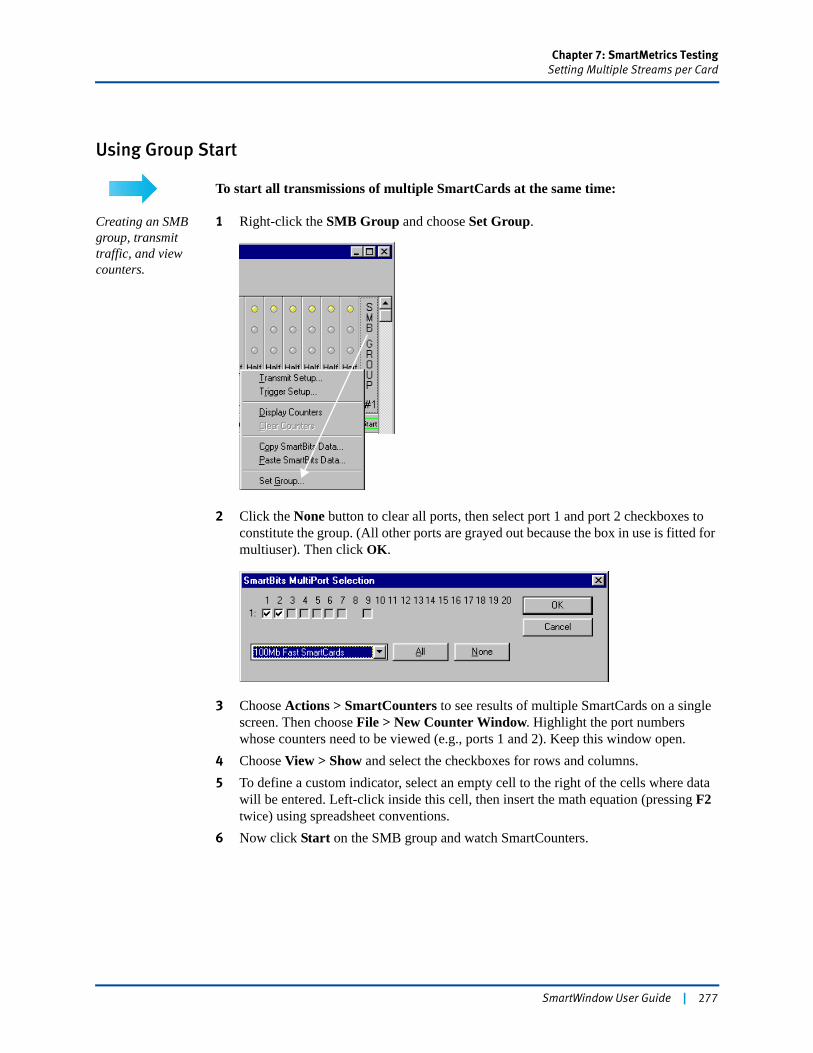
Chapter 7: SmartMetrics TestingSetting Multiple Streams per Card
Using Group Start
To start all transmissions of multiple SmartCards at the same time:
Creating an SMB group, transmit traffic, and view counters.
1 Right-click the SMB Group and choose Set Group.
2 Click the None button to clear all ports, then select port 1 and port 2 checkboxes to constitute the group. (All other ports are grayed out because the box in use is fitted for multiuser). Then click OK.
3 Choose Actions > SmartCounters to see results of multiple SmartCards on a single screen. Then choose File > New Counter Window. Highlight the port numbers whose counters need to be viewed (e.g., ports 1 and 2). Keep this window open.
4 Choose View > Show and select the checkboxes for rows and columns.5 To define a custom indicator, select an empty cell to the right of the cells where data
will be entered. Left-click inside this cell, then insert the math equation (pressing F2 twice) using spreadsheet conventions.
6 Now click Start on the SMB group and watch SmartCounters.
SmartWindow User Guide | 277
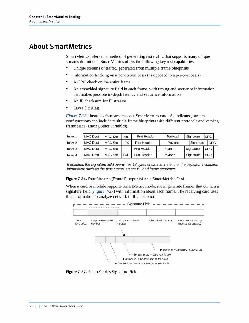
Chapter 7: SmartMetrics TestingAbout SmartMetrics
About SmartMetricsSmartMetrics refers to a method of generating test traffic that supports many unique streams definitions. SmartMetrics offers the following key test capabilities:• Unique streams of traffic, generated from multiple frame blueprints• Information tracking on a per-stream basis (as opposed to a per-port basis)• A CRC check on the entire frame• An embedded signature field in each frame, with timing and sequence information,
that makes possible in-depth latency and sequence information• An IP checksum for IP streams.• Layer 3 testing.
Figure 7-26 illustrates four streams on a SmartMetrics card. As indicated, stream configurations can include multiple frame blueprints with different protocols and varying frame sizes (among other variables).
Figure 7-26. Four Streams (Frame Blueprints) on a SmartMetrics Card
When a card or module supports SmartMetric mode, it can generate frames that contain a signature field (Figure 7-27) with information about each frame. The receiving card uses this information to analyze network traffic behavior.
Figure 7-27. SmartMetrics Signature Field
CRC
CRC
CRC
CRC
Signature
Signature
Signature
SignaturePayload
Payload
Payload
Payload
Prot Header
Prot Header
Prot Header
Prot HeaderTCP
IP
IPX
UDPMAC SrcMAC Dest
MAC Src
MAC Src
MAC Src
MAC Dest
MAC Dest
MAC Dest
Index 1
Index 2
Index 3
Index 4
If enabled, the signature field overwrites 18 bytes of data at the end of the payload. It contains information such as the time stamp, steam ID, and frame sequence.
4-byte stream/VTEnumber
4-byte sequencecount
4-byte Tx timestamp 4-byte check pattern(inverse timestamp)
2-bytetime offset
Bits 0-15 = Stream/VTE ID# (1-n)
Bits 16-23 = Card ID# (0-79)Bits 24-27 = Chassis ID# (0 for now)
Bits 28-31 = Check Number (example IP=2)
Signature Field
278 | SmartWindow User Guide
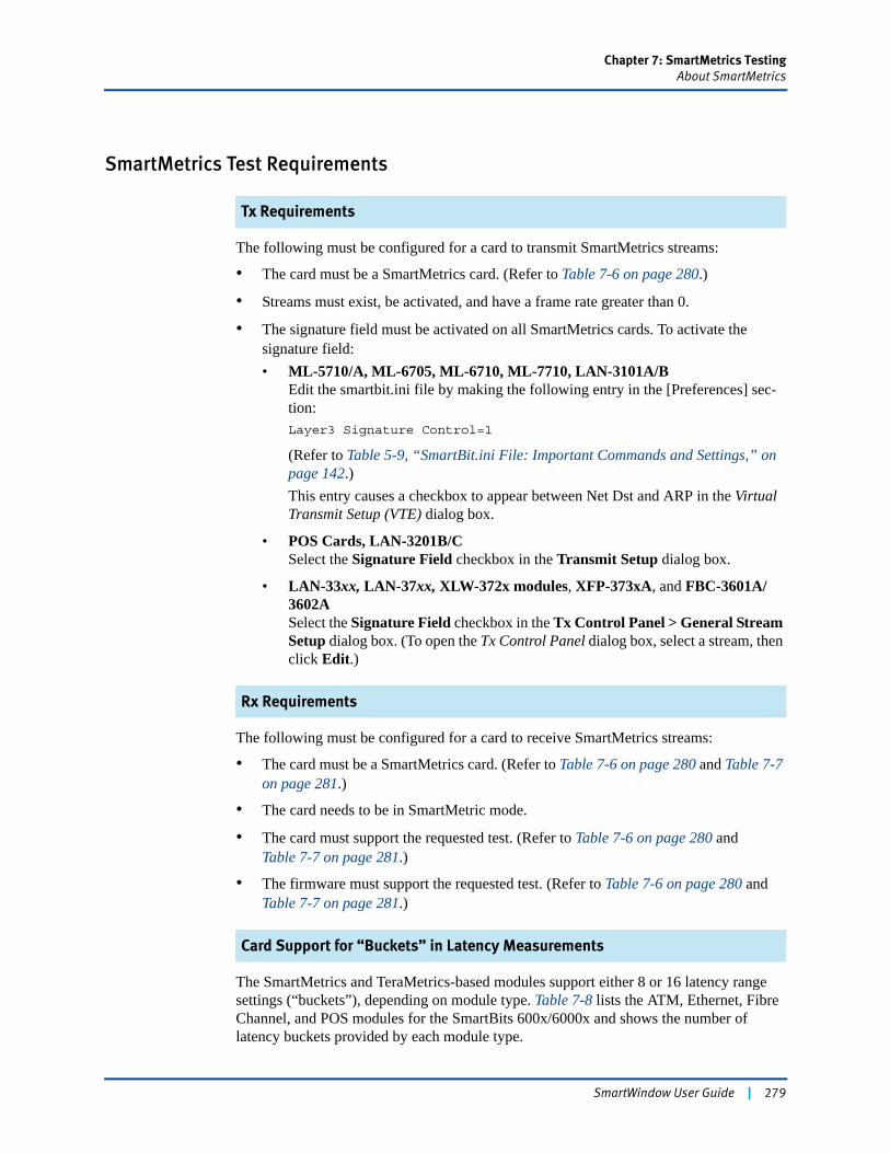
Chapter 7: SmartMetrics TestingAbout SmartMetrics
SmartMetrics Test Requirements
Tx Requirements
The following must be configured for a card to transmit SmartMetrics streams:
• The card must be a SmartMetrics card. (Refer to Table 7-6 on page 280.)
• Streams must exist, be activated, and have a frame rate greater than 0.
• The signature field must be activated on all SmartMetrics cards. To activate the signature field:• ML-5710/A, ML-6705, ML-6710, ML-7710, LAN-3101A/B
Edit the smartbit.ini file by making the following entry in the [Preferences] sec-tion:Layer3 Signature Control=1
(Refer to Table 5-9, “SmartBit.ini File: Important Commands and Settings,” on page 142.)This entry causes a checkbox to appear between Net Dst and ARP in the Virtual Transmit Setup (VTE) dialog box.
• POS Cards, LAN-3201B/CSelect the Signature Field checkbox in the Transmit Setup dialog box.
• LAN-33xx, LAN-37xx, XLW-372x modules, XFP-373xA, and FBC-3601A/3602ASelect the Signature Field checkbox in the Tx Control Panel > General Stream Setup dialog box. (To open the Tx Control Panel dialog box, select a stream, then click Edit.)
Rx Requirements
The following must be configured for a card to receive SmartMetrics streams:
• The card must be a SmartMetrics card. (Refer to Table 7-6 on page 280 and Table 7-7 on page 281.)
• The card needs to be in SmartMetric mode.
• The card must support the requested test. (Refer to Table 7-6 on page 280 and Table 7-7 on page 281.)
• The firmware must support the requested test. (Refer to Table 7-6 on page 280 and Table 7-7 on page 281.)
Card Support for “Buckets” in Latency Measurements
The SmartMetrics and TeraMetrics-based modules support either 8 or 16 latency range settings (“buckets”), depending on module type. Table 7-8 lists the ATM, Ethernet, Fibre Channel, and POS modules for the SmartBits 600x/6000x and shows the number of latency buckets provided by each module type.
SmartWindow User Guide | 279
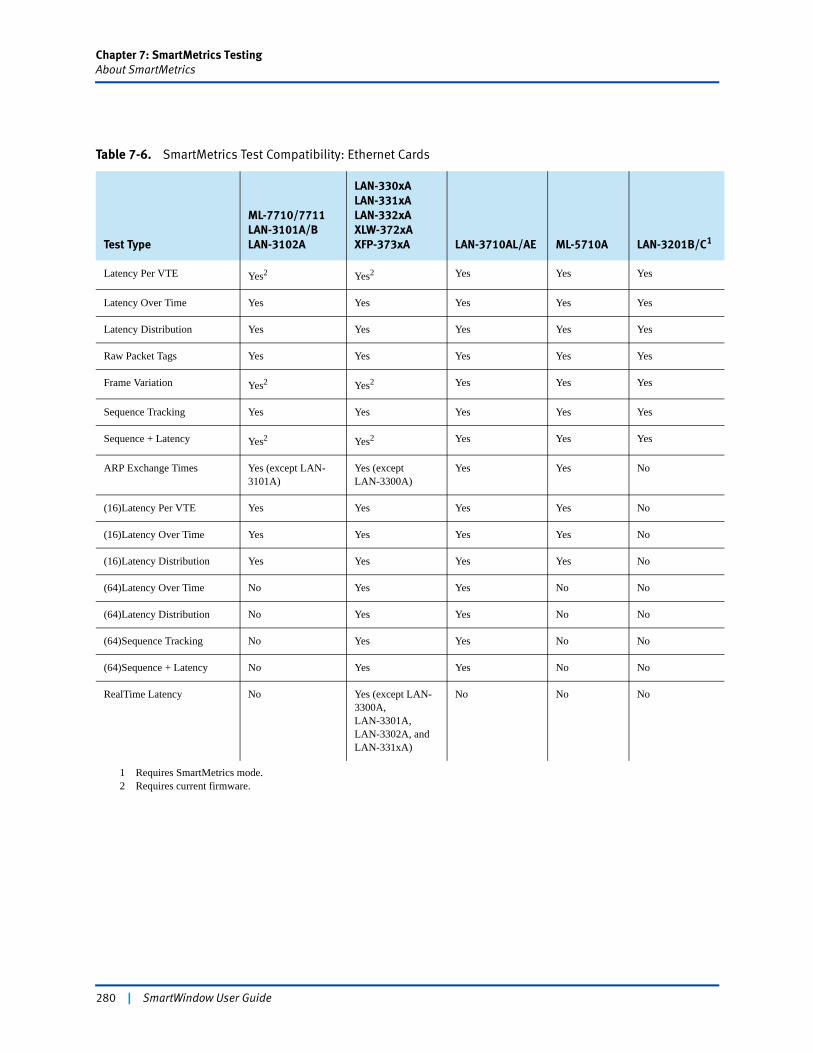
Chapter 7: SmartMetrics TestingAbout SmartMetrics
Table 7-6. SmartMetrics Test Compatibility: Ethernet Cards
Test Type
ML-7710/7711LAN-3101A/BLAN-3102A
LAN-330xALAN-331xALAN-332xAXLW-372xAXFP-373xA LAN-3710AL/AE ML-5710A LAN-3201B/C1
1 Requires SmartMetrics mode.
Latency Per VTE Yes2 Yes2
2 Requires current firmware.
Yes Yes Yes
Latency Over Time Yes Yes Yes Yes Yes
Latency Distribution Yes Yes Yes Yes Yes
Raw Packet Tags Yes Yes Yes Yes Yes
Frame Variation Yes2 Yes2 Yes Yes Yes
Sequence Tracking Yes Yes Yes Yes Yes
Sequence + Latency Yes2 Yes2 Yes Yes Yes
ARP Exchange Times Yes (except LAN-3101A)
Yes (exceptLAN-3300A)
Yes Yes No
(16)Latency Per VTE Yes Yes Yes Yes No
(16)Latency Over Time Yes Yes Yes Yes No
(16)Latency Distribution Yes Yes Yes Yes No
(64)Latency Over Time No Yes Yes No No
(64)Latency Distribution No Yes Yes No No
(64)Sequence Tracking No Yes Yes No No
(64)Sequence + Latency No Yes Yes No No
RealTime Latency No Yes (except LAN-3300A,LAN-3301A, LAN-3302A, and LAN-331xA)
No No No
280 | SmartWindow User Guide
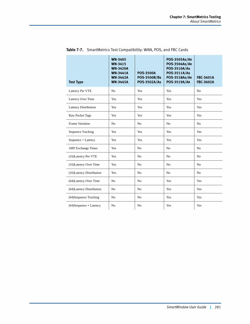
Chapter 7: SmartMetrics TestingAbout SmartMetrics
Table 7-7. SmartMetrics Test Compatibility: WAN, POS, and FBC Cards
Test Type
WN-3405WN-3415WN-3420AWN-3441AWN-3442AWN-3445A
POS-3500APOS-3500B/BsPOS-3502A/As
POS-3505As/AR
POS-3504As/AR
POS-3510A/AsPOS-3511A/AsPOS-3518As/AR
POS-3519A/AR
FBC-3601AFBC-3602A
Latency Per VTE No Yes Yes No
Latency Over Time Yes Yes Yes Yes
Latency Distribution Yes Yes Yes Yes
Raw Packet Tags Yes Yes Yes Yes
Frame Variation No No No No
Sequence Tracking Yes Yes Yes Yes
Sequence + Latency Yes Yes Yes Yes
ARP Exchange Times Yes No No No
(16)Latency Per VTE Yes No No No
(16)Latency Over Time Yes No No No
(16)Latency Distribution Yes No No No
(64)Latency Over Time No No Yes Yes
(64)Latency Distribution No No Yes Yes
(64)Sequence Tracking No No Yes Yes
(64)Sequence + Latency No No Yes Yes
SmartWindow User Guide | 281
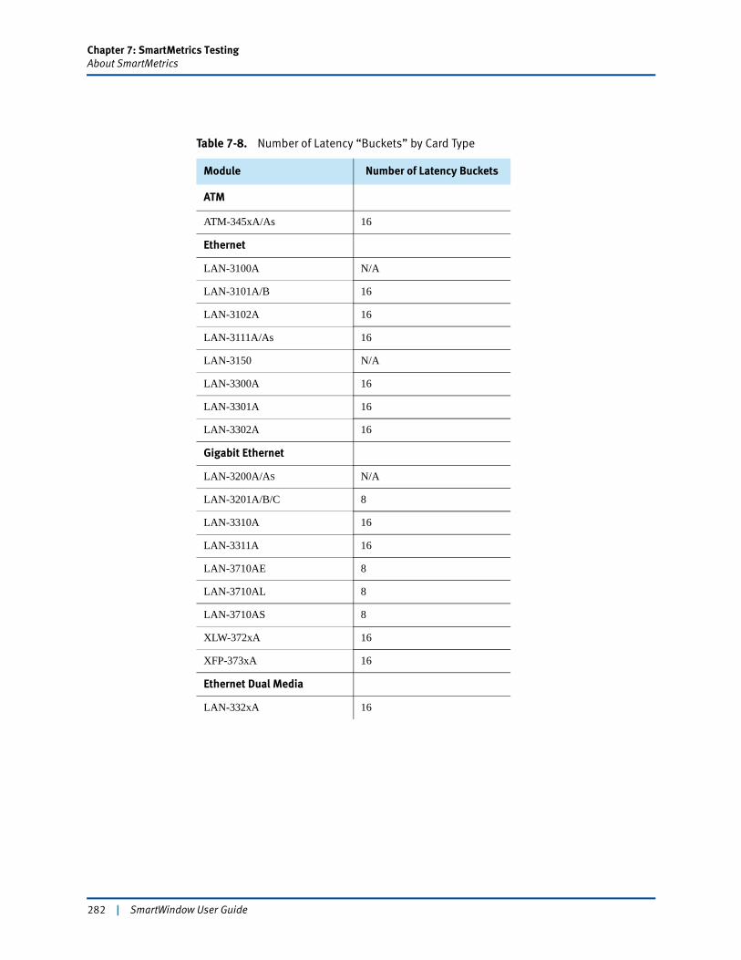
Chapter 7: SmartMetrics TestingAbout SmartMetrics
Table 7-8. Number of Latency “Buckets” by Card Type
Module Number of Latency Buckets
ATM
ATM-345xA/As 16
Ethernet
LAN-3100A N/A
LAN-3101A/B 16
LAN-3102A 16
LAN-3111A/As 16
LAN-3150 N/A
LAN-3300A 16
LAN-3301A 16
LAN-3302A 16
Gigabit Ethernet
LAN-3200A/AS N/A
LAN-3201A/B/C 8
LAN-3310A 16
LAN-3311A 16
LAN-3710AE 8
LAN-3710AL 8
LAN-3710AS 8
XLW-372xA 16
XFP-373xA 16
Ethernet Dual Media
LAN-332xA 16
282 | SmartWindow User Guide
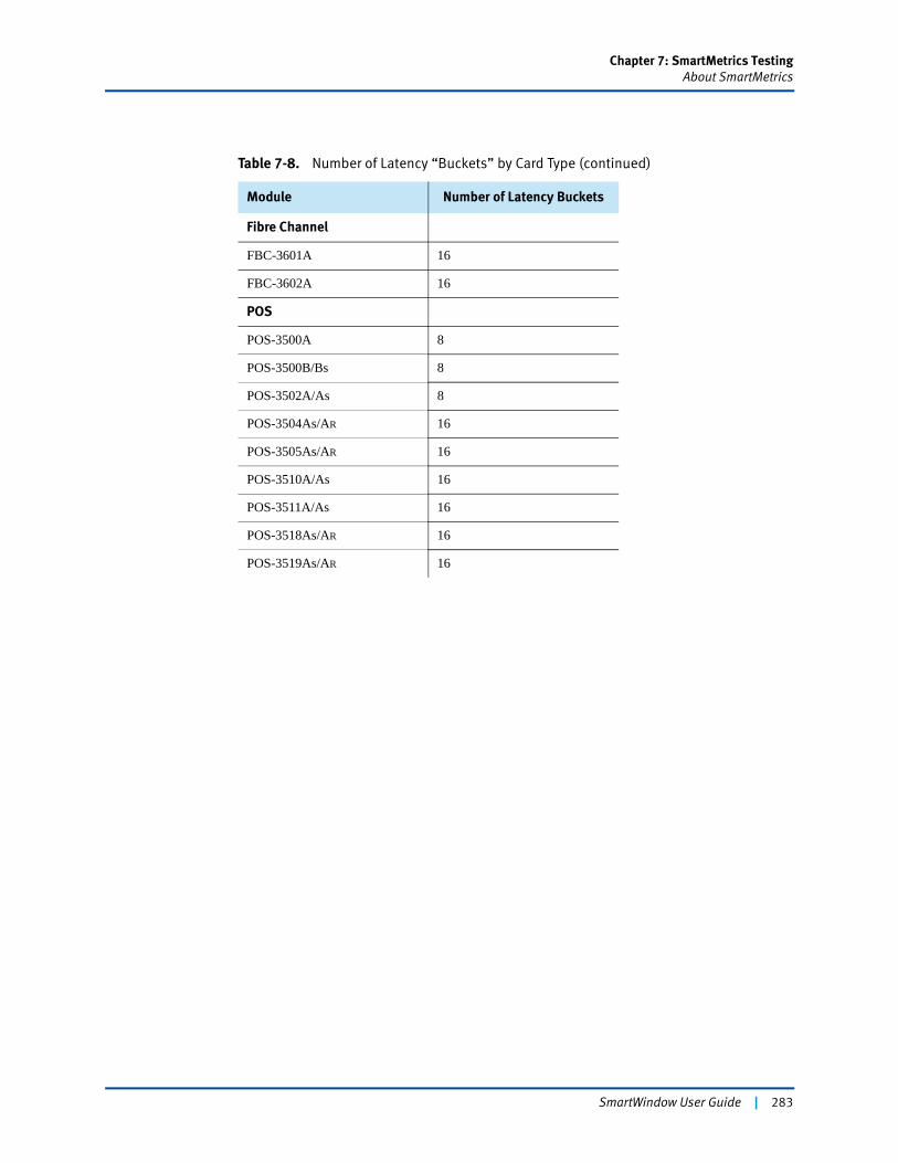
Chapter 7: SmartMetrics TestingAbout SmartMetrics
Module Number of Latency Buckets
Fibre Channel
FBC-3601A 16
FBC-3602A 16
POS
POS-3500A 8
POS-3500B/Bs 8
POS-3502A/As 8
POS-3504As/AR 16
POS-3505As/AR 16
POS-3510A/As 16
POS-3511A/As 16
POS-3518As/AR 16
POS-3519As/AR 16
Table 7-8. Number of Latency “Buckets” by Card Type (continued)
SmartWindow User Guide | 283
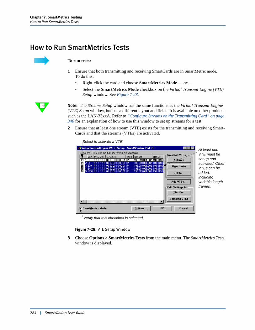
Chapter 7: SmartMetrics TestingHow to Run SmartMetrics Tests
How to Run SmartMetrics Tests
To run tests:
1 Ensure that both transmitting and receiving SmartCards are in SmartMetric mode.To do this:• Right-click the card and choose SmartMetrics Mode — or —• Select the SmartMetrics Mode checkbox on the Virtual Transmit Engine (VTE)
Setup window. See Figure 7-28.
Note: The Streams Setup window has the same functions as the Virtual Transmit Engine (VTE) Setup window, but has a different layout and fields. It is available on other products such as the LAN-33xxA. Refer to “Configure Streams on the Transmitting Card” on page 340 for an explanation of how to use this window to set up streams for a test.2 Ensure that at least one stream (VTE) exists for the transmitting and receiving Smart-
Cards and that the streams (VTEs) are activated.
Figure 7-28. VTE Setup Window
3 Choose Options > SmartMetrics Tests from the main menu. The SmartMetrics Tests window is displayed.
Verify that this checkbox is selected.
At least one VTE must be set up and activated. Other VTEs can be added, including variable length frames.
Select to activate a VTE.
284 | SmartWindow User Guide
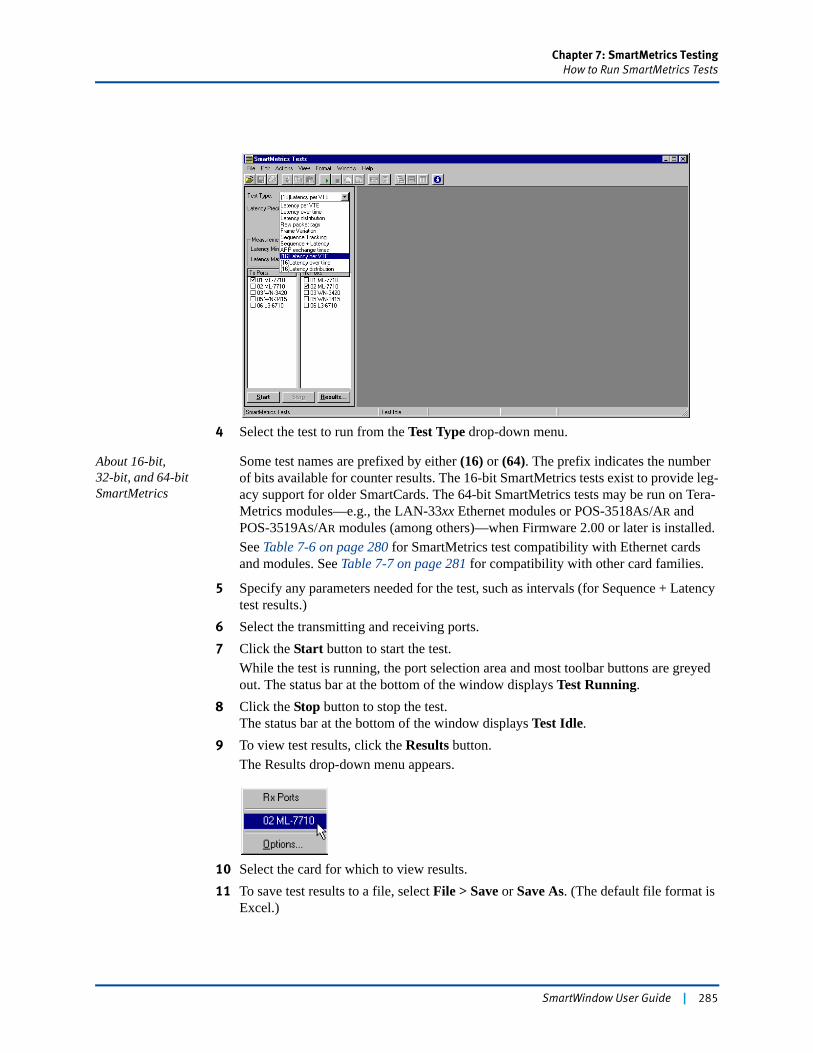
Chapter 7: SmartMetrics TestingHow to Run SmartMetrics Tests
4 Select the test to run from the Test Type drop-down menu.
About 16-bit,32-bit, and 64-bit SmartMetrics
Some test names are prefixed by either (16) or (64). The prefix indicates the number of bits available for counter results. The 16-bit SmartMetrics tests exist to provide leg-acy support for older SmartCards. The 64-bit SmartMetrics tests may be run on Tera-Metrics modules—e.g., the LAN-33xx Ethernet modules or POS-3518AS/AR and POS-3519AS/AR modules (among others)—when Firmware 2.00 or later is installed.See Table 7-6 on page 280 for SmartMetrics test compatibility with Ethernet cards and modules. See Table 7-7 on page 281 for compatibility with other card families.
5 Specify any parameters needed for the test, such as intervals (for Sequence + Latency test results.)
6 Select the transmitting and receiving ports.7 Click the Start button to start the test.
While the test is running, the port selection area and most toolbar buttons are greyed out. The status bar at the bottom of the window displays Test Running.
8 Click the Stop button to stop the test.The status bar at the bottom of the window displays Test Idle.
9 To view test results, click the Results button.The Results drop-down menu appears.
10 Select the card for which to view results.11 To save test results to a file, select File > Save or Save As. (The default file format is
Excel.)
SmartWindow User Guide | 285
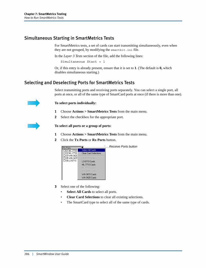
Chapter 7: SmartMetrics TestingHow to Run SmartMetrics Tests
Simultaneous Starting in SmartMetrics Tests
For SmartMetrics tests, a set of cards can start transmitting simultaneously, even when they are not grouped, by modifying the smartbit.ini file.
In the Layer 3 Tests section of the file, add the following lines:Simultaneous Start = 1
Or, if this entry is already present, ensure that it is set to 1. (The default is 0, which disables simultaneous starting.)
Selecting and Deselecting Ports for SmartMetrics Tests
Select transmitting ports and receiving ports separately. You can select a single port, all ports at once, or all of the same type of SmartCard ports at once (if there is more than one).
To select ports individually:
1 Choose Actions > SmartMetrics Tests from the main menu.2 Select the checkbox for the appropriate port.
To select all ports or a group of ports:
1 Choose Actions > SmartMetrics Tests from the main menu.2 Click the Tx Ports or Rx Ports button.
3 Select one of the following:• Select All Cards to select all ports.• Clear Card Selections to clear all existing selections.• The SmartCard type to select all of the same type of cards.
Receive Ports button
286 | SmartWindow User Guide
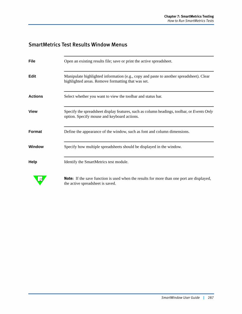
Chapter 7: SmartMetrics TestingHow to Run SmartMetrics Tests
SmartMetrics Test Results Window Menus
File Open an existing results file; save or print the active spreadsheet.
Edit Manipulate highlighted information (e.g., copy and paste to another spreadsheet). Clear highlighted areas. Remove formatting that was set.
Actions Select whether you want to view the toolbar and status bar.
View Specify the spreadsheet display features, such as column headings, toolbar, or Events Only option. Specify mouse and keyboard actions.
Format Define the appearance of the window, such as font and column dimensions.
Window Specify how multiple spreadsheets should be displayed in the window.
Help Identify the SmartMetrics test module.
Note: If the save function is used when the results for more than one port are displayed, the active spreadsheet is saved.
SmartWindow User Guide | 287
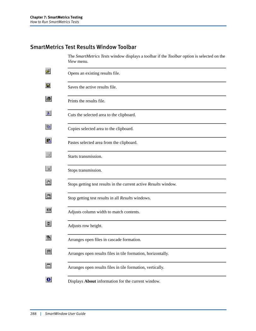
Chapter 7: SmartMetrics TestingHow to Run SmartMetrics Tests
SmartMetrics Test Results Window Toolbar
The SmartMetrics Tests window displays a toolbar if the Toolbar option is selected on the View menu.
Opens an existing results file.
Saves the active results file.
Prints the results file.
Cuts the selected area to the clipboard.
Copies selected area to the clipboard.
Pastes selected area from the clipboard.
Starts transmission.
Stops transmission.
Stops getting test results in the current active Results window.
Stop getting test results in all Results windows.
Adjusts column width to match contents.
Adjusts row height.
Arranges open files in cascade formation.
Arranges open results files in tile formation, horizontally.
Arranges open results files in tile formation, vertically.
Displays About information for the current window.
288 | SmartWindow User Guide
Chapter 7: SmartMetrics TestingHow to Optimize 16-bit Latency Testing
How to Optimize 16-bit Latency TestingKnowing the latency of a DUT before running a latency test may seem like a backwards approach to latency testing. However, the reason for latency tests is to verify the accuracy of your own latency estimates.
To optimize 16-bit latency testing:
1 Using your own latency estimates for a given DUT, run the Latency Distribution test as described in “(16) Latency Distribution Test” on page 291.
2 Review the results. Are the latency results distributed over a few buckets? If not:• Reset the precision to narrow the scale. For example, if the latency results fall
within two or three buckets toward the center at the default precision of 25.6 μs, change the precision factor and run the test again.
• Try using several frames of variable lengths (without FCS).3 Run the other latency tests once you are satisfied with the granularity of the Latency
Distribution test.
Refer to “SmartMetrics 16-bit Tests” on page 290 for additional information on setting up 16-bit tests.
SmartWindow User Guide | 289
Chapter 7: SmartMetrics TestingSmartMetrics 16-bit Tests
SmartMetrics 16-bit Tests16-bit SmartMetrics tests may generate incorrect results when numbers exceed the upper limit of a given histogram precision range. When this occurs, the results displayed are meaningless and the test should be run again within prescribed guidelines for a given DUT.
SmartMetrics tests use a 32-bit latency counter (whenever possible) to gather and display statistical data. Some earlier cards only had 16-bit counter capability for gathering statistical data. (This is a firmware limitation.) However, for cards that do support 32-bit counters, only 16 bits out of 32 bits are retrieved and displayed for the 16-bit test results. The retrievable 16-bit portion depends on the precision setting. By default, the precision is set to 25.6, a range of 25.6 μs to 1,677,696 μs (1.6 sec).
Important: This limitation only applies to the 16-bit tests. All 32-bit tests (such as Raw Packet Tag test, Sequence Tracking test, etc.) use the entire 32-bit counter contents and no precision setting is required.
The following SmartMetrics tests are affected:
• (16) Latency per VTE
• (16) Latency Over Time
• (16) Latency Distribution.
As an example, suppose the (16) Latency per VTE test is run, transmitting a single burst of frames from the SmartBits port 1 through a DUT back to port 2 on the SmartBits. Each frame latency is estimated at 100 μs. A single burst is sent, but when the test finishes, the cumulative latency does not fall between 25.6 μs – 1.68 sec. The test results are incorrect and the burst size needs to be recalculated in frames or the latency range needs to be changed.
For greater granularity, the expected latency for one frame should fall somewhere close to the lower limit of the target precision setting in Table 7-10 on page 294.
! Caution: When running 16-bit SmartMetrics tests at precision 6.5 msec, the maximum time of any 16-bit test is 429 sec.
290 | SmartWindow User Guide
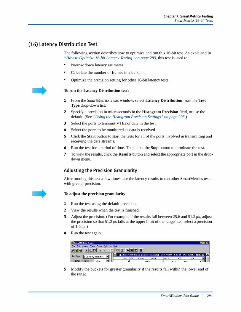
Chapter 7: SmartMetrics TestingSmartMetrics 16-bit Tests
(16) Latency Distribution Test
The following section describes how to optimize and run this 16-bit test. As explained in “How to Optimize 16-bit Latency Testing” on page 289, this test is used to:
• Narrow down latency estimates.
• Calculate the number of frames in a burst.
• Optimize the precision setting for other 16-bit latency tests.
To run the Latency Distribution test:
1 From the SmartMetrics Tests window, select Latency Distribution from the Test Type drop-down list.
2 Specify a precision in microseconds in the Histogram Precision field, or use the default. (See “Using the Histogram Precision Settings” on page 293.)
3 Select the ports to transmit VTEs of data in the test.4 Select the ports to be monitored as data is received.5 Click the Start button to start the tests for all of the ports involved in transmitting and
receiving the data streams.6 Run the test for a period of time. Then click the Stop button to terminate the test.7 To view the results, click the Results button and select the appropriate port in the drop-
down menu.
Adjusting the Precision Granularity
After running this test a few times, use the latency results to run other SmartMetrics tests with greater precision.
To adjust the precision granularity:
1 Run the test using the default precision.2 View the results when the test is finished.3 Adjust the precision. (For example, if the results fall between 25.6 and 51.2 μs, adjust
the precision so that 51.2 μs falls at the upper limit of the range, i.e., select a precision of 1.6 μs.)
4 Run the test again.
5 Modify the buckets for greater granularity if the results fall within the lower end of the range.
SmartWindow User Guide | 291
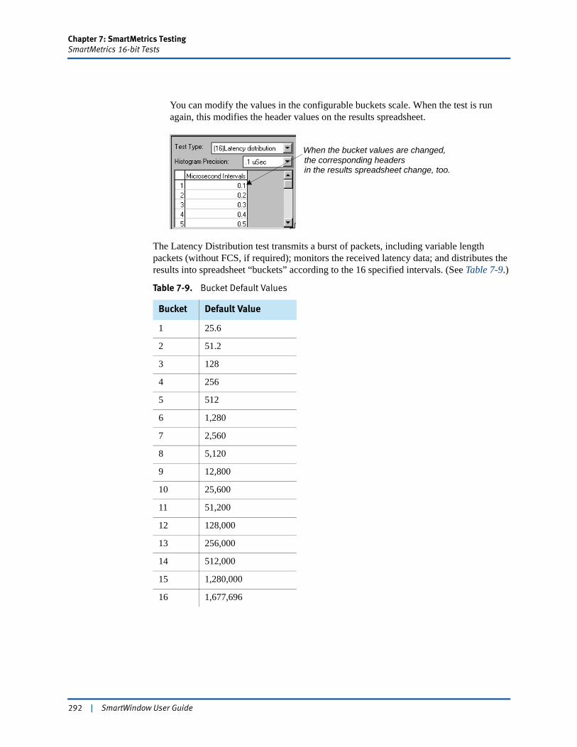
Chapter 7: SmartMetrics TestingSmartMetrics 16-bit Tests
You can modify the values in the configurable buckets scale. When the test is run again, this modifies the header values on the results spreadsheet.
The Latency Distribution test transmits a burst of packets, including variable length packets (without FCS, if required); monitors the received latency data; and distributes the results into spreadsheet “buckets” according to the 16 specified intervals. (See Table 7-9.)
Table 7-9. Bucket Default Values
Bucket Default Value
1 25.6
2 51.2
3 128
4 256
5 512
6 1,280
7 2,560
8 5,120
9 12,800
10 25,600
11 51,200
12 128,000
13 256,000
14 512,000
15 1,280,000
16 1,677,696
When the bucket values are changed,the corresponding headersin the results spreadsheet change, too.
292 | SmartWindow User Guide
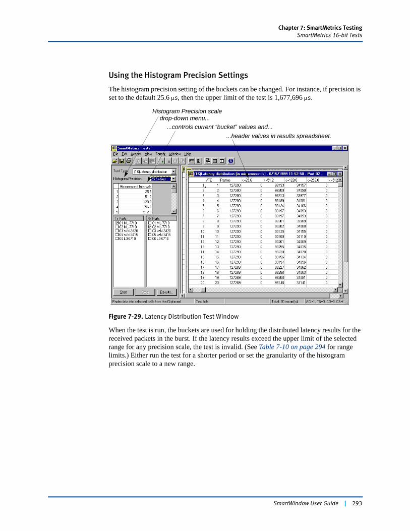
Chapter 7: SmartMetrics TestingSmartMetrics 16-bit Tests
Using the Histogram Precision Settings
The histogram precision setting of the buckets can be changed. For instance, if precision is set to the default 25.6 μs, then the upper limit of the test is 1,677,696 μs.
Figure 7-29. Latency Distribution Test Window
When the test is run, the buckets are used for holding the distributed latency results for the received packets in the burst. If the latency results exceed the upper limit of the selected range for any precision scale, the test is invalid. (See Table 7-10 on page 294 for range limits.) Either run the test for a shorter period or set the granularity of the histogram precision scale to a new range.
...controls current “bucket” values and......header values in results spreadsheet.
Histogram Precision scaledrop-down menu...
SmartWindow User Guide | 293
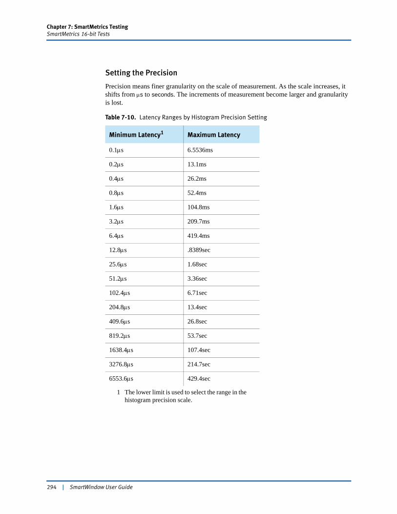
Chapter 7: SmartMetrics TestingSmartMetrics 16-bit Tests
Setting the Precision
Precision means finer granularity on the scale of measurement. As the scale increases, it shifts from μs to seconds. The increments of measurement become larger and granularity is lost.
Table 7-10. Latency Ranges by Histogram Precision Setting
Minimum Latency1
1 The lower limit is used to select the range in the histogram precision scale.
Maximum Latency
0.1μs 6.5536ms
0.2μs 13.1ms
0.4μs 26.2ms
0.8μs 52.4ms
1.6μs 104.8ms
3.2μs 209.7ms
6.4μs 419.4ms
12.8μs .8389sec
25.6μs 1.68sec
51.2μs 3.36sec
102.4μs 6.71sec
204.8μs 13.4sec
409.6μs 26.8sec
819.2μs 53.7sec
1638.4μs 107.4sec
3276.8μs 214.7sec
6553.6μs 429.4sec
294 | SmartWindow User Guide
Chapter 7: SmartMetrics TestingSmartMetrics 16-bit Tests
(16) Latency per VTE Test
The Latency per VTE test checks the latency for each active VTE of the transmitting port. Before running this test, refer to “SmartMetrics 16-bit Tests” on page 290.
SmartWindow monitors the received data and displays these results:
• Port – Transmitting port number
• VTE – Transmitting VTE stream number
• Frames – Total number of packets received
• Minimum, Maximum, Average – Minimum, maximum, and average latency (time in microseconds, between time sent and time received).
To run the Latency per VTE test:
1 Select Latency per VTE from the Test Type field drop-down list.2 Specify a precision in microseconds in the Latency Precision field, or use the default.3 Select the ports to transmit VTEs of data in the test. 4 Select the ports to receive data.5 Run the test for a specified period of time. Then click the Stop button to terminate the
test.6 Click the Results button and select the appropriate port in the drop-down menu to
view the results.The values show the latency of all received packets in the burst and are dependent on the precision setting.
SmartWindow User Guide | 295
Chapter 7: SmartMetrics TestingSmartMetrics 16-bit Tests
(16) Latency Over Time Test
For this test, specify a time period (e.g., 1 msec increments). The test stores results in up to 4,000 data collectors. The test records all packets received with timestamp data and calculates the minimum or average latency for all currently active VTEs. The test also records data for discard eligible packets. Before running this test, refer to “SmartMetrics 16-bit Tests” on page 290.
SmartWindow monitors the received data and displays these results for all packets and as well as separate columns for discard eligible packets:• MilliSec – The time interval over which the data was gathered• Frames – Total number of packets received• Minimum, Average – Minimum or average latency (time in microseconds, between
time sent and time received).
To run the Latency Over Time test:
1 Select Latency over time from the Test Type field drop-down menu.2 Specify the precision in microseconds in the Latency Precision field, or use the
default.3 Specify the latency (minimum or average).4 Select the ports to transmit VTEs of data in the test. 5 Select the ports to be monitored as data is received.6 Click the Start button to start the tests for all of the ports involved in transmitting and
receiving the data streams.7 Run the test for a period of time. Then click Stop to terminate the test.8 Click the Results button and select the appropriate port in the drop-down menu to
view the results. Example: If the test is set for a time interval of 5,000 msec and the test runs for 1 minute, the results spreadsheet contains 12 rows showing the number of packets plus minimum, maximum, and average latency during that time period.
296 | SmartWindow User Guide
Chapter 7: SmartMetrics TestingOther SmartMetrics Tests
Other SmartMetrics TestsRefer to “Required Steps for SmartMetrics (Layer 3) Testing” on page 238 to set up Smartmetrics tests and “How to Run SmartMetrics Tests” on page 284 to run those tests.
Sequence Tracking Test
The Sequence Tracking test checks if any packets were dropped (not received) or received out of sequence for each active VTE.
SmartWindow monitors the received data and displays results for:
• Port - Transmitting port number
• VTE - Transmitting VTE stream number
• Frames -Total number of packets received
• InSeq - Number of packets received in sequence.
To run the Sequence Tracking test:
1 Select Sequence Tracking from the Test Type field drop-down list.2 Select the ports to transmit VTEs of data in the test. 3 Select the ports to be monitored as data is received.4 Click the Start button to start the tests for all of the ports involved in transmitting and
receiving the data streams.5 Run the test for a period of time. Then click the Stop button to terminate the test.6 View the results by clicking the Results button.
Sequence + Latency Test
The Sequence + Latency test checks packet tags to verify that packets transmitted by other SmartMetrics SmartCards are received correctly, whether the packets are received in the correct sequence, and whether there are duplicate or missing packets. This test is a combination of the Sequence Tracking, Latency per VTE, and Latency Distribution tests.
The Sequence + Latency test is run per VTE stream. SmartWindow reports test results for each active VTE stream separately. For the duration of the test, the results show the minimum, maximum, and average latency in microseconds for each VTE stream received from each port transmitting to the receiving port.
Important: This test can be used with ML-7710 SmartCards that have Firmware Version 2.00 or higher.
SmartWindow User Guide | 297
Chapter 7: SmartMetrics TestingOther SmartMetrics Tests
SmartWindow monitors the received data and displays results for:
• Port - Transmitting port number
• VTE - Transmitting VTE stream number
• Frames -Total number of packets received
• InSeq - Number of packets received in sequence
• Minimum, Maximum, Average – Minimum, maximum, and average latency (time in microseconds, between time sent and time received)
• 16 Latency Intervals - Latency distribution for default or user-specified times in microseconds.
Note: For this release, use a rate less than 133,000 per second. Set the rate in the Interpacket Gap pane of the Transmit Setup dialog box.
To run the Sequence + Latency test:
1 Select Sequence + Latency from the Test Type field drop-down list. 2 Enter a time in microseconds for an interval and press Enter, or use the default times
that are displayed for the test. These times are used to create a histogram of packets received within the specified time intervals. Up to 16 counter ranges can be specified, incrementing each histogram counter for each packet received within the range of the counter. Each counter can be specified in bit times (e.g., 0.1 μsec).
3 Select which time intervals to use for the test. If specific intervals are not selected, each of the 16 intervals is used.
4 Select the ports to transmit VTEs of data in the test. (Only SmartMetrics SmartCards appear.)
5 Select the ports to be monitored as data is received.6 Click the Start button to start the tests for all of the ports involved in transmitting and
receiving the VTE data streams.7 Run the test for a period of time. Then click the Stop button to terminate the test.8 View the results by clicking the Results button.9 Save the results to an Excel or Layer 3 Editor file, or copy and paste them to other
applications.
Real Time Latency Test
The Real Time Latency test generates three measurable components in a real-time environment: average latency, total number of packets, and values for all 16 buckets. This test is available for these specific LAN modules:
• LAN-3306A
298 | SmartWindow User Guide
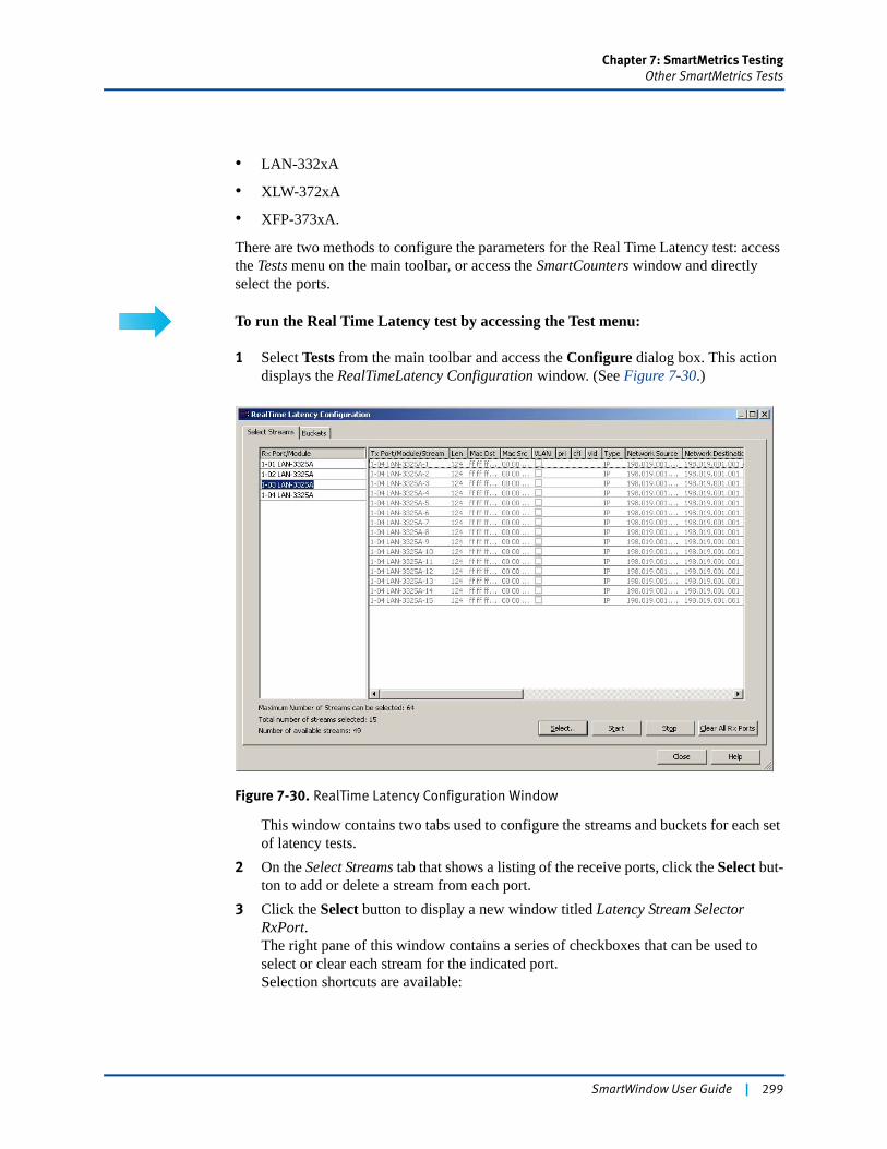
Chapter 7: SmartMetrics TestingOther SmartMetrics Tests
• LAN-332xA
• XLW-372xA
• XFP-373xA.
There are two methods to configure the parameters for the Real Time Latency test: access the Tests menu on the main toolbar, or access the SmartCounters window and directly select the ports.
To run the Real Time Latency test by accessing the Test menu:
1 Select Tests from the main toolbar and access the Configure dialog box. This action displays the RealTimeLatency Configuration window. (See Figure 7-30.)
Figure 7-30. RealTime Latency Configuration Window
This window contains two tabs used to configure the streams and buckets for each set of latency tests.
2 On the Select Streams tab that shows a listing of the receive ports, click the Select but-ton to add or delete a stream from each port.
3 Click the Select button to display a new window titled Latency Stream Selector RxPort.The right pane of this window contains a series of checkboxes that can be used to select or clear each stream for the indicated port.Selection shortcuts are available:
SmartWindow User Guide | 299
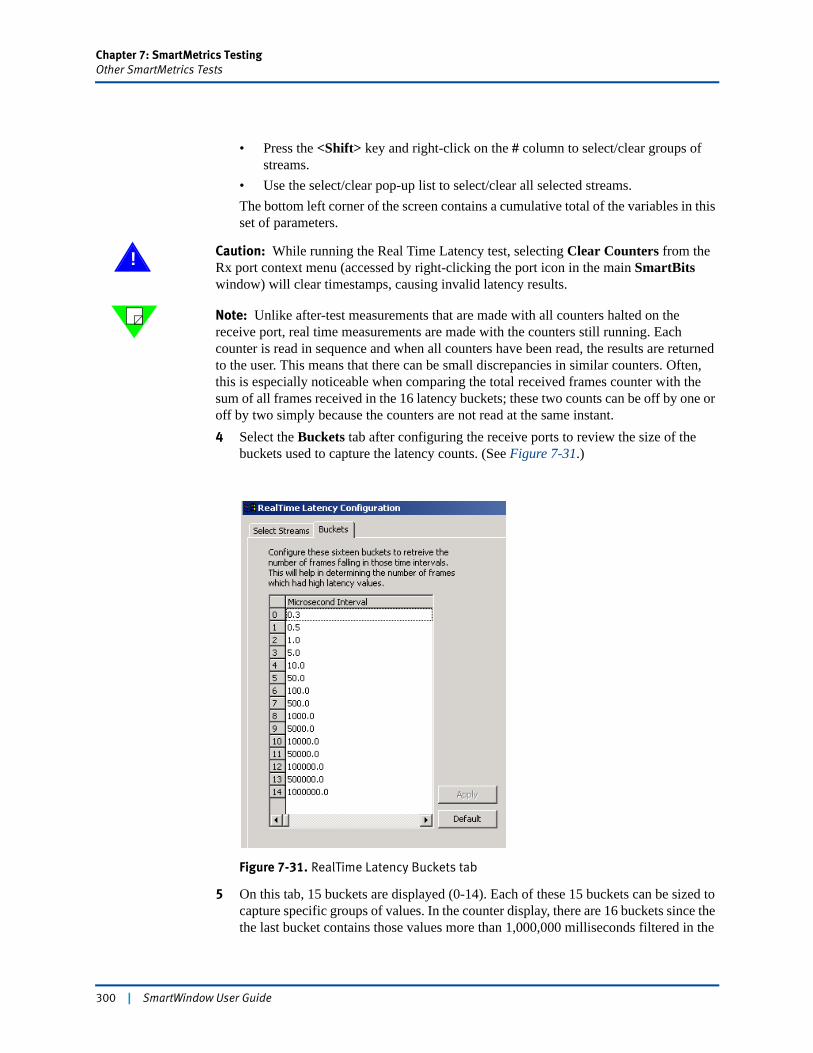
Chapter 7: SmartMetrics TestingOther SmartMetrics Tests
• Press the <Shift> key and right-click on the # column to select/clear groups of streams.
• Use the select/clear pop-up list to select/clear all selected streams.The bottom left corner of the screen contains a cumulative total of the variables in this set of parameters.
! Caution: While running the Real Time Latency test, selecting Clear Counters from the Rx port context menu (accessed by right-clicking the port icon in the main SmartBits window) will clear timestamps, causing invalid latency results.
Note: Unlike after-test measurements that are made with all counters halted on the receive port, real time measurements are made with the counters still running. Each counter is read in sequence and when all counters have been read, the results are returned to the user. This means that there can be small discrepancies in similar counters. Often, this is especially noticeable when comparing the total received frames counter with the sum of all frames received in the 16 latency buckets; these two counts can be off by one or off by two simply because the counters are not read at the same instant.4 Select the Buckets tab after configuring the receive ports to review the size of the
buckets used to capture the latency counts. (See Figure 7-31.)
Figure 7-31. RealTime Latency Buckets tab
5 On this tab, 15 buckets are displayed (0-14). Each of these 15 buckets can be sized to capture specific groups of values. In the counter display, there are 16 buckets since the the last bucket contains those values more than 1,000,000 milliseconds filtered in the
300 | SmartWindow User Guide
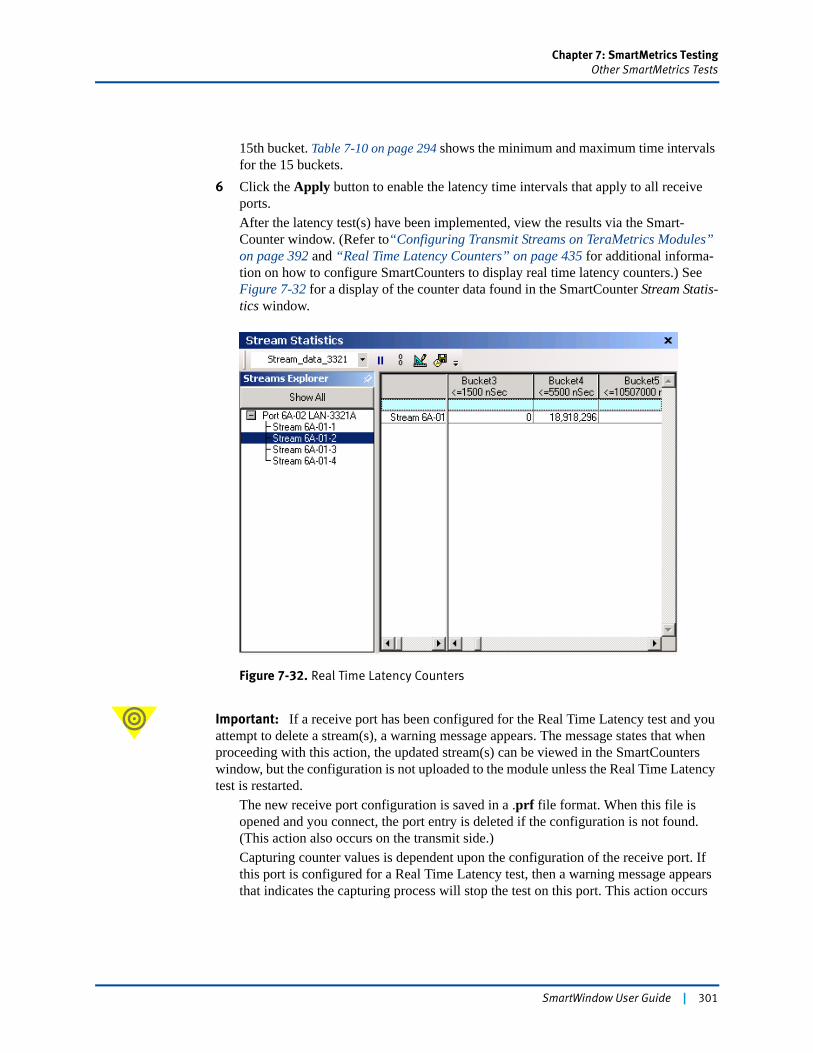
Chapter 7: SmartMetrics TestingOther SmartMetrics Tests
15th bucket. Table 7-10 on page 294 shows the minimum and maximum time intervals for the 15 buckets.
6 Click the Apply button to enable the latency time intervals that apply to all receive ports.After the latency test(s) have been implemented, view the results via the Smart-Counter window. (Refer to“Configuring Transmit Streams on TeraMetrics Modules” on page 392 and “Real Time Latency Counters” on page 435 for additional informa-tion on how to configure SmartCounters to display real time latency counters.) See Figure 7-32 for a display of the counter data found in the SmartCounter Stream Statis-tics window.
Figure 7-32. Real Time Latency Counters
Important: If a receive port has been configured for the Real Time Latency test and you attempt to delete a stream(s), a warning message appears. The message states that when proceeding with this action, the updated stream(s) can be viewed in the SmartCounters window, but the configuration is not uploaded to the module unless the Real Time Latency test is restarted.
The new receive port configuration is saved in a .prf file format. When this file is opened and you connect, the port entry is deleted if the configuration is not found. (This action also occurs on the transmit side.)Capturing counter values is dependent upon the configuration of the receive port. If this port is configured for a Real Time Latency test, then a warning message appears that indicates the capturing process will stop the test on this port. This action occurs
SmartWindow User Guide | 301
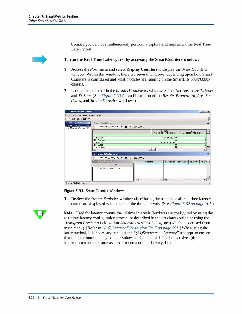
Chapter 7: SmartMetrics TestingOther SmartMetrics Tests
because you cannot simultaneously perform a capture and implement the Real Time Latency test.
To run the Real Time Latency test by accessing the SmartCounters window:
1 Access the Port menu and select Display Counters to display the SmartCounters window. Within this window, there are several windows, depending upon how Smart-Counters is configured and what modules are running on the SmartBits 600x/6000x chassis.
2 Locate the menu bar in the Results Framework window. Select Actions to see Tx Start and Tx Stop. (See Figure 7-33 for an illustration of the Results Framework, Port Sta-tistics, and Stream Statistics windows.)
Figure 7-33. SmartCounter Windows
3 Review the Stream Statistics window after/during the test, since all real time latency counts are displayed within each of the time intervals. (See Figure 7-32 on page 301.)
Note: Used for latency counts, the 16 time intervals (buckets) are configured by using the real time latency configuration procedure described in the previous section or using the Histogram Precision field within SmartMetrics Test dialog box (which is accessed from main menu). [Refer to “(16) Latency Distribution Test” on page 291.] When using the latter method, it is necessary to select the “(64)Sequence + Latency” test type to ensure that the maximum latency counter values can be obtained. The bucket sizes (time intervals) remain the same as used for conventional latency data.
302 | SmartWindow User Guide
Chapter 7: SmartMetrics TestingOther SmartMetrics Tests
Raw Packet Tags Test
In Layer 3, VTE streams contain a 16-byte packet tag field in each transmitted packet. This tag is inserted at the end of the packet and consists of packet sequence number, source VTE stream, destination VTE stream, and timestamp. This function is used to determine transit latency and, in conjunction with the protocol VFD, to facilitate mesh tests of components such as routers.
In the Raw Packet Tags test, packets are stored and sent directly to SmartWindow without any calculations or filtering performed on the VTE stream tags received. The test can store up to 4,000 packet tags. The results spreadsheet for the test displays one line of information for every tagged packet of each VTE.
Note: The Raw Packets test retrieves and displays a maximum of 16,300 packets.
SmartWindow monitors the received data and displays these results for each packet of each VTE:
• Port – The port on which the packet was received.
• VTE – The number of the VTE identifying the VTE source of the stream.
• Sequence – The packet sequence number, which is incremented for each packet transmitted. Sequence numbers are maintained independently for each destination VTE stream. The numbers are reset to zero whenever the card is started.
• TxTime – The timestamp indicating when the packet was transmitted. It is the timestamp of transmit time for a packet to 100 ns resolution. (This timestamp is added by the transmit hardware and represents the actual time the packet exited the card rather than the time the packet was prepared for transmission.) It is an absolute number representing the clock tick at the time of transmission. It is relative to Rx Time.
• RxTime – The timestamp of when the packet was received. It is an absolute number representing the clock tick at the time of receipt. It is relative to Tx Time.
• Delta – The amount of change between Tx Time and Rx Time.
To run the Raw Packet Tags test:
1 Select Raw packet tags from the Test Type field drop-down list.2 Select the ports to transmit VTEs of data in the test. 3 Select the ports to be monitored as data is received.4 Click the Start button to start the tests for all of the ports involved in transmitting and
receiving the data streams.5 Run the test for a period of time. Then click the Stop button to terminate the test.6 View the results by clicking the Results button.
The raw data is shown in the spreadsheet and can be copied or saved for detailed pro-cessing elsewhere.
SmartWindow User Guide | 303
Chapter 7: SmartMetrics TestingOther SmartMetrics Tests
ARP Exchange Times Test
This is a test of Address Resolution Protocol (ARP) response. For each VTE stream that uses IP or UDP, the card transmits an ARP request. The timestamp of the request and its response is stored per stream. Information is stored for each active stream.
Note: Currently this test is not supported on the LAN-3300A/LAN-3301A module.
For each VTE (stream), SmartWindow displays these results:
• DestMAC – The MAC address of the connected Device Under Test (DUT).
• ReplyTime – The time in microseconds before an ARP response is received.
To run the ARP Exchange Times test:
1 Select ARP Exchange Times from the Test Type field drop-down list.2 Select the ports to transmit VTEs of data in the test. 3 Select the ports to be monitored as data is received.4 Click the Start button to start the tests for all of the ports involved in transmitting and
receiving the data streams.5 Run the test for a period of time. Then click the Stop button to terminate the test.6 View the results by clicking the Results button.
Frame Variation Test
Packets that were transmitted at regularly spaced intervals can be delayed once they enter the network and arrive at varying intervals, due to factors such as jitter or device buffering.
This test measures variations in how soon one packet follows another in a VTE stream. For example, it measures the time interval between packets 1 and 2, then between packets 2 and 3, etc., as the packets arrive at the DUT. This test plots the number of packets that arrive within each of the 16 user-specified time intervals.
SmartWindow monitors the received data and displays these results for each packet of each VTE:
• Port – The port on which the packet was received.
• VTE – The number of the VTE identifying the VTE source of the stream.
• Frames – Total number of packets received.
• 16 Intervals – Time interval default or user-specified times in microseconds by which to track packet arrival times.
304 | SmartWindow User Guide

Chapter 7: SmartMetrics TestingOther SmartMetrics Tests
To run the Frame Variation test:
1 Select Frame Variation from the Test Type field drop-down list.2 Enter a time in microseconds for an interval and press the Enter key, or use the
default times that are displayed for the test. These times are used to create a histogram of packets received within the specified time intervals.You can specify up to 16 counter ranges, incrementing each histogram counter for each packet received within the range of the counter. Each counter can be specified in bit times (e.g., 0.1 μsec).
3 Select which time intervals to use for the test. If no intervals are selected, each of the 16 is used.
4 Select the ports to transmit VTEs of data in the test. (Only SmartMetrics SmartCards appear.)
5 Select the ports to be monitored as data is received.6 Click the Start button to start the tests for all of the ports involved in transmitting and
receiving the VTE data streams.7 Run the test for a period of time. Then click the Stop button to terminate the test.8 View the results by clicking the Results button.
SmartWindow User Guide | 305
Chapter 7: SmartMetrics TestingSmartMetrics Test Results
SmartMetrics Test ResultsThe SmartMetrics tests emulate live network traffic. They provide information about the relationships and timing of frames so the functionality and performance of a device under load can be evaluated. They dynamically track data per stream and change in latency. Since the results are presented in spreadsheet format, totals for a single SmartCard can be obtained. The stream-based SmartMetrics test results include:
• Sequence tracking
• Sequence + Latency (both 16- and 32-bit tests; does not apply to ML-7710 SmartCard)
• (16) Latency per VTE
• (16) Latency distribution
• (16) Latency over time
• ARP exchange times
• Raw packet tags
• Frame variation.
The (16) preceding some test options refers to the number of bits available for counter results. Tests not marked with (16) contain 32-bit counters. Before running the 16-bit counter tests, refer to “SmartMetrics 16-bit Tests” on page 290.
Latency in SmartMetrics Test Results
All of the SmartMetrics latency tests measure the difference between transmit and arrival time. Specifically, this is the difference between the time at which a tagged byte leaves the transmitting port and the time at which that byte arrives at the receiving port. However, each test result differs in how it measures latency—per VTE, over time, or by distribution. The Sequence + Latency tests combine three tests: sequence tracking, latency per VTE, and latency distribution.
Cut Through and Store and Forward Devices
Latency test results are typically used to measure the performance of "cut through" devices. Measurement of latency through one or more "store and forward" switches can be calculated by adding the time to transfer any remaining bytes out of the transmitting port.
Cut through devices begin retransmission after receiving packet headers. This increases performance over store and forward devices. Latency of these devices is described above.
Store and forward devices receive a complete packet on the input port before beginning transmission on the output port. For these devices, the latency is defined as the difference between the time the last byte leaves the transmitting device and the time at which the first byte arrives at the destination device.
306 | SmartWindow User Guide
Chapter 7: SmartMetrics TestingSmartMetrics Test Results
The results are presented to cover both possibilities. A result of NO is shown in the store and forward column if the system is able to detect the type of DUT as a cut-through switch.
Interpreting SmartMetrics Test Results
SmartWindow places test results for a receiving port into a spreadsheet that can be viewed from within the SmartMetrics Tests window. Use the SmartMetrics Test window toolbar buttons or the menu options to modify the spreadsheet format and selectively display information as you can with traditional spreadsheet applications.
Timestamps - Tests that use latency histograms (Sequence + Latency and Latency Over Time) utilize a timestamp of when the packet was transmitted. The timestamp is the transmit time for a packet to a 100 ns resolution. The transmit hardware adds this time stamp. It represents the actual time the packet exited the card rather than the time the packet was prepared for transmission. It is an absolute number representing the clock tick at the time of transmission.
Management Frames – Management frames (RIP and SNMP) can be added to any SmartMetrics tests (per RFC 1944) from the Port Setup window. Management frames are relatively low rate streams containing authentic packets that are designed to inject management and routing control traffic into a test stream.
Note: If results are displayed for more than one port at a time, when a file is saved, only the active spreadsheet is saved to the file.
Viewing SmartMetrics Test Results (Histograms)
To view results for a single destination SmartCard:
1 Click the Results button, or select Actions > Get Results from the menu.2 Select the port for which to view results.
A spreadsheet containing the results appears in the right pane of the window.3 Specify any required formatting or window elements using the toolbar or menu bar
options.
To view results for more than one port, repeat these steps. Spreadsheets for subsequent ports that are selected display in the window according to which command is in effect on the toolbar.
To change the order in which the results are retrieved:
1 Click the Results button, then choose Options from the pop-up menu. 2 From the SmartMetrics Test Options dialog box, select the port to reorder the test
results.
SmartWindow User Guide | 307

Chapter 7: SmartMetrics TestingDetailed Tracking and Statistical Results
Detailed Tracking and Statistical ResultsThis section contains a sample configuration procedure for the latency and sequence tracking tests used to inspect the raw packet results via data capture. Information regarding performance of Latency and Sequence Tracking tests, inspection of raw packets, plus use of triggers and capture is included.
The Latency and Sequence Tracking tests provide valuable statistical data for performance analysis of the Layer 3 switch/router.
To perform Latency and Sequence Tracking tests:
1 Confirm that all links are active.
In this example, the following parameters are set up using 20 streams for ports 1 and 2:• Transmit setup: continuous mode, 9.6 μsec interpacket gap for 100% utilization• Frame length (without FCS) for all streams: 60
2 Choose Actions > Layer 3 Send ARP Requests.3 To run SmartMetrics tests on traffic from port 1 to port 2, choose Options > Smart-
Metrics Tests.
Link displayed on the SmartCard indicates an active link to the DUT.
308 | SmartWindow User Guide

Chapter 7: SmartMetrics TestingDetailed Tracking and Statistical Results
Sequence tracking
4 Choose Test Type > Sequence Tracking, select checkboxes for Tx port 01 and Rx port 02, then click the Start button at the bottom of the window. After several sec-onds, click the Stop button. Then click the Results button and select the receive card (port 02).
5 To set a lighter load and determine the rate at which there is little or no packet loss, right-click port 1, select Transmit Setup, and click the This Port button.
6 In the Interpacket Gap pane, select % Utilization in the Units field, then enter 90 in the Rate field. Click OK.
7 Click OK again to close the Transmit Setup window.
SmartWindow User Guide | 309
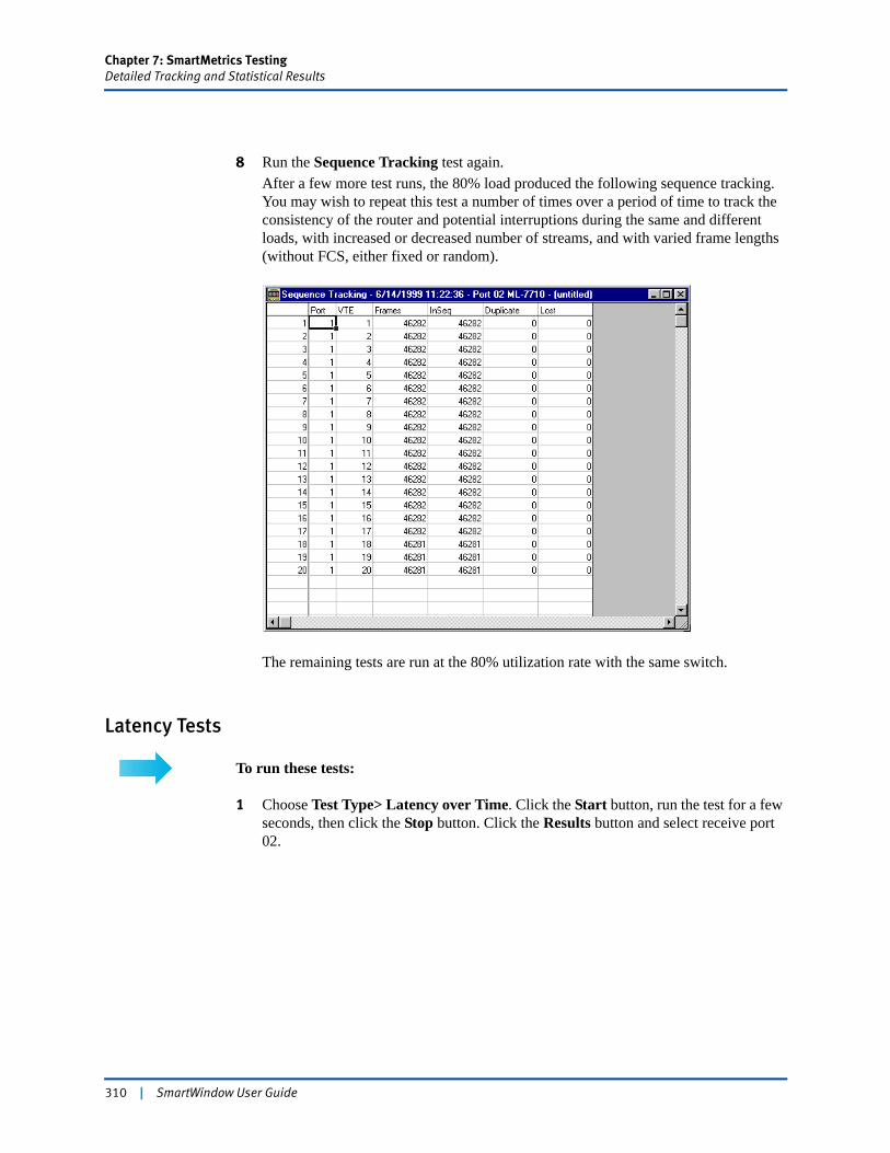
Chapter 7: SmartMetrics TestingDetailed Tracking and Statistical Results
8 Run the Sequence Tracking test again.After a few more test runs, the 80% load produced the following sequence tracking. You may wish to repeat this test a number of times over a period of time to track the consistency of the router and potential interruptions during the same and different loads, with increased or decreased number of streams, and with varied frame lengths (without FCS, either fixed or random).
The remaining tests are run at the 80% utilization rate with the same switch.
Latency Tests
To run these tests:
1 Choose Test Type> Latency over Time. Click the Start button, run the test for a few seconds, then click the Stop button. Click the Results button and select receive port 02.
310 | SmartWindow User Guide
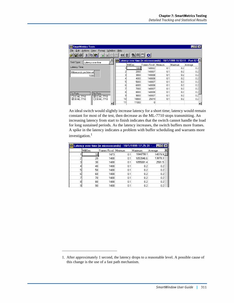
Chapter 7: SmartMetrics TestingDetailed Tracking and Statistical Results
An ideal switch would slightly increase latency for a short time; latency would remain constant for most of the test, then decrease as the ML-7710 stops transmitting. An increasing latency from start to finish indicates that the switch cannot handle the load for long sustained periods. As the latency increases, the switch buffers more frames. A spike in the latency indicates a problem with buffer scheduling and warrants more investigation.1
1. After approximately 1 second, the latency drops to a reasonable level. A possible cause of this change is the use of a fast path mechanism.
SmartWindow User Guide | 311
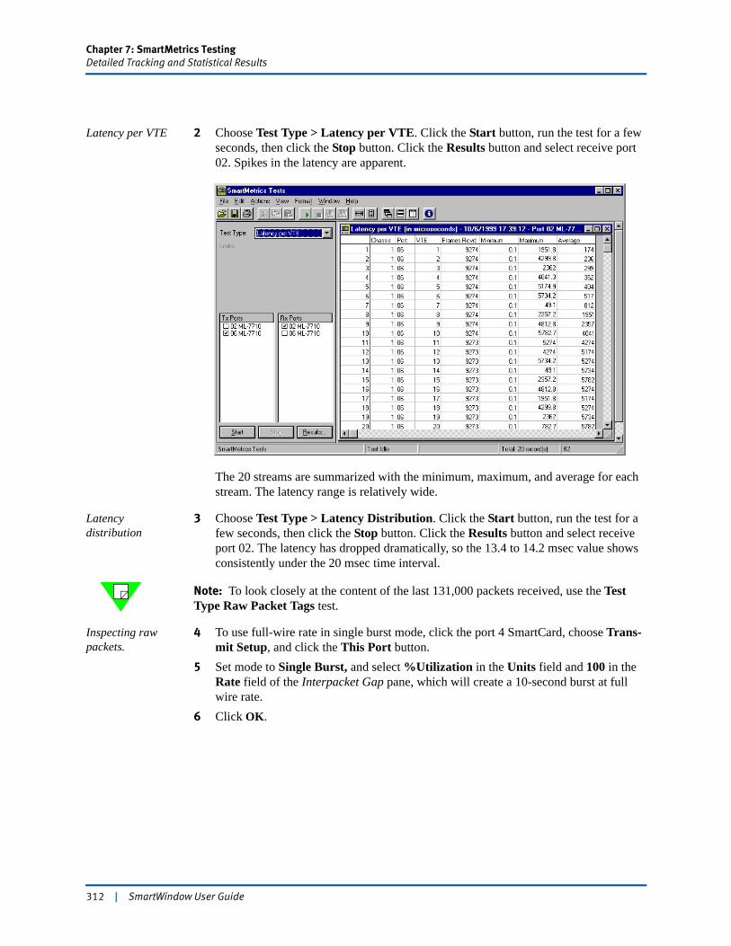
Chapter 7: SmartMetrics TestingDetailed Tracking and Statistical Results
Latency per VTE 2 Choose Test Type > Latency per VTE. Click the Start button, run the test for a few seconds, then click the Stop button. Click the Results button and select receive port 02. Spikes in the latency are apparent.
The 20 streams are summarized with the minimum, maximum, and average for each stream. The latency range is relatively wide.
Latency distribution
3 Choose Test Type > Latency Distribution. Click the Start button, run the test for a few seconds, then click the Stop button. Click the Results button and select receive port 02. The latency has dropped dramatically, so the 13.4 to 14.2 msec value shows consistently under the 20 msec time interval.
Note: To look closely at the content of the last 131,000 packets received, use the Test Type Raw Packet Tags test.
Inspecting raw packets.
4 To use full-wire rate in single burst mode, click the port 4 SmartCard, choose Trans-mit Setup, and click the This Port button.
5 Set mode to Single Burst, and select %Utilization in the Units field and 100 in the Rate field of the Interpacket Gap pane, which will create a 10-second burst at full wire rate.
6 Click OK.
312 | SmartWindow User Guide
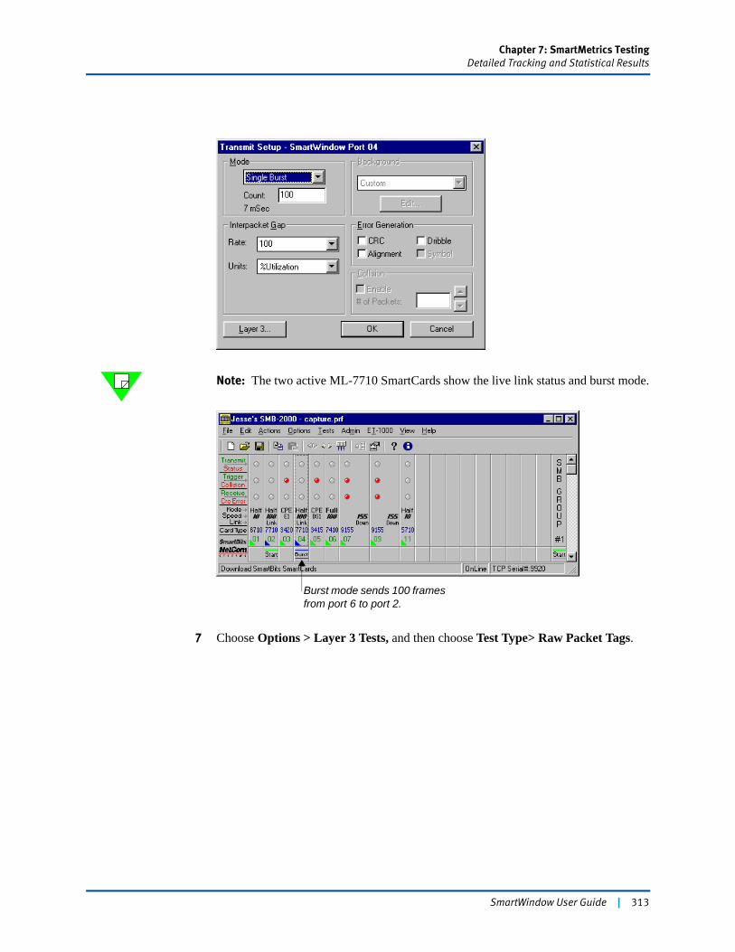
Chapter 7: SmartMetrics TestingDetailed Tracking and Statistical Results
Note: The two active ML-7710 SmartCards show the live link status and burst mode.
7 Choose Options > Layer 3 Tests, and then choose Test Type> Raw Packet Tags.
Burst mode sends 100 frames from port 6 to port 2.
SmartWindow User Guide | 313
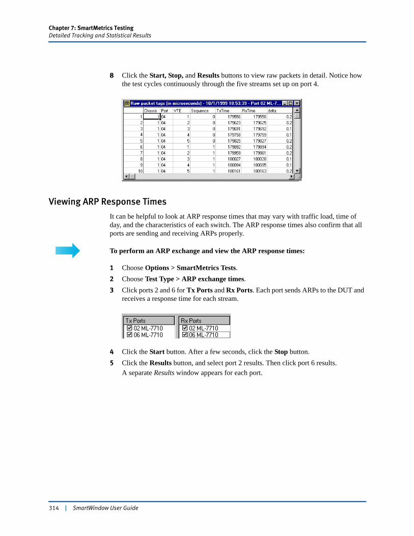
Chapter 7: SmartMetrics TestingDetailed Tracking and Statistical Results
8 Click the Start, Stop, and Results buttons to view raw packets in detail. Notice how the test cycles continuously through the five streams set up on port 4.
Viewing ARP Response Times
It can be helpful to look at ARP response times that may vary with traffic load, time of day, and the characteristics of each switch. The ARP response times also confirm that all ports are sending and receiving ARPs properly.
To perform an ARP exchange and view the ARP response times:
1 Choose Options > SmartMetrics Tests.2 Choose Test Type > ARP exchange times.3 Click ports 2 and 6 for Tx Ports and Rx Ports. Each port sends ARPs to the DUT and
receives a response time for each stream.
4 Click the Start button. After a few seconds, click the Stop button.5 Click the Results button, and select port 2 results. Then click port 6 results.
A separate Results window appears for each port.
314 | SmartWindow User Guide
Chapter 8
Testing Gigabit Routers
SmartBits Gigabit cards and modules plus SmartWindow provide the tools for effective testing and evaluation of Gigabit switches and routers, including the emerging 10 Gbps Ethernet devices.
See “Additional Feature for the LAN-3710AL/AE/AS” on page 445 for capabilities and options not covered by the setup examples.
In this chapter...
• Testing Gigabit Routers with SmartMetrics . . . . 316
• Tests Using the XLW-3721A/XFP-3731A TeraMetrics Modules . . . . 318
• XAUI Testing . . . . 342
• Test Using the LAN-3710AL/AE/AS 10GbE Module . . . . 355
• Test Using the LAN-3311A TeraMetrics Module . . . . 374
• Test Using the LAN-3201B/C SmartMetrics Module . . . . 380
• Configuring Transmit Streams on TeraMetrics Modules . . . . 392
• Configuring the DUT . . . . 413
• Configuring SmartCounters . . . . 415
• Running SmartCounters . . . . 435
• DiffServ Counters . . . . 437
• VLAN Priority Counters . . . . 440
• Additional Feature for the LAN-3710AL/AE/AS . . . . 445
SmartWindow User Guide | 315
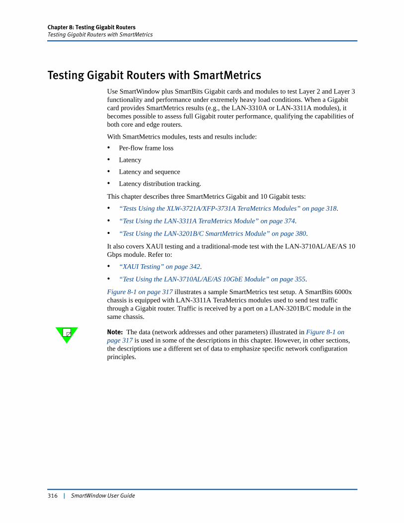
Chapter 8: Testing Gigabit RoutersTesting Gigabit Routers with SmartMetrics
Testing Gigabit Routers with SmartMetricsUse SmartWindow plus SmartBits Gigabit cards and modules to test Layer 2 and Layer 3 functionality and performance under extremely heavy load conditions. When a Gigabit card provides SmartMetrics results (e.g., the LAN-3310A or LAN-3311A modules), it becomes possible to assess full Gigabit router performance, qualifying the capabilities of both core and edge routers.
With SmartMetrics modules, tests and results include:• Per-flow frame loss
• Latency
• Latency and sequence
• Latency distribution tracking.
This chapter describes three SmartMetrics Gigabit and 10 Gigabit tests:
• “Tests Using the XLW-3721A/XFP-3731A TeraMetrics Modules” on page 318.
• “Test Using the LAN-3311A TeraMetrics Module” on page 374.
• “Test Using the LAN-3201B/C SmartMetrics Module” on page 380.
It also covers XAUI testing and a traditional-mode test with the LAN-3710AL/AE/AS 10 Gbps module. Refer to:
• “XAUI Testing” on page 342.
• “Test Using the LAN-3710AL/AE/AS 10GbE Module” on page 355.
Figure 8-1 on page 317 illustrates a sample SmartMetrics test setup. A SmartBits 6000x chassis is equipped with LAN-3311A TeraMetrics modules used to send test traffic through a Gigabit router. Traffic is received by a port on a LAN-3201B/C module in the same chassis.
Note: The data (network addresses and other parameters) illustrated in Figure 8-1 on page 317 is used in some of the descriptions in this chapter. However, in other sections, the descriptions use a different set of data to emphasize specific network configuration principles.
316 | SmartWindow User Guide
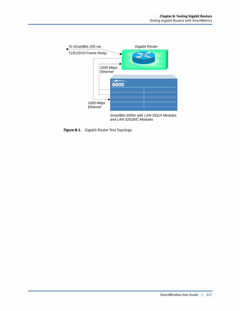
Chapter 8: Testing Gigabit RoutersTesting Gigabit Routers with SmartMetrics
Figure 8-1. Gigabit Router Test Topology
Gigabit Router
T1/E1/DS3 Frame Relay
1000 Mbps
SmartBits 6000x with LAN-3311A Modules
To SmartBits 200 via
1000 Mbps
Ethernet
Ethernet
and LAN-3201B/C Modules
SmartWindow User Guide | 317
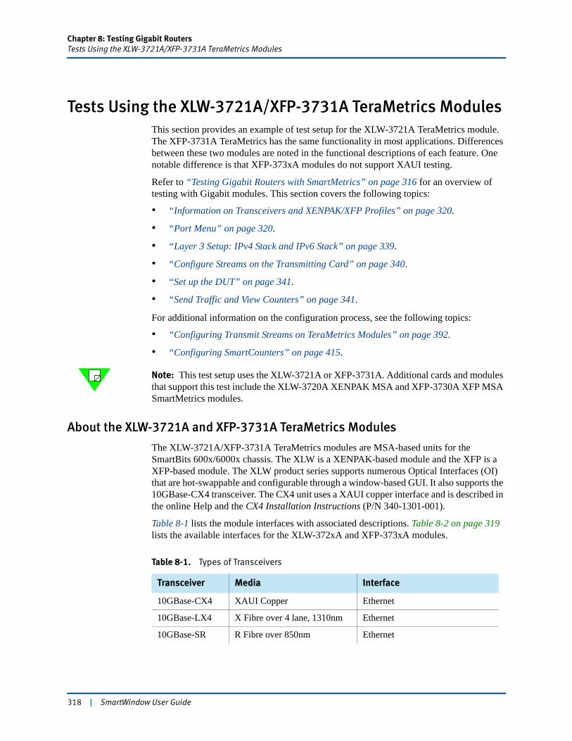
Chapter 8: Testing Gigabit RoutersTests Using the XLW-3721A/XFP-3731A TeraMetrics Modules
Tests Using the XLW-3721A/XFP-3731A TeraMetrics ModulesThis section provides an example of test setup for the XLW-3721A TeraMetrics module. The XFP-3731A TeraMetrics has the same functionality in most applications. Differences between these two modules are noted in the functional descriptions of each feature. One notable difference is that XFP-373xA modules do not support XAUI testing.
Refer to “Testing Gigabit Routers with SmartMetrics” on page 316 for an overview of testing with Gigabit modules. This section covers the following topics:
• “Information on Transceivers and XENPAK/XFP Profiles” on page 320.
• “Port Menu” on page 320.
• “Layer 3 Setup: IPv4 Stack and IPv6 Stack” on page 339.
• “Configure Streams on the Transmitting Card” on page 340.
• “Set up the DUT” on page 341.
• “Send Traffic and View Counters” on page 341.
For additional information on the configuration process, see the following topics:
• “Configuring Transmit Streams on TeraMetrics Modules” on page 392.
• “Configuring SmartCounters” on page 415.
Note: This test setup uses the XLW-3721A or XFP-3731A. Additional cards and modules that support this test include the XLW-3720A XENPAK MSA and XFP-3730A XFP MSA SmartMetrics modules.
About the XLW-3721A and XFP-3731A TeraMetrics Modules
The XLW-3721A/XFP-3731A TeraMetrics modules are MSA-based units for the SmartBits 600x/6000x chassis. The XLW is a XENPAK-based module and the XFP is a XFP-based module. The XLW product series supports numerous Optical Interfaces (OI) that are hot-swappable and configurable through a window-based GUI. It also supports the 10GBase-CX4 transceiver. The CX4 unit uses a XAUI copper interface and is described in the online Help and the CX4 Installation Instructions (P/N 340-1301-001).
Table 8-1 lists the module interfaces with associated descriptions. Table 8-2 on page 319 lists the available interfaces for the XLW-372xA and XFP-373xA modules.
Table 8-1. Types of Transceivers
Transceiver Media Interface
10GBase-CX4 XAUI Copper Ethernet
10GBase-LX4 X Fibre over 4 lane, 1310nm Ethernet
10GBase-SR R Fibre over 850nm Ethernet
318 | SmartWindow User Guide
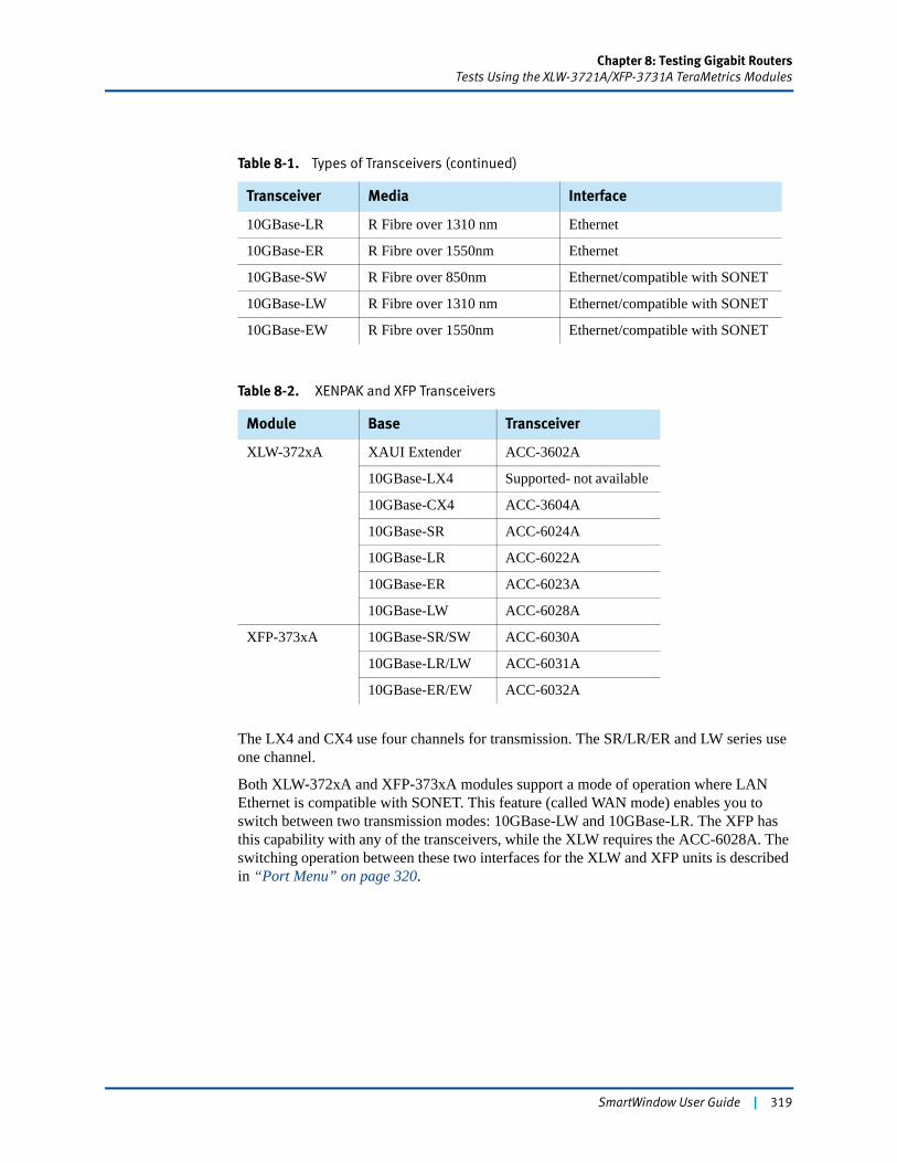
Chapter 8: Testing Gigabit RoutersTests Using the XLW-3721A/XFP-3731A TeraMetrics Modules
The LX4 and CX4 use four channels for transmission. The SR/LR/ER and LW series use one channel.
Both XLW-372xA and XFP-373xA modules support a mode of operation where LAN Ethernet is compatible with SONET. This feature (called WAN mode) enables you to switch between two transmission modes: 10GBase-LW and 10GBase-LR. The XFP has this capability with any of the transceivers, while the XLW requires the ACC-6028A. The switching operation between these two interfaces for the XLW and XFP units is described in “Port Menu” on page 320.
10GBase-LR R Fibre over 1310 nm Ethernet
10GBase-ER R Fibre over 1550nm Ethernet
10GBase-SW R Fibre over 850nm Ethernet/compatible with SONET
10GBase-LW R Fibre over 1310 nm Ethernet/compatible with SONET
10GBase-EW R Fibre over 1550nm Ethernet/compatible with SONET
Table 8-2. XENPAK and XFP Transceivers
Module Base Transceiver
XLW-372xA XAUI Extender ACC-3602A
10GBase-LX4 Supported- not available
10GBase-CX4 ACC-3604A
10GBase-SR ACC-6024A
10GBase-LR ACC-6022A
10GBase-ER ACC-6023A
10GBase-LW ACC-6028A
XFP-373xA 10GBase-SR/SW ACC-6030A
10GBase-LR/LW ACC-6031A
10GBase-ER/EW ACC-6032A
Table 8-1. Types of Transceivers (continued)
Transceiver Media Interface
SmartWindow User Guide | 319
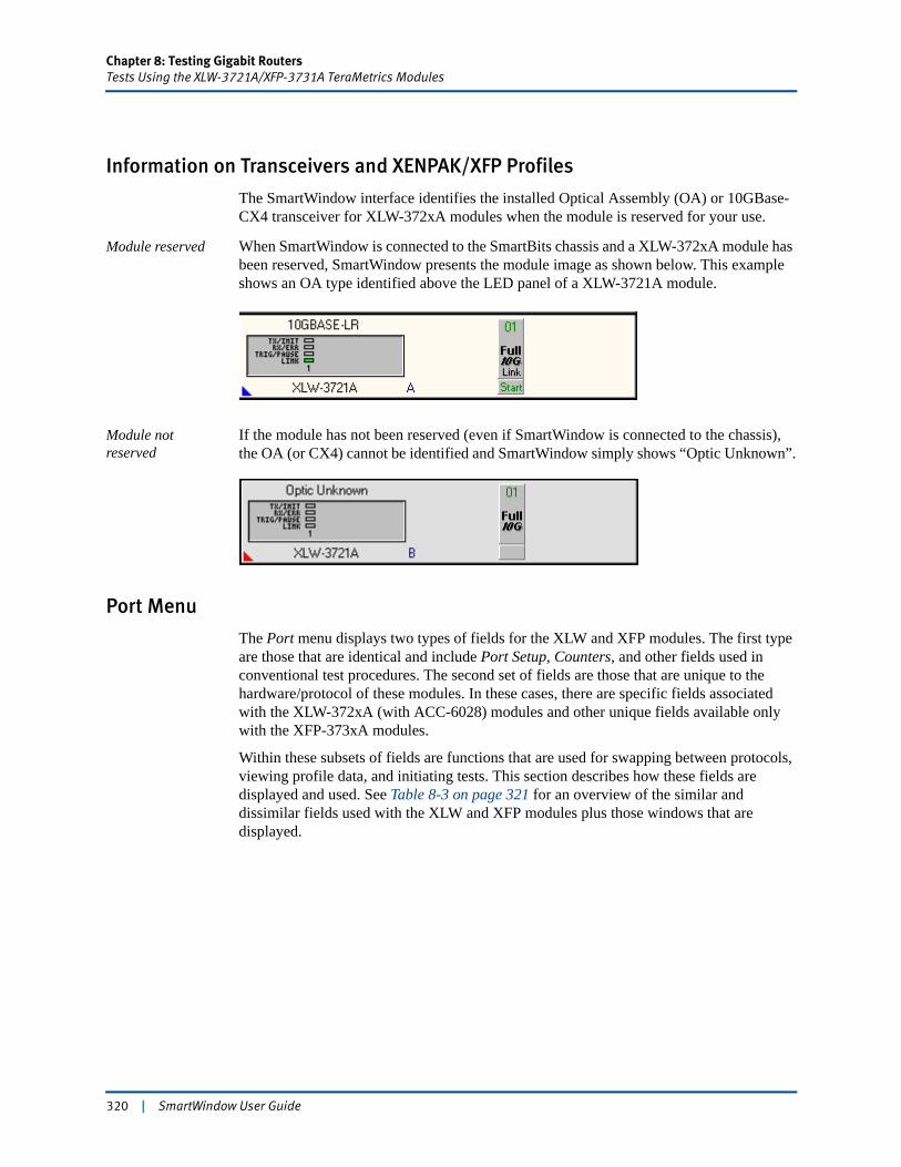
Chapter 8: Testing Gigabit RoutersTests Using the XLW-3721A/XFP-3731A TeraMetrics Modules
Information on Transceivers and XENPAK/XFP Profiles
The SmartWindow interface identifies the installed Optical Assembly (OA) or 10GBase-CX4 transceiver for XLW-372xA modules when the module is reserved for your use.
Module reserved When SmartWindow is connected to the SmartBits chassis and a XLW-372xA module has been reserved, SmartWindow presents the module image as shown below. This example shows an OA type identified above the LED panel of a XLW-3721A module.
Module not reserved
If the module has not been reserved (even if SmartWindow is connected to the chassis), the OA (or CX4) cannot be identified and SmartWindow simply shows “Optic Unknown”.
Port Menu
The Port menu displays two types of fields for the XLW and XFP modules. The first type are those that are identical and include Port Setup, Counters, and other fields used in conventional test procedures. The second set of fields are those that are unique to the hardware/protocol of these modules. In these cases, there are specific fields associated with the XLW-372xA (with ACC-6028) modules and other unique fields available only with the XFP-373xA modules.
Within these subsets of fields are functions that are used for swapping between protocols, viewing profile data, and initiating tests. This section describes how these fields are displayed and used. See Table 8-3 on page 321 for an overview of the similar and dissimilar fields used with the XLW and XFP modules plus those windows that are displayed.
320 | SmartWindow User Guide
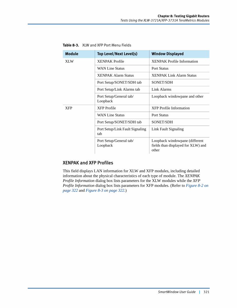
Chapter 8: Testing Gigabit RoutersTests Using the XLW-3721A/XFP-3731A TeraMetrics Modules
XENPAK and XFP Profiles
This field displays LAN information for XLW and XFP modules, including detailed information about the physical characteristics of each type of module. The XENPAK Profile Information dialog box lists parameters for the XLW modules while the XFP Profile Information dialog box lists parameters for XFP modules. (Refer to Figure 8-2 on page 322 and Figure 8-3 on page 322.)
Table 8-3. XLW and XFP Port Menu Fields
Module Top Level/Next Level(s) Window Displayed
XLW XENPAK Profile XENPAK Profile Information
WAN Line Status Port Status
XENPAK Alarm Status XENPAK Link Alarm Status
Port Setup/SONET/SDH tab SONET/SDH
Port Setup/Link Alarms tab Link Alarms
Port Setup/General tab/Loopback
Loopback windowpane and other
XFP XFP Profile XFP Profile Information
WAN Line Status Port Status
Port Setup/SONET/SDH tab SONET/SDH
Port Setup/Link Fault Signaling tab
Link Fault Signaling
Port Setup/General tab/Loopback
Loopback windowpane (different fields than displayed for XLW) and other
SmartWindow User Guide | 321
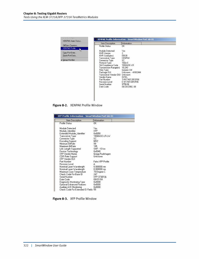
Chapter 8: Testing Gigabit RoutersTests Using the XLW-3721A/XFP-3731A TeraMetrics Modules
Figure 8-2. XENPAK Profile Window
Figure 8-3. XFP Profile Window
322 | SmartWindow User Guide
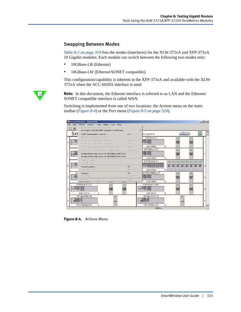
Chapter 8: Testing Gigabit RoutersTests Using the XLW-3721A/XFP-3731A TeraMetrics Modules
Swapping Between Modes
Table 8-2 on page 319 lists the modes (interfaces) for the XLW-372xA and XFP-373xA 10 Gigabit modules. Each module can switch between the following two modes only:
• 10GBase-LR (Ethernet)
• 10GBase-LW (Ethernet/SONET compatible).
This configuration/capability is inherent in the XFP-373xA and available with the XLW-372xA when the ACC-6028A interface is used.
Note: In this document, the Ethernet interface is referred to as LAN and the Ethernet/SONET compatible interface is called WAN.
Switching is implemented from one of two locations: the Actions menu on the main toolbar (Figure 8-4) or the Port menu (Figure 8-5 on page 324).
Figure 8-4. Actions Menu
SmartWindow User Guide | 323
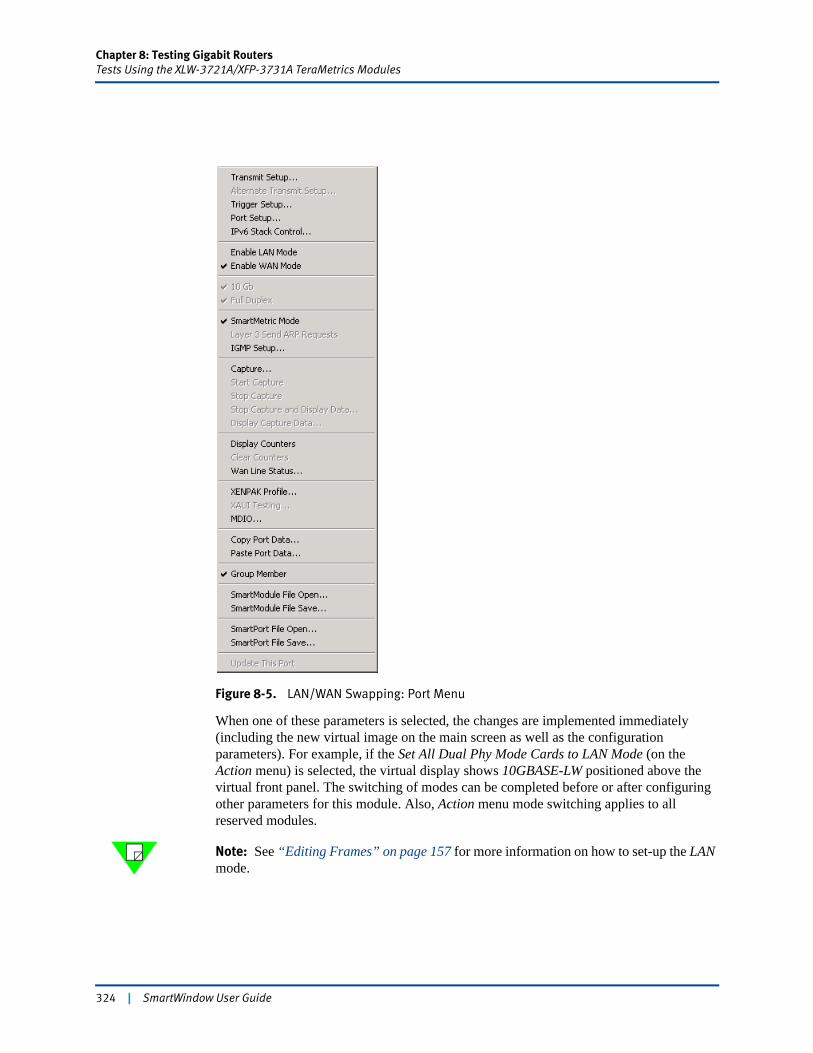
Chapter 8: Testing Gigabit RoutersTests Using the XLW-3721A/XFP-3731A TeraMetrics Modules
Figure 8-5. LAN/WAN Swapping: Port Menu
When one of these parameters is selected, the changes are implemented immediately (including the new virtual image on the main screen as well as the configuration parameters). For example, if the Set All Dual Phy Mode Cards to LAN Mode (on the Action menu) is selected, the virtual display shows 10GBASE-LW positioned above the virtual front panel. The switching of modes can be completed before or after configuring other parameters for this module. Also, Action menu mode switching applies to all reserved modules.
Note: See “Editing Frames” on page 157 for more information on how to set-up the LAN mode.
324 | SmartWindow User Guide
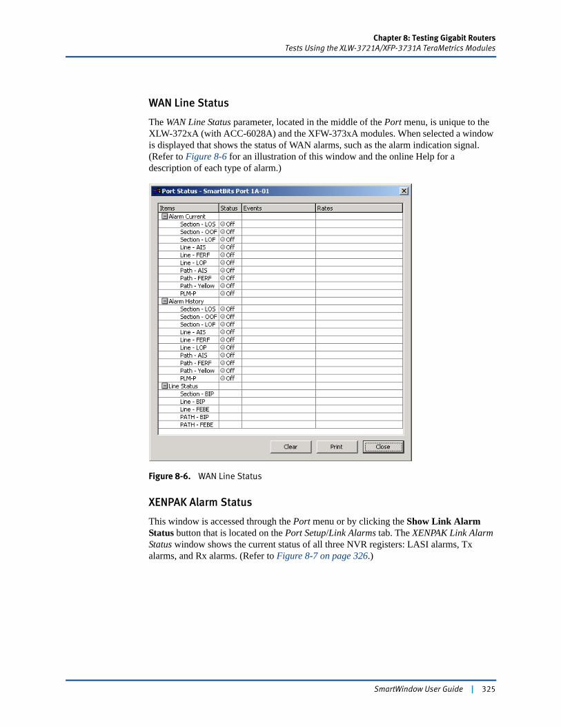
Chapter 8: Testing Gigabit RoutersTests Using the XLW-3721A/XFP-3731A TeraMetrics Modules
WAN Line Status
The WAN Line Status parameter, located in the middle of the Port menu, is unique to the XLW-372xA (with ACC-6028A) and the XFW-373xA modules. When selected a window is displayed that shows the status of WAN alarms, such as the alarm indication signal. (Refer to Figure 8-6 for an illustration of this window and the online Help for a description of each type of alarm.)
Figure 8-6. WAN Line Status
XENPAK Alarm Status
This window is accessed through the Port menu or by clicking the Show Link Alarm Status button that is located on the Port Setup/Link Alarms tab. The XENPAK Link Alarm Status window shows the current status of all three NVR registers: LASI alarms, Tx alarms, and Rx alarms. (Refer to Figure 8-7 on page 326.)
SmartWindow User Guide | 325
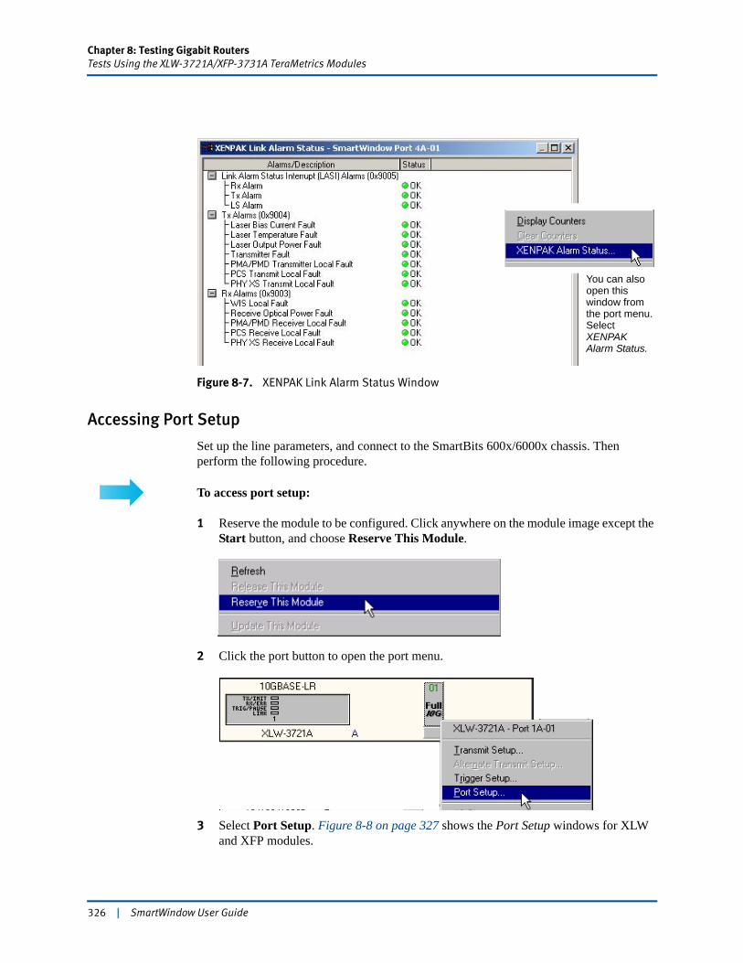
Chapter 8: Testing Gigabit RoutersTests Using the XLW-3721A/XFP-3731A TeraMetrics Modules
Figure 8-7. XENPAK Link Alarm Status Window
Accessing Port Setup
Set up the line parameters, and connect to the SmartBits 600x/6000x chassis. Then perform the following procedure.
To access port setup:
1 Reserve the module to be configured. Click anywhere on the module image except the Start button, and choose Reserve This Module.
2 Click the port button to open the port menu.
3 Select Port Setup. Figure 8-8 on page 327 shows the Port Setup windows for XLW and XFP modules.
You can also open this window from the port menu. Select XENPAK Alarm Status.
326 | SmartWindow User Guide
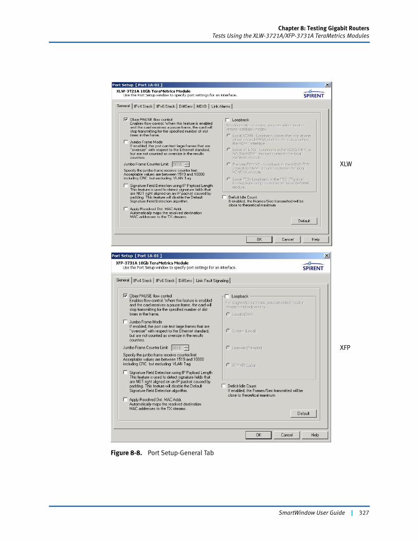
Chapter 8: Testing Gigabit RoutersTests Using the XLW-3721A/XFP-3731A TeraMetrics Modules
Figure 8-8. Port Setup-General Tab
XLW
XFP
SmartWindow User Guide | 327
Chapter 8: Testing Gigabit RoutersTests Using the XLW-3721A/XFP-3731A TeraMetrics Modules
Notes: • The number and type of tabs are different for each module.
• The loopback functions are different for each module. These are described in the “General Tab”section.
• The number of Port Setup tabs for the LAN mode is different than the number of tabs for the WAN mode. (See Table 8-4.)
General Tab
These options include flow control, jumbo frames, and internal loopback. Click the Default button to reset all options to default values.
• Obey Pause Flow Control: Permits the port to respond to pause frames received from the DUT. (This option is enabled by default.)
• Jumbo Frame Mode: Allows the port to test large frames, with respect to the Ethernet definition of frames. These frames are called “oversize.” When this checkbox is selected, the port can send and receive jumbo frames. (See “Jumbo Frames” on page 184 in Chapter 5, “Advanced Operational Theory” for a detailed explanation.)
• Signature Field Detection using IP Payload Length (without FCS): Refer to Table 7-1 on page 240 for a description of this field.
• Apply Resolved Dst MAC Address: Refer to Table 7-1 on page 240 for a description of this field.
• Loopback: Refer to “Loopback” on page 329 for an explanation of how to use the loopback function.
Table 8-4. Port Setup Tabs for LAN and WAN Modes
Tabs LAN mode WAN mode
General Yes Yes
SONET/SDH No Yes
IPv4 Stack Yes Yes
IPv6 Stack Yes Yes
DiffServ Yes Yes
MDIO Yes Yes
328 | SmartWindow User Guide
Chapter 8: Testing Gigabit RoutersTests Using the XLW-3721A/XFP-3731A TeraMetrics Modules
• Deficit Idle Count: This checkbox enables the use of deficit idle count to more closely match the requested throughput to the actual transmitted throughput. The difference between the requested and actual throughput is maximized when you want to transmit a large number of small frames that do not end exactly on a 4-byte boundary. In these cases, using deficit idle count can help close or eliminate the difference. (Refer to the 802.3ae document section 46.3.1.4 titled “Start control character alignment” for the technical details about how deficit idle count facilitates a closer match between desired throughput and the actual transmitted throughput. Refer to “Defining the Schedule Mode” on page 393 for more information on how and when IFG is used.)
Loopback
The loopback tests vary between the XLW-372xA and XFP-373xA modules. The XLW-372xA module tests use the XAUI interface while the XFP-373xA modules use the PMA and PMS interfaces.
XLW-372xA Loopback
The XLW-372xA modules have internal loopback modes at one of four points in the XENPAK/XAUI interface. (Refer to Figure 8-9 on page 330.)
• Local XGMII – Loopback closes the loop at one of the internal FPGAs in the XLW-372xA module before data reaches the XGMII interface.
• Local DTE XS – Loopback in the XGXS DTE, an XGMII-to-XAUI interface chip located in the XLW-372xA module.
• Remote PHY XS – Loopback in the XGXS PHY, a XAUI-to-XGMII device located in the XENPAK optical module assembly.
• Local PCS – Loopback in the Physical Coding Sublayer (PCS), located in the XENPAK optical module assembly.
SmartWindow User Guide | 329
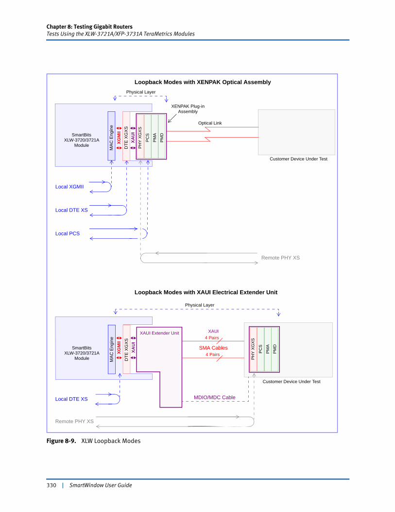
Chapter 8: Testing Gigabit RoutersTests Using the XLW-3721A/XFP-3731A TeraMetrics Modules
Figure 8-9. XLW Loopback Modes
PH
Y X
GX
S
PC
S
PM
A
PM
DCustomer Device Under Test
DTE
XG
XSXA
UI
Local XGMII
Remote PHY XS
SmartBitsXLW-3720/3721A
Local DTE XS
Local PCS
MA
C E
ngin
eXENPAK Plug-in
Assembly
Physical Layer
XGM
II
Module
Customer Device Under Test
DTE
XG
XS
Remote PHY XS
SmartBitsXLW-3720/3721A
Local DTE XS
MA
C E
ngin
e 4 Pairs
4 Pairs
Physical Layer
XAUI Extender Unit
PH
Y X
GX
S
PC
S
PM
A
PM
D
MDIO/MDC Cable
Module
Loopback Modes with XENPAK Optical Assembly
Loopback Modes with XAUI Electrical Extender Unit
SMA Cables
XAU
I
XGM
IIOptical Link
XAUI
330 | SmartWindow User Guide
Chapter 8: Testing Gigabit RoutersTests Using the XLW-3721A/XFP-3731A TeraMetrics Modules
XFP-373xA Loopback
The XFP-373xA modules have four loopback modes:
• Local XGMII
• System (Local)
• Lineside (Remote)
• XFP XFI Local.
A brief description of these modes is given in Table 8-5. (Refer to Figure 8-10 on page 332 for an illustration of these loopback modes.)
Table 8-5. XFP Loopbacks
Name Description
Local XGMII Packets loopback locally from PCS.
System (Local) Packets loopback locally from PMA.
Lineside (Remote) Packets loopback remotely from PMA.
XFP XFI Local Packets loopback locally from PMD.
SmartWindow User Guide | 331
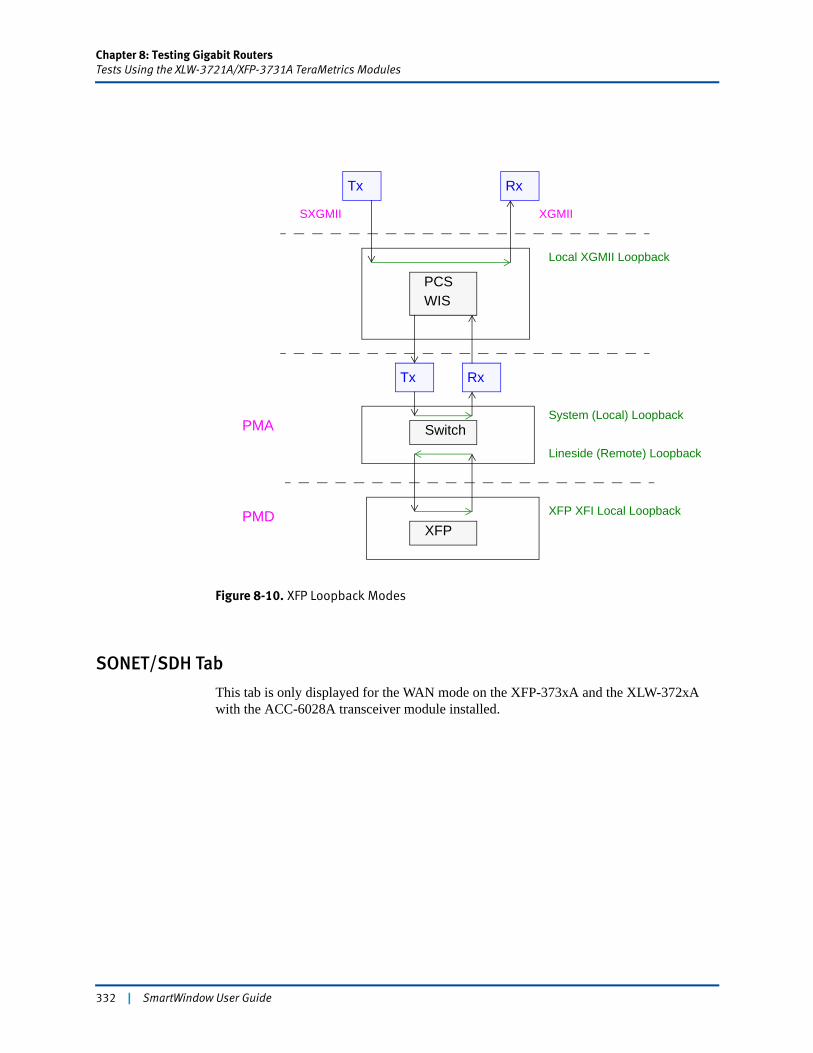
Chapter 8: Testing Gigabit RoutersTests Using the XLW-3721A/XFP-3731A TeraMetrics Modules
Figure 8-10. XFP Loopback Modes
SONET/SDH Tab
This tab is only displayed for the WAN mode on the XFP-373xA and the XLW-372xA with the ACC-6028A transceiver module installed.
Tx
Local XGMII Loopback
Rx
PCSWIS
SXGMII XGMII
RxTx
PMA
PMD
System (Local) Loopback
Lineside (Remote) Loopback
XFP XFI Local Loopback
XFP
Switch
332 | SmartWindow User Guide
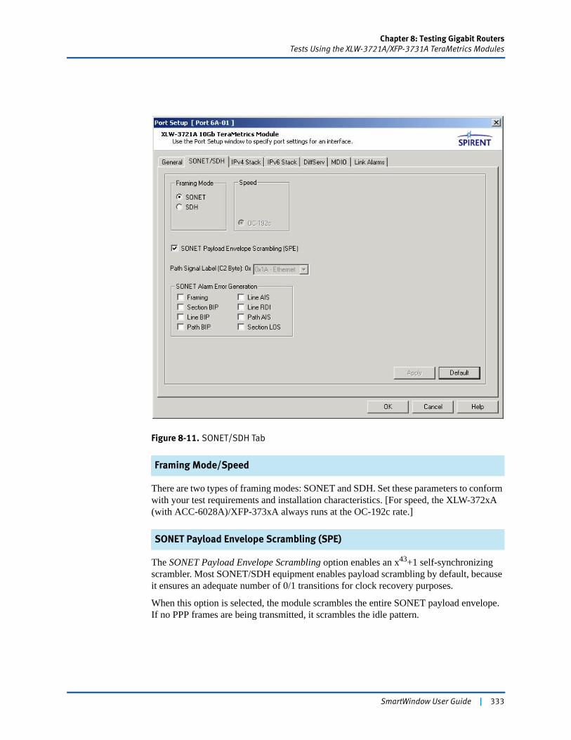
Chapter 8: Testing Gigabit RoutersTests Using the XLW-3721A/XFP-3731A TeraMetrics Modules
Figure 8-11. SONET/SDH Tab
Framing Mode/Speed
There are two types of framing modes: SONET and SDH. Set these parameters to conform with your test requirements and installation characteristics. [For speed, the XLW-372xA (with ACC-6028A)/XFP-373xA always runs at the OC-192c rate.]
SONET Payload Envelope Scrambling (SPE)
The SONET Payload Envelope Scrambling option enables an x43+1 self-synchronizing scrambler. Most SONET/SDH equipment enables payload scrambling by default, because it ensures an adequate number of 0/1 transitions for clock recovery purposes.
When this option is selected, the module scrambles the entire SONET payload envelope. If no PPP frames are being transmitted, it scrambles the idle pattern.
SmartWindow User Guide | 333
Chapter 8: Testing Gigabit RoutersTests Using the XLW-3721A/XFP-3731A TeraMetrics Modules
Path Signal Label (C2 Byte) 0x
The Path Signal Label C2 Byte identifies the contents of the SONET/SDH Synchronous Payload Envelope (SPE). The default value 0x1A (decimal 36) indicates Ethernet and should be used for SONET/SDH tests.
SONET Alarm Error Generation
Optionally, SONET alarm error generation can be enabled. Select the appropriate checkboxes in order to choose which errors should be generated by the card. (Refer to the online Help for a complete description of each alarm.)
Apply Function
At the bottom of the SONET/SDH tab is the Apply button. Press this button to generate a SONET alarm without closing this window. This feature gives you the capability to send alarms repeatedly without re-configuring the alarm parameters or having to re-open this window. (In contrast, click the OK button to send the alarm and close the window.)
This button is disabled when the chassis is offline.
IPv4 Stack and IPv6 Stack Tabs
These tabs on the Port Setup window configure the local IP stack. Set values on these tabs for the following purposes:
• To set the gateway IP address of the router port (DUT). (This operation is required for Layer 3 switches.)
• To change MAC and IP addresses so that they do not duplicate stream addresses.
• To set the netmask for management frames. (Optional; this operation is ignored by streams.)
• To specify a ping IP address for pings and SNMP frames if needed (optional), as well as the frequency of ping, SNMP, or RIP packets. (Optional)
• To enable virtual flow cyclic ARPs. (See “Virtual Flow Cyclic ARPs and ARP Requests” on page 186 in Chapter 5, “Advanced Operational Theory” for further information.)
• To enable gratuitous ARP mode. (See “Gratuitous ARP Mode” on page 196 in Chapter 5, “Advanced Operational Theory” for further information.)
Refer to “Layer 3 Setup: IPv4 Stack and IPv6 Stack” on page 339 for the steps to select values for the fields and options on these tabs.
334 | SmartWindow User Guide
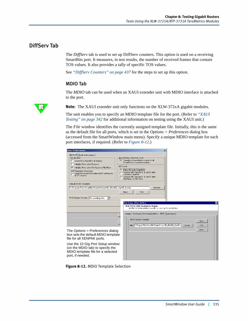
Chapter 8: Testing Gigabit RoutersTests Using the XLW-3721A/XFP-3731A TeraMetrics Modules
DiffServ Tab
The DiffServ tab is used to set up DiffServ counters. This option is used on a receiving SmartBits port. It measures, in test results, the number of received frames that contain TOS values. It also provides a tally of specific TOS values.
See “DiffServ Counters” on page 437 for the steps to set up this option.
MDIO Tab
The MDIO tab can be used when an XAUI extender unit with MDIO interface is attached to the port.
Note: The XAUI extender unit only functions on the XLW-372xA gigabit modules.
The unit enables you to specify an MDIO template file for the port. (Refer to “XAUI Testing” on page 342 for additional information on testing using the XAUI unit.)
The File window identifies the currently assigned template file. Initially, this is the same as the default file for all ports, which is set in the Options > Preferences dialog box (accessed from the SmartWindow main menu). Specify a unique MDIO template for each port interfaces, if required. (Refer to Figure 8-12.)
Figure 8-12. MDIO Template Selection
The Options > Preferences dialog box sets the default MDIO template file for all XENPAK ports.Use the 10 Gig Port Setup window (on the MDIO tab) to specify the MDIO template file for a selected port, if needed.
SmartWindow User Guide | 335
Chapter 8: Testing Gigabit RoutersTests Using the XLW-3721A/XFP-3731A TeraMetrics Modules
Predefined template files
SmartWindow includes predefined MDIO template files that are located in the installation directory. (Click Browse to open the folder and view the files.) The following is a list of these files:
• ieee802_3ae45.midoBased on IEEE Std.802.3ae, with the first five devices defined. No vendor specifics; no extensions.
• jdsu802_3ae45.mdioJDSU IEEE Std.802.3ae. Includes the vendor’s specifics and extensions.
• BitBlitz802_3ae45.mdioBitBlitz IEEE Std.802.3ae. Includes the vendor’s specifics and extensions.
• agilent802_3ae45.mdioAgilent IEEE Std.802.3ae. Includes the vendor’s specifics and extensions.
• intel802_3ae45.mdioIntel’s IEEE Std.802.3ae. Includes the vendor’s specifics and extensions.
Creating a new file or editing a defined file.
Other options on the MDIO tab enable you to edit a selected template file or create a completely new file. In these cases, use the MDIO Template Editor to set the desired values for devices and registers.
An MDIO Status window provides detailed information on MDIO settings for the port.
Link Alarms Tab
The Link Alarms tab displays configuration parameters (i.e., bit values for non-volatile registers) for the LAN mode. It also has a link to the XENPAK Link Alarm Status window. (This tab is only displayed on the XLW modules.)
• Link Alarm Status Interrupt (LASI) Control Register (0x9002)This is a LASI control register that allows global masking of the RX_ALARM, TX_ALARM, and LS_ALARM inputs. Select the appropriate checkboxes to enable individual alarms.
• Tx Alarm Control Register (0x9001)The Tx alarm control register can be programmed to assert when specific transmit path fault condition(s) are present, based on the indications of the Tx alarm status reg-ister (0x9004). (The contents of the Tx alarm control register are ANDed with the contents of the Tx alarm status register before applying an OR function that generates the TX_ALARM signal.) Select the appropriate checkboxes to enable individual faults.
• Rx Alarm Control Register (0x9000)The Rx alarm control register can be programmed to assert when specific receive path fault condition(s) are present, based on the indications of the Rx alarm status register (0x9003). (The contents of the Rx alarm control register are ANDed with the contents of the Rx alarm status register before applying an OR function that generates the RX_ALARM signal.) Select the appropriate checkboxes to enable individual faults.
336 | SmartWindow User Guide
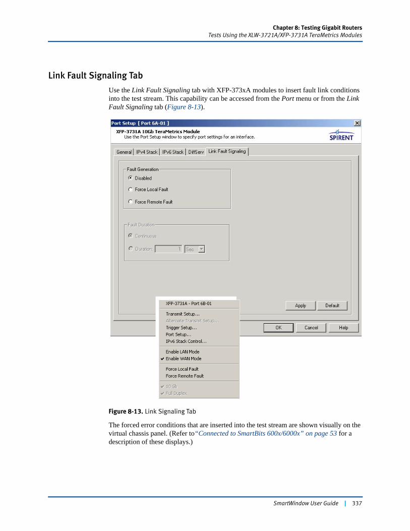
Chapter 8: Testing Gigabit RoutersTests Using the XLW-3721A/XFP-3731A TeraMetrics Modules
Link Fault Signaling Tab
Use the Link Fault Signaling tab with XFP-373xA modules to insert fault link conditions into the test stream. This capability can be accessed from the Port menu or from the Link Fault Signaling tab (Figure 8-13).
Figure 8-13. Link Signaling Tab
The forced error conditions that are inserted into the test stream are shown visually on the virtual chassis panel. (Refer to“Connected to SmartBits 600x/6000x” on page 53 for a description of these displays.)
SmartWindow User Guide | 337
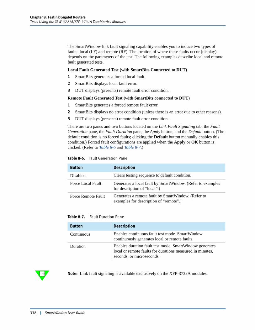
Chapter 8: Testing Gigabit RoutersTests Using the XLW-3721A/XFP-3731A TeraMetrics Modules
The SmartWindow link fault signaling capability enables you to induce two types of faults: local (LF) and remote (RF). The location of where these faults occur (display) depends on the parameters of the test. The following examples describe local and remote fault generated tests.
Local Fault Generated Test (with SmartBits Connected to DUT)1 SmartBits generates a forced local fault.2 SmartBits displays local fault error.3 DUT displays (presents) remote fault error condition.
Remote Fault Generated Test (with SmartBits connected to DUT)1 SmartBits generates a forced remote fault error.2 SmartBits displays no error condition (unless there is an error due to other reasons).3 DUT displays (presents) remote fault error condition.
There are two panes and two buttons located on the Link Fault Signaling tab: the Fault Generation pane, the Fault Duration pane, the Apply button, and the Default button. (The default condition is no forced faults; clicking the Default button manually enables this condition.) Forced fault configurations are applied when the Apply or OK button is clicked. (Refer to Table 8-6 and Table 8-7.)
Note: Link fault signaling is available exclusively on the XFP-373xA modules.
Table 8-6. Fault Generation Pane
Button Description
Disabled Clears testing sequence to default condition.
Force Local Fault Generates a local fault by SmartWindow. (Refer to examples for description of “local”.)
Force Remote Fault Generates a remote fault by SmartWindow. (Refer to examples for description of “remote”.)
Table 8-7. Fault Duration Pane
Button Description
Continuous Enables continuous fault test mode. SmartWindow continuously generates local or remote faults.
Duration Enables duration fault test mode. SmartWindow generates local or remote faults for durations measured in minutes, seconds, or microseconds.
338 | SmartWindow User Guide
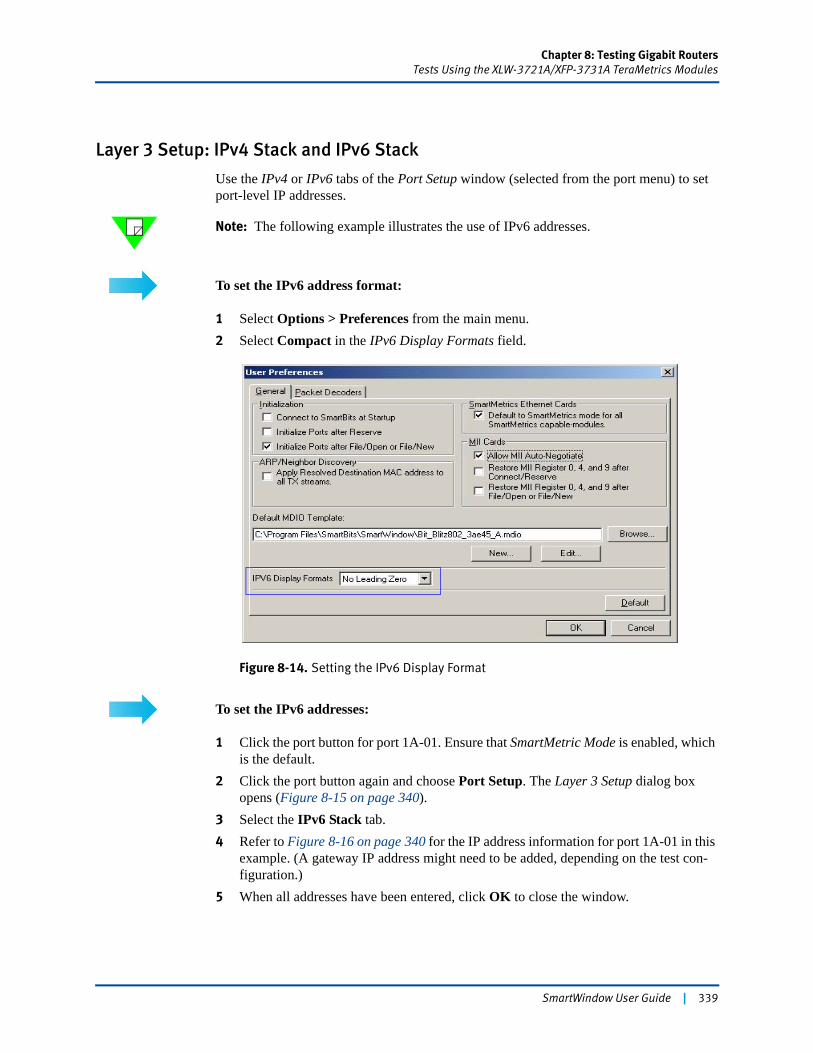
Chapter 8: Testing Gigabit RoutersTests Using the XLW-3721A/XFP-3731A TeraMetrics Modules
Layer 3 Setup: IPv4 Stack and IPv6 Stack
Use the IPv4 or IPv6 tabs of the Port Setup window (selected from the port menu) to set port-level IP addresses.
Note: The following example illustrates the use of IPv6 addresses.
To set the IPv6 address format:
1 Select Options > Preferences from the main menu.2 Select Compact in the IPv6 Display Formats field.
Figure 8-14. Setting the IPv6 Display Format
To set the IPv6 addresses:
1 Click the port button for port 1A-01. Ensure that SmartMetric Mode is enabled, which is the default.
2 Click the port button again and choose Port Setup. The Layer 3 Setup dialog box opens (Figure 8-15 on page 340).
3 Select the IPv6 Stack tab.4 Refer to Figure 8-16 on page 340 for the IP address information for port 1A-01 in this
example. (A gateway IP address might need to be added, depending on the test con-figuration.)
5 When all addresses have been entered, click OK to close the window.
SmartWindow User Guide | 339
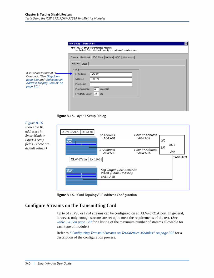
Chapter 8: Testing Gigabit RoutersTests Using the XLW-3721A/XFP-3731A TeraMetrics Modules
Figure 8-15. Layer 3 Setup Dialog
Figure 8-16 shows the IP addresses in SmartWindow Layer 3 setup fields. (These are default values.)
Figure 8-16. “Card Topology” IP Address Configuration
Configure Streams on the Transmitting Card
Up to 512 IPv6 or IPv4 streams can be configured on an XLW-3721A port. In general, however, only enough streams are set up to meet the requirements of the test. (See Table 5-13 on page 170 for a listing of the maximum number of streams allowable for each type of module.)
Refer to “Configuring Transmit Streams on TeraMetrics Modules” on page 392 for a description of the configuration process.
IPv6 address format is Compact. (See Step 2 on page 339 and “Selecting an Address Display Format” on page 171.)
DUT
IP Address
Peer IP Address
Ping Target: LAN-3101A/B
::A64:A01
::A64:A0A
2B-01 (Same Chassis)
IP Address192.0.0.2
Peer IP Address::A64:A02
0/0
1/02/0
::A64:A03
Tx 1A-01XLW-3721A
Rx 1B-01XLW-3721A
IP Address192.0.0.2
IP Address::A64:A09
::A64:A19
340 | SmartWindow User Guide

Chapter 8: Testing Gigabit RoutersTests Using the XLW-3721A/XFP-3731A TeraMetrics Modules
Set up the DUT
Refer to “Configuring the DUT” on page 413 for a description of how to set up the DUT.
Send Traffic and View Counters
Now you can transmit traffic and view counters. Proceed to “Running SmartCounters” on page 435 for the necessary steps.
SmartWindow User Guide | 341

Chapter 8: Testing Gigabit RoutersXAUI Testing
XAUI TestingThis section describes how to use the XAUI Testing option in SmartWindow, that is accessed from the XLW-3720A/3721A port menu. This section includes the following topics:
• “Overview of XAUI and MDIO”
• “SmartBits XAUI Extender Unit” on page 345
• “Typical XAUI Test Bench” on page 346
• “Setting up and Running XAUI Tests” on page 347.
Overview of XAUI and MDIO
Note: Refer to IEEE Draft P802.3ae for complete information on the topics outlined in this section. The following paragraphs introduce key concepts but are not meant to be a comprehensive presentation of all related details.
The 10 Gigabit Attachment Unit Interface (XAUI) is a standard developed by the IEEE 802.3ae 10 Gigabit Ethernet Task Force. Technical details are presented in clauses 47 and 48 of the IEEE 802.3ae 10Gb Ethernet standard. Also important are clauses 22 and 45, which define the Management Data Input/Output Interface (MDIO). The MDIO is similar in concept to the MII for Gigabit interfaces, but it provides important extensions in the number of devices and registers for configuration, status, and control.
Relationship to the OSI Model and Physical Layer
Figure 8-17 on page 343 illustrates the role of XAUI in the Ethernet physical layer, with reference to the OSI model and the 10 Gigabit Media Independent Interface (XGMII).
Between the MAC and PHY layers, the XGMII provides full-duplex operation at 10Gbps. Each direction is independent and contains a 32-bit data path plus clock and control signals. In total the interface is 74 bits wide.
XGMII provides “a simple, inexpensive, and easy-to-implement interconnection between the Media Access Control (MAC) sublayer and the Physical layer (PHY).”1 However, the operational bus length for XGMII is very short—7 centimeters—owing to the separate transmission of clock and data and timing requirements. As a result, the number of ports possible on a system line card is constrained by design factors.
1. Citations are from IEEE 802.3ae, Clause 46.1.
342 | SmartWindow User Guide
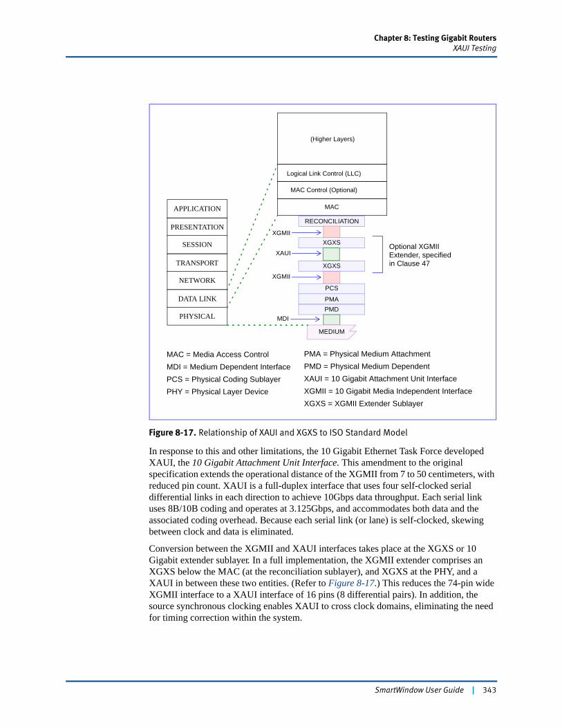
Chapter 8: Testing Gigabit RoutersXAUI Testing
Figure 8-17. Relationship of XAUI and XGXS to ISO Standard Model
In response to this and other limitations, the 10 Gigabit Ethernet Task Force developed XAUI, the 10 Gigabit Attachment Unit Interface. This amendment to the original specification extends the operational distance of the XGMII from 7 to 50 centimeters, with reduced pin count. XAUI is a full-duplex interface that uses four self-clocked serial differential links in each direction to achieve 10Gbps data throughput. Each serial link uses 8B/10B coding and operates at 3.125Gbps, and accommodates both data and the associated coding overhead. Because each serial link (or lane) is self-clocked, skewing between clock and data is eliminated.
Conversion between the XGMII and XAUI interfaces takes place at the XGXS or 10 Gigabit extender sublayer. In a full implementation, the XGMII extender comprises an XGXS below the MAC (at the reconciliation sublayer), and XGXS at the PHY, and a XAUI in between these two entities. (Refer to Figure 8-17.) This reduces the 74-pin wide XGMII interface to a XAUI interface of 16 pins (8 differential pairs). In addition, the source synchronous clocking enables XAUI to cross clock domains, eliminating the need for timing correction within the system.
APPLICATION
PRESENTATION
SESSION
TRANSPORT
NETWORK
DATA LINK
PHYSICAL
RECONCILIATION
XGXS
XGXS
PCS
PMAPMD
MEDIUM
MAC
MAC Control (Optional)
Logical Link Control (LLC)
(Higher Layers)
XAUI
XGMII
XGMII
MAC = Media Access ControlMDI = Medium Dependent InterfacePCS = Physical Coding SublayerPHY = Physical Layer Device
PMA = Physical Medium AttachmentPMD = Physical Medium DependentXAUI = 10 Gigabit Attachment Unit InterfaceXGMII = 10 Gigabit Media Independent InterfaceXGXS = XGMII Extender Sublayer
MDI
Optional XGMIIExtender, specifiedin Clause 47
SmartWindow User Guide | 343

Chapter 8: Testing Gigabit RoutersXAUI Testing
Figure 8-18 illustrates XGXS inputs and outputs. The XGMII interface is organized into four lanes of eight bits. At the source side of the XAUI interface, bytes on a lane (along with timing clock) are converted into an 8B/10B encoded data stream, then transmitted across a differential pair at 3.125 Gbps. At the destination side, the clock is recovered, and the data stream is decoded and mapped back to the 32-bit XGMII format.
Figure 8-18. XGMII to XAUI at the XGXS
Source Lane
Lane 0
Lane 1
Lane 2
Lane 3
Destination Lane
Lane 0
Lane 1
Lane 2
Lane 3
Tx Clock
Rx Data (7:0)
Rx Data (15:8)
Rx Data (23:16)
Rx Data (31:24)
Tx Clock
Tx Data (7:0)
Tx Data (15:8)
Tx Data (23:16)
Tx Data (31:24)
D0_0_P
D0_1_P
D0_2_P
D0_3_P
D0_0_N
D0_1_N
D0_2_N
D0_3_N
D1_0_P
D1_1_P
D1_2_P
D1_3_P
D1_0_N
D1_1_N
D1_2_N
D1_3_N
XGMII XGXS XAUI
344 | SmartWindow User Guide
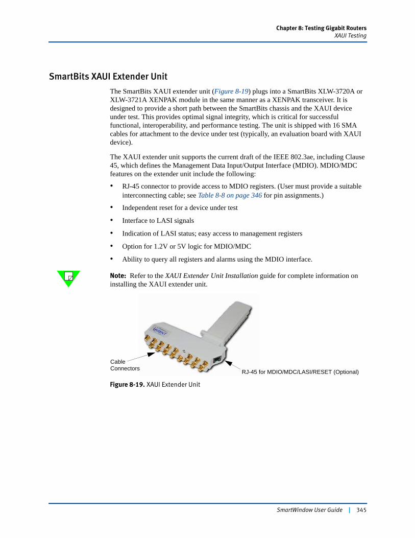
Chapter 8: Testing Gigabit RoutersXAUI Testing
SmartBits XAUI Extender Unit
The SmartBits XAUI extender unit (Figure 8-19) plugs into a SmartBits XLW-3720A or XLW-3721A XENPAK module in the same manner as a XENPAK transceiver. It is designed to provide a short path between the SmartBits chassis and the XAUI device under test. This provides optimal signal integrity, which is critical for successful functional, interoperability, and performance testing. The unit is shipped with 16 SMA cables for attachment to the device under test (typically, an evaluation board with XAUI device).
The XAUI extender unit supports the current draft of the IEEE 802.3ae, including Clause 45, which defines the Management Data Input/Output Interface (MDIO). MDIO/MDC features on the extender unit include the following:
• RJ-45 connector to provide access to MDIO registers. (User must provide a suitable interconnecting cable; see Table 8-8 on page 346 for pin assignments.)
• Independent reset for a device under test
• Interface to LASI signals
• Indication of LASI status; easy access to management registers
• Option for 1.2V or 5V logic for MDIO/MDC
• Ability to query all registers and alarms using the MDIO interface.
Note: Refer to the XAUI Extender Unit Installation guide for complete information on installing the XAUI extender unit.
Figure 8-19. XAUI Extender Unit
Cable
RJ-45 for MDIO/MDC/LASI/RESET (Optional)Connectors
SmartWindow User Guide | 345
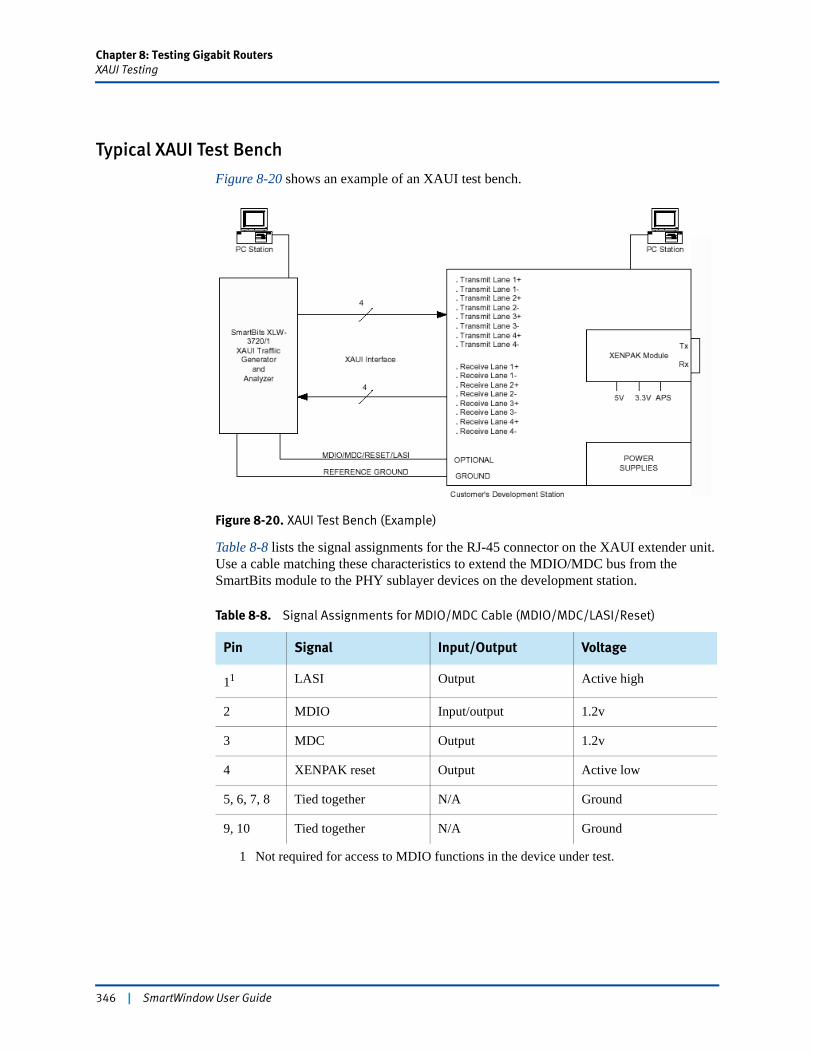
Chapter 8: Testing Gigabit RoutersXAUI Testing
Typical XAUI Test Bench
Figure 8-20 shows an example of an XAUI test bench.
Figure 8-20. XAUI Test Bench (Example)
Table 8-8 lists the signal assignments for the RJ-45 connector on the XAUI extender unit. Use a cable matching these characteristics to extend the MDIO/MDC bus from the SmartBits module to the PHY sublayer devices on the development station.
Table 8-8. Signal Assignments for MDIO/MDC Cable (MDIO/MDC/LASI/Reset)
Pin Signal Input/Output Voltage
11
1 Not required for access to MDIO functions in the device under test.
LASI Output Active high
2 MDIO Input/output 1.2v
3 MDC Output 1.2v
4 XENPAK reset Output Active low
5, 6, 7, 8 Tied together N/A Ground
9, 10 Tied together N/A Ground
346 | SmartWindow User Guide
Chapter 8: Testing Gigabit RoutersXAUI Testing
Setting up and Running XAUI Tests
You can perform XAUI testing in SmartWindow by using an XLW-3720A or XLW-3721A XENPAK module with the XAUI extender unit (ACC-3602A). (See Figure 8-19.) The extender unit plugs into the XLW-3720A/3721A module in the same manner as a XENPAK transceiver. It supports individual Bit Error Rate Tests (BERTs) of up to four XAUI channels simultaneously.
The following XAUI tests are supported:
• Individual PRBS on each of four channels simultaneously
• Measurement of frame jitter
• External clock out to sync other instruments
• Built-in CRPAT and CJPAT patterns for calculating packet error rate.
Use the following steps to run XAUI tests using SmartWindow and the XLW-3720A/3721A XENPAK modules with a XAUI extender unit.
To install the hardware:
1 Refer to the XAUI Extended Unit Installation instructions to complete physical instal-lation of the XAUI unit.
2 Attach the SMA cables between the XAUI extended unit and the device under test. (See Figure 8-20 on page 346.)
3 Attach a suitable interconnect cable between the RJ-45 connector on the XAUI unit and the development station. This cable extends the MDIO/MDC bus to the PHY sub-layer devices located on the development station. (See Figure 8-20 on page 346 and Figure 8-25 on page 353.)
To launch SmartWindow and set up the test:
1 Start SmartWindow and connect to the SmartBits chassis that contains the XENPAK module with the installed XAUI unit.
2 Reserve the module.a Right-click anywhere on the module image except the port button.b Select Reserve This Module.The corner indicator LED turns blue when the module is reserved for your use. (Refer to Chapter 3, “SmartWindow Menus” for procedures to reserve modules.)
3 Click the port button to open the Port menu. Verify that the port is set to traditional mode.
4 Ensure that the SmartMetrics Mode option is not enabled on the Port menu (Figure 8-21 on page 348).
SmartWindow User Guide | 347
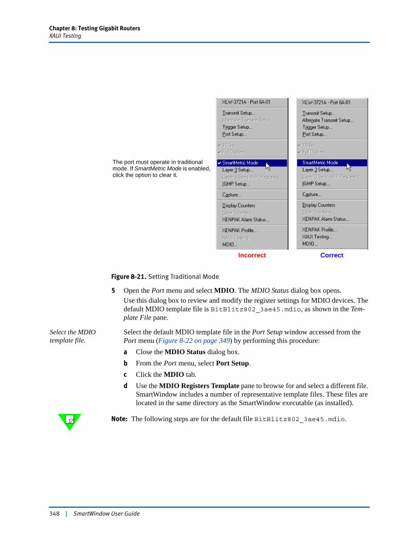
Chapter 8: Testing Gigabit RoutersXAUI Testing
Figure 8-21. Setting Traditional Mode
5 Open the Port menu and select MDIO. The MDIO Status dialog box opens.Use this dialog box to review and modify the register settings for MDIO devices. The default MDIO template file is BitBlitz802_3ae45.mdio, as shown in the Tem-plate File pane.
Select the MDIO template file.
Select the default MDIO template file in the Port Setup window accessed from the Port menu (Figure 8-22 on page 349) by performing this procedure:a Close the MDIO Status dialog box.b From the Port menu, select Port Setup.c Click the MDIO tab.d Use the MDIO Registers Template pane to browse for and select a different file.
SmartWindow includes a number of representative template files. These files are located in the same directory as the SmartWindow executable (as installed).
Note: The following steps are for the default file BitBlitz802_3ae45.mdio.
The port must operate in traditional mode. If SmartMetric Mode is enabled, click the option to clear it.
Incorrect Correct
348 | SmartWindow User Guide
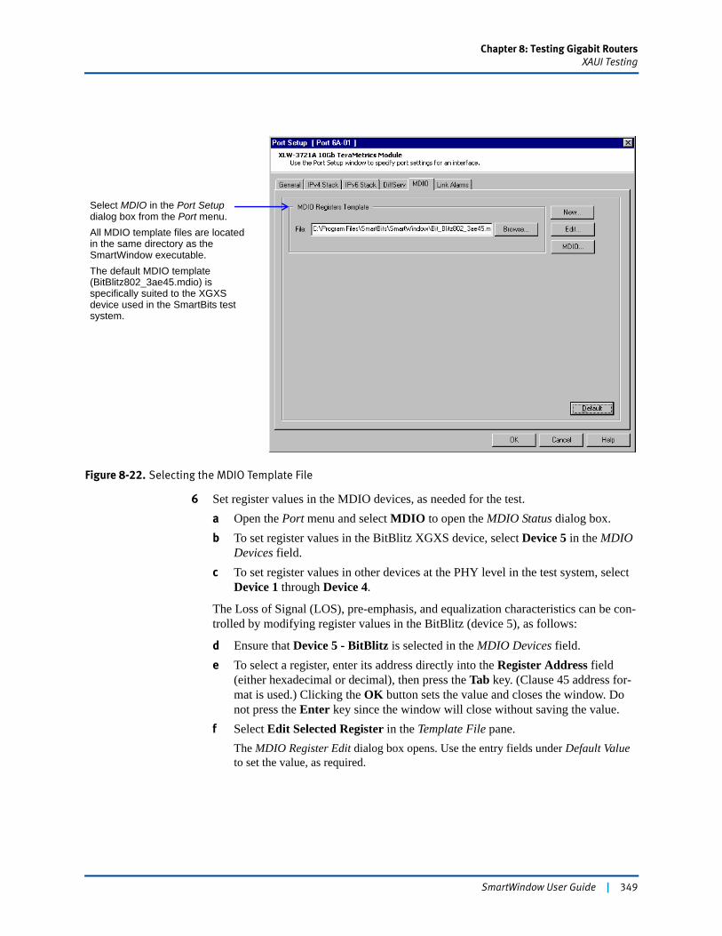
Chapter 8: Testing Gigabit RoutersXAUI Testing
Figure 8-22. Selecting the MDIO Template File
6 Set register values in the MDIO devices, as needed for the test.a Open the Port menu and select MDIO to open the MDIO Status dialog box.b To set register values in the BitBlitz XGXS device, select Device 5 in the MDIO
Devices field.c To set register values in other devices at the PHY level in the test system, select
Device 1 through Device 4.
The Loss of Signal (LOS), pre-emphasis, and equalization characteristics can be con-trolled by modifying register values in the BitBlitz (device 5), as follows:
d Ensure that Device 5 - BitBlitz is selected in the MDIO Devices field.e To select a register, enter its address directly into the Register Address field
(either hexadecimal or decimal), then press the Tab key. (Clause 45 address for-mat is used.) Clicking the OK button sets the value and closes the window. Do not press the Enter key since the window will close without saving the value.
f Select Edit Selected Register in the Template File pane.The MDIO Register Edit dialog box opens. Use the entry fields under Default Value to set the value, as required.
Select MDIO in the Port Setup dialog box from the Port menu.All MDIO template files are located in the same directory as the SmartWindow executable.The default MDIO template (BitBlitz802_3ae45.mdio) is specifically suited to the XGXS device used in the SmartBits test system.
SmartWindow User Guide | 349
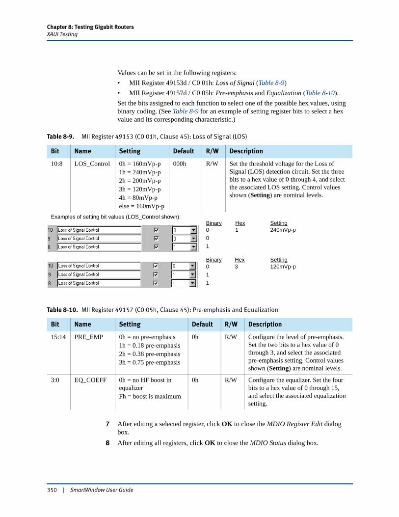
Chapter 8: Testing Gigabit RoutersXAUI Testing
Values can be set in the following registers:• MII Register 49153d / C0 01h: Loss of Signal (Table 8-9)• MII Register 49157d / C0 05h: Pre-emphasis and Equalization (Table 8-10).Set the bits assigned to each function to select one of the possible hex values, using binary coding. (See Table 8-9 for an example of setting register bits to select a hex value and its corresponding characteristic.)
7 After editing a selected register, click OK to close the MDIO Register Edit dialog box.
8 After editing all registers, click OK to close the MDIO Status dialog box.
Table 8-9. MII Register 49153 (C0 01h, Clause 45): Loss of Signal (LOS)
Bit Name Setting Default R/W Description
10:8 LOS_Control 0h = 160mVp-p1h = 240mVp-p2h = 200mVp-p3h = 120mVp-p4h = 80mVp-pelse = 160mVp-p
000h R/W Set the threshold voltage for the Loss of Signal (LOS) detection circuit. Set the three bits to a hex value of 0 through 4, and select the associated LOS setting. Control values shown (Setting) are nominal levels.
Examples of setting bit values (LOS_Control shown):Binary Hex Setting0 1 240mVp-p01
Binary Hex Setting0 3 120mVp-p11
Table 8-10. MII Register 49157 (C0 05h, Clause 45): Pre-emphasis and Equalization
Bit Name Setting Default R/W Description
15:14 PRE_EMP 0h = no pre-emphasis1h = 0.18 pre-emphasis2h = 0.38 pre-emphasis3h = 0.75 pre-emphasis
0h R/W Configure the level of pre-emphasis. Set the two bits to a hex value of 0 through 3, and select the associated pre-emphasis setting. Control values shown (Setting) are nominal levels.
3:0 EQ_COEFF 0h = no HF boost in equalizerFh = boost is maximum
0h R/W Configure the equalizer. Set the four bits to a hex value of 0 through 15, and select the associated equalization setting.
350 | SmartWindow User Guide

Chapter 8: Testing Gigabit RoutersXAUI Testing
To run the test:
1 Open the Port menu and select XAUI Testing.2 Use the XAUI dialog box to select one of the two test types:
• Jitter Pattern Generation described in “Jitter pattern test” on this page• Bit Error Test (BERT) described in “Bit error test” on page 352.
Figure 8-23. XAUI Testing Dialog
Jitter pattern test In this test, the port generates Layer 2 frames of 1,532 bytes that include the selected standard pattern or a defined custom pattern.
To run the jitter pattern test:
1 In the XAUI window, select one of the predefined patterns or define a custom pattern for the test. View the predefined patterns or edit the custom pattern by clicking the Pattern button. (Predefined patterns cannot be edited.)
2 Enter a Duration (Sec) field value.
View (but not edit) the two predefined jitter test patterns (CRPAT and CJPAT) or create a custom pattern. Select the appropriate radio button, then click the Pattern button to open the Pattern window.
For the bit error test, select the loopback point:Local DTE XS: Loopback in the XGXS DTE, the BitBlitz XGMII-to-XAUI device in the SmartBits test systemRemote PHY XS: Loopback in the XGXS PHY subsystem in the SmartBits test systemResults of the bit error test appear in the Pseudo Random Bit Stream Sequence Analysis pane.
SmartWindow User Guide | 351
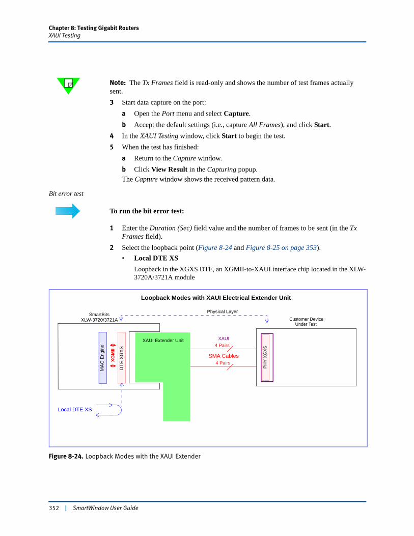
Chapter 8: Testing Gigabit RoutersXAUI Testing
Note: The Tx Frames field is read-only and shows the number of test frames actually sent.3 Start data capture on the port:
a Open the Port menu and select Capture.b Accept the default settings (i.e., capture All Frames), and click Start.
4 In the XAUI Testing window, click Start to begin the test.5 When the test has finished:
a Return to the Capture window.b Click View Result in the Capturing popup.The Capture window shows the received pattern data.
Bit error test
To run the bit error test:
1 Enter the Duration (Sec) field value and the number of frames to be sent (in the Tx Frames field).
2 Select the loopback point (Figure 8-24 and Figure 8-25 on page 353).• Local DTE XS
Loopback in the XGXS DTE, an XGMII-to-XAUI interface chip located in the XLW-3720A/3721A module
Figure 8-24. Loopback Modes with the XAUI Extender
DTE
XG
XS
SmartBitsXLW-3720/3721A
Local DTE XS
MA
C E
ngin
e 4 Pairs
4 Pairs
Physical Layer
XAUI Extender Unit
PH
Y X
GX
S
Loopback Modes with XAUI Electrical Extender Unit
SMA Cables
XGM
II
XAUI
Customer DeviceUnder Test
352 | SmartWindow User Guide
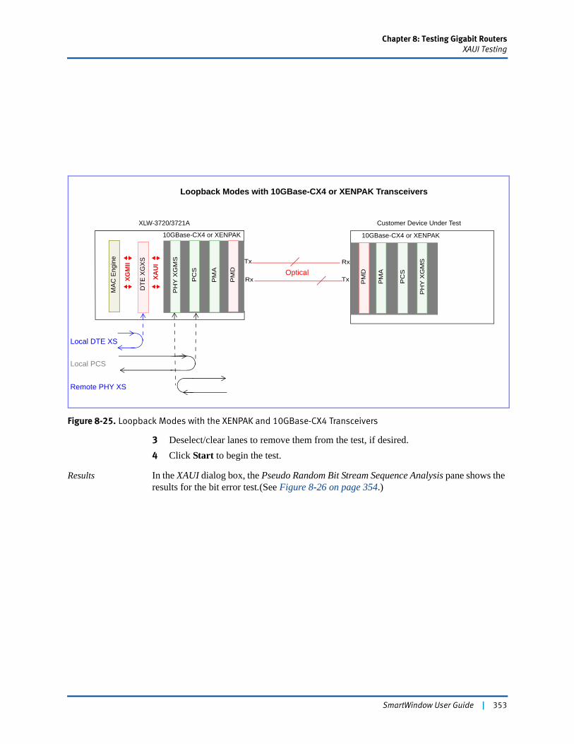
Chapter 8: Testing Gigabit RoutersXAUI Testing
Figure 8-25. Loopback Modes with the XENPAK and 10GBase-CX4 Transceivers
3 Deselect/clear lanes to remove them from the test, if desired.4 Click Start to begin the test.
Results In the XAUI dialog box, the Pseudo Random Bit Stream Sequence Analysis pane shows the results for the bit error test.(See Figure 8-26 on page 354.)
10GBase-CX4 or XENPAK
Local PCS
Local DTE XS
PM
D
PM
A
PC
S
PH
Y X
GM
S
Loopback Modes with 10GBase-CX4 or XENPAK Transceivers
10GBase-CX4 or XENPAK
Customer Device Under Test
DTE
XG
XS
MAC
Eng
ine
XGM
II
OpticalTx
RxTx
RxPM
A
PM
D
PC
S
PH
Y X
GM
S
XAU
I
Remote PHY XS
XLW-3720/3721A
SmartWindow User Guide | 353
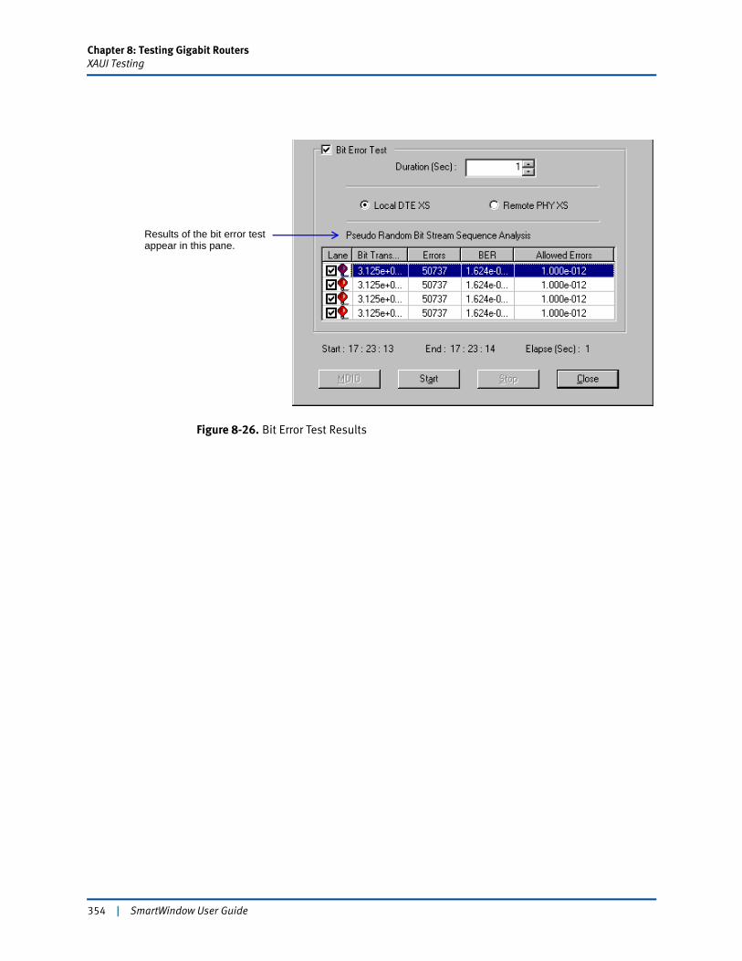
Chapter 8: Testing Gigabit RoutersXAUI Testing
Figure 8-26. Bit Error Test Results
Results of the bit error test appear in this pane.
354 | SmartWindow User Guide
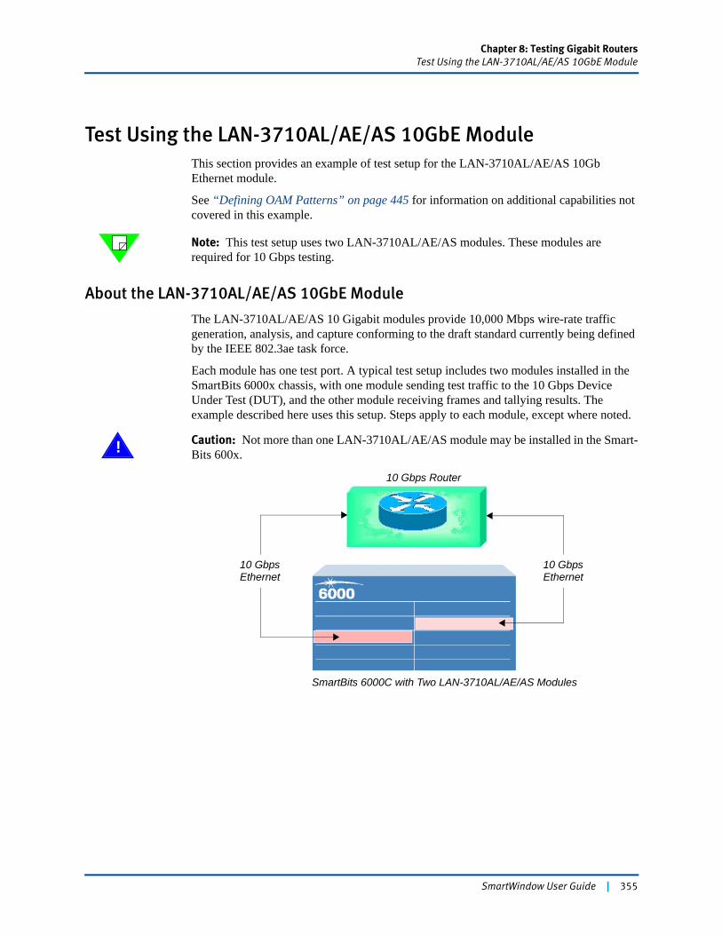
Chapter 8: Testing Gigabit RoutersTest Using the LAN-3710AL/AE/AS 10GbE Module
Test Using the LAN-3710AL/AE/AS 10GbE ModuleThis section provides an example of test setup for the LAN-3710AL/AE/AS 10Gb Ethernet module.
See “Defining OAM Patterns” on page 445 for information on additional capabilities not covered in this example.
Note: This test setup uses two LAN-3710AL/AE/AS modules. These modules are required for 10 Gbps testing.
About the LAN-3710AL/AE/AS 10GbE Module
The LAN-3710AL/AE/AS 10 Gigabit modules provide 10,000 Mbps wire-rate traffic generation, analysis, and capture conforming to the draft standard currently being defined by the IEEE 802.3ae task force.
Each module has one test port. A typical test setup includes two modules installed in the SmartBits 6000x chassis, with one module sending test traffic to the 10 Gbps Device Under Test (DUT), and the other module receiving frames and tallying results. The example described here uses this setup. Steps apply to each module, except where noted.
! Caution: Not more than one LAN-3710AL/AE/AS module may be installed in the Smart-Bits 600x.
10 Gbps Router
SmartBits 6000C with Two LAN-3710AL/AE/AS Modules
10 GbpsEthernet
10 GbpsEthernet
SmartWindow User Guide | 355
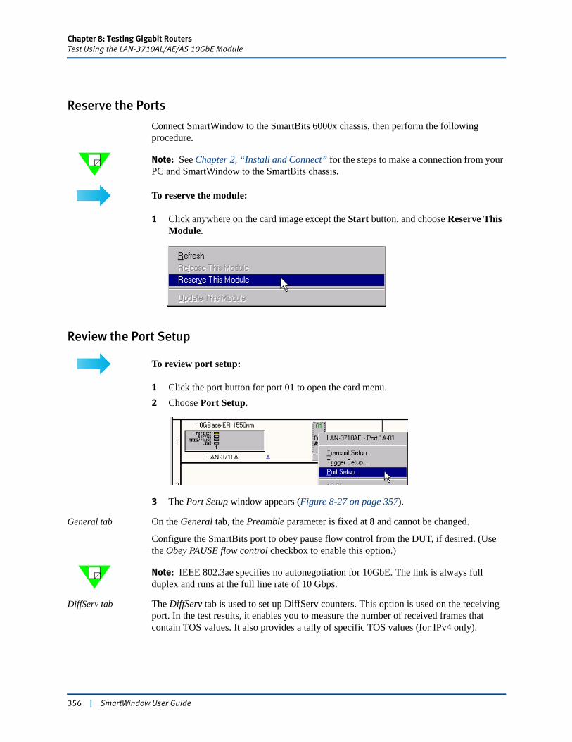
Chapter 8: Testing Gigabit RoutersTest Using the LAN-3710AL/AE/AS 10GbE Module
Reserve the Ports
Connect SmartWindow to the SmartBits 6000x chassis, then perform the following procedure.
Note: See Chapter 2, “Install and Connect” for the steps to make a connection from your PC and SmartWindow to the SmartBits chassis.
To reserve the module:
1 Click anywhere on the card image except the Start button, and choose Reserve This Module.
Review the Port Setup
To review port setup:
1 Click the port button for port 01 to open the card menu.2 Choose Port Setup.
3 The Port Setup window appears (Figure 8-27 on page 357).
General tab On the General tab, the Preamble parameter is fixed at 8 and cannot be changed.
Configure the SmartBits port to obey pause flow control from the DUT, if desired. (Use the Obey PAUSE flow control checkbox to enable this option.)
Note: IEEE 802.3ae specifies no autonegotiation for 10GbE. The link is always full duplex and runs at the full line rate of 10 Gbps.
DiffServ tab The DiffServ tab is used to set up DiffServ counters. This option is used on the receiving port. In the test results, it enables you to measure the number of received frames that contain TOS values. It also provides a tally of specific TOS values (for IPv4 only).
356 | SmartWindow User Guide
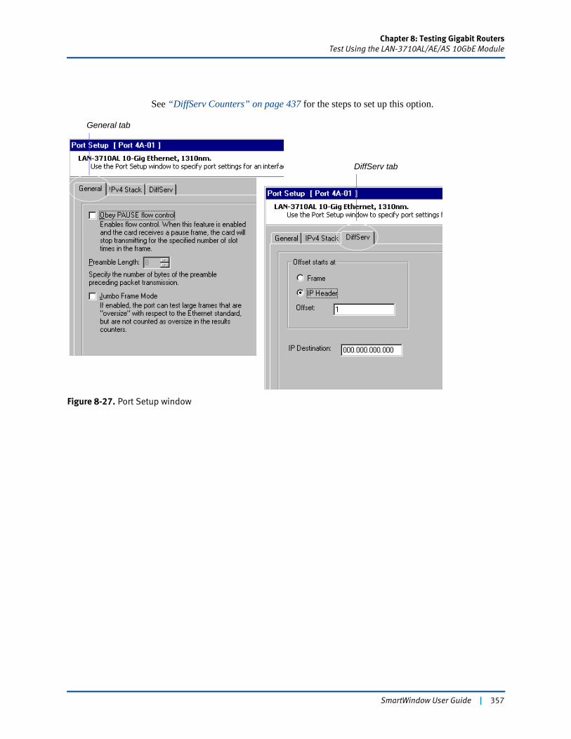
Chapter 8: Testing Gigabit RoutersTest Using the LAN-3710AL/AE/AS 10GbE Module
See “DiffServ Counters” on page 437 for the steps to set up this option.
Figure 8-27. Port Setup window
General tab
DiffServ tab
SmartWindow User Guide | 357
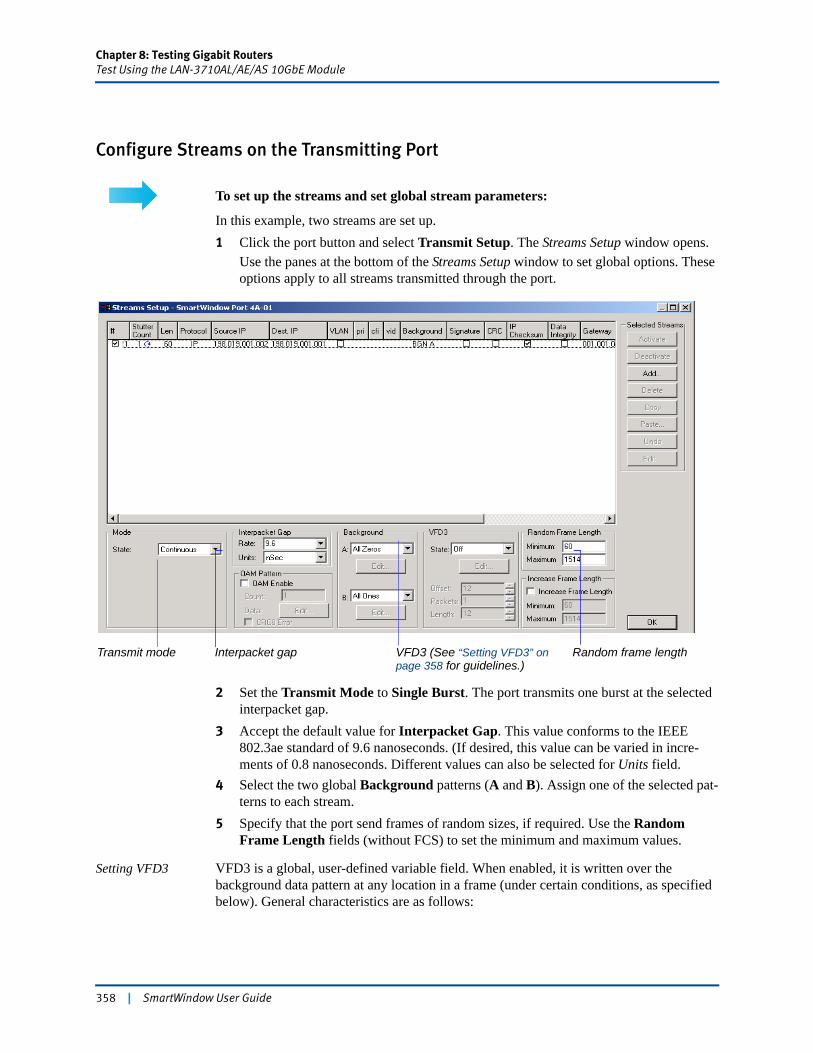
Chapter 8: Testing Gigabit RoutersTest Using the LAN-3710AL/AE/AS 10GbE Module
Configure Streams on the Transmitting Port
To set up the streams and set global stream parameters:
In this example, two streams are set up.1 Click the port button and select Transmit Setup. The Streams Setup window opens.
Use the panes at the bottom of the Streams Setup window to set global options. These options apply to all streams transmitted through the port.
2 Set the Transmit Mode to Single Burst. The port transmits one burst at the selected interpacket gap.
3 Accept the default value for Interpacket Gap. This value conforms to the IEEE 802.3ae standard of 9.6 nanoseconds. (If desired, this value can be varied in incre-ments of 0.8 nanoseconds. Different values can also be selected for Units field.
4 Select the two global Background patterns (A and B). Assign one of the selected pat-terns to each stream.
5 Specify that the port send frames of random sizes, if required. Use the Random Frame Length fields (without FCS) to set the minimum and maximum values.
Setting VFD3 VFD3 is a global, user-defined variable field. When enabled, it is written over the background data pattern at any location in a frame (under certain conditions, as specified below). General characteristics are as follows:
Transmit mode VFD3 (See “Setting VFD3” on page 358 for guidelines.)
Interpacket gap Random frame length
358 | SmartWindow User Guide

Chapter 8: Testing Gigabit RoutersTest Using the LAN-3710AL/AE/AS 10GbE Module
• VFD3 uses a buffer of 4 Kbytes. The buffer contains a number of fixed-length patterns that can be specified, and it behaves like a First-In, First-Out (FIFO) buffer. The fixed-length patterns are overlaid on the outgoing test frame. These patterns can contain different protocol data. As frames are transmitted, the VFD3 buffer cycles through the number of specified fields. When VFD3 is enabled, all transmitted streams contain VFD3 data.
• The Offset field identifies the position of the VFD3 data in the transmitted frame. The minimum offset is zero bytes. The maximum offset is equal to the desired frame length (without FCS) minus 16 bytes.
• Packets field contains the number of fixed length patterns. The minimum is 1 byte; the maximum is 512 bytes.
• Length field (without FCS) specifies the length of each data pattern. The minimum is 1 byte. The maximum is 4 Kbytes or the desired frame length minus 16 bytes.
How to select the Length value
The Length field value (without FCS) must be calculated by using the following formula, or the LAN-3710AL/AE/AE modules may generate intermittent frames with corrupted data.
Length (bytes) + Offset (bytes) <= Frame Length w/o CRC (bytes) – 16 bytes
Examples:Offset = 0 bytes
Frame Length with CRC = 95 bytes
Frame Length without CRC = 91 bytes
Maximum VFD3 Length = 75 bytes
Offset = 0 bytes
Frame Length with CRC = 100 bytes
Frame Length without CRC = 96 bytes
Maximum VFD3 Length = 80 bytes
SmartWindow User Guide | 359
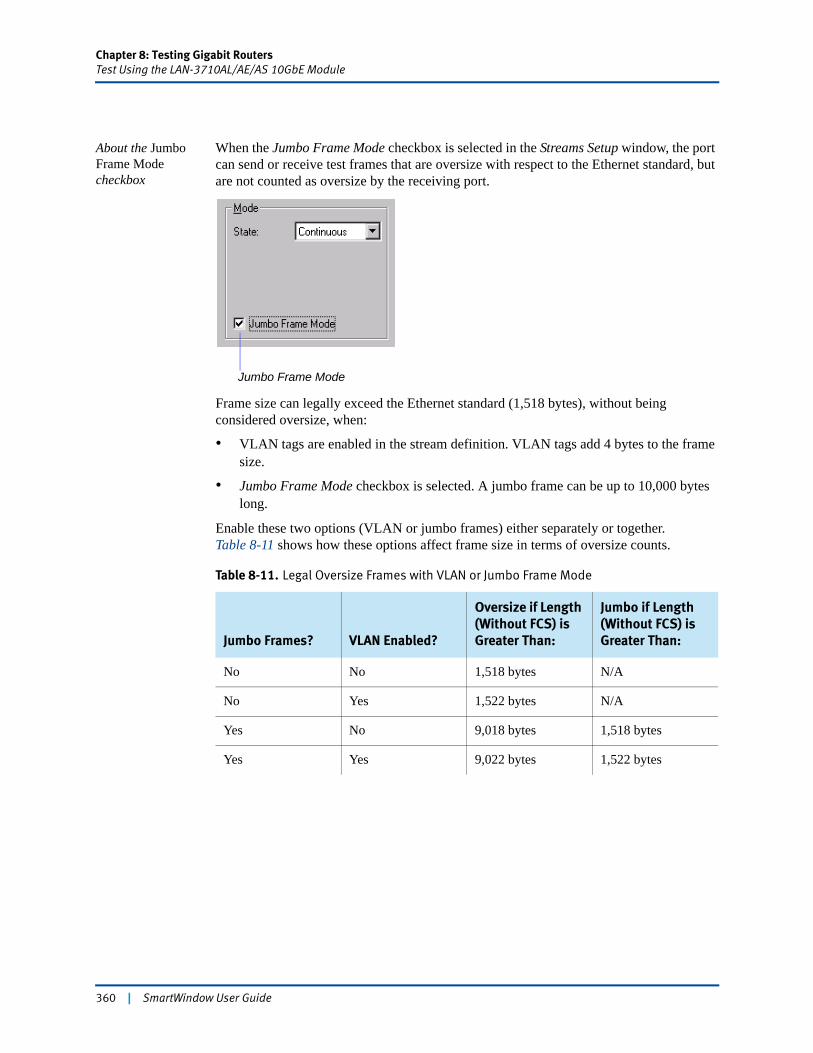
Chapter 8: Testing Gigabit RoutersTest Using the LAN-3710AL/AE/AS 10GbE Module
About the Jumbo Frame Mode checkbox
When the Jumbo Frame Mode checkbox is selected in the Streams Setup window, the port can send or receive test frames that are oversize with respect to the Ethernet standard, but are not counted as oversize by the receiving port.
Frame size can legally exceed the Ethernet standard (1,518 bytes), without being considered oversize, when:
• VLAN tags are enabled in the stream definition. VLAN tags add 4 bytes to the frame size.
• Jumbo Frame Mode checkbox is selected. A jumbo frame can be up to 10,000 bytes long.
Enable these two options (VLAN or jumbo frames) either separately or together. Table 8-11 shows how these options affect frame size in terms of oversize counts.
Table 8-11. Legal Oversize Frames with VLAN or Jumbo Frame Mode
Jumbo Frames? VLAN Enabled?
Oversize if Length (Without FCS) is Greater Than:
Jumbo if Length (Without FCS) is Greater Than:
No No 1,518 bytes N/A
No Yes 1,522 bytes N/A
Yes No 9,018 bytes 1,518 bytes
Yes Yes 9,022 bytes 1,522 bytes
Jumbo Frame Mode
360 | SmartWindow User Guide
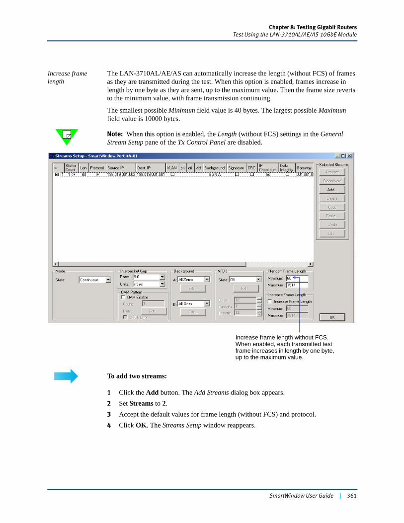
Chapter 8: Testing Gigabit RoutersTest Using the LAN-3710AL/AE/AS 10GbE Module
Increase frame length
The LAN-3710AL/AE/AS can automatically increase the length (without FCS) of frames as they are transmitted during the test. When this option is enabled, frames increase in length by one byte as they are sent, up to the maximum value. Then the frame size reverts to the minimum value, with frame transmission continuing.
The smallest possible Minimum field value is 40 bytes. The largest possible Maximum field value is 10000 bytes.
Note: When this option is enabled, the Length (without FCS) settings in the General Stream Setup pane of the Tx Control Panel are disabled.
To add two streams:
1 Click the Add button. The Add Streams dialog box appears.2 Set Streams to 2.3 Accept the default values for frame length (without FCS) and protocol.4 Click OK. The Streams Setup window reappears.
Increase frame length without FCS. When enabled, each transmitted test frame increases in length by one byte, up to the maximum value.
SmartWindow User Guide | 361
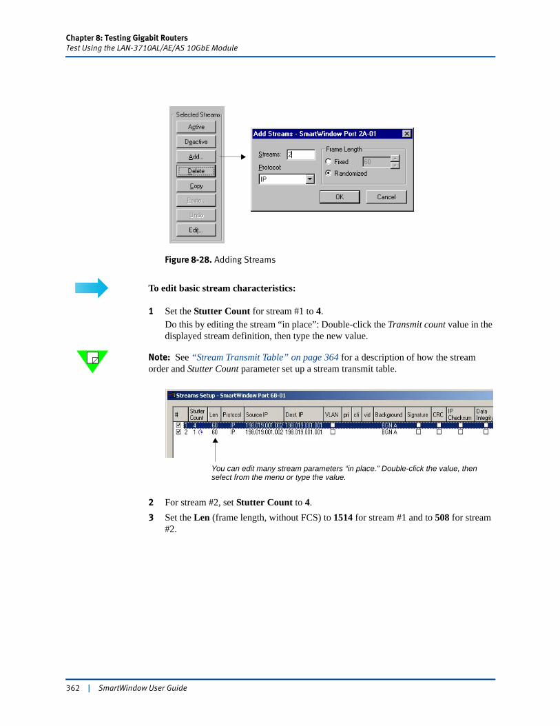
Chapter 8: Testing Gigabit RoutersTest Using the LAN-3710AL/AE/AS 10GbE Module
Figure 8-28. Adding Streams
To edit basic stream characteristics:
1 Set the Stutter Count for stream #1 to 4.Do this by editing the stream “in place”: Double-click the Transmit count value in the displayed stream definition, then type the new value.
Note: See “Stream Transmit Table” on page 364 for a description of how the stream order and Stutter Count parameter set up a stream transmit table.
2 For stream #2, set Stutter Count to 4.3 Set the Len (frame length, without FCS) to 1514 for stream #1 and to 508 for stream
#2.
You can edit many stream parameters “in place.” Double-click the value, then select from the menu or type the value.
362 | SmartWindow User Guide
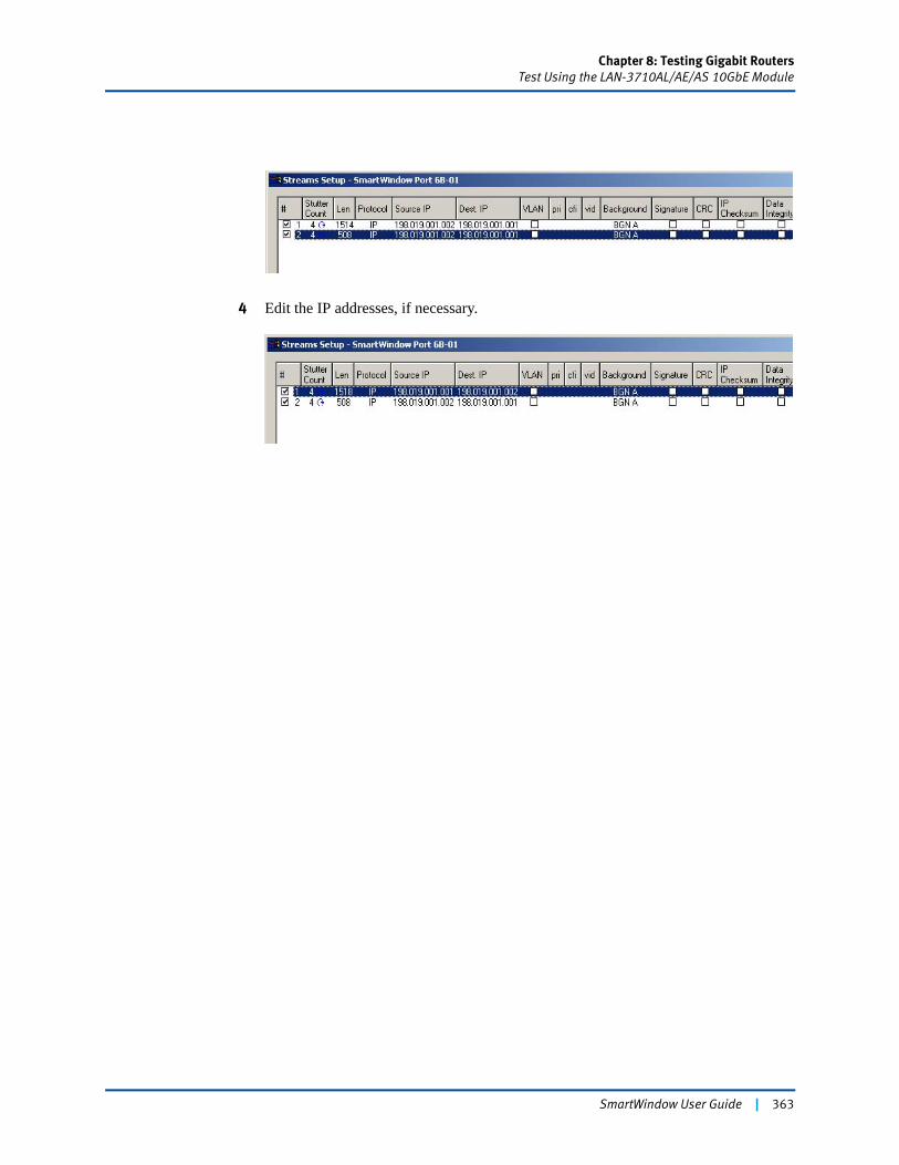
Chapter 8: Testing Gigabit RoutersTest Using the LAN-3710AL/AE/AS 10GbE Module
4 Edit the IP addresses, if necessary.
SmartWindow User Guide | 363

Chapter 8: Testing Gigabit RoutersTest Using the LAN-3710AL/AE/AS 10GbE Module
Stream Transmit Table
When streams are added and values set in the Stutter Count field, you establish:
• The order in which streams are transmitted
• How many times each stream is transmitted in its turn.
In this example, two streams are set up, each with a Stutter Count field value of 4. As a result, the frames sent by the transmitting port follow the order shown below:
A more complicated stream table might set a variety of frame characteristics and repetitions per transmit cycle. As an example:
Transmit table = Order of streams and Stutter Count value for each stream
1 1 1 1 2 2 2 2
In this example, the order of test frames sent by the transmitting port (by stream #) is:
1
3
2 2 2 2
444 4
(continues through Stream 8)
44 44
3
2
4
1 1 11
364 | SmartWindow User Guide
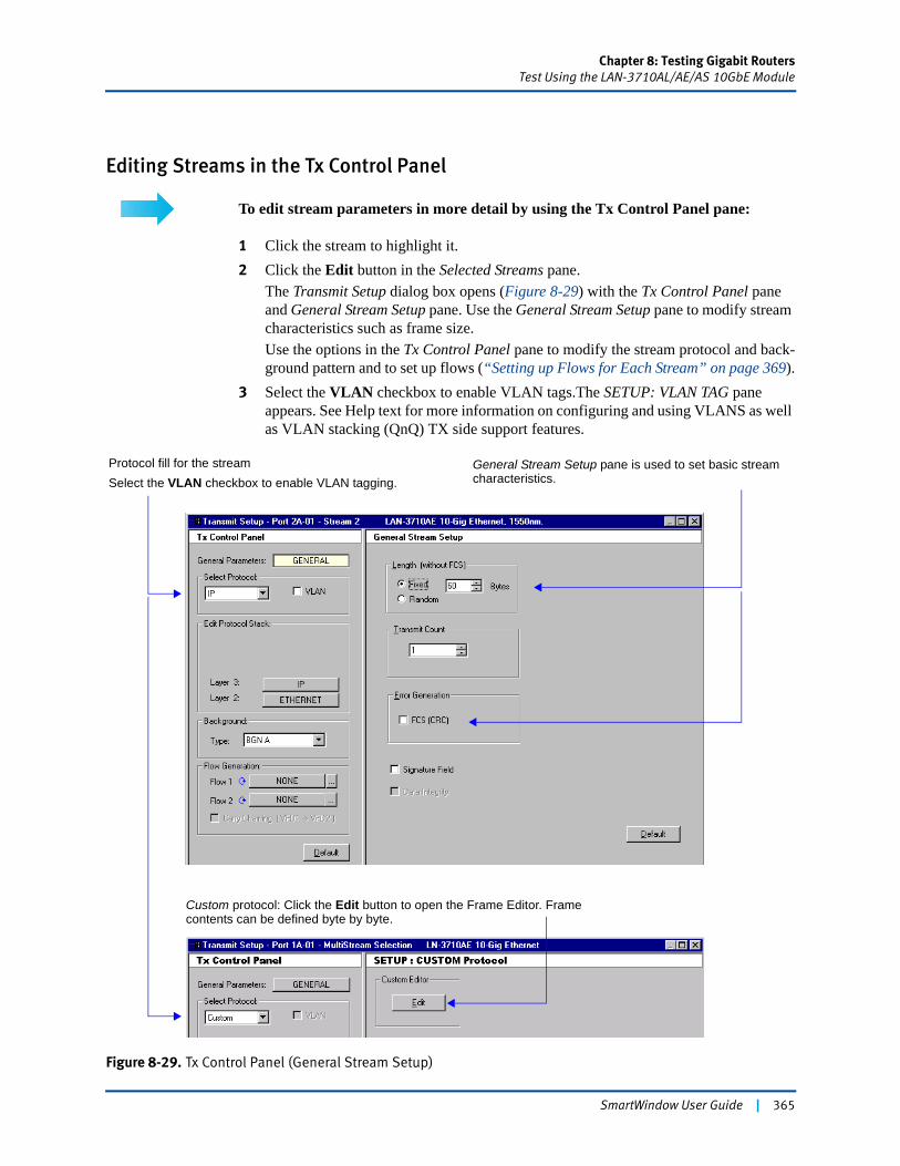
Chapter 8: Testing Gigabit RoutersTest Using the LAN-3710AL/AE/AS 10GbE Module
Editing Streams in the Tx Control Panel
To edit stream parameters in more detail by using the Tx Control Panel pane:
1 Click the stream to highlight it.2 Click the Edit button in the Selected Streams pane.
The Transmit Setup dialog box opens (Figure 8-29) with the Tx Control Panel pane and General Stream Setup pane. Use the General Stream Setup pane to modify stream characteristics such as frame size.Use the options in the Tx Control Panel pane to modify the stream protocol and back-ground pattern and to set up flows (“Setting up Flows for Each Stream” on page 369).
3 Select the VLAN checkbox to enable VLAN tags.The SETUP: VLAN TAG pane appears. See Help text for more information on configuring and using VLANS as well as VLAN stacking (QnQ) TX side support features.
Figure 8-29. Tx Control Panel (General Stream Setup)
General Stream Setup pane is used to set basic stream characteristics.
Protocol fill for the streamSelect the VLAN checkbox to enable VLAN tagging.
Custom protocol: Click the Edit button to open the Frame Editor. Frame contents can be defined byte by byte.
SmartWindow User Guide | 365
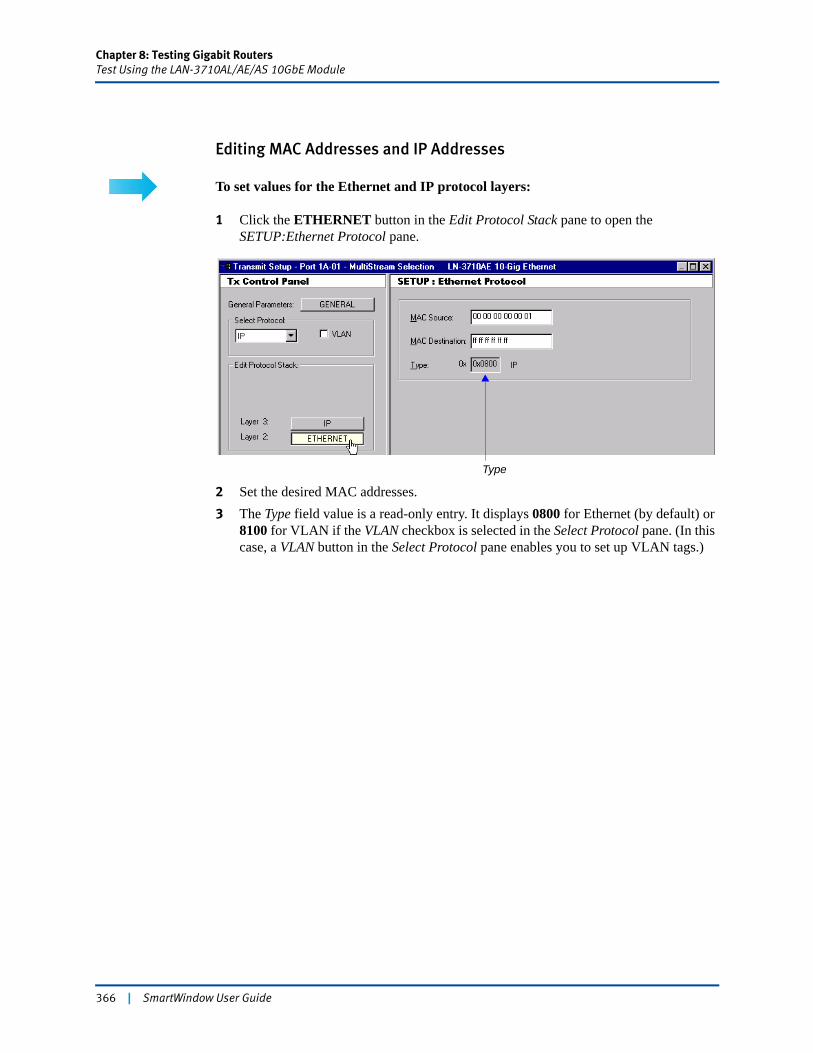
Chapter 8: Testing Gigabit RoutersTest Using the LAN-3710AL/AE/AS 10GbE Module
Editing MAC Addresses and IP Addresses
To set values for the Ethernet and IP protocol layers:
1 Click the ETHERNET button in the Edit Protocol Stack pane to open the SETUP:Ethernet Protocol pane.
2 Set the desired MAC addresses.3 The Type field value is a read-only entry. It displays 0800 for Ethernet (by default) or
8100 for VLAN if the VLAN checkbox is selected in the Select Protocol pane. (In this case, a VLAN button in the Select Protocol pane enables you to set up VLAN tags.)
Type
366 | SmartWindow User Guide
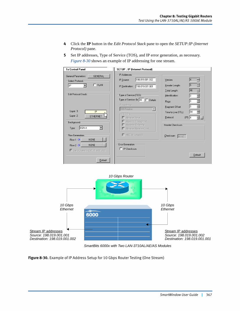
Chapter 8: Testing Gigabit RoutersTest Using the LAN-3710AL/AE/AS 10GbE Module
4 Click the IP button in the Edit Protocol Stack pane to open the SETUP:IP (Internet Protocol) pane.
5 Set IP addresses, Type of Service (TOS), and IP error generation, as necessary.Figure 8-30 shows an example of IP addressing for one stream.
Figure 8-30. Example of IP Address Setup for 10 Gbps Router Testing (One Stream)
10 Gbps Router
SmartBits 6000x with Two LAN-3710AL/AE/AS Modules
10 GbpsEthernet
10 GbpsEthernet
Stream IP addressesSource: 198.019.001.001Destination: 198.019.001.002
Stream IP addressesSource: 198.019.001.002Destination: 198.019.001.001
SmartWindow User Guide | 367
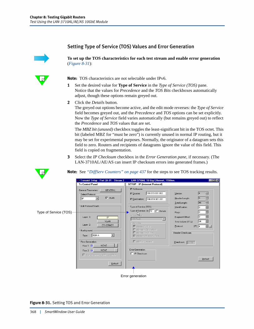
Chapter 8: Testing Gigabit RoutersTest Using the LAN-3710AL/AE/AS 10GbE Module
Setting Type of Service (TOS) Values and Error Generation
To set up the TOS characteristics for each test stream and enable error generation (Figure 8-31):
Note: TOS characteristics are not selectable under IPv6.1 Set the desired value for Type of Service in the Type of Service (TOS) pane.
Notice that the values for Precedence and the TOS Bits checkboxes automatically adjust, though these options remain greyed out.
2 Click the Details button. The greyed out options become active, and the edit mode reverses: the Type of Service field becomes greyed out, and the Precedence and TOS options can be set explicitly. Now the Type of Service field varies automatically (but remains greyed out) to reflect the Precedence and TOS values that are set.The MBZ bit (unused) checkbox toggles the least-significant bit in the TOS octet. This bit (labeled MBZ for “must be zero”) is currently unused in normal IP routing, but it may be set for experimental purposes. Normally, the originator of a datagram sets this field to zero. Routers and recipients of datagrams ignore the value of this field. This field is copied on fragmentation.
3 Select the IP Checksum checkbox in the Error Generation pane, if necessary. (The LAN-3710AL/AE/AS can insert IP checksum errors into generated frames.)
Note: See “DiffServ Counters” on page 437 for the steps to see TOS tracking results.
Figure 8-31. Setting TOS and Error Generation
Type of Service (TOS)
Error generation
368 | SmartWindow User Guide
Chapter 8: Testing Gigabit RoutersTest Using the LAN-3710AL/AE/AS 10GbE Module
Setting up Flows for Each Stream
You can configure each stream to cycle through up to 16,777,215 flows.
With IP streams, flow generation can be based on IP source or destination address or on VFD fields. With UDP or TCP streams, flow generation can be based on source or destination IP address, or on source or destination port number.
To set up flows for each stream:
1 Select (click) the stream in the Streams Setup window.2 Click the Edit button.3 In the Flow Generation pane of the Tx Control Panel pane (Figure 8-32 on page 370),
select the variable to use with flow 1.The SETUP FLOWS pane changes to show the options for the selected variable. For example, in Figure 8-32 on page 370, the Select Protocol field value is IP and the generation variable for Flow 1 is IP ADDR. SOURCE. The SETUP FLOWS: IP Source Address pane shows the options related to this choice.
4 Set values in the related SETUP FLOWS pane.
Note: See the following notes for additional guidelines:• For IP protocol streams, see “Setting Up IP Flows” below.• For UDP or TCP protocol streams, see “Setting Up Layer 4 Flows (UDP or
TCP)” on page 370.
Setting Up IP Flows
When the Vary: Host Address button is clicked in the Setup Flows pane, you can also select the Skip Subnet and Broadcast Addresses checkbox. Each transmitted frame then increments the selected IP address by 1 (the Step value), skipping 0 and 255, and starting with the IP address set in the Start Address field. When all addresses have been cycled through, the process starts again with the initial IP address.
The Count field has a maximum value of 16,777,215.
The Subnet Mask Length (/n) field has a maximum value of 30 bits.
When the Vary: Subnet Address button is clicked in the Setup Flows pane, the Count field value varies automatically according to the Subnet Mask Length (/n) field value.
Use the Resulting Flows pane to review the proposed configuration, in terms of starting address, ending address, and total number of flows.
Click the OK button when settings are correct.
SmartWindow User Guide | 369
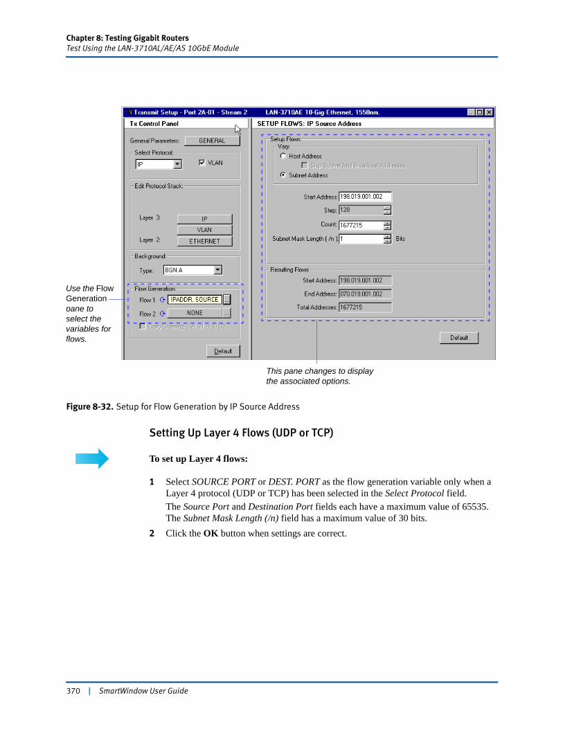
Chapter 8: Testing Gigabit RoutersTest Using the LAN-3710AL/AE/AS 10GbE Module
Figure 8-32. Setup for Flow Generation by IP Source Address
Setting Up Layer 4 Flows (UDP or TCP)
To set up Layer 4 flows:
1 Select SOURCE PORT or DEST. PORT as the flow generation variable only when a Layer 4 protocol (UDP or TCP) has been selected in the Select Protocol field.The Source Port and Destination Port fields each have a maximum value of 65535. The Subnet Mask Length (/n) field has a maximum value of 30 bits.
2 Click the OK button when settings are correct.
Use the Flow Generation pane to select the variables for flows.
This pane changes to display the associated options.
370 | SmartWindow User Guide
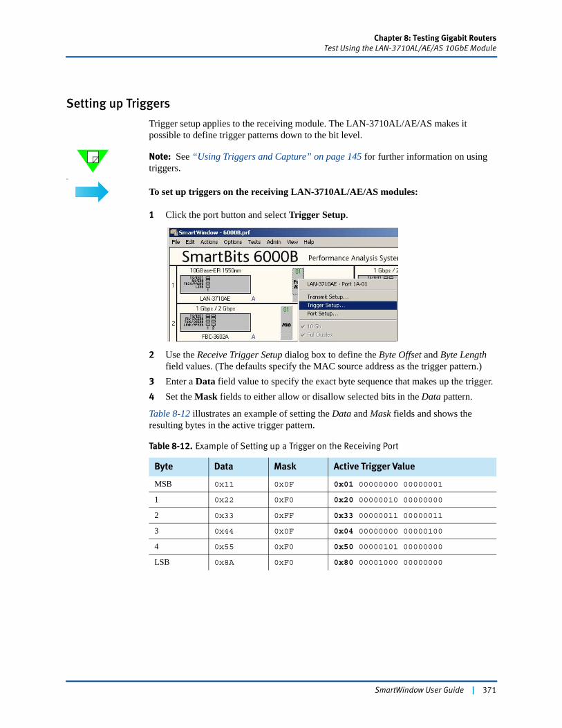
Chapter 8: Testing Gigabit RoutersTest Using the LAN-3710AL/AE/AS 10GbE Module
Setting up Triggers
Trigger setup applies to the receiving module. The LAN-3710AL/AE/AS makes it possible to define trigger patterns down to the bit level.
Note: See “Using Triggers and Capture” on page 145 for further information on using triggers.
Us
To set up triggers on the receiving LAN-3710AL/AE/AS modules:
1 Click the port button and select Trigger Setup.
2 Use the Receive Trigger Setup dialog box to define the Byte Offset and Byte Length field values. (The defaults specify the MAC source address as the trigger pattern.)
3 Enter a Data field value to specify the exact byte sequence that makes up the trigger.4 Set the Mask fields to either allow or disallow selected bits in the Data pattern.
Table 8-12 illustrates an example of setting the Data and Mask fields and shows the resulting bytes in the active trigger pattern.
Table 8-12. Example of Setting up a Trigger on the Receiving Port
Byte Data Mask Active Trigger Value
MSB 0x11 0x0F 0x01 00000000 00000001
1 0x22 0xF0 0x20 00000010 00000000
2 0x33 0xFF 0x33 00000011 00000011
3 0x44 0x0F 0x04 00000000 00000100
4 0x55 0xF0 0x50 00000101 00000000
LSB 0x8A 0xF0 0x80 00001000 00000000
SmartWindow User Guide | 371
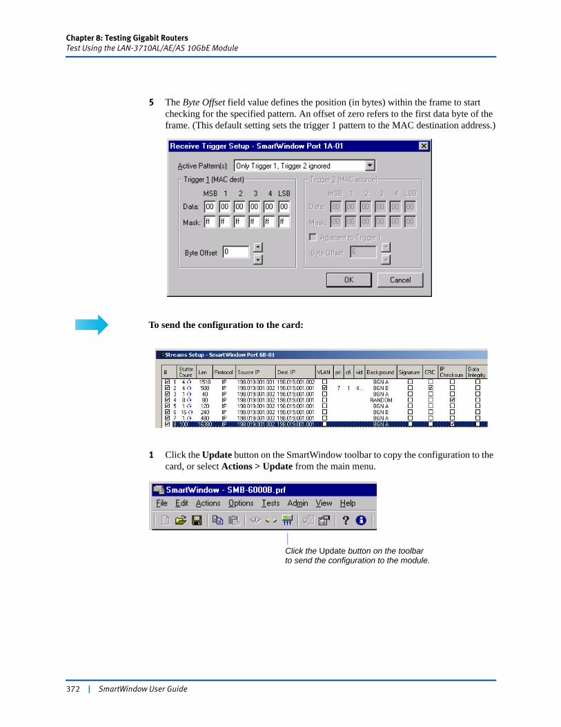
Chapter 8: Testing Gigabit RoutersTest Using the LAN-3710AL/AE/AS 10GbE Module
5 The Byte Offset field value defines the position (in bytes) within the frame to start checking for the specified pattern. An offset of zero refers to the first data byte of the frame. (This default setting sets the trigger 1 pattern to the MAC destination address.)
To send the configuration to the card:
1 Click the Update button on the SmartWindow toolbar to copy the configuration to the card, or select Actions > Update from the main menu.
Click the Update button on the toolbarto send the configuration to the module.
372 | SmartWindow User Guide
Chapter 8: Testing Gigabit RoutersTest Using the LAN-3710AL/AE/AS 10GbE Module
To configure the Gigabit setup and IP addresses of the receiving card:
The line interface and the IP addresses on the receiving card need to be configured. However, streams do not need to be created unless there will be two-way transmission and reception.1 Repeat the procedures described for the transmitting module in “Configure Streams
on the Transmitting Port” on page 358 to configure a card to receive.
Set up the DUT
Refer to “Configuring the DUT” on page 413 for a description of how to set up the DUT.
Send Traffic and View Counters
Now you are ready to transmit traffic and view counters. Refer to “Running SmartCounters” on page 435.
Note: See also “DiffServ Counters” on page 437 for information regarding the results of DiffServ tracking on the receiving port.
SmartWindow User Guide | 373
Chapter 8: Testing Gigabit RoutersTest Using the LAN-3311A TeraMetrics Module
Test Using the LAN-3311A TeraMetrics ModuleThis section provides an example of test setup for the LAN-3311A TeraMetrics module. Refer to “Testing Gigabit Routers with SmartMetrics” on page 316 for an overview. This section covers the following topics:
• “Gigabit Setup” on page 375
• “Layer 3 Setup” on page 377
• “Configure Streams on the Transmitting Card” on page 378
• “Set up the DUT” on page 379
• “Send Traffic and View Counters” on page 379.
For additional information on the configuration process, see the following topics:
• “Configuring Transmit Streams on TeraMetrics Modules” on page 392
• “Configuring SmartCounters” on page 415.
Note: This test setup uses the LAN-3311A. Additional cards and modules that support this test include the following:
• WAN-3415/3420 over frame relay
• LAN-3200A/As
• ML-7710
• LAN-3101A/B as ping target.
About the LAN-3311A TeraMetrics Module
The GBIC-based LAN-3311A TeraMetrics module supports 1,000 Mbps over single- and multi-mode fiber. The module is capable of simulating the millions of client and server sessions required to fully test network systems, yielding per-flow metrics for billions of IP flows. It complies with the IEEE 802.3z draft specification in Gigabit mode.
The module features SmartMetrics test support for per-flow frame loss, latency, latency and sequence, and latency distribution tracking. Capabilities include:• Stream-based, wire-rate traffic generation and analysis at up to 1,448,095 frames per
second, with frame sizes of 64 to 16,384 bytes.• Ports that are completely independent in operation. • Full-duplex operation.• Support for autonegotiation.• Up to 512 independent IP streams (peer-to-peer), with analysis of up to 64K streams.
Instruments a nearly unlimited number of flows per stream, thereby stressing a router by having it perform a different routing decision for every frame. (See Table 5-13 on
374 | SmartWindow User Guide
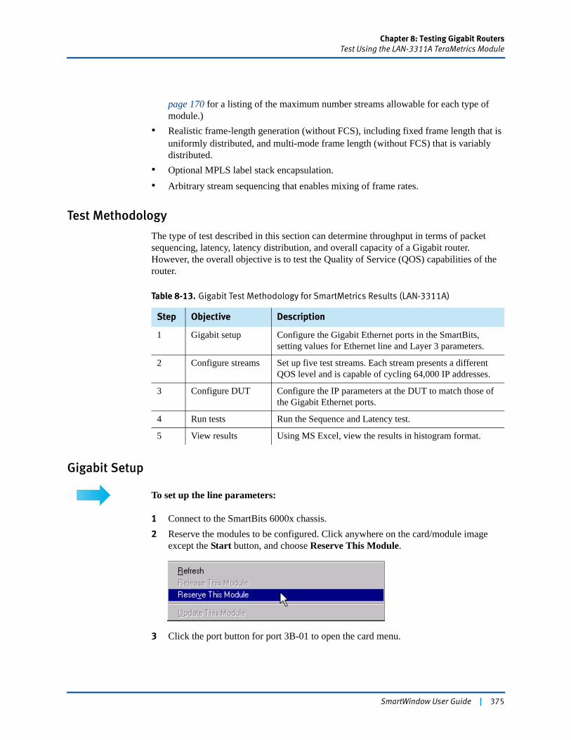
Chapter 8: Testing Gigabit RoutersTest Using the LAN-3311A TeraMetrics Module
page 170 for a listing of the maximum number streams allowable for each type of module.)
• Realistic frame-length generation (without FCS), including fixed frame length that is uniformly distributed, and multi-mode frame length (without FCS) that is variably distributed.
• Optional MPLS label stack encapsulation. • Arbitrary stream sequencing that enables mixing of frame rates.
Test Methodology
The type of test described in this section can determine throughput in terms of packet sequencing, latency, latency distribution, and overall capacity of a Gigabit router. However, the overall objective is to test the Quality of Service (QOS) capabilities of the router.
Gigabit Setup
To set up the line parameters:
1 Connect to the SmartBits 6000x chassis.2 Reserve the modules to be configured. Click anywhere on the card/module image
except the Start button, and choose Reserve This Module.
3 Click the port button for port 3B-01 to open the card menu.
Table 8-13. Gigabit Test Methodology for SmartMetrics Results (LAN-3311A)
Step Objective Description
1 Gigabit setup Configure the Gigabit Ethernet ports in the SmartBits, setting values for Ethernet line and Layer 3 parameters.
2 Configure streams Set up five test streams. Each stream presents a different QOS level and is capable of cycling 64,000 IP addresses.
3 Configure DUT Configure the IP parameters at the DUT to match those of the Gigabit Ethernet ports.
4 Run tests Run the Sequence and Latency test.
5 View results Using MS Excel, view the results in histogram format.
SmartWindow User Guide | 375
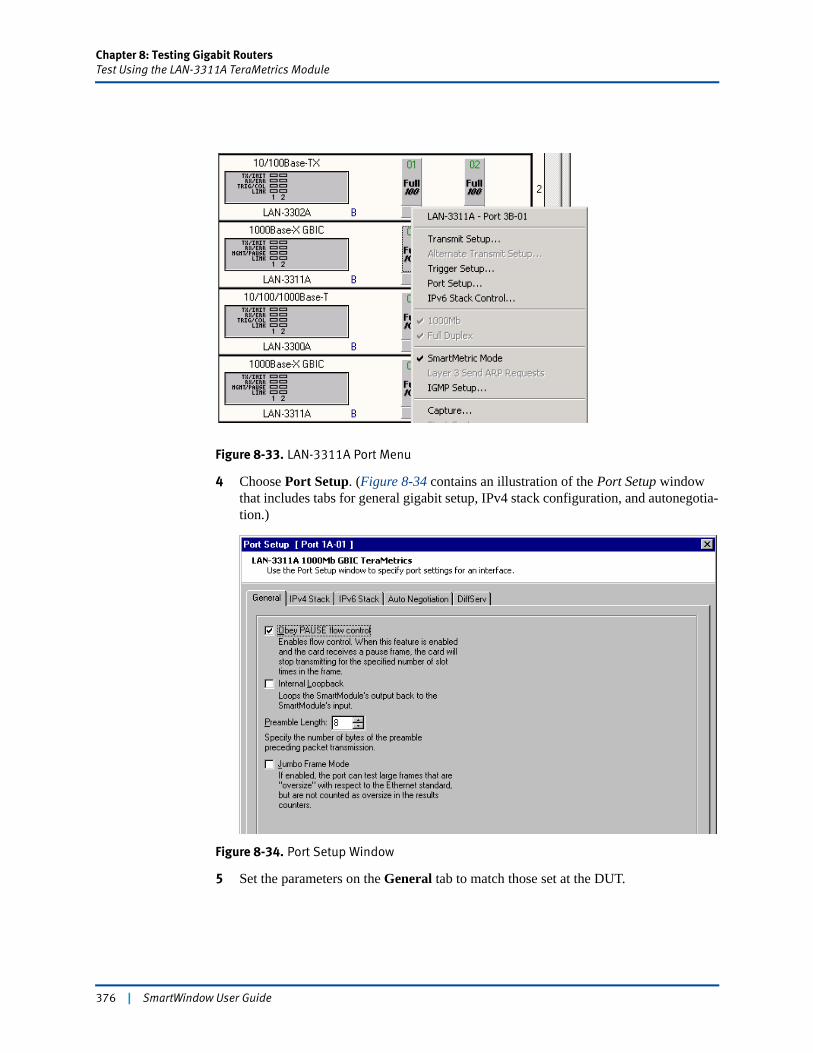
Chapter 8: Testing Gigabit RoutersTest Using the LAN-3311A TeraMetrics Module
Figure 8-33. LAN-3311A Port Menu
4 Choose Port Setup. (Figure 8-34 contains an illustration of the Port Setup window that includes tabs for general gigabit setup, IPv4 stack configuration, and autonegotia-tion.)
Figure 8-34. Port Setup Window
5 Set the parameters on the General tab to match those set at the DUT.
376 | SmartWindow User Guide
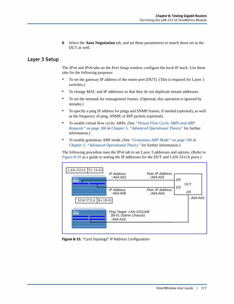
Chapter 8: Testing Gigabit RoutersTest Using the LAN-3311A TeraMetrics Module
6 Select the Auto Negotiation tab, and set these parameteres to match those set at the DUT as well.
Layer 3 Setup
The IPv4 and IPv6 tabs on the Port Setup window configure the local IP stack. Use these tabs for the following purposes:
• To set the gateway IP address of the router port (DUT). (This is required for Layer 3 switches.)
• To change MAC and IP addresses so that they do not duplicate stream addresses.
• To set the netmask for management frames. (Optional; this operation is ignored by streams.)
• To specify a ping IP address for pings and SNMP frames, if needed (optional), as well as the frequency of ping, SNMP, or RIP packets (optional).
• To enable virtual flow cyclic ARPs. (See “Virtual Flow Cyclic ARPs and ARP Requests” on page 186 in Chapter 5, “Advanced Operational Theory” for further information.)
• To enable gratuitous ARP mode. (See “Gratuitous ARP Mode” on page 196 in Chapter 5, “Advanced Operational Theory” for further information.)
The following procedure uses the IPv6 tab to set Layer 3 addresses and options. (Refer to Figure 8-35 as a guide to setting the IP addresses for the DUT and LAN-3311A ports.)
Figure 8-35. “Card Topology” IP Address Configuration
DUT
IP Address
Peer IP Address
Ping Target: LAN-3101A/B
::A64:A01
::A64:A0A
2B-01 (Same Chassis)
IP Address192.0.0.2
Peer IP Address::A64:A02
0/0
1/02/0
::A64:A03
Tx 1A-01LAN-3311A
Rx 1B-01XLW-3721A
IP Address192.0.0.2
IP Address::A64:A09
::A64:A19
SmartWindow User Guide | 377
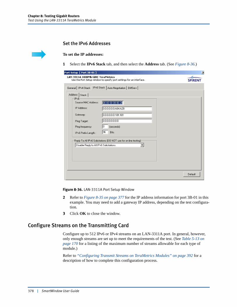
Chapter 8: Testing Gigabit RoutersTest Using the LAN-3311A TeraMetrics Module
Set the IPv6 Addresses
To set the IP addresses:
1 Select the IPv6 Stack tab, and then select the Address tab. (See Figure 8-36.)
Figure 8-36. LAN-3311A Port Setup Window
2 Refer to Figure 8-35 on page 377 for the IP address information for port 3B-01 in this example. You may need to add a gateway IP address, depending on the test configura-tion.
3 Click OK to close the window.
Configure Streams on the Transmitting Card
Configure up to 512 IPv6 or IPv4 streams on an LAN-3311A port. In general, however, only enough streams are set up to meet the requirements of the test. (See Table 5-13 on page 170 for a listing of the maximum number of streams allowable for each type of module.)
Refer to “Configuring Transmit Streams on TeraMetrics Modules” on page 392 for a description of how to complete this configuration process.
378 | SmartWindow User Guide

Chapter 8: Testing Gigabit RoutersTest Using the LAN-3311A TeraMetrics Module
Set up the DUT
Refer to “Configuring the DUT” on page 413 for a description of how to set up the DUT.
Send Traffic and View Counters
Now you are ready to transmit traffic and view counters. Proceed to “Running SmartCounters” on page 435 for steps.
SmartWindow User Guide | 379

Chapter 8: Testing Gigabit RoutersTest Using the LAN-3201B/C SmartMetrics Module
Test Using the LAN-3201B/C SmartMetrics ModuleRefer to “Testing Gigabit Routers with SmartMetrics” on page 316 for an overview of test setup and methodology.
This section covers the following topics:
• “About the LAN-3201B/C SmartMetrics Module” on page 380
• “Gigabit Setup” on page 382
• “Layer 3 Setup” on page 383
• “Configure Streams on the Transmitting Card” on page 384
• “Set up the DUT” on page 379
• “Send Traffic and View Counters” on page 379.
Note: This test setup uses the LAN-3201B/C. Additional cards and modules that support this test include the following:
• WAN-3415/3420 over frame relay
• LAN-3200A/As
• ML-7710
• LAN-3101A/B as ping target.
About the LAN-3201B/C SmartMetrics Module
The LAN-3201B/C 1000Base-SX is a multilayer SmartMetrics module for the SmartBits 600x/6000x chassis. Use the module to test Layer 3 as well as Layer 2 functionality and performance in Gigabit Ethernet routers. The module is designed to evaluate key performance parameters under typical or extreme traffic load conditions.
The LAN-3201B/C is capable of full-wire traffic generation and analysis. It features:
• A 850nm ShortWave multi-mode fiber physical interface
• 802.1p, 802.1q, and 802.3 ac VLAN tagging
• 802.3x flow control
• Optional data integrity for checking bit errors in Layer 3 forwarding devices.
The modules provide SmartMetrics results on:
• Per-flow frame loss
• Latency
• Latency and sequence
• Latency distribution tracking
• Raw tags.
380 | SmartWindow User Guide
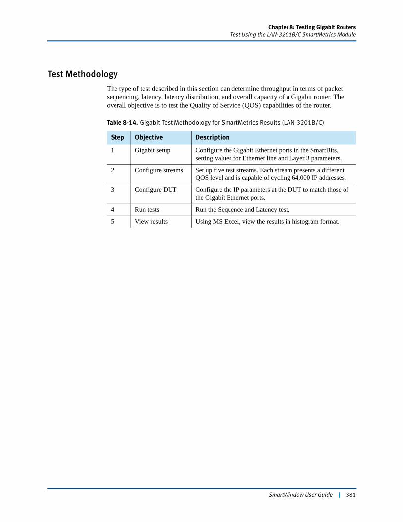
Chapter 8: Testing Gigabit RoutersTest Using the LAN-3201B/C SmartMetrics Module
Test Methodology
The type of test described in this section can determine throughput in terms of packet sequencing, latency, latency distribution, and overall capacity of a Gigabit router. The overall objective is to test the Quality of Service (QOS) capabilities of the router.
Table 8-14. Gigabit Test Methodology for SmartMetrics Results (LAN-3201B/C)
Step Objective Description
1 Gigabit setup Configure the Gigabit Ethernet ports in the SmartBits, setting values for Ethernet line and Layer 3 parameters.
2 Configure streams Set up five test streams. Each stream presents a different QOS level and is capable of cycling 64,000 IP addresses.
3 Configure DUT Configure the IP parameters at the DUT to match those of the Gigabit Ethernet ports.
4 Run tests Run the Sequence and Latency test.
5 View results Using MS Excel, view the results in histogram format.
SmartWindow User Guide | 381
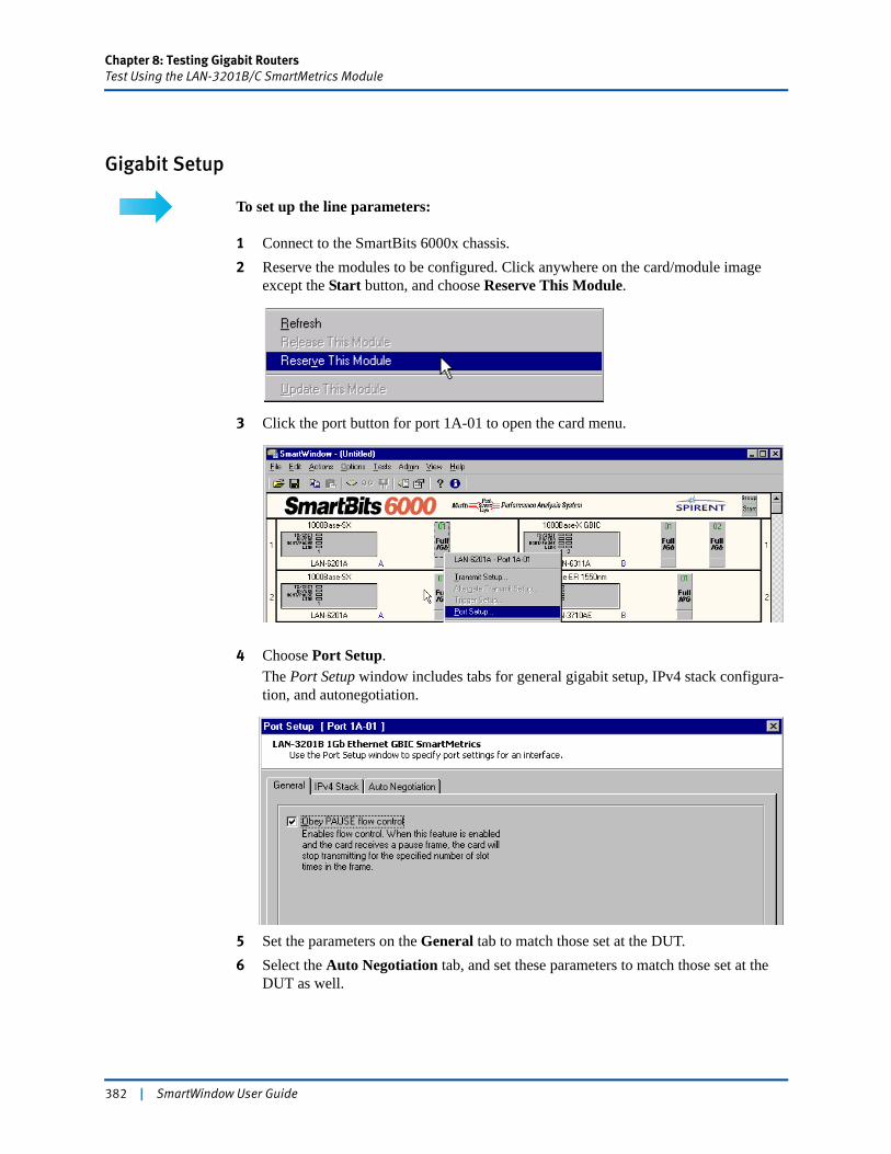
Chapter 8: Testing Gigabit RoutersTest Using the LAN-3201B/C SmartMetrics Module
Gigabit Setup
To set up the line parameters:
1 Connect to the SmartBits 6000x chassis.2 Reserve the modules to be configured. Click anywhere on the card/module image
except the Start button, and choose Reserve This Module.
3 Click the port button for port 1A-01 to open the card menu.
4 Choose Port Setup.The Port Setup window includes tabs for general gigabit setup, IPv4 stack configura-tion, and autonegotiation.
5 Set the parameters on the General tab to match those set at the DUT.6 Select the Auto Negotiation tab, and set these parameters to match those set at the
DUT as well.
382 | SmartWindow User Guide
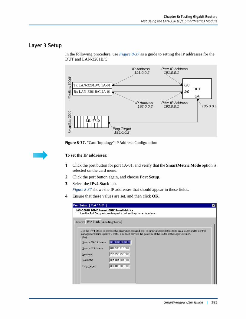
Chapter 8: Testing Gigabit RoutersTest Using the LAN-3201B/C SmartMetrics Module
Layer 3 Setup
In the following procedure, use Figure 8-37 as a guide to setting the IP addresses for the DUT and LAN-3201B/C.
Figure 8-37. “Card Topology” IP Address Configuration
To set the IP addresses:
1 Click the port button for port 1A-01, and verify that the SmartMetric Mode option is selected on the card menu.
2 Click the port button again, and choose Port Setup.3 Select the IPv4 Stack tab.
Figure 8-37 shows the IP addresses that should appear in these fields.4 Ensure that these values are set, and then click OK.
Smar
tBits
600
0BSm
artB
its 2
000
Tx LAN-3201B/C 1A-01
ML-7710
DUT
IP Address
Peer IP Address
Ping Target
191.0.0.2
192.0.0.1
195.0.0.2
Rx LAN-3201B/C 2A-01
IP Address192.0.0.2
Peer IP Address191.0.0.1
0/0
1/02/0
195.0.0.1
SmartWindow User Guide | 383

Chapter 8: Testing Gigabit RoutersTest Using the LAN-3201B/C SmartMetrics Module
Configure Streams on the Transmitting Card
Now configure the test streams. It is possible to configure 2,000 streams, but it generally is not necessary to configure that many. When measuring the QOS capability of a router, it is better to create only enough streams to simulate each type of service.
Example: If there are five levels of service, one stream for each level can be created, for a total of five streams. Because each stream can generate 64,000 individually configurable flows—the equivalent to 320,000 flows per port—the LAN-3201B/C card creates a test case that is more manageable and useful than creating many hard to manage streams.
To set up streams:
Set up streams on the Tx card.
1 From the main menu, click the card to be configured.2 Choose Transmit Setup.
The following window appears.
As streams are created, SmartWindow calculates the individual and total frame rates for the specified card. (See Table 8-15, “SmartMetrics Gigabit Frame Rates Defined,” on page 385.)
Displays the requested and calculated frames rates and percentages for individual streams.
Displays the total calculated frame rates and percentages for all streams.
384 | SmartWindow User Guide
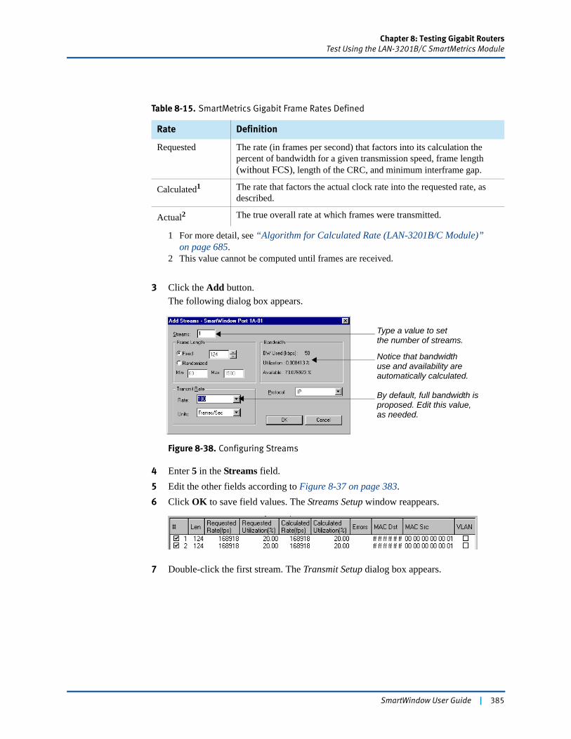
Chapter 8: Testing Gigabit RoutersTest Using the LAN-3201B/C SmartMetrics Module
3 Click the Add button.The following dialog box appears.
Figure 8-38. Configuring Streams
4 Enter 5 in the Streams field.5 Edit the other fields according to Figure 8-37 on page 383. 6 Click OK to save field values. The Streams Setup window reappears.
7 Double-click the first stream. The Transmit Setup dialog box appears.
Table 8-15. SmartMetrics Gigabit Frame Rates Defined
Rate Definition
Requested The rate (in frames per second) that factors into its calculation the percent of bandwidth for a given transmission speed, frame length (without FCS), length of the CRC, and minimum interframe gap.
Calculated1
1 For more detail, see “Algorithm for Calculated Rate (LAN-3201B/C Module)” on page 685.
The rate that factors the actual clock rate into the requested rate, as described.
Actual2
2 This value cannot be computed until frames are received.
The true overall rate at which frames were transmitted.
Type a value to setthe number of streams.
Notice that bandwidthuse and availability are automatically calculated.
By default, full bandwidth isproposed. Edit this value,as needed.
SmartWindow User Guide | 385
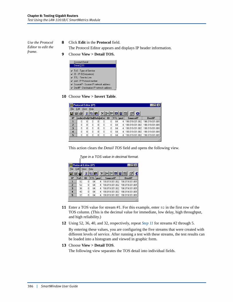
Chapter 8: Testing Gigabit RoutersTest Using the LAN-3201B/C SmartMetrics Module
Use the Protocol Editor to edit the frame.
8 Click Edit in the Protocol field.The Protocol Editor appears and displays IP header information.
9 Choose View > Detail TOS.
10 Choose View > Invert Table.
This action clears the Detail TOS field and opens the following view.
11 Enter a TOS value for stream #1. For this example, enter 92 in the first row of the TOS column. (This is the decimal value for immediate, low delay, high throughput, and high reliability.)
12 Using 52, 36, 40, and 32, respectively, repeat Step 11 for streams #2 through 5.By entering these values, you are configuring the five streams that were created with different levels of service. After running a test with these streams, the test results can be loaded into a histogram and viewed in graphic form.
13 Choose View > Detail TOS.The following view separates the TOS detail into individual fields.
Type in a TOS value in decimal format.
386 | SmartWindow User Guide
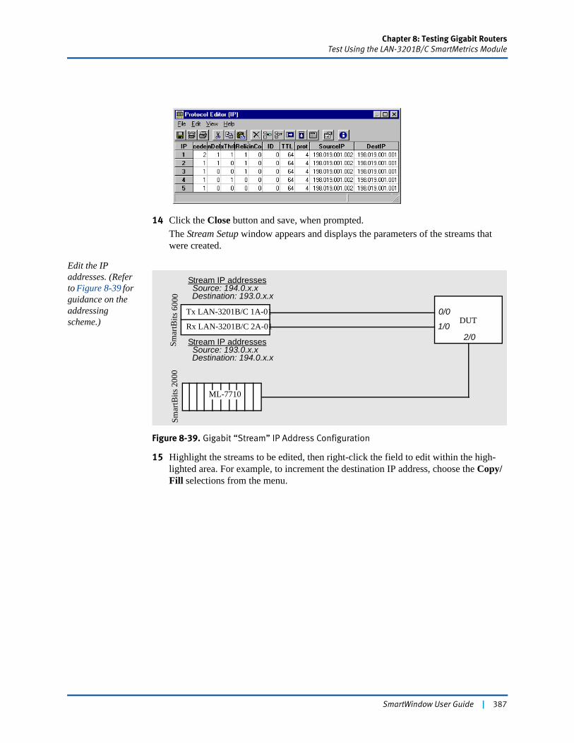
Chapter 8: Testing Gigabit RoutersTest Using the LAN-3201B/C SmartMetrics Module
14 Click the Close button and save, when prompted.The Stream Setup window appears and displays the parameters of the streams that were created.
Edit the IP addresses. (Refer to Figure 8-39 for guidance on the addressing scheme.)
Figure 8-39. Gigabit “Stream” IP Address Configuration
15 Highlight the streams to be edited, then right-click the field to edit within the high-lighted area. For example, to increment the destination IP address, choose the Copy/Fill selections from the menu.
Smar
tBits
600
0Sm
artB
its 2
000
Tx LAN-3201B/C 1A-01
ML-7710
DUTRx LAN-3201B/C 2A-01
Stream IP addressesSource: 194.0.x.xDestination: 193.0.x.x
Stream IP addressesSource: 193.0.x.xDestination: 194.0.x.x
0/0
1/02/0
SmartWindow User Guide | 387
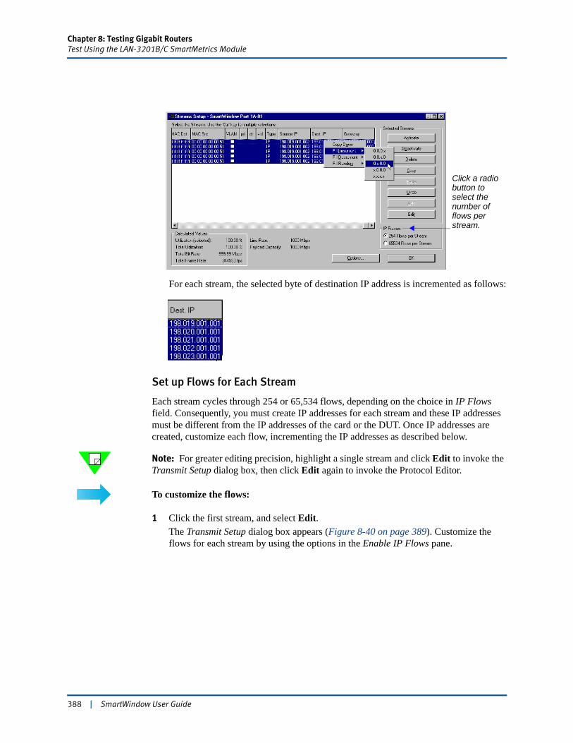
Chapter 8: Testing Gigabit RoutersTest Using the LAN-3201B/C SmartMetrics Module
For each stream, the selected byte of destination IP address is incremented as follows:
Set up Flows for Each Stream
Each stream cycles through 254 or 65,534 flows, depending on the choice in IP Flows field. Consequently, you must create IP addresses for each stream and these IP addresses must be different from the IP addresses of the card or the DUT. Once IP addresses are created, customize each flow, incrementing the IP addresses as described below.
Note: For greater editing precision, highlight a single stream and click Edit to invoke the Transmit Setup dialog box, then click Edit again to invoke the Protocol Editor.
To customize the flows:
1 Click the first stream, and select Edit.The Transmit Setup dialog box appears (Figure 8-40 on page 389). Customize the flows for each stream by using the options in the Enable IP Flows pane.
Click a radio button to select the number of flows per stream.
388 | SmartWindow User Guide
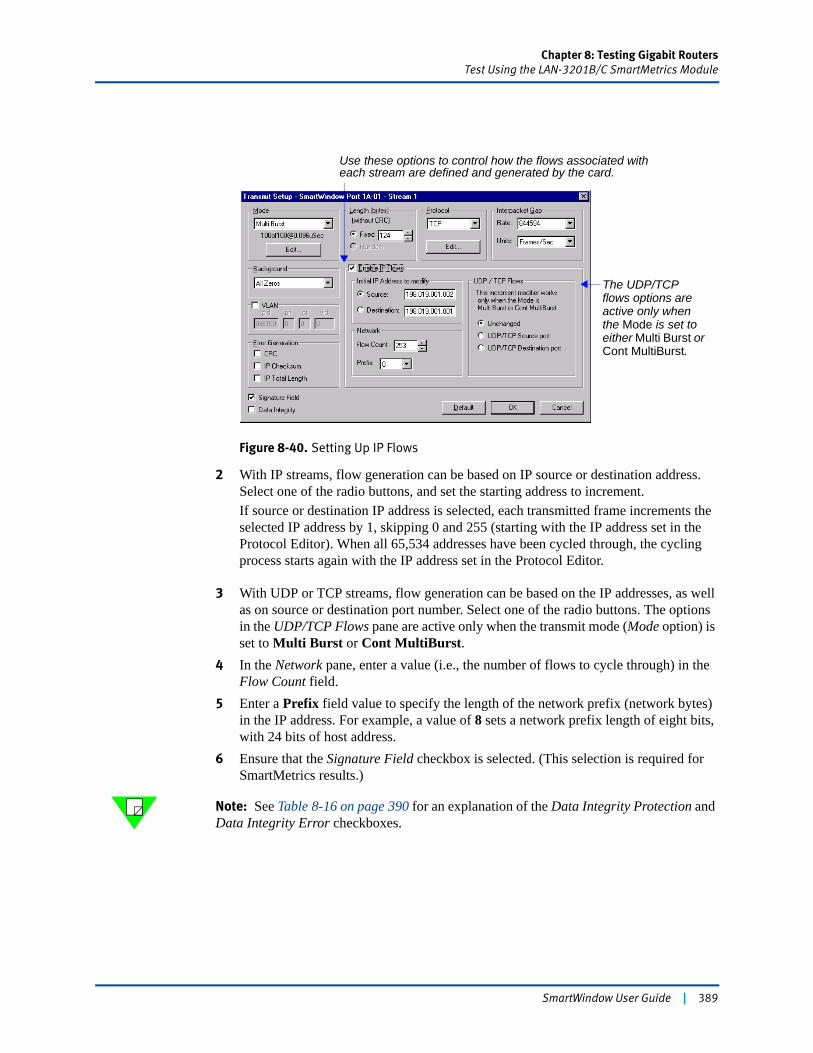
Chapter 8: Testing Gigabit RoutersTest Using the LAN-3201B/C SmartMetrics Module
Figure 8-40. Setting Up IP Flows
2 With IP streams, flow generation can be based on IP source or destination address. Select one of the radio buttons, and set the starting address to increment.If source or destination IP address is selected, each transmitted frame increments the selected IP address by 1, skipping 0 and 255 (starting with the IP address set in the Protocol Editor). When all 65,534 addresses have been cycled through, the cycling process starts again with the IP address set in the Protocol Editor.
3 With UDP or TCP streams, flow generation can be based on the IP addresses, as well as on source or destination port number. Select one of the radio buttons. The options in the UDP/TCP Flows pane are active only when the transmit mode (Mode option) is set to Multi Burst or Cont MultiBurst.
4 In the Network pane, enter a value (i.e., the number of flows to cycle through) in the Flow Count field.
5 Enter a Prefix field value to specify the length of the network prefix (network bytes) in the IP address. For example, a value of 8 sets a network prefix length of eight bits, with 24 bits of host address.
6 Ensure that the Signature Field checkbox is selected. (This selection is required for SmartMetrics results.)
Note: See Table 8-16 on page 390 for an explanation of the Data Integrity Protection and Data Integrity Error checkboxes.
Use these options to control how the flows associated with each stream are defined and generated by the card.
The UDP/TCP flows options are active only when the Mode is set to either Multi Burst or Cont MultiBurst.
SmartWindow User Guide | 389
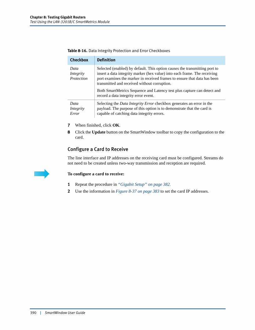
Chapter 8: Testing Gigabit RoutersTest Using the LAN-3201B/C SmartMetrics Module
7 When finished, click OK.8 Click the Update button on the SmartWindow toolbar to copy the configuration to the
card.
Configure a Card to Receive
The line interface and IP addresses on the receiving card must be configured. Streams do not need to be created unless two-way transmission and reception are required.
To configure a card to receive:
1 Repeat the procedure in “Gigabit Setup” on page 382.2 Use the information in Figure 8-37 on page 383 to set the card IP addresses.
Table 8-16. Data Integrity Protection and Error Checkboxes
Checkbox Definition
Data Integrity Protection
Selected (enabled) by default. This option causes the transmitting port to insert a data integrity marker (hex value) into each frame. The receiving port examines the marker in received frames to ensure that data has been transmitted and received without corruption.
Both SmartMetrics Sequence and Latency test plus capture can detect and record a data integrity error event.
Data Integrity Error
Selecting the Data Integrity Error checkbox generates an error in the payload. The purpose of this option is to demonstrate that the card is capable of catching data integrity errors.
390 | SmartWindow User Guide

Chapter 8: Testing Gigabit RoutersTest Using the LAN-3201B/C SmartMetrics Module
Set up the DUT
Refer to “Configuring the DUT” on page 413 for a description of how to set up the DUT.
Send Traffic and View CountersNow you are ready to transmit traffic and view counters. Proceed to “Configuring SmartCounters” on page 415 and “Running SmartCounters” on page 435 for steps.
SmartWindow User Guide | 391
Chapter 8: Testing Gigabit RoutersConfiguring Transmit Streams on TeraMetrics Modules
Configuring Transmit Streams on TeraMetrics ModulesThe TeraMetrics modules have a unique set of windows and menus that provide templates to easily configure streams that use IPv4, IPv6, and other protocols. These configuration techniques are identical for all TeraMetrics modules; however, there may be subtle differences in the layout of the screens. The following example uses a XLW-3731A.
Each stream can generate a large number of individual flows. A test setup with the minimum number of streams and ample flow generation can be more manageable and useful than one involving many streams.
The number of available streams depends on the stream header length. IPv6 streams require a header length of 128 bytes (without FCS). This global setting for the port results in a total stream count of 512, even if IPv4 streams are also configured on the same port. (See “Set the Stream Header Length”.)
Note: The sample test bed configurations used in this section are designed to explain specific network design principles. These configurations are not necessarily intended to be used in your test beds because of the unique characteristics of each test configuration. Instead, they provide reference points for understanding the different types of stream configurations.
Set the Stream Header Length
To set the length:
1 Click the port button on the card image, and choose Transmit Setup.The Streams Setup window opens. (See Figure 8-41 on page 393.)
2 In the Stream Header Length pane, click the 128-byte [Max 512 Streams] (without FCS) button. Now define the schedule mode for the port, using the guidelines starting with “Defin-ing the Schedule Mode” on page 393.
Note: The LAN-3311A TeraMetrics module does not contain the advanced scheduler mode.
392 | SmartWindow User Guide
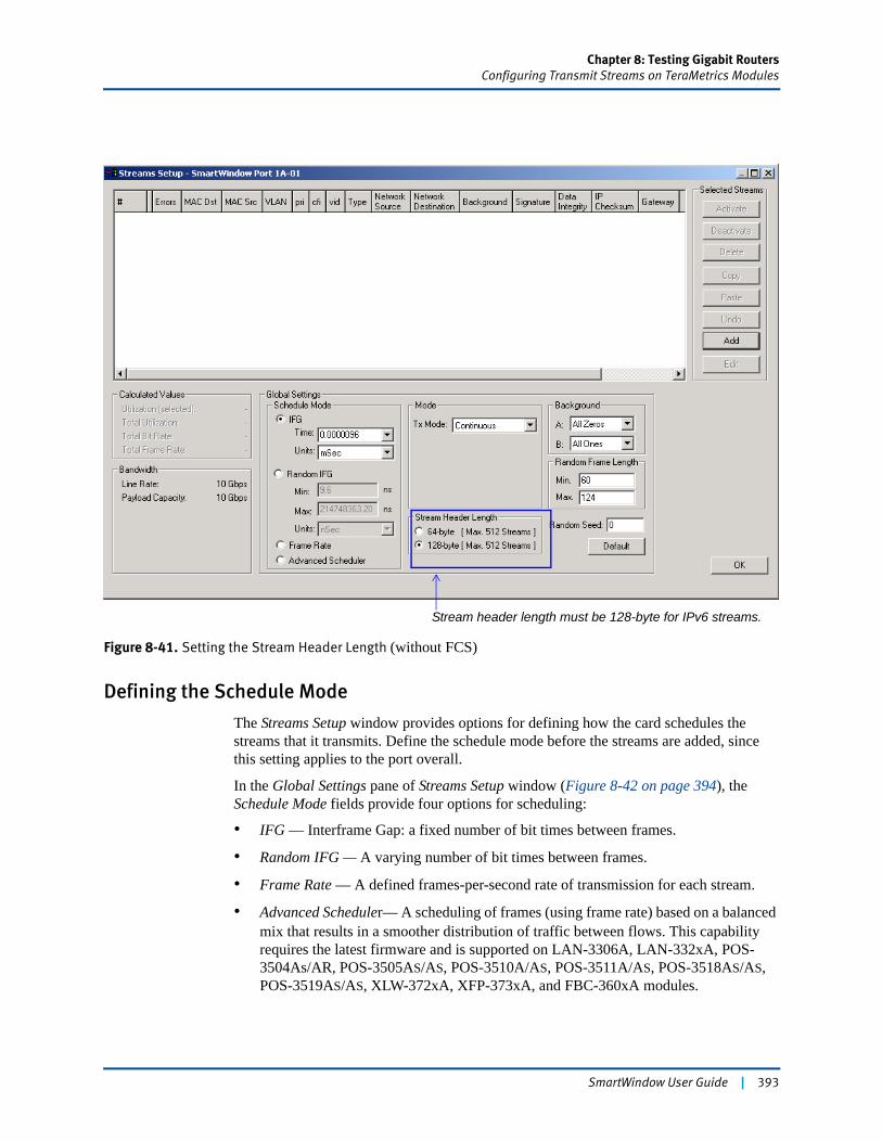
Chapter 8: Testing Gigabit RoutersConfiguring Transmit Streams on TeraMetrics Modules
Figure 8-41. Setting the Stream Header Length (without FCS)
Defining the Schedule Mode
The Streams Setup window provides options for defining how the card schedules the streams that it transmits. Define the schedule mode before the streams are added, since this setting applies to the port overall.
In the Global Settings pane of Streams Setup window (Figure 8-42 on page 394), the Schedule Mode fields provide four options for scheduling:
• IFG — Interframe Gap: a fixed number of bit times between frames.
• Random IFG — A varying number of bit times between frames.
• Frame Rate — A defined frames-per-second rate of transmission for each stream.
• Advanced Scheduler— A scheduling of frames (using frame rate) based on a balanced mix that results in a smoother distribution of traffic between flows. This capability requires the latest firmware and is supported on LAN-3306A, LAN-332xA, POS-3504As/AR, POS-3505AS/AS, POS-3510A/AS, POS-3511A/AS, POS-3518AS/AS, POS-3519AS/AS, XLW-372xA, XFP-373xA, and FBC-360xA modules.
Stream header length must be 128-byte for IPv6 streams.
SmartWindow User Guide | 393
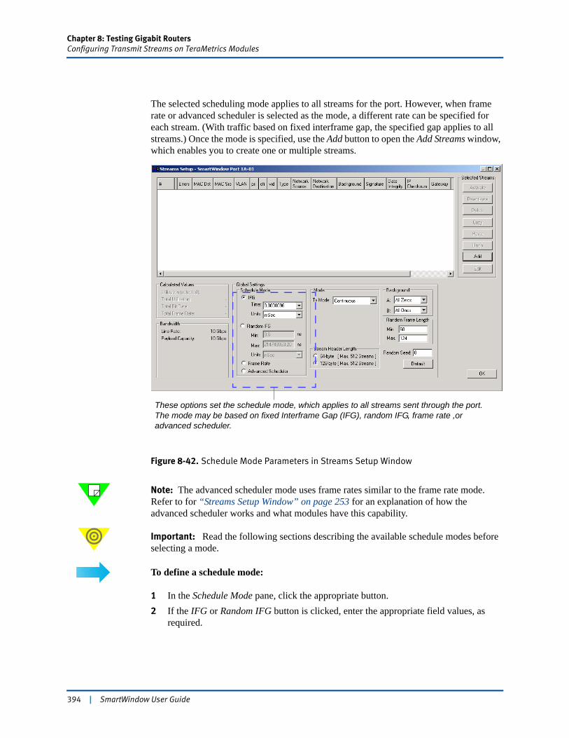
Chapter 8: Testing Gigabit RoutersConfiguring Transmit Streams on TeraMetrics Modules
The selected scheduling mode applies to all streams for the port. However, when frame rate or advanced scheduler is selected as the mode, a different rate can be specified for each stream. (With traffic based on fixed interframe gap, the specified gap applies to all streams.) Once the mode is specified, use the Add button to open the Add Streams window, which enables you to create one or multiple streams.
Figure 8-42. Schedule Mode Parameters in Streams Setup Window
Note: The advanced scheduler mode uses frame rates similar to the frame rate mode. Refer to for “Streams Setup Window” on page 253 for an explanation of how the advanced scheduler works and what modules have this capability.
Important: Read the following sections describing the available schedule modes before selecting a mode.
To define a schedule mode:
1 In the Schedule Mode pane, click the appropriate button.2 If the IFG or Random IFG button is clicked, enter the appropriate field values, as
required.
These options set the schedule mode, which applies to all streams sent through the port. The mode may be based on fixed Interframe Gap (IFG), random IFG, frame rate ,or advanced scheduler.
394 | SmartWindow User Guide
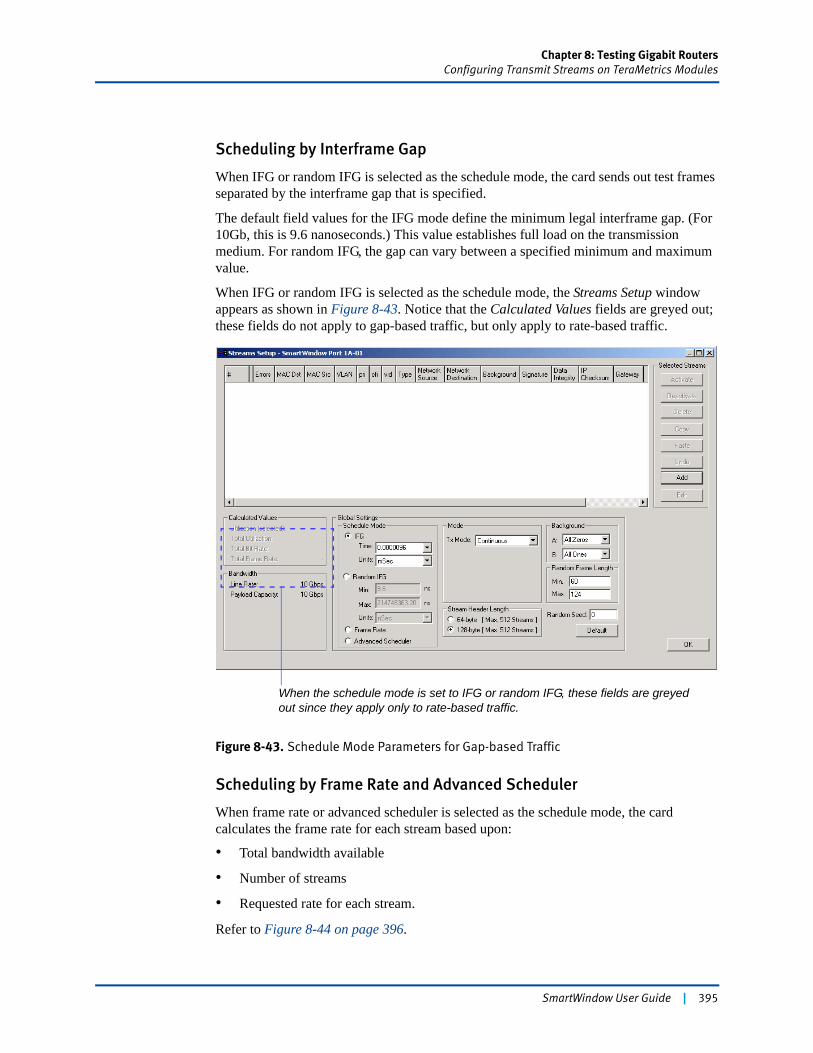
Chapter 8: Testing Gigabit RoutersConfiguring Transmit Streams on TeraMetrics Modules
Scheduling by Interframe Gap
When IFG or random IFG is selected as the schedule mode, the card sends out test frames separated by the interframe gap that is specified.
The default field values for the IFG mode define the minimum legal interframe gap. (For 10Gb, this is 9.6 nanoseconds.) This value establishes full load on the transmission medium. For random IFG, the gap can vary between a specified minimum and maximum value.
When IFG or random IFG is selected as the schedule mode, the Streams Setup window appears as shown in Figure 8-43. Notice that the Calculated Values fields are greyed out; these fields do not apply to gap-based traffic, but only apply to rate-based traffic.
Figure 8-43. Schedule Mode Parameters for Gap-based Traffic
Scheduling by Frame Rate and Advanced Scheduler
When frame rate or advanced scheduler is selected as the schedule mode, the card calculates the frame rate for each stream based upon:
• Total bandwidth available
• Number of streams
• Requested rate for each stream.
Refer to Figure 8-44 on page 396.
When the schedule mode is set to IFG or random IFG, these fields are greyed out since they apply only to rate-based traffic.
SmartWindow User Guide | 395
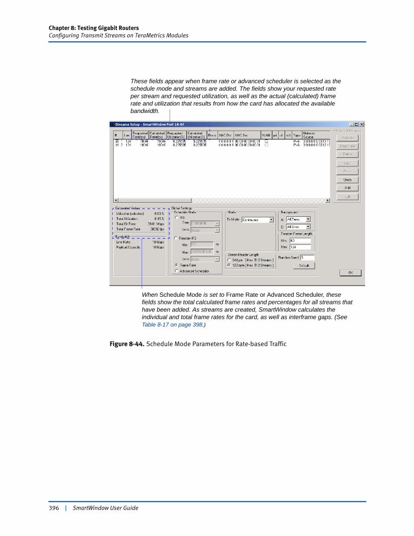
Chapter 8: Testing Gigabit RoutersConfiguring Transmit Streams on TeraMetrics Modules
Figure 8-44. Schedule Mode Parameters for Rate-based Traffic
When Schedule Mode is set to Frame Rate or Advanced Scheduler, these fields show the total calculated frame rates and percentages for all streams that have been added. As streams are created, SmartWindow calculates the individual and total frame rates for the card, as well as interframe gaps. (See Table 8-17 on page 398.)
These fields appear when frame rate or advanced scheduler is selected as the schedule mode and streams are added. The fields show your requested rate per stream and requested utilization, as well as the actual (calculated) frame rate and utilization that results from how the card has allocated the available bandwidth.
396 | SmartWindow User Guide
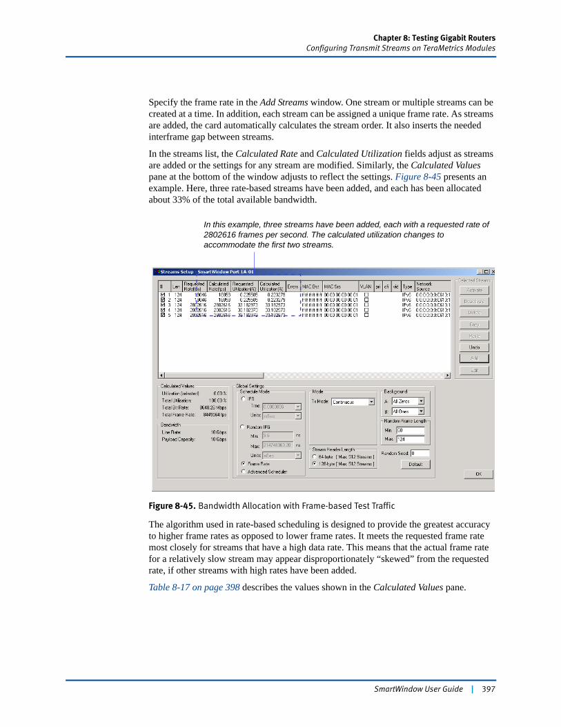
Chapter 8: Testing Gigabit RoutersConfiguring Transmit Streams on TeraMetrics Modules
Specify the frame rate in the Add Streams window. One stream or multiple streams can be created at a time. In addition, each stream can be assigned a unique frame rate. As streams are added, the card automatically calculates the stream order. It also inserts the needed interframe gap between streams.
In the streams list, the Calculated Rate and Calculated Utilization fields adjust as streams are added or the settings for any stream are modified. Similarly, the Calculated Values pane at the bottom of the window adjusts to reflect the settings. Figure 8-45 presents an example. Here, three rate-based streams have been added, and each has been allocated about 33% of the total available bandwidth.
Figure 8-45. Bandwidth Allocation with Frame-based Test Traffic
The algorithm used in rate-based scheduling is designed to provide the greatest accuracy to higher frame rates as opposed to lower frame rates. It meets the requested frame rate most closely for streams that have a high data rate. This means that the actual frame rate for a relatively slow stream may appear disproportionately “skewed” from the requested rate, if other streams with high rates have been added.
Table 8-17 on page 398 describes the values shown in the Calculated Values pane.
In this example, three streams have been added, each with a requested rate of 2802616 frames per second. The calculated utilization changes to accommodate the first two streams.
SmartWindow User Guide | 397
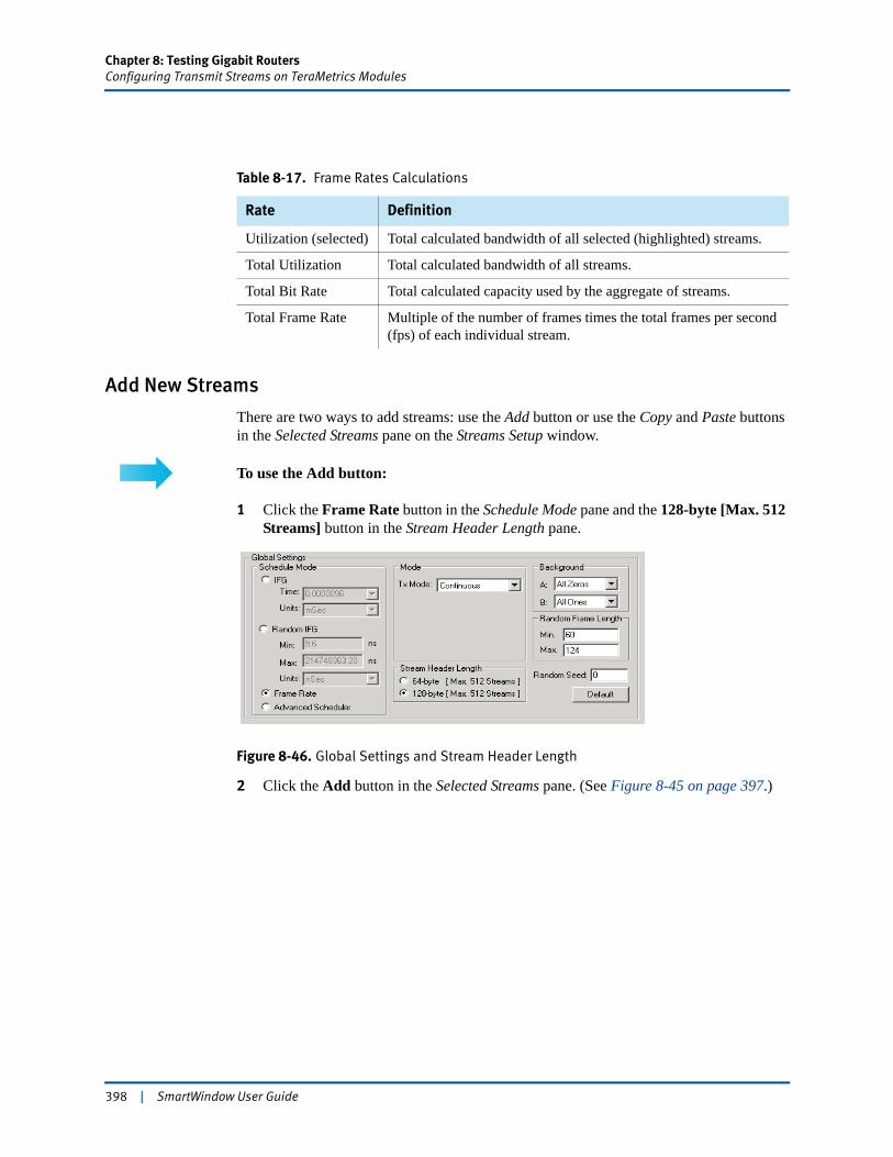
Chapter 8: Testing Gigabit RoutersConfiguring Transmit Streams on TeraMetrics Modules
Add New Streams
There are two ways to add streams: use the Add button or use the Copy and Paste buttons in the Selected Streams pane on the Streams Setup window.
To use the Add button:
1 Click the Frame Rate button in the Schedule Mode pane and the 128-byte [Max. 512 Streams] button in the Stream Header Length pane.
Figure 8-46. Global Settings and Stream Header Length
2 Click the Add button in the Selected Streams pane. (See Figure 8-45 on page 397.)
Table 8-17. Frame Rates Calculations
Rate Definition
Utilization (selected) Total calculated bandwidth of all selected (highlighted) streams.
Total Utilization Total calculated bandwidth of all streams.
Total Bit Rate Total calculated capacity used by the aggregate of streams.
Total Frame Rate Multiple of the number of frames times the total frames per second (fps) of each individual stream.
398 | SmartWindow User Guide
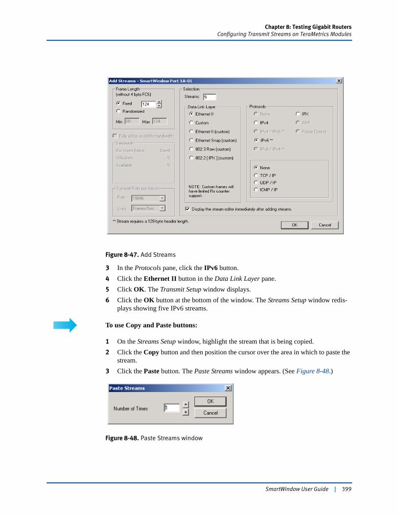
Chapter 8: Testing Gigabit RoutersConfiguring Transmit Streams on TeraMetrics Modules
Figure 8-47. Add Streams
3 In the Protocols pane, click the IPv6 button. 4 Click the Ethernet II button in the Data Link Layer pane. 5 Click OK. The Transmit Setup window displays.6 Click the OK button at the bottom of the window. The Streams Setup window redis-
plays showing five IPv6 streams.
To use Copy and Paste buttons:
1 On the Streams Setup window, highlight the stream that is being copied.2 Click the Copy button and then position the cursor over the area in which to paste the
stream.3 Click the Paste button. The Paste Streams window appears. (See Figure 8-48.)
Figure 8-48. Paste Streams window
SmartWindow User Guide | 399
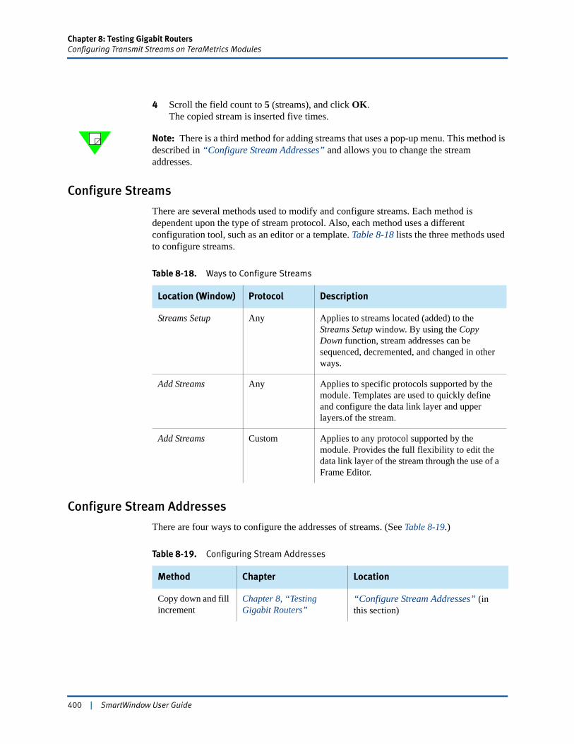
Chapter 8: Testing Gigabit RoutersConfiguring Transmit Streams on TeraMetrics Modules
4 Scroll the field count to 5 (streams), and click OK.The copied stream is inserted five times.
Note: There is a third method for adding streams that uses a pop-up menu. This method is described in “Configure Stream Addresses” and allows you to change the stream addresses.
Configure Streams
There are several methods used to modify and configure streams. Each method is dependent upon the type of stream protocol. Also, each method uses a different configuration tool, such as an editor or a template. Table 8-18 lists the three methods used to configure streams.
Configure Stream Addresses
There are four ways to configure the addresses of streams. (See Table 8-19.)
Table 8-18. Ways to Configure Streams
Location (Window) Protocol Description
Streams Setup Any Applies to streams located (added) to the Streams Setup window. By using the Copy Down function, stream addresses can be sequenced, decremented, and changed in other ways.
Add Streams Any Applies to specific protocols supported by the module. Templates are used to quickly define and configure the data link layer and upper layers.of the stream.
Add Streams Custom Applies to any protocol supported by the module. Provides the full flexibility to edit the data link layer of the stream through the use of a Frame Editor.
Table 8-19. Configuring Stream Addresses
Method Chapter Location
Copy down and fill increment
Chapter 8, “Testing Gigabit Routers”
“Configure Stream Addresses” (in this section)
400 | SmartWindow User Guide
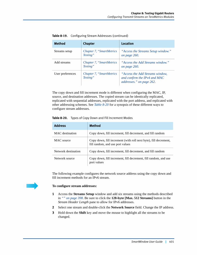
Chapter 8: Testing Gigabit RoutersConfiguring Transmit Streams on TeraMetrics Modules
The copy down and fill increment mode is different when configuring the MAC, IP, source, and destination addresses. The copied stream can be identically replicated, replicated with sequential addresses, replicated with the port address, and replicated with other addressing schemes. See Table 8-20 for a synopsis of these different ways to configure stream addresses.
The following example configures the network source address using the copy down and fill increment methods for an IPv6 stream.
To configure stream addresses:
1 Access the Streams Setup window and add six streams using the methods described in “” on page 398. Be sure to click the 128-byte [Max. 512 Streams] button in the Stream Header Length pane to allow for IPv6 addresses.
2 Select one stream and double-click the Network Source field. Change the IP address.3 Hold down the Shift key and move the mouse to highlight all the streams to be
changed.
Streams setup Chapter 7, “SmartMetrics Testing”
“Access the Streams Setup window.” on page 260.
Add streams Chapter 7, “SmartMetrics Testing”
“Access the Add Streams window.” on page 260.
User preferences Chapter 7, “SmartMetrics Testing”
“Access the Add Streams window, and confirm the IPv4 and MAC addresses.” on page 262.
Table 8-20. Types of Copy Down and Fill Increment Modes
Address Method
MAC destination Copy down, fill increment, fill decrement, and fill random
MAC source Copy down, fill increment (with roll next byte), fill decrement, fill random, and use port values
Network destination Copy down, fill increment, fill decrement, and fill random
Network source Copy down, fill increment, fill decrement, fill random, and use port values
Table 8-19. Configuring Stream Addresses (continued)
Method Chapter Location
SmartWindow User Guide | 401
Chapter 8: Testing Gigabit RoutersConfiguring Transmit Streams on TeraMetrics Modules
Note: This copy function is available for streams that use the same protocol. Therefore when selecting the streams to be configured, be sure those streams use the protocol that the primary (copied) stream is using4 Right-click the Network Source field, and choose Copy Down from the pop-up
menu.5 The IP address is duplicated for all streams. 6 Right-click the Network Source field again and choose Fill Increment >
0.0.0.0.0.0.0.0.0.0.0.x.0.0.0.0.0. The selected byte in the IP address (x) is incremented with each successive stream.
Figure 8-49. Using Copy Down and Fill Increment
Use the Add Streams Window to Configure Streams
The Add Streams window was briefly described and used in the paragraph “Add New Streams” on page 398. This window provides many additional capabilities such as changing the network and data link addresses, adding streams, configuring the data link layer, and configuring Layer 3 and Layer 4. This section gives a brief overview of how to configure Layer 2 and Layer 3.
For information on the other aspects of the Add Streams window, see Chapter 7, “SmartMetrics Testing.”
The Add Streams window has four window panes: Frame Length, Bandwidth, Transmit Rate per Stream, and Selection. The Selection pane contains an additional two panes. (See Figure 8-50 on page 403 for an illustration of the Add Streams window.)
402 | SmartWindow User Guide
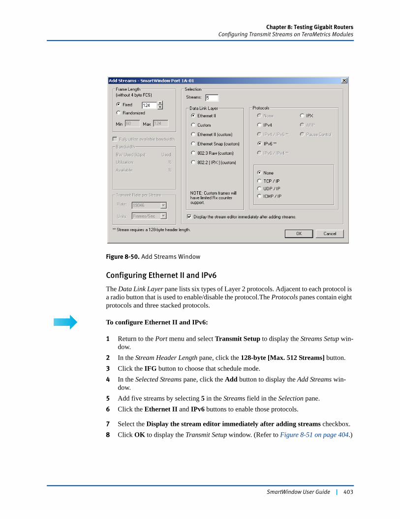
Chapter 8: Testing Gigabit RoutersConfiguring Transmit Streams on TeraMetrics Modules
Figure 8-50. Add Streams Window
Configuring Ethernet II and IPv6
The Data Link Layer pane lists six types of Layer 2 protocols. Adjacent to each protocol is a radio button that is used to enable/disable the protocol.The Protocols panes contain eight protocols and three stacked protocols.
To configure Ethernet II and IPv6:
1 Return to the Port menu and select Transmit Setup to display the Streams Setup win-dow.
2 In the Stream Header Length pane, click the 128-byte [Max. 512 Streams] button. 3 Click the IFG button to choose that schedule mode.4 In the Selected Streams pane, click the Add button to display the Add Streams win-
dow.5 Add five streams by selecting 5 in the Streams field in the Selection pane.6 Click the Ethernet II and IPv6 buttons to enable those protocols.
7 Select the Display the stream editor immediately after adding streams checkbox.8 Click OK to display the Transmit Setup window. (Refer to Figure 8-51 on page 404.)
SmartWindow User Guide | 403
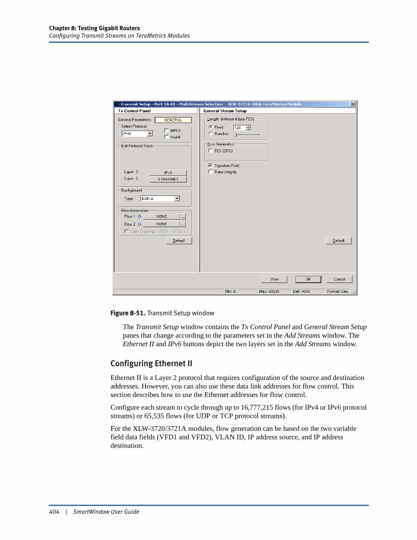
Chapter 8: Testing Gigabit RoutersConfiguring Transmit Streams on TeraMetrics Modules
Figure 8-51. Transmit Setup window
The Transmit Setup window contains the Tx Control Panel and General Stream Setup panes that change according to the parameters set in the Add Streams window. The Ethernet II and IPv6 buttons depict the two layers set in the Add Streams window.
Configuring Ethernet II
Ethernet II is a Layer 2 protocol that requires configuration of the source and destination addresses. However, you can also use these data link addresses for flow control. This section describes how to use the Ethernet addresses for flow control.
Configure each stream to cycle through up to 16,777,215 flows (for IPv4 or IPv6 protocol streams) or 65,535 flows (for UDP or TCP protocol streams).
For the XLW-3720/3721A modules, flow generation can be based on the two variable field data fields (VFD1 and VFD2), VLAN ID, IP address source, and IP address destination.
404 | SmartWindow User Guide
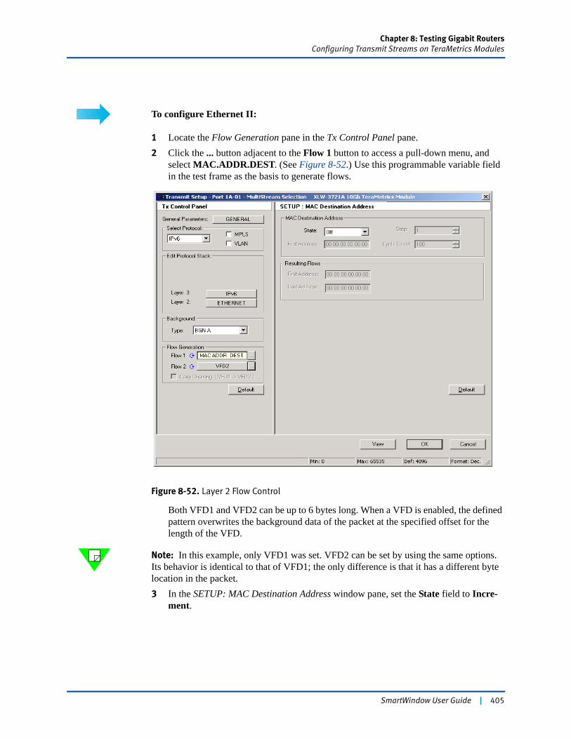
Chapter 8: Testing Gigabit RoutersConfiguring Transmit Streams on TeraMetrics Modules
To configure Ethernet II:
1 Locate the Flow Generation pane in the Tx Control Panel pane.2 Click the ... button adjacent to the Flow 1 button to access a pull-down menu, and
select MAC.ADDR.DEST. (See Figure 8-52.) Use this programmable variable field in the test frame as the basis to generate flows.
Figure 8-52. Layer 2 Flow Control
Both VFD1 and VFD2 can be up to 6 bytes long. When a VFD is enabled, the defined pattern overwrites the background data of the packet at the specified offset for the length of the VFD.
Note: In this example, only VFD1 was set. VFD2 can be set by using the same options. Its behavior is identical to that of VFD1; the only difference is that it has a different byte location in the packet.3 In the SETUP: MAC Destination Address window pane, set the State field to Incre-
ment.
SmartWindow User Guide | 405
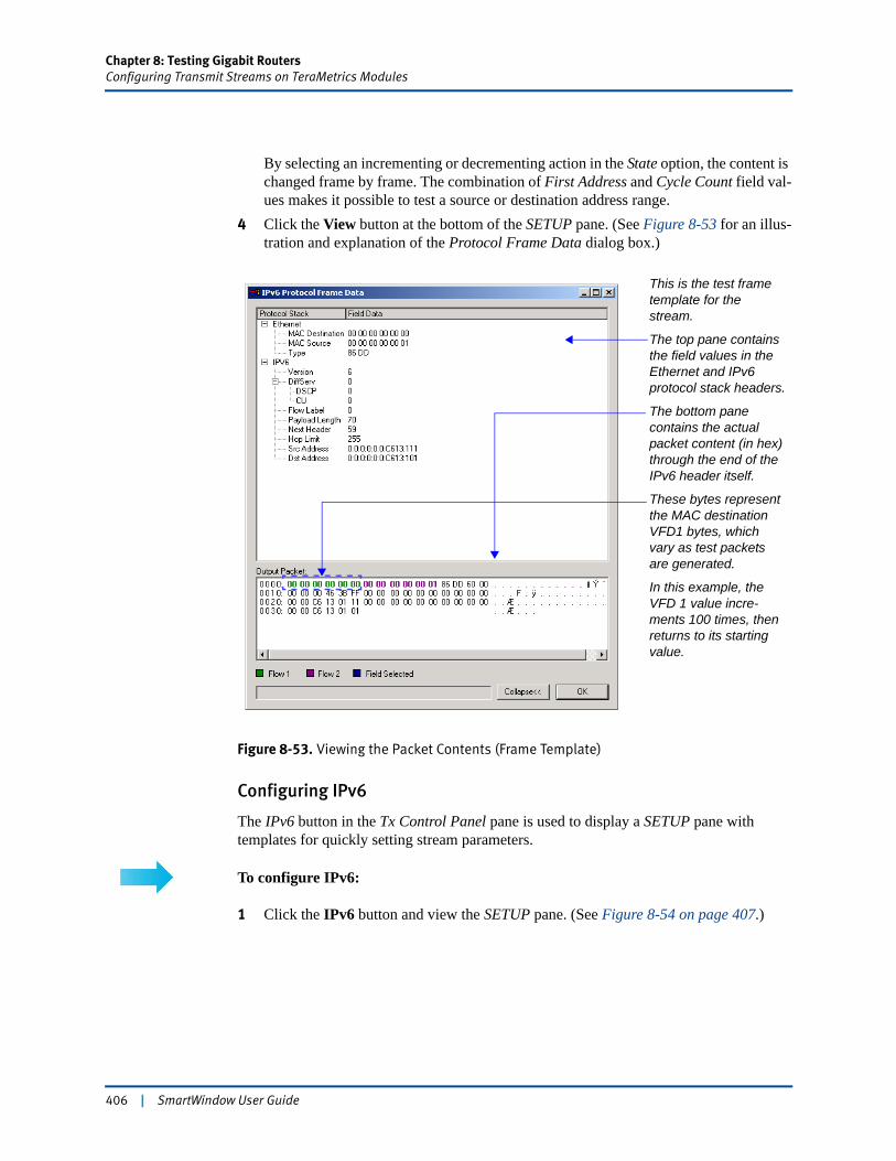
Chapter 8: Testing Gigabit RoutersConfiguring Transmit Streams on TeraMetrics Modules
By selecting an incrementing or decrementing action in the State option, the content is changed frame by frame. The combination of First Address and Cycle Count field val-ues makes it possible to test a source or destination address range.
4 Click the View button at the bottom of the SETUP pane. (See Figure 8-53 for an illus-tration and explanation of the Protocol Frame Data dialog box.)
Figure 8-53. Viewing the Packet Contents (Frame Template)
Configuring IPv6
The IPv6 button in the Tx Control Panel pane is used to display a SETUP pane with templates for quickly setting stream parameters.
To configure IPv6:
1 Click the IPv6 button and view the SETUP pane. (See Figure 8-54 on page 407.)
This is the test frame template for the stream.
The top pane contains the field values in the Ethernet and IPv6 protocol stack headers.
The bottom pane contains the actual packet content (in hex) through the end of the IPv6 header itself.
These bytes represent the MAC destination VFD1 bytes, which vary as test packets are generated.
In this example, the VFD 1 value incre-ments 100 times, then returns to its starting value.
406 | SmartWindow User Guide
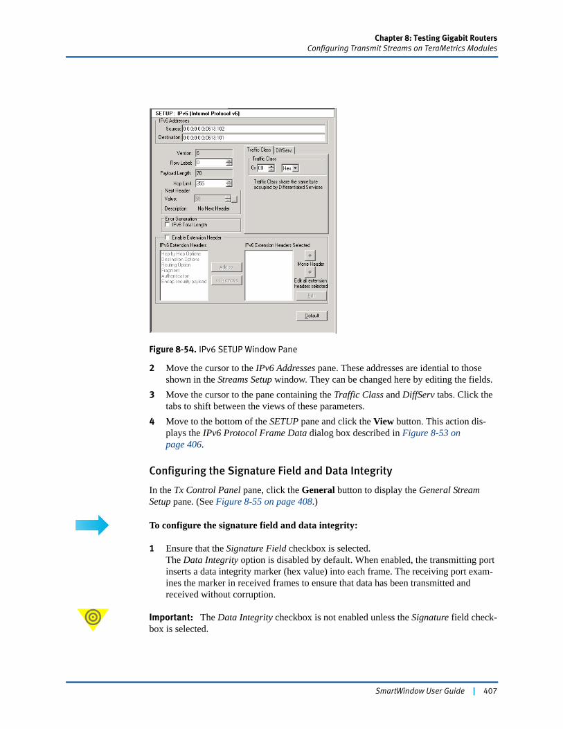
Chapter 8: Testing Gigabit RoutersConfiguring Transmit Streams on TeraMetrics Modules
Figure 8-54. IPv6 SETUP Window Pane
2 Move the cursor to the IPv6 Addresses pane. These addresses are idential to those shown in the Streams Setup window. They can be changed here by editing the fields.
3 Move the cursor to the pane containing the Traffic Class and DiffServ tabs. Click the tabs to shift between the views of these parameters.
4 Move to the bottom of the SETUP pane and click the View button. This action dis-plays the IPv6 Protocol Frame Data dialog box described in Figure 8-53 on page 406.
Configuring the Signature Field and Data Integrity
In the Tx Control Panel pane, click the General button to display the General Stream Setup pane. (See Figure 8-55 on page 408.)
To configure the signature field and data integrity:
1 Ensure that the Signature Field checkbox is selected.The Data Integrity option is disabled by default. When enabled, the transmitting port inserts a data integrity marker (hex value) into each frame. The receiving port exam-ines the marker in received frames to ensure that data has been transmitted and received without corruption.
Important: The Data Integrity checkbox is not enabled unless the Signature field check-box is selected.
SmartWindow User Guide | 407

Chapter 8: Testing Gigabit RoutersConfiguring Transmit Streams on TeraMetrics Modules
Note: The General Stream Setup pane shown in Figure 8-55 has a different design when frame or advanced scheduler mode is used. (In these instances, there are requested and calculated transmit rates.)
Figure 8-55. Signature and Data Integrity Fields
Configuring a Custom Stream
SmartWindow provides the capability to customize a stream with several types of fill fields and other user-defined data through the use of a Frame Editor.
To configure a custom stream:
1 Access the Streams Setup window and highlight an IPv6 stream.2 Click the Edit button to display the Transmit Setup window.3 Access the Select Protocol pane (within the Tx Control Panel pane), and use the pull-
down menu to select Custom.4 Click the Edit button in the SETUP pane to display the Frame Editor. (See
Figure 8-56.)
Figure 8-56. Custom Frame Editor
408 | SmartWindow User Guide
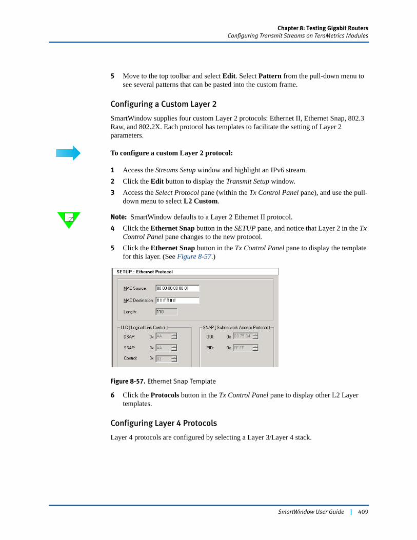
Chapter 8: Testing Gigabit RoutersConfiguring Transmit Streams on TeraMetrics Modules
5 Move to the top toolbar and select Edit. Select Pattern from the pull-down menu to see several patterns that can be pasted into the custom frame.
Configuring a Custom Layer 2
SmartWindow supplies four custom Layer 2 protocols: Ethernet II, Ethernet Snap, 802.3 Raw, and 802.2X. Each protocol has templates to facilitate the setting of Layer 2 parameters.
To configure a custom Layer 2 protocol:
1 Access the Streams Setup window and highlight an IPv6 stream.2 Click the Edit button to display the Transmit Setup window.3 Access the Select Protocol pane (within the Tx Control Panel pane), and use the pull-
down menu to select L2 Custom.
Note: SmartWindow defaults to a Layer 2 Ethernet II protocol. 4 Click the Ethernet Snap button in the SETUP pane, and notice that Layer 2 in the Tx
Control Panel pane changes to the new protocol.5 Click the Ethernet Snap button in the Tx Control Panel pane to display the template
for this layer. (See Figure 8-57.)
Figure 8-57. Ethernet Snap Template
6 Click the Protocols button in the Tx Control Panel pane to display other L2 Layer templates.
Configuring Layer 4 Protocols
Layer 4 protocols are configured by selecting a Layer 3/Layer 4 stack.
SmartWindow User Guide | 409
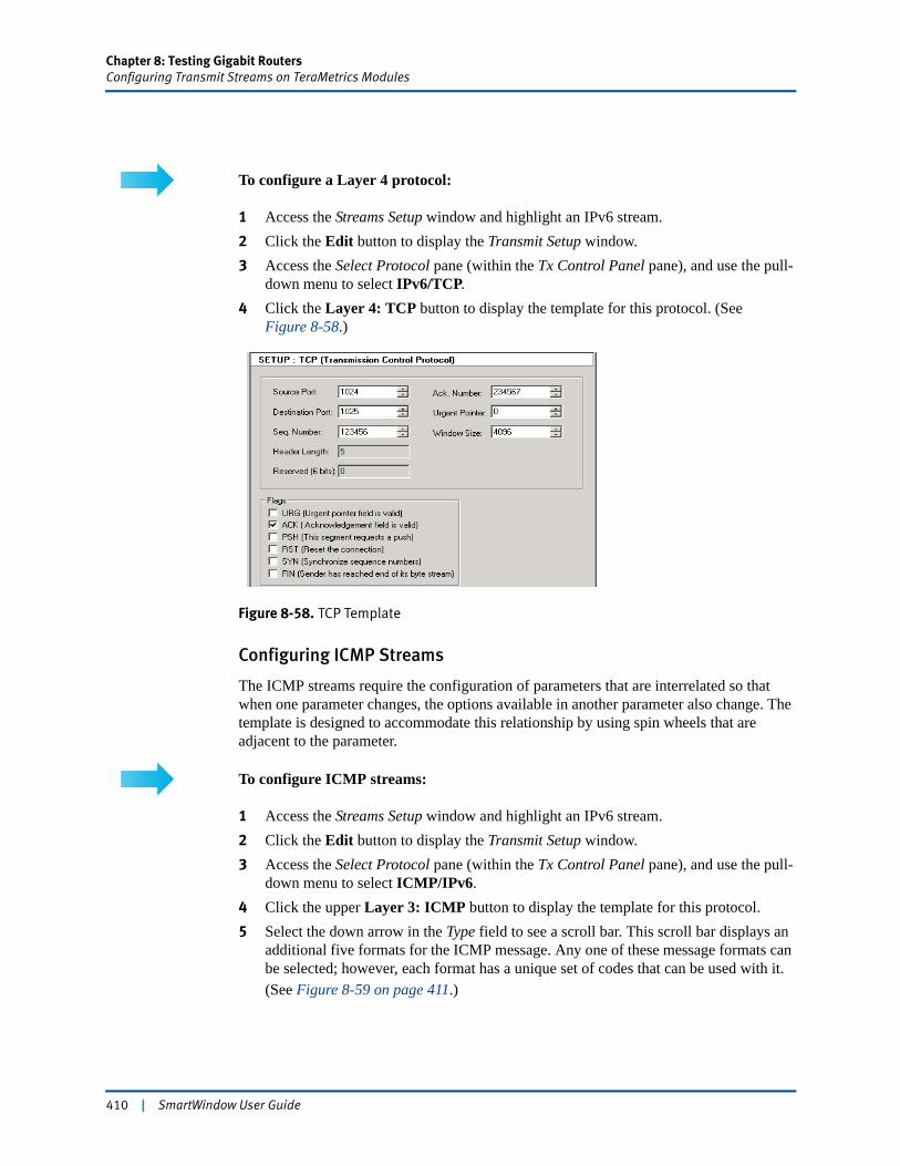
Chapter 8: Testing Gigabit RoutersConfiguring Transmit Streams on TeraMetrics Modules
To configure a Layer 4 protocol:
1 Access the Streams Setup window and highlight an IPv6 stream.2 Click the Edit button to display the Transmit Setup window.3 Access the Select Protocol pane (within the Tx Control Panel pane), and use the pull-
down menu to select IPv6/TCP.4 Click the Layer 4: TCP button to display the template for this protocol. (See
Figure 8-58.)
Figure 8-58. TCP Template
Configuring ICMP Streams
The ICMP streams require the configuration of parameters that are interrelated so that when one parameter changes, the options available in another parameter also change. The template is designed to accommodate this relationship by using spin wheels that are adjacent to the parameter.
To configure ICMP streams:
1 Access the Streams Setup window and highlight an IPv6 stream.2 Click the Edit button to display the Transmit Setup window.3 Access the Select Protocol pane (within the Tx Control Panel pane), and use the pull-
down menu to select ICMP/IPv6.4 Click the upper Layer 3: ICMP button to display the template for this protocol. 5 Select the down arrow in the Type field to see a scroll bar. This scroll bar displays an
additional five formats for the ICMP message. Any one of these message formats can be selected; however, each format has a unique set of codes that can be used with it.(See Figure 8-59 on page 411.)
410 | SmartWindow User Guide
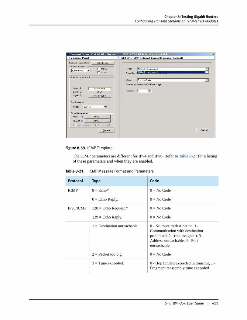
Chapter 8: Testing Gigabit RoutersConfiguring Transmit Streams on TeraMetrics Modules
Figure 8-59. ICMP Template
The ICMP parameters are different for IPv4 and IPv6. Refer to Table 8-21 for a listing of these parameters and when they are enabled.
Table 8-21. ICMP Message Format and Parameters
Protocol Type Code
ICMP 8 = Echo* 0 = No Code
0 = Echo Reply. 0 = No Code
IPv6/ICMP 128 = Echo Request.* 0 = No Code
129 = Echo Reply. 0 = No Code
1 = Destination unreachable. 0 - No route to destination, 1- Communication with destination prohibited, 2 - (not assigned), 3 - Address unreachable, 4 - Port unreachable
2 = Packet too big. 0 = No Code
3 = Time exceeded. 0 - Hop limited exceeded in transmit, 1 - Fragment reassembly time exceeded
SmartWindow User Guide | 411
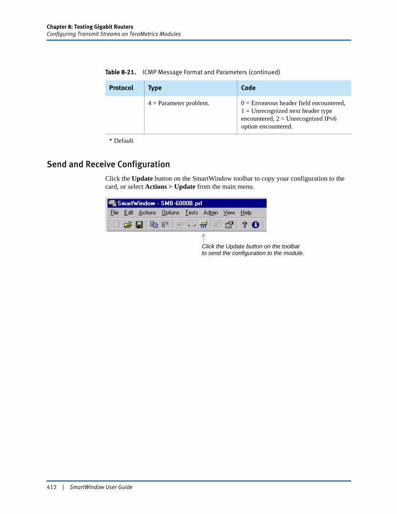
Chapter 8: Testing Gigabit RoutersConfiguring Transmit Streams on TeraMetrics Modules
Send and Receive Configuration
Click the Update button on the SmartWindow toolbar to copy your configuration to the card, or select Actions > Update from the main menu.
4 = Parameter problem. 0 = Erroneous header field encountered, 1 = Unrecognized next header type encountered, 2 = Unrecognized IPv6 option encountered.
* Default
Table 8-21. ICMP Message Format and Parameters (continued)
Protocol Type Code
Click the Update button on the toolbarto send the configuration to the module.
412 | SmartWindow User Guide
Chapter 8: Testing Gigabit RoutersConfiguring the DUT
Configuring the DUTThis section describes how to configure the DUT and/or the SmartBits 600x/6000x chassis that receives the test streams. The test bed design determines how these units are configured.
The receive unit can be the DUT and/or a SmartBits 600x/6000x chassis. The following list gives some sample chassis/DUT test bed configurations:
• One multiport module on the SmartBits 600x/6000x chassis can transmit and receive test packets to/from the DUT.
• Two modules on the SmartBits 600x/6000x chassis can be used separately, where one transmits test packets and the other receives test data from the DUT.
• Two separate chassis can be used where one transmits test packets to the DUT and the other receives test packets from the DUT.
In all these combinations, it is necessary that port addressing be matched to the design of the network. (For the SmartBits 600x/6000x chassis, the procedure to do this is described in “Set Port IP Addresses” on page 414.)
Note: For the DUT, these procedures are located in the DUT installation or user guide.
The type of test traffic is the other aspect of the test bed that impacts the configuration of the receive chassis and DUT. The test traffic can be bi-directional or unidirectional and can come from one chassis or multiple chassis. If the test traffic is bi-directional, with a separate transmit and receive chassis, then it is necessary to configure streams on both units. For:
• XLW-3721A and LAN-331A, refer to “Configuring Transmit Streams on TeraMetrics Modules” on page 392.
• LAN-3710AL/AE/AS, refer to “Test Using the LAN-3710AL/AE/AS 10GbE Module” on page 355.
• LAN-3201B/C, refer to “Test Using the LAN-3201B/C SmartMetrics Module” on page 380.
If the test traffic is unidirectional, then a combination of port configuration and/or stream configuration is required, depending on the movement of test traffic throughout the test bed. Consequently, the traffic generation patterns of the DUT need to match this test design.
Note: Review the profile information of the module to determine the specific SmartBits 600x/6000x chassis interconnection data. (See Figure 8-3 on page 322 for the item description of a XFP-373xa module.)
SmartWindow User Guide | 413
Chapter 8: Testing Gigabit RoutersConfiguring the DUT
Set Port IP Addresses
As indicated in “Configuring the DUT” on page 413, the receive chassis may be a different unit (DUT or SmartBits 600x/600x chassis) than the transmit chassis. In this case and in other test beds, the IP port addressing must be changed to accommodate the new test environment. This is accomplished by using the Port Setup menu. For:
• XLW-3721A and LAN-331A, refer to “Layer 3 Setup: IPv4 Stack and IPv6 Stack” on page 339.
• LAN-3710AL/AE/AS, refer to “Review the Port Setup” on page 356.
• LAN-3311A, refer to “Gigabit Setup” on page 375.
• LAN-3201B/C, refer to “Gigabit Setup” on page 382.
Set DUT Stream IP Addresses
The Gigabit router (DUT) must be able to handle the IP addresses of the streams that were created. Configure the router so that it can build a routing table that knows what to do with each flow. Depending on the router capabilities, this may involve setting up static routes or supernetting, i.e., giving each stream a different second byte, such as 198.19.x.x, 198.20.x.x, 198.21.x.x, etc. This way, as the streams cycle through the frames of a flow, no frames are discarded or lost, and each stream is treated separately in SmartMetrics.
414 | SmartWindow User Guide
Chapter 8: Testing Gigabit RoutersConfiguring SmartCounters
Configuring SmartCountersSmartWindow has two types of SmartCounters with spreadsheet capabilities. Each of these counters is available on one set of modules/cards with a specific hardware chassis. Refer to Table 8-22 for a listing of these combinations and the associated counter title.
Chapter 5, “Advanced Operational Theory” describes the SmartCounters for cards used on the SmartBits 200/2000 chassis. SmartCounters for modules that use the SmartBits 600x/6000x chassis are primarily described in this chapter. Other explanations of SmartCounters are given throughout the SmartWindow User Guide and online Help. In these cases, each description is footnoted with the correct reference to the module and chassis.
The SmartCounters used for the SmartBits 200/2000 chassis counts the cumulative number of transmit frames and calculates the transmit frame rate. The SmartBits 600x/6000x uses a different method in calculating the number of frames.
Accessing SmartCounters
SmartCounters is accessed through the Actions window and Port menu. (Refer to the “Actions Menu” on page 59 and “Capturing Packets” on page 148 for procedures on how to select this window and menu.)
Note: There are two ways to launch SmartCounters through the Actions window: selecting SmartCounters or selecting Launch Workshop. (See the sections starting with “SmartCounters Structure” on page 416 for a description of the SmartCounters technique. See “Launch Workshop” on page 431 for a description of the Launch Workshop technique.)
Table 8-22. Counter Title
Card/Module Chassis Counter Title
AT-9xxx, GX-1xxx, ML-xxxx, ST-6410, SX-7xxx, and WN-34xx
SmartBits 200/2000 SmartCounters
FBC-360xA, LAN-3xxxA, POS-3xxxA, XLW-372xA, and XFP-373xA
SmartBits 600x/6000x SmartCounters
SmartWindow User Guide | 415
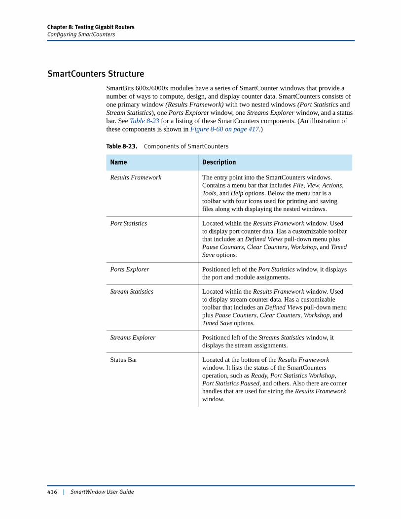
Chapter 8: Testing Gigabit RoutersConfiguring SmartCounters
SmartCounters Structure
SmartBits 600x/6000x modules have a series of SmartCounter windows that provide a number of ways to compute, design, and display counter data. SmartCounters consists of one primary window (Results Framework) with two nested windows (Port Statistics and Stream Statistics), one Ports Explorer window, one Streams Explorer window, and a status bar. See Table 8-23 for a listing of these SmartCounters components. (An illustration of these components is shown in Figure 8-60 on page 417.)
Table 8-23. Components of SmartCounters
Name Description
Results Framework The entry point into the SmartCounters windows. Contains a menu bar that includes File, View, Actions, Tools, and Help options. Below the menu bar is a toolbar with four icons used for printing and saving files along with displaying the nested windows.
Port Statistics Located within the Results Framework window. Used to display port counter data. Has a customizable toolbar that includes an Defined Views pull-down menu plus Pause Counters, Clear Counters, Workshop, and Timed Save options.
Ports Explorer Positioned left of the Port Statistics window, it displays the port and module assignments.
Stream Statistics Located within the Results Framework window. Used to display stream counter data. Has a customizable toolbar that includes an Defined Views pull-down menu plus Pause Counters, Clear Counters, Workshop, and Timed Save options.
Streams Explorer Positioned left of the Streams Statistics window, it displays the stream assignments.
Status Bar Located at the bottom of the Results Framework window. It lists the status of the SmartCounters operation, such as Ready, Port Statistics Workshop, Port Statistics Paused, and others. Also there are corner handles that are used for sizing the Results Framework window.
416 | SmartWindow User Guide
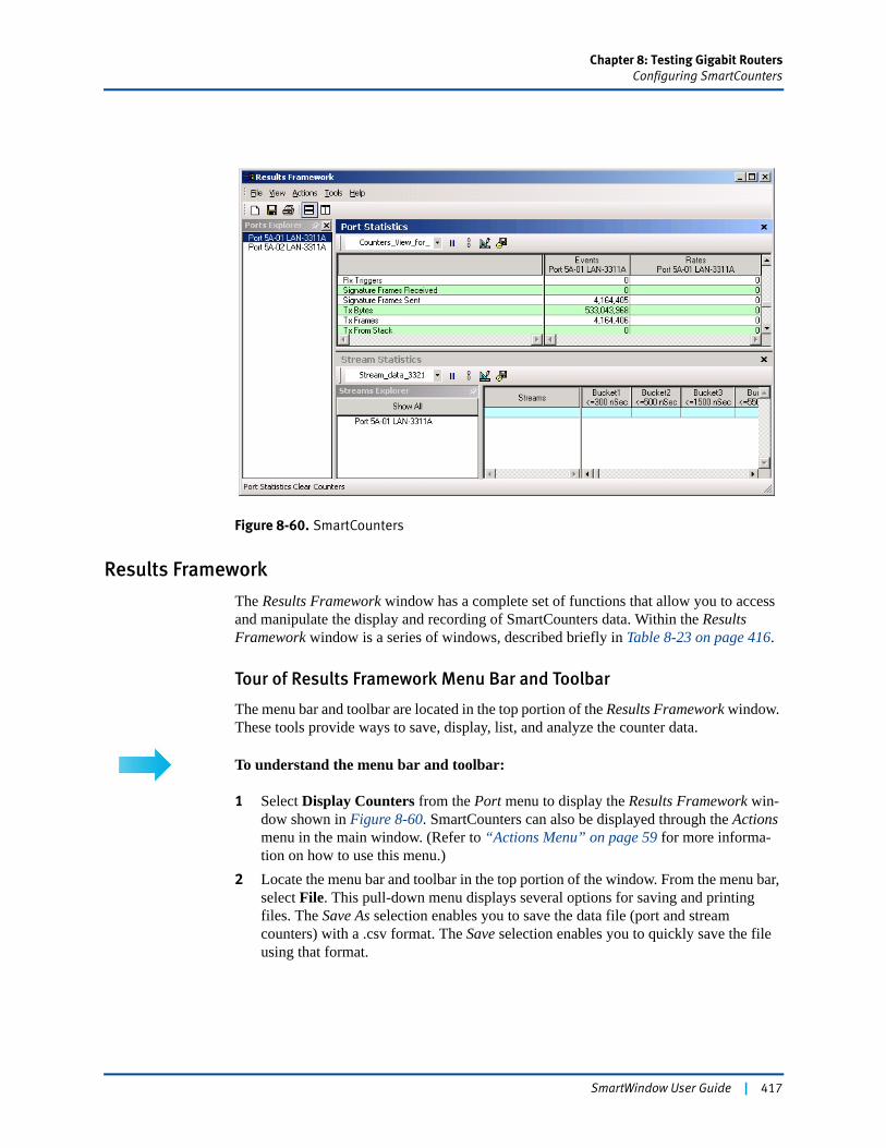
Chapter 8: Testing Gigabit RoutersConfiguring SmartCounters
Figure 8-60. SmartCounters
Results Framework
The Results Framework window has a complete set of functions that allow you to access and manipulate the display and recording of SmartCounters data. Within the Results Framework window is a series of windows, described briefly in Table 8-23 on page 416.
Tour of Results Framework Menu Bar and Toolbar
The menu bar and toolbar are located in the top portion of the Results Framework window. These tools provide ways to save, display, list, and analyze the counter data.
To understand the menu bar and toolbar:
1 Select Display Counters from the Port menu to display the Results Framework win-dow shown in Figure 8-60. SmartCounters can also be displayed through the Actions menu in the main window. (Refer to “Actions Menu” on page 59 for more informa-tion on how to use this menu.)
2 Locate the menu bar and toolbar in the top portion of the window. From the menu bar, select File. This pull-down menu displays several options for saving and printing files. The Save As selection enables you to save the data file (port and stream counters) with a .csv format. The Save selection enables you to quickly save the file using that format.
SmartWindow User Guide | 417
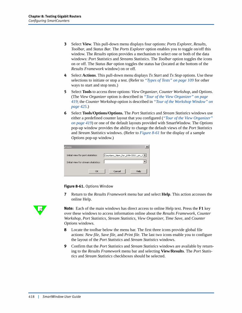
Chapter 8: Testing Gigabit RoutersConfiguring SmartCounters
3 Select View. This pull-down menu displays four options: Ports Explorer, Results, Toolbar, and Status Bar. The Ports Explorer option enables you to toggle on/off this window. The Results option provides a mechanism to select one or both of the data windows: Port Statistics and Streams Statistics. The Toolbar option toggles the icons on or off. The Status Bar option toggles the status bar (located at the bottom of the Results Framework window) on or off.
4 Select Actions. This pull-down menu displays Tx Start and Tx Stop options. Use these selections to initiate or stop a test. (Refer to “Types of Tests” on page 109 for other ways to start and stop tests.)
5 Select Tools to access three options: View Organizer, Counter Workshop, and Options. (The View Organizer option is described in “Tour of the View Organizer” on page 419; the Counter Workshop option is described in “Tour of the Workshop Window” on page 425.)
6 Select Tools/Options/Options. The Port Statistics and Stream Statistics windows use either a predefined counter layout that you configured (“Tour of the View Organizer” on page 419) or one of the default layouts provided with SmartWindow. The Options pop-up window provides the ability to change the default views of the Port Statistics and Stream Statistics windows. (Refer to Figure 8-61 for the display of a sample Options pop-up window.)
Figure 8-61. Options Window
7 Return to the Results Framework menu bar and select Help. This action accesses the online Help.
Note: Each of the main windows has direct access to online Help text. Press the F1 key over these windows to access information online about the Results Framework, Counter Workshop, Port Statistics, Stream Statistics, View Organizer, Time Save, and Counter Options windows.8 Locate the toolbar below the menu bar. The first three icons provide global file
actions: New file, Save file, and Print file. The last two icons enable you to configure the layout of the Port Statistics and Stream Statistics windows.
9 Confirm that the Port Statistics and Stream Statistics windows are available by return-ing to the Results Framework menu bar and selecting View/Results. The Port Statis-tics and Stream Statistics checkboxes should be selected.
418 | SmartWindow User Guide
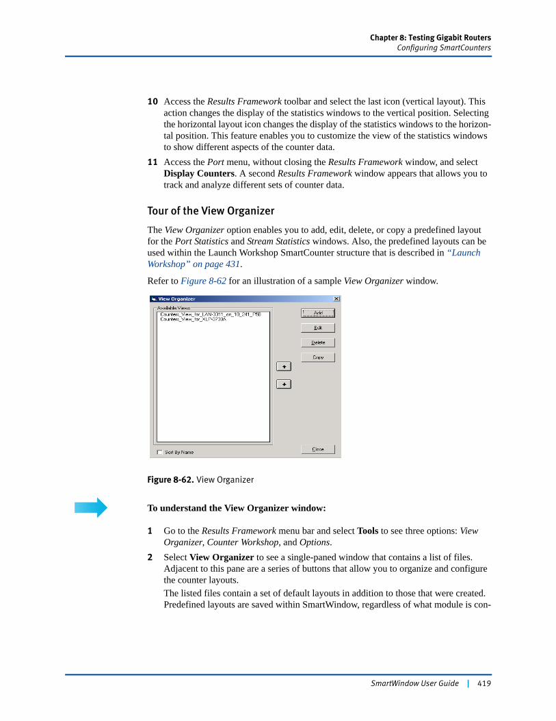
Chapter 8: Testing Gigabit RoutersConfiguring SmartCounters
10 Access the Results Framework toolbar and select the last icon (vertical layout). This action changes the display of the statistics windows to the vertical position. Selecting the horizontal layout icon changes the display of the statistics windows to the horizon-tal position. This feature enables you to customize the view of the statistics windows to show different aspects of the counter data.
11 Access the Port menu, without closing the Results Framework window, and select Display Counters. A second Results Framework window appears that allows you to track and analyze different sets of counter data.
Tour of the View Organizer
The View Organizer option enables you to add, edit, delete, or copy a predefined layout for the Port Statistics and Stream Statistics windows. Also, the predefined layouts can be used within the Launch Workshop SmartCounter structure that is described in “Launch Workshop” on page 431.
Refer to Figure 8-62 for an illustration of a sample View Organizer window.
Figure 8-62. View Organizer
To understand the View Organizer window:
1 Go to the Results Framework menu bar and select Tools to see three options: View Organizer, Counter Workshop, and Options.
2 Select View Organizer to see a single-paned window that contains a list of files. Adjacent to this pane are a series of buttons that allow you to organize and configure the counter layouts. The listed files contain a set of default layouts in addition to those that were created. Predefined layouts are saved within SmartWindow, regardless of what module is con-
SmartWindow User Guide | 419
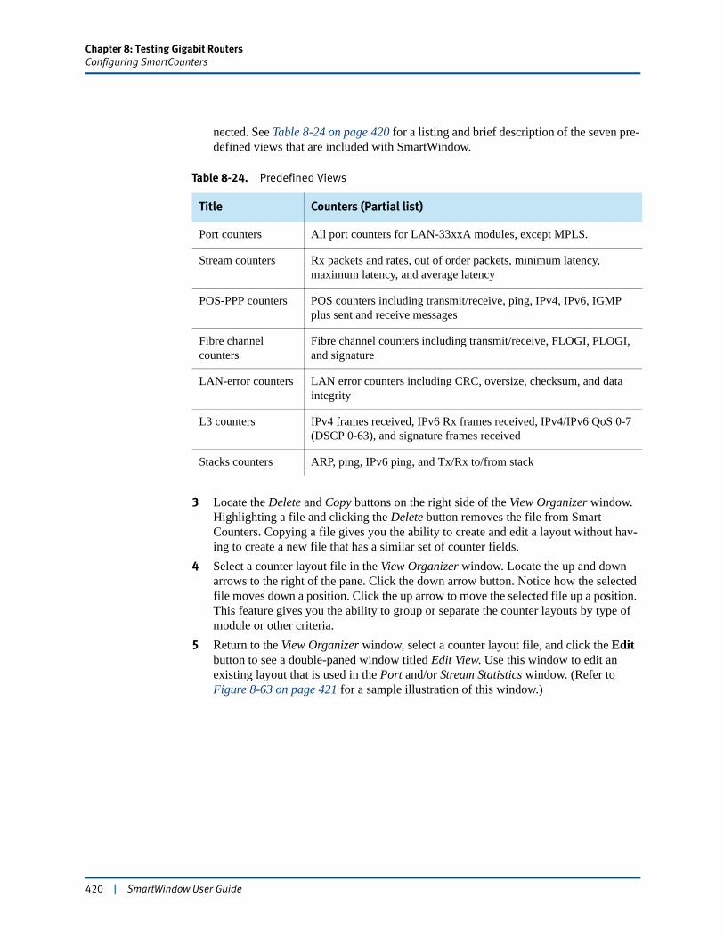
Chapter 8: Testing Gigabit RoutersConfiguring SmartCounters
nected. See Table 8-24 on page 420 for a listing and brief description of the seven pre-defined views that are included with SmartWindow.
3 Locate the Delete and Copy buttons on the right side of the View Organizer window. Highlighting a file and clicking the Delete button removes the file from Smart-Counters. Copying a file gives you the ability to create and edit a layout without hav-ing to create a new file that has a similar set of counter fields.
4 Select a counter layout file in the View Organizer window. Locate the up and down arrows to the right of the pane. Click the down arrow button. Notice how the selected file moves down a position. Click the up arrow to move the selected file up a position. This feature gives you the ability to group or separate the counter layouts by type of module or other criteria.
5 Return to the View Organizer window, select a counter layout file, and click the Edit button to see a double-paned window titled Edit View. Use this window to edit an existing layout that is used in the Port and/or Stream Statistics window. (Refer to Figure 8-63 on page 421 for a sample illustration of this window.)
Table 8-24. Predefined Views
Title Counters (Partial list)
Port counters All port counters for LAN-33xxA modules, except MPLS.
Stream counters Rx packets and rates, out of order packets, minimum latency, maximum latency, and average latency
POS-PPP counters POS counters including transmit/receive, ping, IPv4, IPv6, IGMP plus sent and receive messages
Fibre channel counters
Fibre channel counters including transmit/receive, FLOGI, PLOGI, and signature
LAN-error counters LAN error counters including CRC, oversize, checksum, and data integrity
L3 counters IPv4 frames received, IPv6 Rx frames received, IPv4/IPv6 QoS 0-7 (DSCP 0-63), and signature frames received
Stacks counters ARP, ping, IPv6 ping, and Tx/Rx to/from stack
420 | SmartWindow User Guide
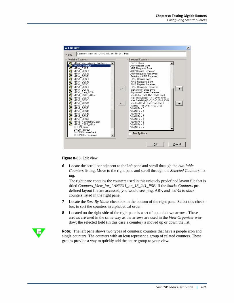
Chapter 8: Testing Gigabit RoutersConfiguring SmartCounters
Figure 8-63. Edit View
6 Locate the scroll bar adjacent to the left pane and scroll through the Available Counters listing. Move to the right pane and scroll through the Selected Counters list-ing.The right pane contains the counters used in this uniquely predefined layout file that is titled Counters_View_for_LAN3311_on_18_241_P5B. If the Stacks Counters pre-defined layout file are accessed, you would see ping, ARP, and Tx/Rx to stack counters listed in the right pane.
7 Locate the Sort By Name checkbox in the bottom of the right pane. Select this check-box to sort the counters in alphabetical order.
8 Located on the right side of the right pane is a set of up and down arrows. These arrows are used in the same way as the arrows are used in the View Organizer win-dow: the selected field (in this case a counter) is moved up or down the list.
Note: The left pane shows two types of counters: counters that have a people icon and single counters. The counters with an icon represent a group of related counters. These groups provide a way to quickly add the entire group to your view.
SmartWindow User Guide | 421
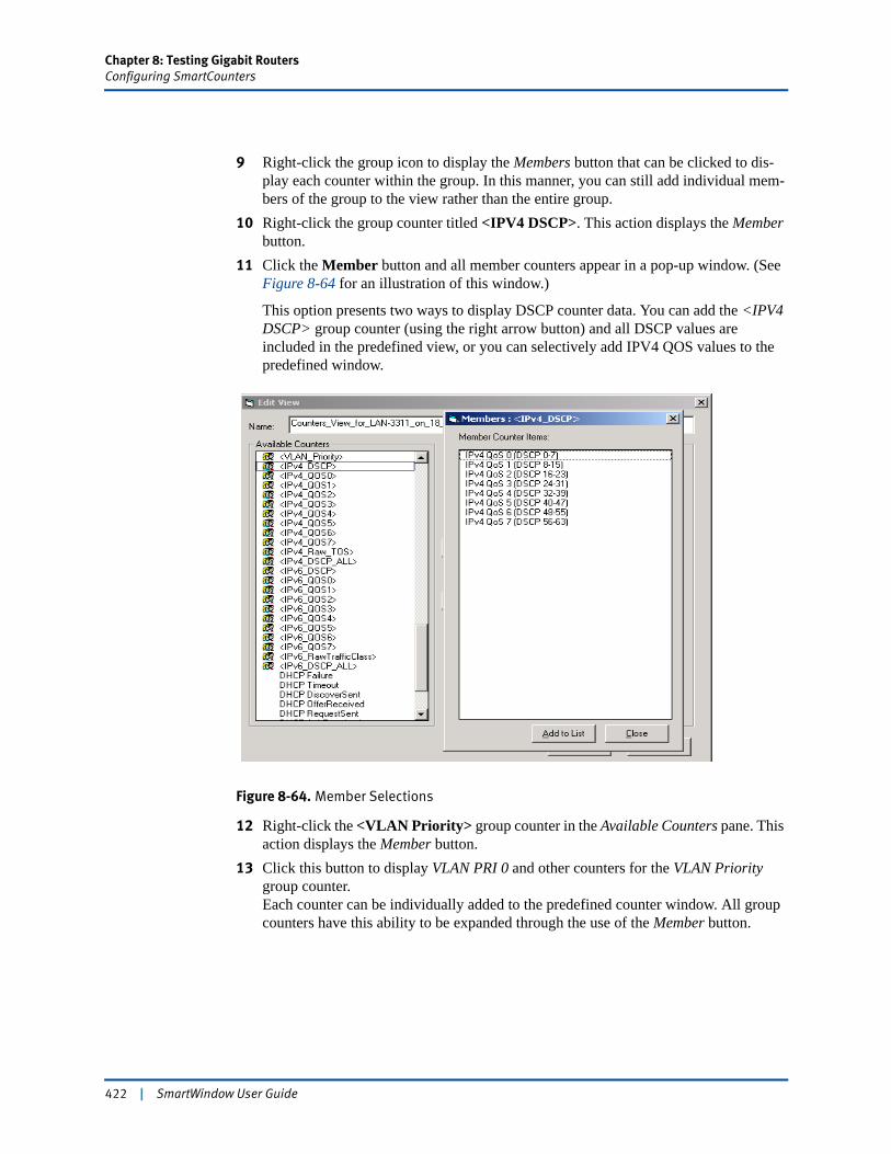
Chapter 8: Testing Gigabit RoutersConfiguring SmartCounters
9 Right-click the group icon to display the Members button that can be clicked to dis-play each counter within the group. In this manner, you can still add individual mem-bers of the group to the view rather than the entire group.
10 Right-click the group counter titled <IPV4 DSCP>. This action displays the Member button.
11 Click the Member button and all member counters appear in a pop-up window. (See Figure 8-64 for an illustration of this window.)
This option presents two ways to display DSCP counter data. You can add the <IPV4 DSCP> group counter (using the right arrow button) and all DSCP values are included in the predefined view, or you can selectively add IPV4 QOS values to the predefined window.
Figure 8-64. Member Selections
12 Right-click the <VLAN Priority> group counter in the Available Counters pane. This action displays the Member button.
13 Click this button to display VLAN PRI 0 and other counters for the VLAN Priority group counter. Each counter can be individually added to the predefined counter window. All group counters have this ability to be expanded through the use of the Member button.
422 | SmartWindow User Guide
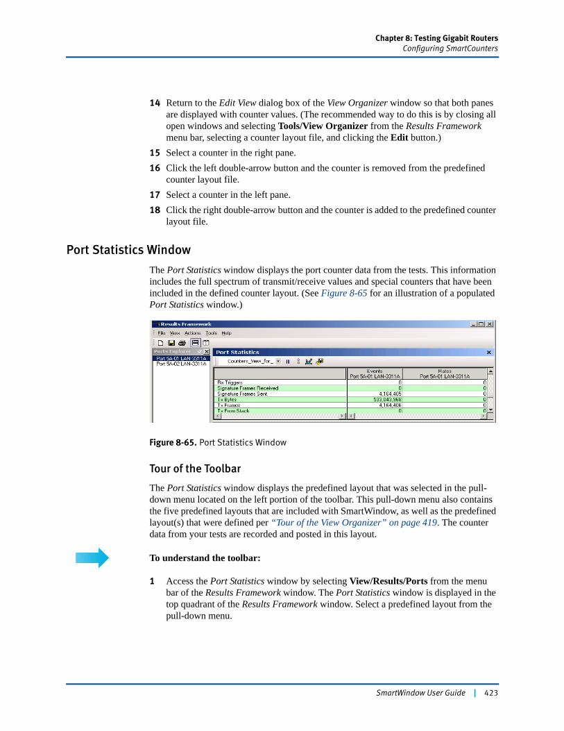
Chapter 8: Testing Gigabit RoutersConfiguring SmartCounters
14 Return to the Edit View dialog box of the View Organizer window so that both panes are displayed with counter values. (The recommended way to do this is by closing all open windows and selecting Tools/View Organizer from the Results Framework menu bar, selecting a counter layout file, and clicking the Edit button.)
15 Select a counter in the right pane. 16 Click the left double-arrow button and the counter is removed from the predefined
counter layout file. 17 Select a counter in the left pane. 18 Click the right double-arrow button and the counter is added to the predefined counter
layout file.
Port Statistics Window
The Port Statistics window displays the port counter data from the tests. This information includes the full spectrum of transmit/receive values and special counters that have been included in the defined counter layout. (See Figure 8-65 for an illustration of a populated Port Statistics window.)
Figure 8-65. Port Statistics Window
Tour of the Toolbar
The Port Statistics window displays the predefined layout that was selected in the pull-down menu located on the left portion of the toolbar. This pull-down menu also contains the five predefined layouts that are included with SmartWindow, as well as the predefined layout(s) that were defined per “Tour of the View Organizer” on page 419. The counter data from your tests are recorded and posted in this layout.
To understand the toolbar:
1 Access the Port Statistics window by selecting View/Results/Ports from the menu bar of the Results Framework window. The Port Statistics window is displayed in the top quadrant of the Results Framework window. Select a predefined layout from the pull-down menu.
SmartWindow User Guide | 423
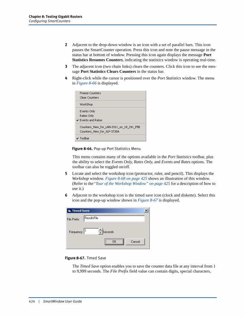
Chapter 8: Testing Gigabit RoutersConfiguring SmartCounters
2 Adjacent to the drop-down window is an icon with a set of parallel bars. This icon pauses the SmartCounter operation. Press this icon and note the pause message in the status bar at bottom of window. Pressing this icon again displays the message Port Statistics Resumes Counters, indicating the statistics window is operating real-time.
3 The adjacent icon (two chain links) clears the counters. Click this icon to see the mes-sage Port Statistics Clears Counters in the status bar.
4 Right-click while the cursor is positioned over the Port Statistics window. The menu in Figure 8-66 is displayed.
Figure 8-66. Pop-up Port Statistics Menu
This menu contains many of the options available in the Port Statistics toolbar, plus the ability to select the Events Only, Rates Only, and Events and Rates options. The toolbar can also be toggled on/off.
5 Locate and select the workshop icon (protractor, ruler, and pencil). This displays the Workshop window. Figure 8-68 on page 425 shows an illustration of this window. (Refer to the“Tour of the Workshop Window” on page 425 for a description of how to use it.)
6 Adjacent to the workshop icon is the timed save icon (clock and diskette). Select this icon and the pop-up window shown in Figure 8-67 is displayed.
Figure 8-67. Timed Save
The Timed Save option enables you to save the counter data file at any interval from 1 to 9,999 seconds. The File Prefix field value can contain digits, special characters,
424 | SmartWindow User Guide
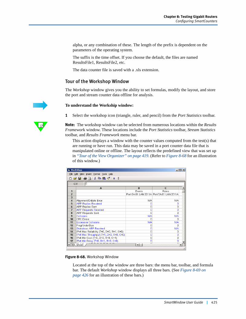
Chapter 8: Testing Gigabit RoutersConfiguring SmartCounters
alpha, or any combination of these. The length of the prefix is dependent on the parameters of the operating system.
The suffix is the time offset. If you choose the default, the files are named ResultsFile1, ResultsFile2, etc.
The data counter file is saved with a .xls extension.
Tour of the Workshop Window
The Workshop window gives you the ability to set formulas, modify the layout, and store the port and stream counter data offline for analysis.
To understand the Workship window:
1 Select the workshop icon (triangle, ruler, and pencil) from the Port Statistics toolbar.
Note: The workshop window can be selected from numerous locations within the Results Framework window. These locations include the Port Statistics toolbar, Stream Statistics toolbar, and Results Framework menu bar.
This action displays a window with the counter values computed from the test(s) that are running or have run. This data may be saved in a port counter data file that is manipulated online or offline. The layout reflects the predefined view that was set up in “Tour of the View Organizer” on page 419. (Refer to Figure 8-68 for an illustration of this window.)
Figure 8-68. Workshop Window
Located at the top of the window are three bars: the menu bar, toolbar, and formula bar. The default Workshop window displays all three bars. (See Figure 8-69 on page 426 for an illustration of these bars.)
SmartWindow User Guide | 425
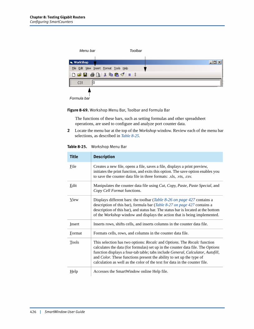
Chapter 8: Testing Gigabit RoutersConfiguring SmartCounters
Figure 8-69. Workshop Menu Bar, Toolbar and Formula Bar
The functions of these bars, such as setting formulas and other spreadsheet operations, are used to configure and analyze port counter data.
2 Locate the menu bar at the top of the Workshop window. Review each of the menu bar selections, as described in Table 8-25.
Table 8-25. Workshop Menu Bar
Title Description
File Creates a new file, opens a file, saves a file, displays a print preview, initiates the print function, and exits this option. The save option enables you to save the counter data file in three formats: .xls, .vts, .csv.
Edit Manipulates the counter data file using Cut, Copy, Paste, Paste Special, and Copy Cell Format functions.
View Displays different bars: the toolbar (Table 8-26 on page 427 contains a description of this bar), formula bar (Table 8-27 on page 427 contains a description of this bar), and status bar. The status bar is located at the bottom of the Workshop window and displays the action that is being implemented.
Insert Inserts rows, shifts cells, and inserts columns in the counter data file.
Format Formats cells, rows, and columns in the counter data file.
Tools This selection has two options: Recalc and Options. The Recalc function calculates the data (for formulas) set up in the counter data file. The Options function displays a four-tab table; tabs include General, Calculator, Autofill, and Color. These functions present the ability to set up the type of calculation as well as the color of the text for data in the counter file.
Help Accesses the SmartWindow online Help file.
Formula bar
Menu bar Toolbar
426 | SmartWindow User Guide

Chapter 8: Testing Gigabit RoutersConfiguring SmartCounters
3 Find the Workshop window toolbar located directly under the menu bar. This toolbar is a series of icons, and it displays only if it has been selected by using the View/Tool-bar option from the menu bar. These toolbar icons are described in Table 8-26.
4 Locate the formula bar (below the toolbar) or select it by accessing the View/Toolbar option from the menu bar. These toolbar menus are described in Table 8-27.
5 Right-click and a pop-up menu displays. This menu contains eight format functions: Format, Cut, Copy, Paste, Clear, Insert, Copy Right, and Copy Down. These are described in Table 8-25 on page 426 and Table 8-26.
Table 8-26. Workshop Toolbar
Title (icon) Description
New (blank page) Creates a new worksheet.
Folder (open folder) Opens an existing counter data file.
Save (diskette) Saves the counter data file using .xls, .vts, or .csv formats.
Printer (printer) Accesses menu to determine when and how to print the counter data file.
Print preview (magnifying glass on paper)
Displays a preview of the printed copy of the counter data file.
Cut (scissors) Cuts a highlighted segment of data.
Copy (two pages) Copies highlighted segment of data.
Paste (page and clipboard) Pastes data located in buffer (from copy function) into selected location in the counter data file.
Format painter (paint brush) Copies format of cells.
Pause (vertical lines) Toggles the start and stop of collecting counter data.
Clear counters (unlinked chain) Clears all data in the counter data file.
Table 8-27. Port Statistics Formula Bar
Title Description
Cell Lists the address of the highlighted cell.
Formula Field Lists the formula in the highlighted cell.
SmartWindow User Guide | 427
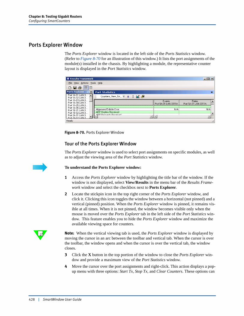
Chapter 8: Testing Gigabit RoutersConfiguring SmartCounters
Ports Explorer Window
The Ports Explorer window is located in the left side of the Ports Statistics window. (Refer to Figure 8-70 for an illustration of this window.) It lists the port assignments of the module(s) installed in the chassis. By highlighting a module, the representative counter layout is displayed in the Port Statistics window.
Figure 8-70. Ports Explorer Window
Tour of the Ports Explorer Window
The Ports Explorer window is used to select port assignments on specific modules, as well as to adjust the viewing area of the Port Statistics window.
To understand the Ports Explorer window:
1 Access the Ports Explorer window by highlighting the title bar of the window. If the window is not displayed, select View/Results in the menu bar of the Results Frame-work window and select the checkbox next to Ports Explorer.
2 Locate the stickpin icon in the top right corner of the Ports Explorer window, and click it. Clicking this icon toggles the window between a horizontal (not pinned) and a vertical (pinned) position. When the Ports Explorer window is pinned, it remains vis-ible at all times. When it is not pinned, the window becomes visible only when the mouse is moved over the Ports Explorer tab in the left side of the Port Statistics win-dow. This feature enables you to hide the Ports Explorer window and maximize the available viewing space for counters.
Note: When the vertical viewing tab is used, the Ports Explorer window is displayed by moving the cursor in an arc between the toolbar and vertical tab. When the cursor is over the toolbar, the window opens and when the cursor is over the vertical tab, the window closes.3 Click the X button in the top portion of the window to close the Ports Explorer win-
dow and provide a maximum view of the Port Statistics window.4 Move the cursor over the port assignments and right-click. This action displays a pop-
up menu with three options: Start Tx, Stop Tx, and Clear Counters. These options can
428 | SmartWindow User Guide
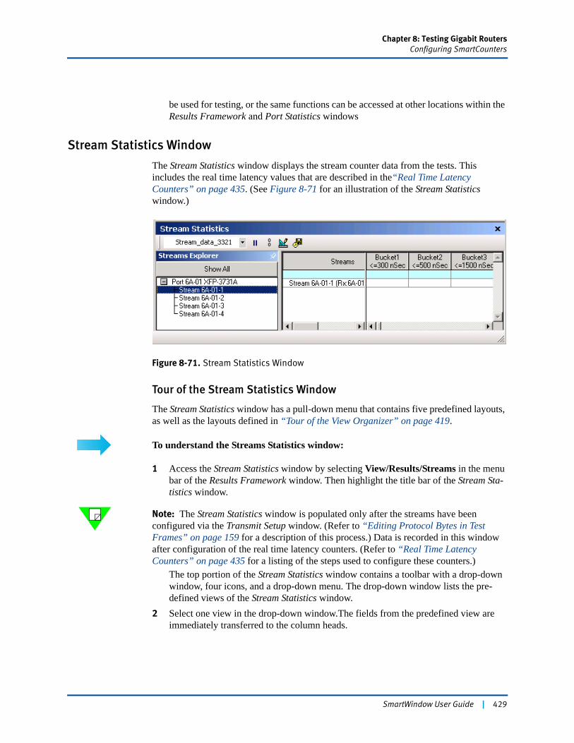
Chapter 8: Testing Gigabit RoutersConfiguring SmartCounters
be used for testing, or the same functions can be accessed at other locations within the Results Framework and Port Statistics windows
Stream Statistics Window
The Stream Statistics window displays the stream counter data from the tests. This includes the real time latency values that are described in the“Real Time Latency Counters” on page 435. (See Figure 8-71 for an illustration of the Stream Statistics window.)
Figure 8-71. Stream Statistics Window
Tour of the Stream Statistics Window
The Stream Statistics window has a pull-down menu that contains five predefined layouts, as well as the layouts defined in “Tour of the View Organizer” on page 419.
To understand the Streams Statistics window:
1 Access the Stream Statistics window by selecting View/Results/Streams in the menu bar of the Results Framework window. Then highlight the title bar of the Stream Sta-tistics window.
Note: The Stream Statistics window is populated only after the streams have been configured via the Transmit Setup window. (Refer to “Editing Protocol Bytes in Test Frames” on page 159 for a description of this process.) Data is recorded in this window after configuration of the real time latency counters. (Refer to “Real Time Latency Counters” on page 435 for a listing of the steps used to configure these counters.)
The top portion of the Stream Statistics window contains a toolbar with a drop-down window, four icons, and a drop-down menu. The drop-down window lists the pre-defined views of the Stream Statistics window.
2 Select one view in the drop-down window.The fields from the predefined view are immediately transferred to the column heads.
SmartWindow User Guide | 429
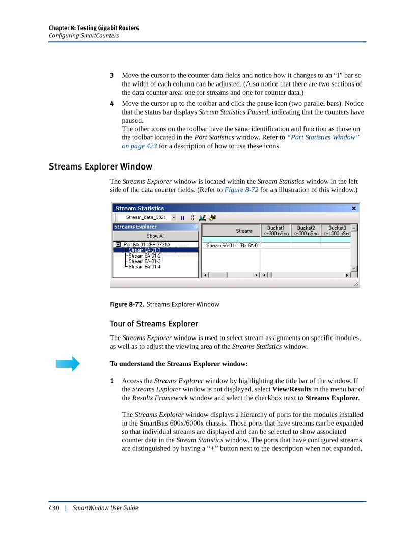
Chapter 8: Testing Gigabit RoutersConfiguring SmartCounters
3 Move the cursor to the counter data fields and notice how it changes to an “I” bar so the width of each column can be adjusted. (Also notice that there are two sections of the data counter area: one for streams and one for counter data.)
4 Move the cursor up to the toolbar and click the pause icon (two parallel bars). Notice that the status bar displays Stream Statistics Paused, indicating that the counters have paused. The other icons on the toolbar have the same identification and function as those on the toolbar located in the Port Statistics window. Refer to “Port Statistics Window” on page 423 for a description of how to use these icons.
Streams Explorer Window
The Streams Explorer window is located within the Stream Statistics window in the left side of the data counter fields. (Refer to Figure 8-72 for an illustration of this window.)
Figure 8-72. Streams Explorer Window
Tour of Streams Explorer
The Streams Explorer window is used to select stream assignments on specific modules, as well as to adjust the viewing area of the Streams Statistics window.
To understand the Streams Explorer window:
1 Access the Streams Explorer window by highlighting the title bar of the window. If the Streams Explorer window is not displayed, select View/Results in the menu bar of the Results Framework window and select the checkbox next to Streams Explorer.
The Streams Explorer window displays a hierarchy of ports for the modules installed in the SmartBits 600x/6000x chassis. Those ports that have streams can be expanded so that individual streams are displayed and can be selected to show associated counter data in the Stream Statistics window. The ports that have configured streams are distinguished by having a “+” button next to the description when not expanded.
430 | SmartWindow User Guide

Chapter 8: Testing Gigabit RoutersConfiguring SmartCounters
Clicking the + button expands the port description to display the streams. The expan-sion button also changes to a -.
2 Locate the stickpin icon in the top right corner of the Streams Explorer window, and click it. Clicking on this icon toggles the window between a horizontal (not pinned) and a vertical (pinned) position. When the Streams Explorer window is pinned, it remains visible at all times. When it is not pinned, the window becomes visible only when the mouse is moved over the Streams Explorer tab on the left side of the Stream Statistics window. This feature enables you to hide the Streams Explorer window and maximize the available viewing space for counters.
Below the title bar is the Show All bar. The operation of this bar works in conjunction with the selections highlighted in the Ports Explorer window. Selecting a port or series of ports in the Ports Explorer window automatically causes the population of those same ports in the Streams Explorer window.
3 Highlight a series of ports (that have streams) in the Ports Explorer window.4 Click the Show All bar and all the ports/streams in the Streams Explorer window
become visible. This function enables you to simultaneously and selectively view and record data in the Port Statistics and Stream Statistics windows.
Launch Workshop
The Launch Workshop option is located in the Actions window. (See “Actions Menu” on page 59 for a description of how to access this selection.) Selecting Launch Workshop displays the Workshop Selector window. (Refer to Figure 8-73 on page 432 for an illustration of this two-tabbed window.)
The Launch Workshop option enables you to configure, display, and analyze SmartCounters. It is different from the Results Framework SmartCounter function because port and stream data can be displayed on one data window. Within the Results Framework structure, port data is displayed in the Port Statistics window and stream data is displayed in the Stream Statistics window.
SmartWindow User Guide | 431
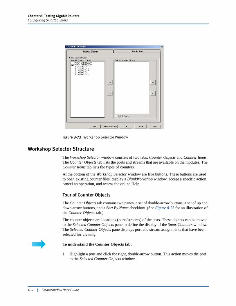
Chapter 8: Testing Gigabit RoutersConfiguring SmartCounters
Figure 8-73. Workshop Selector Window
Workshop Selector Structure
The Workshop Selector window consists of two tabs: Counter Objects and Counter Items. The Counter Objects tab lists the ports and streams that are available on the modules. The Counter Items tab lists the types of counters.
At the bottom of the Workshop Selector window are five buttons. These buttons are used to open existing counter files, display a BlankWorkshop window, accept a specific action, cancel an operation, and access the online Help.
Tour of Counter Objects
The Counter Objects tab contains two panes, a set of double-arrow buttons, a set of up and down arrow buttons, and a Sort By Name checkbox. (See Figure 8-73 for an illustration of the Counter Objects tab.)
The counter objects are locations (ports/streams) of the tests. These objects can be moved to the Selected Counter Objects pane to define the display of the SmartCounters window. The Selected Counter Objects pane displays port and stream assignments that have been selected for viewing.
To understand the Counter Objects tab:
1 Highlight a port and click the right, double-arrow button. This action moves the port to the Selected Counter Objects window.
432 | SmartWindow User Guide
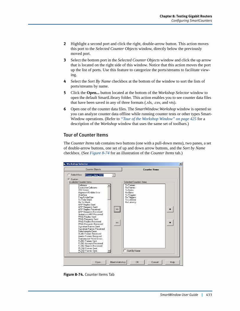
Chapter 8: Testing Gigabit RoutersConfiguring SmartCounters
2 Highlight a second port and click the right, double-arrow button. This action moves this port to the Selected Counter Objects window, directly below the previously moved port.
3 Select the bottom port in the Selected Counter Objects window and click the up arrow that is located on the right side of this window. Notice that this action moves the port up the list of ports. Use this feature to categorize the ports/streams to facilitate view-ing.
4 Select the Sort By Name checkbox at the bottom of the window to sort the lists of ports/streams by name.
5 Click the Open... button located at the bottom of the Workshop Selector window to open the default SmartLibrary folder. This action enables you to see counter data files that have been saved in any of three formats (.xls, .csv, and vts).
6 Open one of the counter data files. The SmartWindow:Workshop window is opened so you can analyze counter data offline while running counter tests or other types Smart-Window operations. (Refer to “Tour of the Workshop Window” on page 425 for a description of the Workshop window that uses the same set of toolbars.)
Tour of Counter Items
The Counter Items tab contains two buttons (one with a pull-down menu), two panes, a set of double-arrow buttons, one set of up and down arrow buttons, and the Sort by Name checkbox. (See Figure 8-74 for an illustration of the Counter Items tab.)
Figure 8-74. Counter Items Tab
SmartWindow User Guide | 433

Chapter 8: Testing Gigabit RoutersConfiguring SmartCounters
To understand the Counter Items tab:
1 Click the Custom button in the Available Counter Items window. Clicking the Cus-tom button makes accessible all of the counters listed in the Available Counter Items window. Use the double-arrow keys to move counters to the Selected Counter Items pane and create a counter window that meets the test requirements.
2 Locate the up and down arrows and the Sort By Name checkbox. These items have same function as those described in the Counter Objects tab (on page 433). Configure a counter window for your test fixture using these arrows and selections.
3 Start the test and then click the OK button in the Workshop Selector window. The SmartWindow Workshop window is displayed with the counters incrementing accord-ing to the results of the test. (Refer to Figure 8-75 for an illustration of this window.)
Figure 8-75. SmartWindow: Workshop
The toolbars and operation of this window are identical to those used in the Workshop window that is located within the Results Framework window. (Refer to “Results Framework” on page 417 for an explanation of how to use the Results Framework window in defining counter data windows. See “Tour of the Workshop Window” on page 425 for a description of the toolbars and operation of the Workshop window.)
4 Stop the test and save the data counter file using the File menu option in the menu bar. 5 Locate and click the Select View button on the Counter Items tab. The Available
Counter Items are unavailable, and the pull-down menu is highlighted.
434 | SmartWindow User Guide
Chapter 8: Testing Gigabit RoutersRunning SmartCounters
6 Click the pull-down menu and scroll through the selections. These selections are pre-defined windows of SmartCounter data displays. Each selection lists counters in a sequence that is defined by you and/or are one of the seven layouts provided with the SmartWindow test application. (See Table 8-24 on page 420 for a listing of these counter layout files.)
7 Highlight one of these selections, and press the OK button. The SmartWindow:Work-shop window opens showing the data counter layout of the predefined window. (Refer to “Tour of the View Organizer” on page 419 for an explanation of how to use the View Organizer in configuring SmartCounter data windows.)
8 Click the BlankWorkshop button at the bottom of the Workshop Selector window. A blank workshop window is displayed that can be used to load and analyze data counter files.
Running SmartCountersSmart Counters is started from the following locations:
• Within the Actions Menu. (Refer to “Actions Menu” on page 59.)
• Within the Port Menu. (Refer to “Capturing Packets” on page 148.)
After SmartCounters is configured, the test(s) are initiated from the following locations:
• Within SmartCounters. (Refer to “Tour of Results Framework Menu Bar and Toolbar” on page 417.)
• From the main toolbar. (Refer to “Real Time Latency Test” on page 298.)
• From the front panel of the virtual chassis. (Refer to “Connected to SmartBits 600x/6000x” on page 53.)
You can view SmartCounters data online or offline from two locations: through the Results Framework window (“Configuring Transmit Streams on TeraMetrics Modules” on page 392) or through the Workshop Selector window (“Launch Workshop” on page 431).
Real Time Latency Counters
Latency testing requires the configuration of streams (“Editing Protocol Bytes in Test Frames” on page 159) and buckets that specify the time intervals of the latency values. The buckets are configured on the main toolbar by accessing Tests/Realtime Latency Test. (Refer to “Real Time Latency Test” on page 298 for a description of this process.)
The real time latency counters are displayed in a SmartCounters predefined window. This process is described starting with “Tour of the View Organizer” on page 419. (Refer to Figure 8-76 on page 436 for an illustration of the Stream Statistics window for one type of real time latency counter display. This Stream Statistics window is positioned vertically with the Ports Statistic window headlined. Refer to “Tour of Results Framework Menu
SmartWindow User Guide | 435
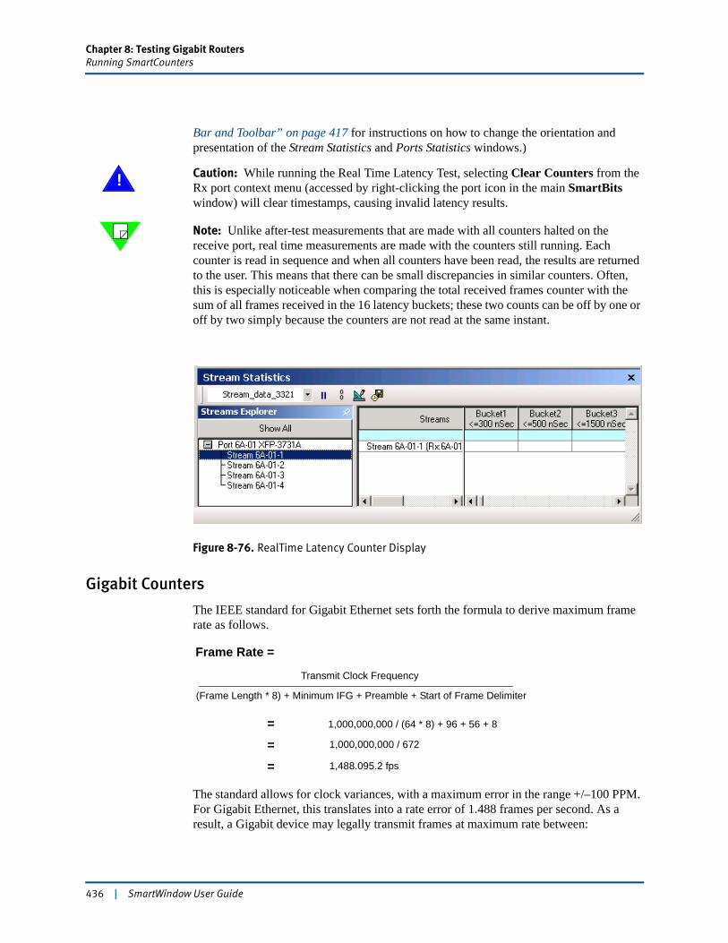
Chapter 8: Testing Gigabit RoutersRunning SmartCounters
Bar and Toolbar” on page 417 for instructions on how to change the orientation and presentation of the Stream Statistics and Ports Statistics windows.)
! Caution: While running the Real Time Latency Test, selecting Clear Counters from the Rx port context menu (accessed by right-clicking the port icon in the main SmartBits window) will clear timestamps, causing invalid latency results.
Note: Unlike after-test measurements that are made with all counters halted on the receive port, real time measurements are made with the counters still running. Each counter is read in sequence and when all counters have been read, the results are returned to the user. This means that there can be small discrepancies in similar counters. Often, this is especially noticeable when comparing the total received frames counter with the sum of all frames received in the 16 latency buckets; these two counts can be off by one or off by two simply because the counters are not read at the same instant.
Figure 8-76. RealTime Latency Counter Display
Gigabit Counters
The IEEE standard for Gigabit Ethernet sets forth the formula to derive maximum frame rate as follows.
The standard allows for clock variances, with a maximum error in the range +/–100 PPM. For Gigabit Ethernet, this translates into a rate error of 1.488 frames per second. As a result, a Gigabit device may legally transmit frames at maximum rate between:
Frame Rate =
Transmit Clock Frequency
(Frame Length * 8) + Minimum IFG + Preamble + Start of Frame Delimiter
1,000,000,000 / (64 * 8) + 96 + 56 + 8
1,000,000,000 / 672
==
1,488.095.2 fps=
436 | SmartWindow User Guide

Chapter 8: Testing Gigabit RoutersRunning SmartCounters
1,487,946.4 fps— and —1,488,244.0 fps
For 10 Gigabit Ethernet, the formula described above applies but with the transmit clock rate multiplied by a factor of 10. The resulting frames per second rate, at wire speed and with minimum frame size and interframe gap, is 14,880,952 frames per second.
The standard allows for clock variances, with a maximum error in the range +/–100 PPM. For 10 Gigabit Ethernet, this translates into a rate error of 14.88 frames per second. As a result, a 10 Gigabit device may legally transmit frames at maximum rate between:
14,879,464 fps— and —14,882,440 fps
DiffServ Counters
Selected Gigabit modules, including the LAN-3710AL/AE, XLW-3720A/3721A, and XFP-3730/3731 10 Gigabit modules support DiffServ tracking on the receiving port. When this option is enabled, the port examines a specified byte in the frame and records the byte value.
Some DiffServ counters are implemented differently for IPv4 and IPv6 applications as well as different modules. For example, IPv4 applications have an option for counting the number of received frames that contain a Type of Service (TOS) byte. These applications also tally the number of frames with specific TOS values. All other DiffServ counters are implemented for both IPv4 and IPv6 applications, including all QOS values.
Note: See Table 8-28 and Table 8-29 on page 438 for the functional differences in the configuration of DiffServ counters for selected Ethernet modules.
Table 8-28. Modules That Support DiffServ Counters/Rates
ModuleIPv4 DiffServ Counters/Rates
IPv6 DiffServ Counters/Rates
LAN-330xA Yes No
LAN-331xA Yes No
LAN-3306A/LAN-332xA
Yes Yes
LAN-3710AL/AE Yes No
XLW-3720A/3721A XFP-3730A/3731A
Yes Yes
SmartWindow User Guide | 437
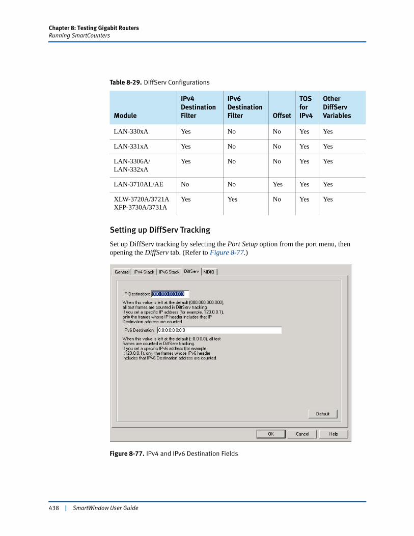
Chapter 8: Testing Gigabit RoutersRunning SmartCounters
Setting up DiffServ Tracking
Set up DiffServ tracking by selecting the Port Setup option from the port menu, then opening the DiffServ tab. (Refer to Figure 8-77.)
Figure 8-77. IPv4 and IPv6 Destination Fields
Table 8-29. DiffServ Configurations
Module
IPv4 Destination Filter
IPv6 Destination Filter Offset
TOS for IPv4
Other DiffServ Variables
LAN-330xA Yes No No Yes Yes
LAN-331xA Yes No No Yes Yes
LAN-3306A/LAN-332xA
Yes No No Yes Yes
LAN-3710AL/AE No No Yes Yes Yes
XLW-3720A/3721A XFP-3730A/3731A
Yes Yes No Yes Yes
438 | SmartWindow User Guide
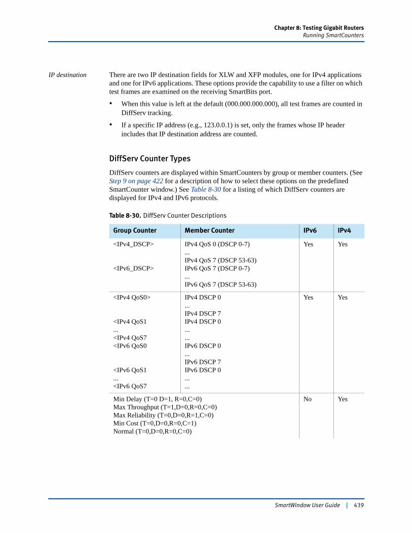
Chapter 8: Testing Gigabit RoutersRunning SmartCounters
IP destination There are two IP destination fields for XLW and XFP modules, one for IPv4 applications and one for IPv6 applications. These options provide the capability to use a filter on which test frames are examined on the receiving SmartBits port.
• When this value is left at the default (000.000.000.000), all test frames are counted in DiffServ tracking.
• If a specific IP address (e.g., 123.0.0.1) is set, only the frames whose IP header includes that IP destination address are counted.
DiffServ Counter Types
DiffServ counters are displayed within SmartCounters by group or member counters. (See Step 9 on page 422 for a description of how to select these options on the predefined SmartCounter window.) See Table 8-30 for a listing of which DiffServ counters are displayed for IPv4 and IPv6 protocols.
Table 8-30. DiffServ Counter Descriptions
Group Counter Member Counter IPv6 IPv4
<IPv4_DSCP>
<IPv6_DSCP>
IPv4 QoS 0 (DSCP 0-7)...IPv4 QoS 7 (DSCP 53-63)IPv6 QoS 7 (DSCP 0-7)...IPv6 QoS 7 (DSCP 53-63)
Yes Yes
<IPv4 QoS0>
<IPv4 QoS1...<IPv4 QoS7<IPv6 QoS0
<IPv6 QoS1...<IPv6 QoS7
IPv4 DSCP 0...IPv4 DSCP 7IPv4 DSCP 0......IPv6 DSCP 0...IPv6 DSCP 7IPv6 DSCP 0......
Yes Yes
Min Delay (T=0 D=1, R=0,C=0) Max Throughput (T=1,D=0,R=0,C=0)Max Reliability (T=0,D=0,R=1,C=0)Min Cost (T=0,D=0,R=0,C=1)Normal (T=0,D=0,R=0,C=0)
No Yes
SmartWindow User Guide | 439
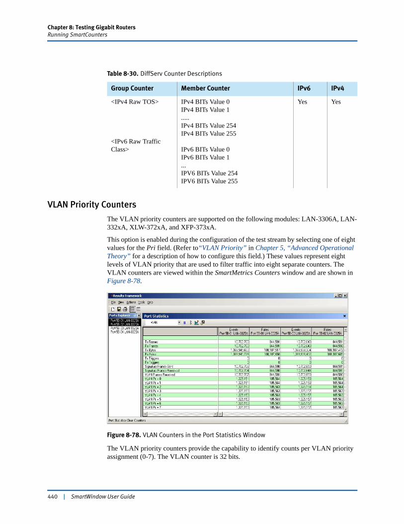
Chapter 8: Testing Gigabit RoutersRunning SmartCounters
VLAN Priority Counters
The VLAN priority counters are supported on the following modules: LAN-3306A, LAN-332xA, XLW-372xA, and XFP-373xA.
This option is enabled during the configuration of the test stream by selecting one of eight values for the Pri field. (Refer to“VLAN Priority” in Chapter 5, “Advanced Operational Theory” for a description of how to configure this field.) These values represent eight levels of VLAN priority that are used to filter traffic into eight separate counters. The VLAN counters are viewed within the SmartMetrics Counters window and are shown in Figure 8-78.
Figure 8-78. VLAN Counters in the Port Statistics Window
The VLAN priority counters provide the capability to identify counts per VLAN priority assignment (0-7). The VLAN counter is 32 bits.
<IPv4 Raw TOS>
<IPv6 Raw Traffic Class>
IPv4 BITs Value 0IPv4 BITs Value 1.....IPv4 BITs Value 254IPv4 BITs Value 255
IPv6 BITs Value 0IPv6 BITs Value 1...IPV6 BITs Value 254IPV6 BITs Value 255
Yes Yes
Table 8-30. DiffServ Counter Descriptions
Group Counter Member Counter IPv6 IPv4
440 | SmartWindow User Guide
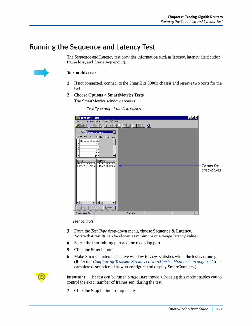
Chapter 8: Testing Gigabit RoutersRunning the Sequence and Latency Test
Running the Sequence and Latency TestThe Sequence and Latency test provides information such as latency, latency distribution, frame loss, and frame sequencing.
To run this test:
1 If not connected, connect to the SmartBits 6000x chassis and reserve two ports for the test.
2 Choose Options > SmartMetrics Tests.The SmartMetrics window appears.
3 From the Test Type drop-down menu, choose Sequence & Latency. Notice that results can be shown as minimum or average latency values.
4 Select the transmitting port and the receiving port.5 Click the Start button.6 Make SmartCounters the active window to view statistics while the test is running.
(Refer to “Configuring Transmit Streams on TeraMetrics Modules” on page 392 for a complete description of how to configure and display SmartCounters.)
Important: The test can be run in Single Burst mode. Choosing this mode enables you to control the exact number of frames sent during the test.
7 Click the Stop button to stop the test.
Test Type drop-down field values
Tx and Rxcheckboxes
Test controls
SmartWindow User Guide | 441
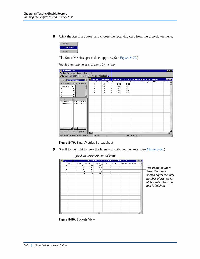
Chapter 8: Testing Gigabit RoutersRunning the Sequence and Latency Test
8 Click the Results button, and choose the receiving card from the drop-down menu.
The SmartMetrics spreadsheet appears.(See Figure 8-79.)
Figure 8-79. SmartMetrics Spreadsheet
9 Scroll to the right to view the latency distribution buckets. (See Figure 8-80.)
Figure 8-80. Buckets View
The Stream column lists streams by number.
Buckets are incremented in μs.
The frame count in SmartCounters should equal the total number of frames for all buckets when the test is finished.
442 | SmartWindow User Guide
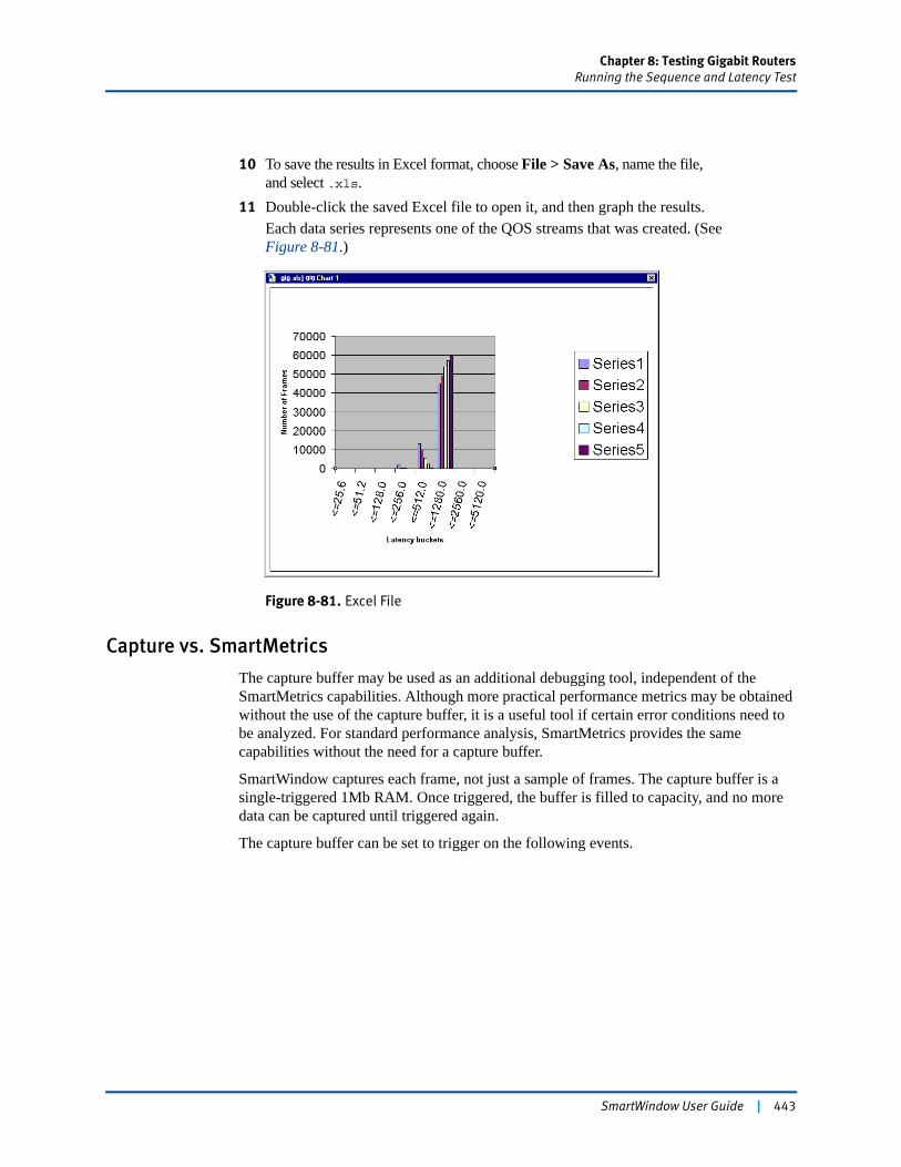
Chapter 8: Testing Gigabit RoutersRunning the Sequence and Latency Test
10 To save the results in Excel format, choose File > Save As, name the file,and select .xls.
11 Double-click the saved Excel file to open it, and then graph the results.Each data series represents one of the QOS streams that was created. (See Figure 8-81.)
Figure 8-81. Excel File
Capture vs. SmartMetrics
The capture buffer may be used as an additional debugging tool, independent of the SmartMetrics capabilities. Although more practical performance metrics may be obtained without the use of the capture buffer, it is a useful tool if certain error conditions need to be analyzed. For standard performance analysis, SmartMetrics provides the same capabilities without the need for a capture buffer.
SmartWindow captures each frame, not just a sample of frames. The capture buffer is a single-triggered 1Mb RAM. Once triggered, the buffer is filled to capacity, and no more data can be captured until triggered again.
The capture buffer can be set to trigger on the following events.
SmartWindow User Guide | 443
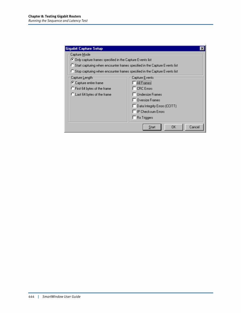
Chapter 8: Testing Gigabit RoutersRunning the Sequence and Latency Test
444 | SmartWindow User Guide
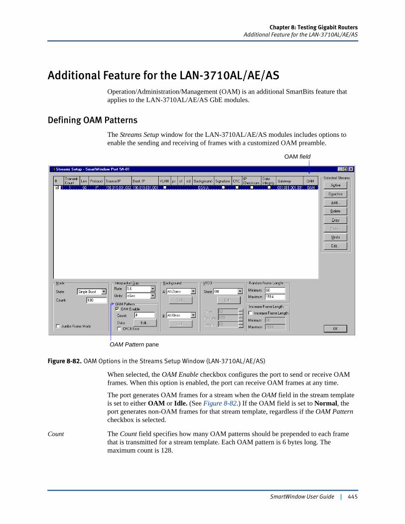
Chapter 8: Testing Gigabit RoutersAdditional Feature for the LAN-3710AL/AE/AS
Additional Feature for the LAN-3710AL/AE/ASOperation/Administration/Management (OAM) is an additional SmartBits feature that applies to the LAN-3710AL/AE/AS GbE modules.
Defining OAM Patterns
The Streams Setup window for the LAN-3710AL/AE/AS modules includes options to enable the sending and receiving of frames with a customized OAM preamble.
Figure 8-82. OAM Options in the Streams Setup Window (LAN-3710AL/AE/AS)
When selected, the OAM Enable checkbox configures the port to send or receive OAM frames. When this option is enabled, the port can receive OAM frames at any time.
The port generates OAM frames for a stream when the OAM field in the stream template is set to either OAM or Idle. (See Figure 8-82.) If the OAM field is set to Normal, the port generates non-OAM frames for that stream template, regardless if the OAM Pattern checkbox is selected.
Count The Count field specifies how many OAM patterns should be prepended to each frame that is transmitted for a stream template. Each OAM pattern is 6 bytes long. The maximum count is 128.
OAM Pattern pane
OAM field
SmartWindow User Guide | 445
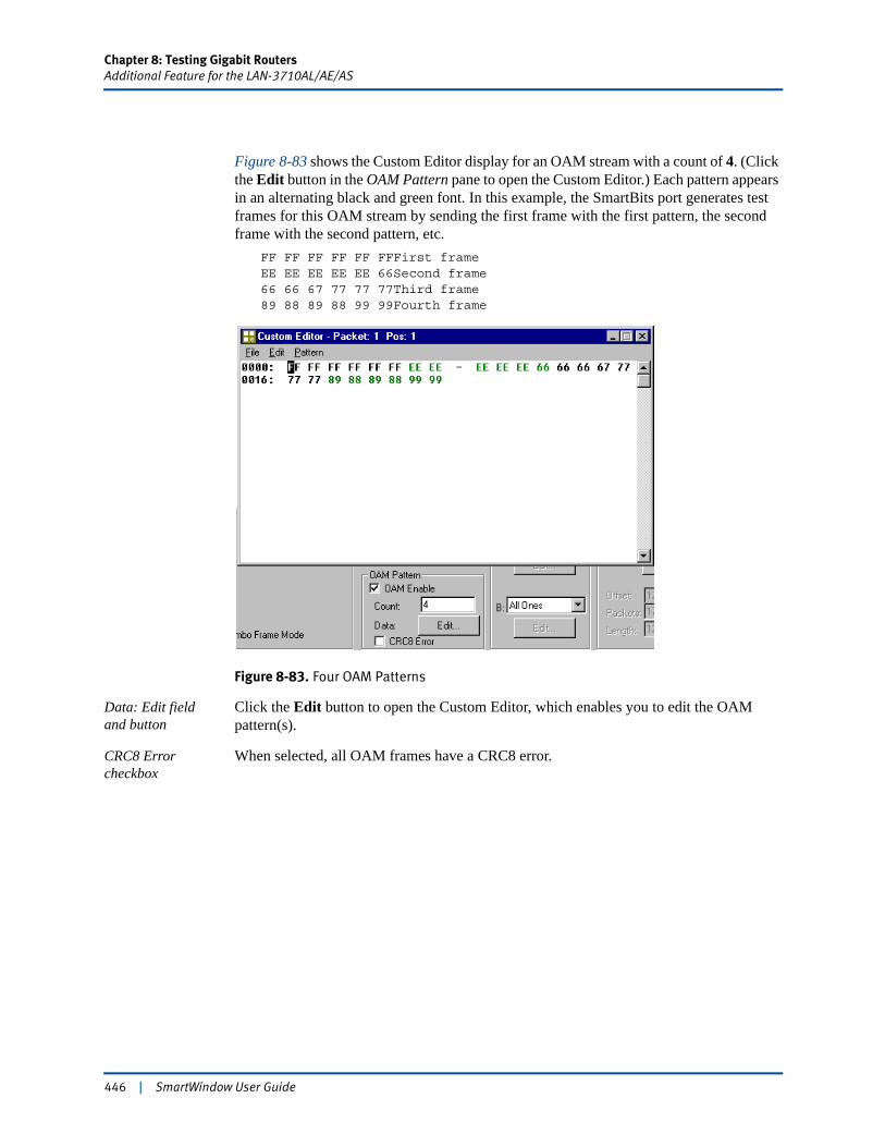
Chapter 8: Testing Gigabit RoutersAdditional Feature for the LAN-3710AL/AE/AS
Figure 8-83 shows the Custom Editor display for an OAM stream with a count of 4. (Click the Edit button in the OAM Pattern pane to open the Custom Editor.) Each pattern appears in an alternating black and green font. In this example, the SmartBits port generates test frames for this OAM stream by sending the first frame with the first pattern, the second frame with the second pattern, etc.
FF FF FF FF FF FFFirst frameEE EE EE EE EE 66Second frame66 66 67 77 77 77Third frame89 88 89 88 99 99Fourth frame
Figure 8-83. Four OAM Patterns
Data: Edit field and button
Click the Edit button to open the Custom Editor, which enables you to edit the OAM pattern(s).
CRC8 Error checkbox
When selected, all OAM frames have a CRC8 error.
446 | SmartWindow User Guide
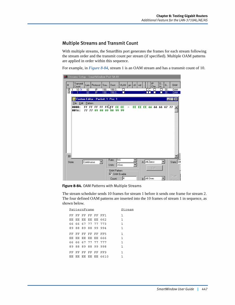
Chapter 8: Testing Gigabit RoutersAdditional Feature for the LAN-3710AL/AE/AS
Multiple Streams and Transmit Count
With multiple streams, the SmartBits port generates the frames for each stream following the stream order and the transmit count per stream (if specified). Multiple OAM patterns are applied in order within this sequence.
For example, in Figure 8-84, stream 1 is an OAM stream and has a transmit count of 10.
Figure 8-84. OAM Patterns with Multiple Streams
The stream scheduler sends 10 frames for stream 1 before it sends one frame for stream 2. The four defined OAM patterns are inserted into the 10 frames of stream 1 in sequence, as shown below.
PatternFrame Stream
FF FF FF FF FF FF1 1EE EE EE EE EE 662 166 66 67 77 77 773 189 88 89 88 99 994 1
FF FF FF FF FF FF5 1EE EE EE EE EE 666 166 66 67 77 77 777 189 88 89 88 99 998 1
FF FF FF FF FF FF9 1EE EE EE EE EE 6610 1
SmartWindow User Guide | 447
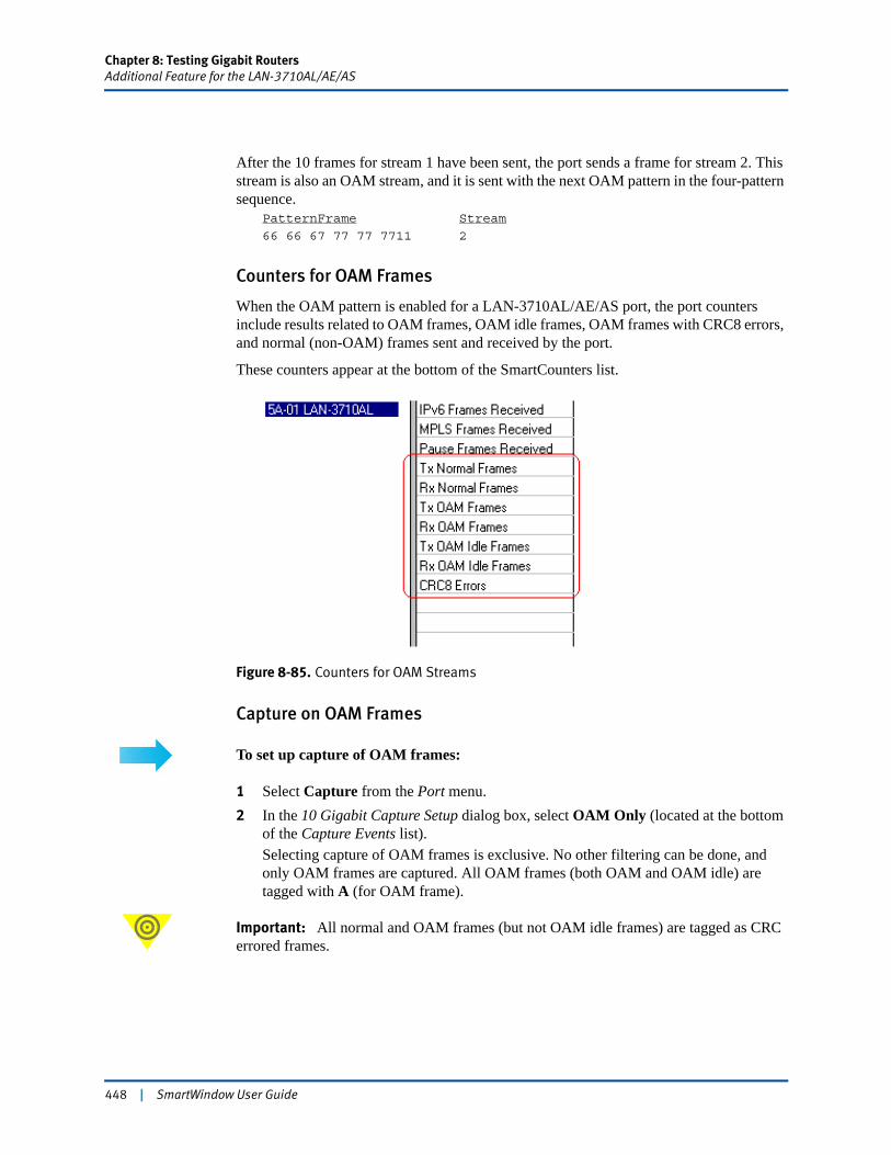
Chapter 8: Testing Gigabit RoutersAdditional Feature for the LAN-3710AL/AE/AS
After the 10 frames for stream 1 have been sent, the port sends a frame for stream 2. This stream is also an OAM stream, and it is sent with the next OAM pattern in the four-pattern sequence.
PatternFrame Stream
66 66 67 77 77 7711 2
Counters for OAM Frames
When the OAM pattern is enabled for a LAN-3710AL/AE/AS port, the port counters include results related to OAM frames, OAM idle frames, OAM frames with CRC8 errors, and normal (non-OAM) frames sent and received by the port.
These counters appear at the bottom of the SmartCounters list.
Figure 8-85. Counters for OAM Streams
Capture on OAM Frames
To set up capture of OAM frames:
1 Select Capture from the Port menu. 2 In the 10 Gigabit Capture Setup dialog box, select OAM Only (located at the bottom
of the Capture Events list).Selecting capture of OAM frames is exclusive. No other filtering can be done, and only OAM frames are captured. All OAM frames (both OAM and OAM idle) are tagged with A (for OAM frame).
Important: All normal and OAM frames (but not OAM idle frames) are tagged as CRC errored frames.
448 | SmartWindow User Guide
Chapter 9
Testing Frame Relay Switches
This chapter describes how to use SmartWindow and the frame relay family of WAN SmartCards to evaluate the performance of frame relay devices. It includes two setup procedures for:
• The WN-3445A Channelized DS3 SmartCard. (Refer to“Test Using the WN-3445A Channelized DS3 SmartCard” on page 454.)
• The WN-3405 Fractional T1 SmartCard. (Refer to “Test Using WN-3405 T1 SmartCards” on page 492.)
See also “Additional Features for WAN Cards” for capabilities and options not covered by the setup examples. These sections include:
• “Duplicate PVCs Easily” on page 508
• “Adjust Incorrect Number of PVCs” on page 509
• “Use Different Transmit Modes” on page 510
• “Perform SmartMetrics Tests” on page 512
• “Define a Frame Distribution Method” on page 513
• “Set up IGMP Streams on WAN Cards” on page 514.
In this chapter...
• About T1/DS3 Data Networking . . . . 450
• Characteristics of a Frame Relay Switch . . . . 452
• Testing for Throughput Capacity . . . . 453
• Test Using the WN-3445A Channelized DS3 SmartCard . . . . 454
• Test Using WN-3405 T1 SmartCards . . . . 492
• Additional Features for WAN Cards . . . . 508
SmartWindow User Guide | 449

Chapter 9: Testing Frame Relay SwitchesAbout T1/DS3 Data Networking
About T1/DS3 Data NetworkingT1 digital transmission technology was developed for use in telephone voice communications. In digital form, one voice signal requires 64,000 bits per second (64 Kbps). This basic channel unit was designated Digital Signal Level 0 (DS0). When 24 DS0 channels are multiplexed, the aggregate data rate is 1,536,000 bps. An additional 8,000 bps is used to keep the multiplexers synchronized at each end of the link. This brings the total data rate to 1,544,000 bps or 1.544 Mbps, the standard T1 rate.
Data Signal Level Three (DS3) was developed as carriers of major routes realized the need for a faster rate than T1. The DS3 rate of 44.736 Mbps is equivalent to the capacity of 28 T1s, plus additional overhead.
Fractional, Channelized, and Clear Channel Transmission
Fractional The earlier WAN T1 SmartCard (the WN-3415) is fractional: it provides a channel over over one port (line), and it enables you to select and transmit using a subset of the DS0s available in the T1 line.
Channelized The channelized T1 and DS3 SmartCards (the WN-3441A or WN-3445A) enable you to create multiple individual channels within a T1 line, assigning one or more DS0s to each channel.
Clear channel The WN-3445A DS3 SmartCard is also capable of clear channel transmission. The DS3 line then carries a single channel that is allocated all the available bandwidth. The single channel can be assigned multiple PVCs or one PPP connection. There is no T1 line in clear channel mode.
450 | SmartWindow User Guide
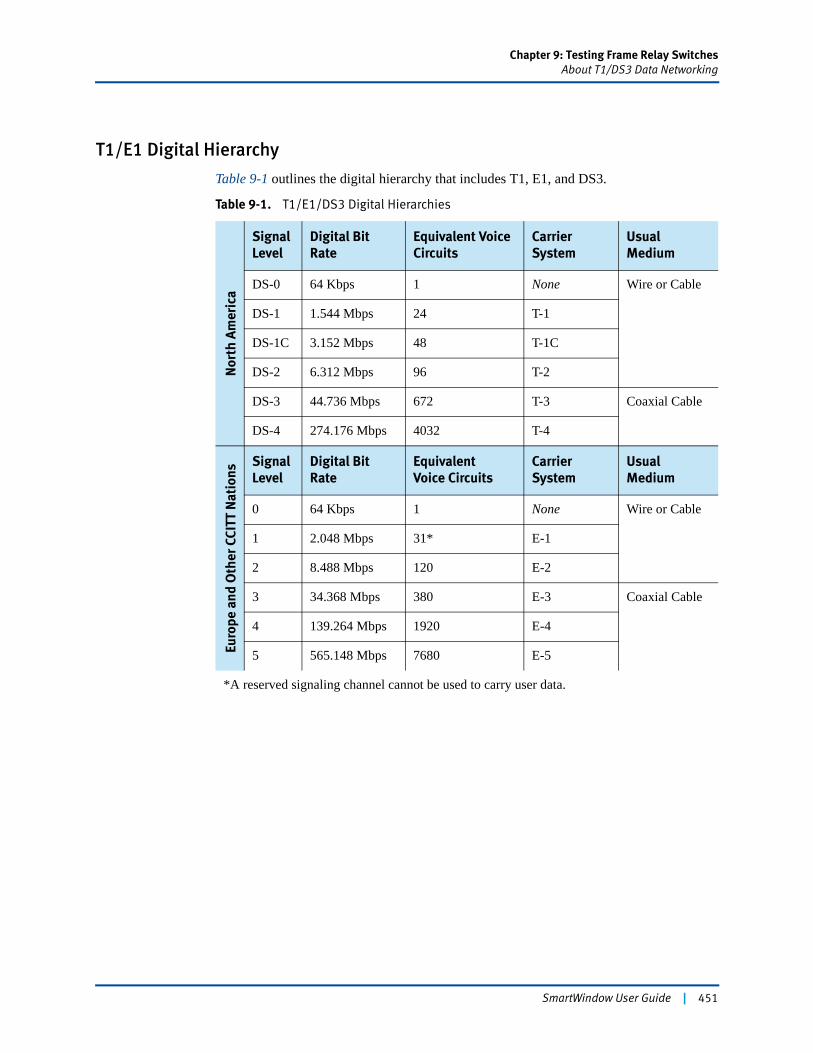
Chapter 9: Testing Frame Relay SwitchesAbout T1/DS3 Data Networking
T1/E1 Digital Hierarchy
Table 9-1 outlines the digital hierarchy that includes T1, E1, and DS3.
Table 9-1. T1/E1/DS3 Digital Hierarchies
Nor
th A
mer
ica
Signal Level
Digital Bit Rate
Equivalent Voice Circuits
Carrier System
Usual Medium
DS-0 64 Kbps 1 None Wire or Cable
DS-1 1.544 Mbps 24 T-1
DS-1C 3.152 Mbps 48 T-1C
DS-2 6.312 Mbps 96 T-2
DS-3 44.736 Mbps 672 T-3 Coaxial Cable
DS-4 274.176 Mbps 4032 T-4
Euro
pe a
nd O
ther
CCI
TT N
atio
ns
Signal Level
Digital Bit Rate
EquivalentVoice Circuits
Carrier System
Usual Medium
0 64 Kbps 1 None Wire or Cable
1 2.048 Mbps 31* E-1
2 8.488 Mbps 120 E-2
3 34.368 Mbps 380 E-3 Coaxial Cable
4 139.264 Mbps 1920 E-4
5 565.148 Mbps 7680 E-5
*A reserved signaling channel cannot be used to carry user data.
SmartWindow User Guide | 451

Chapter 9: Testing Frame Relay SwitchesCharacteristics of a Frame Relay Switch
Characteristics of a Frame Relay SwitchA frame relay switch is designed to support data in bursts and at high speeds in a bi-directional, conversational method of communication. The switch operates primarily at Layers 1 and 2 of the network model. It works by providing virtual circuit connections, in which dynamic links act like a pipe for moving traffic.
Service fees for frame relay connections are based on the Committed Information Rate (CIR), which is equal to the bandwidth available from one end to another. The minimum frame size is 32 bytes; the maximum is 8,191 bytes.
The local address for each link on a frame relay switch is the DLCI.
Types of Virtual Circuits
As noted above, a frame relay switch works by providing virtual circuit connections. There are three types of Virtual Circuits (VCs):
Switched (SVC)The SVC is similar to a voice connection made through the telephone network. When the network receives a connection request, it sets up a connection, data is sent, and then the connection is terminated.
Permanent (PVC)The PVC is a point-to-point connection that is similar to a leased data line. It is dedicated and used over long periods of time.
Multicast (MVC)The MVC is a connection between groups of users, who can use both SVCs and PVCs.
Note: Currently, SmartBits tests support only the PVC type of frame relay circuit.
452 | SmartWindow User Guide

Chapter 9: Testing Frame Relay SwitchesTesting for Throughput Capacity
Testing for Throughput CapacityUse the test procedures described in this chapter to determine the throughput capacity of a frame relay switch with a T1 (1.544 Mb) interface.
SmartWindow can be used to perform three basic tests in this area:. (See Table 9-2.)
Test Objectives with a Frame Relay Device
A frame relay device is designed to support bursty data at high speeds in a bi-directional, conversational communication mode. The switch operates primarily at Layers 1 and 2 of the network model. It works by providing virtual circuit connections, in which dynamic links act like a pipe for moving traffic.
The frame relay link consists of one or more virtual channels used for allocating dedicated bandwidth resources for multiplexed devices across the link. These logical channels are identified using the Data Link Connection Identifier (DLCI).
Note: The DLCI must be the same at the SmartCard port as it is for the DUT.
To perform this test:
The typical test sequence is as follows:1 Configure the PVC.2 Send increasingly heavy traffic streams.3 Observe the line rates at which DE frames are tagged and dropped.4 Check and troubleshoot the PVCs to confirm switch performance.
Test follow-up Configure multiple PVCs with varied frame rates to confirm the results of the single PVC.Verify that the link management protocol is working properly.
Table 9-2. Frame Relay Test Methodology
Test Used by Objective
1 End user To see that the switch does not set the DE bit before the CIR is exceeded.
2 Developer To see at which point the switch starts to drop frames, i.e., where frames received are less than frames transmitted.
3 Developer To see how well the Link Management Protocol (LMI Rev.1/ ITU Q.933 Annex A/ T1.617 Annex D) operates.
SmartWindow User Guide | 453
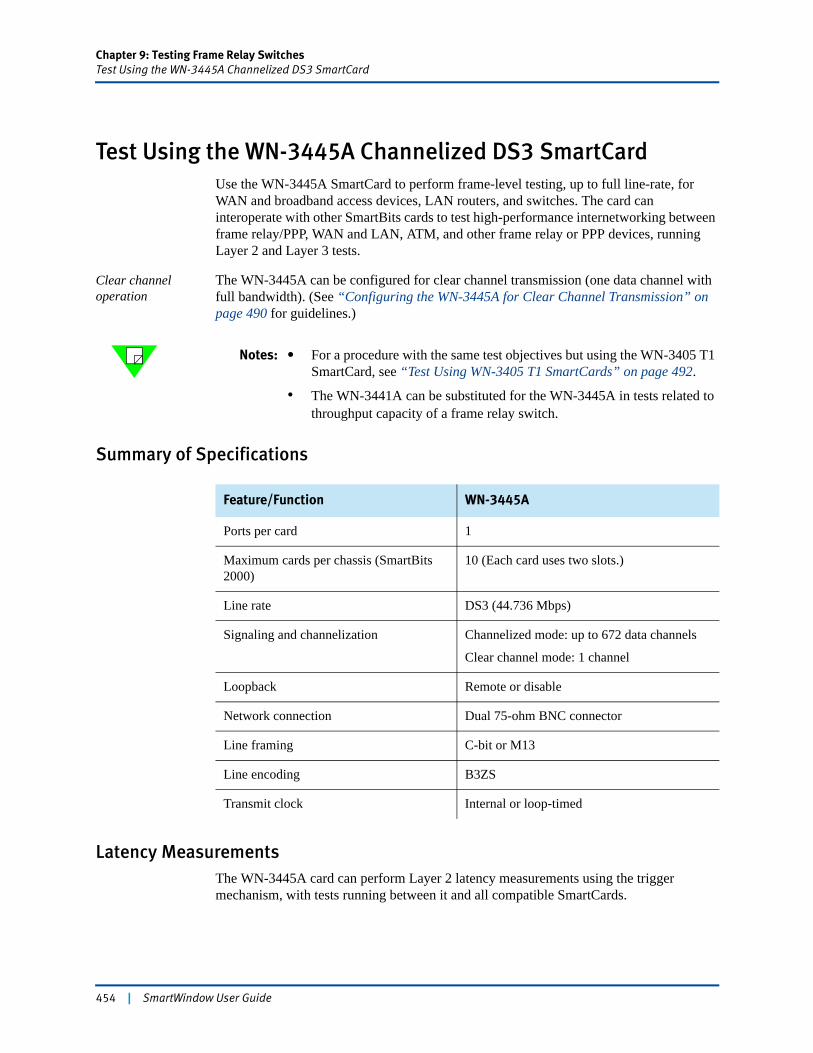
Chapter 9: Testing Frame Relay SwitchesTest Using the WN-3445A Channelized DS3 SmartCard
Test Using the WN-3445A Channelized DS3 SmartCardUse the WN-3445A SmartCard to perform frame-level testing, up to full line-rate, for WAN and broadband access devices, LAN routers, and switches. The card can interoperate with other SmartBits cards to test high-performance internetworking between frame relay/PPP, WAN and LAN, ATM, and other frame relay or PPP devices, running Layer 2 and Layer 3 tests.
Clear channel operation
The WN-3445A can be configured for clear channel transmission (one data channel with full bandwidth). (See “Configuring the WN-3445A for Clear Channel Transmission” on page 490 for guidelines.)
Notes: • For a procedure with the same test objectives but using the WN-3405 T1 SmartCard, see “Test Using WN-3405 T1 SmartCards” on page 492.
• The WN-3441A can be substituted for the WN-3445A in tests related to throughput capacity of a frame relay switch.
Summary of Specifications
Latency MeasurementsThe WN-3445A card can perform Layer 2 latency measurements using the trigger mechanism, with tests running between it and all compatible SmartCards.
Feature/Function WN-3445A
Ports per card 1
Maximum cards per chassis (SmartBits 2000)
10 (Each card uses two slots.)
Line rate DS3 (44.736 Mbps)
Signaling and channelization Channelized mode: up to 672 data channels
Clear channel mode: 1 channel
Loopback Remote or disable
Network connection Dual 75-ohm BNC connector
Line framing C-bit or M13
Line encoding B3ZS
Transmit clock Internal or loop-timed
454 | SmartWindow User Guide
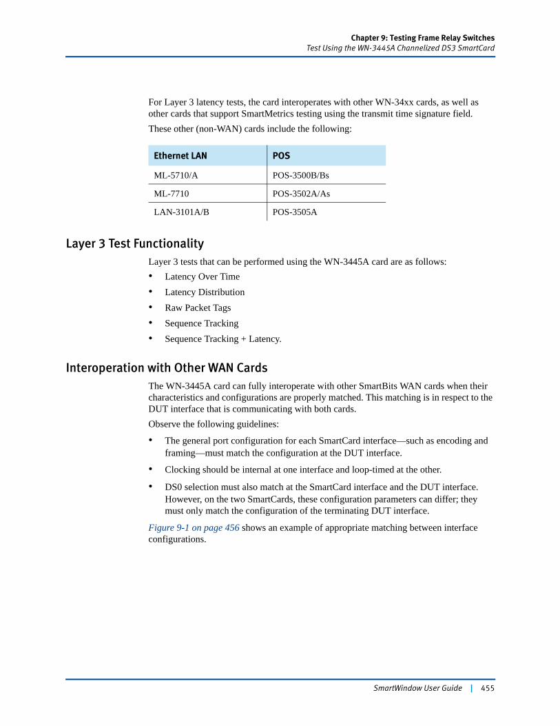
Chapter 9: Testing Frame Relay SwitchesTest Using the WN-3445A Channelized DS3 SmartCard
For Layer 3 latency tests, the card interoperates with other WN-34xx cards, as well as other cards that support SmartMetrics testing using the transmit time signature field.These other (non-WAN) cards include the following:
Layer 3 Test FunctionalityLayer 3 tests that can be performed using the WN-3445A card are as follows:• Latency Over Time• Latency Distribution• Raw Packet Tags• Sequence Tracking• Sequence Tracking + Latency.
Interoperation with Other WAN CardsThe WN-3445A card can fully interoperate with other SmartBits WAN cards when their characteristics and configurations are properly matched. This matching is in respect to the DUT interface that is communicating with both cards.Observe the following guidelines:
• The general port configuration for each SmartCard interface—such as encoding and framing—must match the configuration at the DUT interface.
• Clocking should be internal at one interface and loop-timed at the other.
• DS0 selection must also match at the SmartCard interface and the DUT interface. However, on the two SmartCards, these configuration parameters can differ; they must only match the configuration of the terminating DUT interface.
Figure 9-1 on page 456 shows an example of appropriate matching between interface configurations.
Ethernet LAN POS
ML-5710/A POS-3500B/Bs
ML-7710 POS-3502A/As
LAN-3101A/B POS-3505A
SmartWindow User Guide | 455
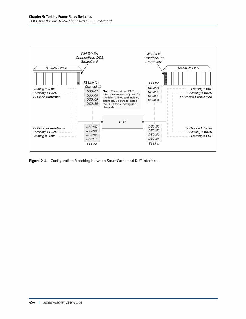
Chapter 9: Testing Frame Relay SwitchesTest Using the WN-3445A Channelized DS3 SmartCard
Figure 9-1. Configuration Matching between SmartCards and DUT Interfaces
WN-3445A WN-3415Fractional T1Channelized DS3
Framing = C-bitEncoding = B3ZSTx Clock = Internal
T1 Line (1)Channel #1DS0#07DS0#08DS0#09DS0#10
Framing = ESFEncoding = B8ZS
Tx Clock = Loop-timed
T1 LineDS0#01DS0#02DS0#03DS0#04
T1 Line
DS0#01DS0#02DS0#03DS0#04
SmartCard SmartCard
T1 Line
DS0#07DS0#08DS0#09DS0#10
DUT
Framing = C-bitEncoding = B3ZS
Framing = ESFEncoding = B8ZS
Tx Clock = InternalTx Clock = Loop-timed
SmartBits 2000 SmartBits 2000
Note: The card and DUT interface can be configured for multiple T1 lines and multiple channels. Be sure to match the DS0s for all configured channels.
456 | SmartWindow User Guide
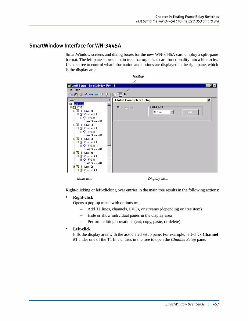
Chapter 9: Testing Frame Relay SwitchesTest Using the WN-3445A Channelized DS3 SmartCard
SmartWindow Interface for WN-3445A
SmartWindow screens and dialog boxes for the new WN-3445A card employ a split-pane format. The left pane shows a main tree that organizes card functionality into a hierarchy. Use the tree to control what information and options are displayed in the right pane, which is the display area.
Right-clicking or left-clicking over entries in the main tree results in the following actions:
• Right-clickOpens a pop-up menu with options to:
– Add T1 lines, channels, PVCs, or streams (depending on tree item)– Hide or show individual panes in the display area– Perform editing operations (cut, copy, paste, or delete).
• Left-clickFills the display area with the associated setup pane. For example, left-click Channel #1 under one of the T1 line entries in the tree to open the Channel Setup pane.
Toolbar
Display areaMain tree
SmartWindow User Guide | 457
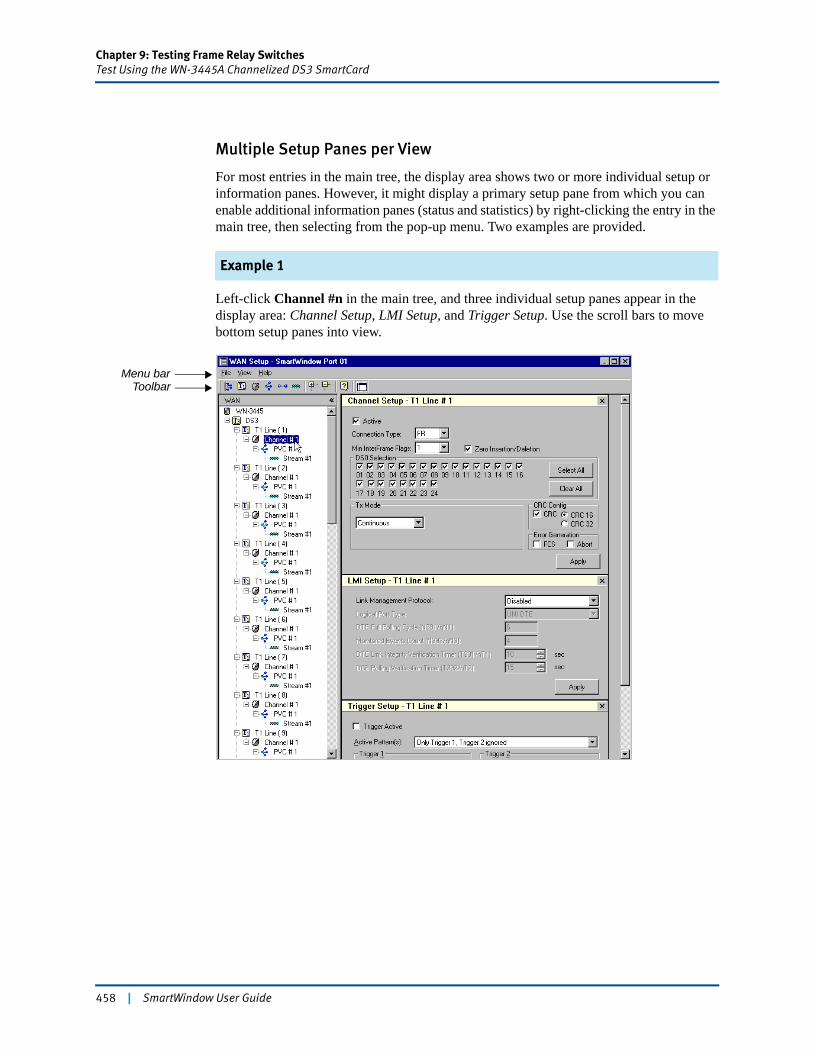
Chapter 9: Testing Frame Relay SwitchesTest Using the WN-3445A Channelized DS3 SmartCard
Multiple Setup Panes per View
For most entries in the main tree, the display area shows two or more individual setup or information panes. However, it might display a primary setup pane from which you can enable additional information panes (status and statistics) by right-clicking the entry in the main tree, then selecting from the pop-up menu. Two examples are provided.
Example 1
Left-click Channel #n in the main tree, and three individual setup panes appear in the display area: Channel Setup, LMI Setup, and Trigger Setup. Use the scroll bars to move bottom setup panes into view.
ToolbarMenu bar
458 | SmartWindow User Guide

Chapter 9: Testing Frame Relay SwitchesTest Using the WN-3445A Channelized DS3 SmartCard
Example 2
Left-click PVC#n in the main tree, and only the PVC Setup pane is shown. Add the PVC Statistics and PVC Status panes by right-clicking PVC#n in the main tree and enabling these views.
Toolbar and Menu Bar
A toolbar offers many of the options and controls that are available by using the main tree. All tool buttons self-identify when the cursor is held over them. The View option on the menu bar can be used to navigate among information and setup panes in the display area.
Using File > Update to Refresh SmartWindow Dialog Boxes
The File option on the WAN Setup menu bar includes an Update option. Use the Update option to refresh the information displayed in the SmartWindow interface. The card configuration is not updated. If you add channels in the WAN Setup window and need the new channels to appear in the SmartCounters window immediately, use the File > Update option.
Important: To update the card configuration completely, click the card image in Smart-Window and select Update this Port from the card menu. (For this option to appear, SmartWindow must be connected to the chassis, and the card must have been reserved.)
SmartWindow User Guide | 459

Chapter 9: Testing Frame Relay SwitchesTest Using the WN-3445A Channelized DS3 SmartCard
Using the View List to Modify Multiple Instances
The View option on the WAN Setup menu bar also provides a powerful way to modify a selected parameter in multiple instances of T1 lines, channels, PVCs, PPP connections, and streams.
When you select the View option and click any of these options, the display pane lists all the current instances. (See Figure 9-2 on page 461.) Select one or more instances in the following ways:
• Hold the left mouse button down and drag across entries.
• Hold the Shift key down to select a range of entries.
• Hold the Ctrl key down and click over multiple individual entries.
To modify a field value, right-click over the field and select from the pop-up menu. (See Figure 9-2 on page 461.)
Select Update This Port from the card menu to send the SmartWindow configuration to the card and activate the changes.
Select File > Update from the WAN Setup menu bar to refresh SmartWindow dialog boxes. This option does not update the card onboard configuration.
460 | SmartWindow User Guide
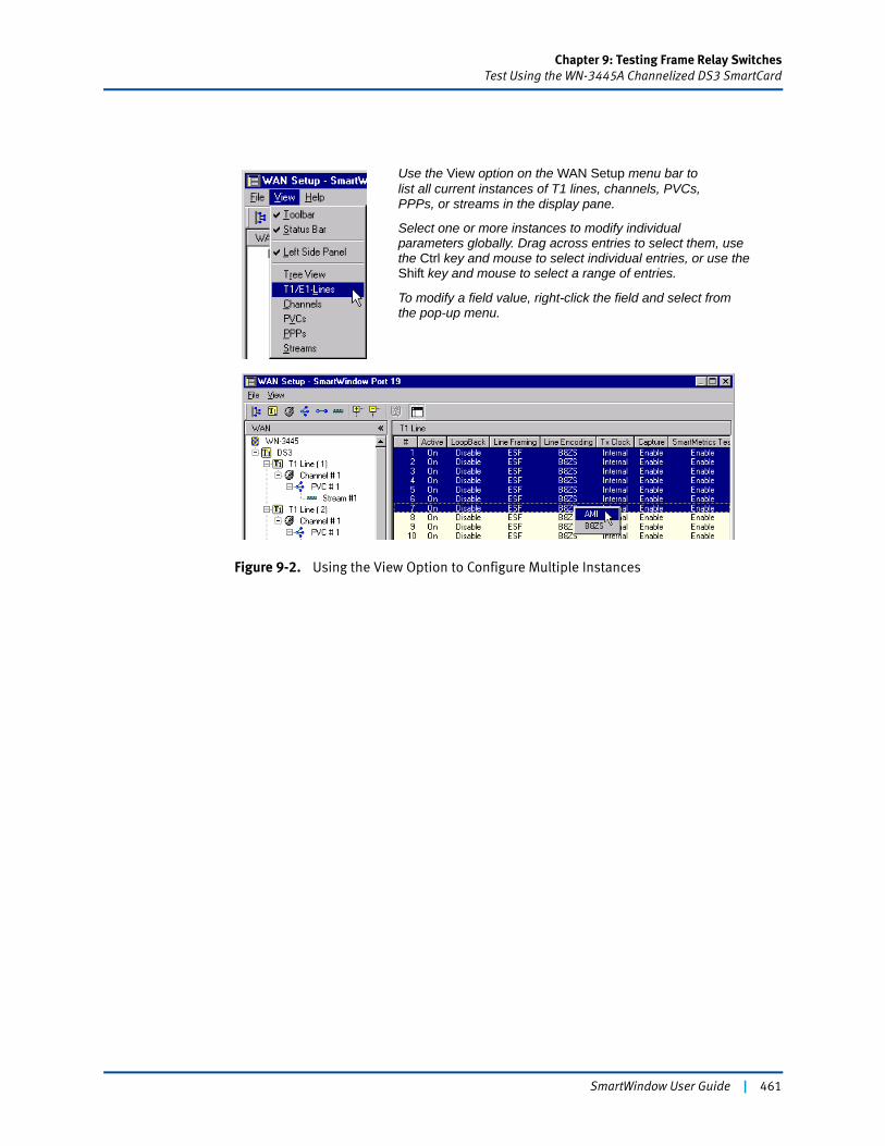
Chapter 9: Testing Frame Relay SwitchesTest Using the WN-3445A Channelized DS3 SmartCard
Figure 9-2. Using the View Option to Configure Multiple Instances
Use the View option on the WAN Setup menu bar tolist all current instances of T1 lines, channels, PVCs,PPPs, or streams in the display pane.
Select one or more instances to modify individualparameters globally. Drag across entries to select them, use
To modify a field value, right-click the field and select from
the Ctrl key and mouse to select individual entries, or use the Shift key and mouse to select a range of entries.
the pop-up menu.
SmartWindow User Guide | 461
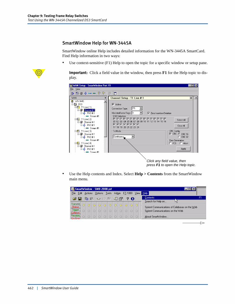
Chapter 9: Testing Frame Relay SwitchesTest Using the WN-3445A Channelized DS3 SmartCard
SmartWindow Help for WN-3445A
SmartWindow online Help includes detailed information for the WN-3445A SmartCard. Find Help information in two ways:
• Use context-sensitive (F1) Help to open the topic for a specific window or setup pane.
Important: Click a field value in the window, then press F1 for the Help topic to dis-play.
• Use the Help contents and Index. Select Help > Contents from the SmartWindow main menu.
Click any field value, thenpress F1 to open the Help topic.
462 | SmartWindow User Guide
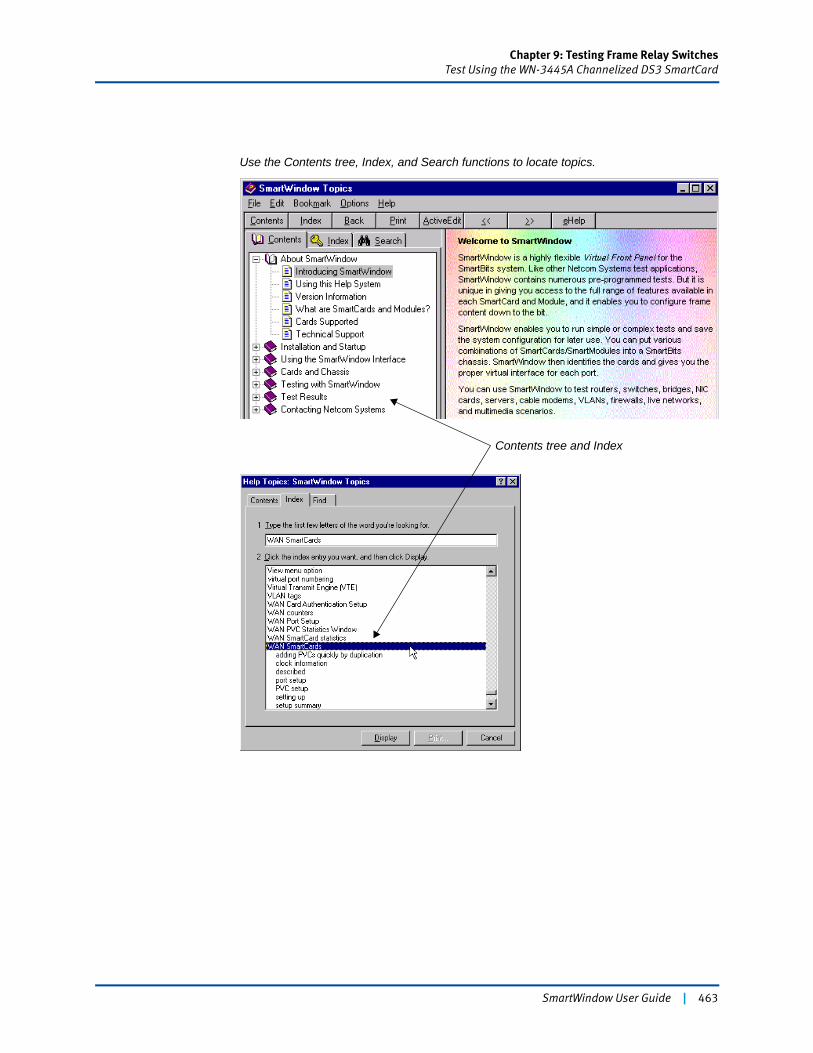
Chapter 9: Testing Frame Relay SwitchesTest Using the WN-3445A Channelized DS3 SmartCard
Contents tree and Index
Use the Contents tree, Index, and Search functions to locate topics.
SmartWindow User Guide | 463
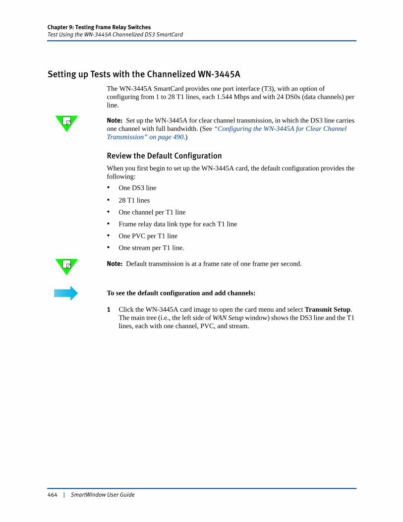
Chapter 9: Testing Frame Relay SwitchesTest Using the WN-3445A Channelized DS3 SmartCard
Setting up Tests with the Channelized WN-3445A
The WN-3445A SmartCard provides one port interface (T3), with an option of configuring from 1 to 28 T1 lines, each 1.544 Mbps and with 24 DS0s (data channels) per line.
Note: Set up the WN-3445A for clear channel transmission, in which the DS3 line carries one channel with full bandwidth. (See “Configuring the WN-3445A for Clear Channel Transmission” on page 490.)
Review the Default Configuration
When you first begin to set up the WN-3445A card, the default configuration provides the following:• One DS3 line
• 28 T1 lines
• One channel per T1 line
• Frame relay data link type for each T1 line
• One PVC per T1 line
• One stream per T1 line.
Note: Default transmission is at a frame rate of one frame per second.
To see the default configuration and add channels:
1 Click the WN-3445A card image to open the card menu and select Transmit Setup. The main tree (i.e., the left side of WAN Setup window) shows the DS3 line and the T1 lines, each with one channel, PVC, and stream.
464 | SmartWindow User Guide
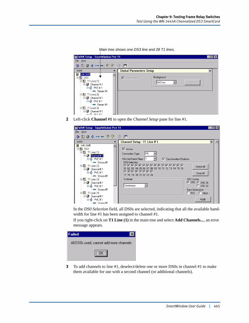
Chapter 9: Testing Frame Relay SwitchesTest Using the WN-3445A Channelized DS3 SmartCard
2 Left-click Channel #1 to open the Channel Setup pane for line #1.
In the DS0 Selection field, all DS0s are selected, indicating that all the available band-width for line #1 has been assigned to channel #1.If you right-click on T1 Line (1) in the main tree and select Add Channels..., an error message appears.
3 To add channels to line #1, deselect/delete one or more DS0s in channel #1 to make them available for use with a second channel (or additional channels).
Main tree shows one DS3 line and 28 T1 lines.
SmartWindow User Guide | 465
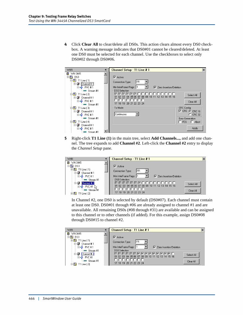
Chapter 9: Testing Frame Relay SwitchesTest Using the WN-3445A Channelized DS3 SmartCard
4 Click Clear All to clear/delete all DS0s. This action clears almost every DS0 check-box. A warning message indicates that DS0#01 cannot be cleared/deleted. At least one DS0 must be selected for each channel. Use the checkboxes to select only DS0#02 through DS0#06.
5 Right-click T1 Line (1) in the main tree, select Add Channels..., and add one chan-nel. The tree expands to add Channel #2. Left-click the Channel #2 entry to display the Channel Setup pane.
In Channel #2, one DS0 is selected by default (DS0#07). Each channel must contain at least one DS0. DS0#01 through #06 are already assigned to channel #1 and are unavailable. All remaining DS0s (#08 through #31) are available and can be assigned to this channel or to other channels (if added). For this example, assign DS0#08 through DS0#15 to channel #2.
466 | SmartWindow User Guide
Chapter 9: Testing Frame Relay SwitchesTest Using the WN-3445A Channelized DS3 SmartCard
Global Parameters in the Channel Setup Pane
Other fields in the Channel Setup pane set global parameters that apply to the channel and its assigned DS0s generally. (Refer to the online Help for detailed descriptions of these options.)
Data Link TypeThe channel Data Link Type field can be set to either FR (frame relay) or PPP. This selection determines how the next level in the main tree displays. (It shows PVC or PPP.) The related setup pane then displays options appropriate for the selected data link type.
Note: This document mainly uses a frame relay data link type in its examples, referencing setup of PVCs rather than PPPs. For details on the parameters that need to be configured if you set up PPP connections, refer to “PPP Setup Pane” or to the SmartWindow online Help.
PPP Setup Pane
To check or modify the PPP setup options, click PPP under Channel #1 in the main tree. Use this window to configure parameters for the Link Control Protocol (LCP) negotiation, such as IP Network Control Protocol (IP NCP), local and peer IP addresses, and authentication.
Transmitting frames with IP NCP disabled
The port can still transmit frames even when the IP Enabled checkbox is cleared, i.e., even when the IP NCP is disabled. This feature allows you to test protocol reject in PPP, if needed.
Note: When changes are complete, click the Apply button to start the PPP link actions that have been enabled. For example, if echo-request frames are enabled, the port begins sending them only when the Apply button is clicked.
SmartWindow User Guide | 467
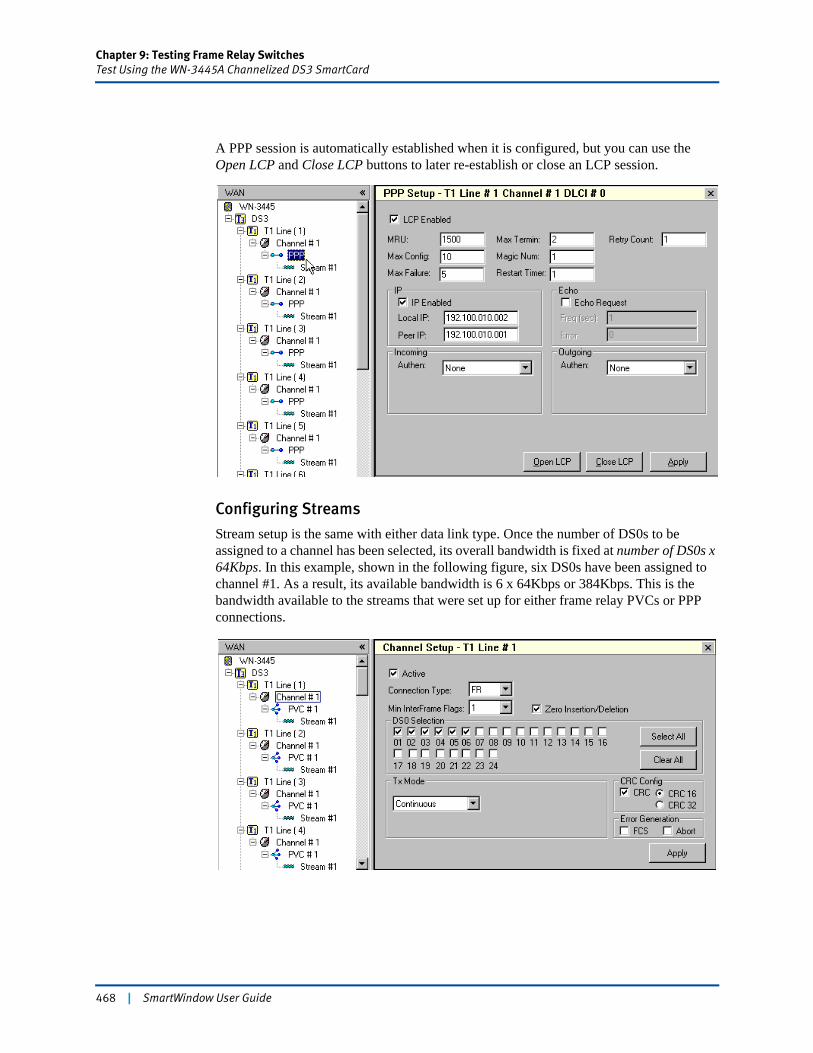
Chapter 9: Testing Frame Relay SwitchesTest Using the WN-3445A Channelized DS3 SmartCard
A PPP session is automatically established when it is configured, but you can use the Open LCP and Close LCP buttons to later re-establish or close an LCP session.
Configuring Streams
Stream setup is the same with either data link type. Once the number of DS0s to be assigned to a channel has been selected, its overall bandwidth is fixed at number of DS0s x 64Kbps. In this example, shown in the following figure, six DS0s have been assigned to channel #1. As a result, its available bandwidth is 6 x 64Kbps or 384Kbps. This is the bandwidth available to the streams that were set up for either frame relay PVCs or PPP connections.
468 | SmartWindow User Guide
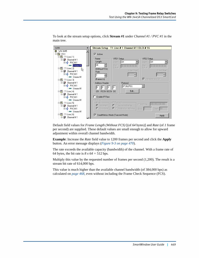
Chapter 9: Testing Frame Relay SwitchesTest Using the WN-3445A Channelized DS3 SmartCard
To look at the stream setup options, click Stream #1 under Channel #1 / PVC #1 in the main tree.
Default field values for Frame Length (Without FCS) [(of 64 bytes)] and Rate (of 1 frame per second) are supplied. These default values are small enough to allow for upward adjustment within overall channel bandwidth.
Example: Increase the Rate field value to 1200 frames per second and click the Apply button. An error message displays (Figure 9-3 on page 470).
The rate exceeds the available capacity (bandwidth) of the channel. With a frame rate of 64 bytes, the bit rate is 8 x 64 = 512 bps.
Multiply this value by the requested number of frames per second (1,200). The result is a stream bit rate of 614,000 bps.
This value is much higher than the available channel bandwidth (of 384,000 bps) as calculated on page 468, even without including the Frame Check Sequence (FCS).
SmartWindow User Guide | 469
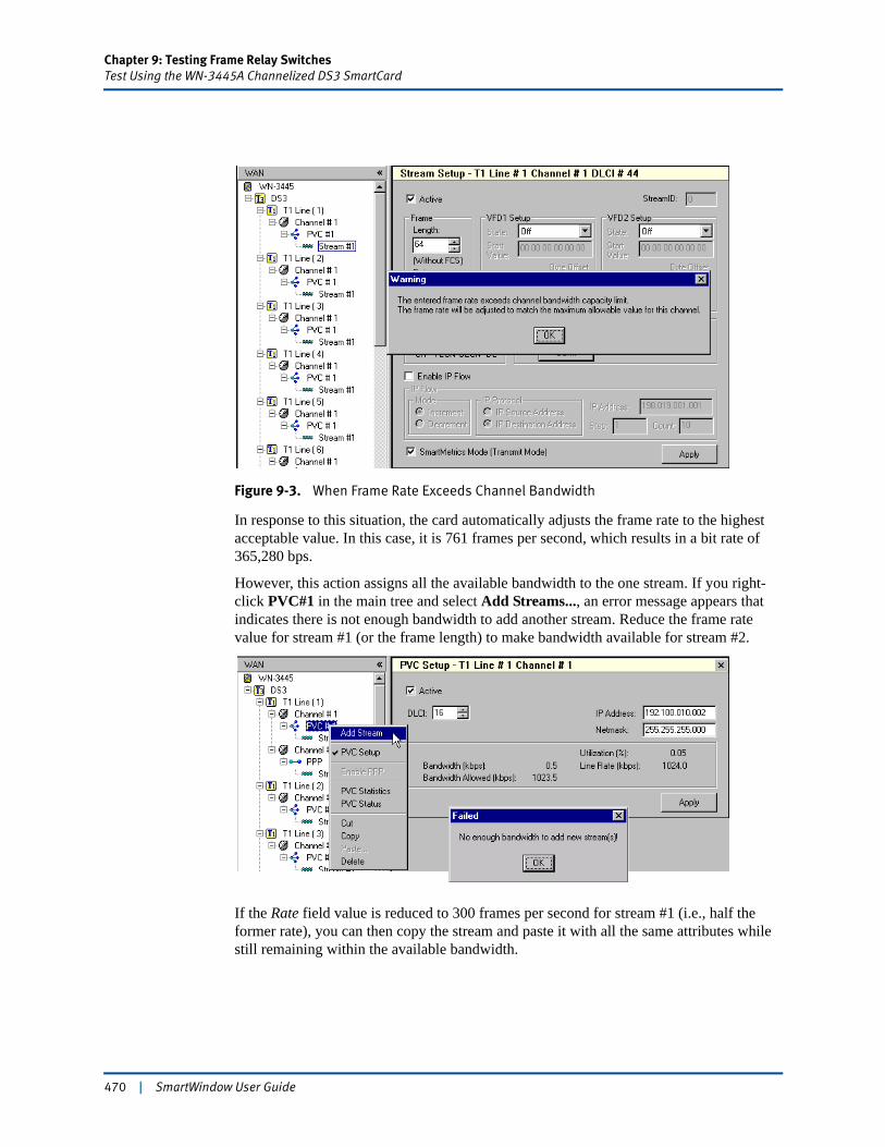
Chapter 9: Testing Frame Relay SwitchesTest Using the WN-3445A Channelized DS3 SmartCard
Figure 9-3. When Frame Rate Exceeds Channel Bandwidth
In response to this situation, the card automatically adjusts the frame rate to the highest acceptable value. In this case, it is 761 frames per second, which results in a bit rate of 365,280 bps.
However, this action assigns all the available bandwidth to the one stream. If you right-click PVC#1 in the main tree and select Add Streams..., an error message appears that indicates there is not enough bandwidth to add another stream. Reduce the frame rate value for stream #1 (or the frame length) to make bandwidth available for stream #2.
If the Rate field value is reduced to 300 frames per second for stream #1 (i.e., half the former rate), you can then copy the stream and paste it with all the same attributes while still remaining within the available bandwidth.
470 | SmartWindow User Guide
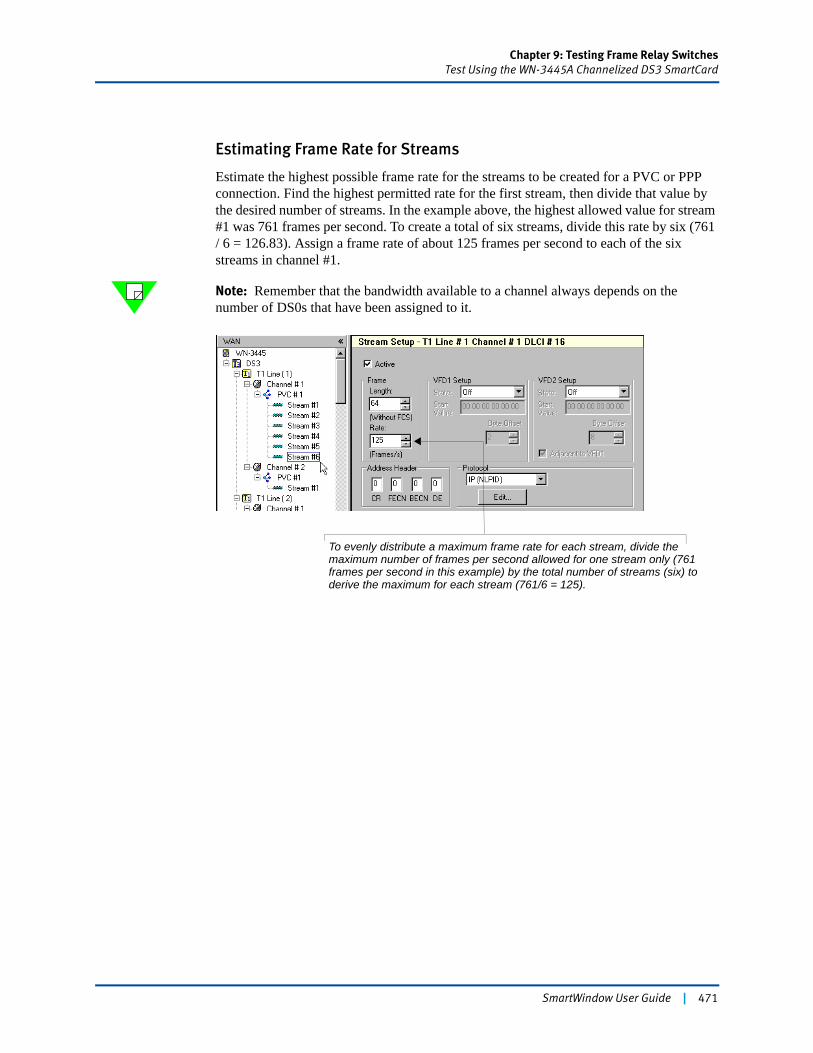
Chapter 9: Testing Frame Relay SwitchesTest Using the WN-3445A Channelized DS3 SmartCard
Estimating Frame Rate for Streams
Estimate the highest possible frame rate for the streams to be created for a PVC or PPP connection. Find the highest permitted rate for the first stream, then divide that value by the desired number of streams. In the example above, the highest allowed value for stream #1 was 761 frames per second. To create a total of six streams, divide this rate by six (761 / 6 = 126.83). Assign a frame rate of about 125 frames per second to each of the six streams in channel #1.
Note: Remember that the bandwidth available to a channel always depends on the number of DS0s that have been assigned to it.
To evenly distribute a maximum frame rate for each stream, divide the maximum number of frames per second allowed for one stream only (761 frames per second in this example) by the total number of streams (six) to derive the maximum for each stream (761/6 = 125).
SmartWindow User Guide | 471
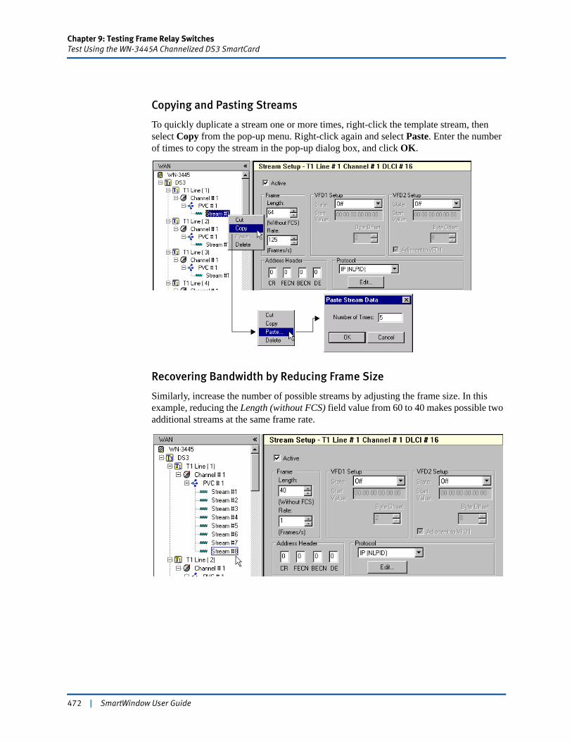
Chapter 9: Testing Frame Relay SwitchesTest Using the WN-3445A Channelized DS3 SmartCard
Copying and Pasting Streams
To quickly duplicate a stream one or more times, right-click the template stream, then select Copy from the pop-up menu. Right-click again and select Paste. Enter the number of times to copy the stream in the pop-up dialog box, and click OK.
Recovering Bandwidth by Reducing Frame Size
Similarly, increase the number of possible streams by adjusting the frame size. In this example, reducing the Length (without FCS) field value from 60 to 40 makes possible two additional streams at the same frame rate.
472 | SmartWindow User Guide
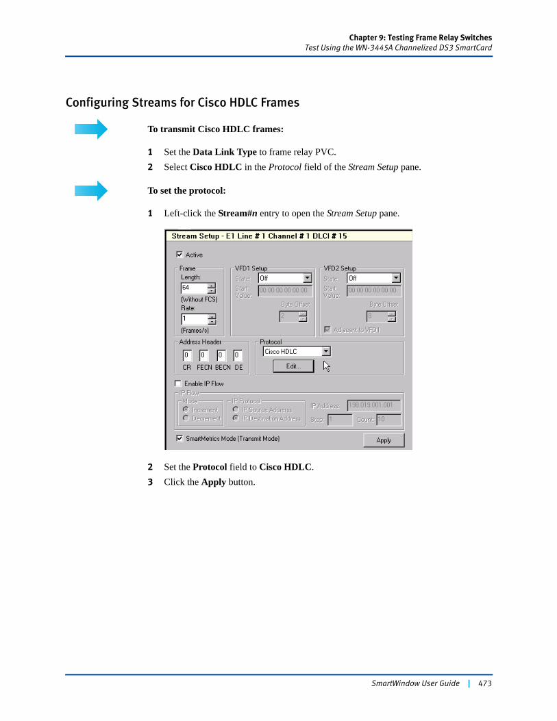
Chapter 9: Testing Frame Relay SwitchesTest Using the WN-3445A Channelized DS3 SmartCard
Configuring Streams for Cisco HDLC Frames
To transmit Cisco HDLC frames:
1 Set the Data Link Type to frame relay PVC.2 Select Cisco HDLC in the Protocol field of the Stream Setup pane.
To set the protocol:
1 Left-click the Stream#n entry to open the Stream Setup pane.
2 Set the Protocol field to Cisco HDLC.3 Click the Apply button.
SmartWindow User Guide | 473
Chapter 9: Testing Frame Relay SwitchesTest Using the WN-3445A Channelized DS3 SmartCard
Configure the DUTThe DUT is typically configured as the Data Circuit-terminating Equipment (DCE). As a minimum, its configuration includes setting values for the following parameters:
• Line rate
• Committed Information Rate (CIR)
• Flow control mechanisms: FECN, BECN, and DE
• Link Management Protocol: LMI, Q.933 Annex A, or T1.617 Annex D.
These DUT configuration settings must be duplicated in the SmartBits system. If the settings are not duplicated, the DUT may not accept SmartBits traffic during the test.
Set up Physical Connections
Once the DUT configuration is completed, set up the physical connections. In this example, two WAN cards are used. A DS3 port is configured on one card as the transmit port, and another DS3 port is configured on the other card as the receive port.
To set up the physical connection:
1 Install a WN-3445A SmartCard in the SmartBits 2000 chassis.2 Attach a connecting cable between the BNC port interface connector on each Smart-
Card and ports on the DUT.
474 | SmartWindow User Guide
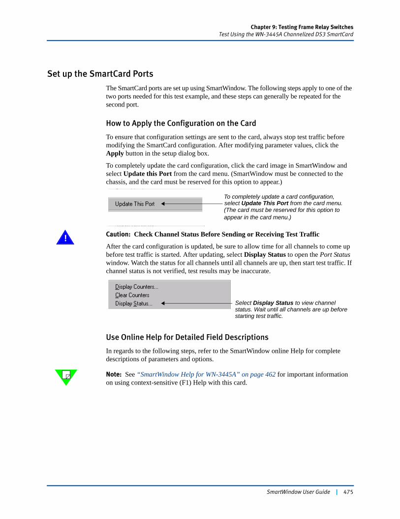
Chapter 9: Testing Frame Relay SwitchesTest Using the WN-3445A Channelized DS3 SmartCard
Set up the SmartCard Ports
The SmartCard ports are set up using SmartWindow. The following steps apply to one of the two ports needed for this test example, and these steps can generally be repeated for the second port.
How to Apply the Configuration on the Card
To ensure that configuration settings are sent to the card, always stop test traffic before modifying the SmartCard configuration. After modifying parameter values, click the Apply button in the setup dialog box.
To completely update the card configuration, click the card image in SmartWindow and select Update this Port from the card menu. (SmartWindow must be connected to the chassis, and the card must be reserved for this option to appear.)
! Caution: Check Channel Status Before Sending or Receiving Test Traffic
After the card configuration is updated, be sure to allow time for all channels to come up before test traffic is started. After updating, select Display Status to open the Port Status window. Watch the status for all channels until all channels are up, then start test traffic. If channel status is not verified, test results may be inaccurate.
Use Online Help for Detailed Field Descriptions
In regards to the following steps, refer to the SmartWindow online Help for complete descriptions of parameters and options.
Note: See “SmartWindow Help for WN-3445A” on page 462 for important information on using context-sensitive (F1) Help with this card.
To completely update a card configuration,select Update This Port from the card menu.(The card must be reserved for this option toappear in the card menu.)
Select Display Status to view channel status. Wait until all channels are up before starting test traffic.
SmartWindow User Guide | 475
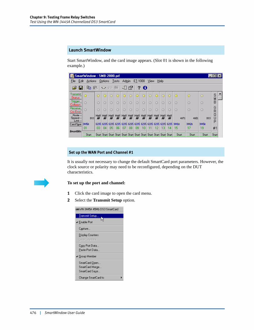
Chapter 9: Testing Frame Relay SwitchesTest Using the WN-3445A Channelized DS3 SmartCard
Launch SmartWindow
Start SmartWindow, and the card image appears. (Slot 01 is shown in the following example.)
Set up the WAN Port and Channel #1
It is usually not necessary to change the default SmartCard port parameters. However, the clock source or polarity may need to be reconfigured, depending on the DUT characteristics.
To set up the port and channel:
1 Click the card image to open the card menu.2 Select the Transmit Setup option.
476 | SmartWindow User Guide
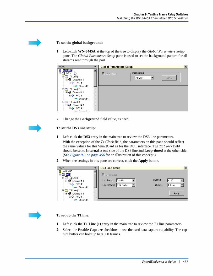
Chapter 9: Testing Frame Relay SwitchesTest Using the WN-3445A Channelized DS3 SmartCard
To set the global background:
1 Left-click WN-3445A at the top of the tree to display the Global Parameters Setup pane. The Global Parameters Setup pane is used to set the background pattern for all streams sent through the port.
2 Change the Background field value, as need.
To set the DS3 line setup:
1 Left-click the DS3 entry in the main tree to review the DS3 line parameters.With the exception of the Tx Clock field, the parameters on this pane should reflect the same values for this SmartCard as for the DUT interface. The Tx Clock field should be set to Internal at one side of the DS3 line and Loop-timed at the other side. (See Figure 9-1 on page 456 for an illustration of this concept.)
2 When the settings in this pane are correct, click the Apply button.
To set up the T1 line:
1 Left-click the T1 Line (1) entry in the main tree to review the T1 line parameters.2 Select the Enable Capture checkbox to use the card data capture capability. The cap-
ture buffer can hold up to 8,000 frames.
SmartWindow User Guide | 477
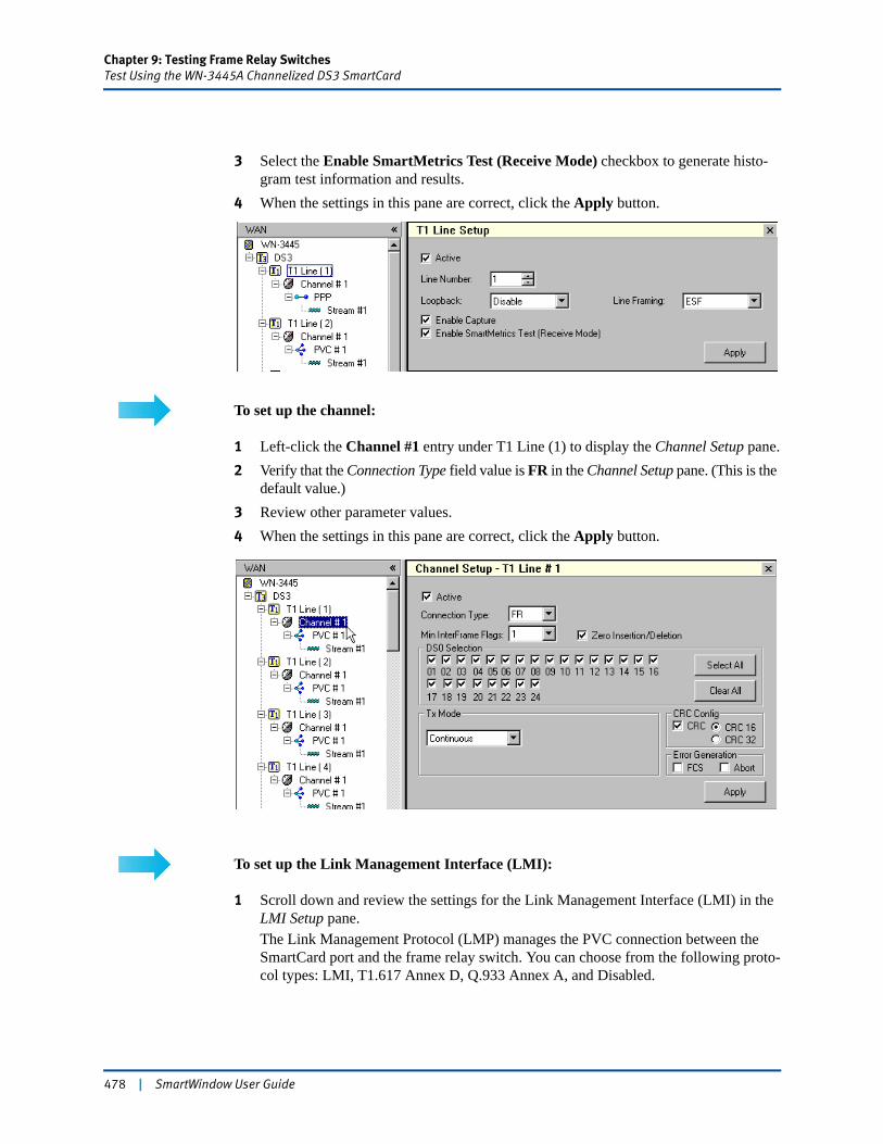
Chapter 9: Testing Frame Relay SwitchesTest Using the WN-3445A Channelized DS3 SmartCard
3 Select the Enable SmartMetrics Test (Receive Mode) checkbox to generate histo-gram test information and results.
4 When the settings in this pane are correct, click the Apply button.
To set up the channel:
1 Left-click the Channel #1 entry under T1 Line (1) to display the Channel Setup pane.2 Verify that the Connection Type field value is FR in the Channel Setup pane. (This is the
default value.)3 Review other parameter values.4 When the settings in this pane are correct, click the Apply button.
To set up the Link Management Interface (LMI):
1 Scroll down and review the settings for the Link Management Interface (LMI) in the LMI Setup pane. The Link Management Protocol (LMP) manages the PVC connection between the SmartCard port and the frame relay switch. You can choose from the following proto-col types: LMI, T1.617 Annex D, Q.933 Annex A, and Disabled.
478 | SmartWindow User Guide
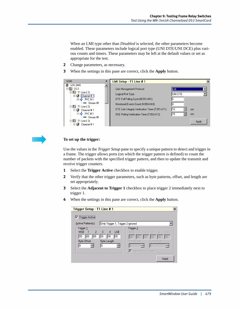
Chapter 9: Testing Frame Relay SwitchesTest Using the WN-3445A Channelized DS3 SmartCard
When an LMI type other than Disabled is selected, the other parameters become enabled. These parameters include logical port type (UNI DTE/UNI DCE) plus vari-ous counts and timers. These parameters may be left at the default values or set as appropriate for the test.
2 Change parameters, as necessary.3 When the settings in this pane are correct, click the Apply button.
To set up the trigger:
Use the values in the Trigger Setup pane to specify a unique pattern to detect and trigger in a frame. The trigger allows ports (on which the trigger pattern is defined) to count the number of packets with the specified trigger pattern, and then to update the transmit and receive trigger counters.1 Select the Trigger Active checkbox to enable trigger.2 Verify that the other trigger parameters, such as byte patterns, offset, and length are
set appropriately.3 Select the Adjacent to Trigger 1 checkbox to place trigger 2 immediately next to
trigger 1.4 When the settings in this pane are correct, click the Apply button.
SmartWindow User Guide | 479
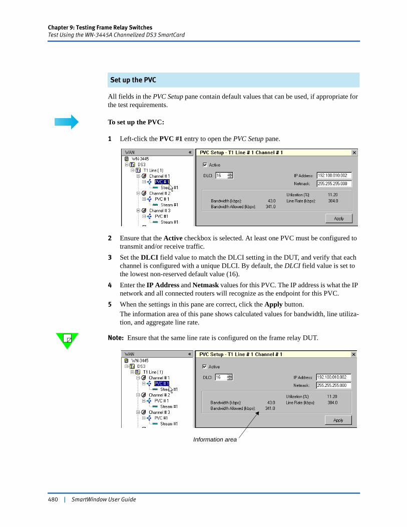
Chapter 9: Testing Frame Relay SwitchesTest Using the WN-3445A Channelized DS3 SmartCard
Set up the PVC
All fields in the PVC Setup pane contain default values that can be used, if appropriate for the test requirements.
To set up the PVC:
1 Left-click the PVC #1 entry to open the PVC Setup pane.
2 Ensure that the Active checkbox is selected. At least one PVC must be configured to transmit and/or receive traffic.
3 Set the DLCI field value to match the DLCI setting in the DUT, and verify that each channel is configured with a unique DLCI. By default, the DLCI field value is set to the lowest non-reserved default value (16).
4 Enter the IP Address and Netmask values for this PVC. The IP address is what the IP network and all connected routers will recognize as the endpoint for this PVC.
5 When the settings in this pane are correct, click the Apply button.The information area of this pane shows calculated values for bandwidth, line utiliza-tion, and aggregate line rate.
Note: Ensure that the same line rate is configured on the frame relay DUT.
Information area
480 | SmartWindow User Guide
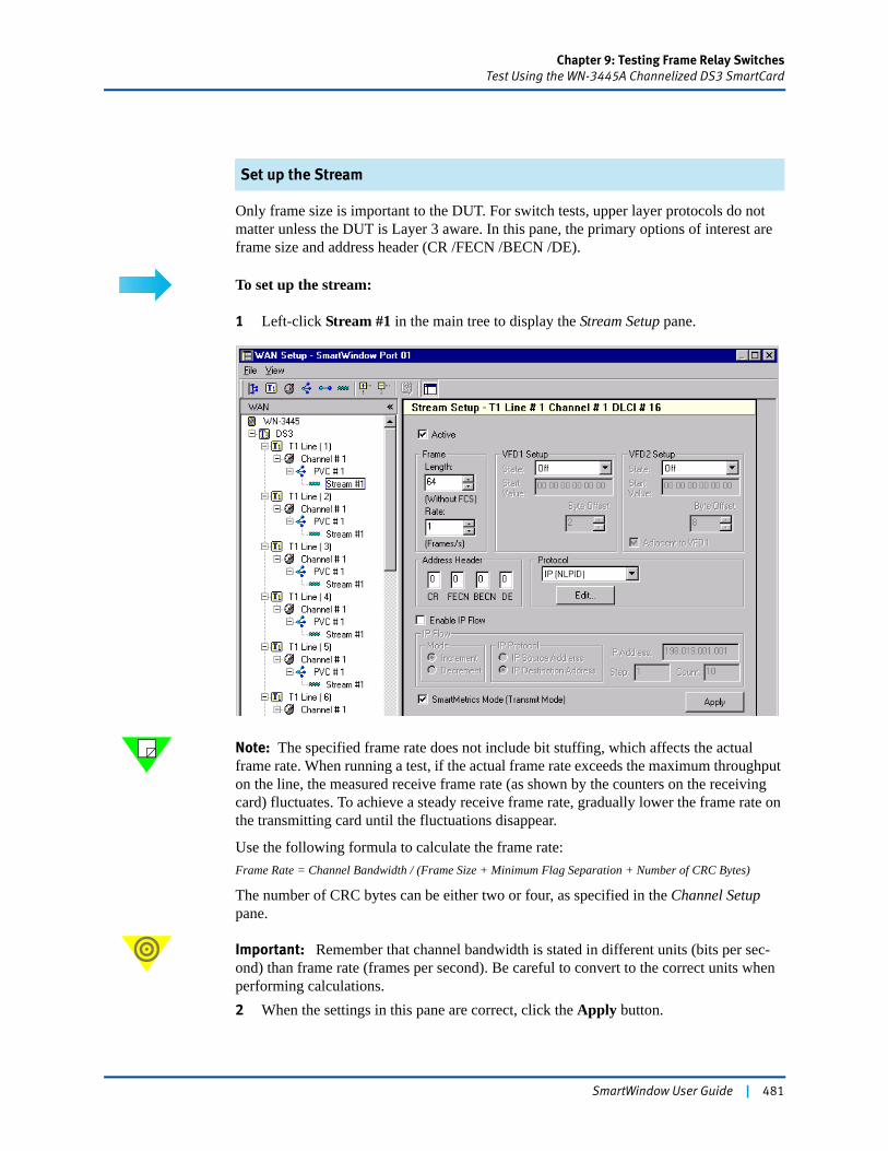
Chapter 9: Testing Frame Relay SwitchesTest Using the WN-3445A Channelized DS3 SmartCard
Set up the Stream
Only frame size is important to the DUT. For switch tests, upper layer protocols do not matter unless the DUT is Layer 3 aware. In this pane, the primary options of interest are frame size and address header (CR /FECN /BECN /DE).
To set up the stream:
1 Left-click Stream #1 in the main tree to display the Stream Setup pane.
Note: The specified frame rate does not include bit stuffing, which affects the actual frame rate. When running a test, if the actual frame rate exceeds the maximum throughput on the line, the measured receive frame rate (as shown by the counters on the receiving card) fluctuates. To achieve a steady receive frame rate, gradually lower the frame rate on the transmitting card until the fluctuations disappear.
Use the following formula to calculate the frame rate:Frame Rate = Channel Bandwidth / (Frame Size + Minimum Flag Separation + Number of CRC Bytes)
The number of CRC bytes can be either two or four, as specified in the Channel Setup pane.
Important: Remember that channel bandwidth is stated in different units (bits per sec-ond) than frame rate (frames per second). Be careful to convert to the correct units when performing calculations.2 When the settings in this pane are correct, click the Apply button.
SmartWindow User Guide | 481
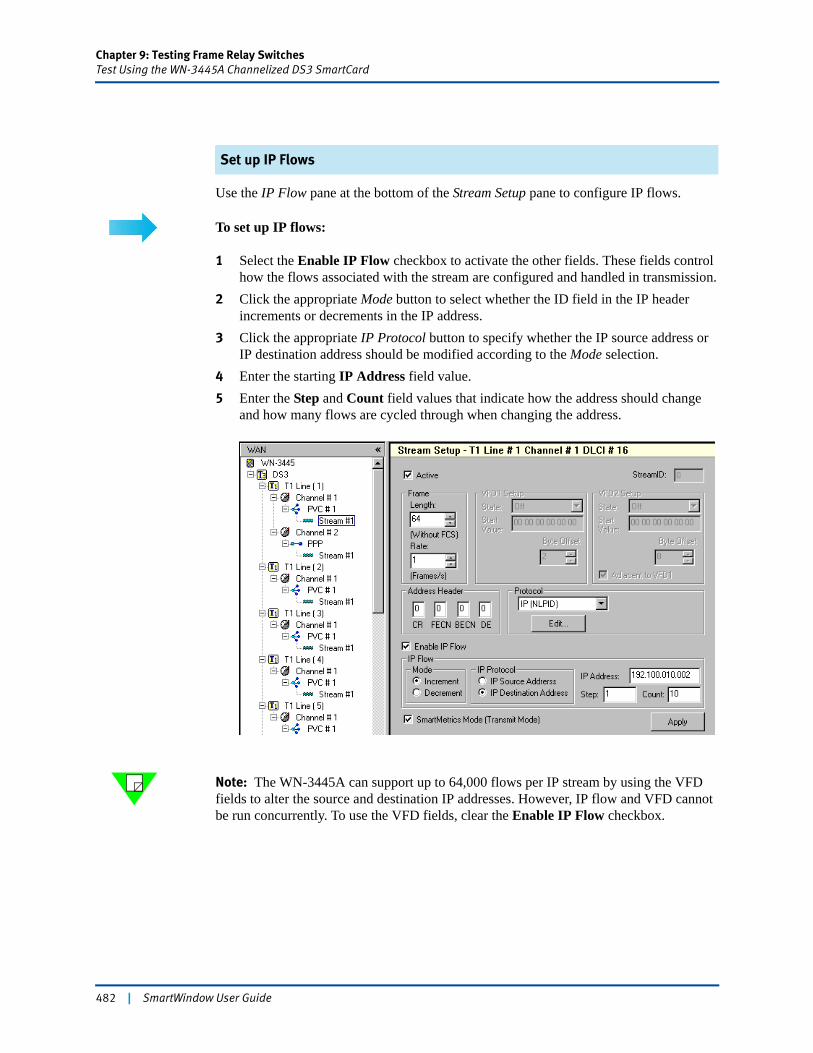
Chapter 9: Testing Frame Relay SwitchesTest Using the WN-3445A Channelized DS3 SmartCard
Set up IP Flows
Use the IP Flow pane at the bottom of the Stream Setup pane to configure IP flows.
To set up IP flows:
1 Select the Enable IP Flow checkbox to activate the other fields. These fields control how the flows associated with the stream are configured and handled in transmission.
2 Click the appropriate Mode button to select whether the ID field in the IP header increments or decrements in the IP address.
3 Click the appropriate IP Protocol button to specify whether the IP source address or IP destination address should be modified according to the Mode selection.
4 Enter the starting IP Address field value.5 Enter the Step and Count field values that indicate how the address should change
and how many flows are cycled through when changing the address.
Note: The WN-3445A can support up to 64,000 flows per IP stream by using the VFD fields to alter the source and destination IP addresses. However, IP flow and VFD cannot be run concurrently. To use the VFD fields, clear the Enable IP Flow checkbox.
482 | SmartWindow User Guide
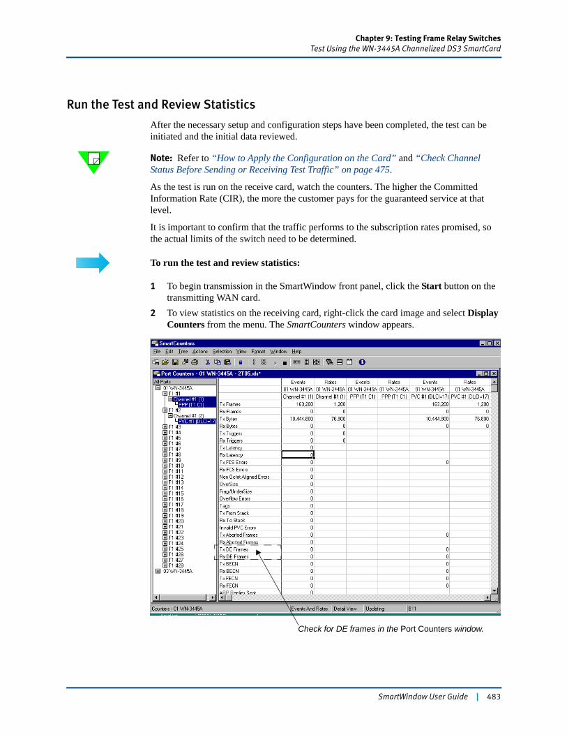
Chapter 9: Testing Frame Relay SwitchesTest Using the WN-3445A Channelized DS3 SmartCard
Run the Test and Review Statistics
After the necessary setup and configuration steps have been completed, the test can be initiated and the initial data reviewed.
Note: Refer to “How to Apply the Configuration on the Card” and “Check Channel Status Before Sending or Receiving Test Traffic” on page 475.
As the test is run on the receive card, watch the counters. The higher the Committed Information Rate (CIR), the more the customer pays for the guaranteed service at that level.
It is important to confirm that the traffic performs to the subscription rates promised, so the actual limits of the switch need to be determined.
To run the test and review statistics:
1 To begin transmission in the SmartWindow front panel, click the Start button on the transmitting WAN card.
2 To view statistics on the receiving card, right-click the card image and select Display Counters from the menu. The SmartCounters window appears.
Check for DE frames in the Port Counters window.
SmartWindow User Guide | 483
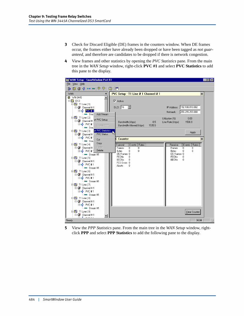
Chapter 9: Testing Frame Relay SwitchesTest Using the WN-3445A Channelized DS3 SmartCard
3 Check for Discard Eligible (DE) frames in the counters window. When DE frames occur, the frames either have already been dropped or have been tagged as not guar-anteed, and therefore are candidates to be dropped if there is network congestion.
4 View frames and other statistics by opening the PVC Statistics pane. From the main tree in the WAN Setup window, right-click PVC #1 and select PVC Statistics to add this pane to the display.
5 View the PPP Statistics pane. From the main tree in the WAN Setup window, right-click PPP and select PPP Statistics to add the following pane to the display.
484 | SmartWindow User Guide
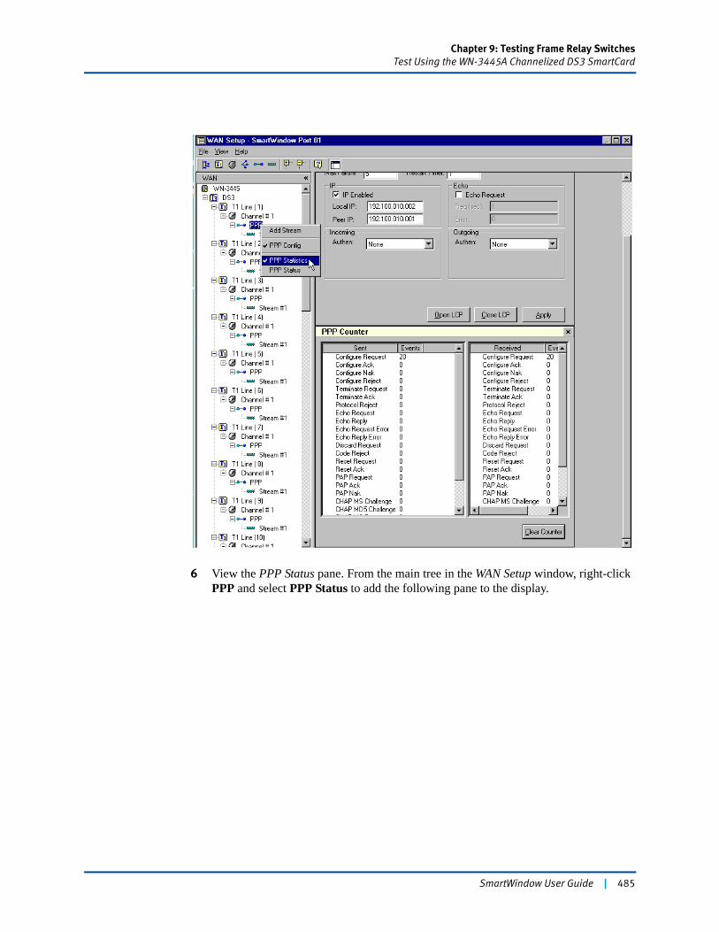
Chapter 9: Testing Frame Relay SwitchesTest Using the WN-3445A Channelized DS3 SmartCard
6 View the PPP Status pane. From the main tree in the WAN Setup window, right-click PPP and select PPP Status to add the following pane to the display.
SmartWindow User Guide | 485
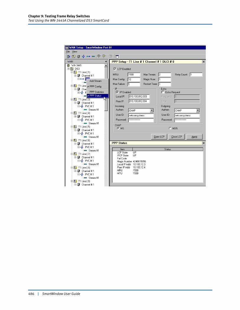
Chapter 9: Testing Frame Relay SwitchesTest Using the WN-3445A Channelized DS3 SmartCard
486 | SmartWindow User Guide

Chapter 9: Testing Frame Relay SwitchesTest Using the WN-3445A Channelized DS3 SmartCard
Using SmartCounters
Use SmartCounters to save statistics and to see data on a specific port.
To use SmartCounters:
1 Choose Actions > SmartCounters.2 Select File > New to open a new counter window.3 To save the statistical data available at that moment for the highlighted port, choose
File > Save As from the SmartCounters menu. The data is saved to an Excel spread-sheet (see the figure below).
4 Choose View > Counter Only to see only the data on a specific port.
Note: The WN-3445A can require additional time to clear counters and display new counts. Allow from 10 to 15 seconds.
For complete information on SmartCounters, refer to “Set up IGMP for SmartBits 600x/6000x Modules” on page 120 in Chapter 5, “Advanced Operational Theory.”
SmartWindow User Guide | 487
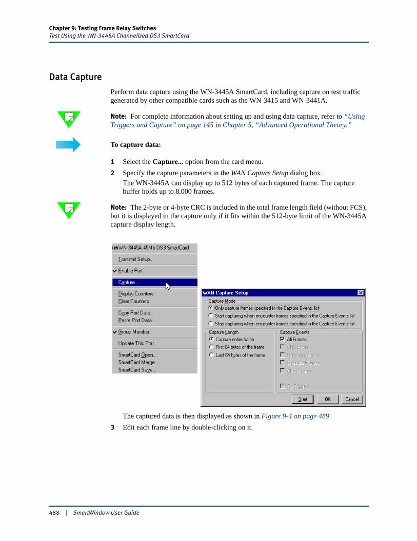
Chapter 9: Testing Frame Relay SwitchesTest Using the WN-3445A Channelized DS3 SmartCard
Data Capture
Perform data capture using the WN-3445A SmartCard, including capture on test traffic generated by other compatible cards such as the WN-3415 and WN-3441A.
Note: For complete information about setting up and using data capture, refer to “Using Triggers and Capture” on page 145 in Chapter 5, “Advanced Operational Theory.”
To capture data:
1 Select the Capture... option from the card menu.2 Specify the capture parameters in the WAN Capture Setup dialog box.
The WN-3445A can display up to 512 bytes of each captured frame. The capture buffer holds up to 8,000 frames.
Note: The 2-byte or 4-byte CRC is included in the total frame length field (without FCS), but it is displayed in the capture only if it fits within the 512-byte limit of the WN-3445A capture display length.
The captured data is then displayed as shown in Figure 9-4 on page 489.3 Edit each frame line by double-clicking on it.
488 | SmartWindow User Guide
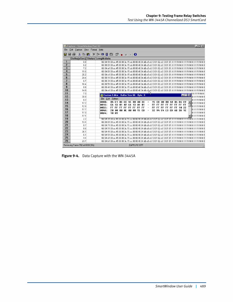
Chapter 9: Testing Frame Relay SwitchesTest Using the WN-3445A Channelized DS3 SmartCard
Figure 9-4. Data Capture with the WN-3445A
SmartWindow User Guide | 489

Chapter 9: Testing Frame Relay SwitchesTest Using the WN-3445A Channelized DS3 SmartCard
Configuring the WN-3445A for Clear Channel Transmission
Set up the WN-3445A DS3 SmartCard for clear channel transmission. The DS3 line (port) then carries one channel, which may carry multiple frame relay PVCs or one PPP connection. There is no T1 line in clear channel mode.
To enable clear channel:
Important: When the card mode is changed from channelized to clear channel, any on-going channelized configuration data is lost. Be careful to save the channelized configura-tion before enabling clear channel.1 Click the card image to open the card menu2 Select the Clear Channel option (Figure 9-5).
Figure 9-5. Enabling Clear Channel Operation
3 Select the Transmit Setup option from the card menu.The WAN Setup tree contains just one channel.
4 Select the channel, and use the Channel Setup pane to configure the data link type as frame relay or PPP.
490 | SmartWindow User Guide
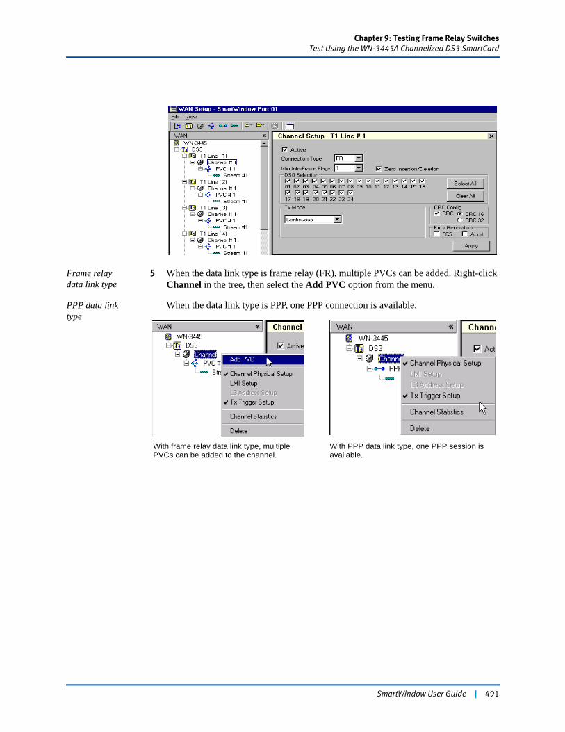
Chapter 9: Testing Frame Relay SwitchesTest Using the WN-3445A Channelized DS3 SmartCard
Frame relaydata link type
5 When the data link type is frame relay (FR), multiple PVCs can be added. Right-click Channel in the tree, then select the Add PVC option from the menu.
PPP data link type
When the data link type is PPP, one PPP connection is available.
With frame relay data link type, multiple PVCs can be added to the channel.
With PPP data link type, one PPP session is available.
SmartWindow User Guide | 491

Chapter 9: Testing Frame Relay SwitchesTest Using WN-3405 T1 SmartCards
Test Using WN-3405 T1 SmartCardsThis section outlines the procedure for frame relay throughput testing using the WN-3405 fractional T1 SmartCard.
Notes: • See “Test Using the WN-3445A Channelized DS3 SmartCard” on page 454 for a procedure with the same test objectives but using the WN-3445A Channelized DS3 SmartCard.
• The WN-3415, WN-3420, or WN-3441A can be substituted for the WN-3405 when testing the throughput capacity of a frame relay switch.
Configure the Switch as DCEFirst, configure the frame relay switch. It is typically configured as the Data Circuit-terminating Equipment (DCE). As a minimum, its configuration includes setting values for the following parameters:
• Line rate
• Committed Information Rate (CIR)
• Quality of Service parameters: FECN, BECN or DE
• Link Management Protocol: LMI, Annex A, or Annex D.
These configuration settings in the DUT must be duplicated in the SmartBits system. If the settings are not duplicated, the switch may not accept SmartBits traffic during the test.
Important: SmartWindow does not support split-clocking. Although SmartWindow does auto-detect, in DTE mode the line rate must be specified and must match the line rate of the DUT.
492 | SmartWindow User Guide

Chapter 9: Testing Frame Relay SwitchesTest Using WN-3405 T1 SmartCards
Set up Physical Connections
Once the switch configuration has been completed, set up the physical connections. This test example assumes a two-port test, although SmartBits can accommodate tests with more than two ports if necessary. In this example, configure port 14 as the transmit port and port 15 as the receive port.
This example uses the WN-3405 SmartCard. By default, it is set for Data Terminal Equipment (DTE).
To set up the physical connection:
1 Install two WN-3405 SmartCards in the SmartBits chassis. Each WN-3405 supports 128 PVCs per port.
2 Connect the provided V.35 Winchester cable between one WN-3405 SmartCard and to the switch to be tested. (An additional cable might be needed, depending on the type of connector on the switch. This cable can be obtained from the switch manufac-turer.)
Set up the WAN Cards
Now set up the WAN cards using SmartWindow.
Note: Confirm that SmartWindow is installed on a PC that is connected to SmartBits. See “Installing SmartWindow” on page 28 for additional information.
Launch SmartWindow
To start SmartWindow:
1 Click the SmartWindow icon.2 Confirm the card interface by right-clicking the card (V.35). The card image shows
DTE ext.
SmartWindow User Guide | 493
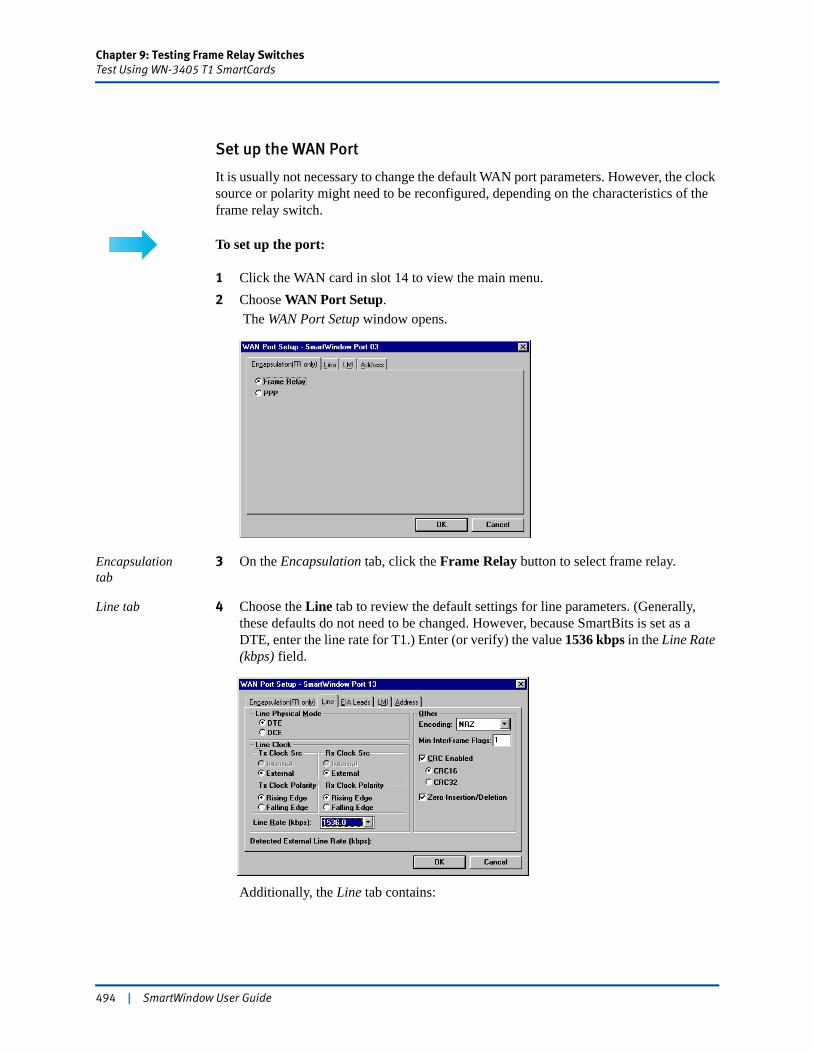
Chapter 9: Testing Frame Relay SwitchesTest Using WN-3405 T1 SmartCards
Set up the WAN Port
It is usually not necessary to change the default WAN port parameters. However, the clock source or polarity might need to be reconfigured, depending on the characteristics of the frame relay switch.
To set up the port:
1 Click the WAN card in slot 14 to view the main menu.2 Choose WAN Port Setup.
The WAN Port Setup window opens.
Encapsulation tab
3 On the Encapsulation tab, click the Frame Relay button to select frame relay.
Line tab 4 Choose the Line tab to review the default settings for line parameters. (Generally, these defaults do not need to be changed. However, because SmartBits is set as a DTE, enter the line rate for T1.) Enter (or verify) the value 1536 kbps in the Line Rate (kbps) field.
Additionally, the Line tab contains:
494 | SmartWindow User Guide
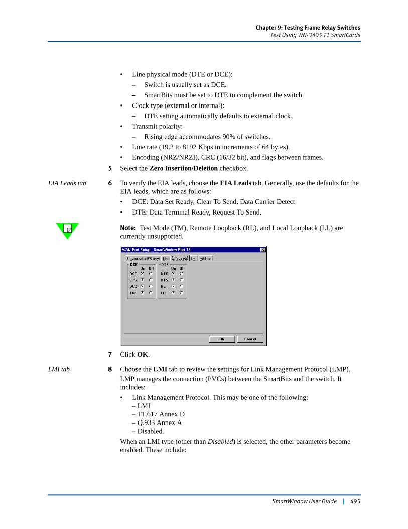
Chapter 9: Testing Frame Relay SwitchesTest Using WN-3405 T1 SmartCards
• Line physical mode (DTE or DCE):– Switch is usually set as DCE.– SmartBits must be set to DTE to complement the switch.
• Clock type (external or internal):– DTE setting automatically defaults to external clock.
• Transmit polarity:– Rising edge accommodates 90% of switches.
• Line rate (19.2 to 8192 Kbps in increments of 64 bytes).• Encoding (NRZ/NRZI), CRC (16/32 bit), and flags between frames.
5 Select the Zero Insertion/Deletion checkbox.
EIA Leads tab 6 To verify the EIA leads, choose the EIA Leads tab. Generally, use the defaults for the EIA leads, which are as follows:• DCE: Data Set Ready, Clear To Send, Data Carrier Detect• DTE: Data Terminal Ready, Request To Send.
Note: Test Mode (TM), Remote Loopback (RL), and Local Loopback (LL) are currently unsupported.
7 Click OK.
LMI tab 8 Choose the LMI tab to review the settings for Link Management Protocol (LMP).LMP manages the connection (PVCs) between the SmartBits and the switch. It includes:• Link Management Protocol. This may be one of the following:
– LMI– T1.617 Annex D– Q.933 Annex A– Disabled.
When an LMI type (other than Disabled) is selected, the other parameters become enabled. These include:
SmartWindow User Guide | 495
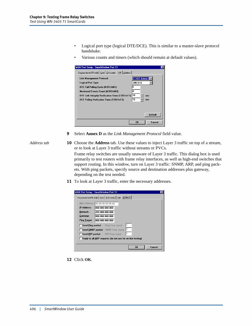
Chapter 9: Testing Frame Relay SwitchesTest Using WN-3405 T1 SmartCards
• Logical port type (logical DTE/DCE). This is similar to a master-slave protocol handshake.
• Various counts and timers (which should remain at default values).
9 Select Annex D as the Link Management Protocol field value.
Address tab 10 Choose the Address tab. Use these values to inject Layer 3 traffic on top of a stream, or to look at Layer 3 traffic without streams or PVCs.Frame relay switches are usually unaware of Layer 3 traffic. This dialog box is used primarily to test routers with frame relay interfaces, as well as high-end switches that support routing. In this window, turn on Layer 3 traffic: SNMP, ARP, and ping pack-ets. With ping packets, specify source and destination addresses plus gateway, depending on the test needed.
11 To look at Layer 3 traffic, enter the necessary addresses.
12 Click OK.
496 | SmartWindow User Guide

Chapter 9: Testing Frame Relay SwitchesTest Using WN-3405 T1 SmartCards
Transmit Setup
Use the Transmit Setup window to configure PVCs and define streams of traffic. Click the WAN card, and choose Transmit Setup.
The Transmit Setup window offers several options:• Edit Stream is used to specify frame length (without FCS), triggers, and errors.• Add PVC is used to add the new PVC and its DLCI number.• Edit PVC is used to edit the PVC for FR parameters.
Typically, first set up the stream with the frame length (without FCS), then edit the PVC and its frame rate to accommodate the frame size. Currently, each PVC supports only one stream.
SmartWindow User Guide | 497
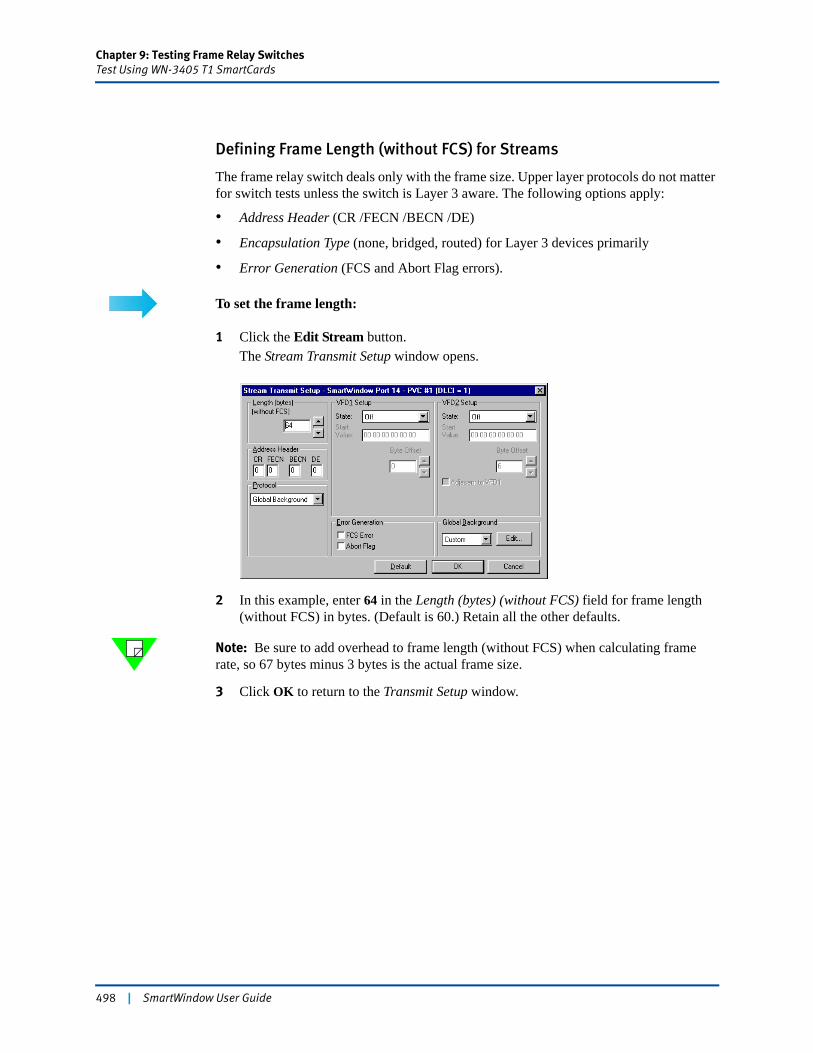
Chapter 9: Testing Frame Relay SwitchesTest Using WN-3405 T1 SmartCards
Defining Frame Length (without FCS) for Streams
The frame relay switch deals only with the frame size. Upper layer protocols do not matter for switch tests unless the switch is Layer 3 aware. The following options apply:
• Address Header (CR /FECN /BECN /DE)
• Encapsulation Type (none, bridged, routed) for Layer 3 devices primarily
• Error Generation (FCS and Abort Flag errors).
To set the frame length:
1 Click the Edit Stream button.The Stream Transmit Setup window opens.
2 In this example, enter 64 in the Length (bytes) (without FCS) field for frame length (without FCS) in bytes. (Default is 60.) Retain all the other defaults.
Note: Be sure to add overhead to frame length (without FCS) when calculating frame rate, so 67 bytes minus 3 bytes is the actual frame size.
3 Click OK to return to the Transmit Setup window.
498 | SmartWindow User Guide
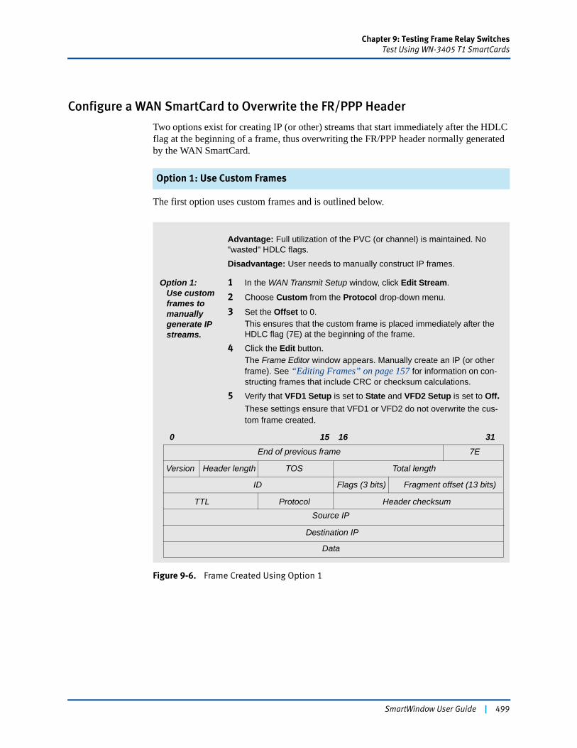
Chapter 9: Testing Frame Relay SwitchesTest Using WN-3405 T1 SmartCards
Configure a WAN SmartCard to Overwrite the FR/PPP Header
Two options exist for creating IP (or other) streams that start immediately after the HDLC flag at the beginning of a frame, thus overwriting the FR/PPP header normally generated by the WAN SmartCard.
Option 1: Use Custom Frames
The first option uses custom frames and is outlined below.
Figure 9-6. Frame Created Using Option 1
Advantage: Full utilization of the PVC (or channel) is maintained. No "wasted" HDLC flags.
Disadvantage: User needs to manually construct IP frames.
Option 1:Use custom frames to manually generate IP streams.
1 In the WAN Transmit Setup window, click Edit Stream.
2 Choose Custom from the Protocol drop-down menu.
3 Set the Offset to 0.This ensures that the custom frame is placed immediately after the HDLC flag (7E) at the beginning of the frame.
4 Click the Edit button.The Frame Editor window appears. Manually create an IP (or other frame). See “Editing Frames” on page 157 for information on con-structing frames that include CRC or checksum calculations.
5 Verify that VFD1 Setup is set to State and VFD2 Setup is set to Off.These settings ensure that VFD1 or VFD2 do not overwrite the cus-tom frame created.
End of previous frame 7E
Header length TOS Total length
ID Flags (3 bits) Fragment offset (13 bits)
Version
TTL Protocol Header checksumSource IP
Destination IP
Data
0 15 16 31
SmartWindow User Guide | 499
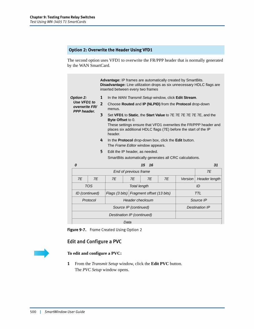
Chapter 9: Testing Frame Relay SwitchesTest Using WN-3405 T1 SmartCards
Option 2: Overwrite the Header Using VFD1
The second option uses VFD1 to overwrite the FR/PPP header that is normally generated by the WAN SmartCard.
Figure 9-7. Frame Created Using Option 2
Edit and Configure a PVC
To edit and configure a PVC:
1 From the Transmit Setup window, click the Edit PVC button.The PVC Setup window opens.
Advantage: IP frames are automatically created by SmartBits.Disadvantage: Line utilization drops as six unnecessary HDLC flags are inserted between every two frames
Option 2:Use VFD1 to overwrite FR/PPP header.
1 In the WAN Transmit Setup window, click Edit Stream.
2 Choose Routed and IP (NLPID) from the Protocol drop-down menus.
3 Set VFD1 to Static, the Start Value to 7E 7E 7E 7E 7E 7E, and the Byte Offset to 0.These settings ensure that VFD1 overwrites the FR/PPP header and places six additional HDLC flags (7E) before the start of the IP header.
4 In the Protocol drop-down box, click the Edit button.The Frame Editor window appears.
5 Edit the IP header, as needed.SmartBits automatically generates all CRC calculations.
End of previous frame 7E
Header length
TOS Total length ID
Flags (3 bits) Fragment offset (13 bits)
Version
TTL
Protocol Header checksum
Source IP (continued)
Destination IP (continued)
Data
0 15 16 31
Source IP
Destination IP
ID (continued)
7E 7E 7E 7E 7E 7E
500 | SmartWindow User Guide
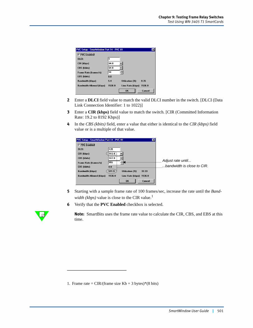
Chapter 9: Testing Frame Relay SwitchesTest Using WN-3405 T1 SmartCards
2 Enter a DLCI field value to match the valid DLCI number in the switch. [DLCI (Data Link Connection Identifier: 1 to 1022)]
3 Enter a CIR (kbps) field value to match the switch. [CIR (Committed Information Rate: 19.2 to 8192 Kbps)]
4 In the CBS (kbits) field, enter a value that either is identical to the CIR (kbps) field value or is a multiple of that value.
5 Starting with a sample frame rate of 100 frames/sec, increase the rate until the Band-width (kbps) value is close to the CIR value.1
6 Verify that the PVC Enabled checkbox is selected.
Note: SmartBits uses the frame rate value to calculate the CIR, CBS, and EBS at this time.
1. Frame rate = CIR/(frame size Kb + 3 bytes)*(8 bits)
Adjust rate until... ...bandwidth is close to CIR.
SmartWindow User Guide | 501
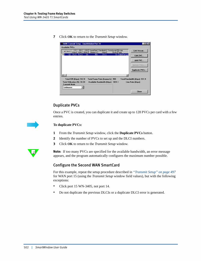
Chapter 9: Testing Frame Relay SwitchesTest Using WN-3405 T1 SmartCards
7 Click OK to return to the Transmit Setup window.
Duplicate PVCs
Once a PVC is created, you can duplicate it and create up to 128 PVCs per card with a few entries.
To duplicate PVCs:
1 From the Transmit Setup window, click the Duplicate PVCs button.2 Identify the number of PVCs to set up and the DLCI numbers.3 Click OK to return to the Transmit Setup window.
Note: If too many PVCs are specified for the available bandwidth, an error message appears, and the program automatically configures the maximum number possible.
Configure the Second WAN SmartCard
For this example, repeat the setup procedure described in “Transmit Setup” on page 497 for WAN port 15 (using the Transmit Setup window field values), but with the following exceptions:
• Click port 15 WN-3405, not port 14.
• Do not duplicate the previous DLCIs or a duplicate DLCI error is generated.
502 | SmartWindow User Guide
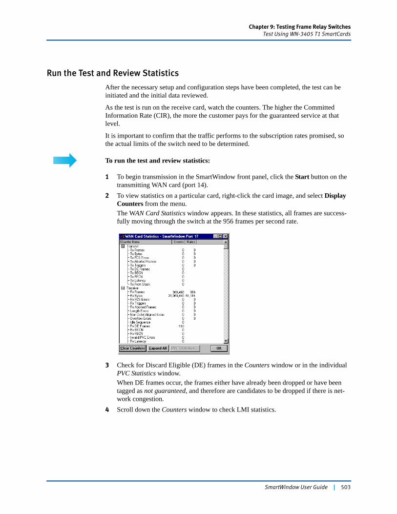
Chapter 9: Testing Frame Relay SwitchesTest Using WN-3405 T1 SmartCards
Run the Test and Review Statistics
After the necessary setup and configuration steps have been completed, the test can be initiated and the initial data reviewed.
As the test is run on the receive card, watch the counters. The higher the Committed Information Rate (CIR), the more the customer pays for the guaranteed service at that level.
It is important to confirm that the traffic performs to the subscription rates promised, so the actual limits of the switch need to be determined.
To run the test and review statistics:
1 To begin transmission in the SmartWindow front panel, click the Start button on the transmitting WAN card (port 14).
2 To view statistics on a particular card, right-click the card image, and select Display Counters from the menu.The WAN Card Statistics window appears. In these statistics, all frames are success-fully moving through the switch at the 956 frames per second rate.
3 Check for Discard Eligible (DE) frames in the Counters window or in the individual PVC Statistics window.When DE frames occur, the frames either have already been dropped or have been tagged as not guaranteed, and therefore are candidates to be dropped if there is net-work congestion.
4 Scroll down the Counters window to check LMI statistics.
SmartWindow User Guide | 503

Chapter 9: Testing Frame Relay SwitchesTest Using WN-3405 T1 SmartCards
Use SmartCounters
Use SmartCounters to save statistics and to see data on a specific port.
To use SmartCounters:
1 Choose Actions > SmartCounters.2 Select File > New to open a new counter window.3 To save the statistical data available at that moment, choose File > Save As from the
SmartCounters menu. The data is saved to an Excel spreadsheet.4 Choose View > Counter Only to see data on a specific port.
Note: Refer to “Set up IGMP for SmartBits 600x/6000x Modules” on page 120 for more complete information.
Determine the Traffic Breakpoint and Frame Rate Impact
The line rate stays the same for all PVCs, but each PVC may be configured for different throughput (56 Kbps, 64 Kbps, etc.). If you subscribe to 512 Kbps, be sure to verify the rate.
Sometimes older frame relay switches contain a T1 circuit/interface, but do not have the physical capability to run at that rate. Therefore, if you are paying for a T1 circuit, but the switch can only transmit at 56 Kbps, the WAN circuit is never saturated so you are not operating in a cost effective manner.
Determine the Traffic Breakpoint
To determine the frame rate at which frames are lost or about to be discarded:
1 In the Transmit Setup window, change the frame rate and/or the frame length (without FCS) to higher values.
504 | SmartWindow User Guide
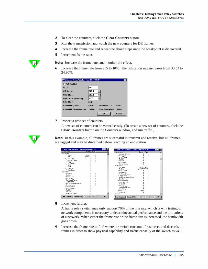
Chapter 9: Testing Frame Relay SwitchesTest Using WN-3405 T1 SmartCards
2 To clear the counters, click the Clear Counters button. 3 Run the transmission and watch the new counters for DE frames.4 Increase the frame rate and repeat the above steps until the breakpoint is discovered.5 Increment frame rates.
Note: Increase the frame rate, and monitor the effect.6 Increase the frame rate from 955 to 1000. The utilization rate increases from 33.33 to
34.90%.
7 Inspect a new set of counters.A new set of counters can be viewed easily. (To create a new set of counters, click the Clear Counters button on the Counters window, and run traffic.)
Note: In this example, all frames are successful in transmit and receive, but DE frames are tagged and may be discarded before reaching an end station.
8 Increment further.A frame relay switch may only support 70% of the line rate, which is why testing of network components is necessary to determine actual performance and the limitations of a network. When either the frame rate or the frame size is increased, the bandwidth goes down.
9 Increase the frame rate to find where the switch runs out of resources and discards frames in order to show physical capability and traffic capacity of the switch as well
SmartWindow User Guide | 505
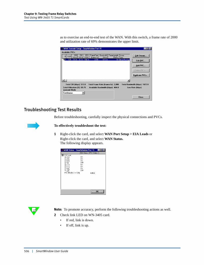
Chapter 9: Testing Frame Relay SwitchesTest Using WN-3405 T1 SmartCards
as to exercise an end-to-end test of the WAN. With this switch, a frame rate of 2000 and utilization rate of 69% demonstrates the upper limit.
Troubleshooting Test Results
Before troubleshooting, carefully inspect the physical connections and PVCs.
To effectively troubleshoot the test:
1 Right-click the card, and select WAN Port Setup > EIA Leads orRight-click the card, and select WAN Status. The following display appears.
Note: To promote accuracy, perform the following troubleshooting actions as well.2 Check link LED on WN-3405 card.
• If red, link is down.• If off, link is up.
506 | SmartWindow User Guide
Chapter 9: Testing Frame Relay SwitchesTest Using WN-3405 T1 SmartCards
3 Check DTR and RTS LEDs on the WAN Status window.• Should be on. (If off, DTR and RTS are not configured on the SmartBits).
4 Check DLCI on the WAN Status window.• Active (desired)• Inactive (Either LMP has not registered with switch, it depends on timer, or there
is a problem.) • Not configured (Check configuration.)
5 Right-click the card and choose WAN Port Setup.• The card should be set to DTE if switch is set as DCE.• Line rate must match switch.• Under LMP, the link management protocol must match the switch settings.
– LMI, annex A, or annex D– Card should show UNI on front; if not, it is disabled.
• EIA leads must be on.6 Check WAN transmit setup.
• The PVC checkbox must be selected.• DLCI number must be valid and match switch port.• Correct CIR.• Frame rate must be set. Zero (the default) does not work.
SmartWindow User Guide | 507
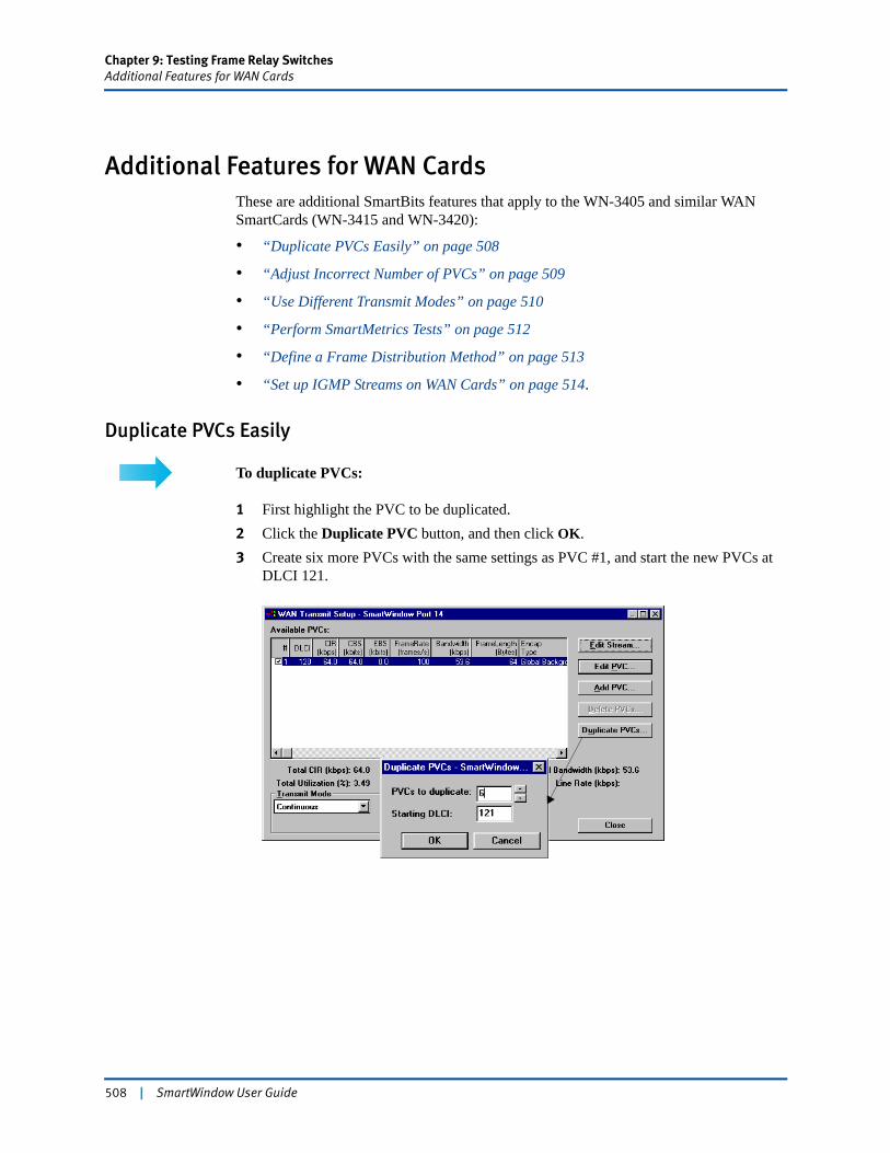
Chapter 9: Testing Frame Relay SwitchesAdditional Features for WAN Cards
Additional Features for WAN CardsThese are additional SmartBits features that apply to the WN-3405 and similar WAN SmartCards (WN-3415 and WN-3420):
• “Duplicate PVCs Easily” on page 508
• “Adjust Incorrect Number of PVCs” on page 509
• “Use Different Transmit Modes” on page 510
• “Perform SmartMetrics Tests” on page 512
• “Define a Frame Distribution Method” on page 513
• “Set up IGMP Streams on WAN Cards” on page 514.
Duplicate PVCs Easily
To duplicate PVCs:
1 First highlight the PVC to be duplicated.2 Click the Duplicate PVC button, and then click OK.3 Create six more PVCs with the same settings as PVC #1, and start the new PVCs at
DLCI 121.
508 | SmartWindow User Guide
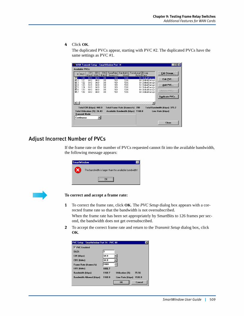
Chapter 9: Testing Frame Relay SwitchesAdditional Features for WAN Cards
4 Click OK.The duplicated PVCs appear, starting with PVC #2. The duplicated PVCs have the same settings as PVC #1.
Adjust Incorrect Number of PVCs
If the frame rate or the number of PVCs requested cannot fit into the available bandwidth, the following message appears:
To correct and accept a frame rate:
1 To correct the frame rate, click OK. The PVC Setup dialog box appears with a cor-rected frame rate so that the bandwidth is not oversubscribed.When the frame rate has been set appropriately by SmartBits to 126 frames per sec-ond, the bandwidth does not get oversubscribed.
2 To accept the correct frame rate and return to the Transmit Setup dialog box, click OK.
SmartWindow User Guide | 509
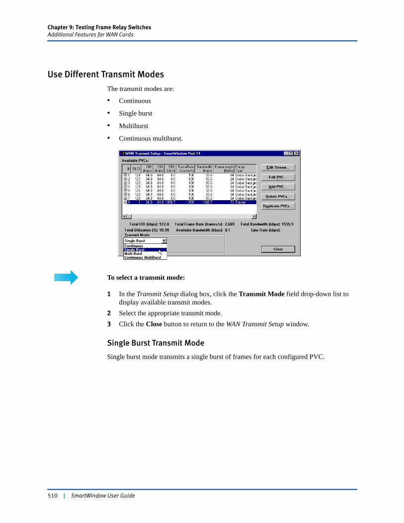
Chapter 9: Testing Frame Relay SwitchesAdditional Features for WAN Cards
Use Different Transmit Modes
The transmit modes are:
• Continuous
• Single burst
• Multiburst
• Continuous multiburst.
To select a transmit mode:
1 In the Transmit Setup dialog box, click the Transmit Mode field drop-down list to display available transmit modes.
2 Select the appropriate transmit mode.3 Click the Close button to return to the WAN Transmit Setup window.
Single Burst Transmit Mode
Single burst mode transmits a single burst of frames for each configured PVC.
510 | SmartWindow User Guide
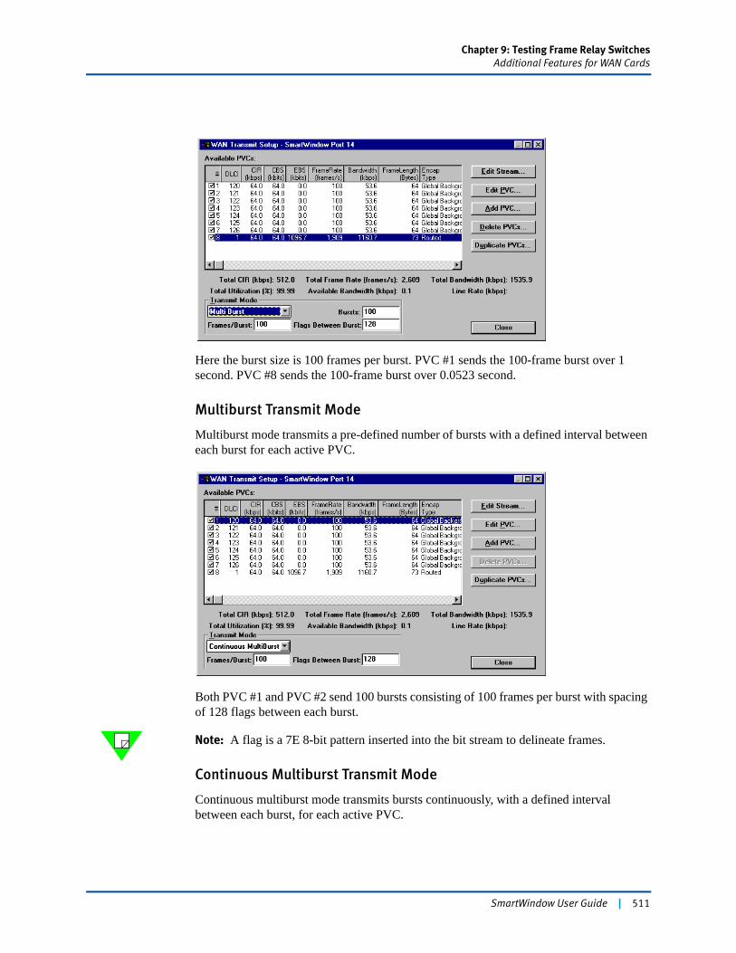
Chapter 9: Testing Frame Relay SwitchesAdditional Features for WAN Cards
Here the burst size is 100 frames per burst. PVC #1 sends the 100-frame burst over 1 second. PVC #8 sends the 100-frame burst over 0.0523 second.
Multiburst Transmit Mode
Multiburst mode transmits a pre-defined number of bursts with a defined interval between each burst for each active PVC.
Both PVC #1 and PVC #2 send 100 bursts consisting of 100 frames per burst with spacing of 128 flags between each burst.
Note: A flag is a 7E 8-bit pattern inserted into the bit stream to delineate frames.
Continuous Multiburst Transmit Mode
Continuous multiburst mode transmits bursts continuously, with a defined interval between each burst, for each active PVC.
SmartWindow User Guide | 511
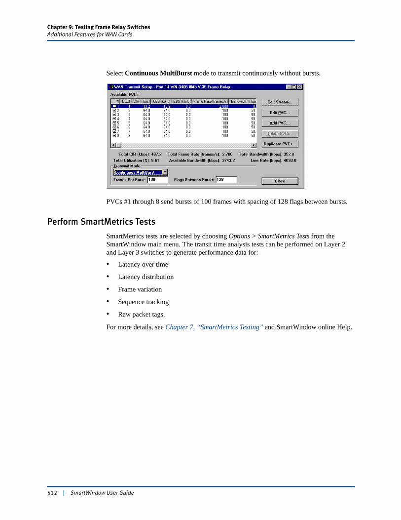
Chapter 9: Testing Frame Relay SwitchesAdditional Features for WAN Cards
Select Continuous MultiBurst mode to transmit continuously without bursts.
PVCs #1 through 8 send bursts of 100 frames with spacing of 128 flags between bursts.
Perform SmartMetrics Tests
SmartMetrics tests are selected by choosing Options > SmartMetrics Tests from the SmartWindow main menu. The transit time analysis tests can be performed on Layer 2 and Layer 3 switches to generate performance data for:
• Latency over time
• Latency distribution
• Frame variation
• Sequence tracking
• Raw packet tags.
For more details, see Chapter 7, “SmartMetrics Testing” and SmartWindow online Help.
512 | SmartWindow User Guide
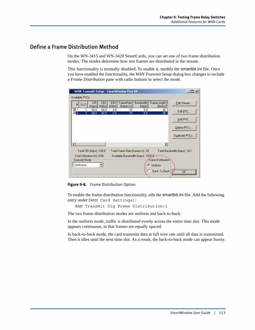
Chapter 9: Testing Frame Relay SwitchesAdditional Features for WAN Cards
Define a Frame Distribution Method
On the WN-3415 and WN-3420 SmartCards, you can set one of two frame distribution modes. The modes determine how test frames are distributed in the stream.
This functionality is normally disabled. To enable it, modify the smartbit.ini file. Once you have enabled the functionality, the WAN Transmit Setup dialog box changes to include a Frame Distribution pane with radio buttons to select the mode.
Figure 9-8. Frame Distribution Option
To enable the frame distribution functionality, edit the smartbit.ini file. Add the following entry under [WAN Card Settings]:
WAN Transmit Dlg Frame Distribution=1
The two frame distribution modes are uniform and back-to-back.
In the uniform mode, traffic is distributed evenly across the entire time slot. This mode appears continuous, in that frames are equally spaced.
In back-to-back mode, the card transmits data at full wire rate until all data is transmitted. Then it idles until the next time slot. As a result, the back-to-back mode can appear bursty.
SmartWindow User Guide | 513
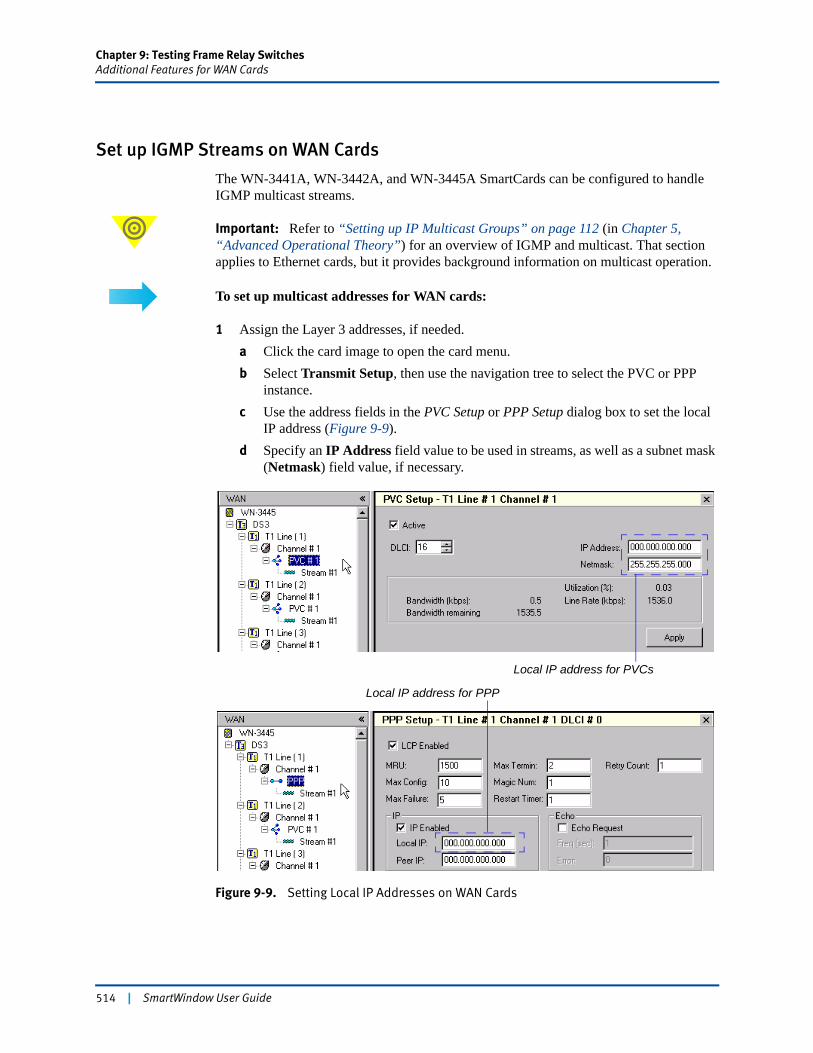
Chapter 9: Testing Frame Relay SwitchesAdditional Features for WAN Cards
Set up IGMP Streams on WAN Cards
The WN-3441A, WN-3442A, and WN-3445A SmartCards can be configured to handle IGMP multicast streams.
Important: Refer to “Setting up IP Multicast Groups” on page 112 (in Chapter 5, “Advanced Operational Theory”) for an overview of IGMP and multicast. That section applies to Ethernet cards, but it provides background information on multicast operation.
To set up multicast addresses for WAN cards:
1 Assign the Layer 3 addresses, if needed.a Click the card image to open the card menu.b Select Transmit Setup, then use the navigation tree to select the PVC or PPP
instance.c Use the address fields in the PVC Setup or PPP Setup dialog box to set the local
IP address (Figure 9-9).d Specify an IP Address field value to be used in streams, as well as a subnet mask
(Netmask) field value, if necessary.
Figure 9-9. Setting Local IP Addresses on WAN Cards
Local IP address for PVCs
Local IP address for PPP
514 | SmartWindow User Guide
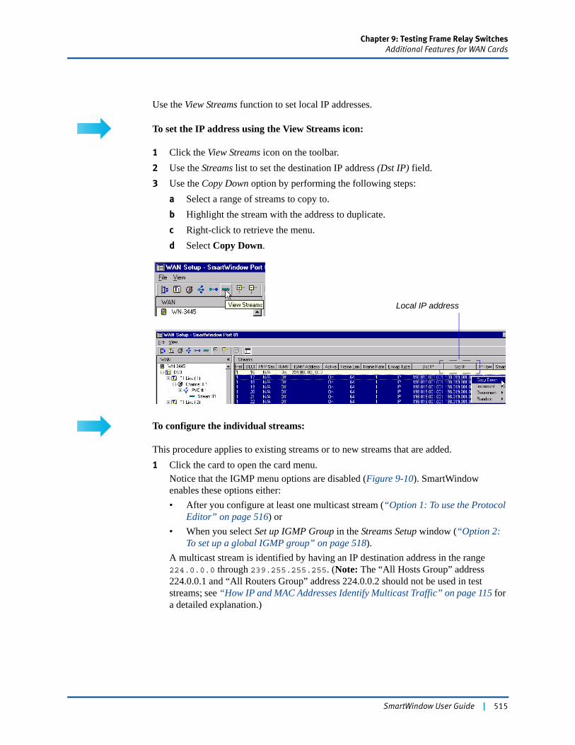
Chapter 9: Testing Frame Relay SwitchesAdditional Features for WAN Cards
Use the View Streams function to set local IP addresses.
To set the IP address using the View Streams icon:
1 Click the View Streams icon on the toolbar.2 Use the Streams list to set the destination IP address (Dst IP) field.3 Use the Copy Down option by performing the following steps:
a Select a range of streams to copy to.b Highlight the stream with the address to duplicate.c Right-click to retrieve the menu.d Select Copy Down.
To configure the individual streams:
This procedure applies to existing streams or to new streams that are added.1 Click the card to open the card menu.
Notice that the IGMP menu options are disabled (Figure 9-10). SmartWindow enables these options either:• After you configure at least one multicast stream (“Option 1: To use the Protocol
Editor” on page 516) or• When you select Set up IGMP Group in the Streams Setup window (“Option 2:
To set up a global IGMP group” on page 518).A multicast stream is identified by having an IP destination address in the range 224.0.0.0 through 239.255.255.255. (Note: The “All Hosts Group” address 224.0.0.1 and “All Routers Group” address 224.0.0.2 should not be used in test streams; see “How IP and MAC Addresses Identify Multicast Traffic” on page 115 for a detailed explanation.)
Local IP address
SmartWindow User Guide | 515
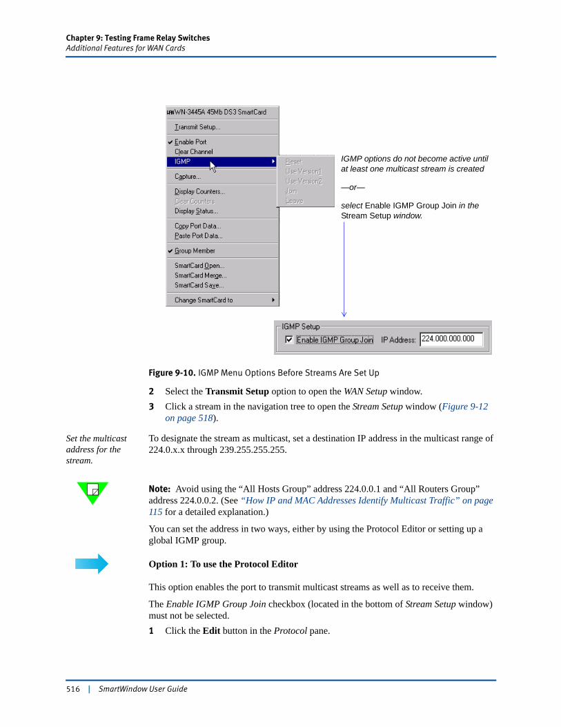
Chapter 9: Testing Frame Relay SwitchesAdditional Features for WAN Cards
Figure 9-10. IGMP Menu Options Before Streams Are Set Up
2 Select the Transmit Setup option to open the WAN Setup window.3 Click a stream in the navigation tree to open the Stream Setup window (Figure 9-12
on page 518).
Set the multicast address for the stream.
To designate the stream as multicast, set a destination IP address in the multicast range of 224.0.x.x through 239.255.255.255.
Note: Avoid using the “All Hosts Group” address 224.0.0.1 and “All Routers Group” address 224.0.0.2. (See “How IP and MAC Addresses Identify Multicast Traffic” on page 115 for a detailed explanation.)
You can set the address in two ways, either by using the Protocol Editor or setting up a global IGMP group.
Option 1: To use the Protocol Editor
This option enables the port to transmit multicast streams as well as to receive them.
The Enable IGMP Group Join checkbox (located in the bottom of Stream Setup window) must not be selected.1 Click the Edit button in the Protocol pane.
IGMP options do not become active until at least one multicast stream is created
—or—
select Enable IGMP Group Join in the Stream Setup window.
516 | SmartWindow User Guide
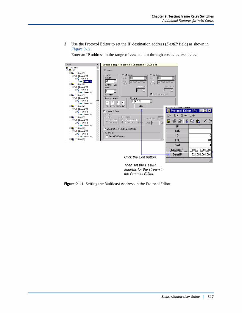
Chapter 9: Testing Frame Relay SwitchesAdditional Features for WAN Cards
2 Use the Protocol Editor to set the IP destination address (DestIP field) as shown in Figure 9-11.Enter an IP address in the range of 224.0.0.0 through 239.255.255.255.
Figure 9-11. Setting the Multicast Address in the Protocol Editor
Click the Edit button.
Then set the DestIP address for the stream in the Protocol Editor.
SmartWindow User Guide | 517
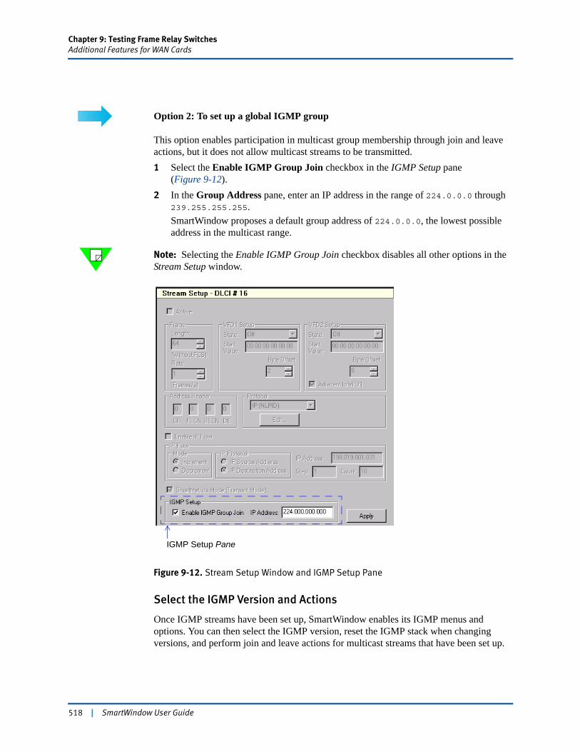
Chapter 9: Testing Frame Relay SwitchesAdditional Features for WAN Cards
Option 2: To set up a global IGMP group
This option enables participation in multicast group membership through join and leave actions, but it does not allow multicast streams to be transmitted.1 Select the Enable IGMP Group Join checkbox in the IGMP Setup pane
(Figure 9-12).2 In the Group Address pane, enter an IP address in the range of 224.0.0.0 through
239.255.255.255.SmartWindow proposes a default group address of 224.0.0.0, the lowest possible address in the multicast range.
Note: Selecting the Enable IGMP Group Join checkbox disables all other options in the Stream Setup window.
Figure 9-12. Stream Setup Window and IGMP Setup Pane
Select the IGMP Version and Actions
Once IGMP streams have been set up, SmartWindow enables its IGMP menus and options. You can then select the IGMP version, reset the IGMP stack when changing versions, and perform join and leave actions for multicast streams that have been set up.
IGMP Setup Pane
518 | SmartWindow User Guide
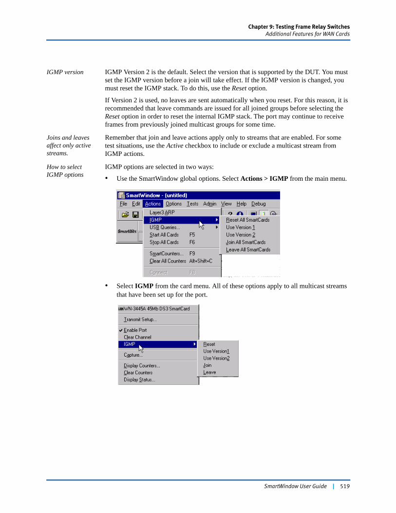
Chapter 9: Testing Frame Relay SwitchesAdditional Features for WAN Cards
IGMP version IGMP Version 2 is the default. Select the version that is supported by the DUT. You must set the IGMP version before a join will take effect. If the IGMP version is changed, you must reset the IGMP stack. To do this, use the Reset option.
If Version 2 is used, no leaves are sent automatically when you reset. For this reason, it is recommended that leave commands are issued for all joined groups before selecting the Reset option in order to reset the internal IGMP stack. The port may continue to receive frames from previously joined multicast groups for some time.
Joins and leaves affect only active streams.
Remember that join and leave actions apply only to streams that are enabled. For some test situations, use the Active checkbox to include or exclude a multicast stream from IGMP actions.
How to select IGMP options
IGMP options are selected in two ways:
• Use the SmartWindow global options. Select Actions > IGMP from the main menu.
• Select IGMP from the card menu. All of these options apply to all multicast streams that have been set up for the port.
SmartWindow User Guide | 519

520 | SmartWindow User Guide
Chapter 10
Testing ATM
The SmartBits chassis, ATM SmartCards, and SmartWindow provide a highly effective test methodology when seeking critical data to evaluate ATM devices.
This chapter presents a detailed set of procedures for testing ATM device performance.
In this chapter...
• Testing ATM . . . . 522
• Establishing PVCs . . . . 525
• PPP over ATM . . . . 532
• Establishing SVCs . . . . 538
• Obtaining Latency Measurements . . . . 553
SmartWindow User Guide | 521
Chapter 10: Testing ATMTesting ATM
Testing ATM
Asynchronous Transfer Mode (ATM) is a connection-based technology. It requires that a specific path be established between two endpoints before data can be transferred between them.
The ATM series of SmartCards can be used to generate and monitor ATM network traffic. Applications include testing:
• ATM-to-LAN internet working devices
• Very high-performance ATM backbones
• LAN-to-ATM edge devices.
Among the significant capabilities of these low cost/high performance ATM cards are:
• Frame-level testing at full-duplex, full-wire rate on edge devices and switches
• Switch testing at full-cell rate
• High-rate signaling testing for edge devices.
SmartWindow uses the concept of streams as a transmission engine. When a stream is created, you define what to transmit, how and where to transmit it, and how fast to transmit it.
The what to transmit is the frame that a stream will use. Each time a stream is created, you must define a frame template (a data pattern) that the card can use to create and transmit test traffic. When the Start button is clicked, the stream transmits that data pattern repeatedly in its assigned turn.
The how and where to transmit depend greatly on stream type and encapsulation. The two stream types are Permanent Virtual Connections (PVC) and Switched Virtual Connections (SVC). In ATM, one physical pipe is used to transmit and receive all data, but the pipe can be divided into channels (as in television transmission). When a data cell is transmitted, its data channel is indicated by two fields in the cell header that is included in each cell. These are the Virtual Path Identifier (VPI) and Virtual Channel Identifier (VCI) fields.
PVCs
For PVCs, specify the VPI/VCI on which the stream is supposed to transmit the frame. The card verifies that the specified VPI/VCI is not already used by another stream on the card. In addition, it verifies that there is enough system memory to send and receive data on the VPI/VCI associated with that stream.
SVCs
For SVCs, the network to which the ATM card is connected selects the VPI/VCI; thus, do not specify a VPI/VCI. However, specify certain signaling parameters that indicate to the network what data to transmit, its destination, how the network should handle it, and how
522 | SmartWindow User Guide
Chapter 10: Testing ATMTesting ATM
fast to send it. The card sends these signaling parameters to the network and waits for the network to assign a VPI/VCI to use in sending the data frames of the stream. If the network switch agrees with the requested signaling parameters, it assigns a VPI/VCI. The card then ensures that enough resources are available for using the assigned VPI/VCI.
This procedure is much the same for both PVCs and SVCs, although the setup for an SVC can be more complex and varied, depending on the encapsulation type. Once the setup process has completed for either a PVC or SVC, the stream is said to be in a connected state. A connection index number is assigned by the card as a reference number for the connection. (The term connection index is nearly interchangeable with the term VPI/VCI. However, the value of the connection index has no relation to the value of the VPI/VCI or to the stream number which is using the VPI/VCI. It is simply a value used to identify a VPI/VCI when retrieving statistics.)
Note: Refer to the “ATM Glossary” on page 524 for definitions of key terms.
Understanding Variations in Cell Rates
ATM cell transmission follows a generic cell rate algorithm, which attempts to regulate output for optimal speed and efficiency. In some test setups, the algorithm can produce an actual cell rate that differs from requested rate. This occurs when you set up multiple streams with multiple stream sizes, with the result that the first stream starts to reduce throughput.
ATM is able to multiplex cells from different virtual connections onto a single physical interface. Any time more than one VC has been configured, it becomes possible that the two VCs may try to send a cell during a given cell time. (This is true of any ATM implementation.) When this happens, the cell of one VC is pushed to a later transmit time. Because of the generic cell rate algorithm, which defines the conformance of cell transmissions, a VC can lose time, but it cannot transmit a subsequent cell earlier than normal to make up for the previously lost time. As a result, the actual rate may be less than the requested rate.
SmartWindow User Guide | 523

Chapter 10: Testing ATMTesting ATM
ATM Glossary
ATM Adaptation Layer 5 (AAL 5) A variable bit rate, delay tolerant, connection-based data transport standard.
Asynchronous Transfer Mode (ATM) A transfer mode that organizes data into cells.
ATM cell A 53-byte cell (5-byte header and 48 bytes for data). Each cell contains a VPI and a VCI in its 5-byte header.
ATM address A 20-byte address, consisting of a 13-byte ATM network prefix (OSI Network Service Access Point–NSAP) and 7-byte host part, of which six bytes, the ESI (End System Identifier), is the host MAC address.
ATM Address Resolution Protocol (ARP) The procedure used to resolve an IP address into a ATM address.
Broadcast/Unknown Server (BUS) Broadcasts inquiries on destination addresses that originate on the ATM network to all LEC clients on the emulated LAN.
Emulated Local Area Network (ELAN) A group of ATM and legacy devices registered with the LES that constitutes a logical network.
Frame A data pattern that a stream transmits.
Interim Local Management Interface (ILMI) Discovers and registers ATM addresses of attached hosts.
LAN Emulation (LANE) Allows an ATM network to function as a LAN backbone or WAN connection. Consists of LANE clients and LANE services.
LAN Emulation Client (LEC) A device such as server, switch, or workstation that performs ATM signaling and control functions while communicating with other devices in an ELAN. Every LEC client has an ATM address and a MAC address.
LAN Emulation Configuration Server (LECS) Provides mapping information about ELANs on the ATM network that a LEC may join.
LAN Emulation Server (LES) Registers the MAC addresses of each LEC on the non-ATM destination LAN and resolves the MAC address to an ATM address.
MAC address A 6-byte IEEE identifier for hardware devices, sometimes referred to as hardware address.
Permanent Virtual Circuit (PVC) A dedicated channel between endpoints through an ATM network used for long-term data transfer.
Stream An engine which defines where and how to transmit a frame over and over repeatedly.
Switched Virtual Circuit (SVC) A channel established on demand by ATM signaling that lasts only the duration of the transfer.
Virtual Channel Connection (VCC) A unidirectional communications path between two nodes based on label rather than fixed physical path that extends between two points in the ATM layer.
Virtual Channel Identifier (VCI) / Virtual Path Identifier (VPI) A connection in the form of a channel which has been successfully initialized and on which data is ready to be transmitted and received. Provides mapping information for routing cells from a source to destination.
524 | SmartWindow User Guide
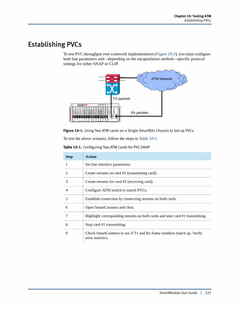
Chapter 10: Testing ATMEstablishing PVCs
Establishing PVCsTo test PVC throughput over a network implementation (Figure 10-1), you must configure both line parameters and—depending on the encapsulation method—specific protocol settings for either SNAP or CLIP.
Figure 10-1. Using Two ATM cards on a Single SmartBits Chassis to Set up PVCs
To test the above scenario, follow the steps in Table 10-1.
Table 10-1. Configuring Two ATM Cards for PVC-SNAP
Step Action
1 Set line interface parameters.
2 Create streams on card #1 (transmitting card).
3 Create streams for card #2 (receiving card).
4 Configure ATM switch to match PVCs.
5 Establish connection by connecting streams on both cards.
6 Open SmartCounters and clear.
7 Highlight corresponding streams on both cards and start card #1 transmitting.
8 Stop card #1 transmitting.
9 Check SmartCounters to see if Tx and Rx frame numbers match up. Verify error statistics.
ATM Network
TX packets
Rx packets
SmartWindow User Guide | 525
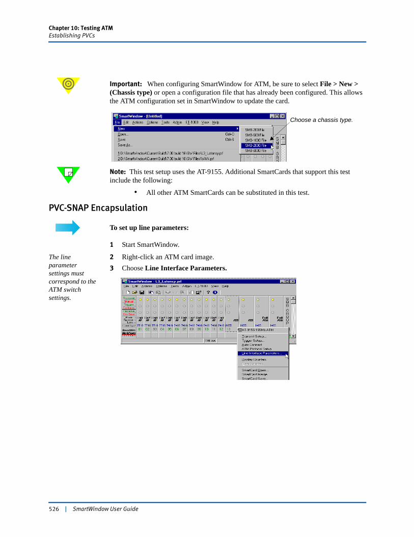
Chapter 10: Testing ATMEstablishing PVCs
Important: When configuring SmartWindow for ATM, be sure to select File > New >(Chassis type) or open a configuration file that has already been configured. This allows the ATM configuration set in SmartWindow to update the card.
Note: This test setup uses the AT-9155. Additional SmartCards that support this test include the following:
• All other ATM SmartCards can be substituted in this test.
PVC-SNAP Encapsulation
To set up line parameters:
1 Start SmartWindow.
The line parameter settings must correspond to the ATM switch settings.
2 Right-click an ATM card image.3 Choose Line Interface Parameters.
Choose a chassis type.
526 | SmartWindow User Guide
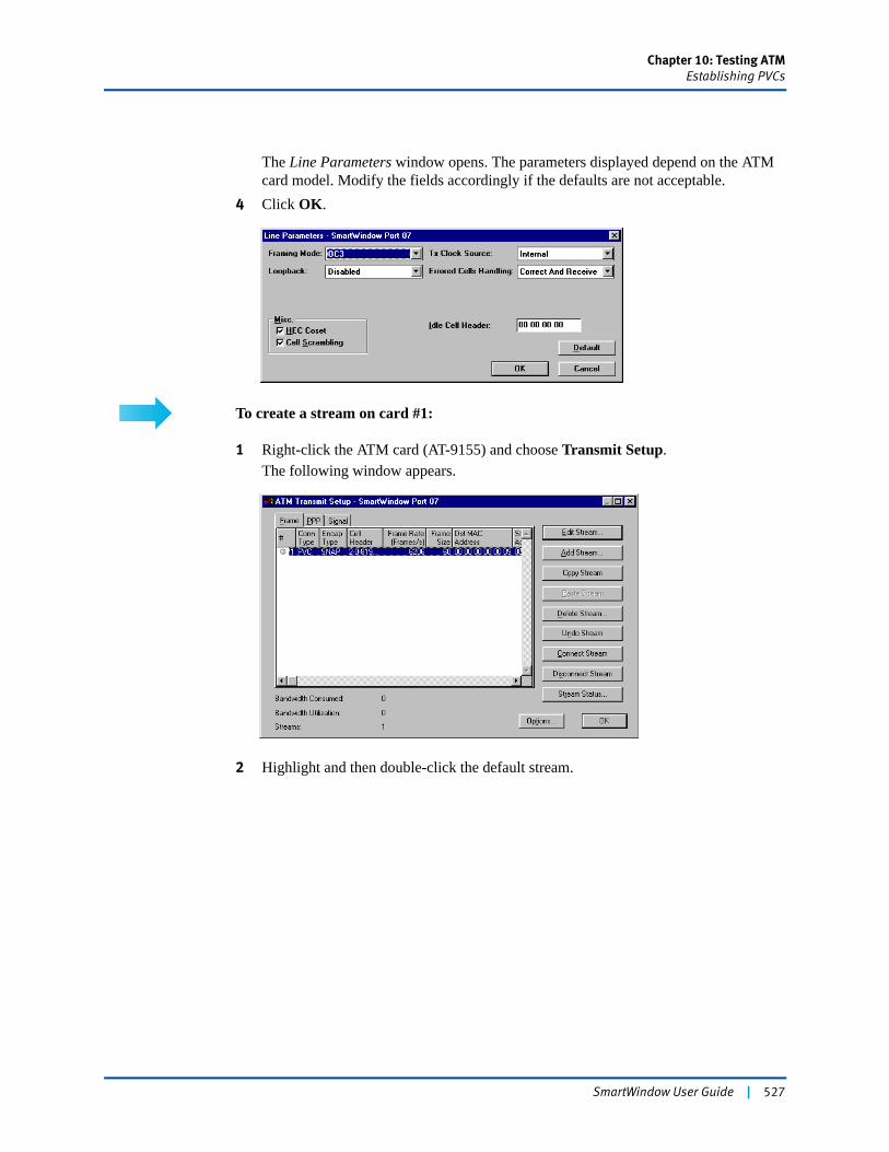
Chapter 10: Testing ATMEstablishing PVCs
The Line Parameters window opens. The parameters displayed depend on the ATM card model. Modify the fields accordingly if the defaults are not acceptable.
4 Click OK.
To create a stream on card #1:
1 Right-click the ATM card (AT-9155) and choose Transmit Setup.The following window appears.
2 Highlight and then double-click the default stream.
SmartWindow User Guide | 527
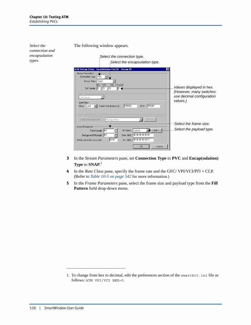
Chapter 10: Testing ATMEstablishing PVCs
Select the connection and encapsulation types.
The following window appears.
3 In the Stream Parameters pane, set Connection Type to PVC and Encap(sulation) Type to SNAP.1
4 In the Rate Class pane, specify the frame rate and the GFC/ VPI/VCI/PTI + CLP. (Refer to Table 10-5 on page 542 for more information.)
5 In the Frame Parameters pane, select the frame size and payload type from the Fill Pattern field drop-down menu.
1. To change from hex to decimal, edit the preferences section of the smartbit.ini file as follows: ATM VPI/VCI HEX=0.
Select the encapsulation type.Select the connection type.
Values displayed in hex. (However, many switches use decimal configuration values.)
Select the frame size.Select the payload type.
528 | SmartWindow User Guide
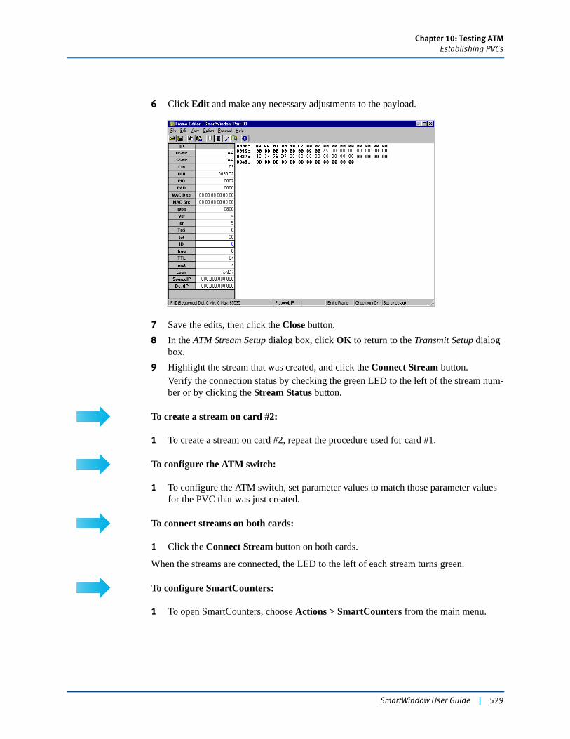
Chapter 10: Testing ATMEstablishing PVCs
6 Click Edit and make any necessary adjustments to the payload.
7 Save the edits, then click the Close button.8 In the ATM Stream Setup dialog box, click OK to return to the Transmit Setup dialog
box.9 Highlight the stream that was created, and click the Connect Stream button.
Verify the connection status by checking the green LED to the left of the stream num-ber or by clicking the Stream Status button.
To create a stream on card #2:
1 To create a stream on card #2, repeat the procedure used for card #1.
To configure the ATM switch:
1 To configure the ATM switch, set parameter values to match those parameter values for the PVC that was just created.
To connect streams on both cards:
1 Click the Connect Stream button on both cards.
When the streams are connected, the LED to the left of each stream turns green.
To configure SmartCounters:
1 To open SmartCounters, choose Actions > SmartCounters from the main menu.
SmartWindow User Guide | 529
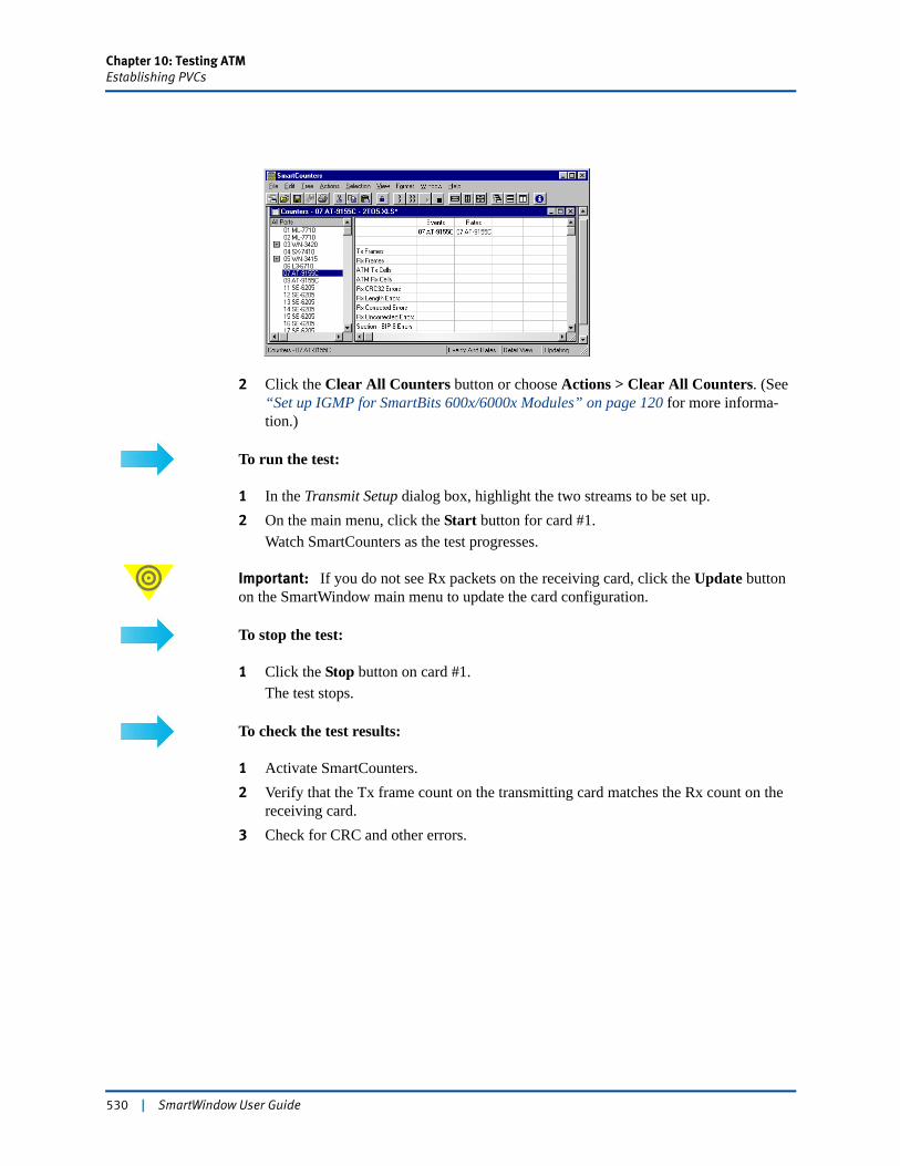
Chapter 10: Testing ATMEstablishing PVCs
2 Click the Clear All Counters button or choose Actions > Clear All Counters. (See “Set up IGMP for SmartBits 600x/6000x Modules” on page 120 for more informa-tion.)
To run the test:
1 In the Transmit Setup dialog box, highlight the two streams to be set up.2 On the main menu, click the Start button for card #1.
Watch SmartCounters as the test progresses.
Important: If you do not see Rx packets on the receiving card, click the Update button on the SmartWindow main menu to update the card configuration.
To stop the test:
1 Click the Stop button on card #1.The test stops.
To check the test results:
1 Activate SmartCounters.2 Verify that the Tx frame count on the transmitting card matches the Rx count on the
receiving card. 3 Check for CRC and other errors.
530 | SmartWindow User Guide
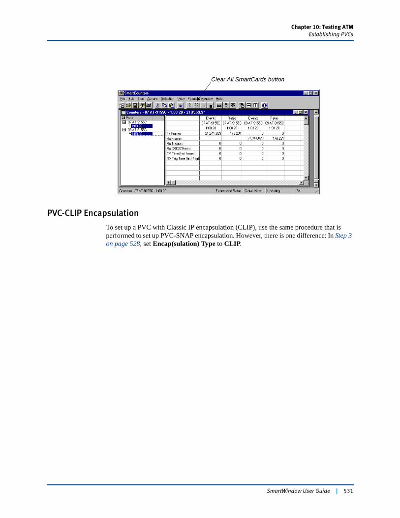
Chapter 10: Testing ATMEstablishing PVCs
PVC-CLIP Encapsulation
To set up a PVC with Classic IP encapsulation (CLIP), use the same procedure that is performed to set up PVC-SNAP encapsulation. However, there is one difference: In Step 3 on page 528, set Encap(sulation) Type to CLIP.
Clear All SmartCards button
SmartWindow User Guide | 531
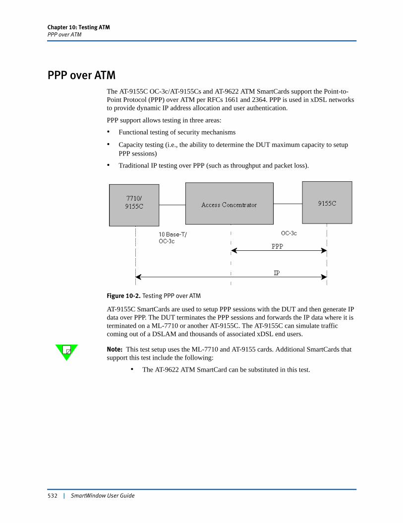
Chapter 10: Testing ATMPPP over ATM
PPP over ATMThe AT-9155C OC-3c/AT-9155Cs and AT-9622 ATM SmartCards support the Point-to-Point Protocol (PPP) over ATM per RFCs 1661 and 2364. PPP is used in xDSL networks to provide dynamic IP address allocation and user authentication.
PPP support allows testing in three areas:
• Functional testing of security mechanisms
• Capacity testing (i.e., the ability to determine the DUT maximum capacity to setup PPP sessions)
• Traditional IP testing over PPP (such as throughput and packet loss).
Figure 10-2. Testing PPP over ATM
AT-9155C SmartCards are used to setup PPP sessions with the DUT and then generate IP data over PPP. The DUT terminates the PPP sessions and forwards the IP data where it is terminated on a ML-7710 or another AT-9155C. The AT-9155C can simulate traffic coming out of a DSLAM and thousands of associated xDSL end users.
Note: This test setup uses the ML-7710 and AT-9155 cards. Additional SmartCards that support this test include the following:
• The AT-9622 ATM SmartCard can be substituted in this test.
532 | SmartWindow User Guide
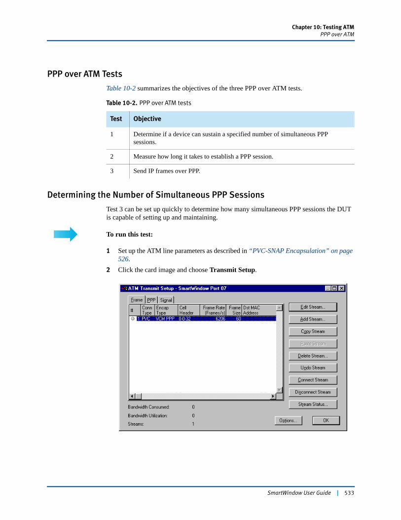
Chapter 10: Testing ATMPPP over ATM
PPP over ATM Tests
Table 10-2 summarizes the objectives of the three PPP over ATM tests.
Determining the Number of Simultaneous PPP Sessions
Test 3 can be set up quickly to determine how many simultaneous PPP sessions the DUT is capable of setting up and maintaining.
To run this test:
1 Set up the ATM line parameters as described in “PVC-SNAP Encapsulation” on page 526.
2 Click the card image and choose Transmit Setup.
Table 10-2. PPP over ATM tests
Test Objective
1 Determine if a device can sustain a specified number of simultaneous PPP sessions.
2 Measure how long it takes to establish a PPP session.
3 Send IP frames over PPP.
SmartWindow User Guide | 533
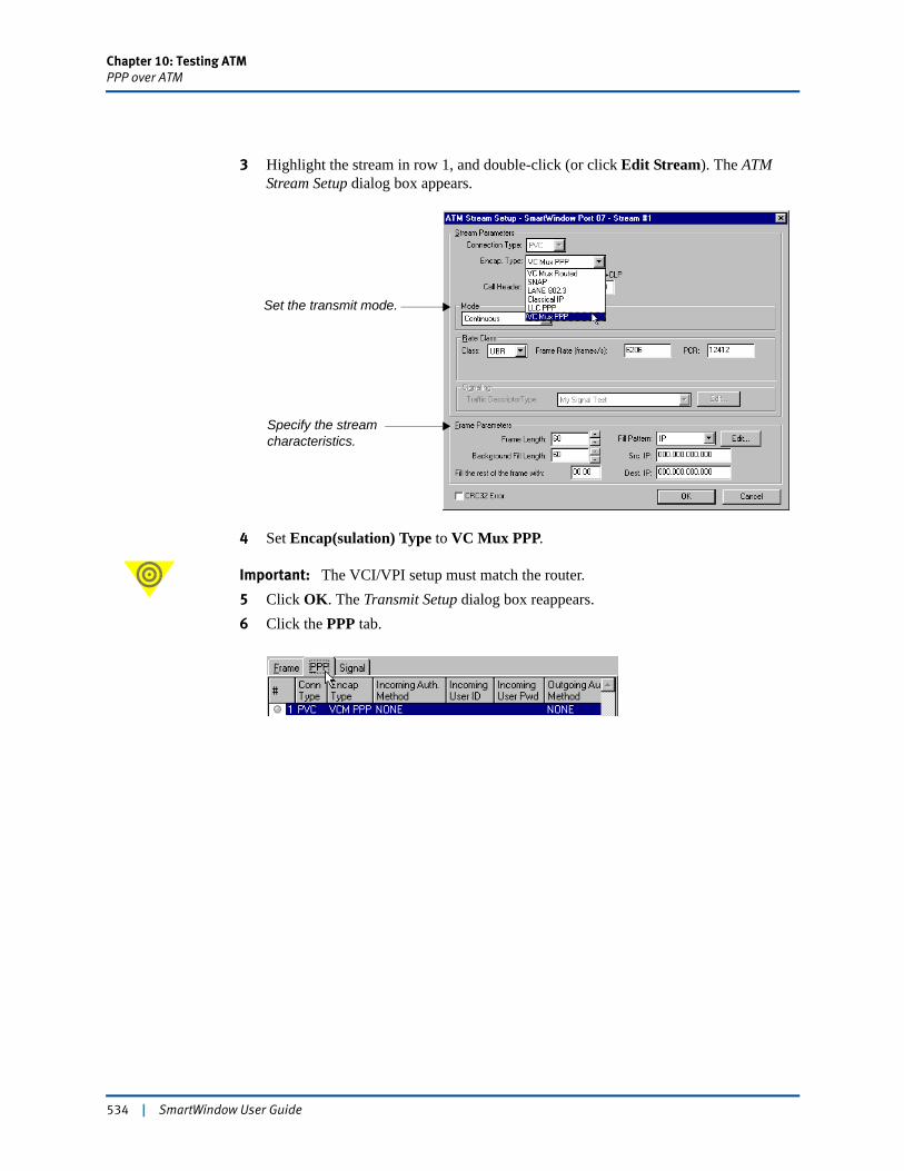
Chapter 10: Testing ATMPPP over ATM
3 Highlight the stream in row 1, and double-click (or click Edit Stream). The ATM Stream Setup dialog box appears.
4 Set Encap(sulation) Type to VC Mux PPP.
Important: The VCI/VPI setup must match the router.5 Click OK. The Transmit Setup dialog box reappears.6 Click the PPP tab.
Set the transmit mode.
Specify the stream characteristics.
534 | SmartWindow User Guide
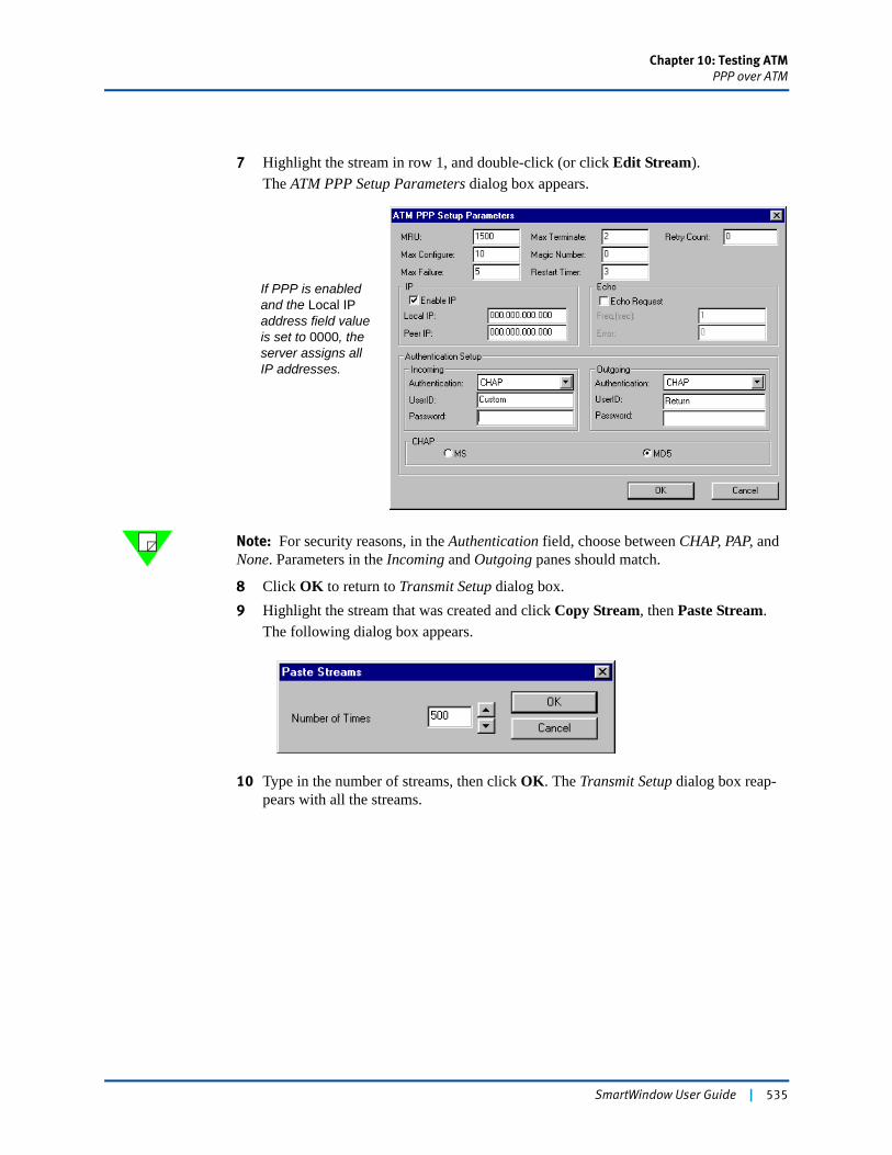
Chapter 10: Testing ATMPPP over ATM
7 Highlight the stream in row 1, and double-click (or click Edit Stream).The ATM PPP Setup Parameters dialog box appears.
Note: For security reasons, in the Authentication field, choose between CHAP, PAP, and None. Parameters in the Incoming and Outgoing panes should match.
8 Click OK to return to Transmit Setup dialog box.9 Highlight the stream that was created and click Copy Stream, then Paste Stream.
The following dialog box appears.
10 Type in the number of streams, then click OK. The Transmit Setup dialog box reap-pears with all the streams.
If PPP is enabled and the Local IP address field value is set to 0000, the server assigns all IP addresses.
SmartWindow User Guide | 535
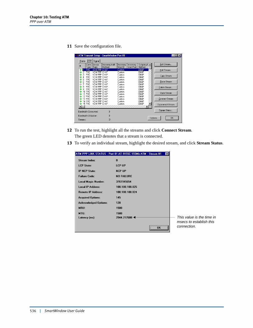
Chapter 10: Testing ATMPPP over ATM
11 Save the configuration file.
12 To run the test, highlight all the streams and click Connect Stream.The green LED denotes that a stream is connected.
13 To verify an individual stream, highlight the desired stream, and click Stream Status.
This value is the time in msecs to establish this connection.
536 | SmartWindow User Guide
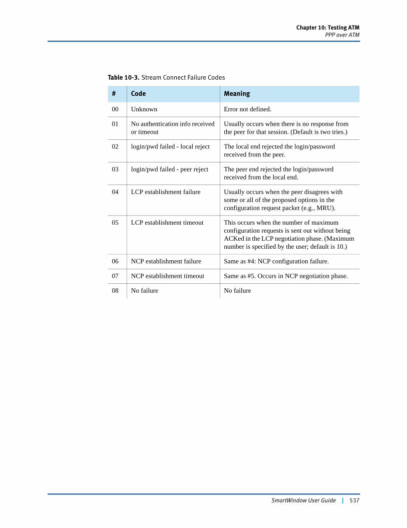
Chapter 10: Testing ATMPPP over ATM
Table 10-3. Stream Connect Failure Codes
# Code Meaning
00 Unknown Error not defined.
01 No authentication info received or timeout
Usually occurs when there is no response from the peer for that session. (Default is two tries.)
02 login/pwd failed - local reject The local end rejected the login/password received from the peer.
03 login/pwd failed - peer reject The peer end rejected the login/password received from the local end.
04 LCP establishment failure Usually occurs when the peer disagrees with some or all of the proposed options in the configuration request packet (e.g., MRU).
05 LCP establishment timeout This occurs when the number of maximum configuration requests is sent out without being ACKed in the LCP negotiation phase. (Maximum number is specified by the user; default is 10.)
06 NCP establishment failure Same as #4: NCP configuration failure.
07 NCP establishment timeout Same as #5. Occurs in NCP negotiation phase.
08 No failure No failure
SmartWindow User Guide | 537
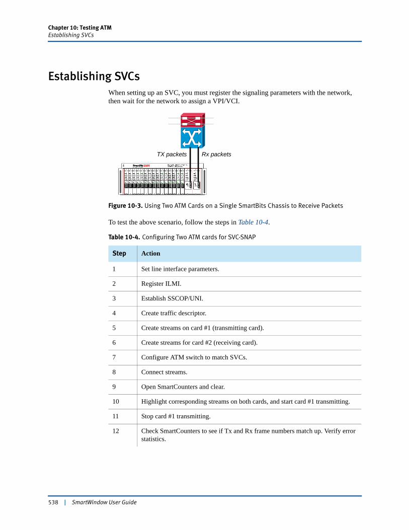
Chapter 10: Testing ATMEstablishing SVCs
Establishing SVCsWhen setting up an SVC, you must register the signaling parameters with the network, then wait for the network to assign a VPI/VCI.
Figure 10-3. Using Two ATM Cards on a Single SmartBits Chassis to Receive Packets
To test the above scenario, follow the steps in Table 10-4.
Table 10-4. Configuring Two ATM cards for SVC-SNAP
Step Action
1 Set line interface parameters.
2 Register ILMI.
3 Establish SSCOP/UNI.
4 Create traffic descriptor.
5 Create streams on card #1 (transmitting card).
6 Create streams for card #2 (receiving card).
7 Configure ATM switch to match SVCs.
8 Connect streams.
9 Open SmartCounters and clear.
10 Highlight corresponding streams on both cards, and start card #1 transmitting.
11 Stop card #1 transmitting.
12 Check SmartCounters to see if Tx and Rx frame numbers match up. Verify error statistics.
TX packets Rx packets
538 | SmartWindow User Guide
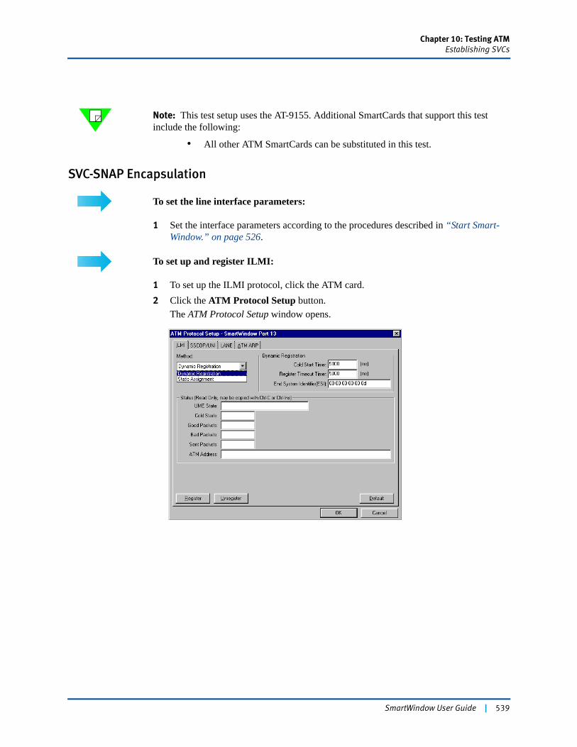
Chapter 10: Testing ATMEstablishing SVCs
Note: This test setup uses the AT-9155. Additional SmartCards that support this test include the following:
• All other ATM SmartCards can be substituted in this test.
SVC-SNAP Encapsulation
To set the line interface parameters:
1 Set the interface parameters according to the procedures described in “Start Smart-Window.” on page 526.
To set up and register ILMI:
1 To set up the ILMI protocol, click the ATM card. 2 Click the ATM Protocol Setup button.
The ATM Protocol Setup window opens.
SmartWindow User Guide | 539
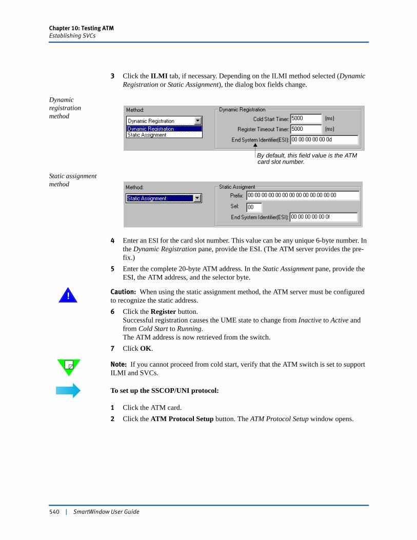
Chapter 10: Testing ATMEstablishing SVCs
3 Click the ILMI tab, if necessary. Depending on the ILMI method selected (Dynamic Registration or Static Assignment), the dialog box fields change.
Dynamic registration method
Static assignment method
4 Enter an ESI for the card slot number. This value can be any unique 6-byte number. In the Dynamic Registration pane, provide the ESI. (The ATM server provides the pre-fix.)
5 Enter the complete 20-byte ATM address. In the Static Assignment pane, provide the ESI, the ATM address, and the selector byte.
! Caution: When using the static assignment method, the ATM server must be configured to recognize the static address.6 Click the Register button.
Successful registration causes the UME state to change from Inactive to Active and from Cold Start to Running.The ATM address is now retrieved from the switch.
7 Click OK.
Note: If you cannot proceed from cold start, verify that the ATM switch is set to support ILMI and SVCs.
To set up the SSCOP/UNI protocol:
1 Click the ATM card. 2 Click the ATM Protocol Setup button. The ATM Protocol Setup window opens.
card slot number.By default, this field value is the ATM
540 | SmartWindow User Guide
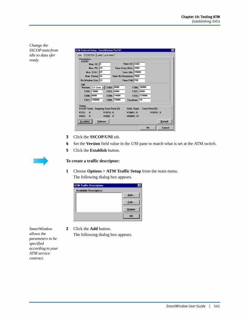
Chapter 10: Testing ATMEstablishing SVCs
Change the SSCOP state from idle to data xfer ready.
3 Click the SSCOP/UNI tab.
4 Set the Version field value in the UNI pane to match what is set at the ATM switch.5 Click the Establish button.
To create a traffic descriptor:
1 Choose Options > ATM Traffic Setup from the main menu.The following dialog box appears.
SmartWindow allows the parameters to be specified according to your ATM service contract.
2 Click the Add button.The following dialog box appears.
SmartWindow User Guide | 541
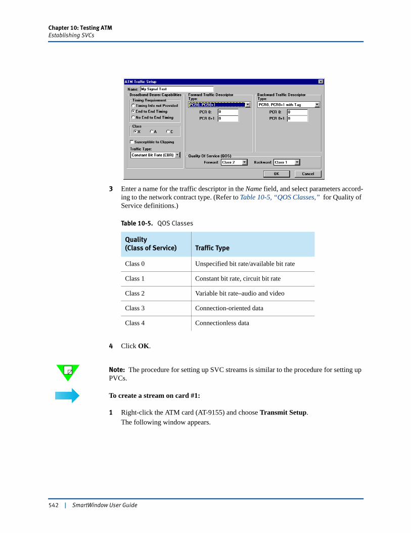
Chapter 10: Testing ATMEstablishing SVCs
3 Enter a name for the traffic descriptor in the Name field, and select parameters accord-ing to the network contract type. (Refer to Table 10-5, “QOS Classes,” for Quality of Service definitions.)
4 Click OK.
Note: The procedure for setting up SVC streams is similar to the procedure for setting up PVCs.
To create a stream on card #1:
1 Right-click the ATM card (AT-9155) and choose Transmit Setup.The following window appears.
Table 10-5. QOS Classes
Quality(Class of Service) Traffic Type
Class 0 Unspecified bit rate/available bit rate
Class 1 Constant bit rate, circuit bit rate
Class 2 Variable bit rate–audio and video
Class 3 Connection-oriented data
Class 4 Connectionless data
542 | SmartWindow User Guide
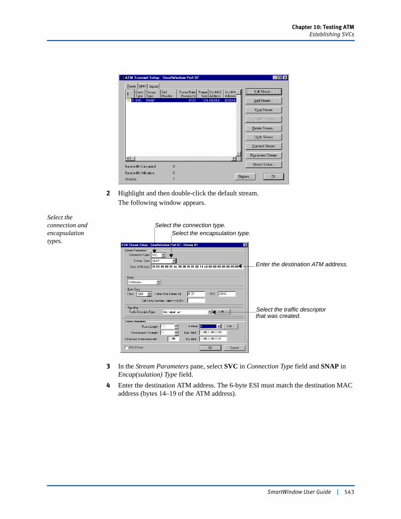
Chapter 10: Testing ATMEstablishing SVCs
2 Highlight and then double-click the default stream.The following window appears.
Select the connection and encapsulation types.
3 In the Stream Parameters pane, select SVC in Connection Type field and SNAP in Encap(sulation) Type field.
4 Enter the destination ATM address. The 6-byte ESI must match the destination MAC address (bytes 14–19 of the ATM address).
Select the encapsulation type.Select the connection type.
Select the traffic descriptor that was created.
Enter the destination ATM address.
SmartWindow User Guide | 543
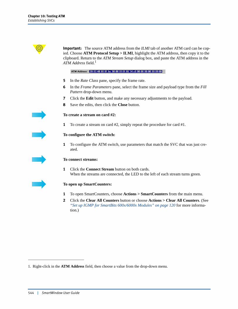
Chapter 10: Testing ATMEstablishing SVCs
Important: The source ATM address from the ILMI tab of another ATM card can be cop-ied. Choose ATM Protocol Setup > ILMI, highlight the ATM address, then copy it to the clipboard. Return to the ATM Stream Setup dialog box, and paste the ATM address in the ATM Address field.1
5 In the Rate Class pane, specify the frame rate.6 In the Frame Parameters pane, select the frame size and payload type from the Fill
Pattern drop-down menu.7 Click the Edit button, and make any necessary adjustments to the payload.8 Save the edits, then click the Close button.
To create a stream on card #2:
1 To create a stream on card #2, simply repeat the procedure for card #1.
To configure the ATM switch:
1 To configure the ATM switch, use parameters that match the SVC that was just cre-ated.
To connect streams:
1 Click the Connect Stream button on both cards. When the streams are connected, the LED to the left of each stream turns green.
To open up SmartCounters:
1 To open SmartCounters, choose Actions > SmartCounters from the main menu.2 Click the Clear All Counters button or choose Actions > Clear All Counters. (See
“Set up IGMP for SmartBits 600x/6000x Modules” on page 120 for more informa-tion.)
1. Right-click in the ATM Address field, then choose a value from the drop-down menu.
544 | SmartWindow User Guide
Chapter 10: Testing ATMEstablishing SVCs
To start the test:
Highlight the streams on cards #1 and #2, and start card #1 transmitting.
1 In the Transmit Setup dialog box, highlight the two streams to be set up.2 On the main menu, click the Start button for card #1.
Watch the SmartCounters as the test progresses.
Important: If there are not any Rx packets on the receiving card, click the Update button on the SmartWindow main menu to update the card with your configuration.
To stop the test:
1 Click the Stop button.The test stops.
To use the SmartCounters:
1 Verify that the Tx frame count on the transmitting card matches the Rx count on the receiving card.
2 Check the test results for CRC and other errors.
SmartWindow User Guide | 545

Chapter 10: Testing ATMEstablishing SVCs
SVC-CLIP Encapsulation
The steps to set up SVC-CLIP are similar to the steps used to set up SVC-SNAP, with the following differences.
To set up SVC-CLIP:
1 Set the interface parameters according to the procedures described in “Start Smart-Window.” on page 526.
2 Register ILMI according to the procedures described in “To set up the ILMI protocol, click the ATM card.” on page 539.
3 Establish SSCOP/UNI according to the procedures described in “Click the ATM card.” on page 540.
4 To establish a CLIP server connection, right-click the ATM ARP tab.The following dialog box appears.
5 Enter the ATM address of the CLIP server in the ARP Server ATM Address field.6 Enter the IP address of the ATM card in the ARP Client IP Address field.7 Create a traffic descriptor according to the procedures in “Choose Options > ATM
Traffic Setup from the main menu.” on page 541.8 Create streams as described in “Right-click the ATM card (AT-9155) and choose
Transmit Setup.” on page 527 and following text.9 Complete the rest of the procedures as outlined in “Configuring Two ATM cards for
SVC-SNAP” on page 538.
546 | SmartWindow User Guide
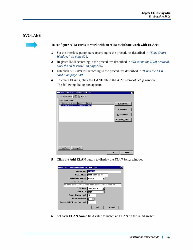
Chapter 10: Testing ATMEstablishing SVCs
SVC-LANE
To configure ATM cards to work with an ATM switch/network with ELANs:
1 Set the interface parameters according to the procedures described in “Start Smart-Window.” on page 526.
2 Register ILMI according to the procedures described in “To set up the ILMI protocol, click the ATM card.” on page 539.
3 Establish SSCOP/UNI according to the procedures described in “Click the ATM card.” on page 540.
4 To create ELANs, click the LANE tab in the ATM Protocol Setup window.The following dialog box appears.
5 Click the Add ELAN button to display the ELAN Setup window.
6 Set each ELAN Name field value to match an ELAN on the ATM switch.
SmartWindow User Guide | 547
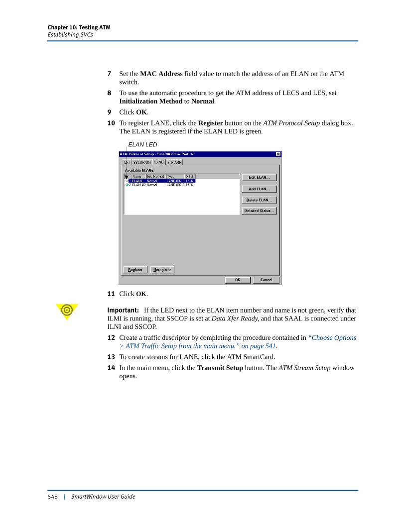
Chapter 10: Testing ATMEstablishing SVCs
7 Set the MAC Address field value to match the address of an ELAN on the ATM switch.
8 To use the automatic procedure to get the ATM address of LECS and LES, setInitialization Method to Normal.
9 Click OK. 10 To register LANE, click the Register button on the ATM Protocol Setup dialog box.
The ELAN is registered if the ELAN LED is green.
11 Click OK.
Important: If the LED next to the ELAN item number and name is not green, verify that ILMI is running, that SSCOP is set at Data Xfer Ready, and that SAAL is connected under ILNI and SSCOP.12 Create a traffic descriptor by completing the procedure contained in “Choose Options
> ATM Traffic Setup from the main menu.” on page 541.13 To create streams for LANE, click the ATM SmartCard.14 In the main menu, click the Transmit Setup button. The ATM Stream Setup window
opens.
ELAN LED
548 | SmartWindow User Guide
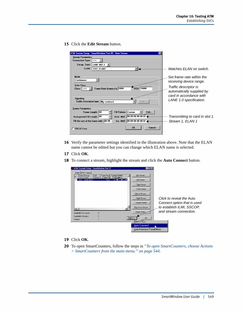
Chapter 10: Testing ATMEstablishing SVCs
15 Click the Edit Stream button.
16 Verify the parameter settings identified in the illustration above. Note that the ELAN name cannot be edited but you can change which ELAN name is selected.
17 Click OK.18 To connect a stream, highlight the stream and click the Auto Connect button.
19 Click OK.20 To open SmartCounters, follow the steps in “To open SmartCounters, choose Actions
> SmartCounters from the main menu.” on page 544.
Matches ELAN on switch.
Set frame rate within the receiving device range.
Transmitting to card in slot 1.Stream 1, ELAN 1
Traffic descriptor is automatically supplied by card in accordance with LANE 1.0 specification.
Click to reveal the Auto Connect option that is used to establish ILMI, SSCOP, and stream connection.
SmartWindow User Guide | 549
Chapter 10: Testing ATMEstablishing SVCs
21 If an error occurs during testing, the following dialog box is displayed.
22 Verify or correct the following conditions:• Is ILMI running?• Is SSCOP set at Data Xfer Ready?• Is SAAL connected?• Is ELAN registered?• Has the switch learned the MAC addresses of the targets?
23 Briefly transmit from the source cards. Then stop the transmission, and try again.
550 | SmartWindow User Guide
Chapter 10: Testing ATMEstablishing SVCs
Incoming SVCs
Important: For this release, incoming SVCs are supported in SmartLibrary, but not in SmartWindow.
Running a New Test
! Caution: When switching between different ATM SVC tests, keep in mind that selecting File > New to set up a new configuration file does not release the previous connection made in ATM Protocol Setup dialog box tabs.
To release an ILMI connection:
1 Right-click the ATM card, and choose ATM Protocol Setup > ILMI.2 Click the Unregister button.
The line is released.
To release an SSCOP/UNI connection:
1 Right-click the ATM card, and choose ATM Protocol Setup > SSCOP/UNI.2 Click the Unregister button.
The line is released.
To release a LANE connection:
1 Right-click the ATM card, and choose ATM Protocol Setup > LANE.2 Click the Unregister button.
The line is released.
To release an ATM ARP connection:
1 Right-click the ATM card, and choose ATM Protocol Setup > ATM ARP.2 Click the Unregister button.
The line is released.
SmartWindow User Guide | 551
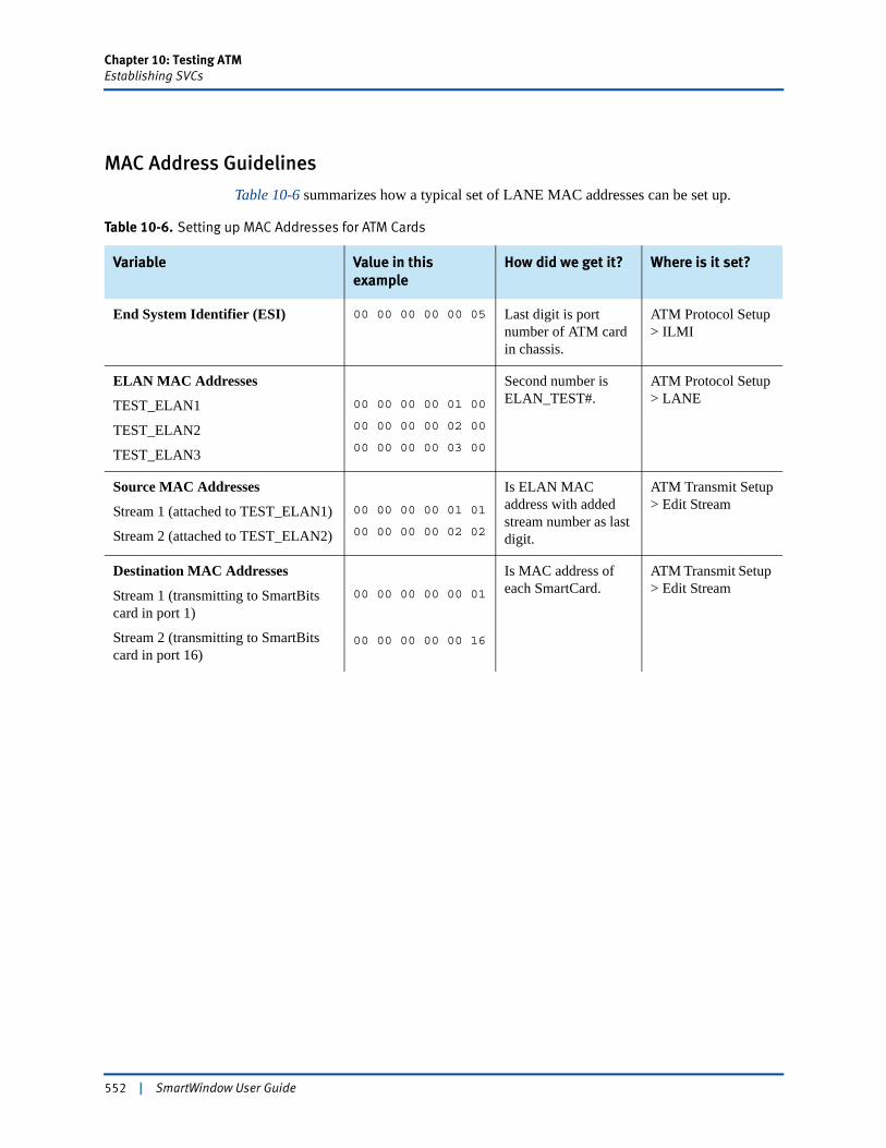
Chapter 10: Testing ATMEstablishing SVCs
MAC Address Guidelines
Table 10-6 summarizes how a typical set of LANE MAC addresses can be set up.
Table 10-6. Setting up MAC Addresses for ATM Cards
Variable Value in this example
How did we get it? Where is it set?
End System Identifier (ESI) 00 00 00 00 00 05 Last digit is port number of ATM card in chassis.
ATM Protocol Setup > ILMI
ELAN MAC Addresses
TEST_ELAN1
TEST_ELAN2
TEST_ELAN3
00 00 00 00 01 00
00 00 00 00 02 00
00 00 00 00 03 00
Second number is ELAN_TEST#.
ATM Protocol Setup> LANE
Source MAC Addresses
Stream 1 (attached to TEST_ELAN1)
Stream 2 (attached to TEST_ELAN2)
00 00 00 00 01 01
00 00 00 00 02 02
Is ELAN MAC address with added stream number as last digit.
ATM Transmit Setup> Edit Stream
Destination MAC Addresses
Stream 1 (transmitting to SmartBits card in port 1)
Stream 2 (transmitting to SmartBits card in port 16)
00 00 00 00 00 01
00 00 00 00 00 16
Is MAC address of each SmartCard.
ATM Transmit Setup > Edit Stream
552 | SmartWindow User Guide
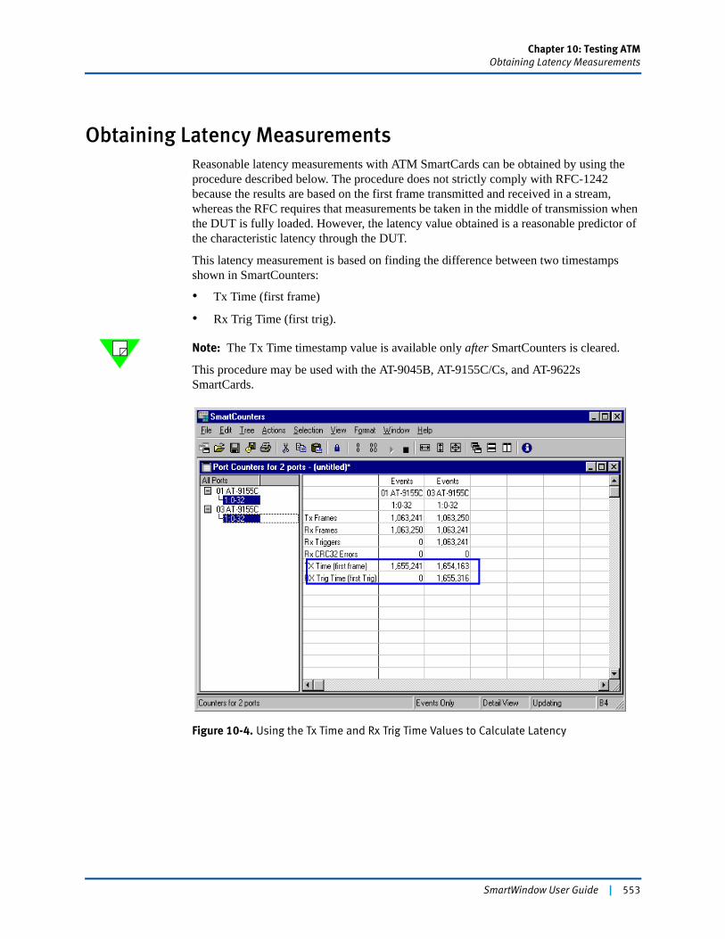
Chapter 10: Testing ATMObtaining Latency Measurements
Obtaining Latency MeasurementsReasonable latency measurements with ATM SmartCards can be obtained by using the procedure described below. The procedure does not strictly comply with RFC-1242 because the results are based on the first frame transmitted and received in a stream, whereas the RFC requires that measurements be taken in the middle of transmission when the DUT is fully loaded. However, the latency value obtained is a reasonable predictor of the characteristic latency through the DUT.
This latency measurement is based on finding the difference between two timestamps shown in SmartCounters:
• Tx Time (first frame)
• Rx Trig Time (first trig).
Note: The Tx Time timestamp value is available only after SmartCounters is cleared.
This procedure may be used with the AT-9045B, AT-9155C/Cs, and AT-9622s SmartCards.
Figure 10-4. Using the Tx Time and Rx Trig Time Values to Calculate Latency
SmartWindow User Guide | 553
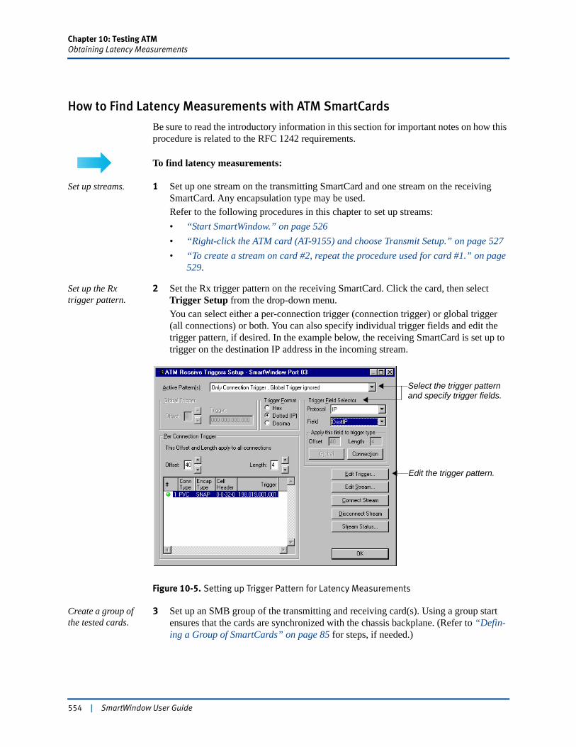
Chapter 10: Testing ATMObtaining Latency Measurements
How to Find Latency Measurements with ATM SmartCards
Be sure to read the introductory information in this section for important notes on how this procedure is related to the RFC 1242 requirements.
To find latency measurements:
Set up streams. 1 Set up one stream on the transmitting SmartCard and one stream on the receiving SmartCard. Any encapsulation type may be used.Refer to the following procedures in this chapter to set up streams:• “Start SmartWindow.” on page 526• “Right-click the ATM card (AT-9155) and choose Transmit Setup.” on page 527• “To create a stream on card #2, repeat the procedure used for card #1.” on page
529.
Set up the Rx trigger pattern.
2 Set the Rx trigger pattern on the receiving SmartCard. Click the card, then select Trigger Setup from the drop-down menu.You can select either a per-connection trigger (connection trigger) or global trigger (all connections) or both. You can also specify individual trigger fields and edit the trigger pattern, if desired. In the example below, the receiving SmartCard is set up to trigger on the destination IP address in the incoming stream.
Figure 10-5. Setting up Trigger Pattern for Latency Measurements
Create a group of the tested cards.
3 Set up an SMB group of the transmitting and receiving card(s). Using a group start ensures that the cards are synchronized with the chassis backplane. (Refer to “Defin-ing a Group of SmartCards” on page 85 for steps, if needed.)
Select the trigger patternand specify trigger fields.
Edit the trigger pattern.
554 | SmartWindow User Guide

Chapter 10: Testing ATMObtaining Latency Measurements
Connect the streams on each card.
4 Connect the streams on each card. Click the card image, then open the Transmit Setup or Trigger Setup pull-down menu. Click the stream to select it. Then click the Connect Stream button. The green LED at the left of each card comes on when the stream is connected.
Open SmartCounters and clear all counters.
5 Choose Actions > SmartCounters from the main menu to open SmartCounters. (Refer to “Set up IGMP for SmartBits 600x/6000x Modules” on page 120 for more information about SmartCounters.)
6 Choose File > New Counter Window in the SmartCounters window to display a new window listing all ports orTo display an existing file, choose File > Open.
7 Click the Clear All Counters button or choose Actions > Clear All Counters.
Start the test, then stop.
8 Click the group Start button (to the right of the SMB Group pane). Watch Smart-Counters as the test progresses.
9 Click the Stop button, and the test stops.
Note: You can customize the SmartCounters window to speed the following steps. (Refer to Figure 10-6 on page 556.)10 Select Tree > Expand All to show the stream below each port in the left pane.11 Select View > Events Only so that only events (not rates) are displayed.12 Press the <Ctrl> key and click the stream under each port (card) to select it.
Calculate the latency value.
13 To find the latency value, subtract the Tx Time (first frame) field value from the Rx Trig Time (first Trig) field value. The difference is shown in 100s of nanoseconds. Divide this value by 10 to find the final value in microseconds.Example. In the example shown in Figure 10-6 on page 556, the calculation is as fol-lows:Rx Trig Time (first Trig) 1655316Tx Time (first frame) – 165524175Divided by 10= 7.5 microseconds
Connect the stream on each card.
Green LEDcomes on whenstream isconnected.
SmartWindow User Guide | 555
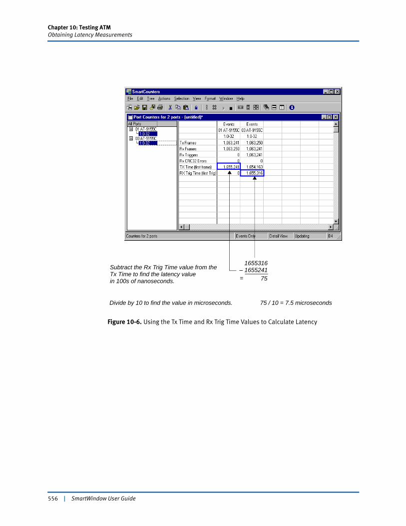
Chapter 10: Testing ATMObtaining Latency Measurements
Figure 10-6. Using the Tx Time and Rx Trig Time Values to Calculate Latency
Subtract the Rx Trig Time value from theTx Time to find the latency value
1655316– 1655241
75
Divide by 10 to find the value in microseconds. 75 / 10 = 7.5 microseconds
in 100s of nanoseconds. =
556 | SmartWindow User Guide
Chapter 11
Testing POS Routers
The SmartBits system, POS modules, and the easy-to-use SmartWindow program provide a highly effective testing tool for evaluating Packet Over SONET (POS) devices.
In this chapter...
• Testing POS Routers . . . . 558
• Test Using the POS-3519As/Ar Module . . . . 560
• Test Using the POS-3500B/Bs Module . . . . 581
• Running SmartCounters . . . . 594
• Running the Sequence and Latency Test . . . . 595
SmartWindow User Guide | 557

Chapter 11: Testing POS RoutersTesting POS Routers
Testing POS RoutersSONET and its European cousin Synchronous Digital Hierarchy (SDH) are octet-synchronous multiplexing schemes that define a family of standard rates and formats. Transmission rates are integral multiples of 51.840 Mbps.
• OC-3c/STM-1 155.520 Mbps
• OC-12c/STM-4 622.080 Mbps
• OC-48c/STM-16 2488.320 Mbps
• OC-192c/STM-64 9.953 Gbps
SONET/SDH is a perfect match for Point-to-Point Protocol (PPP). The PPP octet stream is mapped into the SONET/SDH Synchronous Payload Envelope (SPE) with the octet boundaries aligned to the SPE octet boundaries, enabling the seamless integration within IP networks of SONET/SDH routers and IP network elements.
Figure 11-1 illustrates a SmartBits 6000x equipped with two POS-3519As/AR modules used to send and receive test traffic through a POS router.
Figure 11-1. POS Router Testing Topology
POS Router
T1/E1/DS3 Frame Relay
10/100 Mbps
SmartBits 6000x with POS-3519As/AR Modules
OC-48c POS
To ML-7710
OC-48c POS
Ethernet
and LAN-3200A/AS Modules Installed
558 | SmartWindow User Guide

Chapter 11: Testing POS RoutersTesting POS Routers
Testing QOS for POS
Important benchmark tests for a POS router with a SONET interface include determining throughput in terms of packet sequencing, latency, latency distribution, and capacity. However, the overall objective is to test the QOS capabilities of the router.
Table 11-1 outlines the test methodology for this example.
Frame Sizes Supported
When more than one stream is configured, SmartWindow supports a minimum frame size of 42 bytes (exclusive of CRC) and a maximum frame size of 16,384 bytes. (SmartLibrary supports 64K bytes.) You can set the payload bytes of each frame to be filled with a user-defined content (AA, 55, FF, etc.) or with a random pattern generated for each frame.
Frames are constructed as shown below. The SmartBits Data Integrity CRC-16 covers the SmartBits Data Integrity Byte Count and Payload fields. The SmartBits frame length (without FCS) extends from after the initial HDLC Flag to the end of the SmartBits Signature Field.
Table 11-1. POS Test Methodology
Step Objective
1 Configure the SONET port interface for PPP.
2 Configure the POS card with five streams. Each stream represents a different Quality of Service (QOS) level and is capable of cycling millions of IP addresses.
3 Configure the DUT to match the POS card.
4 Run the Sequence and Latency test.
5 Using MS Excel, view results in histogram format.
1 4 20 8 8 2
HDLC Flag
PPP orCisco HDLCHeader
IP Header UDP HeaderSmartBits
Data Integrity Marker
SmartBits Data
Integer Byte
Count
>>>>
Variable 2 18 2 or 4 1
>>>>
User Payload
SmartBits Data
Integer CRC-16
SmartBits Signature FieldPPP
CRC-16 orCRC-32
HDLC Flag
SmartWindow User Guide | 559

Chapter 11: Testing POS RoutersTest Using the POS-3519As/Ar Module
Test Using the POS-3519As/AR ModuleThis section outlines the steps to test QOS for POS using the POS-3519As/AR OC-192c/STM-64 TeraMetrics module (or the equivalent POS-3518As/AR SmartMetrics module).
Use these modules to perform frame-level testing for POS/SDH routers at full OC-192c/STM-64 wire-rate. Both modules provide full SmartMetrics test support. In addition, the POS-3519As/AR features the TeraMetrics open architecture for SmartBits cards and systems. A TeraMetrics module includes a Pentium-class processor running Linux Version 2.2. This provides on-board processing power sufficient for network-to-application layer performance testing at 1 terabit per second system speeds. It also makes possible support for third-party test applications.
Note: This test setup uses the POS-3519As/AR. Additional cards and modules that support this test include the following:
• The POS-3518As/AR.SmartMetrics module can also be used in this test.
• For testing at the OC-48c/STM-16 rate, the POS-3505As/AR.and POS-3504As/AR.modules can be used.
Set up POS Port Parameters
To set up the port parameters:
1 Launch SmartWindow, and connect to the SmartBits 6000x chassis.
Note: See Chapter 2, “Install and Connect” for the steps to make a connection from your PC and SmartWindow to the SmartBits chassis.
2 Reserve each card to be configured. Right-click anywhere on the card image except the port button.
3 From the displayed menu, choose Reserve This Module.4 Starting with the first card, click the port button to open the card menu.
5 Choose Port Setup.The Port Setup dialog box opens. This window contains tabs to organize options for SONET/SDH, IPv4 stack and IPv6 stack configuration, and encapsulation.
To reserve a card, right-click anywhere onthe card image except on the port button.
After the card is reserved, clickthe port button to open thecard menu.
Select Reserve This Module.
560 | SmartWindow User Guide
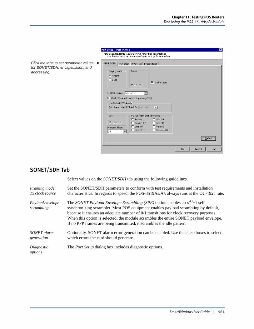
Chapter 11: Testing POS RoutersTest Using the POS-3519As/Ar Module
SONET/SDH Tab
Select values on the SONET/SDH tab using the following guidelines.
Framing mode, Tx clock source
Set the SONET/SDH parameters to conform with test requirements and installation characteristics. In regards to speed, the POS-3519As/AR always runs at the OC-192c rate.
Payload envelope scrambling
The SONET Payload Envelope Scrambling (SPE) option enables an x43+1 self-synchronizing scrambler. Most POS equipment enables payload scrambling by default, because it ensures an adequate number of 0/1 transitions for clock recovery purposes. When this option is selected, the module scrambles the entire SONET payload envelope. If no PPP frames are being transmitted, it scrambles the idle pattern.
SONET alarm generation
Optionally, SONET alarm error generation can be enabled. Use the checkboxes to select which errors the card should generate.
Diagnostic options
The Port Setup dialog box includes diagnostic options.
Click the tabs to set parameter values for SONET/SDH, encapsulation, and addressing.
SmartWindow User Guide | 561
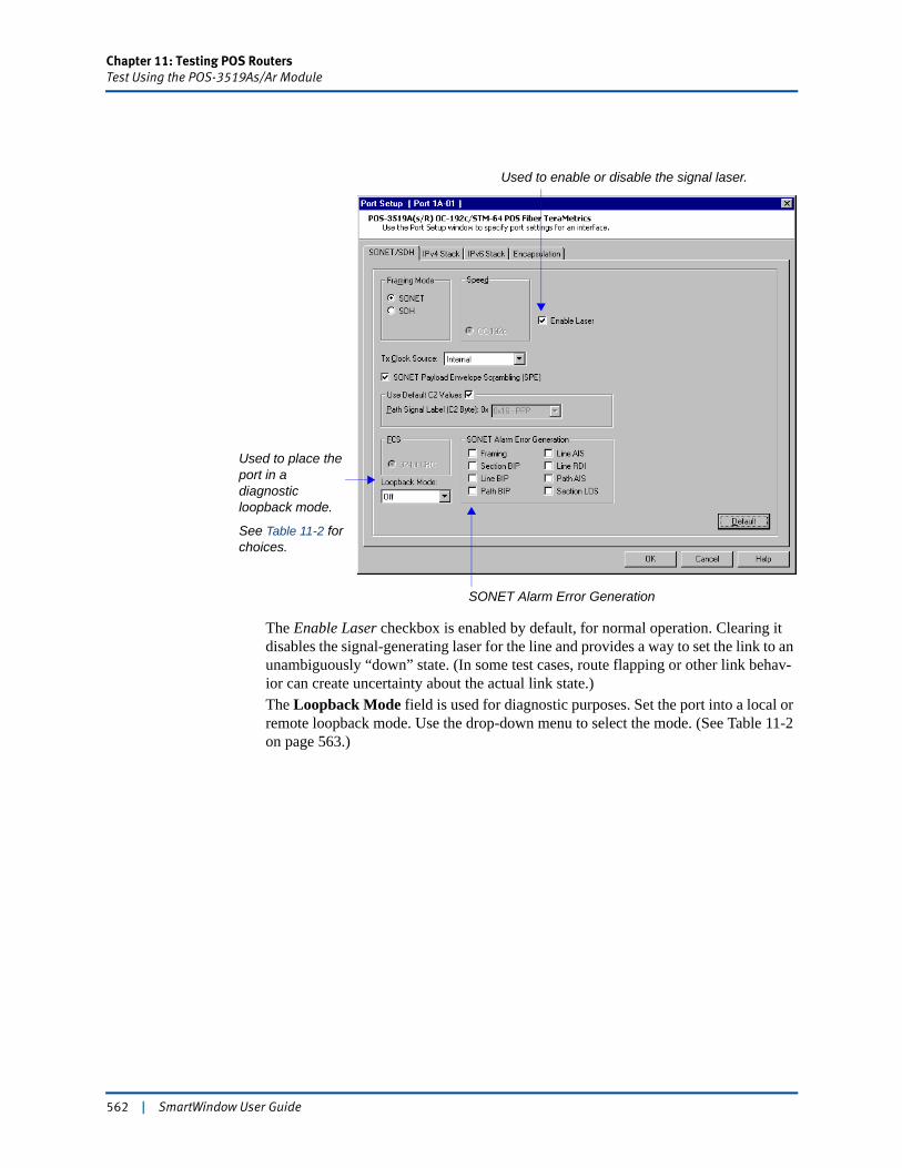
Chapter 11: Testing POS RoutersTest Using the POS-3519As/Ar Module
The Enable Laser checkbox is enabled by default, for normal operation. Clearing it disables the signal-generating laser for the line and provides a way to set the link to an unambiguously “down” state. (In some test cases, route flapping or other link behav-ior can create uncertainty about the actual link state.)The Loopback Mode field is used for diagnostic purposes. Set the port into a local or remote loopback mode. Use the drop-down menu to select the mode. (See Table 11-2 on page 563.)
Used to place the port in a diagnostic loopback mode.
See Table 11-2 for choices.
Used to enable or disable the signal laser.
SONET Alarm Error Generation
562 | SmartWindow User Guide
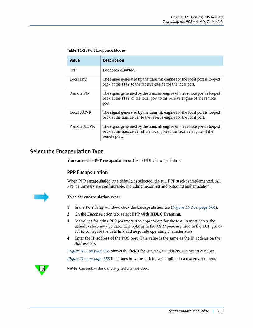
Chapter 11: Testing POS RoutersTest Using the POS-3519As/Ar Module
Select the Encapsulation Type
You can enable PPP encapsulation or Cisco HDLC encapsulation.
PPP Encapsulation
When PPP encapsulation (the default) is selected, the full PPP stack is implemented. All PPP parameters are configurable, including incoming and outgoing authentication.
To select encapsulation type:
1 In the Port Setup window, click the Encapsulation tab (Figure 11-2 on page 564).2 On the Encapsulation tab, select PPP with HDLC Framing.3 Set values for other PPP parameters as appropriate for the test. In most cases, the
default values may be used. The options in the MRU pane are used in the LCP proto-col to configure the data link and negotiate operating characteristics.
4 Enter the IP address of the POS port. This value is the same as the IP address on the Address tab.
Figure 11-3 on page 565 shows the fields for entering IP addresses in SmartWindow.
Figure 11-4 on page 565 illustrates how these fields are applied in a test environment.
Note: Currently, the Gateway field is not used.
Table 11-2. Port Loopback Modes
Value Description
Off Loopback disabled.
Local Phy The signal generated by the transmit engine for the local port is looped back at the PHY to the receive engine for the local port.
Remote Phy The signal generated by the transmit engine of the remote port is looped back at the PHY of the local port to the receive engine of the remote port.
Local XCVR The signal generated by the transmit engine for the local port is looped back at the transceiver to the receive engine for the local port.
Remote XCVR The signal generated by the transmit engine of the remote port is looped back at the transceiver of the local port to the receive engine of the remote port.
SmartWindow User Guide | 563

Chapter 11: Testing POS RoutersTest Using the POS-3519As/Ar Module
Figure 11-2. Selecting the Encapsulation Type
564 | SmartWindow User Guide
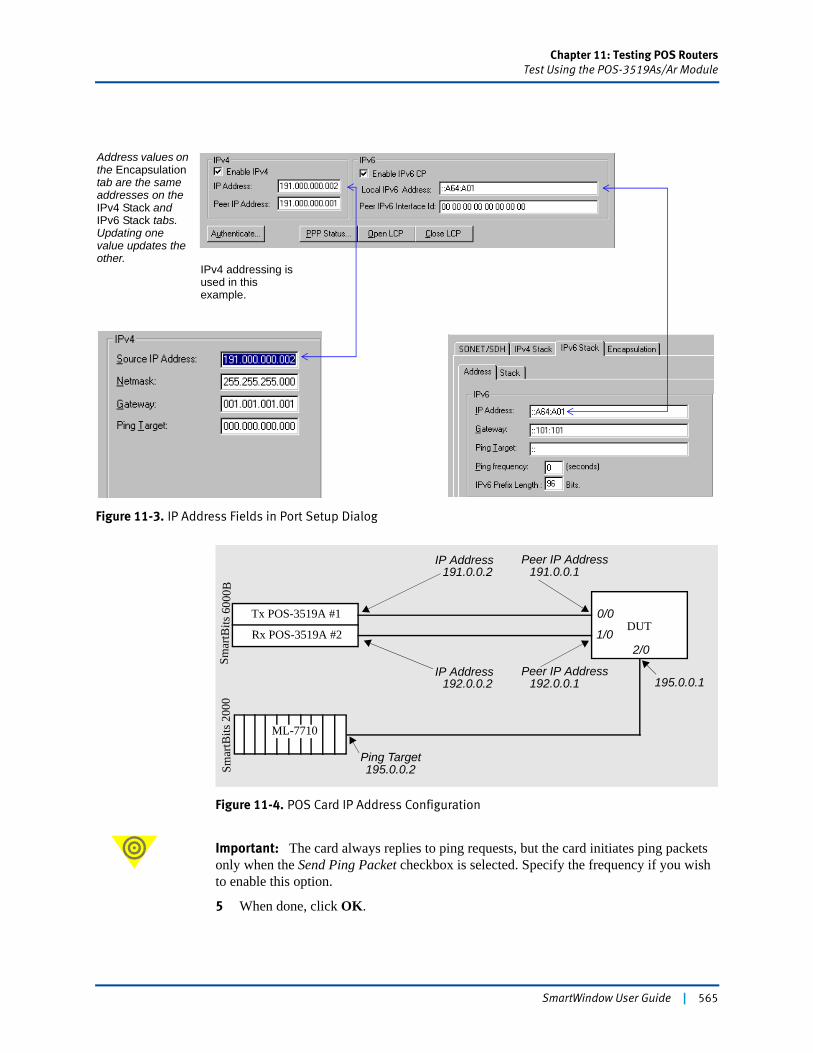
Chapter 11: Testing POS RoutersTest Using the POS-3519As/Ar Module
Figure 11-3. IP Address Fields in Port Setup Dialog
Figure 11-4. POS Card IP Address Configuration
Important: The card always replies to ping requests, but the card initiates ping packets only when the Send Ping Packet checkbox is selected. Specify the frequency if you wish to enable this option.
5 When done, click OK.
Address values on the Encapsulation tab are the same addresses on the IPv4 Stack and IPv6 Stack tabs. Updating one value updates the other.
IPv4 addressing is used in this example.
Smar
tBits
600
0BSm
artB
its 2
000
Tx POS-3519A #1
ML-7710
DUT
IP Address
Peer IP Address
Ping Target
191.0.0.2
192.0.0.1
195.0.0.2
Rx POS-3519A #2
IP Address192.0.0.2
Peer IP Address191.0.0.1
0/0
1/02/0
195.0.0.1
SmartWindow User Guide | 565
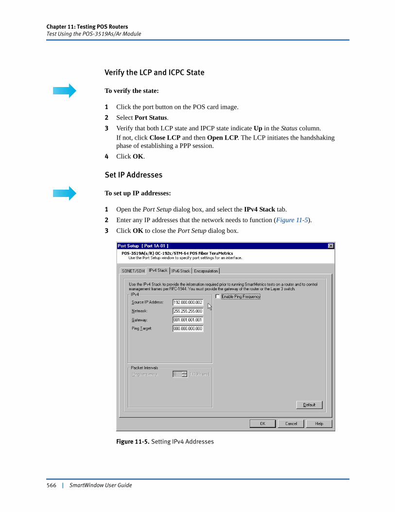
Chapter 11: Testing POS RoutersTest Using the POS-3519As/Ar Module
Verify the LCP and ICPC State
To verify the state:
1 Click the port button on the POS card image.2 Select Port Status.3 Verify that both LCP state and IPCP state indicate Up in the Status column.
If not, click Close LCP and then Open LCP. The LCP initiates the handshaking phase of establishing a PPP session.
4 Click OK.
Set IP Addresses
To set up IP addresses:
1 Open the Port Setup dialog box, and select the IPv4 Stack tab. 2 Enter any IP addresses that the network needs to function (Figure 11-5).3 Click OK to close the Port Setup dialog box.
Figure 11-5. Setting IPv4 Addresses
566 | SmartWindow User Guide
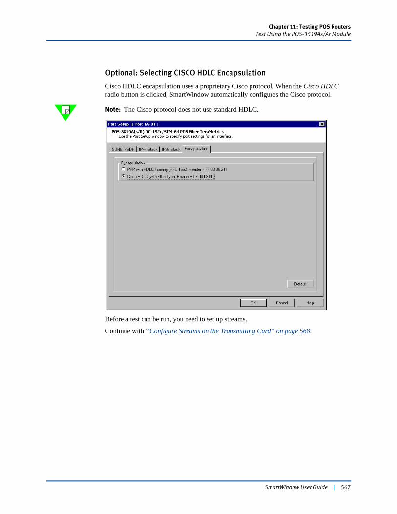
Chapter 11: Testing POS RoutersTest Using the POS-3519As/Ar Module
Optional: Selecting CISCO HDLC Encapsulation
Cisco HDLC encapsulation uses a proprietary Cisco protocol. When the Cisco HDLC radio button is clicked, SmartWindow automatically configures the Cisco protocol.
Note: The Cisco protocol does not use standard HDLC.
Before a test can be run, you need to set up streams.
Continue with “Configure Streams on the Transmitting Card” on page 568.
SmartWindow User Guide | 567
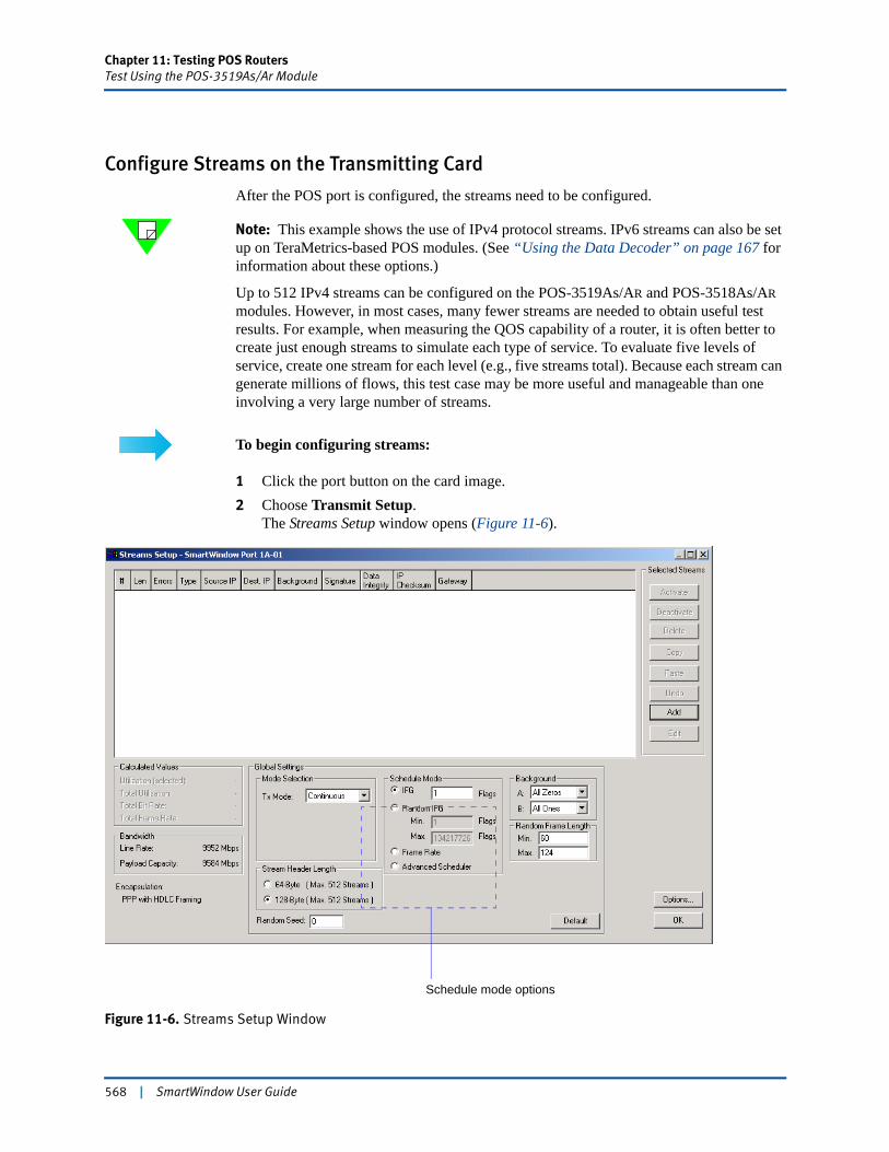
Chapter 11: Testing POS RoutersTest Using the POS-3519As/Ar Module
Configure Streams on the Transmitting Card
After the POS port is configured, the streams need to be configured.
Note: This example shows the use of IPv4 protocol streams. IPv6 streams can also be set up on TeraMetrics-based POS modules. (See “Using the Data Decoder” on page 167 for information about these options.)
Up to 512 IPv4 streams can be configured on the POS-3519As/AR and POS-3518As/AR modules. However, in most cases, many fewer streams are needed to obtain useful test results. For example, when measuring the QOS capability of a router, it is often better to create just enough streams to simulate each type of service. To evaluate five levels of service, create one stream for each level (e.g., five streams total). Because each stream can generate millions of flows, this test case may be more useful and manageable than one involving a very large number of streams.
To begin configuring streams:
1 Click the port button on the card image. 2 Choose Transmit Setup.
The Streams Setup window opens (Figure 11-6).
Figure 11-6. Streams Setup Window
Schedule mode options
568 | SmartWindow User Guide
Chapter 11: Testing POS RoutersTest Using the POS-3519As/Ar Module
Schedule Mode
The Global Settings pane of the Streams Setup window provides options for defining how the card schedules the streams that it transmits. Use these options before adding the streams, since these settings apply to the port overall.
In the Schedule Mode pane of the Global Settings pane (Figure 11-6 on page 568), there are four options for scheduling:
• IFG — Interframe Gap: a fixed number of bit times between frames
• Random IFG — A varying number of bit times between frames
• Frame Rate — A defined frames-per-second rate of transmission for each stream
• Advanced Scheduler— A scheduling of frames (using frame rate) based on a balanced mix that results in a smoother distribution of traffic between flows. This capability requires firmware 5.50 or later and is supported on LAN-3306A, LAN-332xA, POS-3504As/AR, POS-3505As/AR, POS-3510A/As, POS-3511A/As, POS-3518As/AR, POS-3519As/AR, XLW-372xA, XFP-373xA, and FBC-360xA modules.
The selected scheduling mode applies to all streams for the port. However, when frame rate or advanced scheduler is selected as the mode, a different rate can be specified for each stream. (With traffic based on fixed interframe gap, the specified gap applies to all streams.) Once the mode is specified, use the Add button to open the Add Streams window, which allows you to create one or multiple streams.
How Does Scheduling Work?
TeraMetrics cards include a software mechanism, called the scheduler, that calculates how to allocate line bandwidth to the streams that have been created.
For all four scheduling options, the scheduler calculates a scheduling table that organizes all streams for transmission before any traffic is sent. The schedule table is static—it does not vary as test traffic is sent—even though three of the scheduling options (Random IFG, Frame Rate, and Advanced Scheduler) appear to be dynamic in behavior because individual stream frame rates and random interframe gaps are allowed.
Gap-based Traffic
The two gap modes (IFG and Random IFG) belong in the same category. With each mode, the frame size and gap size (or range of gap sizes) are controlled, but not the frame rate.
With IFG mode, the card inserts the specified gap (i.e., number of bit times) between frames. It then sends out test traffic, with the selected frame size, at the maximum line rate.
With random IFG mode, a random number generator on the card produces gaps of varying sizes, within the bounds that were defined using the Min. and Max. fields in the Streams Setup window. These gaps are inserted between frames. Then test traffic is sent with the selected frame size at the maximum line rate.
SmartWindow User Guide | 569
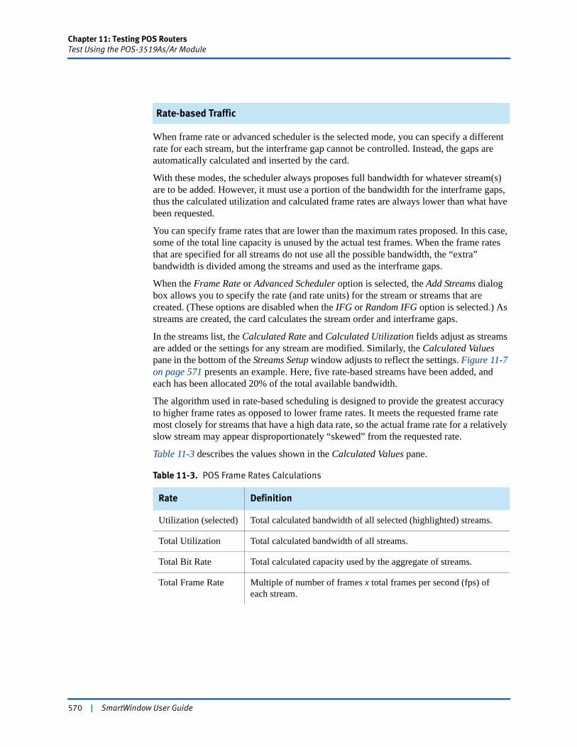
Chapter 11: Testing POS RoutersTest Using the POS-3519As/Ar Module
Rate-based Traffic
When frame rate or advanced scheduler is the selected mode, you can specify a different rate for each stream, but the interframe gap cannot be controlled. Instead, the gaps are automatically calculated and inserted by the card.
With these modes, the scheduler always proposes full bandwidth for whatever stream(s) are to be added. However, it must use a portion of the bandwidth for the interframe gaps, thus the calculated utilization and calculated frame rates are always lower than what have been requested.
You can specify frame rates that are lower than the maximum rates proposed. In this case, some of the total line capacity is unused by the actual test frames. When the frame rates that are specified for all streams do not use all the possible bandwidth, the “extra” bandwidth is divided among the streams and used as the interframe gaps.
When the Frame Rate or Advanced Scheduler option is selected, the Add Streams dialog box allows you to specify the rate (and rate units) for the stream or streams that are created. (These options are disabled when the IFG or Random IFG option is selected.) As streams are created, the card calculates the stream order and interframe gaps.
In the streams list, the Calculated Rate and Calculated Utilization fields adjust as streams are added or the settings for any stream are modified. Similarly, the Calculated Values pane in the bottom of the Streams Setup window adjusts to reflect the settings. Figure 11-7 on page 571 presents an example. Here, five rate-based streams have been added, and each has been allocated 20% of the total available bandwidth.
The algorithm used in rate-based scheduling is designed to provide the greatest accuracy to higher frame rates as opposed to lower frame rates. It meets the requested frame rate most closely for streams that have a high data rate, so the actual frame rate for a relatively slow stream may appear disproportionately “skewed” from the requested rate.
Table 11-3 describes the values shown in the Calculated Values pane.
Table 11-3. POS Frame Rates Calculations
Rate Definition
Utilization (selected) Total calculated bandwidth of all selected (highlighted) streams.
Total Utilization Total calculated bandwidth of all streams.
Total Bit Rate Total calculated capacity used by the aggregate of streams.
Total Frame Rate Multiple of number of frames x total frames per second (fps) of each stream.
570 | SmartWindow User Guide

Chapter 11: Testing POS RoutersTest Using the POS-3519As/Ar Module
Figure 11-7. Frame Scheduling Based on Frame Rate
When Schedule Mode is set to Frame Rate or Advanced Scheduler, these fields show the total calculated frame rates and percentages for all streams that have been added.
As streams are created, SmartWindow calculates the individual and total frame rates for the card, as well as interframe gaps. (See Table 11-3, “POS Frame Rates Calculations,” on page 570.)
These fields appear when frame rate is selected as the scheduling mode.
SmartWindow User Guide | 571
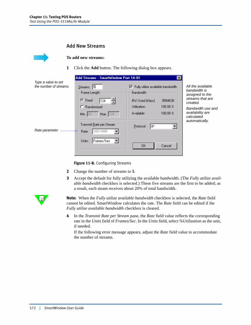
Chapter 11: Testing POS RoutersTest Using the POS-3519As/Ar Module
Add New Streams
To add new streams:
1 Click the Add button. The following dialog box appears.
Figure 11-8. Configuring Streams
2 Change the number of streams to 5.3 Accept the default for fully utilizing the available bandwidth. (The Fully utilize avail-
able bandwidth checkbox is selected.) These five streams are the first to be added; as a result, each steam receives about 20% of total bandwidth.
Note: When the Fully utilize available bandwidth checkbox is selected, the Rate field cannot be edited. SmartWindow calculates the rate. The Rate field can be edited if the Fully utilize available bandwidth checkbox is cleared.
4 In the Transmit Rate per Stream pane, the Rate field value reflects the corresponding rate in the Units field of Frames/Sec. In the Units field, select %Utilization as the unit, if needed.If the following error message appears, adjust the Rate field value to accommodate the number of streams.
Type a value to setthe number of streams. All the available
bandwidth is assigned to the streams that are created.Bandwidth use and availability are calculated automatically.
Rate parameter 1857488
572 | SmartWindow User Guide
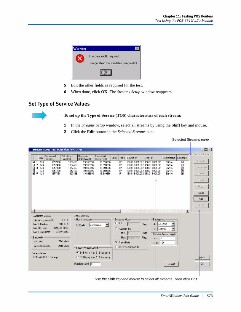
Chapter 11: Testing POS RoutersTest Using the POS-3519As/Ar Module
5 Edit the other fields as required for the test. 6 When done, click OK. The Streams Setup window reappears.
Set Type of Service Values
To set up the Type of Service (TOS) characteristics of each stream:
1 In the Streams Setup window, select all streams by using the Shift key and mouse.2 Click the Edit button in the Selected Streams pane.
Use the Shift key and mouse to select all streams. Then click Edit.
Selected Streams pane
SmartWindow User Guide | 573

Chapter 11: Testing POS RoutersTest Using the POS-3519As/Ar Module
3 In the Edit Protocol Stack pane, click the Layer 3: IP button. The Setup:IP (Internet Protocol) view opens in the right pane.
4 In the Type of Service (TOS) pane, set Type of Service to 92. Notice that doing this automatically adjusts the value for Precedence and TOS Bits options, though these options remain greyed out.
5 Click Details to make these fields active. The edit mode reverses: the Service Type field becomes greyed out, and the Precedence and TOS options can be set explicitly. Now the Service Type field varies automatically (though still greyed out) in response to the Precedence value that is set and the TOS checkboxes that are enabled.The MBZ checkbox toggles the least-significant bit in the TOS octet. This bit is labeled MBZ for “must be zero.” It is currently unused in normal IP routing, but it may be set for experimental purposes. Normally, the originator of a datagram sets this field to zero. Routers and recipients of datagrams ignore this field value. This field is copied on fragmentation.
Click IP to open the SETUP pane for IP parameters.
574 | SmartWindow User Guide
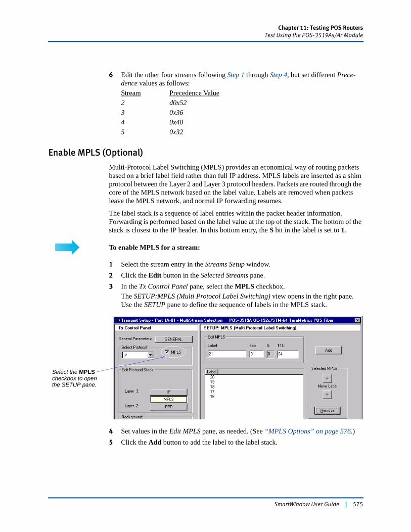
Chapter 11: Testing POS RoutersTest Using the POS-3519As/Ar Module
6 Edit the other four streams following Step 1 through Step 4, but set different Prece-dence values as follows:Stream Precedence Value2 d0x523 0x364 0x405 0x32
Enable MPLS (Optional)
Multi-Protocol Label Switching (MPLS) provides an economical way of routing packets based on a brief label field rather than full IP address. MPLS labels are inserted as a shim protocol between the Layer 2 and Layer 3 protocol headers. Packets are routed through the core of the MPLS network based on the label value. Labels are removed when packets leave the MPLS network, and normal IP forwarding resumes.
The label stack is a sequence of label entries within the packet header information. Forwarding is performed based on the label value at the top of the stack. The bottom of the stack is closest to the IP header. In this bottom entry, the S bit in the label is set to 1.
To enable MPLS for a stream:
1 Select the stream entry in the Streams Setup window.2 Click the Edit button in the Selected Streams pane.3 In the Tx Control Panel pane, select the MPLS checkbox.
The SETUP:MPLS (Multi Protocol Label Switching) view opens in the right pane. Use the SETUP pane to define the sequence of labels in the MPLS stack.
4 Set values in the Edit MPLS pane, as needed. (See “MPLS Options” on page 576.)5 Click the Add button to add the label to the label stack.
Select the MPLS checkbox to open the SETUP pane.
SmartWindow User Guide | 575
Chapter 11: Testing POS RoutersTest Using the POS-3519As/Ar Module
Note: Up to 11 MPLS labels can be added in a frame definition.
Use the buttons in the Selected MPLS pane to move label entries up and down in the stack, or to delete entries from the stack.
All values can be reset by selecting the Default button.
MPLS Options
MPLS options in the Setup:MPLS (Multi Protocol Label Switching) pane include the following:
Label fieldThis 20-bit field is a flow identifier and is unique within a port (i.e., no two flows on the same port use the same label). A packet label value is changed with each hop toward the destination.
Exp (experimental) fieldThis field is reserved for future use. However, many devices use it for Class of Service (COS) identification.
S (bottom of stack indication) fieldSet to 1 to indicate bottom of label stack.
TTL (time-to-live) fieldThe time-to-live value for the IP packet.
576 | SmartWindow User Guide
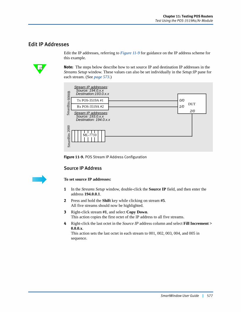
Chapter 11: Testing POS RoutersTest Using the POS-3519As/Ar Module
Edit IP Addresses
Edit the IP addresses, referring to Figure 11-9 for guidance on the IP address scheme for this example.
Note: The steps below describe how to set source IP and destination IP addresses in the Streams Setup window. These values can also be set individually in the Setup:IP pane for each stream. (See page 573.)
Figure 11-9. POS Stream IP Address Configuration
Source IP Address
To set source IP addresses:
1 In the Streams Setup window, double-click the Source IP field, and then enter the address 194.0.0.1.
2 Press and hold the Shift key while clicking on stream #5. All five streams should now be highlighted.
3 Right-click stream #1, and select Copy Down. This action copies the first octet of the IP address to all five streams.
4 Right-click the last octet in the Source IP address column and select Fill Increment > 0.0.0.x. This action sets the last octet in each stream to 001, 002, 003, 004, and 005 in sequence.
Smar
tBits
600
0BSm
artB
its 2
000
Tx POS-3519A #1
ML-7710
DUTRx POS-3519A #2
Stream IP addresses:Source: 194.0.x.xDestination:193.0.x.x
Stream IP addresses:Source: 193.0.x.xDestination: 194.0.x.x
0/0
1/02/0
SmartWindow User Guide | 577
Chapter 11: Testing POS RoutersTest Using the POS-3519As/Ar Module
Destination IP Address
To set destination IP addresses:
1 Repeat Step 1 on page 577 through Step 4 on page 577, but use the Dest. IP field in the Streams Setup window.
2 Set addresses to 193.0.0.1 through 193.0.0.5.
Set up Flows for Each Stream
Each stream can be configured to cycle through up to 16,777,215 flows (for IP protocol streams) or 65,535 flows (for UDP or TCP protocol streams).
With IP streams, flow generation can be based on IP source or destination address or on VFD fields. With UDP or TCP streams, flow generation can be based on these IP address values as well as on source or destination port number.
To set up flows for each stream:
1 Select (click) the stream in the Streams Setup window.2 Click the Edit button.3 In the Flow Generation pane located in the Tx Control Panel pane, select the variable
to use with Flow 1.The Setup view changes to show the associated options. For example, in Figure 11-10 on page 579, the selected protocol is IP and the generation variable for Flow 1 is IP ADDR. SOURCE.
4 Set values in the related Setup view to suit the flow generation variable that was selected.
Note: See “When Setting up IP Flows” on page 579 for guidelines on setting up flows for IP protocol streams and for UDP or TCP protocol streams.
578 | SmartWindow User Guide
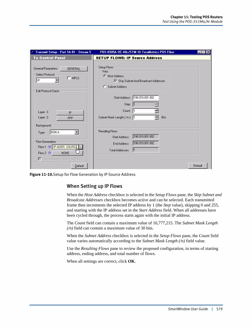
Chapter 11: Testing POS RoutersTest Using the POS-3519As/Ar Module
Figure 11-10.Setup for Flow Generation by IP Source Address
When Setting up IP Flows
When the Host Address checkbox is selected in the Setup Flows pane, the Skip Subnet and Broadcast Addresses checkbox becomes active and can be selected. Each transmitted frame then increments the selected IP address by 1 (the Step value), skipping 0 and 255, and starting with the IP address set in the Start Address field. When all addresses have been cycled through, the process starts again with the initial IP address.
The Count field can contain a maximum value of 16,777,215. The Subnet Mask Length (/n) field can contain a maximum value of 30 bits.
When the Subnet Address checkbox is selected in the Setup Flows pane, the Count field value varies automatically according to the Subnet Mask Length (/n) field value.
Use the Resulting Flows pane to review the proposed configuration, in terms of starting address, ending address, and total number of flows.
When all settings are correct, click OK.
SmartWindow User Guide | 579
Chapter 11: Testing POS RoutersTest Using the POS-3519As/Ar Module
When Setting up Layer 4 Flows (UDP or TCP)
Select SOURCE PORT or DEST. PORT as the flow generation variable only when a Layer 4 protocol (UDP or TCP) has been selected in the Select Protocol field.
The Source Port and Destination Port fields each can contain a maximum value of 65535. The Subnet Mask Length (/n) field can contain a maximum value of 30 bits.
When all settings are correct, click OK.
Send the Configuration to the Cards
Click the Update button in the SmartWindow toolbar to copy your configuration to the card, or select Actions > Update from the main menu.
! Caution: When the card is updated, the PPP link automatically renegotiates.
To configure the line interface and IP addresses of the receiving card, see “Configuring a Card to Receive”.
Configuring a Card to Receive
Streams do not need to be created on the receiving card, unless there needs to be two-way transmission and reception. However, the port interface and the IP addresses do need to be configured. Perform this action by using the procedures already described in “Set up Line Parameters” on page 582.
Use the information in Figure 11-9 on page 577 to set the card IP addresses.
Set up the DUT
Set Port IP Addresses
On the DUT, set up the port IP addresses using Figure 11-9 on page 577 as a guide.
Set Stream IP Addresses
The POS router must be able to handle the IP addresses of the streams that have been created, so the router must be configured so it can build a routing table that knows what to do with each flow.
Depending on the capabilities of the POS router, you may need to set up static routes or supernetting (i.e., assigning to each stream a different second byte in the IP address, such as 193.19.x.x, 193.20.x.x, 193.21.x.x, etc.) In this way, as the streams cycle through the frames of a flow, no frames are discarded or lost, and each stream is treated separately in SmartMetrics test results.
580 | SmartWindow User Guide

Chapter 11: Testing POS RoutersTest Using the POS-3500B/Bs Module
Get Test Results
See “Running SmartCounters” on page 594 and “Running the Sequence and Latency Test” on page 595 for the steps to retrieve counters and SmartMetrics tests results.
Test Using the POS-3500B/Bs ModuleThis section outlines the steps to test QOS for POS using the POS-3500B/Bs OC-12c/STM-4 module.
POS-3500B/Bs Features and Functions
Each POS-3500B/Bs supports one OC-12c/STM-4 port in the SmartBits 600x/6000x chassis.
These modules are capable of:
• Generating up to 8,192 streams at any time and analyzing the results.
• Implementing up to 65,535 flows per stream, for a total of 524 million flows per port.
• Testing real POS router performance with SmartMetrics tests, including per-flow Frame Loss, Latency, Latency and Sequence, and Latency Distribution tracking.
• Testing core and edge router capabilities through a fully integrated array of SmartBits SmartMetrics cards.
These cards feature:
• True 622 Mbps line rate traffic generation and analysis
• Multi-mode or single-mode fiber support
• SONET or SDH framing
• Fully independent port operation
• 1310 nm physical output/input wave length
• SONET/SDH analysis of section overhead, line overhead, and path overhead
• User-enabled SONET/SDH payload scrambling (X43+1)
• FCS: 16-bit and 32-bit CRC supported
• Encapsulation:• PPP as per RFC-1662• HDLC with Ethertype (Cisco HDLC).
SmartWindow User Guide | 581
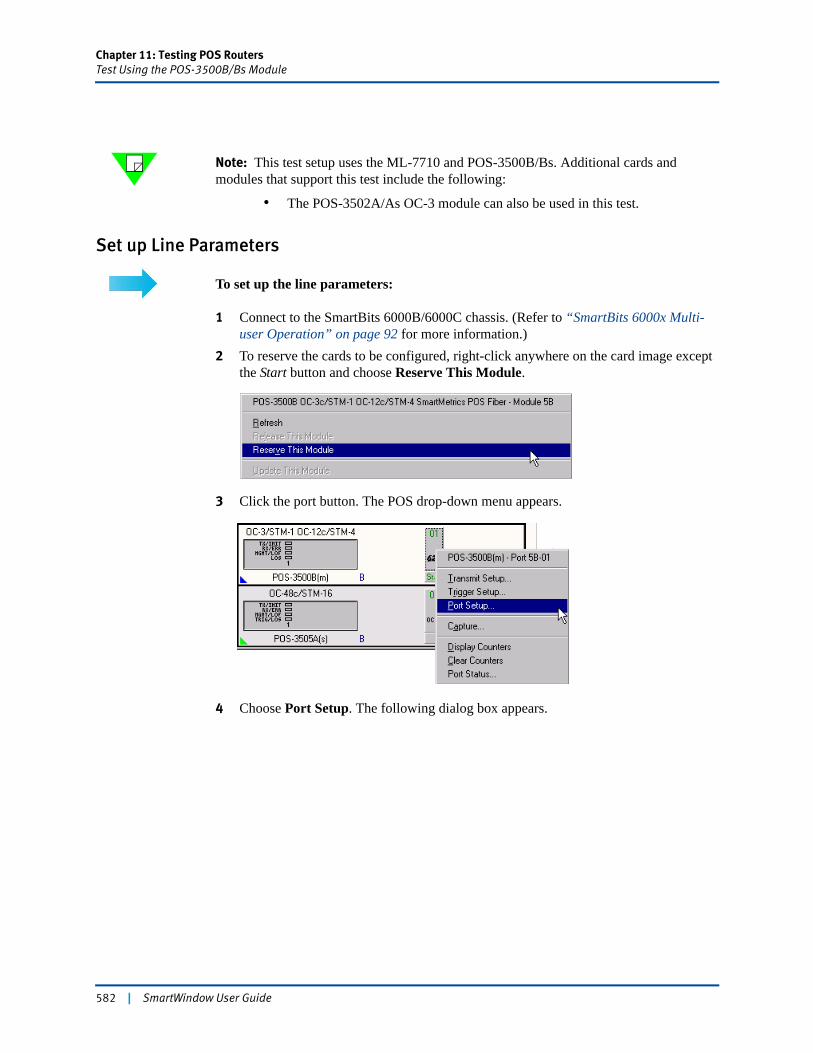
Chapter 11: Testing POS RoutersTest Using the POS-3500B/Bs Module
Note: This test setup uses the ML-7710 and POS-3500B/Bs. Additional cards and modules that support this test include the following:
• The POS-3502A/As OC-3 module can also be used in this test.
Set up Line Parameters
To set up the line parameters:
1 Connect to the SmartBits 6000B/6000C chassis. (Refer to “SmartBits 6000x Multi-user Operation” on page 92 for more information.)
2 To reserve the cards to be configured, right-click anywhere on the card image except the Start button and choose Reserve This Module.
3 Click the port button. The POS drop-down menu appears.
4 Choose Port Setup. The following dialog box appears.
582 | SmartWindow User Guide
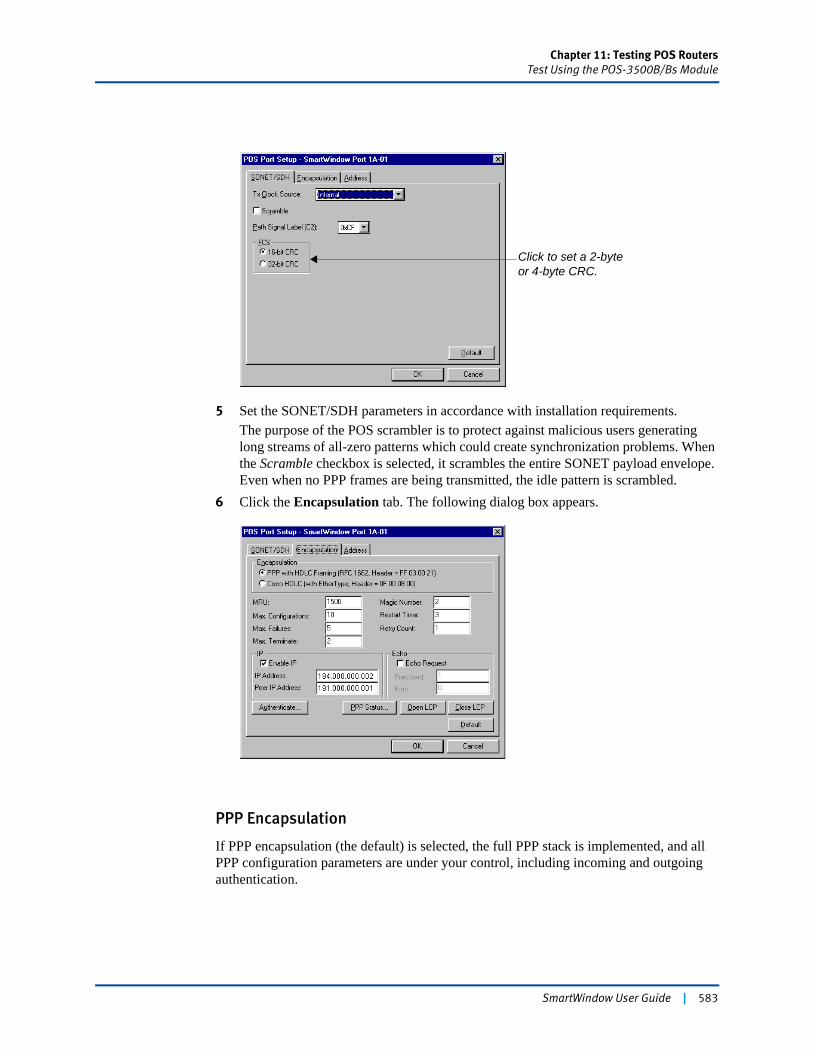
Chapter 11: Testing POS RoutersTest Using the POS-3500B/Bs Module
5 Set the SONET/SDH parameters in accordance with installation requirements.The purpose of the POS scrambler is to protect against malicious users generating long streams of all-zero patterns which could create synchronization problems. When the Scramble checkbox is selected, it scrambles the entire SONET payload envelope. Even when no PPP frames are being transmitted, the idle pattern is scrambled.
6 Click the Encapsulation tab. The following dialog box appears.
PPP Encapsulation
If PPP encapsulation (the default) is selected, the full PPP stack is implemented, and all PPP configuration parameters are under your control, including incoming and outgoing authentication.
Click to set a 2-byte or 4-byte CRC.
SmartWindow User Guide | 583
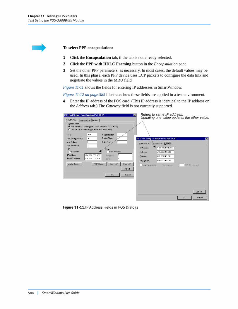
Chapter 11: Testing POS RoutersTest Using the POS-3500B/Bs Module
To select PPP encapsulation:
1 Click the Encapsulation tab, if the tab is not already selected.2 Click the PPP with HDLC Framing button in the Encapsulation pane.3 Set the other PPP parameters, as necessary. In most cases, the default values may be
used. In this phase, each PPP device uses LCP packets to configure the data link and negotiate the values in the MRU field.
Figure 11-11 shows the fields for entering IP addresses in SmartWindow.
Figure 11-12 on page 585 illustrates how these fields are applied in a test environment.4 Enter the IP address of the POS card. (This IP address is identical to the IP address on
the Address tab.) The Gateway field is not currently supported.
Figure 11-11.IP Address Fields in POS Dialogs
Updating one value updates the other value.Refers to same IP address.
584 | SmartWindow User Guide
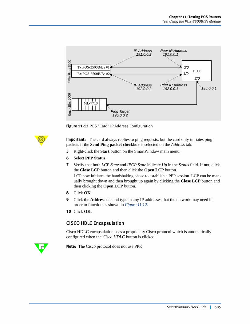
Chapter 11: Testing POS RoutersTest Using the POS-3500B/Bs Module
Figure 11-12.POS “Card” IP Address Configuration
Important: The card always replies to ping requests, but the card only initiates ping packets if the Send Ping packet checkbox is selected on the Address tab.5 Right-click the Start button on the SmartWindow main menu.6 Select PPP Status.7 Verify that both LCP State and IPCP State indicate Up in the Status field. If not, click
the Close LCP button and then click the Open LCP button.LCP now initiates the handshaking phase to establish a PPP session. LCP can be man-ually brought down and then brought up again by clicking the Close LCP button and then clicking the Open LCP button.
8 Click OK.9 Click the Address tab and type in any IP addresses that the network may need in
order to function as shown in Figure 11-12.10 Click OK.
CISCO HDLC Encapsulation
Cisco HDLC encapsulation uses a proprietary Cisco protocol which is automatically configured when the Cisco HDLC button is clicked.
Note: The Cisco protocol does not use PPP.
Smar
tBits
600
0Sm
artB
its 2
000
Tx POS-3500B/Bs #1
ML-7710
DUT
IP Address
Peer IP Address
Ping Target
191.0.0.2
192.0.0.1
195.0.0.2
Rx POS-3500B/Bs #2
IP Address192.0.0.2
Peer IP Address191.0.0.1
0/0
1/02/0
195.0.0.1
SmartWindow User Guide | 585
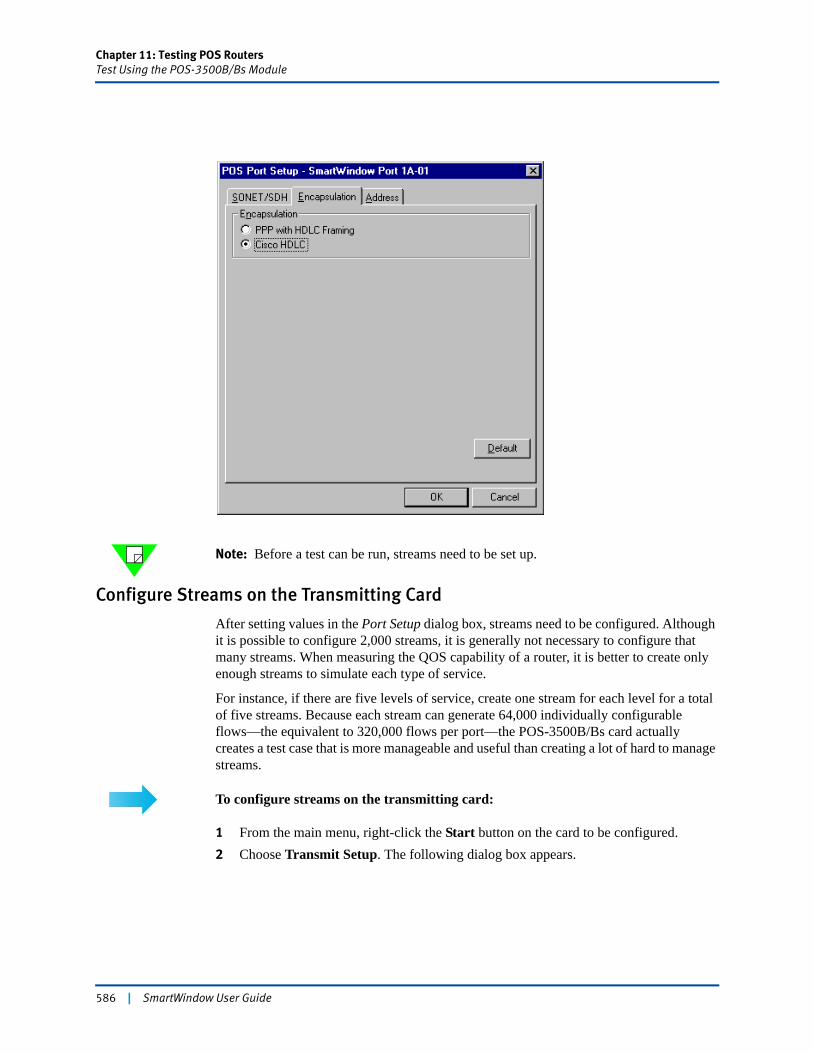
Chapter 11: Testing POS RoutersTest Using the POS-3500B/Bs Module
Note: Before a test can be run, streams need to be set up.
Configure Streams on the Transmitting Card
After setting values in the Port Setup dialog box, streams need to be configured. Although it is possible to configure 2,000 streams, it is generally not necessary to configure that many streams. When measuring the QOS capability of a router, it is better to create only enough streams to simulate each type of service.
For instance, if there are five levels of service, create one stream for each level for a total of five streams. Because each stream can generate 64,000 individually configurable flows—the equivalent to 320,000 flows per port—the POS-3500B/Bs card actually creates a test case that is more manageable and useful than creating a lot of hard to manage streams.
To configure streams on the transmitting card:
1 From the main menu, right-click the Start button on the card to be configured.2 Choose Transmit Setup. The following dialog box appears.
586 | SmartWindow User Guide
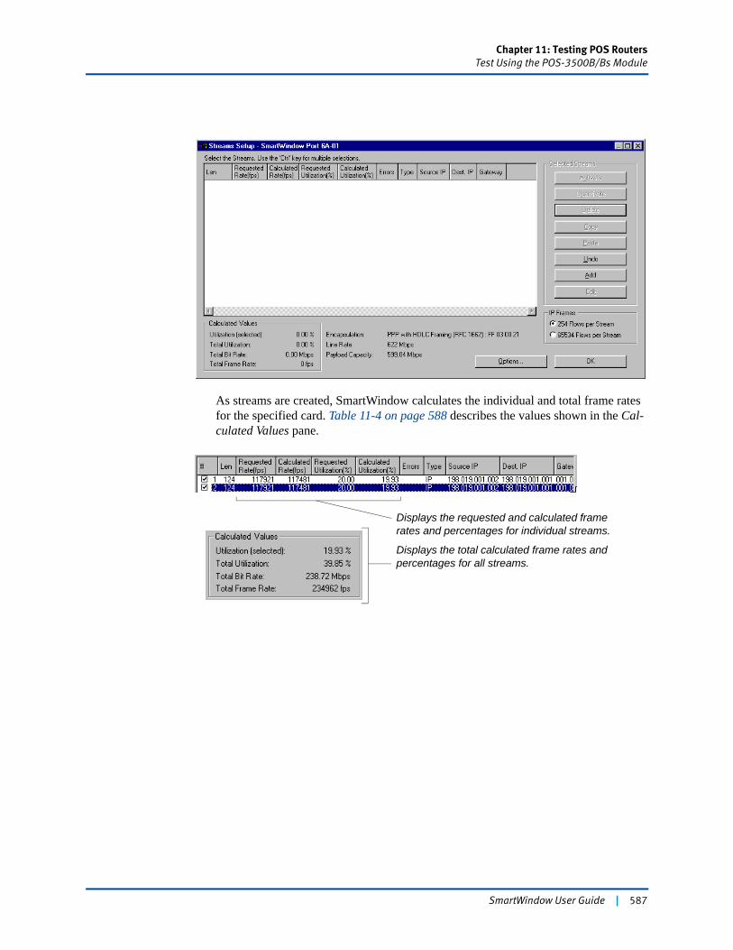
Chapter 11: Testing POS RoutersTest Using the POS-3500B/Bs Module
As streams are created, SmartWindow calculates the individual and total frame rates for the specified card. Table 11-4 on page 588 describes the values shown in the Cal-culated Values pane.
Displays the requested and calculated frame rates and percentages for individual streams.
Displays the total calculated frame rates and percentages for all streams.
SmartWindow User Guide | 587
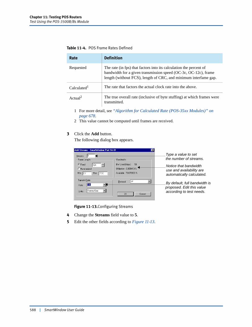
Chapter 11: Testing POS RoutersTest Using the POS-3500B/Bs Module
3 Click the Add button.The following dialog box appears.
Figure 11-13.Configuring Streams
4 Change the Streams field value to 5.5 Edit the other fields according to Figure 11-13.
Table 11-4. POS Frame Rates Defined
Rate Definition
Requested The rate (in fps) that factors into its calculation the percent of bandwidth for a given transmission speed (OC-3c, OC-12c), frame length (without FCS), length of CRC, and minimum interfame gap.
Calculated1
1 For more detail, see “Algorithm for Calculated Rate (POS-35xx Modules)” on page 678.
The rate that factors the actual clock rate into the above.
Actual2
2 This value cannot be computed until frames are received.
The true overall rate (inclusive of byte stuffing) at which frames were transmitted.
Type a value to setthe number of streams.
Notice that bandwidthuse and availability are automatically calculated.
By default, full bandwidth is proposed. Edit this valueaccording to test needs.
588 | SmartWindow User Guide
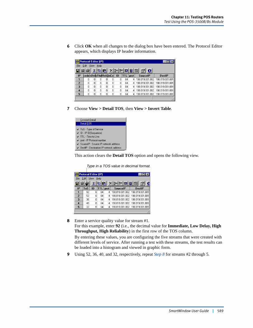
Chapter 11: Testing POS RoutersTest Using the POS-3500B/Bs Module
6 Click OK when all changes to the dialog box have been entered. The Protocol Editor appears, which displays IP header information.
7 Choose View > Detail TOS, then View > Invert Table.
This action clears the Detail TOS option and opens the following view.
8 Enter a service quality value for stream #1. For this example, enter 92 (i.e., the decimal value for Immediate, Low Delay, High Throughput, High Reliability) in the first row of the TOS column.By entering these values, you are configuring the five streams that were created with different levels of service. After running a test with these streams, the test results can be loaded into a histogram and viewed in graphic form.
9 Using 52, 36, 40, and 32, respectively, repeat Step 8 for streams #2 through 5.
Type in a TOS value in decimal format.
SmartWindow User Guide | 589
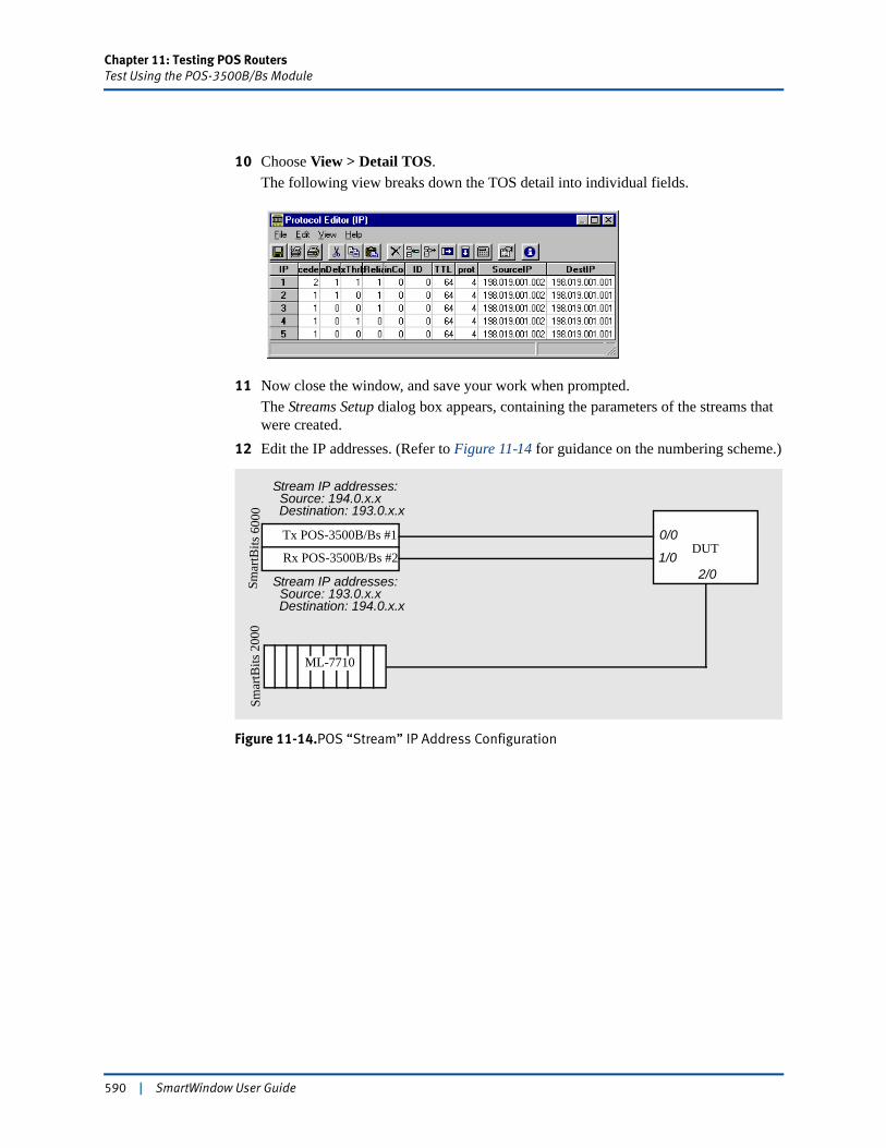
Chapter 11: Testing POS RoutersTest Using the POS-3500B/Bs Module
10 Choose View > Detail TOS.The following view breaks down the TOS detail into individual fields.
11 Now close the window, and save your work when prompted.The Streams Setup dialog box appears, containing the parameters of the streams that were created.
12 Edit the IP addresses. (Refer to Figure 11-14 for guidance on the numbering scheme.)
Figure 11-14.POS “Stream” IP Address Configuration
Smar
tBits
600
0Sm
artB
its 2
000
Tx POS-3500B/Bs #1
ML-7710
DUTRx POS-3500B/Bs #2
Stream IP addresses:Source: 194.0.x.xDestination: 193.0.x.x
Stream IP addresses:Source: 193.0.x.xDestination: 194.0.x.x
0/0
1/02/0
590 | SmartWindow User Guide
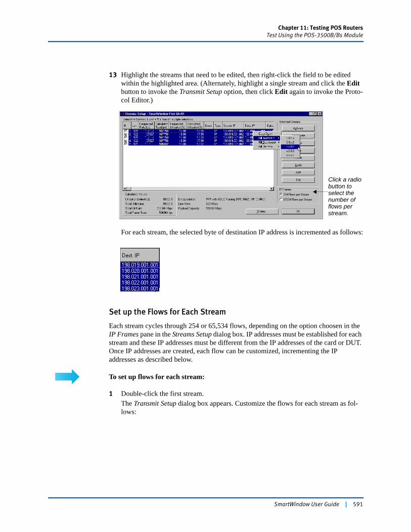
Chapter 11: Testing POS RoutersTest Using the POS-3500B/Bs Module
13 Highlight the streams that need to be edited, then right-click the field to be edited within the highlighted area. (Alternately, highlight a single stream and click the Edit button to invoke the Transmit Setup option, then click Edit again to invoke the Proto-col Editor.)
For each stream, the selected byte of destination IP address is incremented as follows:
Set up the Flows for Each Stream
Each stream cycles through 254 or 65,534 flows, depending on the option choosen in the IP Frames pane in the Streams Setup dialog box. IP addresses must be established for each stream and these IP addresses must be different from the IP addresses of the card or DUT. Once IP addresses are created, each flow can be customized, incrementing the IP addresses as described below.
To set up flows for each stream:
1 Double-click the first stream.The Transmit Setup dialog box appears. Customize the flows for each stream as fol-lows:
Click a radio button to select the number of flows per stream.
SmartWindow User Guide | 591

Chapter 11: Testing POS RoutersTest Using the POS-3500B/Bs Module
Note: If source or destination IP address is selected, each transmitted frame increments the selected IP address by 1, skipping 0 and 255 (starting with the IP address set in the Protocol Editor). When all 65,534 addresses have been cycled through, the cycling process starts again with the IP address set in the Protocol Editor.2 Make the necessary edits to each stream.
You are finished with stream and flow configuration.
3 Click OK.4 Click the Download button on the SmartWindow toolbar to copy the configuration to
the card.
! Caution: When the card is updated, the PPP link automatically renegotiates.
Note: The line interface and IP addresses of the receiving card need to be configured.
Refer to “Configuring a Card to Receive” on page 593.
When IP is selected, this pane controls how the flows associated with each stream are configured.
Click to increment the ID field in the IP header.
Click one of these buttons to increment either the source or destination IP address in the desired pattern.
592 | SmartWindow User Guide
Chapter 11: Testing POS RoutersTest Using the POS-3500B/Bs Module
Configuring a Card to Receive
Although the line interface and IP addresses need to be configured, you do not need to create streams on the receiving card, unless two-way transmission and reception are required.
To configure a card to receive, repeat the procedures in “Set up Line Parameters” on page 582 and use the information in Figure 11-12 on page 585 to set the card IP addresses.
Set up the DUT
Set up the port IP addresses using Figure 11-12 on page 585 as a guide.
Setting the Stream IP Addresses
Set up the POS router so that it can deal with the IP addresses of the streams that have been created. Set the router so that it can build a routing table that knows what to do with each flow.
Depending on the POS router capabilities, you may need to set up static routes or supernetting (i.e., giving each stream a different second byte, such as 198.19.x.x, 198.20.x.x, 198.21.x.x, etc.). In this way, as the streams cycle through the 65K frames of a flow, no frames are discarded or lost, and each stream is treated separately in SmartMetrics test results.
Get Test Results
See “Running SmartCounters” on page 594 and “Running the Sequence and Latency Test” on page 595 for the steps to retrieve counter statistics and SmartMetrics tests results.
SmartWindow User Guide | 593
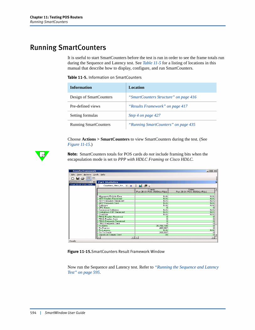
Chapter 11: Testing POS RoutersRunning SmartCounters
Running SmartCountersIt is useful to start SmartCounters before the test is run in order to see the frame totals run during the Sequence and Latency test. See Table 11-5 for a listing of locations in this manual that describe how to display, configure, and run SmartCounters.
Choose Actions > SmartCounters to view SmartCounters during the test. (See Figure 11-15.)
Note: SmartCounters totals for POS cards do not include framing bits when the encapsulation mode is set to PPP with HDLC Framing or Cisco HDLC.
Figure 11-15.SmartCounters Result Framework Window
Now run the Sequence and Latency test. Refer to “Running the Sequence and Latency Test” on page 595.
Table 11-5. Information on SmartCounters
Information Location
Design of SmartCounters “SmartCounters Structure” on page 416
Pre-defined views “Results Framework” on page 417
Setting formulas Step 4 on page 427
Running SmartCounters “Running SmartCounters” on page 435
594 | SmartWindow User Guide
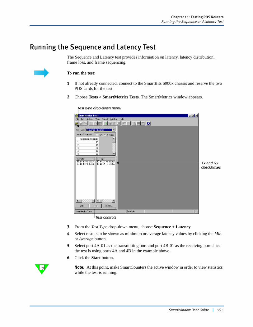
Chapter 11: Testing POS RoutersRunning the Sequence and Latency Test
Running the Sequence and Latency TestThe Sequence and Latency test provides information on latency, latency distribution, frame loss, and frame sequencing.
To run the test:
1 If not already connected, connect to the SmartBits 6000x chassis and reserve the twoPOS cards for the test.
2 Choose Tests > SmartMetrics Tests. The SmartMetrics window appears.
3 From the Test Type drop-down menu, choose Sequence + Latency.4 Select results to be shown as minimum or average latency values by clicking the Min.
or Average button.5 Select port 4A-01 as the transmitting port and port 4B-01 as the receiving port since
the test is using ports 4A and 4B in the example above.6 Click the Start button.
Note: At this point, make SmartCounters the active window in order to view statistics while the test is running.
Test type drop-down menu
Tx and Rxcheckboxes
Test controls
SmartWindow User Guide | 595
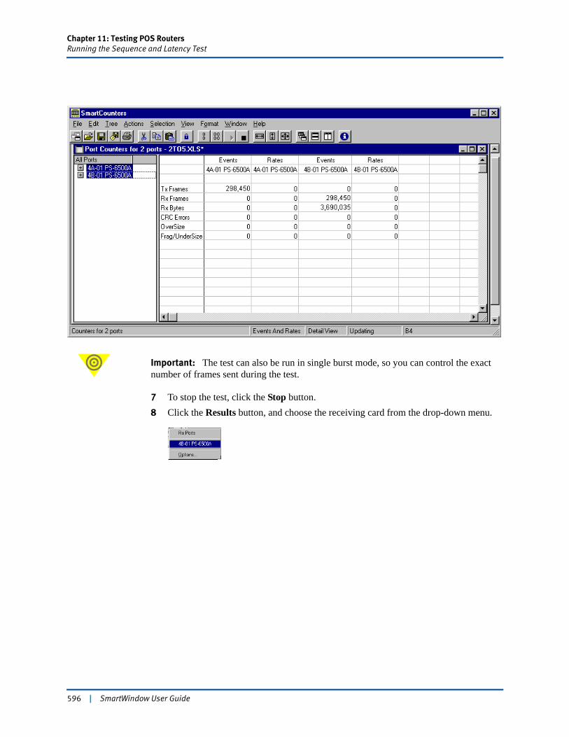
Chapter 11: Testing POS RoutersRunning the Sequence and Latency Test
Important: The test can also be run in single burst mode, so you can control the exact number of frames sent during the test.
7 To stop the test, click the Stop button.8 Click the Results button, and choose the receiving card from the drop-down menu.
596 | SmartWindow User Guide
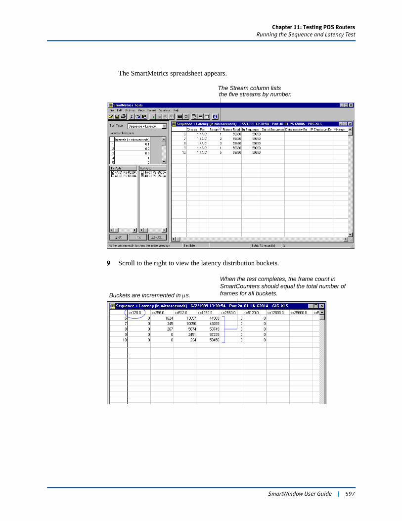
Chapter 11: Testing POS RoutersRunning the Sequence and Latency Test
The SmartMetrics spreadsheet appears.
9 Scroll to the right to view the latency distribution buckets.
The Stream column liststhe five streams by number.
Buckets are incremented in μs.
When the test completes, the frame count in SmartCounters should equal the total number of frames for all buckets.
SmartWindow User Guide | 597
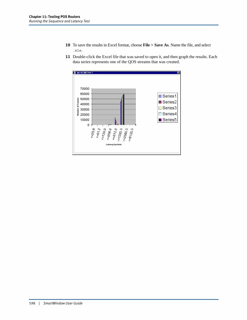
Chapter 11: Testing POS RoutersRunning the Sequence and Latency Test
10 To save the results in Excel format, choose File > Save As. Name the file, and select .xls.
11 Double-click the Excel file that was saved to open it, and then graph the results. Each data series represents one of the QOS streams that was created.
598 | SmartWindow User Guide
Chapter 12
Testing xDSL
The SmartBits system, ATM SmartCards, and SmartWindow provide a testing methodology which is highly effective in providing critical data to evaluate xDSL devices.
In order to deal with the increasing volume and bandwidth-intensive demand of multimedia, video, Internet, and e-mail services, xDSL offers several extremely cost-effective solutions over existing copper telephone lines.
In this chapter...
• xDSL Overview . . . . 600
• Test Methodology . . . . 601
• Connecting SmartBits to ADSL Network . . . . 604
• Configuring xDSL Tests . . . . 606
• Transit Delay Test . . . . 617
SmartWindow User Guide | 599
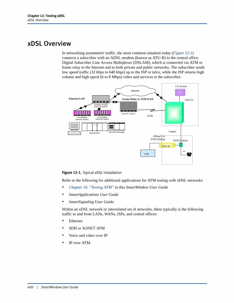
Chapter 12: Testing xDSLxDSL Overview
xDSL OverviewIn networking asymmetric traffic, the most common situation today (Figure 12-1) connects a subscriber with an ADSL modem (known as ATU-R) to the central office Digital Subscriber Line Access Multiplexer (DSLAM), which is connected via ATM or frame relay to the Internet and to both private and public networks. The subscriber sends low speed traffic (32 kbps to 640 kbps) up to the ISP or telco, while the ISP returns high volume and high speed (6 to 8 Mbps) video and services to the subscriber.
Figure 12-1. Typical xDSL Installation
Refer to the following for additional applications for ATM testing with xDSL networks:
• Chapter 10, “Testing ATM” in this SmartWindow User Guide
• SmartApplications User Guide
• SmartSignaling User Guide.
Within an xDSL network or interrelated set of networks, there typically is the following traffic to and from LANs, WANs, ISPs, and central offices:
• Ethernet
• SDH or SONET ATM
• Voice and video over IP
• IP over ATM.
Servers/StroageMainframe
Frame Relay or ATM WANEthernet LAN
ATM/FR Switch
10/100MbpsEthernet Switch
100Mbps/GigabitEthernet Switch
10/100MbpsEthernet Switch
Internet
Copper
10BaseT or ATM 25Mbps
ATU-R
CO Switch
ATMDSLAM
TELCO
POTS Splitter
CPE
600 | SmartWindow User Guide
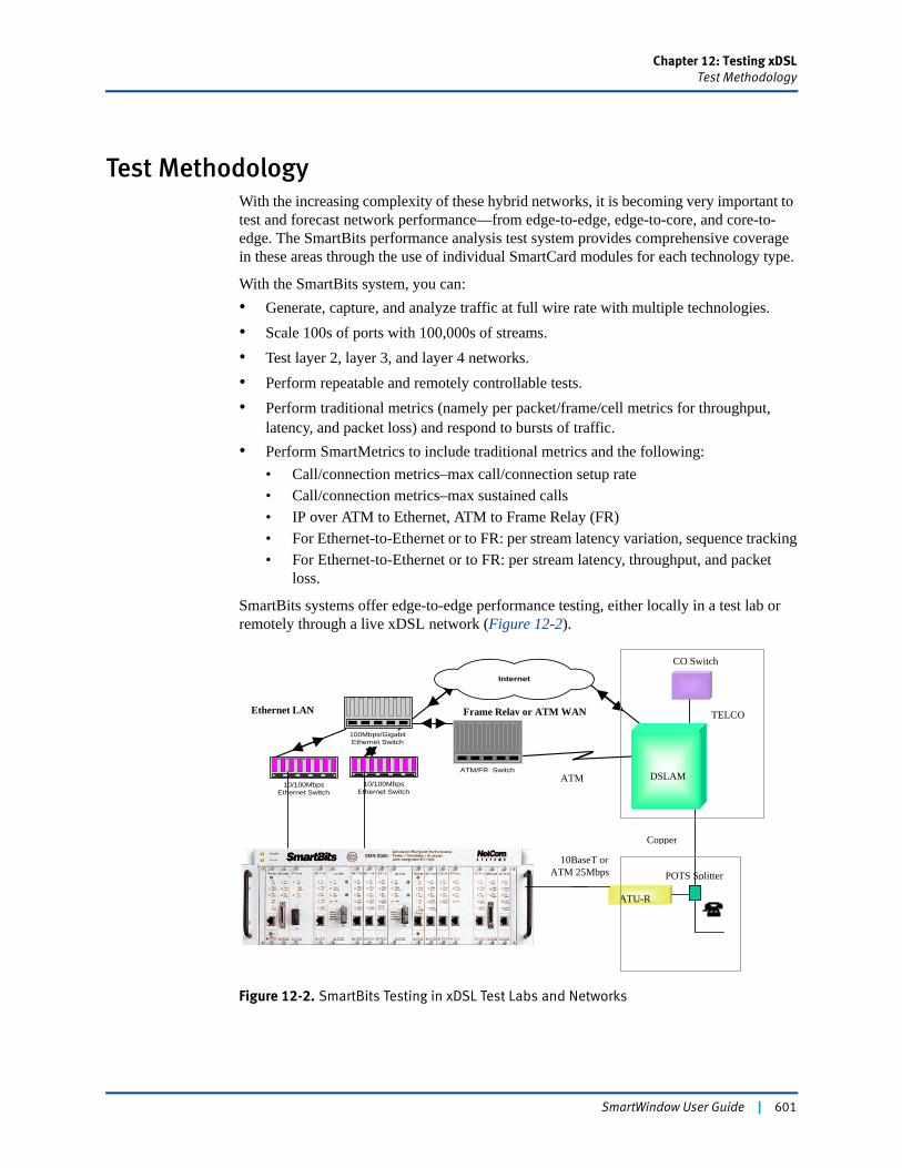
Chapter 12: Testing xDSLTest Methodology
Test MethodologyWith the increasing complexity of these hybrid networks, it is becoming very important to test and forecast network performance—from edge-to-edge, edge-to-core, and core-to-edge. The SmartBits performance analysis test system provides comprehensive coverage in these areas through the use of individual SmartCard modules for each technology type.
With the SmartBits system, you can:• Generate, capture, and analyze traffic at full wire rate with multiple technologies.• Scale 100s of ports with 100,000s of streams.• Test layer 2, layer 3, and layer 4 networks.• Perform repeatable and remotely controllable tests.• Perform traditional metrics (namely per packet/frame/cell metrics for throughput,
latency, and packet loss) and respond to bursts of traffic.• Perform SmartMetrics to include traditional metrics and the following:
• Call/connection metrics–max call/connection setup rate• Call/connection metrics–max sustained calls• IP over ATM to Ethernet, ATM to Frame Relay (FR)• For Ethernet-to-Ethernet or to FR: per stream latency variation, sequence tracking• For Ethernet-to-Ethernet or to FR: per stream latency, throughput, and packet
loss.
SmartBits systems offer edge-to-edge performance testing, either locally in a test lab or remotely through a live xDSL network (Figure 12-2).
Figure 12-2. SmartBits Testing in xDSL Test Labs and Networks
Frame Relay or ATM WANEthernet LAN
ATM/FR Switch
10/100MbpsEthernet Switch
100Mbps/GigabitEthernet Switch
10/100MbpsEthernet Switch
Internet
Copper
10BaseT or ATM 25Mbps
ATU-R
CO Switch
ATMDSLAM
TELCO
POTS Splitter
DSLAM
SmartWindow User Guide | 601
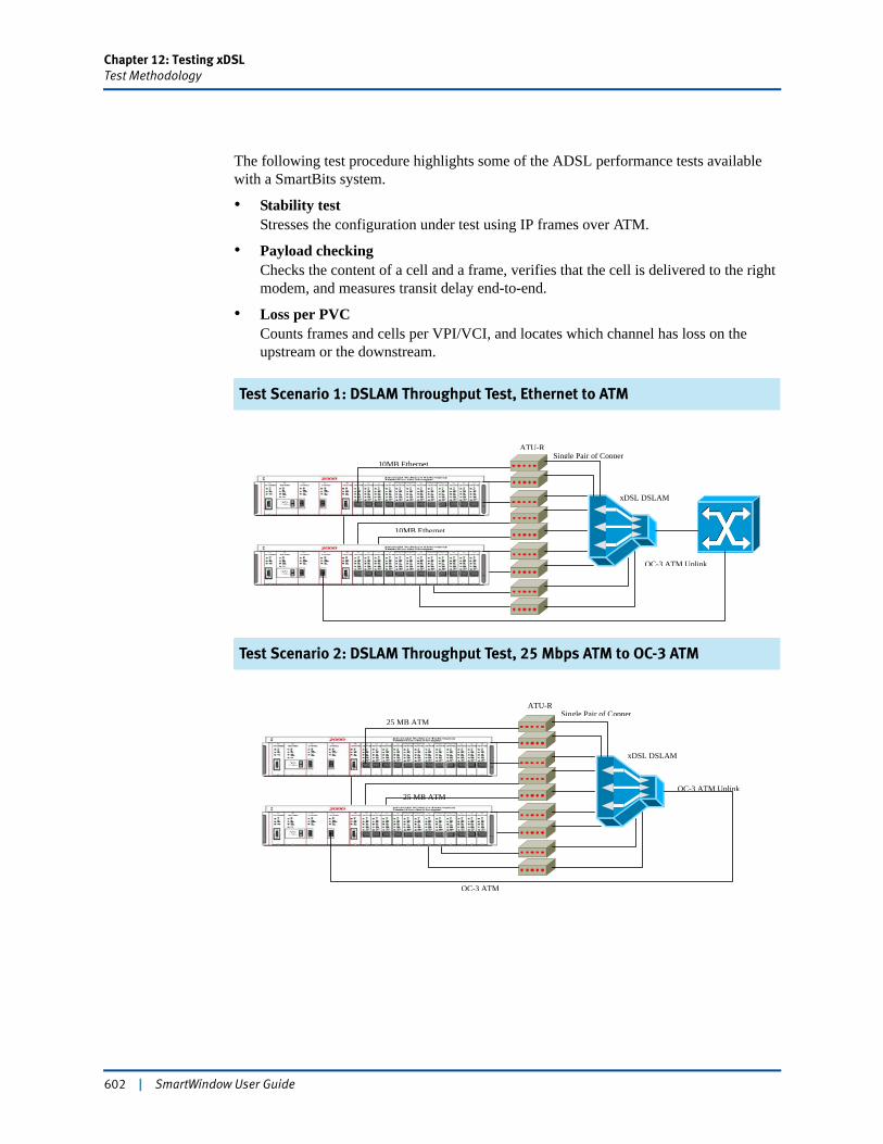
Chapter 12: Testing xDSLTest Methodology
The following test procedure highlights some of the ADSL performance tests available with a SmartBits system.
• Stability test Stresses the configuration under test using IP frames over ATM.
• Payload checking Checks the content of a cell and a frame, verifies that the cell is delivered to the right modem, and measures transit delay end-to-end.
• Loss per PVCCounts frames and cells per VPI/VCI, and locates which channel has loss on the upstream or the downstream.
Test Scenario 1: DSLAM Throughput Test, Ethernet to ATM
Test Scenario 2: DSLAM Throughput Test, 25 Mbps ATM to OC-3 ATM
Single Pair of Copper
xDSL DSLAM
OC-3 ATM Uplink
10MB Ethernet
10MB Ethernet
ATU-R
OC-3 ATM
Single Pair of Copper
xDSL DSLAM
OC-3 ATM Uplink25 MB ATM
25 MB ATM
ATU-R
602 | SmartWindow User Guide
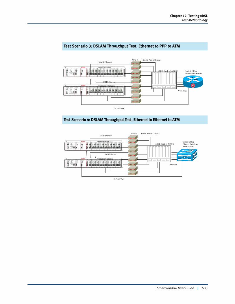
Chapter 12: Testing xDSLTest Methodology
Test Scenario 3: DSLAM Throughput Test, Ethernet to PPP to ATM
Test Scenario 4: DSLAM Throughput Test, Ethernet to Ethernet to ATM
Central OfficeAggregation Router
OC-3 ATM
Single Pair of Copper
xDSL Rack of ATU-C
V.35 Ports
10MB Ethernet
10MB EthernetATU-R
SiSi
Central OfficeEthernet Switch w/ATM Uplink
OC-3 ATM
Single Pair of Copper
xDSL Rack of ATU-C
Ethernet
10MB Ethernet
10MB EthernetATU-R
SmartWindow User Guide | 603
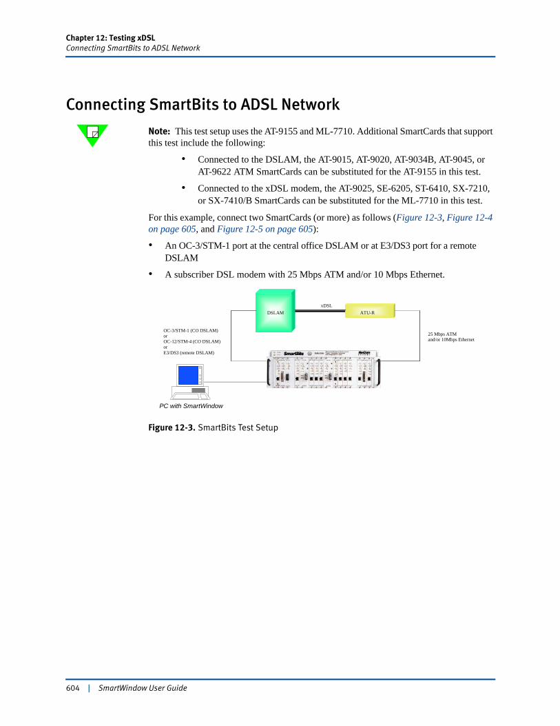
Chapter 12: Testing xDSLConnecting SmartBits to ADSL Network
Connecting SmartBits to ADSL Network
Note: This test setup uses the AT-9155 and ML-7710. Additional SmartCards that support this test include the following:
• Connected to the DSLAM, the AT-9015, AT-9020, AT-9034B, AT-9045, or AT-9622 ATM SmartCards can be substituted for the AT-9155 in this test.
• Connected to the xDSL modem, the AT-9025, SE-6205, ST-6410, SX-7210, or SX-7410/B SmartCards can be substituted for the ML-7710 in this test.
For this example, connect two SmartCards (or more) as follows (Figure 12-3, Figure 12-4 on page 605, and Figure 12-5 on page 605):
• An OC-3/STM-1 port at the central office DSLAM or at E3/DS3 port for a remote DSLAM
• A subscriber DSL modem with 25 Mbps ATM and/or 10 Mbps Ethernet.
Figure 12-3. SmartBits Test Setup
ATU-RDSLAMxDSL
25 Mbps ATMand/or 10Mbps Ethernet
OC-3/STM-1 (CO DSLAM)orOC-12/STM-4 (CO DSLAM)orE3/DS3 (remote DSLAM)
PC with SmartWindow
604 | SmartWindow User Guide
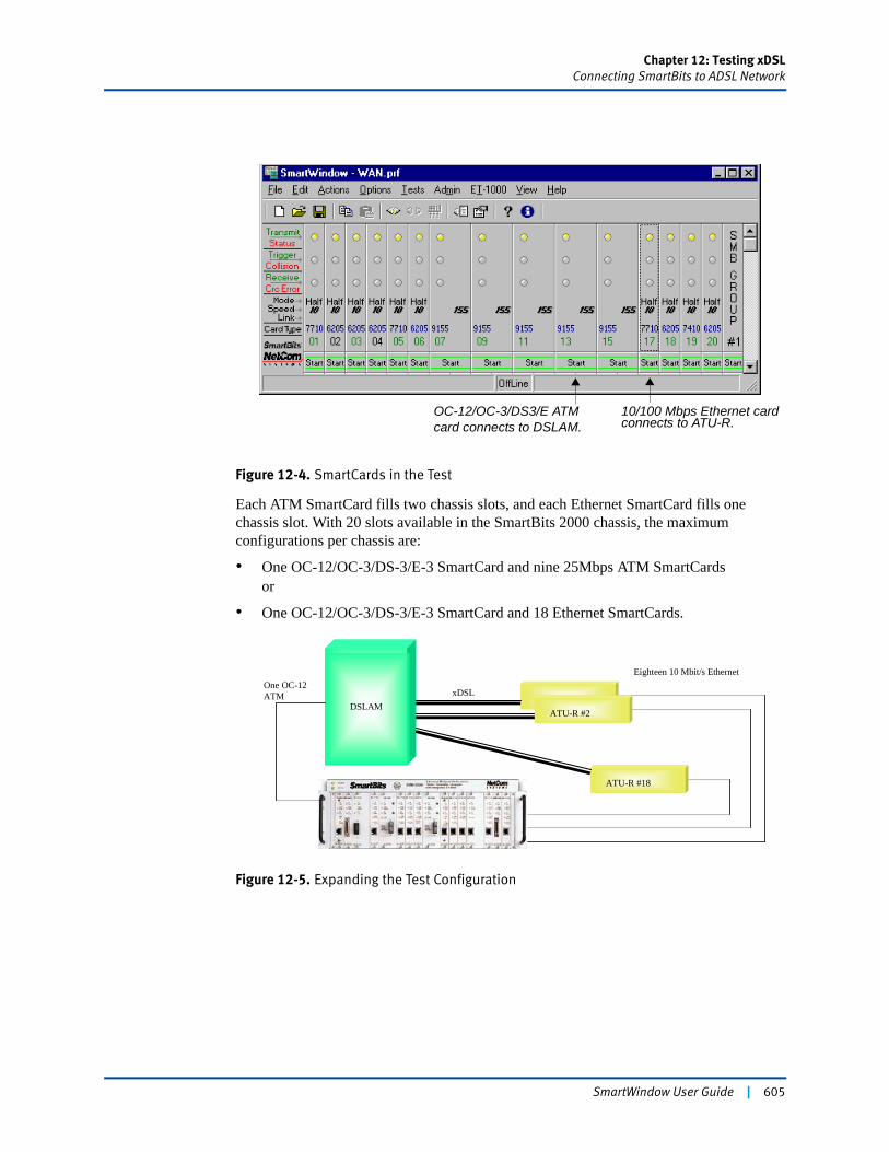
Chapter 12: Testing xDSLConnecting SmartBits to ADSL Network
Figure 12-4. SmartCards in the Test
Each ATM SmartCard fills two chassis slots, and each Ethernet SmartCard fills one chassis slot. With 20 slots available in the SmartBits 2000 chassis, the maximum configurations per chassis are:
• One OC-12/OC-3/DS-3/E-3 SmartCard and nine 25Mbps ATM SmartCardsor
• One OC-12/OC-3/DS-3/E-3 SmartCard and 18 Ethernet SmartCards.
Figure 12-5. Expanding the Test Configuration
OC-12/OC-3/DS3/E ATM card connects to DSLAM.
10/100 Mbps Ethernet card connects to ATU-R.
ATU-R #1 DSLAM
xDSL
ATU-R #2
ATU-R #18
Eighteen 10 Mbit/s EthernetOne OC-12ATM
SmartWindow User Guide | 605
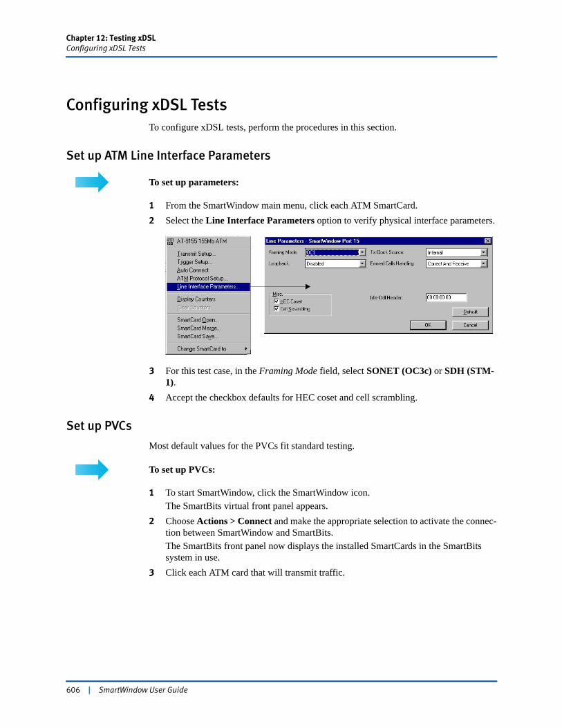
Chapter 12: Testing xDSLConfiguring xDSL Tests
Configuring xDSL TestsTo configure xDSL tests, perform the procedures in this section.
Set up ATM Line Interface Parameters
To set up parameters:
1 From the SmartWindow main menu, click each ATM SmartCard.2 Select the Line Interface Parameters option to verify physical interface parameters.
3 For this test case, in the Framing Mode field, select SONET (OC3c) or SDH (STM-1).
4 Accept the checkbox defaults for HEC coset and cell scrambling.
Set up PVCs
Most default values for the PVCs fit standard testing.
To set up PVCs:
1 To start SmartWindow, click the SmartWindow icon.The SmartBits virtual front panel appears.
2 Choose Actions > Connect and make the appropriate selection to activate the connec-tion between SmartWindow and SmartBits.The SmartBits front panel now displays the installed SmartCards in the SmartBits system in use.
3 Click each ATM card that will transmit traffic.
606 | SmartWindow User Guide
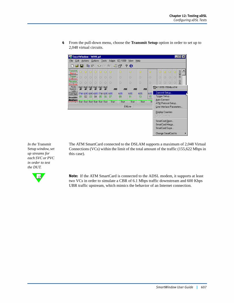
Chapter 12: Testing xDSLConfiguring xDSL Tests
4 From the pull-down menu, choose the Transmit Setup option in order to set up to 2,048 virtual circuits.
In the Transmit Setup window, set up streams for each SVC or PVC in order to test the DUT.
The ATM SmartCard connected to the DSLAM supports a maximum of 2,048 Virtual Connections (VCs) within the limit of the total amount of the traffic (155,622 Mbps in this case).
Note: If the ATM SmartCard is connected to the ADSL modem, it supports at least two VCs in order to simulate a CBR of 6.1 Mbps traffic downstream and 600 Kbps UBR traffic upstream, which mimics the behavior of an Internet connection.
SmartWindow User Guide | 607
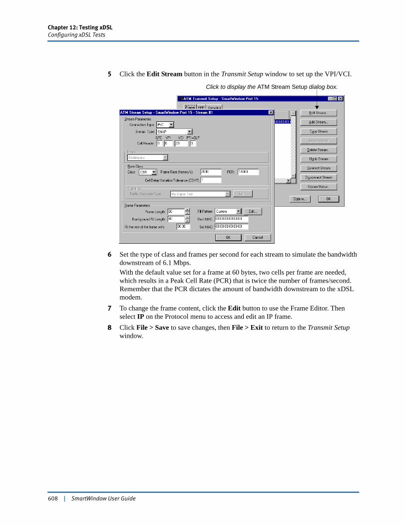
Chapter 12: Testing xDSLConfiguring xDSL Tests
5 Click the Edit Stream button in the Transmit Setup window to set up the VPI/VCI.
6 Set the type of class and frames per second for each stream to simulate the bandwidth downstream of 6.1 Mbps.With the default value set for a frame at 60 bytes, two cells per frame are needed, which results in a Peak Cell Rate (PCR) that is twice the number of frames/second. Remember that the PCR dictates the amount of bandwidth downstream to the xDSL modem.
7 To change the frame content, click the Edit button to use the Frame Editor. Then select IP on the Protocol menu to access and edit an IP frame.
8 Click File > Save to save changes, then File > Exit to return to the Transmit Setup window.
Click to display the ATM Stream Setup dialog box.
608 | SmartWindow User Guide
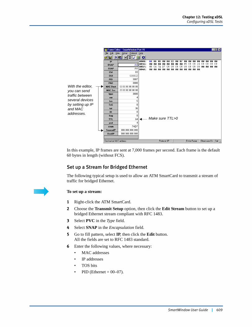
Chapter 12: Testing xDSLConfiguring xDSL Tests
In this example, IP frames are sent at 7,000 frames per second. Each frame is the default 60 bytes in length (without FCS).
Set up a Stream for Bridged Ethernet
The following typical setup is used to allow an ATM SmartCard to transmit a stream of traffic for bridged Ethernet.
To set up a stream:
1 Right-click the ATM SmartCard. 2 Choose the Transmit Setup option, then click the Edit Stream button to set up a
bridged Ethernet stream compliant with RFC 1483.3 Select PVC in the Type field.4 Select SNAP in the Encapsulation field.5 Go to fill pattern, select IP, then click the Edit button.
All the fields are set to RFC 1483 standard.6 Enter the following values, where necessary:
• MAC addresses• IP addresses• TOS bits• PID (Ethernet = 00–07).
With the editor, you can send traffic between several devices by setting up IP and MAC addresses.
Make sure TTL>0
SmartWindow User Guide | 609
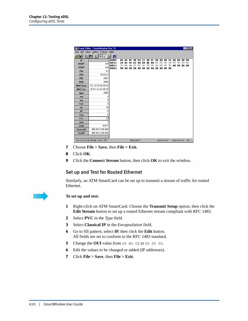
Chapter 12: Testing xDSLConfiguring xDSL Tests
7 Choose File > Save, then File > Exit.8 Click OK.9 Click the Connect Stream button, then click OK to exit the window.
Set up and Test for Routed Ethernet
Similarly, an ATM SmartCard can be set up to transmit a stream of traffic for routed Ethernet.
To set up and test:
1 Right-click on ATM SmartCard. Choose the Transmit Setup option, then click the Edit Stream button to set up a routed Ethernet stream compliant with RFC 1483.
2 Select PVC in the Type field.3 Select Classical IP in the Encapsulation field.4 Go to fill pattern, select IP, then click the Edit button.
All fields are set to conform to the RFC 1483 standard. 5 Change the OUI value from 00 80 C2 to 00 00 00.6 Edit the values to be changed or added (IP addresses).7 Click File > Save, then File > Exit.
610 | SmartWindow User Guide
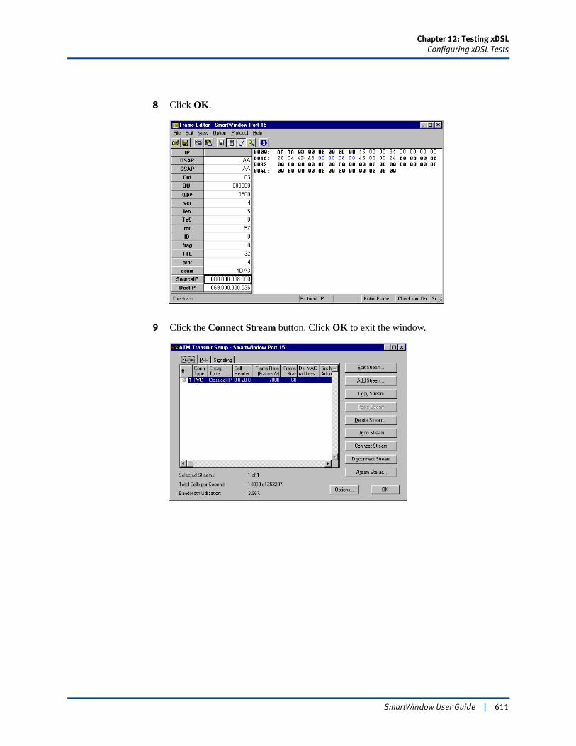
Chapter 12: Testing xDSLConfiguring xDSL Tests
8 Click OK.
9 Click the Connect Stream button. Click OK to exit the window.
SmartWindow User Guide | 611
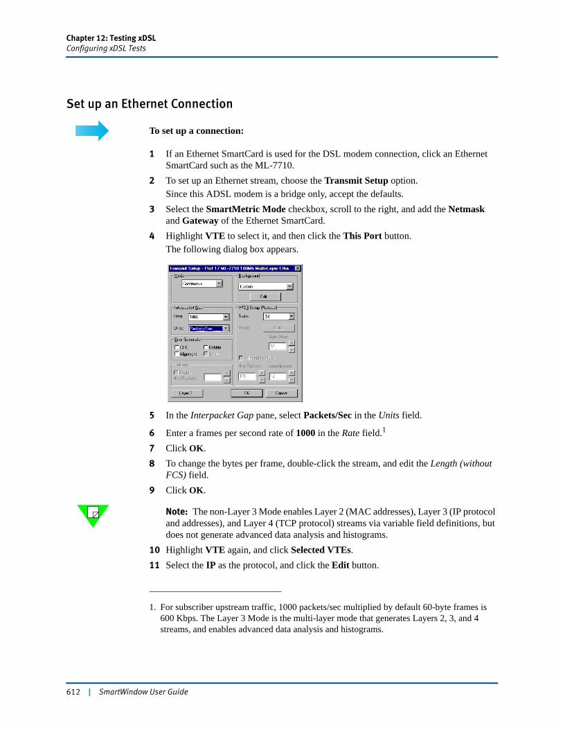
Chapter 12: Testing xDSLConfiguring xDSL Tests
Set up an Ethernet Connection
To set up a connection:
1 If an Ethernet SmartCard is used for the DSL modem connection, click an Ethernet SmartCard such as the ML-7710.
2 To set up an Ethernet stream, choose the Transmit Setup option.Since this ADSL modem is a bridge only, accept the defaults.
3 Select the SmartMetric Mode checkbox, scroll to the right, and add the Netmask and Gateway of the Ethernet SmartCard.
4 Highlight VTE to select it, and then click the This Port button.The following dialog box appears.
5 In the Interpacket Gap pane, select Packets/Sec in the Units field.
6 Enter a frames per second rate of 1000 in the Rate field.1
7 Click OK.8 To change the bytes per frame, double-click the stream, and edit the Length (without
FCS) field. 9 Click OK.
Note: The non-Layer 3 Mode enables Layer 2 (MAC addresses), Layer 3 (IP protocol and addresses), and Layer 4 (TCP protocol) streams via variable field definitions, but does not generate advanced data analysis and histograms.
10 Highlight VTE again, and click Selected VTEs.11 Select the IP as the protocol, and click the Edit button.
1. For subscriber upstream traffic, 1000 packets/sec multiplied by default 60-byte frames is 600 Kbps. The Layer 3 Mode is the multi-layer mode that generates Layers 2, 3, and 4 streams, and enables advanced data analysis and histograms.
612 | SmartWindow User Guide
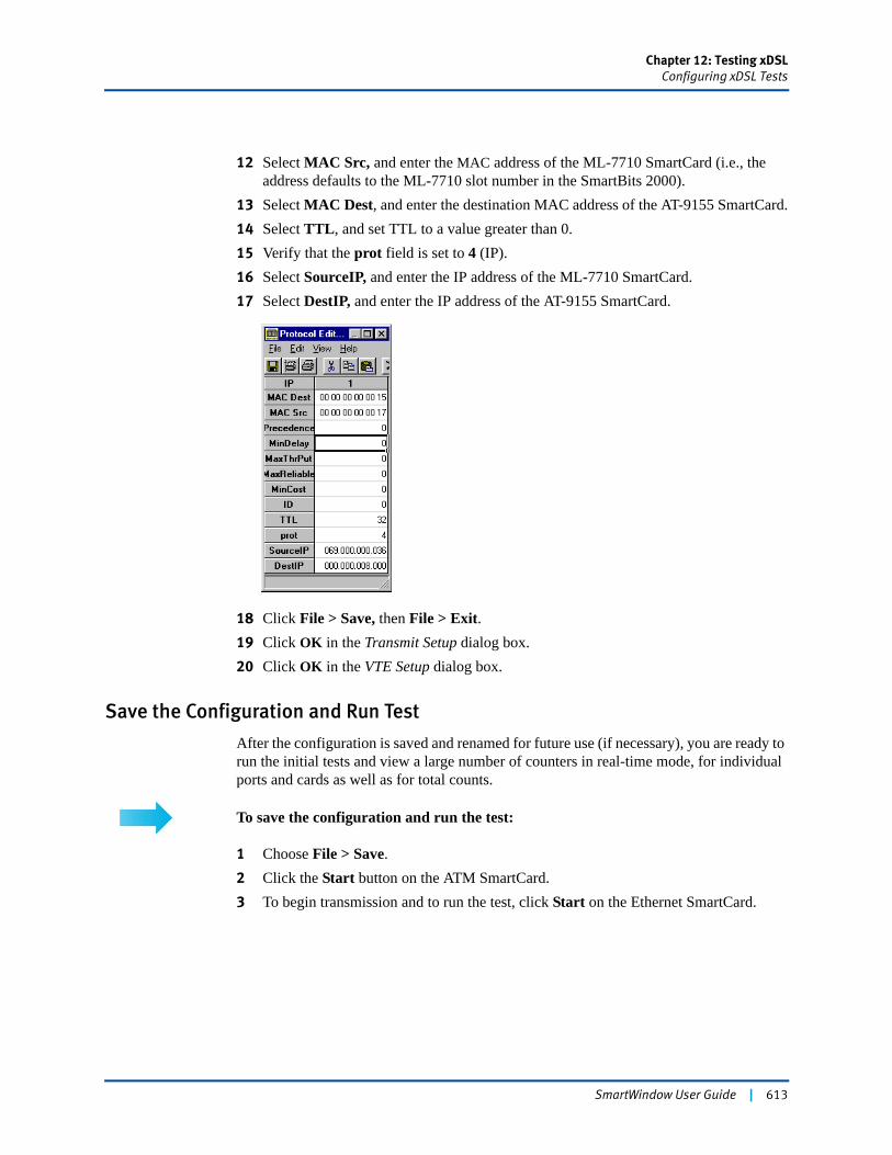
Chapter 12: Testing xDSLConfiguring xDSL Tests
12 Select MAC Src, and enter the MAC address of the ML-7710 SmartCard (i.e., the address defaults to the ML-7710 slot number in the SmartBits 2000).
13 Select MAC Dest, and enter the destination MAC address of the AT-9155 SmartCard.14 Select TTL, and set TTL to a value greater than 0.15 Verify that the prot field is set to 4 (IP).16 Select SourceIP, and enter the IP address of the ML-7710 SmartCard.17 Select DestIP, and enter the IP address of the AT-9155 SmartCard.
18 Click File > Save, then File > Exit.19 Click OK in the Transmit Setup dialog box.20 Click OK in the VTE Setup dialog box.
Save the Configuration and Run Test
After the configuration is saved and renamed for future use (if necessary), you are ready to run the initial tests and view a large number of counters in real-time mode, for individual ports and cards as well as for total counts.
To save the configuration and run the test:
1 Choose File > Save.2 Click the Start button on the ATM SmartCard.3 To begin transmission and to run the test, click Start on the Ethernet SmartCard.
SmartWindow User Guide | 613
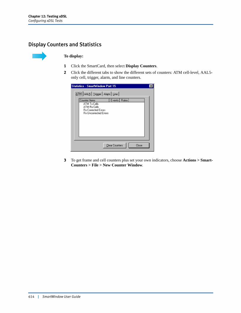
Chapter 12: Testing xDSLConfiguring xDSL Tests
Display Counters and Statistics
To display:
1 Click the SmartCard, then select Display Counters.2 Click the different tabs to show the different sets of counters: ATM cell-level, AAL5-
only cell, trigger, alarm, and line counters.
3 To get frame and cell counters plus set your own indicators, choose Actions > Smart-Counters > File > New Counter Window.
614 | SmartWindow User Guide
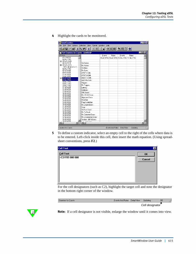
Chapter 12: Testing xDSLConfiguring xDSL Tests
4 Highlight the cards to be monitored.
5 To define a custom indicator, select an empty cell to the right of the cells where data is to be entered. Left-click inside this cell, then insert the math equation. (Using spread-sheet conventions, press F2.)
For the cell designators (such as C2), highlight the target cell and note the designator in the bottom right corner of the window.
Note: If a cell designator is not visible, enlarge the window until it comes into view.
Cell designator
SmartWindow User Guide | 615

Chapter 12: Testing xDSLConfiguring xDSL Tests
6 To view statistics per VC or stream, click the + sign to open SmartCounters per stream statistics.
Click buttons to hide/display per stream statistics.
616 | SmartWindow User Guide
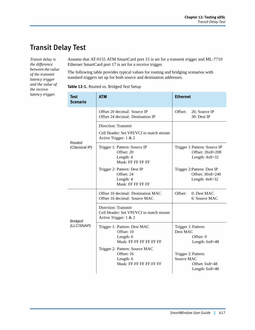
Chapter 12: Testing xDSLTransit Delay Test
Transit Delay TestTransit delay is the difference between the value of the transmit latency trigger and the value of the receive latency trigger.
Assume that AT-9155 ATM SmartCard port 15 is set for a transmit trigger and ML-7710 Ethernet SmartCard port 17 is set for a receive trigger.
The following table provides typical values for routing and bridging scenarios with standard triggers set up for both source and destination addresses.
Table 12-1. Routed vs. Bridged Test Setup
Test Scenario
ATM Ethernet
Routed(Classical IP)
Offset 20 decimal: Source IPOffset 24 decimal: Destination IP
Offset: 26: Source IP30: Dest IP
Direction: Transmit
Cell Header: Set VPI/VCI to match streamActive Trigger: 1 & 2
Trigger 1: Pattern: Source IP Offset: 20
Length: 4Mask: FF FF FF FF
Trigger 2: Pattern: Dest IPOffset: 24Length: 4Mask: FF FF FF FF
Trigger 1:Pattern: Source IPOffset: 26x8=208Length: 4x8=32
Trigger 2:Pattern: Dest IPOffset: 30x8=240Length: 4x8=32
Bridged(LLC/SNAP)
Offset 10 decimal: Destination MACOffset 16 decimal: Source MAC
Offset: 0: Dest MAC6: Source MAC
Direction: TransmitCell Header: Set VPI/VCI to match streamActive Trigger: 1 & 2
Trigger 1: Pattern: Dest MACOffset: 10Length: 6Mask: FF FF FF FF FF FF
Trigger 2: Pattern: Source MACOffset: 16Length: 6Mask: FF FF FF FF FF FF
Trigger 1: Pattern:Dest MAC Offset: 0 Length: 6x8=48
Trigger 2: Pattern:Source MAC Offset: 6x8=48
Length: 6x8=48
SmartWindow User Guide | 617
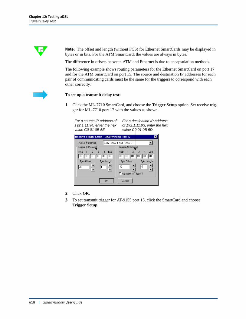
Chapter 12: Testing xDSLTransit Delay Test
Note: The offset and length (without FCS) for Ethernet SmartCards may be displayed in bytes or in bits. For the ATM SmartCard, the values are always in bytes.
The difference in offsets between ATM and Ethernet is due to encapsulation methods.
The following example shows routing parameters for the Ethernet SmartCard on port 17 and for the ATM SmartCard on port 15. The source and destination IP addresses for each pair of communicating cards must be the same for the triggers to correspond with each other correctly.
To set up a transmit delay test:
1 Click the ML-7710 SmartCard, and choose the Trigger Setup option. Set receive trig-ger for ML-7710 port 17 with the values as shown.
2 Click OK.3 To set transmit trigger for AT-9155 port 15, click the SmartCard and choose
Trigger Setup.
For a source IP address of 192.1.11.94, enter the hex value C0 01 0B 5E.
For a destination IP address of 192.1.11.93, enter the hex value C0 01 0B 5D.
618 | SmartWindow User Guide
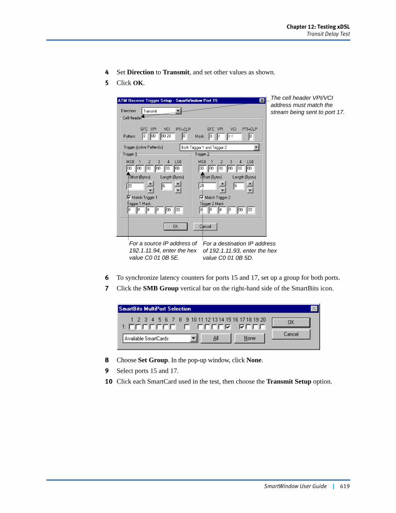
Chapter 12: Testing xDSLTransit Delay Test
4 Set Direction to Transmit, and set other values as shown. 5 Click OK.
6 To synchronize latency counters for ports 15 and 17, set up a group for both ports.7 Click the SMB Group vertical bar on the right-hand side of the SmartBits icon.
8 Choose Set Group. In the pop-up window, click None. 9 Select ports 15 and 17.10 Click each SmartCard used in the test, then choose the Transmit Setup option.
For a destination IP address of 192.1.11.93, enter the hex value C0 01 0B 5D.
For a source IP address of 192.1.11.94, enter the hex value C0 01 0B 5E.
The cell header VPI/VCI address must match the stream being sent to port 17.
SmartWindow User Guide | 619
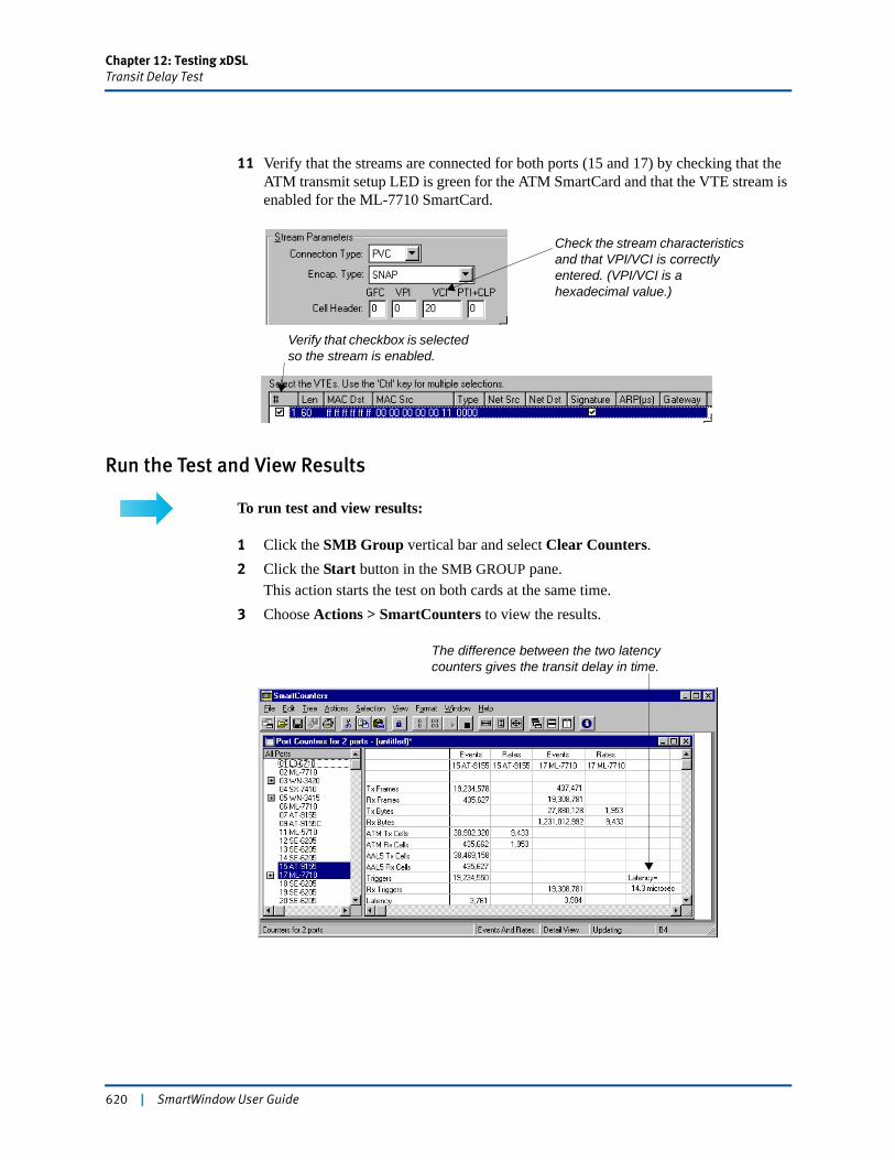
Chapter 12: Testing xDSLTransit Delay Test
11 Verify that the streams are connected for both ports (15 and 17) by checking that the ATM transmit setup LED is green for the ATM SmartCard and that the VTE stream is enabled for the ML-7710 SmartCard.
Run the Test and View Results
To run test and view results:
1 Click the SMB Group vertical bar and select Clear Counters.2 Click the Start button in the SMB GROUP pane.
This action starts the test on both cards at the same time.3 Choose Actions > SmartCounters to view the results.
Check the stream characteristics and that VPI/VCI is correctly entered. (VPI/VCI is a hexadecimal value.)
Verify that checkbox is selected so the stream is enabled.
The difference between the two latency counters gives the transit delay in time.
620 | SmartWindow User Guide
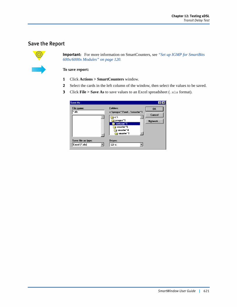
Chapter 12: Testing xDSLTransit Delay Test
Save the Report
Important: For more information on SmartCounters, see “Set up IGMP for SmartBits 600x/6000x Modules” on page 120.
To save report:
1 Click Actions > SmartCounters window.2 Select the cards in the left column of the window, then select the values to be saved.3 Click File > Save As to save values to an Excel spreadsheet (.xls format).
SmartWindow User Guide | 621

622 | SmartWindow User Guide

Chapter 13
Testing Storage Area Networks
The FBC-3601A and FBC-3602A Fibre Channel modules provide an outstanding tool to assess the performance of fibre channel switches, hubs, and fabrics.
Use SmartWindow with these modules to perform tests for throughput, frame loss, latency, and sequence tracking on systems ranging from a single Device Under Test (DUT) to a large complex SAN network (fabric). You can set up multiple flows of FC frames to simulate traffic in a SAN network plus measure latency and frame loss.
In this chapter...
• About Fibre Channel and SANs . . . . 624
• Terminology . . . . 625
• Test Using the FBC-3601A Module . . . . 633
• Send Traffic and View Counters . . . . 660
• Running SmartMetrics Tests . . . . 664
• Data Capture . . . . 665
SmartWindow User Guide | 623
Chapter 13: Testing Storage Area NetworksAbout Fibre Channel and SANs
About Fibre Channel and SANsFibre channel defines a method of data transport with the primary goal of transferring data at the fastest possible rate using any current media. Because of its speed, capacity, and flexibility, fibre channel has been widely adopted for use in storage area networks, which require the rapid transfer of large quantities of data between servers and storage systems.
Fibre channel may be used with both fiber and non-fiber serial media (such as copper coaxial cable or twisted pair). It applies to both channel-based communications (peripheral-to-host) and network communications among many host interfaces.
Supported Standards
Operation of the FBC-3601A/FBC-6302A modules in SmartWindow conforms to the following ANSI and other standards for fibre channel.
Table 13-1. ANSI Standards Support
Reference Title
RFC 1242 Benchmarking Terminology for Network Interconnection Devices
RFC 2544 Benchmarking Methodology for Network Interconnect Devices
GBIC Rev. 5.2 –
ANSI X3.230-1994, FC-PH Fibre Channel - Physical and Signaling Interface, Rev. 4.3
ANSI X3.297-1996, FC-PH 2 Fibre Channel - Physical and Signaling Interface, Rev 7.4
ANSI X3.303-1996, FC-PH 3 Fibre Channel - Physical and Signaling Interface, Rev 9.4
ANSI X3.272-1996, FC-AL Fibre Channel - Arbitrated Loop, Rev 4.5
ANSI X3.332-1999, FC-AL 2 Fibre Channel - Arbitrated Loop, Rev 7.0
ANSI X3.289-1996, FC-FG Fibre Channel - Fabric Generic Requirements, Rev 3.5
NCITS TR-20-1998, FC-FLA Fibre Channel - Fabric Loop Attachment, Rev 2.7
NCITS 321-200x, FC-SW Fibre Channel - Switch Fabric, Rev 4.0
NCITS TR-19-1998, PLDA Fibre Channel - Private Loop Direct Attach, Rev 2.1
624 | SmartWindow User Guide
Chapter 13: Testing Storage Area NetworksTerminology
TerminologyThis section describes the terminology introduced in this chapter, as well as selected related terms used in telecommunications technology and standards.
Arbitrated Loop
A fibre channel topology in which two or more ports can be interconnected, but only two at a time can communicate. The loop supports up to 126 devices and one fabric attachment on one loop. Each device in the loop must arbitrate for access and use of the shared medium.
Arbitrated Loop Physical Address (ALPA)
The value that identifies a device in an arbitrated loop. This value is always the last 8 bits of the 24-bit address field.
Arbitration
The process that controls orderly access to a shared-loop technology.
Backbone
The test traffic pattern in SmartWindow in which traffic can be configured from one to many ports or from many to one port. Traffic can be uni-directional or bi-directional.
Binary Test Mode
The search mode used to determine the maximum transmission rate of the DUT or SUT when no frame loss or acceptable frame loss occurs. It is also known as scaled search, in which the search determines a rate between the last failed rate and the last successful rate.
Buffer-to-Buffer (BB) Credit
The fibre channel flow control system that determines how many frames can be sent to a recipient. A credit represents the ability of a device to accept an additional frame. If no credits are issued by a recipient to a sender, the sender cannot send to that recipient.
Channel
In fibre channel, the medium for high-speed transfer of information between devices.
Class of Service (CoS)
The fibre channel term for five levels (i.e., classes) of services provided in the areas of delivery guarantees, bandwidth, and connectivity between communicating devices in a fabric network. SmartWindow supports classes 2 and 3.
Class 2
A connectionless Class of Service (CoS) that allows streams of frames to be sent to different destinations quickly and requires acknowledgment of frame delivery. It is generally used in applications requiring a high degree of data integrity at the transport level.
SmartWindow User Guide | 625

Chapter 13: Testing Storage Area NetworksTerminology
Class 3
A connectionless CoS that does not require acknowledgment of frame delivery. Class 3 provides higher performance with less overhead, but can be less reliable since under highly congested conditions, it may discard frames.
Combo Test Mode
A test mode that combines the step and binary search operations. The mode begins in step test mode, stepping up the rate until the test fails. It then performs binary searches to determine a rate between the last failed rate and the last successful rate.
Cut-through Logic
A switching technique that allows a routing decision to be made a soon as the destination address of a frame is received.
Cyclic Redundancy Check (CRC)
A method of checking for errors in transmitted data, it is used to protect blocks of data called frames. Using this technique, the transmitter appends an extra n-bit sequence, called Frame Check Sequence (FCS), to every frame. The FCS holds redundant information about the frame that helps the transmitter detect errors in the frame.
Dense Wave Division Multiplexing (DWDM)
In data transmission systems, Wave Division Multiplexing (WDM) is a way to greatly increase the capacity of a single optical fiber by simultaneously transmitting at more than one wavelength of light (e.g., up to four wavelengths for WDM). DWDM is the higher capacity version of WDM and supports from 8 to 40 wavelengths.
Destination WWN
The World-Wide Name (WWN) that identifies the port that will receive the frame. (See also Source WWN and World Wide Name.)
Device
A single unit on the SCSI bus, identifiable by a unique SCSI address. A SCSI device can act as an initiator or as a target.
Discovery
In a fabric network, the process of identifying other devices in the network. (See also Name Server and Loop Initialization.)
Duration
A test setup field used to specify the length of a test. The test can be measured in seconds that the test is to run at each load interval, or in number of frames sent per test iteration.
Device Under Test (DUT)
The device being tested.
626 | SmartWindow User Guide
Chapter 13: Testing Storage Area NetworksTerminology
E_Port
An expansion port on a switch that is used to connect to another E_port on a different switch. This type of connection is used to connect several devices in order to create a large fabric.
Extended Link Services (ELS)
Additional control functions added to fibre channel from time to time by ANSI, such as PLOGI and FLOGI.
Exchange
A mechanism for identifying and managing an operation between two ports.
Exchange ID
The 16-bit identifier assigned to a specific operation.
Fabric
One or more fibre channel switch(es) in a network configuration in which each port in a node (device) is attached to the fabric through a link that consists of a pair of fibers. (See also Link.)
Failover
When a network component (such as a disk or server) fails, this is the automatic process that switches from the failed component to its redundant backup. The process is transparent to the user. In SmartFabric, the failover test is used to determine downtime in a network with failover capability.
Fiber
A generic term that describes the serial media types supported by fibre channel, such as coaxial cable, optical, or twisted pair. (See also Link.)
Fibre Channel
The set of ANSI standards that describe the serial gigabit transport protocol that supports both channel and network users.
FLOGI
Fabric Login. The process in which a port establishes all network operating parameters between two participants. (See also Fabric and Port Login.)
Flow
One or more frames sent from one or more sources to one or more destinations that are tracked as a single entity. (See also SmartFlow and Group.)
F_Port
Fabric Port. A physical interface within a fabric (switch) that attaches to an N-port (node port) through a point-to-point connection. (See also N_Port.)
FL_Port
Fabric Loop Port. An F_port containing arbitrated loop functions.
SmartWindow User Guide | 627

Chapter 13: Testing Storage Area NetworksTerminology
Frame
The basic (indivisible) fibre channel unit of data transmission.
Frame Check Sequence
See “Cyclic Redundancy Check (CRC)” on page 626.
Frame Loss
In SmartBits applications, this is a test that measures the ability of a device to deliver variably-sized frames at different traffic loads.
Fully-meshed
The test traffic pattern in SmartWindow in which every port transmits to every port.
Gigabit
For fibre channel, 1,062,500,000 bits per second.
Gigabit Interface Converter (GBIC)
A type of port connector. In fibre channel, a removable transceiver module.
Group
A number of flows that have been logically combined for purposes of analyzing test results. Any flow can be included in a group, and the same flow can be included in more than one group.
Initiator
A server or workstation in a fibre channel network that starts transactions to disk or tape. (See also Target.)
Iteration
The smallest unit or phase of a test that occurs within the trials of a test. Iterations allow you to see how the performance of the DUT is affected by changes in a particular test parameter. A single trial can have many iterations, depending on the test configuration. (See also Trial.)
Jitter
The variation in latency between frames in a flow. This is also known as latency standard deviation.
LAN
Local Area Network. A high-speed network of computers and devices typically limited to a relatively small area (such as a single building or campus). It is connected by a link that allows any device (node) on the network to interact with any other device on the network. Typically, it is limited to a small area, such as a floor in a building, a building, or a campus.
628 | SmartWindow User Guide
Chapter 13: Testing Storage Area NetworksTerminology
Latency
The time interval between the transmission and reception of a frame. In SmartBits applications, this is a test that measures the ability of a device to manage prioritized traffic at different loads.
Latency Distribution
In SmartBits applications, this is a test that measures the latency across a user-defined distribution of eight possible time buckets. Compared to the Latency test, this test provides a more detailed view of latency behavior at the DUT load tolerance limits.
Latency Snapshot
In SmartBits applications, this is a test that provides the most magnified view at the DUT load tolerance limits.
Learning Phase
The initialization process that begins once a test is started. It consists of the following phases: establish hardware connections and configuration information, initialize ports, perform link initialization and device discovery procedures, and run the test.
Link
In fibre channel, the communications channel between two nodes or ports that carry information in to and out of a port.
Load
The rate at which a port transmits traffic as a percentage of full wire rate.
Loop
See Arbitrated Loop.
Loop Initialization
Part of the initialization process in a fibre channel arbitrated loop that assigns the Arbitrated Loop Physical Addresses (ALPAs) to new devices in the loop. The process also provides notification of changes in the topology and recovery from loop failure. (See also Arbitrated Loop and Arbitrated Loop Physical Address.)
Name Server Table
A table of known WWNs and their associated address IDs.
Node
A device that has at least one N_port or one NL_port.
N_Port
Node Port. A physical interface within a node that may attach to an F_port or directly to another N_port through a point-to-point connection. (See also F_Port.)
NL_Port
Node Loop Port. The end node ports in an arbitrated loop.
SmartWindow User Guide | 629

Chapter 13: Testing Storage Area NetworksTerminology
OX_ID
Originator exchange ID. The 16-bit identifier assigned by the exchange originator to a specific operation.
Pairs
The test traffic pattern in SmartWindow that consists of pairs of ports that transmit only within each pair. Traffic can be uni- or bi-directional.
PLOGI
Port Login. The process in which a port sends its port-to-port operating parameters to every port in the network that it needs to communicate with.
Point-to-Point (PT2PT)
A dedicated fibre channel connection (link) between two devices. (See also Topology.)
Port
Any type of physical device that connects a node to a network.
Port Name
See World Wide Name.
Private Discovery
A task in the learning phase that performs the port login process (PLOGI) for all physical addresses on the loop. (See also Port Login and Learning Phase.)
Private Loop
A free-standing arbitrated loop with no fabric attachments. (See also Arbitrated Loop and Public Loop.)
Public Discovery
A task in the learning phase that performs a name server query for remote public devices. (See also Name Server Registration and Learning Phase.)
Public Loop
An arbitrated loop attached to a (SAN) fabric switch. (See also Arbitrated Loop and Private Loop.)
R_RDY
An ordered set that is used to control the transmission of frames on a link. It indicates that a receiver has emptied a receiver buffer and is ready to receive another frame.
Request for Comments (RFC)
The document series used as the primary source for communicating information about the Internet.
Rx
The abbreviation for a SmartBits module receiving (destination) port.
630 | SmartWindow User Guide

Chapter 13: Testing Storage Area NetworksTerminology
SAN
See Storage Area Network.
Small Computer System Interface (SCSI)
A high-speed interface used to connect computers to SCSI peripheral devices.
SEQ_CNT
Identifies the location of individual frames within a sequence of multiple frames.
SEQ_ID
Sequence ID. The parameter in the 24-byte fibre channel message header that identifies a sequence of multiple frames.
SmartFlow
The term used in SmartFabric for a trackable entity that contains one or more flows. Each SmartFlow contains a series of frames that travel from one or more sources to one or more destinations and provides the ability to vary addresses and/or port numbers. Each variation comprises one flow. (See also Flow and Group.)
SmartMetrics
The Spirent Communications performance analysis system that measures how well devices and networks optimize, prioritize, and segment traffic at all network levels.
Source WWN
The world-wide name that identifies the sender of the frame.
Step Test Mode
The search mode used to determine the DUT or SUT maximum transmission rate with no frame loss or acceptable frame loss. This mode increases the rate by the same percentage (step) added to the current rate.
Storage Area Network (SAN)
A collection of servers, clients, switches, and routers that carry data traffic using SCSI and fibre channel (usually SCSI over fibre channel).
Switch
A device that provides full bandwidth per port and high-speed routing of data through logic level addressing. (See also Topology.)
System Under Test (SUT)
Multiple DUTs that are configured as a network or a system.
Target
A disk array or tape subsystem in a fibre channel network.
Throughput
In Smartbits applications, this is a test that measures the rate at which frames from flows and groups sent through a device can be sent without frame loss. In the
SmartWindow User Guide | 631

Chapter 13: Testing Storage Area NetworksTerminology
Throughput test, it measures the maximum transmission rate at which the DUT can forward traffic when not restricted by flow control.
Topology
The logical or physical arrangement of devices in a network configuration. Topology also refers to a specific way of connecting the components, such as point-to-point or arbitrated loop. (See also Point-to-Point Arbitrated Loop and Fabric.)
Traffic Distribution
The pattern (distribution) of the traffic flow during a test. In SmartWindow, the options are backbone, fully-meshed, and pairs.
Traffic Orientation
The direction of the traffic flow during a test. In SmartWindow, the traffic orientation can be uni-directional or bi-directional.
Trial
The unit or phase of a test run at a constant frame size. A trial allows you to repeat portions of the test at specific frame sizes to check the consistency of the DUT performance.
Tx
The abbreviation for a SmartBits module transmitting (source) port.
World-Wide Name (WWN)
A unique 64-bit address assigned to a fibre channel device during manufacturing. (See also Source WWN and Destination WWN.)
632 | SmartWindow User Guide
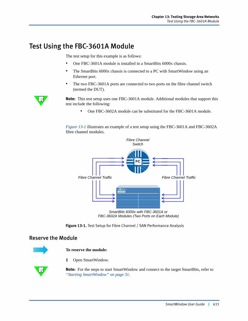
Chapter 13: Testing Storage Area NetworksTest Using the FBC-3601A Module
Test Using the FBC-3601A ModuleThe test setup for this example is as follows:
• One FBC-3601A module is installed in a SmartBits 6000x chassis.
• The SmartBits 6000x chassis is connected to a PC with SmartWindow using an Ethernet port.
• The two FBC-3601A ports are connected to two ports on the fibre channel switch (termed the DUT).
Note: This test setup uses one FBC-3601A module. Additional modules that support this test include the following:
• One FBC-3602A module can be substituted for the FBC-3601A module.
Figure 13-1 illustrates an example of a test setup using the FBC-3601A and FBC-3602A fibre channel modules.
Figure 13-1. Test Setup for Fibre Channel / SAN Performance Analysis
Reserve the Module
To reserve the module:
1 Open SmartWindow.
Note: For the steps to start SmartWindow and connect to the target SmartBits, refer to “Starting SmartWindow” on page 31.
FC
Fibre ChannelSwitch
Fibre Channel Traffic
SmartBits 6000x with FBC-3601A orFBC-3602A Modules (Two Ports on Each Module)
Fibre Channel Traffic
SmartWindow User Guide | 633
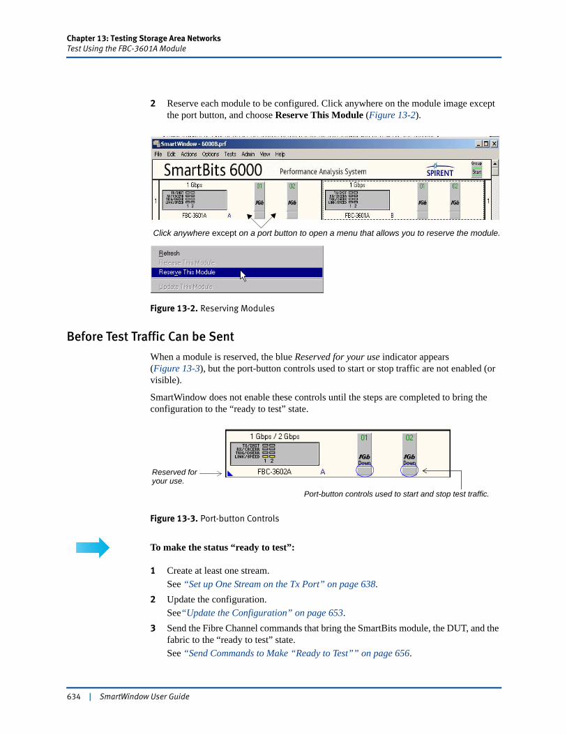
Chapter 13: Testing Storage Area NetworksTest Using the FBC-3601A Module
2 Reserve each module to be configured. Click anywhere on the module image except the port button, and choose Reserve This Module (Figure 13-2).
Figure 13-2. Reserving Modules
Before Test Traffic Can be Sent
When a module is reserved, the blue Reserved for your use indicator appears (Figure 13-3), but the port-button controls used to start or stop traffic are not enabled (or visible).
SmartWindow does not enable these controls until the steps are completed to bring the configuration to the “ready to test” state.
Figure 13-3. Port-button Controls
To make the status “ready to test”:
1 Create at least one stream.See “Set up One Stream on the Tx Port” on page 638.
2 Update the configuration.See“Update the Configuration” on page 653.
3 Send the Fibre Channel commands that bring the SmartBits module, the DUT, and the fabric to the “ready to test” state.See “Send Commands to Make “Ready to Test”” on page 656.
Click anywhere except on a port button to open a menu that allows you to reserve the module.
Port-button controls used to start and stop test traffic.
Reserved for your use.
634 | SmartWindow User Guide
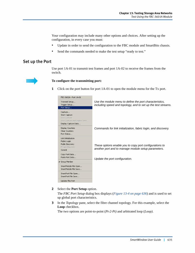
Chapter 13: Testing Storage Area NetworksTest Using the FBC-3601A Module
Your configuration may include many other options and choices. After setting up the configuration, in every case you must:
• Update in order to send the configuration to the FBC module and SmartBits chassis.
• Send the commands needed to make the test setup “ready to test.”
Set up the Port
Use port 1A-01 to transmit test frames and port 1A-02 to receive the frames from the switch.
To configure the transmitting port:
1 Click on the port button for port 1A-01 to open the module menu for the Tx port.
2 Select the Port Setup option.The FBC Port Setup dialog box displays (Figure 13-4 on page 636) and is used to set up global port characteristics.
3 In the Topology pane, select the fibre channel topology. For this example, select the Loop checkbox.The two options are point-to-point (Pt-2-Pt) and arbitrated loop (Loop).
Commands for link initialization, fabric login, and discovery.
These options enable you to copy port configurations toanother port and to manage module setup parameters.
Update the port configuration.
Use the module menu to define the port characteristics, including speed and topology, and to set up the test streams.
SmartWindow User Guide | 635
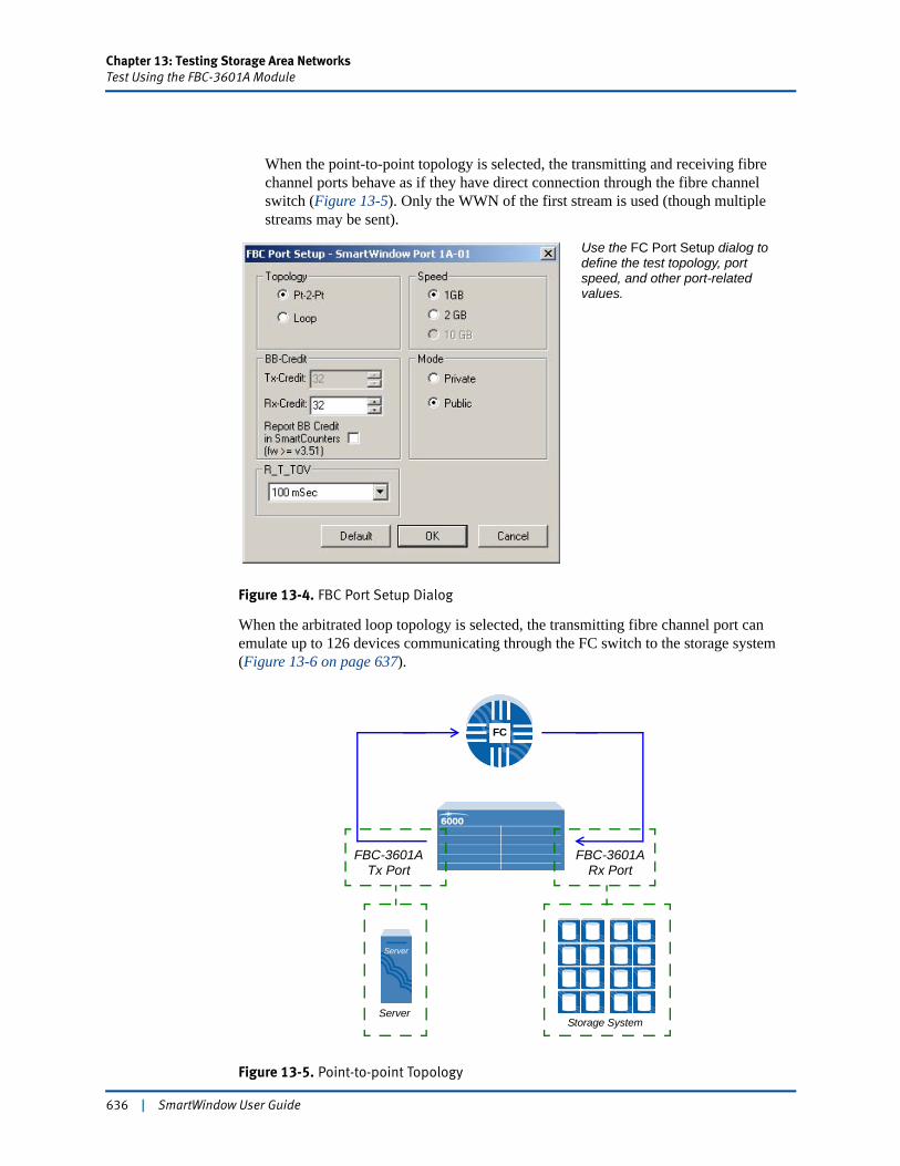
Chapter 13: Testing Storage Area NetworksTest Using the FBC-3601A Module
When the point-to-point topology is selected, the transmitting and receiving fibre channel ports behave as if they have direct connection through the fibre channel switch (Figure 13-5). Only the WWN of the first stream is used (though multiple streams may be sent).
Figure 13-4. FBC Port Setup Dialog
When the arbitrated loop topology is selected, the transmitting fibre channel port can emulate up to 126 devices communicating through the FC switch to the storage system (Figure 13-6 on page 637).
Figure 13-5. Point-to-point Topology
Use the FC Port Setup dialog todefine the test topology, port speed, and other port-relatedvalues.
FC
FBC-3601ATx Port
FBC-3601ARx Port
Storage SystemServer
Server
636 | SmartWindow User Guide
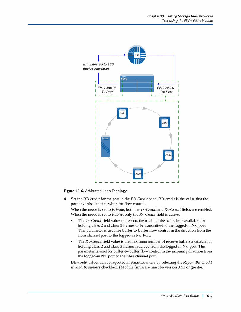
Chapter 13: Testing Storage Area NetworksTest Using the FBC-3601A Module
Figure 13-6. Arbitrated Loop Topology
4 Set the BB-credit for the port in the BB-Credit pane. BB-credit is the value that the port advertises to the switch for flow control.When the mode is set to Private, both the Tx-Credit and Rx-Credit fields are enabled. When the mode is set to Public, only the Rx-Credit field is active.• The Tx-Credit field value represents the total number of buffers available for
holding class 2 and class 3 frames to be transmitted to the logged-in Nx_port. This parameter is used for buffer-to-buffer flow control in the direction from the fibre channel port to the logged-in Nx_Port.
• The Rx-Credit field value is the maximum number of receive buffers available for holding class 2 and class 3 frames received from the logged-in Nx_port. This parameter is used for buffer-to-buffer flow control in the incoming direction from the logged-in Nx_port to the fibre channel port.
BB-credit values can be reported in SmartCounters by selecting the Report BB Credit in SmartCounters checkbox. (Module firmware must be version 3.51 or greater.)
FC
FBC-3601ATx Port
FBC-3601ARx Port
Disks
Disks
Server
Disks
Disks
Emulates up to 126device interfaces.
SmartWindow User Guide | 637

Chapter 13: Testing Storage Area NetworksTest Using the FBC-3601A Module
5 Set the port speed to either 1 Gbps (FBC-3601A or FBC-3602A) or 2 Gbps(FBC-3602A only).
6 Set the Mode to Private or Public. Guidelines are as follows:• Pt-2-Pt Public establishes a point-to-point connection between two devices
through a switch. This setting can be used to test “active” devices that respond to fibre channel signaling (such as FLOGI and PLOGI).
• Pt-2-Pt Private establishes a dedicated connection (link) between two devices. This setting can be used to test “passive” devices that do not respond to fibre channel signaling (such as FLOGI and PLOGI).
7 The Receiver_Transmitter_Timeout Value (R_T_TOV) is used by the receiver logic to detect loss of synchronization. The default value is 100ms. Select one of the defined values from the drop-down menu, if required.
8 When settings are correct, click OK.
Set up One Stream on the Tx Port
For this example, two streams are set up: one on the Tx port, and one on the Rx port. (See “Add a Stream on Port 1A-02” on page 650 for information on the receive port.) The FBC-360xA module is connected to a fibre channel switch.
To set up one stream:
Stream onport 1A-01
1 Click the port button and select Transmit Setup (Figure 13-7).The Streams Setup dialog box opens. The radio buttons in the Global Settings pane enable you to define the schedule mode.
2 Select gap-based traffic with the default interframe gap of six fibre channel words by clicking the IFG button and accepting the default of 6 in the Words field.
Note: See “Defining the Schedule Mode” on page 639 for a detailed description of how these options are used.
638 | SmartWindow User Guide
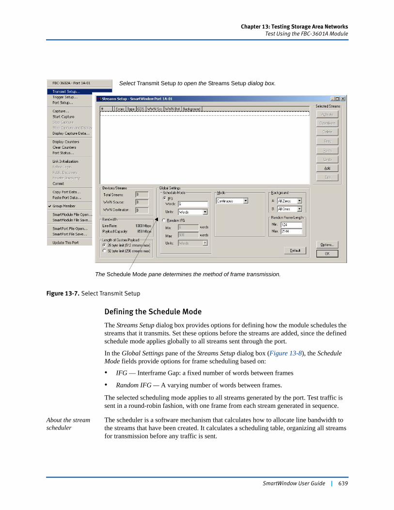
Chapter 13: Testing Storage Area NetworksTest Using the FBC-3601A Module
Figure 13-7. Select Transmit Setup
Defining the Schedule Mode
The Streams Setup dialog box provides options for defining how the module schedules the streams that it transmits. Set these options before the streams are added, since the defined schedule mode applies globally to all streams sent through the port.
In the Global Settings pane of the Streams Setup dialog box (Figure 13-8), the Schedule Mode fields provide options for frame scheduling based on:
• IFG — Interframe Gap: a fixed number of words between frames
• Random IFG — A varying number of words between frames.
The selected scheduling mode applies to all streams generated by the port. Test traffic is sent in a round-robin fashion, with one frame from each stream generated in sequence.
About the stream scheduler
The scheduler is a software mechanism that calculates how to allocate line bandwidth to the streams that have been created. It calculates a scheduling table, organizing all streams for transmission before any traffic is sent.
Select Transmit Setup to open the Streams Setup dialog box.
The Schedule Mode pane determines the method of frame transmission.
SmartWindow User Guide | 639
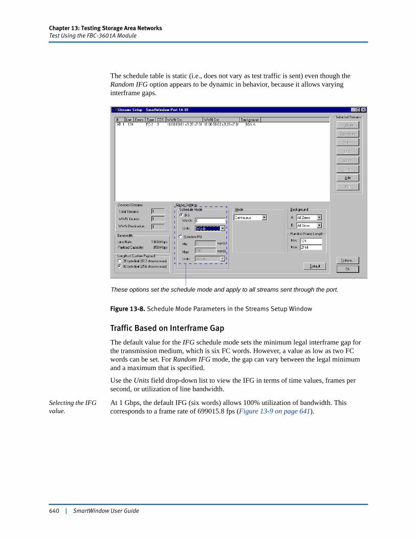
Chapter 13: Testing Storage Area NetworksTest Using the FBC-3601A Module
The schedule table is static (i.e., does not vary as test traffic is sent) even though the Random IFG option appears to be dynamic in behavior, because it allows varying interframe gaps.
Figure 13-8. Schedule Mode Parameters in the Streams Setup Window
Traffic Based on Interframe Gap
The default value for the IFG schedule mode sets the minimum legal interframe gap for the transmission medium, which is six FC words. However, a value as low as two FC words can be set. For Random IFG mode, the gap can vary between the legal minimum and a maximum that is specified.
Use the Units field drop-down list to view the IFG in terms of time values, frames per second, or utilization of line bandwidth.
Selecting the IFG value.
At 1 Gbps, the default IFG (six words) allows 100% utilization of bandwidth. This corresponds to a frame rate of 699015.8 fps (Figure 13-9 on page 641).
These options set the schedule mode and apply to all streams sent through the port.
640 | SmartWindow User Guide
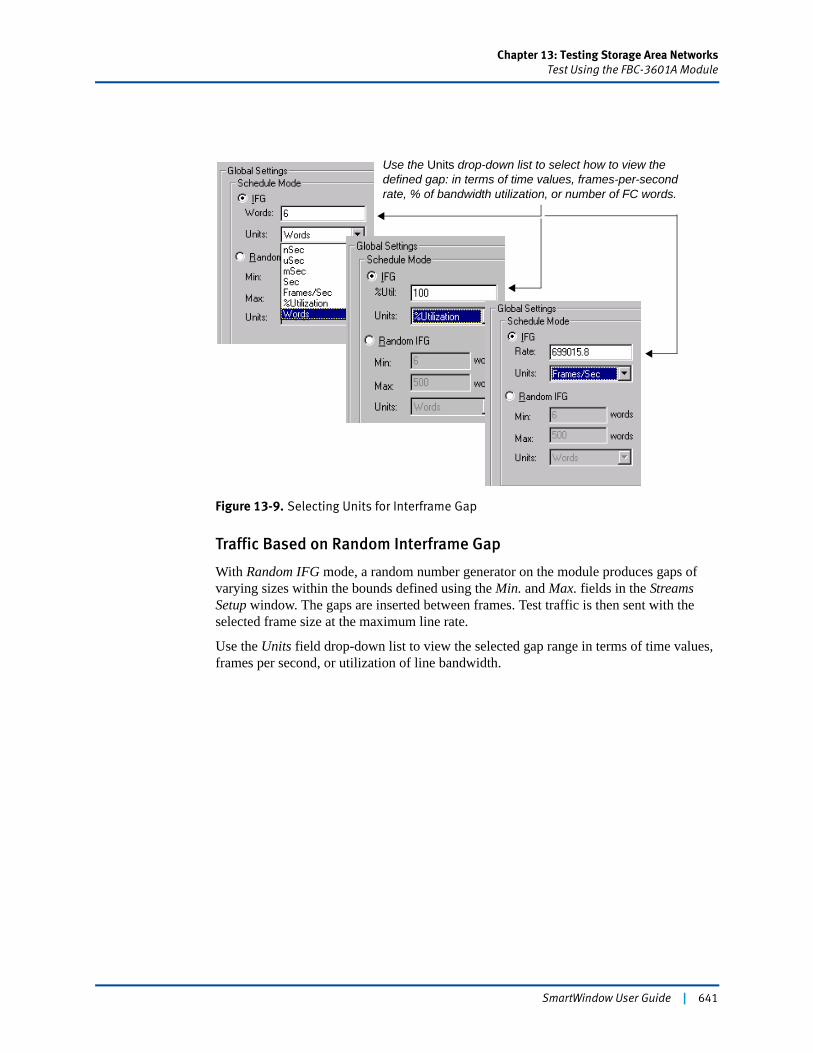
Chapter 13: Testing Storage Area NetworksTest Using the FBC-3601A Module
Figure 13-9. Selecting Units for Interframe Gap
Traffic Based on Random Interframe Gap
With Random IFG mode, a random number generator on the module produces gaps of varying sizes within the bounds defined using the Min. and Max. fields in the Streams Setup window. The gaps are inserted between frames. Test traffic is then sent with the selected frame size at the maximum line rate.
Use the Units field drop-down list to view the selected gap range in terms of time values, frames per second, or utilization of line bandwidth.
Use the Units drop-down list to select how to view the defined gap: in terms of time values, frames-per-second rate, % of bandwidth utilization, or number of FC words.
SmartWindow User Guide | 641
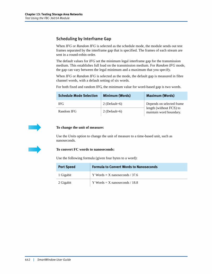
Chapter 13: Testing Storage Area NetworksTest Using the FBC-3601A Module
Scheduling by Interframe Gap
When IFG or Random IFG is selected as the schedule mode, the module sends out test frames separated by the interframe gap that is specified. The frames of each stream are sent in a round-robin order.
The default values for IFG set the minimum legal interframe gap for the transmission medium. This establishes full load on the transmission medium. For Random IFG mode, the gap can vary between the legal minimum and a maximum that you specify.
When IFG or Random IFG is selected as the mode, the default gap is measured in fibre channel words, with a default setting of six words.
For both fixed and random IFG, the minimum value for word-based gap is two words.
To change the unit of measure:
Use the Units option to change the unit of measure to a time-based unit, such as nanoseconds.
To convert FC words to nanoseconds:
Use the following formula (given four bytes to a word):
Schedule Mode Selection Minimum (Words) Maximum (Words)
IFG 2 (Default=6) Depends on selected frame length (without FCS) to maintain word boundary.Random IFG 2 (Default=6)
Port Speed Formula to Convert Words to Nanoseconds
1 Gigabit Y Words = X nanoseconds / 37.6
2 Gigabit Y Words = X nanoseconds / 18.8
642 | SmartWindow User Guide
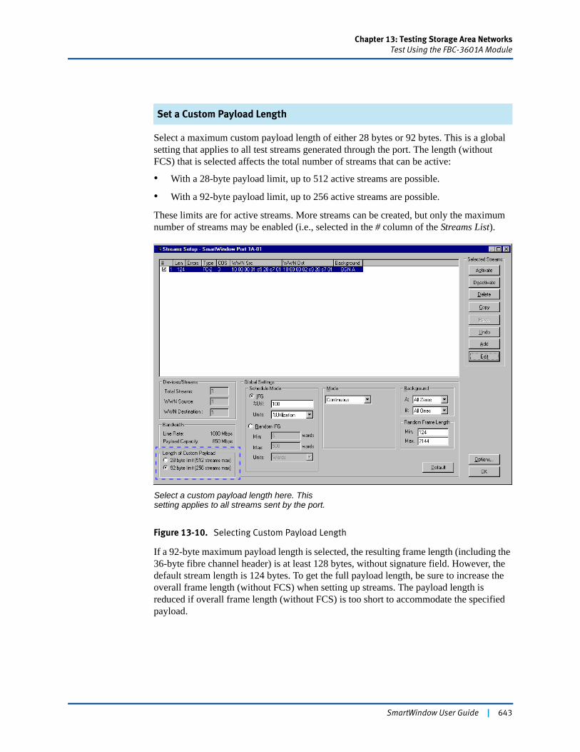
Chapter 13: Testing Storage Area NetworksTest Using the FBC-3601A Module
Set a Custom Payload Length
Select a maximum custom payload length of either 28 bytes or 92 bytes. This is a global setting that applies to all test streams generated through the port. The length (without FCS) that is selected affects the total number of streams that can be active:
• With a 28-byte payload limit, up to 512 active streams are possible.
• With a 92-byte payload limit, up to 256 active streams are possible.
These limits are for active streams. More streams can be created, but only the maximum number of streams may be enabled (i.e., selected in the # column of the Streams List).
Figure 13-10. Selecting Custom Payload Length
If a 92-byte maximum payload length is selected, the resulting frame length (including the 36-byte fibre channel header) is at least 128 bytes, without signature field. However, the default stream length is 124 bytes. To get the full payload length, be sure to increase the overall frame length (without FCS) when setting up streams. The payload length is reduced if overall frame length (without FCS) is too short to accommodate the specified payload.
Select a custom payload length here. This setting applies to all streams sent by the port.
SmartWindow User Guide | 643

Chapter 13: Testing Storage Area NetworksTest Using the FBC-3601A Module
Payload length with signature field
In addition, payload length is reduced by 18 bytes when the SmartMetrics Signature Field checkbox is selected. The Signature Field checkbox is selected by default. If needed, disable it by editing the stream and clearing the Signature Field checkbox. (See Figure 13-12 on page 646.)
To modify the payload contents:
Edit the payload contents by editing the stream definition.1 Highlight the stream entry, then click the Edit button in the Selected Streams pane.2 When the Tx Control Panel window opens, click the FC-2 button in the Edit Protocol
Stack pane.3 In the SETUP: FC-2 (Fibre Channel-2) Protocol pane, select the Customize Payload
checkbox, then click the Edit button.4 Use the Frame Editor to modify the contents of the frame payload.
Payload Length and Frame Length
In Figure 13-11 on page 645, the payload length is shown as 68 bytes, even though the maximum length of custom payload was set to 92. (See Figure 13-10 on page 643.) This payload length value is calculated as frame length (124 bytes) (without FCS) minus fibre channel frame header (36 bytes) minus the signature field (18 bytes), and rounded up to the four-byte boundary.
644 | SmartWindow User Guide
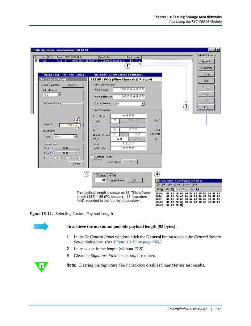
Chapter 13: Testing Storage Area NetworksTest Using the FBC-3601A Module
Figure 13-11. Selecting Custom Payload Length
To achieve the maximum possible payload length (92 bytes):
1 In the Tx Control Panel window, click the General button to open the General Stream Setup dialog box. (See Figure 13-12 on page 646.)
2 Increase the frame length (without FCS).3 Clear the Signature Field checkbox, if required.
Note: Clearing the Signature Field checkbox disables SmartMetrics test results.
1
1
3 4
2
The payload length is shown as 68. This is frame length (124) – 36 (FC header) – 18 (signature field), rounded to the four-byte boundary.
SmartWindow User Guide | 645
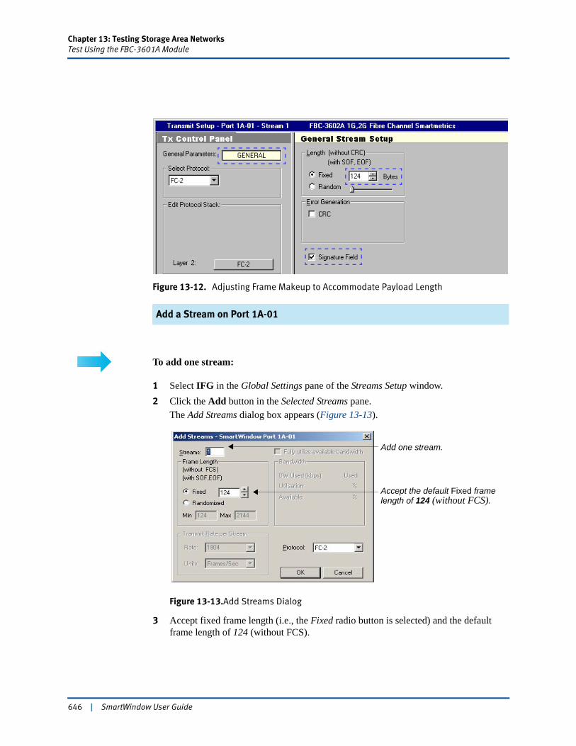
Chapter 13: Testing Storage Area NetworksTest Using the FBC-3601A Module
Figure 13-12. Adjusting Frame Makeup to Accommodate Payload Length
Add a Stream on Port 1A-01
To add one stream:
1 Select IFG in the Global Settings pane of the Streams Setup window.2 Click the Add button in the Selected Streams pane.
The Add Streams dialog box appears (Figure 13-13).
Figure 13-13.Add Streams Dialog
3 Accept fixed frame length (i.e., the Fixed radio button is selected) and the default frame length of 124 (without FCS).
Add one stream.
Accept the default Fixed framelength of 124 (without FCS).
646 | SmartWindow User Guide
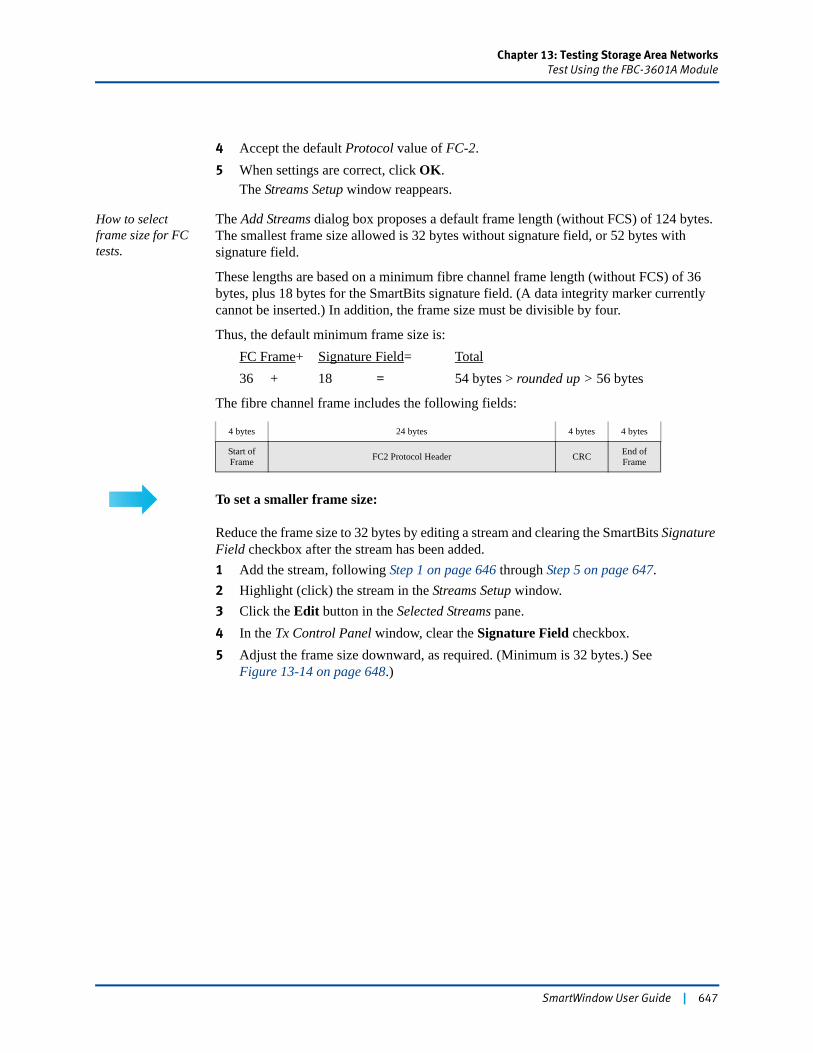
Chapter 13: Testing Storage Area NetworksTest Using the FBC-3601A Module
4 Accept the default Protocol value of FC-2.5 When settings are correct, click OK.
The Streams Setup window reappears.
How to select frame size for FC tests.
The Add Streams dialog box proposes a default frame length (without FCS) of 124 bytes. The smallest frame size allowed is 32 bytes without signature field, or 52 bytes with signature field.
These lengths are based on a minimum fibre channel frame length (without FCS) of 36 bytes, plus 18 bytes for the SmartBits signature field. (A data integrity marker currently cannot be inserted.) In addition, the frame size must be divisible by four.
Thus, the default minimum frame size is:FC Frame+ Signature Field= Total36 + 18 = 54 bytes > rounded up > 56 bytes
The fibre channel frame includes the following fields:
To set a smaller frame size:
Reduce the frame size to 32 bytes by editing a stream and clearing the SmartBits Signature Field checkbox after the stream has been added. 1 Add the stream, following Step 1 on page 646 through Step 5 on page 647.2 Highlight (click) the stream in the Streams Setup window.3 Click the Edit button in the Selected Streams pane.4 In the Tx Control Panel window, clear the Signature Field checkbox.5 Adjust the frame size downward, as required. (Minimum is 32 bytes.) See
Figure 13-14 on page 648.)
4 bytes 24 bytes 4 bytes 4 bytes
Start of Frame FC2 Protocol Header CRC End of
Frame
SmartWindow User Guide | 647
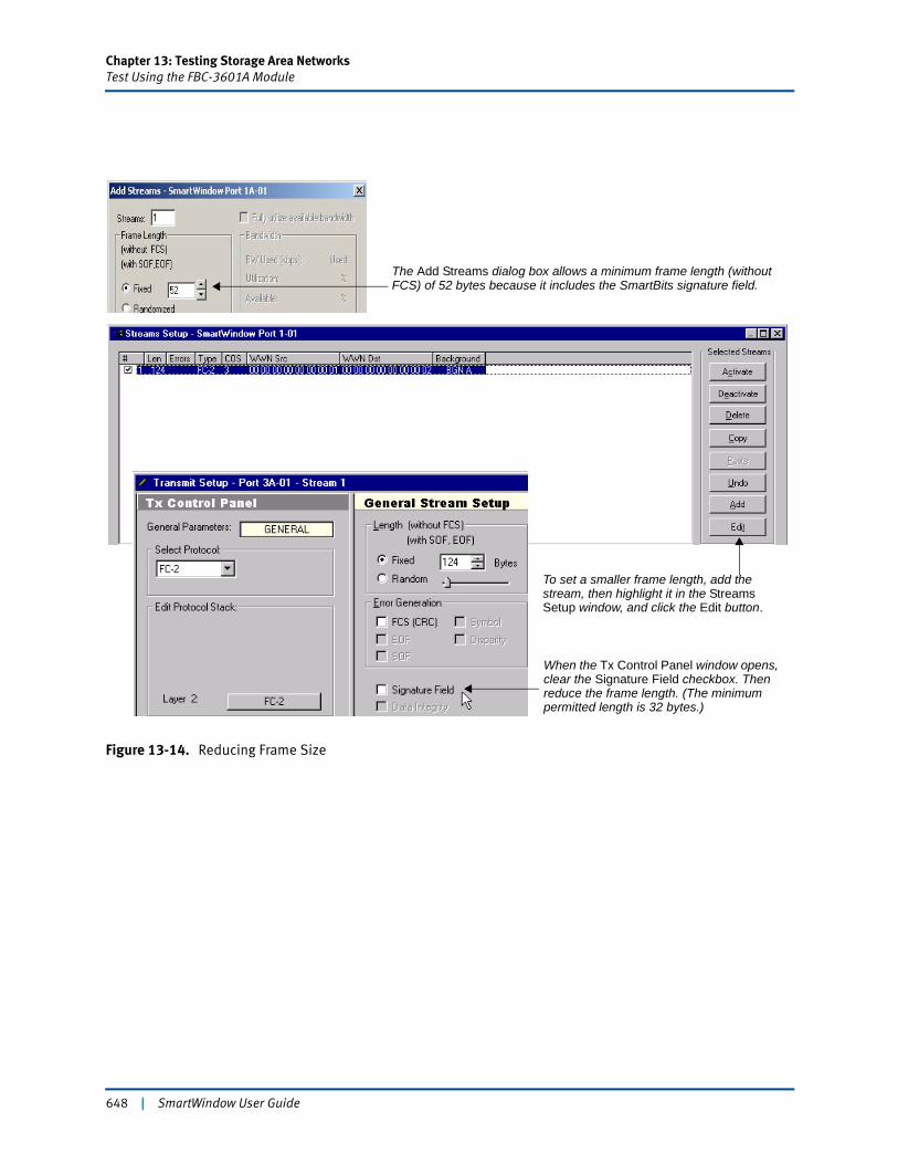
Chapter 13: Testing Storage Area NetworksTest Using the FBC-3601A Module
Figure 13-14. Reducing Frame Size
The Add Streams dialog box allows a minimum frame length (without FCS) of 52 bytes because it includes the SmartBits signature field.
To set a smaller frame length, add the stream, then highlight it in the Streams Setup window, and click the Edit button.
When the Tx Control Panel window opens, clear the Signature Field checkbox. Then reduce the frame length. (The minimum permitted length is 32 bytes.)
648 | SmartWindow User Guide
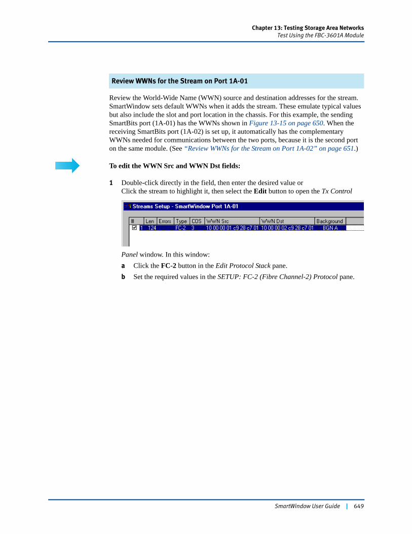
Chapter 13: Testing Storage Area NetworksTest Using the FBC-3601A Module
Review WWNs for the Stream on Port 1A-01
Review the World-Wide Name (WWN) source and destination addresses for the stream. SmartWindow sets default WWNs when it adds the stream. These emulate typical values but also include the slot and port location in the chassis. For this example, the sending SmartBits port (1A-01) has the WWNs shown in Figure 13-15 on page 650. When the receiving SmartBits port (1A-02) is set up, it automatically has the complementary WWNs needed for communications between the two ports, because it is the second port on the same module. (See “Review WWNs for the Stream on Port 1A-02” on page 651.)
To edit the WWN Src and WWN Dst fields:
1 Double-click directly in the field, then enter the desired value orClick the stream to highlight it, then select the Edit button to open the Tx Control
Panel window. In this window:a Click the FC-2 button in the Edit Protocol Stack pane.b Set the required values in the SETUP: FC-2 (Fibre Channel-2) Protocol pane.
SmartWindow User Guide | 649

Chapter 13: Testing Storage Area NetworksTest Using the FBC-3601A Module
Figure 13-15. Default WWNs for Transmitting Port 1A-01
Add a Stream on Port 1A-02
Configure the port and stream for receiving port 1A-02.
To add a stream on port 1A-02:
1 Click the port button 02 on the FBC-3601A module.2 Select Port Setup, and repeat the port setup that was performed for the transmitting
port 1A-01. (See “Set up the Port” on page 635.)3 Select Transmit Setup from the module menu to open the Streams Setup window.4 Click the Add button in the Selected Streams pane.5 Use the Add Streams dialog box to add one stream with the same characteristics that
were applied in “Add a Stream on Port 1A-01” on page 646.6 When settings are correct, click OK to return to the Streams Setup window.
Click the FC-2 button to openthe SETUP pane for the FC-2(Fibre Channel-2) protocol.
Use the Address Service Type pane to edit the values for WWNsource and destination addresses.
650 | SmartWindow User Guide
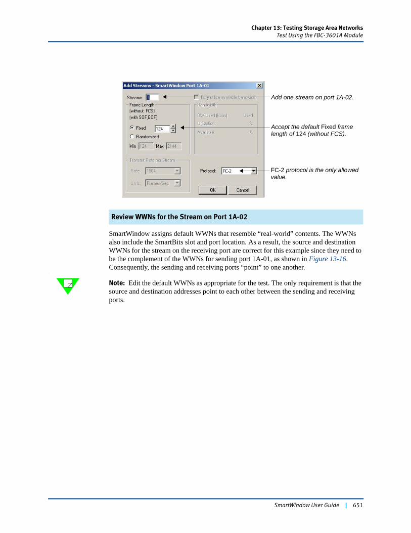
Chapter 13: Testing Storage Area NetworksTest Using the FBC-3601A Module
Review WWNs for the Stream on Port 1A-02
SmartWindow assigns default WWNs that resemble “real-world” contents. The WWNs also include the SmartBits slot and port location. As a result, the source and destination WWNs for the stream on the receiving port are correct for this example since they need to be the complement of the WWNs for sending port 1A-01, as shown in Figure 13-16. Consequently, the sending and receiving ports “point” to one another.
\
Note: Edit the default WWNs as appropriate for the test. The only requirement is that the source and destination addresses point to each other between the sending and receiving ports.
Accept the default Fixed framelength of 124 (without FCS).
FC-2 protocol is the only allowed
Add one stream on port 1A-02.
value.
SmartWindow User Guide | 651
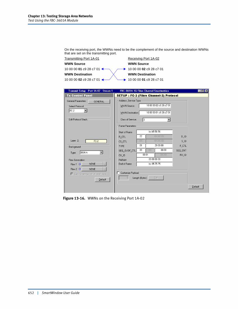
Chapter 13: Testing Storage Area NetworksTest Using the FBC-3601A Module
Figure 13-16. WWNs on the Receiving Port 1A-02
On the receiving port, the WWNs need to be the complement of the source and destination WWNs that are set on the transmitting port.Transmitting Port 1A-01 Receiving Port 1A-02WWN Source WWN Source10 00 00 01 c9 28 c7 01 10 00 00 02 c9 28 c7 01WWN Destination WWN Destination10 00 00 02 c9 28 c7 01 10 00 00 01 c9 28 c7 01
652 | SmartWindow User Guide
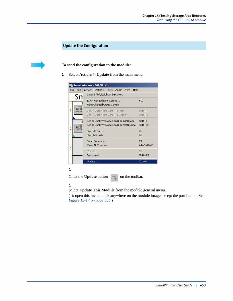
Chapter 13: Testing Storage Area NetworksTest Using the FBC-3601A Module
Update the Configuration
To send the configuration to the module:
1 Select Actions > Update from the main menu.
Or
Click the Update button on the toolbar.
OrSelect Update This Module from the module general menu.(To open this menu, click anywhere on the module image except the port button. See Figure 13-17 on page 654.)
SmartWindow User Guide | 653
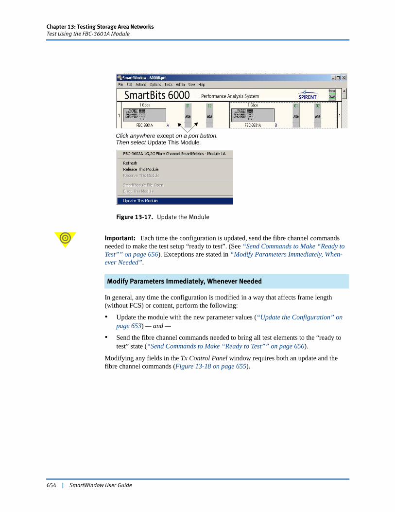
Chapter 13: Testing Storage Area NetworksTest Using the FBC-3601A Module
Figure 13-17. Update the Module
Important: Each time the configuration is updated, send the fibre channel commands needed to make the test setup “ready to test”. (See “Send Commands to Make “Ready to Test”” on page 656). Exceptions are stated in “Modify Parameters Immediately, When-ever Needed”.
Modify Parameters Immediately, Whenever Needed
In general, any time the configuration is modified in a way that affects frame length (without FCS) or content, perform the following:
• Update the module with the new parameter values (“Update the Configuration” on page 653) — and —
• Send the fibre channel commands needed to bring all test elements to the “ready to test” state (“Send Commands to Make “Ready to Test”” on page 656).
Modifying any fields in the Tx Control Panel window requires both an update and the fibre channel commands (Figure 13-18 on page 655).
Click anywhere except on a port button.Then select Update This Module.
654 | SmartWindow User Guide
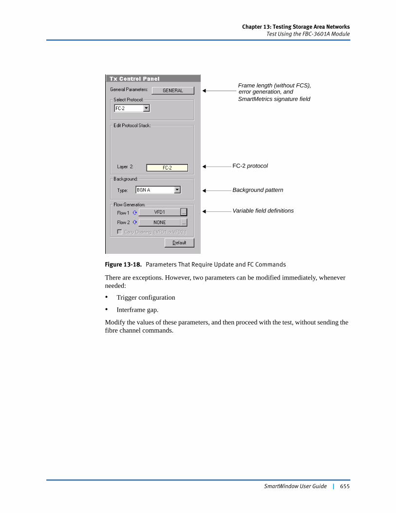
Chapter 13: Testing Storage Area NetworksTest Using the FBC-3601A Module
Figure 13-18. Parameters That Require Update and FC Commands
There are exceptions. However, two parameters can be modified immediately, whenever needed:
• Trigger configuration
• Interframe gap.
Modify the values of these parameters, and then proceed with the test, without sending the fibre channel commands.
FC-2 protocol
Background pattern
Variable field definitions
Frame length (without FCS),
SmartMetrics signature field error generation, and
SmartWindow User Guide | 655
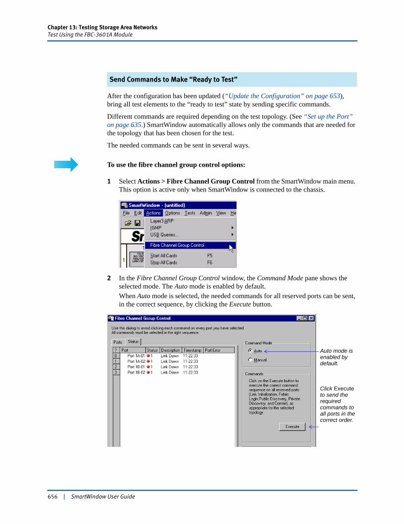
Chapter 13: Testing Storage Area NetworksTest Using the FBC-3601A Module
Send Commands to Make “Ready to Test”
After the configuration has been updated (“Update the Configuration” on page 653), bring all test elements to the “ready to test” state by sending specific commands.
Different commands are required depending on the test topology. (See “Set up the Port” on page 635.) SmartWindow automatically allows only the commands that are needed for the topology that has been chosen for the test.
The needed commands can be sent in several ways.
To use the fibre channel group control options:
1 Select Actions > Fibre Channel Group Control from the SmartWindow main menu. This option is active only when SmartWindow is connected to the chassis.
2 In the Fibre Channel Group Control window, the Command Mode pane shows the selected mode. The Auto mode is enabled by default.When Auto mode is selected, the needed commands for all reserved ports can be sent, in the correct sequence, by clicking the Execute button.
Auto mode is enabled by default.
Click Execute to send the required commands to all ports in the correct order.
656 | SmartWindow User Guide
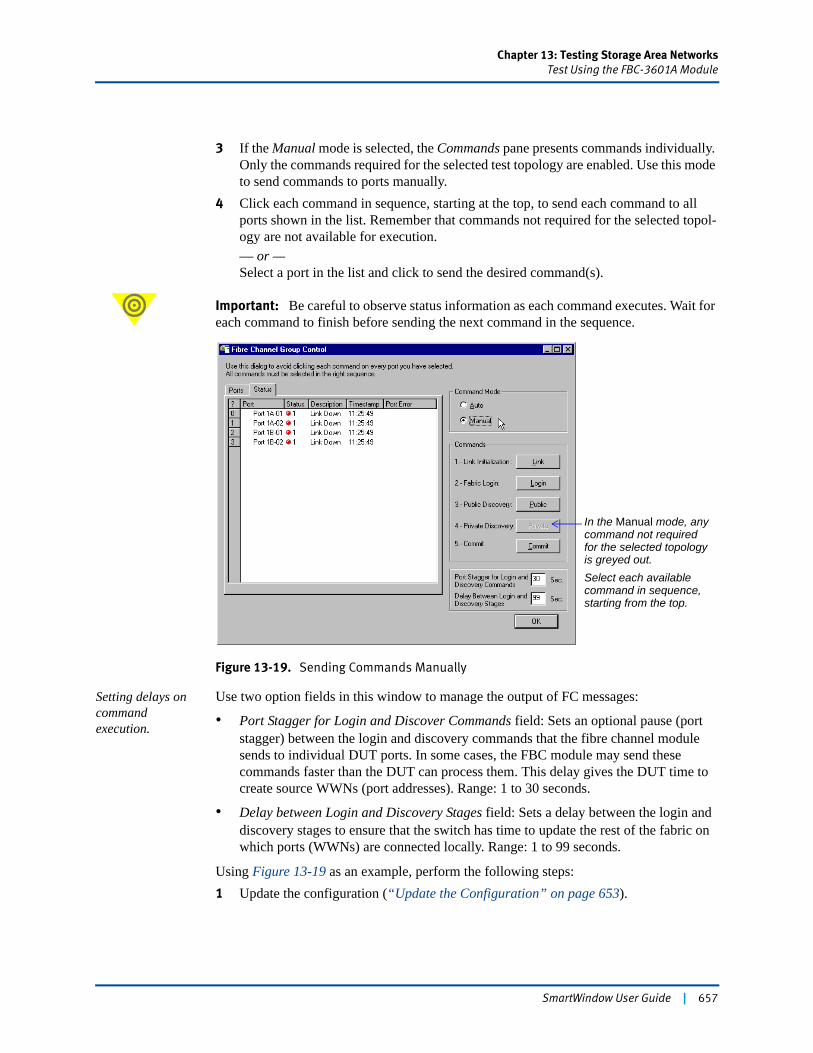
Chapter 13: Testing Storage Area NetworksTest Using the FBC-3601A Module
3 If the Manual mode is selected, the Commands pane presents commands individually. Only the commands required for the selected test topology are enabled. Use this mode to send commands to ports manually.
4 Click each command in sequence, starting at the top, to send each command to all ports shown in the list. Remember that commands not required for the selected topol-ogy are not available for execution.— or — Select a port in the list and click to send the desired command(s).
Important: Be careful to observe status information as each command executes. Wait for each command to finish before sending the next command in the sequence.
Figure 13-19. Sending Commands Manually
Setting delays on command execution.
Use two option fields in this window to manage the output of FC messages:
• Port Stagger for Login and Discover Commands field: Sets an optional pause (port stagger) between the login and discovery commands that the fibre channel module sends to individual DUT ports. In some cases, the FBC module may send these commands faster than the DUT can process them. This delay gives the DUT time to create source WWNs (port addresses). Range: 1 to 30 seconds.
• Delay between Login and Discovery Stages field: Sets a delay between the login and discovery stages to ensure that the switch has time to update the rest of the fabric on which ports (WWNs) are connected locally. Range: 1 to 99 seconds.
Using Figure 13-19 as an example, perform the following steps:1 Update the configuration (“Update the Configuration” on page 653).
In the Manual mode, any command not required for the selected topology is greyed out.Select each available command in sequence, starting from the top.
SmartWindow User Guide | 657
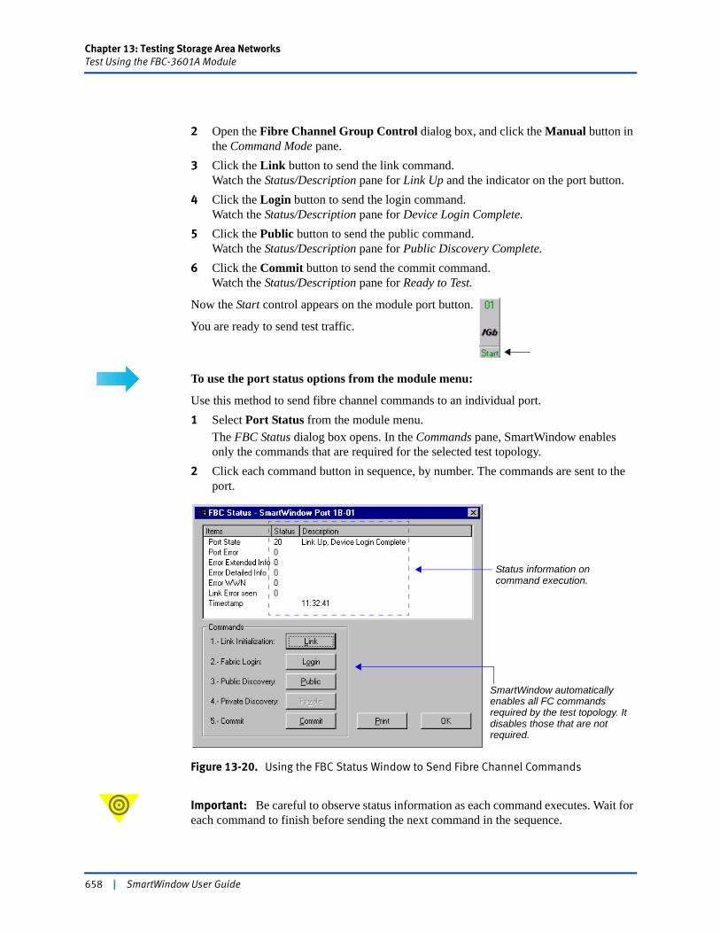
Chapter 13: Testing Storage Area NetworksTest Using the FBC-3601A Module
2 Open the Fibre Channel Group Control dialog box, and click the Manual button in the Command Mode pane.
3 Click the Link button to send the link command.Watch the Status/Description pane for Link Up and the indicator on the port button.
4 Click the Login button to send the login command.Watch the Status/Description pane for Device Login Complete.
5 Click the Public button to send the public command.Watch the Status/Description pane for Public Discovery Complete.
6 Click the Commit button to send the commit command.Watch the Status/Description pane for Ready to Test.
Now the Start control appears on the module port button.
You are ready to send test traffic.
To use the port status options from the module menu:
Use this method to send fibre channel commands to an individual port.1 Select Port Status from the module menu.
The FBC Status dialog box opens. In the Commands pane, SmartWindow enables only the commands that are required for the selected test topology.
2 Click each command button in sequence, by number. The commands are sent to the port.
Figure 13-20. Using the FBC Status Window to Send Fibre Channel Commands
Important: Be careful to observe status information as each command executes. Wait for each command to finish before sending the next command in the sequence.
Status information on command execution.
SmartWindow automatically enables all FC commands required by the test topology. It disables those that are not required.
658 | SmartWindow User Guide
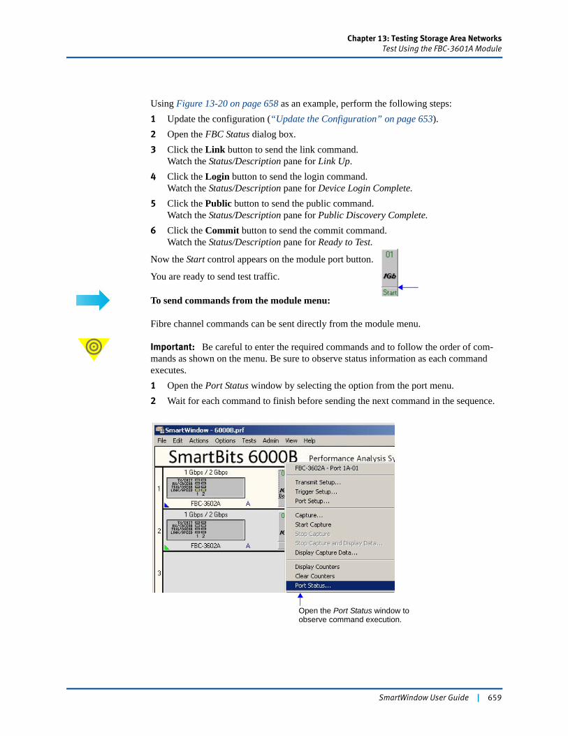
Chapter 13: Testing Storage Area NetworksTest Using the FBC-3601A Module
Using Figure 13-20 on page 658 as an example, perform the following steps:1 Update the configuration (“Update the Configuration” on page 653).2 Open the FBC Status dialog box. 3 Click the Link button to send the link command.
Watch the Status/Description pane for Link Up.4 Click the Login button to send the login command.
Watch the Status/Description pane for Device Login Complete.5 Click the Public button to send the public command.
Watch the Status/Description pane for Public Discovery Complete.6 Click the Commit button to send the commit command.
Watch the Status/Description pane for Ready to Test.
Now the Start control appears on the module port button.
You are ready to send test traffic.
To send commands from the module menu:
Fibre channel commands can be sent directly from the module menu.
Important: Be careful to enter the required commands and to follow the order of com-mands as shown on the menu. Be sure to observe status information as each command executes. 1 Open the Port Status window by selecting the option from the port menu. 2 Wait for each command to finish before sending the next command in the sequence.
Open the Port Status window to observe command execution.
SmartWindow User Guide | 659
Chapter 13: Testing Storage Area NetworksSend Traffic and View Counters
Send Traffic and View CountersFor complete information on SmartCounters, see Table 13-2 for a listing of locations in this manual that describe how to display, configure, and run SmartCounters.
Choosing Actions > SmartCounters enables you to view SmartCounters.
After you’ve completed the necessary set up and configuration steps, initiate the test and review the initial data. As the test is run, watch the counters on the receive port.
Note: In fibre channel transmissions, frame sizes can be up to 16,384 bytes, including CRC. This value is displayed in the counters using the constructs described in Table 13-3.
On the receive port, the frame count includes frames greater than 2,152 bytes (with CRC) as Rx oversize frames and not as Rx frames. Received oversized frames are not counted as Rx frames but counted as Rx oversize frames. If the received frame size is less than 2,152 bytes, then it is counted as an Rx frame.
Table 13-3. Fibre Channel Frame Sizes for Oversized Frames
To begin transmission of the SmartWindow front panel:
1 Click the Start button on the transmitting FBC port 1A-01.
Table 13-2. Information on SmartCounters
Information Location
Design of SmartCounters “SmartCounters Structure” on page 416
Pre-defined views “Results Framework” on page 417
Setting formulas Step 4 on page 427
Running SmartCounters “Running SmartCounters” on page 435
Frame Construct Description
Tx frames Tx frames and no Rx frames
Tx frame rate Tx frame rate and not Rx frame rate
Tx class 2/3 frames Tx class 2/3 frames and no Rx Class 2/3 frames
Rx oversize frames Rx oversized frames and no Tx oversized frames
660 | SmartWindow User Guide
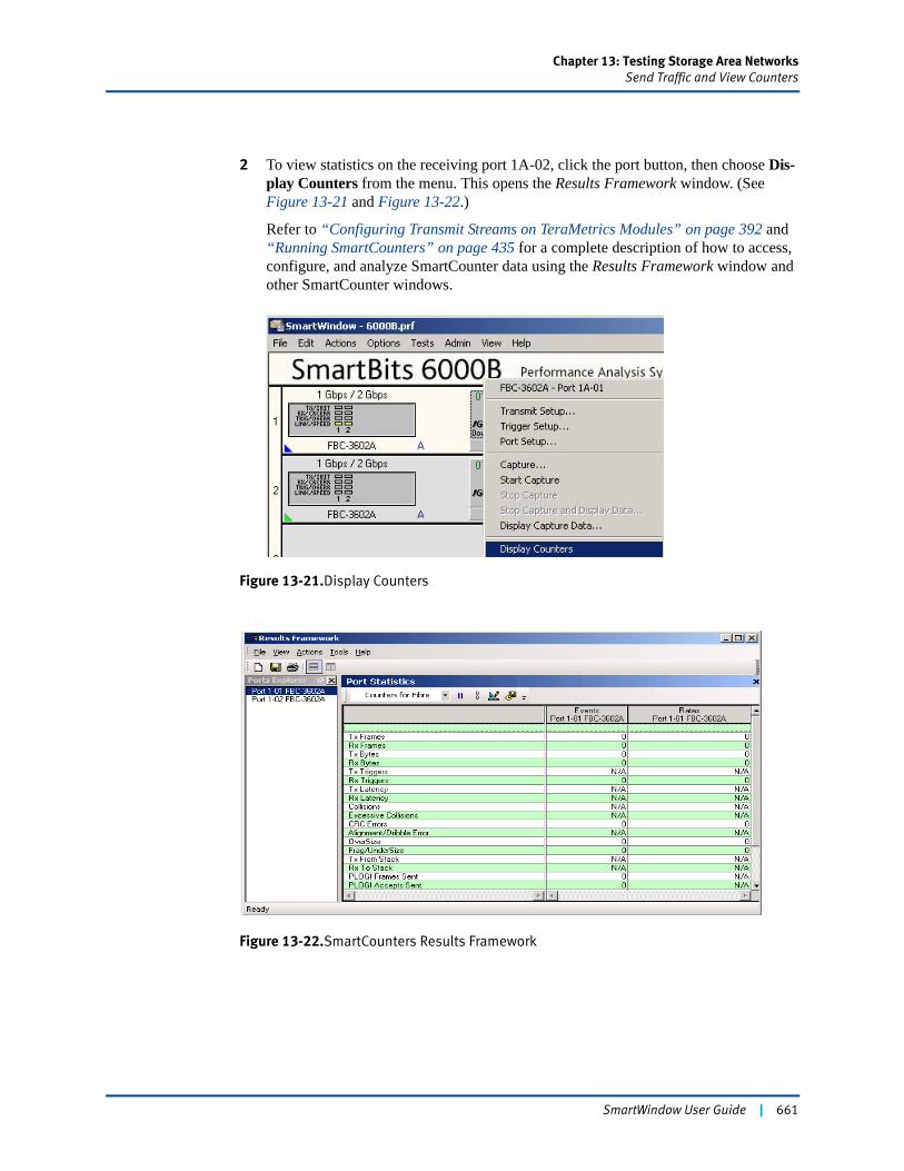
Chapter 13: Testing Storage Area NetworksSend Traffic and View Counters
2 To view statistics on the receiving port 1A-02, click the port button, then choose Dis-play Counters from the menu. This opens the Results Framework window. (See Figure 13-21 and Figure 13-22.)
Refer to “Configuring Transmit Streams on TeraMetrics Modules” on page 392 and “Running SmartCounters” on page 435 for a complete description of how to access, configure, and analyze SmartCounter data using the Results Framework window and other SmartCounter windows.
Figure 13-21.Display Counters
Figure 13-22.SmartCounters Results Framework
SmartWindow User Guide | 661
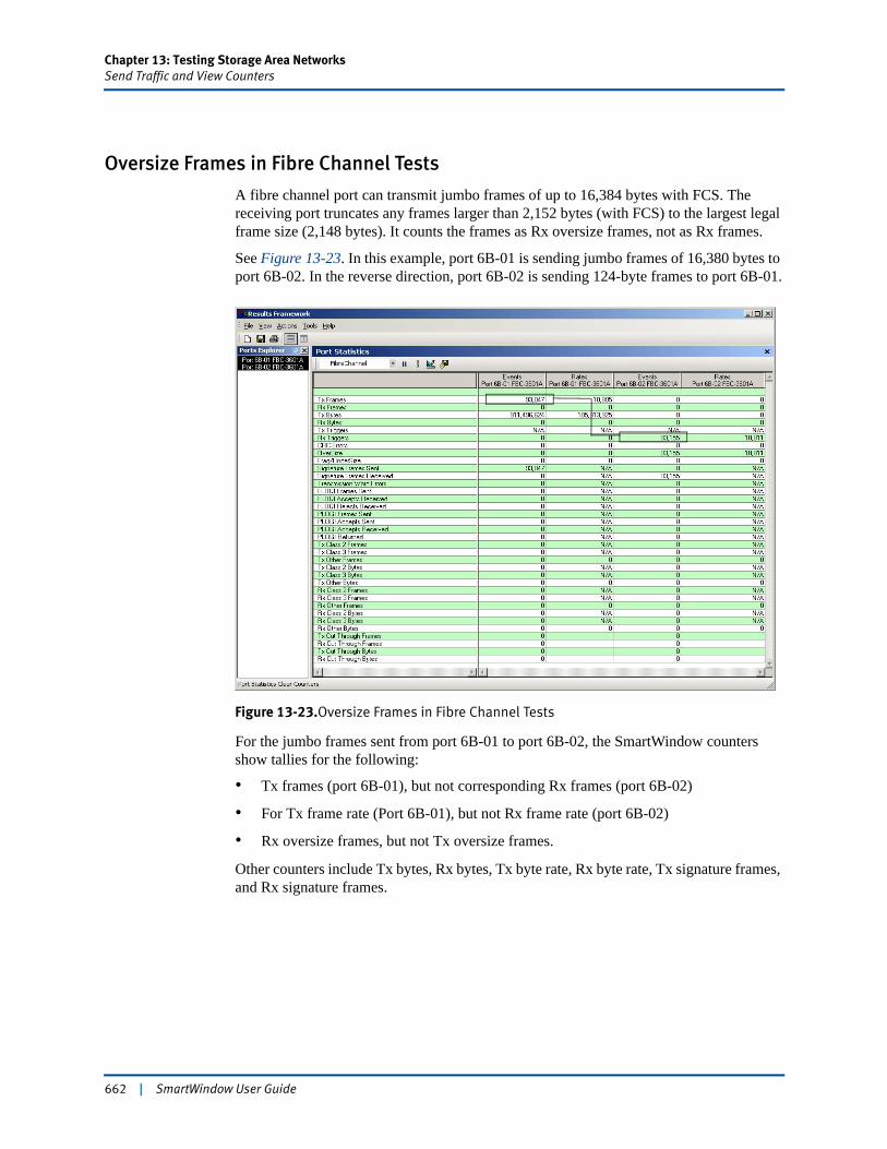
Chapter 13: Testing Storage Area NetworksSend Traffic and View Counters
Oversize Frames in Fibre Channel Tests
A fibre channel port can transmit jumbo frames of up to 16,384 bytes with FCS. The receiving port truncates any frames larger than 2,152 bytes (with FCS) to the largest legal frame size (2,148 bytes). It counts the frames as Rx oversize frames, not as Rx frames.
See Figure 13-23. In this example, port 6B-01 is sending jumbo frames of 16,380 bytes to port 6B-02. In the reverse direction, port 6B-02 is sending 124-byte frames to port 6B-01.
Figure 13-23.Oversize Frames in Fibre Channel Tests
For the jumbo frames sent from port 6B-01 to port 6B-02, the SmartWindow counters show tallies for the following:
• Tx frames (port 6B-01), but not corresponding Rx frames (port 6B-02)
• For Tx frame rate (Port 6B-01), but not Rx frame rate (port 6B-02)
• Rx oversize frames, but not Tx oversize frames.
Other counters include Tx bytes, Rx bytes, Tx byte rate, Rx byte rate, Tx signature frames, and Rx signature frames.
662 | SmartWindow User Guide
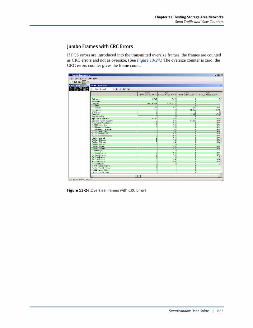
Chapter 13: Testing Storage Area NetworksSend Traffic and View Counters
Jumbo Frames with CRC Errors
If FCS errors are introduced into the transmitted oversize frames, the frames are counted as CRC errors and not as oversize. (See Figure 13-24.) The oversize counter is zero; the CRC errors counter gives the frame count.
Figure 13-24.Oversize Frames with CRC Errors
SmartWindow User Guide | 663
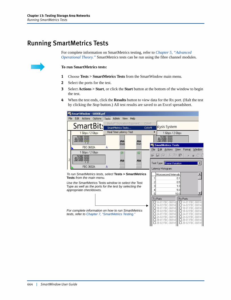
Chapter 13: Testing Storage Area NetworksRunning SmartMetrics Tests
Running SmartMetrics TestsFor complete information on SmartMetrics testing, refer to Chapter 5, “Advanced Operational Theory.” SmartMetrics tests can be run using the fibre channel modules.
To run SmartMetrics tests:
1 Choose Tests > SmartMetrics Tests from the SmartWindow main menu.2 Select the ports for the test.3 Select Actions > Start, or click the Start button at the bottom of the window to begin
the test.4 When the test ends, click the Results button to view data for the Rx port. (Halt the test
by clicking the Stop button.) All test results are saved to an Excel spreadsheet.
To run SmartMetrics tests, select Tests > SmartMetrics Tests from the main menu.Use the SmartMetrics Tests window to select the Test Type as well as the ports for the test by selecting the appropriate checkboxes.
For complete information on how to run SmartMetrics tests, refer to Chapter 7, “SmartMetrics Testing.”
664 | SmartWindow User Guide
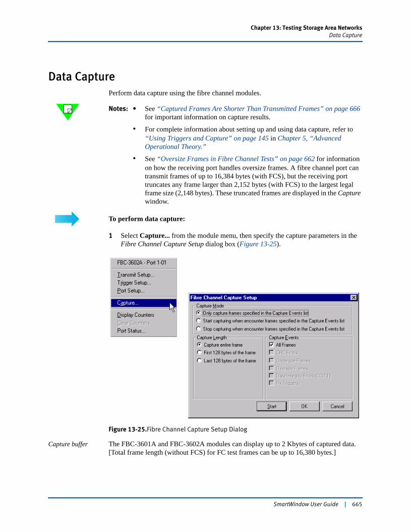
Chapter 13: Testing Storage Area NetworksData Capture
Data CapturePerform data capture using the fibre channel modules.
Notes: • See “Captured Frames Are Shorter Than Transmitted Frames” on page 666 for important information on capture results.
• For complete information about setting up and using data capture, refer to “Using Triggers and Capture” on page 145 in Chapter 5, “Advanced Operational Theory.”
• See “Oversize Frames in Fibre Channel Tests” on page 662 for information on how the receiving port handles oversize frames. A fibre channel port can transmit frames of up to 16,384 bytes (with FCS), but the receiving port truncates any frame larger than 2,152 bytes (with FCS) to the largest legal frame size (2,148 bytes). These truncated frames are displayed in the Capture window.
To perform data capture:
1 Select Capture... from the module menu, then specify the capture parameters in the Fibre Channel Capture Setup dialog box (Figure 13-25).
Figure 13-25.Fibre Channel Capture Setup Dialog
Capture buffer The FBC-3601A and FBC-3602A modules can display up to 2 Kbytes of captured data. [Total frame length (without FCS) for FC test frames can be up to 16,380 bytes.]
SmartWindow User Guide | 665
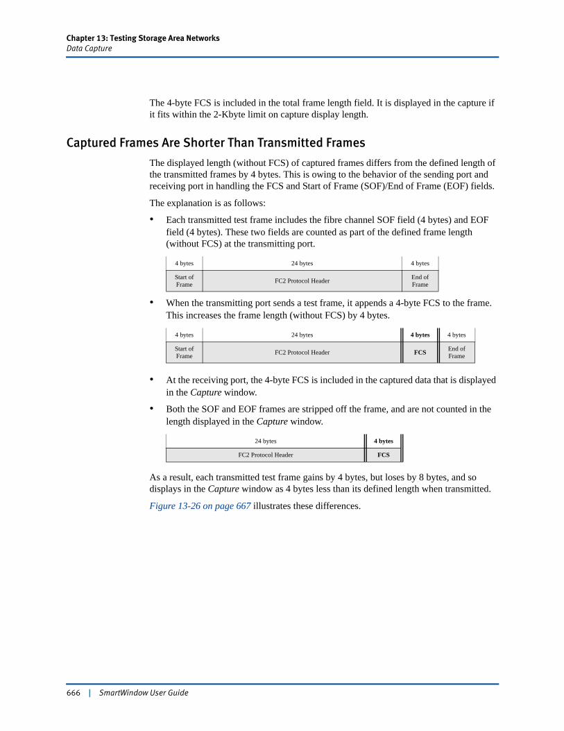
Chapter 13: Testing Storage Area NetworksData Capture
The 4-byte FCS is included in the total frame length field. It is displayed in the capture if it fits within the 2-Kbyte limit on capture display length.
Captured Frames Are Shorter Than Transmitted Frames
The displayed length (without FCS) of captured frames differs from the defined length of the transmitted frames by 4 bytes. This is owing to the behavior of the sending port and receiving port in handling the FCS and Start of Frame (SOF)/End of Frame (EOF) fields.
The explanation is as follows:
• Each transmitted test frame includes the fibre channel SOF field (4 bytes) and EOF field (4 bytes). These two fields are counted as part of the defined frame length (without FCS) at the transmitting port.
• When the transmitting port sends a test frame, it appends a 4-byte FCS to the frame. This increases the frame length (without FCS) by 4 bytes.
• At the receiving port, the 4-byte FCS is included in the captured data that is displayed in the Capture window.
• Both the SOF and EOF frames are stripped off the frame, and are not counted in the length displayed in the Capture window.
As a result, each transmitted test frame gains by 4 bytes, but loses by 8 bytes, and so displays in the Capture window as 4 bytes less than its defined length when transmitted.
Figure 13-26 on page 667 illustrates these differences.
4 bytes 24 bytes 4 bytes
Start of Frame FC2 Protocol Header End of
Frame
4 bytes 24 bytes 4 bytes 4 bytes
Start of Frame FC2 Protocol Header FCS End of
Frame
24 bytes 4 bytes
FC2 Protocol Header FCS
666 | SmartWindow User Guide
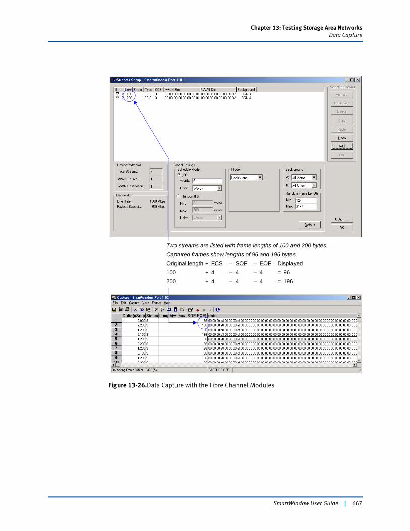
Chapter 13: Testing Storage Area NetworksData Capture
Figure 13-26.Data Capture with the Fibre Channel Modules
Two streams are listed with frame lengths of 100 and 200 bytes.Captured frames show lengths of 96 and 196 bytes.Original length + FCS – SOF – EOF Displayed100 + 4 – 4 – 4 = 96200 + 4 – 4 – 4 = 196
SmartWindow User Guide | 667

668 | SmartWindow User Guide
Appendix A
Supported Cards and Modules
SmartWindow currently supports and manages the SmartCards and modules itemized in this appendix.
Detailed Card and Module InformationFor more complete system hardware information, refer to:
• SmartBits System Reference Guide
• SmartBits 600x/6000x Getting Started
• SmartBits 200/2000 Installation Guide.
Firmware RequirementsRefer to the Release Notes included with your product for the latest information on required firmware versions for chassis, cards, and modules.
Card DesignationsCard and module names are keyed to the SmartBits chassis in which the card is used.
Card Designation Chassis Example of Card or Module Name
AB-xxxxN SmartBits 200/2000 ML-7710
ABC-3xxxN SmartBits 600x/6000x POS-3505AR/As
SmartWindow User Guide | 669
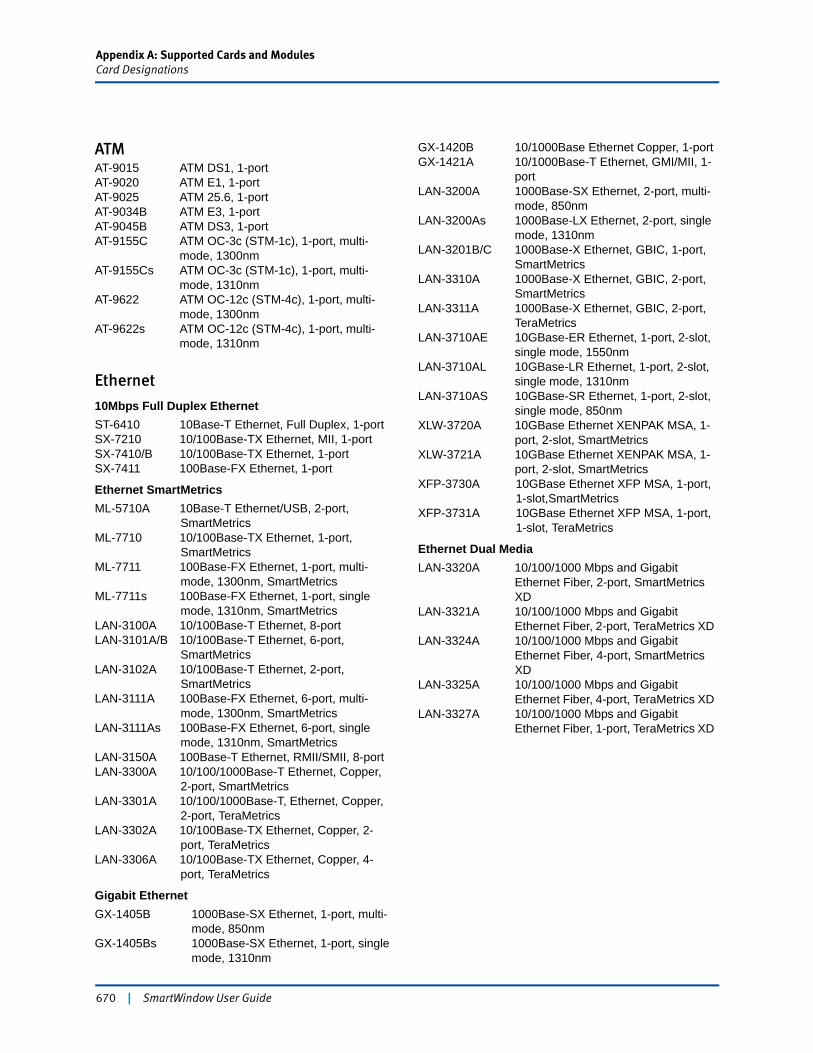
Appendix A: Supported Cards and ModulesCard Designations
670 | SmartWindow User Guide
ATMAT-9015 ATM DS1, 1-portAT-9020 ATM E1, 1-portAT-9025 ATM 25.6, 1-portAT-9034B ATM E3, 1-portAT-9045B ATM DS3, 1-portAT-9155C ATM OC-3c (STM-1c), 1-port, multi-
mode, 1300nmAT-9155Cs ATM OC-3c (STM-1c), 1-port, multi-
mode, 1310nmAT-9622 ATM OC-12c (STM-4c), 1-port, multi-
mode, 1300nmAT-9622s ATM OC-12c (STM-4c), 1-port, multi-
mode, 1310nm
Ethernet
10Mbps Full Duplex EthernetST-6410 10Base-T Ethernet, Full Duplex, 1-portSX-7210 10/100Base-TX Ethernet, MII, 1-portSX-7410/B 10/100Base-TX Ethernet, 1-portSX-7411 100Base-FX Ethernet, 1-port
Ethernet SmartMetricsML-5710A 10Base-T Ethernet/USB, 2-port,
SmartMetricsML-7710 10/100Base-TX Ethernet, 1-port,
SmartMetricsML-7711 100Base-FX Ethernet, 1-port, multi-
mode, 1300nm, SmartMetricsML-7711s 100Base-FX Ethernet, 1-port, single
mode, 1310nm, SmartMetricsLAN-3100A 10/100Base-T Ethernet, 8-portLAN-3101A/B 10/100Base-T Ethernet, 6-port,
SmartMetricsLAN-3102A 10/100Base-T Ethernet, 2-port,
SmartMetricsLAN-3111A 100Base-FX Ethernet, 6-port, multi-
mode, 1300nm, SmartMetricsLAN-3111As 100Base-FX Ethernet, 6-port, single
mode, 1310nm, SmartMetricsLAN-3150A 100Base-T Ethernet, RMII/SMII, 8-portLAN-3300A 10/100/1000Base-T Ethernet, Copper,
2-port, SmartMetricsLAN-3301A 10/100/1000Base-T, Ethernet, Copper,
2-port, TeraMetricsLAN-3302A 10/100Base-TX Ethernet, Copper, 2-
port, TeraMetricsLAN-3306A 10/100Base-TX Ethernet, Copper, 4-
port, TeraMetrics
Gigabit EthernetGX-1405B 1000Base-SX Ethernet, 1-port, multi-
mode, 850nmGX-1405Bs 1000Base-SX Ethernet, 1-port, single
mode, 1310nm
GX-1420B 10/1000Base Ethernet Copper, 1-portGX-1421A 10/1000Base-T Ethernet, GMI/MII, 1-
port LAN-3200A 1000Base-SX Ethernet, 2-port, multi-
mode, 850nmLAN-3200As 1000Base-LX Ethernet, 2-port, single
mode, 1310nmLAN-3201B/C 1000Base-X Ethernet, GBIC, 1-port,
SmartMetricsLAN-3310A 1000Base-X Ethernet, GBIC, 2-port,
SmartMetricsLAN-3311A 1000Base-X Ethernet, GBIC, 2-port,
TeraMetricsLAN-3710AE 10GBase-ER Ethernet, 1-port, 2-slot,
single mode, 1550nmLAN-3710AL 10GBase-LR Ethernet, 1-port, 2-slot,
single mode, 1310nmLAN-3710AS 10GBase-SR Ethernet, 1-port, 2-slot,
single mode, 850nmXLW-3720A 10GBase Ethernet XENPAK MSA, 1-
port, 2-slot, SmartMetricsXLW-3721A 10GBase Ethernet XENPAK MSA, 1-
port, 2-slot, SmartMetricsXFP-3730A 10GBase Ethernet XFP MSA, 1-port,
1-slot,SmartMetricsXFP-3731A 10GBase Ethernet XFP MSA, 1-port,
1-slot, TeraMetrics
Ethernet Dual MediaLAN-3320A 10/100/1000 Mbps and Gigabit
Ethernet Fiber, 2-port, SmartMetrics XD
LAN-3321A 10/100/1000 Mbps and Gigabit Ethernet Fiber, 2-port, TeraMetrics XD
LAN-3324A 10/100/1000 Mbps and Gigabit Ethernet Fiber, 4-port, SmartMetrics XD
LAN-3325A 10/100/1000 Mbps and Gigabit Ethernet Fiber, 4-port, TeraMetrics XD
LAN-3327A 10/100/1000 Mbps and Gigabit Ethernet Fiber, 1-port, TeraMetrics XD
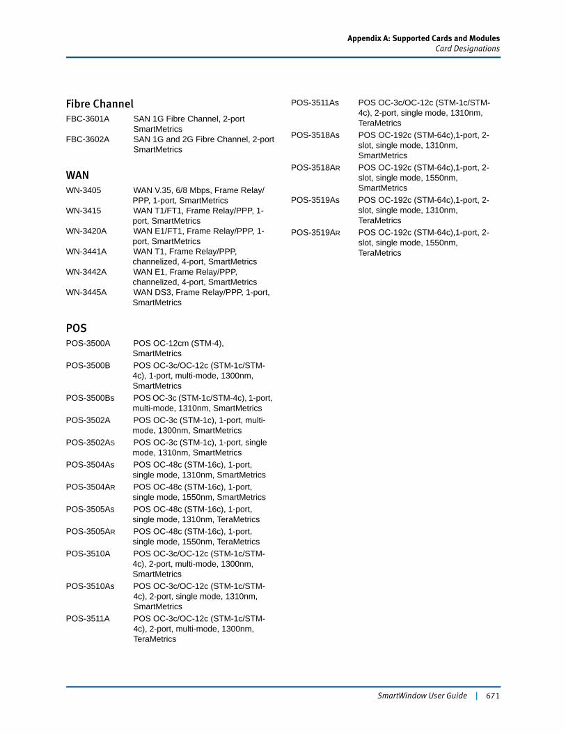
Appendix A: Supported Cards and ModulesCard Designations
SmartWindow User Guide | 671
Fibre ChannelFBC-3601A SAN 1G Fibre Channel, 2-port
SmartMetricsFBC-3602A SAN 1G and 2G Fibre Channel, 2-port
SmartMetrics
WANWN-3405 WAN V.35, 6/8 Mbps, Frame Relay/
PPP, 1-port, SmartMetricsWN-3415 WAN T1/FT1, Frame Relay/PPP, 1-
port, SmartMetricsWN-3420A WAN E1/FT1, Frame Relay/PPP, 1-
port, SmartMetricsWN-3441A WAN T1, Frame Relay/PPP,
channelized, 4-port, SmartMetricsWN-3442A WAN E1, Frame Relay/PPP,
channelized, 4-port, SmartMetricsWN-3445A WAN DS3, Frame Relay/PPP, 1-port,
SmartMetrics
POSPOS-3500A POS OC-12cm (STM-4),
SmartMetricsPOS-3500B POS OC-3c/OC-12c (STM-1c/STM-
4c), 1-port, multi-mode, 1300nm, SmartMetrics
POS-3500Bs POS OC-3c (STM-1c/STM-4c), 1-port, multi-mode, 1310nm, SmartMetrics
POS-3502A POS OC-3c (STM-1c), 1-port, multi-mode, 1300nm, SmartMetrics
POS-3502AS POS OC-3c (STM-1c), 1-port, single mode, 1310nm, SmartMetrics
POS-3504As POS OC-48c (STM-16c), 1-port, single mode, 1310nm, SmartMetrics
POS-3504AR POS OC-48c (STM-16c), 1-port, single mode, 1550nm, SmartMetrics
POS-3505As POS OC-48c (STM-16c), 1-port, single mode, 1310nm, TeraMetrics
POS-3505AR POS OC-48c (STM-16c), 1-port, single mode, 1550nm, TeraMetrics
POS-3510A POS OC-3c/OC-12c (STM-1c/STM-4c), 2-port, multi-mode, 1300nm, SmartMetrics
POS-3510As POS OC-3c/OC-12c (STM-1c/STM-4c), 2-port, single mode, 1310nm, SmartMetrics
POS-3511A POS OC-3c/OC-12c (STM-1c/STM-4c), 2-port, multi-mode, 1300nm, TeraMetrics
POS-3511As POS OC-3c/OC-12c (STM-1c/STM-4c), 2-port, single mode, 1310nm, TeraMetrics
POS-3518As POS OC-192c (STM-64c),1-port, 2-slot, single mode, 1310nm, SmartMetrics
POS-3518AR POS OC-192c (STM-64c),1-port, 2-slot, single mode, 1550nm, SmartMetrics
POS-3519As POS OC-192c (STM-64c),1-port, 2-slot, single mode, 1310nm, TeraMetrics
POS-3519AR POS OC-192c (STM-64c),1-port, 2-slot, single mode, 1550nm, TeraMetrics

672 | SmartWindow User Guide
Appendix B
Frame Rate Calculation
This appendix describes the method used to calculate the bandwidth utilization in the POS-35xx and LAN-3201B/C modules. Its intent is to provide readers with an understanding of how accurately these modules behave under certain load conditions. This description does not include the details of how the hardware operates.
In this appendix...
• About POS Wire Speed . . . . 674
• POS Frame Rate Calculation . . . . 675
• Gigabit Frame Rate Calculation . . . . 683
• Optimizing Utilization . . . . 690
SmartWindow User Guide | 673
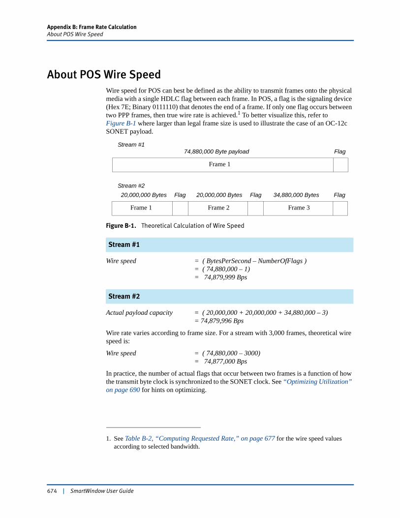
Appendix B: Frame Rate CalculationAbout POS Wire Speed
About POS Wire SpeedWire speed for POS can best be defined as the ability to transmit frames onto the physical media with a single HDLC flag between each frame. In POS, a flag is the signaling device (Hex 7E; Binary 0111110) that denotes the end of a frame. If only one flag occurs between two PPP frames, then true wire rate is achieved.1 To better visualize this, refer to Figure B-1 where larger than legal frame size is used to illustrate the case of an OC-12c SONET payload.
Figure B-1. Theoretical Calculation of Wire Speed
Stream #1
Wire speed = ( BytesPerSecond – NumberOfFlags )= ( 74,880,000 – 1)= 74,879,999 Bps
Stream #2
Actual payload capacity = ( 20,000,000 + 20,000,000 + 34,880,000 – 3) = 74,879,996 Bps
Wire rate varies according to frame size. For a stream with 3,000 frames, theoretical wire speed is:
Wire speed = ( 74,880,000 – 3000)= 74,877,000 Bps
In practice, the number of actual flags that occur between two frames is a function of how the transmit byte clock is synchronized to the SONET clock. See “Optimizing Utilization” on page 690 for hints on optimizing.
1. See Table B-2, “Computing Requested Rate,” on page 677 for the wire speed values according to selected bandwidth.
Stream #1Flag 74,880,000 Byte payload
Stream #2Flag34,880,000 Bytes20,000,000 Bytes20,000,000 Bytes FlagFlag
Frame 2
Frame 1
Frame 1 Frame 3
674 | SmartWindow User Guide

Appendix B: Frame Rate CalculationPOS Frame Rate Calculation
POS Frame Rate CalculationThe POS-35xx modules operate at two speeds: OC-3c and OC-12c. Each speed has been described independently for clarity. The OC-3c speed is 155.52 Mbps, and the OC-12c speed is 622.08 Mbps.
POS OC-12 Payload Capacity Calculation
The OC-12c SONET framing structure consists of 1,080 bytes: nine rows of 120 octets each. Forty of these octets are allocated to SONET overhead carrying SONET physical layer and error information. The OC-12c bit rate is 622.08 Mbps. Thus, the available payload capacity is:
Available payload capacity = ( ( 1040 / 1080 ) * 622.08 Mbps )= 599.04 Mbps= 74.88 Mbps
The actual payload capacity is then calculated from the available payload capacity by factoring in the tolerance of the clock carrying the SONET data. The worst case tolerance allowed by the SONET specification occurs with stratum-4 clock, with a minimum accuracy of 32 ppm. The actual payload capacity range that uses this value is shown here:
Max. actual payload capacity = ( 1 + 0.000032 ) * 74.88 Mbps= 74.88239616 Mbps
Min. actual payload capacity = ( 1 – 0.000032 ) * 74.88 Mbps= 74.87760384 Mbps
POS OC-3c Payload Capacity Calculation
The OC-3c payload capacity values are calculated here. The OC-3c bit rate is 155.52 Mbps. The available payload capacity is shown here:
Available payload capacity = [( 1040 / 1080 ) * 155.52 Mbps ]= 149.76 Mbps = 18.72 Mbps
The range of actual payload capacity values is shown here:
Max. actual payload capacity = ( 1 + 0.000032 ) * 18.72 Mbps= 18.72059904 Mbps
Min. actual payload capacity = ( 1 – 0.000032 ) * 18.72 Mbps= 18.71940096 Mbps
SmartWindow User Guide | 675
Appendix B: Frame Rate CalculationPOS Frame Rate Calculation
Payload Capacity Utilization
The payload capacity utilization is calculated on how frequently frames are generated: the higher the frame rate, the higher the payload capacity utilization. The maximum frame rate is achieved with the minimum interframe gap. In SONET, the minimum gap allowed is 1 byte. Thus, the maximum payload capacity utilization (measured in bytes per second) for a given frame size is:
Max. payload capacity utilization (Bps) = (max. frame rate) * [frame size + 1 (inter-frame gap) + CRC1]
Conversely, the frame rate can be calculated from the payload capacity utilization as follows:
(Max. frame rate) = Max. payload capacity utilization (Bps) / [frame size + 1 (inter-frame gap) + CRC]
Note: This calculation does not account for octet stuffing performed by the HDLC protocol layer. Octet stuffing is data dependent and the worst-case scenario may almost double the number of bytes sent, thereby reducing the capacity by half.
Capacity Utilization by Streams
In the POS-35xx modules, the frames are generated by individual streams. Each stream has its own frame generation definition and each stream utilizes part of the total payload capacity available. So, capacity utilization by any stream is:
Stream capacity utilization (Bps) = (stream frame rate) * (stream frame size + 1 [inter-frame gap) + CRC]
and
Aggregate stream capacity utilization = sum of individual stream capacity utilization
Even though streams are independent of each other, the stream capacity utilization of one stream may affect the stream capacity utilization of another stream, especially if the frames rates are different.
1. 2-byte or 4-byte CRC, depending on frame type
676 | SmartWindow User Guide
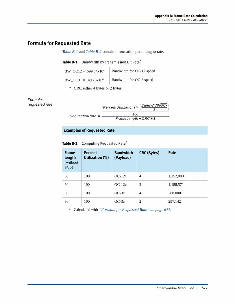
Appendix B: Frame Rate CalculationPOS Frame Rate Calculation
Formula for Requested Rate
Table B-1 and Table B-2 contain information pertaining to rate.
Formula: requested rate
Examples of Requested Rate
Table B-1. Bandwidth by Transmission Bit Rate*
* CRC either 4 bytes or 2 bytes
BW_OC12 = 599.04x10⁶ Bandwidth for OC-12 speed
BW_OC3 = 149.76x10⁶ Bandwidth for OC-3 speed
Table B-2. Computing Requested Rate*
* Calculated with “Formula for Requested Rate” on page 677.
Frame length(without FCS)
Percent Utilization (%)
Bandwidth (Payload)
CRC (Bytes) Rate
60 100 OC-12c 4 1,152,000
60 100 OC-12c 2 1,188,571
60 100 OC-3c 4 288,000
60 100 OC-3c 2 297,142
RequestedRate
PercentUtilization( ) BandWidthOCx8
---------------------------------------------⎝ ⎠⎛ ⎞×
100---------------------------------------------------------------------------------------
FrameLength CRC 1+ +---------------------------------------------------------------------------------------------------------------------=
SmartWindow User Guide | 677
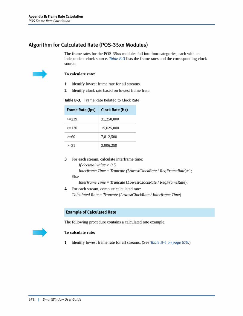
Appendix B: Frame Rate CalculationPOS Frame Rate Calculation
Algorithm for Calculated Rate (POS-35xx Modules)
The frame rates for the POS-35xx modules fall into four categories, each with an independent clock source. Table B-3 lists the frame rates and the corresponding clock source.
To calculate rate:
1 Identify lowest frame rate for all streams.2 Identify clock rate based on lowest frame frate.
3 For each stream, calculate interframe time:If decimal value > 0.5Interframe Time = Truncate (LowestClockRate / ReqFrameRate)+1;
ElseInterframe Time = Truncate (LowestClockRate / ReqFrameRate);
4 For each stream, compute calculated rate:Calculated Rate = Truncate (LowestClockRate / Interframe Time)
Example of Calculated Rate
The following procedure contains a calculated rate example.
To calculate rate:
1 Identify lowest frame rate for all streams. (See Table B-4 on page 679.)
Table B-3. Frame Rate Related to Clock Rate
Frame Rate (fps) Clock Rate (Hz)
>=239 31,250,000
>=120 15,625,000
>=60 7,812,500
>=31 3,906,250
678 | SmartWindow User Guide
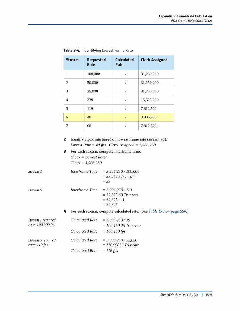
Appendix B: Frame Rate CalculationPOS Frame Rate Calculation
2 Identify clock rate based on lowest frame rate (stream #6).Lowest Rate = 40 fps Clock Assigned = 3,906,250
3 For each stream, compute interframe time.Clock = Lowest Rate;Clock = 3,906,250
Stream 1 Interframe Time = 3,906,250 / 100,000= 39.0625 Truncate= 39
Stream 5 Interframe Time = 3,906,250 / 119= 32,825.63 Truncate= 32,825 + 1= 32,826
4 For each stream, compute calculated rate. (See Table B-5 on page 680.)
Stream 1 required rate: 100,000 fps
Calculated Rate = 3,906,250 / 39= 100,160.25 Truncate
Calculated Rate = 100,160 fps
Stream 5 required rate: 119 fps
Calculated Rate = 3,906,250 / 32,826= 118.99865 Truncate
Calculated Rate = 118 fps
Table B-4. Identifying Lowest Frame Rate
Stream Requested Rate
Calculated Rate
Clock Assigned
1 100,000 / 31,250,000
2 50,000 / 31,250,000
3 25,000 / 31,250,000
4 239 / 15,625,000
5 119 / 7,812,500
6 40 / 3,906,250
7 60 / 7,812,500
SmartWindow User Guide | 679
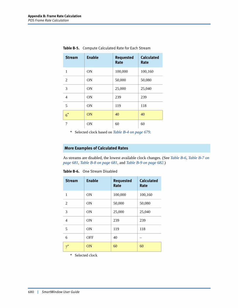
Appendix B: Frame Rate CalculationPOS Frame Rate Calculation
More Examples of Calculated Rates
As streams are disabled, the lowest available clock changes. (See Table B-6, Table B-7 on page 681, Table B-8 on page 681, and Table B-9 on page 682.)
Table B-5. Compute Calculated Rate for Each Stream
Stream Enable Requested Rate
Calculated Rate
1 ON 100,000 100,160
2 ON 50,000 50,080
3 ON 25,000 25,040
4 ON 239 239
5 ON 119 118
6*
* Selected clock based on Table B-4 on page 679.
ON 40 40
7 ON 60 60
Table B-6. One Stream Disabled
Stream Enable Requested Rate
Calculated Rate
1 ON 100,000 100,160
2 ON 50,000 50,080
3 ON 25,000 25,040
4 ON 239 239
5 ON 119 118
6 OFF 40 –
7*
* Selected clock
ON 60 60
680 | SmartWindow User Guide
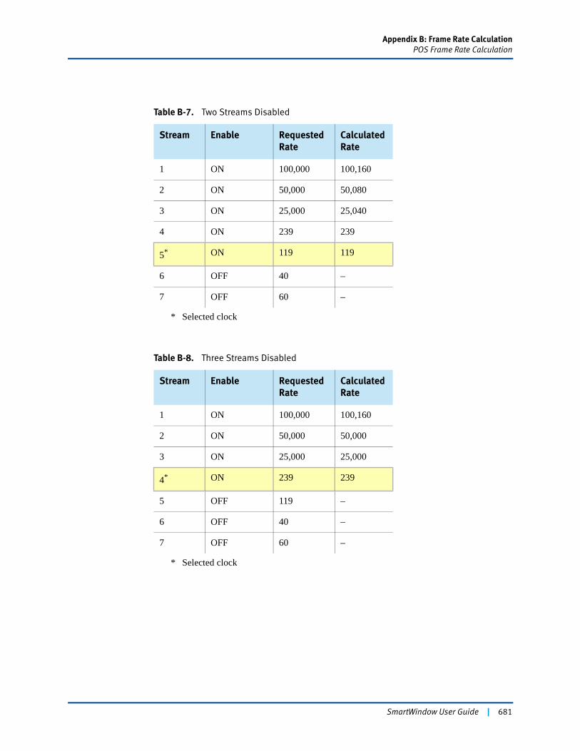
Appendix B: Frame Rate CalculationPOS Frame Rate Calculation
Table B-7. Two Streams Disabled
Stream Enable Requested Rate
Calculated Rate
1 ON 100,000 100,160
2 ON 50,000 50,080
3 ON 25,000 25,040
4 ON 239 239
5*
* Selected clock
ON 119 119
6 OFF 40 –
7 OFF 60 –
Table B-8. Three Streams Disabled
Stream Enable Requested Rate
Calculated Rate
1 ON 100,000 100,160
2 ON 50,000 50,000
3 ON 25,000 25,000
4*
* Selected clock
ON 239 239
5 OFF 119 –
6 OFF 40 –
7 OFF 60 –
SmartWindow User Guide | 681
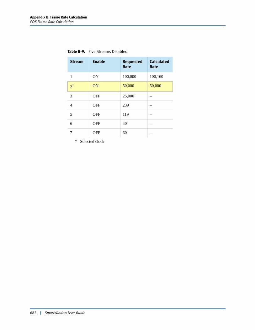
Appendix B: Frame Rate CalculationPOS Frame Rate Calculation
Table B-9. Five Streams Disabled
Stream Enable Requested Rate
Calculated Rate
1 ON 100,000 100,160
2*
* Selected clock
ON 50,000 50,000
3 OFF 25,000 –
4 OFF 239 –
5 OFF 119 –
6 OFF 40 –
7 OFF 60 –
682 | SmartWindow User Guide
Appendix B: Frame Rate CalculationGigabit Frame Rate Calculation
Gigabit Frame Rate CalculationThe LAN-320x modules operate at 1000 Mbps.
Payload Capacity Utilization
The payload capacity utilization is calculated on how frequently frames are generated. In other words, the higher the frame rate, the higher the payload capacity utilization. The maximum frame rate is achieved with the minimum interframe gap. In SmartMetrics gigabit, the minimum gap allowed is 12 bytes and the preamble minimum is 8 bytes.
The maximum payload capacity utilization (measured in bytes per second for a given frame size) is:
Max. payload capacity utilization (Bps) = (max. frame rate) * [frame size + 12 (inter-frame gap) + 8 (minimum preamble) + 4 (CRC)]
Conversely, the frame rate can be calculated from the payload capacity utilization as follows:
(Max. frame rate) = max. payload capacity utilization (Bps) / [frame size + 12 (inter-frame gap) + 8 (minimum preamble) + 4 (CRC)]
Capacity Utilization by Streams
In the LAN-320x modules, the frames are generated by individual streams. Each stream has its own frame generation definition and each stream utilizes part of the total payload capacity available. So, capacity utilization by any stream is:
Stream capacity utilization (Bps) = (stream frame rate) * (frame size + 12 [interframe gap) + 8 (minimum preamble) + 4 (CRC)]
and
Aggregate stream capacity utilization = sum of individual stream capacity utilization
Even though streams are independent of each other, the stream capacity utilization of one stream may affect the stream capacity utilization of another stream, especially if the frames rates are different.
The frame rates for the LAN-320x modules fall into four categories, each with an independent clock source. Table B-11 on page 685 lists the frame rates and the corresponding clock source.
Formula for Requested Rate
This is the formula for requested rate:
SmartWindow User Guide | 683
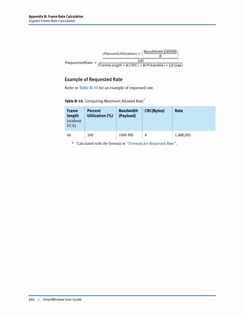
Appendix B: Frame Rate CalculationGigabit Frame Rate Calculation
Example of Requested Rate
Refer to Table B-10 for an example of requested rate.
Table B-10. Computing Maximum Allowed Rate*
* Calculated with the formula in “Formula for Requested Rate”.
Frame length(without FCS)
Percent Utilization (%)
Bandwidth (Payload)
CRC(Bytes) Rate
60 100 1000 Mb 4 1,488,095
RequestedRate
PercentUtilization( ) BandWidth1000Mb8
------------------------------------------------------⎝ ⎠⎛ ⎞×
100----------------------------------------------------------------------------------------------
FrameLength 4 CRC( ) 8 Preamble( ) 12 Gap( )+ + +---------------------------------------------------------------------------------------------------------------------------------------------=
684 | SmartWindow User Guide
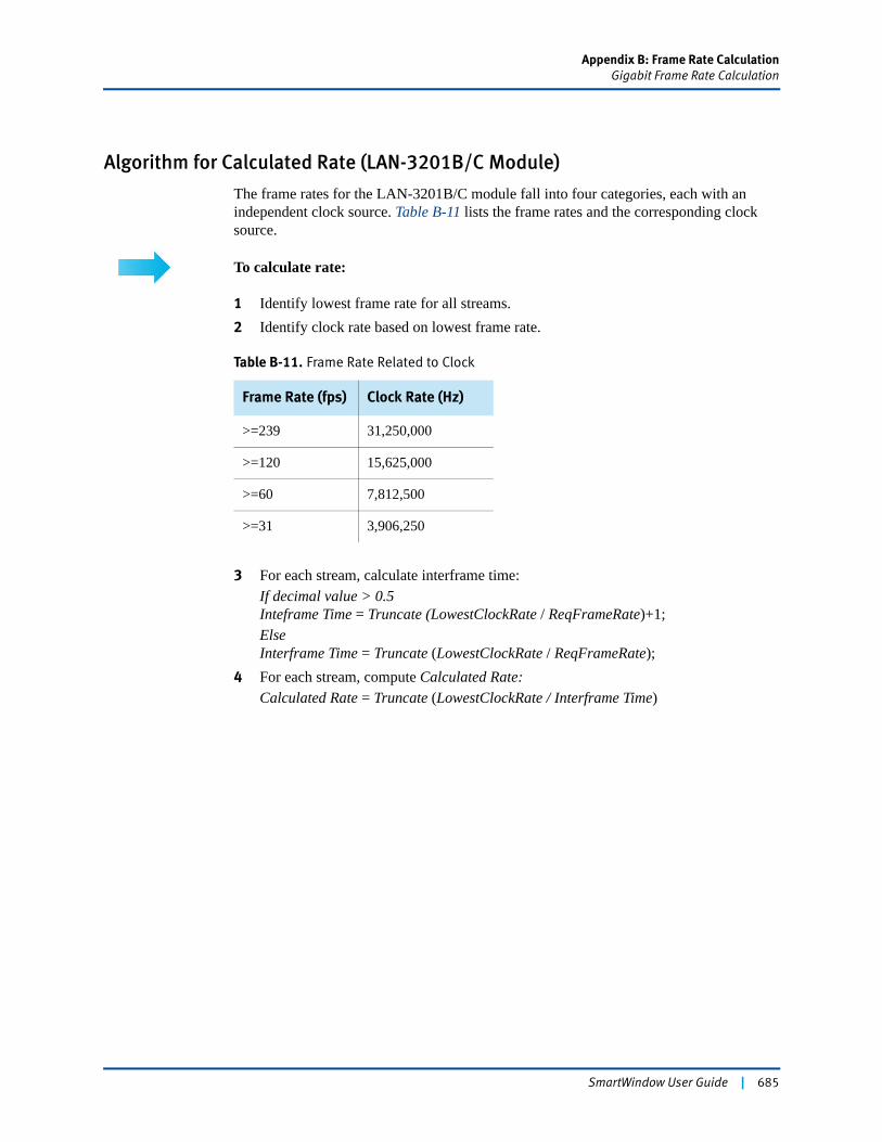
Appendix B: Frame Rate CalculationGigabit Frame Rate Calculation
Algorithm for Calculated Rate (LAN-3201B/C Module)
The frame rates for the LAN-3201B/C module fall into four categories, each with an independent clock source. Table B-11 lists the frame rates and the corresponding clock source.
To calculate rate:
1 Identify lowest frame rate for all streams.2 Identify clock rate based on lowest frame rate.
3 For each stream, calculate interframe time:If decimal value > 0.5Inteframe Time = Truncate (LowestClockRate / ReqFrameRate)+1;ElseInterframe Time = Truncate (LowestClockRate / ReqFrameRate);
4 For each stream, compute Calculated Rate:Calculated Rate = Truncate (LowestClockRate / Interframe Time)
Table B-11. Frame Rate Related to Clock
Frame Rate (fps) Clock Rate (Hz)
>=239 31,250,000
>=120 15,625,000
>=60 7,812,500
>=31 3,906,250
SmartWindow User Guide | 685
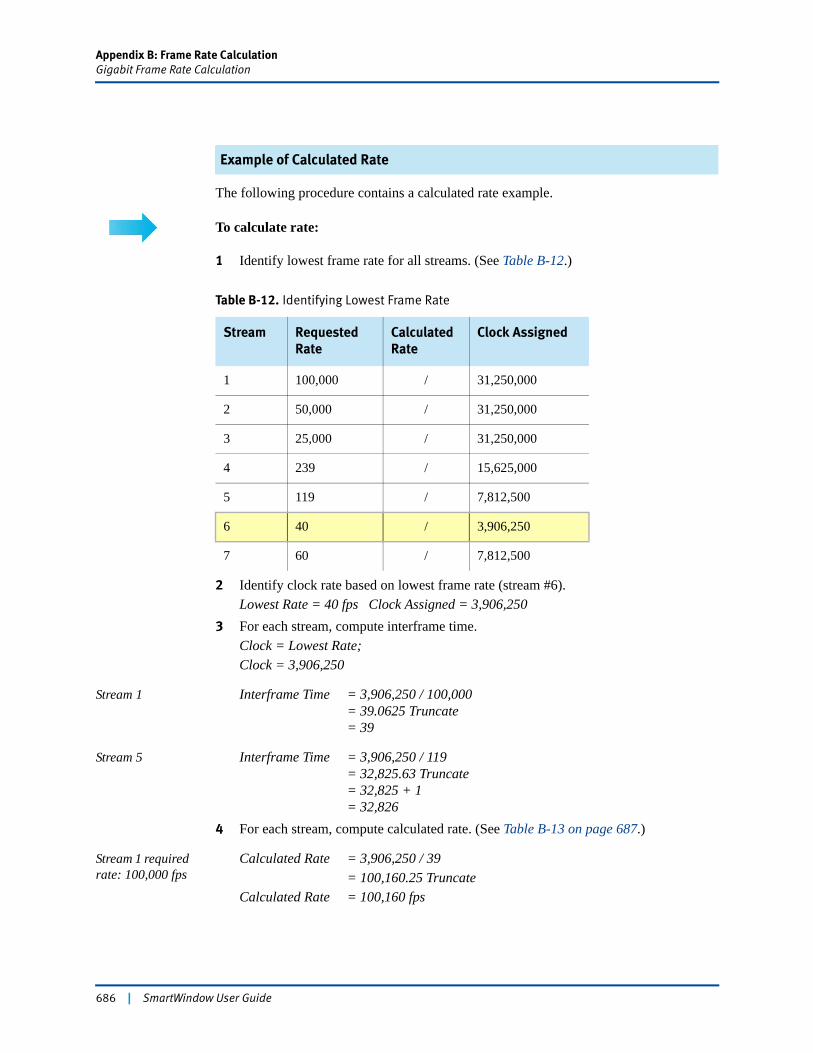
Appendix B: Frame Rate CalculationGigabit Frame Rate Calculation
Example of Calculated Rate
The following procedure contains a calculated rate example.
To calculate rate:
1 Identify lowest frame rate for all streams. (See Table B-12.)
2 Identify clock rate based on lowest frame rate (stream #6).Lowest Rate = 40 fps Clock Assigned = 3,906,250
3 For each stream, compute interframe time.Clock = Lowest Rate;Clock = 3,906,250
Stream 1 Interframe Time = 3,906,250 / 100,000= 39.0625 Truncate= 39
Stream 5 Interframe Time = 3,906,250 / 119= 32,825.63 Truncate= 32,825 + 1= 32,826
4 For each stream, compute calculated rate. (See Table B-13 on page 687.)
Stream 1 required rate: 100,000 fps
Calculated Rate = 3,906,250 / 39= 100,160.25 Truncate
Calculated Rate = 100,160 fps
Table B-12. Identifying Lowest Frame Rate
Stream Requested Rate
Calculated Rate
Clock Assigned
1 100,000 / 31,250,000
2 50,000 / 31,250,000
3 25,000 / 31,250,000
4 239 / 15,625,000
5 119 / 7,812,500
6 40 / 3,906,250
7 60 / 7,812,500
686 | SmartWindow User Guide
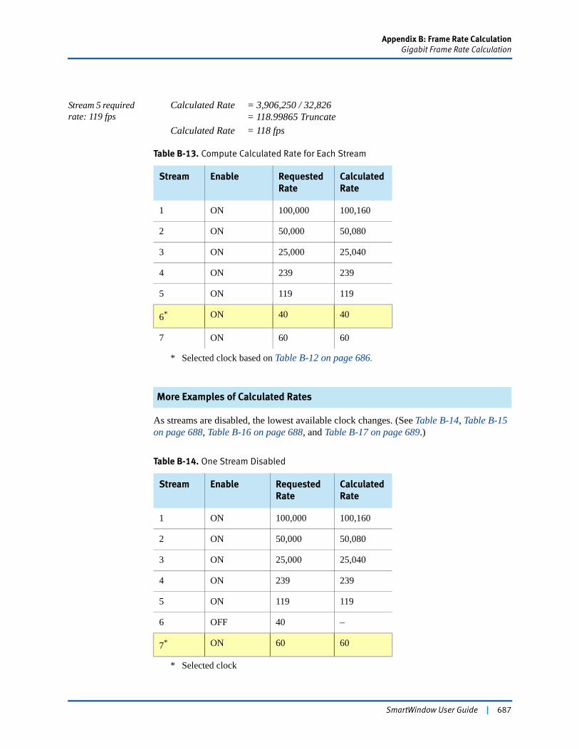
Appendix B: Frame Rate CalculationGigabit Frame Rate Calculation
Stream 5 required rate: 119 fps
Calculated Rate = 3,906,250 / 32,826= 118.99865 Truncate
Calculated Rate = 118 fps
More Examples of Calculated Rates
As streams are disabled, the lowest available clock changes. (See Table B-14, Table B-15 on page 688, Table B-16 on page 688, and Table B-17 on page 689.)
Table B-13. Compute Calculated Rate for Each Stream
Stream Enable Requested Rate
Calculated Rate
1 ON 100,000 100,160
2 ON 50,000 50,080
3 ON 25,000 25,040
4 ON 239 239
5 ON 119 119
6*
* Selected clock based on Table B-12 on page 686.
ON 40 40
7 ON 60 60
Table B-14. One Stream Disabled
Stream Enable Requested Rate
Calculated Rate
1 ON 100,000 100,160
2 ON 50,000 50,080
3 ON 25,000 25,040
4 ON 239 239
5 ON 119 119
6 OFF 40 –
7*
* Selected clock
ON 60 60
SmartWindow User Guide | 687

Appendix B: Frame Rate CalculationGigabit Frame Rate Calculation
Table B-15. Two Streams Disabled
Stream Enable Requested Rate
Calculated Rate
1 ON 100,000 100,160
2 ON 50,000 50,080
3 ON 25,000 25,040
4 ON 239 239
5*
* Selected clock
ON 119 119
6 OFF 40 –
7 OFF 60 –
Table B-16. Three Streams Disabled
Stream Enable Requested Rate
Calculated Rate
1 ON 100,000 100,160
2 ON 50,000 50,000
3 ON 25,000 25,000
4*
* Selected clock
ON 239 239
5 OFF 119 –
6 OFF 40 –
7 OFF 60 –
688 | SmartWindow User Guide
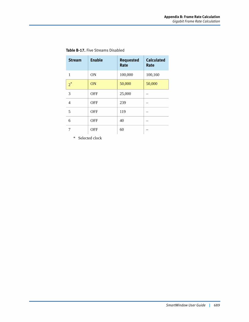
Appendix B: Frame Rate CalculationGigabit Frame Rate Calculation
Table B-17. Five Streams Disabled
Stream Enable Requested Rate
Calculated Rate
1 ON 100,000 100,160
2*
* Selected clock
ON 50,000 50,000
3 OFF 25,000 –
4 OFF 239 –
5 OFF 119 –
6 OFF 40 –
7 OFF 60 –
SmartWindow User Guide | 689
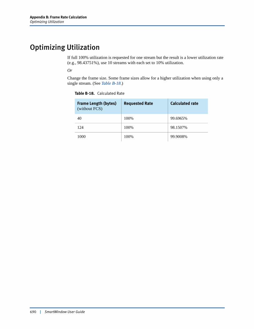
Appendix B: Frame Rate CalculationOptimizing Utilization
Optimizing UtilizationIf full 100% utilization is requested for one stream but the result is a lower utilization rate (e.g., 98.43751%), use 10 streams with each set to 10% utilization.
Or
Change the frame size. Some frame sizes allow for a higher utilization when using only a single stream. (See Table B-18.)
Table B-18. Calculated Rate
Frame Length (bytes) (without FCS)
Requested Rate Calculated rate
40 100% 99.6965%
124 100% 98.1507%
1000 100% 99.9008%
690 | SmartWindow User Guide
Appendix C
Managing the ET-1000 Controller
The ET-1000 controller was a precursor to the SmartBits 1000 and SmartBits 2000 chassis. A few configuration features of the ET-1000 controller that may be useful under certain circumstances were dropped from the standard Ethernet menus. Using specified Ethernet SmartCards, these features can still be accessed with configuration adjustments made through the SmartWindow ET-1000 menu.
Note: SmartWindow 6.50 was the last version to support the ET-1000 controller.
In this chapter...
• SmartCards that Support ET-1000 Functions . . . . 692
• When to Use ET-1000 Functions . . . . 692
• Configuring SmartCards for Use with ET-1000 Controller . . . . 693
• Accessing ET-1000 Functions . . . . 695
SmartWindow User Guide | 691

Appendix C: Managing the ET-1000 ControllerSmartCards that Support ET-1000 Functions
SmartCards that Support ET-1000 FunctionsOnly the following SmartCards support ET-1000 functions:
• SE-6205/SC-6305/ST-6405/6410 10 Mbps Ethernet SmartCards
• ST-6410 10 Mbps Full Duplex Ethernet SmartCard.
Other SmartCards, including the TokenRing and the 100 Mbps Ethernet SmartCards, do not support ET-1000 functions.
When to Use ET-1000 FunctionsThe ET-1000 controller supports some functions for 10 Mbps Ethernet that are not provided by the SmartWindow user interface. These functions include:
• Advanced collision generation capabilities
• Frame capture
• Preamble control and measurement.
Note: The SmartWindow ET-1000 EtherWindows menu can be used to configure the above tasks. See “Accessing ET-1000 Functions” on page 695.
692 | SmartWindow User Guide
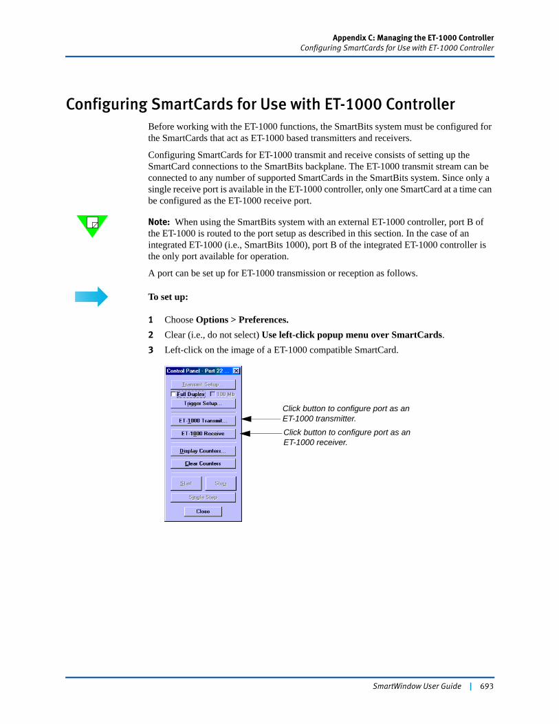
Appendix C: Managing the ET-1000 ControllerConfiguring SmartCards for Use with ET-1000 Controller
Configuring SmartCards for Use with ET-1000 ControllerBefore working with the ET-1000 functions, the SmartBits system must be configured for the SmartCards that act as ET-1000 based transmitters and receivers.
Configuring SmartCards for ET-1000 transmit and receive consists of setting up the SmartCard connections to the SmartBits backplane. The ET-1000 transmit stream can be connected to any number of supported SmartCards in the SmartBits system. Since only a single receive port is available in the ET-1000 controller, only one SmartCard at a time can be configured as the ET-1000 receive port.
Note: When using the SmartBits system with an external ET-1000 controller, port B of the ET-1000 is routed to the port setup as described in this section. In the case of an integrated ET-1000 (i.e., SmartBits 1000), port B of the integrated ET-1000 controller is the only port available for operation.
A port can be set up for ET-1000 transmission or reception as follows.
To set up:
1 Choose Options > Preferences.2 Clear (i.e., do not select) Use left-click popup menu over SmartCards.3 Left-click on the image of a ET-1000 compatible SmartCard.
Click button to configure port as anET-1000 transmitter.
Click button to configure port as anET-1000 receiver.
SmartWindow User Guide | 693
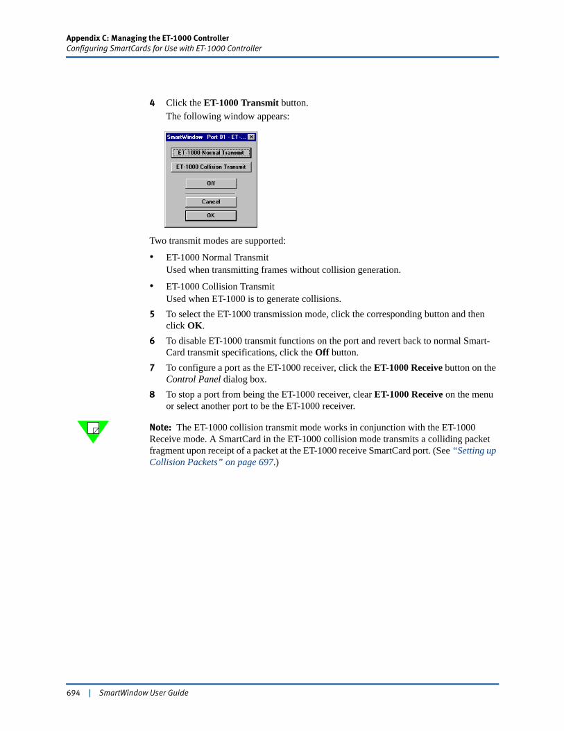
Appendix C: Managing the ET-1000 ControllerConfiguring SmartCards for Use with ET-1000 Controller
4 Click the ET-1000 Transmit button.The following window appears:
Two transmit modes are supported:
• ET-1000 Normal TransmitUsed when transmitting frames without collision generation.
• ET-1000 Collision TransmitUsed when ET-1000 is to generate collisions.
5 To select the ET-1000 transmission mode, click the corresponding button and then click OK.
6 To disable ET-1000 transmit functions on the port and revert back to normal Smart-Card transmit specifications, click the Off button.
7 To configure a port as the ET-1000 receiver, click the ET-1000 Receive button on the Control Panel dialog box.
8 To stop a port from being the ET-1000 receiver, clear ET-1000 Receive on the menu or select another port to be the ET-1000 receiver.
Note: The ET-1000 collision transmit mode works in conjunction with the ET-1000 Receive mode. A SmartCard in the ET-1000 collision mode transmits a colliding packet fragment upon receipt of a packet at the ET-1000 receive SmartCard port. (See “Setting up Collision Packets” on page 697.)
694 | SmartWindow User Guide
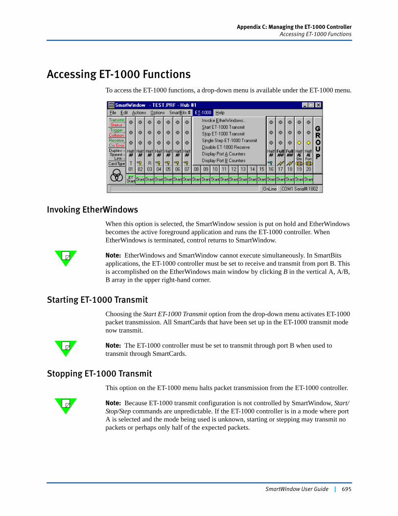
Appendix C: Managing the ET-1000 ControllerAccessing ET-1000 Functions
Accessing ET-1000 FunctionsTo access the ET-1000 functions, a drop-down menu is available under the ET-1000 menu.
Invoking EtherWindows
When this option is selected, the SmartWindow session is put on hold and EtherWindows becomes the active foreground application and runs the ET-1000 controller. When EtherWindows is terminated, control returns to SmartWindow.
Note: EtherWindows and SmartWindow cannot execute simultaneously. In SmartBits applications, the ET-1000 controller must be set to receive and transmit from port B. This is accomplished on the EtherWindows main window by clicking B in the vertical A, A/B, B array in the upper right-hand corner.
Starting ET-1000 Transmit
Choosing the Start ET-1000 Transmit option from the drop-down menu activates ET-1000 packet transmission. All SmartCards that have been set up in the ET-1000 transmit mode now transmit.
Note: The ET-1000 controller must be set to transmit through port B when used to transmit through SmartCards.
Stopping ET-1000 Transmit
This option on the ET-1000 menu halts packet transmission from the ET-1000 controller.
Note: Because ET-1000 transmit configuration is not controlled by SmartWindow, Start/Stop/Step commands are unpredictable. If the ET-1000 controller is in a mode where port A is selected and the mode being used is unknown, starting or stepping may transmit no packets or perhaps only half of the expected packets.
SmartWindow User Guide | 695
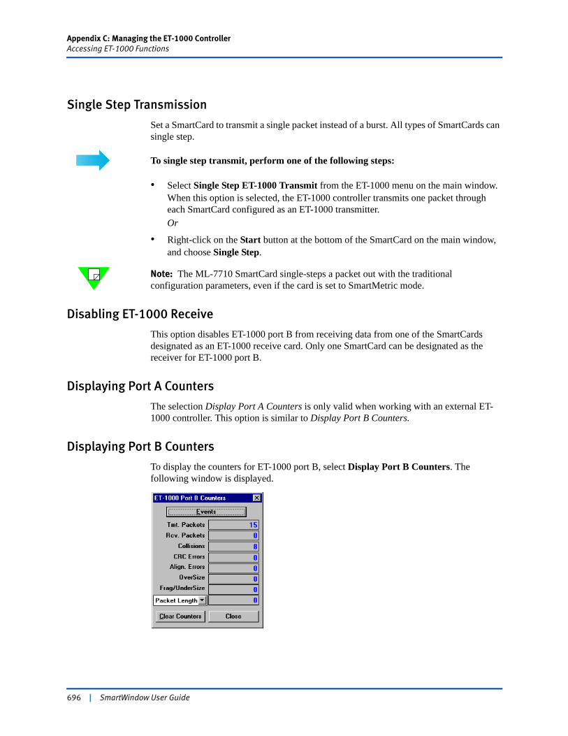
Appendix C: Managing the ET-1000 ControllerAccessing ET-1000 Functions
Single Step Transmission
Set a SmartCard to transmit a single packet instead of a burst. All types of SmartCards can single step.
To single step transmit, perform one of the following steps:
• Select Single Step ET-1000 Transmit from the ET-1000 menu on the main window. When this option is selected, the ET-1000 controller transmits one packet through each SmartCard configured as an ET-1000 transmitter.Or
• Right-click on the Start button at the bottom of the SmartCard on the main window, and choose Single Step.
Note: The ML-7710 SmartCard single-steps a packet out with the traditional configuration parameters, even if the card is set to SmartMetric mode.
Disabling ET-1000 Receive
This option disables ET-1000 port B from receiving data from one of the SmartCards designated as an ET-1000 receive card. Only one SmartCard can be designated as the receiver for ET-1000 port B.
Displaying Port A Counters
The selection Display Port A Counters is only valid when working with an external ET-1000 controller. This option is similar to Display Port B Counters.
Displaying Port B Counters
To display the counters for ET-1000 port B, select Display Port B Counters. The following window is displayed.
696 | SmartWindow User Guide
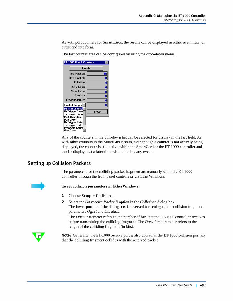
Appendix C: Managing the ET-1000 ControllerAccessing ET-1000 Functions
As with port counters for SmartCards, the results can be displayed in either event, rate, or event and rate form.
The last counter area can be configured by using the drop-down menu.
Any of the counters in the pull-down list can be selected for display in the last field. As with other counters in the SmartBits system, even though a counter is not actively being displayed, the counter is still active within the SmartCard or the ET-1000 controller and can be displayed at a later time without losing any events.
Setting up Collision Packets
The parameters for the colliding packet fragment are manually set in the ET-1000 controller through the front panel controls or via EtherWindows.
To set collision parameters in EtherWindows:
1 Choose Setup > Collisions.2 Select the On receive Packet B option in the Collisions dialog box.
The lower portion of the dialog box is reserved for setting up the collision fragment parameters Offset and Duration.The Offset parameter refers to the number of bits that the ET-1000 controller receives before transmitting the colliding fragment. The Duration parameter refers to the length of the colliding fragment (in bits).
Note: Generally, the ET-1000 receive port is also chosen as the ET-1000 collision port, so that the colliding fragment collides with the received packet.
SmartWindow User Guide | 697
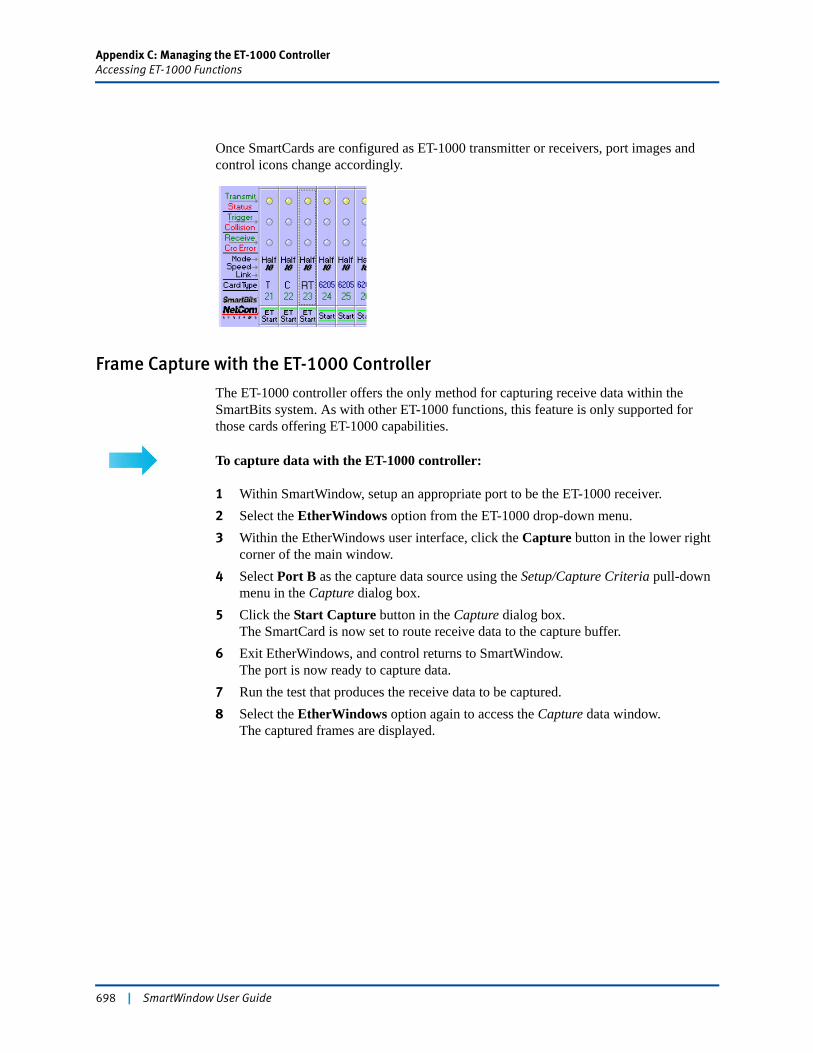
Appendix C: Managing the ET-1000 ControllerAccessing ET-1000 Functions
Once SmartCards are configured as ET-1000 transmitter or receivers, port images and control icons change accordingly.
Frame Capture with the ET-1000 Controller
The ET-1000 controller offers the only method for capturing receive data within the SmartBits system. As with other ET-1000 functions, this feature is only supported for those cards offering ET-1000 capabilities.
To capture data with the ET-1000 controller:
1 Within SmartWindow, setup an appropriate port to be the ET-1000 receiver.2 Select the EtherWindows option from the ET-1000 drop-down menu.3 Within the EtherWindows user interface, click the Capture button in the lower right
corner of the main window.4 Select Port B as the capture data source using the Setup/Capture Criteria pull-down
menu in the Capture dialog box.5 Click the Start Capture button in the Capture dialog box.
The SmartCard is now set to route receive data to the capture buffer. 6 Exit EtherWindows, and control returns to SmartWindow.
The port is now ready to capture data.7 Run the test that produces the receive data to be captured. 8 Select the EtherWindows option again to access the Capture data window.
The captured frames are displayed.
698 | SmartWindow User Guide
Appendix D
Data Integrity on TeraMetrics
The data integrity function allows the SmartBits modules to send and receive a frame with a marker (called the data integrity marker) as an additional means of verification that the user payload was received correctly. This feature is used to determine if packet corruption occurred internal to a router where the packet is not protected with a Layer 2 CRC. The data integrity function requires that the configuration be set up in a specific manner to operate properly. This appendix provides configuration information for the SmartBits modules that are used as well as answers to frequently asked questions regarding this function.
Module InformationThe data integrity function applies only to the following SmartMetrics and TeraMetrics modules:
• LAN-3300A 10/100/1000Base-T Ethernet Copper, 2-port, SmartMetrics
• LAN-3301A 10/100/1000Base-T Ethernet Copper, 2-port, TeraMetrics
• LAN-3302A 10/100Base-T Ethernet Copper, 2-port, TeraMetrics
• LAN-3310A 1000Base-X Ethernet, GBIC, 2-port, SmartMetrics
• LAN-3311A 1000Base-X Ethernet, GBIC, 2-port, TeraMetrics
• POS-3504As POS OC-48c, 1-port, single mode, 1310nm, SmartMetrics
• POS-3504AR POS OC-48c, 1-port, single mode, 1550nm, SmartMetrics
• POS-3505As POS OC-48c, 1-port, single mode, 1310nm, TeraMetrics
• POS-3504AR POS OC-48c, 1-port, single mode, 1550nm, TeraMetrics
• POS-3510A POS OC-3c/OC-12c, 2-port, multi-mode, 1300nm, SmartMetrics
• POS-3510As POS OC-3c/OC-12c, 2-port, single mode, 1310nm, SmartMetrics
• POS-3511A POS OC-3c/OC-12c, 2-port, multi-mode, 1300nm, TeraMetrics
• POS-3511As POS OC-3c/OC-12c, 2-port, single mode, 1310nm, TeraMetrics
• POS-3518As POS OC-192c, 1-port, 2-slot, single mode, 1310nm, SmartMetrics
• POS-3518AR POS OC-192c, 1-port, 2-slot, single mode, 1550nm, SmartMetrics
• POS-3519As POS OC-192c, 1-port, 2-slot, single mode, 1310nm, TeraMetrics
SmartWindow User Guide | 699
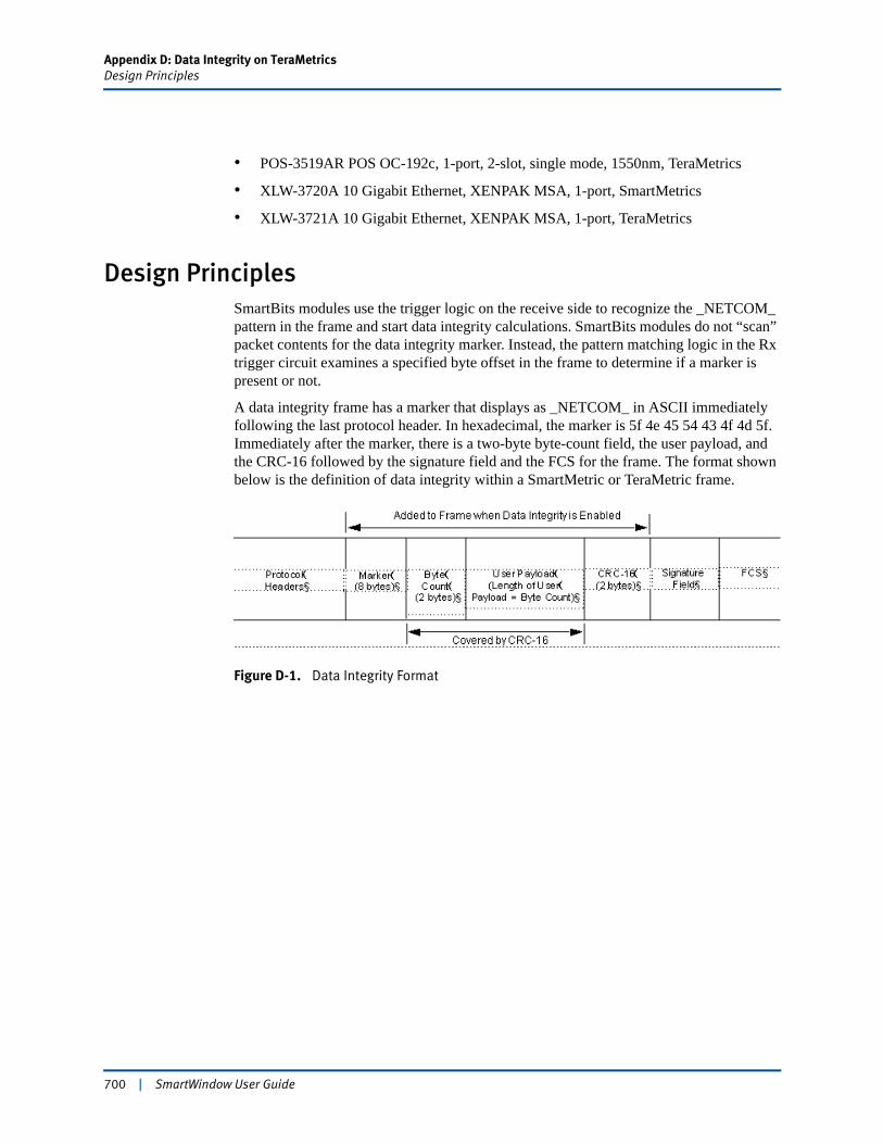
Appendix D: Data Integrity on TeraMetricsDesign Principles
• POS-3519AR POS OC-192c, 1-port, 2-slot, single mode, 1550nm, TeraMetrics
• XLW-3720A 10 Gigabit Ethernet, XENPAK MSA, 1-port, SmartMetrics
• XLW-3721A 10 Gigabit Ethernet, XENPAK MSA, 1-port, TeraMetrics
Design PrinciplesSmartBits modules use the trigger logic on the receive side to recognize the _NETCOM_ pattern in the frame and start data integrity calculations. SmartBits modules do not “scan” packet contents for the data integrity marker. Instead, the pattern matching logic in the Rx trigger circuit examines a specified byte offset in the frame to determine if a marker is present or not.
A data integrity frame has a marker that displays as _NETCOM_ in ASCII immediately following the last protocol header. In hexadecimal, the marker is 5f 4e 45 54 43 4f 4d 5f. Immediately after the marker, there is a two-byte byte-count field, the user payload, and the CRC-16 followed by the signature field and the FCS for the frame. The format shown below is the definition of data integrity within a SmartMetric or TeraMetric frame.
Figure D-1. Data Integrity Format
700 | SmartWindow User Guide
Appendix D: Data Integrity on TeraMetricsTransmit Configuration
Transmit ConfigurationTo transmit data integrity frames for a stream on a TeraMetrics module, select Enable Data Integrity via SmartWindow or SmartLib.
Important: • When streams are configured in SmartWindow 7.50, they are set to transmit the data integrity marker by default.
• Data integrity can be enabled or disabled in the Streams Configuration window or you can select a stream, choose the edit function, and select the Data Integrity checkbox.
• Only frames that contain the signature field can have the data integrity function enabled. In other words, data integrity works only when the module is in SmartMetrics mode and the signature field is enabled.
• The modules statically calculate TCP checksums during stream configuration, prior to real-time generation of packets. Data integrity calculations are performed in real-time. Therefore, the data integrity feature cannot be used with TCP protocol. Data integrity does work with IP and UDP protocol.
Note: TeraMetrics modules do not support error injection in this feature. However, it is possible to send erred data integrity frames using the custom protocol by imitating a faulty data integrity frame.
When data integrity is enabled, it modifies the modules as follows:• Places the start of data integrity immediately after the protocol headers. This start
position can vary, depending on the specifics of the protocol stack in the packet.• Includes the marker, length, and CRC-16 fields.
SmartWindow User Guide | 701
Appendix D: Data Integrity on TeraMetricsReceive Configuration
Receive ConfigurationTo count or measure data integrity frames on a TeraMetrics module, first set a receive trigger on the data integrity marker.
To set a receive trigger on the data integrity marker using SmartWindow or SmartLib, set trigger 1 to match the last six bytes of the eight-byte data integrity marker. The byte offset for the trigger must be set to point to the E in _NETCOM_ and the trigger value should be set to ETCOM_ (hexadecimal 45 54 43 4f 4d 5f).
For example, when receiving in an Ethernet frame with an IP header only, the offset should be set to byte 36, corresponding to the E (ASCII 45).
Important: • There are two receive triggers: Rx trigger 1 and Rx trigger 2.
• Receive trigger 1 must be correctly configured to recognize the data integrity marker.
• When receive trigger 1 is used for data integrity marker detection, the other trigger must not interfere. In SmartWindow receive trigger setup, select the Only trigger 1, ignore trigger 2 option.
• A receive trigger offset is a static value. It can only point to a fixed number of bytes beyond the beginning of a packet. This is a “per port” parameter. The byte offset of the receive trigger needs to be based on the received frame type, not the transmitted frame type.
Counter Interpretation and Results
When the transmit and receive settings are set according to this document, the data integrity counter shows data integrity errors received on the port. Frames with data integrity errors are counted in the frame receive statistics, both counters and histograms.
Note: The byte pointer is used to locate the length field. Any trigger MATCH causes the data integrity logic to check the packet. Therefore, data integrity errors can be indicated any time the Rx trigger is asserted.
702 | SmartWindow User Guide
Appendix D: Data Integrity on TeraMetricsCapture Information
Capture InformationCapture displays data integrity errors only if you capture on data integrity errors. Capture status shows “D” only if capture filtering is enabled on data integrity errors.
To capture on data integrity errors:
1 In SmartWindow, select Capture.2 Set the Capture Events field value to Data Integrity Errors.
If this field value is not selected, the frames are listed as triggered frames, and no mention of data integrity occurs.
Note: When trigger frames are received, the Rx engine automatically checks data integrity on the frame. Marking these frames in the Capture window as data integrity errors works only when the trigger is set up to point to the data integrity marker. However, if the Capture Events field value is Data Integrity Errors and the trigger is pointing to somewhere else in the frame, a trigger match causes all of the frames in the capture buffer to show as if they have data integrity errors, even when they do not have such errors.
More Details on Rx FunctionalityThe trigger/match logic is implemented as described previously in this appendix. However, it conveys only MATCH or NO_MATCH information. If there is a MATCH, it provides a byte pointer where the match occurred to the receive engine.
The receive engine performs the following actions for data integrity:
• If MATCH = TRUE, then the LENGTH field is used to re-calculate the CRC-16 and compare to the CRC-16 in the packet.
• If it is a signature frame and the CRC-16 is errored, then the data integrity ERROR counter is incremented.
• If it is not a signature frame, then the data integrity errors are ignored.
Note: The byte pointer is used to locate the length field. Any MATCH causes the data integrity logic to check the packet. Therefore, data integrity errors can be indicated any time the Rx trigger is asserted.
SmartWindow User Guide | 703
Appendix D: Data Integrity on TeraMetricsRx Trigger Configuration and Resource
Rx Trigger Configuration and ResourceIn regards to Rx trigger configuration and resource:
• There is no always on detection of the data integrity marker. The Rx trigger must be configured to see the marker.
• The Rx trigger resource is consumed when running data integrity tests.
704 | SmartWindow User Guide
Appendix E
ESD Requirements
Spirent Communications manufactures and sells products that require industry standard precautions to protect against damage from electrostatic discharge (ESD). This document explains the proper process for handling and storing electrostatic discharge sensitive (ESDS) devices, assemblies, and equipment.
The requirements presented in this document comply with the EIA Standard, ANSI/ESD S20.20-1999: Development of an Electrostatic Discharge Control Program, and apply to anyone who handles equipment that is sensitive to electrostatic discharge. Such equipment includes, but it not limited to:
• All electronic assemblies manufactured by Spirent Communications
• Discrete and integrated circuit semiconductors
• Hybrid microcircuits
• Thin film passive devices
• Memory modules
! Caution: Failure to comply with the requirements explained in this document poses risks to the performance of ESDS devices, as well as to your investment in the equipment.
General Equipment Handling
Whenever you handle a piece of ESDS equipment, you must be properly grounded to avoid harming the equipment. Also, when transporting the equipment, it must be packaged properly. Follow the requirements below to help ensure equipment protection.
• Wrist straps must be worn by any person handling the equipment to provide normal grounding.
• The use of foot straps is encouraged to supplement normal grounding. If foot straps are used exclusively, two straps (one on each foot) should be used. Note that foot straps are only applicable in environments that use ESD flooring and/or floor mats.
• Hold ESDS equipment by the edges only; do not touch the electronic components or gold connectors.
• When transporting equipment between ESD protected work areas, the equipment must be contained in ESD protective packaging. Equipment that is received in ESD protective packaging must be opened either by a person who is properly grounded or at an ESD protected workstation.
SmartWindow User Guide | 705

Appendix E: ESD Requirements
• Any racks or carts used for the temporary storage or transport of ESDS equipment must be grounded either by drag chains or through direct connection to earth ground. Loose parts that are not protected by ESD-safe packaging must not be transported on carts.
Workstation Preparation
The ideal setup for working with ESDS equipment is a workstation designed specifically for that purpose. Figure E-1 illustrates an ESD protected workstation. Please follow the requirements listed below to prepare a proper ESD protected workstation.
• The ESD Ground must be the equipment earth ground. Equipment earth ground is the electrical ground (green) wire at the receptacles.
• An ESD protected workstation consists of a table or workbench with a static dissipative surface or mat that is connected to earth ground. A resistor in the grounding wire is optional, providing that surface resistance to ground is ≥ 105 to ≤ 109 Ω.
• The workstation must provide for the connection of a wrist strap. The wrist strap must contain a current limiting resistor with a value from ≥ 250K Ω to ≤ 10M Ω.
• ESD protective flooring or floor mats are required when floor-grounding devices (foot straps/footwear) are used or when it is necessary to move in between ESD protected workstations when handling ESDS equipment.
Figure E-1. ESD Protected Workstation
Note: The equipment needed for proper grounding is available in ESD service kits, such as the ESD Field Service Kit available from Spirent Communications (P/N 170-1800). Additional information on ESD can be found on the following website: http://www.esda.org/aboutesd.html
ESD protective surface or matOptional resistor
Wrist strap
ESD protective floor mat (optional)
706 | SmartWindow User Guide
Appendix F
Fiber Optic Cleaning Guidelines
Spirent Communications manufactures and sells products that contain fiber optic components, including fiber optic transmitters and receivers. These components are extremely susceptible to contamination by particles of dirt or dust, which can obstruct the optic path and cause performance degradation. To ensure optimum product performance, it is important that all optics and connector ferrules be kept clean.
This document presents guidelines for maintaining clean fiber optic components. Spirent Communications recommends that these guidelines be followed very closely.
! Caution: • Failure to comply with the guidelines explained in this document poses risks to the performance of fiber optic-based devices, as well as to your investment in the equipment.
• Whenever you handle a piece of equipment that contains fiber optic components, you must be properly grounded to avoid harming the equipment. See the Appendix in this document titled ESD Requirements for more details on ESD.
Cleaning Guidelines
To ensure the cleanliness of fiber optic components, follow the guidelines below:
• Use fiber patch cords (or connectors if you terminate your own fiber) only from a reputable supplier. Low-quality components can cause many hard-to-diagnose problems during an installation.
• Dust caps are typically installed on fiber optic components to ensure factory-clean optical devices. These protective caps should not be removed until the moment of connecting the fiber cable to the device. Ensure that the fiber is properly terminated, polished, and free of any dust or dirt. Also make sure that the location of installation is as free of dust and dirt as possible.
• Should it be necessary to disconnect the fiber device, reinstall the protective dust caps.
• If you suspect that the optics have been contaminated, alternate between blasting with clean, dry, compressed air and flushing with methanol to remove particles of dirt.
SmartWindow User Guide | 707

708 | SmartWindow User Guide
Index
Symbols*.msi 55*.prf 41, 55, 97
Numerics10Gbps Ethernet 3553D dialog 63802.3x flow control 380850nm ShortWave multi-mode fiber 380
AActions menu 59Address display format 171address format
for multicast traffic 115Admin menu 71Administrative control 72advertised speed, Gigabit setup 223aggregate line rate 480algorithm for calculated rate, POS 678, 685Alignment Errors Event Counter 140Allow bit level control of VFD1 and VFD2 64Allow MII/GMII Auto-Negotiate option 64allowing MII auto-negotiation for
SmartCards 245ANSI standards, supported 624applying joins or leaves to multicast streams 118ARP Exchange Times Test 304ARP requests at full-wire speed 244ARP responses 269ARP/Neighbor Discovery 66Asynchronous Transfer Mode 522ATM
Adaptation Layer 5 524Asynchronous Transfer Mode 522cell 524changing from hex to decimal 528Class of Service 542creating traffic descriptors 541latency measurements 553Line Interface Parameters option 526PPP tab 534protocol 107, 108registering signaling parameters 542security, PAP/CHAP 535stream connect failure codes 537
Traffic Setup window 62UNI signaling messages 62
Auto IP Flowbetween Layer 2 and Layer 3 227Custom frame type 229
auto negotiation, 10Gb Ethernet 356
Bbackground patterns 107, 477backing up configuration files 99Backoff Truncation Exponent 24, 70bandwidth
based on DS0 selection 468calculated, in PVC Setup pane 480reducing frame size 472
baud rate 43Bit Error Test 353bit-stuffing 481bucket intervals
SmartMetrics 16-bit tests 292burst 24Byte Counter 140
Ccable modems
as device of "host" SmartCard 208testing 203
cablingwith mutliple chassis 30
Calculated Values 570calculating frame rate 481capacity utilization by streams (Gigabit) 683capture 145, 477
common procedure 155Fibre Channel tests 665packets 148
Change SmartCard to 52changing from hex to decimal in ATM
readout 528changing MII registers 166Channel Setup pane 467chassis
multiple 81SmartBits 200 51SmartBits 600 53
CIR 501
SmartWindow User Guide | 709

Index
Cisco HDLCencapsulation 567, 585frame configuration 473
Class of Service (ATM) 542Clear Counters option 141collision generation 692, 694Collisions Event counter 139COM port 42configuration
channel parameters 478converting from SmartBits 200/2000 to
SmartBits 600/6000B 102copy/paste 56, 57default 464DS3 line parameters 477frame content 108frame relay switch 474LMI parameters 478overview 464physical connections 474PPP 467PVC 479SmartCard Network Interactions 108streams 480T1 line parameters 477trigger parameters 479
configuration filesbacking up 99creating 98file types 97saving 55
configuringa burst of 5000 packets for USB 206a group of cards 51an individual card 51frame content 108Gigabit router 228Gigabit streams 384groups of cards 84ILMI protocol 539LAN-3201B Gigabit Ethernet 381Layer 3 setup 238streams, POS 586triggers for a group of SmartCards 89
connecting to SmartBitsat startup 63, 66by Ethernet 42by serial 42setup 42, 44
connecting, ATM streams 529connection problems 44Connection Setup dialog 45controller firmware 6.50 95controller firmware 6.60 95controller serial number 18controlling groups of cards 88, 93converting SmartWindow configurations 102copy/paste
chassis configuration 57in capture spreadsheet 155port to chassis 58streams 472
counters 138, 483byte 139clearing 141collisions 139fragments 140over size packets 140
CRC Error Event counter 139creating
ATM traffic descriptors 541configuration file 98VLAN tags 225
customizingGigabit flows 388SmartWindow operation 62
customizing POS flows 591cut through devices 306cyclic ARPs 186cycling IP address hosts on a subnet 227
Ddata capture 488, 665
editing 488viewing 488, 665
data decode 167Data Integrity checkbox 390, 438data integrity on TeraMetrics 699Data Link Connection Identifier 453Data Link Connection Identifier (DLCI) 452
global (card-wide) assignments 480setting 501
data link type 467, 478frame relay 467PPP 467
DE (discard eligible) frames 484Default
Netmask option 64to SmartMetric mode After File/New
option 64default
chassis preference file 80configuration 464inter-ARP gap 244
default template MDIO file 67defining frame length for frame relay
streams 498, 513defining groups of SmartCards 86Diagnostic Options 561discard eligible frames 484disk space requirements (SmartWindow tests) 20,
47displaying counters 90downloading preference files to a SmartBits
chassis 100dribble 200
710 | SmartWindow User Guide
Index
DS0 selectionWN-3445A DS3 card 465
DS3 line parameters 477duplex mode, restore after File/Open 65duplicating streams 472dynamic ILMI registration 540
EEdit menu 56editing
frame content 157Hosts.sam file 83Smartbit.ini file 81
EIA leads 495ELANs 547Enable Laser option 562enabling auto negotiation 165E-Port 627equalization 350equipment handling
ESD service kits 706guidelines 700, 705preparing your workstation 706
error messages 29ESD requirements 705ESI 540establishing SVCs 538ET-1000 functions
accessing 695configuring SmartCards 693frame capture 698menu 691supported SmartCards 692
ET-1000 Transmit functions 695, 696Ethernet "framing" vs. USB "packeting" 206Ethernet SmartCards 138, 691, 692EtherWindows 692, 695, 697, 698
FF_Port 627Fast Ethernet/Gigabit options 64FBC Port Setup dialog 635Fibre Channel 623
capture 665defined 624Group Control 61standards 624
Field ChooserIGMP Management window 127
file conversion 102File menu 41, 55, 97File Update (WAN cards) 459firmware 2.00 285Firmware Revision information 18FL_Port 627flows (POS) 568, 578, 586fluctuations in receive frame rate 481format options for IPv6 addresses 68
Formula Bar 427formula for requested rate (POS) 677, 684FR/PPP header
Custom frames 499VFD1 (editing frames) 499
Frag/Under Size Packets Event Counter 140frame format, IP multicast 115Frame header length, with IPv6 streams 169frame rate
adjusting to fit bandwidth 470bit-stuffing 481estimating highest possible per stream 471fluctuations in received rate 481receive frame rate fluctuations 481
frame relaydata circuit-terminating equipment 492data link type 467line rate 505Line Rate option 494troubleshooting test results 506
frame relay switch 452as DCE 474characteristics 453
frame size, with IPv6 streams 175Frame Variation test 304full duplex 107, 108, 692
GGigabit
configuring streams 384Layer 3 Setup option 339, 383line parameters 326, 375, 382
glossary 625graphing results in Excel format 443Group Counters 141Group functions menu 85groups of SmartCards, configuring 84guidelines
(equipment handling) 700, 705
Hhardware handling and cleaning 15HDLC flag (hex 7E) 674HDLC frame configuration 473header, in IPv6 streams 173Help 462
context-sensitive (F1) Help 462using for detailed information 475
higher priority trafficGigabit QOS testing 230
histogramsdownload 20, 47precision 293
host name-to-address mapping 83Hosts.sam file, editing 83
IIEEE Draft P802.3ae 342
SmartWindow User Guide | 711

Index
IGMP 112Actions menu 60how to set up 112Leave request 114overview 114reserved addresses 115setting up on SmartBits 200/2000 Ethernet
cards 116setting up on SmartBits 600/6000B/6000C
Ethernet modules 120version 117, 519versions 114with VLAN tags 129
IGMP Management window 120ILMI 524Increase Frame Length option 361Initialize Ports after Connect option 63Initialize Ports after Connect/Reserve option 66Initialize Ports after File/Open or File/New
option 63, 66installation problems 29installing SmartWindow
from CD-ROM disk 29instances, multiple 81Insufficient Disk Space message 29Internet Assigned Numbers Authority
(IANA) 115Internet Group Management Protocol
(IGMP) 112Interpacket Gap values, USB 206Interruption of the Installation Process
message 29invalid COM Port 44IP address 242, 243
assignments 267for SmartWindow connection 45in Address Resolution Protocol 243in Layer 3 setup 242of streams 262, 270of streams, cards, DUTs 591
IP Flow pane 482IP flows, in Gigabit SmartMetrics 388IP multicast
frame format 115setting up on SmartBits 200/2000 Ethernet
cards 116setting up on SmartBits 600/6000B/6000C
Ethernet modules 120traffic 112WAN cards 514
IPv6 Display Formats option 68IPv6 streams
address display format 171frame header length 169header fields 173protocol and frame size 175stream count and frame header length 169test setup 169
Jjabber count 185Jitter Pattern Generation test 351Jumbo Frame mode 360Jumbo frames
legal frame sizes 185using Jabber Count to simulate 185
Jumbo frames, card support 184
LLAN-3710A 10GbE module
OAM patterns 445setting VFD3 358test setup example 355transmit table 364trigger mask 371
LANE MAC addresses 552LASI NRV 336Latency Distribution test 297latency measurements (ATM) 553Latency Over Time test 296Latency per VTE test 295, 297latency tests 306Launch Workshop 431launching SmartWindow 31Layer 2 and Layer 3
Auto IP Flow 227USB configuration 208
Layer 3ARP 60, 243card 243Frame Variation test 304Setup 155
Layer 3 Setup option 238, 242, 307Ping, ARP, and RIP 156
learning MAC addresses 271LEC 524LECS 524LED status lights 50left-click popup menu 64LES 524levels of service (POS) 589Line Interface Parameters option (ATM) 526line rate (frame relay) 505line utilization 480Link Management Interface (LMI) 474, 478Link Management Protocol 492LMI Setup pane 478Loopback Mode option 562
MMAC addresses
for ATM cards 552in ARP 243in SmartMetrics tests 236
Main window 50mapping a multicast IP address to an Ethernet
address 115mask
712 | SmartWindow User Guide

Index
in trigger setup 371master/slave control of data flow 223MBZ 574MDIO 339, 342
default template file 67equalization 350Loss of Signal 350pre-emphasis 350selecting on Options>Preferences dialog 67
memory requirements per stream 20, 47menu bar 459merging VTE configurations 101MII
registers 107, 108MII auto-negotiation, allowing 64, 67MII registers
changing 166printing 166reading and writing 165restore after File/Open 64Selected Register Data field 165Selected Register Description field 165shortcuts on port menu 163
ML-7710 SmartCardLayer 3 Test 306single-step transmission 696transmit packet event counter 138
modifying multiple instances 460modifying the TOS field using VFD3 227MPLS 575multicast
how to set up 112setting up on SmartBits 200/2000 Ethernet
cards 116setting up on SmartBits 600/6000B/6000C
Ethernet modules 120multicast Groups and VLANs 129multicast traffic 112Multicast Virtual Circuit (MVC) (frame
relay) 452multiple chassis
interconnet requirements 30multiple instances of SmartWindow 81multiple streams 20, 47, 62, 107, 136multi-user
capability 92ownership status 92refitting SmartBits 2000 chassis 95SmartBits 2000 firmware 95stack of SmartBits 2000 chassis 95
N*.vs 55N_Port 629naming connections 82network interactions 107, 108, 109network traffic 20, 47, 306null modem cable 44
OOAM pattern 445Observer data decoder 167obtaining source MAC Address 209OC-12c
SONET payload 674off-line configuration 79on-line configuration 80online Help 14OnLine/Offline indicator 45opening
configuration 101single instance of SmartWindow 78SmartWindow 78
optical assembly (OA) 320optimizing 16-bit Latency testing 289Options menu 62Over Size Packets Event counter 140oversize frames in Jumbo mode 184, 360overwriting FR/PPP header 499overwriting signature field 157, 159ownership status
indicator 53multi-user 92
Ppacket contents, decoding 167packet loss test
USB 204USB (Layer 2) 205
PAP/CHAPATM 535
physical connections 474Ping target 242Ping, ARP, and RIP
Layer 3 Setup option 156Point-to-Point Protocol (PPP) over ATM 532port counters 138
Ethernet SmartCards 138spreadsheet capabilities 131, 415
port numberingSmartBits 600/6000B/6000C 54
Port to Chassis copy/paste 58Ports Explorer 428ports for SmartBits connection 45POS
automatically renegotiating PPP link 580, 592calculating OC-12 payload capacity 675calculating OC-3c payload capacity 675capacity utilization of streams 676Cisco HDLC encapsulation 567configuring streams 586customizing flows 591cycling IP addresses (incrementing) 592diagnostic options 561Ecapsulation tab 583editing IP addresses 577, 590Enable Laser option 562
SmartWindow User Guide | 713

Index
flows 578frame contents 559frame sizes 559handshaking (LCP) 566, 585incrementing IP addresses 591levels of service 589line parameters 582Loopback Mode option 562MPLS 575payload bytes 559PPP encapsulation 563, 583QOS capability of a router 568, 586scrambler 583Send Ping Packet 565, 585Sequence and Latency test 595setting up the DUT 580, 593smartbit.ini file 144SmartCounters 594SONET Alarm Generation 561SONET Payload Envelope Scrambling 333,
561SONET/SDH parameters 561, 583streams and flows 568, 586wire speed 674
PPPCisco protocol 585data link type 467encapsulation (POS) 563, 583scrambling the SONET payload 583Setup Parameters dialog 535
PPP Setup pane 467PPP Statistics pane 484PPP Status pane 485precision
SmartMetrics 16-bit tests 290pre-emphasis 350Preferences dialog
Options menu 62preparing DUT for VLAN testing 216printing
MII registers 166procedure for capture 155PVC 524
ATM 522frame relay 452
PVC Setup pane 480PVC Statistics pane 484
QQoS
for Gigabit router tests 228value in Gigabit Smartmetrics tests 386
RRaw Packet Tags test 303reading and writing MII Registers 165Receive Trigger Setup
LAN-3710A 10GbE module 371reconfiguring IP address 46
refitting SmartBits 2000 chassis for multi-user 95registering ILMI 538registers
MDIO 350Remote Host 45renegotiating PPP link (POS) 580, 592repeating Custom frame in another stream or
card 161Reply to all ARP requests option 238, 242requirements
electrostatic discharge 705requirements, PC 28requirements, RAM 28reserved addresses
in mutlicast 115reserving cards 93, 96Restore duplex setting after File/Open 65restore MII Control register 245Restore MII Control Register 0 after File/
Open 64Restore MII Register 0, 4, and 9 after Connect/
Reserve option 67Restore MII Register 0, 4, and 9 after File/Open
or File/New option 67RS-232 cable 44running tests 483Rx Alarm Control Register 336
Ssaving
configuration 101configuration file in SmartWindow 6.50 or
later 97configuration settings 101
SC-6x05 10Mb Ethernet option 64Schedule Mode (in Fibre Channel tests) 639scrambling the SONET payload 583Selector byte 540Sequence and Latency test 297Sequence Tracking test 297serial number (controller) 18setting histogram precision 293
in Latency tests 294setting up
Gigabit line parameters 326, 375, 382SmartCounters Window 134SSCOP/UNI 540WAN Port 494
signaling parameters (ATM) 542signature field
overwriting 157, 159simultaneous starting in SmartMetrics tests 143,
286smartbit.ini 61, 81, 142
naming connections 82POS 144Preferences options 142Protocol Editor options 144Recent Hosts options 144
714 | SmartWindow User Guide

Index
Serial Numbers options 143, 144WAN Card Settings options 144
SmartBits 6000Bmulti-user 92
SmartBits chassis 20, 44, 45, 56, 58connecting to 44connection on startup 63, 66Connection Setup dialog 45Ethernet port 45image in SmartWindow 50IP address 62port selection with multiple 57reconfiguring IP address 47SmartBits IP Configuration dialog 71
SmartBits signature field 151SmartBits Users
from Admin Menu 72SmartCard
merge 101open 101save 101supported 20
SmartCard groupcontrolling 87defining 85displaying counters 90transmit setup 89trigger setup 89
SmartCounters 131, 487menu 136menus 135operation 131timed save 133toolbar 136
SmartFabricsupported ANSI standards 624test suite 623
SmartMetrics 107, 10816-bit tests, precision 290Ethernet Cards option (Options menu) 64, 67results 307Test window 288testing 284, 478versus Traditional testing 200
SmartWindowmultiple instances 81number of simultaneous instances 78online Help 14opening 78start-up 31Windows 95/98 31
SmartWindow interfaceSmartBits 200 51SmartBits 200/2000 50SmartBits 600/6000B/6000C 53WN-3445A 457
SONET Alarm Generation 561SONET Payload Envelope Scrambling 333, 561
SONET/SDH parameters 561, 583Sort By Name box 421source MAC address of cable modems 208Spirent Communications
company address 16technical support 16
ST-6x05 10Mb Ethernet option 65starting SmartWindow 31static ILMI assignment 540Storage Area Networks 624store and forward devices 306stream connect failure codes (ATM) 537Stream Setup pane 473, 481Stream Statistics 429streams
configuring for Cisco HDLC frames 473how to duplicate 472order and repetition 364setting up 468
streams and flows (POS) 568, 586Streams Explorer 430streams per SmartCards 47stutter count 364SVC
ATM 522defined 524frame relay 452
synchronizing transmit byte clock to SONET clock 674
TT1 line parameters 477TCP Port (in Connection Setup dialog) 45technical support 16Test window 307testing
10Gbps Ethernet 355ATM devices 521cable modems 203Fibre Channel/SANs 623frame relay devices 449Gigabit routers 315LAN-3201B Gigabit Ethernet 375Layer 3 gigabit devices 380POS routers 557QoS for Gigabit Routers 228SmartMetrics 235TOS 161traditional LANs 199VLAN switch for flooding and leakage 215VLAN with GX-1420B 214xDSL 599XLW-3721A XENPAK MSA TeraMetrics
module 318Tests Menu 70tiling SmartCounters 135timed save 133Timed Save option 424
SmartWindow User Guide | 715
Index
timing, multiple chassis 78toolbar 459topology (in Fibre Channel) 635Traditional testing
versus SmartMetrics 200traffic breakpoint (frame relay) 504traffic controls, burst 24Transmit Mode options in WAN tests 510transmit table 364Trigger Setup dialog 89, 107, 155Trigger Setup pane 479triggers 145troubleshooting frame relay test results 506trunk ports vs. access ports, in VLANs 215Tx Alarm Control Register 336Type of Service (TOS) 573types of tests 109
Uupdating SmartBits configuration 100USB 203
"packeting" vs. Ethernet "framing" 206configuration at Layer 2 and Layer 3 208full line rate 207packet loss test 204querying and changing MAC addresses 213
Use Left-Click popup menu over SmartCards option 64
user guidehardware handling and cleaning 15
VV.35 Winchester cable 493VC Mux PPP encapsulation 534VCC 524VFD 107, 108, 243, 303VFD1 and VFD2
bit level control 65VFD3
guidelines for LAN-3710A 358View list 460View menu 74virtual circuit connection 452, 453Virtual Flow Cyclic ARPs 186virtual flow cyclic ARPs
module support 186virtual flows
cyclic ARPs 186virtual front panel 50virtual port numbering 54Virtual Transmit Engine 284VLAN
multicast groups 129tagging 380trunk ports vs. access ports 215
VLAN stacking (QnQ) TX side support features 130, 365
VLAN tags
Jumbo Frame mode 185, 360
WWAN
clear channel transmission 490overwriting FR/PPP header 499SmartCounters 504statistics 503transmit modes 510transmit setup 497
Workshop Selector 432Workshop Toolbar 427workstation preparation 706World Wide Name (WWN) 649
XXAUI 329
Bit Error Test 353IEEE Draft P802.3ae 342Jitter Pattern Generation test 351MDIO registers 350technology overview 342test bench (typical) 346XAUI Extender Unit 345
XENPAK MSA moduletest setup 318
XLW-3721A TeraMetrics module 318features and functions 318
716 | SmartWindow User Guide