
SmartSTACK Token Ring Switches...
126
SmartSTACK Token Ring Switches SPECTRUM Enterprise Manager Device Management Supports Management Module SM-CSI1095
Transcript of SmartSTACK Token Ring Switches...

SmartSTACK Token RingSwitches
SPECTRUM Enterprise ManagerDevice Management
Supports Management Module SM-CSI1095

D o c u m e n t F a m i l y Page 2 T i t l e
NoticeAprisma Management Technologies, Inc. (Aprisma), reserves the right to makechanges in specifications and other information contained in this document withoutprior notice. The reader should in all cases consult Aprisma to determine whetherany such changes have been made.
The hardware, firmware, or software described in this manual is subject to changewithout notice.
IN NO EVENT SHALL APRISMA, ITS EMPLOYEES, OFFICERS, DIRECTORS,AGENTS, OR AFFILIATES BE LIABLE FOR ANY INCIDENTAL, INDIRECT,SPECIAL, OR CONSEQUENTIAL DAMAGES WHATSOEVER (INCLUDING BUTNOT LIMITED TO LOST PROFITS) ARISING OUT OF OR RELATED TO THISMANUAL OR THE INFORMATION CONTAINED IN IT, EVEN IF APRISMA HASBEEN ADVISED OF, KNOWN, OR SHOULD HAVE KNOWN, THE POSSIBILITYOF SUCH DAMAGES.
Copyright © June 2000 by Aprisma Management Technologies. All rights reserved.
Printed in the United States of America.
Order Number: 9033574-01
Aprisma Management Technologies, Inc.121 Technology DriveDurham NH 03824
SPECTRUM, the SPECTRUM IMT/VNM logo, DCM, IMT, and VNM are registeredtrademarks, and SpectroGRAPH , SpectroSERVER , Inductive ModelingTechnology , Device Communications Manager , and Virtual Network Machineare trademarks of Cabletron Systems, Inc.
Ethernet is a trademark of Xerox Corporation.
Virus DisclaimerAprisma makes no representations or warranties to the effect that the LicensedSoftware is virus-free.
Aprisma has tested its software with current virus checking technologies. However,because no anti-virus system is 100% reliable, we strongly caution you to writeprotect and then verify that the Licensed Software, prior to installing it, is virus-freewith an anti-virus system in which you have confidence.
Restricted Rights Notice(Applicable to licenses to the United States Government only.)
1. Use, duplication, or disclosure by the Government is subject to restrictions asset forth in subparagraph (c) (1) (ii) of the Rights in Technical Data andComputer Software clause at DFARS 252.227-7013.
Aprisma Management Technologies, Inc., 121 Technology Drive NH 03824
2. (a) This computer software is submitted with restricted rights. It may not beused, reproduced, or disclosed by the Government except as provided inparagraph (b) of this Notice or as otherwise expressly stated in the contract.
(b) This computer software may be:
(1) Used or copied for use in or with the computer or computers for whichit was acquired, including use at any Government installation to whichsuch computer or computers may be transferred;
(2) Used or copied for use in a backup computer if any computer for whichit was acquired is inoperative;
(3) Reproduced for safekeeping (archives) or backup purposes;
(4) Modified, adapted, or combined with other computer software, providedthat the modified, combined, or adapted portions of the derivativesoftware incorporating restricted computer software are made subjectto the same restricted rights;
(5) Disclosed to and reproduced for use by support service contractors inaccordance with subparagraphs (b) (1) through (4) of this clause,provided the Government makes such disclosure or reproductionsubject to these restricted rights; and
(6) Used or copied for use in or transferred to a replacement computer.
(c) Notwithstanding the foregoing, if this computer software is publishedcopyrighted computer software, it is licensed to the Government, withoutdisclosure prohibitions, with the minimum rights set forth in paragraph (b) ofthis clause.
(d) Any other rights or limitations regarding the use, duplication, or disclosureof this computer software are to be expressly stated in, or incorporated in,the contract.
(e) This Notice shall be marked on any reproduction of this computer software, inwhole or in part.

S P E C T R U M E n t e r p r i s e M a n a g e r Page 3 SmartSTACK Token Ring Switches
ContentsINTRODUCTION 7
Purpose and Scope ........................................................7Required Reading ...........................................................7Supported Devices..........................................................8The SPECTRUM Model ..................................................8
TASKS 11
Administrative Status (configure/examine) .........11Alarms, Traps (configure) ...................................11Analyze Packet and Error Counts (examine) .....11Application Being Viewed (modify) .....................11Bandwidth (check) ..............................................11Chassis Information (examine)...........................11Configure the Device (configure)........................11Configure Switch Ports (configure).....................11Device Performance (monitor) ...........................11Enable/Disable Ports (modify) ............................12Interface Mask and Address (modify).................12Model Information (examine)..............................12Model Redundancy (configure) ..........................12Monitoring Ports (monitor) ..................................12Performing a Download (modify) ........................12Port Configuration (examine/modify) ..................12Port Statistics (monitor) ......................................12Security (configure) ............................................12Setting Thresholds (examine/modify) .................12
Topology (check)................................................12
DEVICE VIEWS 13
Interface Device View ...................................................13Interface Icons...........................................................14
Interface Icon Subviews Menu...............................15Interface Detail View .................................................16Sub-Interfaces ...........................................................16Interface Status View ................................................16Interface Configuration View .....................................16Model Information View.............................................17Interface Address Translation Table .........................17Secondary Address Panel.........................................17Interface Threshold View...........................................17Switch Port Table Entry View ....................................17
Chassis Device View ....................................................18Module Icon...............................................................18
Module Labels .......................................................19Module Icon Subviews Menu .............................19Switch Module Table Entry.................................19
Port Labels.............................................................20Port Icon Subviews Menu...................................20
DEVICE TOPOLOGY VIEWS 22
Interface Device Topology View ...................................22Chassis Device Topology View.....................................23

C o n t e n t s C o n t e n t s
S P E C T R U M E n t e r p r i s e M a n a g e r Page 4 SmartSTACK Token Ring Switches
APPLICATION VIEWS 24
Application Icons ...........................................................25Supported Applications .................................................25
Cisco VTP Applications .............................................26Cisco VTP Management Domain View..................26
Add Domain Management Table Entry ..............27Cisco VTP VLAN Information View........................27Cisco VTP VLAN Editing View...............................28
VLAN Editing Control Table ...............................28VLAN Edit Buffer Table ......................................29
Cisco Trunk Port Information View ........................30DTR Concentrator Application...................................32
Concentrator Relay Function View ........................32Spanning Tree Information View............................34
Spanning Tree Table..........................................35Static/Dynamic Filtering View ................................35
Dynamic MAC Table ..........................................36Dynamic Route Table .........................................36Static/Dynamic Table .........................................38Static MAC .........................................................38Static Route Table..............................................39
Port Mask Information View ...................................40STS16 Applications ...................................................41
Power Supply Information View .............................41ATM Uplink Application .............................................42
Permanent Virtual Connections View ....................42Add PVC Table Entry .........................................43
Traffic Profiles View ...............................................43Add Traffic Profiles Entry....................................45VAP Traffic Profile Mapping View ......................45
Add Mapping Table Entry .................................. 46VCC Status Information......................................... 46
Fast Ethernet Uplink Application............................... 49Fast Ethernet Uplink DS21143 View ..................... 49
High Speed Token Ring Uplink Application .............. 50HSTR ThunderLAN Diagnostics Table.................. 50
DTR Mac MIB Applications ....................................... 51dot5 Statistics Information ..................................... 51802.5 Information for Interface Number ................ 52
PERFORMANCE VIEWS 53
ATM Uplink Performance View .................................... 53VAP LANE and Outbound Performance View .......... 55
VAP Lane Statistics Table..................................... 55Outbound Statistics Table ..................................... 55
VAP LANE and Outbound Performance View - ATMDiagnostics Table .............................................. 55
Ctron ATM App............................................................. 56Cisco VTP Application Performance View ................... 56DTR Concentrator Application Performance View ....... 56Fast Ethernet Uplink Performance View ...................... 57
Virtual Port Statistics Table....................................... 57Fast Ethernet Virtual Port In Discards View.............. 58Fast Ethernet Virtual Port Out Discards View ........... 58
Gen Bridge App ............................................................ 58HSTR Uplink Performance View .................................. 59
HSTR Virtual Port Performance View ....................... 60MAC Mib Performance View ........................................ 60MIB-ll Performance View.............................................. 60Port Performance View ................................................ 60

C o n t e n t s C o n t e n t s
S P E C T R U M E n t e r p r i s e M a n a g e r Page 5 SmartSTACK Token Ring Switches
SNMP Agent Detail View...........................................61Switch Performance View .............................................62
Switch Port Performance View ..................................62
CONFIGURATION VIEWS 64
Interface Configuration View.........................................64ATM Uplink Configuration View ....................................65
Common VAP Configuration View.............................67Specific VAP Configuration....................................68MAC Address Connections ....................................71
Port Hardware Setup View ........................................72Message Logs View...............................................72LED Status Table...................................................73
STS16 Configuration View............................................73Redundancy and Model Reconfiguration Options .....74Interface Address Translation Table..........................75
Interface Configuration Table........................................75Fast Ethernet Uplink Configuration ...............................76
Fast Ethernet Port Configuration ...............................77Fast Ethernet Virtual Port Configuration Table..........79
Fast Ethernet Virtual Port Protocols Table.............81Fast Ethernet Virtual Port Novell Protocol Table 82NetBios Translational Bridging Table .................82SNA Translational Bridging Table ......................83Fast Ethernet Virtual Port Other Protocol Table .83Fast Ethernet Virtual Port SNA Protocol Table
(w/ SNAP)....................................................83Fast Ethernet Virtual Port SNA Protocol Table
(w/o SNAP)..................................................84Dual Home Address Table.....................................84
Port Mapping Information Table ............................ 84Port Mapping ..................................................... 84Virtual Port Mapping Table ................................ 85
Led Status Table....................................................... 85HSTR Uplink Configuration Table ................................ 86
HSTR Port Configuration Table ................................ 87Port Mapping Information ...................................... 89
Port Mapping ..................................................... 89Virtual Port Mapping .......................................... 89
HSTR Virtual Port Configuration Table ..................... 89Add Entry Virtual Port Entry .................................. 91LED Status Table .................................................. 91
Signaling Configuration View ....................................... 92SSCOP Configuration View ...................................... 93
STS16 Stack Configuration View ................................. 94Trap Receiver Information View................................ 96
Add Trap Receiver Table Entry View .................... 97Switch Stack Configuration View .............................. 97Switch Module Information View............................... 99Port Configuration View .......................................... 101
Probe/Crosslink Configuration View........................... 104Passive Probe Table............................................... 104Crosslink Table ....................................................... 105
TrCRF Configuration View ......................................... 105TrCRF Configuration Table..................................... 105
TrCRF Configuration Table Entry........................ 107TrBRF Configuration View.......................................... 107Filter Configuration View ............................................ 108
Class Filter Table .................................................... 109Protocol Filter Table................................................ 109

C o n t e n t s C o n t e n t s
S P E C T R U M E n t e r p r i s e M a n a g e r Page 6 SmartSTACK Token Ring Switches
Destination MAC Filter.............................................111Add Destination MAC Table Entry .......................112
Source MAC Filter ...................................................112Add Source MAC Table Entry..............................113
Duplicate/Trunk Configuration .................................114Duplicate Address................................................114Trunk Protocol Table............................................114
Switch Port Table Entry ..............................................115
MODEL INFORMATION VIEWS 119
INDEX 120

D e v i c e M a n a g e m e n t 7 S m a r t S T A C K T o k e n R i n g S w i t c h e s
IntroductionThis section introduces the SPECTRUM Device Management documentation for SmartSTACK Token Ringswitches.
This introduction to the Device Management documentation for SmartSTACK Token Ring switches contains the following information:
• Purpose and Scope• Required Reading• Supported Devices (Page 8)• The SPECTRUM Model (Page 8)
Purpose and ScopeUse this documentation as a guide for managing SmartSTACK Token Ring switches with the SPECTRUM management module SM-CSI1095. The documentation describes the icons, menus, and views that enable you to remotely monitor, configure, and troubleshoot SmartSTACK Token Ring switches through software models in your SPECTRUM database.
Only information specific to the supported management module is included under this documentation topic. For general information about device management using SPECTRUM and
for explanations of basic SPECTRUM functionality and navigation techniques, refer to the topics listed under Required Reading.
Required ReadingTo use this documentation effectively, you must be familiar with the information covered by the other SPECTRUM online documentation topics listed below.
• Getting Started with SPECTRUM for Operators
• Getting Started with SPECTRUM for Administrators
• How To Manage Your Network with SPECTRUM
• SPECTRUM Views• Software Release Notes• SPECTRUM Menus• SPECTRUM Icons• Management Module SRN

I n t r o d u c t i o n S u p p o r t e d D e v i c e s
D e v i c e M a n a g e m e n t 8 S m a r t S T A C K T o k e n R i n g S w i t c h e s
Supported DevicesThe SmartSTACK Token Ring Switch family (STS16-20xx) provides Token Ring Workgroups with backbone connectivity to ATM, High Speed Token Ring and Fast Ethernet via SmartSTACK Interface Modules (SSIMs). It complies with the IEEE 802.5r specification for Dedicated Token Ring (DTR). Its design is stackable, providing easy expansion and scalability. RMON management, Broadcast reduction and advanced filtering features increase network performance and ease backbone congestion in client-server networks. The SPECTRUM management module SM-CSI1095 currently allows you to model four types of SmartSTACK Token Ring switches as described below.
STS16-20RM. This switch has 20 ports (RJ-45), and two SSIM slots for supporting high speed uplinks to corporate backbones.
STS16-20R. This switch is similar to the aforementioned, but without the SSIM slots. It is designed to be stacked easily to the STS16-20RM via the stack interface on the rear of the switches to increase the port density. Up to 8 switches are supported per stack via a switch stacker unit.
STS16-20D. Designed for the desktop, this switch with 16 ports supporting one station per port, and four ports which can provide full network connectivity. This unit can be used to replace older shared hub ports while provid-ing increased performance and reliability. This unit can also be stacked to the work-group segmentation switches as well.
STS16-20FRM. For applications requiring fiber optic cabling connectivity, this switch supports 20 ports of Multimode fiber cabling via VF-45 connections, making fiber connec-tions as easy to use as RJ-45 UTP cable con-nections.
The SPECTRUM ModelSPECTRUM uses a single device model type, STS16, for modeling any of the supported SmartSTACK Token Ring switches. STS16 models are represented in SpectroGRAPH views by Device icons.
Figure 1 (Page 9) shows the Device icon varies slightly depending on the kind of view it appears in.

I n t r o d u c t i o n T h e S P E C T R U M M o d e l
D e v i c e M a n a g e m e n t 9 S m a r t S T A C K T o k e n R i n g S w i t c h e s
Figure 1:Figure 1:Figure 1:Figure 1: Device Icons Figure 2 shows a portion of a Topology view in which the Device icon representing the STS16 model appears surrounded by icons representing the network entities which the device connects—in this case two Token Ring LANs and an ATM LAN.
Figure 2:Figure 2:Figure 2:Figure 2: STS16 Device Icon in Topology View
Large Device icon255.19.26.234
255.19.26.233
STS16
Small Device icon appears in
STS16
Topology, Application,
appears in Device Topology,Lost and Found, Location, andInterface Device views.
and Container views.
Device Icon JK2
STS16
LAN 802.5
Finance_Nashua
ATM_Cloud
R&D_Nashua
LAN 802.5
Ops_Nashua

I n t r o d u c t i o n T h e S P E C T R U M M o d e l
D e v i c e M a n a g e m e n t 10 S m a r t S T A C K T o k e n R i n g S w i t c h e s
Device icons provide access to the views, subviews, tables, and dialogs that let you manage the modeled device by performance. Figure 3 lists the model-specific portion of the Icon Subviews menu for an STS16 Device icon in a Topology view.
Figure 3:Figure 3:Figure 3:Figure 3: Device Icon Subviews Menu Options
The views listed below are accessible directly from this menu and are described individually in subsequent sections of this documentation.
• Device Views (Page 13)• Device Topology Views (Page 22)• Application Views (Page 24)• Performance Views (Page 53)• Configuration Views (Page 64)• Model Information Views (Page 119)
JK2
STS16
Zoom ->
Device ->
DevTop ->
Application
Acknowledge
Primary Application
Model Information
Configuration
Flash Green Enabled

D e v i c e M a n a g e m e n t 11 S m a r t S T A C K T o k e n R i n g S w i t c h e s
Tasks
This section identifies various management and troubleshooting tasks that can be performed for theSmartSTACK Token Ring switches using the views, icons and labels referenced within this document.
Administrative Status (configure/examine)• Interface Status Label (Page 14)• Administrative Status (Page 16)
Alarms, Traps (configure)• Performance Views (Page 53)• Generate Redundancy Alarms? (Page 74)• Trap Receiver Information View (Page 96)• TrBRF Traps On (Page 97)
Analyze Packet and Error Counts (examine)• Fast Ethernet Uplink DS21143 View (Page 49)• HSTR ThunderLAN Diagnostics Table (Page 50)• Performance Views (Page 53)• VAP Lane Statistics Table (Page 55)
Application Being Viewed (modify)• Application Icons (Page 25)• Supported Applications (Page 25)• Common Applications (Page 26)
Bandwidth (check)• Bandwidth (Page 65)• Bandwidth (Page 75)
Chassis Information (examine)• Chassis Device View (Page 18)• Chassis Device Topology View (Page 23)
Configure the Device (configure)• Configuration Views (Page 64)
Configure Switch Ports (configure)• Interface Configuration View (Page 64)• Port Configuration View (Page 101)• Switch Port Table Entry (Page 115)
Device Performance (monitor)• Interface Device View (Page 13)• Chassis Device View (Page 18)• Performance Views (Page 53)

T a s k s
D e v i c e M a n a g e m e n t 12 S m a r t S T A C K T o k e n R i n g S w i t c h e s
Enable/Disable Ports (modify)• Interface Status View (Page 16)
Interface Mask and Address (modify)• Interface Address Translation Table (Page 17)• Secondary Address Panel (Page 17)
Model Information (examine)• Model Information Views (Page 119)
Model Redundancy (configure)• Redundancy and Model Reconfiguration
Options (Page 74)
Monitoring Ports (monitor)• SPAN Mon (Page 98)• TrCRFs SPAN Monitored (Page 99)• Mon. Port (Page 104)
Performing a Download (modify)• Download Switch (Page 94)• Download Status (Page 94)
Port Configuration (examine/modify)• Interface Icons (Page 14)• Device Topology Views (Page 22)• Interface Configuration View (Page 64)• Port Configuration View (Page 101)
• Switch Port Table Entry (Page 115)
Port Statistics (monitor)• Port Labels (Page 20)• Performance Views (Page 53)• Port Performance View (Page 60)• Protocol Filter Table (Page 109)
Security (configure)• Security (Page 103)
Setting Thresholds (examine/modify)• Port Configuration View (Page 101)• Switch Port Table Entry (Page 115)
Topology (check)• Interface Device Topology View (Page 22)• Chassis Device Topology View (Page 23)

D e v i c e M a n a g e m e n t 13 S m a r t S T A C K T o k e n R i n g S w i t c h e s
Device Views
This section describes the Device views and subviews available for models of the SmartSTACK Token Ringswitches in SPECTRUM.
Device views use icons and labels to represent the modeled device and its components, such as modules, ports, and applications. There are two types of Device views for STS16 models:
• Interface Device View• Chassis Device View (Page 18)
Interface Device ViewThis view provides dynamic configuration and performance information for each of the device’s serial/network I/O ports, which are represented by Interface icons in the bottom panel of the view, as shown in Figure 4. The middle panel of the view also displays a Device icon, which allows you to monitor the device operation and access other device-specific views.
Figure 4:Figure 4:Figure 4:Figure 4: Interface Device View
SpectroGRAPH: Route Device: JK2
System Up Time
Manufacturer
Device Type
Serial Number
Network AddressNameContactDescriptionLocation
File View Help?Tools Bookmarks
Primary Application
JK2
STS16Interface Description
Find Phys Addr
1 ON1.1
1
0:0:C6:FF:0:410:0:0:0
ISO88025STS16-20RM Tok
2 ON1.2
0
0:0:C6:FF:0:420:0:0:0
ISO88025STS16-20RM Tok
3 ON1.3
0
0:0:C6:FF:0:430:0:0:0
ISO88025STS16-20RM Tok
4 ON1.4
0
0:0:C6:FF:0:440:0:0:0
ISO88025STS16-20RM Tok
7 ON1.7
0
0:0:C6:FF:0:410:0:0:0
ISO88025STS16-20RM Tok
8 ON1.8
0
0:0:C6:FF:0:420:0:0:0
ISO88025STS16-20RM Tok
9 ON1.9
0
0:0:C6:FF:0:430:0:0:0
ISO88025STS16-20RM Tok
10 ON1.10
0
0:0:C6:FF:0:440:0:0:0
ISO88025STS16-20RM Tok
13 ON1.13
0
0:0:C6:FF:0:410:0:0:0
ISO88025STS16-20RM Tok
14 ON1.14
0
0:0:C6:FF:0:420:0:0:0
ISO88025STS16-20RM Tok
15 ON1.15
0
0:0:C6:FF:0:430:0:0:0
ISO88025STS16-20RM Tok
16 ON1.16
0
0:0:C6:FF:0:440:0:0:0
ISO88025STS16-20RM Tok
5 ON1.5
0
0:0:C6:FF:0:410:0:0:0
ISO88025STS16-20RM Tok
6 ON1.6
0
0:0:C6:FF:0:420:0:0:0
ISO88025STS16-20RM Tok
11 ON1.11
0
0:0:C6:FF:0:410:0:0:0
ISO88025STS16-20RM Tok
12 ON1.12
0
0:0:C6:FF:0:420:0:0:0
ISO88025STS16-20RM Tok
17 ON1.17
0
0:0:C6:FF:0:410:0:0:0
ISO88025STS16-20RM Tok
18 ON1.18
0
0:0:C6:FF:0:420:0:0:0
ISO88025STS16-20RM Tok

D e v i c e V i e w s I n t e r f a c e D e v i c e V i e w
D e v i c e M a n a g e m e n t 14 S m a r t S T A C K T o k e n R i n g S w i t c h e s
Interface IconsFigure 5 shows a close-up of an Interface icon from an Interface Device view. Most of the informational labels on the icon also provide double-click access to other views, as explained in the following label descriptions.
Figure 5:Figure 5:Figure 5:Figure 5: Interface Icon
Interface Number LabelThis label displays the interface number.
Interface Status LabelThis label displays the current Operational Status of the interface (see Table 1). Note that the background color of the label also depends on the interface’s current Administrative Status, which is set by the user in the Interface Status View (Page 16). This view can be accessed by double-clicking the label.
Device/Interface Number LabelThis label displays a number correlating to the physical location of the device in a stack, and to the interface within that device. Double-click this label to access the TrBRF Configuration View (Page 107).
2 ON1.2
1
0:0:C6:FF:0:410:0:0:0
ISO88025STS16-20RM Tok
(b)
(c)(d)
(g)
(e)(f)
(a)
(h)
a Interface Number Label
b Interface Status Label
c Device/Interface Number Label
d Interface Type Label
e Interface Description Label
f Physical Address Label
g IP Address Label
h Gauge Label
Table 1: Interface Status Label Colors
ColorOperational
StatusAdministrative
StatusLabelText
Green ON ON ON
Blue OFF OFF OFF
Yellow OFF ON OFF
Red Testing Test Test

D e v i c e V i e w s I n t e r f a c e D e v i c e V i e w
D e v i c e M a n a g e m e n t 15 S m a r t S T A C K T o k e n R i n g S w i t c h e s
Interface Type LabelThis label identifies the type of interface—e.g., Token Ring, Ethernet, FDDI, etc. Double-click this label to access the Interface Configuration View (Page 64).
Interface Description LabelThis label identifies the type of network to which this interface is connected. Double-click the label to open the Generic Interface Model Information View for the interface.
Physical Address LabelThis label displays the physical (MAC) address of the interface. Double-click the label to open the Interface Address Translation Table (Page 17), which cross-references network addresses (IP addresses) to physical (MAC) addresses for selected nodes between networks. Double-clicking on any column entry opens an address-specific Address Translation Table Information view. This view provides the same information as the corresponding row for the Interface Address Translation Table (Page 17), but allows you to modify field values.
IP Address LabelThis label displays the IP address for the interface. Double-click the label to open the Secondary Address Panel (Page 17), which allows
you to change the address and mask for this interface.
Gauge LabelThis label displays the performance statistic that has been selected in the Gauge Control panel for this device’s interfaces (see the SPECTRUM Views documentation for more information). Double-click this label to open the Fast Ethernet Uplink Performance View (Page 57).
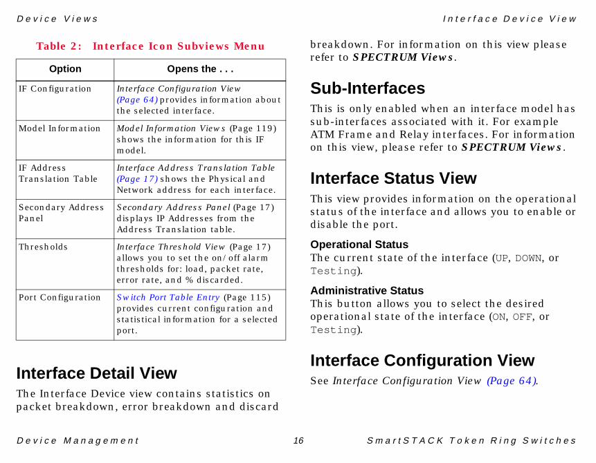
Interface Icon Subviews MenuTable 2 lists the Icon Subviews menu options available for the Interface icon.
Table 2: Interface Icon Subviews Menu
Option Opens the . . .
Detail Interface Detail View (Page 16) displays Packet, Error, and Discard Breakdown pie charts.
Sub-Interfaces This is only valid when an interface model has sub-interfaces associated with it. For example ATM Frame and Relay interfaces. For more information, see the SPECTRUM Views document.
IF Status Interface Status View (Page 16) displays the operational status of the interface.
D e v i c e V i e w s I n t e r f a c e D e v i c e V i e w
D e v i c e M a n a g e m e n t 16 S m a r t S T A C K T o k e n R i n g S w i t c h e s
Interface Detail ViewThe Interface Device view contains statistics on packet breakdown, error breakdown and discard
breakdown. For information on this view please refer to SPECTRUM Views.
Sub-InterfacesThis is only enabled when an interface model has sub-interfaces associated with it. For example ATM Frame and Relay interfaces. For information on this view, please refer to SPECTRUM Views.
Interface Status ViewThis view provides information on the operational status of the interface and allows you to enable or disable the port.
Operational StatusThe current state of the interface (UP, DOWN, or Testing ).
Administrative StatusThis button allows you to select the desired operational state of the interface (ON, OFF, or Testing ).
Interface Configuration ViewSee Interface Configuration View (Page 64).
IF Configuration Interface Configuration View (Page 64) provides information about the selected interface.
Model Information Model Information Views (Page 119) shows the information for this IF model.
IF Address Translation Table
Interface Address Translation Table (Page 17) shows the Physical and Network address for each interface.
Secondary Address Panel
Secondary Address Panel (Page 17) displays IP Addresses from the Address Translation table.
Thresholds Interface Threshold View (Page 17) allows you to set the on/off alarm thresholds for: load, packet rate, error rate, and % discarded.
Port Configuration Switch Port Table Entry (Page 115) provides current configuration and statistical information for a selected port.
Table 2: Interface Icon Subviews Menu
Option Opens the . . .

D e v i c e V i e w s I n t e r f a c e D e v i c e V i e w
D e v i c e M a n a g e m e n t 17 S m a r t S T A C K T o k e n R i n g S w i t c h e s
Model Information ViewSee Model Information Views (Page 119).
Interface Address TranslationTableThis table provides the physical and network addresses associated with the interface index.
Interface IndexThe value that coincides with the interface.
Physical AddressThe MAC address of the interface.
Network AddressThe IP Address of the interface.
Secondary Address PanelThis panel provides a table of IP addresses and masks obtained from the Address Translation Table within the device’s firmware. You can change the current address displayed in the IP Address field by selecting an entry from the table in this panel and clicking the Update button.
Interface Threshold ViewThis view allow you to set the on/off alarm thresholds for the following:
• Load• Packet Rate• Error Rate• % Discarded
Switch Port Table Entry ViewSee Switch Port Table Entry (Page 115).

D e v i c e V i e w s C h a s s i s D e v i c e V i e w
D e v i c e M a n a g e m e n t 18 S m a r t S T A C K T o k e n R i n g S w i t c h e s
Chassis Device ViewThe STS16 models appear in the Chassis Device view as module icons (see Figure 6).
Individual ports within each module are represented by smaller icons that dynamically display current interface information.
Figure 6:Figure 6:Figure 6:Figure 6: STS16 Chassis Device View
Module IconFigure 7 shows a close-up of a Module icon from the STS16 Chassis Device view. Note that there are two types of labels on the icon: those labels that apply to the module as a whole, and those that apply to individual ports.
Figure 7:Figure 7:Figure 7:Figure 7: Module Icon
SpectroGRAPH: Device: JK2
File View Help
1.2
161
ON
1
1.1
160
ON
1
1.3
162
OFF
0
1.4
163
OFF
0
1.5
164
OFF
0
1.6
165
OFF
0
1.7
166
OFF
0
1.8
167
OFF
0
1.9
168
OFF
0
1.10
169
OFF
0
1.11
OFF
0
1.12
OFF
0
1.1
ON
08600
170 171 172
Model Name
Contact
Description
Location
System Up Time
Manufacturer
Device Type
Serial Number
Network Address
Primary Application
1 1
2.2
161
ON
1
2.1
160
ON
1
2.3
162
OFF
0
2.4
163
OFF
0
2.5
164
OFF
0
2.6
165
OFF
0
2.7
166
OFF
0
2.8
167
OFF
0
2.9
168
OFF
0
2.10
169
OFF
0
2.11
OFF
0
2.12
OFF
0
2.1
ON
08601
170 171 1722 1
Tools Bookmarks
MIB-ll 161
1
1.2
ON
160
1
1.1
ON
PortLabels
ModuleLabels
Module
8600
1 1Switch/Module
Number
Type
IF Status
Port PerformanceStatistic
Port Number
Interface Number

D e v i c e V i e w s C h a s s i s D e v i c e V i e w
D e v i c e M a n a g e m e n t 19 S m a r t S T A C K T o k e n R i n g S w i t c h e s
Module LabelsThe following labels are located on each Module icon:
• Switch/Module Number - The switch number, as determined by the port number the switch, is connected in a matrix, or as determined by the Stack Management software, when two switches are connected back to back. The Module number identifies the specific module in the switch. This label also provides double-click access to the Module Notes view (see Table 3).
• Module Type - The type of module plugged into the slot. Module types OC8600(1) and OC860x(860x) represent the motherboard or Base Module.
Module Icon Subviews MenuTable 3 lists the Icon Subviews menu options for module labels in the Chassis Device view.
Switch Module Table EntryAccess: From the Icon Subviews menu from theSwitch/Module Number, select Module Configuration .
This view displays detailed configuration information about the selected module.
Switch NumberThe number of the switch selected.
Module NumberThe number of the module selected.
Module StateThe state of the module. Values include: enable , disable , faulty , and other .
Module TypeThe type of module plugged into the slot. Module types OC8600(1) and OC860x(860x) represent
Table 3: Module Label Icon Subviews Menu
Option Opens the . . .
Module Notes Notes view, which allows you to make, revise, save, retrieve, and mail annotations about the selected module.
Module Configuration
Switch Module Table Entry, which provides more detailed configuration information about the selected module.

D e v i c e V i e w s C h a s s i s D e v i c e V i e w
D e v i c e M a n a g e m e n t 20 S m a r t S T A C K T o k e n R i n g S w i t c h e s
the motherboard or Base Module. Table 26, Module Type Values (Page 100) displays the different types of modules.
Module RevisionThe current module version.
Firmware VersionThe current firmware version.
Number of PortsThe number of ports on this module.
UptimeThe time the module has been up and running.
Max MTU SizeThe maximum transmission unit. This is the maximum frames of octets that can be transmitted.
Port LabelsAs shown on the right side of Figure 7, each selectable port icon on a Module icon comprises four smaller labels. Right clicking anywhere on the port icon lets you access the Icon Subview menu options listed in Table 4.
• Port Number - Identifies a port. Double-click this label to access the Switch Port Table Entry (Page 115).
• Interface Number - Identifies the interface associated with this port. The color of the label indicates the operating condition of the interface (green =up, red =down or testmode).
• IF Status - The status for this interface and the corresponding color for the status (green if the interface is on, orange if the interface is off). Double-click this label to access the Interface Status View (Page 16).
• Port Performance Statistic - Displays whichever performance statistic has been selected in the Gauge Control panel for the interfaces. Double-click this label to access the Fast Ethernet Uplink Performance View (Page 57).
Port Icon Subviews MenuTable 4 lists the Icon Subviews menu options for port labels within the Chassis Device view.

D e v i c e V i e w s C h a s s i s D e v i c e V i e w
D e v i c e M a n a g e m e n t 21 S m a r t S T A C K T o k e n R i n g S w i t c h e s
Table 4: Port Icon Subviews Menu
Option Opens the...
Detail Interface Detail View, which displays statistics on packet, error and discard breakdown. This is described in the SPECTRUM Views document.
IF Status Interface Status View (Page 16) displays the operational status of the interface.
IF Configuration Interface Configuration Table (Page 75) provides information about the selected interface.
IF Address Translation Table
Interface Address Translation Table (Page 17) shows the physical and network address for each interface.
Thresholds Interface Threshold View (Page 17) allows you to set on/off alarm thresholds for load, packet rate, error rate and % discarded.
Port Configuration Switch Port Table Entry (Page 115) provides current configuration and statistical information for a selected port.
Model Information Model Information Views (Page 119) shows the information for this interface.

D e v i c e M a n a g e m e n t 22 S m a r t S T A C K T o k e n R i n g S w i t c h e s
Device Topology Views
This section provides brief descriptions of the Device Topology views available for models of SmartSTACKToken Ring switches in SPECTRUM.
Device Topology views show the connections between a modeled device and other network entities. There are two kinds of Device Topology views available for STS16 models:
• Interface Device Topology View• Chassis Device Topology View (Page 23)
Interface Device TopologyViewAccess: From the Icon Subviews menu for the Deviceicon, select DevTop > Interface .
The lower panel of the Interface Device Topology view (Figure 8) uses interface icons to represent the device’s serial/network I/O ports. These icons provide the same information and menu options as those in the Interface Device View (Page 13). If there is a device connected to a particular interface, a device icon appears on the vertical bar above the interface icon with an icon representing the network group that contains the device. For
more information, refer to the SPECTRUM Views documentation.
Figure 8:Figure 8:Figure 8:Figure 8: Interface Device Topology View
Help
SpectroGRAPH: Device Topology: JK2
File View
JK2
STS16
1 ON1.1
1
0:0:C6:FF:0:410:0:0:0
ISO88025STS16-20RM Tok
2 ON1.2
1
0:0:C6:FF:0:420:0:0:0
ISO88025STS16-20RM Tok
3 ON1.3
1
0:0:C6:FF:0:430:0:0:0
ISO88025STS16-20RM Tok
4 ON1.4
1
0:0:C6:FF:0:440:0:0:0
ISO88025STS16-20RM Tok
SmartSTACK TRSwitch
Tools B ookmarks

D e v i c e T o p o l o g y V i e w s C h a s s i s D e v i c e T o p o l o g y V i e w
D e v i c e M a n a g e m e n t 23 S m a r t S T A C K T o k e n R i n g S w i t c h e s
Chassis Device Topology ViewAccess: From the Icon Subviews menu for the Deviceicon, select DevTop > Chassis .
Figure 9 shows an example of the Chassis Device Topology view. The lower panel of the view uses Interface icons to represent the device’s serial/network I/O ports. The port labels in this view provide the same information and menu options as those described under the Interface Icons (Page 14).
For further information on Device Topology views, refer to the SPECTRUM Views documentation.
Figure 9:Figure 9:Figure 9:Figure 9: Chassis Device Topology View
HelpSpectroGRAPH: Device Topology: JK2
File View
JK2
STS16
1 ON1.1
1
0:0:C6:FF:0:410:0:0:0
ISO88025STS16-20RM Tok
SNMP
1STS16
2 ON1.2
1
0:0:C6:FF:0:420:0:0:0
ISO88025STS16-20RM Tok
3 ON1.3
1
0:0:C6:FF:0:430:0:0:0
ISO88025STS16-20RM Tok
4 ON1.4
1
0:0:C6:FF:0:440:0:0:0
ISO88025STS16-20RM Tok
Tools B ookmarks

D e v i c e M a n a g e m e n t 24 S m a r t S T A C K T o k e n R i n g S w i t c h e s
Application Views
This section describes the Application views and the associated application-specific subviews available formodels of SmartSTACK Token Ring switches in SPECTRUM.
Access: From the Icon Subviews menu for the STS16Device icon, select Application .
When a device model is created, SPECTRUM automatically creates models for each of the major and minor applications supported by the device. The Application view identifies all of these application models, shows their current condition status, and provides access to application-specific subviews.
Figure 10 shows an Application view in its default view mode (icon) where each of the application models is represented by an Application icon (see Figure 11 on Page 25 for a close-up). The Application icons are arranged hierarchically under the STS16 Device icon, with major applications in the top row and their respective minor applications stacked directly below.
If you prefer to see applications displayed by name only, in a single vertical list, select View > Mode > List.
Figure 10:Figure 10:Figure 10:Figure 10: STS16 Application View
SpectroGRAPH: Application: JK2
2_CiscoVT
CiscoVTPA
JK2STS16
STS16App
STS16App
JK2_ATMU
ATMULApp
ATMULApp
JK2_DTRCo
DTRConcAp
DTRConc AppCiscoVTPApp
File V iew Help ÿTools B ookmarks
Model Name
Contact
Description
Location
System Up Time
Manufacturer
Device Type
Serial Number
Network Address
Bridge App
rt Pair App
ce Routing
nning Tree
Bridge_App
dPtPairApp
rfc1525Ap
an_Tree_A
JK2
STS16
JK2_Static
Static_App
JK2_MIB-II
MP2-Agent
JK2_ICMP
ICMP_App
SNMP2_Agent
ICMPApp
IP2_App
JK2_IP
IP2_App
System2_App
JK2_Syste
ystem2_Ap
TCP2_App
JK2_TCP
TCP2_App
Primary Application MIB-ll

A p p l i c a t i o n V i e w s A p p l i c a t i o n I c o n s
D e v i c e M a n a g e m e n t 25 S m a r t S T A C K T o k e n R i n g S w i t c h e s
Application IconsWhen the Application view is in Icon mode, each of the application models is represented by an Application icon (Figure 11). Double-clicking the Model Name label (a) at the top of the icon opens the associated Model Information view—see Model Information Views (Page 119). For some applications, the Model Type label (c) at the bottom of the icon is also a double-click zone, which opens an application-specific view. Any views accessible through these double-click zones are also accessible from the Application icon’s Icon Subviews menu.
Figure 11:Figure 11:Figure 11:Figure 11: Application Icon
Supported ApplicationsSmartSTACK Token Ring switches support both common and device-specific applications.
Applications that are common to many of the different types of devices managed by SPECTRUM are listed in Table 5 along with their corresponding documentation subtopics.
The views and subviews available for SmartSTACK Token Ring Switch device-specific applications are described in the rest of this section, grouped by major application with views listed below them, as follows:
• Cisco VTP Applications (Page 26)- Cisco VTP Management Domain View
(Page 26)- Cisco VTP VLAN Information View (Page 27)- Cisco VTP VLAN Editing View (Page 28)- Cisco Trunk Port Information View
(Page 30)• DTR Concentrator Application (Page 32)
- Concentrator Relay Function View (Page 32)- Spanning Tree Information View (Page 34)- Static/Dynamic Filtering View (Page 35)- (Page 40)
• STS16 Applications (Page 41)- ATM Uplink Application (Page 42)
a Model Name Label / Model Information View
b Condition Status Label
c Model Type Label / Application-Specific View
(a)
(b)
(c)
ÿ������������
�������
�������

A p p l i c a t i o n V i e w s S u p p o r t e d A p p l i c a t i o n s
D e v i c e M a n a g e m e n t 26 S m a r t S T A C K T o k e n R i n g S w i t c h e s
- Fast Ethernet Uplink Configuration (Page 76)
- HSTR ThunderLAN Diagnostics Table (Page 50)
• DTR Mac MIB Applications (Page 51)- dot5 Statistics Information (Page 51)- 802.5 Information for Interface Number
(Page 52)
Cisco VTP ApplicationsThis major application (model type CiscoVTPApp) provides the following application-specific views:
• Cisco VTP Management Domain View• Cisco VTP VLAN Information View (Page 27)• Cisco VTP VLAN Editing View (Page 28)• Cisco Trunk Port Information View (Page 30)
Cisco VTP Management Domain ViewAccess: From the Icon Subviews menu for theCiscoVTPApp Application icon, select ManagementDomain .
This view displays the Management Domain Table. It provides the following information:
IndexThe unique integer identifier of the management domain.
NameThe name of the domain.
Local ModeIndicates whether the system is acting as a VTP Client or as a VTP Server. A third option is transparent which indicates the device is not supporting VTP for this domain.
Rev NoThe current Configuration Revision Number.
Last UpdaterThe IP address of the VTP Server which last updated the Configuration Revision Number.
Last UpdatedThe time at which the Configuration Revision Number was last increased to its current value.
Table 5: Common Applications
Application For more info, see...
Bridging (Gen_Bridge_App) Bridging Applications
MIB-II (SNMP2_Agent) MIB-II Applications
Standard RMON (RMONApp) Management Module Guide for Standard RMON

A p p l i c a t i o n V i e w s S u p p o r t e d A p p l i c a t i o n s
D e v i c e M a n a g e m e n t 27 S m a r t S T A C K T o k e n R i n g S w i t c h e s
Row StatusDisplays whether the row is active or inactive .
TFTP ServerThe IP address of a TFTP Server from which VTP VLAN information for this domain is to be stored.
TFTP PathnameThe complete pathname of the file at the TFTP Server identified by the value of management domain from which VTP VLAN information is to be stored.
Prune StateIndicates whether VTP pruning is enabled or disabled.
Vers In UseDisplays version currently in use.
The Add Entry button accesses the Add Domain Management Table Entry.
Add Domain Management Table EntryAccess: From the Cisco VTP Management Domain view,click the Add Entry button.
From within this view, you can add new entries to the Cisco VTP Management Domain View (Page 26). Fields in this view correspond to the
column headings in the Cisco VTP Management Domain view.
Cisco VTP VLAN Information ViewAccess: From the Icon Subviews menu for theCiscoVTPApp Application icon, select VLAN Information .
Virtual LAN Information includes the following:
IndexNumber identifying the particular VLAN.
VLAN StateThe current state of VLAN. Possible values are: operational , suspended , mtuTooBigForDevice , and mtuTooBigForTrunk .
VLAN TypeThe type of this VLAN. Possible types are: ethernet , fddi , tokenRing , fddiNET , trNet , and vlandeprecated .
NameThe name of this VLAN.
Trans VLAN1A VLAN to which this VLAN would be translational-bridged.
Trans VLAN2A VLAN, other than VLAN1, to which this VLAN would be translational-bridged.
Add Entry

A p p l i c a t i o n V i e w s S u p p o r t e d A p p l i c a t i o n s
D e v i c e M a n a g e m e n t 28 S m a r t S T A C K T o k e n R i n g S w i t c h e s
MTU SizeThe MTU size on this VLAN, defined as the size of largest MAC layer.
SAIDThe value of the 802.10 SAID field which would be used for this VLAN.
Ring No.The ring number for this VLAN.
Bridge No.The bridge number of the VTP-capable switches which would be used for this VLAN.
Stp TypeThe type of Spanning Tree Protocol which would be running on this VLAN.
ParentThe index of the VLAN which would be the parent for this VLAN.
BridgeThe type of bridging mode in use on this VLAN.
Are Hop CountDisplays the maximum number of routing descriptors allowed in All Routes Explorer (ARE) Frames on this VLAN.
Ste Hop CountThe maximum number of routing descriptors allowed in Spanning Tree Explorer (STE) frames on this VLAN.
The two fields at the bottom of the view are described as follows:
VTP VersionThe current version of VTP on the local system.
VLAN Max StorageAn estimate of the maximum number of VLANs from which the local system can recover all VTP information after reboot. If the number of VLANs is greater than this value, then the system cannot act as a VTP server. For a device which cannot estimate this number, the value is 1.
Cisco VTP VLAN Editing ViewAccess: From the Icon Subviews menu for theCiscoVTPApp Application icon, select VTP VLAN Editing .
Virtual Trunk Port VLAN Editing view contains two tables, VLAN Editing Control Table and VLAN Edit Buffer Table (Page 29).
VLAN Editing Control TableThis table provides the means to control the editing of the VLANs for a particular management domain.
A p p l i c a t i o n V i e w s S u p p o r t e d A p p l i c a t i o n s
D e v i c e M a n a g e m e n t 29 S m a r t S T A C K T o k e n R i n g S w i t c h e s
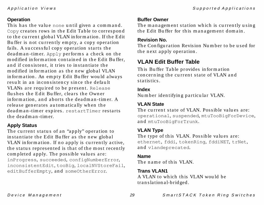
OperationThis has the value none until given a command. Copy creates rows in the Edit Table to correspond to the current global VLAN information. If the Edit Buffer is not currently empty, a copy operation fails. A successful copy operation starts the deadman-timer. Apply performs a check on the modified information contained in the Edit Buffer, and if consistent, it tries to instantiate the modified information as the new global VLAN information. An empty Edit Buffer would always result in an inconsistency since the default VLANs are required to be present. Release flushes the Edit Buffer, clears the Owner information, and aborts the deadman-timer. A release generates automatically when the deadman-timer expires. restartTimer restarts the deadman-timer.
Apply StatusThe current status of an “apply” operation to instantiate the Edit Buffer as the new global VLAN information. If no apply is currently active, the status represented is that of the most recently completed apply. The possible values are: inProgress , succeeded , configNumberError , inconsistentEdit , tooBig , localNVStoreFail , editBufferEmpty , and someOtherError .
Buffer OwnerThe management station which is currently using the Edit Buffer for this management domain.
Revision No.The Configuration Revision Number to be used for the next apply operation.
VLAN Edit Buffer TableThis Buffer Table provides information concerning the current state of VLAN and statistics.
IndexNumber identifying particular VLAN.
VLAN StateThe current state of VLAN. Possible values are: operational , suspended , mtuTooBigForDevice , and mtuTooBigForTrunk .
VLAN TypeThe type of this VLAN. Possible values are: ethernet , fddi , tokenRing , fddiNET , trNet , and vlandeprecated .
NameThe name of this VLAN.
Trans VLAN1A VLAN to which this VLAN would be translational-bridged.

A p p l i c a t i o n V i e w s S u p p o r t e d A p p l i c a t i o n s
D e v i c e M a n a g e m e n t 30 S m a r t S T A C K T o k e n R i n g S w i t c h e s
Trans VLAN2A VLAN, other than VLAN1, to which this VLAN would be translational-bridged.
MTU SizeThe MTU size on this VLAN, defined as the size of largest MAC layer.
SAIDThe value of the 802.10 SAID field which would be used for this VLAN.
Ring No.The ring number for this VLAN.
Bridge No.The bridge number of the VTP-capable switches which would be used for this VLAN.
Stp TypeThe type of the Spanning Tree Protocol (STP) which would be running on this VLAN.
ParentThe index of the VLAN which would be the parent for this VLAN.
BridgeThe type of bridging mode in use on this VLAN.
Are Hop CountDisplays the maximum number of routing descriptors allowed in All Routes Explorer (ARE) Frames on this VLAN.
Ste Hop CountThe maximum number of routing descriptors allowed in Spanning Tree Explorer (STE) frames on this VLAN.
Row StatusDisplays whether row is active or inactive.
The field at the bottom of the view is described as follows:
Notifications EnabledValid options are: True , and False .
Cisco Trunk Port Information ViewAccess: From the Icon Subviews menu for theCiscoVTPApp Application icon, select Trunk PortInformation .
This table contains information on the local system’s VLAN trunk ports. It displays the following information:
IndexThe management domain index on this trunk port.

A p p l i c a t i o n V i e w s S u p p o r t e d A p p l i c a t i o n s
D e v i c e M a n a g e m e n t 31 S m a r t S T A C K T o k e n R i n g S w i t c h e s
Man DomainThe value of the management domain index on this trunk port.
EncapsulationThe type of VLAN encapsulation used on this trunk port.
Native VlanThe Vlan Index of the VLAN which is represented by native frames on this trunk port. For trunk ports not supporting the sending and receiving of native frames, this value should be set to zero.
Row StatusThe status of this row. In some circumstances, the creation of a row is needed to enable the appropriate trunking/tagging protocol on the port, to enable the use of VTP and to assign the port to the appropriate management domain. Frequently, rows in this table will be created as a by-product of other operations.
In JoinsThe number of VTP Join messages sent on this trunk port.
Out JoinsThe number of VTP Out Join messages sent on this trunk port.
Out AdvertsThe number of VTP Advertisement messages which indicated the sender does not support VLAN-pruning received on this trunk port.
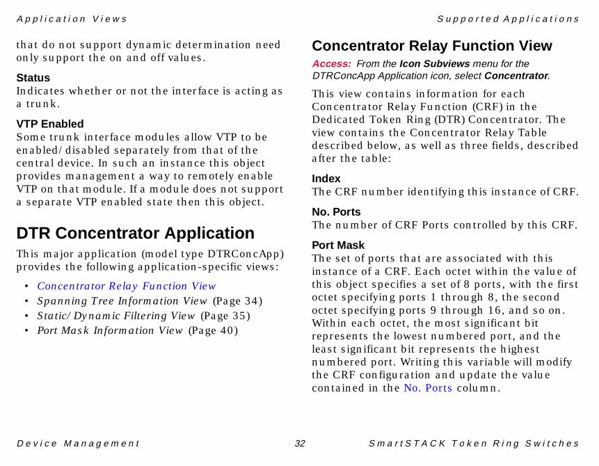
DynamicFor devices that allow dynamic determination of whether a line between two (or more) switches should be a trunk or not, this object allows the operator to mandate the behavior of that dynamic mechanism. On dictates that the interface will always be a trunk. This is the value for static entries (those that show no dynamic behavior). Off allows an operator to specify that the interface is never to be trunk, regardless of any dynamic mechanisms to the contrary. This value is useful for overriding the default behavior of some switches. Desirable is used to indicate that it is desirable for the interface to become a trunk. The device will initiate any negotiation necessary to become a trunk but will not become a trunk unless it receives confirmation from other participants on the link. Auto is used to indicate that the interface is capable and willing to become a trunk but will not initiate trunking negotiations. Other participants on the link are required to either start negotiations or start sending encapsulated packets, on which event the specified interface will become a trunk. Devices
A p p l i c a t i o n V i e w s S u p p o r t e d A p p l i c a t i o n s
D e v i c e M a n a g e m e n t 32 S m a r t S T A C K T o k e n R i n g S w i t c h e s
that do not support dynamic determination need only support the on and off values.
StatusIndicates whether or not the interface is acting as a trunk.
VTP EnabledSome trunk interface modules allow VTP to be enabled/disabled separately from that of the central device. In such an instance this object provides management a way to remotely enable VTP on that module. If a module does not support a separate VTP enabled state then this object.
DTR Concentrator ApplicationThis major application (model type DTRConcApp) provides the following application-specific views:
• Concentrator Relay Function View• Spanning Tree Information View (Page 34)• Static/Dynamic Filtering View (Page 35)• Port Mask Information View (Page 40)
Concentrator Relay Function ViewAccess: From the Icon Subviews menu for theDTRConcApp Application icon, select Concentrator .
This view contains information for each Concentrator Relay Function (CRF) in the Dedicated Token Ring (DTR) Concentrator. The view contains the Concentrator Relay Table described below, as well as three fields, described after the table:
IndexThe CRF number identifying this instance of CRF.
No. PortsThe number of CRF Ports controlled by this CRF.
Port MaskThe set of ports that are associated with this instance of a CRF. Each octet within the value of this object specifies a set of 8 ports, with the first octet specifying ports 1 through 8, the second octet specifying ports 9 through 16, and so on. Within each octet, the most significant bit represents the lowest numbered port, and the least significant bit represents the highest numbered port. Writing this variable will modify the CRF configuration and update the value contained in the No. Ports column.

A p p l i c a t i o n V i e w s S u p p o r t e d A p p l i c a t i o n s
D e v i c e M a n a g e m e n t 33 S m a r t S T A C K T o k e n R i n g S w i t c h e s
NameThe textual name of the CRF. The value of this object is the name of the CRF as assigned by the DTR Concentrator, and is suitable for use in commands entered at the DTR Concentrator console.
Max. InfoThe maximum size of the INFO field the CRF can transmit/receive.
MAC AddressThe MAC address used with the Priority (Page 35) to form the CRF Identifier used in the spanning tree protocol. This address must be unique and it is recommended this address be the specific MAC address of the lowest numbered C-port.
Lan IDThis is the value of the local Lan ID used by the CRF. This value may be assigned or may be learned by the CRF learning process. Valid values range from 0 to 4095 . The value of 65535 indicates that the Lan ID value has not been assigned or learned.
Admin Lan IDWrite to this object to assign the value of the local Lan ID used by the CRF. Valid values range from 0 to 4095 . The value of 65535 indicates that the Lan ID value has not been assigned.
Aging TimeThe time out period in seconds for aging out dynamic entries from the Filtering Database. Recommended default is 300 seconds .
MRI EnableThis object enables or disables the MRI function in the CRF.
Learned DiscardsThe total number of CRF Filtering Database entries, which have been or would have been learned, but have been discarded due to a lack of storage space in the Filtering Database.
The three fields at the bottom of the view are described as follows:
Concentrator AddressMAC address used by DTR Concentrator for uniqueness.
No. of Conc. Relay FunctionsNumber of CRFs within the DTR Concentrator. Writing this object sets the number of CRFs within the DTR Concentrator. The minimum value is 1.
No. of Bridge RelaysNumber of Bridge Relay Functions within the DTR Concentrator. Valid values are: 0 and 1.

A p p l i c a t i o n V i e w s S u p p o r t e d A p p l i c a t i o n s
D e v i c e M a n a g e m e n t 34 S m a r t S T A C K T o k e n R i n g S w i t c h e s
Spanning Tree Information ViewAccess: From the Icon Subviews menu for theDTRConcApp Application icon, select Spanning Tree.
This view consists of seven fields which are described below, and the Spanning Tree Table (Page 35).
Spanning Tree Hold TimeThe minimum time period, in seconds, elapsing between the transmission of Configuration PDUs through a given port (CRF or internal bridge). This is a fixed parameter of the DTR Concentrator used by all member CRF and bridge entities. Value specified by 802.1d is 1 second .
Protocol SpecificationThe version of Spanning Tree Protocol being run on the DTR Concentrator.
Time Since Last ChangeThe time (in 1/100ths of a second) since the last topology change was detected by the CRF or bridge entities within the DTR Concentrator.
No. of Topology ChangesThe total number of topology changes detected by this concentrator since the management entity was last reset or initialized.
Bridge Forward DelayThe value that all spanning tree protocol entities (CRF or Bridge) use for Forward Delay when this spanning tree protocol entity is acting as the root. The range for this parameter is related to the value of Maximum Age (Page 35). The granularity of this timer is specified to be 1 second. An agent may return a “badValue” error if a set is attempted to a value which is not a whole number of seconds.
Bridge Hello TimeThe value that all spanning tree protocol entities (CRF or Bridge) use for Hello Time when this spanning tree protocol entity is acting as the root. The granularity of this timer is specified to be 1 second. An agent may return a “badValue” error if a set is attempted to a value which is not a whole number of seconds.
Bridge Hello Max. AgeThe value that all spanning tree protocol entities (CRF or Bridge) use for Maximum Age when this spanning tree protocol entity is acting as the root. The range for this parameter is related to the value of Bridge Hello Time. The granularity of this timer is specified to be 1 second. An agent may return a “badValue” error if a set is attempted to a value which is not a whole number of seconds.

A p p l i c a t i o n V i e w s S u p p o r t e d A p p l i c a t i o n s
D e v i c e M a n a g e m e n t 35 S m a r t S T A C K T o k e n R i n g S w i t c h e s
Spanning Tree TableThis table contains the spanning tree information for each CRF.
IndexThe CRF number identifying the instance.
PriorityThe value of the writable portion of the CRF Identifier, which are the first two octets of the CRF Identifier. The last 6 octets of the CRF ID are given by the value of the MAC Address (Page 33).
Designated RootThe bridge identifier of the root of the spanning tree as determined by the Spanning Tree Protocol executed at this node.
Root CostThe cost of the path to the root as seen from this CRF.
Root PortThe CRF Port number of the CRF Port which offers the lowest cost path from this CRF to the root.
Maximum AgeThe maximum age of Spanning Tree Protocol information learned from the network on any port (CRF or bridge within the DTR Concentrator)
before it is discarded. Units are in 1/100th of a second. This is the value currently in use.
Hello TimeThe amount of time between transmission of Configuration bridge PDUs used by a CRF that is attempting to become the Root or is the Root. This is the value currently in use.
Forward DelayThe time value, measured in 1/100th of a second, is used to control the amount of time spent in the Listening state when moving from the Blocking state to the Listening state and the amount of time in the Learning state when moving from the Learning state to the Forwarding state. This time value is used for aging dynamic entries in the Filtering Database while the Topology Change flag is set in protocol messages received from the root. This is the value the CRF is currently using.
Static/Dynamic Filtering ViewAccess: From the Icon Subviews menu for theDTRConcApp Application icon, select Filtering .
This view contains two tables; Dynamic MAC Table (Page 36) and Dynamic Route Table (Page 36).

A p p l i c a t i o n V i e w s S u p p o r t e d A p p l i c a t i o n s
D e v i c e M a n a g e m e n t 36 S m a r t S T A C K T o k e n R i n g S w i t c h e s
Dynamic MAC TableThis table contains information about specific dynamic MAC address entries in the CRF Filtering Database.
Index.StationThe Index is a CRF number identifying this instance of CRF. The Station is a unicast MAC address for which the CRF has forwarding information. This object is updated by the Learning Process in the CRF.
Port No.The CRF Port number of the CRF Port that a frame with an address matching Station Address (see Index.Station) has been seen. A value of zero is assigned when Station Address is known, but the CRF Port number has not been learned.
StatusStatus of this entry. See Table 6:
Dynamic Route TableThis table contains information about a specific dynamic route descriptor entry in the CRF Filtering Database.
Table 6: Status of Dynamic MAC Table Entries
Status Description
other Indicates some other MIB object (not the corresponding instance of the Port No., nor an entry in the Static Address Table) is being used to determine if and how frames addressed to the value of the corresponding instance of Station Address are forwarded.
invalid Indicates this entry is no longer valid, but has not been flushed from the table.
learned Indicates the Port No. for this entry was learned, and is being used.
self Indicates this instance of Station Address represents one of the CRF Addresses. The corresponding instance of the Port No’s. indicates which CRF Port has this address.
mgmt Indicates the corresponding instance of Station Address is also a value of an existing Station Address.

A p p l i c a t i o n V i e w s S u p p o r t e d A p p l i c a t i o n s
D e v i c e M a n a g e m e n t 37 S m a r t S T A C K T o k e n R i n g S w i t c h e s
Index.RouteThe Index is the CRF number identifying this instance of CRF. The Route is a Destination Route Descriptor (DRD) for which the CRF has forwarding information. The DRD consists of 2 parts; a 4 bit Bridge Number and a 12 bit LAN ID. This identifies a bridge (BN) which has a port on the local LAN and a port connected to the indicated LAN ID. This object consists of 3 octets so that it can be easily compared with the RI fields of frames with routing information. The first octet contains the BN in the 4 least significant bits. The second octet contains the most significant octet of the LAN ID and the final octet contains the least significant 4 bits of the LAN ID in the 4 most significant bits of the octet.
Port No.The CRF Port number of the CRF Port on which a frame with a DRD matching DRD Route (see Index.Route) has been seen. A value of zero is assigned when DRD Route is known, but the CRF Port number has not been learned.
StatusStatus of this entry. See Table 7:
This button accesses the Static/Dynamic Table (Page 38). This view contains static and dynamic MAC address entries.
Table 7: Status of Dynamic Route Table Entries
Status Description
other This includes the case where some other MIB object is being used to determine how/if a frame containing this DRD is forwarded.
invalid Indicates this entry is no longer valid, but has not been flushed from the table.
learned Indicates the Port No. for this entry was learned.
internal Bridge Relay Function
Indicates DRD Route represents a relay across the Bridge Relay Function of this DTR Concentrator.
mgmt Indicates DRD Route is also a value of an existing Static RD Route in the dtrFdbStaticRDTable.
Static Filtering
A p p l i c a t i o n V i e w s S u p p o r t e d A p p l i c a t i o n s
D e v i c e M a n a g e m e n t 38 S m a r t S T A C K T o k e n R i n g S w i t c h e s
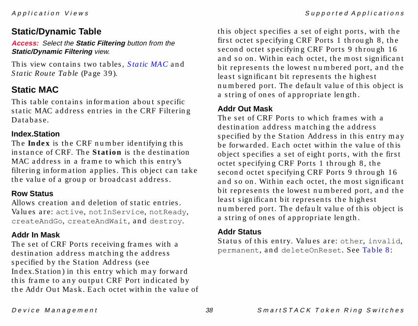
Static/Dynamic TableAccess: Select the Static Filtering button from theStatic/Dynamic Filtering view.
This view contains two tables, Static MAC and Static Route Table (Page 39).
Static MACThis table contains information about specific static MAC address entries in the CRF Filtering Database.
Index.StationThe Index is the CRF number identifying this instance of CRF. The Station is the destination MAC address in a frame to which this entry’s filtering information applies. This object can take the value of a group or broadcast address.
Row StatusAllows creation and deletion of static entries. Values are: active , notInService , notReady , createAndGo , createAndWait , and destroy .
Addr In MaskThe set of CRF Ports receiving frames with a destination address matching the address specified by the Station Address (see Index.Station) in this entry which may forward this frame to any output CRF Port indicated by the Addr Out Mask. Each octet within the value of
this object specifies a set of eight ports, with the first octet specifying CRF Ports 1 through 8, the second octet specifying CRF Ports 9 through 16 and so on. Within each octet, the most significant bit represents the lowest numbered port, and the least significant bit represents the highest numbered port. The default value of this object is a string of ones of appropriate length.
Addr Out MaskThe set of CRF Ports to which frames with a destination address matching the address specified by the Station Address in this entry may be forwarded. Each octet within the value of this object specifies a set of eight ports, with the first octet specifying CRF Ports 1 through 8, the second octet specifying CRF Ports 9 through 16 and so on. Within each octet, the most significant bit represents the lowest numbered port, and the least significant bit represents the highest numbered port. The default value of this object is a string of ones of appropriate length.
Addr StatusStatus of this entry. Values are: other , invalid , permanent , and deleteOnReset . See Table 8:

A p p l i c a t i o n V i e w s S u p p o r t e d A p p l i c a t i o n s
D e v i c e M a n a g e m e n t 39 S m a r t S T A C K T o k e n R i n g S w i t c h e s
Static Route TableA table containing information about specific static route descriptor entries in the CRF Filtering Database.
Index.RouteThe Index is the CRF number identifying this instance of CRF. The Route refers to Static Entries containing DRD information for internal Bridge Ports. These entries are added as part of
the initialization of the DTR Concentrator when an internal Bridge Relay Function is enabled (No. of Bridge Relays =1). The Destination Route Descriptor (DRD) consists of 2 parts; a 4 bit Bridge Number and a 12 bit LAN ID. This identifies a bridge (BN) that has a port on the local LAN and a port connected to the indicated LAN ID. This object consists of 3 octets so that it can be easily compared with the RI fields of frames with routing information. The first octet contains the BN in the 4 least significant bits. The second octet contains the most significant octet of the LAN ID and the final octet contains the least significant 4 bits of the LAN ID in the 4 most significant bits of the octet.
Row StatusAllows creation and deletion of static entries. Values are: active , notInService , notReady , createAndGo , createAndWait , and destroy .
Port NoThe CRF Port on which a frame with a DRD matching route status description (Table 9) in this status is forwarded.
Route StatusStatus of this entry. See Table 9:
Table 8: Status of Static MAC Table Entries
Status Description
other Indicates this entry is currently in use under conditions different from the available status definitions that follow.
invalid Indicates this entry is no longer valid, but has not been flushed from the table. Writing this value to the object removes the entry.
permanent Indicates this entry is currently in use and will remain so after the next reset.
deleteOnReset Indicates the entry is currently in use and will remain so until the next reset.

A p p l i c a t i o n V i e w s S u p p o r t e d A p p l i c a t i o n s
D e v i c e M a n a g e m e n t 40 S m a r t S T A C K T o k e n R i n g S w i t c h e s
The Add Entry button allows you to add new entries to the Static/Dynamic Table (Page 38). Fields in this view correspond to the column headings in the Static/Dynamic Table.
Port Mask Information ViewAccess: From the Icon Subviews menu for theDTRConcApp Application icon, select Port Mask .
This table contains information about the CRF port out mask for specific management functions.
Index.TypeThe Index refers to the CRF number identifying this instance of CRF. The Type identifies the function class for this entry. The MRI forwards frames with a destination class equal to Index.Type using the corresponding mask entry. When the destination class is 0 and the source class is not 0, the destination address in the MAC frame is used to forward the frame. MAC frames with a destination class not found in this table are not forwarded by the MRI.
Port Out MaskThe set of CRF Ports to which frames with a destination class matching the function class specified by the Index.Type in this entry may be forwarded to. Each octet within the value of this object specifies a set of eight ports, with the first octet specifying CRF Ports 1 through 8, the second octet specifying CRF Ports 9 through 16 and so on. Within each octet, the most significant bit represents the lowest numbered port, and the least significant bit represents the highest numbered port.
Table 9: Route Status in Static Route Table
Status Description
other Indicates this entry is currently in use under conditions different from the available status definitions that follow.
invalid Indicates this entry is no longer valid, but has not been flushed from the table.
permanent Indicates the entry is currently in use and will remain so after the next reset.
deleteOnReset Indicates the entry is currently in use and will remain so until the next reset.
Add Entry

A p p l i c a t i o n V i e w s S u p p o r t e d A p p l i c a t i o n s
D e v i c e M a n a g e m e n t 41 S m a r t S T A C K T o k e n R i n g S w i t c h e s
STS16 ApplicationsThis major application (model type STS16App) provides access to the following application-specific subviews via the Icon Subviews menu:
• Power Supply Information View• STS16 Stack Configuration View (Page 94)• Probe/Crosslink Configuration View (Page 104)• TrCRF Configuration View (Page 105)• TrBRF Configuration View (Page 107)• Filter Configuration View (Page 108)
The STS16App is the major application to these three minor applications which will be covered following descriptions of the above icon subviews.
• ATM Uplink Application (Page 42)• Fast Ethernet Uplink Application (Page 49)• High Speed Token Ring Uplink Application
(Page 50)
Power Supply Information ViewAccess: From the Icon Subviews menu for the STS16AppApplication icon, select Power Supply .
This view provides statistical information regarding power supply performance. The table has standard Sort, Find, Update, and Print buttons (see SPECTRUM Views), as well as the following column headings:
SwitchSwitch number as determined by the port number that the switch is connected to in a Matrix or as determined by the Stack Management software when two switches are connected back to back.
Power SupplyThe power supply number. For an OC-8600; 1 is the internal PSU, 2 is the external PSU.
StateThe state indicates the current operational state of the selected power supply. Values are: not-present , operational , failed , ac-Failure , and dc-Failure .
Number ChangesThe number of times the power supply changed state since reset.
Time Since Last ChangeTime ticks since the power supply entered this state.

A p p l i c a t i o n V i e w s S u p p o r t e d A p p l i c a t i o n s
D e v i c e M a n a g e m e n t 42 S m a r t S T A C K T o k e n R i n g S w i t c h e s
ATM Uplink ApplicationThe STS16App provides access to the ATMULApp minor application with the following icon views:
• Permanent Virtual Connections View• Traffic Profiles View (Page 43)• VCC Status Information (Page 46)• ATM Uplink Configuration View (Page 65)• Signaling Configuration View (Page 92)
Permanent Virtual Connections ViewAccess: From the Icon Subviews menu for the ATMULAppApplication icon, select PVC Config .
This view accesses a table for setting up Permanent Virtual Connections (PVCs). The Permanent Virtual Connections Table has standard Sort, Find, Update, Print and Add Entry buttons (see SPECTRUM Views). Column headings are described below.
Index.VPI.VCIThis field specifies Virtual Path Identifier (VPI) and Virtual Channel Identifier (VCI). The null VCC (0/0) is reserved for sending unassigned cells.
ATM AddressSpecifies the target ATM address. Specifying the ATM Address as all zeros is not allowed.
TypeSpecifies the type of configured PVC.
Traffic ProfileValues 0..63 selects a traffic profile for this PVC from the Traffic Profiles View (Page 43). The value (-1) selects the default hardware traffic profile.
VAP IndexSpecifies the VAP to which this PVC belongs.
Row StatusUsed to control creation and deletion of new rows in the table. When a VAP/LEC is deleted (e.g. by writing destroy to Row Status, PVCs belonging to this VAP/LEC are automatically deleted. Values are: active , notInService , notReady , createAndGo , createAndWait , and destroy .
Opens the Add PVC Table Entry view.
Note:Note:
Specifying pvcVpi/pvcVci as 0/0 is not allowed.
Add Entry
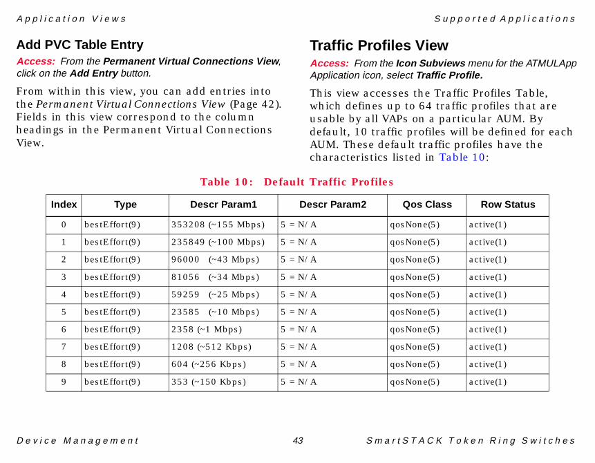
A p p l i c a t i o n V i e w s S u p p o r t e d A p p l i c a t i o n s
D e v i c e M a n a g e m e n t 43 S m a r t S T A C K T o k e n R i n g S w i t c h e s
Add PVC Table EntryAccess: From the Permanent Virtual Connections View ,click on the Add Entry button.
From within this view, you can add entries into the Permanent Virtual Connections View (Page 42). Fields in this view correspond to the column headings in the Permanent Virtual Connections View.
Traffic Profiles ViewAccess: From the Icon Subviews menu for the ATMULAppApplication icon, select Traffic Profile.
This view accesses the Traffic Profiles Table, which defines up to 64 traffic profiles that are usable by all VAPs on a particular AUM. By default, 10 traffic profiles will be defined for each AUM. These default traffic profiles have the characteristics listed in Table 10:
Table 10: Default Traffic Profiles
Index Type Descr Param1 Descr Param2 Qos Class Row Status
0 bestEffort(9) 353208 (~155 Mbps) 5 = N/A qosNone(5) active(1)
1 bestEffort(9) 235849 (~100 Mbps) 5 = N/A qosNone(5) active(1)
2 bestEffort(9) 96000 (~43 Mbps) 5 = N/A qosNone(5) active(1)
3 bestEffort(9) 81056 (~34 Mbps) 5 = N/A qosNone(5) active(1)
4 bestEffort(9) 59259 (~25 Mbps) 5 = N/A qosNone(5) active(1)
5 bestEffort(9) 23585 (~10 Mbps) 5 = N/A qosNone(5) active(1)
6 bestEffort(9) 2358 (~1 Mbps) 5 = N/A qosNone(5) active(1)
7 bestEffort(9) 1208 (~512 Kbps) 5 = N/A qosNone(5) active(1)
8 bestEffort(9) 604 (~256 Kbps) 5 = N/A qosNone(5) active(1)
9 bestEffort(9) 353 (~150 Kbps) 5 = N/A qosNone(5) active(1)

A p p l i c a t i o n V i e w s S u p p o r t e d A p p l i c a t i o n s
D e v i c e M a n a g e m e n t 44 S m a r t S T A C K T o k e n R i n g S w i t c h e s
Index.ProfileIdentifies a particular traffic profile.
TypeSpecifies the traffic descriptor type. These types are combined with a five element parameter vector to describe a Traffic Descriptor. Traffic Descriptors along with a Best Effort Indicator are used to indicate a Conformance Definition. The Type textual convention defines combinations of the ILMI (cf. ATM Forum / af-ilmi-0065.000) Traffic Descriptor Type and Best Effort Indicator values for use with traffic profiles in SSIM-A2-02 and SSIM-A8-02 ATM SmartStack Interface Modules. Values are: atmfNoClpNoScr , atmfNoClpScr , atmfClpNoTaggingScr , atmfClpTaggingScr , bestEffort , and atmClpABR .
Descr Param1 through Param5All of these parameters have the same description. Traffic descriptor dependent parameter; its semantics are dependent on the value in the Type column. Please, refer to the description of the different Traffic Descriptor Types (Type) which describes these changing semantics in detail.
Qos ClassQuality Of Service Class for this traffic profile. The QosClass textual convention is defined to
identify the four service classes specified in the ATM Forum UNI Specification (see Table 11):
Four QoS classes named qos1 , qos2 , qos3 , and qos4 have been specified with the aim to support service classes A, B, C, and D respectively. An unspecified QoS Class named qosNone is used for best effort traffic.
Row StatusUsed to control creation and deletion of new rows in the table. Values are: active , notInService , notReady , createAndGo , createAndWait , and destroy .
Opens the Add Traffic Profiles Entry (Page 45) view.
Table 11: Quality of Service Classes
Class Description
Service Class A Constant bit rate video and Circuit emulation.
Service Class B Variable bit rate video/audio.
Service Class C Connection-oriented data.
Service Class D Connectionless data.
Add Entry
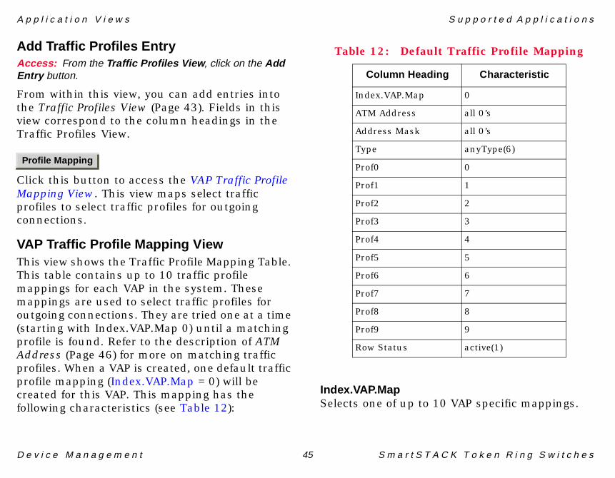
A p p l i c a t i o n V i e w s S u p p o r t e d A p p l i c a t i o n s
D e v i c e M a n a g e m e n t 45 S m a r t S T A C K T o k e n R i n g S w i t c h e s
Add Traffic Profiles EntryAccess: From the Traffic Profiles View , click on the AddEntry button.
From within this view, you can add entries into the Traffic Profiles View (Page 43). Fields in this view correspond to the column headings in the Traffic Profiles View.
Click this button to access the VAP Traffic Profile Mapping View. This view maps select traffic profiles to select traffic profiles for outgoing connections.
VAP Traffic Profile Mapping ViewThis view shows the Traffic Profile Mapping Table. This table contains up to 10 traffic profile mappings for each VAP in the system. These mappings are used to select traffic profiles for outgoing connections. They are tried one at a time (starting with Index.VAP.Map 0) until a matching profile is found. Refer to the description of ATM Address (Page 46) for more on matching traffic profiles. When a VAP is created, one default traffic profile mapping (Index.VAP.Map = 0) will be created for this VAP. This mapping has the following characteristics (see Table 12):
Index.VAP.MapSelects one of up to 10 VAP specific mappings.
Profile Mapping
Table 12: Default Traffic Profile Mapping
Column Heading Characteristic
Index.VAP.Map 0
ATM Address all 0’s
Address Mask all 0’s
Type anyType(6)
Prof0 0
Prof1 1
Prof2 2
Prof3 3
Prof4 4
Prof5 5
Prof6 6
Prof7 7
Prof8 8
Prof9 9
Row Status active(1)

A p p l i c a t i o n V i e w s S u p p o r t e d A p p l i c a t i o n s
D e v i c e M a n a g e m e n t 46 S m a r t S T A C K T o k e n R i n g S w i t c h e s
ATM AddressAfter the Address Mask has been applied (logical AND) to the destination ATM address, the result of this operation is compared to ATM Address. If the two match exactly and the Type matches that of the outgoing connection, the traffic profile specified by Prof0 through Prof9 is tried. If this call is rejected with cause "User cell rate not available", the traffic profile specified by Prof1 is tried and so on. If no match is found in this mapping, the next mapping is tried. This goes on until all mappings for this VAP have been tried. After this the Profile (Page 69) in the Specific VAP Configuration (Page 68) is tried.
Address MaskAn ATM address mask that is applied (logical AND) to the destination ATM address before it is compared to ATM Address of this traffic profile mapping.
TypeSpecifies VCC type of this mapping. Values are: dataDirectVcc , controlDirectVcc , controlDistributeVcc , multicastSendVcc , multicastForwardVcc , and anyType .
Prof0 through Prof9All of these columns have the same description: Prof”x” corresponds to a NULL pointer. 0..63
selects a particular entry in the Index.Profile (Page 44).
Row StatusUsed to control creation and deletion of new rows in the table. When a VAP/LEC is deleted (e.g. by writing destroy to lecRowStatus), traffic profile maps belonging to this VAP/LEC are automatically deleted. Values are: active , notInService , notReady , createAndGo , createAndWait , and destroy .
Opens the Add Mapping Table Entry view.
Add Mapping Table EntryAccess: From the VAP Traffic Profile Mapping View , clickon the Add Entry button.
From within this view, you can add entries into the VAP Traffic Profile Mapping View (Page 45). Fields in this view correspond to the column headings in the VAP Traffic Profile Mapping View.
VCC Status InformationAccess: From the Icon Subviews menu for the ATMULAppApplication icon, select VCC Config .
This table contains status information about all open VCCs on an ATM Uplink Module.
Add Entry

A p p l i c a t i o n V i e w s S u p p o r t e d A p p l i c a t i o n s
D e v i c e M a n a g e m e n t 47 S m a r t S T A C K T o k e n R i n g S w i t c h e s
Index.VPI.VCIThis field specifies the Virtual Path Identifier (VPI) and Virtual Channel Identifier (VCI) of the VCC in question.
UsageUse of the VCC. Values are described in Table 13:
InstncWhen Usage has one of the lane values, Instance holds the number of the corresponding VAP. Instance is not valid for other values of Usage.
Create MeansMeans by which VCC was created. See Table 14.
TxTrafficDescTypeTraffic descriptor type of VCC. Information about possible values and their semantics is listed in Table 15.
Table 13: Usage Values
Usage Value
sscop 1
ilmi 2
oam 3
laneConfig 4
laneControlDirect 5
laneControlDistribute 6
laneMulticastSend 7
laneMulticastForward 8
laneDataDirect 9
Table 14: VCC Creation Values
VCC Creation Value
system 1
pvc 2
incomingPoint2PointSvc 3
outgoingPoint2PointSvc 4
incomingPoint2MultipointSvc 5
outgoingPoint2MultipointSvc 6

A p p l i c a t i o n V i e w s S u p p o r t e d A p p l i c a t i o n s
D e v i c e M a n a g e m e n t 48 S m a r t S T A C K T o k e n R i n g S w i t c h e s
Tx Param1 through Param5Traffic descriptor type dependent parameter. Semantics are dependent on the value of Tx Traffic Descriptor Type.
Qos ClsQuality Of Service Class for the VCC. Values are: qos1 , qos2 , qos3 , qos4 , and qosNone .
TxF DiscShows whether the ATM switch is allowed (true = allowed, false = not allowed) to discard entire (AAL5) frames after having discarded one cell from such a frame. Values are: true , or false .
VCC Service CatService category of VCC. Values are: other(1) , cbr , rtVbr , nrtVbr , abr , and ubr .
ATM AddressWhen Usage has the laneDataDirect value, ATM Address holds the ATM Address of the remote end station or proxy client. ATM Address is not valid for other values of Usage.
Tx FramesNumber of (AAL5) frames transmitted on this VCC.
TxHiByteTogether TxHiByte and TxLoByte implement a virtual 64 bit Tx Bytes counter counting number of bytes transmitted on this VCC. TxHiByte contains the most significant 32 bits and TxLoByte the least significant 32 bits of this virtual counter.
TxLoByteSee description for TxHiByte.
Rx FramesNumber of (AAL5) frames received on this VCC.
RxHiByteTogether RxHiByte and RxLoByte implement a virtual 64 bit Rx Bytes counter counting number bytes received on this VCC. RxHiByte contains
Table 15: Traffic Descriptor Values
Traffic Descriptor Value
atmfNoClpNoScr 3
atmfNoClpScr 6
atmfClpNoTaggingScr 7
atmfClpTaggingScr 8
bestEffort 9
atmClpABR 10

A p p l i c a t i o n V i e w s S u p p o r t e d A p p l i c a t i o n s
D e v i c e M a n a g e m e n t 49 S m a r t S T A C K T o k e n R i n g S w i t c h e s
the most significant 32 bits and RxLoByte the least significant 32 bits of this virtual counter.
RxLoByteSee description for RxHiByte.
Fast Ethernet Uplink ApplicationThe FEULApp provides access to this minor application with the following icon subviews:
• Fast Ethernet Uplink DS21143 View• Fast Ethernet Uplink Configuration (Page 76)• Model Information Views (Page 119)
Fast Ethernet Uplink DS21143 ViewAccess: From the Icon Subviews menu, select DS21143Diagnostics .
This table contains diagnostics counters corresponding to registers in the Digital Semiconductors 21143 chip used on the TB uplink module. The counters are mainly for diagnostics purposes.
Index.PortIndex to identify port on module. Port 1 is the port to the left and port 2 is the port to the right.
Last ResetTime since Last Reset/Creation.
Bytes RcvThe number of bytes received.
Bytes SentThe number of bytes sent.
Frames RcvThe number of frames received.
Frames SentThe number of frames sent.
MCast Bytes RxThe number of multicast bytes received.
Mcast Frames RxThe number of multicast frames received.
Frms Tx DeferredThe number of transmitted frames that have been deferred.
Frms Tx Sngl ColThe number of transmitted frames which had a single collision.
Frms Tx Mltpl ColThe number of transmitted frames which had multiple collisions.
Tx Failed ColThe number of transmitted frames which had failed collisions due to CSMA/CD.
A p p l i c a t i o n V i e w s S u p p o r t e d A p p l i c a t i o n s
D e v i c e M a n a g e m e n t 50 S m a r t S T A C K T o k e n R i n g S w i t c h e s
Tx Fail Carr FailThe number of carrier signals that failed.
Tx Fail Shrt CircThe number of transmitted failed due to short circuiting.
Tx Fail Open CircuitThe number of transmitted failed due to open circuits.
Tx Fail RmtRxThe number of transmitted failures from remote receiver.
Fail Blk ErrThe number of failed bulk errors.
Rx Fail Framing ErrThe number of failed framing errors that have been received.
Rx Fail Frm LongThe number of failed long frames that have been received.
Rx Fail Frm Longrm DestThe number of frames longrm destinations that have been received.
Data OverrunSignifies that the packet contained too much information.
High Speed Token Ring UplinkApplicationThe HSTRULApp provides access to this minor application with the following icon subviews:
• HSTR ThunderLAN Diagnostics Table• HSTR Uplink Configuration Table (Page 86)• Model Information Views (Page 119)
HSTR ThunderLAN Diagnostics TableAccess: From the Icon Subviews menu for theHSTRULApp, select ThunderLAN .
This table contains diagnostics counters corresponding to registers in the Texas Instruments ThunderLAN chip used on the HSTR uplink module.
IndexThe module index selects the appropriate User Expansion Module (UEM, in this case a HSTR Uplink Module) in the switch stack. See Table 22, HSTR Uplink Module Indices (Page 86).
The following counters are mainly for diagnostics purposes:
• Tx Good• Tx Underrun• Tx Deferred

A p p l i c a t i o n V i e w s S u p p o r t e d A p p l i c a t i o n s
D e v i c e M a n a g e m e n t 51 S m a r t S T A C K T o k e n R i n g S w i t c h e s
• Tx Single Coll• Tx Multi Coll• Tx Exces Coll• Tx Late Coll• Rx Good• Rx Overrun• Rx Crc Error• Rx Code Error• Rx Carrier Loss
Last ResetWriting an INTEGER value to this object, causes all statistical counters in this table row to be reset.
DTR Mac MIB ApplicationsThis major application (model type dtrMacApp) provides access to the following application-specific subview via the Icon Subviews menu:
• dot5 Statistics Information
The dtrMacApp is the following two minor applications are described:
• 802.5 Information for Interface Number (Page 52)
• dot5 Statistics Information
dot5 Statistics InformationAccess: From the Icon Subviews menu for thedtrMacMIBApp Application icon, select dot5 Statistics .
This view contains the following statistics:
Isolating Soft Errors
• Line• Burst• A/C• Total
Non-Isolating Soft Errors
• Lost Frames• Congestions• Frame Copied• Recoveries• Token• Total
Hard Errors
• Abort Trans• Internal• Signal Loss• Lobe Wire• Frequency• Total

A p p l i c a t i o n V i e w s S u p p o r t e d A p p l i c a t i o n s
D e v i c e M a n a g e m e n t 52 S m a r t S T A C K T o k e n R i n g S w i t c h e s
802.5 Information for Interface NumberThis view will contain the same fields for all the interfaces.
Access: From the Icon Subviews menu for the dtrIfAppApplication icon, select Configuration .
CommandsValues are: None, Open, Reset , and Close .
dtr Mode SelectValues are: Port , and Station .
Ring SpeedValues are: Unknown, 1-Megabit , 4-Megabits , and 16-Megabits .
Active Monitor ProcessValues are: Participate , and DoNotParticipate .
Functional Address BitmaskThe bit mask of all Token Ring functional addresses for which this port will accept frames.
Ring StateThe current port state with respect to entering or leaving the ring. Values are: Opened, Closed , Opening , and Closing .
Ring Open-StatusThis field indicates the success or reason for failure of the station’s most recent attempt to
enter the ring. Values are: No Open, LobeFailed , Signal Loss , Insertion Timeout , Ring Failed , Beaconing , Duplicate MACAddress , Request Failed , Remove Received , and Open.
Stream NeighborThe MAC address of the upstream neighbor in the ring.
Ring StatusThe current status of the ring. This table displays the following fields which can be checked:
• RingRecovery• SingleStation• RemoveReceived• Auto-RemovalError• LobeWireFault• TransmitBeacon• SoftError• HardError• SignalLoss

D e v i c e M a n a g e m e n t 53 S m a r t S T A C K T o k e n R i n g S w i t c h e s
Performance Views
This section provides brief descriptions of the Performance views available for models of SmartSTACK TokenRing switches in SPECTRUM.
Performance views provide statistical information about the operation of the device and packet frame information for the device and its ports. The following performance views are described in this section:
• ATM Uplink Performance View- VAP LANE and Outbound Performance View
(Page 55)- VAP LANE and Outbound Performance View
- ATM Diagnostics Table (Page 55)• DTR Concentrator Application Performance
View (Page 56)• Fast Ethernet Uplink Performance View
(Page 57)- Virtual Port Statistics Table (Page 57)- Fast Ethernet Virtual Port In Discards View
(Page 58)- Fast Ethernet Virtual Port Out Discards
View (Page 58)• Gen Bridge App (Page 58)• HSTR Uplink Performance View (Page 59)
- HSTR Virtual Port Performance View (Page 60)
• MAC Mib Performance View (Page 60)• Switch Performance View (Page 62)
- Switch Port Performance View (Page 62)• Configuration Views (Page 64)
For more information on Performance views, refer to the SPECTRUM Views documentation.
ATM Uplink Performance ViewAccess: From the Icon Subviews for the ATM ApplicationDevice icon, select Performance .
Figure 12 (Page 54) shows an example of a Performance View. Other performance views described in this section contain different statistics and some may contain graphs.

P e r f o r m a n c e V i e w s A T M U p l i n k P e r f o r m a n c e V i e w
D e v i c e M a n a g e m e n t 54 S m a r t S T A C K T o k e n R i n g S w i t c h e s
Figure 12:Figure 12:Figure 12:Figure 12: Performance View
This view provides the following performance statistics about the packets being passed through the device:
• Index.VAP• Invld Rts• Ring Mismatch• Dup Ring
• Too Large• Long Rte Descr• Blckd MAC Filt• Blckd SAP Filt• CRF Mismatch• EXP Overflow• UF Non Src Rted• UF Spec Rted• UF STE Frame• UF ARE Frame• BF Non Src Rted• BF Spec Rted• BF STE Frame• BF ARE Frame• MF Non Src Rted• MF Spec Rted• MF STE Frame• MF ARE Frame• Rcv High Bytes• Rcv Low Bytes• FF Non Src Rted• FF Spec Rted• FF STE Frames• FF ARE Frame• Fwd High Bytes• Fwd Low Bytes
SpectroGRAPH: IP Address_ATMULApp
øû÷öýûõÿúùùô÷óýþ÷òü
�õ�þ�öÿ�ùÿ�÷ö��ýü��ýóþ�û�û
���÷ó�ÿ�õù�
��û÷ýôÿ��ö��û
��þ�òû�ÿú��û����ýö��òüþýóþ���óû÷ùþ÷òü�òóýþ÷òü
ÿ���� � ��� � ����� ����� � ��������
ATM UpLink Performance View
�òûþ �÷ü� �ù�ýþ� �úøÿ�ûýö�ÿ�þýþ÷�þ÷ó�ÿ�ý�ô� øû÷üþ
�ü�����úø �ü��ÿ�þ��÷ü�ÿ�÷�öýþó���ùÿ�÷ü� �òòÿ�ýû�� �òü�ÿ�þ�ÿ���óû�ôó��ÿ�ú�ÿ�÷ôþ �ôó��ÿ�úøÿ�
�òûþ �÷ü� �ù�ýþ� �úøÿ�ûýö�ÿ�þýþ÷�þ÷ó�ÿ�ý�ô� øû÷üþ
���������������������������� ��� ������������
�ü�����ýù �ó�ÿ�÷��ÿ�õþ���ó�ÿ�ò�ÿ�õþ����ÿ�òüÿ�ûóÿ�þ����ÿ�ù�óÿ�þ��ÿ��ÿ���ÿ�ûýö���ÿú��ÿ�ûýö�

P e r f o r m a n c e V i e w s A T M U p l i n k P e r f o r m a n c e V i e w
D e v i c e M a n a g e m e n t 55 S m a r t S T A C K T o k e n R i n g S w i t c h e s
• Inactiv VAPs• Blocked VAPs• ODF Blckd SAP• ODF Too Large• TF Non Src Rted• TF Spec Rted• TF STE Frame• TF ARE Frame• Tx High Bytes• Tx Low Bytes• Last Reset
VAP LANE and OutboundPerformance ViewAccess: From the ATM Uplink Performance View , selectthe VAP LANE/Outbound Statistics button.
This view provides the following performance statistics about the packets being passed through the device. If contains two tables, VAP Lane Statistics Table and Outbound Statistics Table.
VAP Lane Statistics Table• Index.VAP• VCC Discon Events• VCC Fnd Events• Last Reset
Outbound Statistics Table• Index.VAP• Bad Channels• Invalid Tags• Last Reset
VAP LANE and OutboundPerformance View - ATMDiagnostics TableAccess: From the ATM Uplink Performance View , selectthe ATM Diagnostics button.
This view provides the following performance statistics about the packets being passed through the device:
• Index• Dropped Pckts• Crc Errors• Overflow• Too Long• Too Short• Unknown VCC• Rcv High Byte• Rcv Low Byte• Tx High Byte• Tx Low Byte• Last Reset

P e r f o r m a n c e V i e w s C t r o n A T M A p p
D e v i c e M a n a g e m e n t 56 S m a r t S T A C K T o k e n R i n g S w i t c h e s
Ctron ATM AppAccess: From the Icon Subviews menu for the Ctron ATMApp Application Device icon, select Performance .
This view provides the following performance statistics about the packets being passed through the device:
• In Load• In Cell Rate• Eror Rate• Out Load• Out Cell Rate• % Discard
Cisco VTP ApplicationPerformance ViewAccess: From the Icon Subviews menu for theCiscoVTPApp Application Device icon, select Performance .
This view provides the following performance statistics about the packets being passed through the device:
• Index• Summary• In Subset• In Requests
• Out Summary• Out Subset• Out Requests• Rev. No. Errors• Digest Errors
DTR Concentrator ApplicationPerformance ViewAccess: From the Icon Subviews menu for the DTRConcentrator Application Device icon, select Performance .
This view provides the following performance statistics about the packets being passed through the device:
• Index.Port• IN ARE Frames• Out ARE Frames• In Frames• Out Frames• In SRF Frames• Out SRF Frames• In STE Frames• Out STE Frames• Invalid RI• In Misdirected• In Discard

P e r f o r m a n c e V i e w s F a s t E t h e r n e t U p l i n k P e r f o r m a n c e V i e w
D e v i c e M a n a g e m e n t 57 S m a r t S T A C K T o k e n R i n g S w i t c h e s
Fast Ethernet UplinkPerformance ViewAccess: From the Icon Subviews menu for the FEULAppApplication icon, select Performance .
Physical port statistics counting LLC frames.
• Invld VLANs• Invld Rtes• Invld VLAN Tag• IDF Too Lar• IDF Block Mac Addr• IDF Block SAP• IDF CRF Mismatch• IDF Blckd VPorts• IDF Not Rec• UF Non Src Rtd• BF Non Src Rtd• MF Non Src Rtd• RX High Bytes• RX Low Bytes• FF Non Src Rtd• FF Non Spec Rtd• FF STE • FF ARE• Fwd High Byte• Fwd Low Byte
• Invld Hdr Tag• Blocked VP• ODF Block SAP• ODF Too Large• ODF Bcast Over• TF non Src Rtd• Tx High Bytes• Tx Low Bytes• Last Reset
Virtual Port Statistics TableAccess: From the Fast Ethernet Uplink PerformanceView, select the Virtual Port Statistics button.
This view provides the following performance statistics about the packets being passed through the device:
• Rx Frames• Fwd Frames• Tx Frames• Last Reset

P e r f o r m a n c e V i e w s G e n B r i d g e A p p
D e v i c e M a n a g e m e n t 58 S m a r t S T A C K T o k e n R i n g S w i t c h e s
Fast Ethernet Virtual Port InDiscards ViewAccess: From the Virtual Port Statistics Table , select theInbound Discards button.
This view provides the following performance statistics about the packets being passed through the device:
• IP No Trans• IP Trans Err• IP Frag Err• IPX No Trans• IPX Trans Err• Net Bios No Tran• Net Bios Tran Err• SNA No Trans• SNA Trans Err• SNAP No Trans• SNAP Trans Err• Gen No Trans • Gen Trans Err
Fast Ethernet Virtual Port OutDiscards ViewAccess: From the Virtual Port Statistics Table , select theOutbound Discards button.
This view provides the following performance statistics about the packets being passed through the device:
• Rx Frames• Fwd Frames• Tx Frames• Last Reset
Gen Bridge AppAccess: From the Icon Subviews menu for the Gen BridgeApp Application Device icon, select Performance .
This view provides the following performance statistics about the packets being passed through the device:
• Received Rate• % Filtered• % Forwarded• Transmitted Rate

P e r f o r m a n c e V i e w s H S T R U p l i n k P e r f o r m a n c e V i e w
D e v i c e M a n a g e m e n t 59 S m a r t S T A C K T o k e n R i n g S w i t c h e s
HSTR Uplink PerformanceViewAccess: From the Icon Subviews menu for theHSTRULApp Application icon, select Performance .
Physical port statistics counting LLC frames.
• Invld VLAN• Invld Rtes• Invld VLAN Tag• Ring No Mis• Dup Ring No• IDF Too Lar• IDF Long Rte Descr• IDF Block MAC Addr• IDF Block SAP• IDF CRF Mismatch• IDF Exp Overflows• IDF Blkd VPorts• UF Non Src Rtd• UF Spec Rtd• UF STE• UF ARE• BF Non Src Rtd• BF Spec Rtd• BF STE• BF ARE
• MF Non Src Rtd• MF STE• MF ARE• Rx High Byte• Rx Low Byte• FF Non Src Rtd• FF Spec Rtd• FF STE• FF ARE• Fwd High Byte• Fwd Low Byte• Invld Hdr Tag• Unknown ring• Inactive VP• ODF Block SAP• ODF Too Large• TF Non Src Rtd• TF Spec Rtd• TF STE• TF ARE• Tx high Byte• Tx Low Byte• MAC Rx• MAC Tx• Last Reset• ODF Inv Rte

P e r f o r m a n c e V i e w s M A C M i b P e r f o r m a n c e V i e w
D e v i c e M a n a g e m e n t 60 S m a r t S T A C K T o k e n R i n g S w i t c h e s
HSTR Virtual Port PerformanceViewAccess: From the HSTR Uplink Performance view, clickthe Virtual Port button.
This view provides the following performance statistics about the packets being passed through the device:
• RX Frames• Fwd Frames• Tx Frames• Last Reset
MAC Mib Performance ViewAccess: From the Icon Subviews menu for the MAC MibApplication Device icon, select Performance .
This view provides the following performance statistics about the packets being passed through the device:
• Load• Frame Rate• % Error
MIB-ll Performance ViewAccess: From the Icon Subviews menu for the MIB-llApplication Device icon, select Performance .
This view provides the following performance statistics about the packets being passed through the device:
• Frame Rate• % Received• % Transmitted• % Error• % Discarded
Port Performance ViewAccess: From the Icon Subviews menu for a selected portlabel in either the Chassis Device view or the ChassisDevice Topology view, select Port Performance .
This view provides the following statistical information about packet traffic through the selected port:
• Load• Packet Rate• % Error • % Discarded

P e r f o r m a n c e V i e w s P o r t P e r f o r m a n c e V i e w
D e v i c e M a n a g e m e n t 61 S m a r t S T A C K T o k e n R i n g S w i t c h e s
SNMP Agent Detail ViewAccess: From the MIB-ll Performance View , select theDetail button.
This view provides the following performance statistics about the packets being passed through the device:
Packet Break Down
• Received• Transmitted• Errors• Discarded• Total
Errors in Breakdown
• ASN Parse Errs• Too Big• No Such Name• Bad Values• Gen Errs• Total
Errors Out Breakdown
• Too Big• No Such Name• Bad Values• Gen Errs• Total
Discard Breakdown
• Bad Versions• Bad Comm Name• Bad Comm Uses• Total
Receive Breakdown
• Get Requests• Get Nexts• Set Requests• Total
Transmit Breakdown
• Get Responses• Out Traps• Total
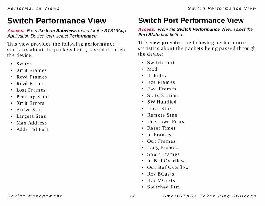
P e r f o r m a n c e V i e w s S w i t c h P e r f o r m a n c e V i e w
D e v i c e M a n a g e m e n t 62 S m a r t S T A C K T o k e n R i n g S w i t c h e s
Switch Performance ViewAccess: From the Icon Subviews menu for the STS16AppApplication Device icon, select Performance .
This view provides the following performance statistics about the packets being passed through the device:
• Switch• Xmit Frames• Rcvd Frames• Rcvd Errors• Lost Frames• Pending Send• Xmit Errors• Active Stns• Largest Stns• Max Address• Addr Tbl Full
Switch Port Performance ViewAccess: From the Switch Performance View , select thePort Statistics button.
This view provides the following performance statistics about the packets being passed through the device:
• Switch.Port• Mod• IF Index• Rce Frames• Fwd Frames• Stats Station• SW Handled• Local Stns• Remote Stns• Unknown Frms• Reset Timer• In Frames• Out Frames• Long Frames• Short Frames• In Buf Overflow• Out Buf Overflow• Rcv BCasts• Rcv MCasts• Switched Frm

P e r f o r m a n c e V i e w s S w i t c h P e r f o r m a n c e V i e w
D e v i c e M a n a g e m e n t 63 S m a r t S T A C K T o k e n R i n g S w i t c h e s
• Pkts In Err• Addr Chain Over• Config Loss• Cfg Loss RC• Auto Disable RC
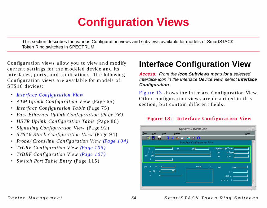
D e v i c e M a n a g e m e n t 64 S m a r t S T A C K T o k e n R i n g S w i t c h e s
Configuration Views
This section describes the various Configuration views and subviews available for models of SmartSTACKToken Ring switches in SPECTRUM.
Configuration views allow you to view and modify current settings for the modeled device and its interfaces, ports, and applications. The following Configuration views are available for models of STS16 devices:
• Interface Configuration View• ATM Uplink Configuration View (Page 65)• Interface Configuration Table (Page 75)• Fast Ethernet Uplink Configuration (Page 76)• HSTR Uplink Configuration Table (Page 86)• Signaling Configuration View (Page 92)• STS16 Stack Configuration View (Page 94)• Probe/Crosslink Configuration View (Page 104)• TrCRF Configuration View (Page 105)• TrBRF Configuration View (Page 107)• Switch Port Table Entry (Page 115)
Interface Configuration ViewAccess: From the Icon Subviews menu for a selectedInterface icon in the Interface Device view, select InterfaceConfiguration .
Figure 13 shows the Interface Configuration View. Other configuration views are described in this section, but contain different fields.
Figure 13:Figure 13:Figure 13:Figure 13: Interface Configuration View
SpectroGRAPH: JK2
þùøý÷úÿöüÿõûú÷��ý÷����÷ÿõùü÷
��ý÷����÷ÿ���÷�
�÷ý����ÿ����÷øø���÷�ÿ���ý��ý�÷ø��ûüýû������ýû��
ÿ���� � ��� � ����� ����
�ü÷��ýû��ÿþý�ý�ø
Interface Configuration View
� ��������
��úû��ÿþý�ý�ø
��øýÿ�����÷
��ÿ����÷øø��÷ý����ÿ��ø� ��ùøû���ÿ����÷øø
�����û�ý�
����÷ýÿþû�÷
��÷�÷ÿ�÷��ý�
C o n f i g u r a t i o n V i e w s A T M U p l i n k C o n f i g u r a t i o n V i e w
D e v i c e M a n a g e m e n t 65 S m a r t S T A C K T o k e n R i n g S w i t c h e s
This view provides the following information for the selected interface:
Operation StatusThe current operational state of the interface (Up, Down, or Testing ).
Admin. StatusThe desired operational state of the interface (Up, Down, or Testing ).
Last ChangeThe System UpTime value when the interface entered its current operational state.
IP Address/Network MaskThis window provides a list of the user-defined names and IP addresses for the interface.
Physical AddressThe Ethernet (MAC) address of the interface.
BandwidthThe estimated bandwidth of the interface, measured in bits per second. For interfaces that do not vary in bandwidth, or no accurate estimate can be made, a nominal bandwidth is provided.
Packet SizeThe largest packet that can be transmitted or received by the port, displayed in octets.
Queue LengthThe length of the outbound packet queue, in packets.
Func AddrEnables the IEEE Spanning Tree Protocol at the TrBRF level to use the IBM bridge functional.
ATM Uplink ConfigurationViewAccess: From the Icon Subviews menu for the ATMULAppApplication icon, select Configuration .
This view contains the ATM Uplink Info Table. It provides information about hardware and software version numbers. The buttons at the bottom of the view are described after the ATM Uplink Info Table.
IndexThe module index selects the appropriate ATM Uplink Module (AUM) in the switch stack. The module’s indices are assigned in Table 16 (Page 66). The index field in certain views associated with this view correlates back to this Index description:

C o n f i g u r a t i o n V i e w s A T M U p l i n k C o n f i g u r a t i o n V i e w
D e v i c e M a n a g e m e n t 66 S m a r t S T A C K T o k e n R i n g S w i t c h e s
HW Product IDA string containing the hardware product ID.
HW VersionA string containing the hardware version.
HW ECO LevelA string containing the ECO update level.
HW Serial No.A string containing the hardware serial number.
SW Product IDA string containing the software product ID.
SW VersionA string containing the software version.
SW ECO LevelA string containing the ECO update level.
Boot PromA string containing the Bootprom version number.
This button accesses the Common VAP Configuration View (Page 67), which contains configuration variables common to all Virtual ATM Ports (VAPs) of a given AUM.
This button accesses the Port Hardware Setup View (Page 72). This view contains configuration variables that control different properties of the physical ATM port.
This button accesses the Message Logs View (Page 72). This view implements a buffer containing the last 10 log messages generated by the ATM Uplink.
Table 16: ATM Uplink Module Indices
ATM Uplink Module Description
atmUplinkModuleIndex 1 Leftmost AUM in switch number 1
atmUplinkModuleIndex 2 Rightmost AUM in switch number 1
atmUplinkModuleIndex 3 Leftmost AUM in switch number 2
atmUplinkModuleIndex 4 Rightmost AUM in switch number 2
atmUplinkModuleIndex 16 Rightmost AUM in switch number 8
VAP Configuration
Port Hardware
Message Log

C o n f i g u r a t i o n V i e w s A T M U p l i n k C o n f i g u r a t i o n V i e w
D e v i c e M a n a g e m e n t 67 S m a r t S T A C K T o k e n R i n g S w i t c h e s
This button access the LED Status Table (Page 73). This view shows the state of the front panel LEDs of each AUM.
Common VAP Configuration ViewAccess: In the ATM Uplink Configuration view, click theVAP Configuration button.
This view contains the Common VAP Info Table which provides configuration variables common to all VAPs of a given AUM. In addition to the columns described below, there are two buttons at the bottom of the view. These buttons access information about configuration variables and MAC address connections.
IndexThe module index selects the appropriate ATM Uplink Module (AUM) in the switch stack. The module’s indices are assigned in Table 16 (Page 66).
Svc SupportSpecifies whether SVCs are supported by the ATM switch to which the AUM is connected. Values are: yes , and no.
Addr Reg SupportAdministrative status of ILMI address registration. Values are: supported , and unsupported .
Number VCCControls the total number of VCCs available to all VAPs on the AUL.
No. DestinationControls the total number of destinations available to all VAPs on the AUL.
UNI VersionControls the UNI version to be used. Default value is version3point1 .
Max Line RateControls the maximum total peak-rate of the physical link between the AUL and the ATM switch.
Reset CtrsWriting an INTEGER value to this object, resets statistics counters in this AUL.
Module StateThe module state provides a finer granularity of information on the operational state of the AUL than what can otherwise be read from ifOperStatus. The states have the following semantics—see Table 17 (Page 68):
LED Status
C o n f i g u r a t i o n V i e w s A T M U p l i n k C o n f i g u r a t i o n V i e w
D e v i c e M a n a g e m e n t 68 S m a r t S T A C K T o k e n R i n g S w i t c h e s
Accesses the Specific VAP Info Table, which contains configuration variables specific to each VAP. This table is described in the Specific VAP Configuration below.
Accesses the MAC Address Connections (Page 71) For each VAP, this view maps MAC addresses to VPI/VCI pairs.
Specific VAP ConfigurationAccess: From the Common VAP Configuration table,select the Specific VAP button.
This view contains configuration variables specific to each Virtual ATM Port (VAP).
Index.VAPIdentifies a VAP within a switch stack.
LEC IndexThis variable holds the LEC MIB lecIndex corresponding to this VAP.
Addr AssignControls assignment of the VAP/LEC ATM address. When set to manual , an ATM address must be specified in ATM Address, otherwise,
Table 17: Module States
Module State Description
unknown The module state is unknown.
disabled The module is administratively disabled.
booting The module is coming up. The module will normally enter the "down" state once booting completes.
down The module has booted successfully and may now be configured. Once configured, it can be brought to the operational state up(6).
goingUp The module is coming into the operational state up.
up The module is operational and VAPs can now be brought into their operational state thereby enabling traffic across the AUM. This state maps to an operational state "up". All other values of Module State maps to an operation state "down".
goingDown The module is being taken out of the operational state.
failing The module has failed. Rebooting will normally be required to bring it out of this state.
Specific VAP
Address Conn
C o n f i g u r a t i o n V i e w s A T M U p l i n k C o n f i g u r a t i o n V i e w
D e v i c e M a n a g e m e n t 69 S m a r t S T A C K T o k e n R i n g S w i t c h e s
when automatic , the ATM address is generated automatically.
ATM AddressWhen Addr Assign is set to manual , ATM Address must specify an ATM address for the VAP/LEC. An ATM address of all zeros is not allowed.
LEC ATM AddressSpecifies an ATM address to use when attempting to connect to the LAN Emulation Configuration Server (LECS) to be used for the VAP/LEC. Defaults to an ATM address of all zeros indicating that LEC ATM Address is not configured. Setting LEC ATM Address to all zeros effectively removes any earlier user-specified LECS ATM Address for the VAP/LEC.
LEC VpiSetting LEC Vpi/LEC Vci to 0/0 effectively removes any earlier user-specified LECS PVC (vapLecsVpi/vapLecsVci) for the VAP/LEC in question. Regarding the semantics of this object, please see the reference in the description LEC ATM Address.
LEC VciSee description of LEC Vpi.
Guar VCCAll VAPs on a particular AUM allocate VCCs from a common pool. Guar VCC specifies the number
VCCs that the VAP will be guaranteed from this pool.
Guar DestAll VAPs on a particular ATM Uplink Module allocate destination STEVs from a common pool. Guar Dest specifies the number destination STEVs that the VAP will be guaranteed from this pool.
ProfileThe traffic profile to be used if no traffic profile mapping matches the VCC to be opened. Values of 0..63 selects a profile from the Traffic Profiles View (Page 43); (-1 ) selects the hardware default traffic profile.
Note:Note:
The sum of Guar VCC from all VAPs on a particular AUM must not exceed Number VCC for this AUM.
Note:Note:N
The sum of Guar Dest from all VAPs on a particular AUM must not exceed No. Destination for this ATM Uplink Module.

C o n f i g u r a t i o n V i e w s A T M U p l i n k C o n f i g u r a t i o n V i e w
D e v i c e M a n a g e m e n t 70 S m a r t S T A C K T o k e n R i n g S w i t c h e s
Rx Rate DifThis is the maximum difference (in cells/s) there can be between the requested receive rate of an incoming call (called the forward rate) and the line rate (353208 cells/s) before a call is rejected with the cause "User cell rate not available.".
This is done to ensure interoperability with equipment, which does not handle call-rejection (with cause "User cell rate not available") according to the ATM Forum LANE 1.0 specification.
Tx Rate DifThis is the maximum difference (in cells/s) there can be between the requested transmit rate of an incoming call (called the backward rate) and the line rate (353208 cells/s) before a call is rejected with the cause "User cell rate not available.".
This is done to ensure interoperability with equipment, which does not handle call-rejection (with cause "User cell rate not available") according to the ATM Forum LANE 1.0 specification.
Trace MaskThis is essentially a 32 bit mask controlling log message output. Log messages are collected in the Message Logs View (Page 72) defined in the status section below.
Reset CtrWriting an INTEGER value to this object, resets all counters specific to this VAP.
Reset AddrWriting an INTEGER value to this object, clears address table entries pertaining to this VAP.
Explorer RateExplorer frame forwarding rate per second throttle. A value of (-1 ) disables explorer frame throttling for this VAP.
Spanning ModeUsed when configuring manual spanning tree. Setting this object to forwarding or blocking overrides the spanning tree algorithm for this VAP. Setting this object to auto turns the spanning tree algorithm on for this VAP. Setting
Note:Note:
The default value of this parameter (max value) effectively disables the checking on the requested receive rate.
Note:Note:
The default value of this parameter (max value) effectively disables the checking on the requested transmit rate.

C o n f i g u r a t i o n V i e w s A T M U p l i n k C o n f i g u r a t i o n V i e w
D e v i c e M a n a g e m e n t 71 S m a r t S T A C K T o k e n R i n g S w i t c h e s
this object to unknown is not allowed. Values are: auto , forwarding , blocking , and unknown .
StateThe State provides a finer granularity of information on the operational state of the VAP than what can otherwise be read from ifOperStatus. The states have the following semantics—see Table 18:
Max TransmitMTU size of this virtual port.
MAC Address ConnectionsAccess: From the Common VAP Configuration table,select the Address Conn button.
For each VAP, the MAC Address Connections table maps MAC addresses to VPI/VCI pairs.
Index.VAP.MACIdentifies the VAP MAC address.
Table 18: VAP States
VAP State Description
unknown The VAP state is unknown.
disabled The VAP is administratively disabled. Normally, State will be adminDown when the VAP is administratively disabled, however, in situations where the VAP is not assigned to a VLAN, it will show up as disabled instead.
goingUp The VAP is coming into one of its operational states.
up The VAP is in operational state, but due to the spanning tree algorithm it is not forwarding frames, i.e. the VAP is up but not forwarding. forwarding is the "real" operational state.
goingAdminDown The VAP has been administratively disabled but has not reached the stable adminDown state yet.
adminDown The VAP is administratively disabled.
failed The VAP has failed. The Message Log Table should hold information about the cause of the failure.
waitingForModuleUp The VAP is waiting for the module to come up.
forwarding The VAP is in operational state, capable of forwarding frames.
Table 18: VAP States (Continued)

C o n f i g u r a t i o n V i e w s A T M U p l i n k C o n f i g u r a t i o n V i e w
D e v i c e M a n a g e m e n t 72 S m a r t S T A C K T o k e n R i n g S w i t c h e s
VPIVirtual Path Identifier (VPI) of VCC connecting the AUM to the destination identified by the MAC Address.
VCIVirtual Channel Identifier (VCI) of VCC connecting the AUM to the destination identified by the MAC Address.
Port Hardware Setup ViewAccess: In the ATM Uplink Configuration view, click thePort Hardware button.
This view shows the Port Hardware Table which contains configuration variables that control different properties of the physical ATM port. The four column headings in this table are described below.
IndexThe module index selects the appropriate ATM Uplink Module (AUM) in the switch stack. The module’s indices are assigned in Table 16 (Page 66).
Master TimingControls the source of the ATM transmitter timing. Values are: network which makes the transmitter synchronize with the incoming traffic
on the receiver; and local which makes the transmitter generate its own timing.
Framing ModeControls the TC framing mode. Values are: sdh , and sonet .
Empty CellsControls whether the ATM frame emits idle or unassigned cells when there is no data to send.
Message Logs ViewAccess: This view can be accessed from three differentplaces: ATM Uplink Configuration , Fast Ethernet UplinkConfiguration , or HSTR Uplink Configuration. From allthree views, click the Message Log button.
The Log Message Table implements a buffer containing the last 10 log messages generated by the ATM Uplink. The buffer is written cyclically which means that the message with index 1 is not necessarily the oldest. A time stamp Message Time is recorded for each log message; it contains the value of MIB-II’s sysUpTime object at the time of the log message occurrence. Log message output may be controlled using Trace Mask (Page 70) in the Specific VAP Configuration (Page 68).
Index.LogIndex into cyclical buffer.

C o n f i g u r a t i o n V i e w s S T S 1 6 C o n f i g u r a t i o n V i e w
D e v i c e M a n a g e m e n t 73 S m a r t S T A C K T o k e n R i n g S w i t c h e s
Message TimeValue of MIB-II’s sysUpTime at the time of occurrence of the logged event.
Message TextLog message text.
LED Status TableAccess: In the ATM Uplink Configuration view, click theLED Status button.
This view shows a simple table illustrating the state of the front panel LEDs of each AUM. The five column headings are described below.
IndexThe module index selects the appropriate ATM Uplink Module (AUM) in the switch stack. The module’s indices are assigned in Table 16 (Page 66).
DiagnosticDiagnostics LED state. Values are: on and off .
ErrorError LED state. Values are: on and off .
Signal LossThe loss of the transmission signal. Values are: on and off .
Receive SyncThe receive synchronization signal. Values are: on and off .
STS16 Configuration ViewAccess: From the Device Topology Interface view, selectConfiguration from the Icon Subviews menu.
The STS Configuration contains the following fields and buttons, and the Interface Configuration Table. Descriptions are as follows:
Contact StatusThe contact status of the model.
Number of InterfacesThe number of interfaces on the model.
Opens the Redundancy and Model Reconfiguration Options (Page 74), which allows you to configure and model redundancy.
Open the Interface Address Translation Table (Page 75), which displays the MAC and IP addresses for the interface.
Redundancy and Model Reconfiguration Options
Interface Address Translation

C o n f i g u r a t i o n V i e w s S T S 1 6 C o n f i g u r a t i o n V i e w
D e v i c e M a n a g e m e n t 74 S m a r t S T A C K T o k e n R i n g S w i t c h e s
Redundancy and ModelReconfiguration OptionsAccess: From the STS Configuration View , click on theRedundancy and Model Reconfiguration Options button.
Displays buttons allowing you to configure the model and redundancy.
Redundancy Administrative Status?Enabling Redundancy will cause Spectrum to update this model when the Primary Address is not accessible and a list of redundant preferred addresses exist.
Generate Redundancy Alarms?Having this option set to true will cause Spectrum to generate alarms when Redundancy intelligence updates the Network Address.
Automatically Reconfigure Interfaces?This button determines if Spectrum should monitor for changes in the number of interfaces. Setting this option to false will prevent Spectrum from detecting any such changes.
Create Sub-Interfaces?If this device supports RFC1573, this button determines whether Spectrum should model its sub-interfaces or not. If true , these models will be displayed in the Sub-Interface view of the Physical Interface model.
Reconfigure due to LINK UP/DOWN events?Setting this option to true will cause Spectrum to remodel this device’s interfaces whenever the device sends out a LINK UP or LINK DOWN event.
Device Discovery after Reconfiguration?This button determines if Spectrum should update its knowledge of connections off a model’s interfaces, after a model reconfiguration occurs.
Topologically Relocate Model?Having this button set to true allows Spectrum to relocate the model to a different topological locations as part of the AutoDiscovery process.
This button forces Spectrum to re-evaluate all interface models. It will also force a Device Discovery if that option is enabled.
This button forces a Device Discovery to discover the model’s connection.
Reconfigure Model
Discover LANs

C o n f i g u r a t i o n V i e w s I n t e r f a c e C o n f i g u r a t i o n T a b l e
D e v i c e M a n a g e m e n t 75 S m a r t S T A C K T o k e n R i n g S w i t c h e s
Interface Address TranslationTableAccess: From the STS Configuration View , click on theInterface Address Translation button.
Interface IndexA pointer to the entry in the Interface Table corresponding to this port.
Physical AddressThe Ethernet (MAC) address of the interface.
Network AddressThe IP Address of the interface.
Interface Configuration TableAccess: From the Device Topology Interface view, select IFConfiguration from the Icon Subviews menu.
IndexThe interface index number for this table.
DescriptionContains the name of the device and the hardware revision number.
TypeThe type of module plugged into the slot. Module types OC8600 and OC860x(860x) represent the mother board with the CPU and system memory.
Module state none( represents a slot with no modules plugged in. Values are listed in Figure 10, STS16 Application View (Page 24).
BandwidthThe estimated bandwidth of the interface, measured in bits per second. For interfaces that do not vary in bandwidth, or no accurate estimate can be made, a nominal bandwidth is provided.
Physical AddressThe Ethernet (MAC) address of the interface.
Operation StatusThe current operational state of the interface (Up, Down, or Testing ).
Admin. StatusThe desired operational state of the interface (Up, Down, or Testing ).
Last ChangeThe System UpTime value when the interface entered its current operational state.
Queue LengthThe length of the outbound packet queue, in packets.
Packet SizeThe largest packet that can be transmitted or received by the port, displayed in octets.

C o n f i g u r a t i o n V i e w s F a s t E t h e r n e t U p l i n k C o n f i g u r a t i o n
D e v i c e M a n a g e m e n t 76 S m a r t S T A C K T o k e n R i n g S w i t c h e s
Fast Ethernet UplinkConfigurationAccess: From the Icon Subviews menu for the FEULAppApplication icon, select Configuration .
This table contains information about hardware and software version numbers. The column headings and the five buttons at the bottom of the screen are described below:
IndexThe module index selects the appropriate User Expansion Module (UEM, in this case a TB Uplink Module) in the switch stack.
HW Product IDA string containing the hardware product identification code.
HW VersionA string containing the hardware version.
HW ECO LevelA string containing the ECO update level.
HW Serial No.A string containing the hardware serial number.
SW Product IDA string containing the software product identification code.
SW VersionA string containing the software version.
SW ECO LevelA string containing the ECO update level.
Boot PromA string containing the Bootprom version number.
Opens the Fast Ethernet Port Configuration (Page 77), which contains information on the port configuration.
Opens the Fast Ethernet Virtual Port Configuration Table (Page 79), which contains information on this virtual port.
Opens the Message Logs View (Page 72). This view implements a buffer containing the last 10 log messages generated by the ATM Uplink.
Opens the Led Status Table (Page 85), which shows the state of the front panel LEDs.
Port Configuration
Virtual Port
Message Log
LED Status

C o n f i g u r a t i o n V i e w s F a s t E t h e r n e t U p l i n k C o n f i g u r a t i o n
D e v i c e M a n a g e m e n t 77 S m a r t S T A C K T o k e n R i n g S w i t c h e s
Fast Ethernet Port ConfigurationAccess: From the Fast Ethernet Uplink Configurationtable, select the Port Configuration button.
Contains information on the port configuration.
Index.PortIndex to identify port on module. Port 1 is the port to the left and port 2 is the port to the right.
IF IndexA pointer to the entry in the Interface Table corresponding to this port.
Tag ProtocolProtocol type for use in IEEE 802.1Q SNAP header.
Act Port ModeThe actual port operation mode. If the port is in auto mode, this object will return the mode in which the port opened. Values are: fdx-10 , fdx-100 , hdx-10 , hdx-100 , and unknown .
Cfg Loss ThrNumber of configuration loss events during the sample period which, if exceeded, should cause the port to be disabled. If the port is disabled by this function the port must be manually re-enabled. When writing to Cfg Loss Thr or Cfg Loss, the configuration loss statistics, Cfg Loss E and Cfg Loss Last RC, will be reset.
Cfg LossThe sampling period, in minutes, for which the port monitors to determine if the configuration loss threshold has been exceeded. When writing to Cfg Loss Thr or Cfg Loss, the configuration loss statistics, Cfg Loss E and Cfg Loss Last RC, will be reset.
Cfg Loss ENumber of events, as described in Cfg Loss Last RC, after the port has completed the join process and then lost communication. The configuration loss statistics will be reset, when writing to any of the two configuration variables.
Cfg Loss Last RCReason code describing the cause of the latest configuration loss. A value of no-cfg-loss will be returned when there has not been a configuration loss. The configuration loss statistics will be reset, when writing to any of the two configuration variables:

C o n f i g u r a t i o n V i e w s F a s t E t h e r n e t U p l i n k C o n f i g u r a t i o n
D e v i c e M a n a g e m e n t 78 S m a r t S T A C K T o k e n R i n g S w i t c h e s
Aging LvlThreshold to demand age the port address table containing address entries for all virtual ports on this physical port. All numbers refer to percentage of the address table. The only values accepted by the agent are 50, 60, 70, 80, 90 and 0. Setting the value to 0 disables demand aging.
Trace MaskA 32 bit mask controlling log message output. Log messages are collected in the Message Log Table.
StateProvides a finer granularity of information on the operational state of the port than what can
otherwise be read from ifOperStatus. The states have the following semantics:
Table 19: Reason Codes
Reason Code Value
wire-fault 1
lobe-test-fail 2
tkp-mac-frame-rcv-in-txi-mode
3
heart-beat-fail 4
txi-new-station 5
txi-protocol-error 6
no-cfg-loss 7
Table 20: Port Configuration States
State Description
unknown The port state is unknown.
disabled The port is administratively disabled.
down The port may now be configured. Once configured, it can be brought to the operational state up.
goingUp The port is coming into the operational state up.
up The port is operational and VPs can now be brought into their operational state thereby enabling traffic across the TB Uplink Module. This state maps to ifOperStatus "up". All other values of State map to ifOperStatus "down".
goingDown The port is being taken out of the operational state.
failing The port has failed. The message log may be inspected to find the cause of the failure.

C o n f i g u r a t i o n V i e w s F a s t E t h e r n e t U p l i n k C o n f i g u r a t i o n
D e v i c e M a n a g e m e n t 79 S m a r t S T A C K T o k e n R i n g S w i t c h e s
Opens the Port Mapping Information Table (Page 84). This table maps the IF Index values of 100 Mbit TB interfaces to the Module and Port values of the corresponding TB ports.
Fast Ethernet Virtual PortConfiguration TableAccess: From the Fast Ethernet Uplink Configurationtable, select the Virtual Port button.
Contains configuration information on this virtual port, and three buttons at the bottom of the screen.
Index.Port.VPIdentifies a specific virtual port.
IF IndexA pointer to the entry in the ifTable corresponding to this virtual port.
Modify FCControls whether FC modification is enabled for this virtual port. Values are: disabled , and enabled .
Tagging ModeControls whether this virtual port uses VLAN tagging. Values are: tagged , and untagged .
TransmitMTU size of this virtual port. Only MTU=1500 is allowed.
Max BCastBroadcast frame forwarding rate per second throttle. A value of (-1 ) disables broadcast frame throttling.
SpanningUsed when configuring manual spanning tree. Setting this object to forwarding or blocking overrides the spanning tree algorithm for this virtual port. Setting this object to auto turns the spanning tree algorithm on for this virtual port. Setting this object to unknown is not allowed.
Aging TimeAddress aging time in minutes. Setting this object to zero disables address aging.
Security ModeThere is currently no support for security mode, a value of zero will always be returned. Virtual port security mode may be used to disable address learning at a port where an allow-source or allow-destination MAC address filter is configured. A value of normal indicates that the virtual port is not configured for security. A value of secure-src-addrs indicates that learning for source addresses is disabled. A value of secure-dest-
Port Mapping

C o n f i g u r a t i o n V i e w s F a s t E t h e r n e t U p l i n k C o n f i g u r a t i o n
D e v i c e M a n a g e m e n t 80 S m a r t S T A C K T o k e n R i n g S w i t c h e s
addrs indicates that learning for destination addresses is disabled. A value of secure-src-and-dest-addrs indicates that learning is disabled for both source and destination addresses.
StateProvides more information on the operational state of the virtual port (VP) than what can otherwise be read from ifOperStatus. The states have the following semantics:
Row StatusUsed to control creation and deletion of new rows in the table. Values are: active , notInService , notReady , createAndGo , createAndWait , and destroy .
Rif AgingRouting Information Field (RIF) aging time in minutes. Setting this object to zero disables RIF aging.
Rif Not LearnRIF not learn interval in seconds. Zero means disabled.
Opens the Fast Ethernet Virtual Port Protocols Table (Page 81), which contains information on TCP/IP Translational Bridging.
Opens the Dual Home Address Table (Page 84). This view allows you to set up a back up connection.
Opens the Port Mapping Information Table (Page 84). This table maps the IF Index values of
Table 21: FE Port Operational States
State Description
unknown The VP state is unknown.
down The VP is administratively disabled. It may now be configured. Once configured, it can be brought into one of its operational states.
up The VP is in operational state, but due to the spanning tree algorithm it is not forwarding frames, i.e. the VP is up but not forwarding. Forwarding is the "real" operational state.
forwarding The VP is in operational state, capable of forwarding frames.
dormant The VP is administratively enabled, but the physical port is not open (up).
Protocol Bridging
Dual Home
Port Mapping

C o n f i g u r a t i o n V i e w s F a s t E t h e r n e t U p l i n k C o n f i g u r a t i o n
D e v i c e M a n a g e m e n t 81 S m a r t S T A C K T o k e n R i n g S w i t c h e s
100 Mbit TB interfaces to the Module and Port values of the corresponding TB ports.
Fast Ethernet Virtual Port ProtocolsTableAccess: From the Fast Ethernet Virtual PortConfiguration table, click on the Protocol Bridging button.
This view contains the TCP/IP Translational Bridging Table, and four buttons at the bottom of the screen.
Index.Port.VIdentifies a specific virtual port.
TR ConversionConversion types available on Token Ring. Values are: ieee802-3-SNAP , and ethernetII .
Eth ConversionConversion types available on Ethernet. Values are: ieee802-3-SNAP , and ethernetII .
Enable Cur ConvEnables/disables current conversion. Values are: disabled , and enabled .
Src RoutingAllows/disallows frames to be sent with Source Routing. Values are: sr , and nosr .
Explorer TypeSets STE or ARE explorer type frames. Values are: ste , and are .
IP FragEnables/disables IP fragmentation on this virtual port.
Mcast MAC AddrTR MAC address for IP multicasts.
Opens the Fast Ethernet Virtual Port Novell Protocol Table (Page 82).
Opens the NetBios Translational Bridging Table (Page 82).
Opens the SNA Translational Bridging Table (Page 83).
Opens the Fast Ethernet Virtual Port Other Protocol Table (Page 83).
Novell
Net Bios
SNA
Other Protocols

C o n f i g u r a t i o n V i e w s F a s t E t h e r n e t U p l i n k C o n f i g u r a t i o n
D e v i c e M a n a g e m e n t 82 S m a r t S T A C K T o k e n R i n g S w i t c h e s
Fast Ethernet Virtual Port Novell ProtocolTableAccess: From the Fast Ethernet Virtual Port Protocolstable, click on the Novell button.
Index.Port.VIdentifies a specific virtual port.
TR ConversionConversion types available on Token Ring. Values are: ieee802-5 , and ieee802-5-SNAP .
Eth ConversionConversion types available on Ethernet. Values are: ieee802-3 , novell-802-3 , ieee802-3-SNAP, and ethernetII .
Enable Cur ConvEnables/disables current conversion.
Src RoutingAllows/disallows frames to be sent with Source Routing. Values are: sr , and nosr .
Explorer TypeSets STE or ARE explorer type frames. Default value is STE.
Bit ReversingEnables/disables bit reversing. Values are: rvrs , or norvrs .
NetBios Translational Bridging TableAccess: From the Fast Ethernet Virtual Port Protocolstable, click on the Net Bios button.
Index.Port.VIdentifies a specific virtual port.
TR ConversionConversion type available on Token Ring—ieee802-5 .
Eth ConversionConversion types available on Ethernet. Values are: ieee802-3 , and ethernetII .
Enable Cur ConvEnables/disables current conversion.
Src RoutingAllows/disallows frames to be sent with Source Routing. Values are: sr , and nosr .
Explorer TypeSets STE or ARE explorer type frames. Default value is STE.
TR Func AddrTR Functional Address for NetBios conversion.
Eth Group AddrEthernet Group Address for NetBios conversion.

C o n f i g u r a t i o n V i e w s F a s t E t h e r n e t U p l i n k C o n f i g u r a t i o n
D e v i c e M a n a g e m e n t 83 S m a r t S T A C K T o k e n R i n g S w i t c h e s
SNA Translational Bridging TableAccess: From the Fast Ethernet Virtual Port Protocolstable, click on the SNA button.
Index.Port.VIdentifies a specific virtual port.
TR ConversionConversion type available on Token Ring—ieee802-5 .
Eth ConversionConversion types available on Ethernet. Values are: ieee802-3 , and ethernetII .
Enable Cur ConvEnables/disables current conversion.
Src RoutingAllows/disallows frames to be sent with Source Routing. Values are: sr , and nosr .
Explorer TypeSets STE or ARE explorer type frames. Default value is STE.
Fast Ethernet Virtual Port Other ProtocolTableAccess: From the Fast Ethernet Virtual Port Protocolstable, click on the Other Protocols button.
This view contains two tables, Fast Ethernet Virtual Port SNA Protocol Table (w/ SNAP) and Fast Ethernet Virtual Port SNA Protocol Table (w/o SNAP) (Page 84).
Fast Ethernet Virtual Port SNA ProtocolTable (w/ SNAP)
Index.Port.VIdentifies a specific virtual port.
TR ConversionConversion type available on Token Ring—ieee802-5-SNAP .
Eth ConversionConversion types available on Ethernet. Values are: ieee802-3-SNAP , and ethernetII .
Enable Cur ConvEnables/disables current conversion.
Src RoutingAllows/disallows frames to be sent with Source Routing. Values are: sr , and nosr .

C o n f i g u r a t i o n V i e w s F a s t E t h e r n e t U p l i n k C o n f i g u r a t i o n
D e v i c e M a n a g e m e n t 84 S m a r t S T A C K T o k e n R i n g S w i t c h e s
Explorer TypeSets STE or ARE explorer type frames. Default value is STE.
Fast Ethernet Virtual Port SNA ProtocolTable (w/o SNAP)
Index.Port.VIdentifies a specific virtual port.
TR ConversionConversion type available on Token Ring—ieee802-5(1) .
Eth ConversionConversion type available on Ethernet—ieee802-3.
Enable Cur ConvEnables/disables current conversion.
Src RoutingAllows/disallows frames to be sent with Source Routing. Values are: sr , and nosr .
Explorer TypeSets STE or ARE explorer type frames. Default value is STE.
Dual Home Address TableAccess: From the Fast Ethernet Virtual PortConfiguration table, click on the Dual Home button.
The Dual Home Address Table allows you to set a backup connection.
FEP AddressDual home FEP address.
Port Mapping Information TableAccess: From either the Fast Ethernet PortConfiguration or the Fast Ethernet Virtual PortConfiguration table, click on the Port Mapping button.
The Port Mapping Information Table contains two tables: Port Mapping and Virtual Port Mapping (Page 89).
Port MappingThis table maps the IF Index values of 100 Mbit TB interfaces to the Module and Port values of the corresponding TB ports.
IF IndexThe interface index for this port.
ModuleThe uplink module containing the physical port implementing the specified interface.
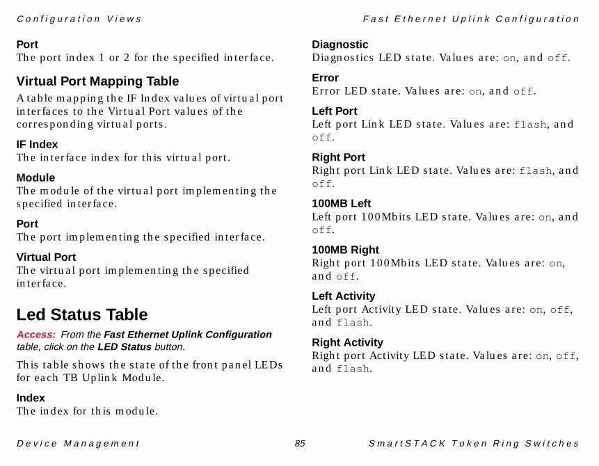
C o n f i g u r a t i o n V i e w s F a s t E t h e r n e t U p l i n k C o n f i g u r a t i o n
D e v i c e M a n a g e m e n t 85 S m a r t S T A C K T o k e n R i n g S w i t c h e s
PortThe port index 1 or 2 for the specified interface.
Virtual Port Mapping TableA table mapping the IF Index values of virtual port interfaces to the Virtual Port values of the corresponding virtual ports.
IF IndexThe interface index for this virtual port.
ModuleThe module of the virtual port implementing the specified interface.
PortThe port implementing the specified interface.
Virtual PortThe virtual port implementing the specified interface.
Led Status TableAccess: From the Fast Ethernet Uplink Configurationtable, click on the LED Status button.
This table shows the state of the front panel LEDs for each TB Uplink Module.
IndexThe index for this module.
DiagnosticDiagnostics LED state. Values are: on, and off .
ErrorError LED state. Values are: on, and off .
Left PortLeft port Link LED state. Values are: flash , and off .
Right PortRight port Link LED state. Values are: flash , and off .
100MB LeftLeft port 100Mbits LED state. Values are: on, and off .
100MB RightRight port 100Mbits LED state. Values are: on, and off .
Left ActivityLeft port Activity LED state. Values are: on, off , and flash .
Right ActivityRight port Activity LED state. Values are: on, off , and flash .

C o n f i g u r a t i o n V i e w s H S T R U p l i n k C o n f i g u r a t i o n T a b l e
D e v i c e M a n a g e m e n t 86 S m a r t S T A C K T o k e n R i n g S w i t c h e s
HSTR Uplink ConfigurationTableAccess: From the Icon Subviews menu, selectConfiguration .
This table contains information about hardware and software version numbers.
IndexThe module index selects the appropriate User Expansion Module (UEM, in this case a HSTR Uplink Module) in the switch stack. The module indices are assigned as follows:
Product IDA string containing the hardware product id.
HW VersionA string containing the hardware version.
HW ECO LevelA string containing the ECO update level.
HW Serial No.A string containing the hardware serial number.
SW Product IDA string containing the software product id.
SW VersionA string containing the software version.
SW ECO LevelA string containing the ECO update level.
Boot PromA string containing the Bootprom version number.
Opens the HSTR Port Configuration Table (Page 87).
Table 22: HSTR Uplink Module Indices
Module Description
hstrUplinkModuleIndex 1 Leftmost UEM in switch number 1
hstrUplinkModuleIndex 2 Rightmost UEM in switch number 1
hstrUplinkModuleIndex 3 Leftmost UEM in switch number 2
hstrUplinkModuleIndex 4 Rightmost UEM in switch number 2
hstrUplinkModuleIndex 16 Rightmost UEM in switch number 8
Port Configuration

C o n f i g u r a t i o n V i e w s H S T R U p l i n k C o n f i g u r a t i o n T a b l e
D e v i c e M a n a g e m e n t 87 S m a r t S T A C K T o k e n R i n g S w i t c h e s
Opens the HSTR Virtual Port Configuration Table (Page 89).
Opens the Message Logs View (Page 72). This view implements a buffer containing the last 10 log messages generated by the ATM Uplink.
Opens the Led Status Table (Page 85). This view shows the state of the front panel LEDs of each AUM.
HSTR Port Configuration TableAccess: From the HSTR Uplink Configuration table, clickon the Port Configuration button.
Index.PortIndex to identify port on module. Port 1 is the port to the left and port 2 is the port to the right.
IF IndexA pointer to the entry in the Interface Table corresponding to this port.
Tag ProtocolProtocol type for use in IEEE 802.1Q SNAP header.
Port ModePort operation mode. Values are: auto , fdx Port , and fdx-Station .
Act Port ModeThe actual port operation mode. If the port is in auto mode, this object will return the mode that the port opened in. Values are: fdx-Port , fdx-Station , and unknown .
Cfg Loss ThrNumber of configuration loss events during the sample period. If exceeded, the port will become disabled. If the port is disabled by this function the port must be manually re-enabled. When writing to Cfg Loss Thr or Cfg Loss, the configuration loss statistics, Cfg Loss E and Cfg Loss Last RC, will be reset.
Cfg LossThe sampling period, in minutes, for the port monitors to determine if the configuration loss threshold has been exceeded. When writing to Cfg Loss Thr or Cfg Loss, the configuration loss statistics, Cfg Loss E and Cfg Loss Last RC will be reset.
Virtual Port
Message Log
LED Status

C o n f i g u r a t i o n V i e w s H S T R U p l i n k C o n f i g u r a t i o n T a b l e
D e v i c e M a n a g e m e n t 88 S m a r t S T A C K T o k e n R i n g S w i t c h e s
Cfg Loss ENumber of events, as described in Cfg Loss Last RC, after the port has completed the join process and then lost communication. The configuration loss statistics will be reset, when writing to any of the two configuration variables.
Cfg Loss Last RCReason code describing the cause of the latest configuration loss. A value of no-cfg-loss will be returned when there has not been a configuration loss. The configuration loss statistics will be reset, when writing to either of the two configuration variables. See Table 19, Reason Codes (Page 78).
Aging LvlThreshold to demand age the port address table containing address entries for all virtual ports on this physical port. All numbers refer to percentage of the address table. The only values accepted by the agent are 50, 60, 70, 80, 90 and 0. Setting the value to 0 disables demand aging.
Trace MaskA 32 bit mask controlling log message output. Log messages are collected in the Message Log Table defined in the status section below.
StateProvides more information on the operational state of the HSTR port than what can otherwise be read from ifOperStatus. The states have the following semantics:
Table 23: HSTR Port Configuration State
State Description
unknown The port state is unknown.
disabled The port is administratively disabled.
down The port may now be configured. Once configured, it can be brought to the operational state up.
goingUp The port is coming into the operational state up.
up The port is operational and VPs can now be brought into their operational state thereby enabling traffic across the HSTR Uplink Module. This state maps to ifOperStatus "up". All other values of State map to ifOperStatus "down".
goingDown The port is being taken out of the operational state.
failing The port has failed. The message log may be inspected to find the cause of the failure.

C o n f i g u r a t i o n V i e w s H S T R U p l i n k C o n f i g u r a t i o n T a b l e
D e v i c e M a n a g e m e n t 89 S m a r t S T A C K T o k e n R i n g S w i t c h e s
Open the Port Mapping Information. This table maps the IF Index values of 100 Mbit TB interfaces to the Module and Port values of the corresponding TB ports.
Port Mapping InformationAccess: From either the HSTR Port Configuration table orthe HSTR Virtual Port Configuration table, click on thePort Mapping button.
This view contains two tables, Port Mapping and Virtual Port Mapping, described below.
Port MappingA table mapping the IF Index values of 100 Mbit HSTR interfaces to the Module and Port values of the corresponding HSTR ports.
IF IndexA pointer to the entry in the ifTable corresponding to this virtual port.
ModuleThe uplink module containing the physical port implementing the specified interface.
PortThe port number of the specified interface.
Virtual Port MappingA table mapping the IF Index values of virtual port interfaces to the Module, Port, and Virtual Port values of the corresponding virtual ports.
IF IndexA pointer to the entry in the ifTable corresponding to this virtual port.
ModuleThe Module of the virtual port implementing the specified interface.
PortThe port of the virtual port implementing the specified interface.
Virtual PortThe index of the virtual port implementing the specified interface.
HSTR Virtual Port ConfigurationTableAccess: From the HSTR Uplink Configuration table, clickon the Virtual Port button.
Index.Port.VPIdentifies a specific virtual port.
Port Mapping

C o n f i g u r a t i o n V i e w s H S T R U p l i n k C o n f i g u r a t i o n T a b l e
D e v i c e M a n a g e m e n t 90 S m a r t S T A C K T o k e n R i n g S w i t c h e s
IF IndexA pointer to the entry in the Interface Table corresponding to this virtual port.
Modify FCControls whether FC modification is enabled for this virtual port. Values are: disabled , and enabled .
Tagging ModeControls whether this virtual port uses VLAN tagging. Values are: tagged , and untagged .
TransmitMTU size of this virtual port. Values are: mtu1500 , mtu4472 , mtu8144 , mtu17800 , and useBRF.
Max ExploreExplorer frame forwarding rate per second throttle. A value of (-1 ) disables explorer frame throttling.
SpanningUsed when configuring manual spanning tree. Setting this object to forwarding or blocking overrides the spanning tree algorithm for this virtual port. Setting this object to auto turns the spanning tree algorithm on for this virtual port. Setting this object to unknown is not allowed.
Aging TimeAddress aging time in minutes. Setting this object to zero disables address aging.
Security ModeVirtual port security mode is used to disable address learning at a port where an allow-source or allow-destination MAC address filter is configured.
StateThe operational state of the virtual port (VP). The states have the following options:
Table 24: Virtual Port Security Mode
A value of: Indicates that...
normal The virtual port is not configured for security.
secure-src-addrs Learning for source addresses is disabled.
secure-dest-addrs Learning for destination addresses is disabled.
secure-src-and-dest-addrs Learning is disabled for both source and destination addresses.

C o n f i g u r a t i o n V i e w s H S T R U p l i n k C o n f i g u r a t i o n T a b l e
D e v i c e M a n a g e m e n t 91 S m a r t S T A C K T o k e n R i n g S w i t c h e s
Row StatusUsed to control creation and deletion of new rows in the table. Values are: active , notInService , notReady , createAndGo , createAndWait , and destroy .
Opens the Add Entry Virtual Port Entry.
Add Entry Virtual Port EntryAccess: From the HSTR Virtual Port ConfigurationTable , click on the Add Entry button.
From within this view, you can add entries into the HSTR Virtual Port Configuration Table (Page 89). Fields in this view correspond to the column headings in the HSTR Uplink Configuration Table.
Opens the Port Mapping Information (Page 89) table. This table maps the IF Index values of 100 Mbit TB interfaces to the Module and Port values of the corresponding TB ports.
LED Status TableAccess: From the Virtual Port Configuration Table, clickon the LED Status button.
Shows the state of the front panel LEDs of each HSTR Uplink Module. The status of the port activity LEDs are not shown though.
Table 25: HSTR Port Operational State
A value of: Indicates that...
unknown The VP state is unknown; the user should never see this.
down The VP is administratively disabled. It may now be configured. Once configured, it can be brought into one of its operational states.
up The VP is in operational state, but due to the spanning tree algorithm it is not forwarding frames, i.e. the VP is up but not forwarding. Forwarding is the "real" operational state.
forwarding The VP is in operational state, capable of forwarding frames.
dormant The VP is administratively enabled, but the physical port is not open (up).
Add Entry
Port Mapping

C o n f i g u r a t i o n V i e w s S i g n a l i n g C o n f i g u r a t i o n V i e w
D e v i c e M a n a g e m e n t 92 S m a r t S T A C K T o k e n R i n g S w i t c h e s
IndexThe module index selects the appropriate User Expansion Module (UEM, in this case a HSTR Uplink Module) in the switch stack. See Table 22, HSTR Uplink Module Indices (Page 86).
DiagnosticDiagnostics LED state. Values are: on, and off .
ErrorError LED state. Values are: on, and off .
Left PortLeft port Link LED state. Values are: on, off , and flash .
Right PortRight port Link LED state. Values are: on, off , and flash .
Signaling Configuration ViewAccess: From the Icon Subviews menu for the ATMULAppApplication icon, select Signaling .
This table contains configuration variables that control different properties of the physical ATM port.
IndexThe module index selects the appropriate ATM Uplink Module (AUM) in the switch stack. The
module’s indices are assigned in Table 16 (Page 66).
Max SVCThe maximum number of SVC calls/connections setup or clear operations that can be processed concurrently in the uplink.
T301 (CONNECT)The maximum time (in seconds) to wait for CONNECT after receiving ALERTING. Should be at least 3 minutes (180 seconds ).
T303 (SETUP)The maximum time (in seconds) to wait for response to SETUP (i.e. CALL_PROCEEDING, ALERTING or CONNECT).
T308 (RELEASE)The maximum time to wait for a response to RELEASE. Default value is 30.
T309 (SAAL)The maximum time (in seconds) allowing SAAL (SSCOP) connection loss. If SSCOP experiences connection loss for longer than this time for a signalling connection, the signalling instance will clear all its calls— active calls, as well as calls under establishment.

C o n f i g u r a t i o n V i e w s S i g n a l i n g C o n f i g u r a t i o n V i e w
D e v i c e M a n a g e m e n t 93 S m a r t S T A C K T o k e n R i n g S w i t c h e s
T310 (SETUP)The maximum time (in seconds) to wait for response to SETUP (i.e. ALERTING or CONNECT) after receiving CALL PROCEEDING.
T313 (CONNECT)The maximum time (in seconds) to wait for response to CONNECT.
T316 (RESTART)The maximum time (in seconds) to wait for response to RESTART.
T317 (RESTART)The maximum time (in seconds) to act on RESTART. This value should be less than T316 (RESTART).
T322 (STATUS)The maximum time (in seconds) to wait for response to STATUS ENQUIRY.
This button opens the SSCOP Configuration View.
SSCOP Configuration ViewAccess: From the Signaling Configuration view, selectthe SSCOP Configuration button.
This view contains the following fields:
IndexThe module index selects the appropriate ATM Uplink Module (AUM) in the switch stack. The module’s indices are assigned in Table 16 (Page 66).
Max Rcv WinThe maximum window size.
Max Con CtlThe maximum SSCOP Connection control state variable value.
Max Poll DataThe maximum number of data transmissions between polls.
Max StatThe maximum number of list elements placed in a SSCOP stat PDU.
Timer PollThe time (in seconds) between polling intervals.
Timer No ResThe time (in seconds) that it takes for one stat PDU to be received.
SSCOP Configuration

C o n f i g u r a t i o n V i e w s S T S 1 6 S t a c k C o n f i g u r a t i o n V i e w
D e v i c e M a n a g e m e n t 94 S m a r t S T A C K T o k e n R i n g S w i t c h e s
Timer Keep AliveThe time (in seconds) of the next polling.
Timer IdleThe time (in seconds) that the network is idle.
Timer CCDefines the maximum time (in units of 100 milliseconds) to wait for response, during outgoing link establish, release, resynch and recovery. Should be somewhat greater than a round-trip delay. Default is 1.
Max SduThe maximum SSCOP SDU size (SAAL Service Data Unit size) in bytes. Default is 4096 .
Max UuThe maximum SSCOP UU size (User-to-User data size) in bytes. Default is 4096 .
STS16 Stack ConfigurationViewAccess: From the Icon Subviews menu for the STS16AppApplication icon, select Configuration .
This view presents descriptive information regarding SmartSTACK configuration. The view provides access to a series of Read/Write and Read Only fields, in addition to four buttons at
the bottom of the panel. Field descriptions are as follows:
IP AddressThe IP address of the current TrBRF.
Subnet MaskThe subnet mask of the current TrBRF.
Default GatewayIP default gateway of the current TrBRF.
TFTP Server IPTFTP server's IP address.
BRF Server Conn.TrBRF to which the server is connected.
TFTP File Loc.Path and filename of the binary file on the server.
Download SwitchSetting this to any number between 1 and 8 starts a TFTP download for that box. Setting this to 9 starts a TFTP download for all boxes in a stack.
Download StatusReading complete from this object means the write to flash has succeeded and the switch is ready to be rebooted. Values are: writing , complete , and other .

C o n f i g u r a t i o n V i e w s S T S 1 6 S t a c k C o n f i g u r a t i o n V i e w
D e v i c e M a n a g e m e n t 95 S m a r t S T A C K T o k e n R i n g S w i t c h e s
Switch ConfigThe stack configuration of the system. A system can exist in three possible configurations.
1 Stand alone mode where the system has only one switch and is not connected to any other switches.
2 Back to Back mode in which a pair of switches are connected back to back through Stack Port.
3 Matrix mode in which the stack has up to eight switches connected to a Matrix through the Stack Port.
Stack StatusStack status indicates if the stack is going through the Stack Management Update protocol. Management stations should check this status if they receive a genErr on a SET request for any of the stack wide attributes. Values are running and updating .
Number SwitchesTotal number of switches in the stack.
SysLog Deamon IPSyslog daemon's IP address.
BRF Deamon Conn.TrBRF to which the syslog daemon is connected.
SysLog FacilityFacility code to be sent to syslog daemon.
SysLog MaskMask defining the types of messages which should be sent to syslog daemon.
Number Matrix ModNumber of Matrix modules in the stack. This object is set to zero if the switch is not connected to a Matrix.
Matrix StatusStatus of the Active Matrix module in the stack. This object is set to none if the switch is not connected to a Matrix. Values are: primary , secondary , none , and failed .
Max MTU SizeMax MTU size currently supported by the stack. Either mtu4472 or mtu17800 will be returned. Other values are: mtu1500 , mtu8144 , anduseBRF.
RMON State ConfThis object reflects the configured RMON state. Values are: enabled and disabled .
RMON State ActualThis object reflects the actual RMON state. Values are: enabled and disabled .

C o n f i g u r a t i o n V i e w s S T S 1 6 S t a c k C o n f i g u r a t i o n V i e w
D e v i c e M a n a g e m e n t 96 S m a r t S T A C K T o k e n R i n g S w i t c h e s
SNMP CapabilitiesThis object reflects the SNMP capabilities of the switch.
Current TimeCurrent time of the switch. To set the time use the format yyyy mm dd hh mm ss. All fields are required. Setting this object will set the time in all the switches in the stack to the new value.
The following four buttons are located at the bottom of the STS Stack Configuration view:
This button accesses the Trap Receiver Information View, which provides information for each trap received.
This button accesses the Switch Stack Configuration View (Page 97), providing the current configuration of the stack. It also provides a mapping of Switch Numbers to their addresses. The Management Application is required to retrieve this table and verify its own view of the stack periodically and/or when it receives a trap indicating a change in the stack configuration.
This button accesses the Switch Module Information View (Page 99), which displays the module configuration information for each switch, and each module.
This button provides access to a table displaying configuration information about each port. See Port Configuration View (Page 101).
Trap Receiver Information ViewAccess: In the STS16 Stack Configuration view, click theTrap Receiver button.
The following column headings and button appear in the Trap Receiver Information View:
IndexTrap receiver index for each entry.
StatusValues are: other - none of the following, valid- a valid entry, invalid - an invalid entry, and create - create row. Setting the value to invalid deletes the row from the table. The value, invalid, should never be returned on a GET. Setting this value to create causes a new row to
Trap Receiver
Stack Info
Module Info
Port Info

C o n f i g u r a t i o n V i e w s S T S 1 6 S t a c k C o n f i g u r a t i o n V i e w
D e v i c e M a n a g e m e n t 97 S m a r t S T A C K T o k e n R i n g S w i t c h e s
be created if the row does not already exist. To create a new row, set the Status to create and the Index to any valid index which does not already exist. The value returned on GETs should be valid or other, which is used to indicate any other condition.
IP AddressIP address for an SNMP manager that is to receive the trap.
Community NameCommunity string to use in outgoing traps.
TrBRF Traps OnTrBRFs on which traps are sent to this target. Each octet within the value of this object specifies a set of eight TrBRFs, with the first octet specifying TrBRFs 1 through 8, the second octet specifying TrBRFs 9 through 16, etc. Within each octet, the most significant bit represents the lowest numbered TrBRF, and the least significant bit represents the highest numbered TrBRF. Thus, each TrBRF of the stack is represented by a single bit within the value of this object. If that bit has a value of 1, then that TrBRF is included in the set of TrBRFs sending traps. The TrBRF is not included if its bit has a value of 0. The default is all zeros. Reading all of the entries in the Switch Stack Table will give the possible valid bits
that can be set. A value of all FF's will enable traps on all configured TrBRFs.
At the bottom of the Trap Receiver Information view, is the following button:
The Add Entry button accesses the Add Trap Receiver Table Entry View.
Add Trap Receiver Table Entry ViewAccess: From the Trap Receiver Information view, clickthe Add Entry button.
From within this view, you can add new entries to the Trap Receiver Information View (Page 96). Fields in this view correspond to the column headings in the Trap Receiver Information View.
Switch Stack Configuration ViewAccess: In the STS16 Stack Configuration view, click theStack Info button.
This view displays standard Sort, Find, Update and Print buttons (see SPECTRUM Views) and column headings with the following application-specific configuration information:
Add Entry
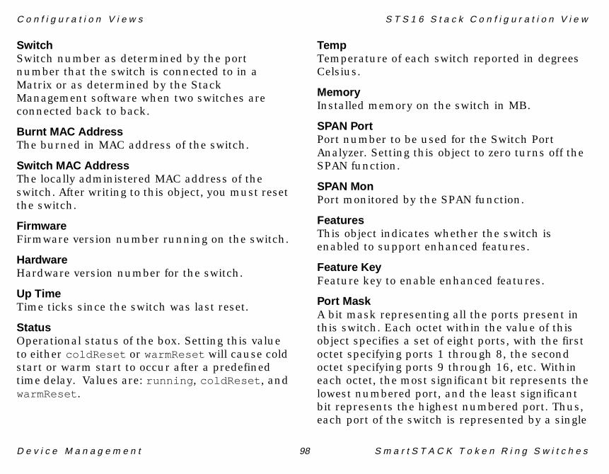
C o n f i g u r a t i o n V i e w s S T S 1 6 S t a c k C o n f i g u r a t i o n V i e w
D e v i c e M a n a g e m e n t 98 S m a r t S T A C K T o k e n R i n g S w i t c h e s
SwitchSwitch number as determined by the port number that the switch is connected to in a Matrix or as determined by the Stack Management software when two switches are connected back to back.
Burnt MAC AddressThe burned in MAC address of the switch.
Switch MAC AddressThe locally administered MAC address of the switch. After writing to this object, you must reset the switch.
FirmwareFirmware version number running on the switch.
HardwareHardware version number for the switch.
Up TimeTime ticks since the switch was last reset.
StatusOperational status of the box. Setting this value to either coldReset or warmReset will cause cold start or warm start to occur after a predefined time delay. Values are: running , coldReset , and warmReset .
TempTemperature of each switch reported in degrees Celsius.
MemoryInstalled memory on the switch in MB.
SPAN PortPort number to be used for the Switch Port Analyzer. Setting this object to zero turns off the SPAN function.
SPAN MonPort monitored by the SPAN function.
FeaturesThis object indicates whether the switch is enabled to support enhanced features.
Feature KeyFeature key to enable enhanced features.
Port MaskA bit mask representing all the ports present in this switch. Each octet within the value of this object specifies a set of eight ports, with the first octet specifying ports 1 through 8, the second octet specifying ports 9 through 16, etc. Within each octet, the most significant bit represents the lowest numbered port, and the least significant bit represents the highest numbered port. Thus, each port of the switch is represented by a single

C o n f i g u r a t i o n V i e w s S T S 1 6 S t a c k C o n f i g u r a t i o n V i e w
D e v i c e M a n a g e m e n t 99 S m a r t S T A C K T o k e n R i n g S w i t c h e s
bit within the value of this object. If that bit has a value of 1, then that port is included in the set of ports in this switch; the port is not included in this switch if its bit has a value of 0.
AgingAging time in minutes for the master address table entries on this switch.
Age LevelThreshold to demand age the master address table. All numbers refer to percentage of the address table. The only values accepted by the agent are 50, 60, 70, 80, 90 and 0. Setting the value to 0 disables demand aging.
Object IDThe object ID used to uniquely identify the type of token ring switch.
Error LEDThe state of the error LED. Values are: on, off , and flash .
Diag LEDThe state of the diagnostic LED. Values are: on, off , and flash .
TrCRFs SPAN MonitoredTrCRFs for which traffic on the port specified by SPAN Monitored port should be monitored. Individual TrCRFs can be selected for monitoring
only on trunk ports. Each octet within the value of this object specifies a set of eight TrCRFs, with the first octet specifying TrCRFs 1 through 8, the second octet specifying TrCRFs 9 through 16, etc. Within each octet, the most significant bit represents the lowest numbered TrCRF, and the least significant bit represents the highest numbered TrCRF. Thus, each TrCRF of the stack is represented by a single bit within the value of this object. If that bit has a value of 1, then that TrCRF is included in the set of TrCRFs for which traffic should be monitored; the TrCRF is not included if its bit has a value of 0. The default is all zeros. Get requests for this object will return all zeros if the SPAN monitored port specifies a non-trunk port. Set requests for this object will be rejected with a "badValue" error if the SPAN monitored port specifies a non-trunk port.
Switch Module Information ViewAccess: In the STS16 Stack Configuration view, click theModule Info button.
The Module Number Table in the Switch Module Information view displays the following column headings:
SwitchSwitch number as determined by the port number that the switch is connected to in a
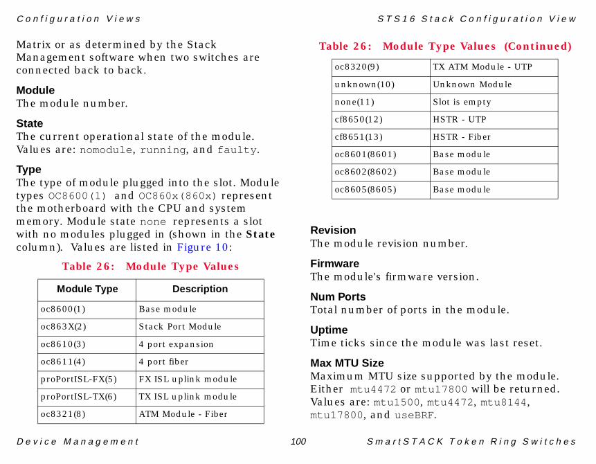
C o n f i g u r a t i o n V i e w s S T S 1 6 S t a c k C o n f i g u r a t i o n V i e w
D e v i c e M a n a g e m e n t 100 S m a r t S T A C K T o k e n R i n g S w i t c h e s
Matrix or as determined by the Stack Management software when two switches are connected back to back.
ModuleThe module number.
StateThe current operational state of the module. Values are: nomodule , running , and faulty .
TypeThe type of module plugged into the slot. Module types OC8600(1) and OC860x(860x) represent the motherboard with the CPU and system memory. Module state none represents a slot with no modules plugged in (shown in the State column). Values are listed in Figure 10:
RevisionThe module revision number.
FirmwareThe module's firmware version.
Num PortsTotal number of ports in the module.
UptimeTime ticks since the module was last reset.
Max MTU SizeMaximum MTU size supported by the module. Either mtu4472 or mtu17800 will be returned. Values are: mtu1500 , mtu4472 , mtu8144 ,mtu17800 , and useBRF.
Table 26: Module Type Values
Module Type Description
oc8600(1) Base module
oc863X(2) Stack Port Module
oc8610(3) 4 port expansion
oc8611(4) 4 port fiber
proPortISL-FX(5) FX ISL uplink module
proPortISL-TX(6) TX ISL uplink module
oc8321(8) ATM Module - Fiber
oc8320(9) TX ATM Module - UTP
unknown(10) Unknown Module
none(11) Slot is empty
cf8650(12) HSTR - UTP
cf8651(13) HSTR - Fiber
oc8601(8601) Base module
oc8602(8602) Base module
oc8605(8605) Base module
Table 26: Module Type Values (Continued)

C o n f i g u r a t i o n V i e w s S T S 1 6 S t a c k C o n f i g u r a t i o n V i e w
D e v i c e M a n a g e m e n t 101 S m a r t S T A C K T o k e n R i n g S w i t c h e s
Port Configuration ViewAccess: In the STS16 Stack Configuration view, click thePort Info button.
The Port Configuration Table in the Port Configuration view displays standard Sort, Find, Update and Print buttons (see SPECTRUM Views) and the following column headings:
Switch.PortA unique value for each port entry. The value corresponds to the port number.
ModuleNumber of the module that contains this port.
If IndexA pointer to the entry in the Interface Table corresponding to this port.
Reset CtrsSetting this object to reset causes all traffic counters for this port to be set to zero. Also the value of Port Statistics Reset Timer is set to zero. Values are: other - none of the following, running - port is functioning, and reset - reset port counters.
Reset AddrsSetting this object to reset clears all address table entries for this port as well as setting all port traffic counters to zero and setting Port Statistics
Reset Timer to zero. Values are: other - none of the following, running - port is functioning, and reset - clear address table and reset port counters.
Addr AgeingPort level address aging time in minutes. Setting this object to zero disables address aging.
Demand AgeingThreshold to demand age the port address table. All numbers refer to percentage of the address table. The only values accepted by the agent are 50, 60, 70, 80, 90 and 0. Setting the value to 0 disables demand aging.
Low Error ThresLower error rate threshold which causes the port to transition from store and forward mode to cut-through mode.
High Error ThresUpper error rate threshold which causes the port to transition from cut-through mode to store and forward mode.
Error SamplingError sampling interval in minutes.
Max TransmitMTU size of this port. Values are: mtu1500 , mtu4472 , mtu8144 , and mtu17800 .

C o n f i g u r a t i o n V i e w s S T S 1 6 S t a c k C o n f i g u r a t i o n V i e w
D e v i c e M a n a g e m e n t 102 S m a r t S T A C K T o k e n R i n g S w i t c h e s
Max ExplorerExplorer frame forwarding rate per second throttle. A value of (-1 ) disables explorer frame throttling.
Set AC BitsSpecifies if the AC bits shall be set unconditionally when a port forwards certain LLC frames. Values are: enabled , and disabled .
Early Tkn RlsEarly token release operation. Values are: enabled , and disabled .
Forwarding ModeOperational frame switching mode for the port. When in auto mode the port uses the Direct Cut algorithm to place the port in either cutthru or storeandforward mode. Values are: auto ,storeandforward , cutthru , and unknown .
Actual Fwd ModeActual operational frame switching mode for the port. Values are: storeandforward , cutthru , and unknown .
ModuleNumber of the module that contains this port.
Priority ThresThe highest token-ring frame priority that shall go to the low-priority transmit queue.
Xmit PriorityThe minimum token priority that will be used for transmit.
Cfg Loss ThresNumber of configuration loss events during the sample period which, if exceeded, should cause the port to be disabled. If the port is disabled by this function the port must be manually re-enabled.
CFG Loss IntThe sampling period, in minutes, for the port monitors to determine if the configuration loss threshold has been exceeded.
Bcast SupprThe number of broadcast frames per second allowed to be forwarded by this port. Any broadcast frames exceeding this watermark will not be forwarded by the port. Setting this object to 0 turns broadcast suppression off.
Time to LiveThe advertised time-to-live parameter on all CDP messages generated by the switch on this port.
Spanning TreeUsed when configuring a manual spanning tree. Setting this object to forwarding or blocking overrides the TrCRF's spanning tree's algorithm

C o n f i g u r a t i o n V i e w s S T S 1 6 S t a c k C o n f i g u r a t i o n V i e w
D e v i c e M a n a g e m e n t 103 S m a r t S T A C K T o k e n R i n g S w i t c h e s
for this port. Values are: auto , forwarding , blocking , and unknown .
SecurityPort security mode is used to disable address learning at a port where an allow-source or allow-destination MAC address filter is configured. A value of normal indicates that the port is not configured for security. A value of secure-src-addrs indicates that learning for source addresses is disabled. A value of secure-dest-addrs indicates that learning for destination addresses is disabled. A value of secure-src-and-dest-addrs indicates that learning is disabled for both source and destination addresses.
LEDThe state of the Link LED. Values are: on, off , and flash .
Operation ModePort operational mode. Values are: auto , port , station , ri-ro , passive-probe , and unknown ..
Actual OperThe actual port operational mode. If the port is in "auto mode," this object will return the mode in which the port opened. Values are: port , station , ri-ro , passive-probe , and unknown .
DuplexDuplex mode. The port could either be auto detected or forced to HDX or FDX. Values are: auto , hdx , fdx , none , and unknown .
Actual DuplexThe actual port duplex mode. If the port is in auto mode, this object will return the mode in which the port opened. Values are: hdx , fdx , none , and unknown .
RPS OperRing Parameter Server (RPS) operation. Values are: enabled , and disabled .
NameLogical port name.Note:Note:
Passive-probe mode can not be set with this object. The passive-probe mode is set automatically when a passive probe is defined in the Passive Probe Table.
Note:Note:
In Operation Mode, ri-ro is only valid for ports 19, 20, and ports on a fiber module.

C o n f i g u r a t i o n V i e w s P r o b e / C r o s s l i n k C o n f i g u r a t i o n V i e w
D e v i c e M a n a g e m e n t 104 S m a r t S T A C K T o k e n R i n g S w i t c h e s
Probe/Crosslink ConfigurationViewAccess: From the Icon Subviews menu for the STS16AppApplication icon, select Probe/Crosslink .
The Probe/Crosslink Configuration view displays two tables: Passive Probe Table and Crosslink Table (Page 105). Both tables have standard Sort, Find, Update and Print buttons (see SPECTRUM Views).
Passive Probe TableThis table allows you to view and configure passive probe ports.
Switch.IndexIndex into the Passive Probe Table. Table 12 describes the configuration options for the Passive Probe Table. The Port Mode column represents the operational mode of the Mon. Port. Set the objects in this table according to how you want to monitor the traffic.
PortThe port that is configured to mirror traffic from another port in the switch. This is the port to which you can connect an RMON probe. Setting this object to zero turns off the passive probe.
Mon. PortThe port that will have its traffic mirrored onto the probe port. Set this object to a non-zero value to have that port's traffic copied to the monitoring port. The default value is 0.
DirectionDirection of traffic flow that is being monitored. Values are: transmit - FDX ports only, receive- FDX ports only, both - HDX ports only, and unknown .
Table 27: Configuration Options
Index Port Mode Probe Direction
1 HDX both
1 FDX receive
2 HDX both
2 FDX transmit

C o n f i g u r a t i o n V i e w s T r C R F C o n f i g u r a t i o n V i e w
D e v i c e M a n a g e m e n t 105 S m a r t S T A C K T o k e n R i n g S w i t c h e s
Crosslink TableThis table allows you to view which ports are active in a particular crosslink.
SwitchSwitch number determined by the port number that the switch is connected to in a matrix or as determined by the Stack Management software when two switches are connected back to back.
NumberThe unique identifier for this row. Corresponds to the crosslink number.
Crosslink PortsA read-write field which defines the set of ports in this switch which are active in this crosslink. Each octet within the value of this object specifies a set of eight ports, with the first octet specifying ports 1 through 8, the second octet specifying ports 9 through 16, etc. Within each octet, the most significant bit represents the lowest numbered port, and the least significant bit represents the highest numbered port. Thus, each port of the switch is represented by a single bit within the value of this object. If that bit has a value of "1" then that port is included in the set of ports; the port is not included if its bit has a value of "0." Set requests containing "1" values in one or more bit positions which do not have a "1" value
in the corresponding position in the Port Mask (Page 32) column will fail with a badValue error. The maximum number of ports in a CrossLink and therefore the maximum number of bits in this object containing "1" values is 8.
TrCRF Configuration ViewAccess: From the Icon Subviews menu for the STS16AppApplication icon, select CRF Configuration .
This view supports dynamic configuration of Token Ring Concentrator Relay Functions (TrCRFs). There are eight column headings in the TrCRF Configuration Table. Double-click any value beneath a column heading to access the TrCRF Configuration Table Entry (Page 107) view, in which you can enter new configuration information.
TrCRF Configuration TableFrom within this table, you can choose a spanning tree protocol, select parameters for forwarding delay, hello time and max age, and configure manual spanning tree.
CRF No.Unique identifier for this entry in the TrCRF table. Corresponds to the TrCRF number.

C o n f i g u r a t i o n V i e w s T r C R F C o n f i g u r a t i o n V i e w
D e v i c e M a n a g e m e n t 106 S m a r t S T A C K T o k e n R i n g S w i t c h e s
NameUser defined name of the TrCRF.
ProtocolThe Spanning Tree Protocol to run on this TrCRF. Values are: none , cisco , and ieee .
Fwd DelayThe value used as the Forwarding Delay in this TrCRF. The range for this parameter is 400 to 3000 and is related to the value of Bridge Hello Max. Age (Page 34). The granularity of this timer is specified to be 1/100 of a second. This agent will return a “badValue” error if a set is attempted to a value which is not a whole number of seconds.
Hello TimeThe value to be used as the Hello Time in this TrCRF. The range for this parameter is 100 to 1000 . The granularity of this timer is specified to be 1/100 of a second. This agent will return a "badValue" error if a set is attempted to a value which is not a whole number of seconds.
Max AgThe value to be used as the Max Age in this TrCRF. The range for this parameter is 600 to 4000 and is related to the value of Bridge Hello Time (Page 34). The granularity of this timer is specified to be 1/100 of a second. This agent will
return a "badValue" error if a set is attempted to a value which is not a whole number of seconds.
Port ModeUsed when configuring manual spanning tree. Setting this object to forwarding or blocking overrides the spanning tree’s algorithm for TrCRF’s logical internal port that connects it to the TrBRF. Values are: auto , forwarding , and blocking .
Domain No.Internal unique identifier for this entry in the TrCRF table.
Beneath the TrCRF Configuration Table, there are two fields:
TrCRF ConfigurationA string of octets containing one bit per TrCRF in the management domain. The first octet corresponds to TrCRFs with CRF No. 1 through 8; the second octet to TrCRFs 9 through 16; etc. The most significant bit of each octet corresponds to the lowest value CRF No. in that octet. If the bit corresponding to a TrCRF is set to "1," then the TrCRF is a transited configured TrCRF on the local device. (Default TrCRFs which must transit the local device are always considered to be "transited configured TrCRFs".) Any attempt to set a bit string which: (a) has more bits set than the local device can transit; (b) does not have all

C o n f i g u r a t i o n V i e w s T r B R F C o n f i g u r a t i o n V i e w
D e v i c e M a n a g e m e n t 107 S m a r t S T A C K T o k e n R i n g S w i t c h e s
bits set corresponding to default TrCRFs which must transit the device; or (c) corresponds to non-existent TrCRFs (TrCRFs whose IDs are not defined in the management domain), will be rejected with a "badValue" error.
TrCRFs in DomainA string of octets containing one bit per TrCRF in the management domain. The first octet corresponds to TrCRFs with CRF No. 1 through 8; the second octet to TrCRFs 9 through 16; etc. The most significant bit of each octet corresponds to the lowest value CRF No. in that octet. If the bit corresponding to a TrCRF is set to "1," then the TrCRF transits the local device either because it was configured to or because it was selected to automatically by the selection algorithm.
TrCRF Configuration Table EntryThe fields in this table correspond to those in the TrCRF Configuration View (Page 105). Field names may differ slightly from column headings (i.e.: Port Mode = Internal Mode, Domain No. = Identifier), but the attributes remain the same.
TrBRF Configuration ViewAccess: From the Icon Subviews menu for the STS16AppApplication icon, select BRF Configuration .
BRF No.Unique identifier for this entry in the TrBRF table. Corresponds to the TrBRF number.
NameUser defined name of the TrBRF.
IP StateIP configuration for this TrBRF. Values are: ip-disabled , bootp-when-needed , and bootp-always .
IP AddressIP Address assigned to this TrBRF. Changes to the IP Address of the TrBRF to which the management station belongs causes loss of connectivity until the management station updates its information about the IP Address.
Subnet MaskThe subnet mask for this TrBRF.
Dflt GatewayThe IP Address of the default gateway for this TrBRF.
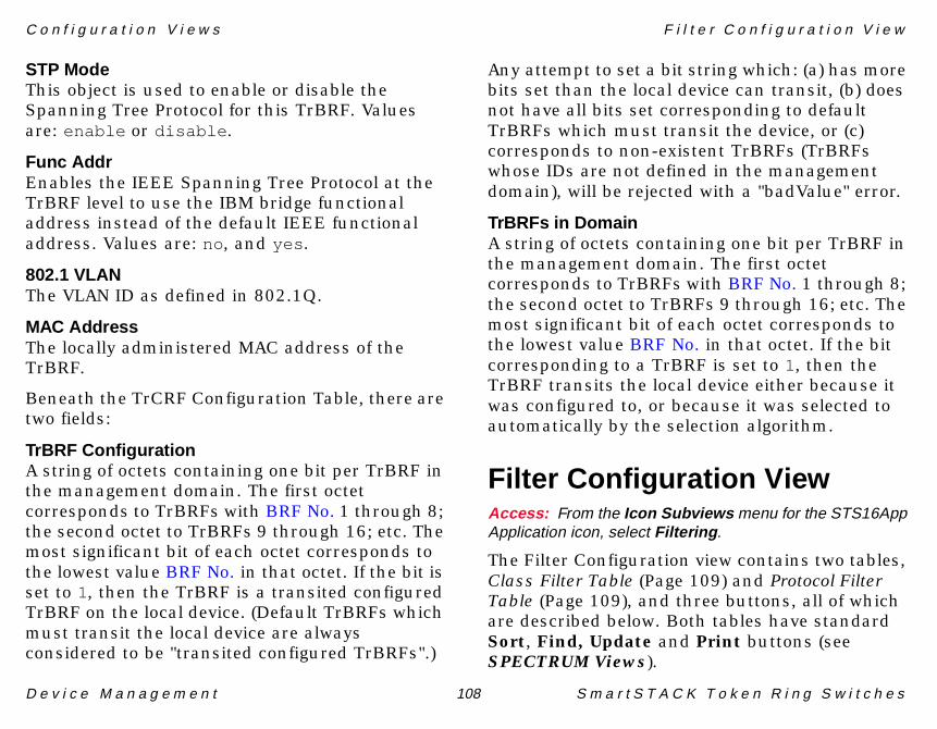
C o n f i g u r a t i o n V i e w s F i l t e r C o n f i g u r a t i o n V i e w
D e v i c e M a n a g e m e n t 108 S m a r t S T A C K T o k e n R i n g S w i t c h e s
STP ModeThis object is used to enable or disable the Spanning Tree Protocol for this TrBRF. Values are: enable or disable .
Func AddrEnables the IEEE Spanning Tree Protocol at the TrBRF level to use the IBM bridge functional address instead of the default IEEE functional address. Values are: no, and yes .
802.1 VLANThe VLAN ID as defined in 802.1Q.
MAC AddressThe locally administered MAC address of the TrBRF.
Beneath the TrCRF Configuration Table, there are two fields:
TrBRF ConfigurationA string of octets containing one bit per TrBRF in the management domain. The first octet corresponds to TrBRFs with BRF No. 1 through 8; the second octet to TrBRFs 9 through 16; etc. The most significant bit of each octet corresponds to the lowest value BRF No. in that octet. If the bit is set to 1, then the TrBRF is a transited configured TrBRF on the local device. (Default TrBRFs which must transit the local device are always considered to be "transited configured TrBRFs".)
Any attempt to set a bit string which: (a) has more bits set than the local device can transit, (b) does not have all bits set corresponding to default TrBRFs which must transit the device, or (c) corresponds to non-existent TrBRFs (TrBRFs whose IDs are not defined in the management domain), will be rejected with a "badValue" error.
TrBRFs in DomainA string of octets containing one bit per TrBRF in the management domain. The first octet corresponds to TrBRFs with BRF No. 1 through 8; the second octet to TrBRFs 9 through 16; etc. The most significant bit of each octet corresponds to the lowest value BRF No. in that octet. If the bit corresponding to a TrBRF is set to 1, then the TrBRF transits the local device either because it was configured to, or because it was selected to automatically by the selection algorithm.
Filter Configuration ViewAccess: From the Icon Subviews menu for the STS16AppApplication icon, select Filtering .
The Filter Configuration view contains two tables, Class Filter Table (Page 109) and Protocol Filter Table (Page 109), and three buttons, all of which are described below. Both tables have standard Sort, Find, Update and Print buttons (see SPECTRUM Views).
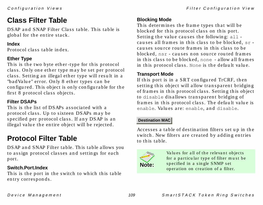
C o n f i g u r a t i o n V i e w s F i l t e r C o n f i g u r a t i o n V i e w
D e v i c e M a n a g e m e n t 109 S m a r t S T A C K T o k e n R i n g S w i t c h e s
Class Filter TableDSAP and SNAP Filter Class table. This table is global for the entire stack.
IndexProtocol class table index.
Ether TypeThis is the two byte ether-type for this protocol class. Only one ether type may be set per protocol class. Setting an illegal ether type will result in a "badValue" error. Only 8 ether types can be configured. This object is only configurable for the first 8 protocol class objects.
Filter DSAPsThis is the list of DSAPs associated with a protocol class. Up to sixteen DSAPs may be specified per protocol class. If any DSAP is an illegal value the entire object will be rejected.
Protocol Filter TableDSAP and SNAP Filter table. This table allows you to assign protocol classes and settings for each port.
Switch.Port.IndexThis is the port in the switch to which this table entry corresponds.
Blocking ModeThis determines the frame types that will be blocked for this protocol class on this port. Setting the value causes the following: all - causes all frames in this class to be blocked, sr - causes source route frames in this class to be blocked, nsr - causes non source routed frames in this class to be blocked, none - allow all frames in this protocol class. None is the default value.
Transport ModeIf this port is in a SRT configured TrCRF, then setting this object will allow transparent bridging of frames in this protocol class. Setting this object to disable disallows transparent bridging of frames in this protocol class. The default value is enable . Values are: enable , and disable .
Accesses a table of destination filters set up in the switch. New filters are created by adding entries to this table.
Destination MAC
Note:Note:
Values for all of the relevant objects for a particular type of filter must be specified in a single SNMP set operation on creation of a filter.

C o n f i g u r a t i o n V i e w s F i l t e r C o n f i g u r a t i o n V i e w
D e v i c e M a n a g e m e n t 110 S m a r t S T A C K T o k e n R i n g S w i t c h e s
Set operations which do not contain all of the required objects for a given filter type will fail with an error-status of "genErr". The objects required for each filter type are described in the Table 28 table:
Since the indices for the MAC Destination Table are switch number, MAC address, and filter type, the instance information for a given object specifies which filter is being created.
This button accesses the Destination MAC Filter (Page 111) view.
A table of source filters set up in the switch. New filters are created by adding entries to this table.
Set operations which do not contain all of the required objects for a given filter type will fail with an error-status of "genErr". The objects required for each filter type are as follows:
Since the indices for the Source MAC Filter table are switch number, MAC address, and filter type, the instance information for a given object specifies which filter is being created.
This button accesses the Source MAC Filter (Page 112) view.
This button accesses the Duplicate/Trunk Configuration (Page 114) view. This view displays
Table 28: Destination Filters
MAC DestinationFilter Types
Required Objects for Creation
block-dest sts16MACDestFilterPortsallow-dest sts16MACDestFilterPortslimited-multicast sts16MACDestFilterPorts
sts16MACDestFilterExitMaskforce-dest sts16MACDestFilterPorts
sts16MACDestFilterRemoteBoxsts16MACDestFilterRemotePort
Source MAC
Note:Note:
Values for all of the relevant objects for a particular type of filter must be specified in a single SNMP set operation on creation of a filter.
Table 29: Source Filters
Source Filter Types Required Objects for Creation
block-src sts16MACSourceFilterPorts
allow-src sts16MACSourceFilterPorts
Duplicate Address/Trunk Protocol

C o n f i g u r a t i o n V i e w s F i l t e r C o n f i g u r a t i o n V i e w
D e v i c e M a n a g e m e n t 111 S m a r t S T A C K T o k e n R i n g S w i t c h e s
duplicate MAC addresses and allows you to assign protocol classes and settings for each trunk port.
Destination MAC FilterAccess: From the Filter Configuration view, select theDestination MAC button.
This table provides destination filters set up in the switch. New filters are created by adding entries to this table. This view contains the MAC Destination Table which has standard Sort, Find, Update, Print and Add Entry buttons (see SPECTRUM Views), as well as the following column headings:
SwitchThe port number to which the switch is connected in a Matrix, or as determined by the Stack Management software when two switches are connected back to back.
Dest MAC AddressThe destination MAC address in a frame to which this entry’s filtering information applies.
TypeThere are four types of destination MAC address filters (see Destination Filters (Page 110)):
1 Block destination address at specific ports- block-dest . This filter indicates that the specified ports must not send frames to the specified destination station address.
2 Allow destination address at specific ports- allow-dest . This filter indicates that the specified ports must send frames to the specified destination stations only.
3 Limited Multicast of address on filtered port(s) to specified exit mask of ports- limited-multicast .
4 Force destination address to specific ports- force-dest . This filter may be used for two purposes: to allow forwarding to a unicast address that has not been learned, or to limit forwarding of a multicast address to certain ports.
Port ListThe set of ports to which this filter is applied. Each octet within the value of this object specifies a set of eight ports, with the first octet specifying ports 1 through 8, the second octet specifying
Note:Note:
The Force Destination filter will only be applied to NSR frames.

C o n f i g u r a t i o n V i e w s F i l t e r C o n f i g u r a t i o n V i e w
D e v i c e M a n a g e m e n t 112 S m a r t S T A C K T o k e n R i n g S w i t c h e s
ports 9 through 16, etc. Within each octet, the most significant bit represents the lowest numbered port, and the least significant bit represents the highest numbered port. Thus, each port of the switch is represented by a single bit within the value of this object. If that bit has a value of 1, then that port is included in the set of ports; the port is not included if its bit has a value of 0.
Exit MaskThe set of output ports to which a limited multicast filter is applied. This object only has a value for Limited Multicast filters. Each octet within the value of this object specifies a set of eight ports, with the first octet specifying ports 1 through 8, the second octet specifying ports 9 through 16, etc. Within each octet, the most significant bit represents the lowest numbered port, and the least significant bit represents the highest numbered port. Thus, each port of the switch is represented by a single bit within the value of this object. If that bit has a value of 1 then that port is included in the set of ports; the port is not included if its bit has a value of 0.
Remote BoxThe remote switch to be used for a force destination filter.
Remote PortThe remote port to be used for a force destination filter.
StatusA get request always returns valid . Set this object to invalid to delete an entry.
Opens the Add Destination MAC Table Entry view.
Add Destination MAC Table EntryAccess: From the Destination MAC Filter table, click onthe Add Entry button.
From within this view, you can add entries into the Destination MAC Filter (Page 111). Fields in this view correspond to the column headings in the Destination MAC Filter Table.
Source MAC FilterAccess: From the Filter Configuration View , click on theSource MAC .
This table contains source filters set up in the switch. New filters are created by adding entries to this table. This view provides access to the MAC Source Table which has standard Sort,
Add Entry
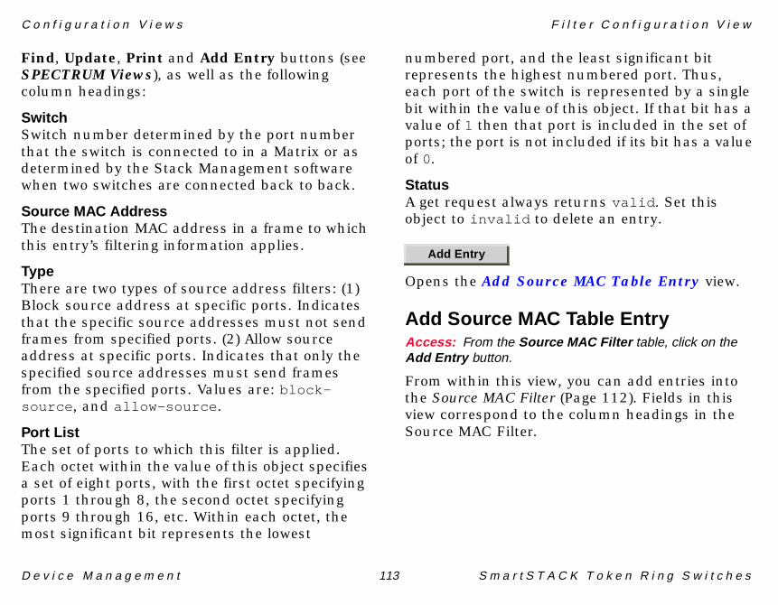
C o n f i g u r a t i o n V i e w s F i l t e r C o n f i g u r a t i o n V i e w
D e v i c e M a n a g e m e n t 113 S m a r t S T A C K T o k e n R i n g S w i t c h e s
Find, Update, Print and Add Entry buttons (see SPECTRUM Views), as well as the following column headings:
SwitchSwitch number determined by the port number that the switch is connected to in a Matrix or as determined by the Stack Management software when two switches are connected back to back.
Source MAC AddressThe destination MAC address in a frame to which this entry’s filtering information applies.
TypeThere are two types of source address filters: (1) Block source address at specific ports. Indicates that the specific source addresses must not send frames from specified ports. (2) Allow source address at specific ports. Indicates that only the specified source addresses must send frames from the specified ports. Values are: block-source , and allow-source .
Port ListThe set of ports to which this filter is applied. Each octet within the value of this object specifies a set of eight ports, with the first octet specifying ports 1 through 8, the second octet specifying ports 9 through 16, etc. Within each octet, the most significant bit represents the lowest
numbered port, and the least significant bit represents the highest numbered port. Thus, each port of the switch is represented by a single bit within the value of this object. If that bit has a value of 1 then that port is included in the set of ports; the port is not included if its bit has a value of 0.
StatusA get request always returns valid . Set this object to invalid to delete an entry.
Opens the Add Source MAC Table Entry view.
Add Source MAC Table EntryAccess: From the Source MAC Filter table, click on theAdd Entry button.
From within this view, you can add entries into the Source MAC Filter (Page 112). Fields in this view correspond to the column headings in the Source MAC Filter.
Add Entry

C o n f i g u r a t i o n V i e w s F i l t e r C o n f i g u r a t i o n V i e w
D e v i c e M a n a g e m e n t 114 S m a r t S T A C K T o k e n R i n g S w i t c h e s
Duplicate/Trunk ConfigurationAccess: From the Filter Configuration View , click on theDuplicate Address Trunk Protocol button.
This view provides access to two tables: Duplicate Address, and Trunk Protocol Table. Both tables have standard Sort, Find, Update, and Print buttons (see SPECTRUM Views), as well as the following column headings:
Duplicate AddressA table of MAC addresses that have been identified as duplicates within an address scope.
SwitchThe port number to which the switch is connected in a Matrix or as determined by the Stack Management software when two switches are connected back to back.
MAC AddressThe MAC address identified as being a duplicate. All frames having this MAC address as their source address are being discarded at the ports specified in the Port List.
Port ListA bit mask representing all the ports on which this duplicate MAC address is currently being filtered. Each octet within the value of this object
specifies a set of eight ports, with the first octet specifying ports 1 through 8, the second octet specifying ports 9 through 16, etc. Within each octet, the most significant bit represents the lowest numbered port, and the least significant bit represents the highest numbered port. Thus, each port of the switch is represented by a single bit within the value of this object. If that bit has a value of 1 then that port is included in the set of ports in this switch; the port is not included in this switch if its bit has a value of 0.
Trunk Protocol TableDSAP and SNAP Filter table for trunk ports which support protocol filters on a per-TrCRF basis. This table allows you to assign protocol classes and settings for each TrCRF on each trunk port.
Switch.Port.CRF.ClassThe port in the switch to which this table entry corresponds.
Blocking ModeThis determines the frame types that will be blocked for this protocol class on this TrCRF on this port. Setting the values causes the following:
• all - causes all frames in this class to be blocked.

C o n f i g u r a t i o n V i e w s S w i t c h P o r t T a b l e E n t r y
D e v i c e M a n a g e m e n t 115 S m a r t S T A C K T o k e n R i n g S w i t c h e s
• sr - causes source route frames in this class to be blocked.
• nsr - causes non source routed frames in this class to be blocked.
• none - allows all frames in this protocol class. This is the default value.
Transport ModeIf this port is in a SRT configured TrCRF, then setting this object will allow transparent bridging of frames in this protocol class. Setting this object to disable disallows transparent bridging of frames in this protocol class. The default value is enable . Values are: enable , and disable .
Switch Port Table EntryAccess: From the Chassis Device view, highlight one of theicons and select Port Configuration from the IconSubviews menu.
This view provides current configuration and statistical information for a selected port.
PortA unique value for each port entry. The value corresponds to the port number.
ModuleModule number of the module that contains this port.
Interface IndexA pointer to the entry in the Interface Table corresponding to this port.
Reset StatsSetting this object to reset causes all traffic counters for this port to be set to zero. Also the value of Port Statistics Reset Timer is set to zero. Values are: other - none of the following, running - port is functioning, and reset - reset port counters.
Reset Address TableSetting this object to reset clears all address table entries for this port as well as setting all port traffic counters to zero and setting Port Statistics Reset Timer to zero. Values are: other - none of the following, running - port is functioning, and reset - clear address table and reset port counters.
Addr Ageing TimePort level address aging time in minutes. Setting this object to zero disables address aging.
Demand Ageing LevelThreshold to demand age the port address table. All numbers refer to percentage of the address table. The only values accepted by the agent are 50, 60, 70, 80, 90 and 0. Setting the value to 0 disables demand aging.
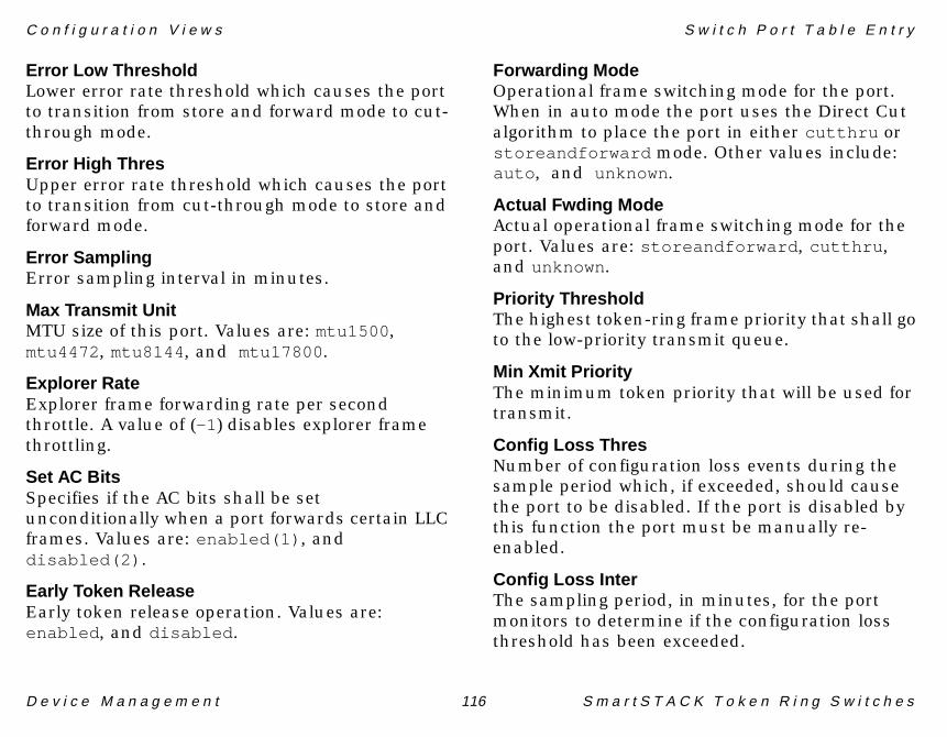
C o n f i g u r a t i o n V i e w s S w i t c h P o r t T a b l e E n t r y
D e v i c e M a n a g e m e n t 116 S m a r t S T A C K T o k e n R i n g S w i t c h e s
Error Low ThresholdLower error rate threshold which causes the port to transition from store and forward mode to cut-through mode.
Error High ThresUpper error rate threshold which causes the port to transition from cut-through mode to store and forward mode.
Error SamplingError sampling interval in minutes.
Max Transmit UnitMTU size of this port. Values are: mtu1500 , mtu4472 , mtu8144 , and mtu17800 .
Explorer RateExplorer frame forwarding rate per second throttle. A value of (-1 ) disables explorer frame throttling.
Set AC BitsSpecifies if the AC bits shall be set unconditionally when a port forwards certain LLC frames. Values are: enabled(1) , and disabled(2) .
Early Token ReleaseEarly token release operation. Values are: enabled , and disabled .
Forwarding ModeOperational frame switching mode for the port. When in auto mode the port uses the Direct Cut algorithm to place the port in either cutthru or storeandforward mode. Other values include: auto , and unknown .
Actual Fwding ModeActual operational frame switching mode for the port. Values are: storeandforward , cutthru , and unknown .
Priority ThresholdThe highest token-ring frame priority that shall go to the low-priority transmit queue.
Min Xmit PriorityThe minimum token priority that will be used for transmit.
Config Loss ThresNumber of configuration loss events during the sample period which, if exceeded, should cause the port to be disabled. If the port is disabled by this function the port must be manually re-enabled.
Config Loss InterThe sampling period, in minutes, for the port monitors to determine if the configuration loss threshold has been exceeded.

C o n f i g u r a t i o n V i e w s S w i t c h P o r t T a b l e E n t r y
D e v i c e M a n a g e m e n t 117 S m a r t S T A C K T o k e n R i n g S w i t c h e s
Bcast SuppressionThe number of broadcast frames per second allowed to be forwarded by this port. Any broadcast frames exceeding this watermark will not be forwarded by the port. Setting this object to 0 turns broadcast suppression off.
Time to LiveThe advertised time-to-live parameter on all CDP messages generated by the switch on this port.
Spanning Tree ModeUsed when configuring manual spanning tree. Setting this object to forwarding or blocking overrides the TrCRF's spanning tree's algorithm for this port. Other values include: auto , and unknown .
Security ModePort security mode is used to disable address learning at a port where an allow-source or allow-destination MAC address filter is configured. A value of normal indicates that the port is not configured for security. A value of secure-src-addrs indicates that learning for source addresses is disabled. A value of secure-dest-addrs indicates that learning for destination addresses is disabled. A value of secure-src-and-dest-addrs indicates that learning is disabled for both source and destination addresses.
LED StateThe state of the Link LED. Values are: on, off , and flash .
Operational ModePort operational mode. Values are: auto , port , station , ri-ro , passive-probe , and unknown .
Actual OperationThe actual port operation mode. If the port is in "auto mode," this object will return the mode in which the port opened. Values are: port , station , ri-ro , passive-probe , and unknown .
Duplex ModeDuplex mode. The port could either be auto detected or forced to HDX or FDX. Values are: auto , hdx , fdx , none , and unknown .
Note:Note:
Passive-probe mode can not be set with this object. The passive-probe mode is set automatically when a passive probe is defined in the Passive Probe Table.
Note:Note:
In Operation Mode, ri-ro is only valid for ports 19, 20, and ports on a fiber module.
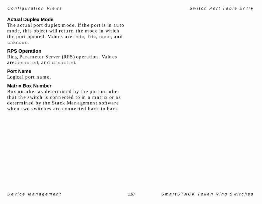
C o n f i g u r a t i o n V i e w s S w i t c h P o r t T a b l e E n t r y
D e v i c e M a n a g e m e n t 118 S m a r t S T A C K T o k e n R i n g S w i t c h e s
Actual Duplex ModeThe actual port duplex mode. If the port is in auto mode, this object will return the mode in which the port opened. Values are: hdx , fdx , none , and unknown .
RPS OperationRing Parameter Server (RPS) operation. Values are: enabled , and disabled .
Port NameLogical port name.
Matrix Box NumberBox number as determined by the port number that the switch is connected to in a matrix or as determined by the Stack Management software when two switches are connected back to back.

D e v i c e M a n a g e m e n t 119 S m a r t S T A C K T o k e n R i n g S w i t c h e s
Model Information Views
This section provides a brief description of the Model Information views available for models of SmartSTACKToken Ring switches in SPECTRUM.
Model Information views provide descriptive and configuration information about SPECTRUM models of individual devices, interfaces, and applications. Figure 14 shows an example of the Model Information view accessed from the Icon Subviews menu for the STS16 model’s Device icon. Model Information views are also available for each of the Interface icons in the Interface Device and Interface Device Topology views, and for each of the Application icons in the Application view. Although these views may vary slightly depending on the particular entity being modeled, their basic layout and content are similar for most SPECTRUM management modules. Therefore these views are described in more detail in the SPECTRUM Views documentation.
Figure 14:Figure 14:Figure 14:Figure 14: Model Information View
SpectroGRAPH: JK2
Primary Address
System Up Time
Manufacturer
Device Type
Serial Number
Network AddressNameContactDescriptionLocation
File View Help?Tools
MM Version Number
MM Name
MM Part Number
General Information
Model Created By
Model Type
Model Creation Time
Model State
Security String
Communication Information
Community Name
DCM TimeOut
DCM Retry
Poll/Log InformationPoll Interval
Polling Status
Mgmnt Protocol
Condition Value
Contact Status
Lost Child Count
Value When Yellow
Value When Orange
Value When Red
Last Successful Poll
LOGGED POLLED
Model Information View
Bookmarks
Primary ApplicationUser-Defined Type

D e v i c e M a n a g e m e n t Page 120 S m a r t S T A C K T o k e n R i n g S w i t c h
127
Index
Numerics802.1 VLAN 108
AAC Bits 116Act Port Mode 77, 87Active Monitor Process 52Actual Duplex 103Actual Duplex Mode 118Actual Fwd Mode 102Actual Fwding Mode 116Actual Operation 117Add Domain Management Table
Entry 27Add Entry 42, 44, 46, 91, 97, 112, 113Add Mapping Table Entry 46Add PVC Table Entry 43Add Trap Receiver Table Entry
view 97Addr Ageing 101Addr Ageing Time 115Addr In Mask 38Addr Out Mask 38Addr Reg Support 67Address Conn 68
Address Mask 46Address Translation Table 17Admin Lan ID 33Admin. Status 65, 75Administrative Status 16Age Level 99Aging Time 33, 90Application
CommonBridging
(GenBridgingApp) 26MIB-II (SNMP2_Agent) 26
Device-specific 25Icons 24
Application Icon 25Application Icons 25Application Views 24Apply Status 29Are Hop Count 28, 30ATM Address 42, 69ATM Uplink Application 42ATM Uplink Configuration 65ATM Uplink Module Indices 66ATM Uplink Performance View 53Automatically Reconfigure
Interfaces 74
BBandwidth 65, 75Bcast Suppression 117Bit Reversing 82Blocking Mode 114Boot Prom 66, 86BRF Configuration View 65BRF Deamon Conn. 95BRF No. 107BRF Server Conn. 94Bridge Forward Delay 34Bridge Hello Time 34Buffer Owner 29Burnt MAC Address 98
CCfg Loss 77, 87Cfg Loss Event 77, 88CFG Loss Int 102Cfg Loss Last RC 77, 88Cfg Loss Thr 77, 87Cfg Loss Thres 102Chassis Device Topology View 23Chassis Device View 13, 18

I n d e x I n d e x
D e v i c e M a n a g e m e n t Page 121 S m a r t S T A C K T o k e n R i n g S w i t c h
Cisco Trunk Port Information View 30
Cisco VLAN Information View 27Cisco VTP Application Performance
View 56Cisco VTP Applications 26Cisco VTP VLAN Editing View 28Colors
Interface Status Label 14Common VAP Configuration
View 67Concentrator Address 33Concentrator Relay Function
view 32Condition Status Label 25Config Loss Inter 116Config Loss Thres 116Configuration Options 104Configuration Views 64Configuration views 64Create Sub-Interfaces 74CRF No. 105Crosslink Ports 105Crosslink Table 105
DDefault Gateway 107Default Traffic Profile Mapping 45Default Traffic Profiles 43Demand Ageing 101
Demand Ageing Level 115Descr Param1 44Designated Root 35Destination MAC Filter 111Device Discovery after
Reconfiguration 74Device icon 8, 13, 24Device Views 13Device/Interface Number Label 14Devices supported by this module 8Diag LED 99Diagnostic 73, 85, 92Direction 104Discover LANs 74dot5 Statistics Information 51Download Status 94Download Switch 94DTR Concentrator Application
Performance View 56DTR Mac MIB Applications 51dtr Mode Select 52Dual Home 80Dual Home Address Table 84Duplex 103Duplicate/Trunk Configuration 114Dynamic 31Dynamic MAC Table 36
EEarly Tkn Rls 102
Early Token Release 116Enable Cur Conv 81, 82, 83, 84Encapsulation 31Error 92Error High Thres 116Error LED 99Error Low Threshold 116Error Sampling 101, 116Errors in Breakdown 61Eth Conversion 81, 82, 83, 84Ether Type 109Exit Mask 112Explorer Rate 70, 116Explorer Type 81, 82, 83, 84
FFast Ethernet Port Configuration 77Fast Ethernet Uplink Application 49Fast Ethernet Uplink
Configuration 76Fast Ethernet Uplink DS21143
View 49Fast Ethernet Uplink Performance
View 57Fast Ethernet Virtual Port
Configuration Table 79Fast Ethernet Virtual Port In
Discards View 58Fast Ethernet Virtual Port Novell
Protocol Table 49

I n d e x I n d e x
D e v i c e M a n a g e m e n t Page 122 S m a r t S T A C K T o k e n R i n g S w i t c h
Fast Ethernet Virtual Port Out Discards View 58
Fast Ethernet Virtual Port Protocols Table 81
Fast Ethernet Virtual Port SNA Protocol Table 83
Fast Ethernet Virtual Port SNA Protocol Table (w/ SNAP) 83
Fast Ethernet Virtual Port SNA Protocol Table (w/o SNAP) 84
FE Port Operational States 80Feature Key 98FEP Address 84Filter DSAPs 109Forward Delay 35Forwarding Mode 102, 116Framing Mode 72Functional Address Bitmask 52Fwd Delay 106
GGauge Label 15Generate Redundancy Alarms 74Generic Bridge App 58Guar Dest 69Guar VCC 69
HHello Time 35, 106High Error Thres 101High Speed Token Ring Uplink
Application 50HSTR Port Configuration State 88HSTR Port Configuration Table 87HSTR Port Operational State 91HSTR ThunderLAN Diagnostics
Table 50HSTR Uplink Configuration
Table 50HSTR Uplink Module Indices 86HSTR Uplink Performance View 59HSTR Virtual Port Configuration
Table 89HSTR Virtual Port Performance
View 60
IIcon mode 24Icon Subviews Menus
for Device icon 10for Interface icon 15
IconsDevice 8, 24Interface 14, 22
IF Status Label 14, 20In Joins 31
Index 32, 65, 67Index.Profile 44Index.Type 40Index.VAP.Map 45Instance 47Interface 14Interface Address Translation 73Interface Address Translation
Table 17, 94Interface Configuration Table 75Interface Configuration View 16, 64Interface Description Label 15Interface Detail View 16Interface Device Topology View 22Interface Device View 13, 22Interface Icon Subviews Menu 15Interface Icon Subviews Menu
Options 15Interface Icons 14Interface Number Label 14Interface Status Label
Definitions 14Interface Status View 16
Administrative Status 16Operational Status 16
Interface Threshold View 17Interface Type Label 15IP Address Label 15IP Address/Network Mask 65IP Frag 81IP State 107Isolating Soft Errors 51

I n d e x I n d e x
D e v i c e M a n a g e m e n t Page 123 S m a r t S T A C K T o k e n R i n g S w i t c h
LLabels
Application IconCondition Status 25Model Name 25Model Type 25
InterfaceIF Status Label 14Interface Number Label 14Interface Type Label 15Physical Address Label 15
ModuleModule Type 19
PortPort Status 20
Lan ID 33Last Change 65Learned Discards 33LEC ATM Address 69LEC Index 68LEC Vci 69LED 103LED State 117LED Status 67, 87LED Status Table 91Led Status Table 85LED Status View 73List mode 24Local Mode 26Low Error Thres 101
MMAC Address 33MAC Address Connections 71MAC Mib Performance View 60Man Domain 31Master Timing 72Matrix Box Number 118Matrix Status 95Max Age 106Max BCast 79Max Con Ctl 93Max Explore 90Max Explorer 102Max Line Rate 67Max MTU Size 95, 100Max Poll Data 93Max Rcv Win 93Max SVC 92Max Transmit 71, 101Max Transmit Unit 116Maximum Age 35Mcast MAC Addr 81Memory 98Message Log 66, 76, 87Message Logs View 72MIB-ll Performance View 60Min Xmit Priority 116Mode (Icon or List) 24Model 119Model Information View 17, 119Model Information views 119
Model type 8Model Type Label 25Modify FC 79Module 102Module Icon 18Module Icon Subviews Menu 19Module Info 96Module Label Icon Subviews
Menu 19Module Labels 19Module State 67Module States 68Module Type Values 100Mon. Port 104MRI Enable 33
NNative Vlan 31Net Bios 81NetBios Translational Bridging
Table 82Network I/O ports 22, 23No. of Bridge Relays 33No. of Conc. Relay Functions 33Non-Isolating Soft Errors 51Novell 81Number Matrix Mod 95Number of Ports 32Number VCC 67

I n d e x I n d e x
D e v i c e M a n a g e m e n t Page 124 S m a r t S T A C K T o k e n R i n g S w i t c h
OOperation 29Operation Mode 103Operation Status 65, 75Operational Mode 117Operational Status 16Other Protocols 81Out Adverts 31Out Joins 31Outbound Statistics Table 55
PPacket Break Down 61Packet Size 65, 75Parent 28, 30Passive Probe Table 104Performance View 54Performance Views 53Physical Address 65Physical Address Label 15Port Configuration 76, 86Port Configuration States 78Port Configuration View 101, 115Port Hardware 66Port Hardware Setup View 72Port Icon Subviews Menu 20Port Info 96Port Labels 20Port List 111, 113, 114
Port Mapping 79, 80, 84, 89, 91Port Mapping Information Table 84Port Mask 32, 98Port Mask Information View 40Port Mode 87, 106Port Out Mask 40Port Performance Statistic 20Port Performance View 60Power Supply Information View 41Priority 35Priority Thres 102Priority Threshold 116Probe/Crosslink Configuration
View 104Profile 69Profile Mapping 45Protocol 106Protocol Bridging 80Protocol Filter Table 109Protocol Specification 34Prune State 27Purpose and Scope 7PVC Connections View 42
QQos Class 44Quality of Service Classes 44Queue Length 65, 75
RReason Codes 78Receive Breakdown 61Reconfigure due to LINK UP/DOWN
events 74Reconfigure Model 74Redundancy Administrative
Status 74Redundancy and Model
Reconfiguration Options 73, 74Remote Box 112Remote Port 112Required Reading 7Reset Address Table 115Reset Addrs 101Reset Ctrs 101Reset Stats 115Restricted Rights Notice 2Rif Aging 80Rif Not Learn 80Ring Speed 52Ring Status 52RMON App 26RMON State Actual 95RMON State Conf 95Route Status in Static Route
Table 40Row Status 31, 42, 44, 46, 80, 91RPS Oper 103RPS Operation 118Rx High Bytes 48

I n d e x I n d e x
D e v i c e M a n a g e m e n t Page 125 S m a r t S T A C K T o k e n R i n g S w i t c h
Rx Low Bytes 49Rx Rate Dif 70
SSAID 28, 30Secondary Address Panel 17Security 103Security Mode 79, 90, 117Serial ports 22, 23Set AC Bits 102Signal Loss 73Signalling Configuration View 92SNA 81SNA Translational Bridging
Table 83SNMP Agent Detail View 61SNMP Capabilities 96Source MAC Address 113Source MAC Filter 112SPAN Mon 98SPAN Port 98Spanning 79, 90Spanning Mode 70Spanning Tree 102Spanning Tree Hold Time 34Spanning Tree Information View 34Spanning Tree Mode 117Spanning Tree Table 35Specific VAP 68Specific VAP Configuration 68
SPECTRUM Model 8Src Routing 81, 82, 83, 84SSCOP Configuration 93SSCOP Configuration View 93Stack Info 96Stack Status 95State 71, 88, 90Static MAC 38Static Route Table 39Static/Dynamic Filtering View 35Static/Dynamic Table 38Status of Dynamic MAC Table
Entries 36Status of Dynamic Route Table
Entries 37Status of Static MAC Table
Entries 39Ste Hop Count 28, 30STP Mode 108Stp Type 28, 30Stream Neighbor 52STS16 8STS16 Application View 24STS16 Applications 41STS16 Chassis Device View 18STS16 Configuration View 73STS16 Stack Configuration View 94STS16-20D 8STS16-20FRM 8STS16-20R 8STS16-20RM 8Supported Applications 25
Supported Devices 8Svc Support 67Switch Config 95Switch Module Information View 99Switch Module Table Entry 19Switch Performance View 62Switch Port Performance View 62Switch Port Table Entry 115Switch Stack Configuration View 97
TT301 (CONNECT) 92T308 (RELEASE) 92T309 (SAAL) 92T310 (SETUP) 93T313 (CONNECT) 93T316 (RESTART) 93T317 (RESTART) 93T322 (STATUS) 93Tag Protocol 77, 87Tagging Mode 79, 90TFTP Pathname 27TFTP Server 27TFTP Server IP 94Topologically Relocate Model 74Topology View 9TR Conversion 81, 82, 83, 84TR Func Addr 82Trace Mask 78, 88Trademarks 2
I n d e x I n d e x
D e v i c e M a n a g e m e n t Page 126 S m a r t S T A C K T o k e n R i n g S w i t c h
Traffic Descriptor Values 48Traffic Profile 42Traffic Profile View 43Transmit Breakdown 61Transport Mode 109, 115Trap Receiver 96Trap Receiver Information View 96TrBRF Configuration 108TrBRF Configuration View 107TrBRF Traps On 97TrBRFs in Domain 108TrCRF Configuration Table 105TrCRF Configuration Table
Entry 107TrCRF Configuration View 105TrCRFs in Domain 107TrCRFs SPAN Monitored 99Trunk Protocol Table 114Tx Frame Discard 48Tx Frames 48Tx High Bytes 48Tx Low Bytes 48Tx Rate Dif 70Type 44, 46, 111
UUsage 47Usage Values 47
VVA{ LANE and Outbound
Performance View 64VAP 55VAP Configuration 66VAP Index 42VAP LANE and Outbound
Performance View - ATM Diagnostics View 55
VAP Lane Statistics Table 55VAP States 71VAP Traffic Profile Mapping View 45VCC Creation Values 47VCC Status 46VCI 72Views
Configuration 64Interface Configuration 64Port Configuration 115Topology 9
Virtual Port 76, 85, 87, 89Virtual Port Mapping Table 85Virtual Port Security Mode 90Virtual Port Statistics Table 57VLAN Edit Buffer Table 29VLAN Max Storage 28VLAN State 27, 29VLAN Type 27, 29VPI 72VTP Enabled 32
XXmit Priority 102