
SmartMedia TM Format Introductionaeb/linux/smartmedia/SmartMedia_Format.pdf · Device driver File...
28
Product Planning & Application Engineering The Leader in Memory Technology ELECTRONICS 1999. 07.13 SmartMedia SmartMedia TM TM Format Introduction Format Introduction (Software Considerations) (Software Considerations) Memory Product & Technology Division
Transcript of SmartMedia TM Format Introductionaeb/linux/smartmedia/SmartMedia_Format.pdf · Device driver File...

Product Planning &Application Engineering The Leader in Memory Technology
ELECTRONICS
1999. 07.13
SmartMediaSmartMediaTMTM Format IntroductionFormat Introduction(Software Considerations)(Software Considerations)
Memory Product &Technology Division

Product Planning &Application Engineering The Leader in Memory Technology
ELECTRONICS
Contr.(FTL)
NANDFlash
Host System
ATAI/F
I/O Bus
q High overhead cost forcard assembly
q Flash file managementby controller-proprietaryfirmware
NAND I/F
• SmartMedia
NANDFlash
q No overhead cost for assembly
q Direct access by host system bus
q Flash file management by hostfirmware needs to bestandardized for compatibility
MPU
FirmwareROM
Why Standard File System for SmartMedia?Why Standard File System for SmartMedia?
MPU
System Bus
• PCMCIA card

Product Planning &Application Engineering The Leader in Memory Technology
ELECTRONICS
1. The essential specification for developer.
- SmartMedia Logical Format Specification(Ver 1.11, 99.4)
- SmartMedia Physical Format Specification(Ver 1.20, 99.4)
** Non-members are not given access to specifications. Anyone who want to
get this specifications should be a member of the SSFDC Forum
(URL: www.ssfdc.or.jp)
2. Other useful Specificaton.
- SmartMedia Physical Specification(Ver 1.11, 99.4)
- SmartMedia Application Specification(Ver 1.0,97.9)
- SmartMedia Electronics Specification(Ver 1.20, 98.12)
- SmartMedia LogoMark Interface Specification(Ver 1.00, 97.11)
- SmartMedia Voltage,Volume Guideline Specification(Ver 1.00, 98.12)
- SmartMedia Interface Guideline Specification(Ver 1.00,98.12)
- SmartMedia Compatibility Guideline(Ver 1.00,99.4)
SmartMedia Specification ListSmartMedia Specification ListAlready standardized up to 128MB SmartMedia !

Product Planning &Application Engineering The Leader in Memory Technology
ELECTRONICS
How Logical/Physical Structures are interrelatedHow Logical/Physical Structures are interrelated
Physical Structure
0 Block
1 Block
2 Block
3 Block
4 Block
5 Block
6 Block
MBR
PBR,FAT,Dir
003 Cluster
004 Cluster
005 Cluster
006 Cluster
Logical StructureSector0~ Sector31
Sector32~ Sector63
Sector64~ Sector95
Sector96~ Sector127
Sector128~ Sector159
Sector160~ Sector191
Sector192~ Sector223
Bad Block
CIS Block
MBR
PBR,FAT,Dir
Bad Block
004 Cluster
002 Cluster
005 Cluster
010 Cluster
7 Block
8 Block
002 Cluster
Irrelevant to physical address, logical structures are pre-defined and gives flexibility in the memory usage

Product Planning &Application Engineering The Leader in Memory Technology
ELECTRONICS
Application
FAT management
Device driver
File
Logical ¡ ¡Sector
Physical ¡ ¡Address
SmartMedia Logical Structure- DOS/FAT File System Management- Logical Sector Concept - Master Boot Sector- Partition Boot Sector (ClusterSize,SectorSize Total Cluster,etc)- FAT1,2- Root Directory- Using LBA Mode
SmartMedia Physical Structure - Zone boundary Concept - Card Information Structure /Identify Drive Information Block - Data Status Flag - Block Status Flag - ECC Area
Physical Format Specification. Logical Format Specification
SmartMediaTM
Physical / Logical FormatPhysical / Logical Format

Product Planning &Application Engineering The Leader in Memory Technology
ELECTRONICS
Block No.000 (CIS)Block No.001Block No.002Block No.003
Block No.510Block No.511
Page No.00Page No.01Page No.02Page No.03
Page No.14Page No.15
NAND Structure264Bytex16Pages x 512Blocks
Block Structure1Block=16Page
Block No.000 (CIS)Block No.001Block No.002Block No.003
Block No.510Block No.511
Block No.1022Block No.1023
Page No.00Page No.01Page No.02Page No.03
Page No.14Page No.15
NAND Structure528Bytex16,32Pages x 512Blocks
Block Structure1Block=16,32Page
512-515516517
518-519520-522523-524525-527
Data Area-1
Data Area-20-255
256-511
Reserved AreaData Status FlagBlock Status FlagBlock Address-1
ECC Area-2Block Address-2
ECC Area-1
Sector Data Structure1Sector=1Page
Sector Data Structure1Sector=2Pages
256257258259260261262263
Data Area-1
Reserved Area
Data Status FlagBlock Status Flag
Block Address-1
0-255 Data Area-2
ECC Area-2
Block Address-2
ECC Area-1
Even Page Odd Page
2MByte
4MByte
8MByte
HigherDensities
What is Physical Format?What is Physical Format?
Product Planning &Application Engineering The Leader in Memory Technology
ELECTRONICS
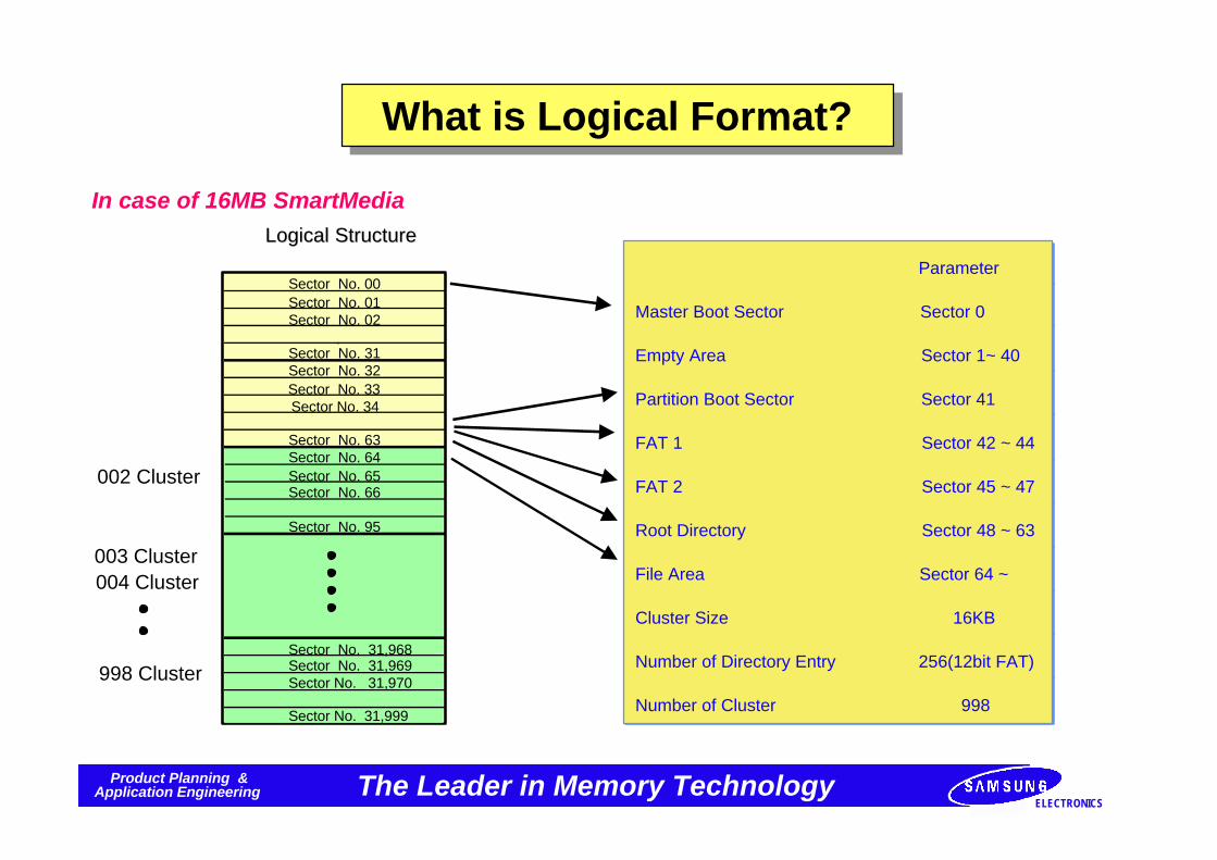
Sector No. 00Sector No. 01Sector No. 02 .Sector No. 31Sector No. 32Sector No. 33Sector No. 34
Sector No. 63Sector No. 64Sector No. 65Sector No. 66
Sector No. 95
Sector No. 31,968Sector No. 31,969Sector No. 31,970
Sector No. 31,999
Logical StructureLogical Structure
Parameter
Master Boot Sector Sector 0
Empty Area Sector 1~ 40
Partition Boot Sector Sector 41
FAT 1 Sector 42 ~ 44
FAT 2 Sector 45 ~ 47
Root Directory Sector 48 ~ 63
File Area Sector 64 ~
Cluster Size 16KB
Number of Directory Entry 256(12bit FAT)
Number of Cluster 998
002 Cluster
003 Cluster004 Cluster
998 Cluster
In case of 16MB SmartMedia
What is Logical Format?What is Logical Format?

Product Planning &Application Engineering The Leader in Memory Technology
ELECTRONICS
Addr Contents
000102030405060708090A0B0C0D0E0F101112131415161718191A1B
01h03hD9h01hFFh18h02hDFh01h20h04h00h00h00h00h21h02h04h01h22h02h01h01h22h03h02h04h07h
Tuple ID(CIS TPL_Device)Link to Next TupleDevice Type : I/O, Rate : 250nsDevice Size : 2 K ByteEnd of Device ID TupleTuple ID(CIS TPL_JEDEC_C)Link to Next TupleJEDEC Manufacture ID(PC Card ATA)JEDEC Device ID(VPP not required)Tuple ID(CIS TPL_MANF ID)Link to Next TupleManufacture CodeManufacture CodeManufacture Info.Manufacture Info.Tuple ID(CIS TPL_FUNC ID)Link to Next TuplePL FID_FUNCTIONTPL_FID_SYS INITTuple ID(CIS TPL_FUNCE)Link to Next TupleDisk Device Interface TuplePC Card ATA InterfaceTuple ID(CIS TPL_FUNCE)Link to Next TuplePC Card ATA Extension TupleATA Function Byte1ATA Function Byte2
Data Addr Contents
1C1D1E1F202122232425262728292A2B2C2D2E2F3031323334353637
1Ah05h01h03h00h02h0Fh1Bh08hC0hC0hA1h01h55h08h00h20h1Bh0AhC1h41h99h01h55h64hF0hFFhFFh
Tuple ID(CIS TPL_CONFIG)Link to Next TupleField Size ByteLast Entry in the Card Configuration TableCCR Base Address(Low-order Byte)CCR Base Address(High-order Byte)CCR Present MaskTuple ID(CIS TPL_CFTABLE_ENTRY)Link to Next TupleConfiguration Table Index ByteInterface Description FieldFeature Selection BytePower Parameter Selection BytePower Voltage(5V)Memory Space(Low-order byte)Memory Space(High-order byte)Miscellaneous (ex: CCSR power down)Tuple ID(CIS TPL_CFTABLE_ENTRY)Link to Next TupleConfiguration Table Index ByteInterface Description FieldFeature Selection BytePower Parameter Selection BytePower Voltage(5V)I/O Space Description ByteInterrupt IRQ Condition Info.Interrupt IRQs 0 to 7Interrupt IRQs 8 to 15
Data
CIS (Card Information System) Area (1 and 2) ICIS (Card Information System) Area (1 and 2) I

Product Planning &Application Engineering The Leader in Memory Technology
ELECTRONICS
38393A3B3C3D3E3F404142434445464748494A4B4C4D4E4F50515253
5455565758595A5B5C5D5E5F606162636465666768696A6B6C6D
6E-7F
Addr Contents
20h1Bh0Ch82h41h18hEAh61hF0h01h07hF6h03h01hEEh1Bh0Ch83h41h18hEAh61h70h01h07h76h03h01h
Miscellaneous (ex: CCSR power down)Tuple ID [I/O Primary]Link to Next TupleConfiguration Table Index ByteInterface Description FieldFeature Selection ByteI/O Space Description ByteI/O Range Description ByteI/O Address Range(01F0h-01F7h)I/O Address Range(01F0h-01F7h)8 BytesI/O Address Range(03F6h-03F7h)I/O Address Range(03F6h-03F7h)2 BytesIRQ Condition Info. (IRQ14)Tuple ID[I/O secondary]Link to Next TupleConfiguration Table Index ByteInterface Description FieldFeature Selection ByteI/O Space Description ByteI/O Range Description ByteI/O Address Range(0170h-0177h)I/O Address Range(0170h-0177h)8 BytesI/O Address Range(0376h-0377h)I/O Address Range(0376h-0377h)2 Bytes
Data Addr Contents
EEh15h14h05h00h20h20h20h20h20h20h20h00h20h20h20h20h00h30h2Eh30h00hFFh14h00hFFh00h
IRQ Condition Info. (IRQ14)Tuple ID(CIS TPL_VERS_1)Link to Next TupleMajor Version Number[Ver.5]Minor Version Number[Ver.0]Name of ManufactureName of ManufactureName of ManufactureName of ManufactureName of ManufactureName of ManufactureName of ManufactureEnd of Manufacture NameName of ProductName of ProductName of ProductName of ProductEnd of Product NameProduct Version “0”Product Version "."Product Version "0"End of Product VersionEnd of Product Info. TupleCIS TPL_NO_LINKLink to Next TupleCIS TPL_ENDNull-Tuple
Data
CIS (Card Information System) Area (1 and 2) IICIS (Card Information System) Area (1 and 2) II

Product Planning &Application Engineering The Leader in Memory Technology
ELECTRONICS
Logical Format ParameterLogical Format Parameter
1 MB
NumCylinder
NumHead
NumSector
SumSector
SectorSize
125
4
4
2,000
512
2 MB
125
4
8
4,000
512
4 MB
250
4
8
8,000
512
8 MB
250
4
16
16,000
512
16 MB
500
4
16
32,000
512
32 MB
500
8
16
64,000
512
64 MB
500
8
32
128,000
512
128 MB
500
16
32
256,000
512

Product Planning &Application Engineering The Leader in Memory Technology
ELECTRONICS
Master Boot Record (MBR) 1Master Boot Record (MBR) 1
Offset Size(Bytes) Description
000H
1BEH
1CEH
1DEH
1EEH
1FEH
446
16
16
2
16
16
Boot code
Partition Entry
Partition Entry
Partition Entry
Signature Word(0x55AA)
Partition Entry
The Master Boot Record contains the following fields:

Product Planning &Application Engineering The Leader in Memory Technology
ELECTRONICS
Master Boot Record (MBR) 2Master Boot Record (MBR) 2
Offset Size(Bytes) Description
00H01H
02H
03H04H
05H
06H
07H
111
11
x86 Default Boot Partition (00H=Not Default, 80H=Default)StartHead-Zero-based(0)head number
StartSector-Zero-based(1) sector number. Bits 6 and 7 are
high bits of zero-based(0) cylinder number.
Partition Type
00H:Unknown or deleted if NumSectors is zero
01H:MS-DOS 12-bit BPB/FAT < 16 MB
04H:MS-DOS 16-bit BPB/FAT < 32 MB
05H:Extended MS-DOS Partition
06H:MS-DOS 16-bit BPB/FAT >= 32 MB
StartCylinder
NumSectors08H
0CH
Each of the four Partition Entries in the Master Boot Record have the following format:
EndHead-Zero-based(0)head number
EndSector-Zero-based(1) sector number. Bits 6 and 7 are
high bits of zero-based(0) cylinder number.
EndCylinder
StartSector(relative to beginning of Extended MS-DOS)
1
1
1
4
4

Product Planning &Application Engineering The Leader in Memory Technology
ELECTRONICS
Partition Boot Record (PBR)Partition Boot Record (PBR)The Partition Boot Record contains the following fields
Offset Size(Bytes) Description
000H003H
00BH
024H
025H026H027H
02BH
3
825
1
1
1
411
8
448
2
JMP instruction to PBR boot code
OEMName and version
BIOS Parameter Block (BPB)
DriverNumber(00H=Floppy,80H=Fixed)
VolumeLabel-ASCII characters. Padded with blanksif less than eleven (11) characters.
ExtBootSignature-29HVolumeID or Serial Number
Reserved, do not use.
FileSysType-ASCII Characters identifying file system type.Padded with blanks if less than eight (8) characters. One ofThe following values:
Value
FAT12
Meaning
FAT16
12-bit File Allocation Table (FAT)
16-bit File Allocation Table (FAT)
Boot code
Signature word - 55AAH
036H
03EH
1FEH

Product Planning &Application Engineering The Leader in Memory Technology
ELECTRONICS
BIOS Parameter Block (BPB)BIOS Parameter Block (BPB)The BIOS Parameter Block(BPB) contains the following fields:
Offset Size(Bytes) Description
000H002H
003H
005H006H008H
00AH
21
2
2
1
2
1
4
4
BytesPerSector-Number of bytes per sectorSectorsPerCluster-Number of sectors in a clusterReservedSectors
NumFATs-Number of FAT on the media
TotalSectors If Sector is over 65,535, this field is zero andactual number of sectors is in the HugeSectors field.
MedialDByte-Used to quickly identify how the media is formatted.
RootDirEntries-Number of Root Directory entries
F0H:Various types of media F8H: Hard disk, any sizeF9H:720 KB 3.5” or 1.2 MB 5.25” FAH:320 KB 5.25”FBH:640 KB 3.5” FCH:180 KB 5.25”FDH:360 KB 5.25” FEH:160 KB 5.25”FFH:320 KB 5.25”NumFATSectors-Number of sectors in each FAT
SectorsPerTrack-Number of sectors on a track
00BH
011H
015H
NumHeads-Number of heads
HiddenSectors-Number of hidden sectors
HugeSectors-Number of sectors if Total sectors is zero.
00DH00FH
22
2

Product Planning &Application Engineering The Leader in Memory Technology
ELECTRONICS
Spare Area Information (1 MB, 2 MB)Spare Area Information (1 MB, 2 MB)
To manage data in 256-Byte unit, pages are handled in pairs.
Spare Area Configuration (Even+Odd page.16Byte)
Byte No. Even-numbered page Odd-numbered page
User Data Area
User Status Area
Block Status Area
Block Address Area-1
ECC Area-2
ECC Area-1
Block Address Area-2
256257258259260261
262
263

Product Planning &Application Engineering The Leader in Memory Technology
ELECTRONICS
Spare Area Information (4 ~128 MB)Spare Area Information (4 ~128 MB)
Manage data in 512-Byte unit per page.
Spare Area Configuration (16 Byte)
Byte No. Contents Contents
User Data Area
User Status Area
Block Status Area
Block Address Area-1
ECC Area-2
ECC Area-1
Block Address Area-2
512513514515516517
518
519
Byte No.
520521
522523
524525
526
527

Product Planning &Application Engineering The Leader in Memory Technology
ELECTRONICS
Block Address Area InformationBlock Address Area Information
The data in this area indicates address information on the conversion table to be consulted for block-logical-address to physical-address conversion
Block Address Configuration
D7 D6 D5 D4 D3 D2 D1 D0 1, 2 MB SM 4, 8, 16 MB SM
0262 bytes(even)
259 bytes(odd)518, 523 bytes0 0 1 0 BA9 BA8 BA7
BA6 BA5 BA4 BA3 BA2 BA1 BA0 P263 bytes(even)
260 bytes(odd)519, 524 bytes
BA9 ~ BA0 : Block Address(values=0 through n,where n = maximum logical block count - 1)
P : Even Parity bit
Block addresses referred to here represent addresses obtained in the form of data segments after logical addresses
have been separated by individual erasure blocks.

Product Planning &Application Engineering The Leader in Memory Technology
ELECTRONICS
FAT(File Allocation Table) ContentFAT(File Allocation Table) Content
In case of 12-bit FAT
Offset Content Description
00h - 02h F8h, FFh, FFh FAT ID (3 Bytes)
03h and after 00h
In case of 16-bit FAT
Offset Content Description
00h - 03h F8h,FFh,FFh,FFh FAT ID (4 Bytes)
04h and after 00h
FAT Content
12-bit FAT 16-bit FAT Description
000h 0000h Unused Cluster
001h 0001h Reserved
002h - FEFh 0002h - FFEFh Next Cluster Number in the chain
FF0h - FF6h FFF0h - FFF6h Reserved
FF7h FFF7h Defective Cluster
FF8h - FFFh FFF8h - FFFFh Last Cluster in the chain

Product Planning &Application Engineering The Leader in Memory Technology
ELECTRONICS
Example of FAT OperationExample of FAT Operation
In case of 12-bit FAT
002h - FEFh ( Next Cluster Number in the chain) => About 4000 Cluster
0 3h 2 0h 0 1h
0 0 3 h 0 1 2 h
Example
Location 002 003 004 005 006 007 008 009 00A 00B 00C 00D 00E 00F 010 011 012 …
Value 003 h 012h FFFh FFFh 008h 123h 009h FFFh 222h 543h FFFh E34h 093h 453h 765h 876h 006h ...
In case of Start Cluster ‘002h’ in file information 32Byte
Cluster chain ==> 002h,003h,012h,006h,008h,009h.

Product Planning &Application Engineering The Leader in Memory Technology
ELECTRONICS
Directory ContentDirectory Content
32 Byte Information
Byte Content Initialization Value
0 - 7 File Name *00h, F6h . . . . . . F6h
8 - 10 Extension F6h, F6h, F6h
11 Attribute F6h
12 - 21 Reserved F6h, F6h . . . . . . F6h
22 -23 Time F6h, F6h
24 -25 Date F6h, F6h
26 -27 Start Cluster Number F6h, F6h
28 - 31 File Size F6h, F6h, F6h, F6h
*00h : Unused Directory
E5h : Deleted Directory
2Eh : Sub Directory
Examples
43 443 4F 4E 46 49 47 20 20 53 59 53 20 00 00 00 00 F 4E 46 49 47 20 20 53 59 53 20 00 00 00 00 ConfigConfig.sys.sys
00 00 00 00 00 00 25 43 AF 20 02 00 9C 03 00 0000 00 00 00 00 00 25 43 AF 20 02 00 9C 03 00 00
In case of SmartMedia, Initialization Values are all zero.

Product Planning &Application Engineering The Leader in Memory Technology
ELECTRONICS
f8 ff ff ff 0f 0 0 0 0 0 0 0 0 0 0 0 0 0 0 0 0 .... ff ff ff ff ff ff 10 2 ff ff ff 10 2 aa aa 97
41 20 20 20 20 20 20 20 54 58 54 0 ... 97 89 ba 22 2 (32 Bytes) 0... ff ff ff ff ff ff 10 4 ff ff ff 10 4 ab a5 6b
4142 43 44 45 ... 59 5a d a 0 0 0 ... ff ff ff ff ff ff 10 7 ff ff ff 10 7 56 aa 67
FAT
Dir
File
After Copy A.TXT
( Content: ABCDEFGHIJKLMNOPQRTUVWXYZ )
f8 ff ff ff fff ffff 0 0 0 0 0 0 0 0 0 0 0 0 0 0 0 .... ff ff ff ff ff ff 10 2 ff ff ff 10 2 aa aa 97
41 20 20 20 20 20 20 20 54 58 54 0 ... 97 89 ba 22 2 .. (32Byte) ) 41
41 41 20 20 20 20 20 20 20 20 10 ... 0 97 89 ba 22 3 .. (32 Bytes) 0 0 ff ff ff ff ff ff 10 4 ff ff ff 10 4 ab a5 6b
4142 43 44 45 ... 59 5a d a 0 0 0 ......(8 KBytes,1 Cluster) ff ff ff ff ff ff 10 7 ff ff ff 10 7 56 aa 67
2e 20 20 20 20 20 20 20 20 20 20 10 0 .. 0 97 89 ba 22 3 0..(32 Bytes)
2e 2e 20 20 20 20 20 20 20 20 20 10 0.. 0 97 89 ba 22 0 ..(32 Bytes) 0 .. ff ff ff ff ff ff 10 8 ff ff ff 10 8 c0 cf 3
FAT
Dir
File1
File2
Sub
After md AAAIf new Sub directory is made, File contextcontains Files.
Initial Format Data
Example of Copy,Del,Mkdir (16 MB)Example of Copy,Del,Mkdir (16 MB)
f8 ff ff 0 0 0 0 0 0 0 0 0 0 0 0 0 0 0 0 0 0 .... ff ff ff ff ff ff 10 2 ff ff ff 10 2 aa aa 97
0 0 0 0 0 0 0 0 0 0 0 0 0 0 0 0 0 0 0 0 0 ..... ff ff ff ff ff ff 10 4 ff ff ff 10 4 ff ff ff
ff ff ff ff ff ff ff ff ff ff ff ff ff ff ff ff ff ff ff ff ff ..... ff ff ff ff ff ff ff ff ff ff ff ff ff ff ff ff
FAT
Dir
File

Product Planning &Application Engineering The Leader in Memory Technology
ELECTRONICS
f8 ff ff ff ff ff ff 0f 0 0 0 0 0 0 0 0 0 0 0 0 0 ....
41 20 20 20 20 20 20 20 54 58 54 0 ... 97 89 ba 22 2 .. (32 Bytes) 41 41
41 20 20 20 20 20 20 20 20 10 ... 0 97 89 ba 22 3 .. (32 Bytes) ....
4142 43 44 45 ... 59 5a d a 0 0 0 ......(8 KBytes,1 Cluster)
2e 20 20 20 20 20 20 20 20 20 20 10 0 .. 0 97 89 ba 22 3 0..(32 Bytes)
2e 2e 20 20 20 20 20 20 20 20 20 10 0.. 0 97 89 ba 22 0 ..(32 Bytes)
42 20 20 20 20 20 20 20 54 58 54 0 ... 4d 6e 32 22 4 0 ... (32 Bytes) 0 0..
61 62 63 64 65 66 ... 79 7a d a 0 0 0 .....(8 KBytes,1 Cluster)
Copy B.TXT in AAA directory
( Content:abcdefghijklmnopqrstuvwxyz )
FAT
Dir
File1
File2
(Sub
Dir)
File3
f8 ff ff 0 f0 ff ff 0f 0 0 0 0 0 0 0 0 0 0 0 0 0 ....
e5 20 20 20 20 20 20 20 54 58 54 0 ... 97 89 ba 22 2 .. (32 Bytes) 41 41
41 20 20 20 20 20 20 20 20 10 ... 0 97 89 ba 22 3 .. (32 Bytes) ....
4142 43 44 45 ... 59 5a d a 0 0 0 ......(8 KBytes,1 Cluster)
2e 20 20 20 20 20 20 20 20 20 20 10 0 .. 0 97 89 ba 22 3 0..(32 Bytes)
2e 2e 20 20 20 20 20 20 20 20 20 10 0.. 0 97 89 ba 22 0 ..(32 Bytes)
42 20 20 20 20 20 20 20 54 58 54 0 ... 4d 6e 32 22 4 0 ...Z(32 Bytes)
61 62 63 64 65 66 ... 79 7a d a 0 0 0 .....(8 KBytes,1 Cluster)
FAT
Dir
File1
File2
(Sub
Dir)
File3
Delete A.TXT in Root directory
Example of Copy,Del,Mkdir (16MB)Example of Copy,Del,Mkdir (16MB)
* Spare Area is same as above page.
* Spare Area is same as above page.

Product Planning &Application Engineering The Leader in Memory Technology
ELECTRONICS
♦ ECC code consists of 3 Bytes per 256 Bytes(Hamming Code ECC Algo) - Actually 22 bit ECC code per 2048 bits - 22 bit ECC code = 16 bit line parity + 6 bit column parity
ECC Code Generation MethodECC Code Generation Method
♦ Error Detection Sequence
Generating and writing ECC code during program operation
Generating New ECC codeduring read data area
XOR original ECC code withnew generated ECC code
If results areall zero ?
No error Error detected
No
Yes
ECC code in Flash Memory (22 bits)
New generated ECC code during read
(XOR)
22 bit data = 0 11 bit data = 1 1 bit data = 1
(No Error)(Correctable error)(ECC error)

Product Planning &Application Engineering The Leader in Memory Technology
ELECTRONICS
12-bit FAT 16-bit FAT Description
000h 0000h Unused Cluster
001h 0001h Reserved
002h ~ FEFh 0002h ~ FFEFh Next Cluster Number in the chain
FF0h ~ FF6h FFF0h ~ FFF6h Reserved
FF7h FFF7h Defective Cluster
FF8h ~ FFFh FFF8h ~ FFFFh Last Cluster in the chain
1~ 64MB(250 ~ 4,000 Cluster Chain Needs) : 12bit FAT Operation128MB(8,000 Cluster Chain Needs) : 16bit FAT Operation
12bit FATUseful Cluster Number = 2 = 4096 (Approximately 4000 Cluster Count Available )
16bit FAT OperationUseful Cluster Number = 2 = 65536 (Approximately 64000 Cluster Count Available)
12bit FAT Specification Table
12
16
Considerations for High Density SmartMedia(1)Considerations for High Density SmartMedia(1)

Product Planning &Application Engineering The Leader in Memory Technology
ELECTRONICS
~ 32MB SmartMedia
I/O 0~ 7 Start Add. (3Cycle)
A0 ~ A7 & A9 ~ A24
WE
ALE
CLE
00H
WE
ALE
CLE
I/O 0~ 7 Start Add. (4Cycle)
A0 ~ A7 & A9 ~ A25(A26)
00H
Four address cycles are needed for 64MB and 128MB SmartMedia !
64MB,128MB SmartMedia
1st Cycle
2 nd Cycle
3 rd Cycle
4 th Cycle
Model
2MB
4MB
8MB
16MB
32MB
64MB
128MB
Address Configuration
Valid Page Address Fixed Low
PA0 ~ PA12 PA13 ~ PA 15
PA0 ~ PA12 PA13 ~ PA 15
PA0 ~ PA13 PA14, PA 15
PA0 ~ PA14 PA15
PA0 ~ PA15 -
PA0 ~ PA16
PA0 ~ PA17
PA17 ~ PA23
PA18 ~ PA23
CA0 ~ CA7 : column address
PA0 ~ PA7 : page address 1
PA8 ~ PA15 : page address 2
PA16 ~ PA23 : page address 3
Considerations for High Density SmartMedia(2)Considerations for High Density SmartMedia(2)

Product Planning &Application Engineering The Leader in Memory Technology
ELECTRONICS
Zone-based block management for 32MB,64MB and 128MB
Zone Physical Block Description
0
0 CIS/Identify Drive Information Area
1 ~ 1023 Data Area
(Logical Block : 0 ~ 999 )
0 ~ 1023 Data Area
(Logical Block :1000 ~1999 )
1
: ::
0 ~ 1023 Data Area
(Logical Block : Zone x 1000 + 999 )
* CIS/Identify Drive Information Area ==>Zone 0
Each zone has 1000 data blocks.
Considerations for High Density SmartMedia(3)Considerations for High Density SmartMedia(3)
Final Zone

Product Planning &Application Engineering The Leader in Memory Technology
ELECTRONICS
- CIS,DID,ID- MBR- Sector,Cluster Size in PBR
- File Read,Write,Update etc. - Search file information.- Calculate Cluster in FAT
Logical FormatHost System
Look-Up Table
- Link Logical Cluster(LBA mode) and Physical block- Update Block Status
Physical Format Basic Parameter Check - Read,Write Block- Update Block
Software Functional BlocksSoftware Functional Blocks

Product Planning &Application Engineering The Leader in Memory Technology
ELECTRONICS
Updating into empty blocks reduces memory demands andavoid excessive block usage
Bad Block
CIS Block
002 Cluster
005 Cluster
Bad Block
Empty Block
003 Cluster
0 Block
1 Block
2 Block
3 Block
4 Block
5 Block
6 Block
Bad Block
CIS Block
002 Cluster
Empty
Bad Block
005 Cluster (new)
003 Cluster
Erased
Copy the datawith the updates
to the emptyblock
Copy the datawith the updates
to the emptyblock
Data Updating ProcedureData Updating Procedure