
SMARTLOGGER ECS - gossenmetrawatt.com · WHAT CAN THE SMARTLOGGER ECS DO? The SMARTLOGGER ECS ......
40
Operating Instructions SMARTLOGGER│ECS Multifunctional Data Logger with Integrated Modem 3-349-654-03 1/9.11
Transcript of SMARTLOGGER ECS - gossenmetrawatt.com · WHAT CAN THE SMARTLOGGER ECS DO? The SMARTLOGGER ECS ......

Operating Instructions
SMARTLOGGER│ECS
Multifunctional Data Logger with Integrated Modem
3-349-654-03 1/9.11


SMARTLOGGER ECS
GMC-I Messtechnik GmbH 3
T A B L E O F C O N T E N T S
I. INTRODUCTION .......................................................................5 WHAT CAN THE SMARTLOGGER ECS DO? .................................5 BASIC FUNCTIONS / HIGHLIGHTS ....................................................5 SCHEMATIC DIAGRAM ....................................................................6 II. SMARTLOGGER ECS IN ACTUAL PRACTICE ........................7 1. System Description ..................................................................................................................................7 1.1. Data Communication and Interfaces..................................................................................................... 7 1.2. Inputs and Outputs................................................................................................................................ 8 1.3. Interfaces............................................................................................................................................... 8 1.4. Auxiliary Voltages.................................................................................................................................. 8 1.5. Power Supply / UPS.............................................................................................................................. 8 1.6. Hardware Layout................................................................................................................................... 8 1.7. Memory System .................................................................................................................................. 10 2. Hardware..................................................................................................................................................11 2.1. Connector Pin Assignments................................................................................................................ 11 2.2. Mains Connection ............................................................................................................................... 11 2.3. Digital Inputs ....................................................................................................................................... 12 2.4. Analog Inputs ...................................................................................................................................... 12 2.5. Digital Outputs..................................................................................................................................... 13 2.6. Rechargeable Battery ......................................................................................................................... 14 2.7. Auxiliary Voltages................................................................................................................................ 14 2.8. RS 485 interface ................................................................................................................................. 14 2.9. M-Bus Interface................................................................................................................................... 14 2.10. Visualization of Data Flow................................................................................................................... 15 2.11. DCD, Sync and Error LEDs................................................................................................................. 16 2.12. GSM Modem ....................................................................................................................................... 16 2.13. Analog/ISDN Modem .......................................................................................................................... 16 2.14. Ethernet............................................................................................................................................... 16 2.15. Expansion Module, 8 Digital Inputs..................................................................................................... 17 2.16. Expansion Module, 8 Analog Inputs ................................................................................................... 17 2.17. Expansion Module, 4 Relay Outputs................................................................................................... 17 3. Software...................................................................................................................................................18 3.1. General................................................................................................................................................ 18 3.1.1. System Requirements......................................................................................................................... 18 3.1.2. Starting the Program........................................................................................................................... 18 3.2. Operation............................................................................................................................................. 19 3.2.1. Menu Bar............................................................................................................................................. 19 3.2.2. Modem ................................................................................................................................................ 19 3.3. Devices................................................................................................................................................ 20 3.4. Setting Up a New Device .................................................................................................................... 22 3.5. Parameters Configuration ................................................................................................................... 24 3.5.1. Settings ................................................................................................................................................24 3.5.2. Phone...................................................................................................................................................25 3.5.3. Inputs....................................................................................................................................................28 3.5.4. Analog Sensors....................................................................................................................................29 3.5.5. Relays ..................................................................................................................................................31 3.5.6. Events ..................................................................................................................................................32 3.5.7. Rechargeable Battery ..........................................................................................................................33
SMARTLOGGER ECS
4 GMC-I Messtechnik GmbH
3.5.8. Diagnosis............................................................................................................................................. 33 3.5.9. Counting Pulses .................................................................................................................................. 34 3.5.10. Load Profile ......................................................................................................................................... 35 3.5.11. M-Bus Devices .................................................................................................................................... 36 3.5.12. Mod-Bus Devices ................................................................................................................................ 37 3.5.13. Firmware Update................................................................................................................................. 37 3.5.14. Modem................................................................................................................................................. 38
SMARTLOGGER ECS
GMC-I Messtechnik GmbH 5
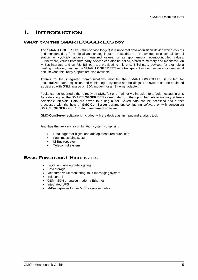
I. INTRODUCTION WHAT CAN THE SMARTLOGGER ECS DO?
The SMARTLOGGER ECS (multi-service logger) is a universal data acquisition device which collects and monitors data from digital and analog inputs. These data are transmitted to a central control station as cyclically acquired measured values, or as spontaneous, event-controlled values. Furthermore, values from third party devices can also be polled, stored to memory and monitored. An M-Bus interface and an RS 485 port are provided to this end. Third party devices, for example a heating controller, can use the SMARTLOGGER ECS as a transparent modem via an additional serial port. Beyond this, relay outputs are also available. Thanks to the integrated communications module, the SMARTLOGGER ECS is suited for decentralized data acquisition and monitoring of systems and buildings. The system can be equipped as desired with GSM, analog or ISDN modem, or an Ethernet adapter. Faults can be reported either directly by SMS, fax or e-mail, or via intrusion to a fault messaging unit. As a data logger, the SMARTLOGGER ECS stores data from the input channels to memory at freely selectable intervals. Data are saved to a ring buffer. Saved data can be accessed and further processed with the help of GMC-ComServer parameters configuring software or with convenient SMARTLOGGER OFFICE data management software. GMC-ComServer software is included with the device as an input and analysis tool. And thus the device is a combination system comprising:
Data logger for digital and analog measured quantities Fault messaging system M-Bus repeater Telecontrol system
BASIC FUNCTIONS / HIGHLIGHTS
Digital and analog data logging Data storage Measured value monitoring, fault messaging system Telecontrol GSM, ISDN or analog modem / Ethernet Integrated UPS M-Bus repeater for ten M-Bus slave modules

SMARTLOGGER ECS
6 GMC-I Messtechnik GmbH
SCHEMATIC DIAGRAM
Figure 1: Schematic System Layout
Energy Meter
Fault Messaging
ECS
Heat Meter
Communication between the heating systems and control station has top priority.
3rd Party Device
e.g. Heating
Controller
OperatingData
e.g. Temp.Humidity ...
RS 232
GSM or Analog TC
Control Station
M-Bus

SMARTLOGGER ECS
GMC-I Messtechnik GmbH 7
II. SMARTLOGGER ECS IN ACTUAL PRACTICE
1. SYSTEM DESCRIPTION
1.1. DATA COMMUNICATION AND INTERFACES
One of the special features of the SMARTLOGGER ECS is transparent data transmission between third party devices, in this case a heating controller, and a control station.
Figure 2: Data Transmission Between Third Party Device and Control Station The various communication channels are represented in a simplified fashion in the schematic diagram. Communication with the system takes place from two different locations in this case. For example, communication only takes place with the third party device via control station 1 (red communication channel). On the one hand, parameter settings need to be transferred to the device, and on the other hand, the third party device needs to be able to transmit fault messages to control station 1. It has to be possible to query stored data from the SMARTLOGGER ECS via control station 2, and the SMARTLOGGER ECS should also be able to transmit fault messages to control station 2.
ECS
RS 232
Heating Controller
RS 232
Control Station 1 with Original Software for the Third Party Device
Control Station 2 with Software for SMARTLOGGER ECS
GMC-ComServer or SMARTLOGGER Office
IntegratedModem
I/OSystem RS 485 M-Bus
Micro-controller
Heat Meter
TCConnection

SMARTLOGGER ECS
8 GMC-I Messtechnik GmbH
For this reason, the following conditions must be observed with regard to data communication: Communication between the third party device (heating system) and control station 1 always has
precedence. As regards communication with the heating unit, the system must be compatible with equipment
from any manufacturer. The transmission protocol is for the most part insignificant in this respect. The physical interface is an RS 232 port.
The system must automatically detect whether any given data packet is intended for the third
party system (heating system or M-Bus system), or for itself. This applies to both transmission directions, because the third party system is itself capable of dispatching fault messages to the control station.
1.2. INPUTS AND OUTPUTS
The following I/O structure is provided for the acquisition of fault messages and operating data: 4 digital inputs 4 analog inputs (4 to 20 mA, 0 to 10 V, NTC) 2 fault message outputs via relays (for extra-low voltage) 2 fault message outputs via semiconductor outputs
1.3. INTERFACES
RS 232 port for communication with the third party device USB port for communication with the microcontroller system (currently in preparation) RS 485 port for communication with expansion modules M-Bus interface for communication with M-Bus terminal devices, for up to ten units
1.4. AUXILIARY VOLTAGES The device provides an unregulated voltage of approximately 17 V DC and a regulated voltage of 5 VD C as supply power for S0 inputs or sensors.
1.5. POWER SUPPLY / UPS The system is supplied with 230 V AC. Integrated standby power system switching is combined with an external rechargeable battery (12 V DC 2.1 Ah).
1.6. HARDWARE LAYOUT
The system is laid out in a consistently modular fashion and can thus be varied nearly unrestrictedly with reference to communication, as well as the number of I/Os, and can be adapted to the respective project. The device is enclosed in an extruded profile housing to this end. Two standard lengths are available at the moment, and this can of course be varied depending upon project requirements.

SMARTLOGGER ECS
GMC-I Messtechnik GmbH 9
Basically, the SMARTLOGGER ECS consists of: Communication module Main board Microcontroller board
Expansion options with up to 4 expansion modules in an extruded profile housing:
Expansion module with 4 digital outputs Expansion module with 8 digital inputs Expansion module with 8 analog inputs
Step 1: Select the communication module. GSM modem (shown in figure) Analog modem ISDN terminal adapter Ethernet interface Always on-board: interface for 3rd party devices
Step 2: Add the main board. Switched-mode power supply 4 digital inputs 4 analog inputs 4 digital outputs M-Bus, RS 485
Step 3: Add the microcontroller board. Programming interface After completing this step, the SMARTLOGGER ECS has been equipped with all of its basic features.
Step 4: Install expansion modules. In this case, 4 digital outputs via bistable
relays Also available: 8 digital inputs 8 analog inputs
Step 5: Attach the right-hand side cover.

SMARTLOGGER ECS
10 GMC-I Messtechnik GmbH
1.7. MEMORY SYSTEM
Due to the fact that the SMARTLOGGER ECS is equipped with a variable number of inputs and outputs, the memory system has to be laid out in a correspondingly variable manner. To a great extent, the parameter settings for the memory system depend on the respective project. In the case of standardized tasks, for example 12-channel fault messaging, the system’s parameters can be configured at the factory and the unit is thus ready for immediate use. Parameter settings can of course be changed at any time. The other extreme would involve, for example, a complex individual project, as is common in the field of facility management, for which the SMARTLOGGER ECS has been equipped with several internal expansion modules and additional data needs to be queried via the M-Bus, as well as external expansion modules. In cases of this sort, the memory system has to be individually configured by assigning a separate memory location to each internal and external data source. The respective parameters are configured with the help of GMC-ComServer software.
At its current stage of development, the system is capable of managing up to 20 digital inputs, 12 analog inputs and 32 data sources in the form of M-Bus devices. Memory depth depends on the respective parameter settings and can be calculated as follows: One measuring period consists of: 4 bytes UTC + 2 bytes length + 4 bytes x number of digital inputs + 2 bytes x number of analog inputs + 6 bytes x number of M-Bus values Sample calculations: Twelve digital inputs, four analog inputs and three M-Bus values need to be saved: With 2,000,000 bytes of MP memory, 80 bytes per measuring period result in 25,000 MP. A 15 minute MP results in a memory depth of 260 days! Twelve analog inputs need to be saved: With 2,000,000 bytes of MP memory, 30 bytes per measuring period result in 66,666 MP. A 15 minute MP results in a memory depth of 694 days! The measuring period can be set to 1, 5, 15 or 60 minutes.
SMARTLOGGER ECS
GMC-I Messtechnik GmbH 11
2. HARDWARE
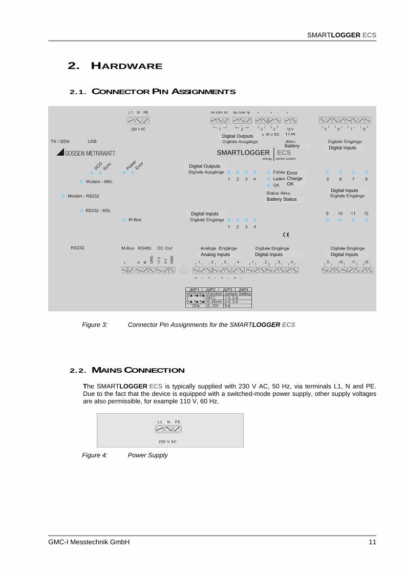
2.1. CONNECTOR PIN ASSIGNMENTS
Figure 3: Connector Pin Assignments for the SMARTLOGGER ECS
2.2. MAINS CONNECTION The SMARTLOGGER ECS is typically supplied with 230 V AC, 50 Hz, via terminals L1, N and PE. Due to the fact that the device is equipped with a switched-mode power supply, other supply voltages are also permissible, for example 110 V, 60 Hz.
Figure 4: Power Supply
230 V AC
L1 N PE
ECS SMARTLOGGER
Digital Outputs
Digital Inputs
Digital Inputs
Digital Inputs
Digital Inputs
Digital Outputs
Digital Inputs
Error Charge OK
Battery Status
Analog Inputs
Battery

SMARTLOGGER ECS
12 GMC-I Messtechnik GmbH
2.3. DIGITAL INPUTS Four digital inputs are available. Potential-free connection must be assured. Each input can be used as either:
Alarm input (event) Pulse input for recording load profiles
This selection is made with the help of GMC-ComServer parameters configuring software.
2.4. ANALOG INPUTS
Four analog inputs are available. A physical unit of measure can be assigned to each of these inputs by means of a jumper field: Temperature measurement with a 5 K NTC within a measuring range of -25 to 105° C 0 to 20 mA standard signal 0 to 10 V standard signal
The jumper field is located underneath the housing cover directly above the terminals for the analog inputs.
Temperatur-messung
0 - 20 mANormsignal
0 – 10 VNormsignal
1
+ -
1
+ -
1
+ -
Jumperfeld Analoge Eingänge
2 3 4
+ - + - + -
1
+ -
A schematic diagram showing the correct jumper positions is included on the housing cover, as well as on the PCB in the SMARTLOGGER ECS. Measured values acquired via the analog inputs can be recorded as alarm values, and saved to a memory profile as well. Parameters are configured with the help of GMC-ComServer software.
Jumper Field, Analog Inputs
Temperature Measurement
0 to 20 mA Standard Signal
0 to 10 V Standard Signal

SMARTLOGGER ECS
GMC-I Messtechnik GmbH 13
2.5. DIGITAL OUTPUTS
Digital outputs 1 and 2 are laid out as relay outputs, and outputs 3 and 4 in semiconductor technology (open collectors).
Relay outputs (digital outputs 1 and 2)
BeschaltungLED
RelaisStatus
Fernwirkrelais
Relais nicht geschaltet
Relais geschaltet
aus
gelb
NC
COM
NO
NC
COM
NO
The data sheet for the utilized relay is included in the appendix. Semiconductor relay outputs (digital outputs 3 and 4)
Potential must be applied to these outputs (max. 30 V DC).
BeschaltungLED
AusgangStatus
Halbleiterausgang
Ausgang geschaltet
Ausgang nicht geschaltet
gelb
aus
+ -
3
Max. 30 VDCVerbraucher geschaltet
+ -
3
Max. 30 VDCVerbraucher
nicht geschaltet
Remote Relay Status
Output LED
Wiring Diagram
Output switched
Output not switched
yellow
off
Consumer switched
Consumer not switched
Relay not switched
Relay switched
off
yellow
Wiring Diagram LED
Relay
Semiconductor Relay Status

SMARTLOGGER ECS
14 GMC-I Messtechnik GmbH
2.6. RECHARGEABLE BATTERY The device is equipped with an integrated battery recharging circuit for an external 12 V lead-gel battery, typically with 1.2 Ah. The system detects power failures and power recoveries, records both events to event memory and, depending upon wiring, keeps all functions intact for up to 24 hours. The condition of the rechargeable battery is indicated by three LEDs.
UrsacheLED
AusgangBezeichnung
Fehler Akku nicht vorhanden oder Spannung unterhalb von 11 V DCrot
gelb
grün
Laden
OK
Akku wird geladen bzw. Spannung dauerhaft unterhalb 12 V DC
Spannung oberhalb 12 DC
2.7. AUXILIARY VOLTAGES
The SMARTLOGGER ECS makes 17 and 5 V DC auxiliary voltages available for supplying power to external sensors, optical probes and other similar devices.
17 V DC, max. 50 mA
5 V DC, max. 50 mA
2.8. RS 485 INTERFACE The RS 485 interface is used to connect add-on modules.
Maximum spread: 1200 m
Maximum number of users: 32 (addresses 02 to 33) [0 not allowed; 1 = standard address SMARTLOGGER ECS]
2.9. M-BUS INTERFACE
The M-Bus interface is used to connect M-Bus meters. Data from the meters can be stored at the SMARTLOGGER ECS. The respective parameters are configured with the help of GMC-ComServer software.
Maximum number of M-Bus devices: 10
Flow of data via the M-Bus interface is indicated by the M-Bus LED.
Designation Output LED Cause
Error
Charge
Red
Yellow
Green
No battery or voltage less than 11 V DC
Battery is being charged or voltage continuously less than 12 V DC
Voltage greater than 11 V DC

SMARTLOGGER ECS
GMC-I Messtechnik GmbH 15
2.10. VISUALIZATION OF DATA FLOW
Due to the fact that the SMARTLOGGER ECS is equipped with an integrated modem by means of which communication with the SMARTLOGGER ECS microcontroller system is possible, and with which third party systems can be called up, further explanation is required. The respective instances of data flow are indicated by the corresponding LEDs.
Figure 5: Schematic Diagram, Data Flow
Variant 1: Call-up with GMC-ComServer software. Access to alarm or memory system at the ECS.
Variant 2: Call-up with 3rd part device software. Function as transparent modem.
Variant 3: Access with GMC-ComServer software via RS 232 to the microcontroller system at the ECS.
Control Station with GMC-ComServer
Software
Control Station with 3rd Party Device Software
GMC-ComServer Software
ECS Memory and Alarm
System
ECS Memory and Alarm
System
3rd Party Device toRS 232
ECS Modem
ECS Modem
On-Site Parameters Configuration
Modem – RS 232
Modem – RS 232
Modem – RS 232
Modem – ECS
Modem – ECS
Modem – ECS
RS 232 – ECS
RS 232 – ECS
RS 232 – ECS

SMARTLOGGER ECS
16 GMC-I Messtechnik GmbH
2.11. DCD, SYNC AND ERROR LEDS
2.12. GSM MODEM
The GSM module is equipped with a Siemens TC 35 i-GSM modem. An FME socket is provided for connection.
2.13. ANALOG/ISDN MODEM The analog module is equipped with a socket modem. Different modem types, including ISDN terminal adapters, are available for various requirements profiles. A 56 K modem is used as a standard feature.
2.14. ETHERNET The Ethernet module is equipped with a Lantronix X-Port module.
Error LEDLights up continuously during system start-up and goes out after successful completion of internal system check. Blinks in the event that the modem has not been initialized.
Sync LED Only relevant for GSM modem. This LED provides information regarding the status of the integrated GSM modem. When first switched on, it lights up continuously (initialization). After a short moment it starts to blink steadily (network search). As soon as the modem is logged on, the LED is switched to flash mode (75 ms on, 3 seconds off).
DCD LED Data carrier detection indicates all data transfer via the modem.

SMARTLOGGER ECS
GMC-I Messtechnik GmbH 17
2.15. EXPANSION MODULE, 8 DIGITAL INPUTS Various expansion modules can be integrated into the overall system via the internal system bus. The 8 digital inputs included with this module can be managed just like the 4 inputs on the main board. The respective parameters are configured with the help of GMC-ComServer software.
2.16. EXPANSION MODULE, 8 ANALOG INPUTS Various expansion modules can be integrated into the overall system via the internal system bus. The 8 analog inputs included with this module can be managed just like the 4 inputs on the main board. The respective parameters are configured with the help of GMC-ComServer software.
2.17. EXPANSION MODULE, 4 RELAY OUTPUTS
This module is equipped with four additional relay outputs. The outputs are laid out as bistable, pulse-controlled relays. Maximum switching current is 16 A.
The respective parameters are configured with the help of GMC-ComServer software.
ATTENTION! The expansion modules can only be installed at the factory, because each device necessitates a different housing length and a special label.
Digital Inputs
Digital Inputs
Digital Inputs

SMARTLOGGER ECS
18 GMC-I Messtechnik GmbH
3. SOFTWARE As an input and analysis tool, GMC-ComServer software allows for convenient operation and monitoring of interconnected devices by means of remote call-up, or directly on-site.
33..11.. GGEENNEERRAALL 33..11..11.. SSYYSSTTEEMM RREEQQUUIIRREEMMEENNTTSS
Windows 2000, 2003, XP, Vista or 7
33..11..22.. SSTTAARRTTIINNGG TTHHEE PPRROOGGRRAAMM The program is started by clicking the GMC-ComServer icon (after successful installation as a link on the desktop). The following window appears after the program has been started:
Figure 6: User Interface after Starting the Program

SMARTLOGGER ECS
GMC-I Messtechnik GmbH 19
33..22.. OOPPEERRAATTIIOONN 33..22..11.. MMEENNUU BBAARR The menu bar includes various categories with different functions:
File: File functions
Connection: Setting up devices and modems
Options: Language selection and settings
Extras: Special service functions.
33..22..22.. MMOODDEEMM After clicking Modem in the Connection menu, a window appears at which the modem parameters used to dial up the SMARTLOGGER ECS can be configured:
Figure 7: Adding a New Modem The following options are available here:
Save: Save selected parameter settings which are required for establishing connection with the modem.
New: Add a new modem.
Delete: Delete a modem from the list.
List: List of all included modems (the settings for any given modem can be displayed by clicking the respective entry)
Name: Freely selectable designation for the modem, 30 characters (for easy subsequent identification, the designation should indicate the type of modem, e.g. “ISDN-AVM-Modem 9600”)
Port: COM port at the computer for serial connection to the modem.
SMARTLOGGER ECS
20 GMC-I Messtechnik GmbH
Baud: Speed at which the serial port will exchange data.
Active: If this checkbox is activated, the program automatically looks for the next available modem from the list, and uses it to establish a connection.
Data Bits: Number of transmitted/received data bits per data packet (8 data bits are usually used).
DSR: If this checkbox is activated, the modem transmits the DSR signal (data set ready) after connection has been correctly established (this flag only needs to be set in rare cases, because some modems – in particular cell phones – require this signal).
Initialization: AT commands for configuring the modem connected to the PC.
Test: Establishes a test connection to the modem.
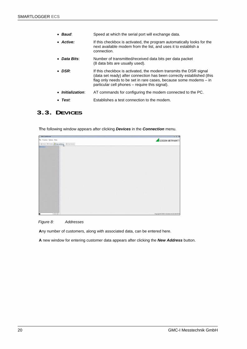
33..33.. DDEEVVIICCEESS The following window appears after clicking Devices in the Connection menu.
Figure 8: Addresses
Any number of customers, along with associated data, can be entered here. A new window for entering customer data appears after clicking the New Address button.
SMARTLOGGER ECS
GMC-I Messtechnik GmbH 21
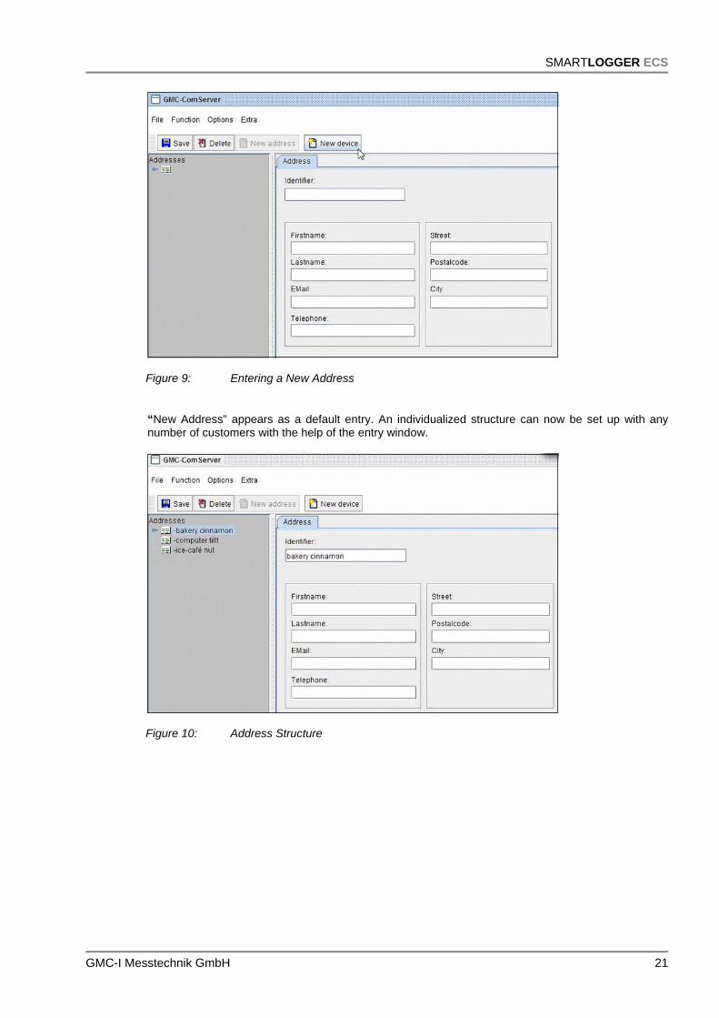
Figure 9: Entering a New Address
“New Address” appears as a default entry. An individualized structure can now be set up with any number of customers with the help of the entry window.
Figure 10: Address Structure
SMARTLOGGER ECS
22 GMC-I Messtechnik GmbH
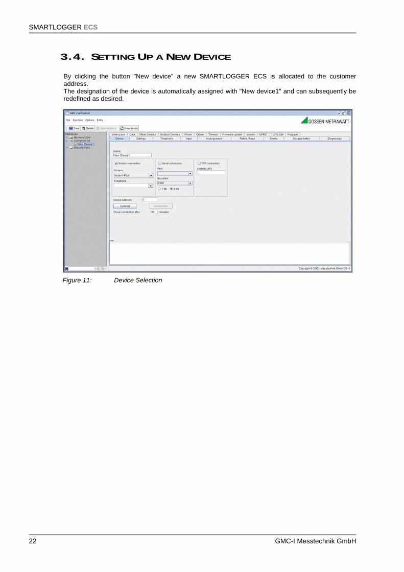
33..44.. SSEETTTTIINNGG UUPP AA NNEEWW DDEEVVIICCEE By clicking the button "New device" a new SMARTLOGGER ECS is allocated to the customer address. The designation of the device is automatically assigned with "New device1" and can subsequently be redefined as desired.
Figure 11: Device Selection

SMARTLOGGER ECS
GMC-I Messtechnik GmbH 23
Location-specific data for the device can be entered to the Device tab. Name: freely selectable device designation, 30 characters (initially, the new
device is given the designation "New device1")
Modem connection: Connection established via analog, ISDN or GSM modem
Modem: Modem by means of which connection will be established
Phone no.: Phone number of the SMARTLOGGER ECS
Serial connection: Direct connection via a serial cable connected to the device, or indirect connection via a virtual serial port which must be set up previously
Port: COM port which is connected to the device
Baud: Selection of a valid baud rate A transmission speed of 9600 baud is required in order to establish connection with the SMARTLOGGER ECS.
Bits: Select the number of data bits per data packet. 8 bits are required in order to establish connection with the SMARTLOGGER ECS.
TCP connection: Establish connection via the Ethernet network (TCP/IP)
Address (IP): Valid IP address of the SMARTLOGGER ECS plus port number, for example: IP: 123.456.789.100, port: 10001 => entry: 123.456.789.100:10001
Device address: Address of the device within a range of 1 to 31
Connect: Establish connection to the SMARTLOGGER ECS.
Depending on the type of connection, the connect procedure can be observed in the information window: Modem connection:
The dial-up procedure can be observed. As soon as connection has been established, “connected” appears at the window. The software is now connected with the internal modem at the SMARTLOGGER ECS. Serial and TCP/IP connection: As soon as connection has been established, “open serial” appears at the window. The software checks communication up through the interface.
Disconnect: End connection
End connection automatically after x min
Number of minutes after which connection to the device is automatically ended. If a “0” is entered, connection is not ended automatically.
After connection to the SMARTLOGGER ECS has been established, device parameters can be configured.

SMARTLOGGER ECS
24 GMC-I Messtechnik GmbH
33..55.. PPAARRAAMMEETTEERRSS CCOONNFFIIGGUURRAATTIIOONN Within the individual parameters configuration dialog boxes, values can be read out by clicking the Read button or, if permissible, transferred to the device by clicking the Write button. ATTENTION: Always read out currently selected parameter settings before
reconfiguring the device! 3.5.1. SSEETTTTIINNGGSS Parameters configuration is started by clicking the Settings tab:
Figure 12: Settings Tab Version: Version number of the device
Device address: Unique device ID number within a range of 1 to 31
Designation: Device designation, name, 30 characters
Serial no.: Serial number assigned by the manufacturer
Current device time: Internal clock time at the device (if date and time are set very accurately at the PC, device time can be set directly by clicking the Write PC time button.
First period value / last period value Date of the first and last period values stored to the device
Measuring period: Measuring period duration in minutes (memory cycles)
CAUTION: If this value is changed, all saved period values are deleted.

SMARTLOGGER ECS
GMC-I Messtechnik GmbH 25
3.5.2. PPHHOONNEE Basic settings required for the fault messaging function at the SMARTLOGGER ECS are entered to the Phone tab.
Figure 13: Phone Tab The following type of fault message transmission is used: Stand-alone – operation with GSM engine (SMS) In this operating mode, the SMARTLOGGER ECS dials a preprogrammed number when a fault occurs and sends a fault message as an SMS. There are two different alarm procedures:
Alarm procedure 1 – without acknowledgment Alarm procedure 2 – with acknowledgment
Alarm Procedure 1 – Without Acknowledgment In this case, no acknowledgment text is read out, i.e. the field remains blank. All SMS messages (including OK messages) are sent, one after the other, to all phone numbers. Alarm Procedure 2 – With Acknowledgment In this case, an acknowledgment text is read out, with which the recipient can acknowledge receipt of the fault message. The SMS message is initially sent to the first phone number only. If no return SMS is received within 10 minutes containing exactly the same acknowledgment text as was sent to the recipient, the next phone number is called and so forth (escalation procedure). All further messages are sent to the participant (phone number) from which the first return SMS was received. The alarm system is reset each day at midnight, i.e. fault messaging mechanisms are returned to their initial values (phone number 1 is notified first).

SMARTLOGGER ECS
26 GMC-I Messtechnik GmbH
The following fields are used in order to configure alarm procedure parameters: Phones 1 to 3
Phone numbers, to which an SMS should be sent in the event of a fault, can be entered to the first three entry fields. As a rule, these are cell phone numbers. Acknowledgment text
Text by means of which the recipient can acknowledge receipt of the fault message and acceptance of responsibility. Phone 4
The fourth field offers two possible options: As an alternative to entering a phone number, the “Send e-mail” option can be selected. Phone number In addition to the 3 previous phone numbers, a fourth is entered to this field. Send e-mail (SMS as e-mail) In addition to sending fault messages via SMS, they can also be sent to an e-mail address. The address is entered to the field which is provided for this purpose. IMPORTANT: The @ symbol must be replaced with an asterisk (*) in the e-mail
address.
Example: info*my_company.com NOTE: A phone number must be entered here in addition to an e-mail address.
This (abbreviated dialing) number is specified by the respective cell phone service provider. For example, the D1 abbreviated dialing number specified by T-Mobile is 8000. It’s only possible to send an SMS as an e-mail in combination with this number.

SMARTLOGGER ECS
GMC-I Messtechnik GmbH 27
Figure 14: Send e-mail The following list includes the relevant abbreviated dialing numbers for the usual cell phone service providers (revision level: 8 December 2008): D1 T-Mobile Abbreviated dialing number: 8000
D2 Vodafone Abbreviated dialing number: 3400
E-plus Abbreviated dialing number: 7676245
O2 Germany Abbreviated dialing number: 6245
Status message interval
Interval in days (0 to 30) at which the SMARTLOGGER ECS transmits a status message Send SMS at
Time of day at which the status message is sent Status text
The text to be sent, 30 characters

SMARTLOGGER ECS
28 GMC-I Messtechnik GmbH
3.5.3. IINNPPUUTTSS The parameters for the inputs at the SMARTLOGGER ECS are configured in the Inputs tab.
Figure 15: Inputs Tab 4 internal input channels are configured in the table, as well as the number of external inputs in accordance with the housing layout:
No.: Input number assigned by the system
Name: Freely selectable input designation, 30 characters
Mode:
NO – contact is open in the neutral position (normally open)
NC – contact is closed in the neutral position (normally closed)
Status: Contact status display
LED: Visual contact status indication
Inbound delay: Duration in seconds for which the fault must persist before an “inbound” fault message is sent
Outbound delay: Duration in seconds within which the fault must cease before an “outbound” fault message is sent
Alarm text: The transmitted fault message (only in combination with a text entry)
SMARTLOGGER ECS
GMC-I Messtechnik GmbH 29
Log: Flag indicating whether or not input values/states should be stored to memory (data logger function). In the case of pulse meters, for example, data are stored to memory for subsequent evaluation.
Type:
Input type:
Pulse counter: Input is used to acquire load profiles
Fault message: Input for acquiring fault messages
Timer: Operating minutes counter, number of minutes during which the channel is active
3.5.4. AANNAALLOOGG SSEENNSSOORRSS
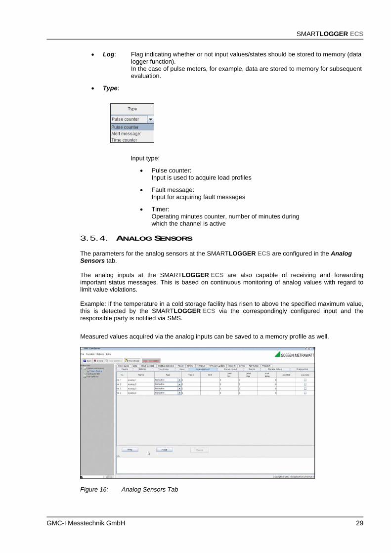
The parameters for the analog sensors at the SMARTLOGGER ECS are configured in the Analog Sensors tab. The analog inputs at the SMARTLOGGER ECS are also capable of receiving and forwarding important status messages. This is based on continuous monitoring of analog values with regard to limit value violations. Example: If the temperature in a cold storage facility has risen to above the specified maximum value, this is detected by the SMARTLOGGER ECS via the correspondingly configured input and the responsible party is notified via SMS.
Measured values acquired via the analog inputs can be saved to a memory profile as well.
Figure 16: Analog Sensors Tab

SMARTLOGGER ECS
30 GMC-I Messtechnik GmbH
4 internal, analog input channels are configured in the table, as well as the number of external inputs in accordance with the housing layout:
No.: Input number assigned by the system
Name: Freely selectable input designation, 30 characters
Type: Input type
Inactive: Input is not active
0 - 10 V: Standard 0 to 10 V signal is read out for conversion to a value
0 - 20 mA: Standard 0 to 20 mA signal is read out for conversion to a value
Temperature in °C: Temperature measurement by means of a sensor within a measuring range of -25 to 125° C
Fill-level as %: Fill-level measurement
Atmospheric humidity: Humidity measurement
Water sensor: Water sensor connected
Value: Momentary measured analog value
Unit of measure: Text field for unit of measure for the analog value, dictated by type, 30 characters
Lower limit value: Lower limit value for monitoring the analog value
Upper limit value: Upper limit value for monitoring the analog value
Alarm delay: Duration in seconds for which the limit value violation must persistbefore a fault message is sent
Alarm text: The transmitted fault message (only in combination with a text entry)
Log: Flag indicating whether or not input values/states should be stored to memory (data logger function)
NOTE: Settings in the Analog Sensors tab must necessarily be matched to the utilized
hardware, because the device cannot otherwise function correctly!

SMARTLOGGER ECS
GMC-I Messtechnik GmbH 31
3.5.5. RREELLAAYYSS The Relays tab provides functions for monitoring and switching the relays at the SMARTLOGGER ECS.
Figure 17: Relays Tab Differentiation is made amongst 4 internal relays and up to 8 optional, externally connected relays. Each respective relay for devices using up to 230 V can be remote switched at the SMARTLOGGER ECS after activating Open or Closed. The Switch button is clicked to this end. The current statuses of all available relays are displayed after clicking the Read button. All device functions can be returned to their original states by clicking the Device Reset button.

SMARTLOGGER ECS
32 GMC-I Messtechnik GmbH
3.5.6. EEVVEENNTTSS Stored (logged) events can be read out of memory and viewed in the Events tab.
Figure 18: Events Tab All status changes are written to an events memory by the SMARTLOGGER ECS. The following events are documented:
Error inputs
Analog Inputs
Power failure
Operation (power on/off)
From / to: Time span to be covered by the events list generated by the device
The read operation is started by clicking the Read button. The read operation can be interrupted by clicking the Abort button. Data which have been read out can be saved to a file which can be opened in Excel by clicking the Save button.

SMARTLOGGER ECS
GMC-I Messtechnik GmbH 33
3.5.7. RREECCHHAARRGGEEAABBLLEE BBAATTTTEERRYY The SMARTLOGGER ECS allows for the read-out of an alarm message when operating power is drawn from the rechargeable battery. This function can be configured in the Battery tab.
Figure 19: Battery Tab
Voltage: Momentary battery voltage in mV
Alarm delay: Duration in seconds for which power failure must persist before a fault message is sent
Alarm text: The transmitted fault message, 30 characters
3.5.8. DDIIAAGGNNOOSSIISS A device assessment can be executed in the Diagnosis tab.
Figure 20: Diagnosis Tab All fault messages generated for the device are saved to the internal status register at the SMARTLOGGER ECS.

SMARTLOGGER ECS
34 GMC-I Messtechnik GmbH
Read: Status query, polling of the status register
Clear device status: Sets device status to 0, clears all status registers
3.5.9. CCOOUUNNTTIINNGG PPUULLSSEESS Momentary meter readings for the pulse input channels can be displayed in the Counting Pulses tab.
Figure 21: Counting Pulses Tab
Read: One-time only read-out of meter readings
Read Sec.: Cyclical read-out time interval
Start: Cyclical read-out
Clear meter readings: Set all meter readings to 0

SMARTLOGGER ECS
GMC-I Messtechnik GmbH 35
3.5.10. LLOOAADD PPRROOFFIILLEE Data display for all 8 channels is possible in the Load Profile tab.
Figure 22: Load Profile Tab
From / to: Time span to be covered by the load profile generated by the device
The read operation is started by clicking the Read button. The read operation can be interrupted by clicking the Abort button.
This tab includes a special function that makes it possible to export data which has been read out for subsequent visualization. The data can be visualized in, for example, Microsoft Excel. The procedure is as follows: Read out the data.
Right click into the data table.
A selection window appears.
You can now choose either “Copy” or “Save”.
Start Excel.
Open the data record or paste to Excel via the clipboard.
Imported data records can now be processed – for example converted in to a bar graph diagram.
In this way, consumption and temperature profiles, as well analog data, can be visualized.

SMARTLOGGER ECS
36 GMC-I Messtechnik GmbH
3.5.11. MM--BBUUSS DDEEVVIICCEESS When the M-Bus Devices tab is selected, the M-Bus configuration is read out automatically.
Figure 23: M-Bus Devices Tab
Name: Freely selectable name for the M-Bus device
Address: Current device address within a range of 0 to 254
New address: New address which will replace the old one within a range of 0 to 254
Change: Change the address
Manufacturer: Displays the manufacturer of the device
Read-out cycle: Time interval in minutes for reading out M-Bus data
Baud: Momentary baud rate for communication with the M-Bus device
New baud rate: New baud rate which will replace the old one
Change: Change the baud rate
The M-Bus device’s channels are displayed in the table. (Note: All interconnected M-Bus devices whose data need to be logged have to have the same baud rate!)
No.: Channel number
Name: Channel designation
Date: If the channel contains a date, the stored date is displayed here.
Value: If the channel contains a value, the stored value is displayed here.

SMARTLOGGER ECS
GMC-I Messtechnik GmbH 37
The following hexadecimal entries offer protocol-specific information required for interpreting values which have been read out.
DIF: Data information field
DIFE: Data information field extended
VIF: Value information field
VIFE: Value information field extended
Log: Flag indicating whether or not the value should be stored to memory
3.5.12. MMOODD--BBUUSS DDEEVVIICCEESS When the Mod-Bus Devices tab is selected, the Mod-Bus configuration is read out automatically.
Figure 24: Selecting the Mod-Bus Devices Tab
3.5.13. FFIIRRMMWWAARREE UUPPDDAATTEE An updated software version can be uploaded to the SMARTLOGGER ECS with the help of the Firmware Update tab. The update can be executed by GMC-I Messtechnik employees, or by the user.
Figure 25: Updating the Software Version

SMARTLOGGER ECS
38 GMC-I Messtechnik GmbH
3.5.14. MMOODDEEMM If an integrated GSM modem is available, certain SMARTLOGGER ECS functions can be remote controlled and values can be queried via SMS. The SMS texts (flags) required to this end can be set up with the help of the Modem tab.
Figure 26: Modem Tab
Account balance: Display of current SIM card credit, for example “4.63”: The SIM card has a current balance of €4.63.
SMS text, check account: Text to be sent in order to query the current account balance For example, Send SMS “Account balance”
Response: “Your balance is: €4.63”
SMS text, increase balance: Text to be sent along with the credit number in order to load a prepaid card
For example Send SMS “Load account #<no.>” No. – cash number for
loading a prepaid card
SMS text, switch relay on: Text to be sent along with the relay number, in order to switch a relay on
For example Send SMS “Switch on#<no.>” No. – relay number
SMS text, switch relay off: Text to be sent along with the relay number, in order to switch a
relay off
For example Send SMS “Switch off#<no.>” No. – relay number

SMARTLOGGER ECS
GMC-I Messtechnik GmbH 39
SMS Text, status query: Text to be sent in order to query the device status The response contains information regarding the current status of the SMARTLOGGER ECS (input statuses, relay statuses, account balance).
For example Send SMS “Status” Response “Status
Inputs 1:on 2:off 3:off 4:on Outputs 1:off 2:on 3:off 4:on 4.63"
Modem type: Display of the current modem type
Product Support
If required please contact:
GMC-I Messtechnik GmbH Product Support Hotline Phone +49 911 8602-0 Fax +49 911 8602-709 E-Mail [email protected]
Service Center
Repair and Replacement Parts Service Calibration Center * and Rental Instrument Service When you need service, please contact: GMC-I Service GmbH
Service Center Thomas-Mann-Strasse 20 90471 Nürnberg • Germany Phone +49 911 817718-0 Fax +49 911 817718-253 E-Mail [email protected] www.gmci-service.com
This address is only valid in Germany. Please contact our representatives or subsidiaries for service in other countries.
* Calibration Laboratory for Electrical Quantities DKD – K – 19701 accredited per DIN EN ISO/IEC 17025:2005 Accredited measured quantities: direct voltage, direct current -values, DC -resistance, -alternating voltage, -alternating current -values, AC active power, AC apparent power, DC power, -capacitance, -frequency and temperature
________________________________________________________________________________________________ Edited in Germany • Subject to change without notice • A pdf version is available on the Internet
GMC-I Messtechnik GmbH Südwestpark 15 90449 Nürnberg• Germany
Phone +49 911 8602-111 Fax +49 911 8602-777 E-mail [email protected] www.gossenmetrawatt.com