SMARTLINX INTERFACE MODULE FOR PROFIBUS-DP · PDF fileInstruction Manual December 2001 MODULE...
46
Instruction Manual December 2001 SMARTLINX INTERFACE MODULE FOR PROFIBUS-DP SMARTLINX INTERFACE MODULE R
Transcript of SMARTLINX INTERFACE MODULE FOR PROFIBUS-DP · PDF fileInstruction Manual December 2001 MODULE...

Instruction Manual December 2001
SM
AR
TL
INX
INT
ER
FA
CE
MO
DU
LE
FOR PROFIBUS-DP
SMARTLINX INTERFACE MODULE
R

© Siemens Milltronics Process Instruments Inc. 2001
Safety Guidelines
Warning notices must be observed to ensure personal safety as well as that of others, and toprotect the product and the connected equipment. These warning notices are accompaniedby a clarification of the level of caution to be observed.
Qualified Personnel
This device/system may only be set up and operated in conjunction with this manual.Qualified personnel are only authorized to install and operate this equipment in accordancewith established safety practices and standards.
Warning: This product can only function properly and safely if it is correctly transported,stored, installed, set up, operated, and maintained.
Note: Always use product in accordance with specifications.
Copyright Siemens Milltronics ProcessInstruments Inc. 2001. All Rights Reserved
Disclaimer of Liability
This document is available in bound version and inelectronic version. We encourage users topurchase authorized bound manuals, or to viewelectronic versions as designed and authored bySiemens Milltronics Process Instruments Inc.Siemens Milltronics Process Instruments Inc. willnot be responsible for the contents of partial orwhole reproductions of either bound or electronicversions.
While we have verified the contents ofthis manual for agreement with theinstrumentation described, variationsremain possible. Thus we cannotguarantee full agreement. Thecontents of this manual are regularlyreviewed and corrections are includedin subsequent editions. We welcomeall suggestions for improvement.
Technical data subject to change.
MILLTRONICS®is a registered trademark of Siemens Milltronics Process Instruments Inc.
Contact SMPI Technical Publications at the following address:
Technical PublicationsSiemens Milltronics Process Instruments Inc.1954 Technology Drive, P.O. Box 4225Peterborough, Ontario, Canada, K9J 7B1Email: [email protected]
For the library of SMPI instruction manuals, visit our Web site: www.milltronics.com

7ML19981AQ02 SmartLinx® Profibus-DP 3
Table of Contents
Specifications ....................................................................................... 5
About SmartLinx® Profibus DP........................................................ 7About this Manual........................................................................ 7About this Module........................................................................ 8
Installation ............................................................................................ 9Compatibility.................................................................................... 9Address ......................................................................................... 11Baud Rate ..................................................................................... 11Termination Switch........................................................................ 11Cable Connector ........................................................................... 12
Operation ............................................................................................ 14Error Status LEDs......................................................................... 14Operation LED............................................................................... 15
Communication Setup ....................................................................... 16GSD Files...................................................................................... 16Configuring the Master .................................................................. 16
Application Layer ............................................................................... 18Parameter Indexes ........................................................................ 18Data Access Methods ................................................................... 19Data Map....................................................................................... 23Data Map....................................................................................... 29Data Types.................................................................................... 38
Troubleshooting ................................................................................. 42Generally....................................................................................... 42
Index.................................................................................................... 44

4 SmartLinx® Profibus-DP 7ML19981AQ02

7ML19981AQ02 SmartLinx® Profibus-DP 5
Specifications
SpecificationsApplication:
• compatible with a master device on a Profibus busCompatible Instruments:
• AiRanger XPL Plus• AiRanger DPL Plus• AiRanger SPL• CraneRanger• InterRanger DPS 300• EnviroRanger ERS 500• Accumass BW500• Accumass SF500• MultiRanger 100/200• HydroRanger 200
Communication Settings:• baud rate: 9.6 Kbaud to 12 Mbaud, automatically detected
Connection:• varies by Milltronics SmartLinx® instrument, (see page 12)
Termination:• switch selectable, open or special active termination as per Profibus
specification (see Termination Switch on page 11).Cable:
• Belden Profibus cable 3079A, or equivalent

6 SmartLinx® Profibus-DP 7ML19981AQ02
Spec
ifica
tions

7ML19981AQ02 SmartLinx® Profibus-DP 7
About this
About SmartLinx® Profibus DPAbout this Manual
This manual provides you with the information required to successfully installand connect a Milltronics SmartLinx® Profibus-DP module and set it up forcommunication with a master device on a Profibus-DP network.
This manual is targeted at a technical audience in the industrialcommunications field with a sound working knowledge of Profibus-DP.
Profibus is an open standard controlled by Profibus industry groupsworldwide. More information is available on the web site atwww.profibus.com.
Note:Milltronics does not own the Profibus-DP protocol. All informationregarding that protocol is subject to change without notice.

8 SmartLinx® Profibus-DP 7ML19981AQ02
Abo
ut th
is
About this ModuleThe Milltronics SmartLinx Profibus-DP module is a plug-in communicationscard designed to interface a Milltronics SmartLinx-compatible instrument to aProfibus-DP network.
Only those instruments which support the Profibus-DP protocol can use thiscard. See Compatibility on page 9 for a list of compatible MilltronicsSmartLinx instruments.
PLC master
Profibus-DP at 9.6Kbaud to 12Mbaud
Milltronicsinstrument
monitoredprocess

7ML19981AQ02 SmartLinx® Profibus-DP 9
Installation
InstallationThe SmartLinx module is either shipped installed in the Milltronics instrumentor separately for on-site installation. Refer to the manual of your Milltronicsinstrument for details on module location and physical installation.
CompatibilityAll available SmartLinx card configurations are shown here for reference.
The card shown below is compatible with the following Milltronics units:• AiRanger XPL Plus• AiRanger DPL Plus• AiRanger SPL• CraneRanger• InterRanger DPS 300
addressswitches
mounting hole
module connector (underside, 32-pin) to Milltronics host
terminal block, removable
termination switch
status LEDs
mounting hole

10 SmartLinx® Profibus-DP 7ML19981AQ02
Inst
alla
tion
The cards shown below are compatible with the following Milltronics units:• EnviroRanger ERS 500• Accumass BW500• Accumass SF500
• MultiRanger 100/200• HydroRanger 200
EnviroRanger Rack or Panel
EnviroRanger Wallmount , Accumass BW 500, Accumass SF500,MultiRanger 100/200, HydroRanger 200
Note:Correct cable routing is important for electromagnetic noise suppression.Follow the routing instructions contained in the Accumass BW500 manual.
address switches
mounting hole
module connector (underside, 34-pin) to Milltronics host
module connector (underside, 10-pin)
termination switchstatus LEDs
mounting hole operation LED
address switches
mounting hole
module connector (underside, 34-pin) to Milltronics host
terminal block, removabletermination switch
status LEDs
mounting hole operation LED

7ML19981AQ02 SmartLinx® Profibus-DP 11
Installation
AddressSet the two rotary switches to the address for this slave.
Use a slave address switch in the range 03 to 99.This example shows the value 06.
Baud RateThe module configures itself to the correct baud rate for the Profibus-DPnetwork.
Termination SwitchTermination Setting Switch Position
open (not used) off
on
Profibus DP requires termination of the bus at both end points, see theProfibus DP specifications for details.
+5V
Line A
Line B
GND
390Ω
220Ω
390Ω

12 SmartLinx® Profibus-DP 7ML19981AQ02
Inst
alla
tion
Cable ConnectorConnect using Belden Profibus cable 3079A or equivalent and terminateaccording to Profibus-DP specification and conventions.
Notes:• Use only A-line and B-line for most applications.• The +5V bus (Vcc) and Ground (GND) terminals are used to pull-up or
pull-down the bus voltage, use only if required. See the RS-485specifications for details.
• Request to Send (RTS) is used in some equipment to determine thedirection of transmission, use only if required.
AiRanger Series, CraneRanger, InterRanger DPS 300
Note:To daisy-chain devices, connect the outgoing wires to terminals 6 and 7.
EnviroRanger ERS 500 (Rack or Panel mount)When using a SmartLinx card with the EnviroRanger (rack or panel mount)all wiring is made to the EnviroRanger terminal board. The Profibusconnections map to the EnviroRanger terminal board as shown:
EnviroRanger Connection65 Gnd_bus66 RTS68 A69 B71 V_bus +5V67 bus cable shield
bus
+5V
(Vcc
)
bus
grou
nd (G
ND
)
A-lin
e
B-lin
e
bus
shie
ld
A-lin
e
B-lin
e
bus
cabl
e sh
ield

7ML19981AQ02 SmartLinx® Profibus-DP 13
InstallationEnviroRanger ERS 500 (Wallmount), Accumass BW 500, Accumass SF500,MultiRanger 100/200, HydroRanger 200
Note:To daisy-chain devices with the BW500, connect both wires to the existingA-line and B-line terminals.
bus
+5V
(Vcc
)
bus
grou
nd (G
ND
)
A-lin
e
B-lin
e
bus
cabl
e sh
ield
RTS

14 SmartLinx® Profibus-DP 7ML19981AQ02
Ope
ratio
n
OperationCommunication on the Profibus-DP link is indicated by the SmartLinx LEDs.
Error Status LEDsAiRanger Series, CraneRanger, InterRanger DPS 300
Green LEDON module is operational
Green LEDON data is being exchangedOFF data is being exchanged
Red LEDON no communication between bus and
module / Bus errorOFF normal operation
EnviroRanger ERS 500, Accumass BW500, Accumass SF500,MultiRanger 100/200, HydroRanger 200
Not used OnlineGreen:
module is online
Diagnostics OfflineOff:
module is okRed (blinking):
module is in an error state.See the error descriptions(page 15) and use themaster to solve the problem.
Red:module is offline and nocommunication is possible

7ML19981AQ02 SmartLinx® Profibus-DP 15
Operation
Error Conditions1Hz Error in Configuration
Indicates that the I/O length variable set during initialization is not equal tothe length set during configuration of the network. See Configuring theMaster on page 16 for lengths supported by the SmartLinx module and seeyour PLC documentation for setting the I/O length variable.
2Hz Error in User Parameter DataIndicates that the length and / or contents of the user parameter data setduring initialization of the module is not equal to the length and / or contentsset during configuration of the network. See Configuring the Master on page16 for supported lengths.
4Hz Error in InitializationConsult your Milltronics representative.
Operation LEDEnviroRanger ERS 500, Accumass BW500, Accumass SF500,MultiRanger 100/200, HydroRanger 200 only
LED• blinks orange as the module is initialized• blinks green during normal operation

16 SmartLinx® Profibus-DP 7ML19981AQ02
Com
mun
icat
ion
Setu
p
Communication SetupThe SmartLinx Profibus-DP module is a slave on the bus, and does not useany Milltronics instrument parameters for configuration. Set the rotaryswitches on the module to the desired slave address, other settings areprovided in the GSD file or are automatically detected.
GSD FilesProfibus master devices require a configuration file for each slave device onthe network. This file configures the master for the capabilities and limitationsof the slave. For the SmartLinx Profibus-DP module these files are:
• AiRanger Series: HMS-1002.GSD• BW500, SF500,
MultiRanger 100/200, HMS1003.GSDHydroRanger 200,ERS 500:
Both files are supplied on the floppy disk that is shipped with the module.
The file HMS-1002.GSD uses the manufacturers I.D. number of 1002hexadecimal (4,098 decimal). The file HMS1003.GSD uses themanufacturers I.D. number 1003 hexadecimal (4,099 decimal).
Configuring the MasterUse the configuration software (or any equivalent master commands) toconfigure the slave. Refer to the information that came with the Profibusmaster. The Milltronics instrument appears as a modular type slave, andshould be configured as shown below:
Warning:The size of the read and write blocks should exactly match thevalues given below or a bus fault may occur on some systems.
Level Products (includes AiRanger Series, ERS 500, MultiRanger 100/200,HydroRanger 200)
• 84 bytes input (see Write Block on page 23).• 26 bytes output (see Read on page 26).• read and write data as 16-bit words (see Data Types on page 38).
Mass Dynamics Products (includes BW500, SF500)• 62 bytes input (see Write on page 29)• 38 bytes output (see Read on page 33)• read and write data as 16-bit words (see Data Types on page 38)

7ML19981AQ02 SmartLinx® Profibus-DP 17
Com
munication Setup
If your Profibus master is not capable of handling the block sizes listedabove then use multiple, smaller blocks.
For exampleAn S5-115U with an IM 308C master would use the following:
For Level products:Inputs: 3 address blocks of 16, 16, and 10 wordsOutputs: 1 address block of 13 words
For Mass Dynamics products:Inputs: 2 address blocks of 16 and 15 wordsOutputs: 2 address blocks of 16 and 3 words
Notes:• Data is read and written with the most significant byte (MSB) first.• The address and size of the reads and writes in the PLC must match
the Milltronics device (see above).• Profibus-DP diagnostic bytes are not supported, however, some
diagnostic information can be accessed via reading and writing thedata areas. See Application Layer on page 18.
Baud RateThe SmartLinx Profibus module automatically configures itself to the baudrate used on the bus.
Follow the Profibus guidelines with regards to bus length and baud rate.

18 SmartLinx® Profibus-DP 7ML19981AQ02
App
licat
ion
Laye
r Application LayerThis section describes the meaning of data read from and written to theMilltronics SmartLinx instrument slave memory. The output words (PLCmaster write operation) and input words (PLC master read operation) aredescribed in the Data Map for Level Products on page 23 and the Data Mapfor Mass Dynamic Products on page 29.
Note:Parameter P999 (Master Reset) is not accessible via the SmartLinxinterface on Level products.
Parameter IndexesMost parameters used on Milltronics SmartLinx instruments are indexed.Indexing allows a parameter to relate to more than one input or output. Forexample, many parameters are indexed by measurement point while othersare indexed by relay output or discrete input.
Primary IndexAn index that relates to an input or output is called a Primary Index.
Examples of primary indexes are:P111[3] = 52 means:P111 (Relay Control Function) for relay 3 is set to value 52
Sometimes a parameter requires a second index to allow for multiple valueson an indexed input or output. For example a measurement point whichcalculates a reading on volume can require characterization breakpoints.These breakpoints are given on a secondary index (the primary index relatesto the transducer input).
On some older Milltronics products the primary index is called a point.
52

7ML19981AQ02 SmartLinx® Profibus-DP 19
Application Layer
Secondary IndexAn index that relates to a previously indexed parameter is called a secondaryindex.
Examples of secondary indexes are:P054[1,5] = 1.6m means:P054 (Breakpoint Levels) for breakpoint 5 on transducer 1 is set to 1.6m
The way that indexes are handled in the memory map depend on the dataaccess method used.
On some older Milltronics products the secondary index is called a mark.
Data Access MethodsThere are three different methods used in the memory mapping to giveaccess to the SmartLinx Instrument parameter table. They are:
• Direct Access• Multiple Parameter Access (MPA)• Single Parameter Access (SPA)
Direct AccessCertain values are mapped directly into words. These words can bemonitored continuously but they are not configurable.
1.6m
20 SmartLinx® Profibus-DP 7ML19981AQ02
App
licat
ion
Laye
r
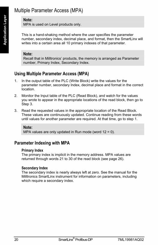
Multiple Parameter Access (MPA)Note:MPA is used on Level products only.
This is a hand-shaking method where the user specifies the parameternumber, secondary index, decimal place, and format, then the SmartLinx willwrites into a certain area all 10 primary indexes of that parameter.
Note:Recall that in Milltronics products, the memory is arranged as Parameternumber, Primary Index, Secondary Index.
Using Multiple Parameter Access (MPA)1. In the output table of the PLC (Write Block) write the values for the
parameter number, secondary Index, decimal place and format in the correctlocation.
2. Monitor the Input table of the PLC (Read Block), and watch for the valuesyou wrote to appear in the appropriate locations of the read block, then go toStep 3.
3. Read the requested values in the appropriate location of the Read Block.These values are continuously updated. Continue reading from these wordsuntil values for another parameter are required. At that time, go to step 1.
Note:MPA values are only updated in Run mode (word 12 = 0).
Parameter Indexing with MPAPrimary IndexThe primary index is implicit in the memory address. MPA values arereturned through words 21 to 30 of the read block (see page 26).
Secondary IndexThe secondary index is nearly always left at zero. See the manual for theMilltronics SmartLinx instrument for information on parameters, includingwhich require a secondary index.

7ML19981AQ02 SmartLinx® Profibus-DP 21
Application Layer
Single Parameter Access (SPA)Note:SPA is used on both Level and Mass Dynamics products.
This is a hand-shaking method where the PLC specifies:
• parameter number• primary index• secondary index• decimal place• format• read/write flag• value
With this method any value in the Milltronics product can be read or written.
Using Single Parameter Access (SPA)SPA allows continuous monitoring or demand programming of a parameter.
Reading a Parameter1. Set the Read/Write flag in the output table (Write Block) to 0, read.
2. Write the Parameter Number, Primary Index, Secondary Index, DecimalPlace and Format in the correct locations.
NoteIf there is no secondary index, then place a 0 in this location.
3. Monitor the Input table of the PLC (Read Block) and watch for the values youwrote to appear in the appropriate locations, then go to Step 4.
4. Read the requested parameter value in the Input table (Read Block). Thesevalues are continuously updated. Continue reading from these words untilvalues for other parameters are required. At that time, go back to step 1.
Writing a Parameter1. Set the Read/Write flag in the output table (Write Block) to 0, read.
2. Write the Parameter Number, Primary Index, Secondary Index, DecimalPlace and Format in the correct locations.
3. Write the new value of the parameter into the correct location of the outputmemory (Write Block)
4. Verify the unit is in program mode (not needed for BW500). For Level see bit10 of status word in Read Block.
5. If it is not in program mode, write a 1 to the operating mode word in theoutput memory (Write Block). Please note that this will only work if the wordis already a 0 (ie. it only works as a transition).

22 SmartLinx® Profibus-DP 7ML19981AQ02
App
licat
ion
Laye
r6. Set the Read / Write flag in the output table (Write Block) to a 1 write.
7. Monitor the Input table of the PLC (read block) and watch for the values youwrote to appear in the appropriate locations.
8. Set Read / Write flag back to 0.
9. Place unit in Run mode.
Note (does not apply to Accumass BW 500, Accumass SF500):Parameters can only be written in Program mode (word 12 = 1). If the hostinstrument is still in Run mode then any written values are ignored.

7ML19981AQ02 SmartLinx® Profibus-DP 23
Application Layer
Data MapLevel Products
This section describes the meaning of the data read from and written to theMilltronics SmartLinx instrument.
Refer to the PLC documentation on how to program reads and writes in yourPLC.
Write BlockWord Description Access Data Type0 measurement point on priority direct bitmapped1 parameter number integer2 parameter secondary index (mark) integer3 decimal place integer4 format
MPA
0/15 parameter number integer6 parameter primary index (point) integer7 parameter secondary index (mark) integer8 parameter value integer9 decimal place integer10 format 0/111 read/write flag
SPA
0/112 operating mode direct 0/1
Word 0: Point-on-PriorityBits 00-09 set the priority status of corresponding indexed points 1 to 10.
bit 09 08 07 06 05 04 03 02 01 00index 10 9 8 7 6 5 4 3 2 1
bit status 0 = normal1 = priority
In the example
bit 09 08 07 06 05 04 03 02 01 00index 0 0 0 0 0 0 0 1 0 1
points 3 and 1 are on priority scan. All other bits are reserved and contain 0.
If this word is used to control point-on-priority, then the Milltronics SmartLinxinstrument must be configured to permit this. Parameter P720 must be set to1 (manual, BIC-II or SmartLinx SPA) for each point to permit priority controlfor that point.

24 SmartLinx® Profibus-DP 7ML19981AQ02
App
licat
ion
Laye
rTo enable priority control for all indexed measurement points use SPA tostore 1 to parameter P720, index 0 (P720[0]).
Word 1: Parameter Number, MPASpecifies the parameter number for the returned values in words 21 to 30.See Read on page 26.
Word 2: Parameter Secondary Index, MPASpecifies the secondary index for the parameter specified by word 1. Thisword is ignored for parameters that dont use multiple indexes. SeeParameter Indexes on page 18 for more information.
Note:The Primary Index is implicit in the word location where word 21 = index 1and word 30 = index 10.
Word 3: Decimal Place, MPASpecifies the number of decimal places to shift the returned values. Thisaffects words 21 to 30.
Positive values indicate that the decimal place shifts to the left.
i.e. A 1 means that all returned values have the decimal place shifted 1space to the left and a returned value of 5,213 is interpreted as 521.3.
Negative values indicate that the decimal place shifts to the right.
i.e. If this word is -1, a returned value of 5,213 is interpreted as 52,130.
Word 4: Format, MPASets the format for the returned values in words 21 to 30.
0 = normal1 = percent
Word 5: Parameter, SPASpecifies the requested parameter number.
Word 6: Primary Index, SPASpecifies the primary index number for the parameter in word 5.
Word 7: Secondary Index, SPASpecifies the secondary index for the parameter in word 5. This word isignored for parameters that dont use multiple indexes. See ParameterIndexes on page 18 for more information.

7ML19981AQ02 SmartLinx® Profibus-DP 25
Application Layer
Word 8: Value, SPAThis word contains the value written to the specified parameter and index.The format of this word is specified by words 9 to 10.
To write a value, ensure word 11 = 1 and word 12 =1. See also: Data Typeson page 38.
Word 9: Decimal Place, SPAThis word specifies the number of decimal places for the value in word 8,and also for the parameter value returned in word 38.
Positive values indicate that the decimal place shifts to the left.
i.e. A 1 means that all returned values have the decimal place shifted 1space to the left and a returned value of 5,213 is interpreted as 521.3.
Negative values indicate that the decimal place shifts to the right.
i.e. If this word is -1, a returned value of 5,213 is interpreted as 52,130.
Word 10: Format, SPAThis word sets the format for the value in word 8.
0 = normal1 = percent
Word 11: Read/Write Flag, SPAThis word instructs the read/write application of word 8.
0 = read parameter as described by words 5, 6, 7, 9 and 10; word 8 ignored1 = set parameter to the value described by words 5 to 10
Word 12: Operating Mode, SPAThis word sets the operating mode of the Milltronics SmartLinx instrument.
The operating mode can get out of sync if the remote instrument resets backto run mode locally. This can happen due to a timeout or through localprogramming. The mode is always reported correctly through the Readblock. See bit 10 of Word 0: Instrument Status on page 26.
To reset the instrument to program mode you must write 0 to put theSmartLinx module back in sync with the instrument and then write 1 to setthe instrument to program mode.
0 = run mode1 = program mode

26 SmartLinx® Profibus-DP 7ML19981AQ02
App
licat
ion
Laye
r
Read BlockValues in words 0 to 20 are directly available, no write operation is requiredto request them.
Values in words 21 to 41 are determined by the write operation thatrequested them, either MPA or SPA. See Write Block on page 23.
Words Description Access Data Type0 instrument status bitmapped1-10 point reading integer11-20 point alarm and status
directbitmapped
21-30 returned values integer31 decimal place integer32 format 0/133 parameter number integer34 parameter secondary index
MPA
integer35 parameter integer36 parameter primary index integer37 parameter secondary index integer38 value integer39 decimal place integer40 format 0/141 read/write flag
SPA
0/1
Word 0: Instrument Statusbit description00 to 09: measurement point status
indicates the operation of measurement points 1 to 10.
bit 09 08 07 06 05 04 03 02 01 00index 10 9 8 7 6 5 4 3 2 1
0 operational1 non-operational
These bits consolidate the values from words 11 to 20, bits 00 to 03. If any ofthose bits are 1 (point non-operational) then the word 0 bit for that point isalso 1.
10: operating mode0 = Milltronics SmartLinx instrument in run mode1 = Milltronics SmartLinx instrument in program mode
11 to 15: reservedThese bits are reserved and set to 0.

7ML19981AQ02 SmartLinx® Profibus-DP 27
Application Layer
Words 1 to 10: Point ReadingThese words contain the value of parameter P920 (Reading) for points 1 to10, respectively. The reading is expressed as a percent of full scale,multiplied by 100, giving a range of 20,000 to 20,000 which corresponds to-200.00% to 200.00%. Refer to the Milltronics SmartLinx instrumentdocumentation for a definition of P920.
NoteThese values may contain numeric level data for inoperative ormalfunctioning points refer to read word 0, and read words 11 to 20 forthe actual operational status of the measurement points.
Words 11 to 20: Point Alarm and StatusThese words contain the corresponding alarm and status bits for indexedmeasurement points 1 to 10, respectively.
Bit status:0 = false1 = true
Bit description00 point not in service01 point failsafe timer expired02 point failed (cable shorted, open, or transceiver problem)03 point temperature sensor failed04 to 12 reserved for future use13 level emptying14 level filling15 scan mode priority
Words 21 to 30: Returned Values, MPAThese words contain values requested by writing to words 1 to 4. The type ofdata and format are specified with that request, and returned in blocktransfer read words 31 to 34.
Word 31: Decimal Place, MPAThis word specifies the number of decimal places in each of the returnedvalues in words 21 to 30.
Positive values indicate that the decimal place shifts to the left.
i.e. A 1 means that all returned values have the decimal place shifted 1space to the left and a returned value of 5,213 is interpreted as 521.3.
Negative values indicate that the decimal place shifts to the right.
i.e. If this word is -1, a returned value of 5,213 is interpreted as 52,130.

28 SmartLinx® Profibus-DP 7ML19981AQ02
App
licat
ion
Laye
rWord 32: Format, MPA
This word sets the format for the returned values.
bit status description0 normal1 percent
Note:When the format is selected as percent the decimal place value (word 3of the write block) is ignored and two decimal places are always used. Forexample, a value of 5947 represents 59.47%.
Words 33 and 34: Parameter Number and Secondary Index, MPAThese words contain the last values written to write block words 1 and 2,respectively. These words indicate what information is contained in readblock words 21 to 30. These words are provided since there can be a delaybetween writing a request, and the appearance of the requested values.
Use these words as an indicator that the requested information is updated.
Words 35 to 37 and 39 to 41: Parameter Number / Primary Index /Secondary Index and Decimal Place / Format / Read Write Flag, SPA
These words contain the last values written to words 5 to 7 and 9 to 11 of thewrite block. They confirm that the parameter value has been written. Thesewords are not updated until the value has been successfully transferred andstored in the Milltronics SmartLinx instrument.
See write formats on page 24 for details.
Word 38: Value, SPAThis word contains the current value of the parameter identified by words 35to 37 and 39 to 40, regardless of the value of word 11 (write flag).
If this value does not change when a new value is written to word 8(Parameter Value) then check the following:
1. If words 5 to 7 and 9 to 10 do not match read 35 to 37 and 39 to 40 then theinstrument hasnt responded yet.
2. If words 5 to 7 and 9 to 10 do match read 35 to 37 and 39 to 40 then theparameter value wasnt updated. Check that the Milltronics SmartLinxinstrument is in program mode and that the program lock (P000) is not onand try again.
7ML19981AQ02 SmartLinx® Profibus-DP 29
Application Layer
Data MapMass Dynamics Products
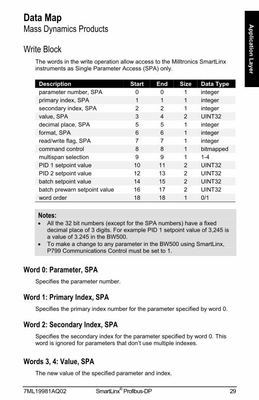
Write BlockThe words in the write operation allow access to the Milltronics SmartLinxinstruments as Single Parameter Access (SPA) only.
Description Start End Size Data Typeparameter number, SPA 0 0 1 integerprimary index, SPA 1 1 1 integersecondary index, SPA 2 2 1 integervalue, SPA 3 4 2 UINT32decimal place, SPA 5 5 1 integerformat, SPA 6 6 1 integerread/write flag, SPA 7 7 1 integercommand control 8 8 1 bitmappedmultispan selection 9 9 1 1-4PID 1 setpoint value 10 11 2 UINT32PID 2 setpoint value 12 13 2 UINT32batch setpoint value 14 15 2 UINT32batch prewarn setpoint value 16 17 2 UINT32word order 18 18 1 0/1
Notes:• All the 32 bit numbers (except for the SPA numbers) have a fixed
decimal place of 3 digits. For example PID 1 setpoint value of 3,245 isa value of 3.245 in the BW500.
• To make a change to any parameter in the BW500 using SmartLinx,P799 Communications Control must be set to 1.
Word 0: Parameter, SPASpecifies the parameter number.
Word 1: Primary Index, SPASpecifies the primary index number for the parameter specified by word 0.
Word 2: Secondary Index, SPASpecifies the secondary index for the parameter specified by word 0. Thisword is ignored for parameters that dont use multiple indexes.
Words 3, 4: Value, SPAThe new value of the specified parameter and index.
30 SmartLinx® Profibus-DP 7ML19981AQ02
App
licat
ion
Laye
rWord 5: Decimal Place, SPA
This word specifies the number of decimal places for the value in words 3 and 4.
Positive values indicate that the decimal place shifts to the left.
i.e. A 1 means that all returned values have the decimal place shifted 1space to the left and a returned value of 5,213 is interpreted as 521.3.
Negative values indicate that the decimal place shifts to the right.
i.e. If this word is -1, a returned value of 5,213 is interpreted as 52,130.
Word 6: Format, SPAThis word is always 0.
Word 7: Read / Write Flag, SPAThis word determines whether the instrument will allow parameter values tobe written.
0 = read1 = write
Word 8: Command Control, Operational CommandsThe command control word is used to control the unit. Each bit gives accessto a command or state as if the operator was using the keypad.
Bits initiating a command (7 to 12) must change state in order to cause thecommand to begin. For example, to reset totalizer 1, Bit 9 must be set to 0,then changed to 1. It can stay set or clear for any period.

7ML19981AQ02 SmartLinx® Profibus-DP 31
Application Layer
Bit # Description Bit Clear (0) Bit Set (1)00 PID 1 mode manual auto01 PID 1 freeze no yes02 PID 1 setpoint source local remote03 PID 2 mode manual auto04 PID 2 freeze no yes05 PID 2 setpoint source local remote06 zero no change start07 span no change start08 reset totalizer 1 no change reset09 reset totalizer 2 no change reset10 reset batch totalizer no change reset11 print print12 reserved13 reserved14 reserved15 reserved
Bit 00 and 03: PID ModeSets the mode of PID control to either manual (output determined by P410 PID Manual) or auto (output determined by PID control in instrument).
Bit 02 and 05 Setpoint SourceControls the location of the setpoint. If it is set as local, then the setpointused is internal to the BW500. If the setpoint source is set to remote, thenthe setpoint is controlled by a mA input.
For setpoint control through communications this must be set to local.
Bit 01 and 04: FreezeSuspends PID function when PID Mode = 1 (auto) and holds the output atthe last value. PID functionality resumes when the freeze bit is cleared.
Bit 06: ZeroSets the zero point for calibration of the belt scale.
This is a momentary setting that must be reset to 0 once the input isaccepted. To check that the input was accepted read word 0, bit 7 (zero status)and ensure it shows a 1. Once it shows a 1 then reset this bit to 0.
Bit 07: SpanSets the span for calibration of the belt scale.
This is a momentary setting that must be reset to 0 once the input isaccepted. To check that the input was accepted read word 0, bit 8 (SpanStatus) and ensure it shows a 1. Once it shows a 1 then reset this bit to 0.
Bit 08: Reset Totalizer 1Causes the internal totalizer 1 to be reset to 0.

32 SmartLinx® Profibus-DP 7ML19981AQ02
App
licat
ion
Laye
rThis is a momentary setting that must be reset to 0 once the input isaccepted. To check that the input was accepted, read word 0, bit 9 (ResetTotalizer 1) and ensure it shows a 1. Once it shows a 1 then reset this bitto 0.
Bit 09: Reset Totalizer 2Causes the internal totalizer 2 to be reset to 0.
This is a momentary setting that must be reset to 0 once the input isaccepted. To check that the input was accepted read word 0, bit 10 (ResetTotalizer 2) and ensure it shows a 1. Once it shows a 1 then reset this bitto 0.
Bit 10: Reset Batch TotalizerCauses the batch totalizer to be reset to 0.
This is a momentary setting that must be reset to 0 once the input isaccepted. To check that the input was accepted read word 0, bit 11 (ResetBatch Totalizer) and ensure it shows a 1. Once it shows a 1 then resetthis bit to 0.
Bit 11: PrintStarts print operation. One of the communications ports on the BW500 mustbe configured for a printer.
This is a momentary setting that must be reset to 0 once the input isaccepted. To check that the input was accepted read word 0, bit 12 (Printing)and ensure it shows a 1. Once it shows a 1 then reset this bit to 0.
Word 9: Multispan SelectionSets the current span (1 to 4). Any parameters that relate to span will usethis value to determine which span is referenced. See the manual for theBW500 for more information on multispan.
Words 10 to 13: PID SetpointsContain the current setpoint values as P415 in the Accumass BW500.
To write these setpoints bits 02 and 05 in word 8 - Control must be set to local.
Words 14 and 15: Batch SetpointContain the current setpoint value as P564 in the Accumass BW500.
Words 16 and 17: Batch Prewarn SetpointContain the current setpoint value as P567 in the Accumass BW500.

7ML19981AQ02 SmartLinx® Profibus-DP 33
Application Layer
Word 18: Word OrderThis word controls which word comes first in the UINT32 integers. For avalue 0, the most significant word is given first. For a value 1, the leastsignificant word is given first.
0 MSW first1 LSW first
Read BlockValues returned in the words in the read are in response to the write to theMilltronics SmartLinx instrument.
Words 0 through 20 have values with fixed meanings and formats. Thismeans that you do not have to start communications with a write in order touse read, the data is always there.
Words 22 through 30 are values returned in response to writing words 2through 7 for Single Parameter Access (SPA).
Description Start End Size Typeinstrument status 0 0 1 bitmappedrate 1 2 2 UINT32load 3 4 2 UINT32speed 5 6 2 UINT32total 1 7 8 2 UINT32total 2 9 10 2 UINT32relay status 11 11 1 bitmappeddiscrete input status 12 12 1 bitmappedmultispan selection 13 13 1 integerPID 1 setpoint value 14 15 2 UINT32PID 2 setpoint value 16 17 2 UINT32batch setpoint value 18 19 2 UINT32batch prewarn setpoint value 20 21 2 UINT32parameter, SPA 22 22 1 integerprimary index, SPA 23 23 1 integersecondary index, SPA 24 24 1 integervalue, SPA 25 26 2 UINT32decimal place, SPA 27 27 1 integerformat, SPA 28 28 1 integerread / write flag, SPA 29 29 1 1/0word order 30 30 1 1/0
Word 0: Instrument StatusThis word is used to feed back the current operating state of the product.Each bit gives the state of different parts of the product, some mutuallyexclusive, others are not. The state should be checked to verify anyMilltronics SmartLinx instrument commands.

34 SmartLinx® Profibus-DP 7ML19981AQ02
App
licat
ion
Laye
rBit # Description Bit Clear (0) Bit Set (1)0 PID 1 mode manual auto1 PID 1 freeze no yes2 PID 1 setpoint source local remote3 PID 2 mode manual auto4 PID 2 freeze no yes5 PID 2 setpoint source local remote6 zero no in progress7 span no in progress8 reset totalizer 1 no change reset9 reset totalizer 2 no change reset10 reset batch totalizer no change reset11 printing not printing printing12 write privileges no yes13 system configured not configured run mode14 mode calibration mode run mode15 totalizing not totalizing totalizing
Bits 0 to 5: PID StatusThese bits give the status of the product. For example Bit 0 is the mode ofthe PID 1 controller (if used). It indicates whether the PID is in manual orauto modes.
Bit 6: Zero StatusIndicates whether the unit is currently performing a Zero calibration.
Bit 7: Span StatusIndicates whether the unit is currently performing a Span calibration.
Bits 8 to 11: Totalizer StatusIndicate 1 if the reset totalizer or print operations are taking place (theseare momentary and will only stay set for a very short period).
Bit 12: Write PrivilegesIndicates whether the PLC can write parameters/commands to the product. This is controlled by parameter P799. If 1, the PLC may change theMilltronics SmartLinx instruments parameters, if 0, it can only read.
Bit 13: Configuration StatusIndicates whether the unit is configured (all required parameters have beenentered).
Bit 14: Program ModeIndicates program (calibration) mode, 0 = program mode, 1 = run mode
Bit 15: Totalizing StatusIndicates whether the unit is totalizing.
7ML19981AQ02 SmartLinx® Profibus-DP 35
Application Layer
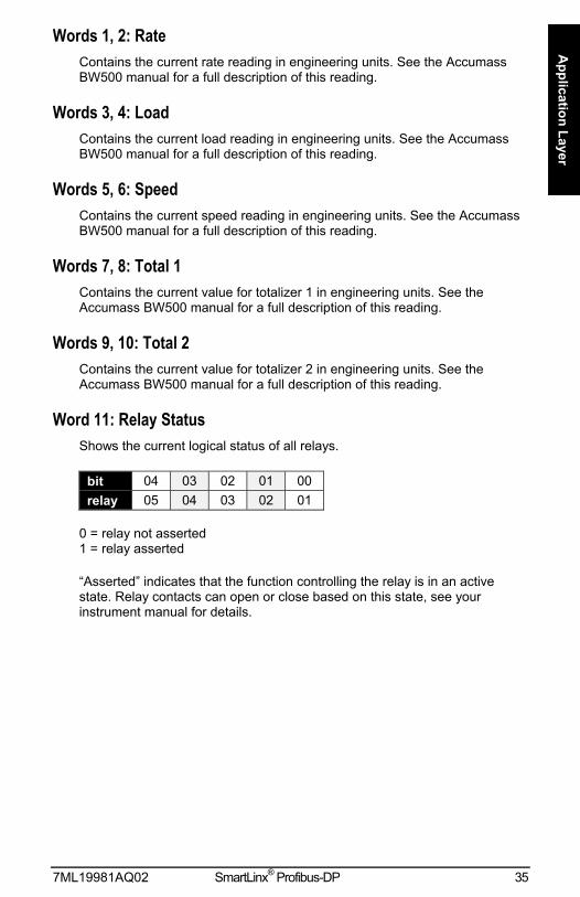
Words 1, 2: RateContains the current rate reading in engineering units. See the AccumassBW500 manual for a full description of this reading.
Words 3, 4: LoadContains the current load reading in engineering units. See the AccumassBW500 manual for a full description of this reading.
Words 5, 6: SpeedContains the current speed reading in engineering units. See the AccumassBW500 manual for a full description of this reading.
Words 7, 8: Total 1Contains the current value for totalizer 1 in engineering units. See theAccumass BW500 manual for a full description of this reading.
Words 9, 10: Total 2Contains the current value for totalizer 2 in engineering units. See theAccumass BW500 manual for a full description of this reading.
Word 11: Relay StatusShows the current logical status of all relays.
bit 04 03 02 01 00relay 05 04 03 02 01
0 = relay not asserted1 = relay asserted
Asserted indicates that the function controlling the relay is in an activestate. Relay contacts can open or close based on this state, see yourinstrument manual for details.

36 SmartLinx® Profibus-DP 7ML19981AQ02
App
licat
ion
Laye
rWord 12: Discrete Input Status
Shows the current logical status of all discrete inputs.
bit 04 03 02 01 00relay 05 04 03 02 01
0 = discrete input open1 = discrete input closed
Word 13: Multispan SelectionShows the currently selected span (1 to 4).
Words 14, 15: PID 1 Setpoint ValueContains the current setpoint value for PID 1 in engineering units. See theAccumass BW500 manual for a full description of this reading.
Words 16, 17: PID 2 Setpoint ValueContains the current setpoint value for PID 2 in engineering units. See theAccumass BW500 manual for a full description of this reading.
Words 18, 19: Batch Setpoint ValueContains the value of P564 Batch Setpoint. See the Accumass BW500manual for a full description of this parameter.
Words 20, 21: Batch Pre-Warn Setpoint ValueContains the value of P567 Batch Pre-Warn Setpoint. See the AccumassBW500 manual for a full description of this parameter.
Words 22 to 24: Parameter Number / Primary Index / SecondaryIndex, SPA
These words contain the last values written to words 0 to 2 of the write area.They confirm that the parameter value has been written. These words arenot updated until the value has been successfully transferred and stored inthe Milltronics SmartLinx instrument.
Words 25, 26: Value, SPAThe value of the specified parameter and index.
Word 27: Decimal Place, SPAThis word specifies the number of decimal places for the value in words25/26.
Positive values indicate that the decimal place shifts to the left.

7ML19981AQ02 SmartLinx® Profibus-DP 37
Application Layer
i.e. A 1 means that all returned values have the decimal place shifted 1space to the left and a returned value of 5,213 is interpreted as 521.3.
Negative values indicate that the decimal place shifts to the right.
i.e. If this word is -1, a returned value of 5,213 is interpreted as 52,130.
Word 28: Format, SPAThis word is always 0.
Word 29: Read / Write Flag, SPAThis word mirrors the read/write word 7.
0 = read1 = write
Word 30: Word OrderThe placement of the most significant word (MSW).
0 = MSW first1 = MSW second

38 SmartLinx® Profibus-DP 7ML19981AQ02
App
licat
ion
Laye
r
Data TypesThe Milltronics SmartLinx instrument parameters take on many values invarious formats, as discussed in the Milltronics SmartLinx instrumentmanual. For the convenience of the programmer, those values are convertedto and from 16-bit integer numbers, since those are easily handled by mostPLCs.
IntegerLevel ProductsInteger parameter values are by far the most common. For example,parameter P920 (Reading) returns a number representing the currentreading (either level or volume, depending on the Milltronics SmartLinxinstrument configuration).
Numeric values may be requested or set in units or percent of span, andmay be specified with a number of decimal places.
Numeric values must be in the range -20,000 to be +20,000 to be valid. If aparameter is requested and its value is more than +20,000, the number32,767 is returned; if it is less than -20,000, the number -32,768 is returned.If this happens, increase the number of decimal places for that parameter.
If a parameter cannot be expressed in terms of percent (e.g. span), or hasno meaningful value, the special number 22,222 is returned. Try requestingthe parameter in units, or refer to the Milltronics SmartLinx instrumentmanual to understand the format and use of the requested parameter.
Mass Dynamics ProductsIntegers used on the Mass Dynamics products can have any valid value. So,the entire range from -32,768 to 32,767 or 0 to 65,535 is available and novalues are used as error conditions.
Bit ValuesBits are packed into registers in groups of 16 bits (1 word). In this manualbits are numbered from 00 to 15, with bit 00 referring to the least significantbit and bit 15 referring to the most significant bit.
15 14 13 12 11 10 09 08 07 06 05 04 03 02 01 00
MSB LSB
7ML19981AQ02 SmartLinx® Profibus-DP 39
Application Layer
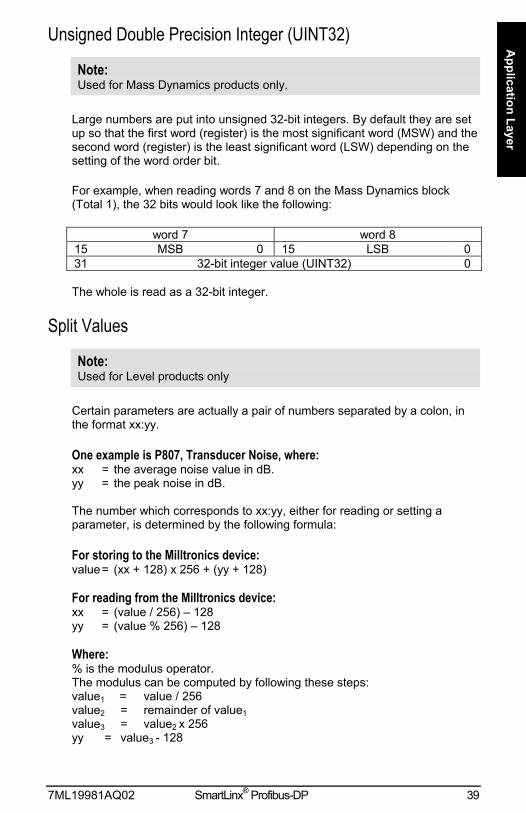
Unsigned Double Precision Integer (UINT32)
Note:Used for Mass Dynamics products only.
Large numbers are put into unsigned 32-bit integers. By default they are setup so that the first word (register) is the most significant word (MSW) and thesecond word (register) is the least significant word (LSW) depending on thesetting of the word order bit.
For example, when reading words 7 and 8 on the Mass Dynamics block(Total 1), the 32 bits would look like the following:
word 7 word 815 MSB 0 15 LSB 031 32-bit integer value (UINT32) 0
The whole is read as a 32-bit integer.
Split Values
Note:Used for Level products only
Certain parameters are actually a pair of numbers separated by a colon, inthe format xx:yy.
One example is P807, Transducer Noise, where:xx = the average noise value in dB.yy = the peak noise in dB.
The number which corresponds to xx:yy, either for reading or setting aparameter, is determined by the following formula:
For storing to the Milltronics device:value= (xx + 128) x 256 + (yy + 128)
For reading from the Milltronics device:xx = (value / 256) 128yy = (value % 256) 128
Where:% is the modulus operator.The modulus can be computed by following these steps:value1 = value / 256value2 = remainder of value1value3 = value2 x 256yy = value3 - 128
40 SmartLinx® Profibus-DP 7ML19981AQ02
App
licat
ion
Laye
rIt may simplify programming to notice:xx = (most significant byte of value) 128yy = (least significant byte of value) 128
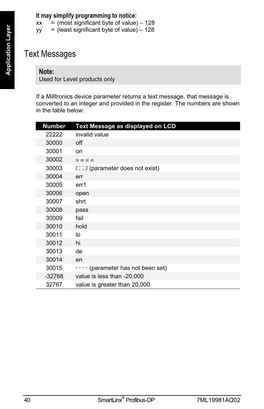
Text Messages
Note:Used for Level products only
If a Milltronics device parameter returns a text message, that message isconverted to an integer and provided in the register. The numbers are shownin the table below:
Number Text Message as displayed on LCD22222 invalid value30000 off30001 on30002 ≡ ≡ ≡ ≡30003 (parameter does not exist)30004 err30005 err130006 open30007 shrt30008 pass30009 fail30010 hold30011 lo30012 hi30013 de30014 en30015 (parameter has not been set)-32768 value is less than -20,00032767 value is greater than 20,000

7ML19981AQ02 SmartLinx® Profibus-DP 41
Application Layer
Relay Function Codes (P111 in Level Products Only)If a Milltronics instrument parameter returns a relay function code, thatmessage is converted to a number and provided in the register. Thenumbers are shown in the table below:
Relay Function Code Number P111off, relay not used 0 0undesignated level alarm 1 1low-low level alarm 2 1 LLlow level alarm 3 1 Lhigh level alarm 4 1 Hhigh-high level alarm 5 1 HHin bounds alarm 6 2in bounds alarm 7 2 B1in bounds alarm 8 2 B2out of bounds alarm 9 3out of bounds alarm 10 3 B1out of bounds alarm 11 3 B2rate of level change alarm 12 4rate of level change alarm 13 4 R1rate of level change alarm 14 4 R2temperature alarm 15 5loss of echo (LOE) alarm 20 6transducer cable fault alarm 16 7pump efficiency alarm 17 8clock failure alarm 18 9time of day alarm 19 10pump failure alarm 21 11totalizer 22 40flow sampler 23 41fixed duty assist 25 50fixed duty backup 26 51alternate duty assist 30 52alternate duty backup 31 53service ratio duty assist 35 54service ratio duty backup 36 55first in first out (FIFO) 40 56time 45 60overflow 50 61aeration 55 62gate 60 63flush valve 65 64communication 66 65pump failure alarm 70 11power failure alarm 71 12unknown function 200
See the manual for the Milltronics SmartLinx instrument for full informationon P111.

42 SmartLinx® Profibus-DP 7ML19981AQ02
Trou
bles
hoot
ing
TroubleshootingGenerally
In all cases, first check that the SmartLinx module has passed its on-goingbuilt-in self test (Milltronics SmartLinx instrument parameter P790). Theresult should be pass.
If fail is indicated, either the module is defective, or the module connectoron the Milltronics SmartLinx instrument is defective.
If err1 is indicated, the Milltronics software doesnt recognize the ID numberof the installed module. Please contact Milltronics or your distributor forinstructions and/or upgraded Milltronics SmartLinx instrument software.
Make sure the Milltronics device is set to a unique address, and does notconflict with any other slave(s) on the bus.
Check the configuration of the scanning master, and make sure it isfunctioning properly.
1. I have configured the Milltronics device in the Master and downloadedit to the processor, but the device is not coming on line.• Check which GSD file you use, and make sure you used the correct one
(see GSD Files on page 16).
• Check the wiring to the card. In particular, check that you have line Aand B connected correctly.
• Verify that you set the correct address on the card. Also, please notethat the card does not see a charge until the power has been cycled.
2. The network was working fine until we connected to the Milltronicsdevice, at which time, other devices dropped out.• Check the termination switch on the Profibus card. The network cable
has to be terminated at both ends of the LAN, but not in between.
• Check your grounding. The Profibus specifications require that alldevices be on the same ground. Improper grounding can cause strangethings to happen.

7ML19981AQ02 SmartLinx® Profibus-DP 43
Troubleshooting
44 SmartLinx® Profibus-DP 7ML19981AQ02
Inde
x
IndexAbout this Manual ............................. 7About this Module ............................. 8Accumass BW 500
connection ...................................... 14Accumass BW500
Operation.................................. 16, 17Address .............................................. 11AiRanger Series
connection ...................................... 12operation ........................................ 16
Alarm and Status ................................ 29Application Layer ................................ 20Audience............................................... 7Batch Prewarn Setpoint ...................... 36Batch Pre-Warn Setpoint Value.......... 39Batch Setpoint .................................... 35Batch Setpoint Value .......................... 39Baud Rate........................................... 11Bit Values ........................................... 41Cable
connector........................................ 12routing ............................................ 10
Command Control, OperationalCommands..................................... 33
Communication Setup ........................ 18Communication Speed ...See Baud RateCompatibility ......................................... 9Compatible Instruments........................ 5Configuration
files ................................................. 18master device ................................. 18
Configuration Status ........................... 37CraneRanger
connection ...................................... 12operation ........................................ 16
Data Access Methods......................... 21Data Map
level products ................................. 25mass dynamics products................ 31
Data Types ......................................... 41Bit Values ....................................... 41integer ............................................ 41Numeric .......................................... 41P111 Values ................................... 44Split Values .................................... 42text messages ................................ 43UINT32 ........................................... 42
Decimal Place............. 26, 27, 30, 32, 40Direct Access...................................... 22Discrete Input Status .......................... 39EnviroRanger ERS 500
connection ................................ 12, 14Operation.................................. 16, 17
Error Conditions.................................. 17Error Status LEDs.............................. 16Flag..................................................... 30Format ........................ 26, 27, 30, 32, 40Freeze ................................................ 34
GSD Files ........................................... 18Index................................................... 30
alarm and status............................. 29MPA................................................ 22point reading................................... 29primary............................................ 20secondary....................................... 21SPA ................................................ 24
Indexed Parameters ........................... 20Installation ............................................ 9Instrument
compatibility...................................... 9Instrument Status ............................... 37Integer................................................. 41InterRanger DPS 300
connection ...................................... 12operation ........................................ 16
LEDs................................................... 16LED's
Error state....................................... 16Level Products
data map ........................................ 25Load.................................................... 38Mark......................See Secondary IndexMass Dynamics
data map ........................................ 31Master Reset ...................................... 20Measurement Point Status ................. 28MPA
overview ................................... 21, 22parameter indexing......................... 22using............................................... 22
Multiple Parameter AccessSee MPA.See MPA
Multispan Selection ...................... 35, 39Network Address ................................ 11Numeric Values .................................. 41Operating Mode.................................. 27Operation............................................ 16Operation LED.................................... 17P999 ................................................... 20Parameter ..................................... 26, 32
writing in block................................ 24Parameter Indexes ............................. 20Parameter Number ................. 26, 30, 39Parameter Number and Secondary
Index .............................................. 30Parameter Secondary Index ............... 26PID 1 Setpoint Value .......................... 39PID 2 Setpoint Value .......................... 39PID Mode............................................ 34PID Setpoints...................................... 35PID Status .......................................... 37Point ................... 30. See Primary IndexPoint Alarm and Status....................... 29Point Reading ..................................... 29Point-on-Priority .................................. 25Primary Index.................... 20, 27, 32, 39

7ML19981AQ02 SmartLinx® Profibus-DP 45
IndexPrint .................................................... 35Print Status ......................................... 37Program Mode.................................... 38Rate .................................................... 38Read
mass dynamics products................ 36Read/Write Flag...................... 27, 32, 40Reading .............................................. 29
level products ................................. 28MPA................................................ 22SPA ................................................ 23
Relay Function Codes ........................ 44Relay Status ....................................... 38Resistor
termination...................................... 12Returned Values................................. 30Run Mode Types ................................ 21Secondary Index............... 21, 27, 32, 39Setpoint Source .................................. 34Setup
communication ............................... 18Single Parameter Access ........ See SPASPA
overview ......................................... 23parameter indexing......................... 24reading ........................................... 23using............................................... 23writing ............................................. 24
Span ................................................... 34Span Status ........................................ 37
Specifications ....................................... 5Speed ................................................. 38Split Values......................................... 42Status ................................................. 16Terminal Block
connector........................................ 12Termination Switch ....................... 11, 12Text Messages ................................... 43Total 1................................................. 38Total 2................................................. 38Totalizer Reset ................................... 35Totalizer Status................................... 37Totalizing Status ................................. 38Troubleshooting.................................. 46UINT32 ............................................... 42Unsigned Double Precision Integer .... 42Using
MPA................................................ 22SPA ................................................ 23
Value ................................ 27, 31, 32, 39Wiring
connector........................................ 12Word Order ................................... 36, 40Write
mass dynamics products................ 31Write Privileges................................... 37Writing ................................................ 24
level products ................................. 25Zero .................................................... 34Zero Status ......................................... 37

*7ml19981aq02*Rev. 2.0