smartengine ready Luminaire Design Guide - Ihr IT … · · 2017-08-03smartengine ready Luminaire...
13
smartengine ready Luminaire Design Guide version 1.0
-
Upload
duongxuyen -
Category
Documents
-
view
216 -
download
0
Transcript of smartengine ready Luminaire Design Guide - Ihr IT … · · 2017-08-03smartengine ready Luminaire...

smartengine ready Luminaire Design Guide version 1.0

smartengine ready Luminaire Design | Compatibility Guide
1
1. Introduction
smartengine promotes fixtures from a group of LED luminaire partners who offer “smartengine Ready” models. These models are provided factory-ready to connect to the smartengine Platform. In many cases, the changes simply consist of removing the driver and adding the smartfixture RJ45 interface SE-SI-1CH or SE-SI-2CH. In certain cases, an integrated smartengine Sensor may be required to be physically incorporated into the fixture. Below is a checklist to ensure a fixture is smartengine ready. Each step includes links for additional detail. Smartengine ’ luminaire applications engineers (contact info on page 1) are available to answer any questions and to verify a smartengine ready design before production begins.
2. Luminaire Approval Checklist
Checkbox: Familiarize Yourself with the smartengine Platform The smartengine Platform is the world’s first integrated power and control platform for commercial solid-state lighting. More detail on the individual components is available on page 3. Checkbox: Verify Electrical Demands The smartengine Platform utilizes individual “channels” to provide power and communication to a fixture. Each channel of an smartengine 3 can provide up to 34W of direct current (DC) power to a luminaire. See page 4 for electrical design recommendations and examples, and then use the “smartengine LED Compatibility Checker” Excel spreadsheet to verify your design. Checkbox: RJ45 Adapter The smartengine Platform provides low voltage DC power through a standard RJ45 connection. Fixture partners can use their preference of a self sourced RJ45 plug or the W-Tec RJ45 adapter. Refer to page [7] for detail on sourcing and installation of the RJ45 plugs. Checkbox: Submit Luminaire Information to smartengine The form on page 8 provides a simple way to get feedback on a fixture design within 48 hours.
Checkbox: Testing and Final Preparation As the final step in the process, a fixture sample is tested at smartengine laboratory and new specification sheets for the smartengine ready model are released.

smartengine ready Luminaire Design | Compatibility Guide
2
3. Familiarize Yourself with the smartengine Platform
Figure 1: smartengine Platform Architecture
smartengine has taken a unique approach by combining a centralized intelligent driver for LED luminaires with integrated communications and control to deliver the world's first integrated power and control platform for commercial solid‐ state lighting. As shown in Figure 1, the smartengine Platform consists of the smartengine, smartsensors, smartgateway, smartmanager and smartswitch, which all work together to power and control a variety of luminaires. All power, control, and sensing is performed over the same low voltage wiring. Each component is described in detail below. smartengine: the smartengine is the core of the smartengine Platform, providing centralized power conversion from high-voltage AC to low‐ voltage DC, communications, processing, and policy control for up to multiple luminaires. smartengine fits inside a 1.5U 19” rack and can drive up to 48 luminaires at 34W per channel. Multiple smartengines can be networked and will automatically discover each other and operate as a single system for larger configurations. smartgateway: the smartgateway profiles the LED luminaire and transfers the low-voltage DC power from the smartengine to the LED luminaire. It communicates this data to the smartengine in the same low-voltage DC wiring through which power is transmitted. The smartgateway provides flexibility for contractors to run standard RJ45 category cabling directly to a luminaire. The smartengine Sensor can easily be installed in the plenum next to a fixture or integrated directly into a fixture before it is shipped from the factory to preserve aesthetics and to simplify installation in the field. See Advanced Smartengine Integration on page [10] for more information.

smartengine ready Luminaire Design | Compatibility Guide
3
smartsensor: This small device equips every luminaire in a building with motion, daylight, and ambient temperature sensing. This unit collects data about light usage, occupancy patterns, environmental conditions, and operating conditions in the building on a per-luminaire basis and reports back to the smartmanager through an integrated gateway. smartmanager: the smartmanager software is embedded in the smartengine. It requires no additional software to be installed and is accessible via any web browser connected to the same network/subnet/VLAN as the smartengine Platform. smartswitch: the smartswitch allows for room or zone scene and on/off and automatic control. It can be easily re-mapped to different lights or groups of lights, and includes embedded sensing capabilities (motion, daylight, ambient temperature) to augment sensor data collection in the system.
4. Verify Electrical Demands
Item Symbol Value
Input Current -Maximum iin, max 700mA
Input Current - Minimum iin, max 150mA
Input Voltage -Maximum Vin, max Vin, max = 53.2 – (iin, * 7.25)
ex:
Vin, max = 50.5 V when iin, = 350mA
Vin, max = 49.7 V when iin, = 450mA
Vin, max = 47.8 V when iin, = 700mA
Input Voltage - Minimum Vin, max 18V
Table 1: Engine 3 Supported Electrical Input for Each LED Chain
Current Supplied Max. Allowable Forward Voltage
150mA 52.4 V
200mA 51.7V
300mA 51V
400mA 50.3V
500mA 49.5V
600mA 48.8V
700mA 48.1V
Forward Voltage Max. Allowable Current
20V 700mA
30V 700mA
40V 700mA
50V 441mA
52V 166mA
Table 2: Examples of Design for smartengine 3

smartengine ready Luminaire Design | Compatibility Guide
4
The smartengine Platform converts high-voltage AC power (120-250VAC or 277VAC) to constant-current DC power that is used directly to power the LED chains within an LED luminaire. This is done through one or more channels. A “channel” is a smartengine concept and is defined as a unique electrical and data linkage running from the smartengine to the smartsensor or smartgateway and then to an LED chain in the luminaire. Each channel is limited in the power it can provide, but the smartengine Platform can provide multiple channels to an individual luminaire containing multiple electrically isolated LED chains in order to support larger power requirements. A single sensor can connect and control one Channel, and an embedded smartgateway can control up to two channels. Each smartengine channel is designed to conform to NEC Class 2 safety standards and to provide the full design power to a fixture installed 100 meters away from the engine.
smartengine recommends that luminaires be designed to minimize channel count, thereby reducing the cost to the end user. On the following pages are examples of compatible and incompatible LED chain designs. Figure 2 shows two LED chain examples that meet the electrical design parameters described in Table 1. Circuit 1 utilizes typical high-brightness LEDs and Circuit 2 utilizes typical mid-brightness LEDs. Circuit 3 in Figure 3 shows a situation that is not compatible with smartengine and a solution to this situation. It should be noted that Circuit 3 could be a single channel on smartengine if each of the two strings wired in parallel require 350mA or less. These designs are provided for reference; a smartengine applications engineer can verify your LED chain design before you commit to a final layout.

smartengine ready Luminaire Design | Compatibility Guide
5
Figure 2: Two Compatible LED Chain Designs

smartengine ready Luminaire Design | Compatibility Guide
6
Figure 3: Example of How to Modify an Incompatible LED Chain

smartengine ready Luminaire Design | Compatibility Guide
7
5. Wiring Options
Wires should be exposed that provide connection to the internal LED chains. To facilitate connection to a smartgateway, wires will be terminated in the field to a smartengine supplied RJ45 connector or two channel integrated gateway. Wire Type:
• For a fixture to be rated for use in air-‐ handling spaces, it is necessary that the wires be rated for installation in open-‐ air return (plenum) ceilings without restriction. Check local codes in the markets that the luminaire is to be sold for plenum installation requirements. The smartgateways and smartsensors are plenum rated.
Wire Length: As shown in Figure 1, a smartengine Ready luminaire is connected to the smartengine Platform via the smartsensor. If not integrated directly into the luminaire, the smartsensor is typically installed in the ceiling adjacent to each luminaire (on the same plane as the luminaire). Hence, it is important that the wiring harness coming out of the luminaire is long enough to allow for flexible installation of the smartgateway in the ceiling in close proximity to the luminaire. As a fixture provider, this means that the length of the pigtail with the attached RJ45 should be at least 3‘ or 1m in length. In certain situations, there may be a requirement for this pigtail length to be longer, and will be reviewed for specific projects on an as needed basis. For lay-‐ in, downlight, and other recessed or surface mounted luminaires: The wire length needs to be long enough such that the connector extends at least 12” (300mm) beyond the luminaire when the wiring is parallel to the longest edge of the luminaire. Figure 4 shows the minimum wire length on two examples: standard 2x2 and 1x4 lay-‐ in luminaires. Note that for the 1x4 example, the desired wire length is at least 36”, such that the connector extends at least 12” beyond the luminaire when the wiring is parallel to the longest (48”) edge.
Figure 4: Wire length specification example on 2x2 and 1x4 lay-in luminaires
For suspended luminaires and other luminaire types that are not ceiling-mounted: The wire length needs to be long enough such that the connector extends at least 12” (300mm) beyond the ceiling height, while taking into account the distance from the ceiling at which the luminaire could be installed. For suspended luminaires, the wire length supplied could vary depending on the length of the suspension hardware specified, but the wire length should always exceed the suspension length by at least 12” to prov ide flexibility for installing the Smartengine Gateway and Sensor on the plane of the canopy. Rather than specifying that the smartsensor be installed in the ceiling overhead, pendant luminaires can allow for internal or surface mounting of a smartsensor (please speak with a Smartengine Systems luminaire engineer for further info).

smartengine ready Luminaire Design | Compatibility Guide
8
Connectorization: For single channel fixtures, fixture manufacturers may purchase the smartfixture RJ45 interface from W-Tec, or source RJ45 connectors from a 3rd party. These interfaces should be attached to the end of the 18 AWG wire at the factory and shipped as part of the completed smartengine Ready Luminaire. For two channel fixtures, purchase the Pigtail-‐ 2-‐ Fixture from smartengine. These adapters should be attached to the end of the 18 AWG wire at the factory and shipped as part of the completed smartengine Ready Luminaire.

smartengine ready Luminaire Design | Compatibility Guide
9
Additional Mechanical & Wiring Considerations: • The negative (and positive) leads on each LED chain must be electrically isolated from any other circuit or component on the luminaire, including the chassis/frame, so that no additional return paths to ground are introduced. The LED chains shown in Figure 2 highlight the electrical isolation required of the negative (and positive) leads. • Should there be any “bundling” or grouping of wires inside of the luminaire (with heatshrink, electrical tape, cable ties, etc.), it is recommended that only the positive (+) and negative (-‐ ) leads from the same LED chain be grouped together to avoid unintentional shorting. • smartengine Ready luminaires no longer have LED chains wired to an onboard driver. Often the driver served as an attachment point and strain relief for the wiring (in addition to providing the main power conversion functionality). With the onboard driver removed, it is often necessary to add additional strain reliefs and/or cable tie mounts to ensure that the wiring does not inadvertently protrude in front of the LEDs, causing unsightly shadowing effects, or become disconnected from the LED board in the course of typical handling and installation. • Luminaires should ship with the hardware necessary to meet seismic requirements of the local codes in the markets that the luminaire is to be sold.
6. Lumen Output
All luminaire samples should include LM79 testing to validate lumen output at the smartengine rated current.
7. smartengine Ready Luminaire Questionnaire
Luminaire:
Luminaire Manufacturer
Luminaire Model
Luminaire Form Factor and Size
Color Temperatures Available
Lumen Output & Power Consumption lm @ Watts DC
Markets Available for Sale (US, Canada, Eur, …)
Certifications (UL/ETL, cUL/cETL, CE, LM79, ...)
Warranty Provided
LEDs:
LED Manufacturer
LED Model
LED Description
Item Symbol Value
Input Current –Maximum iin,max
Forward Voltage vF,max V @ mA
vF,typical V @ mA
vF,min V @ mA
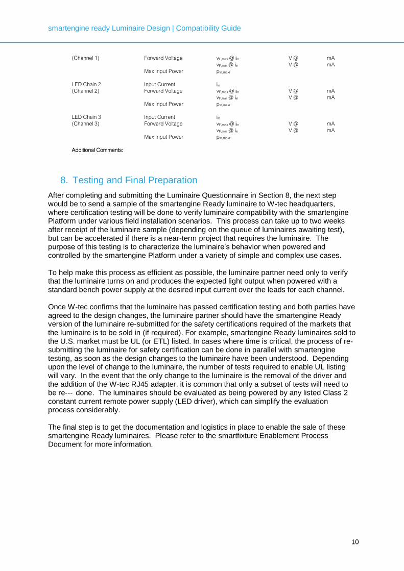
LED Chain(s):
Number of LEDs in Series
Number of Parallel Chains of LEDs in Series
Chain Configuration (series, series-parallel, etc.)
Item Symbol Value
LED Chain 1 Input Current iin
smartengine ready Luminaire Design | Compatibility Guide
10
(Channel 1) Forward Voltage vF,max @ iin V @ mA
vF,min @ iin V @ mA
Max Input Power pin,maxr
LED Chain 2 Input Current iin
(Channel 2) Forward Voltage vF,max @ iin V @ mA
vF,min @ iin V @ mA
Max Input Power pin,maxr
LED Chain 3 Input Current iin
(Channel 3) Forward Voltage vF,max @ iin V @ mA
vF,min @ iin V @ mA
Max Input Power pin,maxr
Additional Comments:
8. Testing and Final Preparation
After completing and submitting the Luminaire Questionnaire in Section 8, the next step would be to send a sample of the smartengine Ready luminaire to W-tec headquarters, where certification testing will be done to verify luminaire compatibility with the smartengine Platform under various field installation scenarios. This process can take up to two weeks after receipt of the luminaire sample (depending on the queue of luminaires awaiting test), but can be accelerated if there is a near-term project that requires the luminaire. The purpose of this testing is to characterize the luminaire’s behavior when powered and controlled by the smartengine Platform under a variety of simple and complex use cases. To help make this process as efficient as possible, the luminaire partner need only to verify that the luminaire turns on and produces the expected light output when powered with a standard bench power supply at the desired input current over the leads for each channel. Once W-tec confirms that the luminaire has passed certification testing and both parties have agreed to the design changes, the luminaire partner should have the smartengine Ready version of the luminaire re-submitted for the safety certifications required of the markets that the luminaire is to be sold in (if required). For example, smartengine Ready luminaires sold to the U.S. market must be UL (or ETL) listed. In cases where time is critical, the process of re‐submitting the luminaire for safety certification can be done in parallel with smartengine testing, as soon as the design changes to the luminaire have been understood. Depending upon the level of change to the luminaire, the number of tests required to enable UL listing will vary. In the event that the only change to the luminaire is the removal of the driver and the addition of the W-tec RJ45 adapter, it is common that only a subset of tests will need to be re-‐ done. The luminaires should be evaluated as being powered by any listed Class 2 constant current remote power supply (LED driver), which can simplify the evaluation process considerably. The final step is to get the documentation and logistics in place to enable the sale of these smartengine Ready luminaires. Please refer to the smartfixture Enablement Process Document for more information.

smartengine ready Luminaire Design | Compatibility Guide
11
W-tec AG
Dornbachstrasse 1a
61352 Bad Homburg
Germany
www.wtec.ag
Contacts
Aras Sarafi
Head of Department smartengine
+49-176-199-59-816
AJ Dinger
Business Development and Strategic Initiatives
+1-415-940-4110
Copyright © W-tec AG

smartengine ready Luminaire Design Guide version 1.0