Smart UPS 1000RM3U%2C 1400RM3U
31
990-1021, Revision 1 5/00 User’s Manual English APC Smart-UPS 1400 VA 3U Rack and Stack Uninterruptible Power Supply 120 Vac
-
Upload
alvesfabiano -
Category
Documents
-
view
235 -
download
0
Transcript of Smart UPS 1000RM3U%2C 1400RM3U
990-1021, Revision 1 5/00
User’s Manual English
APC Smart-UPS
1400 VA 3U Rack and StackUninterruptible Power Supply
120 Vac

990-1021, Revision 1 5/00
Entire contents copyright © 2000 by American Power Conversion Corporation. All rightsreserved. Reproduction in whole or in part without permission is prohibited.APC, Smart-UPS, and PowerChute are registered trademarks of American PowerConversion Corporation. All other trademarks are the property of their respective owners.

990-1021, Revision 1 5/00
Table of ContentsChapter 1: Safety Information..............................................................1
Conventions Used in this Manual..........................................................1Handling Safety .....................................................................................1Electrical Safety.....................................................................................2Deenergizing Safety ..............................................................................2Battery Safety ........................................................................................2Replacement and Recycling of Batteries ...............................................2
Chapter 2: Basics....................................................................................3About Your UPS....................................................................................3Limited Warranty ..................................................................................3How To Contact APC............................................................................4
North America ...................................................................................4Latin America ....................................................................................4
Chapter 3: Installing Your Smart-UPS................................................5
Unpacking..............................................................................................5Inspection...........................................................................................5Contents .............................................................................................5Placement...........................................................................................5
How To Install the Smart-UPS..............................................................5Place The UPS Where It Will Be Used..............................................6Connect the Batteries and Attach the Front Bezel .............................9Connect Power and Equipment to the UPS .....................................10Turn on the UPS...............................................................................11Install PowerChute Software (Optional)..........................................11
Chapter 4: Operating the Smart-UPS................................................13Indicators and Controls on the Smart-UPS..........................................13
Smart-UPS Front Panel....................................................................13Smart-UPS Rear Panel .....................................................................16
On-Battery Operation ..........................................................................17How To Determine On-Battery Run Time ..........................................18User Configuration Items ....................................................................19
Chapter 5: Maintenance and Troubleshooting..................................21Storage.................................................................................................21
Storage Conditions...........................................................................21Extended Storage .............................................................................21
Replacing the Battery ..........................................................................21Battery Replacement Procedure.......................................................21
Troubleshooting...................................................................................23

990-1021, Revision 1 5/00
Service .................................................................................................24
Appendix A: Specifications .................................................................25Regulatory Agency Approvals ............................................................26
Radio Frequency Interference..........................................................26
Appendix B: Transporting Your Smart-UPS....................................27

1
CHAPTER 1: SAFETY INFORMATIONThis Safety Guide contains important instructions that should be followed during the installationand maintenance of the APC equipment and batteries. It is intended for APC customers whosetup, install, relocate, or maintain APC equipment.
Conventions Used in this ManualThis section defines the symbols used throughout this manual. Carefully read all informationboxes and abide by the instructions.
The WARNING sign denotes a serious hazard. It calls attention to aprocedure, practice, condition, or the like, which, if not correctlyperformed or adhered to, could result in injury to personnel.
The CAUTION sign denotes a hazard. It calls attention to an operatingprocedure, practice, or the like, which, if not correctly performed oradhered to, could result in damage to or destruction of all or part of theproduct.
The NOTE sign denotes important information. It calls attention to a procedure,practice, condition, or the like, which is essential to highlight.
Handling Safety• Be careful. Do not lift heavy loads without assistance.
<18 kg (<40 lb)
18 32 kg (40 – 70 lb)
32 – 55 kg (70 – 120 lb)
>55 kg (>120 lb)• Equipment with casters is built to move on a smooth surface without any obstacles.
• Do not use a ramp inclined at more than 10°.
• This equipment is intended for installation in a temperature-controlled indoor area (seeAppendix A: Specifications, page 25, for exact temperature range), free of conductivecontaminants.

2
Electrical Safety• To reduce the risk of fire, connect only to a circuit provided with a 20 Amp maximum branch
circuit overcurrent protection in accordance with the National Electrical Code ANSI/NFPA.
• Do not work alone under hazardous conditions.
• Check that the power cord(s), plug(s), and sockets are in good condition.
• Do not block the air vents on the front and rear panels of the UPS.
Deenergizing Safety• If the equipment has an internal energy source (the battery), the output may be energized when
the unit is not connected to an AC power outlet.
• To deenergize pluggable equipment: first press the Off button for more than one second toswitch the equipment off. Next disconnect the equipment from the AC power outlet. Finally,disconnect the battery.
• Pluggable equipment includes a protective earth conductor which carries the leakage currentfrom the load devices (computer equipment). Total leakage current must not exceed 3.5 mA.
• Use of this equipment in life support applications where failure of this equipment canreasonably be expected to cause the failure of the life support equipment or to significantlyeffect its safety or effectiveness is not recommended.
Battery Safety• This equipment contains potentially hazardous voltages. Do not attempt to disassemble the unit.
The only exception is for equipment containing batteries. Battery replacement using theprocedures below is permissible. Except for the battery, the unit contains no user serviceableparts. Repairs are performed only by factory trained service personnel.
• Do not dispose of batteries in a fire. The batteries may explode.
• Do not open or mutilate batteries. They contain an electrolyte which is toxic and harmful to theskin and eyes.
• To avoid personal injury due to energy hazard, remove wrist watches and jewelry such as ringswhen replacing the batteries. Use tools with insulated handles.
• Replace batteries with the same number and type of batteries as originally installed in theequipment.
Replacement and Recycling of BatteriesSee your dealer or Replacing the Battery, page 21, for information on replacement battery kits andbattery recycling.
3
CHAPTER 2: BASICS
About Your UPSThis APC Uninterruptible Power Supply (UPS) is designed to prevent blackouts, brownouts, sagsand surges from reaching your computer and other valuable electronic equipment. This UPS alsofilters out small utility line fluctuations and isolates your equipment from large disturbances byinternally disconnecting from the utility line, while supplying power from its internal batteriesuntil the utility line returns to safe levels.
The UPS has a “rack and stack” design that provides two mounting options. The UPS can bemounted in a 19-inch equipment rack or stacked with other equipment. Hardware is provided foreither option.
Limited WarrantyAmerican Power Conversion (APC) warrants its products to be free from defects in materials andworkmanship for a period of two years from the date of purchase. Its obligation under thiswarranty is limited to repairing or replacing, at its own sole option, any such defective products.To obtain service under warranty you must obtain a Returned Material Authorization (RMA)number from customer support (see Service, page 24). Products must be returned withtransportation charges prepaid and must be accompanied by a brief description of the problemencountered and proof of date and place of purchase. This warranty does not apply to equipmentwhich has been damaged by accident, negligence, or misapplication or has been altered ormodified in any way. This warranty applies only to the original purchaser who must haveproperly registered the product within 10 days of purchase.
EXCEPT AS PROVIDED HEREIN, AMERICAN POWER CONVERSION MAKES NOWARRANTIES, EXPRESSED OR IMPLIED, INCLUDING WARRANTIES OFMERCHANTABILITY AND FITNESS FOR A PARTICULAR PURPOSE. Some states do notpermit limitation or exclusion of implied warranties; therefore, the aforesaid limitation(s) orexclusion(s) may not apply to the purchaser.
EXCEPT AS PROVIDED ABOVE, IN NO EVENT WILL APC BE LIABLE FOR DIRECT,INDIRECT, SPECIAL, INCIDENTAL, OR CONSEQUENTIAL DAMAGES ARISING OUT OFTHE USE OF THIS PRODUCT, EVEN IF ADVISED OF THE POSSIBILITY OF SUCHDAMAGE. Specifically, APC is not liable for any costs, such as lost profits or revenue, loss ofequipment, loss of use of equipment, loss of software, loss of data, costs of substitutes, claims bythird parties, or otherwise.
4
How To Contact APCInternet http://www.apcc.com/contact
North AmericaPhone 1.800.800.4272Fax 1.401.788.2743
Latin AmericaArgentina 0800.9.APCC (0800.9.2722)Brazil 0800.12.72.21Colombia 980.15.39.47Mexico 95.800.804.4283Uruguay 000.413.598.2139Venezuela 8001.2856Email [email protected]
If you ordered a Smart-UPS SU1400RMXL3UX171 unit, please refer to the redaddendum sheet (part number 990-1023) for contact information.
5
CHAPTER 3: INSTALLING YOUR SMART-UPS
UnpackingAPC has taken care to design robust packaging for your product. However, accidents and damagemay occur during shipment.
InspectionInspect the UPS upon receipt. Notify the carrier and dealer if there is damage. The packaging isrecyclable; save it for reuse or dispose of it properly.
ContentsThe shipping package contains the UPS, its front panel bezel (packaged separately), mountingrails, mounting cleats, hardware packet (necessary for rack mounting the UPS), software, twoserial cables, one RJ-45 network cable, and product documentation.
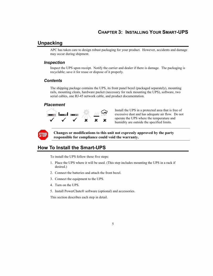
Placement
S m a r t - U P SS m a r t - U P S
S m a r t - U P S
Install the UPS in a protected area that is free ofexcessive dust and has adequate air flow. Do notoperate the UPS where the temperature andhumidity are outside the specified limits.
Changes or modifications to this unit not expressly approved by the partyresponsible for compliance could void the warranty.
How To Install the Smart-UPSTo install the UPS follow these five steps:
1. Place the UPS where it will be used. (This step includes mounting the UPS in a rack ifdesired.)
2. Connect the batteries and attach the front bezel.
3. Connect the equipment to the UPS.
4. Turn on the UPS.
5. Install PowerChute® software (optional) and accessories.
This section describes each step in detail.

6
Place The UPS Where It Will Be Used
Select a location with adequate air flow that is free from excessive dust. Ensurethat the air vents on the front and rear of the UPS are not blocked. Allow at leastone inch of space on both sides.
The UPS requires two people to install due to its weight.To lighten the UPS, you may remove the batteries while you position the UPS ormount it in the rack. Refer to Replacing the Battery, page 21, for instructions on howto remove the batteries.
• UPSs are heavy. Select a location sturdy enough to handle the weight. For rack mounting,install the UPS at or near the bottom of the rack.
• Do not operate the UPS where temperature or humidity are outside the limits listed in AppendixA: Specifications, page 25.
To Stack the Units1. Unpack the four (4) mounting feet shipped in the literature kit.
0
|
B a t t e r yP a c k
2. Turn the UPS on its side so the bottom surface is accessible.
3. Locate the indentations on the bottom of the UPS that mark the feetposition (indicated by arrows in the figure to the left).
4. Peel away the protective film on the back of the feet and press hard toaffix the feet to the UPS.
5. Turn the unit rightside up and place it either on the floor or on anoptional battery pack (shown). The battery pack cover hasindentations for feet on the bottom of either a UPS or another batterypack.
6. Skip to Connect the Batteries and Attach the Front Bezel, page 9, tocomplete the installation.
• Do not step on the UPS. The UPS chassis is not designed to supportadditional weight.
• If you are stacking the UPS with an external battery pack, position the UPSon top of the 2U battery pack. The top of the battery pack has indentationsfor proper placement of the feet on the bottom of the UPS.
7
To Mount the UPS in a Rack
The UPS comes with standard 19-inch (46.5 cm) rack mount brackets (in the literature kit) andmounting rails and cleats. There are three steps to install the UPS in a rack. This sectiondescribes each in detail.
1. Install the mounting rails in the rack (required for four-post racks only).
2. Attach the mounting hardware to the UPS.
3. Load the UPS into the rack and fasten the mounting brackets.
Install the Mounting Rails in the Rack
The mounting rails are designed to fit a four-post rack. The rack can have any of thecommon types of equipment mounting holes (square, round-threaded, or round-non-threaded). All necessary hardware is provided.
If you are using a two-post rack, use only the mounting brackets to mount the UPS.Position the mounting brackets in the mid-point position.
9
91
1
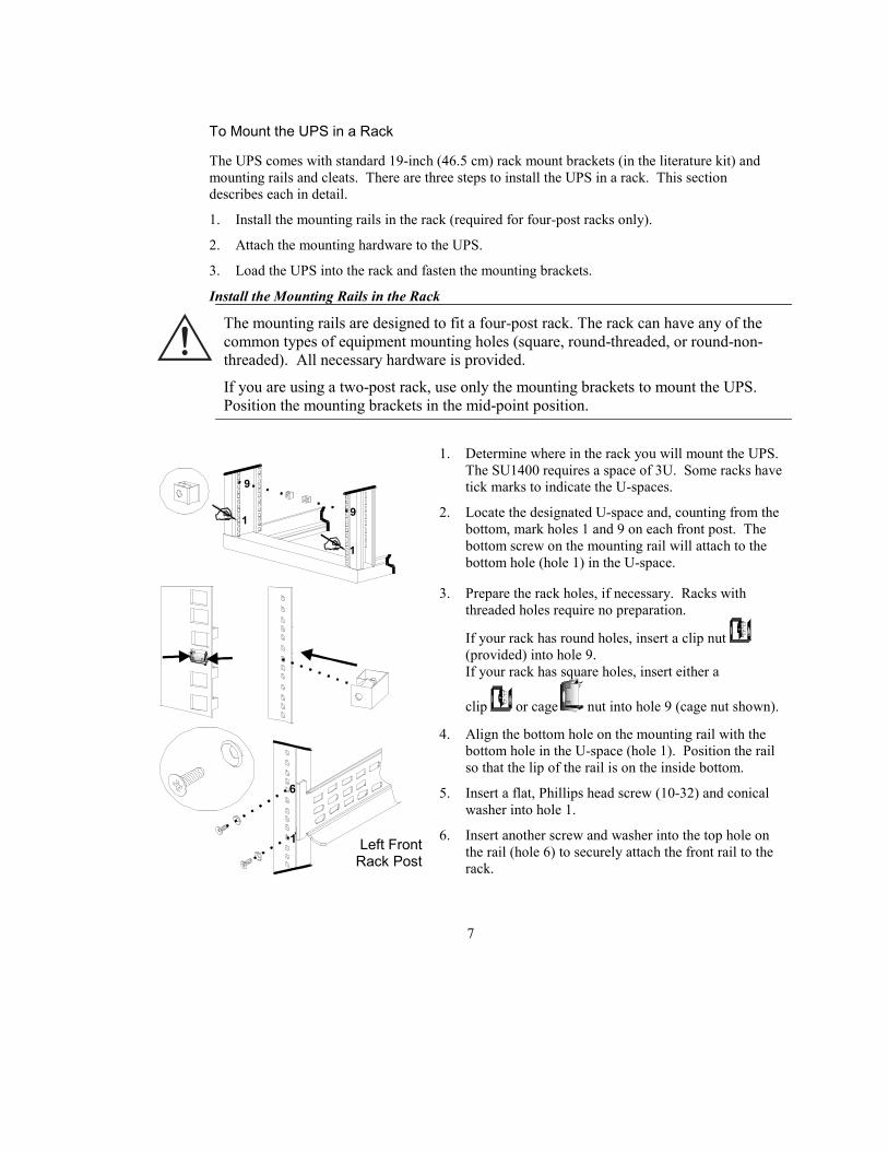
1. Determine where in the rack you will mount the UPS.The SU1400 requires a space of 3U. Some racks havetick marks to indicate the U-spaces.
2. Locate the designated U-space and, counting from thebottom, mark holes 1 and 9 on each front post. Thebottom screw on the mounting rail will attach to thebottom hole (hole 1) in the U-space.
3. Prepare the rack holes, if necessary. Racks withthreaded holes require no preparation.
If your rack has round holes, insert a clip nut (provided) into hole 9.If your rack has square holes, insert either a
clip or cage nut into hole 9 (cage nut shown).
1
6
4. Align the bottom hole on the mounting rail with thebottom hole in the U-space (hole 1). Position the railso that the lip of the rail is on the inside bottom.
5. Insert a flat, Phillips head screw (10-32) and conicalwasher into hole 1.
6. Insert another screw and washer into the top hole onthe rail (hole 6) to securely attach the front rail to therack.
Left FrontRack Post
8
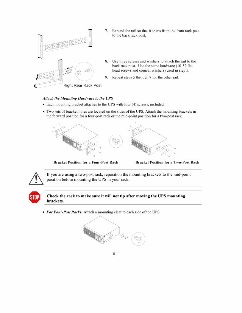
7. Expand the rail so that it spans from the front rack postto the back rack post.
8. Use three screws and washers to attach the rail to theback rack post. Use the same hardware (10-32 flathead screws and conical washers) used in step 5.
9. Repeat steps 5 through 8 for the other rail.
Attach the Mounting Hardware to the UPS• Each mounting bracket attaches to the UPS with four (4) screws, included.
• Two sets of bracket holes are located on the sides of the UPS. Attach the mounting brackets inthe forward position for a four-post rack or the mid-point position for a two-post rack.
Bracket Position for a Four-Post Rack Bracket Position for a Two-Post Rack
If you are using a two-post rack, reposition the mounting brackets to the mid-pointposition before mounting the UPS in your rack.
Check the rack to make sure it will not tip after moving the UPS mountingbrackets.
• For Four-Post Racks: Attach a mounting cleat to each side of the UPS.
Right Rear Rack Post
9
Load the UPS into the Rack
Due to the weight of the UPS, two people are required to install it in the rack.
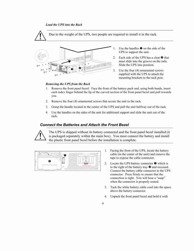
1. Use the handles � on the side of theUPS to support the unit.
2. Each side of the UPS has a cleat � thatmust slide into the groove on the rails.Slide the UPS into position.
3. Use the four (4) ornamental screwssupplied with the UPS to attach themounting brackets to the rack post.
Removing the UPS from the Rack1. Remove the front panel bezel: Face the front of the battery pack and, using both hands, insert
each index finger behind the lip of the curved section of the front panel bezel and pull towardsyou.
2. Remove the four (4) ornamental screws that secure the unit to the rack.
3. Grasp the handle located in the center of the UPS and pull the unit halfway out of the rack.
4. Use the handles on the sides of the unit for additional support and slide the unit out of therack.
Connect the Batteries and Attach the Front Bezel
The UPS is shipped without its battery connected and the front panel bezel installed (itis packaged separately within the main box). You must connect the battery and installthe plastic front panel bezel before the installation is complete.
0
|
1. Facing the front of the UPS, locate the batterycable (in the center of the unit) and remove thetape to expose the cable connector.
2. Locate the UPS battery connector � which isto the right of the battery tray � and recessed.Connect the battery cable connector to the UPSconnector. Press firmly to ensure that theconnection is tight. You will hear a “snap”when the connector is properly seated.
3. Tuck the white battery cable cord into the spaceabove the battery connector.
4. Unpack the front panel bezel and hold it with
�
�
�
�

10
the cutout section on the right. Align the tabson the side of the bezel with the slots on thefront of the UPS and firmly snap it into place.
To connect an optional external battery pack(s) to the UPS, refer to the 2U BatteryPack User’s Manual for instructions. The SU1400 can support a maximum of ten (10)external battery packs.
Connect Power and Equipment to the UPS
Use the cable provided with your UPS to connect to the Computer Interface Port.DO NOT use a standard serial interface cable since it is incompatible with theUPS connector.
Refer to the Software Installation Instruction Sheet, included with the UPS, todetermine whether your application requires using the plug and play (PnP)adapter. Do not use the adapter unless it is necessary.
• Plug the UPS power cord into an appropriate power source.
• Connect equipment to the UPS.
• Turn on all connected equipment (the equipment will not be powered until the UPS is turnedon).
• Add any optional accessories. See the literature accompanying the accessory for details.
• Connect ground leads to the TVSS screw. The transient voltage surge suppression (TVSS)screw provides grounding through the UPS’s power cord ground conductor. See Smart-UPSRear Panel, page 16, for the location of the screw. To make the connection, loosen the screwand connect the surge suppression device’s ground lead. Tighten the screw to secure the lead.
• Check the site wiring fault indicator (located on the rear panel, see Smart-UPS Rear Panel,page 16). It lights up if the UPS is plugged into an improperly wired AC power outlet. Wiringfaults detected include missing ground, hot-neutral polarity reversal, and overloaded neutralcircuit.
If the UPS indicates a site wiring fault, get a qualified electrician to correct thebuilding wiring.
11
Turn on the UPS
Make sure the battery is connected before turning on the UPS!
• Press the UPS’s on |
T E S T button, located on the front panel, to power-up your UPS. This willpower-up connected equipment.
The UPS charges its battery whenever it is connected to utility power. The batterycharges fully during the first four hours of normal operation. Do not expect full runtime during this initial charge period.
• The unit performs a self-test automatically when turned on, and every two weeks thereafter (bydefault). Refer to User Configuration Items, page 19 for details on changing the interval.
Install PowerChute Software (Optional)For additional computer system security, install PowerChute UPS monitoring software. Itprovides automatic unattended shutdown capabilities on most major network operating systems.See the Software Installation Instruction Sheet included with the UPS, for details.
This UPS is equipped with an accessory slot. See the APC website (apcc.com) foravailable accessories.If a standard accessory (such as an SNMP card) is installed on this UPS, follow theinstallation instructions included with the accessory.

12

13
CHAPTER 4: OPERATING THE SMART-UPS
Indicators and Controls on the Smart-UPSThe Smart-UPS has the power control and operating indicators located on the front panel. The rearpanel has the input and output connectors.
Smart-UPS Front Panel
0
|
Switch On – Switch Off|
T E S T To turn the UPS on: With the UPS plugged in, press and release the large, upper button labeled“l TEST” to supply power to the connected equipment. The equipment is immediately poweredwhile the UPS performs a self-test.
0 To turn the UPS off: Press and release the small, lower button labeled “0” to turn off power to theconnected equipment. It may be convenient to use the UPS as a master on/off switch for theconnected equipment.
Whenever the UPS is plugged in and utility voltage is present, the charger maintainsbattery charge.
On-line IndicatorThe on-line indicator illuminates when the UPS is supplying utility power to the connectedequipment.
Load Bar Graph85%67%50%33%17%
The 5-LED display on the left of the front panel represents the power drawn from the UPS as apercentage of total capacity. For example, if three LEDs are lit, the load (connected equipment)is drawing between 50% and 67% of the UPS’s capacity. If all five LEDs light, thoroughly testyour complete system to make sure that the UPS will not become overloaded. In the graphic tothe left, the battery capacity threshold is listed next to the LED (these are not shown on the actualUPS).

14
On Battery
During on-battery operation, the on-battery LED illuminates and the UPS sounds an audible alarmconsisting of four beeps every 30 seconds. The alarm stops when the UPS returns to on-lineoperation. Refer to On-Battery Operation, page 17, for details.
Battery Charge Bar Graph1 0 0 % 8 0 % 6 0 % 4 0 % 2 0 %
The 5-LED display on the right of the front panel shows the present charge of the UPS’s batteryas a percentage of the battery’s capacity. When all five LEDs are lit, the battery is fully charged.The LEDs extinguish, from top to bottom, as the battery capacity diminishes. The batterycapacity threshold is shown in the figure to the left (it is not listed on the front panel display).
As a low battery warning, any LEDs illuminated (for the given capacity) will flash. The lowbattery warning setting can be changed from the rear panel (see Low Battery Warning Level,page 17) or through the PowerChute software.
OverloadWhen the UPS is overloaded (that is, when the connected equipment exceeds the maximumspecified in the “maximum load,” section in Appendix A: Specifications, page 25), the overloadLED comes on and the UPS emits a sustained tone. The alarm remains on until the overload isremoved. The UPS continues to supply power as long as it is on line and the breaker does not trip,but it will not provide power from batteries in the event of a utility voltage interruption.Disconnect nonessential equipment from the UPS to eliminate the overload. If a continuousoverload occurs while the UPS is on battery, the UPS will turn off its output in order to protectitself from possible damage.
Self-TestThe UPS performs a self-test automatically when turned on, and every two weeks thereafter (bydefault). Refer to User Configuration Items, page 19 for details on changing the interval.Automatic self-test eases maintenance requirements by eliminating the need for periodic manualself-tests. During the self-test, the UPS briefly operates the connected equipment on-battery. Ifthe UPS passes the self-test, it returns to on-line operation.
If the UPS fails the self-test it immediately returns to on-line operation and lights the replacebattery LED. The connected equipment is not affected by a failed test. Recharge the battery for24 hours and perform another self-test. If it fails, the battery must be replaced. See Replacing theBattery, page 21, for details.
How to Manually Initiate a Self-Test
Press and hold the on |
T E S T button (on the front panel) for a few seconds before the self-test willbegin.
Replace Battery
If the battery fails a self-test, the UPS emits short beeps for one minute and the replace batteryLED illuminates. (If the LED flashes, the battery is disconnected.) The UPS repeats the alarmevery five hours. Perform the self-test procedure after the battery has charged for 24 hours toconfirm the replace battery condition. The alarm will stop if the battery passes the self-test.
15
Voltage TrimThe voltage trim LED comes on to indicate that the UPS is compensating for a high utilityvoltage.
Voltage BoostThe voltage boost LED comes on to indicate that the UPS is compensating for a low utilityvoltage.
Low BatteryWhen the UPS is operating on-battery and the energy reserve of the battery runs low, the UPSbeeps continuously (by default) until the UPS shuts down from battery exhaustion or returns to on-line operation. The low battery warning interval can be changed through software.
Cold StartWhen the UPS is off and there is no utility power, use the cold start feature to apply power to theconnected equipment from the UPS’s battery. Cold start is not a normal condition.
• Press and hold the on |
T E S T button until the UPS beeps.• Release the on button during the beep and the connected equipment is powered.
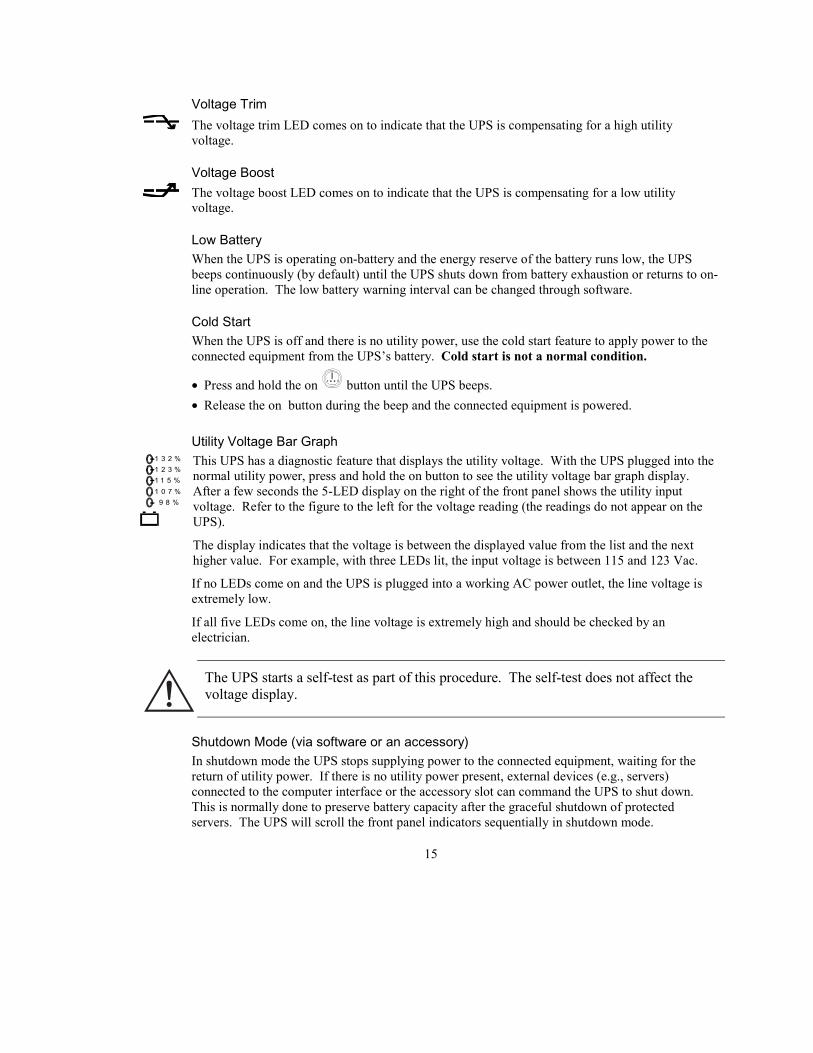
Utility Voltage Bar Graph1 3 2 %1 2 3 %1 1 5 %1 0 7 % 9 8 %
This UPS has a diagnostic feature that displays the utility voltage. With the UPS plugged into thenormal utility power, press and hold the on button to see the utility voltage bar graph display.After a few seconds the 5-LED display on the right of the front panel shows the utility inputvoltage. Refer to the figure to the left for the voltage reading (the readings do not appear on theUPS).
The display indicates that the voltage is between the displayed value from the list and the nexthigher value. For example, with three LEDs lit, the input voltage is between 115 and 123 Vac.
If no LEDs come on and the UPS is plugged into a working AC power outlet, the line voltage isextremely low.
If all five LEDs come on, the line voltage is extremely high and should be checked by anelectrician.
The UPS starts a self-test as part of this procedure. The self-test does not affect thevoltage display.
Shutdown Mode (via software or an accessory)In shutdown mode the UPS stops supplying power to the connected equipment, waiting for thereturn of utility power. If there is no utility power present, external devices (e.g., servers)connected to the computer interface or the accessory slot can command the UPS to shut down.This is normally done to preserve battery capacity after the graceful shutdown of protectedservers. The UPS will scroll the front panel indicators sequentially in shutdown mode.

16
Smart-UPS Rear Panel
M AD E I N U S A (W ES T K IN GS TON , R I )
S U 1400R MX L3U
X X01234 56789
®
Computer Interface PortPower management software and interface kits can be used with this UPS. Use only interface kitssupplied or approved by APC. If used, connect the interface cable to the 9-pin computer inter-face port on the back panel of the UPS. Secure the connector’s screws to complete the connection.
TVSS Screw
The UPS features a transient voltage surge-suppression (TVSS) screw for connecting the groundlead on surge suppression devices such as telephone and network line protectors. Refer toConnect Power and Equipment to the UPS, page 10, for information.
Voltage Sensitivity
The UPS detects line voltage distortions such as spikes, notches, dips, and swells, as well asdistortions caused by operation with inexpensive fuel-powered generators. By default, the UPSreacts to distortions by transferring to on-battery operation to protect the connected equipment.Where power quality is poor, the UPS may frequently transfer to on-battery operation. If theconnected equipment can operate normally under such conditions, battery capacity and service lifemay be conserved by reducing the sensitivity of the UPS.
To reduce UPS sensitivity, press the Sensitivity button on the rear panel. Use a pointed objectsuch as a pen to press the button. Press it once to set the UPS’s sensitivity to reduced. Press itagain to set the sensitivity to low. Press the button a third time to reset normal sensitivity. TheSensitivity can also be changed through software.
normal
reduced
low
When the UPS is set to normal sensitivity, the LED is brightly lit.When it is set to reduced sensitivity, the LED is dimly lit.When it is set to low sensitivity, the LED is off.
17
Battery Pack ConnectorUse the battery pack connector to connect optional external battery pack(s). The SU1400RMXLsupports up to ten (10) external battery packs.
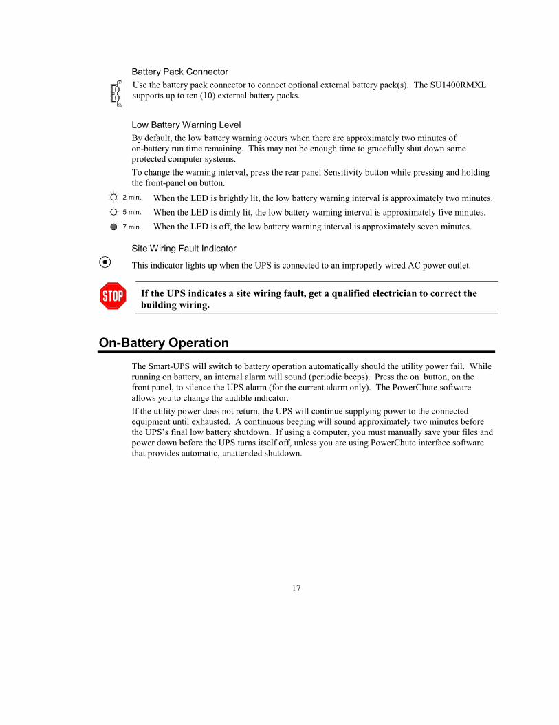
Low Battery Warning LevelBy default, the low battery warning occurs when there are approximately two minutes ofon-battery run time remaining. This may not be enough time to gracefully shut down someprotected computer systems.To change the warning interval, press the rear panel Sensitivity button while pressing and holdingthe front-panel on button.
2 min.
5 min.
7 min.
When the LED is brightly lit, the low battery warning interval is approximately two minutes.When the LED is dimly lit, the low battery warning interval is approximately five minutes.When the LED is off, the low battery warning interval is approximately seven minutes.
Site Wiring Fault Indicator
This indicator lights up when the UPS is connected to an improperly wired AC power outlet.
If the UPS indicates a site wiring fault, get a qualified electrician to correct thebuilding wiring.
On-Battery OperationThe Smart-UPS will switch to battery operation automatically should the utility power fail. Whilerunning on battery, an internal alarm will sound (periodic beeps). Press the on button, on thefront panel, to silence the UPS alarm (for the current alarm only). The PowerChute softwareallows you to change the audible indicator.If the utility power does not return, the UPS will continue supplying power to the connectedequipment until exhausted. A continuous beeping will sound approximately two minutes beforethe UPS’s final low battery shutdown. If using a computer, you must manually save your files andpower down before the UPS turns itself off, unless you are using PowerChute interface softwarethat provides automatic, unattended shutdown.

18
How To Determine On-Battery Run Time
UPS battery life differs based on usage and environment. It is recommended that thebattery/batteries be changed once every three years.
On-Battery Run Time (Minutes)
Load (VA) Load (watts) SU1400
100 60 133
200 122 91
300 185 67
400 249 50
500 315 39
600 382 31
700 450 24
800 522 19
900 595 16
1000 670 13
1200 809 9
1330 900 7
1400 1050 6
Run Time (Minutes) with External Battery Packs (SU24RMXLBP2U)
# of battery packs:Load (VA)
1 2 3 4 5 6 7 8 9 10
700 70 130 210 280 350 420 490 560 640 720
1200 32 65 100 150 190 230 270 310 350 400
1400 23 47 70 100 140 170 200 240 270 300

19
User Configuration ItemsNote: Setting these items requires optional software or hardware.
Function FactoryDefault
User SelectableChoices
Description
Automatic Self-Test
Every 14days(336 hours)
Every 7 days (168hours), On StartupOnly, No Self-Test
Sets the interval at which the UPS willexecute a self-test.
UPS ID UPS_IDEN Up to eight charactersto define the UPS.
Use this field to uniquely identify the UPSfor network management purposes.
Date of LastBattery
ManufactureDate
Date of BatteryReplacement
Reset this date on battery replacement.
MinimumCapacity BeforeReturn fromShutdown
0 percent 15, 50, 90 percent The UPS will charge its batteries to thespecified percentage before return from ashutdown.
Sensitivity Normal Reduced, Low Set lower than normal sensitivity to avoidlowered battery capacity and service life insituations where the load can tolerate minorpower disturbances.
Duration of LowBattery Warning
2 minutes 5, 7, 10 minutes Sets the time before shutdown at which theUPS issues a low battery warning. Sethigher than the default only if the OS needsthe time for graceful shutdown.
Alarm DelayAfter Line Fail
5 seconddelay
30 second delay, AtLow BatteryCondition, No Alarm
To avoid alarms for minor power glitches,set the alarm delay.
Shutdown Delay 20 seconds 0, 80, 300, 600seconds
Sets the interval between when the UPSreceives a shutdown command and whenshutdown occurs.
SynchronizedTurn-on Delay
0 seconds 60, 180, 300 seconds To avoid branch circuit overload, the UPSwill wait the specified time after the returnof utility power before turn-on.
High TransferPoint
132 Vac 138, 135, 129 Vac To avoid unnecessary battery usage, set theHigh Transfer Point higher if the utilityvoltage is chronically high and the load isknown to work well under this condition.
Low TransferPoint
103 Vac 97, 100, 106 Vac Set the Low Transfer Point lower if theutility voltage is chronically low and theload can tolerate this condition.

20

21
CHAPTER 5: MAINTENANCE AND TROUBLESHOOTING
Storage
Storage ConditionsStore the UPS covered and flat (rack mount orientation) in a cool, dry location, with its batteryfully charged. Disconnect any cables connected to the computer interface port to avoidunnecessarily draining the battery.
Extended StorageAt -15 to +30 °C (+5 to +86 °F), charge the UPS’s battery every six months.At +30 to +45 °C (+86 to +113 °F), charge the UPS’s battery every three months.
Replacing the BatteryThis UPS has an easy to replace hot-swappable battery tray. Battery replacement is a safeprocedure, isolated from electrical hazards. You may leave the UPS and the protected equipmenton for the following procedure. See your dealer or APC (refer to How To Contact APC, page 4)for information on replacement battery cartridges.
Unit Replacement Shape
UPS SU1400RMXL3U RBC25
Optional external battery pack SU24RMXLBP2U RBC26
The SU1400RMXL and the optional, external battery pack use different replacementbattery cartridges. The battery cartridges are not interchangeable.
Battery Replacement Procedure
Please read Chapter 1: Safety Information, page 1, before replacing the battery. Oncethe battery is disconnected, the loads are not protected from power outages.
1. The battery is accessible from the front of the UPS.2. Be careful removing the battery—it is heavy.3. This procedure requires a Phillips head screwdriver.
22
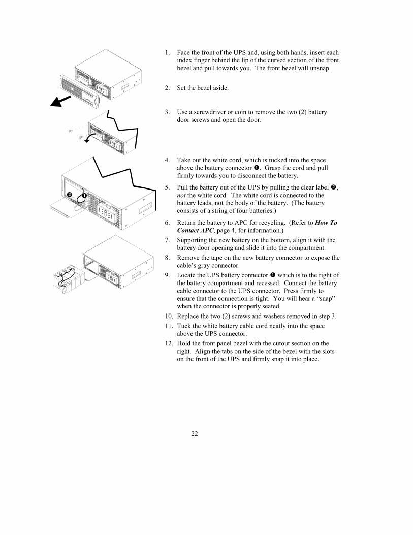
1. Face the front of the UPS and, using both hands, insert eachindex finger behind the lip of the curved section of the frontbezel and pull towards you. The front bezel will unsnap.
2. Set the bezel aside.
3. Use a screwdriver or coin to remove the two (2) batterydoor screws and open the door.
4. Take out the white cord, which is tucked into the spaceabove the battery connector �. Grasp the cord and pullfirmly towards you to disconnect the battery.
5. Pull the battery out of the UPS by pulling the clear label �,not the white cord. The white cord is connected to thebattery leads, not the body of the battery. (The batteryconsists of a string of four batteries.)
6. Return the battery to APC for recycling. (Refer to How ToContact APC, page 4, for information.)
7. Supporting the new battery on the bottom, align it with thebattery door opening and slide it into the compartment.
8. Remove the tape on the new battery connector to expose thecable’s gray connector.
9. Locate the UPS battery connector � which is to the right ofthe battery compartment and recessed. Connect the batterycable connector to the UPS connector. Press firmly toensure that the connection is tight. You will hear a “snap”when the connector is properly seated.
10. Replace the two (2) screws and washers removed in step 3.11. Tuck the white battery cable cord neatly into the space
above the UPS connector.12. Hold the front panel bezel with the cutout section on the
right. Align the tabs on the side of the bezel with the slotson the front of the UPS and firmly snap it into place.
��

23
TroubleshootingUse the chart below to solve minor UPS installation problems. Contact APC Technical SupportStaff for assistance with complex UPS problems. See How To Contact APC, page 4, for alocation near you.
Problem and Possible Cause SolutionUPS will not turn on.• ON button not pushed. Press the ON button once to power the UPS and the load.• UPS not connected to AC
power supply.Check that the power cable from the UPS to the utilitypower supply is securely connected at both ends.
• UPS input circuit breakertripped.
Reduce the load on the UPS by unplugging equipment andreset the circuit breaker (on back of UPS) by pressing theplunger back in.
• Very low or no utilityvoltage.
Check the AC power supply to the UPS with a table lamp.If very dim, have the utility voltage checked.
• Battery not connectedproperly.
Confirm the battery connections.
UPS will not turn off.• Internal UPS fault. Do not attempt to use the UPS. Unplug the UPS and have it
serviced immediately.UPS operates on-battery although normal line voltage exists.• UPS’s input circuit breaker
tripped.Reduce the load on the UPS by unplugging equipment andreset the circuit breaker (on back of UPS) by pressing theplunger back in.
• Very high, low, or distortedline voltage. Inexpensivefuel powered generators candistort the voltage.
Move the UPS to a different outlet on a different circuit.Test the input voltage with the utility voltage display. Ifacceptable to the load, reduce the UPS’s sensitivity. SeeVoltage Sensitivity, page 16, for procedures.
UPS beeps occasionally.• Normal UPS operation. None. The UPS is protecting the load.UPS does not provide expected backup time.• The UPS’s battery is weak
due to recent outage or isnear the end of its servicelife.
Charge the battery. Batteries require recharging afterextended outages. Also, they wear faster when put intoservice often or when operated at elevated temperatures. Ifthe battery is near the end of its service life, considerreplacing the battery even if the replace battery indicator isnot yet lit.
• The UPS is overloaded. Check the UPS’s load display. Unplug less neededequipment, such as printers.
Front panel indicators flash sequentially• The UPS has been shut down
remotely through software oran optional accessory card.
None. The UPS will restart automatically when utilitypower returns.
24
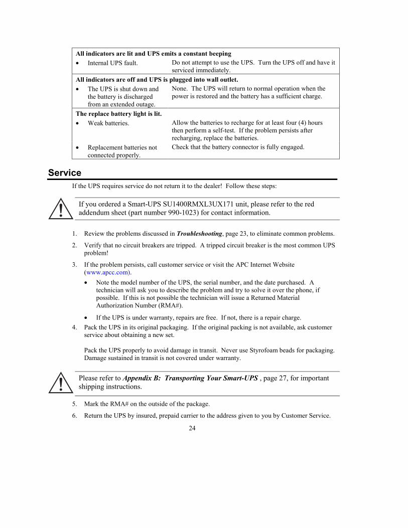
All indicators are lit and UPS emits a constant beeping• Internal UPS fault. Do not attempt to use the UPS. Turn the UPS off and have it
serviced immediately.All indicators are off and UPS is plugged into wall outlet.• The UPS is shut down and
the battery is dischargedfrom an extended outage.
None. The UPS will return to normal operation when thepower is restored and the battery has a sufficient charge.
The replace battery light is lit.• Weak batteries. Allow the batteries to recharge for at least four (4) hours
then perform a self-test. If the problem persists afterrecharging, replace the batteries.
• Replacement batteries notconnected properly.
Check that the battery connector is fully engaged.
ServiceIf the UPS requires service do not return it to the dealer! Follow these steps:
If you ordered a Smart-UPS SU1400RMXL3UX171 unit, please refer to the redaddendum sheet (part number 990-1023) for contact information.
1. Review the problems discussed in Troubleshooting, page 23, to eliminate common problems.
2. Verify that no circuit breakers are tripped. A tripped circuit breaker is the most common UPSproblem!
3. If the problem persists, call customer service or visit the APC Internet Website(www.apcc.com).• Note the model number of the UPS, the serial number, and the date purchased. A
technician will ask you to describe the problem and try to solve it over the phone, ifpossible. If this is not possible the technician will issue a Returned MaterialAuthorization Number (RMA#).
• If the UPS is under warranty, repairs are free. If not, there is a repair charge.4. Pack the UPS in its original packaging. If the original packing is not available, ask customer
service about obtaining a new set.
Pack the UPS properly to avoid damage in transit. Never use Styrofoam beads for packaging.Damage sustained in transit is not covered under warranty.
Please refer to Appendix B: Transporting Your Smart-UPS , page 27, for importantshipping instructions.
5. Mark the RMA# on the outside of the package.
6. Return the UPS by insured, prepaid carrier to the address given to you by Customer Service.

25
APPENDIX A: SPECIFICATIONS1400 VA (SU1400RMXL3U)
Normal input voltage 120 Vac single phase, 50 or 60 Hz (auto-selectable)Input plug NEMA 5-15P 6 ft line cordOutput receptacles (6) NEMA 5-15ROutput voltage range(configured via software)
103 – 132 Vac (by default)
Input protection Resettable circuit breakerTransfer time 2 ms typical, 4 ms maximumCapacity (maximum load) 1400 VA, 1050 WattsOn-battery output voltage Pure sine wave output at 120 Vac ±5%, -10% after low battery
warning, synchronized to utility lineOn-battery frequency 50 or 60 Hz ±0.1 Hz: unless synchronized to utility during
brownoutVoltage boost andVoltage trim operation
On-line operation for input 93 to 145 Vac will have output 103to 132 Vac. Voltage Boost increases voltage 10% above inputif 103 to 103 Vac, Voltage Trim reduces voltages 10% belowinput if 132 to 145 Vac. Transfer points are user adjustable
using software.Load power factor range,crest factor range
0.5 to 1.0<5
Surge energy rating,peak current capability
480 Joules6.5 kA
Normal, common mode clampingresponse time
0 ns, <5 ns, typical
Normal mode surge voltage let through(IEEE 587 CatA 6kV test)
<0.3% of peak, typical
Normal/common mode noisesuppression at 1.0 MHz,3 MHz, and 10 MHz
63/58, 54/58, 46/33 db
Protection Overcurrent and short-circuit protected, latching shutdown onoverload
Noise filter Normal and common mode EMI/RFI suppression, 100 kHz to10 MHz
Battery type Four 12 V 9 AH Spill proof, maintenance free, sealed lead-acidTypical battery life 3 – 6 years, depending on number of discharge cycles and
ambient temperatureTypical recharge time 2 to 5 hours from total dischargeAmbient operation 10,000 ft (3000 meters) minimum elevation, 10 – 85% humidity
non-condensing, 32 to 104 °F (0 to 40 °C)Storage temperature -15 to +45 ºC (+5 to +113 ºF)
26
Storage relative humidity 0 to 95%, non-condensingStorage elevation 0 to +15,000 m (0 to +50,000 ft)Electromagnetic immunity IEC 801-2 level IV, 801-3 level III, 801-4 level IV, 801-5Audible noise at 1 m (3 ft) from thesurface of the unit
<48 dbA
Size (H x W x D) (3U) 5.12 in. x 17 in. x 15.5 in.(13.0 cm x 43.2 cm x 39.4 cm)
Weight - net (shipping) 70 lb (89 lb)31.8 kg (40.4 kg)
Safety approvals Listed to UL 1778, certified to CSA 107.1EMI verification FCC/DOC Class A certified
Due to continuous improvement, specifications are subject to change without notice.
Regulatory Agency Approvals
®
LISTED 42C2E95463 LR63938
Radio Frequency InterferenceThis equipment has been tested and found to comply with the limits for a Class A digital device,pursuant to part 15 of the FCC Rules. These limits are designed to provide reasonable protectionagainst harmful interference when the equipment is operated in a commercial environment. Thisequipment generates, uses, and can radiate radio frequency energy and, if not installed and used inaccordance with the instruction manual, may cause harmful interference to radio communications.Operation of this equipment in a residential area is likely to cause harmful interference in whichcase the user will be required to correct the interference at his own expense.
Shielded signal cables must be used with this product to ensure compliance with the Class A FCClimits.

27
APPENDIX B: TRANSPORTING YOUR SMART-UPSFollow these guidelines if you need to ship the UPS to another location. These guidelines applywhether you are transporting the UPS alone, rack mounted in an equipment cabinet, or installed ina system.
Always DISCONNECT THE BATTERIES before shipping the UPS to avoiddamage during transport. (U.S. Federal Regulation requires that batteries bedisconnected during shipment.) The batteries may remain in the UPS; they donot have to be removed.This requirement applies whether the UPS is shipped alone or installed in anequipment rack or system.
Graphics are not drawn to scale. They are shown for reference only.
The battery compartment is accessed from the front panel of the UPS.
1. Remove the front bezel by grasping the finger clips on the side ofthe bezel and carefully loosening the four (4) snaps.
2. Use a screwdriver or coin to remove the two battery door screwsand open the door.
3. Disconnect the front battery pack. Grasp the white cord and pullfirmly to disconnect the connector from the battery compartment.
4. Tuck the white cord (that serves as a handle for the connector)neatly on top of the battery pack.
5. Close the battery door and replace the two (2) screws removed instep 2.
6. Leave the front bezel off unless the UPS is being transported in arack.
Remember to connect the batteries once the UPS has arrived at its destination.
��