SMART STRUCTURES AND MATERIALS - SSDL|Home
38
SMART STRUCTURES AND MATERIALS 1 SMART STRUCTURES AND MATERIALS SMART SYSTEMS/ STRUCTURES Definition of Smart Systems/ Structures The definition of smart structures was a topic of controversy from the late 1970’s to the late 1980’s. In order to arrive at a consensus for major terminology, a special workshop was organised by the US Army Research Office in 1988, in which ‘sensors’, ‘actuators’, ‘control mechanism’ and ‘timely response’ were recognised as the four qualifying features of any smart system or structure (Rogers, 1988). In this workshop, following definition of smart systems/ structures was formally adopted (Ahmad, 1988). “A system or material which has built-in or intrinsic sensor(s), actuator(s) and control mechanism(s) whereby it is capable of sensing a stimulus, responding to it in a predetermined manner and extent, in a short/ appropriate time, and reverting to its original state as soon as the stimulus is removed” According to Vardan and Vardan (2000), smart system refers to a device which can sense changes in its environment and can make an optimal response by changing its material properties, geometry, mechanical or electromagnetic response. Both the sensor and the actuator functions with their appropriate feedback must be properly integrated. It should also be noted that if the response is too slow or too fast, the system could lose its application or could be dangerous (Takagi, 1990). Previously, the words ‘intelligent’, ‘adaptive’ and ‘organic’ were also used to characterize smart systems and materials. For example, Crawley and de Luis (1987) defined ‘intelligent structures’ as the structures possessing highly distributed actuators, sensors and processing networks. Similarly, Professor H. H. Robertshaw
Transcript of SMART STRUCTURES AND MATERIALS - SSDL|Home

SMART STRUCTURES AND MATERIALS
1
SMART STRUCTURES AND MATERIALS
SMART SYSTEMS/ STRUCTURES
Definition of Smart Systems/ Structures
The definition of smart structures was a topic of controversy from the late 1970’s to
the late 1980’s. In order to arrive at a consensus for major terminology, a special
workshop was organised by the US Army Research Office in 1988, in which
‘sensors’, ‘actuators’, ‘control mechanism’ and ‘timely response’ were recognised
as the four qualifying features of any smart system or structure (Rogers, 1988). In
this workshop, following definition of smart systems/ structures was formally
adopted (Ahmad, 1988).
“A system or material which has built-in or intrinsic sensor(s), actuator(s) and
control mechanism(s) whereby it is capable of sensing a stimulus, responding to it
in a predetermined manner and extent, in a short/ appropriate time, and reverting
to its original state as soon as the stimulus is removed”
According to Vardan and Vardan (2000), smart system refers to a device which can
sense changes in its environment and can make an optimal response by changing its
material properties, geometry, mechanical or electromagnetic response. Both the
sensor and the actuator functions with their appropriate feedback must be properly
integrated. It should also be noted that if the response is too slow or too fast, the
system could lose its application or could be dangerous (Takagi, 1990).
Previously, the words ‘intelligent’, ‘adaptive’ and ‘organic’ were also used to
characterize smart systems and materials. For example, Crawley and de Luis (1987)
defined ‘intelligent structures’ as the structures possessing highly distributed
actuators, sensors and processing networks. Similarly, Professor H. H. Robertshaw

SMART STRUCTURES AND MATERIALS
2
preferred the term ‘organic’ (Rogers, 1988) which suggests similarity to biological
processes. The human arm, for example, is like a variable stiffness actuator with a
control law (intelligence). However, many participants at the US Army Research
Office Workshop (e.g. Rogers et al., 1988) sought to differentiate the terms
‘intelligent’, ‘adaptive’ and ‘organic’ from the term ‘smart’ by highlighting their
subtle differences with the term ‘smart’. The term ‘intelligence’, for example, is
associated with abstract thought and learning, and till date has not been
implemented in any form of adaptive and sensing material or structure. However,
still many researchers use the terms ‘smart’ and ‘intelligent’ almost interchangeably
(e.g. In the U.S.-Japan Workshop: Takagi, 1990; Rogers, 1990), though ‘adaptive’
and ‘organic’ have become less popular.
The idea of ‘smart’ or ‘intelligent’ structures has been adopted from nature, where
all the living organisms possess stimulus-response capabilities (Rogers, 1990). The
aim of the ongoing research in the field of smart systems/ structures is to enable
such a structure or system mimic living organisms, which possess a system of
distributed sensory neurons running all over the body, enabling the brain to monitor
the condition of the various body parts. However, the smart systems are much
inferior to the living beings since their level of intelligence is much primitive.
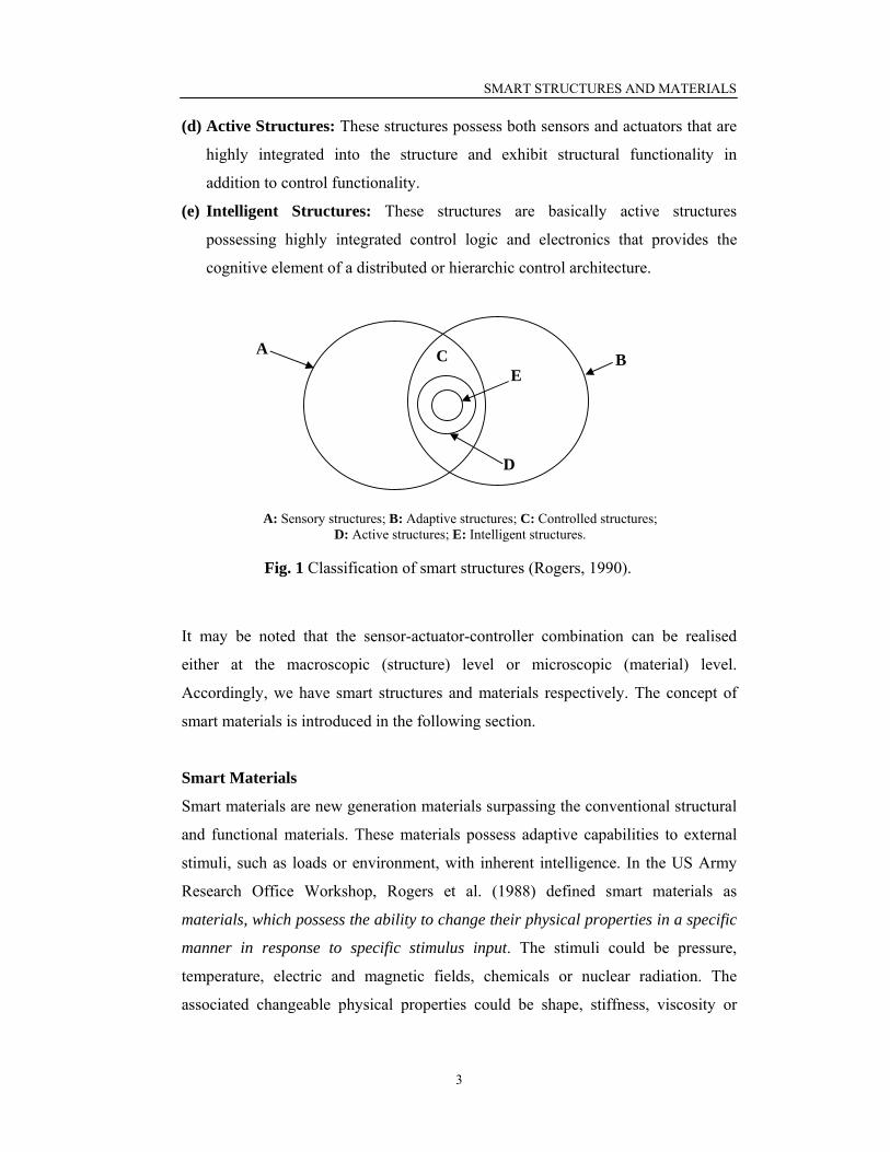
In conjunction with smart or intelligent structures, Rogers (1990) defined following
additional terms, which are meant to classify the smart structures further, based on
the level of sophistication. The relationship between these structure types is clearly
explained in Fig. 1
(a) Sensory Structures: These structures possess sensors that enable the
determination or monitoring of system states/ characteristics.
(b) Adaptive Structures: These structures possess actuators that enable the
alteration of system states or characteristics in a controlled manner.
(c) Controlled Structures: These result from the intersection of the sensory and
the adaptive structures. These possess both sensors and actuators integrated in
feedback architecture for the purpose of controlling the system states or
characteristics.
SMART STRUCTURES AND MATERIALS
3
(d) Active Structures: These structures possess both sensors and actuators that are
highly integrated into the structure and exhibit structural functionality in
addition to control functionality.
(e) Intelligent Structures: These structures are basically active structures
possessing highly integrated control logic and electronics that provides the
cognitive element of a distributed or hierarchic control architecture.
It may be noted that the sensor-actuator-controller combination can be realised
either at the macroscopic (structure) level or microscopic (material) level.
Accordingly, we have smart structures and materials respectively. The concept of
smart materials is introduced in the following section.
Smart Materials
Smart materials are new generation materials surpassing the conventional structural
and functional materials. These materials possess adaptive capabilities to external
stimuli, such as loads or environment, with inherent intelligence. In the US Army
Research Office Workshop, Rogers et al. (1988) defined smart materials as
materials, which possess the ability to change their physical properties in a specific
manner in response to specific stimulus input. The stimuli could be pressure,
temperature, electric and magnetic fields, chemicals or nuclear radiation. The
associated changeable physical properties could be shape, stiffness, viscosity or
A B C
D
E
A: Sensory structures; B: Adaptive structures; C: Controlled structures; D: Active structures; E: Intelligent structures.
Fig. 1 Classification of smart structures (Rogers, 1990).

SMART STRUCTURES AND MATERIALS
4
damping. This kind of ‘smartness’ is generally programmed by material
composition, special processing, introduction of defects or by modifying the micro-
structure, so as to adapt to the various levels of stimuli in a controlled fashion. Like
smart structures, the terms ‘smart’ and ‘intelligent’ are used interchangeably for
smart materials. Takagi (1990) defined intelligent materials as the materials which
respond to environmental changes at the most optimum conditions and manifest
their own functions according to the environment. The feedback functions within
the material are combined with properties and functions of the materials.
Optical fibres, piezo-electric polymers and ceramics, electro-rheological (ER)
fluids, magneto-strictive materials and shape memory alloys (SMAs) are some of
the smart materials. Fig. 2 shows the associated ‘stimulus’ and ‘response’ of
common smart materials. Because of their special ability to respond to stimuli, they
are finding numerous applications in the field of sensors and actuators. A very
detailed description of smart materials is covered by Gandhi and Thompson (1992).
Active and Passive Smart Materials
Smart materials can be either active or passive. Fairweather (1998) defined active
smart materials as those materials which possess the capacity to modify their
geometric or material properties under the application of electric, thermal or
magnetic fields, thereby acquiring an inherent capacity to transduce energy.
Piezoelectric materials, SMAs, ER fluids and magneto-strictive materials are active
smart materials. Being active, they can be used as force transducers and actuators.
For example, the SMA has large recovery force, of the order of 700 MPa (105 psi)
(Kumar, 1991), which can be utilized for actuation. Similarly piezoelectric
materials, which convert electric energy into mechanical force, are also ‘active’.
The smart materials, which are not active, are called passive smart materials.
Although smart, these lack the inherent capability to transduce energy. Fibre optic
material is a good example of a passive smart material. Such materials can act as
sensors but not as actuators or transducers.

SMART STRUCTURES AND MATERIALS
5
Applications of Piezoelectric Materials
Since this thesis is primarily concerned with piezoelectric materials, some typical
applications of these materials are briefly described here. Traditionally,
piezoelectric materials have been well-known for their use in accelerometers, strain
sensors (Sirohi and Chopra, 2000b), emitters and receptors of stress waves
(Giurgiutiu et al., 2000; Boller, 2002), distributed vibration sensors (Choi and
Chang, 1996; Kawiecki, 1998), actuators (Sirohi and Chopra, 2000a) and pressure
transducers (Zhu, 2003). However, since the last decade, the piezoelectric materials,
their derivative devices and structures have been increasingly employed in turbo-
machinery actuators, vibration dampers and active vibration control of stationary/
moving structures (e.g. helicopter blades, Chopra, 2000). They have been shown to
be very promising in active structural control of lab-sized structures and machines
(e.g. Manning et al., 2000; Song et al., 2002). Structural control of large structures
has also been attempted (e.g. Kamada et al., 1997). Other new applications include
underwater acoustic absorption, robotics, precision positioning and smart skins for
submarines (Kumar, 1991). Skin-like tactile sensors utilizing piezoelectric effect for
Fig. 2 Common smart materials and associated stimulus-response.
Electric field Change in viscosity (Internal damping)
Heat Original Memorized Shape
Magnetic field Mechanical Strain
Optical Fibre Temperature, pressure,
mechanical strain Change in Opto- Electronic signals
(1) Stress (1) Electric Charge
(2) Electric field (2) Mechanical strain Piezoelectric
Material
Shape Memory Alloy
Electro-rheological Fluid
Magneto-strictive material

SMART STRUCTURES AND MATERIALS
6
sensing temperatures and pressures have been reported (Rogers, 1990). Very
recently, the piezoelectric materials have been employed to produce micro and nano
scale systems and wireless inter digital transducers (IDT) using advanced embedded
system technologies, which are set to find numerous applications in micro-
electronics, bio-medical and SHM (Varadan, 2002; Lynch et al., 2003b). Recent
research is also exploring the development of versatile piezo-fibres, which can be
integrated with composite structures for actuation and SHM (Boller, 2002).
The most striking application of the piezoelectric materials in SHM has been in the
form of EMI technique. This is the main focus of the present thesis and details will
be covered in the subsequent sections.
Smart Materials: Future Applications
Seasoned researchers often share visionary ideas about the future of smart materials
in conferences and seminars. According to Prof. Rogers (Rogers, 1990), following
advancements could be possible in the field of smart materials and structures.
• Materials which can restrain the propagation of cracks by automatically
producing compressive stresses around them (Damage arrest).
• Materials, which can discriminate whether the loading is static or shock and can
generate a large force against shock stresses (Shock absorbers).
• Materials possessing self-repairing capabilities, which can heal damages in due
course of time (Self-healing materials).
• Materials which are usable up to ultra-high temperatures (such as those
encountered by space shuttles when they re-enter the earth’s atmosphere from
outer space), by suitably changing composition through transformation (thermal
mitigation).
Takagi (1990) similarly projected the development of more functional and higher
grade materials with recognition, discrimination, adjustability, self-diagnostics and
self-learning capabilities.

SMART STRUCTURES AND MATERIALS
7
PIEZOELECTRICITY AND PIEZOELECTRIC MATERIALS
The word ‘piezo’ is derived from a Greek word meaning pressure. The phenomenon
of piezoelectricity was discovered in 1880 by Pierre and Paul-Jacques Curie. It
occurs in non-centro symmetric crystals, such as quartz (SiO2), Lithium Niobate
(LiNbO3), PZT [Pb(Zr1-xTix)O3)] and PLZT [(Pb1-xLax)(Zr1-yTiy)O3)], in which
electric dipoles (and hence surface charges) are generated when the crystals are
loaded with mechanical deformations. The same crystals also exhibit the converse
effect; that is, they undergo mechanical deformations when subjected to electric
fields.
In centro-symmetric crystals, the act of deformation does not induce any dipole
moment, as shown in Fig. 3. However, in non-centro symmetric crystals, this
leads to a net dipole moment, as illustrated in Fig. 4. Similarly, the act of applying
an electric field induces mechanical strains in the non-centro symmetric crystals.
μ = 0 μ = 0
Fig. 3 Centro-symmetric crystals: the act of stretching does not cause any
dipole moment (μ = Dipole moment).
Fig. 4 Noncentro-symmetric crystals: the act of stretching causes dipole moment in
the crystal (μ = Dipole moment).
μ = 0 μ ≠ 0

SMART STRUCTURES AND MATERIALS
8
Constitutive Relations
The constitutive relations for piezoelectric materials, under small field condition are
(IEEE standard, 1987)
mdimj
Tiji TdED += ε (1)
mEkmj
cjkk TsEdS += (1)
Eq. (1) represents the so called direct effect (that is stress induced electrical charge)
whereas Eq. (2) represents the converse effect (that is electric field induced
mechanical strain). Sensor applications are based on the direct effect, and actuator
applications are based on the converse effect. When the sensor is exposed to a
stress field, it generates proportional charge in response, which can be measured.
On the other hand, the actuator is bonded to the structure and an external field is
applied to it, which results in an induced strain field. In more general terms, Eqs.
(2.1) and (2.2) can be rewritten in the tensor form as (Sirohi and Chopra, 2000b)
⎥⎦
⎤⎢⎣
⎡
⎥⎥⎦
⎤
⎢⎢⎣
⎡=⎥
⎦
⎤⎢⎣
⎡TE
sdd
SD
Ec
dTε (3)
where [D] (3x1) (C/m2) is the electric displacement vector, [S] (3x3) the second
order strain tensor, [E] (3x1) (V/m) the applied external electric field vector and [T]
(3x3) (N/m2) the stress tensor. Accordingly, [ Tε ] (F/m) is the second order
dielelectric permittivity tensor under constant stress, [dd] (C/N) and [dc] (m/V) the
third order piezoelectric strain coefficient tensors, and [ Es ] (m2/N) the fourth order
elastic compliance tensor under constant electric field.
Taking advantage of the symmetry of the stress and the strain tensors, these can be
reduced from a second order (3x3) tensor form to equivalent vector forms, (6x1) in
size. Thus, TSSSSSSS ],,,,,[][ 123123332211= and similarly,
TTTTTTTT ],,,,,[][ 123123332211= . Accordingly, the piezoelectric strain coefficients
can be reduced to second order tensors (from third order tensors), as [dd] (3x6) and
[dc] (6x3). The superscripts ‘d’ and ‘c’ indicate the direct and the converse effects
respectively. Similarly, the fourth order elastic compliance tensor [ Es ] can be

SMART STRUCTURES AND MATERIALS
9
reduced to (6x6) second order tensor. The superscripts ‘T’ and ‘E’ indicate that the
parameter has been measured at constant stress (free mechanical boundary) and
constant electric field (short-circuited) respectively. A bar above any parameter
signifies that it is complex in nature (i.e. measured under dynamic conditions). The
piezoelectric strain coefficient cjkd defines mechanical strain per unit electric field
under constant (zero) mechanical stress and dimd defines electric displacement per
unit stress under constant (zero) electric field. In practice, the two coefficients are
numerically equal. In cjkd or d
imd , the first subscript denotes the direction of the
electric field and second the direction of the associated mechanical strain. For
example, the term d31 signifies that the electric field is applied in the direction ‘3’
and the strain is measured in direction ‘1’.
If static electric field is applied under the boundary condition that the crystal is free
to deform, no mechanical stresses will develop. Similarly, if the stress is applied
under the condition that the electrodes are short-circuited, no electric field (or
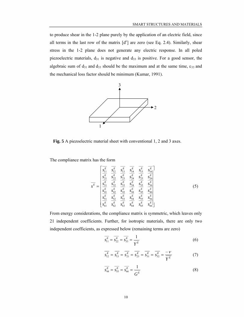
surface charges) will develop. For a sheet of piezoelectric material, as shown in Fig.
5, the poling direction is usually along the thickness and is denoted as 3-axis. The 1-
axis and 2-axis are in the plane of the sheet.
The matrix [dc] depends on crystal structure. For example, it is different for PZT
and quartz, as given by (Zhu, 2003)
⎥⎥⎥⎥⎥⎥⎥⎥
⎦
⎤
⎢⎢⎢⎢⎢⎢⎢⎢
⎣
⎡
=
0000000
000000
15
24
33
32
31
dd
ddd
d c (PZT) ,
⎥⎥⎥⎥⎥⎥⎥⎥
⎦
⎤
⎢⎢⎢⎢⎢⎢⎢⎢
⎣
⎡
−−
−
02000000000000
11
14
14
11
11
dd
d
dd
(quartz) (4)
where the coefficients d31, d32 and d33 relate the normal strain in the 1, 2 and 3
directions respectively to an electric field along the poling direction 3. For PZT
crystals, the coefficient d15 relates the shear strain in the 1-3 plane to the field E1 and
d24 relates the shear strain in the 2-3 plane to the electric field E2. It is not possible
SMART STRUCTURES AND MATERIALS
10
to produce shear in the 1-2 plane purely by the application of an electric field, since
all terms in the last row of the matrix [dc] are zero (see Eq. 2.4). Similarly, shear
stress in the 1-2 plane does not generate any electric response. In all poled
piezoelectric materials, d31 is negative and d33 is positive. For a good sensor, the
algebraic sum of d31 and d33 should be the maximum and at the same time, ε33 and
the mechanical loss factor should be minimum (Kumar, 1991).
The compliance matrix has the form
⎥⎥⎥⎥⎥⎥⎥⎥
⎦
⎤
⎢⎢⎢⎢⎢⎢⎢⎢
⎣
⎡
=
EEEEEE
EEEEEE
EEEEEE
EEEEEE
EEEEEE
EEEEEE
E
ssssssssssssssssssssssssssssssssssss
s
666564636261
565554535251
464544434241
363534333231
262524232221
161514131211
(5)
From energy considerations, the compliance matrix is symmetric, which leaves only
21 independent coefficients. Further, for isotropic materials, there are only two
independent coefficients, as expressed below (remaining terms are zero)
E
EEE
Ysss 1
332211 === (6)
E
EEEEEE
Yssssss ν−
====== 323123211312 (7)
E
EEE
Gsss 1
665544 === (8)
1
2
3
Fig. 5 A piezoelectric material sheet with conventional 1, 2 and 3 axes.
SMART STRUCTURES AND MATERIALS
11
where EY is the complex Young’s modulus of elasticity (at constant electric field),
EG the complex shear modulus (at constant electric field) and ν the Poisson’s ratio.
It may be noted that the static moduli, YE and GE, are related by
)1(2 ν+
=E
E YG (9)
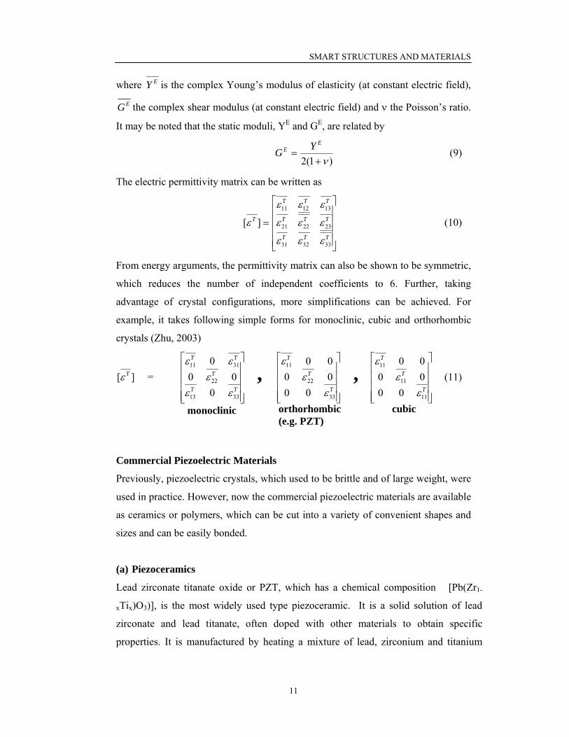
The electric permittivity matrix can be written as
⎥⎥⎥⎥
⎦
⎤
⎢⎢⎢⎢
⎣
⎡
=TTT
TTT
TTT
T
333231
232221
131211
][
εεε
εεε
εεε
ε (10)
From energy arguments, the permittivity matrix can also be shown to be symmetric,
which reduces the number of independent coefficients to 6. Further, taking
advantage of crystal configurations, more simplifications can be achieved. For
example, it takes following simple forms for monoclinic, cubic and orthorhombic
crystals (Zhu, 2003)
][ Tε =
⎥⎥⎥⎥
⎦
⎤
⎢⎢⎢⎢
⎣
⎡
TT
T
TT
3313
22
3111
000
0
εεε
εε ,
⎥⎥⎥⎥
⎦
⎤
⎢⎢⎢⎢
⎣
⎡
T
T
T
33
22
11
000000
εε
ε ,
⎥⎥⎥⎥
⎦
⎤
⎢⎢⎢⎢
⎣
⎡
T
T
T
11
11
11
000000
εε
ε (11)
Commercial Piezoelectric Materials
Previously, piezoelectric crystals, which used to be brittle and of large weight, were
used in practice. However, now the commercial piezoelectric materials are available
as ceramics or polymers, which can be cut into a variety of convenient shapes and
sizes and can be easily bonded.
(a) Piezoceramics
Lead zirconate titanate oxide or PZT, which has a chemical composition [Pb(Zr1-
xTix)O3)], is the most widely used type piezoceramic. It is a solid solution of lead
zirconate and lead titanate, often doped with other materials to obtain specific
properties. It is manufactured by heating a mixture of lead, zirconium and titanium
monoclinic orthorhombic (e.g. PZT)
cubic
SMART STRUCTURES AND MATERIALS
12
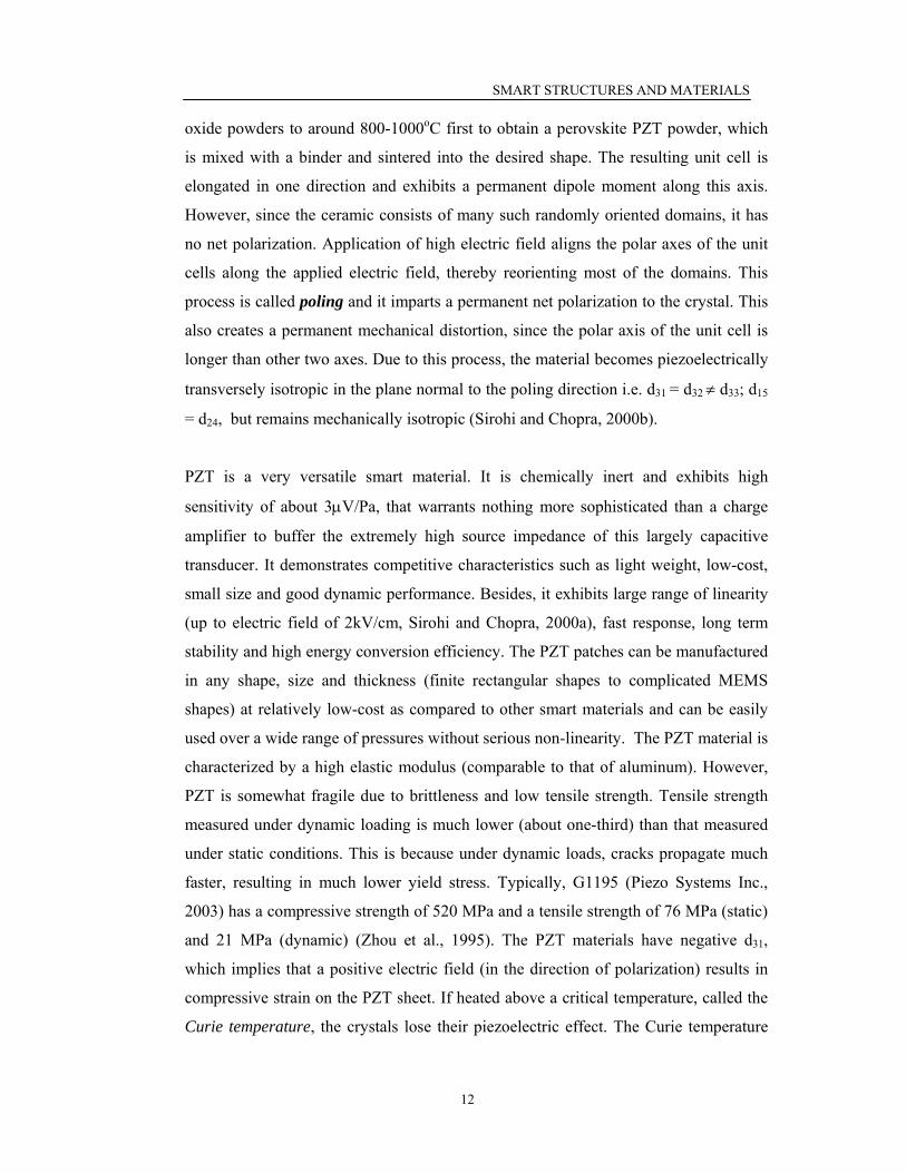
oxide powders to around 800-1000oC first to obtain a perovskite PZT powder, which
is mixed with a binder and sintered into the desired shape. The resulting unit cell is
elongated in one direction and exhibits a permanent dipole moment along this axis.
However, since the ceramic consists of many such randomly oriented domains, it has
no net polarization. Application of high electric field aligns the polar axes of the unit
cells along the applied electric field, thereby reorienting most of the domains. This
process is called poling and it imparts a permanent net polarization to the crystal. This
also creates a permanent mechanical distortion, since the polar axis of the unit cell is
longer than other two axes. Due to this process, the material becomes piezoelectrically
transversely isotropic in the plane normal to the poling direction i.e. d31 = d32 ≠ d33; d15
= d24, but remains mechanically isotropic (Sirohi and Chopra, 2000b).
PZT is a very versatile smart material. It is chemically inert and exhibits high
sensitivity of about 3μV/Pa, that warrants nothing more sophisticated than a charge
amplifier to buffer the extremely high source impedance of this largely capacitive
transducer. It demonstrates competitive characteristics such as light weight, low-cost,
small size and good dynamic performance. Besides, it exhibits large range of linearity
(up to electric field of 2kV/cm, Sirohi and Chopra, 2000a), fast response, long term
stability and high energy conversion efficiency. The PZT patches can be manufactured
in any shape, size and thickness (finite rectangular shapes to complicated MEMS
shapes) at relatively low-cost as compared to other smart materials and can be easily
used over a wide range of pressures without serious non-linearity. The PZT material is
characterized by a high elastic modulus (comparable to that of aluminum). However,
PZT is somewhat fragile due to brittleness and low tensile strength. Tensile strength
measured under dynamic loading is much lower (about one-third) than that measured
under static conditions. This is because under dynamic loads, cracks propagate much
faster, resulting in much lower yield stress. Typically, G1195 (Piezo Systems Inc.,
2003) has a compressive strength of 520 MPa and a tensile strength of 76 MPa (static)
and 21 MPa (dynamic) (Zhou et al., 1995). The PZT materials have negative d31,
which implies that a positive electric field (in the direction of polarization) results in
compressive strain on the PZT sheet. If heated above a critical temperature, called the
Curie temperature, the crystals lose their piezoelectric effect. The Curie temperature

SMART STRUCTURES AND MATERIALS
13
typically varies from 150oC to 350oC for most commercial PZT crystals. When
exposed to high electric fields (>12 kV/cm), opposite to the poling direction, the PZT
loses most of its piezoelectric capability. This is called deploing and is accompanied
by a permanent change in the dimensions of the sample.
Due to high stiffness, the PZT sheets are good actuators. They also exhibit high
strain coefficients, due to which they can act as good sensors also. These features
make the PZT materials very suitable for use as collocated actuators and sensors.
They are used in deformable mirrors, mechanical micropositioners, impact devices
and ultrasonic motors (Kumar, 1991), sonic and ultrasonic sensors, filters and
resonators, signal processing devices, igniters and voltage transformers (Zhu, 2003),
to name only a few. For achieving large displacements, multi layered PZT systems
can be manufactured, such as stack, moonie and bimorph actuators.
However, due to their brittleness, the PZT sheets cannot withstand bending and also
exhibit poor conformability to curved surfaces. This is the main limitation with PZT
materials. In addition, the PZT materials show considerable fluctuation of their
electric properties with temperature. Also, soldering wires to the electroded
piezoceramics requires special skill and often results in broken elements, unreliable
connections or localized thermal depoling of the elements. As a solution to these
problems, active piezoceramic composite actuators (Smart Materials Corporation),
active fibre composites (Massachusetts Institute of Technology) and macro fibre
composites, MFCs (NASA, Langley Centre) have been developed recently (Park et
al., 2003a). The MFCs have been commercially available since 2003. These new
types of PZTs are low-cost, damage tolerant, can conform to curved surface and are
embeddable. In addition, Active Control eXperts, Inc. (ACX), now owned by Mide
Technology Corporation, has developed a packaging technology in which one or
more PZT elements are laminated between sheets of polymer flexible printed
circuitry. This provides the much robustness, reliability and ease of use. The
packaged sensors are commercially called QuickPack® actuators (Mide Technology
Corporation, 2004). These are now widely used as vibration dampers in sporting
goods, buzzer alerts, drivers for flat speakers and more recently in automotive and

SMART STRUCTURES AND MATERIALS
14
aerospace components (Pretorius et al., 2004). However, these are presently many
times expensive than raw PZT patches.
(b) Piezopolymers
The most common commercial piezopolymer is the Polyvinvylidene Fluoride
(PVDF). It is made up of long chains of the repeating monomer (-CH2-CF2-) each
of which has an inherent dipole moment. PVDF film is manufactured by
solidification from the molten phase, which is then stretched in a particular
direction and poled. The stretching process aligns the chains in one direction.
Combined with poling, this imparts a permanent dipole moment to the film.
Because of stretching, the material is rendered piezoelectrically orthotropic, that is
d31 ≠ d32, where ‘1’ is the stretching direction. However, it still remains
mechanically isotropic.
The PVDF material is characterized by low stiffness (Young’s modulus is 1/12th
that of aluminum). Hence, the PVDF sensors are not likely to modify the stiffness
of the host structure due to their own stiffness. Also, PVDF films can be shaped as
desired according to the intended application. Being polymer, it can be formed into
very thin sheets and adhered to curved surfaces also due to its flexibility. These
characteristics make PVDF films more attractive for sensor applications, in spite of
their low piezoelectric coefficients (approximately 1/10th of PZT). It has been
shown by Sirohi and Chopra (2000b) that shear lag effect is negligible in PVDF
sensors.
Piezo-rubber, which consists of fine particles of PZT material embedded in
synthetic rubber (Rogers, 1990), has appeared as an alternative for PVDF. The
piezo-rubber shows much higher electrical output due to larger thickness, which is
not possible in PVDF. The piezo-rubber is used in piezoelectric coaxial cable as a
vehicle sensor. It has much longer life and is immune to rain water.

SMART STRUCTURES AND MATERIALS
15
PIEZOELECTRIC MATERIALS AS MECHATRONIC IMPEDANCE
TRANSDUCERS (MITs) FOR SHM
The term mechatronic impedance transducer (MIT) was coined by Park (2000). A
mechatronic transducer is defined as a transducer which can convert electrical
energy into mechanical energy and vice versa. The piezoceramic (PZT) materials,
because of the direct (sensor) and converse (actuator) capabilities, are mechatronic
transducers. When used as MIT, their electromechanical impedance characteristics
are utilized for diagnosing the condition of the structures and the same patch plays
the dual roles, as an actuator as well as a sensor. The technique utilizing the PZT
based MIT for SHM/ NDE has evolved during the last nine years and is called as
the electro-mechanical impedance (EMI) technique in the literature. The following
sections describe the various aspects of this technique in detail.
Physical Principles
The EMI technique is very similar to the conventional global dynamic response
techniques described previously. The major difference is with respect to the
frequency range employed, which is typically 30-400kHz in EMI technique, against
less than 100Hz in the case of the global dynamic methods.
In the EMI technique, a PZT patch is bonded to the surface of the monitored
structure using a high strength epoxy adhesive, and electrically excited via an
impedance analyzer. In this configuration, the PZT patch essentially behaves as a
Fig. 6 Modelling PZT-structure interaction.
(a) A PZT patch bonded to structure under electric excitation.
(b) Interaction model of PZT patch and host structure.
(a) (b)
Alternating electric field source
l l
Point of mechanical fixity
PZT Patch
3 (z) 1 (x)
Host structure
2 (y)
PZT patch
Structural Impedance l
h w
E3 1
3 2
l
Z Z

SMART STRUCTURES AND MATERIALS
16
thin bar undergoing axial vibrations and interacting with the host structure, as
shown in Fig. 6 (a). The PZT patch-host structure system can be modelled as a
mechanical impedance (due the host structure) connected to an axially vibrating
thin bar (the patch), as shown in Fig. 6(b). The patch in this figure expands and
contracts dynamically in direction ‘1’ when an alternating electric field E3 (which is
spatially uniform i.e. ∂E3/∂x = ∂E3/∂y = 0) is applied in the direction ‘3’. The patch
has half-length ‘l’, width ‘w’ and thickness ‘h’. The host structure is assumed to be
a skeletal structure, that is, composed of one-dimensional members with their
sectional properties (area and moment of inertia) lumped along their neutral axes.
Therefore, the vibrations of the PZT patch in direction ‘2’ can be ignored. At the
same time, the PZT loading in direction ‘3’ is neglected by assuming the
frequencies involved to be much less than the first resonant frequency for thickness
vibrations. The vibrating patch is assumed infinitesimally small and to possess
negligible mass and stiffness as compared to the host structure. The structure can
therefore be assumed to possess uniform dynamic stiffness over the entire bonded
area. The two end points of the patch can thus be assumed to encounter equal
mechanical impedance, Z, from the structure, as shown in Fig. 2.8 (b). Under this
condition, the PZT patch has zero displacement at the mid-point (x= 0), irrespective
of the location of the patch on the host structure. Under these assumptions, the
constitutive relations (Eqs. 1 and 2) can be simplified as (Ikeda, 1990)
1313333 TdED T += ε (13)
3311
1 EdYTS
E+= (14)
where S1 is the strain in direction ‘1’, D3 the electric displacement over the PZT
patch, d31 the piezoelectric strain coefficient and T1 the axial stress in direction ‘1’.
)1( jYY EE η+= is the complex Young’s modulus of elasticity of the PZT patch at
constant electric field and )1(3333 jTT δεε −= is the complex electric permittivity (in
direction ‘3’) of the PZT material at constant stress, where 1−=j . Here, η and δ
denote respectively the mechanical loss factor and the dielectric loss factor of the
PZT material.

SMART STRUCTURES AND MATERIALS
17
The one-dimensional vibrations of the PZT patch are governed by the following
differential equation (Liang et al., 1994), derived based on dynamic equilibrium of
the PZT patch.
2
2
2
2
tu
xuY E
∂∂
=∂∂ ρ (15)
where ‘u’ is the displacement at any point on the patch in direction ‘1’. Solution of
the governing differential equation by the method of separation of variables yields tjexBxAu ωκκ )cossin( += (16)
where κ is the wave number, related to the angular frequency of excitation ω, the
density ρ and the complex Young’s modulus of elasticity of the patch by
EYρωκ = (17)
Application of the mechanical boundary condition that at x = 0 (mid point of the
PZT patch), u = 0 yields B = 0.
Hence, strain in PZT patch xAexuxS tj κκω cos)(1 =∂∂
= (18)
and velocity xeAjtuxu tj κω ω sin)( =∂∂
=& (19)
Further, by definition, the mechanical impedance Z of the structure is related to the
axial force F in the PZT patch by
)()(1)( lxlxlx uZwhTF === −== & (20)
where the negative sign signifies the fact that a positive displacement (or velocity)
causes compressive force in the PZT patch (Liang et al., 1993, 1994). Making use
of Eq. (2.14) and substituting the expressions for strain and velocity from Eqs.
(2.18) and (2.19) respectively, we can derive
))(cos(
31
a
oa
ZZlhdVZA
+=
κκ (21)
where Za is the short-circuited mechanical impedance of the PZT patch, given by
)tan()( lj
YwhZ
E
a κωκ
= (22)

SMART STRUCTURES AND MATERIALS
18
Za is defined as the force required to produce unit velocity in the PZT patch in short
circuited condition (i.e. ignoring the piezoelectric effect) and ignoring the host
structure.
The electric current, which is the time rate of change of charge, can be obtained as
dxdyDjdxdyDIAA∫∫∫∫ == 33 ω& (23)
Making use of the PZT constitutive relation (Eq. 13), and integrating over the entire
surface of the PZT patch (-l to +l), we can obtain an expression for the
electromechanical admittance (the inverse of electro-mechanical impedance) as
⎥⎥⎦
⎤
⎢⎢⎣
⎡⎟⎠⎞
⎜⎝⎛
⎟⎟⎠
⎞⎜⎜⎝
⎛+
+−=l
lYdZZ
ZYdhwljY E
a
aET
κκεω tan)(2 2
3123133 (24)
This equation is same as that derived by Liang et al. (1994), except that an
additional factor of 2 comes into picture. This is due to the fact that Liang et al.
(1993, 1994) considered only one-half of the patch in their derivation.
In the EMI technique, this electro-mechanical coupling between the mechanical
impedance Z of the host structure and the electro-mechanical admittance Y is
utilized in damage detection. Z is a function of the structural parameters- the
stiffness, the damping and the mass distribution. Any damage to the structure will
cause these structural parameters to change, and hence alter the drive point
mechanical impedance Z. Assuming that the PZT parameters remain unchanged, the
electromechanical admittance Y will undergo a change and this serves as an
indicator of the state of health of the structure. Measuring Z directly may not be
feasible, but Y can be easily measured using any commercial electrical impedance
analyzer. Common damage types altering local structural impedance Z are cracks,
debondings, corrosion and loose connections (Esteban, 1996), to which the PZT
admittance signatures show high sensitivity. Contrary to low-frequency vibration
techniques, damping plays much more significant role in the EMI technique due to
the involvement of ultrasonic frequencies. Most conventional damage detection
algorithms (in low-frequency dynamic techniques), on the other hand are based on

SMART STRUCTURES AND MATERIALS
19
damage related changes in structural stiffness and inertia, but rarely in damping
(Kawiecki, 2001).
It is worthwhile to mention here that traditionally, in order to achieve self-sensing, a
complicated circuit was warranted (Dosch et al., 1992). This was so because in the
traditional approach, an actuating signal was first applied and the sensing signal was
then picked up and separated from the actuating signal. But due to the high voltage,
and also due to the strong dependence of the capacitance on temperature, the signal
was mixed with the input voltage as well as noise and was therefore not very
accurate. The EMI technique, on the other hand, offers a much hassle free,
simplified, and more accurate self-sensing approach.
At low frequencies (<1/5 th of the first resonant frequency of the PZT patch), the
term (tanκl/κl) → 1. This is called as ‘quasi-static sensor approximation’
(Giurgiutiu and Zagrai, 2002), and for this condition, Eq. (24) can be simplified as
⎥⎥⎦
⎤
⎢⎢⎣
⎡⎟⎟⎠
⎞⎜⎜⎝
⎛+
−=a
ET
ZZZYd
hwljY 11
231332 εω (25)
The electromechanical admittance Y (unit Siemens or ohm-1) consists of real and
imaginary parts, the conductance (G) and susceptance (B), respectively. A plot of G
over a sufficiently wide band of frequency serves as a diagnosis signature of the
structure and is called the conductance signature or simply signature. Fig. (7)
shows the typical conductance and susceptance plots for a PZT patch bonded on to
the bottom flange of a steel beam (Bhalla et al., 2001). The sharp peaks in the
conductance signature correspond to structural modes of vibration. This is how the
conductance signature identifies the local structural system (in the vicinity of the
patch) and hence constitutes a unique health-signature of the structure at the point
of attachment.
Since the real part actively interacts with the structure, it is traditionally preferred
over the imaginary part in the SHM applications. It is believed that the imaginary
part (susceptance) has very weak interaction with the structure (Sun et al., 1995).

SMART STRUCTURES AND MATERIALS
20
Therefore, all investigators have so far considered it redundant and have solely
utilized the real part (conductance) alone in the SHM applications.
Method of Application
In the EMI technique, a PZT actuator/ sensor patch is bonded to the surface of the
structure (whose health is to be monitored) using high strength epoxy adhesive. The
conductance signature of the patch is acquired over a high frequency range (30-
400 kHz). This signature forms the benchmark for assessing the structural health.
At any future point of time, when it is desired to assess the health of the structure,
the signature is extracted again and compared with the benchmark signature.
The signature of the bonded PZT patch is usually acquired by means of
commercially available impedance analyzers, such as HP 4192A impedance
analyzer (Hewlett Packard, 1996). The impedance analyzer imposes an alternating
voltage signal of 1 volts rms (root mean square) to the bonded PZT transducer over
the user specified preset frequency range (for example 140-150 kHz in Fig. 7). The
magnitude and the phase of the steady state current are directly recorded in the form
of conductance and susceptance signatures in the frequency domain, thereby
eliminating the requirements of domain transforms. Besides, no amplifying device
is necessary. In fact, Sun et al. (1995) reported that higher excitation voltage has no
influence on the conductance signature, but might only be helpful in amplifying
weak structural modes.
Fig. 7 Conductance and susceptance plots of a PZT patch bonded to
bottom flange of a steel beam.
0.0004
0.0005
0.0006
0.0007
0.0008
140 142 144 146 148 150
Frequency (kHz)
Con
duct
ance
(S)
0.004
0.006
0.008
140 142 144 146 148 150
Frequency (kHz)
Sus
cept
ence
(S)

SMART STRUCTURES AND MATERIALS
21
COMPREHENSIVE REFERENCES (SOME OF THESE ARE NOT CITED IN THIS PAPER)
Abe, M., Park, G. and Inman, D. J. (2002), “Impedance-Based Monitoring of Stress
in Thin Structural Members”, Proceeding of 11th International Conference on
Adaptive Structures and Technologies, October 23-26, Nagoya, Japan, pp. 285-292.
Adams, R. D., Cawley, P., Pye, C. J. and Stone, B. J. (1978), “A Vibration
Technique for Non-Destructively Assessing the Integrity of Structures”, Journal of
Mechanical Engineering Science, Vol. 20, pp. 93-100.
Adams, R. D and Wake, W. C. (1984), Structural Adhesive Joints in Engineering,
Elsevier Applied Science Publishers, London.
Agilent Technologies (2003), Test and Measurement Catalogue, USA.
Ahmad, I. (1988), “Smart Structures and Materials”, Proceedings of U.S. Army
Research Office Workshop on Smart Materials, Structures and Mathematical
Issues, edited by C. A. Rogers, September 15-16, Virginia Polytechnic Institute &
State University, Technomic Publishing Co., Inc, pp. 13-16.
Aktan, A. E., Helmicki, A. J. and Hunt, V. J. (1998), “Issues in Health Monitoring
for Intelligent Infrastructure”, Smart Materials and Structures, Vol. 7, No. 5, pp.
674-692.
Aktan, A. E., Catbas, F. N., Grimmelsman, K. A. and Tsikos, C. J. (2000), “Issues
in Infrastructure Health Monitoring for Management”, Journal of Engineering
Mechanics, ASCE, Vol. 126, No. 7, pp. 711-724.
ANSYS Reference Manual; Release 5.6 (2000), ANSYS Inc., Canonsburg, PA,
USA.

SMART STRUCTURES AND MATERIALS
22
Ayres, J. W., Lalande, F., Chaudhry, Z. and Rogers, C. A. (1998), “Qualitative
Impedance-Based Health Monitoring of Civil Infrastructures”, Smart Materials and
Structures, Vol. 7, No. 5, pp. 599-605.
AWST (2003), Aviation Week and Space Technology, 16 February, 2003,
http://www.aviationnow.com
Banan, M. R., Banan, M. R. and Hjelmstad, K. D. (1994), “ Parameter Estimation
of Structures from Static Response. I. Computational Aspects”, Journal of
Structural Engineering, ASCE, Vol. 120, No. 11, pp. 3243- 3258.
Barbosa, C. H., Vellasco, M., Pacheco, M. A., Bruno, A. C. and Camerini, C. S.
(2000), “Nondestructive Evaluation of Steel Structures Using a Superconducting
Quantum Interference Device Magnetometer and a Neural Network System”,
Review of Scientific Instruments, Vol. 71, No. 10, pp. 3806-3815.
Bathe, K. J. (1996), Finite Element Procedures, Prentice Hall, New Jersey.
Bhalla, S. (2001), “Smart System Based Automated Health Monitoring of
Structures”, M.Eng. Thesis, Nanyang Technological University, Singapore.
Bhalla, S., Soh, C. K., Tseng, K. K. H and Naidu, A. S. K. (2001), “Diagnosis of
Incipient Damage in Steel Structures by Means of Piezoceramic Patches”,
Proceedings of 8th East Asia-Pacific Conference on Structural Engineering and
Construction, 5-7 December, Singapore, paper no. 1598.
Boller C. (2002), “Structural Health Management of Ageing Aircraft and Other
Infrastructure”, Monograph on Structural Health Monitoring, Institute of Smart
Structures and Systems (ISSS), pp. 1-59.
Brown, C. B. (1979), “A Fuzzy Safety Measure”, Journal of Engineering Mechanics
Division, ASCE, Vol. 105, pp. 855-872.
SMART STRUCTURES AND MATERIALS
23
Bungey, J. H. (1982), The Testing of Concrete in Structures, Surrey University
Press.
CAIB (2003), Columbia Accident Investigation Board, http://www.caib.us (date of
access: 9 September, 2003)
Chameau, J. L. A, Alteschaeffl, A., Michael, H. L. and Yao, J. P. T. (1983),
“Potential Applications of Fuzzy Sets in Civil Engineering”, International Journal
of Man-Machine Studies, Vol. 19, pp. 9-18.
Cheng, B. L. and Reece, M. J. (2001), “Stress Relaxation and Estimation of
Activation Volume in a Commercial Hard PZT Piezoelectric Ceramic”, Bulletin of
Material Science, Indian Academy of Sciences, Vol. 24, No. 2, pp. 165–167.
Choi, K. and Chang, F. K. (1996), “Identification of Impact Force and Location
Using Distributed Sensors”, AIAA Journal, Vol. 34, No. 1, pp. 136-142.
Chopra, I. (2000), “Status of Application of Smart Structures Technology to
Rotocraft Systems”, Journal of the American Helicopter Society, Vol. 45, No. 4, pp.
228-252.
Crawley, E. F., de Luis, J. (1987), “Use of Piezoelectric Actuators as Elements of
Intelligent Structures”, AIAA Journal, Vol. 25, No. 10, pp. 1373-1385.
De Faria, A. R. (2003), “The Effect of Finite Stiffness Bonding on the Sensing
Effectiveness of Piezoelectric Patches”, Technical note, Smart Materials and
Structures, Vol. 12, pp. N5-N8.
Dhingra, A. K., Rao, S. S. and Kumar, V. (1992), “Non-linear Membership
Functions in Multi-Objective Fuzzy Optimization of Mechanical and Structural
Systems”, AIAA Journal, Vol. 30, No. 1, pp. 251-260.

SMART STRUCTURES AND MATERIALS
24
Dosch, J. J., Inman, D. J. and Garcia, E. (1992), “A Self Sensing Piezoelectric
Actuator for Collocated Control”, Journal of Intelligent Material Systems and
Structures, Vol. 3, pp. 166-185.
Dow Corning Corporation (2003), http://www.dowcorning.com
Elkordy, M. F., Chang, K. C. and Lee, G. C. (1994), "A Structural Damage Neural
Network Monitoring System", Microcomputers in Civil Engineering, Vol. 9, No. 2,
pp. 83-96.
Esteban, J. (1996), “Analysis of the Sensing Region of a PZT Actuator-Sensor”,
Ph.D. Dissertation, Virginia Polytechnic Institute and State University, Blacksburg,
VA.
Fairweather, J. A. (1998), “Designing with Active Materials: An Impedance Based
Approach”, Ph.D. Thesis, Rensselaer Polytechnic Institute, New York.
Farrar, C. R. and Jauregui, D. A. (1998), “Comparative Study of Damage
Identification Algorithms Applied to a Bridge: I. Experiment”, Smart Materials and
Structures, Vol. 7, No. 5, pp. 704-719.
Flood, I. and Kartam, N. (1994a), “Neural Networks in Civil Engineering I:
Principles and Understanding”, Journal of Computing in Civil Engineering, ASCE,
Vol. 8, No. 2, pp. 131-148.
Flood, I. and Kartam, N. (1994b), “Neural Networks in Civil Engineering II:
Systems and Applications”, Journal of Computing in Civil Engineering, ASCE,
Vol. 8, No. 2, pp. 149-162.
Giurgiutiu, V. and Rogers, C. A., (1997), “Electromechanical (E/M) Impedance
Method for Structural Health Monitoring and Non-Destructive Evaluation”,

SMART STRUCTURES AND MATERIALS
25
Proceedings of International Workshop on Structural Health Monitoring, edited by
F. K. Chang, Stanford University, Stanford, California, September 18-20,
Technomic Publishing Co., pp. 433-444.
Giurgiutiu, V. and Rogers, C. A. (1998), “Recent Advancements in the Electro-
Mechanical (E/M) Impedance Method for Structural Health Monitoring and NDE”,
Proceedings of SPIE Conference on Smart Structures and Integrated Systems, San
Diego, California, March, SPIE Vol. 3329, pp. 536-547.
Giurgiutiu, V., Reynolds, A. and Rogers, C. A. (1999), “Experimental Investigation
of E/M Impedance Health Monitoring for Spot-Welded Structural Joints”, Journal
of Intelligent Material Systems and Structures, Vol. 10, No. 10, pp. 802-812.
Giurgiutiu, V., Redmond, J., Roach, D. and Rackow, K. (2000), “Active Sensors
for Health Monitoring of Ageing Aerospace Structures”, Proceedings of the SPIE
Conference on Smart Structures and Integrated Systems, edited by N. M. Wereley,
SPIE Vol. 3985, pp. 294-305.
Giurgiutiu, V. and Zagrai, A. N. (2000), “Characterization of Piezoelectric Wafer
Active Sensors”, Journal of Intelligent Material Systems and Structures, Vol. 11,
pp. 959-976.
Giurgiutiu, V. and Zagrai, A. N. (2002), “Embedded Self-Sensing Piezoelectric
Active Sensors for On-Line Structural Identification”, Journal of Vibration and
Acoustics, ASME, Vol. 124, pp. 116-125.
Giurgiutiu, V., Zagrai, A. N. and Bao, J. J. (2002), “Embedded Active Sensors for
In-Situ Structural Health Monitoring of Thin-Wall Structures”, Journal of Pressure
Vessel Technology, ASME, Vol. 124, pp. 293-302.
Halliday, D., Resnick, R. and Walker, J. (2001), Fundamentals of Physics, 6th ed.,
Wiley, New York, pp. 768-800.

SMART STRUCTURES AND MATERIALS
26
Hewlett Packard (1996), HP LF 4192A Impedance Analyzer, Operation Manual,
Japan.
Hixon, E.L. (1988), “Mechanical Impedance”, Shock and Vibration Handbook,
edited by C. M. Harris, 3rd ed., Mc Graw Hill Book Co., New York, pp. 10.1-10.46.
Hung, S. L. and Kao, C. Y. (2002), “Structural Damage Detection Using the
Optimal Weights of the Approximating Artificial Neural Networks”, Earthquake
Engineering and Structural Dynamics, Vol. 31, No. 2, pp. 217-234.
IEEE (1987), IEEE Standard on Piezolectricity, Std. 176, IEEE/ANSI.
Ikeda, T. (1990), Fundamentals of Piezoelectricity, Oxford University Press,
Oxford.
Inman, D. J., Ahmadihan, M. and Claus, R. O. (2001), “Simultaneous Active
Damping and Health Monitoring of Aircraft Panels”, Journal of Intelligent Material
Systems and Structures, Vol. 12, No. 11, pp. 775-783.
Jones, R. T., Sirkis, J. S. and Freibele, E. J. (1997), “Detection of Impact Location
and Magnitude for Isotropic Plates Using Neural Networks”, Journal of Intelligent
Material Systems and Structures, Vol. 8, No. 1, pp. 90-99.
Kamada, T., Fujita, T., Hatayama, T., Arikabe, T., Murai, N., Aizawa, S. and
Tohyama, K. (1997), “Active Vibration Control of Frame Structures with Smart
Structures Using Piezoelectric Actuators (Vibration Control by Control of Bending
Moments of Columns), Smart Materials and Structures, Vol. 6, pp. 448-456.
Kawiecki, G. (1998), “Feasibility of Applying Distributed Piezotransducers to
Structural Damage Detection”, Journal of Intelligent Material Systems and
Structures, Vol. 9, pp.189-197.

SMART STRUCTURES AND MATERIALS
27
Kawiecki, G. (2001), “Modal damping Measurement for Damage Detection”, Smart
Materials and Structures, Vol. 10, pp. 466-471.
Kessler, S. S., Spearing, S. M., Attala, M. J., Cesnik, C. E. S. and Soutis, C. (2002),
“Damage Detection in Composite Materials Using Frequency Response Methods”,
Composites, Part B: Engineering, Vol. 33, pp. 87-95.
Kolsky, H. (1963), Stress Waves in Solids, Dover Publications, New York.
Kreyszig, E. (1993), Advanced Engineering Mathematics, 7th Ed., Wiley, New
York.
Kumar, S. (1991), “Smart Materials for Accoustic or Vibration Control”, Ph.D.
Dissertation, Pennsylvania State University, PA.
Kuzelev, N. R., Maklashevskii, V. Y., Yumashev, V. M. and Ivanov, I. V. (1994),
“Diagnostics of the State of Aircraft Parts and Assemblies with Radionuclide
Computer Tomography”, Russian Journal of Non-Destructive Testing, Vol. 30, No.
8, pp. 614-621.
LAMSS (2003), Laboratory for Active Materials and Smart Structures, University
of South Carolina, http://www.me.sc.edu/Research/lamss (date of access: 9
September, 2003)
Liang, C., Sun, F. P. and Rogers, C. A. (1993), “An Impedance Method for
Dynamic Analysis of Active Material Systems”, Proceedings of AIAA/ ASME/
ASCE/ Material Systems, La- Jolla, California, pp. 3587-3599.
Liang, C., Sun, F. P. and Rogers, C. A. (1994), “Coupled Electro-Mechanical
Analysis of Adaptive Material Systems- Determination of the Actuator Power
Consumption and System Energy Transfer”, Journal of Intelligent Material Systems
and Structures, Vol. 5, pp. 12-20.

SMART STRUCTURES AND MATERIALS
28
Loh, C. H. and Tou, I. C. (1995), “A System Identification Approach to the
Detection of Changes in Both Linear and Non-linear Structural Parameters”,
Earthquake Engineering & Structural Dynamics, Vol. 24, No. 1, pp. 85-97.
Lopes, V., Park, G., Cudney, H. H. and Inman, D. J. (1999), “Smart Structures
Health Monitoring Using Artificial Neural Network”, Proceedings of 2nd
International Workshop on Structural Health Monitoring, edited by F. K. Chang,
Stanford University, Stanford, CA, September 8-10, pp. 976-985.
Lu, Y., Hao, H., and Ma, G. W. (2000), “Experimental Investigation of RC Model
Structures under Simulated Ground Shock Excitations and Associated Analytical
Studies (Part-2).” Technical Report No. 5, June, for NTU-DSTA (LEO) Joint R&D
Project on Theoretical and Experimental Study of Damage Criteria of RC Structures
Subjected to Underground Blast Induced Ground Motions.
Lu, Y., Hao, H., Ma, G. W. and Zhou,Y. X. (2001), “Simulation of Structural
Response Under High Frequency Ground Excitation”, Earthquake Engineering and
Structural Dynamics, Vol. 30, No. 3, pp. 307-325.
Lynch, J. P., Sundararajan, A., Law, K. H., Kiremidjian, A. S., Kenny, T. and
Carryer, E. (2003a), “Embedment of Structural Monitoring Algorithms in a
Wireless Sensing Unit”, Structural Engineering and Mechanics, Vol. 15, No. 3, pp.
285-297.
Lynch, J. P., Partridge, A., Law, K. H., Kenny, T. W., Kiremidjian, A. S. and
Carryer, E. (2003b), “Design of Piezoresistive MEMS-Based Accelerometer for
Integration with Wireless Sensing Unit for Structural Monitoring”, Journal of
Aerospace Engineering, ASCE, Vol. 16, No. 3, pp. 108-114.
Manning, W. J., Plummer, A. R. and Levesley, M. C. (2000), “Vibration Control of
a Flexible Beam with Integrated Actuators and Sensors”, Smart Materials and
Structures, Vol. 9, No. 6, pp. 932-939.

SMART STRUCTURES AND MATERIALS
29
Makkonen, T., Holappa, A., Ella, J. and Salomaa, M. M. (2001), “Finite Element
Simulations of Thin-Film Composite BAW Resonators”, IEEE Transactions on
Ultrasonics, Ferroelectrics and Frequency Control, Vol. 48, No. 5, pp. 1241-1258.
Malhotra, V. M. (1976), Testing Hardened Concrete: Nondestructive Methods,
American Concrete Institute (ACI) Monograph No. 9.
Masri, S. F., Nakamura, M., Chassiakos, A. G. and Caughey, T. K. (1996), “Neural
Network Approach to Detection of Changes in Structural Parameters”, Journal of
Engineering Mechanics, ASCE, Vol. 122, No. 4, pp. 350-360.
Mide Technology Corporation (2004), http://www.mide.com
Nakamura, M., Masri, S. F., Chassiakos, A. G. and Caughey, T. K. (1998), “A
Method for Non-parametric Damage Detection Through the Use of Neural
Networks”, Earthquake Engineering & Structural Dynamics, Vol. 27, No. 9, pp.
997-1010.
NASA (2003), National Astronautics and Space Administration,
http://www.nasa.gov/columbia/media/index.html/COL_wing_diagrams.html (date
of access: 10 September 2003)
Ong, C. W., Yang Y., Wong, Y. T., Bhalla, S., Lu, Y. and Soh, C. K. (2002), “The
Effects of Adhesive on the Electro-Mechanical Response of a Piezoceramic
Transducer Coupled Smart System”, Proceedings of ISSS-SPIE International
Conference on Smart Materials, Structures and Systems, edited by B. Dattaguru, S.
Gopalakrishnan and S. Mohan, 12-14 December, Bangalore, Microart Multimedia
Solutions (Bangalore), pp. 191-197.
SMART STRUCTURES AND MATERIALS
30
Oreta, A. W. C. and Tanabe, T. (1994), "Element Identification of Member
Properties of Framed Structures", Journal of Structural Engineering, ASCE, Vol.
120, No. 7, pp. 1961-1976.
Pandey, A. K., Biswas, M. and Samman, M. M. (1991), “Damage Detection from
Changes in Curvature Mode Shapes”, Journal of Sound and Vibration, Vol. 145,
No. 2, pp. 321-332.
Pandey, A. K. and Biswas, M. (1994), “Damage Detection in Structures Using
Changes in Flexibility”, Journal of Sound and Vibration, Vol. 169, No. 1, pp. 3-17.
Pardo De Vera, C. and Guemes, J. A. (1997), “Embedded Self-Sensing
Piezoelectric for Damage Detection”, Proceedings of International Workshop on
Structural Health Monitoring, edited by F. K. Chang, Stanford University, Stanford,
California, September 18-20, pp. 445-455.
Park, G., Kabeya, K., Cudney, H. H. and Inman, D. J. (1999), “Impedance-Based
Structural Health Monitoring for Temperature Varying Applications”, JSME
International Journal, Vol. 42, No. 2, pp. 249-258.
Park, G. (2000), “Assessing Structural Integrity Using Mechatronic Impedance
Transducers with Applications in Extreme Environments”, Ph.D. Dissertation,
Virginia Polytechnic Institute and State University, Blacksburg, VA.
Park, G., Cudney, H. H. and Inman, D. J. (2000a), “Impedance-Based Health
Monitoring of Civil Structural Components”, Journal of Infrastructure Systems,
ASCE, Vol. 6, No. 4, pp. 153-160.
Park, G., Cudney, H. H. and Inman, D. J. (2000b), “An Integrated Health
Monitoring Technique Using Structural Impedance Sensors”, Journal of Intelligent
Material Systems and Structures, Vol. 11, pp.448-455.

SMART STRUCTURES AND MATERIALS
31
Park, G., Cudney, H. H. and Inman, D. J. (2001), “Feasibility of Using Impedance-
Based Damage Assessment for Pipeline Structures”, Earthquake Engineering and
Structural Dynamics, Vol. 30, No. 10, pp. 1463-1474.
Park, G., Inman, D. J., Farrar, C. R. (2003a), “Recent Studies in Piezoelectric
Impedance-Based Structural health Monitoring”, Proceedings of 4th International
Workshop on Structural Health Monitoring, edited by F. K. Chang, September 15-
17, Stanford University, Stanford, California, DES Tech Publications, Inc.,
Lancaster, PA, pp. 1423-1430.
Park, G., Sohn, H., Farrar, C. R. and Inman, D. J. (2003b), “Overview of
Piezoelectric Impedance-Based Health Monitoring and Path Forward”, The Shock
and Vibration Digest, Vol. 35, No. 5, pp. 451-463.
Peairs, D. M., Park, G. and Inman, D. J. (2002), “Self-Healing Bolted Joint
Analysis”, Proceedings of 20th International Modal Analysis Conference, February
4-7, Los Angles, CA.
Peairs, D. M., Park, G. and Inman, D. J. (2003), “Improving Accessibility of the
Impedance-Based Structural Health Monitoring Method”, Journal of Intelligent
Material Systems and Structures, Vol. 15, No. 2, pp. 129-139.
PI Ceramic (2003), Product Information Catalogue, Lindenstrabe, Germany,
http://www.piceramic.de.
Pines, D. J. and Lovell, P. A. (1998), “Conceptual Framework of a Remote Wireless
Health Monitoring System for Large Civil Structures, Smart Materials and
Structures, Vol. 7, No. 5, pp. 627-636.

SMART STRUCTURES AND MATERIALS
32
Popovics, S., Bilgutay, N. M., Karaoguz, M. and Akgul, T. (2000), “High-
Frequency Ultrasound Technique for Testing Concrete”, ACI Materials Journal,
Vol. 97, No. 1, pp. 58-65.
Pretorius, J., Hugo, M. and Spangler, R. (2004), “A c Comparison of Packaged
Piezoactuators for Industrial Applications”, Technical Note, Mide Technology
Corporation (http://www.mide.com)
Raju, V. (1998), “Implementing Impedance-Based Health Monitoring Technique”,
Master’s Dissertation, Virginia Polytechnic Institute and State University,
Blacksburg, VA.
Ramuhalli, P., Slade, J., Park, U., Xuan, L. and Udpa, L (2002), “Modeling and
Signal Processing of Magneto Optic Images for Aviation Applications”,
Proceedings of ISSS-SPIE International Conference on Smart Materials, Structures
and Systems, edited by B. Dattaguru, S. Gopalakrishnan and S. Mohan, 12-14
December, Bangalore, Microart Multimedia Solutions (Bangalore), pp. 198-205.
Reddy, J. N. (2001), Recent Developments in Smart Structures, Seminar, July 17,
National University of Singapore, Singapore.
Reddy, J. N. and Barbosa, J. I. (2000), “On Vibration Suppression of
Magnetostrictive Beams”, Smart Materials and Structures, Vol. 9, No. 1, pp. 49-58.
Rhim, J. and Lee, S. W., (1995), "A Neural-Network Approach for Damage
Detection and Identification of Structures", Computational Mechanics, Vol. 16, No.
6, pp. 437-443.
Richter, F., (1983), Physical Properties of Steels and their Temperature
Dependence, Report of Research Institute of Mannesmann, Germany.
Rogers, C. A. (1988), “Workshop Summary”, Proceedings of U.S. Army Research
Office Workshop on Smart Materials, Structures and Mathematical Issues, edited

SMART STRUCTURES AND MATERIALS
33
by C. A. Rogers, September 15-16, Virginia Polytechnic Institute & State
University, Technomic Publishing Co., Inc., pp. 1-12.
Rogers, C. A., Barker, D. K. and Jaeger, C. A. (1988), “Introduction to Smart
Materials and Structures”, Proceedings of U.S. Army Research Office Workshop on
Smart Materials, Structures and Mathematical Issues, edited by C.A. Rogers,
September 15-16, Virginia Polytechnic Institute & State University, Technomic
Publishing Co., Inc., pp. 17-28.
Rogers, C. A. (1990), “Intelligent Material Systems and Structures”, Proceedings of
U.S.-Japan Workshop on Smart/ Intelligent Materials and Systems, edited by I.
Ahmad, A. Crowson, C. A. Rogers and M. Aizawa, March 19-23, Honolulu,
Hawaii, Technomic Publishing Co., Inc., pp. 11-33.
RS Components (2003), Northants, UK, http://www.rs-components.com.
Saffi, M. and Sayyah, T. (2001), “Health Monitoring of Concrete Structures
Strengthened with Advanced Composite Materials Using Piezoelectric
Transducers”, Composites Part B: Engineering, Vol. 32, No. 4, pp. 333-342.
Samman, M. M. and Biswas, M. (1994a), "Vibration Testing for Non-Destructive
Evaluation of Bridges. I: Theory", Journal of Structural Engineering, ASCE, Vol.
120, No. 1, pp. 269-289.
Samman, M. M. and Biswas, M. (1994b), "Vibration Testing for Non-Destructive
Evaluation of Bridges. II: Results", Journal of Structural Engineering, ASCE, Vol.
120, No. 1, pp. 290-306.
Sanayei, M. and Saletnik, M. J. (1996), “Parameter Estimation of Structures from
Static Strain Measurements. I: Formulation”, Journal of Structural Engineering,
ASCE, Vol. 122, No. 5, pp. 555-562.
SMART STRUCTURES AND MATERIALS
34
Sensor Technology Limited (1995), Product Catalogue, Collingwood.
Shah, S. P., Popovics, J. S., Subramaniam, K. V. and Aldea, C. M. (2000), “New
Directions in Concrete Health Monitoring Technology”, Journal of Engineering
Mechanics, ASCE, Vol. 126, No. 7, pp. 754-760.
Singhal, A. and Kiremidjian, A. S. (1996), “Method for Probabilistic Evaluation of
Seismic Structural Damage”, Journal of Structural Engineering, ASCE, Vol. 122,
No. 12, pp. 1459-1467.
Sirohi, J. and Chopra, I. (2000a), “Fundamental Behaviour of Piezoceramic Sheet
Actuators”, Journal of Intelligent Material Systems and Structures, Vol. 11, No. 1,
pp. 47-61.
Sirohi, J. and Chopra, I. (2000b), “Fundamental Understanding of Piezoelectric
Strain Sensors”, Journal of Intelligent Material Systems and Structures, Vol. 11, No.
4, pp. 246-257.
Skjaerbaek, P. S., Nielsen, S. R. K., Kirkegaard, P. H. and Cakmak, A. S. (1998),
"Damage Localization and Quantification of Earthquake Excited R.C-Frames",
Earthquake Engineering and Structural Dynamics, Vol. 27, No. 9, pp. 903-916.
Soh, C. K., Tseng, K. K. H., Bhalla, S. and Gupta, A. (2000), “Performance of
Smart Piezoceramic Patches in Health Monitoring of a RC Bridge”, Smart Materials
and Structures, Vol. 9, No. 4, pp. 533-542.
Soh, C. K., Yang, J. P. (1996), “Fuzzy Controlled Genetic Algorithm Search for
Shape Optimization”, Journal of Computing in Civil Engineering, ASCE, Vol. 10,
No. 2, pp. 143-150.

SMART STRUCTURES AND MATERIALS
35
Song, G., Qiao, P. Z., Binienda, W. K. and Zou, G. P. (2002), “Active Vibration
Damping of Composite Beam Using Smart Sensors and Actuators”, Journal of
Aerospace Engineering, ASCE, Vol. 15, No. 3, pp. 97-103.
Storoy, H., Saether, J. and Johannessen, K. (1997), “Fiber Optic Condition
Monitoring During a Full Scale Destructive Bridge Test”, Journal of Intelligent
Material Systems and Structures”, Vol. 8, No. 8, pp. 633-643.
Stubbs, N. and Kim, J. T. (1994), “Field Verification of a Nondestructive Damage
Localization and Severity Estimation Algorithm”, Texas A & M University Report
prepared for New Mexico State University.
Sun, F. P., Chaudhry, Z., Rogers, C. A., Majmundar, M. and Liang, C. (1995)
“Automated Real-Time Structure Health Monitoring via Signature Pattern
Recognition”, edited by I. Chopra, Proceedings of SPIE Conference on Smart
Structures and Materials, San Diego, California, Feb.27-Mar1, SPIE vol. 2443, pp.
236-247.
Szewczyk, Z. P. and Hajela, P. (1994), "Damage Detection in Structures Based on
Feature-Sensitive Neural Networks", Journal of Computing in Civil Engineering,
ASCE, Vol. 8, No. 2, pp. 163-178.
Takagi, T. (1990), “A Concept of Intelligent Materials”, Proceedings of U.S.-Japan
Workshop on Smart/ Intelligent Materials and Systems, edited by I. Ahmad, A.
Crowson, C. A. Rogers and M. Aizawa, March 19-23, Honolulu, Hawaii,
Technomic Publishing Co., Inc., pp. 3-10.
Tseng, K. K. H and Naidu, A. S. K. (2001), “Non-Parametric Damage Detection
and Characterization Using Piezoceramic Material”, Smart Materials and
Structures, Vol. 11, No. 3, pp. 317-329.

SMART STRUCTURES AND MATERIALS
36
Ugural, A. C. and Fenster, S. K. (1995), Advanced Strength and Applied Elasticity,
3rd ed., Prentice Hall.
USDT (2003), United States Department of Transportation, Federal Highway
Administration, http://www.tfhrc.gov/pubrds/summer95/p95su23.htm (date of
access: 10 September, 2003)
Valliappan, S. and Pham, T. D. (1993), “Fuzzy Finite Element Analysis of a
Foundation on an Elastic Soil Medium”, International Journal for Numerical and
Analytical Methods on Geomechanics, Vol. 17, pp. 771-789.
Vardan, V. K. and Vardan, V. V. (2002), “Microsensors, Micoelectromechanical
Systems (MEMS) and Electronics for Smart Structures and Systems”, Smart
Materials and Structures, Vol. 9, No. 6, pp.953-972.
Varadan (2000), “Nanotechnology, MEMS and NEMS and their Applications to
Smart Systems and Devices”, Proceedings of ISSS-SPIE International Conference
on Smart Materials, Structures and Systems, edited by B. Dattaguru, S.
Gopalakrishnan and S. Mohan, 12-14 December, Bangalore, Microart Multimedia
Solutions (Bangalore), pp. 909-932.
Wang, B. T. and Chen, R. L. (2000), “The Use of Piezoceramic Transducers for
Smart Structural Testing”, Journal of Intelligent Material Systems and Structures,
Vol. 11, No. 9, pp. 713-724.
Wang, M. L., Heo, G. and Satpathi, D. (1998), “A Health Monitoring System for
Large Structural Systems”, Smart Materials and Structures, Vol. 7, No. 5, pp. 606-
616.

SMART STRUCTURES AND MATERIALS
37
Winston, H. A., Sun, F. and Annigeri, B. S. (2001), “Structural Health Monitoring
with Piezoelectric Active Sensors”, Journal of Engineering for Gas Turbines and
Power, ASME, Vol. 123, No. 2, pp. 353-358.
Wu, C. Q., Hao, H. and Zhou, Y. X. (1999), “Fuzzy-Random Probabilistic Analysis
of Rock Mass Responses to Explosive Loads”, Computers and Geotechnics, Vol.
25, No. 4, pp. 205-225.
Wu, C. Q., Hao, H., Zhao, J. and Zhou, Y. X. (2001), “Statistical Analysis of
Anisotropic Damage of the Bukit Timah Granite”, Rock Mechanics and Rock
Engineering, Vol. 34, No. 1, pp. 23-38.
Xu, Y. G. and Liu, G. R. (2002), “A Modified Electro-mechanical Impedance
Model of Piezoelectric Actuator-Sensors for Debonding Detection of Composite
Patches”, Journal of Intelligent Material Systems and Structures, Vol. 13, No. 6,
pp. 389-396.
Yamakawa, H., Iwaki, H., Mita, A. and Takeda, N. (1999), “Health Monitoring of
Steel Structures Using Fiber Bragg Grating Sensors”, Proceedings of 2nd
International Workshop on Structural Health Monitoring, edited by F. K. Chang,
Stanford University, Stanford, CA, September 8-10, pp. 502-510.
Yang, Y. W. and Soh, C. K. (2000), “Fuzzy Logic Integrated Genetic
Programming for Optimization and Design”, Journal of Computing in Civil
Engineering, ASCE, Vol. 14, No. 4, pp. 249-254.
Yao, J. T. P. (1985), Safety and Reliability of Existing Structures, Pitman
Publishing Programme, London.
Zadeh, L. A. (1965), “Fuzzy Sets”, Information Control, Vol. 8, pp. 338-353.

SMART STRUCTURES AND MATERIALS
38
Zhou, S., Liang, C. and Rogers, C. A. (1995), “Integration and Design of
Piezoceramic Elements in Intelligent Structures”, Journal of Intelligent Material
Systems and Structures, Vol. 6, No. 6, pp. 733-743.
Zhou, S. W., Liang, C. and Rogers C. A. (1996), “An Impedance-Based System
Modeling Approach for Induced Strain Actuator-Driven Structures”, Journal of
Vibrations and Acoustics, ASME, Vol. 118, No. 3, pp. 323-331.
Zhu, W. (2003), Sensors and Actuators (E6614), Lecture Notes, Nanyang
Technological University, Singapore.
Zienkiewicz, O. C. (1977), The Finite Element Method, McGraw Hill Book
Company (UK) Limited, London.
Zimmerman, D. C. and Kaouk, M. (1994), “Structural Damage Detection Using a
Minimum Rank Update Theory”, Journal of Vibration and Accoustics, Vol. 116, pp.
222-231.