Mighty Step 30” and 38” Above Ground Pool Steps for Flat ...
Upload
duongtuongCategory
view
220download
2
SAFETY
INSTR
UC
TION
S:• Install step per m
anufacturer’s instructions.• Locate Sm
art Step on a solid base.• Sm
art Step is designed for use by one person at a time.
• This step is intended for use as a swim
ming pool entry/exit only.
• Face the step when entering and exiting the pool.
• No jum
ping, no diving from the step.
• Do not sw
im through, behind or around the step.
Model #
2006
00T
SMA
RT STEPA
SSEMB
LY IN
STRU
CTIO
NS
• Can be used w
ith Model #
200700T Smart C
hoice Ladder to create the Smart Step System
• Can also be used w
ith #200502T B
rilliant Step System
1004 Jaycox Road • Avon, Ohio 44011
88
8-333-1134
Tools Required
Cordless Screw
gun/Drill, 1/8” D
rill Bit,
Standard Phillips Bit, Safety G
lasses
SAND
NO
T INC
LUD
ED. FLAT B
OTTO
M PO
OLS O
NLY.
Optional
Smart Lite
Step 6 Pool Installation
Note: Tw
o (2) people are required for installation.
Fill each of the two (2) B
allast Sand Bags (K) w
ith a purcahsed and factorysealed bag of sand. A total w
eight of approximately 80 lbs., is required to
keep the step from m
oving once in place. With the assistance of another
person, carefully place the step into the pool. Place the two sand bags
over the Ballast Tray (D
) to hold the step into place. Again, w
ith thea
ssistan
ce
of
an
oth
er
pe
rson
, w
alk
b
ack
a
nd
p
ositio
nthe step against the pool w
all to prevent swim
behind hazards.
Step 7 Smart Step to Sm
art Choice Ladder
With the Sm
art Step in its final desired position in the pool, place theassem
bled Smart C
hoice Ladder on the outside of the pool so the Smart
Step Handrail cradles the right side handrail of the Sm
art Choice Ladder.
Align the Smart C
onnector (J) screw holes to the U
pper Handrail (E) and
secure by using two (2) #
8 x 1” screws.
Note: B
efore you begin the assembly
of your ladder/step please insure youhave all com
ponents and hardware.
No
te: Contact our custom
er servicedepartm
ent to request any missing
or d
amaged
parts o
r hard
ware at
888-333-1134.
Note: R
efer to Smart C
hoice Ladderinstructions for securing outside ladderto the in-pool step.
Shown w
ith Smart Step System
#200100T
ATTENTIO
N: R
efer to Smart C
hoice Ladder assembly prior to putting step in pool.
J
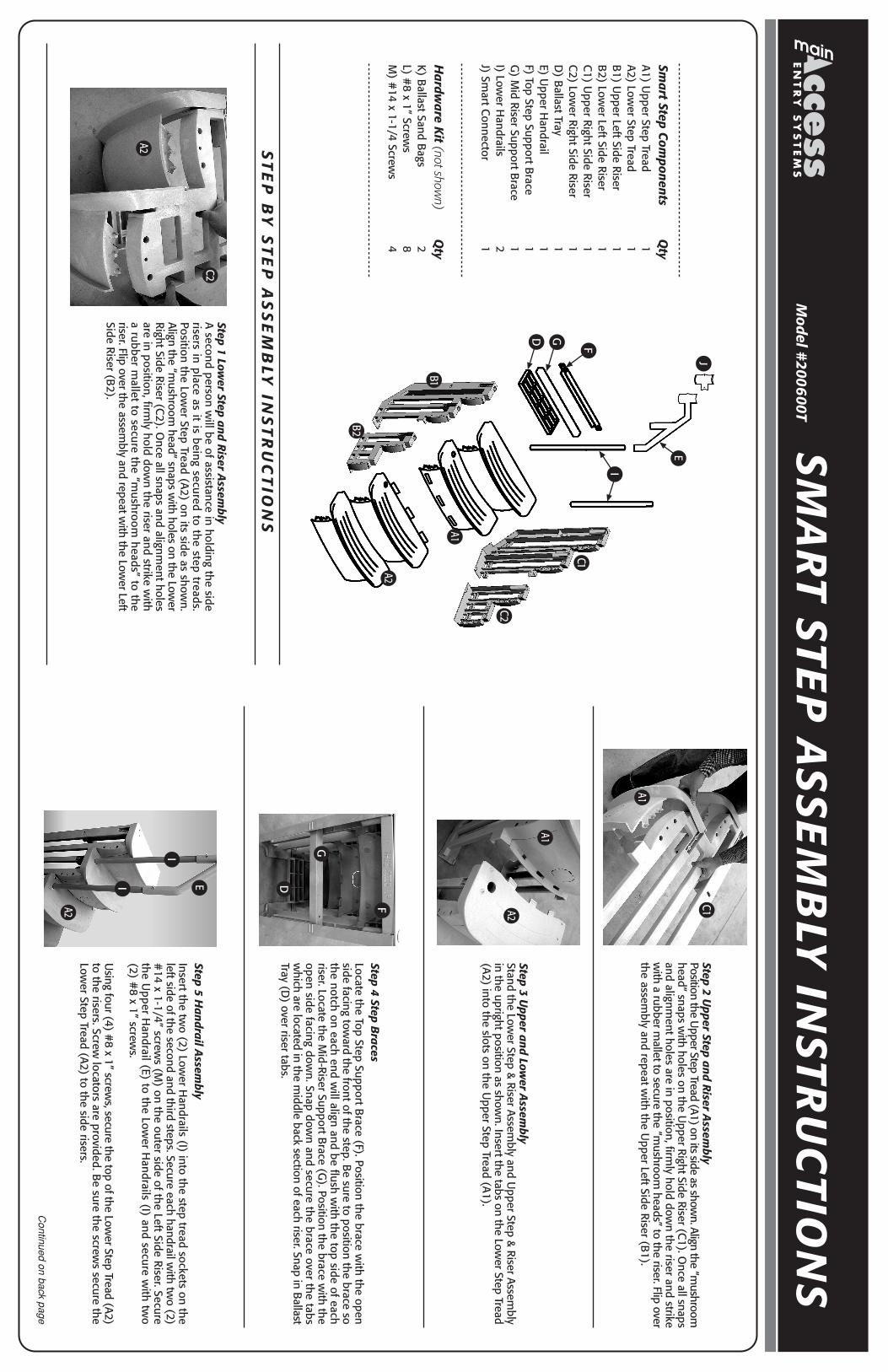
Smart Step C
omponents
Qty
A1) Upper Step Tread
1A2) Low
er Step Tread 1
B1) U
pper Left Side Riser 1
B2) Low
er Left Side Riser 1
C1) U
pper Right Side Riser 1
C2) Low
er Right Side Riser 1
D) B
allast Tray 1
E) Upper H
andrail 1
F) Top Step Support Brace
1G
) Mid Riser Support B
race 1
I) Lower H
andrails 2
J) Smart C
onnector 1
Hardw
are Kit (not show
n)Q
tyK) B
allast Sand Bags
2L) #
8 x 1” Screws
8M
) #14 x 1-1/4 Screw
s 4
SM
AR
T STEP
AS
SE
MB
LY IN
STRU
CTIO
NS
ST
EP
BY
ST
EP
AS
SE
MB
LY IN
ST
RU
CT
ION
S
Model #
2006
00T
Step 3 Upper and Low
er Assem
blyStand the Low
er Step & Riser Assembly and U
pper Step & Riser Assembly
in the upright position as shown. Insert the tabs on the Low
er Step Tread(A2) into the slots on the U
pper Step Tread (A1).
Step 4 Step Braces
Locate the Top Step Support Brace (F). Position the brace w
ith the openside facing tow
ard the front of the step. Be sure to position the brace so
the notch on each end will align and be flush w
ith the top side of eachriser. Locate the M
id-Riser Support Brace (G
). Position the brace with the
open side facing down. Snap dow
n and secure the brace over the tabsw
hich are located in the middle back section of each riser. Snap in B
allastTray (D
) over riser tabs.
Step 5 Handrail A
ssembly
Insert the two (2) Low
er Handrails (I) into the step tread sockets on the
left side of the second and third steps. Secure each handrail with tw
o (2)#
14 x 1-1/4” screws (M
) on the outer side of the Left Side Riser. Secure
the Upper H
andrail (E) to the Lower H
andrails (I) and secure with tw
o(2) #
8 x 1” screws.
Using four (4) #
8 x 1” screws, secure the top of the Low
er Step Tread (A2)to the risers. Screw
locators are provided. Be sure the screw
s secure theLow
er Step Tread (A2) to the side risers.
Continued on back page
D G
J
I
A1
A2
E
F
Step 1 Lower Step and R
iser Assem
blyA
second person will be of assistance in holding the side
risers in place as it is being secured to the step treads.Position the Low
er Step Tread (A2) on its side as show
n.Align the “m
ushroom head” snaps w
ith holes on the Lower
Right Side R
iser (C2). O
nce all snaps and alignment holes
are in position, firmly hold dow
n the riser and strike with
a rubber mallet to secure the “m
ushroom heads” to the
riser. Flip over the assembly and repeat w
ith the Lower Left
Side Riser (B2).
C1
C2
B2
C2
A2
Step 2 Upper Step and R
iser Assem
blyPosition the U
pper Step Tread (A1) on its side as shown. Align the “m
ushroomhead” snaps w
ith holes on the Upper Right Side Riser (C
1). Once all snaps
and alignment holes are in position, firm
ly hold down the riser and strike
with a rubber m
allet to secure the “mushroom
heads” to the riser. Flip overthe assem
bly and repeat with the U
pper Left Side Riser (B1).
B1
A1
C1
A1
A2
D
G
F
I
A2
EI