smart pumping system - Goulds · PDF filesignificantly reduce all major components of life ......
22
1 TITLE: DEVELOPMENT OF A SMART PUMPING SYSTEM Authors: A.E. Stavale, Sr. Project Manager, Author#1 Phone: 315-568-4021 E-Mail: [email protected] J.A. Lorenc, Sr. Research Engineer, Author #2 Phone: 315-568-7178 E-Mail: [email protected] E.P. Sabini, Director Technology, Author #3 Phone: 315-568-7523 E-Mail: [email protected] Fax (for all): 315-568-7709 Company (for all): ITT Industries, Fluid Technology Corp.-Industrial Pump Group, Seneca Falls, New York 13148 SYNOPSIS A smart pumping system was successfully developed in response to a challenge by a major chemical user to reduce the total cost of pump ownership. The system is fault tolerant and will significantly reduce all major components of life cycle cost.
Transcript of smart pumping system - Goulds · PDF filesignificantly reduce all major components of life ......

1
TITLE: DEVELOPMENT OF A SMART PUMPING SYSTEM
Authors:
A.E. Stavale, Sr. Project Manager, Author#1Phone: 315-568-4021E-Mail: [email protected]. Lorenc, Sr. Research Engineer, Author #2Phone: 315-568-7178E-Mail: [email protected]. Sabini, Director Technology, Author #3Phone: 315-568-7523E-Mail: [email protected]
Fax (for all): 315-568-7709Company (for all): ITT Industries, Fluid Technology Corp.-Industrial Pump Group,Seneca Falls, New York 13148
SYNOPSIS
A smart pumping system was successfully developed in response to a challenge by a majorchemical user to reduce the total cost of pump ownership. The system is fault tolerant and willsignificantly reduce all major components of life cycle cost.

2
DEVELOPMENT OF A SMART PUMPING SYSTEM
ABSTRACTIn today’s global economy, process plants are under constant pressure to reduce costs. Users can nolonger afford their attempts to make pumps bulletproof by upgrading component specifications. Thedevelopment of a smart pumping system was fostered by a challenge from a major chemical user toreduce the total cost of pump ownership. A smart pumping system was successfully developed that canreact and adjust itself to system changes without manual intervention.
The system is fault tolerant by virtue of the control software, which will not permit the pump to operateoutside user specified ranges, or under conditions that typically cause pumps to fail. A variable speedcontroller can match pump output to exact system head requirements, without the need for energyconsuming control valves. The smart pumping system can significantly reduce all major components oflife cycle cost.
Field-testing proceeded without incident after initial installation problems were resolved.
INTRODUCTIONTo survive in the global marketplace, process plants are under constant pressure to move liquids bothreliably and inexpensively. Today many plants have cut back on operating and maintenance personneland are often left with inexperienced people. This presents a dilemma; users can no longer afford theirattempts at making pumps bulletproof (Swalley, 1999) and the exodus of experienced personnel onlyserves to exacerbate their predicament.
As a result, a major chemical user issued a challenge to drastically reduce the total cost of pumpownership in their plants. They presented a specification for the desired performance of this “futuristic”pump, covering the following key items:
• 50,000 hour Mean Time Between Failure
• Ability to survive 10,000 start-stops
• Able to run dry
• Operating temperature range –100°F to 700°F
• Capacities to 7500 gpm, heads to 1075 ft
• Pump to be unaffected by 2 years non-operation
• Easy to decontaminate
• Operation on 50 or 60 Hz
• Standardized connections and locations
• Technical and service support as needed
• First cost 25% less than equipment replaced (pump, seal, motor, baseplate, coupling and guard)
• Rebuild cost less than 50% of new assembly
The above items can be segregated into those that can be handled by proper pump selection, materialsand construction and those that are more challenging to today’s state-of-the-art pump design. This paperwill focus on the design challenges (shown in Italics) and presents a novel approach to reducing the totalcost of pump ownership.
3
ALTERNATIVES CONSIDERED
Heavy Duty Pump
Nearly all of the design challenges identified above either directly or indirectly have an influence onincreasing the Mean Time Between Failure (MTBF) of a pump. One approach to increasing MTBF mightbe to design a heavier duty pump, one with a larger shaft and bearings, more liberal internal clearancesand thicker casing. However, clearly this approach is at odds with the requirement that the first cost be25% less than the equipment being replaced. A heavy-duty close coupled Vertical Inline (VIL) pump couldbe designed which will eliminate the cost of the pump coupling, coupling guard and baseplate. It wouldalso eliminate any maintenance costs relating to coupling mis-alignment and excessive nozzle loads dueto poor baseplate/foundation stiffness. Installation costs could also be reduced due to the elimination ofbaseplate setting and grouting work. Although this approach appears to make for a more robust pumpdesign and contributes to some reduction in initial cost, maintenance cost and installation cost, it does notaddress pump failures caused by operator error or system upsets. A pump with an extra heavy shaft andbearings will fail just as quickly as a standard pump when operating in a dry run condition or against aclosed suction or discharge valve.
The two primary causes of failures in centrifugal pumps relate to bearings and seals. There are manyreasons for failures of these components. Some are application related such as operation outsidespecified flow regimes and inadequate NPSHA. This can result in increased vibration, bearing loads,shaft deflection, recirculation damage and a poor seal chamber environment that is counterproductive tolong seal life. Other reasons relate to improper installation techniques that can cause alignment problemsdue to pipe strain and poor baseplate and foundation stiffness. Clearly, many technical articles, booksand manufacturers guidelines exist today, which promote proper pump application and installation. Yetthe norm in MTBF for chemical process pumps is only about 24 months. This is well below the MTBF forthe refining industry, which approaches 5 years (Erickson, et. al., 2000). Logic would indicate that MTBFcould be improved further by designing the pump to be more fault tolerant. Fault tolerance protects thepump from damage if it is forced outside the desired operating envelope. This protection can be achievedthrough a combination of mechanical design, materials of construction and protective devices.
Another opportunity to reduce the total cost of ownership is to minimize energy consumption. Advances inhydraulic design and computerized tools such as Computational Fluid Dynamics (CFD) have significantlyreduced the opportunities for further improvement in pump efficiency. However, many articles have beenwritten concerning the significant opportunity to reduce energy consumption with variable speedoperation. It is not unusual to achieve a 50% reduction in energy consumption and an increase in pumpreliability when using a variable frequency drive (Hovstadius, et. al., 2000). Maintenance and operatingcosts are two of the largest opportunities for reducing the total cost of pump ownership and cannot beignored. For this reason the heavy-duty pump design concept was removed from further consideration.
Computer Controlled /Artificial Intelligence Pump
A novel concept considered was to design a system rather than a pump. This system would consist of astandard centrifugal pump, a variable speed drive, instrumentation, a microprocessor and specialsoftware. There are several objectives that this system would be expected to accomplish. If a variablespeed drive is employed, operating costs could be reduced significantly by eliminating the pressure dropacross a control valve. Fault tolerance could also be built into the pumping system by developing specialsoftware that would interact with instrumentation signals that sense process conditions. The softwarewould require the ability to recognize and prevent the pump from operating under damaging conditions.Finally, if a method could be developed to use the pump casing as a flow-measuring device; in manyapplications the need for a separate flow meter would be eliminated.
The total cost of pump ownership could clearly be reduced by decreased energy and maintenance costs.Additionally, the opportunity to eliminate equipment such as a control valve, external flow meter, separatestarter and recirculation line piping could also decrease initial and installation costs. There would be

4
additional costs associated with the purchase and installation of a variable frequency drive andinstrumentation; however it was expected that the aforementioned savings could offset these costs inmany cases. It was concluded that this concept approach had merit since it worked at significantlyreducing all of the major components of the total cost of pump ownership.
VISION OF A SMART PUMPING SYSTEM
What It Should Do
A smart pumping system must be capable of knowing when to adjust itself to system changes withoutmanual intervention and must match pump output exactly to system head requirements. If upstreamconditions change due to a system transient the pump should either increase or decrease its speed inorder to maintain a constant output. A side benefit of this concept virtually eliminates the need to addsafety margins that can result in oversized pumps.
The system must be capable of recognizing and safeguarding itself from operating under conditions thatmay adversely affect its life. Conditions such as dry running, operation against a closed suction ordischarge valve and inadequate NPSH must all be recognized and reacted to before damage occurs. Thesmart pumping system must also be capable of understanding when the system transient or unusualoperating condition has cleared, thereby allowing normal pumping operation to resume.
Control modes should be flexible enough to offer system control over a wide range of applications.Control modes should be capable of maintaining constant values of speed, capacity, pressure, level,temperature or pH.
How It Should Protect
Some of the more common causes of pump failures are attributed to the following upset conditions:
• Dry running caused primarily by closed suction valves. Dry running is also common in batch andtransfer applications.
• Prolonged operation below minimum flow.
• Cavitation due to insufficient NPSH available.
• Heat build-up and subsequent liquid vaporization due to a closed discharge valve.
Smart pumping systems should be capable of detecting and reacting to all of these conditions. Thefollowing safeguards should be available to protect the pump against operating under adverse conditions.
NPSH Monitor
An NPSH margin tailored to the particular application should be specified as one of the protectiveparameters in the software. If the measured suction head drops below this margin the smart pumpingsystem can either alarm, alarm and control or alarm and fault depending on user requirements. The alarmand control mode would reduce the pump speed just enough to maintain the specified NPSH marginrequirements. However, once the transient has cleared the pump must recognize it and resume normalpumping operation.
Flow Monitor
A low flow monitor will detect a dry running condition, operation below minimum flow or against a closedsuction or discharge valve. If flow cannot be maintained, user settings can be selected to alarm, alarmand control or alarm and fault as described earlier. Magnetic drive pumps can especially benefit from thisdry run protection (Stavale, 1995). The success of power monitors and current monitors has beenmediocre at best when used for dry run protection in sealless pumps since these devices depend heavilyon proper settings by the user.

5
Other Safeguards
Other safeguards must be available to warn and protect against overpressure, overtemperature,overcurrent and overspeed. Setpoints can be selected to restrict operation to user specified ranges.
Smart pumping systems should also incorporate self-diagnostic features to compare current pumpperformance to the as new factory performance. An alarm setting will advise the user when the actualperformance degrades past a certain preset value. This will give ample warning to the user to scheduleplanned maintenance on the unit during the next outage. If a fault history and time stamp is provided itwill enable the user to accurately determine system behavior at the time of the fault. This will facilitatetroubleshooting and remedying of system upsets.
VALUE PROPOSITIONAs stated earlier the value of smart pumping systems to the user is in the reduction of the total cost ofpump ownership or total life cycle cost. Total life cycle cost encompasses the following majorcomponents:
• Operating Cost
• Maintenance Cost
• Plant Downtime and Loss of Production
• Initial Cost
• Installation Cost
• Operating Cost
• System Curves
A system curve is comprised of a static component and a dynamic component. The static component ofthe system curve does not change with flow rate. The dynamic component is essentially proportional tothe square of the rate of flow. It is also a function of other variables such as pipe configuration/size,surface roughness, quantity and type of fittings/valves and fluid viscosity. These can be represented by asingle system constant and the dynamic or frictional head can be expressed as:
Hf = K Q2
The dynamic head constant K is a constant for a given system. However, if a control valve positionchanges in the system the constant K will also change.
Conventional Systems
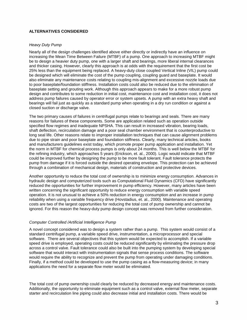
Figure 1 shows a typical control scheme for a conventional pumping system. Note the system curveincludes a static component of 6 meters (20 ft). This is the change in elevation between the suction anddischarge source. In this type of system the pump operates at a fixed speed and the pump performancecurve is based on an impeller diameter pre-selected to match the system requirements as closely aspossible. It should be noted that it is common practice to add a safety margin to the design point where itis difficult to accurately define system losses. This can result in an oversized pump that runs out too faron the curve and absorbs too much power.
6
0
10
20
30
40
50
60
0 250 500 750 1000 1250
Capacity, m3/hr
To
tal H
ead
, m B
A
The total system head curve intersects the pump head-capacity curve at point “A” with the control valvewide open. The design flow for this system is about 640 m3/hr (2800 gpm) so the friction head (point “B”)must be increased to about 37 meters (120 ft) in order to operate at this point. The most commonmethod of varying the capacity in a conventional system is to introduce a variable resistance device thatwill alter the system friction curve; this is the main function of a control valve. Control valves are throttlingdevices, which use some of the available pumping energy to control the process. The amount ofconsumed energy will vary depending on the method of control, valve sizing and the operating point. Inthe U.S., a common control valve standard (PIP PCECV001) specifies that the control valve shall be 50-80% open at design flow, at least 10% open at minimum flow and no more than 90% open at maximumflow. Other methods base the amount of pressure drop on past plant practice or rules of thumb.
Variable Speed Systems
In a variable speed system the controller will match the pump output to system head requirements withoutthe need for a control valve. Safety factors and pressure margins typically built into dynamic headsystems can be eliminated and in some cases result in a lower cost pump selection. Since the smartpumping system can adjust the pump speed to suit the required system conditions only one impellerdiameter need be stocked. This offers the benefit of lower inventory cost. In variable speed systems thedesign point no longer needs to be based on a fixed speed. This yields a larger number of selections overa given pump range with a better chance of operating at or near the best efficiency flow. Variable speedcontrol is most effective and efficient in all friction head systems. The effectiveness diminishes somewhatfor applications having high static head and low dynamic head, since the intersection of the pump andsystem curve moves further to the left of the best efficiency flow (Casada, 1999). Careful selection isrequired for these applications to avoid operation below minimum allowable flow and possibledeadheading.
Figure 2 shows a variable speed system with system curve “A” identical to that shown in Figure 1. Head-Capacity curves are shown at various speeds. If the desired operating flow is 640 m3/hr (2800 gpm) it isshown that the pump can operate at a substantially lower speed and head. In this example, the savings ofthe variable speed system over a conventional system is represented by the difference in head betweenpoints “B”(Figure 1) and “C” (Figure 2). This difference in system head requirements can often translate tothousands of dollars in annual energy savings over the life of a pump.
Figure 1. Conventional Pumping System Control.

7
0
10
20
30
40
50
60
0 250 500 750 1000 1250
Capacity, m3/hr
To
tal H
ead
, m
C
A
.83 N
.9N
.7N.6N
1.0N
Maintenance Cost
As mentioned earlier, the primary components in pump failures are bearings and mechanical seals.Excessive vibration, excessive loads and/or poor lubrication are the primary causes of failure for theseparts. Designing a pump with a larger shaft and bearings may appear to be more robust but does notguarantee longer life. Many failures can be attributed to operator error and application factors. Operatingrange, impeller diameter, operating speed and protection against system upsets all have an effect on theoverall reliability of a pump.
Operating Range
A centrifugal pump is designed to operate most reliably at one capacity for a given speed and impellerdiameter. This capacity is usually at or near the best efficiency flow. As pump operation moves away fromthis optimum capacity, turbulence in the casing and impeller increases. As a result hydraulic loads, whichare transmitted to the shaft and bearings, increase and become unsteady. These loads are related to theimpeller diameter in a cubic manner. The severity of these loads can have a negative effect on reliability.
Impeller Diameter
Impeller diameter affects reliability by the loads that are imposed to the shaft and bearings as the impellervanes interact with the volute cutwater. These loads are also related to the impeller diameter in a cubicmanner. Maximum or near maximum impeller diameters result in a less than optimum gap between thecutwater and impeller. As each vane passes the cutwater a large pulse is produced which results in anaccompanying unsteady deflection of the pump shaft. These unsteady deflections can be very damagingto mechanical seals. There is an optimum cutwater gap that will limit these unsteady deflections. Withlarger than optimum gaps the damaging cutwater effect is minimized but the effects of suction anddischarge recirculation become of more concern, especially if vane overlap is lost due to large impellertrims.
Operating Speed
Operating speed affects pump reliability through rubbing contact and wear in seal faces, reduced bearinglife due to increased loads, lubricant breakdown due to excessive heat and wetted component wear dueto abrasives in the pumpage.
In addition, an increased operating speed can easily push a low suction energy pump into a high suctionenergy region (Budris, 1993) with accompanying noise, vibration and possible cavitation damage. Theonset of high suction energy levels in pumps is directly related to operating speed, suction specific speed,
Figure 2. Variable Speed Pumping Control.

8
specific gravity and the thermodynamic properties of the liquid being pumped, as well as impellergeometry and operating point.
Quantification of Reliability Improvements
The protection that smart pumping systems offer will no doubt translate to extended meantime betweenfailure and improved life cycle maintenance cost. One method of quantitatively predicting these life cyclecost savings is outlined by Bloch and Geitner (1994). In this method, reliability factors for operatingspeed, operating point and impeller diameter are assigned values between 0 –1, where higher valuesindicate more reliable selections. A reliability index, which is the product of the three reliability factors, canthen be compared to pumps of similar design to give an indication of overall reliability. Note this method isonly valid for comparing pumps of similar design since it does not take design characteristics intoconsideration. An independent test program generally confirmed the validity of these published reliabilityfactors and offers recommendations for improvement (Erickson, et. al., 2000).
Plant Downtime and Loss of Production
Even a properly selected pump with materials of construction suitable for the application is no guaranteeof long life. As described earlier, smart pumping systems must also be fault tolerant. This protects thepump against operator abuse, improper startup, operation in damaging flow regimes, dry running,inadequate NPSH, overpressurization, overtemperature, overtorque, overspeed and underspeed. Theseupsets often result in unplanned premature equipment failure with consequential plant downtime and lossof production.
It should be noted that the added protection that fault tolerance provides is not quantified in the Bloch andGeitner (1994) method.
Initial Cost
Initial cost is the smallest of the life cycle cost components but usually receives the greatest focus duringthe procurement cycle. Many users become pre-dispositioned at the sound of the words “smart pumpingsystem” and “variable speed controller” when they think of cost. However, if the total initial cost of a smartpumping system is compared to that of a conventional system it can be shown that smart systems can bevery competitive in price. When compared to total life cycle cost, these systems can have anoverwhelming advantage.
As mentioned earlier in this paper, smart pumping systems continuously monitor both pump and systemconditions and match pump output to system requirements, exactly. Since the smart controller is avariable speed device there is often no need for an automatic control valve in the system. Onemanufacturer has a patented method of measuring process flow internal to the pump discharge nozzle. Inmany applications this could eliminate the need for a separate external flowmeter in the system.Additionally, smart controllers have integral starters thereby eliminating the need for a separate starter.
One of the many safeguards built-in to smart controllers is to protect against operation below minimumflow. Operation can be restricted to user specified ranges. Depending on system design, recirculationlines and valves can also be eliminated. Since added safety margins are not required when controllingwith a variable speed system, in some cases a smaller pump can be used. The added fault protection andsafeguards may also eliminate redundant systems in some applications.

9
Installation Cost
By reducing the amount of equipment in a system both installation and maintenance costs are decreased.The installation costs associated with piping, air lines, wiring and communication lines can all bedecreased by eliminating a control valve, flowmeter, separate starter and recirculation line valve andpiping.
PROTOTYPE EVALUATIONSEarly concept approaches were required to help define what the product should be. Three separateconcepts were evaluated:
• The Proof of Concept (POC) unit utilized a laptop PC communicating with a 10-channel dataacquisition system and a 1 hp 230 VAC commercially available VFD.
• A Black Box (BB) unit that incorporated a custom 8 input channel / 2 output channel PC board havingbasic computing capability similar to a programmable logic controller (PLC). A 10 hp 460 VACcommercially available VFD was also used.
• A 5 input channel/2 output channel custom programmed Smart VFD (3 hp 460VAC).
Proof of Concept
The POC was connected to a one-half scale model end suction pump. The centrifugal pump wasmounted on a rigid baseplate and coupled to a .86 kW 3420 RPM, 230VAC electric motor. The VFDcontrolled the speed of the motor. The baseplate was mounted on a portable bench. The pump waspiped to a 15-gallon clear cast acrylic tank with clear acrylic tubing as shown in Figure 3. A hand-operated ball valve was installed at the pump discharge to artificially change system friction. Anadditional hand-operated valve was piped to the pump suction to vary the NPSHA.
The Proof of Concept unit focused on pump sensing, pump control/management, fault tolerance andcondition monitoring. The unit logged the following data:
Figure 3. Proof of Concept Model.

10
• Differential Pressure measured across the casing throat and the discharge flange. (psid)
• Discharge Pressure. (psia)
• Suction Pressure. (psia)
• Fluid Temperature (OF)
• Pump Speed (RPM)
• Mechanical Seal Face Temperature. (OF)
• Seal Chamber Temperature. (OF)
• Outboard Bearing Vertical Vibration. (in/sec)
• Bearing Housing Oil Temperature. (OF)
• Water Concentration in Bearing Housing. (PPM)
The model pump was tested for Head, BHP, NPSHR and differential pressure (dP) vs. Capacity at fourdifferent speeds (3600, 2800, 2000, and 1200 RPM). The dP was measured across the casing throatand discharge flange and was used along with speed and fluid temperature (sp. gr.) to characterize flowover the entire operating range of the pump. Subsequent testing showed that the flow accuracy for thisunit was within • 1% for operation between 40 and 115 percent of BEP and better than 5% over the entireoperating range (0 to 140% of BEP).
The pump curves, flow characterization and fluid properties were loaded to a Quick Basic (QB4.5)program. These curves established a baseline to which the pump performance could be compared. Acustom control algorithm was developed to control flow and pressure. This eliminated the need forproportional-integral-derivative (PID) loops in the program. This algorithm was originally developed tocontrol a pump with a flat or drooping head-capacity curve operating against a flat system curve. ThePOC controlled constant flow or pressure under any induced system friction changes. The QB4.5program acquired data and updated the VFD at rates ranging from 1 to 2 Hertz.
Once control was established the program compared the head that the pump was producing at a givenflow and speed to its baseline value. An alarm “Renew Clearances” was programmed to warn of a 10percent loss in head.
Transients caused by quickly opening and closing valves resulted in pump system instabilities because ofthe slow 1 to 2 Hertz update rate. The update rate was limited by the speed of the PC and the 10-channel data acquisition system
Any VFD can control a pump to maintain constant flow, pressure etc. What would differentiate thispumping system from any other is its fault tolerance. The unit was programmed to react to the mostcommon causes of system induced pump failure. The unit constantly monitors and calculates flow andNPSHA and compares these values to the baseline NPSHR. The program incorporated a 3-foot NPSHAmargin above the pump NPSHR to trigger an alarm. The pump was programmed to slow down justenough to maintain the required 3-foot margin. Once the condition corrected itself the pumpautomatically resumed operation at the proper set point. The unit was also programmed to alarm and/orreact to a low flow, a closed suction valve or closed discharge valve condition. The pump will react tothese faults by slowing down to a predetermined speed where damage will not occur. Again once thecondition corrected itself the pump automatically resumed operation at the proper set point. The unit wasalso programmed to shut down automatically on over-pressure or over-temperature condition (safetyrelated).
The POC unit also logged, alarmed and reacted to a variety of condition monitoring sensors. The unittrended bearing lubricant temperature and overall vibration. An abrupt change in vibration or temperaturefor a given set point would trigger an alarm.

11
Seal chamber pressure and seal face temperature was also monitored. An increase in seal facetemperature would result in a corresponding increase in the vapor pressure of the fluid. If the vaporpressure exceeds the seal chamber pressure, fluid flashing at the seal faces would occur with potentialseal damage. A protective alarm/fault was programmed in the software for this condition. This fault couldoccur when the pump is cavitating, running dry, or operating below its recommend minimum thermal flow.It should be noted that the program and controller reacted within one to two seconds to all induced faults;as a result we were unable to induce bearing or seal problems.
Water concentration in the oil was also constantly monitored. The unit was set to trigger an alarm withwater concentrations greater than 180 PPM (ISO 68 oil).
Black Box
The QB4.5 program used on the POC was rewritten in C++ and down loaded to the BB unit. Thecondition-monitoring portion of the program was not incorporated due to I/O limitations.
The original BB program did not contain the custom flow/pressure control algorithm. Instead control wascarried out using standard PID loops. These loops at best were not as stable as the custom algorithmand in need of constant tuning as the system parameters changed. The program was then updated tothe control algorithm.
This unit had an update rate of 3 to 4 Hertz and performed very similarly to the POC. Consequently itexperienced the same instability problems as the POC due to quick opening and closing of valves.
Smart VFD
The program was rewritten in assembly language and loaded onto the Smart VFD. It was decided thatcondition monitoring would be made available later as an optional add-on to the system. The concept ofthe smart pumping system was to protectively react to a fault and greatly reduce the risk of pump failure.Condition monitoring should be available for users who choose not to react to a fault protectively. It wouldalso be useful in detecting non-system-induced faults; e.g., poor alignment or excessive piping loads.
Transients did not effect operation. The drive reacted to all system induced faults in a very stablemanner. Extensive fault testing was carried out with no mechanical seal or bearing problemsencountered.
The unit met its desired goals of sensing, managing and controlling the pump. This unit helped define thefinal product specification.
TEST VALIDATION: CHALLENGES AND PROBLEMS
Response Time
A poorly designed automatic control system will exhibit overshoot, undershoot or porpoising (oscillation)about the setpoint. In a proportional controller the output signal is proportional to the difference betweenthe setpoint and actual conditions. The gain adjustment is an inverse function of the controllerproportional band. Figure 4 shows a typical system response curve to a sudden change in load with lowgain adjustment (wide proportional band) i.e., the system response to the error signal is small. Figure 5shows a typical system response curve to a sudden change in load where porpoising occurs. This systemhas a high gain adjustment (narrow proportional band) i.e., the system response to the error signal ishigh. Note in systems with proportional action only there is always some residual offset (Wachstetter,1994). Testing of the initial POC and BB concept designs previously described had many of theseproblems even when PID loop controllers were used.

12
Time
Pro
cess
Var
iab
le
Narrow P roportional Band
S etpointOffset
Figure 5. Proportional Control with Porpoising.
Time
Pro
cess
Var
iab
le
Wide Proportional Band
Setpoint
Offset
Figure 4. Proportional Control with Offset

13
It wasn’t until the VFD based smart pump concept was developed that a successful optimization of thepump hydraulic response characteristics, the motor dynamic response characteristics and the VFDresponse was achieved. This optimization was partially attributed to an increased update rate of processsignals that the VFD offered when compared to the initial prototypes. The stability was madeindependent of the system that the pump was operating in by developing proprietary control algorithms.Figure 6 shows the typical system response possible when using the proprietary control algorithmcoupled with an increased update rate of the process signals. It should be noted that major changes orupsets in a pumping system that could cause a PID loop controller to become unstable and necessitatere-tuning would not affect the algorithm-based control.
Ground Fault Loops
Ground loops presented another challenge. Whenever there is three phase power present (motor voltageand current) along with 4-20 milliamp (mA) instrument signals there exists the potential for ground loops.This is especially true for voltages generated using Pulse Width Modulation (PWM) variable speed drives.The first ground loop problem occurred with metal diaphragm pressure transmitters that exhibited erraticsignals but only when the VFD was delivering electrical power to the motor. Even though the cablingfrom the VFD to the motor was grounded per manufacturer’s recommendations, the high switchingfrequency of the VFD would create a voltage potential in the motor/baseplate/pump. This high frequencyvoltage potential would return to the variable frequency drive not only through the motor power leadground but also through the metal diaphragm pressure transmitters. It was found that the EMI capacitorin the transmitter was acting as a short circuit at the high switching frequency thereby allowing the voltageto modulate the 4 –20 mA signal. This was resolved by switching to a different transmitter design.
A second ground loop problem occurred when the smart system was applied to an end user that had anuclear level indicator. Despite the fact that the cables from the VFD to the motor were routed throughsolid wall conduit connected at both the motor and VFD, a high frequency voltage potential was detectedin the conduit which was sufficient to disrupt the 0-1 mA DC signal from the level indicator. Groundingstraps or bars welded across each conduit coupling and at the motor and VFD were recommended. Thiseliminated the insulation effects of the pipe sealant and created a better path to ground for the highfrequency voltage potential generated in the conduit.
Time
Pro
cess
Var
iab
le
Algorithm Control
Setpoint
Figure 6. System Response with Algorithm Control.

14
Flow Accuracy
As part of the objective of reducing total life cycle cost, a method was developed to measure flow directlyin the pump discharge nozzle. The pump casing is calibrated by relating flow to differential pressure androtational speed. As the nozzle area changes from the casing throat to the discharge outlet a differentialpressure is produced similar to a venturi effect. Figure 7 shows a typical dP Vs flow curve at severalspeeds for an ASME B73 3x4-13 pump.
As expected it was found that the amount of differential pressure available varied by nozzle design andwas also influenced by casting variations. Casting variations between different metallurgies necessitatedthat each pump casing be calibrated in order to assure flow accuracy. This concept in flow measurementis similar in limitation to other differential pressure (dP) measuring devices. These devices have a flowaccuracy of 2-5% depending on size, a rangeability of 3:1 and are limited to clean liquids. As with otherdP measuring devices field accuracy was dependent on good piping practice immediately downstream ofthe casing discharge nozzle.
Stable Algorithms for High Static Head Systems
A real concern with applications involving variable speed pumping in high static head systems is that areduction in pump speed may cause the pump to operate in a deadhead condition. In high static headsystems as the pump speed decreases, the intersection point between the pump and system curvemoves further to the left of the best efficiency point. If the pump speed is reduced far enough where thepump total head falls below the system static head, a zero flow condition will result. This can result inoverheating, liquid vaporization and a possible explosive condition.
The smart system was designed so that there are two user-defined parameters that preclude deadheadoperation. The first parameter is the minimum speed of the pump. This parameter is selected such thatthe pump generated total dynamic head (TDH) is always greater than the static lift in the system. Thisinsures that even if the pump is operated at the minimum speed there is sufficient pump TDH generatedto produce flow through the system. The second parameter defines the minimum flow of the pump at themaximum operating speed. This parameter is used to calculate the minimum continuous flow for thepump at all other speeds. If the flow at any pump speed falls below the minimum flow calculated for thatspeed an alarm and/or fault condition will occur to alert the end user that the pump is operating in apotentially damaging situation.
ASME B73 3x4-13Typical dP vs Flow
0
10
20
30
40
0 500 1000 1500
Capacity, US GPM
Dif
fere
nti
al H
ead
, FT
W
ater
1800 rpm
1500 rpm
1200 rpm
800 rpm
Figure 7. Typical Curve—Differential Pressure Versus Flow
15
FINAL DESIGN CONCEPT
Major Components
The final design concept for the smart pumping system consisted of a standard centrifugal pump,standard variable speed controller, instrumentation, microprocessor and special control software. Theinstrumentation includes an absolute suction pressure transmitter, suction temperature transmitter andsensor, absolute discharge pressure transmitter and a differential pressure transmitter (required only ifflow is measured in the pump casing). If an external flowmeter is used, an analog signal must be providedto the microprocessor in order to measure flow. The instrumentation senses process conditions andtransmits 4-20 mA signals to the microprocessor. There are five analog inputs and two analog outputsignals available which are set-up for 4-20 mA (24 VDC power required). There are also six digital inputsand three digital outputs available. Control is available by using either analog or digital inputs. The controlalgorithm developed in-house was used for capacity and pressure control due to its superiorperformance.
The microprocessor resides in the variable speed controller. It stores the pump control software thatenables the controller to sense pump and process conditions and react accordingly. The system isdesigned to maintain constant values of speed, capacity, pressure or level and can be controlled by alocal keypad, hard-wired control or through a distributive control system (DCS). The following fieldbusadapters support communication with the DCS: CS-31, Devicenet, Interbus-S, Modbus, Modbus Plus andProfibus.
Application Specific Data
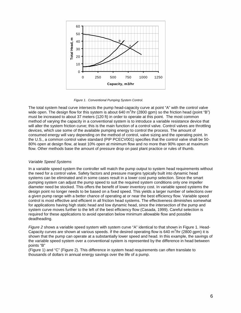
Each pump is hydraulically characterized at the factory to identify the entire pump performance envelopeincluding NPSHR. Fluid characteristics such as specific gravity and vapor pressure are also identifiedover the entire temperature range of the liquid being pumped. Next, the pump manufacturer and userjointly identify the control parameters and alarm/fault settings desired for the application. Table 1 shows apartial listing of the control parameters and alarm/fault settings required.
Table 1. Typical Control Parameters and Alarm / Fault Settings.
Control Parameter Alarm/Fault SettingsLocal or Remote Control TDH Alarm Level
Maximum/Minimum Speed NPSH Monitor
Maximum/Minimum Flow Flow Monitor
Maximum/Minimum Pressure Pressure Monitor
Specific Gravity Constants Pressure Alarm Value
Vapor Pressure Constants Pressure Fault Value
Max. Signal Feedback NPSH Control Time
Control Method Flow Control Time
Suction/Discharge Diameter Pump Shutoff Temperature
All of the pump hydraulic data and fluid characteristics are then processed through a test utility thatcalculates the polynomial curve fit coefficients. The utility also gathers and formats user-definedparameters, control settings and alarm/fault values which are used in the control software. To completethe process the control software and all application related data are downloaded to the microprocessorvia fiber optic cables.

16
FIELD TESTING
Installation
The first unit was installed on a cooling tower service for a hydrogen purification plant (Kratowicz, 2000).The plant runs automatically and is unattended. The pump that was provided is an ASME B73 8x10-13pump driven by a 100 HP 1780-rpm motor. The installation consisted of two pumps, one main and aninstalled spare. Each of two units are sized to supply approximately 2800 gpm at 120 ft total dischargehead to the cooling water header serving the plant. Although it was intended that both pumps be installedas smart-pumping units, initial problems with the installation and setup resulted in only one of the unitsbeing configured in this manner. The backup unit was configured as a conventional fixed speed pump.
Startup
The pump was started in speed mode and operated near full speed (1780 rpm) with the pump dischargethrottle valve set at about 55% open. Once the system was stabilized the unit was placed in pressurecontrol mode with the setpoint equal to the pressure developed at full speed with the valve at 55% open.The setpoint was reduced in steps by increasing the amount of valve open until the desired downstreampressure was achieved with the discharge valve wide open. This resulted in a speed reduction of over300-rpm and a corresponding power reduction of about 40 hp when compared to the installed spare thatwas operated in a conventional system.
Operating Experience
The unit has been in unattended operation for nearly 9,000 hrs. During this period there have been noreported alarms, faults or other problems to date. The calculated energy savings based on 9000 hrsoperation for the smart pumping system in this application is $15,500. The primary goal of the user in thisapplication was to prove out the reliability of the system before moving into a more aggressiveapplication. To this end the user is reported to be very satisfied with the performance of the system.

17
LIFE CYCLE COST EVALUATION
Operating Cost Savings
The following life cycle cost evaluation (Stavale, 2000) is based on the cooling tower installationdescribed in the field test section. Figures 1 and 2 illustrate the savings of a variable speed system over aconventional system for this installation. This is shown as the difference in head between points “B”(Figure 1) and “C” (Figure 2) and is exemplified in Table 2.
Table 2. Life-Cycle Operating Cost Savings.
ConventionalSystem
Smart PumpingSystem
Pump Size 8x10-13 (ANSI B73) 8x10-13 (ANSI B73)
Rating at design, m3/hr (gpm) 639 (2800) 639 (2800)
Rating at design, Total Head, m (ft) 37 (120) 23 (75)
Speed, r/min 1780 1476
Yearly Operation, hrs 8760 8760
Rating at Design, kW (Bhp) 77.3 (104) 47.7 (64)
Equipment Life, Years 15 15
Yearly Energy Use, kW-hr 707,700* 456,400**
Total Energy Use, kW -hr 10,615,000* 6,845,000**
Electricity Cost, $(US) 0.06 0.06
Total Life Cycle Operating Cost, $(US) 636,900* 410,700**
Life Cycle Operating Cost Savings: $(US) 226,200 * Includes motor losses ** Includes motor and VFD losses
Note that the total pump head has been reduced from 37 meters (120 ft) to 23 meters (75 ft). As aresult the pump power has dropped nearly 30kW (40 hp) and operating speed has been lowered by over300 rpm.
Maintenance Cost Savings
Table 3 shows the effect on life cycle maintenance savings for the cooling tower application using theBloch and Geitner method described previously. It assumes an average MTBF for a conventional sealedpump of 18 months at an average cost per repair of $(US) 2,500. Note the saving shown should beconsidered to be conservative since the Bloch and Geitner (1994) method does not take into accountpotential savings due to fault tolerance.
Table 3. Life-Cycle Pump Maintenance Cost Savings.
ConventionalSystem
Smart PumpingSystem
Reliability Index 0.2 0.3
Average MTBF, Months 18 27.1
Equipment Life, Years 15 15
Total No. of Repairs 10 6.6
Total Pump Maintenance Cost (US) 25,000 16,600
Life Cycle Pump Maintenance Cost Savings: $(US) 8,400

18
The difference in pump life cycle maintenance savings for this application represents a 33.5% decreasewhen compared to a conventional system and MTBF is extended from 18 to 27 months.
Initial Cost Savings
Figure 8 shows a conventional system with pump/motor, control valve, flowmeter, isolation valves,recirculation line, DCS and starter. Smart pumping systems integrate the functionality of several of thesepieces of equipment as shown in Figure 9.
Figure 8. Conventional Pump Systems.
Figure 9. Smart Pumping System.
19
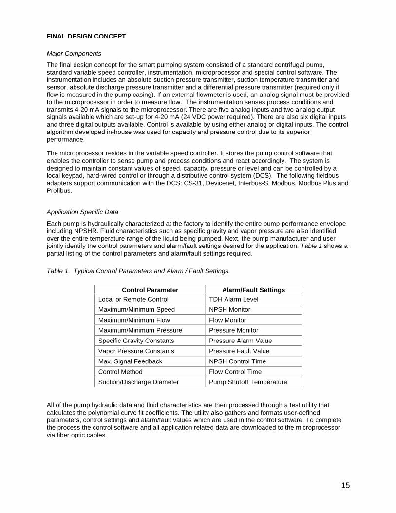
Table 4 shows that the life cycle initial cost savings for this cooling tower application compares favorablywith a conventional system.
Table 4. Life-Cycle Initial Cost Savings.
ConventionalSystem, (US)
Smart PumpingSystem, $(US)
Pump, baseplate, coupling and motor 10,600 10,000
Smart Controller and Instrumentation 0 9,800
Control Valve 4,700 0
Flowmeter 4,300 0
Recirculation Line 0 0
Motor Starter 1,000 0
Total Life Cycle Initial Cost, $(US) 20,600 19,800
Life Cycle Initial Cost Savings: $(US) 800
Installation Cost Savings
Table 5 shows the effect on life cycle installation savings for the cooling tower installation. In this examplepump installation costs are based on 5x initial cost. Installation costs for the control valve, flowmeter andstarter are based on 3x initial cost of these components.
Table 5. Life-Cycle Installation Cost Savings.
Conventional System$(US)
Smart PumpingSystem $(US)
Pump, baseplate, coupling and motor 53,000 50,000
Smart Controller and Instrumentation 0 3,750
Control Valve 14,100 0
Flowmeter 12,900 0
Recirculation Line 0 0
Motor Starter 3,000 0
Total Life Cycle Installation Cost, $(US) 83,000 53,750
Life Cycle Installation Cost Savings: $(US) 29,250
The difference in pump installation savings for this application represents a 35% decrease as comparedto a conventional system.
Since the control valve and external flowmeter have been removed from the smart pumping system,maintenance for these items can also be eliminated as shown in Table 6.
Table 6. Life-Cycle Other Maintenance Cost Savings.
Conventional System$(US)
Smart Pumping System$(US)
Smart Controller and Instrumentation 0 2,000
Control Valve 3,200 0
Flowmeter 2,800 0
Total Life Cycle Installation Cost,$(US)
6,000 2,000
Life Cycle Other Maintenance Cost Savings: $(US) 4,000

20
Total Life Cycle Cost Savings
A summary for each of the major life cycle cost components is shown in Table 7 for a conventional andsmart pumping system for the cooling tower installation.
Table 7. Life-Cycle Cost Summary
Conventional System$(US)
Smart Pumping System$(US)
Life Cycle Operating Cost 636,900 410,700
Life Cycle Pump Maintenance Cost 25,000 16,600
Life Cycle Other Maintenance Cost 6,000 2,000
Life Cycle Initial Cost 20,600 19,800
Life Cycle Installation Cost 83,000 53,750
Total Life Cycle Cost 771,500 502,850
Total Life Cycle Cost Savings: $(US) 268,650
The total life cycle savings for this installation is $(US) 268,650. This represents a 35% saving over afifteen-year equipment life. The present value of these savings, assuming a 10% interest rate, is$148,300 and the difference in initial capital investment is negligible.
CONCLUSIONSA smart pumping system has been successfully designed that can react and adjust to system changeswithout manual intervention. The system is capable of recognizing and safeguarding itself from operatingunder conditions that may adversely affect its life. This fault tolerant design has the ability to protect itselffrom operating under conditions such as dry running, operation against a closed suction or dischargevalve, operation below minimum allowable flow and cavitation due to insufficient NPSH available. Thesystem has the ability to recognize when the adverse operating condition has passed and will resumenormal pumping operation when it is safe to do so. Field-testing proceeded without incident after initialinstallation problems were resolved.
The system can significantly reduce all major components of life cycle cost. A variable speed controller isable to match pump output to system head requirements exactly without the need for an energyconsuming control valve. This can reduce operating costs significantly over the life of the pump. Thecontrol software will not permit the pump to operate outside user specified ranges or under conditions thattypically cause pumps to fail. As a result maintenance costs will decrease and MTBF will increase forthese systems. When comparing the cost of smart-pumping systems to conventionally operated systemsall aspects of total life cycle cost should be evaluated.
FUTURE SYSTEMSThe advent of smart pumping technologies for the first time gives the plant the ability to use the pump as:
• An asset sensing device
• An asset maintenance device
• A process controlling device.
Plants finally have the ability to mine the data obtained from these devices and use this information tooptimize entire operations.
The technology is available to automatically write work orders, obtain parts from stock or place partsorders (as required) once a fault is encountered. Plant personnel will be notified of the problem and givencopies of the work order, pertinent drawings and installation manual.

21
Future systems will incorporate:
• Condition Monitoring capabilities.
• MicroElectroMechanical Systems (MEMS) miniature sensors will be built into pumps and motors.Artificial intelligence and neural networks will be used to validate sensor readings. If a sensor fault isdetected a virtual sensor will be substituted until the faulty sensor can be replaced.
• Wireless communications of data will become common place.
• Cascaded loop control programs will be part of every drive.
The current trend is to have the control function move from the large centralized distributed controlsystem (DCS) to the appliance level at the plant floor.

22
REFERENCESBloch, H.P. and Geitner, F.K., 1994, “An Introduction to Machinery Reliability Assessment”, SecondEdition, Gulf Publishing Co., Houston, Texas.
Budris, A.R., 1993, “The Shortcomings of Using Pump Suction Specific Speed Alone to Avoid SuctionRecirculation Problems”, Proceedings of the Tenth International Pump Users Symposium,Turbomachinery Laboratory, Texas A&M University, pp. 91-95.
Casada, D., 1999, “Energy and Reliability Considerations for Adjustable Speed Driven Pumps”, IndustrialEnergy Technology Conference, Houston, TX, pp. 53-62.
Erickson R.B., Sabini E.P. and Stavale A.E., Hydraulic Selection to Minimize the Unscheduled Portion ofLife Cycle Cost", Pump Users International Forum 2000, Karlsruhe, Germany.
Hovstadius G., Erickson R.B. and Tutterow V., 2000, Pumping System Life Cycle Costs, An OverlookedOpportunity?, PumpLines pp.10-12.
Kratowicz, R., 2000, “Less is More”, Fluid Handling Systems Magazine, pp.30-33.
Stavale, A.E., 1995, “Dry Running Tests Utilizing Silicon Carbide Bearings and Polymer Lubricating Stripswith Conductive and Nonconductive Containment Shells in an ANSI Magnetic Drive Pump”, Proceedingsof the Twelfth International Pump Users Symposium, Turbomachinery Laboratory, Texas A&M University,pp. 77-82.
Stavale, A.E., 2000,"Smart Pumping Systems: The Time is Now", Proceedings of PACWEST 2000Jasper Conference, Pulp and Paper Technical Association of Canada.
Swalley, J.C., 1999, "Bomb-Proof or Best Value", Pumping Technology Magazine, pp. 24-25.
Wachstetter, J., 1994, "Understanding the Principal Control Actions of Single-Loop and MultiloopControllers", I&CS Magazine, pp. 45-51.