
Smart Grid Integration of Hybrid Energy System with Regulated Voltage using Cockcroft & Sepic...
14
IJIRST –International Journal for Innovative Research in Science & Technology| Volume 3 | Issue 02 | July 2016 ISSN (online): 2349-6010 All rights reserved by www.ijirst.org 42 Smart Grid Integration of Hybrid Energy System with Regulated Voltage using Cockcroft & Sepic Converters B. Krishnapriya Krishna Mohan Das Assistant Professor PG Scholar Krupajal Engineering College, Bhubaneswar, India1 SRM University, Chennai, India Abstract Smart grids will provide more electricity to meet rising demand, increase reliability and quality of power supplies, increase energy efficiency, is able to integrate low carbon energy sources into power networks. This paper deals with the development and control of a smart grid-connected PV/WT hybrid system model. This model consists of wind turbine, photovoltaic array, asynchronous (induction) generator, controllers and converters (Sepic & Cockcroft). It is developed by using MATLAB/SIMULINK software package. In order to maximize the generated power, Cockcroft & Sepic convertors are used. Under various operating conditions, the dynamic behavior of the proposed model is examined. The inputs given to the developed system are the real-time measured parameters. The wind speed, solar irradiance and temperature data are collected from a grid connected solar power system located in Manchester. The control strategy of the proposed model results a better tool for smart grid performance optimization. Keywords: Control systems, Hybrid power systems, MATLAB, Modeling, Photovoltaic systems, Power electronic Converters, Smart grids, Wind power generation _______________________________________________________________________________________________________ I. INTRODUCTION THE limitations of global resources of fossil and nuclear fuel, has necessitated an urgent search for alternative sources of energy. Therefore, a new way has to be found to balance the supply and demand without resorting to coal and gas fuelled generators. Smart grid is a system that would enable the integration of renewable energy sources and shift from reliance on fossil fuels, while maintaining the balance between supply and demand. The key characteristics of smart grid include: System reliability and operational efficiency (Grid optimization) Distributed generation: not only traditional large power stations, but also individual PV panels, micro-wind, etc. Advanced metering infrastructure Demand response. Grid-scale storage. This paper focuses mainly on the smart grid integration of PV/WT hybrid system (grid optimization and distribution generation). In this study, a detailed dynamic model, control and simulation of a smart grid-connected PV/WT hybrid power generation system is proposed. Modeling and simulation are implemented using MATLAB/SIMULINK software package to verify the effectiveness of the proposed system. II. SYSTEM DESCRIPTION AND MODELING Smart grid is a system comprises of three layers: power layer, control layer and application layer. Smart grid has to be dynamic and have constant two-way communication, as shown in Fig.1. Thus, for example, with PV panels on the roofs, intelligent building system will generates, store and use their own energy. Hence, as active buildings they become part of the smart grid. This could save energy and enhance reliability and transparency.
-
Upload
ijirst-publication-house -
Category
Education
-
view
22 -
download
0
Transcript of Smart Grid Integration of Hybrid Energy System with Regulated Voltage using Cockcroft & Sepic...

IJIRST –International Journal for Innovative Research in Science & Technology| Volume 3 | Issue 02 | July 2016 ISSN (online): 2349-6010
All rights reserved by www.ijirst.org 42
Smart Grid Integration of Hybrid Energy System
with Regulated Voltage using Cockcroft & Sepic
Converters
B. Krishnapriya Krishna Mohan Das
Assistant Professor PG Scholar
Krupajal Engineering College, Bhubaneswar, India1 SRM University, Chennai, India
Abstract
Smart grids will provide more electricity to meet rising demand, increase reliability and quality of power supplies, increase
energy efficiency, is able to integrate low carbon energy sources into power networks. This paper deals with the development
and control of a smart grid-connected PV/WT hybrid system model. This model consists of wind turbine, photovoltaic array,
asynchronous (induction) generator, controllers and converters (Sepic & Cockcroft). It is developed by using
MATLAB/SIMULINK software package. In order to maximize the generated power, Cockcroft & Sepic convertors are used.
Under various operating conditions, the dynamic behavior of the proposed model is examined. The inputs given to the developed
system are the real-time measured parameters. The wind speed, solar irradiance and temperature data are collected from a grid
connected solar power system located in Manchester. The control strategy of the proposed model results a better tool for smart
grid performance optimization.
Keywords: Control systems, Hybrid power systems, MATLAB, Modeling, Photovoltaic systems, Power electronic
Converters, Smart grids, Wind power generation
_______________________________________________________________________________________________________
I. INTRODUCTION
THE limitations of global resources of fossil and nuclear fuel, has necessitated an urgent search for alternative sources of energy.
Therefore, a new way has to be found to balance the supply and demand without resorting to coal and gas fuelled generators.
Smart grid is a system that would enable the integration of renewable energy sources and shift from reliance on fossil fuels,
while maintaining the balance between supply and demand. The key characteristics of smart grid include:
System reliability and operational efficiency (Grid optimization)
Distributed generation: not only traditional large power stations, but also individual PV panels, micro-wind, etc.
Advanced metering infrastructure
Demand response.
Grid-scale storage.
This paper focuses mainly on the smart grid integration of PV/WT hybrid system (grid optimization and distribution
generation). In this study, a detailed dynamic model, control and simulation of a smart grid-connected PV/WT hybrid power
generation system is proposed. Modeling and simulation are implemented using MATLAB/SIMULINK software package to
verify the effectiveness of the proposed system.
II. SYSTEM DESCRIPTION AND MODELING
Smart grid is a system comprises of three layers: power layer, control layer and application layer. Smart grid has to be dynamic
and have constant two-way communication, as shown in Fig.1. Thus, for example, with PV panels on the roofs, intelligent
building system will generates, store and use their own energy. Hence, as active buildings they become part of the smart grid.
This could save energy and enhance reliability and transparency.

Smart Grid Integration of Hybrid Energy System with Regulated Voltage using Cockcroft & Sepic Converters (IJIRST/ Volume 3 / Issue 02/ 010)
All rights reserved by www.ijirst.org 43
Fig. 1: General lay out of the smart grid
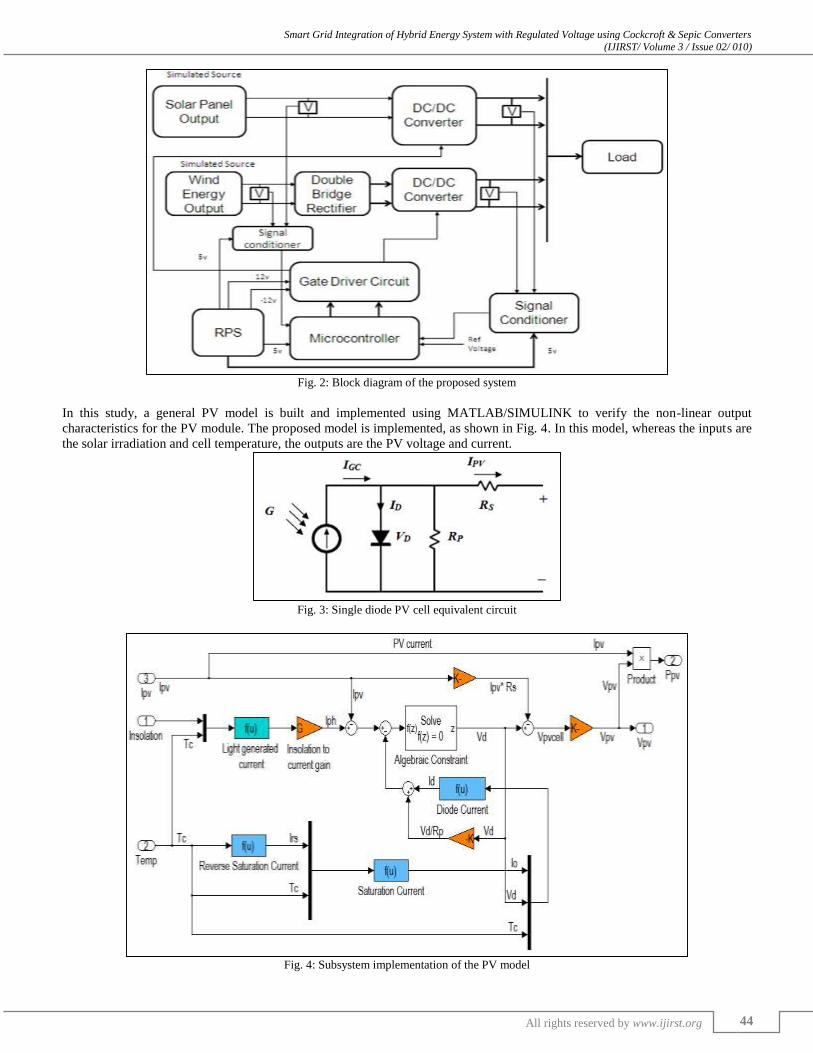
In this section, the dynamic simulation model is described for PV/wind turbine hybrid energy system. The developed system
consists of a photovoltaic array, DC/DC converter with an isolated transformer, designed for achieving the Maximum Power
Point with a current reference control (Iref) produced by P&O algorithm, wind turbine, asynchronous induction generator, and a
AC/DC Thyristor controlled double-bridge rectifier. The block diagram of the developed system is shown in Fig.2.
Modeling and Design of a Photovoltaic Module:
The general mathematical model for the solar cell has been studied over the last few decades. The circuit of the solar cell model,
which consists of a photocurrent, diode, parallel resistor (leakage current) and a series resistor; is shown in Fig.3. According to
both the PV cell circuit shown in Fig.3 and Kirchhoff’s circuit laws, the photovoltaic current can be presented as follows:
Ipv = Igc –Io [exp(evd
KFTc) – 1] -
Vd
Rp (1)
Where Igc is the light generated current, Io is the dark saturation current dependant on the cell temperature, e is the electric
charge = 1.6 x 10⁻¹⁹ Coulombs, K is Boltzmann’s
constant = 1.38 x 10⁻²³ J/K, F is the cell idealizing factor, Tc is the cell’s absolute temperature, Vd is the diode voltage, and
Rp is the parallel resistance. The photocurrent (Igc) mainly depends on the solar irradiation and cell temperature, which is
described as
Where μsc is the temperature coefficient of the cell’s short circuit current, Tref is the cell’s reference temperature, Isc is the
cell’s short circuit current at a 25 oc and 1KW/m2, and G is the solar irradiation in KW/m2. Furthermore, the cell’s saturation
current (Io) varies with the cell temperature
Where Ioα is the cell’s reverse saturation current at a solar radiation and reference temperature, Vg is the band-gap energy of the
semiconductor used in the cell, and Voc is the cells open circuit voltage.
Smart Grid Integration of Hybrid Energy System with Regulated Voltage using Cockcroft & Sepic Converters (IJIRST/ Volume 3 / Issue 02/ 010)
All rights reserved by www.ijirst.org 44
Fig. 2: Block diagram of the proposed system
In this study, a general PV model is built and implemented using MATLAB/SIMULINK to verify the non-linear output
characteristics for the PV module. The proposed model is implemented, as shown in Fig. 4. In this model, whereas the inputs are
the solar irradiation and cell temperature, the outputs are the PV voltage and current.
Fig. 3: Single diode PV cell equivalent circuit
Fig. 4: Subsystem implementation of the PV model

Smart Grid Integration of Hybrid Energy System with Regulated Voltage using Cockcroft & Sepic Converters (IJIRST/ Volume 3 / Issue 02/ 010)
All rights reserved by www.ijirst.org 45
Modeling and Design of a WT and Induction Generator
In this paper, the proposed WT model is based on the wind speed versus WT output power characteristics. The output power of
the wind turbine is given by:
Where Pm is the mechanical output power of the turbine, cp is the performance coefficient of the turbine, λ is the tip speed
ratio of the rotor blade, β is the blade pitch angle, ρ is the air density, A is the turbine swept area, and vwind is the wind speed.
The performance coefficient model cp (λ,β) used in this paper is given by:
Where constants c1 to c6 are the parameters that depend on the wind turbine rotor and blade design, and λi is a parameter given
as below.
Moreover, can be simplified for specific values of A and ρ, as in equation (8):
Where Pm-pu is the power in per unit (p.u.) of nominal power for particular values of ρ and A, vwind-pu is the p.u. value of the
base wind speed, cp-pu is the p.u. value of the performance coefficient cp, kp is the power gain. The based wind speed is the mean
value of the expected wind speed in (m/s).
The modified model of the WT is implemented as shown in Fig.5. In this model, whereas the inputs are the wind speed and
generator speed, the output is the torque applied to the generator shaft. The torque of the generator depends on the generator
power and speed.
Fig. 5: Subsystem implementation of the WT model
The wind turbine induction generator model is designed using the SimPower System library. The rotor shaft is driven by the
WT which produces the mechanical torque according to the generator and wind speed values. The electrical power output of the
generator (stator winding) is connected to the smart grid.
Power Control Systems
Photovoltaic Control System
The PV model output characteristics with different cell temperature and solar irradiance are non-linear. In addition, maximum
power point (MPP) of the PV module changes continuously because the solar irradiation is unpredictable. Therefore, it is
required to operate the PV module at its maximum power point (MPP) by using maximum power point tracker (MPPT)
Smart Grid Integration of Hybrid Energy System with Regulated Voltage using Cockcroft & Sepic Converters (IJIRST/ Volume 3 / Issue 02/ 010)
All rights reserved by www.ijirst.org 46
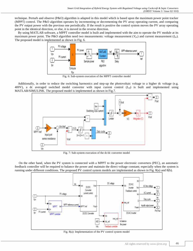
technique. Perturb and observe (P&O) algorithm is adapted in this model which is based upon the maximum power point tracker
(MPPT) control. The P&O algorithm operates by incrementing or decrementing the PV array operating current, and comparing
the PV output power with the previous one periodically. If the result is positive the control system moves the PV array operating
point in the identical direction, or else, it is moved in the reverse direction.
By using MATLAB software, a MPPT controller model is built and implemented with the aim to operate the PV module at its
maximum power point. The P&O algorithm need two measurements: voltage measurement (Vpv) and current measurement (Ipv).
The proposed model is implemented as shown in Fig. 6.
Fig. 6: Sub-system execution of the MPPT controller model
Additionally, in order to reduce the switching harmonics and step-up the photovoltaic voltage to a higher dc voltage (e.g.
400V), a dc averaged switched model converter with input current control (Iref) is built and implemented using
MATLAB/SIMULINK. The proposed model is implemented as shown in Fig.7.
Fig. 7: Sub-system execution of the dc/dc converter model
On the other hand, when the PV system is connected with a MPPT to the power electronic converters (PEC), an automatic
feedback controller will be required to balance the power and maintain the direct voltage constant; especially when the system is
running under different conditions. The proposed PV control system models are implemented as shown in Fig. 8(a) and 8(b).
Fig. 8(a): Implementation of the PV control system model

Smart Grid Integration of Hybrid Energy System with Regulated Voltage using Cockcroft & Sepic Converters (IJIRST/ Volume 3 / Issue 02/ 010)
All rights reserved by www.ijirst.org 47
Fig. 8(b): Subsystem implementation of the feedback controller model
Wind Turbine Control System
The output of the wind turbine induction generator experiences variations in frequency and amplitude due to the variations in
wind speed. Consequently, a controllable AC/DC converter is used in order to smooth the wind turbine output power prior to
being supplied to other electronic devices.
The schematic of the double-bridge rectifier is shown in Fig. 9.
Fig. 9: The Double-Bridge Rectifier
We can achieve the best advantage of the double-bridge rectifier which is controllable dc output voltage by tuning the firing
angle (α) of the 12-pulse synchronized PWM generator and by narrowing the commutation periods, which causes less harmonic
distortion effects on the source side. In this paper, a three-phase two winding transformer is used to obtain six input ports with
suitable phase angles for the double-bridge rectifier. The control of the firing angle (α) is done by a discrete PI controller. The
proposed Wind Turbine control system model is shown in Fig. 10.
Fig. 10: The double-bridge rectifier, filters elements and control system model.
DC/AC inverter for load side
An ac switched model inverter is built and implemented using MATLAB/SIMULINK, to switch the direct current (DC) into
alternating current (AC), at a switching frequency (fs) greater than the AC line frequency (50Hz -60Hz). Losses are included due

Smart Grid Integration of Hybrid Energy System with Regulated Voltage using Cockcroft & Sepic Converters (IJIRST/ Volume 3 / Issue 02/ 010)
All rights reserved by www.ijirst.org 48
to input-port switching loss current (IIP) and output-port series resistance (ROP). The proposed model is implemented as shown
in Fig. 11.
Fig. 11: Sub-system implementation of the DC/AC inverter model
Sepic Converter
A SEPIC converter is a new non-isolated bi-directional soft switching with reduced ripple currents is proposed to overcome the
problems due to hard-switching. The diodes are replaced by active switches for bi-directional power flow control and a small
inductor is added to the auxiliary power delivery path, as shown in the modified SEPIC topology in Fig.12. With the use of a
single circuit structure, the operations of the SEPIC converter are implemented in the forward and reverse directions,
respectively. Similar to the features of original bi-directional SEPIC converter, both step-up and step-down operations are
accessible regardless of power conversion directions.
Fig. 12: Sepic Converter
Cockcroft Converter
The conventional Cockcroft-Walton voltage multiplier is very popular among high voltage DC applications. The proposed
converter provides higher voltage ratio than that of the conventional CW voltage multiplier, by replacing the step-up transformer
with the boost type structure. The proposed converter operates in continuous conduction mode, so that EMI noise, switching
stresses and the switching losses can be reduced.

Smart Grid Integration of Hybrid Energy System with Regulated Voltage using Cockcroft & Sepic Converters (IJIRST/ Volume 3 / Issue 02/ 010)
All rights reserved by www.ijirst.org 49
Fig. 13: n-stage CW voltage multiplier
III. SIMULATION RESULTS AND DISCUSSION
The block diagram of the integrated PV/WT systems, and the power controllers are shown in Fig. 2. The main inputs for the
proposed PV model were solar irradiation, PV manufacturing data sheet information’s and PV panel temperature. In this paper,
Astronergy CHSM6610P PV panel is taken as example. The Astronergy CHSM6610P key specification is listed in Table I. Table – 1
Stronergy CHSM6610P specifications (1kW/m2, 25o C)
Parameter Value
Maximum power (Pm) 225 (W)
Open circuit voltage (Voc) 36.88 (V)
Voltage at Pm (Vamp) 29.76 (V)
Short circuit current (Isc) 8.27 (A)
Current at Pm (Iamp) 7.55 (A)
Temp coefficient for Pm -0.46 (% / oC)
Temp coefficient for Voc -0.129 (V / oC)
Temp coefficient for Isc + 0.052 (% / °C)
No. of cells and connections 60 in series
The P-V and V-I output characteristics for the PV model are shown in Fig.12 The output power and current of PV module
depends on the solar irradiance, temperature, as well as cell’s terminal operating voltage. It is noticed from Fig. 12(a) and 12(b)
that with increase in solar irradiance there is an increase in both the maximum power output and the short circuit current.
Alternatively, we observe from Fig. 12(c) and 12(d) that due to increase in the cell temperature, the maximum power output
decreases while the short circuit current increases.

Smart Grid Integration of Hybrid Energy System with Regulated Voltage using Cockcroft & Sepic Converters (IJIRST/ Volume 3 / Issue 02/ 010)
All rights reserved by www.ijirst.org 50
Fig. 12: V-I and P-V output characteristics (a - b) with different G (c - d) with different Tc
The parameters of the WT induction generator are given in Table II. Table – 2
Wind Turbine Induction generator parameters
Parameter Value
Turbine data
Base wind speed (wbase) 9 (m/s)
Maximum power at wbase (kp) 1 (p.u.)
Coefficient (c1-c6) [0.5176, 116, 0.4, 5, 21,0.0068]
Nominal performance coefficient 0.48 (p.u.) for [β =0o, λ=8.1 ]
Generator data
Rotor type Squirrel cage
Nominal power (Pmechanic) 200 (HP)
Nominal voltage (line-to-line) 460 (V)
Nominal revolutions per minute 1785 (rpm)
Stator resistance 0.01282 (p.u.)
Stator inductance 0.05051 (p.u.)
Rotor resistance 0.00702 (p.u.)
Rotor inductance 0.05051 (p.u.)
Magnetizing inductance 6.77 (p.u)
Inertia constant 0.3096 (s)
Friction factor 0.0114 (p.u.)
Pairs of poles 2
The generator power (p.u.) and its speed (rpm) characteristics for the WT model are shown in Fig. 13 with respect to various
wind speed values. The output power of the wind turbine depends on the wind speed and generator speed. As shown in Fig.13,
wind speed is the most prominent factor on the amount of power produced by the wind turbine. As the power of the wind is a
cubic function of wind speed, so the changes in speed produces a profound effect on power.

Smart Grid Integration of Hybrid Energy System with Regulated Voltage using Cockcroft & Sepic Converters (IJIRST/ Volume 3 / Issue 02/ 010)
All rights reserved by www.ijirst.org 51
Fig. 13: Wind turbine characteristics
The parameters of the boost type DC/DC converter located at the output of the PV system are given in Table III.
The parameters of the Thyristor controlled double-bridge rectifier are given in Table IV. Table – 3
DC/DC converter model parameters
Parameter Value
Input port series resistance 0.5
Switching loss current 0.03
Capacitance 200 (μF)
Initial capacitor voltage 400 (V)
Table – 4
Double-bridge rectifier model parameters
Parameter Value
Pulse width of synchronized 12-pulse generator 80 (degree)
Proportional gain of PI voltage control system 2
Integral gain of PI voltage control system 20
Snubber resistance of one thyristor 2 (kΩ)
Snubber capacitance of one thyristor 0.1 (μF)
Internal resistance of one thyristor 1 (mΩ)
Filter inductance 66 (mH)
Filter capacitance 3300 (μF)
Reference voltage 400 (V)
Finally, Table V shows the parameters of the input transformer used in the double-bridge rectifier. Table – V
Transformer parameters
Parameter Value
Nominal power 120 (kW)
Nominal frequency 60 (Hz)
Input winding parameter [460 (V) 0.00025 (p.u.) 0 (p.u.)]
(Yg) [V1 R1 L1] Output winding parameter [230 (V) 0.00025 (p.u.) 0.0024 (p.u.)]
(Y) [V2 R2 L2] Output winding parameter [230 (V) 0.00025 (p.u.) 0.0024 (p.u.)]
(Delta) [V3 R3 L3]
Magnetization resistance 368.62 (p.u.)
Magnetization inductance 368.62 (p.u.)
Smart Grid Integration of Hybrid Energy System with Regulated Voltage using Cockcroft & Sepic Converters (IJIRST/ Volume 3 / Issue 02/ 010)
All rights reserved by www.ijirst.org 52
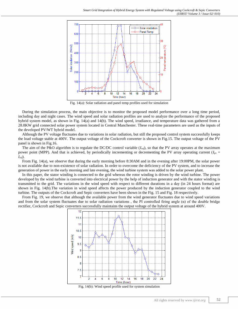
Fig. 14(a): Solar radiation and panel temp profiles used for simulation
During the simulation process, the main objective is to monitor the proposed model performance over a long time period,
including day and night cases. The wind speed and solar radiation profiles are used to analyze the performance of the proposed
hybrid system model, as shown in Fig. 14(a) and 14(b). The wind speed, irradiance, and temperature data was gathered from a
28.8KW grid connected solar power system located in Central Manchester. These real-time parameters are used as the inputs of
the developed PV/WT hybrid model.
Although the PV voltage fluctuates due to variations in solar radiation, but still the proposed control system successfully keeps
the load voltage stable at 400V. The output voltage of the Cockcroft converter is shown in Fig.15. The output voltage of the PV
panel is shown in Fig.16.
The aim of the P&O algorithm is to regulate the DC/DC control variable (Iref), so that the PV array operates at the maximum
power point (MPP). And that is achieved, by periodically incrementing or decrementing the PV array operating current (Ipv =
Iref).
From Fig. 14(a), we observe that during the early morning before 8:30AM and in the evening after 19:00PM, the solar power
is not available due to non-existence of solar radiation. In order to overcome the deficiency of the PV system, and to increase the
generation of power in the early morning and late evening, the wind turbine system was added to the solar power plant.
In this paper, the stator winding is connected to the grid whereas the rotor winding is driven by the wind turbine. The power
developed by the wind turbine is converted into electrical power by the help of induction generator and with the stator winding is
transmitted to the grid. The variations in the wind speed with respect to different durations in a day (in 24 hours format) are
shown in Fig. 14(b).The variation in wind speed affects the power produced by the induction generator coupled to the wind
turbine. The outputs of the Cockcroft and Sepic converters have been shown in the Fig. 15 and Fig. 18 respectively.
From Fig. 19, we observe that although the available power from the wind generator fluctuates due to wind speed variations
and from the solar system fluctuates due to solar radiation variations , the PI controlled firing angle (α) of the double bridge
rectifier, Cockcroft and Sepic converters successfully maintains the output voltage of the hybrid system at around 400V.
Fig. 14(b): Wind speed profile used for system simulation

Smart Grid Integration of Hybrid Energy System with Regulated Voltage using Cockcroft & Sepic Converters (IJIRST/ Volume 3 / Issue 02/ 010)
All rights reserved by www.ijirst.org 53
Since the voltage of the two dc buses is kept at 400V, DC/AC inverters are used to deliver the required power to the load side
at 50Hz frequency and 240V line-to-line voltage. The power delivered to the load side by the PV/WT hybrid topology is
illustrated in Fig. 20.
Fig. 15: Output Voltage of Cockcroft Converter
Fig. 16: Output Voltage of Solar Energy System
Fig. 17: Output voltage of the Wind Energy System
Fig. 18: Output Voltage of Sepic Converter

Smart Grid Integration of Hybrid Energy System with Regulated Voltage using Cockcroft & Sepic Converters (IJIRST/ Volume 3 / Issue 02/ 010)
All rights reserved by www.ijirst.org 54
Fig. 19: AC Grid Voltage and Current
Fig. 20: Power delivered to load side by the hybrid topology
IV. CONCLUSIONS
In this paper, a novel PV/WT hybrid power system is modeled and designed for smart grid applications. The developed
algorithm comprises system components and an appropriate power flow controller. The model has been implemented using the
MATLAB/SIMULINK software package, and designed with a dialog box like those used in the SIMULINK block libraries. The
available power from the PV system is highly depends on solar radiation and in order to overcome this deficiency of the PV
system, the PV module was integrated with the wind turbine (WT) system. The dynamic operating conditions. Solar irradiance,
temperature and wind speed data is gathered from a 28.8kW grid connected solar power system located in central Manchester.
The output of the developed hybrid system is able to deliver constantly 400V. The developed system and its control strategy
exhibit excellent performance for the simulation of a complete day. The proposed model offers a proper tool for smart grid
performance optimization.
REFERENCES
[1] E. Miller, “Smart grids – a smart idea?,” Renewable Energy Focus Magazine, vol. 10, pp. 62-67, Sep.-Oct. 2009. [2] H. Yang, Z. Wei, and L. Chengzh, “Optimal design and technoeconomic analysis of a hybrid solar-wind power generation system,” Applied Energy, vol.
86, pp. 163-169, Feb. 2009.
[3] S. Dihrab, and K. Sopian, “Electricity generation of hybrid PV/wind systems in Iraq,” Renewable Energy, vol. 35, pp. 1303-1307, Jun. 2010. [4] J.P. Reichling, and F.A. Kulacki, “Utility scale hybrid wind-solar thermal electrical generation: a case study for Minnesota,” Energy, vol. 33, pp.626-638,
Apr. 2008.
[5] O. Ekren, B.Y. Ekren, and B. Ozerdem, “Break-even analysis and size optimization of a PV/wind hybrid energy conversion system with battery storage – A case study” Applied Energy, vol.86, pp. 1043-1054, July-August 2009.
[6] S.K. Kim, J.H. Jeon, C.H. Cho, E.S. Kim, and J.B. Ahn, “Modeling and simulation of a grid-connected PV generation system for electromagnetic transient
analysis, ”Solar Energy, vol.83, pp. 664- 678, May 2009. [7] H.L Tsai, “Insolation-oriented model of photovoltaic module using Matlab/Simulink,” Solar Energy, vol. 84, pp. 1318-1326, July 2010.
[8] J.A. Gow, and C.D. Manning, “Development of a photovoltaic array model for use in power-electronics simulation studies,” IEE Proceedings- Electric
Power Applications, vol. 146, pp. 193-199, Mar. 1999.

Smart Grid Integration of Hybrid Energy System with Regulated Voltage using Cockcroft & Sepic Converters (IJIRST/ Volume 3 / Issue 02/ 010)
All rights reserved by www.ijirst.org 55
[9] M.J. Khan, and M.T. Iqbal, “Dynamic modeling and simulation of a small wind fuel cell hybrid energy system,” Renewable Energy, vol. 30, pp. 421-439,
Mar. 2005. [10] N. Chayawatto, K. Kirtikara, V. Monyakul, C. Jivacate, and D. Chenvidhya, “DC–AC switching converter modelings of a PV grid-connected system under
islanding phenomena,” Renewable Energy, vol. 34, pp. 2536-2544, Dec. 2009.
[11] O.C. Onara, M. Uzunoglua, and M.S. Alam, “Dynamic modeling, design and simulation of a wind/fuel cell/ultra-capacitor-based hybrid power generation system, “Journal of Power Sources, vol. 161, pp. 707-722, Oct. 2006.
[12] J.C.H. Phang, D.S.H. Chan, and J.R. Philips, “Accurate analytical method for the extraction of solar cell model parameter,” IEEE Electronics Letters,vol.
20, pp.406-408, May 1984.


![Implementation of SEPIC/Zeta Three-Port Bidirectional DC ...vanished by introducing the multiport dc-dc converter [5-6]. These multi-port dc-dc converters can interface several number](https://static.fdocuments.in/doc/165x107/5f3cc4b88e446c087f3c5e0b/implementation-of-sepiczeta-three-port-bidirectional-dc-vanished-by-introducing.jpg)