
Smart Energy Profile 2.0 Marketing Requirements
310
ZigBee+HomePlug Joint Working Group – MRD Page 1 of 310 ZigBee+HomePlug Joint Working Group Smart Energy Profile Marketing Requirements Document (MRD) Draft Revision 1.0 March 11, 2009 MRD Overview This document is the Marketing Requirements Document (MRD) for the Smart Energy Profile and represents the next generation market requirements for Smart Energy and supporting use cases. Smart Energy enables both wired and wireless communication between utility companies and everyday household devices such as smart thermostats and appliances. Captured in this MRD are details for the next generation of functionality envisioned for the Smart Grid with accompanying consumer control. It includes insight to a variety of use cases including plug-in electric vehicle (PEV) charging, installation, configuration, firmware download for HAN devices, prepay services, user information and messaging, load control, demand response, common information, and application profile interfaces for wired and wireless HANs (Home Area Networks). It was jointly developed by ZigBee Alliance members, HomePlug Powerline Alliance members, utilities, regulators, suppliers and technology providers as a foundation for an enhanced ZigBee Smart Energy profile and as the basis for global standards development by other organizations. On May 18, the ZigBee/HomePlug Smart Energy profile was selected by the U.S. Department of Energy and the National Institute of Standards and Technology (NIST) as an initial interoperable standard for HAN devices and communications and information model. The development of the Smart Energy Profile drew upon the collective experience of members involved in the current development and deployment of the existing wireless ZigBee Smart Energy standard. Certified products and services based on this standard are available for use today from a variety of ZigBee members. The standard is supported by a comprehensive certification process that delivers secure, robust, reliable, plug and play interoperability with advanced metering infrastructure (AMI) and Smart Grid applications. Also, there are companies that are members of both the ZigBee Alliance and HomePlug Alliance that are beginning to implement the technology over powerline networks. This document will serve as the basis for a following Technical Requirements Document (TRD), which is the next step in line with creating the actual specification. Once these steps are complete, the specification will be made publicly available for companies and vendors to design, build and market products and services to further enable the smart grid and consumer energy control. The authors of this document thank all stakeholders for their collaboration, vision and leadership in forging the smart energy market. For more information about the ZigBee Alliance and the HomePlug Powerline Alliance, visit the web sites: www.zigbee.org and www.homeplug.org.
Transcript of Smart Energy Profile 2.0 Marketing Requirements

ZigBee+HomePlug Joint Working Group – MRD Page 1 of 310
ZigBee+HomePlug Joint Working Group
Smart Energy ProfileMarketing Requirements Document (MRD)
Draft Revision 1.0
March 11, 2009
MRD Overview
This document is the Marketing Requirements Document (MRD) for the Smart Energy Profile and represents the next generation market requirements for Smart Energy and supporting use cases. Smart Energy enables both wired and wireless communication between utility companies and everyday household devices such as smart thermostats and appliances. Captured in this MRD are details for the next generation of functionality envisioned for the Smart Grid with accompanying consumer control. It includes insight to a variety of use cases including plugin electric vehicle (PEV) charging, installation, configuration, firmware download for HAN devices, prepay services, user information and messaging, load control, demand response, common information, and application profile interfaces for wired and wireless HANs (Home Area Networks).
It was jointly developed by ZigBee Alliance members, HomePlug Powerline Alliance members, utilities, regulators, suppliers and technology providers as a foundation for an enhanced ZigBee Smart Energy profile and as the basis for global standards development by other organizations. On May 18, the ZigBee/HomePlug Smart Energy profile was selected by the U.S. Department of Energy and the National Institute of Standards and Technology (NIST) as an initial interoperable standard for HAN devices and communications and information model.
The development of the Smart Energy Profile drew upon the collective experience of members involved in the current development and deployment of the existing wireless ZigBee Smart Energy standard. Certified products and services based on this standard are available for use today from a variety of ZigBee members. The standard is supported by a comprehensive certification process that delivers secure, robust, reliable, plug and play interoperability with advanced metering infrastructure (AMI) and Smart Grid applications. Also, there are companies that are members of both the ZigBee Alliance and HomePlug Alliance that are beginning to implement the technology over powerline networks.
This document will serve as the basis for a following Technical Requirements Document (TRD), which is the next step in line with creating the actual specification. Once these steps are complete, the specification will be made publicly available for companies and vendors to design, build and market products and services to further enable the smart grid and consumer energy control. The authors of this document thank all stakeholders for their collaboration, vision and leadership in forging the smart energy market.
For more information about the ZigBee Alliance and the HomePlug Powerline Alliance, visit the web sites: www.zigbee.org and www.homeplug.org.

ZigBee+HomePlug Joint Working Group – MRD Page 2 of 310
Document Control
0.1 Ownership, Authorship
This Marketing Requirements Document was developed under the auspices of the ZigBee Alliance – HomePlug Powerline Alliance Joint Working Group.
Authorship of this document was a collaborative effort among the following major contributors:
Brent Hodges (Reliant Energy)Craig Rodine (Grid Net)Craig Tinder (Reliant Energy)Ivan O’Neill (Southern California Edison)Larry Kohrmann (Oncor)Megan O’Brien (Pacific Gas & Electric)Mike Bourton (HomePlug Powerline Alliance)Paul Kramarz (American Electric Power)Rhonda Sesek (Reliant Energy)Shelley Moister (L+G)Tom Herbst (Cisco Systems)Tom Martin (BC Hydro)Tony Mauro (BC Hydro)
0.2 Revision History
Rev # Date Description Main author(s)0.1 01132009 Incorporated front matter (Sections 05) IO, MB, CR0.2 01202009 Revisions and additions to Sections 06 CT, PK, TM, CR
0.3 01282009 Revisions and additions to Sections 06; moved Section 4.1.11 to Appendix A; added Appendix B MB, PK, RS, TM, CR
0.4 01302009 Revisions and additions to Sections 5, 6 IO, LK, PK, TM, CR
0.5 02042009 Incorporated changes from 01302009 call and subsequent work offline LK, MB, PK, TM, CR
0.6 020609 Refined Methodology (Section 1), Guiding Principles (Section 2); requirements (Section 6).
IO, LK, MB, PK, TM, CR
0.7 030209 Incorporated new requirements, many changes All0.85 030609 Incorporated modified format from TWG BH, CT
0.9 030709 Tweaked HighLevel Requirements (Section 2) and detailed requirements (Section 4) All
0.95 031009 Continued tweaking HighLevel Requirements (Section 2) and detailed requirements (Section 4) All
0.98 031109 Cleanup and penultimate review All1.0 031109 Final version 1.0 All

ZigBee+HomePlug Joint Working Group – MRD Page 3 of 310
Introduction and Narrative
0.3 Purpose and Problem Statement
The role of the HAN for managing energy usage is a crucial factor in addressing the world’s growing energy concerns. The Smart Energy initiative serves these needs by providing an adoptable and sustainable experience by linking new and useful digital technologies to the needs of consumers. By empowering consumers with near realtime information of their energy usage through an array of products and services, the intent is to help consumers use energy more efficiently and also to minimize their personal impact on the environment.
In addition, with a predicted mass global deployment of electric vehicles on the horizon, the home effectively becomes an electrical “filling station” for future transportation needs. This MRD includes a section on PluggableElectric Vehicles (PEVs) and how consumers can leverage an enhanced HAN to manage this new and unique transportation model.
The ZigBee + HomePlug Marketing Working Group has developed these Smart Energy profile requirements in order to further enhance earlier HAN specifications (specifically, the ZigBee Alliance Smart Energy Profile, v1.0) for utilities and product manufacturers and to help ensure a consistent, robust, and successful customer experience. The intent of the work done by ZigBee and HomePlug Alliance members is to submit these market requirements as a foundation for global standards adoption by other organizations and technologies.
This organization invites interested parties to provide insights and recommendations in order to further this very important global cause.
0.4 Methodology
The effort of creating system requirements was initiated by development of a thorough use case review and generation effort that was spearheaded by a range of subject matter experts crossing multiple industries. These volunteer individuals represent a variety of utilities and vendor partners that share a common goal of furthering the development and deployment of energy efficiency.
Many of the usecases herein include best practices and insights gleaned from existing resources within the energy industry. The following resources were leveraged in order to maintain consistency and compatibility across today’s standards work:
Utility AMI 2008 OpenHAN Use Cases Southern California Edison Use Cases Texas PUC Advanced Meter Use Cases ZigBee Alliance Smart Energy Profile 1.0
These new use cases were developed using the EPRI IntelligridSM use case template which has been adopted by many energy service providers and organizations within the industry.
The methodology for deriving the Market Requirements (Section 6) from the Use Cases follows the practice used by the UCAIug UtilityAMI OpenHAN Task Force. It borrows from the US Department of Energy’s GridWise Architecture Council’s Interoperability Framework for system decomposition. Using this structured approach, the guiding principles bound the system and frame the scope of the use cases. The Market Requirements are then extracted from the use cases by functional characteristic and criteria.
ZigBee+HomePlug Joint Working Group – MRD Page 4 of 310
It should be noted that the Market Requirements Document development team decided to defer the full technical analysis of the use cases to the Technical Working Group and instead focus on the overall requirements that the ZigBee and HomePlug technologies would need to meet (i.e., technology requirements). At the beginning of each use case description (Section 5), there is an indication of System Impact in terms of the categories depicted in the following highlevel, logical system breakdown from the UtilityAMI 2008 HAN SRS, which provides an Organizing Framework for this MRD:
0.5 PurposeThe goal of the ZigBee+HomePlug collaboration is to:
“Develop a common system architecture and application profile interfaces for home energy devices, supported by a comprehensive certification process that delivers secure, robust, reliable, plug and play interoperability with AMI and Smart Grid applications.”1
0.6 ScopeThis document pertains to the Home Area Network (HAN), which spans from the edge of the AMI System, where the Energy Services Interface resides, to all relevant HAN Devices in the home. It presents the requirements, use cases, highlevel architecture and deployment scenarios of version 2 of the Smart Energy profile that HomePlug and ZigBee technologies must support.
The scope of this effort is bounded by the projected timeline for this collaboration, and by the requirement to use the ratified ZigBee Smart Energy v1.0 profile as a baseline.
0.7 Guiding PrinciplesIn addition to the UtilityAMI 2008 HAN SRS v1.04 guiding principles listed below, the ZigBee+HomePlug collaboration Steering Committee has identified the following guiding principles:
! Open standards based
A public specification that is maintained by an open, public consensus process to accommodate new technology over time and that is consistent with standards. Open standards lower total cost of ownership and provide an open platform that encourages innovation.
! Robust and comprehensive certification process
Robust certification processes are needed to guarantee a seamless user experience that minimizes support calls and builds consumer confidence in the maturity of the HAN concept.
! Clean, layered architecture
1 ZB+HP Joint Working Group presentation, Vancouver, BC – 9 October 2008 <http://www.zhweb.org/mydms/out/out.ViewDocument.php?documentid=12>
ZigBee+HomePlug Joint Working Group – MRD Page 5 of 310
Adherence to industry best practices for software and systems development is a guiding principle. Specifically, the ZigBee+HomePlug collaboration will follow a clean, layered OSI architecture model. This allows standardization of the higher levels of the stack toprovide modularity and use of multiple transport layers.
! Focus on the application programming interfaces and not specific applications
Identifying the interfaces between applications and the core information sets available provides a minimum set of attributes to enable the required functionality. This enables a platform for innovation upon which a wide range of applications can be designed and built to suit users’ requirements and preferences while maintaining adherence to the open standard.
The UtilityAMI 2008 Home Area Network System Requirements Specification Guiding Principles are reprinted here for context and to signify their importance:
! Secure Twoway Communication Interface with the Meter
DescriptionThe capabilities of the system begin with the basic expectation that the AMI Meter has secure twoway communication to the Energy Services Interface (ESI), regardless of where the ESI is located. The meter contains consumerspecific energy information and is best suited to provide the HAN with near realtime access to the data.
The ESI also possesses a secure twoway communication interface for HAN Devices registered with the Utility.
RationaleThe twoway communications expectation defines the AMItoHAN interface and creates and enables all other capabilities within the system. This interface may carry various data types including, sensitive data, confidential data, and control data. Appropriate levels of security must be provided for these types of communications. Security is critical; the security implementation protects Utility and Consumer assets while enabling the next generation of applications and capabilities.
! Supports Load Control Integration
DescriptionLoad control is the concept of load being deferrable. A load control device has the capability to limit the duty cycle of equipment under control. Certain devices within the consumer’s premise (e.g., PCTs, electric pumps) can be used to shed load through direct and indirect control.
RationaleA capability to interface and integrate with load control systems enables the Utility’s value proposition, and as such, it is critical that the capability be extended to the HAN. In addition to load control interfacing and integration, the HAN system has several consumer enabling capabilities. These capabilities include direct access to usage data and pricing information. This data is generated by the meter and provides additional justification for direct meter interaction.
ZigBee+HomePlug Joint Working Group – MRD Page 6 of 310
! Direct Access to Usage Data
DescriptionThis platform provides the HAN with direct access to Consumerspecific information and enables a new class of energy services and products.
RationaleOne of the main requirements for energy conservation is a better informed Consumer. With more timely and detailed information at the hands of the Consumer, he will be able to make better choices about energy usage and conservation. With direct data access, the Consumer does not need to wait until the end of the month to see how changes in his usage have affected his bill. And with energy usage profiled in smaller increments, the Consumer can see the impact of changing his energy usage patterns.
! Provides a Growth Platform for Future Products Which Leverage HAN and Meter Data
DescriptionA growth platform is typically a specifically named initiative selected by a business organization to fuel their revenue and earnings growth. The HAN is an example of a strategic growth platform. Strategic growth platforms are longer term initiatives where the initiative and results span multiple years. While AMI is the catalyst for HAN information exchange, the growth platform is not limited to the Utility, but to any organization that wants to create devices or services for the HAN.
RationaleBeyond information delivery and basic demand response, the Utility expects the HAN to support the next generation of applications including distributed generation, Plugin Hybrid Electric Vehicles, and other metering applications as the technology, information, and capabilities of the HAN matures. By supporting open standards (see Principle 8), it is expected many vendors will be able to bring capabilities and innovation to bear on the HAN market.
! Supports Three Types of Communications: Public Price Signaling, ConsumerSpecific Signaling, and Control Signaling
DescriptionTo support the anticipated market growth, the system must provide various types of communication. These communication types include public price signaling, consumerspecific signaling, and control signaling. Public pricing is the communication of material which is publicly available. Consumerspecific signaling would be signaling such as that which would support a home energy management system. Control signaling are those signals used to support loadshedding (see Principle 2).
RationaleEach signal type is required to support the HAN as a growth platform (see Principle 4). Each signal type warrants individual security and privacy analysis and treatment. As such, the Utility does not take accountability and does not provide specific handling recommendations. Consumerspecific information signaling implies a level of privacy and additional privacy measures and methods are warranted. Control signaling for load
ZigBee+HomePlug Joint Working Group – MRD Page 7 of 310
control and direct Utility communications is a special use of the system and as such, requires robust handling methods. This capability expectation is based on Utility accountability for safe and secure delivery of the control data.
! Supports Distributed Generation and EndUse Metering
DescriptionDistributed generation systems are smallscale power generation technologies used to provide an alternative to or an enhancement of the traditional electric power system. Enduse metering is the idea that a second meter may be installed in the premise to support distributed generation production or measurement of discreet loads. Additionally, the OpenHAN and UtilityAMI architecture does not presume use of only electric meters. The HAN ESI may also communicate with gas and water meters and propagate their data through the HAN (e.g., to an IHD) or through the AMI network for transfer to an appropriate entity (e.g., an electric utility could gather water meter information and pass that information to the water utility).
RationaleThe ability to support communication to multiple HAN Devices provides greater value to the Consumer and Utility by facilitating automation and reducing redundancy in the systems required to capture metering information. As more homes and business become “green” it is anticipated that the Utility will need to support distributed generation sources such as solar panels, small wind turbines, or Plugin Hybrid Electric Vehicle or Electric Vehicles that may discharge back into the network. Nonrevenue grade metering of enduse devices can provide consumers with additional information on the energy and cost associated with enduses such as individual circuits, appliances, or plug loads.
! Consumer Owns the HAN
DescriptionHAN ownership should not be confused with device ownership or communications accountability. Rather, Consumer ownership broadly defines the rights of the Consumer. Simply stated, the Consumer owns and controls the HAN.
RationaleThe Consumer for various reasons may concede control of their HAN. Typically, this concession is part of the normal Utility registration process for HAN Devices. That is, for certain types of communications the Consumer may allow Utility control.
! MetertoHAN Interface Is Based on Open Standards
DescriptionFrom the IEEE P1003.0 Committee:
"An open system is: A system that implements sufficient open specifications for interfaces, services, and supporting formats to enable properly engineered applications software to be ported across a wide range of systems with minimal changes, to interoperate with other applications on local and remote systems, and to interact with users in a style which facilitates user portability.”
ZigBee+HomePlug Joint Working Group – MRD Page 8 of 310
A key element of this definition is the term, “open specification,” which is defined as:“A public specification that is maintained by an open, public consensus process to accommodate new technology over time and that is consistent with standards.”
RationaleOpenness and accessibility are the keys to availability and prevalence. It also provides for a competitive market which drives down the price of Consumer goods. Requiring vendors to use nonproprietary standards puts competitive pressure on vendors because if any single vendor offers a proprietary solution, this is usually a stepping stone to increased maintenance and support costs.
The Utilities are constrained by the relative value of the HAN and any Utility investments needed to readily adapt to changes in the technology market. For this reason, this specification is written as platform and technology independent.
0.8 System Limits and Exclusions
This SRS does not apply to Utility systems beyond the Energy Services Interface like the AMI Meter (which, however, may support an ESI to the HAN), Utility Communications Network, and Meter Data Collection and Management Systems. It also does not extend past HAN Devices in the home that do not reside on a Utilitysecured communications channel (described in more detail in OpenHAN SRS Section 2.2 – Architectural Considerations, and in Section 4 of this document, below). Some examples of HAN Devices not covered in the scope of this specification are home automation, home health monitoring, and security system products.
Future versions of the Smart Energy profile may address communications with other field devices upstream from the home or utility customer premise. This MRD focuses solely on premiseconnected devices.
ZigBee+HomePlug Joint Working Group – MRD Page 9 of 310
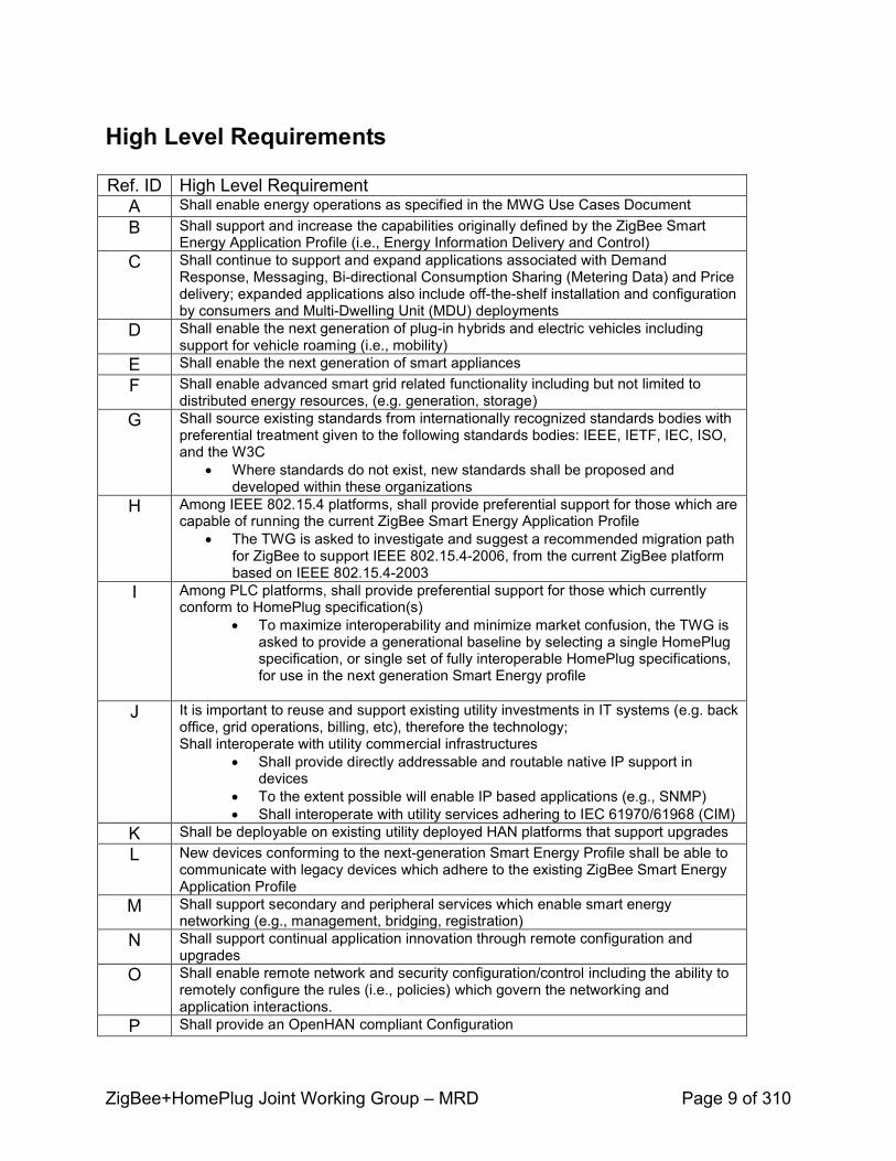
High Level Requirements
Ref. ID High Level RequirementA Shall enable energy operations as specified in the MWG Use Cases DocumentB Shall support and increase the capabilities originally defined by the ZigBee Smart
Energy Application Profile (i.e., Energy Information Delivery and Control)C Shall continue to support and expand applications associated with Demand
Response, Messaging, Bidirectional Consumption Sharing (Metering Data) and Price delivery; expanded applications also include offtheshelf installation and configuration by consumers and MultiDwelling Unit (MDU) deployments
D Shall enable the next generation of plugin hybrids and electric vehicles including support for vehicle roaming (i.e., mobility)
E Shall enable the next generation of smart appliancesF Shall enable advanced smart grid related functionality including but not limited to
distributed energy resources, (e.g. generation, storage)G Shall source existing standards from internationally recognized standards bodies with
preferential treatment given to the following standards bodies: IEEE, IETF, IEC, ISO, and the W3C
! Where standards do not exist, new standards shall be proposed and developed within these organizations
H Among IEEE 802.15.4 platforms, shall provide preferential support for those which are capable of running the current ZigBee Smart Energy Application Profile
! The TWG is asked to investigate and suggest a recommended migration path for ZigBee to support IEEE 802.15.42006, from the current ZigBee platform based on IEEE 802.15.42003
I Among PLC platforms, shall provide preferential support for those which currently conform to HomePlug specification(s)
! To maximize interoperability and minimize market confusion, the TWG is asked to provide a generational baseline by selecting a single HomePlug specification, or single set of fully interoperable HomePlug specifications,for use in the next generation Smart Energy profile
J It is important to reuse and support existing utility investments in IT systems (e.g. back office, grid operations, billing, etc), therefore the technology;Shall interoperate with utility commercial infrastructures
! Shall provide directly addressable and routable native IP support in devices
! To the extent possible will enable IP based applications (e.g., SNMP)! Shall interoperate with utility services adhering to IEC 61970/61968 (CIM)
K Shall be deployable on existing utility deployed HAN platforms that support upgradesL New devices conforming to the nextgeneration Smart Energy Profile shall be able to
communicate with legacy devices which adhere to the existing ZigBee Smart Energy Application Profile
M Shall support secondary and peripheral services which enable smart energy networking (e.g., management, bridging, registration)
N Shall support continual application innovation through remote configuration and upgrades
O Shall enable remote network and security configuration/control including the ability to remotely configure the rules (i.e., policies) which govern the networking and application interactions.
P Shall provide an OpenHAN compliant Configuration

ZigBee+HomePlug Joint Working Group – MRD Page 10 of 310
Appendix A: Use Cases
HAN Device Installation
0.8.1 System impact per categories
Installation requirements fit primarily within the Operations Maintenance and Logistics section of the system level breakdown.
0.8.2 Business drivers and motivation
An easy installation process is critical for the success of HAN programs
o Installation is the first step in the process o If consumers can’t get past the installation step, nothing else happenso The ideal solution would be a seamless, plugandplay experience for the
consumer
Consideration was given to how HAN Devices will be acquired by the Customer (from their Utility/REP or from a third party such as a Retail channel) and who does installation (Professional Installation / Utility or Contractor, or Customer Selfinstallation)
o Mass Market adoption of HAN Devices will only occur when the Customer can selfinstall a wide selection of products available through Retail channels such as those used in the consumer electronics industry.
o Most Utilities are not planning to enter the product business to offer HAN Devices on the scale of a typical consumer electronic company.
0.8.3 References and access to external sources, if any
Use cases reviewed for HAN Device installation came from the following sources: Public Utilities Commission Texas [PUCT]—AMIT Project, American Electric Power, BC Hydro, Reliant Energy, SCE 2006 use case library, UtilityAMI OpenHAN, and the ZigBee Smart Energy MRD.
The PUCT use cases were used as a baseline because their process involved participation at open hearings of a cross section of market participants including: Regulators, Transmission and Distribution Utilities, Retail Electric Providers, AMI and meter vendors, consumer advocates, device manufacturers, system integrators and other interested parties. Additionally, the PUCT workshops were focused on implementation details to enable HAN functionality within the competitive deregulated electricity market in Texas. This cross section of experts and focus on the HAN in a multiparty landscape led to more extensive requirement development than in other previous work surveyed.
ZigBee+HomePlug Joint Working Group – MRD Page 11 of 310
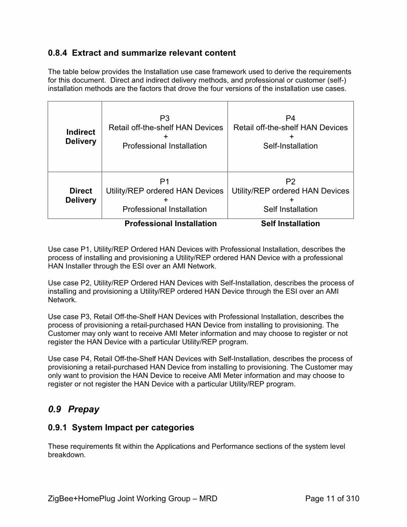
0.8.4 Extract and summarize relevant content
The table below provides the Installation use case framework used to derive the requirements for this document. Direct and indirect delivery methods, and professional or customer (self) installation methods are the factors that drove the four versions of the installation use cases.
Indirect Delivery
P3 Retail offtheshelf HAN Devices
+ Professional Installation
P4Retail offtheshelf HAN Devices
+SelfInstallation
Direct Delivery
P1Utility/REP ordered HAN Devices
+ Professional Installation
P2Utility/REP ordered HAN Devices
+ Self Installation
Professional Installation Self Installation
Use case P1, Utility/REP Ordered HAN Devices with Professional Installation, describes the process of installing and provisioning a Utility/REP ordered HAN Device with a professional HAN Installer through the ESI over an AMI Network.
Use case P2, Utility/REP Ordered HAN Devices with SelfInstallation, describes the process of installing and provisioning a Utility/REP ordered HAN Device through the ESI over an AMI Network.
Use case P3, Retail OfftheShelf HAN Devices with Professional Installation, describes the process of provisioning a retailpurchased HAN Device from installing to provisioning. The Customer may only want to receive AMI Meter information and may choose to register or not register the HAN Device with a particular Utility/REP program.
Use case P4, Retail OfftheShelf HAN Devices with SelfInstallation, describes the process of provisioning a retailpurchased HAN Device from installing to provisioning. The Customer may only want to provision the HAN Device to receive AMI Meter information and may choose to register or not register the HAN Device with a particular Utility/REP program.
0.9 Prepay
0.9.1 System Impact per categories
These requirements fit within the Applications and Performance sections of the system level breakdown.

ZigBee+HomePlug Joint Working Group – MRD Page 12 of 310
0.9.2 Business drivers and motivation
Prepay allows certain classes of customers the option of paying in advance for their electricity usage. Trials have indicated this method allows customers to effectively budget and then monitor their usage and money remaining on account, and adjust their usage accordingly.
Prepay directly impacts the utilities bottom line by reducing utilities collection activity, reducing exposure to chargeoffs, allowing recovery of outstanding debt, promoting conservation, increasing customer satisfaction, and improving company image.
The largest benefit prepay provides for the utility is the reduction of residential chargeoffs. Chargeoff rates vary based on geographic location and economic conditions; a typical utility might chargeoff approximately 0.5% of gross residential revenues. It is preferable for the utility to minimize chargeoffs which improves cash flow. Prepay offers a means to significantly reduce residential chargeoffs.
0.9.3 References and access to external sources, if any
Specific Use Cases referenced in developing the Prepay Use Cases and requirements are listed below.
Source Source Use Case reference #American Electric Power, Indiana Smart Meter Pilot Program: Home Area Network Use Cases, v1.3
2.9.6
Southern California Edison use cases, ARCH C3 USE CASE v1.2 Customer prepays for electric services
C3
0.9.4 Extract and summarize relevant content
The customer contacts the utility to prepay for electrical service at their home. The customer provides the payment amount and payment information to the utility using various payment methods. The utility verifies funds and applies the prepayment amount on the customer’s account. The utility uses AMI to transmit the prepayment information to the meter at the customer’s site. The meter will receive, log and activate electrical service at the customer’s site.
The utility will provide the customer various warning messages alerting the customer when their prepayment balance on the meter is low, with a forecasted amount of the time remaining before the prepaid account balance reaches zero. This information will be passed onto a display device in the customer home. Utility meter disconnect rules and the customer’s account balance determine eligibility for disconnect. Once eligible, the utility will issue a command for disconnect and electrical service at the customer’s home will be automatically disconnected. Customer payment results in immediate notification of payment to the utility and the customer is reconnected. The display device is also capable of receiving energy messages from the meter that enables the customer to proactively manage their energy use.
ZigBee+HomePlug Joint Working Group – MRD Page 13 of 310
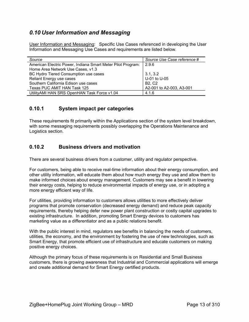
0.10 User Information and Messaging
User Information and Messaging: Specific Use Cases referenced in developing the User Information and Messaging Use Cases and requirements are listed below.
Source Source Use Case reference #American Electric Power, Indiana Smart Meter Pilot Program: Home Area Network Use Cases, v1.3
2.9.6
BC Hydro Tiered Consumption use cases 3.1, 3.2 Reliant Energy use cases U01 to U05Southern California Edison use cases B2, C2 Texas PUC AMIT HAN Task 125 A2001 to A2003, A3001UtilityAMI HAN SRS OpenHAN Task Force v1.04 4.1.6
0.10.1 System impact per categories
These requirements fit primarily within the Applications section of the system level breakdown, with some messaging requirements possibly overlapping the Operations Maintenance and Logistics section.
0.10.2 Business drivers and motivation
There are several business drivers from a customer, utility and regulator perspective.
For customers, being able to receive realtime information about their energy consumption, and other utility information, will educate them about how much energy they use and allow them to make informed choices about energy management. Customers may see a benefit in lowering their energy costs, helping to reduce environmental impacts of energy use, or in adopting a more energy efficient way of life.
For utilities, providing information to customers allows utilities to more effectively deliver programs that promote conservation (decreased energy demand) and reduce peak capacity requirements, thereby helping defer new power plant construction or costly capital upgrades to existing infrastructure. In addition, promoting Smart Energy devices to customers has marketing value as a differentiator and as a public relations benefit.
With the public interest in mind, regulators see benefits in balancing the needs of customers, utilities, the economy, and the environment by fostering the use of new technologies, such as Smart Energy, that promote efficient use of infrastructure and educate customers on making positive energy choices.
Although the primary focus of these requirements is on Residential and Small Business customers, there is growing awareness that Industrial and Commercial applications will emerge and create additional demand for Smart Energy certified products.
ZigBee+HomePlug Joint Working Group – MRD Page 14 of 310
0.10.3 References and access to external sources, if any
The two associated use cases for User Information and Messaging were created based on input from many sources, which are referenced in Appendix A.
Many pilots are underway to determine if user information and user messages to an energy monitoring device impacts peak load reduction. Some documented results suggest energy consumption reductions of between 515%. Additionally, an energy monitoring device may generate a sense of control resulting in energy conservation, especially among low income groups and people with high bills. Long term studies have been started to determine the extent and persistence of customer behavior. Results of pilots and these studies will assist utilities with their implementation of cost effective residential efficiency programs.
Sources: EPRI: 1016088 Residential Energy Display Devices; EPRI: P170.012 Persistence of Customer Response to Direct Energy Feedback Systems (065582).
0.10.4 Extract and summarize relevant content
The Use Cases form an integral part in understanding the context and application of these requirements. Together, they describe the information that may be desired by the EndUser and that could be displayed or otherwise communicated to the EndUser via a HAN Device. In addition, these requirements describe the messages that would flow from the Utility to a HAN Device to invoke configuration changes, gather status, or perform control actions
These requirements do not specify where the information or messages originate; however they assume the messages are communicated through the Smart Energy module in the Meter. For example, it does not specify whether information is stored in the meter and sent to the HAN Device or whether information originates from the Utility. As well, it does not assume that any calculations are performed in the HAN Device nor does it intend to be prescriptive of IHD functionality. Lastly, the use cases and requirements do not detail how the EndUser would interact with the HAN device to retrieve the information but solely focuses on the messaging within the HAN.
0.11 PEV Charging
0.11.1 System impact per categories Plugin electric vehicles (PEVs) impact the entire system due to their portability across multiple HANs. They share similar Applications with most load control devices and can respond to direct load control signals and pricebased signals. Portability of the devices requires new methods of registration and network rejoining that affect the Security requirements of the system. Operations, Maintenance, and Logistics may also be impacted by the structure of the vehicle sales model and channels.
0.11.2 Business drivers and motivationElectricity as a transportation fuel has emerged as the clear nearterm winner of the nonpetroleumbased fuels competition. Every major auto manufacturer has announced plans to commercialize a plugin electric vehicle, including a wide range of hybrid gasolineelectric, pure
ZigBee+HomePlug Joint Working Group – MRD Page 15 of 310
electrics, and others. The first of these – the Toyota plugin Prius and the Chevy Volt – will be offered in the market between mid2010 and early 2011.
Increased penetration of electric drive train vehicles creates challenges and opportunities for electric service providers tasked with maintaining the reliability of the grid and managing peak energy demands. Electric vehicle loads today are in the range of 1.5kW to 10kW. Electric service providers will need to integrate these new load sources carefully in order to avoid disrupting or damaging the electric grid we all rely on for our daily lives. The primary way to do this is through classic demand side management programs that communicate peak events, price signals, or other charging management messages.
With electric vehicles, the number of fueling locations (i.e., electrical outlets) increases exponentially over the existing petroleumbased infrastructure. A wide range of transaction methods will exist in the market. One method relevant to this effort describes a way to correlate and allocate vehicle charging with the charging location, vehicle location, and the vehicle operator’s billing account that is transparent to the customer. This could utilize the HAN infrastructure being deployed by utilities and potentially reduce the need to install expensive, weatherized transaction terminals at every plug. Finally, it could allow vehicle roaming across electric service provider territories similar to the way cell phones behave today.
0.11.3 References
Use cases were contributed primarily by Southern California Edison, the Society of Automotive Engineers J2836 committee, and the Electric Power Research Institute’s Infrastructure Working Council.
0.11.4 Extract and summarize relevant content
[To be added in TRD]
0.12 Load Control / Demand Response
[To be added in TRD]
0.13 Exceptions and Errors Use Case
0.13.1 System impact per categories
[To be added in TRD]
0.13.2 Business drivers and motivation
The proper handling of errors and exceptions will improve the customer experience and reduce the support costs by:
ZigBee+HomePlug Joint Working Group – MRD Page 16 of 310
! The system identifies a problem and the system or utility personnel rectifies the situation without consumer intervention or
! By providing the Consumer or Installer with feedback on the incorrect actions that have been taken and suggesting the appropriate steps for recovery
This will improve the installation success rate, reduce the product returns with no fault found and reduce the number of support calls.
The aim of the use cases is to anticipate the situations that may result in unsuccessful operation and provide a process that ensures prompt success with a target of zero support calls.
0.13.3 References and access to external sources, if any
The use cases were derived from American Electric Power Indiana Smart Meter Pilot Program: Home Area Network Use Cases Version 1.3
0.13.4 Extract and summarize relevant content
The use cases deal with the following situations:
! HAN device fails to respond or report to the ESI! ESI detects abnormal communication activity! AMI meter needs replacing! IT security determines a need to roll encryption keys! HAN device fails or is replaced
0.14 HAN Device FirmWare Download
[To be added in TRD]
ZigBee+HomePlug Joint Working Group – MRD Page 17 of 310
Appendix A: Supporting Requirements (all)
Requirements Framework
0.15 Requirements Assumptions
The chart below depicts a decomposition of the HAN system into levels of abstraction and functional categories. It was developed for use in the UtilityAMI OPenHAN efforts, and reused by the ZBHP MRD team to drive the process of categorizing and harmonizing new use cases, and deriving detailed platformindependent requirements therefrom.

ZigBee+HomePlug Joint Working Group – MRD Page 18 of 310
ZigBee+HomePlug Joint Working Group – MRD Page 19 of 310
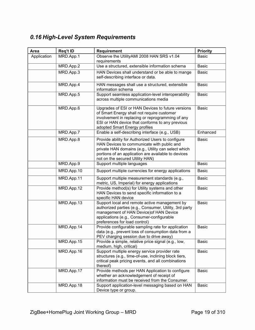
0.16 HighLevel System Requirements
Area Req’t ID Requirement PriorityApplication MRD.App.1 Observe the UtilityAMI 2008 HAN SRS v1.04
requirementsBasic
MRD.App.2 Use a structured, extensible information schema BasicMRD.App.3 HAN Devices shall understand or be able to mange
selfdescribing interface or data.Basic
MRD.App.4 HAN messages shall use a structured, extensible information schema
Basic
MRD.App.5 Support seamless applicationlevel interoperability across multiple communications media
Basic
MRD.App.6 Upgrades of ESI or HAN Devices to future versions of Smart Energy shall not require customer involvement in replacing or reprogramming of any ESI or HAN device that conforms to any previous adopted Smart Energy profiles
Basic
MRD.App.7 Enable a selfdescribing interface (e.g., USB) Enhanced
MRD.App.8 Provide ability for Authorized Users to configure HAN Devices to communicate with public and private HAN domains (e.g., Utility can select which portions of an application are available to devices not on the secured Utility HAN)
Basic
MRD.App.9 Support multiple languages Basic
MRD.App.10 Support multiple currencies for energy applications Basic
MRD.App.11 Support multiple measurement standards (e.g., metric, US, Imperial) for energy applications
Basic
MRD.App.12 Provide method(s) for Utility systems and other HAN Devices to send specific information to a specific HAN device
Basic
MRD.App.13 Support local and remote active management by authorized parties (e.g., Consumer, Utility, 3rd party management of HAN Device)of HAN Deviceapplications (e.g., Consumerconfigurable preferences for load control)
Basic
MRD.App.14 Provide configurable sampling rate for application data (e.g., prevent loss of consumption data from a PEV charging session due to drive away)
Basic
MRD.App.15 Provide a simple, relative price signal (e.g., low, medium, high, critical)
Basic
MRD.App.16 Support multiple energy service provider rate structures (e.g., timeofuse, inclining block tiers, critical peak pricing events, and all combinations thereof)
Basic
MRD.App.17 Provide methods per HAN Application to configure whether an acknowledgement of receipt of information must be received from the Consumer.
Basic
MRD.App.18 Support applicationlevel messaging based on HAN Device type or group.
Basic

ZigBee+HomePlug Joint Working Group – MRD Page 20 of 310
MRD.App.19 Ability for nonESI HAN Devices to aggregate data from other HAN Devices within the premise, including among specific HAN groups.
Basic
MRD.App.20 Support broadcast messaging to all HAN devices. BasicMRD.App.21 Support configuration of a valid date/time/duration
for each piece of information or message, so that if it's not acted on, or responded to, it expires. Also used for displaying new information based on scheduled changes to information.
Basic
MRD.App.22 Support a configurable billing period date/time/duration, as another interval of time.
Basic
MRD.App.23 Support comparisons against a baseline of energy consumption and cost information (e.g., average user comparisons).
Basic
MRD.App.24 Make available Peak Demand per TOU/CPP period and Peak Demand per Billing Period
Basic
MRD.App.25 Make available other metrology information from the meter e.g. Volts, Amps, VAr, Power Factor, etc.
Basic
MRD.App.26 Make available temperature information received from the ESI or other HAN Device
Enhanced
MRD.App.27 Support for Billing Information (e.g., rate label, utility name, etc)
Basic
MRD.App.28 Support variable length text messages (e.g., freeform messages conveying Information, Configuration, Status, Control)
Basic
MRD.App.29 Technology shall provide the ability to measure discrete enduse loads for utility programs, i.e. billing PEV charging at preferential rates.
Basic
MRD.App.30 The PEV shall be informed of the initiation and termination of a valid utility program session.
Basic
MRD.App.31 Methods to support negotiation of an energy request with ESI, e.g. for PEV charging purposes. This might include requested charge amount (in KWh) requested charge time, charging start and end time(s), available charge amount, charging rate, etc.,
Basic
MRD.App.32 Support onboard PEV calculations, e.g cost per distance.
Basic
MRD.App.33 Make available information to calculate estimated bill, e.g. billing cycle, data, monthly Consumer charges, taxes & franchise fee, surcharges,discounts, ratcheted demand, bond charges.
Enhanced
MRD.App.34 HAN devices shall accept user preference to display values of less than 1.00 currency unit incents.
Optional
MRD.App.35 Ability to time stamp messages communicated through the ESI Basic
MRD.App.36 Ability for ESI to send retry of control message upon failure of confirmation from HAN device Basic
MRD.App.37 Cancellation of an advanced scheduled demand response event Enhanced
ZigBee+HomePlug Joint Working Group – MRD Page 21 of 310
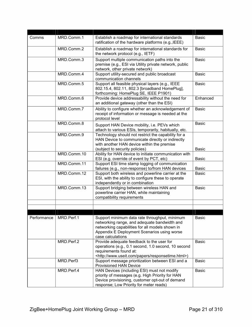
Comms MRD.Comm.1 Establish a roadmap for international standards ratification of the hardware platforms (e.g.,IEEE)
Basic
MRD.Comm.2 Establish a roadmap for international standards for the network protocol (e.g., IETF)
Basic
MRD.Comm.3 Support multiple communication paths into the premise (e.g., ESI via Utility private network, public network, other private network)
Basic
MRD.Comm.4 Support utilitysecured and public broadcast communication channels
Basic
MRD.Comm.5 Support all feasible physical layers (e.g., IEEE 802.15.4, 802.11, 802.3 [broadband HomePlug], forthcoming: HomePlug SE, IEEE P1901)
Basic
MRD.Comm.6 Provide device addressability without the need for an additional gateway (other than the ESI)
Enhanced
MRD.Comm.7 Ability to configure whether an acknowledgement of receipt of information or message is needed at the protocol level
Basic
MRD.Comm.8 Support HAN Device mobility, i.e. PEVs which attach to various ESIs, temporarily, habitually, etc.
Basic
MRD.Comm.9 Technology should not restrict the capability for a HAN Device to communicate directly or indirectly with another HAN device within the premise (subject to security policies) Basic
MRD.Comm.10 Ability for HAN device to initiate communication with ESI (e.g. override of event by PCT, etc) Basic
MRD.Comm.11 Support ESI time stamp logging of communication failures (e.g., nonresponse) to/from HAN devices Basic
MRD.Comm.12 Support both wireless and powerline carrier at the ESI, with the ability to configure these to operate independently or in combination
Basic
MRD.Comm.13 Support bridging between wireless HAN and powerline carrier HAN, while maintaining compatibility requirements
Basic
Performance MRD.Perf.1 Support minimum data rate throughput, minimum networking range, and adequate bandwidth and networking capabilities for all models shown in Appendix E Deployment Scenarios using worse case calculations
Basic
MRD.Perf.2 Provide adequate feedback to the user for operations (e.g., 0.1 second, 1.0 second, 10 second requirements found at: <http://www.useit.com/papers/responsetime.html>)
Basic
MRD.Perf3 Support message prioritization between ESI and a Provisioned HAN Device
Basic
MRD.Perf.4 HAN Devices (including ESI) must not modify priority of messages (e.g. High Priority for HAN Device provisioning, customer optout of demand response; Low Priority for meter reads)
Basic
ZigBee+HomePlug Joint Working Group – MRD Page 22 of 310
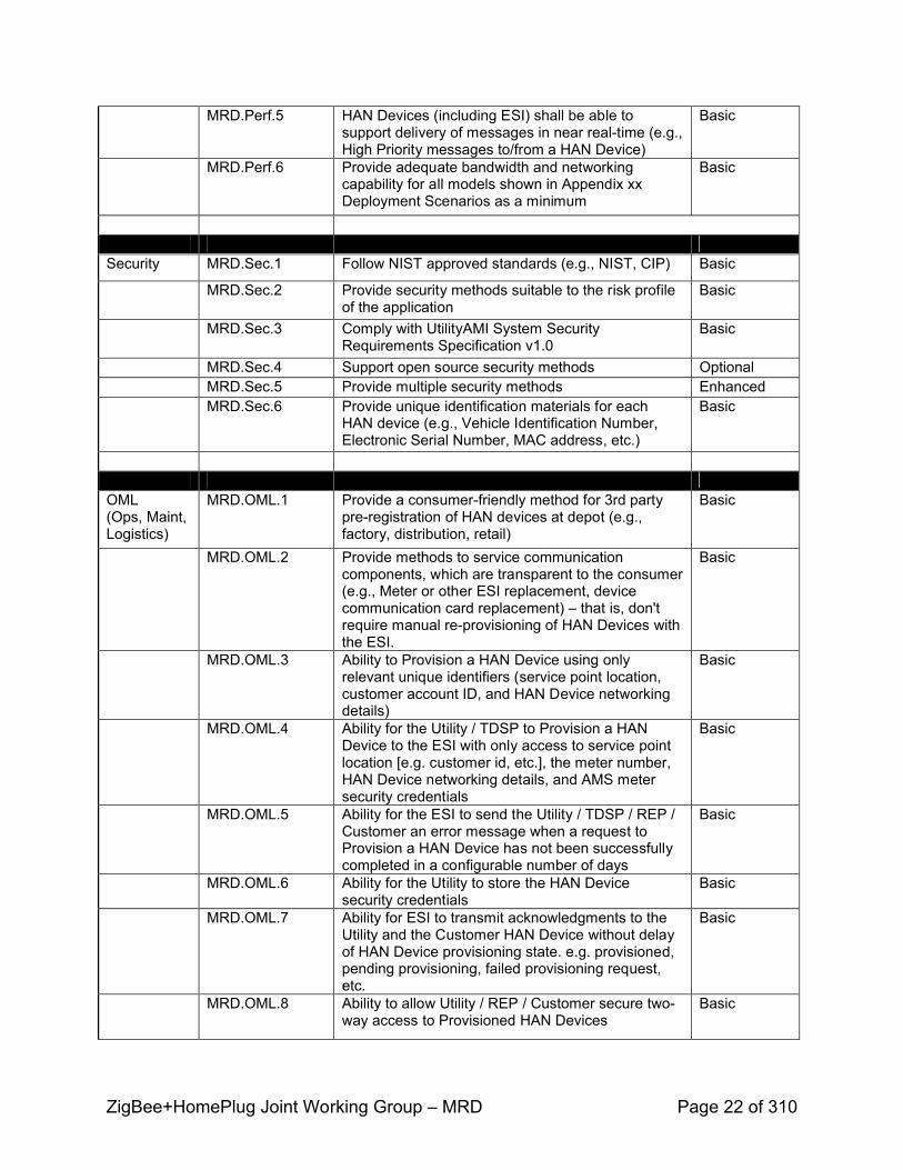
MRD.Perf.5 HAN Devices (including ESI) shall be able to support delivery of messages in near realtime (e.g., High Priority messages to/from a HAN Device)
Basic
MRD.Perf.6 Provide adequate bandwidth and networking capability for all models shown in Appendix xxDeployment Scenarios as a minimum
Basic
Security MRD.Sec.1 Follow NIST approved standards (e.g., NIST, CIP) Basic
MRD.Sec.2 Provide security methods suitable to the risk profile of the application
Basic
MRD.Sec.3 Comply with UtilityAMI System Security Requirements Specification v1.0
Basic
MRD.Sec.4 Support open source security methods OptionalMRD.Sec.5 Provide multiple security methods EnhancedMRD.Sec.6 Provide unique identification materials for each
HAN device (e.g., Vehicle Identification Number, Electronic Serial Number, MAC address, etc.)
Basic
OML(Ops, Maint,Logistics)
MRD.OML.1 Provide a consumerfriendly method for 3rd party preregistration of HAN devices at depot (e.g., factory, distribution, retail)
Basic
MRD.OML.2 Provide methods to service communication components, which are transparent to the consumer (e.g., Meter or other ESI replacement, device communication card replacement) – that is, don't require manual reprovisioning of HAN Devices with the ESI.
Basic
MRD.OML.3 Ability to Provision a HAN Device using only relevant unique identifiers (service point location, customer account ID, and HAN Device networking details)
Basic
MRD.OML.4 Ability for the Utility / TDSP to Provision a HAN Device to the ESI with only access to service point location [e.g. customer id, etc.], the meter number, HAN Device networking details, and AMS meter security credentials
Basic
MRD.OML.5 Ability for the ESI to send the Utility / TDSP / REP / Customer an error message when a request to Provision a HAN Device has not been successfully completed in a configurable number of days
Basic
MRD.OML.6 Ability for the Utility to store the HAN Device security credentials
Basic
MRD.OML.7 Ability for ESI to transmit acknowledgments to the Utility and the Customer HAN Device without delay of HAN Device provisioning state. e.g. provisioned, pending provisioning, failed provisioning request, etc.
Basic
MRD.OML.8 Ability to allow Utility / REP / Customer secure twoway access to Provisioned HAN Devices
Basic
ZigBee+HomePlug Joint Working Group – MRD Page 23 of 310
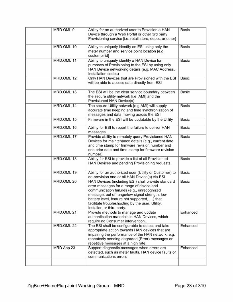
MRD.OML.9 Ability for an authorized user to Provision a HAN Device through a Web Portal or other 3rd party Provisioning service [i.e. retail store, depot, or other]
Basic
MRD.OML.10 Ability to uniquely identify an ESI using only the meter number and service point location [e.g. customer id]
Basic
MRD.OML.11 Ability to uniquely identify a HAN Device for purposes of Provisioning to the ESI by using only HAN Device networking details (e.g. MAC Address, Installation codes)
Basic
MRD.OML.12 Only HAN Devices that are Provisioned with the ESI will be able to access data directly from ESI
Basic
MRD.OML.13 The ESI will be the clear service boundary between the secure utility network [i.e. AMI] and the Provisioned HAN Device(s)
Basic
MRD.OML.14 The secure Utility network [e.g.AMI] will supply accurate time keeping and time synchronization of messages and data moving across the ESI
Basic
MRD.OML.15 Firmware in the ESI will be updatable by the Utility Basic
MRD.OML.16 Ability for ESI to report the failure to deliver HAN messages
Basic
MRD.OML.17 Provide ability to remotely query Provisioned HAN Devices for maintenance details (e.g., current date and time stamp for firmware revision number and one prior date and time stamp for firmware revision number)
Basic
MRD.OML.18 Ability for ESI to provide a list of all Provisioned HAN Devices and pending Provisioning requests
Basic
MRD.OML.19 Ability for an authorized user (Utility or Customer) to deprovision one or all HAN Device(s) via ESI
Basic
MRD.OML.20 HAN Devices (including ESI) shall provide standard error messages for a range of device and communication failures (e.g., unrecognized message, out of range/low signal strength, low battery level, feature not supported, …) that facilitate troubleshooting by the user, Utility, Installer, or third party.
Basic
MRD.OML.21 Provide methods to manage and update authentication materials in HAN Devices, which require no Consumer intervention..
Enhanced
MRD.OML.22 The ESI shall be configurable to detect and take appropriate action towards HAN devices that are impairing the performance of the HAN network, e.g. repeatedly sending degraded (Error) messages or repetitive messages at a high rate.
Enhanced
MRD.App.23 Support diagnostic messages when errors are detected, such as meter faults, HAN device faults or communications errors
Enhanced
ZigBee+HomePlug Joint Working Group – MRD Page 24 of 310
Appendix B: Full text of Use Cases
Home Area Network Use CasesBegins Page 37 of this document
Includes the following categories:1. Installation2. Prepay3. User information & messages4. PEV5. Load Control & Demand Response
###

ZigBee+HomePlug Joint Working Group – MRD Page 25 of 310
Appendix C: Supporting Information
Business Drivers and Market Motivation
0.17 Drive for Energy Conservation and Peak Demand Reduction
There is increasing awareness in many markets and geographies worldwide that energy conservation is a critical factor in reducing the production of greenhouse gases and checking their adverse impact on our climate. With the fluctuating cost of fossil fuels, conservation programs can also reduce economic risk and deliver real gains to producers and consumers, by reducing costs and delivering attractive returns on infrastructure investment. For reasons of energy security, too, there is increasing enthusiasm and support for energy conservation in nations that import fossil fuels.
Energy utilities have been taking initiatives, with encouragement or pressure from their regulators and unilaterally, to improve the efficiency of their operations by mitigating the effects of peak demand growth. This includes a range of demand side management programs from public service announcements to utility signaling of HVAC equipment and other high demand appliances when the electric grid approaches peak capacity.
These programs are now being expanded by utilities to include largerscale demand management: energy conservation and demand response programs designed to involve their retail customers. Models of consumerdriven demand response indicate energy savings – in particular, the ability to reduce peak load – that compare in economic and environmental impact to internal improvements and traditional commercialindustrial demandside management programs.
0.18 Consumerfocused Energy Management
[To be added in TRD]
0.19Market Geography and Size
As noted above, there is an emerging worldwide market for consumerdriven Smart Energy solutions. Estimates of the number of Smart Meters worldwide that will be installed over the next two decades are in excess of one billion. Each of these could have an Energy Services Interface, giving a reasonable first approximation of the number of retail customers who would be in the market for HANbased smart energy devices.
Some technologies – for example, standards for HAN communications (IEEE 802.15, IEEE P1901) – are being adopted worldwide. Some business and regulatory factors are similar in various markets, but some are quite different, and have implications for the architecture and technology of HANbased energy management. For example, German regulations limiting the utility’s ability to affect devices in the consumer premise, drives a demanding requirement for meter energy reading.and display of consumption approximately every second..

ZigBee+HomePlug Joint Working Group – MRD Page 26 of 310
The aim of the Alliances is to design the next generation of Smart Energy profile with a worldwide market in mind. However, the applicability of this MRD may be limited by the fact that the use cases on which requirements are being based have their provenance in North American utilities, and naturally address their business processes and technical plant (i.e., distribution topology).
0.20 Established and Emerging Applications
Established: Demand Response; Retail Energy Pricing; Energy PrePay; Energy Usage / Information Display
Emerging: Plugin Hybrid / Electric Vehicle Charging; Energy Management in MultiDwelling Units (MDUs)
[To be added in TRD]

ZigBee+HomePlug Joint Working Group – MRD Page 27 of 310
Appendix D: Context, Acronyms, References
Architectural Considerations
Although OpenHAN SRS specifies that the architecture is non binding and the specification is architecturally agnostic, guidance is given here.
The following sections provide further clarification or details on the UtilityAMI 2008 Home Area Network System Requirements Specification Version 1.04 – August 19, 2008 – reference 1
0.20.1 Consumer Considerations
Consumer owned devices shall be designed for self install and will require a level of built in self help that may require additional information from the ESI, such as error codes.
The need for authentication, integrity and confidentiality must be balanced with making the customer self install experience transparent and rewarding as possible, while maintaining full security
At each step, sufficient information shall be provided so that provisioning and registration will be simple and self directed. All exceptions and errors shall be handled in a way that minimizes customer support calls.
0.21 Acronyms and Abbreviations
Acronym, Term Meaning Comments
AMI Advanced Metering Infrastructure
CPP Critical Peak Pricing
CSS Customer Service System
EMS Energy Management System
ESI Energy Services Interface
ESU Energy Supplying Unit
EUMD Energy Use Measurement Device
FHDMC Fixed Home Area Network Devices with Metering Capability
FRS Flat Rate Structures
HAN Home Area Network
IHD InHome Display
ISO Independent System Operator
ZigBee+HomePlug Joint Working Group – MRD Page 28 of 310
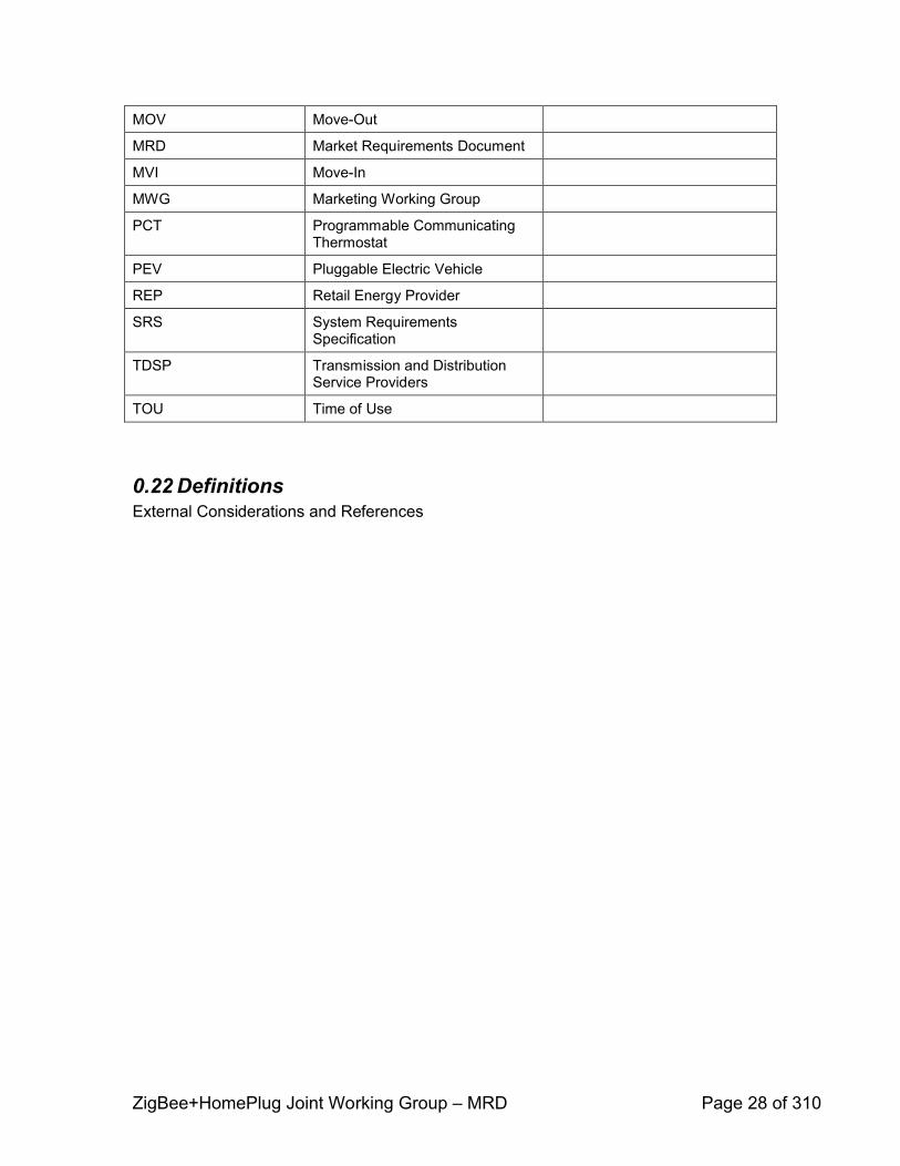
MOV MoveOut
MRD Market Requirements Document
MVI MoveIn
MWG Marketing Working Group
PCT Programmable Communicating Thermostat
PEV Pluggable Electric Vehicle
REP Retail Energy Provider
SRS System Requirements Specification
TDSP Transmission and Distribution Service Providers
TOU Time of Use
0.22 DefinitionsExternal Considerations and References
ZigBee+HomePlug Joint Working Group – MRD Page 29 of 310
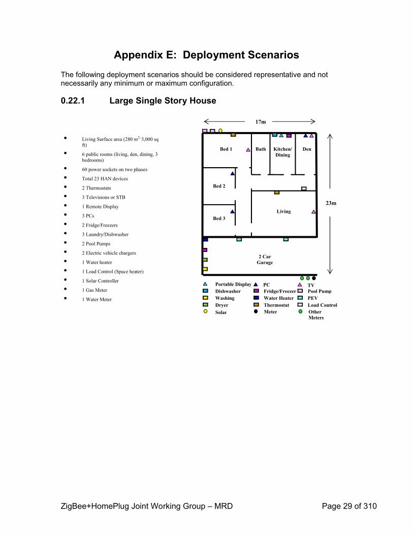
Appendix E: Deployment ScenariosThe following deployment scenarios should be considered representative and not necessarily any minimum or maximum configuration.
0.22.1 Large Single Story House
• Living Surface area (280 m2; 3,000 sq ft)
• 6 public rooms (living, den, dining, 3 bedrooms)
• 60 power sockets on two phases
• Total 23 HAN devices
• 2 Thermostats
• 3 Televisions or STB
• 1 Remote Display
• 3 PCs
• 2 Fridge/Freezers
• 3 Laundry/Dishwasher
• 2 Pool Pumps
• 2 Electric vehicle chargers
• 1 Water heater
• 1 Load Control (Space heater)
• 1 Solar Controller
• 1 Gas Meter
• 1 Water Meter
TV
17m
23mLiving
DenBathBed 1
Bed 2
Bed 3
Kitchen/Dining
Portable DisplayDishwasherWashing Dryer
Fridge/FreezerWater HeaterThermostat
Pool PumpPEVLoad Control
2 Car Garage
PC
Solar Meter Other Meters

ZigBee+HomePlug Joint Working Group – MRD Page 30 of 310
• Living Surface area (280 m2; 3,000 sq ft)
• 6 public rooms (living, den, dining, 3 bedrooms)
• 60 power sockets on two phases
• Total 23 HAN devices
• 2 Thermostats
• 3 Televisions or STB
• 1 Remote Display
• 3 PCs
• 2 Fridge/Freezers
• 3 Laundry/Dishwasher
• 2 Pool Pumps
• 2 Electric vehicle chargers
• 1 Water heater
• 1 Load Control (Space heater)
• 1 Solar Controller
• 1 Gas Meter
• 1 Water Meter
TV
17m
23mLiving
DenBathBed 1
Bed 2
Bed 3
Kitchen/Dining
Portable DisplayDishwasherWashing Dryer
Fridge/FreezerWater HeaterThermostat
Pool PumpPEVLoad Control
2 Car Garage
PC
Solar Meter Other Meters

ZigBee+HomePlug Joint Working Group – MRD Page 31 of 310
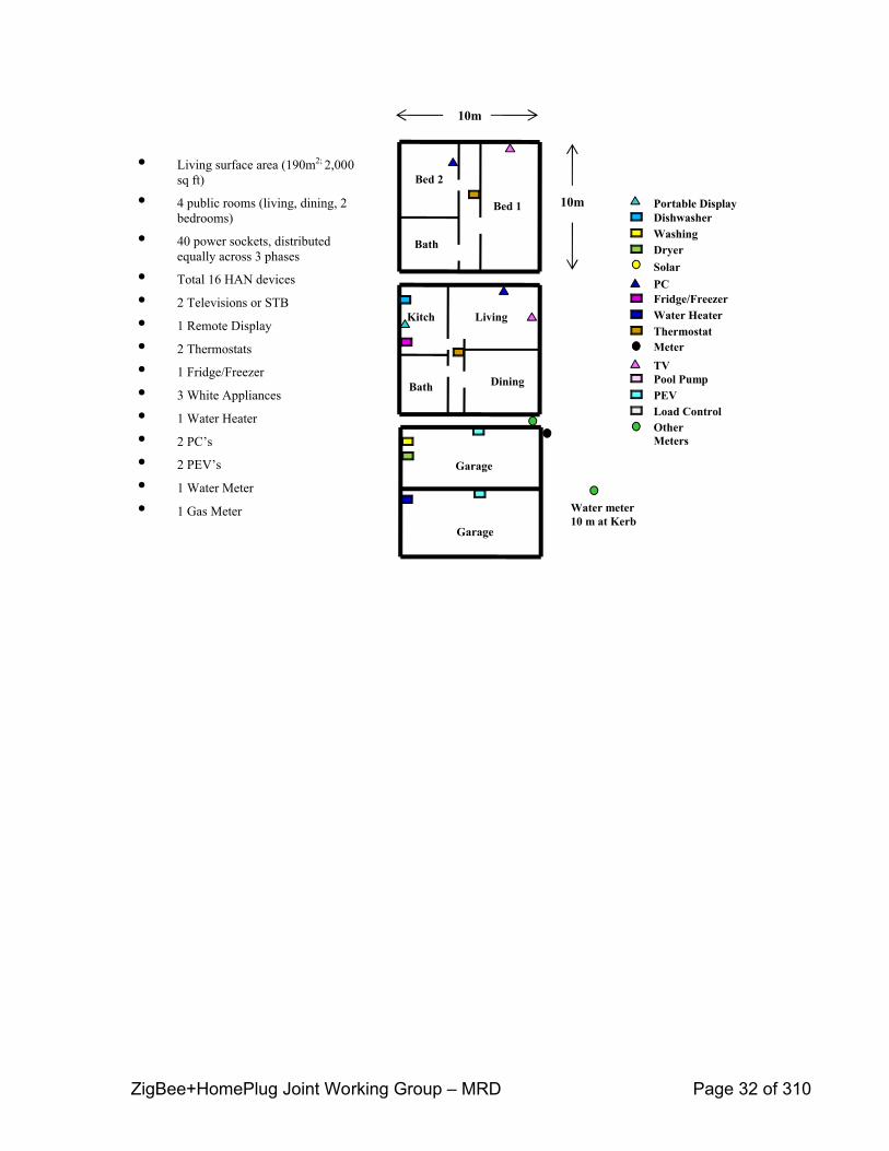
0.22.2 Medium Two Story House
• Living surface area (190m2; 2,000 sq ft)
• 4 public rooms (living, dining, 2 bedrooms)
• 40 power sockets, distributed equally across 3 phases
• Total 16 HAN devices
• 2 Televisions or STB
• 1 Remote Display
• 2 Thermostats
• 1 Fridge/Freezer
• 3 White Appliances
• 1 Water Heater
• 2 PC’s
• 2 PEV’s
• 1 Water Meter
• 1 Gas Meter
10m
10m
Living
DiningBath
Kitch
Bath
Bed 1
Bed 2
Garage
Garage
DishwasherWashing Dryer
Pool PumpPEVLoad Control
TV
Solar
Other Meters
Fridge/FreezerWater HeaterThermostat
PC
Meter
Portable Display
Water meter10 m at Kerb
ZigBee+HomePlug Joint Working Group – MRD Page 32 of 310
• Living surface area (190m2; 2,000 sq ft)
• 4 public rooms (living, dining, 2 bedrooms)
• 40 power sockets, distributed equally across 3 phases
• Total 16 HAN devices
• 2 Televisions or STB
• 1 Remote Display
• 2 Thermostats
• 1 Fridge/Freezer
• 3 White Appliances
• 1 Water Heater
• 2 PC’s
• 2 PEV’s
• 1 Water Meter
• 1 Gas Meter
10m
10m
Living
DiningBath
Kitch
Bath
Bed 1
Bed 2
Garage
Garage
DishwasherWashing Dryer
Pool PumpPEVLoad Control
TV
Solar
Other Meters
Fridge/FreezerWater HeaterThermostat
PC
Meter
Portable Display
Water meter10 m at Kerb
ZigBee+HomePlug Joint Working Group – MRD Page 33 of 310
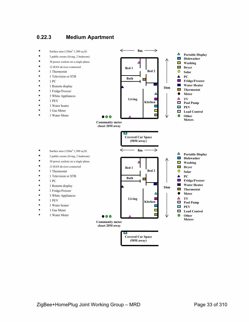
0.22.3 Medium Apartment
• Surface area (120m2; 1,300 sq ft)
• 3 public rooms (living, 2 bedroom)
• 30 power sockets on a single phase
• 12 HAN devices connected
• 1 Thermostat• 1 Television or STB• 1 PC• 1 Remote display• 1 Fridge/Freezer• 3 White Appliances• 1 PEV• 1 Water heater• 1 Gas Meter• 1 Water Meter
8m
16m
Living
Bed 1
Bath
Kitchen
Bed 2
DishwasherWashing Dryer
Pool PumpPEVLoad Control
TV
Solar
Other Meters
Fridge/FreezerWater HeaterThermostat
PC
Meter
Portable Display
Covered Car Space (50M away)
Community meter closet 20M away
ZigBee+HomePlug Joint Working Group – MRD Page 34 of 310
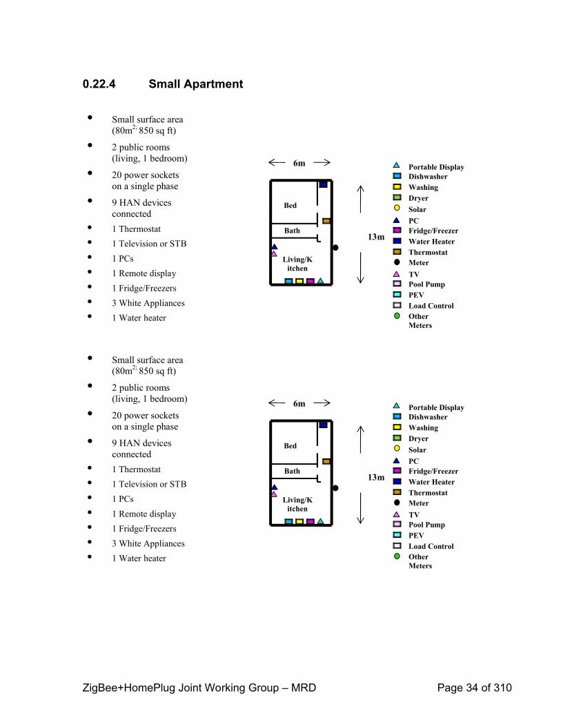
0.22.4 Small Apartment
• Small surface area (80m2; 850 sq ft)
• 2 public rooms (living, 1 bedroom)
• 20 power sockets on a single phase
• 9 HAN devices connected
• 1 Thermostat• 1 Television or STB• 1 PCs• 1 Remote display• 1 Fridge/Freezers• 3 White Appliances• 1 Water heater
6m
13m
Living/Kitchen
Bed
Bath
DishwasherWashing Dryer
Pool PumpPEVLoad Control
TV
Solar
Other Meters
Fridge/FreezerWater HeaterThermostat
PC
Meter
Portable Display

ZigBee+HomePlug Joint Working Group – MRD Page 35 of 310
0.22.5 MultiDwelling Unit (MDU)
Power
• MDU comprising 120 apartments:12 floors, 10 apartments per floor
• Each floor contains 5 (Scenario 3) medium, 5 small apartments
• 3 sub basement floors contain parking with single PEV/Bay
ZigBee+HomePlug Joint Working Group – MRD Page 36 of 310
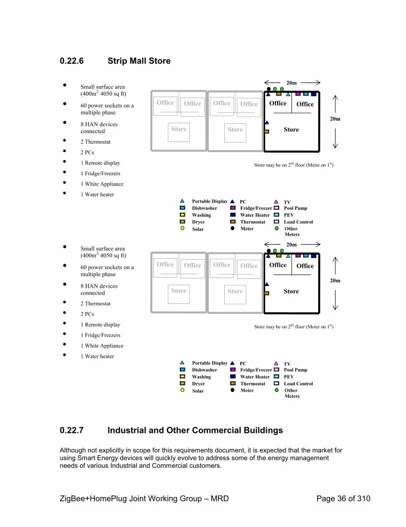
0.22.6 Strip Mall Store
0.22.7 Industrial and Other Commercial Buildings
Although not explicitly in scope for this requirements document, it is expected that the market for using Smart Energy devices will quickly evolve to address some of the energy management needs of various Industrial and Commercial customers.
TVPortable DisplayDishwasherWashing Dryer
Fridge/FreezerWater HeaterThermostat
Pool PumpPEVLoad Control
PC
Solar Meter Other Meters
20m
20m
Store
OfficeOffice
Store
OfficeOffice
Store
OfficeOffice
Store may be on 2nd floor (Meter on 1st)
• Small surface area (400m2; 4050 sq ft)
• 60 power sockets on a multiple phase
• 8 HAN devices connected
• 2 Thermostat
• 2 PCs
• 1 Remote display
• 1 Fridge/Freezers
• 1 White Appliance
• 1 Water heater
Appendix B
ZigBee+HomePlug Joint Working Group MRD Page 37 of 310
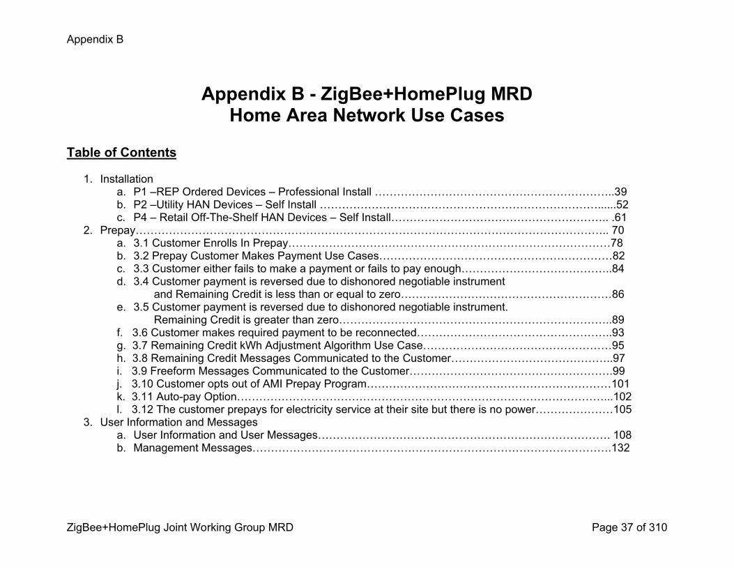
Appendix B ZigBee+HomePlug MRD Home Area Network Use Cases
Table of Contents
1. Installationa. P1 –REP Ordered Devices – Professional Install ………………………………………………………..39b. P2 –Utility HAN Devices – Self Install …………………………………………………………………......52c. P4 – Retail OffTheShelf HAN Devices – Self Install………………………………………………….. .61
2. Prepay……………………………………………………………………………………………………………….. 70a. 3.1 Customer Enrolls In Prepay……………………………………………………………………………78b. 3.2 Prepay Customer Makes Payment Use Cases………………………………………………………82c. 3.3 Customer either fails to make a payment or fails to pay enough…………………………………..84d. 3.4 Customer payment is reversed due to dishonored negotiable instrument and Remaining Credit is less than or equal to zero…………………………………………………86e. 3.5 Customer payment is reversed due to dishonored negotiable instrument. Remaining Credit is greater than zero………………………………………………………………..89f. 3.6 Customer makes required payment to be reconnected……………………………………………..93g. 3.7 Remaining Credit kWh Adjustment Algorithm Use Case……………………………………………95h. 3.8 Remaining Credit Messages Communicated to the Customer……………………………………..97i. 3.9 Freeform Messages Communicated to the Customer……………………………………………….99j. 3.10 Customer opts out of AMI Prepay Program…………………………………………………………101k. 3.11 Autopay Option………………………………………………………………………………………...102l. 3.12 The customer prepays for electricity service at their site but there is no power…………………105
3. User Information and Messagesa. User Information and User Messages……………………………………………………………………. 108b. Management Messages…………………………………………………………………………………….132

Appendix B
ZigBee+HomePlug Joint Working Group MRD Page 38 of 310
4. PEV Use Cases a. PEV Use Case 0 Customer enrolls in PHEV program, completes initial setup for PEV and implements connection and charging Cycles………………………………………………..148b. PEV Use Case 1 Utility provides services to Plugin Electric Vehicle (PEV) Customer…………..173 c. PEV Use Case 2 Customer connects Plugin Electric Vehicle (PEV) to premise energy portal………………………………………………………………………………………………..186d. PEV Use Case 3 Utility provides services to Plugin Electric Vehicle (PEV) Customer………… .211
5. Load Control and Demand Responsea. Utility Initiates Demand Response
i. L_02: 2.2 – Scenario 1: Utility initiates a demand response event……………………………225ii. L_02.1: 2.2 – Scenario 1: REP initiates a demand response event ………………………….231iii. L_07: 2.2 – Scenario 6: Subordinate of L_02: Utility initiates a demand response event. The PCT fails to respond…………………………………………………………………..238
iv. REP Sends a Load Control Event Request………………………………………………………242v. L_09 – Scenario 1: REP initiates a demand response event…………………………………..249vi. L_10 – Scenario 1: REP initiates a demand response event…………………………………..255vii. L_11 – Scenario 1: REP initiates a demand response event…………………………………..260viii. L_12 – Scenario 1: REP initiates a demand response event…………………………………..265ix. L_13 – Scenario 1: REP initiates a demand response event…………………………………..270x. L_14 – Scenario 1: REP initiates a demand response event…………………………………..275
b. Utility Demand Response – Opt out, Override, Cancellationi. Utility or 3rd party initiates and cancels a demand response event…………………………….281ii. Customer Overrides a Utility Initiated and Monitored Demand Response Event…………….286iii. Customer Opts out of AMI Demand Response Program………………………………………..291
c. HAN Device Requests and Respondsi. HAN Device requests load and energy management data from HAN device(s)……………..296ii. HAN Device responds to requests for load and energy management data…………………..300iii. HAN Device Sends State Changes to AMI Host System……………………………………….305
Appendix B
ZigBee+HomePlug Joint Working Group MRD Page 39 of 310
PUCTAMIT Task 158HAN Device Installation and Provisioning
P1 –REP Ordered Devices – Professional Install 01/09/2009
Appendix B
ZigBee+HomePlug Joint Working Group MRD Page 40 of 310
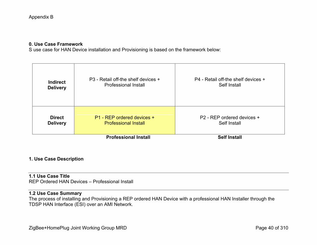
0. Use Case FrameworkS use case for HAN Device installation and Provisioning is based on the framework below:
Indirect Delivery
P3 Retail offthe shelf devices + Professional Install
P4 Retail offthe shelf devices + Self Install
Direct Delivery
P1 REP ordered devices + Professional Install
P2 REP ordered devices + Self Install
Professional Install Self Install
1. Use Case Description
1.1 Use Case TitleREP Ordered HAN Devices – Professional Install
1.2 Use Case SummaryThe process of installing and Provisioning a REP ordered HAN Device with a professional HAN Installer through the TDSP HAN Interface (ESI) over an AMI Network.
Appendix B
ZigBee+HomePlug Joint Working Group MRD Page 41 of 310
1.3 Use Case Detailed NarrativeOnce the AMS Network and AMS Meter is installed and the AMS Network is communicating with the ESI, the Customer is eligible for HAN Device installation. AMS Meter and premise information must be captured during AMS Meter installation by TDSP / Utility for use in Provisioning a HAN Device. Specifically, the AMS Meter information that is needed to address the ESI at the premise through the AMS Network is available to the TDSP. The AMS Meter at time of deployment is assumed to have no precommissioning of HAN Device networking details. The HAN Device is assumed to have no knowledge of security credentials for the AMS Meter HAN communications link.
The Customer triggers the fulfillment process by calling their REP and requesting a HAN Device. The Customer must identify themselves to their REP with their unique Customer id [e.g. Customer account, premise address, meter number, etc]. S information given to the REP must uniquely identify the Customer, the Customer premise and the specific AMS Meter for that premise. The REP will enter the necessary information into the REP CSS. The REP will initiate a HAN Device fulfillment request to the Logistics Provider (Internal or 3rd party). HAN Device networking details (e.g. MAC address, Installation Code) are electronically captured by the Logistics Provider prior to the HAN Device(s) being shipped to the Customer premise. The relevant HAN Device networking details are communicated by the Logistics Provider back to the REP where they are combined with the AMS Meter information and Customer information in the REP CSS. A possible exception path is that the HAN Installer could take the HAN Device(s) to the premise, but the HAN Installer would be expected to communicate the HAN Device networking details to the REP as a precondition for beginning the installation process.
The HAN Device Provisioning process is initiated by the REP through the REP CSS. S request is communicated to the ESI over the AMS Network by way of a REP accessible interface (e.g., API or user interface).The mechanism used in S use case for joining a HAN Device to the ESI is the ZigBee Smart Energy procedure (see ZigBee Smart Energy Profile r14, section 5.4.2.1). The ESI must be configured with security credentials derived from the installation codes of the HAN Device before the HAN Device attempts to join the AMS Meter’s Smart Energy HAN communication link. The appropriate HAN Device security credentials will be submitted to the appropriate ESI via the AMS Network from the REP CSS.
The HAN Device(s) arrive at the Customer premise and the ESI is prepared to allow the appropriate HAN Device(s) to join. All the HAN Installer has to do to provision the HAN Device to the ESI is to simply power the HAN Device and follow the HAN Device manufacturer’s instructions. The HAN Device will perform a secure transaction to join to its preconfigured
Appendix B
ZigBee+HomePlug Joint Working Group MRD Page 42 of 310
ESI. Following a successful join, the HAN Device is considered Provisioned and could engage in twoway communication through the ESI and over the AMS Network.
1.4 Business Rules and AssumptionsAssumptions
1. S P1 use case is typically for Residential Customers. 2. AMS Meter is installed at the premise and the AMS Network is communicating with the ESI. 3. The AMS Network has an accessible interface available to REPs or 3rd parties to communicate with the ESI.4. HAN communication in the premise is using the Smart Energy protocol. 5. All HAN Devices and the ESI must come from the manufacturer with valid security credentials loaded, that were issued by an authorized party as required by the Smart Energy specification.
6. HAN Devices have no knowledge of ESI security credentials when they are deployed.7. The AMS Meter information, which is obtained during installation of the AMS Meter, is available. 8. Customer has access to customer information (e.g. Customer account, premise address, meter number)..9. The Common Web Portal will provide an indication that a HAN Device is Provisioned to the ESI.10.The HAN Device will provide an indication of the success or failure to the Customer/installer of the Provisioning outcome with the ESI.
11.S use case shall conform to applicable national standards for Smart Energy and HAN applications as those standards develop.
12.Definitions Provisioning Establishing a secure communication link between the ESI and a HAN device such that
communications to and from the HAN device can be delivered over the AMS Network. S encompasses commissioning, beaconing, discovery. Provisioning on its own does not provide any link or communication between the HAN Device and the REP back office.
Registration Process of enrolling a HAN Device in a program in the REP CSS. Provisioning is a precondition of registering a HAN Device. Registration is out of scope for S use case.
DeProvisioning – Process of terminating the HAN Device communication with the AMS network through the ESI. S DeProvisioning process is out of scope for S use case and will be covered in another use case. See Tasks 157 and 172.
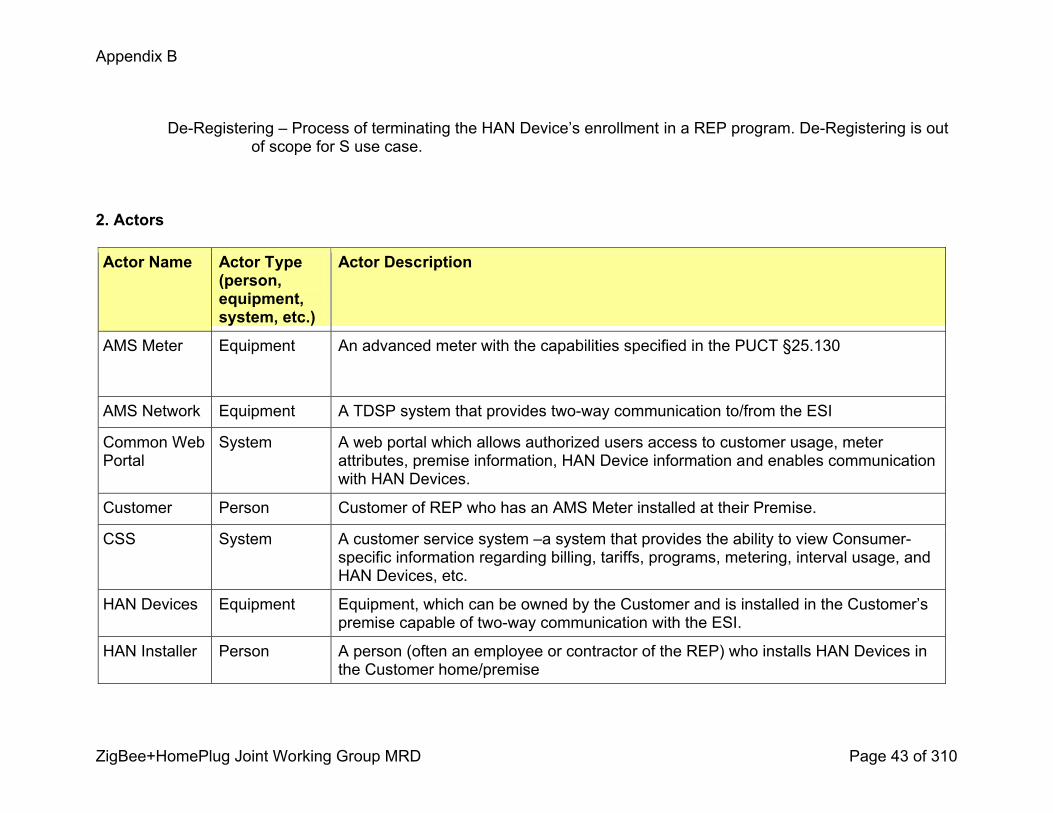
Appendix B
ZigBee+HomePlug Joint Working Group MRD Page 43 of 310
DeRegistering – Process of terminating the HAN Device’s enrollment in a REP program. DeRegistering is out of scope for S use case.
2. Actors
Actor Name Actor Type (person, equipment, system, etc.)
Actor Description
AMS Meter Equipment An advanced meter with the capabilities specified in the PUCT §25.130
AMS Network Equipment A TDSP system that provides twoway communication to/from the ESI
Common Web Portal
System A web portal which allows authorized users access to customer usage, meter attributes, premise information, HAN Device information and enables communication with HAN Devices.
Customer Person Customer of REP who has an AMS Meter installed at their Premise.
CSS System A customer service system –a system that provides the ability to view Consumerspecific information regarding billing, tariffs, programs, metering, interval usage, and HAN Devices, etc.
HAN Devices Equipment Equipment, which can be owned by the Customer and is installed in the Customer’s premise capable of twoway communication with the ESI.
HAN Installer Person A person (often an employee or contractor of the REP) who installs HAN Devices in the Customer home/premise
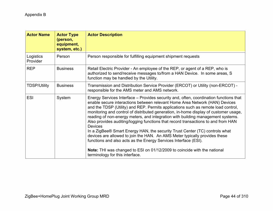
Appendix B
ZigBee+HomePlug Joint Working Group MRD Page 44 of 310
Actor Name Actor Type (person, equipment, system, etc.)
Actor Description
Logistics Provider
Person Person responsible for fulfilling equipment shipment requests
REP Business Retail Electric Provider An employee of the REP, or agent of a REP, who is authorized to send/receive messages to/from a HAN Device. In some areas, S function may be handled by the Utility.
TDSP/Utility Business Transmission and Distribution Service Provider (ERCOT) or Utility (nonERCOT) responsible for the AMS meter and AMS network.
ESI System Energy Services Interface – Provides security and, often, coordination functions that enable secure interactions between relevant Home Area Network (HAN) Devices and the TDSP (Utility) and REP. Permits applications such as remote load control, monitoring and control of distributed generation, inhome display of customer usage, reading of nonenergy meters, and integration with building management systems. Also provides auditing/logging functions that record transactions to and from HAN Devices In a ZigBee® Smart Energy HAN, the security Trust Center (TC) controls what devices are allowed to join the HAN. An AMS Meter typically provides these functions and also acts as the Energy Services Interface (ESI).
Note: THI was changed to ESI on 01/12/2009 to coincide with the national terminology for this interface.
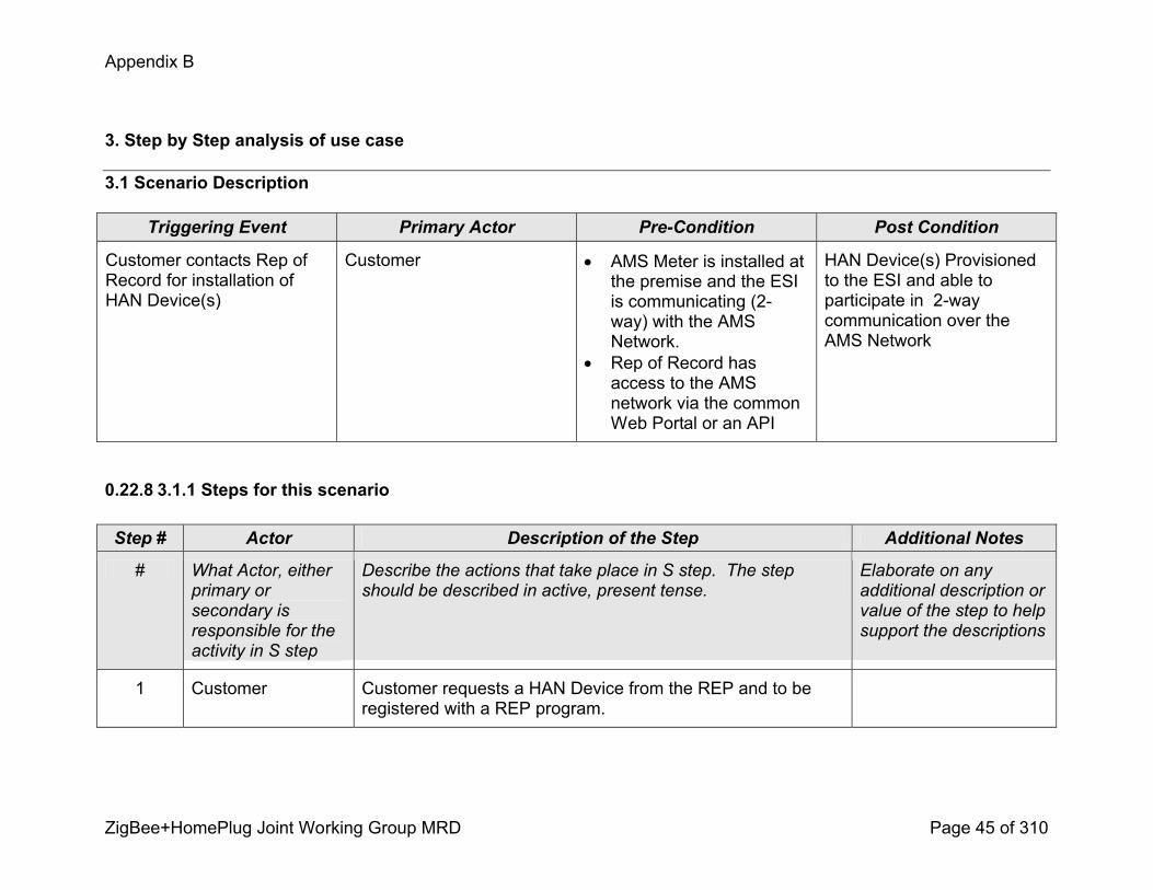
Appendix B
ZigBee+HomePlug Joint Working Group MRD Page 45 of 310
3. Step by Step analysis of use case
3.1 Scenario Description
Triggering Event Primary Actor PreCondition Post Condition
Customer contacts Rep of Record for installation of HAN Device(s)
Customer ! AMS Meter is installed at the premise and the ESI is communicating (2way) with the AMS Network.
! Rep of Record has access to the AMS network via the common Web Portal or an API
HAN Device(s) Provisioned to the ESI and able to participate in 2way communication over the AMS Network
0.22.8 3.1.1 Steps for this scenario
Step # Actor Description of the Step Additional Notes
# What Actor, either primary or secondary is responsible for the activity in S step
Describe the actions that take place in S step. The step should be described in active, present tense.
Elaborate on any additional description or value of the step to help support the descriptions
1 Customer Customer requests a HAN Device from the REP and to be registered with a REP program.
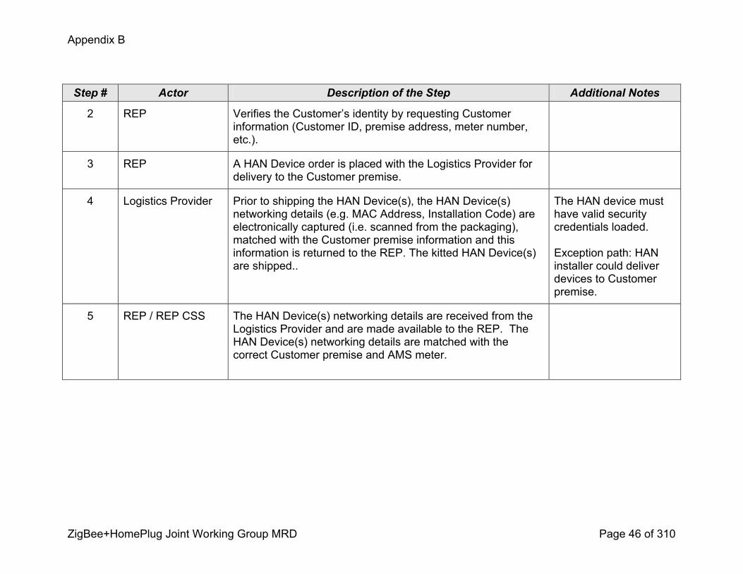
Appendix B
ZigBee+HomePlug Joint Working Group MRD Page 46 of 310
Step # Actor Description of the Step Additional Notes
2 REP Verifies the Customer’s identity by requesting Customer information (Customer ID, premise address, meter number, etc.).
3 REP A HAN Device order is placed with the Logistics Provider for delivery to the Customer premise.
4 Logistics Provider Prior to shipping the HAN Device(s), the HAN Device(s) networking details (e.g. MAC Address, Installation Code) are electronically captured (i.e. scanned from the packaging), matched with the Customer premise information and this information is returned to the REP. The kitted HAN Device(s) are shipped..
The HAN device must have valid security credentials loaded.
Exception path: HAN installer could deliver devices to Customer premise.
5 REP / REP CSS The HAN Device(s) networking details are received from the Logistics Provider and are made available to the REP. The HAN Device(s) networking details are matched with the correct Customer premise and AMS meter.
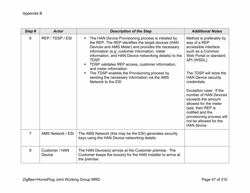
Appendix B
ZigBee+HomePlug Joint Working Group MRD Page 47 of 310
Step # Actor Description of the Step Additional Notes
6 REP / TDSP / ESI ! The HAN Device Provisioning process is initiated bythe REP. The REP identifies the target devices (HAN Devices and AMS Meter) and provides the necessary information (e.g. customer information, meter information, and HAN Device networking details) to the TDSP
! TDSP validates REP access, customer information, and meter information.
! The TDSP enables the Provisioning process by sending the necessary information via the AMS Network to the ESI
Method is preferably by way of a REP accessible interface such as a Common Web Portal or standard API (WSDL).
The TDSP will store the HAN Device security credentials.
Exception case: If the number of HAN Devices exceeds the amount allowed for the meter type, then REP is notified and the provisioning process will not be allowed for the HAN device
7 AMS Network / ESI The AMS Network (this may be the ESI) generates security keys using the HAN Device networking details.
8 Customer / HAN Device
The HAN Device(s) arrives at the Customer premise. The Customer keeps the box(es) for the HAN Installer to arrive at the premise.

Appendix B
ZigBee+HomePlug Joint Working Group MRD Page 48 of 310
Step # Actor Description of the Step Additional Notes
9 HAN Installer / HAN Device
All the HAN Installer has to do to provision the HAN Device to the ESI is simply power on the HAN Device and initiate the joining process per the HAN Device manufacturer’s instructions.
Different HAN devices may employ different methods to initiate the joining process such as simply powering the device on or by pushing one or multiple buttons.
10 HAN Device / ESI Upon initiating the join process, the HAN Device will scan for ESIs to join. It is possible the HAN Device may be in range of more than one ESI and will attempt to join the first ESI it finds. However, only the ESI that has the correct security credentials for this specific HAN Device will allow the HAN Device to join.
Exception: If an ESI receives a request from a HAN Device it does not recognize it will not allow the HAN Device to join to it. The HAN Device will try other ESIs until it is allowed to complete the join process.
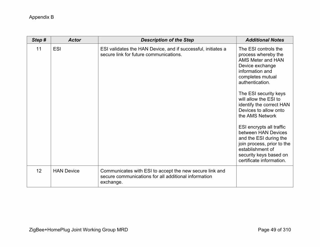
Appendix B
ZigBee+HomePlug Joint Working Group MRD Page 49 of 310
Step # Actor Description of the Step Additional Notes
11 ESI ESI validates the HAN Device, and if successful, initiates a secure link for future communications.
The ESI controls the process whereby the AMS Meter and HAN Device exchange information and completes mutual authentication.
The ESI security keys will allow the ESI to identify the correct HAN Devices to allow onto the AMS Network
ESI encrypts all traffic between HAN Devices and the ESI during the join process, prior to the establishment of security keys based on certificate information.
12 HAN Device Communicates with ESI to accept the new secure link and secure communications for all additional information exchange.

Appendix B
ZigBee+HomePlug Joint Working Group MRD Page 50 of 310
Step # Actor Description of the Step Additional Notes
13 HAN Device / Customer
The HAN Device will provide feedback to the customer on successful or unsuccessful Provisioning.
If unsuccessful, the HAN Device should provide an appropriate feedback to the Customer.
14 ESI ESI communicates, to the common web portal, the successful provisioning of a HAN device
15 Common Web Portal
The common web portal updates the list of HAN devices provisioned to the ESI
.
Completion of the Provisioning process and the update in the Common Web Portal is desired in less than one minute
16 REP / Common Web Portal
Once the Common Web Portal includes the new Provisioned HAN Device in the list of Provisioned HAN Devices, the REP can acknowledge the update and complete the Registration of the HAN Device with the appropriate REP program in the REP CSS.
Note: Registration is outside the scope of this use case.
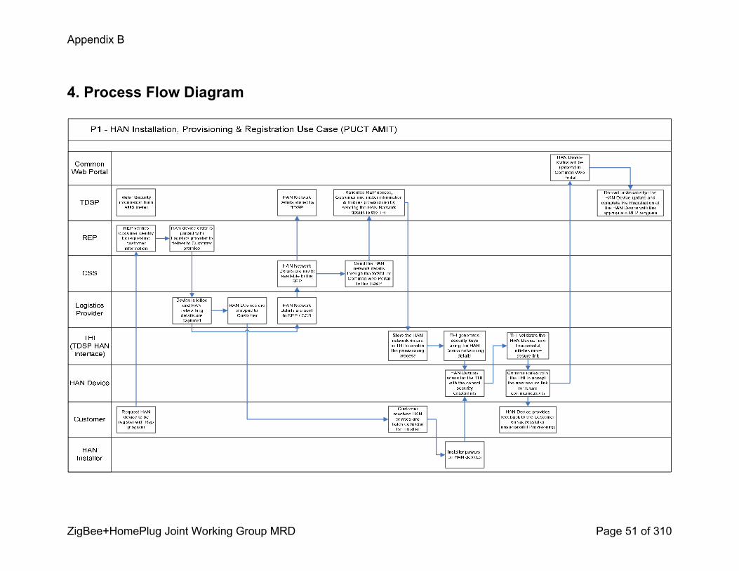
Appendix B
ZigBee+HomePlug Joint Working Group MRD Page 51 of 310
4. Process Flow Diagram

Appendix B
ZigBee+HomePlug Joint Working Group MRD Page 52 of 310
HAN Installation and ProvisioningP2 –Utility HAN Devices – Self Install
120808

Appendix B
ZigBee+HomePlug Joint Working Group MRD Page 53 of 310
0. Use Case FrameworkThis use case for HAN Device installation and provisioning is based on the framework below:
Indirect Delivery
P3 Retail offthe shelf HAN Devices +
Professional Install
P4 Retail offthe shelf HAN Devices + Self Install
Direct Delivery
P1 Utility HAN Devices + Professional Install
P2 Utility HAN Devices + Self Install
Professional Install Self Install
1. Use Case Description
1.1 Use Case TitleUtility HAN Devices – Self Install
1.2 Use Case SummaryThe process of provisioning a HAN device from installing to Provisioning and Registering a Utility/REP ordered HAN device through the Energy Services Interface (ESI) over an AMI Network and to the Customer Service System (CSS).

Appendix B
ZigBee+HomePlug Joint Working Group MRD Page 54 of 310
1.3 Use Case Detailed Narrative
Once the AMI Network and AMI Meter with HAN communication capability is installed and provisioned at the premise, the Customer is eligible for HAN Device(s) installation. The Customer triggers the fulfillment process by calling their Utility/REP who will enter the necessary information into the CSS. The Utility/REP will initiate a HAN Device(s) fulfillment request to the Logistics Provider (Internal or 3rd party). HAN Device networking details (MAC address, Installation Code) are electronically captured prior to the HAN Device(s) being shipped to the Customer premise. The relevant HAN Device networking details are communicated by the Logistics Provider back to the Utility/REP where they are combined with the AMI Meter information and the Customer information in the CSS.
The HAN Device provisioning process is initiated by the Utility/REP through the CSS. This request is communicated by way of an API (WSDL or Web Service Definition Language) over the AMI Network to the ESI. The mechanism used in this use case for joining a HAN Device to the ESI is the Smart Energy “unsecured rejoin” procedure (see Smart Energy Profile r14, section 5.4.2.1). The AMI Meter must be preconfigured with security keys derived from the HAN Device(s) networking details before the HAN Device(s) attempts to join the AMI Meter’s Smart Energy HAN communication link. The appropriate HAN Device networking details will be submitted to the correct AMI Meter through the ESI via the AMI Network from the CSS.
The HAN Device(s) arrive at the Customer premise and the AMI Meter is prepared to allow the appropriate HAN Device(s) to join. All the Customer has to do to register the HAN Device to a Utility/REP program is to simply power the HAN Device and follow the HAN Device manufacturer’s instructions. The HAN Device will automatically perform a secure transaction to join to its preconfigured AMI Meter. Following a successful join, the HAN Device is considered provisioned and will communicate through the ESI and over the AMI Network to the CSS to complete registration of the HAN Device to the appropriate Utility/REP program. Upon successful registration, the CSS will send an acknowledgement to the HAN Device over the AMI Network through the ESI to complete the installing, provisioning and registration process for the HAN Device.
1.4 Business Rules and AssumptionsAssumptions
! This P2 use case is typically for Residential Customers only! AMI Meter is installed at the premise and is connected to a functional AMI Communications network (i.e. the AMI Meter is provisioned).! In markets with REP’s or other 3rd party access rights, the AMI Network has an API that is accessible to REP’s or third parties to send
messages and commands! HAN Application is using the Smart Energy application including the use of Certificates and Certificate Based Key Establishment (CBKE)! The physical HAN layer is secure! All HAN Devices (including meters) must come from the manufacturer with a valid security certificate loaded, that was issued by an
authorized Certificate Authority as required
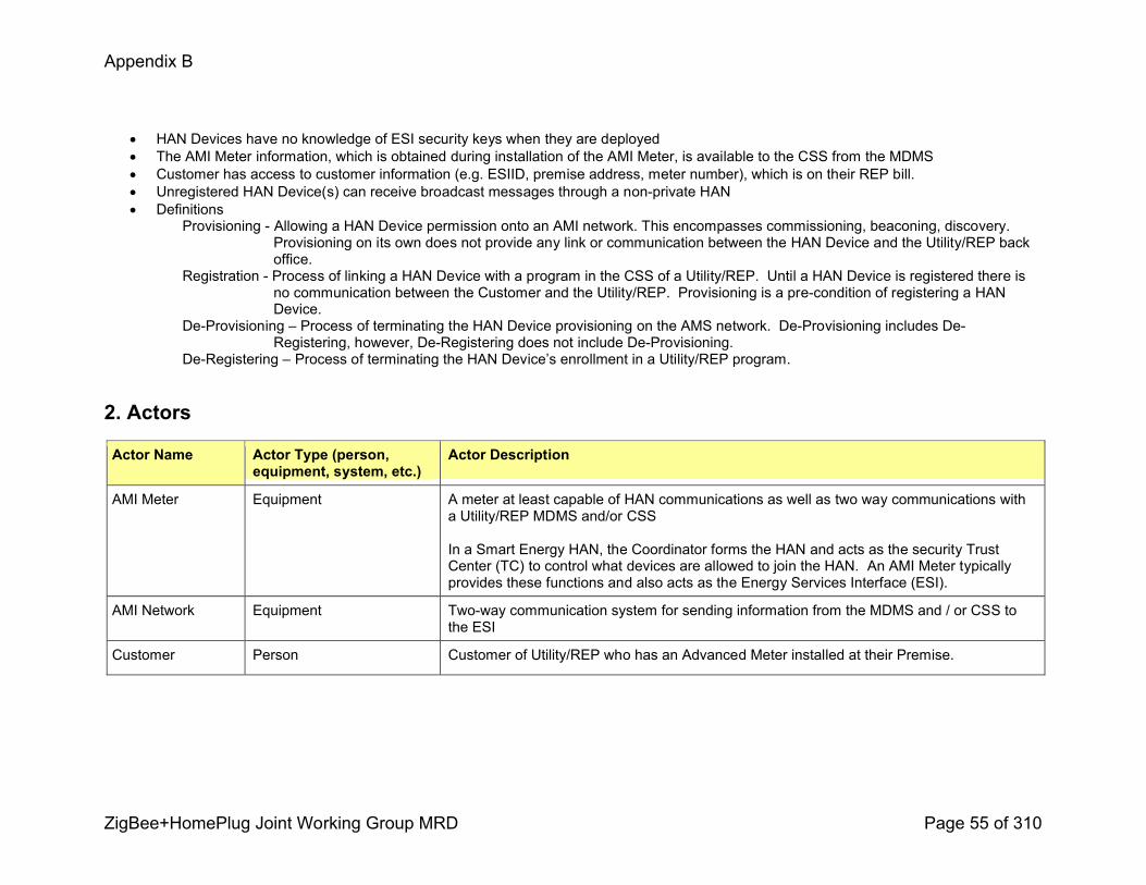
Appendix B
ZigBee+HomePlug Joint Working Group MRD Page 55 of 310
! HAN Devices have no knowledge of ESI security keys when they are deployed! The AMI Meter information, which is obtained during installation of the AMI Meter, is available to the CSS from the MDMS! Customer has access to customer information (e.g. ESIID, premise address, meter number), which is on their REP bill.! Unregistered HAN Device(s) can receive broadcast messages through a nonprivate HAN ! Definitions
Provisioning Allowing a HAN Device permission onto an AMI network. This encompasses commissioning, beaconing, discovery. Provisioning on its own does not provide any link or communication between the HAN Device and the Utility/REP back office.
Registration Process of linking a HAN Device with a program in the CSS of a Utility/REP. Until a HAN Device is registered there is no communication between the Customer and the Utility/REP. Provisioning is a precondition of registering a HAN Device.
DeProvisioning – Process of terminating the HAN Device provisioning on the AMS network. DeProvisioning includes DeRegistering, however, DeRegistering does not include DeProvisioning.
DeRegistering – Process of terminating the HAN Device’s enrollment in a Utility/REP program.
2. Actors
Actor Name Actor Type (person, equipment, system, etc.)
Actor Description
AMI Meter Equipment A meter at least capable of HAN communications as well as two way communications with a Utility/REP MDMS and/or CSS
In a Smart Energy HAN, the Coordinator forms the HAN and acts as the security Trust Center (TC) to control what devices are allowed to join the HAN. An AMI Meter typically provides these functions and also acts as the Energy Services Interface (ESI).
AMI Network Equipment Twoway communication system for sending information from the MDMS and / or CSS to the ESI
Customer Person Customer of Utility/REP who has an Advanced Meter installed at their Premise.

Appendix B
ZigBee+HomePlug Joint Working Group MRD Page 56 of 310
Actor Name Actor Type (person, equipment, system, etc.)
Actor Description
CSS System Customer Service System – A Utility/REP owned system or systems (e.g. system used by the call center) that provides Utility/REP employees the ability to view Consumerspecific information regarding billing, tariffs, programs, metering, interval usage, etc. and includes functionality that will establish and maintain HAN communications between the Utility/REP and HAN Device(s) over the ESI.
ESI System Provides security and, often, coordination functions that enable secure interactions between relevant Home Area Network (HAN) Devices and the TDSP (Utility) and Utility/REP. Permits applications such as remote load control, monitoring and control of distributed generation, inhome display of customer usage, reading of nonenergy meters, and integration with building management systems. Also provides auditing/logging functions that record transactions to and from HAN Devices.
HAN Devices Equipment Equipment owned by the Customer capable of twoway communication with the AMI Meter
Logistics Provider Person Person responsible for fulfilling equipment shipment requests
MDMS System Meter Data Management System owned by the TDSP/ Utility.
TDSP/Utility Business Transmission and Distribution Service Provider (ERCOT) or Utility (nonERCOT) responsible for the AMI Meter, AMI Network and MDMS.
Utility/REP Business Retail Electric Provider An employee of the Utility/REP, or agent of a Utility/REP, who is authorized to send/receive messages to/from a HAN Device

Appendix B
ZigBee+HomePlug Joint Working Group MRD Page 57 of 310
3. Step by Step analysis of use case
3.1 Scenario Description
Triggering Event Primary Actor PreCondition Post Condition
Customer contacts Utility/REP for installation of HAN Device(s)
Customer AMI Meter installed at the premise and provisioned by the TDSP/Utility
HAN Device(s) provisioned to the ESI and registered with a Utility/REP program through twoway communication over the AMI Network
0.22.9 3.1.1 Steps for this scenario
Step # Actor Description of the Step Additional Notes# What Actor, either primary or
secondary is responsible for the activity in this step
Describe the actions that take place in this step. The step should be described in active, present tense.
Elaborate on any additional description or value of the step to help support the descriptions
1 Customer Customer requests a HAN Device from the Utility/REP.
2 Utility/REP Verifies the Customer’s identity by requesting Customer information (Customer ID, premise address, etc.).
3 Utility/REP A HAN Device order is placed with the Logistics Provider for delivery to the Customer premise.
4 Logistics Provider Prior to shipping the HAN Device(s), the HAN Device(s) networking details (MAC Address, Installation Code) are electronically captured (i.e. scanned from the packaging), matched with the Customer premise information and this information is returned to the Utility/REP. The kitted devices are shipped directly to the Customer.
The HAN Device must have a valid security certificate loaded.

Appendix B
ZigBee+HomePlug Joint Working Group MRD Page 58 of 310
Step # Actor Description of the Step Additional Notes
5 CSS The HAN Device(s) networking details are received from the Logistics Provider and are stored in the CSS. The HAN Device(s) networking details are matched with the correct Customer premise and AMI Meter information.
6 Utility/REP / CSS The HAN Device provisioning process is initiated by the Utility/REP through the ESI by way of an API (WSDL).
The target devices (i.e., HAN Device(s) and AMI Meter) are identified and addressed using customer account information, the meter information, and the HAN Device networking details.
The HAN Device networking details are sent from the CSS to the ESI via the AMI Network.
The ESI computes the security keys from the HAN networking details.
The ESI security keys will:1. allow the ESI to identify the correct HAN Devices to allow onto the
AMI Meter’s network,2. encrypt all traffic between HAN Devices and the AMI Meter during
the join process, prior to the establishment of security keys based on certificate information.
The intention is for the Smart Energy Profile ‘unsecured rejoin’ procedure to be utilized here. This does not require the AMI Meter to be placed in ‘open join’ mode, nor does it require shared network or security keys among meters or devices.
‘Unsecured’ does not mean this mechanism violates security best practices, it simply means knowledge of the network key is not required by the HAN Device. Relaxing this requirement does not compromise security, since authentication is performed via security certificates, NOT the network key.
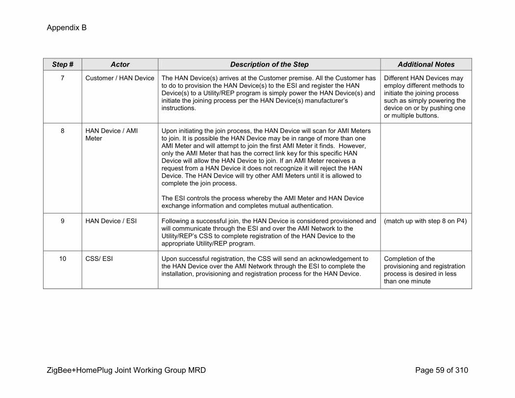
Appendix B
ZigBee+HomePlug Joint Working Group MRD Page 59 of 310
Step # Actor Description of the Step Additional Notes
7 Customer / HAN Device The HAN Device(s) arrives at the Customer premise. All the Customer has to do to provision the HAN Device(s) to the ESI and register the HAN Device(s) to a Utility/REP program is simply power the HAN Device(s) and initiate the joining process per the HAN Device(s) manufacturer’s instructions.
Different HAN Devices may employ different methods to initiate the joining process such as simply powering the device on or by pushing one or multiple buttons.
8 HAN Device / AMI Meter
Upon initiating the join process, the HAN Device will scan for AMI Meters to join. It is possible the HAN Device may be in range of more than one AMI Meter and will attempt to join the first AMI Meter it finds. However, only the AMI Meter that has the correct link key for this specific HAN Device will allow the HAN Device to join. If an AMI Meter receives a request from a HAN Device it does not recognize it will reject the HAN Device. The HAN Device will try other AMI Meters until it is allowed to complete the join process.
The ESI controls the process whereby the AMI Meter and HAN Device exchange information and completes mutual authentication.
9 HAN Device / ESI Following a successful join, the HAN Device is considered provisioned and will communicate through the ESI and over the AMI Network to the Utility/REP’s CSS to complete registration of the HAN Device to the appropriate Utility/REP program.
(match up with step 8 on P4)
10 CSS/ ESI Upon successful registration, the CSS will send an acknowledgement to the HAN Device over the AMI Network through the ESI to complete the installation, provisioning and registration process for the HAN Device.
Completion of the provisioning and registration process is desired in less than one minute
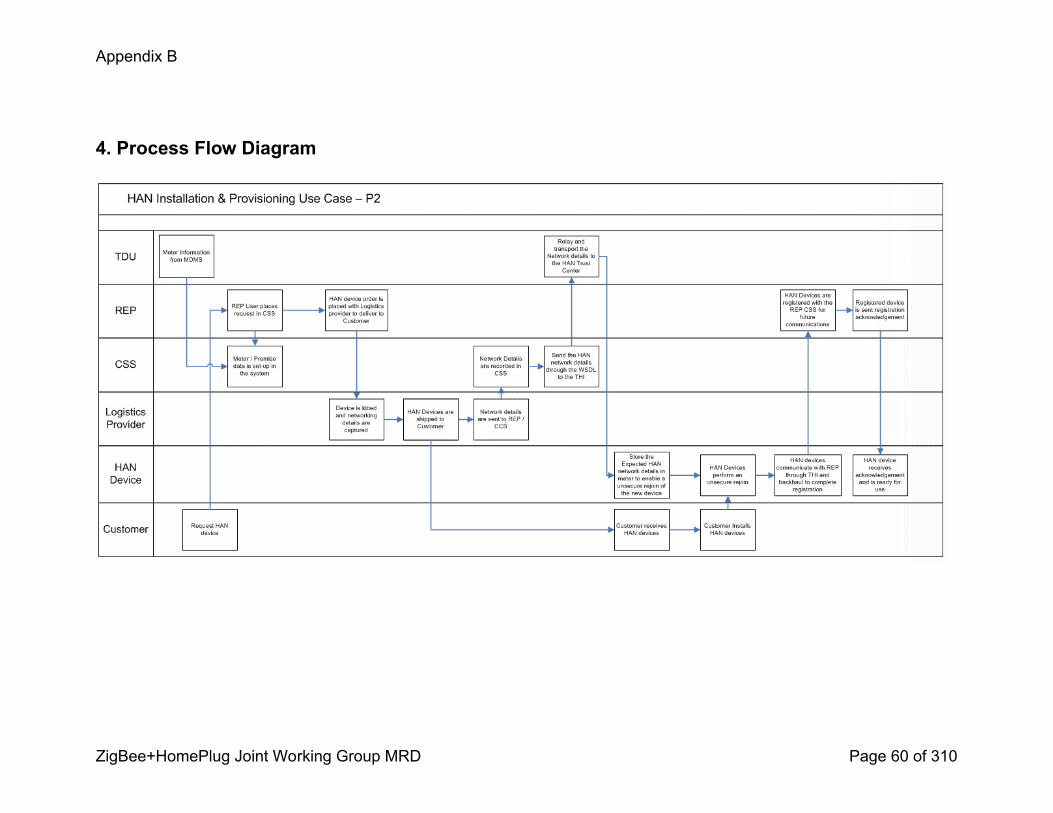
Appendix B
ZigBee+HomePlug Joint Working Group MRD Page 60 of 310
4. Process Flow Diagram

Appendix B
ZigBee+HomePlug Joint Working Group MRD Page 61 of 310
HAN Installation, Provisioning, and Registration (optional)P4 – Retail OffTheShelf HAN Devices – Self Install
120808rev. 121108

Appendix B
ZigBee+HomePlug Joint Working Group MRD Page 62 of 310
0. Use Case FrameworkThis use case for HAN Device installation and provisioning is based on the framework below:
Indirect Delivery
P3 Retail offthe shelf HAN Devices +
Professional Install
P4 Retail offthe shelf HAN Devices + Self Install
Direct Delivery
P1 Utility / REP ordered HAN Devices +
Professional Install
P2 Utility / REP ordered HAN Devices +
Self Install
Professional Install Self Install
1. Use Case Description
1.1 Use Case TitleRetail OffTheShelf HAN Devices + Self Install
1.2 Use Case SummaryThe process of provisioning a retail purchased HAN device from installing to Provisioning and optionally Registering a HAN device through an Energy Services Interface (ESI) over an AMI Network and to the Customer Service System (CSS). The Customer may only want to Provision the HAN Device to receive AMI Meter information and may choose to Register or not Register the HAN Device with a particular Utility / REP program

Appendix B
ZigBee+HomePlug Joint Working Group MRD Page 63 of 310
1.3 Use Case Detailed NarrativeThe use case is triggered by the Customer acquiring a HAN Device from an indirect source [i.e. not from the Utility or REP] and wanting to install it in his/her home.
An AMI Meter and AMI Network must be installed and operational at the Customer premise as a precondition for this use case. AMI Meter and premise information must be captured during AMI Meter installation by Utility / TDU for use in Provisioning a HAN Device. Specifically the AMI Meter identification and the AMI Meter’s HAN communications address [e.g. ZigBee MAC address] is needed to address the meter through the ESI. The AMI Meter at time of deployment is assumed to have no precommissioning of HAN Device networking details. The HAN Device is assumed to have no knowledge of security key[s] for the AMI Meter HAN communications link.
To begin the installation process, the Customer must identify themselves to their Utility or REP with their unique Customer id [e.g. Customer account, premise address, etc]. This information given to the Utility or REP must uniquely identify the Customer, the Customer premise and the specific AMI Meter for that premise. The Customer must provide the necessary HAN Device networking details [e.g. MAC address, Installation Code] to the Utility or REP. These HAN Device networking details will be used by the MDMS / AMI Network to Provision the HAN Device to the AMI Meter and additionally by the CSS if the Customer wants to Register the HAN Device for Utility or REP programs. The Customer has several ways to contact the Utility or REP to begin the installation process including:
1. logging into Utility/REP web site and loading the HAN device details2. phone—live agent or IVR; the exception path for IVR would lead to a live agent3. logging into a third party website, with a national database for registration4. intiating the process through an appropriate retail channel
The HAN Device Provisioning process will be completed in one of two ways depending upon what the Customer wants to do with the HAN Device. If the Customer only wants the HAN Device to receive information from the AMI Meter, the Customer will contact their Utility/REP to begin the Provisioning process. This process will be complete upon the HAN Device being successfully Provisioned to the customer’s AMI Meter. If the Customer wants to Register the HAN Device for a particular Utility / REP program, the Customer will contact their Utility / REP to begin the Provisioning and Registration process (Use Case P4b). Once the Utility or REP receives the request from the Customer, the request is communicated by way of an API (WSDL or Web Service Definition Language) over the AMI Network to the ESI at the Customer’s AMI Meter. The mechanism used for joining a HAN Device to the ESI is the Smart Energy “unsecured rejoin” procedure (see ZigBee Smart Energy Profile r14, section 5.4.2.1). The AMI Meter must be preconfigured with security keys derived from installation codes of the HAN Device before the HAN Device can attempt to join the AMI Meter’s ZigBee Smart Energy HAN communication link. The appropriate HAN Device security keys will be submitted to the correct AMI Meter through the ESI via the AMI Network from the appropriate utility back office system [e.g. MDMS or CSS].
Once the AMI Meter is prepared to allow the appropriate HAN Devices to join, the Customer simply powers the HAN Device and follows the HAN Device manufacturer’s instructions. The HAN device will perform a secure transaction to join to its preconfigured AMI Meter. Following a successful join, the HAN Device is considered Provisioned and the HAN Device will communicate through the ESI to the AMI meter. An extensionof this use case has the HAN Device continuing with the Registration process through the ESI over the AMI Network to the CSS to complete
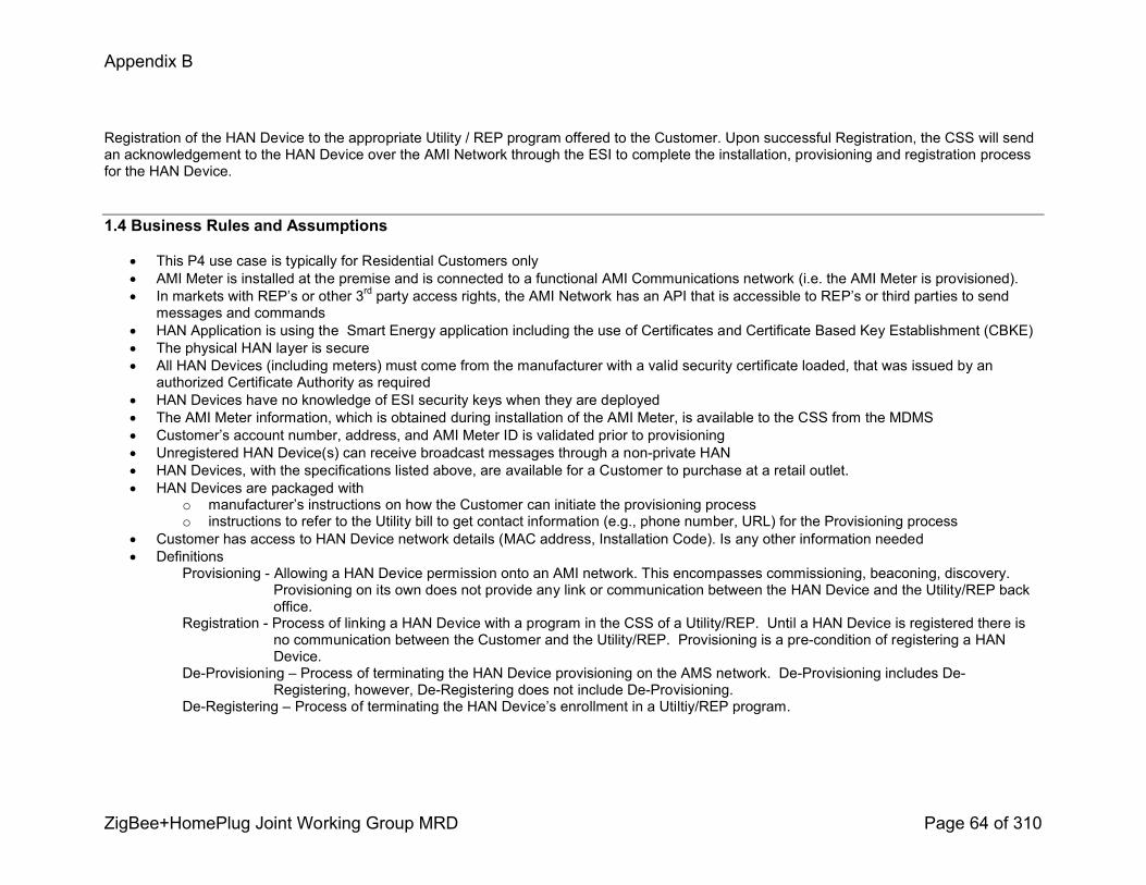
Appendix B
ZigBee+HomePlug Joint Working Group MRD Page 64 of 310
Registration of the HAN Device to the appropriate Utility / REP program offered to the Customer. Upon successful Registration, the CSS will send an acknowledgement to the HAN Device over the AMI Network through the ESI to complete the installation, provisioning and registration process for the HAN Device.
1.4 Business Rules and Assumptions
! This P4 use case is typically for Residential Customers only! AMI Meter is installed at the premise and is connected to a functional AMI Communications network (i.e. the AMI Meter is provisioned).! In markets with REP’s or other 3rd party access rights, the AMI Network has an API that is accessible to REP’s or third parties to send
messages and commands! HAN Application is using the Smart Energy application including the use of Certificates and Certificate Based Key Establishment (CBKE)! The physical HAN layer is secure! All HAN Devices (including meters) must come from the manufacturer with a valid security certificate loaded, that was issued by an
authorized Certificate Authority as required! HAN Devices have no knowledge of ESI security keys when they are deployed! The AMI Meter information, which is obtained during installation of the AMI Meter, is available to the CSS from the MDMS! Customer’s account number, address, and AMI Meter ID is validated prior to provisioning! Unregistered HAN Device(s) can receive broadcast messages through a nonprivate HAN ! HAN Devices, with the specifications listed above, are available for a Customer to purchase at a retail outlet. ! HAN Devices are packaged with
o manufacturer’s instructions on how the Customer can initiate the provisioning processo instructions to refer to the Utility bill to get contact information (e.g., phone number, URL) for the Provisioning process
! Customer has access to HAN Device network details (MAC address, Installation Code). Is any other information needed! Definitions
Provisioning Allowing a HAN Device permission onto an AMI network. This encompasses commissioning, beaconing, discovery. Provisioning on its own does not provide any link or communication between the HAN Device and the Utility/REP back office.
Registration Process of linking a HAN Device with a program in the CSS of a Utility/REP. Until a HAN Device is registered there is no communication between the Customer and the Utility/REP. Provisioning is a precondition of registering a HAN Device.
DeProvisioning – Process of terminating the HAN Device provisioning on the AMS network. DeProvisioning includes DeRegistering, however, DeRegistering does not include DeProvisioning.
DeRegistering – Process of terminating the HAN Device’s enrollment in a Utiltiy/REP program.
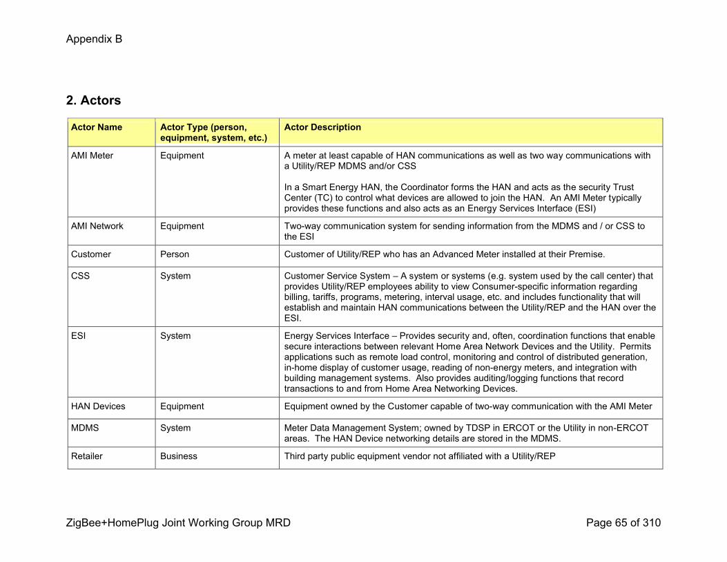
Appendix B
ZigBee+HomePlug Joint Working Group MRD Page 65 of 310
2. Actors
Actor Name Actor Type (person, equipment, system, etc.)
Actor Description
AMI Meter Equipment A meter at least capable of HAN communications as well as two way communications with a Utility/REP MDMS and/or CSS
In a Smart Energy HAN, the Coordinator forms the HAN and acts as the security Trust Center (TC) to control what devices are allowed to join the HAN. An AMI Meter typically provides these functions and also acts as an Energy Services Interface (ESI)
AMI Network Equipment Twoway communication system for sending information from the MDMS and / or CSS to the ESI
Customer Person Customer of Utility/REP who has an Advanced Meter installed at their Premise.
CSS System Customer Service System – A system or systems (e.g. system used by the call center) that provides Utility/REP employees ability to view Consumerspecific information regarding billing, tariffs, programs, metering, interval usage, etc. and includes functionality that will establish and maintain HAN communications between the Utility/REP and the HAN over the ESI.
ESI System Energy Services Interface – Provides security and, often, coordination functions that enable secure interactions between relevant Home Area Network Devices and the Utility. Permits applications such as remote load control, monitoring and control of distributed generation, inhome display of customer usage, reading of nonenergy meters, and integration with building management systems. Also provides auditing/logging functions that record transactions to and from Home Area Networking Devices.
HAN Devices Equipment Equipment owned by the Customer capable of twoway communication with the AMI Meter
MDMS System Meter Data Management System; owned by TDSP in ERCOT or the Utility in nonERCOT areas. The HAN Device networking details are stored in the MDMS.
Retailer Business Third party public equipment vendor not affiliated with a Utility/REP
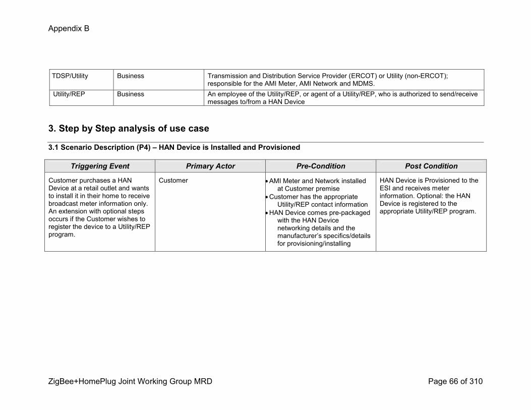
Appendix B
ZigBee+HomePlug Joint Working Group MRD Page 66 of 310
TDSP/Utility Business Transmission and Distribution Service Provider (ERCOT) or Utility (nonERCOT); responsible for the AMI Meter, AMI Network and MDMS.
Utility/REP Business An employee of the Utility/REP, or agent of a Utility/REP, who is authorized to send/receive messages to/from a HAN Device
3. Step by Step analysis of use case
3.1 Scenario Description (P4) – HAN Device is Installed and Provisioned
Triggering Event Primary Actor PreCondition Post Condition
Customer purchases a HAN Device at a retail outlet and wants to install it in their home to receive broadcast meter information only. An extension with optional steps occurs if the Customer wishes to register the device to a Utility/REP program.
Customer !AMI Meter and Network installed at Customer premise
!Customer has the appropriate Utility/REP contact information
!HAN Device comes prepackaged with the HAN Device networking details and the manufacturer’s specifics/details for provisioning/installing
HAN Device is Provisioned to the ESI and receives meter information. Optional: the HAN Device is registered to the appropriate Utility/REP program.
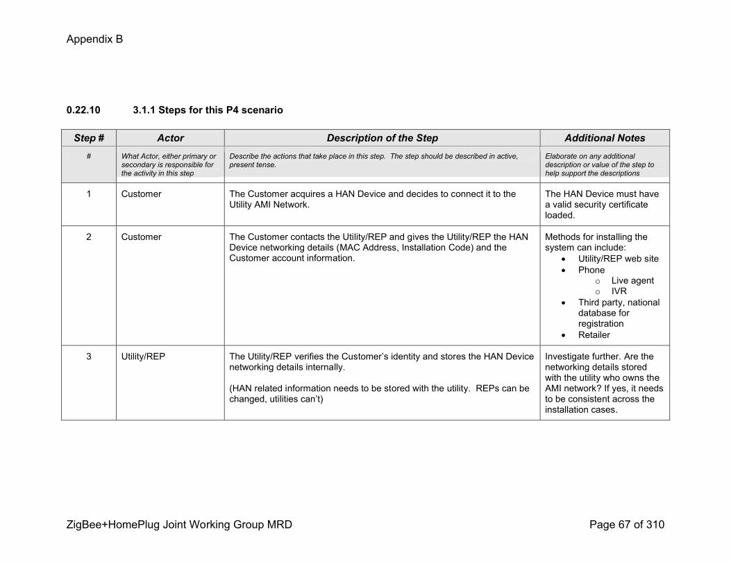
Appendix B
ZigBee+HomePlug Joint Working Group MRD Page 67 of 310
0.22.10 3.1.1 Steps for this P4 scenario
Step # Actor Description of the Step Additional Notes# What Actor, either primary or
secondary is responsible for the activity in this step
Describe the actions that take place in this step. The step should be described in active, present tense.
Elaborate on any additional description or value of the step to help support the descriptions
1 Customer The Customer acquires a HAN Device and decides to connect it to the Utility AMI Network.
The HAN Device must have a valid security certificate loaded.
2 Customer The Customer contacts the Utility/REP and gives the Utility/REP the HAN Device networking details (MAC Address, Installation Code) and the Customer account information.
Methods for installing the system can include:
! Utility/REP web site! Phone
o Live agento IVR
! Third party, national database for registration
! Retailer
3 Utility/REP The Utility/REP verifies the Customer’s identity and stores the HAN Device networking details internally.
(HAN related information needs to be stored with the utility. REPs can be changed, utilities can’t)
Investigate further. Are the networking details stored with the utility who owns the AMI network? If yes, it needs to be consistent across the installation cases.

Appendix B
ZigBee+HomePlug Joint Working Group MRD Page 68 of 310
Step # Actor Description of the Step Additional Notes
4 TDSP/Utility The HAN Device provisioning process is initiated by the Utility/REP through the ESI.
The target devices (i.e., HAN Device(s) and AMI Meter) are identified and addressed using customer account information, the meter information, and the HAN Device networking details.
The HAN Device networking details are sent via the AMI Network.
Method could be by way of an API (WSDL)
Details may reside in the CSS
This transaction may take place from the CSS to the ESI
5 TDSP/Utility? The Utility computes the security keys from the HAN networking details.
The ESI security keys will allow the Utility to identify the correct HAN Devices to allow onto the AMI Meter’s network,
Encrypt all traffic between HAN Devices and the AMI Meter during the join process, prior to the establishment of security keys based on certificate information.
6 Customer The Customer simply powers the HAN Device and initiates the joining process per the HAN Device manufacturer’s instructions.
Different HAN Devices may employ different methods to initiate the joining process such as simply powering the device on or by pushing one or multiple buttons.

Appendix B
ZigBee+HomePlug Joint Working Group MRD Page 69 of 310
Step # Actor Description of the Step Additional Notes
7 HAN Device / AMI Meter
Upon initiating the join process, the HAN Device will scan for AMI Meters to join. It is possible the HAN Device may be in range of more than one AMI Meter and will attempt to join the first AMI Meter it finds. However, only the AMI Meter that has the correct security key for this specific HAN Device will allow the HAN Device to join. If an AMI Meter receives a request from a HAN Device it does not recognize it will reject the HAN Device. The HAN device will try other AMI Meters until it is allowed to complete the join process.
The ESI controls the process whereby the AMI Meter and HAN Device exchange information and completes mutual authentication.
8 HAN Device / ESI Following a successful join, the HAN Device is considered provisioned and will communicate with the AMI meter through the ESI and will provide feedback to the customer on successful (or unsuccessful) provisioning.
Optional: Following a successful join, the HAN Device is considered Provisioned. The HAN Device could then communicate with the AMI meter through the ESI and over the AMI Network to the Utility/REP’s CSS to complete the Registration of the HAN Device to the appropriate Utility/REP program offered to the Customer.
9(Optional)
CSS/ ESI Upon successful Registration, the CSS will send an acknowledgement to the HAN Device over the AMI Network through the ESI to complete the installation, Provisioning, and Registration process for the HAN Device.
Completion of the Provisioning and Registration process is desired in less than 1 minute.
Appendix B
ZigBee+HomePlug Joint Working Group MRD Page 70 of 310
Home Area Network Use Cases
Prepay
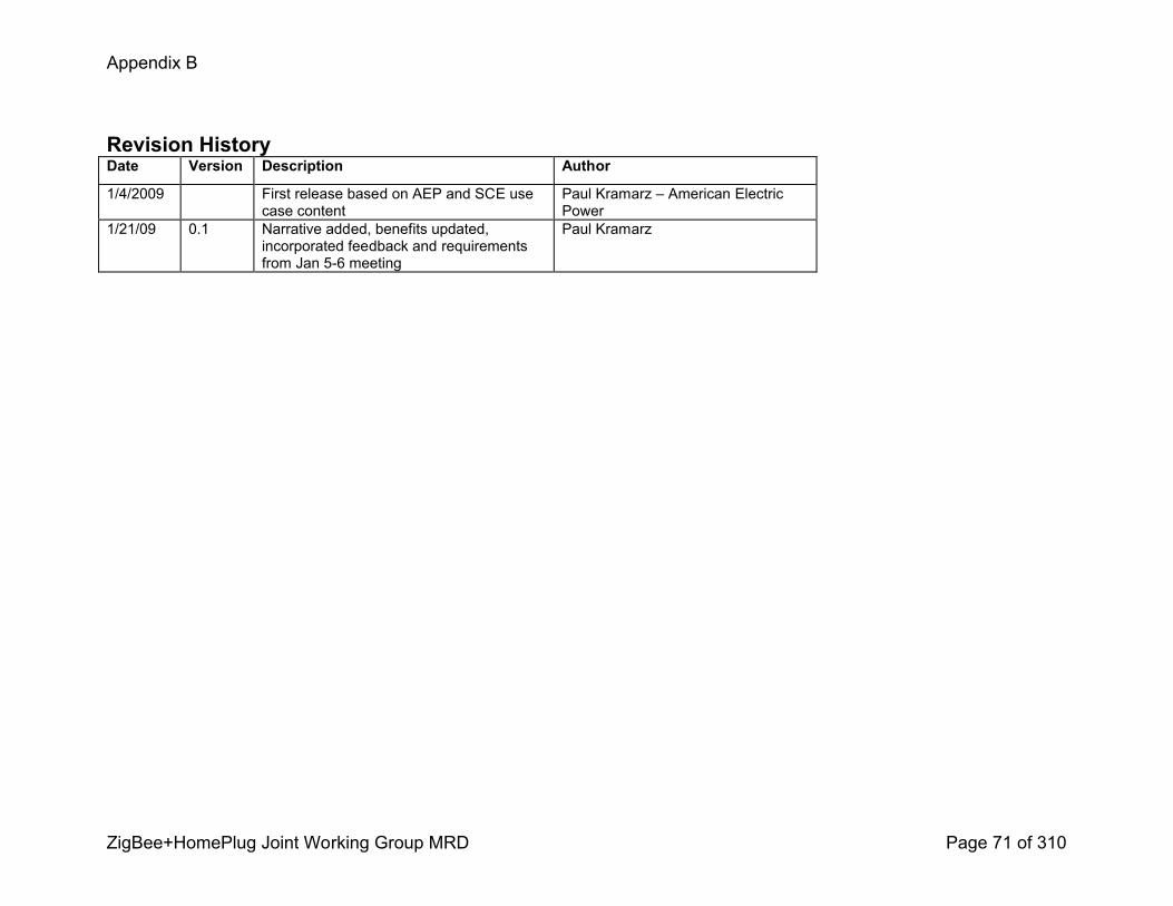
Appendix B
ZigBee+HomePlug Joint Working Group MRD Page 71 of 310
Revision HistoryDate Version Description Author
1/4/2009 First release based on AEP and SCE use case content
Paul Kramarz – American Electric Power
1/21/09 0.1 Narrative added, benefits updated, incorporated feedback and requirements from Jan 56 meeting
Paul Kramarz

Appendix B
ZigBee+HomePlug Joint Working Group MRD Page 72 of 310
1.1 Use Case TitleThe Customer prepays for energy usage.
1.2 Use Case SummaryA customer’s interest is to receive electrical service with low or no start up cost. Postpay and prepaid electrical service could include a required deposit and potentially additional equipment. A utility’s interest is to have deposits proportional to the amount of risk they are exposed to. Commissions generally perform a balancing act when scribing deposit terms since the customer feels deposits are overly burdensome and the utilities experience disconnected accounts that have deposits insufficient to cover arrears resulting in chargeoffs.
Technology is enabling prepay is as follows: 1) more frequent readings from AMI meters. 2) Inexpensive remote service switch 3) Inexpensive, pervasive, electronic communication such as InHomeDisplays, email, landlines and cell phones, text message, and the web.
Customer benefits of prepay over a traditional usethenpay model is that the customer cannot address the problem by reducing their current usage. Prepay allows the customer flexibility, because if they are running low on funds, they can proactively reduce their power consumption. Additional benefits of prepay for the customer is that it allows the customer access to electrical services without a burdensome deposit, the customer does not accrue a large monthly bill, can avoid credit action or fees, the customer decides purchase amount and purchase timing, prepay may be less expensive for the customer as they can more effectively manage their consumption patterns by receiving frequent feedback on usage consumed and their remaining usage balance.
Prepay reduces utilities collection activity, exposure to charge offs, allows recovery of outstanding debt, promotes conservation, increases customer satisfaction, reduced high bill complaints, no paper bills, improved employee safety and productivity and improved company image.
Commission benefits of prepay are that prepay is a costeffective energy efficiency mechanism; no deposit is needed for customers to initiate electric service, nor is a deposit required after having service reconnected after having been disconnected for nonpayment, initial studies indicate that prepay customers reduce energy use significantly, and initial studies indicate Prepay is popular with customers.
Appendix B
ZigBee+HomePlug Joint Working Group MRD Page 73 of 310
The prepay use case scenarios describe the method by which customer enrolls, makes initial payment, fails to make a payment, has a returned item, makes payment which allows reconnect, receives accurate balance because of an adjustment algorithm, and receives communication of remaining credit and prepay text messages.
1.3 Use Case Detailed NarrativeThe customer contacts the utility to prepay for electrical service at their home. The customer provides the payment amount and payment information to the utility using various payment methods. The utility verifies funds and applies the prepayment amount on the customer’s account. The utility uses AMI to transmit the prepayment information to the meter at the customer’s site. The meter will receive, log and activate electrical service at the customer’s site.
The utility will provide the customer various warning messages alerting the customer when their prepayment balance on the meter is low, with a forecasted amount of the time remaining before the prepaid account balance reaches zero. This information will be passed onto a display device in the customer home. Utility meter disconnect rules and the customer’s account balance determine eligibility for disconnect. Once eligible, the utility will issue a command for disconnect and electrical service at the customer’s home will be automatically disconnected. Customer payment results in immediate notification of payment to the utility and the customer is reconnected. The display device is also capable of receiving energy messages from the meter that enables the customer to proactively manage their energy use.
The use cases describe the interactions, flow, and interfaces required to implement Prepay.
1.4 Business Rules and Assumptions
Appendix B
ZigBee+HomePlug Joint Working Group MRD Page 74 of 310
Prepaid purchases shall be converted to kWh credits based on the effective rate at the time of purchase or
An estimate kWh cutoff threshold is estimated with the payment. Existing utility billing systems are run as normal using the rates effective during the period, applying prepay credit at bill time.
! Implementation of prepay as indicated in the first bullet above can have broad impacts to the utility. Most utilities have been found to be implementing prepay as indicated in the second bullet above. Some considerations follow:
Purchases based on effective rate at time of purchase Purchase based on rates during period
! The utility can not account for the revenue at purchase time and yet the utility computes revenue at payment time, which drives a need for a complex reconciliation process.
! Envisioned with customer experience in mind! New billing and processing methods have to be developed. Inconsistent with how most utility operate and how utilities bill and account for energy.
! If utilities elect to use disconnection moratoriums (e.g. severe weather), reconciliation of accounts allowed to drop below the disconnect threshold becomes an issue.
! More difficult to implement multiple tariffs. Innovations on the billing side are not inherited; rather they have to be reimplemented.
! Compliance with Generally Accepted Accounting Principles (GAAP) revenue recognition standards is possible using existing processes.
! Prepay customer experience is not significantly different from the customer's view point
! Significantly less expense associated with CIS billing and process changes
! Existing tariffs can be implemented as prepay tariffs. As prepay matures, tariffs such as TOU can be implemented by moving to a daily billing schedule. Billing innovations are inherited.
Appendix B
ZigBee+HomePlug Joint Working Group MRD Page 75 of 310
Payments received by the Company from social agencies on behalf of the Customer shall be applied to the Customer’s account in the same manner as Customer payments.
A utility may want to establish a Payment Priority, whereby payments received by the Utility from the Customer will be applied in a certain order. An example follows:
Thirty percent (30%) toward any outstanding balance until the debt is satisfied;
Any miscellaneous service charges, including: nopower service calls, meter test, charges for dishonored negotiable instruments, and charges for fraudulent or unauthorized use or tampering;
Extended credit (or Friendly credit) provided under the tariff; and
Prepaid purchases of kWh.
Extended Credit and Disconnection rules examples follow:! Utility disconnect rules do not apply to Customer’s taking service under prepay tariffs.! Company is not responsible for notifying the Customer prior to selfimposed disconnection of service, other than information provided through customer selected notification method. The Customer is responsible for monitoring prepaid usage and ensuring enough credit remains to continue service.
! Meter disconnect rules can be administered centrally within CIS or decentralized using the prepay meter tables’ Overdraft Limit. Many utilities are choosing to administering the disconnect rules within CIS (with the Overdraft limit in the meter set to zero). Example business rules follow:

Appendix B
ZigBee+HomePlug Joint Working Group MRD Page 76 of 310
o The Customer’s meter will disconnect service to the Customer during normal business hours when the Customer’s prepaid balance is less than or equal to reaches zero. Normal business hours are 8 AM – 3 PM, Monday – Friday, excluding Utilityobserved holidays.
! Once the Customer’s payment is received, service will be restored (if payment results in a Remaining Credit kWh register greater than zero) by the Utility in a timely manner, which is generally within one hour. No disconnect or reconnect charges shall be applied to Customers taking Prepaid Service.
! Should a dishonored negotiable instrument result in the Customer’s prepaid service balance reaching zero, the Customer shall have one (1) business day to make an adequate payment to avoid disconnection.
Contract examples for consideration:
Customer may discontinue participation by telephone or via the Company’s website. The Customer must make reasonable arrangements for the Company to pickup the prepaid service equipment.
If the inhome Customer display unit is lost, damaged, or not returned at the termination of service, the Customer will be charged $XXX (Cost of inhome device less the $XX initial deposit) and the initial deposit will not be refunded.
Customer chooses one or more Notification Methods by which they wish to receive prepay messages from the utility. The utility communication methods may include one or more of the following:
! In Home Display! SMS Text Messages
o This could include a customer sending a text message asynchronously requesting a current balance.! Utility Web Page! Email! Automated calling service

Appendix B
ZigBee+HomePlug Joint Working Group MRD Page 77 of 310
Customer agrees to monitor prepay messages. Some of the communication methods may only result in daily or event driven communications. The customer may be able to choose the time they wish to receive the communication. For purpose of the use cases within this document, only the InHomeDisplay is included as a notification method.
Appendix B
ZigBee+HomePlug Joint Working Group MRD Page 78 of 310
A utility, at inception of a prepay program, can choose to communicate only a dollar balance and not convert dollars to kWh. This may enable more utilities to start a minimalist prepay program and add features as the program matures.
Other assumptions
CIS administers disconnection rules and generates disconnect and reconnect commands.
Optional prepay display is installed, initialized, and operational.
A meter read is obtained prior to meter disconnect.
AMI system is able to remotely enable prepay; set, add and subtract from the Remaining Credit kWh register; remotely reconfigure or reprogram the meter; and remotely set or change Overdraft Limit.
ANSI C12.19 prepays tables and related functions are supported (e.g. tables 116, 117, etc; load control directive – procedure 21, etc.).
Energy values are displayed in kWh and kW. Resolution is 1 watthour, or 3 decimals for kWh and kW. HAN devices may have a configurable resolution.
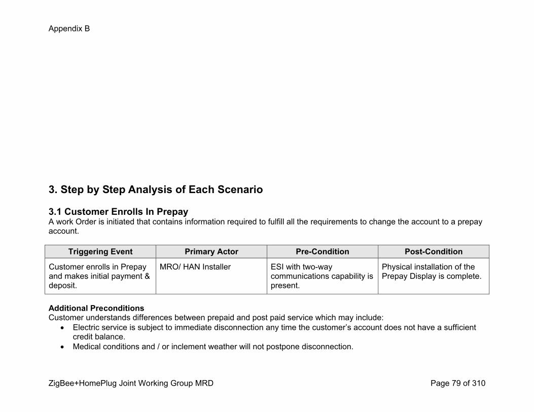
Appendix B
ZigBee+HomePlug Joint Working Group MRD Page 79 of 310
3. Step by Step Analysis of Each Scenario
3.1 Customer Enrolls In PrepayA work Order is initiated that contains information required to fulfill all the requirements to change the account to a prepay account.
Triggering Event Primary Actor PreCondition PostCondition
Customer enrolls in Prepay and makes initial payment & deposit.
MRO/ HAN Installer ESI with twoway communications capability is present.
Physical installation of the Prepay Display is complete.
Additional PreconditionsCustomer understands differences between prepaid and post paid service which may include:
! Electric service is subject to immediate disconnection any time the customer’s account does not have a sufficient credit balance.
! Medical conditions and / or inclement weather will not postpone disconnection.

Appendix B
ZigBee+HomePlug Joint Working Group MRD Page 80 of 310
! Prepaid accounts are not eligible for payment arrangements.! Energy assistance will be credited to their account once payment is received.! Prepaid customers are not subject to normal collection fees.! Payments can be made in any amount. If service is turned off due to a credit deficit the customer may be subject to pay any outstanding balance and pay a minimum required payment that is credited toward future energy use.
! Customer is informed of pay options which may include check, credit, debit, cash, in one or more of the following locations, web, phone, in person, paystation (authorized grocery, convenience stores), and kiosk.
! Customer may not receive a paper statement. Customer account history, usage, charges, and payment will be available via methods supported by the utility (e.g. web or Interactive Voice Response System)
! Service terminated at the request of the customer will result in the refund of any remaining credit on the prepay account.
! A Customer returning account to post paid service from prepay may have a deposit required as a condition of continued service.
3.1.1 Steps for this scenario
Step # Actor Description of the Step Additional Notes
1 Customer Customer receives information about prepay and enrolls into the utilities’ Prepay Program via Call Center or web application.
Utility business rules may exclude Medical / Life support customers from participating in Prepay.
2 Call Center Agent / web
Call Center Agent / web initiates a prepay association within CIS with the targeted meter.
3 Customer Customer pays minimum initial payment for purchase of kWh. The Customer may pay a deposit for a HAN device and / or a deposit based on the customer’s arrears.
Initial minimum customer payments for purchase of kWh are

Appendix B
ZigBee+HomePlug Joint Working Group MRD Page 81 of 310
Step # Actor Description of the Step Additional Notes
typically $10 to $25. Alternatively, an amount could be estimated based on historical consumption.
4 CIS CIS receives initial Prepay payment notification and converts customer’s payment into a Remaining kWh value.
The Prepay Customer may or may not have outstanding arrears. The initial payment likely won’t follow the utilities’ Payment Priority Rules that are applicable for subsequent payments (e.g. 30% toward any outstanding balance, etc).
5 CIS CIS generates a Prepay Work Order to fulfill requirements of becoming a prepay customer.
! The order includes both customer and premise specific information for identity. (see install use cases)
! The order includes the initial Remaining kWh value that will be used to program into the AMI Meter’s Remaining kWh Register.
! The order will create within the AMI system an association between the customer’s AMI meter identifying the meter as a Prepay meter.
Consideration: The utility can wait until the payment is verified or switch the customer to prepay prior to the initial payment being verified.
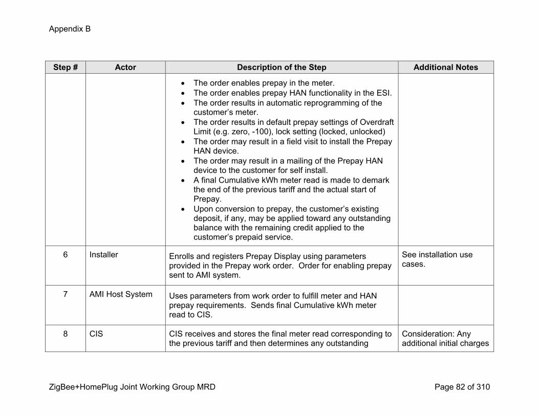
Appendix B
ZigBee+HomePlug Joint Working Group MRD Page 82 of 310
Step # Actor Description of the Step Additional Notes
! The order enables prepay in the meter.! The order enables prepay HAN functionality in the ESI.! The order results in automatic reprogramming of the customer’s meter.
! The order results in default prepay settings of Overdraft Limit (e.g. zero, 100), lock setting (locked, unlocked)
! The order may result in a field visit to install the Prepay HAN device.
! The order may result in a mailing of the Prepay HAN device to the customer for self install.
! A final Cumulative kWh meter read is made to demark the end of the previous tariff and the actual start of Prepay.
! Upon conversion to prepay, the customer’s existing deposit, if any, may be applied toward any outstanding balance with the remaining credit applied to the customer’s prepaid service.
6 Installer Enrolls and registers Prepay Display using parameters provided in the Prepay work order. Order for enabling prepay sent to AMI system.
See installation use cases.
7 AMI Host System Uses parameters from work order to fulfill meter and HAN prepay requirements. Sends final Cumulative kWh meter read to CIS.
8 CIS CIS receives and stores the final meter read corresponding to the previous tariff and then determines any outstanding
Consideration: Any additional initial charges

Appendix B
ZigBee+HomePlug Joint Working Group MRD Page 83 of 310
Step # Actor Description of the Step Additional Notes
payment due since the customer was last billed. This amount is placed into the Arrears category on the customers account.
are not subtracted from the initial purchased kWh value.
3.2 Prepay Customer Makes Payment Use CasesUse case scenarios 3.2 to 3.6 describe CIS processes and interactions of various systems for payment and or failure to pay scenarios. These financial processes also apply to subsequent payments, credits and debits. These scenarios also depict required interfaces and sequence of transactions between systems.
Triggering Event Primary Actor PreCondition PostCondition
Customer makes payment. CIS Customer is enrolled in Prepay.
The prepay program state is set to post payment status.
3.2.1 Steps for this scenario
Step # Actor Description of the Step Additional Notes
1 Customer Customer makes payment using an existing payment method.
2 CIS CIS receives instant prenotification file. A prenotification payment is an unverified payment.
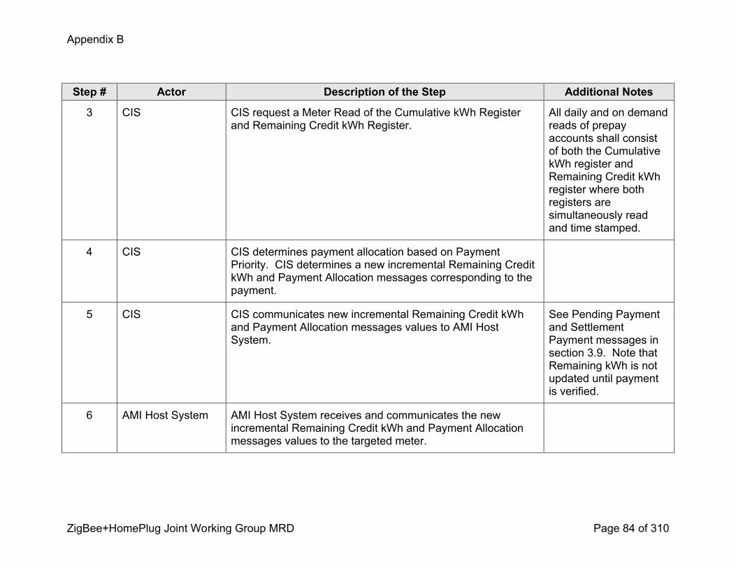
Appendix B
ZigBee+HomePlug Joint Working Group MRD Page 84 of 310
Step # Actor Description of the Step Additional Notes
3 CIS CIS request a Meter Read of the Cumulative kWh Register and Remaining Credit kWh Register.
All daily and on demand reads of prepay accounts shall consist of both the Cumulative kWh register and Remaining Credit kWh register where both registers are simultaneously read and time stamped.
4 CIS CIS determines payment allocation based on Payment Priority. CIS determines a new incremental Remaining Credit kWh and Payment Allocation messages corresponding to the payment.
5 CIS CIS communicates new incremental Remaining Credit kWh and Payment Allocation messages values to AMI Host System.
See Pending Payment and Settlement Payment messages in section 3.9. Note that Remaining kWh is not updated until payment is verified.
6 AMI Host System AMI Host System receives and communicates the new incremental Remaining Credit kWh and Payment Allocation messages values to the targeted meter.

Appendix B
ZigBee+HomePlug Joint Working Group MRD Page 85 of 310
Step # Actor Description of the Step Additional Notes
7 Meter Meter receives the new incremental Remaining Credit kWh updates the Remaining Credit kWh register.
8 Meter If Remaining Credit kWh is a positive number and the Remote Service Switch (RSS) is open, the meter will close the RSS switch automatically.
A business rule might require a minimum threshold above zero (e.g. 1 kWh)
9 Meter Meter communicates Payment Allocation messages and Remaining Credit kWh to the Prepay Display.
10 Prepay Display Display acknowledges receipt of messages and updates payment and energy information.
3.3 Customer either fails to make a payment or fails to pay enough.
The customer’s payment or lack of payment puts customer in the red (negative Remaining kWh balance). This scenario allows for automatic disconnection once the customer becomes eligible for disconnect.
Triggering Event Primary Actor PreCondition PostCondition
Meter’s Remaining Credit kWh register read is less than or equal to zero.
CIS Customer is enrolled in Prepay. Notification method(s) are operational. Optional Prepay Display is installed, initialized, and operational.
Customer is disconnected.
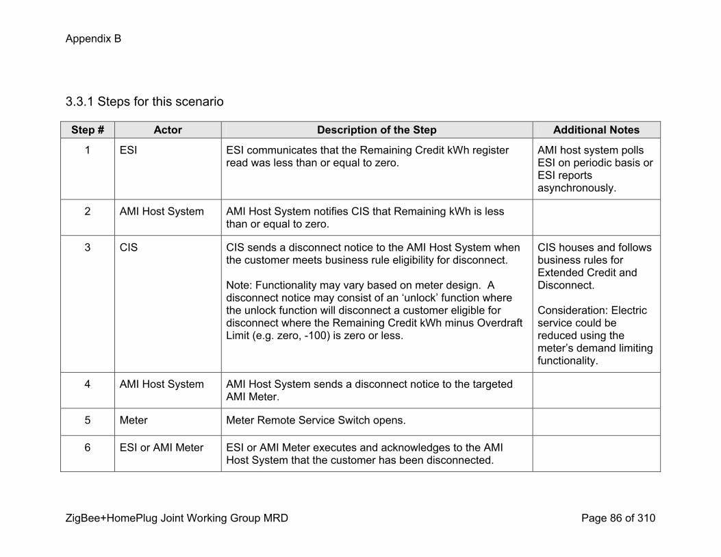
Appendix B
ZigBee+HomePlug Joint Working Group MRD Page 86 of 310
3.3.1 Steps for this scenario
Step # Actor Description of the Step Additional Notes
1 ESI ESI communicates that the Remaining Credit kWh register read was less than or equal to zero.
AMI host system polls ESI on periodic basis or ESI reports asynchronously.
2 AMI Host System AMI Host System notifies CIS that Remaining kWh is less than or equal to zero.
3 CIS CIS sends a disconnect notice to the AMI Host System when the customer meets business rule eligibility for disconnect.
Note: Functionality may vary based on meter design. A disconnect notice may consist of an ‘unlock’ function where the unlock function will disconnect a customer eligible for disconnect where the Remaining Credit kWh minus Overdraft Limit (e.g. zero, 100) is zero or less.
CIS houses and follows business rules for Extended Credit and Disconnect.
Consideration: Electric service could be reduced using the meter’s demand limiting functionality.
4 AMI Host System AMI Host System sends a disconnect notice to the targeted AMI Meter.
5 Meter Meter Remote Service Switch opens.
6 ESI or AMI Meter ESI or AMI Meter executes and acknowledges to the AMI Host System that the customer has been disconnected.

Appendix B
ZigBee+HomePlug Joint Working Group MRD Page 87 of 310
Step # Actor Description of the Step Additional Notes
7 AMI Host System AMI Host System receives confirmation and communicates to CIS that customer is disconnected.
8 CIS CIS records successful disconnect.
3.4 Customer payment is reversed due to dishonored negotiable instrument and Remaining Credit is less than or equal to zero.
The customer’s returned item (e.g. check, money order, cashier check) results in the customer being disconnected. The Business Rules used for this use case are repeated below. 1. Should a dishonored negotiable instrument (DNI) result in the Customer’s prepaid service balance reaching
zero, the Customer shall have one (1) business day to make an adequate payment to avoid disconnection. 2. DNI fees are added to miscellaneous charges. Future payments are processed according to previously listed
payment priority.
Triggering Event Primary Actor PreCondition PostCondition
CIS receives notification of dishonored negotiable instrument (DNI).
CIS Customer is enrolled in Prepay. Notification method(s) are operational. Optional Prepay Display is installed, initialized, and operational.
The prepay program state is set to post DNI status.
3.4.1 Steps for this scenario
Step # Actor Description of the Step Additional Notes
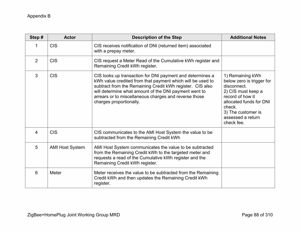
Appendix B
ZigBee+HomePlug Joint Working Group MRD Page 88 of 310
Step # Actor Description of the Step Additional Notes
1 CIS CIS receives notification of DNI (returned item) associated with a prepay meter.
2 CIS CIS request a Meter Read of the Cumulative kWh register and Remaining Credit kWh register.
3 CIS CIS looks up transaction for DNI payment and determines a kWh value credited from that payment which will be used to subtract from the Remaining Credit kWh register. CIS also will determine what amount of the DNI payment went to arrears or to miscellaneous charges and reverse those charges proportionally.
1) Remaining kWh below zero is trigger for disconnect.2) CIS must keep a record of how it allocated funds for DNI check.3) The customer is assessed a return check fee.
4 CIS CIS communicates to the AMI Host System the value to be subtracted from the Remaining Credit kWh
5 AMI Host System AMI Host System communicates the value to be subtracted from the Remaining Credit kWh to the targeted meter and requests a read of the Cumulative kWh register and the Remaining Credit kWh register.
6 Meter Meter receives the value to be subtracted from the Remaining Credit kWh and then updates the Remaining Credit kWh register.
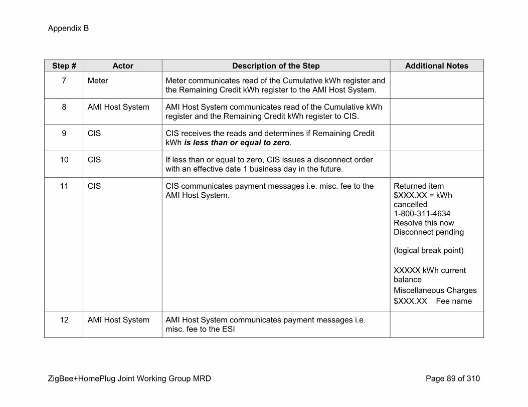
Appendix B
ZigBee+HomePlug Joint Working Group MRD Page 89 of 310
Step # Actor Description of the Step Additional Notes
7 Meter Meter communicates read of the Cumulative kWh register and the Remaining Credit kWh register to the AMI Host System.
8 AMI Host System AMI Host System communicates read of the Cumulative kWh register and the Remaining Credit kWh register to CIS.
9 CIS CIS receives the reads and determines if Remaining Credit kWh is less than or equal to zero.
10 CIS If less than or equal to zero, CIS issues a disconnect order with an effective date 1 business day in the future.
11 CIS CIS communicates payment messages i.e. misc. fee to the AMI Host System.
Returned item$XXX.XX = kWh cancelled18003114634Resolve this nowDisconnect pending
(logical break point)
XXXXX kWh current balance Miscellaneous Charges$XXX.XX Fee name
12 AMI Host System AMI Host System communicates payment messages i.e. misc. fee to the ESI

Appendix B
ZigBee+HomePlug Joint Working Group MRD Page 90 of 310
Step # Actor Description of the Step Additional Notes
13 ESI ESI acknowledges AMI Host System and communicates payment messages i.e. misc. fee to the Prepay Display
14 Prepay Display Prepay Display acknowledges receipt of messages.
15 Prepay Display Prepay Display updates payment messages and energy information.
3.5 Customer payment is reversed due to dishonored negotiable instrument. Remaining Credit is greater than zero.The customer’s returned item results payment reversal, however in this case the customer remains connected as their balance is greater than zero.
Triggering Event Primary Actor PreCondition PostCondition
CIS receives notification of dishonored negotiable instrument (DNI).
CIS Customer is enrolled in Prepay. Notification method(s) are operational. Optional Prepay Display is installed, initialized, and operational.
The prepay program state is set to post DNI status.
3.5.1 Steps for this scenario
Step # Actor Description of the Step Additional Notes
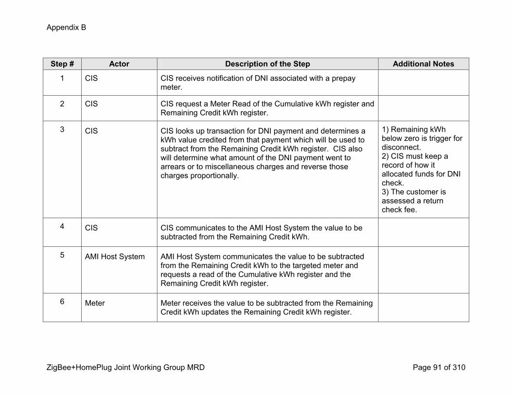
Appendix B
ZigBee+HomePlug Joint Working Group MRD Page 91 of 310
Step # Actor Description of the Step Additional Notes
1 CIS CIS receives notification of DNI associated with a prepay meter.
2 CIS CIS request a Meter Read of the Cumulative kWh register and Remaining Credit kWh register.
3 CIS CIS looks up transaction for DNI payment and determines a kWh value credited from that payment which will be used to subtract from the Remaining Credit kWh register. CIS also will determine what amount of the DNI payment went to arrears or to miscellaneous charges and reverse those charges proportionally.
1) Remaining kWh below zero is trigger for disconnect.2) CIS must keep a record of how it allocated funds for DNI check.3) The customer is assessed a return check fee.
4 CIS CIS communicates to the AMI Host System the value to be subtracted from the Remaining Credit kWh.
5 AMI Host System AMI Host System communicates the value to be subtracted from the Remaining Credit kWh to the targeted meter and requests a read of the Cumulative kWh register and the Remaining Credit kWh register.
6 Meter Meter receives the value to be subtracted from the Remaining Credit kWh updates the Remaining Credit kWh register.
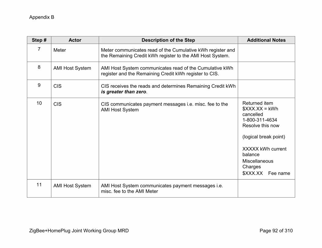
Appendix B
ZigBee+HomePlug Joint Working Group MRD Page 92 of 310
Step # Actor Description of the Step Additional Notes
7 Meter Meter communicates read of the Cumulative kWh register and the Remaining Credit kWh register to the AMI Host System.
8 AMI Host System AMI Host System communicates read of the Cumulative kWh register and the Remaining Credit kWh register to CIS.
9 CIS CIS receives the reads and determines Remaining Credit kWh is greater than zero.
10 CIS CIS communicates payment messages i.e. misc. fee to the AMI Host System
Returned item$XXX.XX = kWh cancelled18003114634Resolve this now
(logical break point)
XXXXX kWh current balance Miscellaneous Charges$XXX.XX Fee name
11 AMI Host System AMI Host System communicates payment messages i.e. misc. fee to the AMI Meter

Appendix B
ZigBee+HomePlug Joint Working Group MRD Page 93 of 310
Step # Actor Description of the Step Additional Notes
12 Meter AMI Meter acknowledges AMI Host System and communicates payment messages i.e. misc. fee to the Prepay Display
13 Prepay Display Prepay Display acknowledges receipt of messages.
14 Prepay Display Prepay Display updates payment messages and energy information.
3.6 Customer makes required payment to be reconnectedThe customer’s payment puts customer in the black (positive Remaining kWh balance). This scenario allows for automatic reconnection once the customer becomes eligible for reconnect.
Triggering Event Primary Actor PreCondition PostCondition
Customer makes required payment to be reconnected
CIS Customer is enrolled in Prepay. Customer is disconnected.
The customer’s power is reconnected.
3.6.1 Steps for this scenario
Step # Actor Description of the Step Additional Notes
1 Customer Customer makes required payment to have service restored
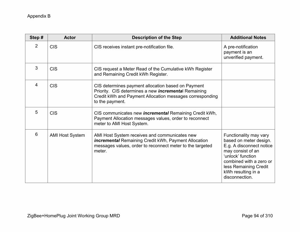
Appendix B
ZigBee+HomePlug Joint Working Group MRD Page 94 of 310
Step # Actor Description of the Step Additional Notes
2 CIS CIS receives instant prenotification file. A prenotification payment is an unverified payment.
3 CIS CIS request a Meter Read of the Cumulative kWh Register and Remaining Credit kWh Register.
4 CIS CIS determines payment allocation based on Payment Priority. CIS determines a new incremental Remaining Credit kWh and Payment Allocation messages corresponding to the payment.
5 CIS CIS communicates new incremental Remaining Credit kWh, Payment Allocation messages values, order to reconnect meter to AMI Host System.
6 AMI Host System AMI Host System receives and communicates new incremental Remaining Credit kWh, Payment Allocation messages values, order to reconnect meter to the targeted meter.
Functionality may vary based on meter design. E.g. A disconnect notice may consist of an ‘unlock’ function combined with a zero or less Remaining Credit kWh resulting in a disconnection.

Appendix B
ZigBee+HomePlug Joint Working Group MRD Page 95 of 310
Step # Actor Description of the Step Additional Notes
7 Meter Meter receives and acknowledges new incremental Remaining Credit kWh, Payment Allocation messages values, and an order to reconnect. Meter reconnects automatically.
Need to determine meter’s capabilities and firm up procedures.
8 Meter Meter communicates Payment Allocation messages and Remaining Credit kWh to the Prepay Display.
9 Prepay Display Display acknowledges receipt of messages and updates payment and energy information.
3.7 Remaining Credit kWh Adjustment Algorithm Use CaseAn adjustment algorithm for the Remaining Credit kWh may be required for the following scenarios.
! The utility elects in its implementation of prepay for the CIS system to be the system of record for determining and maintaining the balance for Remaining Credit kWh.
! An automated process sets a new value for Remaining Credit kWh to overwrite the existing Remaining Credit kWh.The adjustment algorithm allows for an adjustment at the meter for energy consumption used by the customer. The time period of the adjustment is the time between the obtainment of the Cumulative kWh register used to calculate Remaining Credit kWh and the Cumulative kWh register at the time the Remaining Credit kWh is populated in the meter.
Triggering Event Primary Actor PreCondition PostCondition
CIS is triggered to set Remaining Credit kWh.
ESI Customer is enrolled in Prepay.
Remaining Credit kWh is set in the Remaining Credit kWh register.
3.7.1 Steps for this scenario
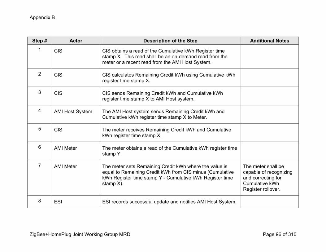
Appendix B
ZigBee+HomePlug Joint Working Group MRD Page 96 of 310
Step # Actor Description of the Step Additional Notes
1 CIS CIS obtains a read of the Cumulative kWh Register time stamp X. This read shall be an ondemand read from the meter or a recent read from the AMI Host System.
2 CIS CIS calculates Remaining Credit kWh using Cumulative kWh register time stamp X.
3 CIS CIS sends Remaining Credit kWh and Cumulative kWh register time stamp X to AMI Host system.
4 AMI Host System The AMI Host system sends Remaining Credit kWh and Cumulative kWh register time stamp X to Meter.
5 CIS The meter receives Remaining Credit kWh and Cumulative kWh register time stamp X.
6 AMI Meter The meter obtains a read of the Cumulative kWh register time stamp Y.
7 AMI Meter The meter sets Remaining Credit kWh where the value is equal to Remaining Credit kWh from CIS minus (Cumulative kWh Register time stamp Y Cumulative kWh Register time stamp X).
The meter shall be capable of recognizing and correcting for Cumulative kWh Register rollover.
8 ESI ESI records successful update and notifies AMI Host System.
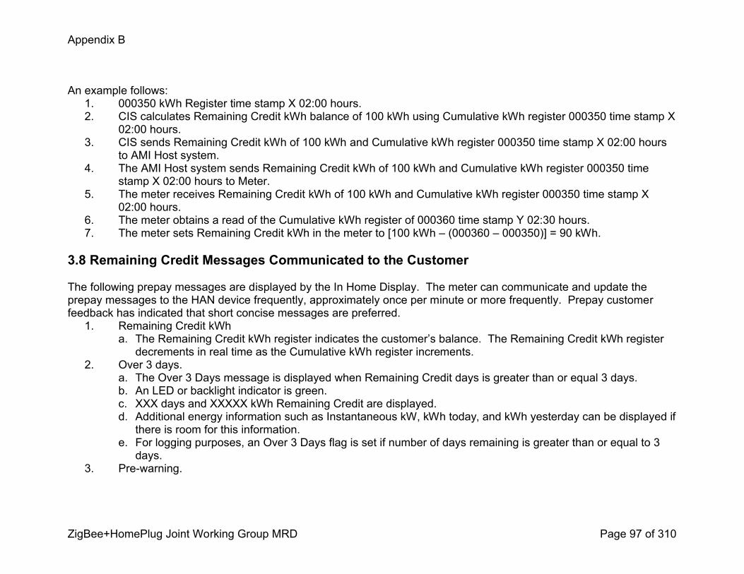
Appendix B
ZigBee+HomePlug Joint Working Group MRD Page 97 of 310
An example follows:1. 000350 kWh Register time stamp X 02:00 hours. 2. CIS calculates Remaining Credit kWh balance of 100 kWh using Cumulative kWh register 000350 time stamp X
02:00 hours.3. CIS sends Remaining Credit kWh of 100 kWh and Cumulative kWh register 000350 time stamp X 02:00 hours
to AMI Host system.4. The AMI Host system sends Remaining Credit kWh of 100 kWh and Cumulative kWh register 000350 time
stamp X 02:00 hours to Meter.5. The meter receives Remaining Credit kWh of 100 kWh and Cumulative kWh register 000350 time stamp X
02:00 hours. 6. The meter obtains a read of the Cumulative kWh register of 000360 time stamp Y 02:30 hours.7. The meter sets Remaining Credit kWh in the meter to [100 kWh – (000360 – 000350)] = 90 kWh.
3.8 Remaining Credit Messages Communicated to the Customer
The following prepay messages are displayed by the In Home Display. The meter can communicate and update the prepay messages to the HAN device frequently, approximately once per minute or more frequently. Prepay customer feedback has indicated that short concise messages are preferred.1. Remaining Credit kWh
a. The Remaining Credit kWh register indicates the customer’s balance. The Remaining Credit kWh register decrements in real time as the Cumulative kWh register increments.
2. Over 3 days. a. The Over 3 Days message is displayed when Remaining Credit days is greater than or equal 3 days. b. An LED or backlight indicator is green.c. XXX days and XXXXX kWh Remaining Credit are displayed. d. Additional energy information such as Instantaneous kW, kWh today, and kWh yesterday can be displayed if there is room for this information.
e. For logging purposes, an Over 3 Days flag is set if number of days remaining is greater than or equal to 3 days.
3. Prewarning.
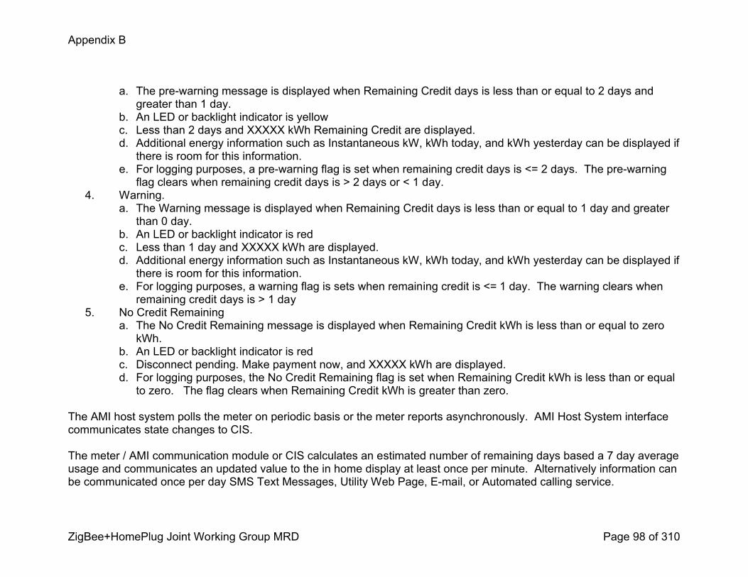
Appendix B
ZigBee+HomePlug Joint Working Group MRD Page 98 of 310
a. The prewarning message is displayed when Remaining Credit days is less than or equal to 2 days and greater than 1 day.
b. An LED or backlight indicator is yellow c. Less than 2 days and XXXXX kWh Remaining Credit are displayed.d. Additional energy information such as Instantaneous kW, kWh today, and kWh yesterday can be displayed if there is room for this information.
e. For logging purposes, a prewarning flag is set when remaining credit days is <= 2 days. The prewarning flag clears when remaining credit days is > 2 days or < 1 day.
4. Warning.a. The Warning message is displayed when Remaining Credit days is less than or equal to 1 day and greater than 0 day.
b. An LED or backlight indicator is red c. Less than 1 day and XXXXX kWh are displayed.d. Additional energy information such as Instantaneous kW, kWh today, and kWh yesterday can be displayed if there is room for this information.
e. For logging purposes, a warning flag is sets when remaining credit is <= 1 day. The warning clears when remaining credit days is > 1 day
5. No Credit Remaininga. The No Credit Remaining message is displayed when Remaining Credit kWh is less than or equal to zero kWh.
b. An LED or backlight indicator is red c. Disconnect pending. Make payment now, and XXXXX kWh are displayed.d. For logging purposes, the No Credit Remaining flag is set when Remaining Credit kWh is less than or equal to zero. The flag clears when Remaining Credit kWh is greater than zero.
The AMI host system polls the meter on periodic basis or the meter reports asynchronously. AMI Host System interface communicates state changes to CIS.
The meter / AMI communication module or CIS calculates an estimated number of remaining days based a 7 day average usage and communicates an updated value to the in home display at least once per minute. Alternatively information can be communicated once per day SMS Text Messages, Utility Web Page, Email, or Automated calling service.

Appendix B
ZigBee+HomePlug Joint Working Group MRD Page 99 of 310
An algorithm is required to estimate Remaining Credit Days, an example follows. Remaining Credit Days = (Remaining Credit kWh) / average of the midnight to midnight kWh values totaled for each of the previous seven days. Assume a daily average of 33 kWh for any of the seven days that does not have usage history. Limit the maximum number of Remaining Credit Days displayed to 365 days. Alternatively, CIS could send an estimated daily average for that customer based on previous history or other demographics.
3.9 Freeform Messages Communicated to the Customer
Energy Information messages are available for display using a Prepay Display scroll button or navigation menu.
1. Call Center Phonea. Utility nameb. 18001234567c. Message can reside in a program in the meter. Message does not expire unless directed by the AMI Host System to expire.
2. DNI 1a. Returned itemb. $XXX.XX = kWh cancelledc. 18001234567d. Resolve this nowe. Disconnect pendingf. XXXXX kWh current balanceg. CIS invokes an on demand request to display the DNI message. Message becomes default messagedisplayed. CIS invokes an on demand request to clear the message. Remaining Credit kWh is less than or equal to zero.
3. DNI 2a. Returned itemb. $XXX.XX = kWh cancelledc. 18001234567

Appendix B
ZigBee+HomePlug Joint Working Group MRD Page 100 of 310
d. Resolve this nowe. XXXXX kWh current balancef. CIS invokes an on demand request to display the DNI message. Message becomes default message displayed. CIS invokes an on demand request to clear the message.
4. Remaining Credit kWh is greater than zero.a. Pending Paymentb. Pending $XX.XX payment and estimated XXXX kWh purchased.c. XXXXX kWh Current balanced. Triggered by customer payment; initial payment is not a verified payment. The customer is informed of their payment and the estimated kWh that will result. This amount is not added to the Remaining Credit kWh register until payment is verified.
5. Settlement Paymenta. $XXX.XX payment received MMDD. Thanks!b. $XXX.XX toward misc. charges c. $XXXX.XX toward arrearsd. $XXX.XX = XXXX kWh prepaide. Triggered by settlement. CIS receives a customer payment amount and determines amount of the paymenttoward the purchase of additional credit. (Payment minus arrears and misc.) CIS invokes an on demand policy to display customer payment amount and corresponding remaining kWh credit purchased. Clear message after expiration, typically 24 hours after initial posting.
6. Misc. chargesa. Miscellaneous Chargesb. $XXX.XX Fee namec. CIS invokes an on demand policy to display the Misc. fee message. Display Fee name and amount. Clear message after expiration, typically 24 hours after initial posting.

Appendix B
ZigBee+HomePlug Joint Working Group MRD Page 101 of 310
3.10 Customer opts out of AMI Prepay ProgramThe customer closes their prepay account.
Triggering Event Primary Actor PreCondition PostCondition
Customer opts out of AMI Prepay Program.
Call Center Agent / Web ESI with twoway communications capability is present.
Prepay Display’s registration is revoked and HAN Device Communications are terminated at the ESI.
3.10.1 Steps for this scenario
Step # Actor Description of the Step Additional Notes
1 Customer Customer chooses to opt out of AMI Prepay Program.
2 Call Center Agent / Web
Call Center Agent / Web informs CIS that customer no longer wants to participate.
3 CIS CIS generates a Meter Work Order that causes a Meter Technician to reprogram the AMI Meter to the appropriate tariff (e.g. Remove Prepay). CIS denotes effective date of program termination and makes accounting adjustments as deemed necessary per the tariff guidelines.
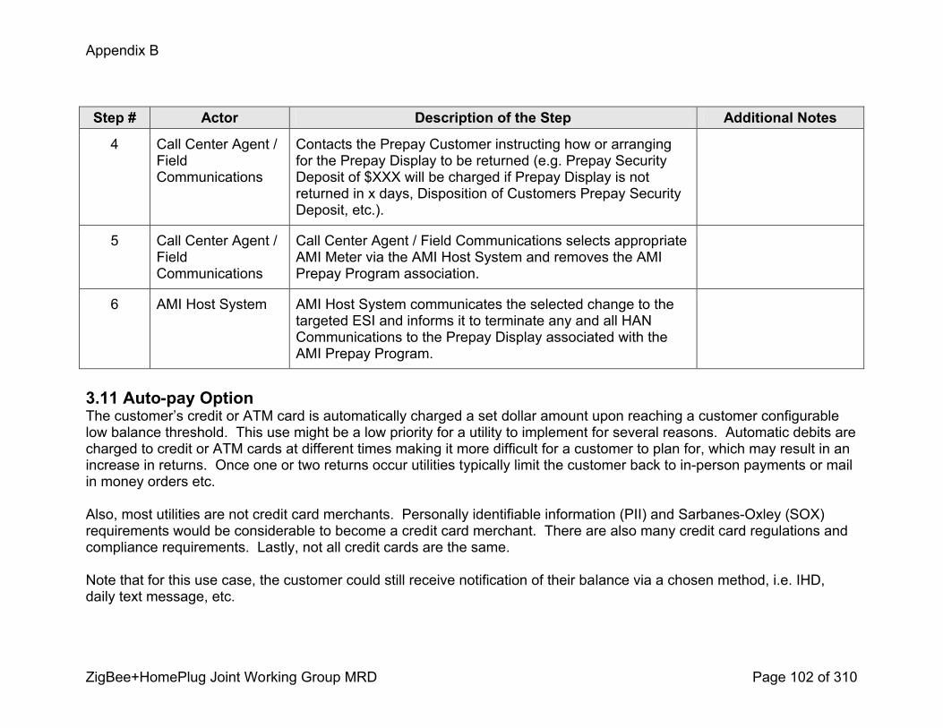
Appendix B
ZigBee+HomePlug Joint Working Group MRD Page 102 of 310
Step # Actor Description of the Step Additional Notes
4 Call Center Agent / Field Communications
Contacts the Prepay Customer instructing how or arranging for the Prepay Display to be returned (e.g. Prepay Security Deposit of $XXX will be charged if Prepay Display is not returned in x days, Disposition of Customers Prepay Security Deposit, etc.).
5 Call Center Agent / Field Communications
Call Center Agent / Field Communications selects appropriate AMI Meter via the AMI Host System and removes the AMI Prepay Program association.
6 AMI Host System AMI Host System communicates the selected change to the targeted ESI and informs it to terminate any and all HAN Communications to the Prepay Display associated with the AMI Prepay Program.
3.11 Autopay OptionThe customer’s credit or ATM card is automatically charged a set dollar amount upon reaching a customer configurable low balance threshold. This use might be a low priority for a utility to implement for several reasons. Automatic debits are charged to credit or ATM cards at different times making it more difficult for a customer to plan for, which may result in an increase in returns. Once one or two returns occur utilities typically limit the customer back to inperson payments or mail in money orders etc.
Also, most utilities are not credit card merchants. Personally identifiable information (PII) and SarbanesOxley (SOX) requirements would be considerable to become a credit card merchant. There are also many credit card regulations and compliance requirements. Lastly, not all credit cards are the same.
Note that for this use case, the customer could still receive notification of their balance via a chosen method, i.e. IHD, daily text message, etc.

Appendix B
ZigBee+HomePlug Joint Working Group MRD Page 103 of 310
Triggering Event Primary Actor PreCondition PostCondition
Customer signs up for Autopay option.
Call Center Agent / Web Customer is enrolled in a prepay program.
Customer’s prepay balance is automatically topped off with a customer configured dollar amount upon reaching a customer configured threshold.
3.11.1 Steps for this scenario
Step # Actor Description of the Step Additional Notes
1 Customer Customer contacts utility Call Center Agent / web to sign up for Autopay option
2 Call Center Agent / Web
Call Center Agent / Web provides information regarding how the Autopay option works.
3 Customer The customer selects from utility define dollar amounts (e.g. $10, $15, $20, etc) that are automatically purchased when the kWh balance threshold is reached.
4 Customer The customer selects from utility defined Remaining Credit threshold in dollars or kWh (e.g. $10 or 50 kWh) at which additional dollars are automatically purchased using their Credit or ATM card.

Appendix B
ZigBee+HomePlug Joint Working Group MRD Page 104 of 310
Step # Actor Description of the Step Additional Notes
5 Call Center Agent / Web
Customer chooses thresholds and provides credit / ATM card information. Information is recorded in CIS.
6 CIS CIS checks daily the customer’s prepay account balance to see if the balance is less than or equal to the customer defined threshold.
CIS also checks daily for expired credit or ATM card. Customer is contacted to obtain current information.
7 CIS If the customer’s prepay account balance is less than the defined threshold, CIS automatically purchases additional kWh prepaid for the customer.
Option: A prompt to the customer asking if the customer would like to top off their meter with a kWh purchase.
8 CIS CIS communicates prepaid purchase and balance information to the customer.
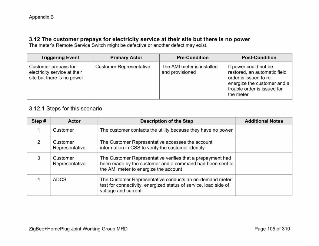
Appendix B
ZigBee+HomePlug Joint Working Group MRD Page 105 of 310
3.12 The customer prepays for electricity service at their site but there is no powerThe meter’s Remote Service Switch might be defective or another defect may exist.
Triggering Event Primary Actor PreCondition PostCondition
Customer prepays for electricity service at their site but there is no power
Customer Representative The AMI meter is installed and provisioned
If power could not be restored, an automatic field order is issued to reenergize the customer and a trouble order is issued for the meter
3.12.1 Steps for this scenario
Step # Actor Description of the Step Additional Notes
1 Customer The customer contacts the utility because they have no power
2 Customer Representative
The Customer Representative accesses the account information in CSS to verify the customer identity
3 Customer Representative
The Customer Representative verifies that a prepayment had been made by the customer and a command had been sent to the AMI meter to energize the account
4 ADCS The Customer Representative conducts an ondemand meter test for connectivity, energized status of service, load side of voltage and current

Appendix B
ZigBee+HomePlug Joint Working Group MRD Page 106 of 310
Step # Actor Description of the Step Additional Notes
5 AMI Meter The meter receives, logs and processes the request and sends the results to the ADCS
6 ADCS The ADCS receives and logs the request, then sends the results to the MDMS
7 MDMS The MDMS receives and logs the test results and makes the information available to other systems (e.g. CSS, trouble order system)
8 Customer Representative
The Customer Representative views the test results in CSS
9 Customer Representative
If the meter passed the test, the Customer Representative will send a command using the CSS to the ADCS to activate the prepayment account
10 Customer Representative
If there is still no power at customer site, or the meter failed the meter test, an automatic field order will be generated to activate service and trouble order for the meter will be issued.
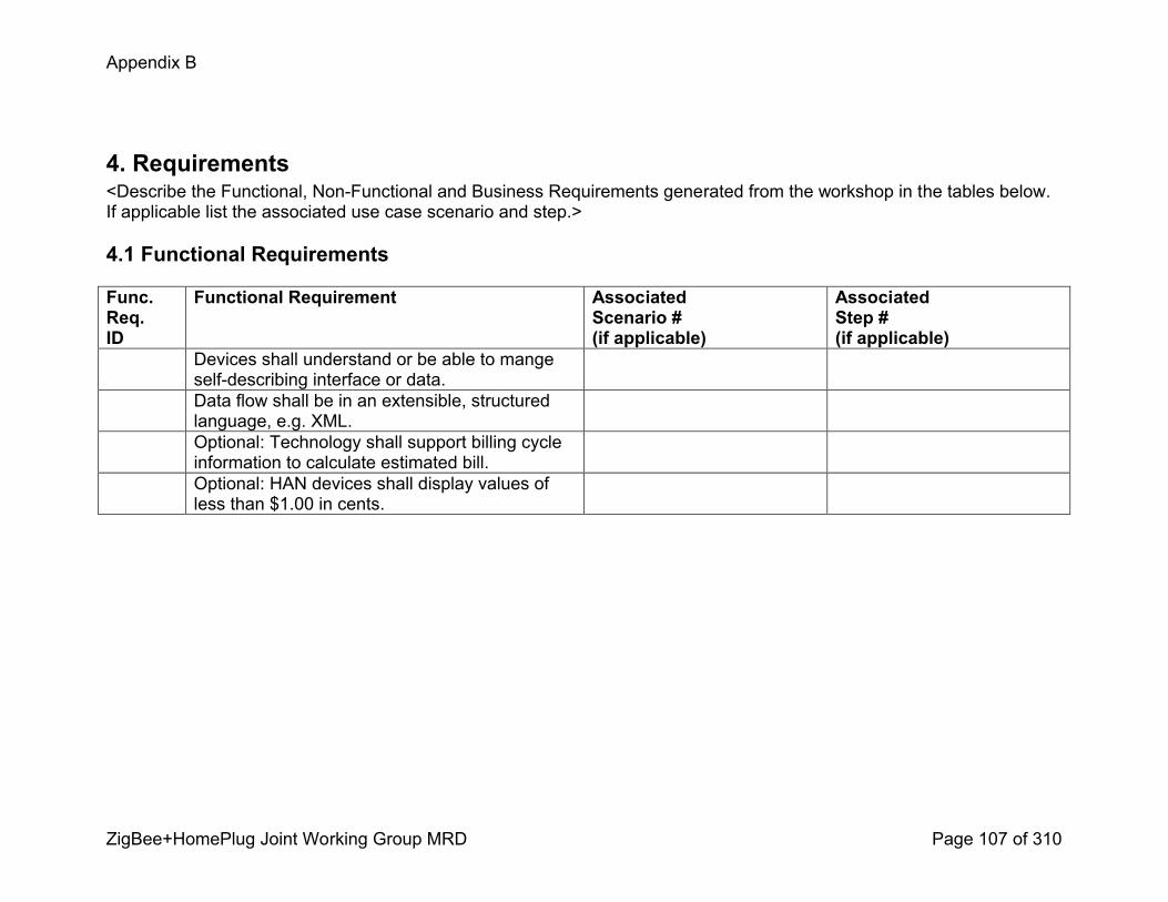
Appendix B
ZigBee+HomePlug Joint Working Group MRD Page 107 of 310
4. Requirements<Describe the Functional, NonFunctional and Business Requirements generated from the workshop in the tables below. If applicable list the associated use case scenario and step.>
4.1 Functional Requirements
Func.Req.ID
Functional Requirement AssociatedScenario #(if applicable)
AssociatedStep #(if applicable)
Devices shall understand or be able to mange selfdescribing interface or data.Data flow shall be in an extensible, structured language, e.g. XML.Optional: Technology shall support billing cycle information to calculate estimated bill.Optional: HAN devices shall display values of less than $1.00 in cents.

Appendix B
ZigBee+HomePlug Joint Working Group MRD Page 108 of 310
User Information and Messages Use Cases
User Information and User Messages
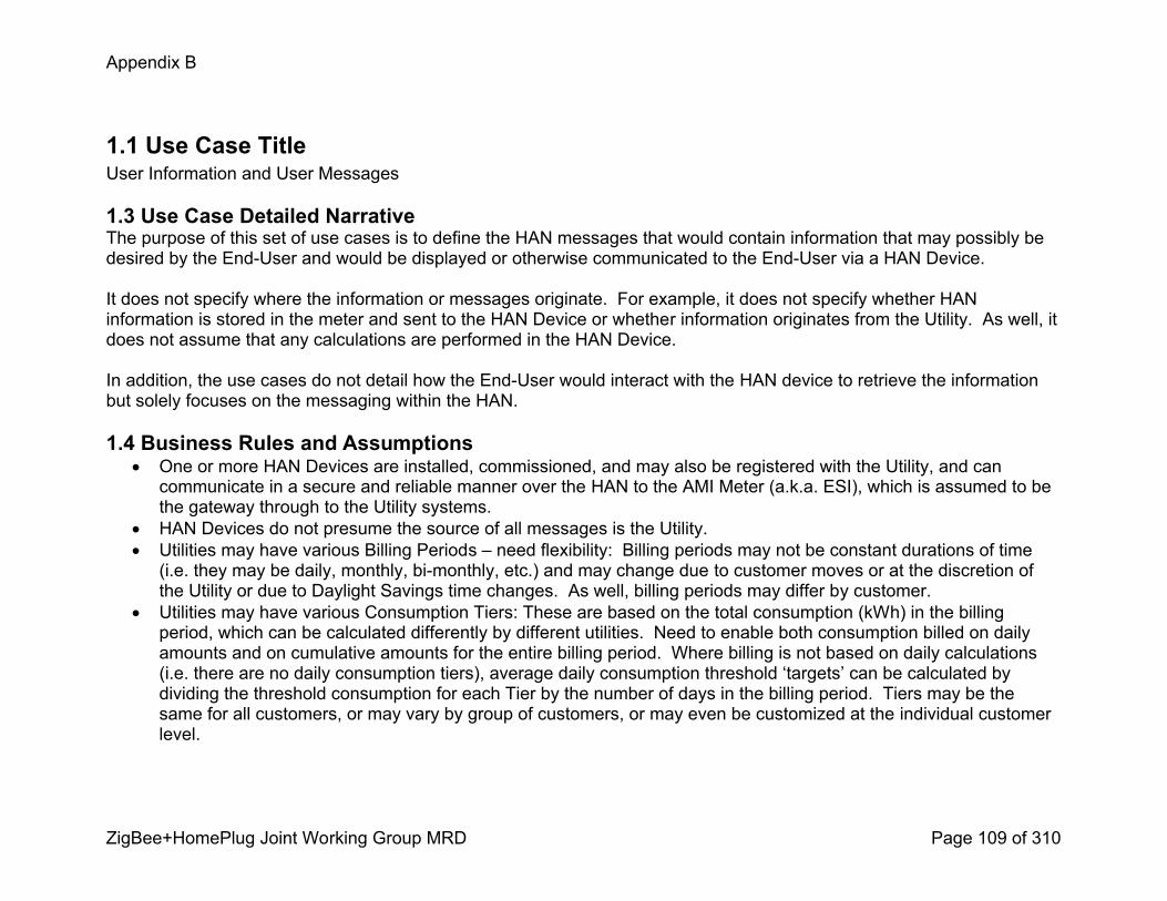
Appendix B
ZigBee+HomePlug Joint Working Group MRD Page 109 of 310
1.1 Use Case TitleUser Information and User Messages
1.3 Use Case Detailed NarrativeThe purpose of this set of use cases is to define the HAN messages that would contain information that may possibly be desired by the EndUser and would be displayed or otherwise communicated to the EndUser via a HAN Device.
It does not specify where the information or messages originate. For example, it does not specify whether HAN information is stored in the meter and sent to the HAN Device or whether information originates from the Utility. As well, it does not assume that any calculations are performed in the HAN Device.
In addition, the use cases do not detail how the EndUser would interact with the HAN device to retrieve the information but solely focuses on the messaging within the HAN.
1.4 Business Rules and Assumptions! One or more HAN Devices are installed, commissioned, and may also be registered with the Utility, and can communicate in a secure and reliable manner over the HAN to the AMI Meter (a.k.a. ESI), which is assumed to be the gateway through to the Utility systems.
! HAN Devices do not presume the source of all messages is the Utility. ! Utilities may have various Billing Periods – need flexibility: Billing periods may not be constant durations of time (i.e. they may be daily, monthly, bimonthly, etc.) and may change due to customer moves or at the discretion of the Utility or due to Daylight Savings time changes. As well, billing periods may differ by customer.
! Utilities may have various Consumption Tiers: These are based on the total consumption (kWh) in the billing period, which can be calculated differently by different utilities. Need to enable both consumption billed on daily amounts and on cumulative amounts for the entire billing period. Where billing is not based on daily calculations (i.e. there are no daily consumption tiers), average daily consumption threshold ‘targets’ can be calculated by dividing the threshold consumption for each Tier by the number of days in the billing period. Tiers may be the same for all customers, or may vary by group of customers, or may even be customized at the individual customer level.
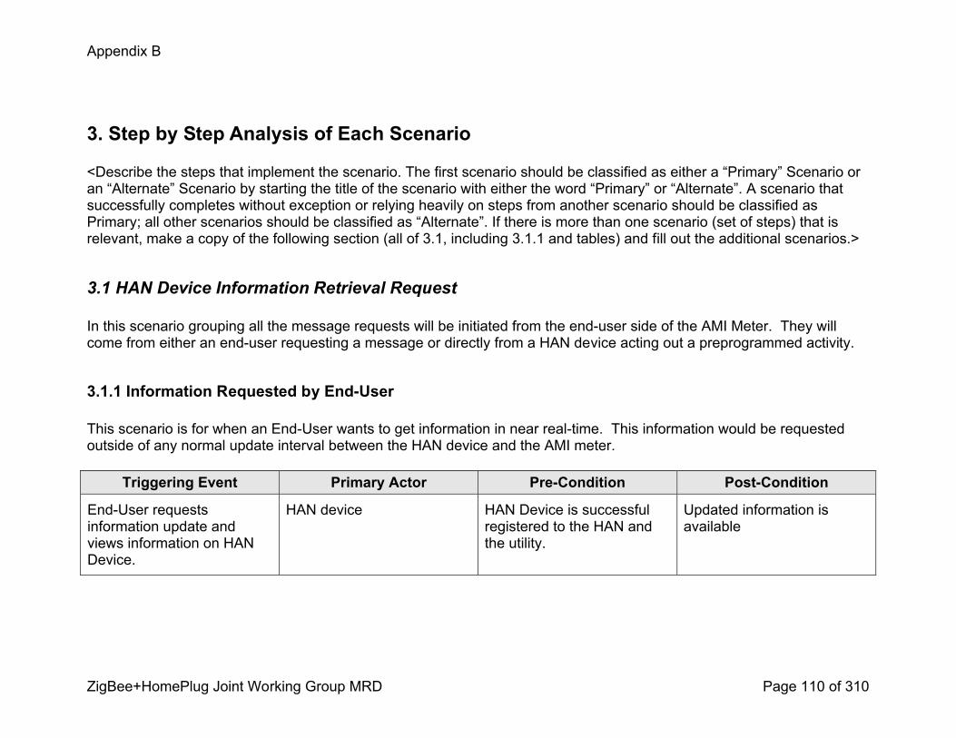
Appendix B
ZigBee+HomePlug Joint Working Group MRD Page 110 of 310
3. Step by Step Analysis of Each Scenario
<Describe the steps that implement the scenario. The first scenario should be classified as either a “Primary” Scenario or an “Alternate” Scenario by starting the title of the scenario with either the word “Primary” or “Alternate”. A scenario that successfully completes without exception or relying heavily on steps from another scenario should be classified as Primary; all other scenarios should be classified as “Alternate”. If there is more than one scenario (set of steps) that is relevant, make a copy of the following section (all of 3.1, including 3.1.1 and tables) and fill out the additional scenarios.>
3.1 HAN Device Information Retrieval Request
In this scenario grouping all the message requests will be initiated from the enduser side of the AMI Meter. They will come from either an enduser requesting a message or directly from a HAN device acting out a preprogrammed activity.
3.1.1 Information Requested by EndUser
This scenario is for when an EndUser wants to get information in near realtime. This information would be requested outside of any normal update interval between the HAN device and the AMI meter.
Triggering Event Primary Actor PreCondition PostCondition
EndUser requests information update and views information on HAN Device.
HAN device HAN Device is successful registered to the HAN and the utility.
Updated information is available

Appendix B
ZigBee+HomePlug Joint Working Group MRD Page 111 of 310
3.1.1.1 Steps for this scenario<Describe the normal sequence of events that is required to complete the scenario.>
Step # Actor Description of the Step Additional Notes
# <What Actor, either primary or secondary is responsible for the activity in this step>
<Describe the actions that take place in this step. The step should be described in active, present tense.>
<Elaborate on any additional description or value of the step to help support the descriptions>
1 EndUser Requests update to information on the HAN Device.These requests could be for:1. Instantaneous Demand (kW) (may require lagtype filter to avoid constantly changing value; perhaps update every 210 seconds)
2. Current Consumption (kWh) for the following time periods: a. Past Hour (moving window of past 60 minutes) b. Day (restarts at midnight – i.e. 12:00:01 AM) c. Week (restarts on Sunday – i.e. 12:00:01 AM)d. Month (month can be defined different ways: (a) calendar monthtodate (b) previous 30 day period measured midnight to midnight, (c) previous 30 day period measured to current time)
e. Billing Period f. Year (since January 1 at midnight – i.e. 12:00:01 AM)
g. For each TOU and CPP period on a daily, weekly, monthly and billing cycle basis
How the HAN Device enables requesting this information is not part of the use case. The use case only outlines the type of data that may need to be displayed to the enduser. This does not factor in whether messages would carry the exact information to be displayed or whether calculations on the information would be required before being displayed.
Unless noted otherwise, frequency of update on display is desired to be

Appendix B
ZigBee+HomePlug Joint Working Group MRD Page 112 of 310
Step # Actor Description of the Step Additional Notes
3. Previous Consumption (kWh) – Day (24 hour period) 4. Cost of current Demand ($/hr) (based on Current Rate)5. Current Rate ($/kWh) (a.k.a. Price) for each possible Inclining Block Tier, TOU period, CPP period, etc., including combinations of the above rates. a. Rates may need to have an expiration date, or period of validity, after which time new rates come into effect. New rates can be scheduled to take effect.
6. Cumulative cost of Energy ($) for the following time periods (cost is only variable energy cost): a. Past Hour b. Day c. Week d. Month e. Billing Period f. Year g. For each TOU and CPP period on a daily, weekly, monthly and billing cycle basis
7. Indication of current TOU period (i.e. status indicator) and the hours covered by that period (e.g. shows if they are in OffPeak, Shoulder, or Peak period and the duration e.g. “Peak 6PM to 8PM”)
8. Current CPP status and the hours covered by that period (e.g. shows if they are in a CPP event and the duration, e.g. “CPP 6PM to 8PM”)
9. Current Consumption Tier (based on cumulative consumption in Billing Period, e.g. Tier 1, Tier 2)
10.Consumption Target, or Budget, (daily kWh or $ target
between 5 and 15 seconds.
Current Rate is the current rate in effect and can be any rate, including Tiered rate, TOU rate and CPP rate.
Cumulative cost of energy is dependent on the various rates (prices) that were in effect during that period of time, of which there may be many.
Carbon Impact calculations unknown –if they require dynamic updates then this could change the use case.
Carbon Footprint: Prefer to use a standard unit of measure if available, which can be converted into “Gallons of gas saved” or some

Appendix B
ZigBee+HomePlug Joint Working Group MRD Page 113 of 310
Step # Actor Description of the Step Additional Notes
based on prorated Tier consumption in billing period) and comparison of consumption to that Target.
11.Benchmark consumption information, such as Peer Comparison and Historical Comparisons.
12.Cumulative Consumption for all Consumption tiers in the Billing Period
13.Peak Demand (kW) and the date & time it occurred for the following time periods: a. within the current bill cycle b. for each TOU time period.
14.Any metrology that is available at the meter (Voltage, instantaneous Power Factor, Amps, VAR, etc.)
15.Forecasted estimated of total billing period consumption and cost, as well as estimate of what tier the End User will be in at the end of the billing cycle, based on an average runrate thus far in the billing period. Also do this on a monthly basis.
16.Current Generation Demand (kW), generation within each TOU bucket, and peak generation in the current bill cycle with the date& time the peak occurred.
17.Temperature at the meter (If this is measured inside the meter it may not be accurate due to heat generated within the meter.)
18.Existing ZigBee Smart Energy Profile information, including ‘version 1.5’ requirements that may not have been identified above.
19.Carbon Impact, for example: a. Quarterly carbon emissions of the customer in tons
other understandable example of environmental impact, e.g. “cars removed from road”, “trees planted”.
Need to support various units of measurement (e.g. metric)
Note: requirements should includeextensible data fields and flexible text message fields

Appendix B
ZigBee+HomePlug Joint Working Group MRD Page 114 of 310
Step # Actor Description of the Step Additional Notes
b. Average emissions for that quarter in tons c. Historic carbon emissions d. Total carbon emissions to datee. Gallons of gas saved to datef. Gallons of gas saved in comparison to average
20.Billing Information, for example: a. Utility name and contact informationb. Rate label (e.g. TOUGS2, 1/3/06), c. start and end dates for the current bill cycle, d. amount due for the current month, e. Estimated bill to date.
21.Text messages, such as requesting a Conservation, or Energy Tip.
2 HAN Device Sends a request to the AMI meter to retrieve the information required to display or calculate what the EndUser requests
3 AMI Meter If the AMI Meter has the requested information it sends the information to the HAN Device.
If the AMI Meter does not have the requested information, it would relay the request to the Utility.
4 Utility If required, the message is received and processed to retrieve the information requested
5 Utility If required, Utility sends message back to the requesting AMI Meter

Appendix B
ZigBee+HomePlug Joint Working Group MRD Page 115 of 310
Step # Actor Description of the Step Additional Notes
6 AMI Meter AMI Meter receives the message and sends it to the requesting HAN Device
7 HAN Device HAN Device receives the message, verifies receipt, processes information and presents information to EndUser
8 EndUser EndUser receives requested information
3.1.2 Alternate Scenario – Information Retrieval Requested by HAN Device
This scenario allows for automatic updating of information on the HAN device based on some predefined update interval. The steps do not discuss how the enduser may update or initially set the schedule in the device. The schedule could be based on utility settings configured when the HAN device is registered or based on predetermined manufacturer settings.
Triggering Event Primary Actor PreCondition PostCondition
HAN Device has a scheduled event to retrieve information
HAN Device HAN Device is successful registered to the HAN and utility.
HAN Device has received updated information

Appendix B
ZigBee+HomePlug Joint Working Group MRD Page 116 of 310
3.1.2.1 Steps for this scenario<Describe the normal sequence of events that is required to complete the scenario.>
Step # Actor Description of the Step Additional Notes
# <What Actor, either primary or secondary is responsible for the activity in this step>
<Describe the actions that take place in this step. The step should be described in active, present tense.>
<Elaborate on any additional description or value of the step to help support the descriptions>
1 HAN Device Sends a request to the AMI meter to retrieve the information required.
Information requested could be all of the information in Scenario 3.1.1 step 1.
Schedule can be fixed or variable, based on: 1. default settings in HAN device (e.g. update every 5 seconds)
2. settings configured by EndUser 3. settings configured by the Utility
This could be a HAN device (such as a Load Control device) that functions in a mostly off state to save battery but needs to act on consumption levels, or tiers. Being mostly off it may not receive a broadcast message.
Time between requests varies by information requested, for example, consumption may be updated every 515 seconds.
2 AMI Meter Responds to the request with the information requested in near realtime.
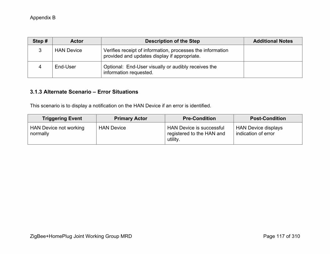
Appendix B
ZigBee+HomePlug Joint Working Group MRD Page 117 of 310
Step # Actor Description of the Step Additional Notes
3 HAN Device Verifies receipt of information, processes the information provided and updates display if appropriate.
4 EndUser Optional: EndUser visually or audibly receives the information requested.
3.1.3 Alternate Scenario – Error Situations
This scenario is to display a notification on the HAN Device if an error is identified.
Triggering Event Primary Actor PreCondition PostCondition
HAN Device not working normally
HAN Device HAN Device is successful registered to the HAN and utility.
HAN Device displays indication of error

Appendix B
ZigBee+HomePlug Joint Working Group MRD Page 118 of 310
3.1.2.1 Steps for this scenario<Describe the normal sequence of events that is required to complete the scenario.>
Step # Actor Description of the Step Additional Notes
# <What Actor, either primary or secondary is responsible for the activity in this step>
<Describe the actions that take place in this step. The step should be described in active, present tense.>
<Elaborate on any additional description or value of the step to help support the descriptions>
1 HAN Device HAN Device is not working normally due to an error, for example:
1. HAN Device failure (e.g. Battery failure)2. HAN Device not communicating with the AMI Meter (e.g. AMI Meter does not respond or acknowledge receipt of messages)
3. HAN Device not communicating with the Utility systems (e.g. could be that the AMI Meter is unable to communicate with Utility, or that the Utility unable to respond to message request)
4. HAN Device is alerted to AMI Meter error.
(refer to SCE C2 #3.6 and 3.7)
Note: error could cause cost information on HAN Device to be out of synchronization with billing system and would need to be corrected.
3 HAN Device Displays visual or audible signal that operation is not normal.
4 EndUser EndUser receives the signal and takes action to correct. This may include contacting the HAN Device vendor or the Utility.
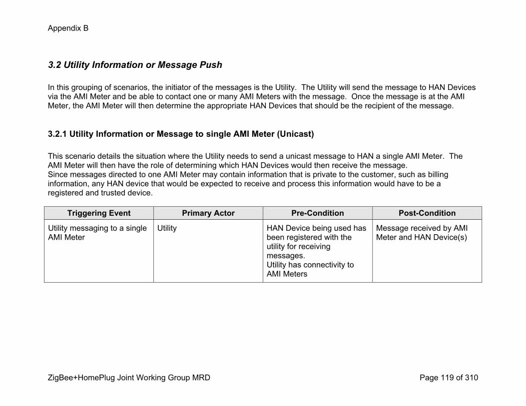
Appendix B
ZigBee+HomePlug Joint Working Group MRD Page 119 of 310
3.2 Utility Information or Message Push
In this grouping of scenarios, the initiator of the messages is the Utility. The Utility will send the message to HAN Devices via the AMI Meter and be able to contact one or many AMI Meters with the message. Once the message is at the AMI Meter, the AMI Meter will then determine the appropriate HAN Devices that should be the recipient of the message.
3.2.1 Utility Information or Message to single AMI Meter (Unicast)
This scenario details the situation where the Utility needs to send a unicast message to HAN a single AMI Meter. The AMI Meter will then have the role of determining which HAN Devices would then receive the message.Since messages directed to one AMI Meter may contain information that is private to the customer, such as billing information, any HAN device that would be expected to receive and process this information would have to be a registered and trusted device.
Triggering Event Primary Actor PreCondition PostCondition
Utility messaging to a single AMI Meter
Utility HAN Device being used has been registered with the utility for receiving messages.Utility has connectivity to AMI Meters
Message received by AMI Meter and HAN Device(s)
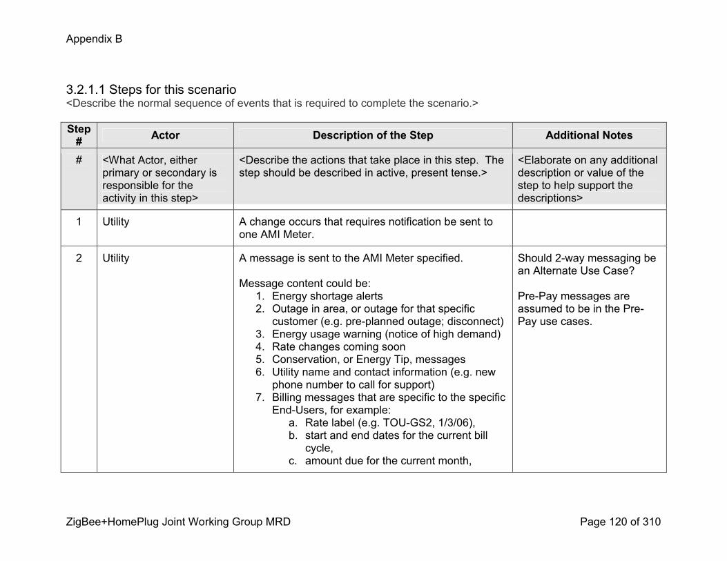
Appendix B
ZigBee+HomePlug Joint Working Group MRD Page 120 of 310
3.2.1.1 Steps for this scenario<Describe the normal sequence of events that is required to complete the scenario.>
Step # Actor Description of the Step Additional Notes
# <What Actor, either primary or secondary is responsible for the activity in this step>
<Describe the actions that take place in this step. The step should be described in active, present tense.>
<Elaborate on any additional description or value of the step to help support the descriptions>
1 Utility A change occurs that requires notification be sent to one AMI Meter.
2 Utility A message is sent to the AMI Meter specified.
Message content could be: 1. Energy shortage alerts 2. Outage in area, or outage for that specific customer (e.g. preplanned outage; disconnect)
3. Energy usage warning (notice of high demand) 4. Rate changes coming soon 5. Conservation, or Energy Tip, messages6. Utility name and contact information (e.g. new phone number to call for support)
7. Billing messages that are specific to the specific EndUsers, for example: a. Rate label (e.g. TOUGS2, 1/3/06), b. start and end dates for the current bill cycle,
c. amount due for the current month,
Should 2way messaging be an Alternate Use Case?
PrePay messages are assumed to be in the PrePay use cases.
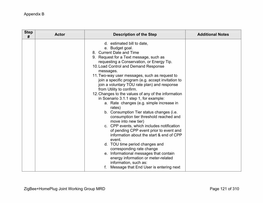
Appendix B
ZigBee+HomePlug Joint Working Group MRD Page 121 of 310
Step # Actor Description of the Step Additional Notes
d. estimated bill to date, e. Budget goal.
8. Current Date and Time 9. Request for a Text message, such as requesting a Conservation, or Energy Tip.
10.Load Control and Demand Response messages.
11.Twoway user messages, such as request to join a specific program (e.g. accept invitation to join a voluntary TOU rate plan) and response from Utility to confirm.
12.Changes to the values of any of the information in Scenario 3.1.1 step 1, for example: a. Rate changes (e.g. simple increase in rates)
b. Consumption Tier status changes (i.e. consumption tier threshold reached and move into new tier)
c. CPP events, which includes notification of pending CPP event prior to event and information about the start & end of CPP event.
d. TOU time period changes and corresponding rate change
e. Informational messages that contain energy information or meterrelated information, such as:
f. Message that End User is entering next
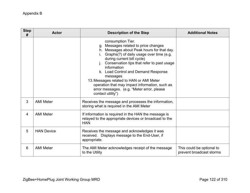
Appendix B
ZigBee+HomePlug Joint Working Group MRD Page 122 of 310
Step # Actor Description of the Step Additional Notes
consumption Tier. g. Messages related to price changesh. Messages about Peak hours for that day. i. Graphs(?) of daily usage over time (e.g. during current bill cycle)
j. Conservation tips that refer to past usage information
k. Load Control and Demand Response messages
13.Messages related to HAN or AMI Meter operation that may impact information, such as error messages. (e.g. “Meter error, please contact utility”)
3 AMI Meter Receives the message and processes the information, storing what is required in the AMI Meter
4 AMI Meter If information is required in the HAN the message is relayed to the appropriate devices or broadcast to the HAN
5 HAN Device Receives the message and acknowledges it was received. Displays message to the EndUser, if appropriate.
6 AMI Meter The AMI Meter acknowledges receipt of the message to the Utility
This could be optional to prevent broadcast storms
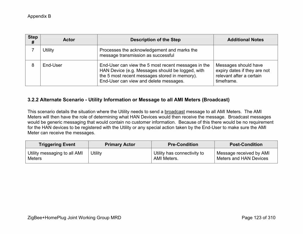
Appendix B
ZigBee+HomePlug Joint Working Group MRD Page 123 of 310
Step # Actor Description of the Step Additional Notes
7 Utility Processes the acknowledgement and marks the message transmission as successful
8 EndUser EndUser can view the 5 most recent messages in the HAN Device (e.g. Messages should be logged, with the 5 most recent messages stored in memory). EndUser can view and delete messages.
Messages should have expiry dates if they are not relevant after a certain timeframe.
3.2.2 Alternate Scenario Utility Information or Message to all AMI Meters (Broadcast)
This scenario details the situation where the Utility needs to send a broadcast message to all AMI Meters. The AMI Meters will then have the role of determining what HAN Devices would then receive the message. Broadcast messages would be generic messaging that would contain no customer information. Because of this there would be no requirement for the HAN devices to be registered with the Utility or any special action taken by the EndUser to make sure the AMI Meter can receive the messages.
Triggering Event Primary Actor PreCondition PostCondition
Utility messaging to all AMI Meters
Utility Utility has connectivity to AMI Meters.
Message received by AMI Meters and HAN Devices

Appendix B
ZigBee+HomePlug Joint Working Group MRD Page 124 of 310
3.2.2.1 Steps for this scenario<Describe the normal sequence of events that is required to complete the scenario.>
Step # Actor Description of the Step Additional Notes
# <What Actor, either primary or secondary is responsible for the activity in this step>
<Describe the actions that take place in this step. The step should be described in active, present tense.>
<Elaborate on any additional description or value of the step to help support the descriptions>
1 Utility A change occurs that requires notification be sent to all AMI Meters.
Message content could be: 1. Energy shortage alerts 2. Outage in area 3. Energy usage warning (notice of high demand) 4. Rate changes coming soon 5. Conservation, or Energy Tip, messages6. Utility contact information (e.g. new phone number to call for support)
7. Billing messages that are generic for all EndUsers. 8. Current Date and Time 9. Flexiblelength Text messages.
Messages must not be restricted to preconfigured or ‘canned’ messages.
2 Utility A broadcast message is sent to the AMI Meters
3 AMI Meter Receives the broadcast message and processes the information
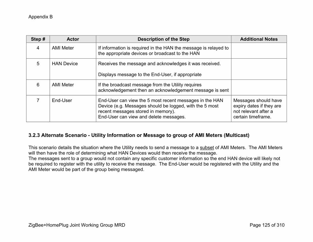
Appendix B
ZigBee+HomePlug Joint Working Group MRD Page 125 of 310
Step # Actor Description of the Step Additional Notes
4 AMI Meter If information is required in the HAN the message is relayed to the appropriate devices or broadcast to the HAN
5 HAN Device Receives the message and acknowledges it was received.
Displays message to the EndUser, if appropriate
6 AMI Meter If the broadcast message from the Utility requires acknowledgement then an acknowledgement message is sent
7 EndUser EndUser can view the 5 most recent messages in the HAN Device (e.g. Messages should be logged, with the 5 most recent messages stored in memory). EndUser can view and delete messages.
Messages should have expiry dates if they are not relevant after a certain timeframe.
3.2.3 Alternate Scenario Utility Information or Message to group of AMI Meters (Multicast)
This scenario details the situation where the Utility needs to send a message to a subset of AMI Meters. The AMI Meters will then have the role of determining what HAN Devices would then receive the message. The messages sent to a group would not contain any specific customer information so the end HAN device will likely not be required to register with the utility to receive the message. The EndUser would be registered with the Utility and the AMI Meter would be part of the group being messaged.
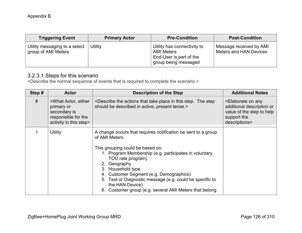
Appendix B
ZigBee+HomePlug Joint Working Group MRD Page 126 of 310
Triggering Event Primary Actor PreCondition PostCondition
Utility messaging to a select group of AMI Meters
Utility Utility has connectivity to AMI MetersEndUser is part of the group being messaged
Message received by AMI Meters and HAN Devices
3.2.3.1 Steps for this scenario<Describe the normal sequence of events that is required to complete the scenario.>
Step # Actor Description of the Step Additional Notes
# <What Actor, either primary or secondary is responsible for the activity in this step>
<Describe the actions that take place in this step. The step should be described in active, present tense.>
<Elaborate on any additional description or value of the step to help support the descriptions>
1 Utility A change occurs that requires notification be sent to a group of AMI Meters.
This grouping could be based on:1. Program Membership (e.g. participates in voluntary TOU rate program)
2. Geography3. Household type4. Customer Segment (e.g. Demographics) 5. Test or Diagnostic message (e.g. could be specific to the HAN Device)
6. Customer group (e.g. several AMI Meters that belong

Appendix B
ZigBee+HomePlug Joint Working Group MRD Page 127 of 310
Step # Actor Description of the Step Additional Notes
to one customer) 7. Distribution system topology (e.g. substation)
2 Utility A message is sent to the appropriate group of AMI Meters.
Message content could be: 1. Energy shortage alerts 2. Outage in area 3. Energy usage warning (notice of high demand) 4. Rate changes coming soon 5. Conservation, or Energy Tip, messages6. Utility contact information (e.g. new phone number to call for support)
7. Billing messages that are generic for this group 8. Current Date and Time 9. Free form messages 10.Load Control and Demand Response messages.
Refer to Prepaid Use Cases for prepaid messages.
Budget Goal: Customer is able to set a target budget goal (dollars or percentage reduction) for the device to track to.
3 AMI Meter Receives the group message and processes the information
4 AMI Meter If information is required in the HAN the message is relayed to the appropriate devices or broadcast to the HAN
5 HAN Device Receives the message and acknowledges it was received.
Displays message to the EndUser if appropriate

Appendix B
ZigBee+HomePlug Joint Working Group MRD Page 128 of 310
Step # Actor Description of the Step Additional Notes
6 AMI Meter If the group message from the Utility requires acknowledgement then an acknowledgement message is sent
7 EndUser EndUser can view the 5 most recent messages in the HAN Device (e.g. Messages should be logged, with the 5 most recent messages stored in memory). EndUser can view and delete messages.
Messages should have expiry dates if they are not relevant after a certain timeframe.
3.2.4 Alternate Scenario – Error Situations SAME AS 3.1.3
3.2.5 Alternate Scenario – Twoway messaging ! Incremental step to Scenarios 3.2.1, 3.2.2, and 3.2.3 where EndUser interaction required, such as joining a program or can override a nonemergency curtailment request.
4. Requirements<Describe the Functional, NonFunctional and Business Requirements generated from the workshop in the tables below. If applicable list the associated use case scenario and step.>
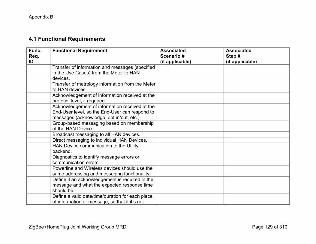
Appendix B
ZigBee+HomePlug Joint Working Group MRD Page 129 of 310
4.1 Functional Requirements
Func.Req.ID
Functional Requirement AssociatedScenario #(if applicable)
AssociatedStep #(if applicable)
Transfer of information and messages (specified in the Use Cases) from the Meter to HAN devices. Transfer of metrology information from the Meter to HAN devices. Acknowledgement of information received at the protocol level, if required. Acknowledgement of information received at the EndUser level, so the EndUser can respond to messages (acknowledge, opt in/out, etc.). Groupbased messaging based on membership of the HAN Device. Broadcast messaging to all HAN devices. Direct messaging to individual HAN Devices.HAN Device communication to the Utility backend.Diagnostics to identify message errors or communication errors. Powerline and Wireless devices should use the same addressing and messaging functionality. Define if an acknowledgement is required in the message and what the expected response time should be. Define a valid date/time/duration for each piece of information or message, so that if it’s not

Appendix B
ZigBee+HomePlug Joint Working Group MRD Page 130 of 310
acted on or responded to it expires. Also used for displaying new information based on scheduled changes to information.
4.2 NonFunctional Requirements
Nonfunc.Req.ID
NonFunctional Requirement AssociatedScenario #(if applicable)
AssociatedStep #(if applicable)
Near realtime message supportVerification of received messagesBattery powered devices should not require battery replacement for at least 2 yearsDirect Utility to HAN Device communication without need for a gatewayMessages expire if a newer message of the same type is receivedVariable length messages supportedMultiple languages supportedImperial and Metric unitsFormatted text to support display to EndUser on varying types of HAN Devices
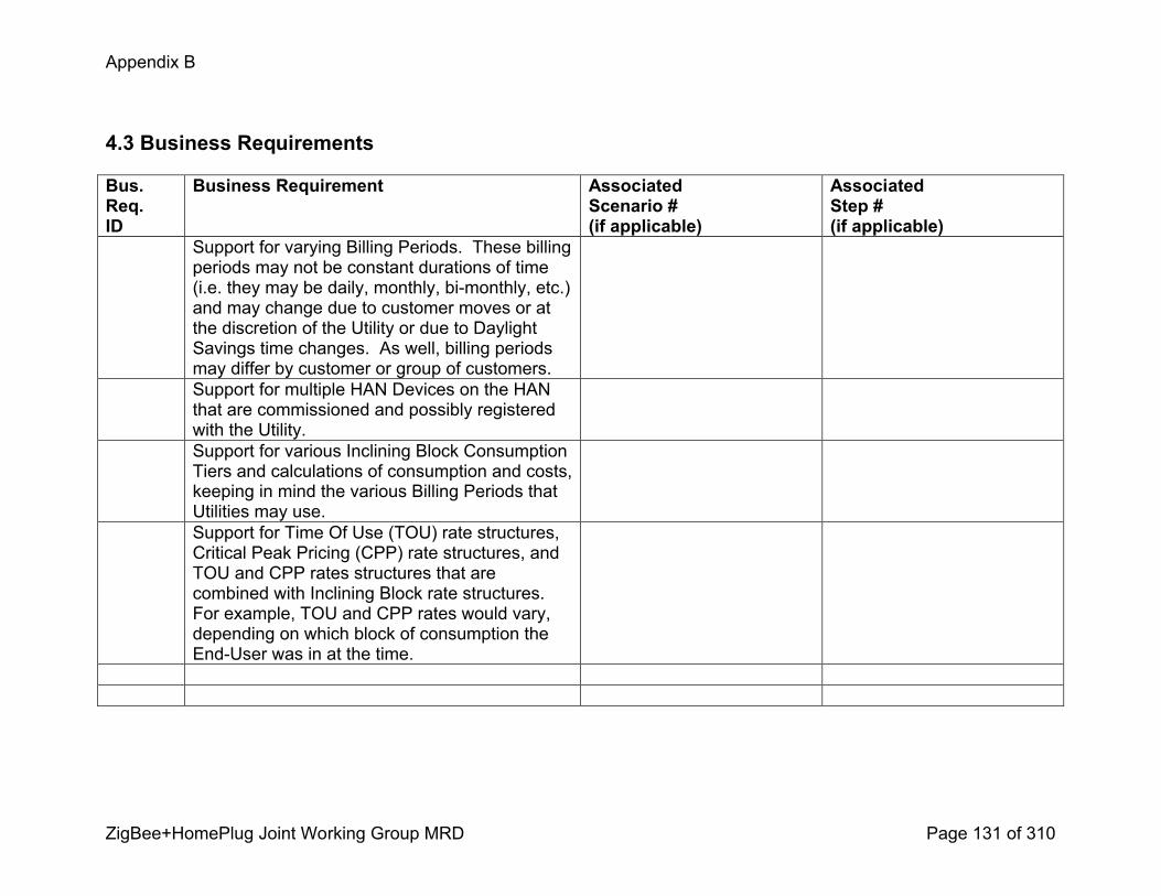
Appendix B
ZigBee+HomePlug Joint Working Group MRD Page 131 of 310
4.3 Business Requirements
Bus.Req.ID
Business Requirement AssociatedScenario #(if applicable)
AssociatedStep #(if applicable)
Support for varying Billing Periods. These billing periods may not be constant durations of time (i.e. they may be daily, monthly, bimonthly, etc.) and may change due to customer moves or at the discretion of the Utility or due to Daylight Savings time changes. As well, billing periods may differ by customer or group of customers.Support for multiple HAN Devices on the HAN that are commissioned and possibly registered with the Utility. Support for various Inclining Block Consumption Tiers and calculations of consumption and costs, keeping in mind the various Billing Periods that Utilities may use. Support for Time Of Use (TOU) rate structures, Critical Peak Pricing (CPP) rate structures, and TOU and CPP rates structures that are combined with Inclining Block rate structures. For example, TOU and CPP rates would vary, depending on which block of consumption the EndUser was in at the time.

Appendix B
ZigBee+HomePlug Joint Working Group MRD Page 132 of 310
User Information and Messages Use Cases
Management Messages
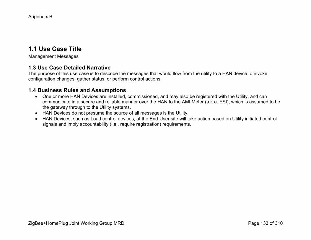
Appendix B
ZigBee+HomePlug Joint Working Group MRD Page 133 of 310
1.1 Use Case TitleManagement Messages
1.3 Use Case Detailed NarrativeThe purpose of this use case is to describe the messages that would flow from the utility to a HAN device to invoke configuration changes, gather status, or perform control actions.
1.4 Business Rules and Assumptions! One or more HAN Devices are installed, commissioned, and may also be registered with the Utility, and can communicate in a secure and reliable manner over the HAN to the AMI Meter (a.k.a. ESI), which is assumed to be the gateway through to the Utility systems.
! HAN Devices do not presume the source of all messages is the Utility. ! HAN Devices, such as Load control devices, at the EndUser site will take action based on Utility initiated control signals and imply accountability (i.e., require registration) requirements.
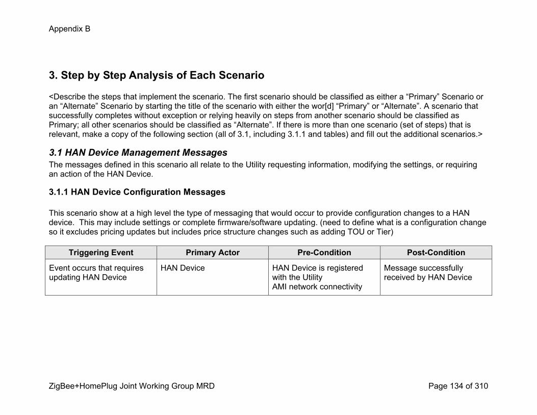
Appendix B
ZigBee+HomePlug Joint Working Group MRD Page 134 of 310
3. Step by Step Analysis of Each Scenario
<Describe the steps that implement the scenario. The first scenario should be classified as either a “Primary” Scenario or an “Alternate” Scenario by starting the title of the scenario with either the wor[d] “Primary” or “Alternate”. A scenario that successfully completes without exception or relying heavily on steps from another scenario should be classified as Primary; all other scenarios should be classified as “Alternate”. If there is more than one scenario (set of steps) that is relevant, make a copy of the following section (all of 3.1, including 3.1.1 and tables) and fill out the additional scenarios.>
3.1 HAN Device Management MessagesThe messages defined in this scenario all relate to the Utility requesting information, modifying the settings, or requiring an action of the HAN Device.
3.1.1 HAN Device Configuration Messages
This scenario show at a high level the type of messaging that would occur to provide configuration changes to a HAN device. This may include settings or complete firmware/software updating. (need to define what is a configuration change so it excludes pricing updates but includes price structure changes such as adding TOU or Tier)
Triggering Event Primary Actor PreCondition PostCondition
Event occurs that requires updating HAN Device
HAN Device HAN Device is registered with the UtilityAMI network connectivity
Message successfully received by HAN Device

Appendix B
ZigBee+HomePlug Joint Working Group MRD Page 135 of 310
3.1.1 Steps for this scenario<Describe the normal sequence of events that is required to complete the scenario.>
Step # Actor Description of the Step Additional Notes
# <What Actor, either primary or secondary is responsible for the activity in this step>
<Describe the actions that take place in this step. The step should be described in active, present tense.>
<Elaborate on any additional description or value of the step to help support the descriptions>
1 Utility Updates information that will require a change to the configuration of HAN Devices.
This could include: 1. Changes to rate structures, for example:
a. Addition/deletion of a Tier in a tiered usage program
b. Addition/Deletion of a TOU time period2. Changes to HAN Device behaviour, for example:
a. EndUser joins a voluntary load control program and the HAN Device needs a configuration change to enable different functionality on the HAN Device
3. New firmware/software upgrade to HAN Device 4. Changes to time due to Daylight Savings Time 5. Other?
2 Utility Message is sent to the HAN Device for configuration change via the AMI Meter
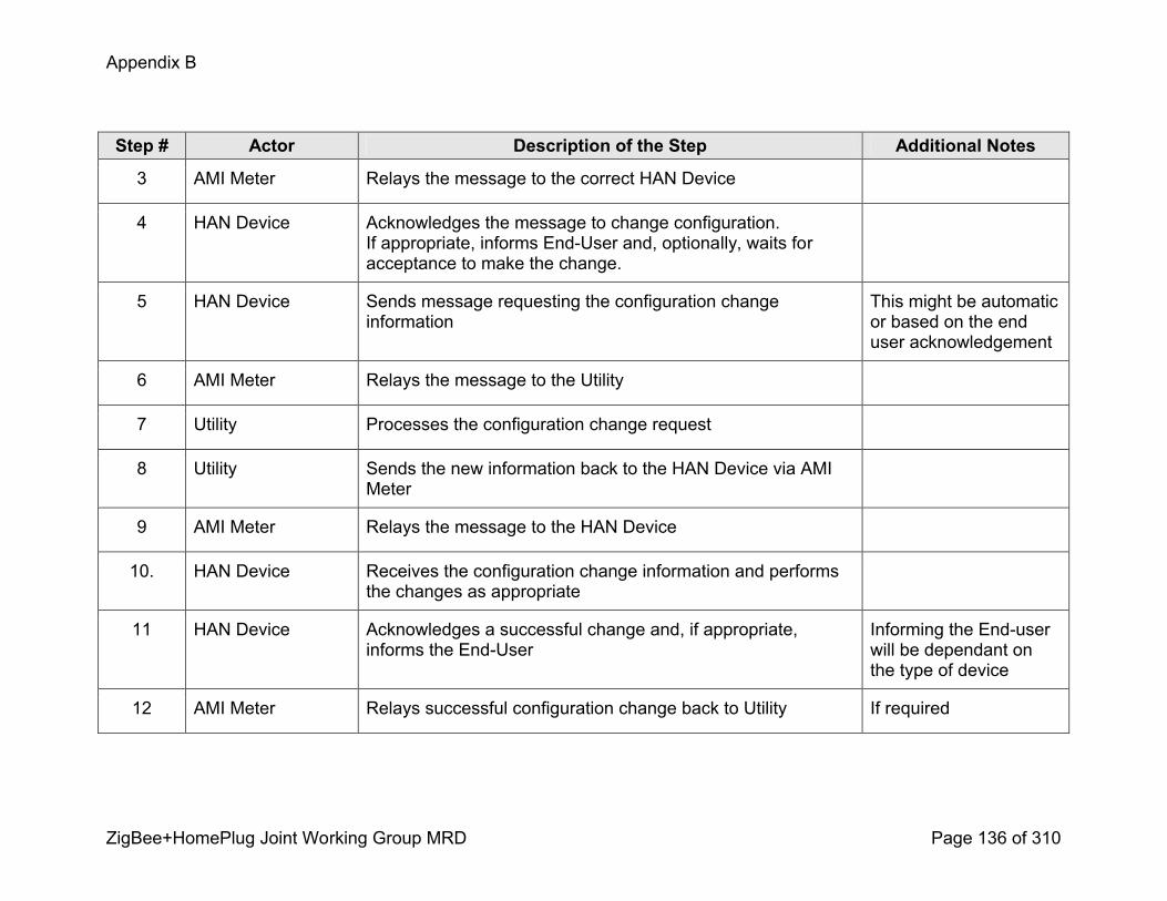
Appendix B
ZigBee+HomePlug Joint Working Group MRD Page 136 of 310
Step # Actor Description of the Step Additional Notes
3 AMI Meter Relays the message to the correct HAN Device
4 HAN Device Acknowledges the message to change configuration. If appropriate, informs EndUser and, optionally, waits for acceptance to make the change.
5 HAN Device Sends message requesting the configuration change information
This might be automatic or based on the end user acknowledgement
6 AMI Meter Relays the message to the Utility
7 Utility Processes the configuration change request
8 Utility Sends the new information back to the HAN Device via AMI Meter
9 AMI Meter Relays the message to the HAN Device
10. HAN Device Receives the configuration change information and performs the changes as appropriate
11 HAN Device Acknowledges a successful change and, if appropriate, informs the EndUser
Informing the Enduser will be dependant on the type of device
12 AMI Meter Relays successful configuration change back to Utility If required

Appendix B
ZigBee+HomePlug Joint Working Group MRD Page 137 of 310
Step # Actor Description of the Step Additional Notes
13 Utility Processes the successful configuration change, if needed
3.1.2 Alternate Scenario HAN Device Status MessagesThis scenario describes the ability of the AMI system to get status messages from registered HAN devices to determine participation in voluntary events or just the general functioning of the device.
Triggering Event Primary Actor PreCondition PostCondition
Utility requires status from the HAN Device
HAN Device HAN Device is registered with the UtilityAMI network connectivity
Message successfully received by the HAN Device.
3.1.2.1 Steps for this scenario<Describe the normal sequence of events that is required to complete the scenario.>
Step # Actor Description of the Step Additional Notes
# <What Actor, either primary or secondary is responsible for the activity in this step>
<Describe the actions that take place in this step. The step should be described in active, present tense.>
<Elaborate on any additional description or value of the step to help support the descriptions>
1 Utility Determines the need to query one or more HAN Devices to determine status or events on the device(s) Direct to HAN Device
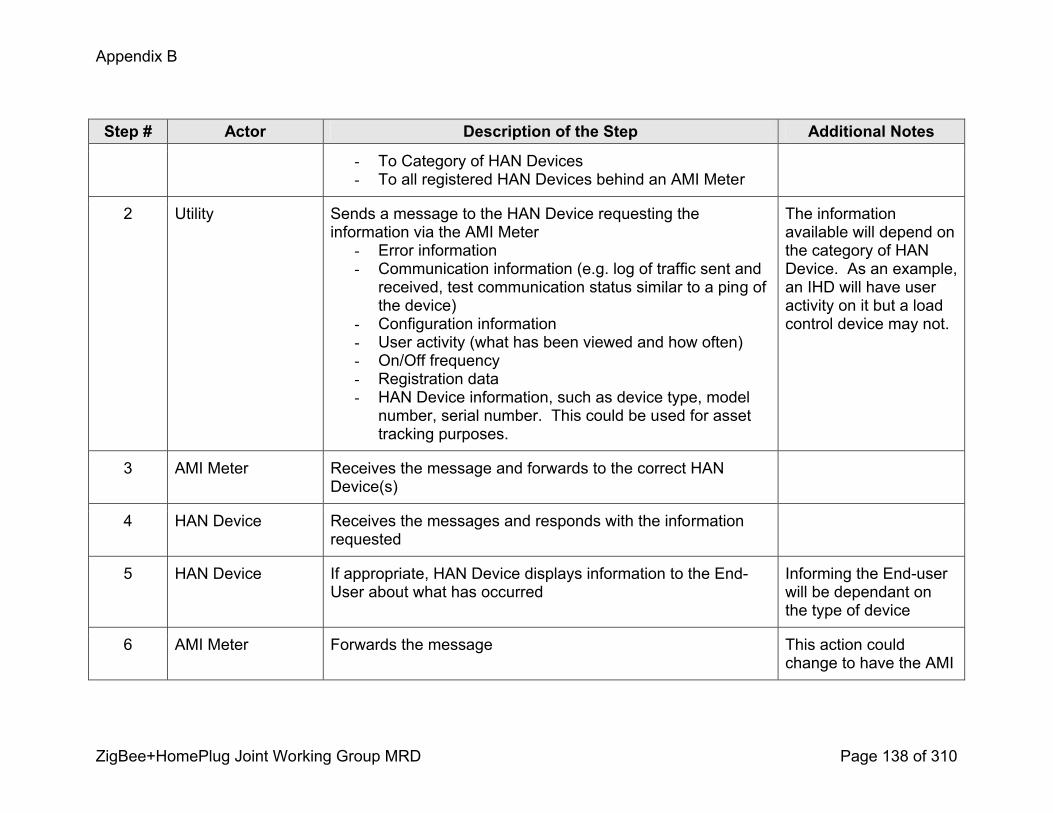
Appendix B
ZigBee+HomePlug Joint Working Group MRD Page 138 of 310
Step # Actor Description of the Step Additional Notes
To Category of HAN Devices To all registered HAN Devices behind an AMI Meter
2 Utility Sends a message to the HAN Device requesting the information via the AMI Meter Error information Communication information (e.g. log of traffic sent and received, test communication status similar to a ping of the device)
Configuration information User activity (what has been viewed and how often) On/Off frequency Registration data HAN Device information, such as device type, model number, serial number. This could be used for asset tracking purposes.
The information available will depend on the category of HAN Device. As an example, an IHD will have user activity on it but a load control device may not.
3 AMI Meter Receives the message and forwards to the correct HAN Device(s)
4 HAN Device Receives the messages and responds with the information requested
5 HAN Device If appropriate, HAN Device displays information to the EndUser about what has occurred
Informing the Enduser will be dependant on the type of device
6 AMI Meter Forwards the message This action could change to have the AMI
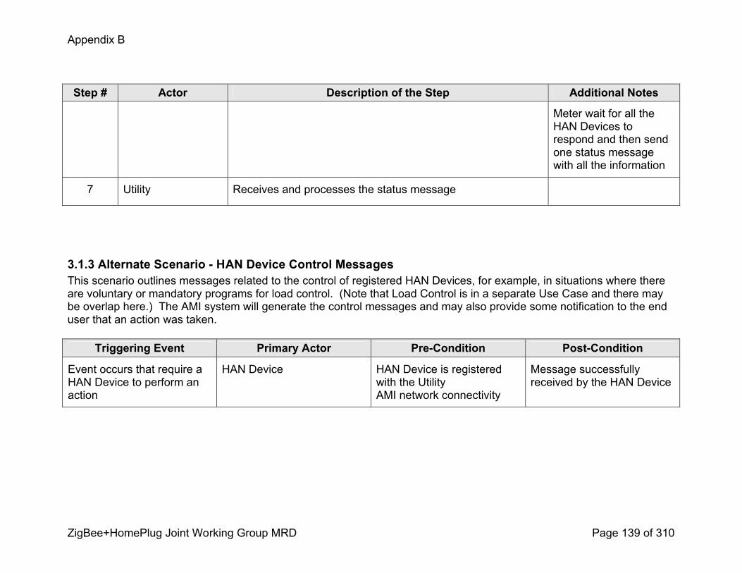
Appendix B
ZigBee+HomePlug Joint Working Group MRD Page 139 of 310
Step # Actor Description of the Step Additional Notes
Meter wait for all the HAN Devices to respond and then send one status message with all the information
7 Utility Receives and processes the status message
3.1.3 Alternate Scenario HAN Device Control Messages This scenario outlines messages related to the control of registered HAN Devices, for example, in situations where there are voluntary or mandatory programs for load control. (Note that Load Control is in a separate Use Case and there may be overlap here.) The AMI system will generate the control messages and may also provide some notification to the end user that an action was taken.
Triggering Event Primary Actor PreCondition PostCondition
Event occurs that require a HAN Device to perform an action
HAN Device HAN Device is registered with the UtilityAMI network connectivity
Message successfully received by the HAN Device
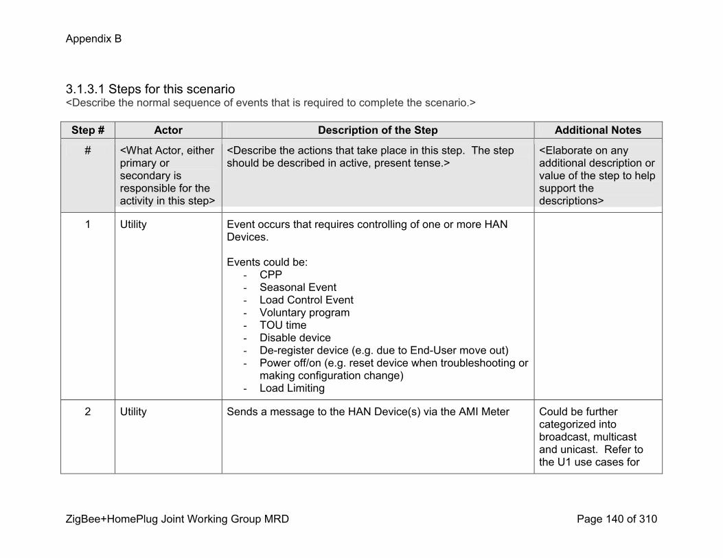
Appendix B
ZigBee+HomePlug Joint Working Group MRD Page 140 of 310
3.1.3.1 Steps for this scenario<Describe the normal sequence of events that is required to complete the scenario.>
Step # Actor Description of the Step Additional Notes
# <What Actor, either primary or secondary is responsible for the activity in this step>
<Describe the actions that take place in this step. The step should be described in active, present tense.>
<Elaborate on any additional description or value of the step to help support the descriptions>
1 Utility Event occurs that requires controlling of one or more HAN Devices.
Events could be: CPP Seasonal Event Load Control Event Voluntary program TOU time Disable device Deregister device (e.g. due to EndUser move out) Power off/on (e.g. reset device when troubleshooting or making configuration change)
Load Limiting
2 Utility Sends a message to the HAN Device(s) via the AMI Meter Could be further categorized into broadcast, multicast and unicast. Refer to the U1 use cases for

Appendix B
ZigBee+HomePlug Joint Working Group MRD Page 141 of 310
Step # Actor Description of the Step Additional Notes
different methods of Utility to AMI Meter methods of messaging
3 AMI Meter Receives the message and relays it to the correct HAN Device(s)
4 HAN Device Receives the messages and optionally, displays information to the EndUser
Informing the Enduser will be dependant on the type of device
5 EndUser OPTIONAL: May have the opportunity to opt in or opt out of the control event by pressing a button on the HAN Device.
If applicable, may be a twoway message.
6 HAN Device Performs the required action.
7 HAN Device Acknowledges the message and that the action has happened, the acknowledgement is sent via the AMI Meter
If the action is to turn off then the reply will be sent prior to turning off
8 HAN Device If appropriate, HAN Device displays information to the EndUser about what has occurred
9 AMI Meter Sends message to Utility that the action is complete This action could change to have the AMI Meter wait for all the HAN Devices to respond and then send one status message
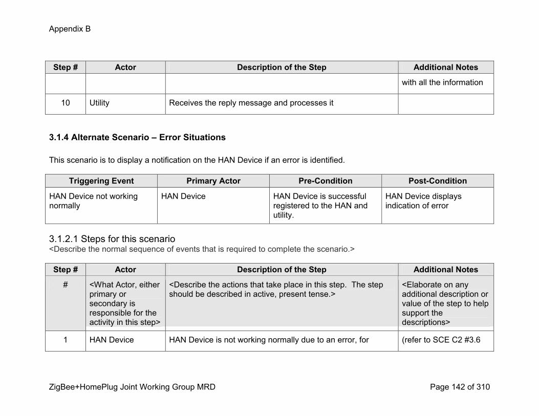
Appendix B
ZigBee+HomePlug Joint Working Group MRD Page 142 of 310
Step # Actor Description of the Step Additional Notes
with all the information
10 Utility Receives the reply message and processes it
3.1.4 Alternate Scenario – Error Situations
This scenario is to display a notification on the HAN Device if an error is identified.
Triggering Event Primary Actor PreCondition PostCondition
HAN Device not working normally
HAN Device HAN Device is successful registered to the HAN and utility.
HAN Device displays indication of error
3.1.2.1 Steps for this scenario<Describe the normal sequence of events that is required to complete the scenario.>
Step # Actor Description of the Step Additional Notes
# <What Actor, either primary or secondary is responsible for the activity in this step>
<Describe the actions that take place in this step. The step should be described in active, present tense.>
<Elaborate on any additional description or value of the step to help support the descriptions>
1 HAN Device HAN Device is not working normally due to an error, for (refer to SCE C2 #3.6

Appendix B
ZigBee+HomePlug Joint Working Group MRD Page 143 of 310
Step # Actor Description of the Step Additional Notes
example:
5. HAN Device failure (e.g. Battery failure)6. HAN Device not communicating with the AMI Meter (e.g. AMI Meter does not respond or acknowledge receipt of messages)
7. HAN Device not communicating with the Utility systems (e.g. could be that the AMI Meter is unable to communicate with Utility, or that the Utility unable to respond to message request)
8. HAN Device is alerted to AMI Meter error. 9. HAN Device unable to upgrade.
and 3.7)
Note: error could cause cost information on HAN Device to be out of synchronization with billing system and would need to be corrected.
3 HAN Device Displays visual or audible signal that operation is not normal.
4 EndUser EndUser receives the signal and takes action to correct. This may include contacting the HAN Device vendor or the Utility.
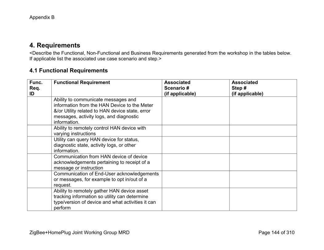
Appendix B
ZigBee+HomePlug Joint Working Group MRD Page 144 of 310
4. Requirements<Describe the Functional, NonFunctional and Business Requirements generated from the workshop in the tables below. If applicable list the associated use case scenario and step.>
4.1 Functional Requirements
Func.Req.ID
Functional Requirement AssociatedScenario #(if applicable)
AssociatedStep #(if applicable)
Ability to communicate messages and information from the HAN Device to the Meter &/or Utility related to HAN device state, error messages, activity logs, and diagnostic information. Ability to remotely control HAN device with varying instructionsUtility can query HAN device for status, diagnostic state, activity logs, or other information. Communication from HAN device of device acknowledgements pertaining to receipt of a message or instructionCommunication of EndUser acknowledgements or messages, for example to opt in/out of a request. Ability to remotely gather HAN device asset tracking information so utility can determine type/version of device and what activities it can perform

Appendix B
ZigBee+HomePlug Joint Working Group MRD Page 145 of 310
Ability to update rate structures, pricing, and other details about rates, including expiration/validity information on HAN Devices. Ability to send messages to remotely power on and off a HAN Device, or to deregister a HAN Device. Ability to send messages to deregister a HAN Device.Ability for messages from AMI Meter to be sent to a group or category of HAN devices.
4.2 NonFunctional Requirements
Nonfunc.Req.ID
NonFunctional Requirement AssociatedScenario #(if applicable)
AssociatedStep #(if applicable)
Supports multiple languagesVariable message lengthSecure messagesEach HAN device uniquely addressableHAN Devices can be upgradedMessage urgency can be definedAMI Meter can buffer low priority messages for bulk send to utilityHigh priority messages are sent back to the utility quickly (define a time)HAN device can recover from a bad firmware/software upgrade
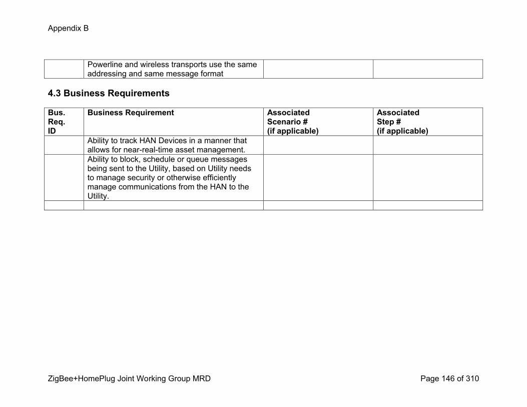
Appendix B
ZigBee+HomePlug Joint Working Group MRD Page 146 of 310
Powerline and wireless transports use the same addressing and same message format
4.3 Business Requirements
Bus.Req.ID
Business Requirement AssociatedScenario #(if applicable)
AssociatedStep #(if applicable)
Ability to track HAN Devices in a manner thatallows for nearrealtime asset management. Ability to block, schedule or queue messages being sent to the Utility, based on Utility needs to manage security or otherwise efficiently manage communications from the HAN to the Utility.

Appendix B
ZigBee+HomePlug Joint Working Group MRD Page 147 of 310
PEV Use Cases

Appendix B
ZigBee+HomePlug Joint Working Group MRD Page 148 of 310
a. PEV Use Case 0 Customer enrolls in PHEV program, completes initial setup for PEV and implements connection and charging cycles
Use Case TitlePEV – Customer AttributesCustomer enrolls in PHEV program, completes initial setup for PEV and implements connection and charging cycles.
Use Case SummaryCustomers, Vehicle Manufacturers (VM) and Utilities are interested in fueling vehicles with electricity. Electric Vehicles (EV), Plugin Vehicles (PEV) and Plugin Hybrid Vehicles (PHEV) are emerging transportation options for consumers. Electric utilities desire to support these emerging loads with electricity at times when energy costs are lower and generation and power delivery assets are underutilized. PEV manufacturers are interested in working with utilities to develop customer rates/programs which could provide consumers with an increased incentive to purchase a PEV. To enable utility customer rates/programs specifically to customers with PEVs, the utility must offer special services for these customers. These services include the ability to enroll, register, and initially setup communications between a PEV and the utility, or an Alternative Energy Supplier (AES) (onetime setup), the ability to repeatedly reestablish communications for each PEV charging session (repeat communications/rebinding), the ability to provide PEV charging (and other) status information to customer information channels (e.g. web, display devices), and the ability to correctly bill PEV customers according to their selected rates/programs.
Use Case Detailed NarrativeThe Utility or AES, may offer the Customer a tariff that provides a low rate for offpeak charging and a higher rate for onpeak charging. The utility or AES must provide services to support energy supplied to customer PEV. These services include enrollment into a PEV program, PEV communications session binding, PEV energy billing, and PEV information services. The utility or AES will implement an enrollment system for Customers with a PEV including registration and commissioning. The utility’s or AES's Energy Services Communication Interface (ESCI) shall allow for the establishment of a communications session (communications binding), at a premise location each time a PEV plugs in for charging. Energy supplied to the PEV is reported to the utility or AES,
Appendix B
ZigBee+HomePlug Joint Working Group MRD Page 149 of 310
for billing and presentation to the Customer. The following scenarios describe the sequence of events for this customer to utility interface:
1) E: Basic Enrollment: General Registration/Enrollment Steps and Initial Setup for PEVUtility Authorization & Authentication2) U: Specific Enrollment: Utility Programs (Awareness, etc.)3) S: PEV Connection and Energy Transfer: Binding/Rebinding (Startup, PEV Authentication, Basic Charging per enrolled program, Communication & Shutdown)4) L: Location variations: Connection Location (PEV Authentication, Basic Charging per enrolled program)5) PR: Specific Functions: Charging, Discharging, Diagnostics and VM Specific applications.
Business Rules and Assumptions! PEV Customer has an account with utility and electrical service at a premise served by the utility.
! PEV and utility may have communications capabilities, enabled by utility provided Energy Services Communication Interface (ESCI).
! The customer awareness of the utility and vehicle programs is prompted by both the utility providers and the vehicle manufacturers.
! The utility offers PEV programs and services for its customers and will provide the necessary support processes for enrollment, communications, and billing
! The Vehicle manufacturers would provide information to the customer about fuel and/or emission gains of the vehicles offered and promote the utility and convenience of connecting to the grid
! Utility shall maintain information on all Customers and PEVs enrolled in the PEV programs, including demand side management programs, associated PEV IDs, customer IDs, and premise IDs.
! In the absence or failure of PEV-utility communications, or if PEV ID validation fails, PEV charging will always proceed; however, without the incentive rates and with all energy charges accruing to the premise customer according to the premise customer’s default rate/service plan.
! The actual PEV charging processes, including scenarios for intra- and inter- utility roaming, are covered in use case P2.

Appendix B
ZigBee+HomePlug Joint Working Group MRD Page 150 of 310
! End Use Measurement Device (EUMD), either fixed or mobile, is always available for energy validation of PEV charging. If not available, charging will proceed, but with limitations on incentive rates and with all energy charges accruing to the premise customer. This may or may not prevent certain charging status indicators / metrics being available to customer for presentation/display purposes.
! EUMD function can be inclusively located anywhere in a zone from the PEV and the branch circuit panel connection.
! To allow for possibility of the EUMD being a part of/within the PEV, PEV is a sub-meter to the primary utility billing meter at any premise (as opposed to being a separate service account with dual meter socket adapter)
! The PEV & Utility will communicate to implement one or more the previously described Utility programs (details of which are covered in section 3.3).
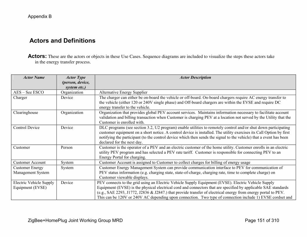
Appendix B
ZigBee+HomePlug Joint Working Group MRD Page 151 of 310
Actors and Definitions
Actors: These are the actors or objects in these Use Cases. Sequence diagrams are included to visualize the steps these actors take in the energy transfer process.
Actor Name Actor Type (person, device, system etc.)
Actor Description
AES – See ESCO Organization Alternative Energy SupplierCharger Device The charger can either be onboard the vehicle or offboard. Onboard chargers require AC energy transfer to
the vehicle (either 120 or 240V single phase) and Offboard chargers are within the EVSE and require DC energy transfer to the vehicle.
Clearinghouse Organization Organization that provides global PEV account services. Maintains information necessary to facilitate account validation and billing transaction when Customer is charging PEV at a location not served by the Utility that the Customer is enrolled with.
Control Device Device DLC programs (see section 3.2, U2 program) enable utilities to remotely control and/or shut down participating customer equipment on a short notice. A control device is installed. The utility exercises its Call Option by first notifying the participant (to the control device which then sends the signal to the vehicle) that a event has been declared for the next day.
Customer Person Customer is the operator of a PEV and an electric customer of the home utility. Customer enrolls in an electric utility PEV program and has selected a PEV rate tariff. Customer is responsible for connecting PEV to an Energy Portal for charging.
Customer Account System Customer Account is assigned to Customer to collect charges for billing of energy usageCustomer Energy Management System
System Customer Energy Management System can provide communication interface to PEV for communication of PEV status information (e.g. charging state, stateofcharge, charging rate, time to complete charge) on Customer viewable displays.
Electric Vehicle Supply Equipment (EVSE)
Device PEV connects to the grid using an Electric Vehicle Supply Equipment (EVSE). Electric Vehicle Supply Equipment (EVSE) is the physical electrical cord and connectors that are specified by applicable SAE standards (e.g., SAE 2293, J1772, J2836 & J2847.) that provide transfer of electrical energy from energy portal to PEV. This can be 120V or 240V AC depending upon connection. Two type of connection include 1) EVSE cordset and
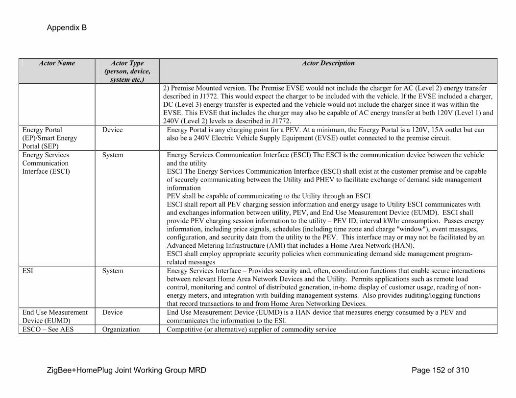
Appendix B
ZigBee+HomePlug Joint Working Group MRD Page 152 of 310
Actor Name Actor Type (person, device, system etc.)
Actor Description
2) Premise Mounted version. The Premise EVSE would not include the charger for AC (Level 2) energy transfer described in J1772. This would expect the charger to be included with the vehicle. If the EVSE included a charger, DC (Level 3) energy transfer is expected and the vehicle would not include the charger since it was within the EVSE. This EVSE that includes the charger may also be capable of AC energy transfer at both 120V (Level 1) and 240V (Level 2) levels as described in J1772.
Energy Portal (EP)/Smart Energy Portal (SEP)
Device Energy Portal is any charging point for a PEV. At a minimum, the Energy Portal is a 120V, 15A outlet but can also be a 240V Electric Vehicle Supply Equipment (EVSE) outlet connected to the premise circuit.
Energy Services Communication Interface (ESCI)
System Energy Services Communication Interface (ESCI) The ESCI is the communication device between the vehicle and the utilityESCI The Energy Services Communication Interface (ESCI) shall exist at the customer premise and be capable of securely communicating between the Utility and PHEV to facilitate exchange of demand side management informationPEV shall be capable of communicating to the Utility through an ESCIESCI shall report all PEV charging session information and energy usage to Utility ESCI communicates with and exchanges information between utility, PEV, and End Use Measurement Device (EUMD). ESCI shall provide PEV charging session information to the utility – PEV ID, interval kWhr consumption. Passes energy information, including price signals, schedules (including time zone and charge "window"), event messages, configuration, and security data from the utility to the PEV. This interface may or may not be facilitated by an Advanced Metering Infrastructure (AMI) that includes a Home Area Network (HAN). ESCI shall employ appropriate security policies when communicating demand side management programrelated messages
ESI System Energy Services Interface – Provides security and, often, coordination functions that enable secure interactions between relevant Home Area Network Devices and the Utility. Permits applications such as remote load control, monitoring and control of distributed generation, inhome display of customer usage, reading of nonenergy meters, and integration with building management systems. Also provides auditing/logging functions that record transactions to and from Home Area Networking Devices.
End Use Measurement Device (EUMD)
Device End Use Measurement Device (EUMD) is a HAN device that measures energy consumed by a PEV and communicates the information to the ESI.
ESCO – See AES Organization Competitive (or alternative) supplier of commodity service
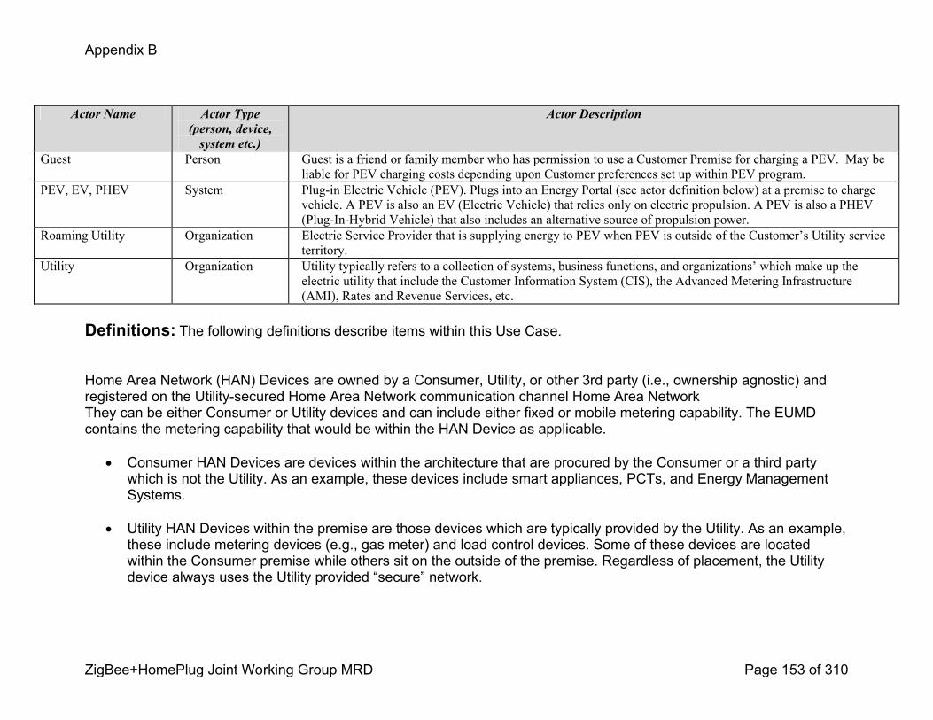
Appendix B
ZigBee+HomePlug Joint Working Group MRD Page 153 of 310
Actor Name Actor Type (person, device, system etc.)
Actor Description
Guest Person Guest is a friend or family member who has permission to use a Customer Premise for charging a PEV. May be liable for PEV charging costs depending upon Customer preferences set up within PEV program.
PEV, EV, PHEV System Plugin Electric Vehicle (PEV). Plugs into an Energy Portal (see actor definition below) at a premise to charge vehicle. A PEV is also an EV (Electric Vehicle) that relies only on electric propulsion. A PEV is also a PHEV (PlugInHybrid Vehicle) that also includes an alternative source of propulsion power.
Roaming Utility Organization Electric Service Provider that is supplying energy to PEV when PEV is outside of the Customer’s Utility service territory.
Utility Organization Utility typically refers to a collection of systems, business functions, and organizations’ which make up the electric utility that include the Customer Information System (CIS), the Advanced Metering Infrastructure (AMI), Rates and Revenue Services, etc.
Definitions: The following definitions describe items within this Use Case.
Home Area Network (HAN) Devices are owned by a Consumer, Utility, or other 3rd party (i.e., ownership agnostic) and registered on the Utilitysecured Home Area Network communication channel Home Area NetworkThey can be either Consumer or Utility devices and can include either fixed or mobile metering capability. The EUMD contains the metering capability that would be within the HAN Device as applicable.
! Consumer HAN Devices are devices within the architecture that are procured by the Consumer or a third party which is not the Utility. As an example, these devices include smart appliances, PCTs, and Energy Management Systems.
! Utility HAN Devices within the premise are those devices which are typically provided by the Utility. As an example, these include metering devices (e.g., gas meter) and load control devices. Some of these devices are located within the Consumer premise while others sit on the outside of the premise. Regardless of placement, the Utility device always uses the Utility provided “secure” network.
Appendix B
ZigBee+HomePlug Joint Working Group MRD Page 154 of 310
! Some devices can be provided by either the Utility or the consumer. This decision is between the consumer, Utility, and regulators. Further, this document provides architecture flexibility. That is, the UtilityAMI 2008 HAN SRS supports any desired configuration.
! The Fixed HAN Devices with Metering Capability (FHDMC) connects with the premise HAN and identifies itself and the account it is properly associated with to the Utility, where premise owner’s charges are reconciled. This use case also describes the scenario documented in The Load and Energy Management Use Cases, in that the FHDMC may behave according to that use case. The following scenario is defined: bidirectional metering (i.e., distributed generation) and thirdparty (i.e., gas meter).
! The Mobile HAN Devices with Metering Capability MHDMC connects with the premise Home Area Network (HAN), identifies itself and the account it is properly associated with the Utility. MHDMC’s and premise owner’s charges are reconciled, as applicable. This use case also describes the scenario documented in The Load and Energy Management Use Cases, in that the MHDMC may behave according to that use case. The mobile (e.g. any Consumer PHEV/EV) scenario is defined in this document.
! Energy Cost applications are not intended to reconcile costs displayed on HAN Devices with bills generated by a Utility billing system. There are other elements associated with billing and revenuegrade metering that are outside the scope of these requirements (e.g., revenuegrade certification, rate recovery).
Rechargeable Energy Storage System (RESS): Any energy storage system that has the capability to be charged and discharged (example: batteries, capacitors, and electro mechanical flywheels).
State of Charge (SOC): The ratio of available capacity as compared to the total capacity of an RESS.
Step by Step Analysis of Each Scenario

Appendix B
ZigBee+HomePlug Joint Working Group MRD Page 155 of 310
Scenario Description
E: Basic EnrollmentPurpose: Utility provides services to Plugin Electric Vehicle (PEV) Customer. To enable utility customer rates/programs specifically to customers with PEVs, the utility must offer special services for these customers. These services include the ability to enroll, register, and initially setup the utility programs (onetime setup).
This scenario describes the most common sequence (basic process) of the utility enrolling a PEV customer into a utility program/ service specifically for customers with PEVs. This involves basic enrollment of the PEV.
Triggering Event Primary Actor PreCondition PostCondition
The Customer acquires a PEV and
contacts the Utility to enroll in a
PEV program.
The customer may be prompted by
the dealer, VM, retail store, utility
and more in the awareness cycle.
Customer Customer has a PEV and wishes
to enroll in PEV program; Utility
offers PEV Programs to its
customers.
Customer then selects specific
utility programs offered within the
territory or the vehicle travel
area.
Steps for this scenario
Step # Actor Description of the Step Additional Notes
1 Customer Customer is presented by the Utility with PEV Program information and PEV Program selections.
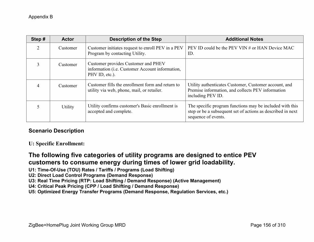
Appendix B
ZigBee+HomePlug Joint Working Group MRD Page 156 of 310
Step # Actor Description of the Step Additional Notes
2 Customer Customer initiates request to enroll PEV in a PEV Program by contacting Utility.
PEV ID could be the PEV VIN # or HAN Device MAC ID.
3 Customer Customer provides Customer and PHEV information (i.e. Customer Account information, PHV ID, etc.).
4 Customer Customer fills the enrollment form and return to utility via web, phone, mail, or retailer.
Utility authenticates Customer, Customer account, and Premise information, and collects PEV information including PEV ID.
5 Utility Utility confirms customer's Basic enrollment is accepted and complete.
The specific program functions may be included with this step or be a subsequent set of actions as described in next sequence of events.
Scenario Description
U: Specific Enrollment:
The following five categories of utility programs are designed to entice PEV customers to consume energy during times of lower grid loadability. U1: TimeOfUse (TOU) Rates / Tariffs / Programs (Load Shifting)U2: Direct Load Control Programs (Demand Response)U3: Real Time Pricing (RTP: Load Shifting / Demand Response) (Active Management)U4: Critical Peak Pricing (CPP / Load Shifting / Demand Response)U5: Optimized Energy Transfer Programs (Demand Response, Regulation Services, etc.)
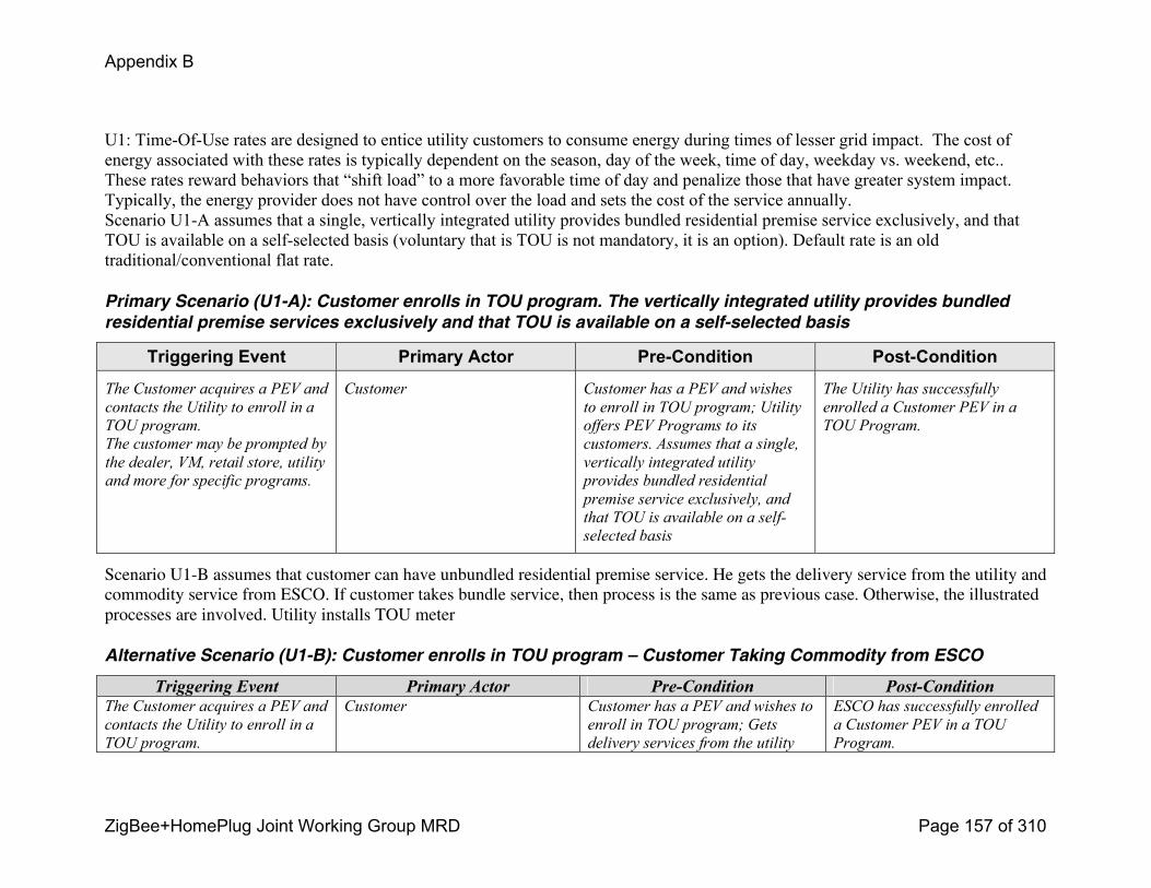
Appendix B
ZigBee+HomePlug Joint Working Group MRD Page 157 of 310
U1: TimeOfUse rates are designed to entice utility customers to consume energy during times of lesser grid impact. The cost of energy associated with these rates is typically dependent on the season, day of the week, time of day, weekday vs. weekend, etc.. These rates reward behaviors that “shift load” to a more favorable time of day and penalize those that have greater system impact. Typically, the energy provider does not have control over the load and sets the cost of the service annually.Scenario U1A assumes that a single, vertically integrated utility provides bundled residential premise service exclusively, and that TOU is available on a selfselected basis (voluntary that is TOU is not mandatory, it is an option). Default rate is an old traditional/conventional flat rate.
Primary Scenario (U1-A): Customer enrolls in TOU program. The vertically integrated utility provides bundled
residential premise services exclusively and that TOU is available on a self-selected basis
Triggering Event Primary Actor PreCondition PostCondition
The Customer acquires a PEV and
contacts the Utility to enroll in a
TOU program.
The customer may be prompted by
the dealer, VM, retail store, utility
and more for specific programs.
Customer Customer has a PEV and wishes
to enroll in TOU program; Utility
offers PEV Programs to its
customers. Assumes that a single,
vertically integrated utility
provides bundled residential
premise service exclusively, and
that TOU is available on a self
selected basis
The Utility has successfully
enrolled a Customer PEV in a
TOU Program.
Scenario U1-B assumes that customer can have unbundled residential premise service. He gets the delivery service from the utility and commodity service from ESCO. If customer takes bundle service, then process is the same as previous case. Otherwise, the illustrated processes are involved. Utility installs TOU meter
Alternative Scenario (U1-B): Customer enrolls in TOU program – Customer Taking Commodity from ESCO
Triggering Event Primary Actor PreCondition PostConditionThe Customer acquires a PEV and
contacts the Utility to enroll in a
TOU program.
Customer Customer has a PEV and wishes to
enroll in TOU program; Gets
delivery services from the utility
ESCO has successfully enrolled
a Customer PEV in a TOU
Program.
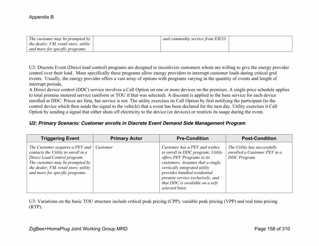
Appendix B
ZigBee+HomePlug Joint Working Group MRD Page 158 of 310
The customer may be prompted by
the dealer, VM, retail store, utility
and more for specific programs.
and commodity service from ESCO.
U2: Discrete Event (Direct load control) programs are designed to incentivize customers whom are willing to give the energy provider control over their load. More specifically these programs allow energy providers to interrupt customer loads during critical grid events. Usually, the energy provider offers a vast array of options with programs varying in the quantity of events and length of interrupt periods.A Direct device control (DDC) service involves a Call Option on one or more devices on the premises. A single price schedule applies to total premise metered service (uniform or TOU if that was selected). A discount is applied to the base service for each device enrolled in DDC. Prices are firm, but service is not. The utility exercises its Call Option by first notifying the participant (to the control device which then sends the signal to the vehicle) that a event has been declared for the nest day. Utility exercises it Call Option by sending a signal that either shuts off electricity to the device (or devices) or restricts its usage during the event.
U2: Primary Scenario: Customer enrolls in Discrete Event Demand Side Management Program
Triggering Event Primary Actor PreCondition PostCondition
The Customer acquires a PEV and
contacts the Utility to enroll in a
Direct Load Control program.
The customer may be prompted by
the dealer, VM, retail store, utility
and more for specific programs.
Customer Customer has a PEV and wishes
to enroll in DDC program; Utility
offers PEV Programs to its
customers. Assumes that a single,
vertically integrated utility
provides bundled residential
premise service exclusively, and
that DDC is available on a self
selected basis
The Utility has successfully
enrolled a Customer PEV in a
DDC Program.
U3: Variations on the basic TOU structure include critical peak pricing (CPP), variable peak pricing (VPP) and real time pricing (RTP).
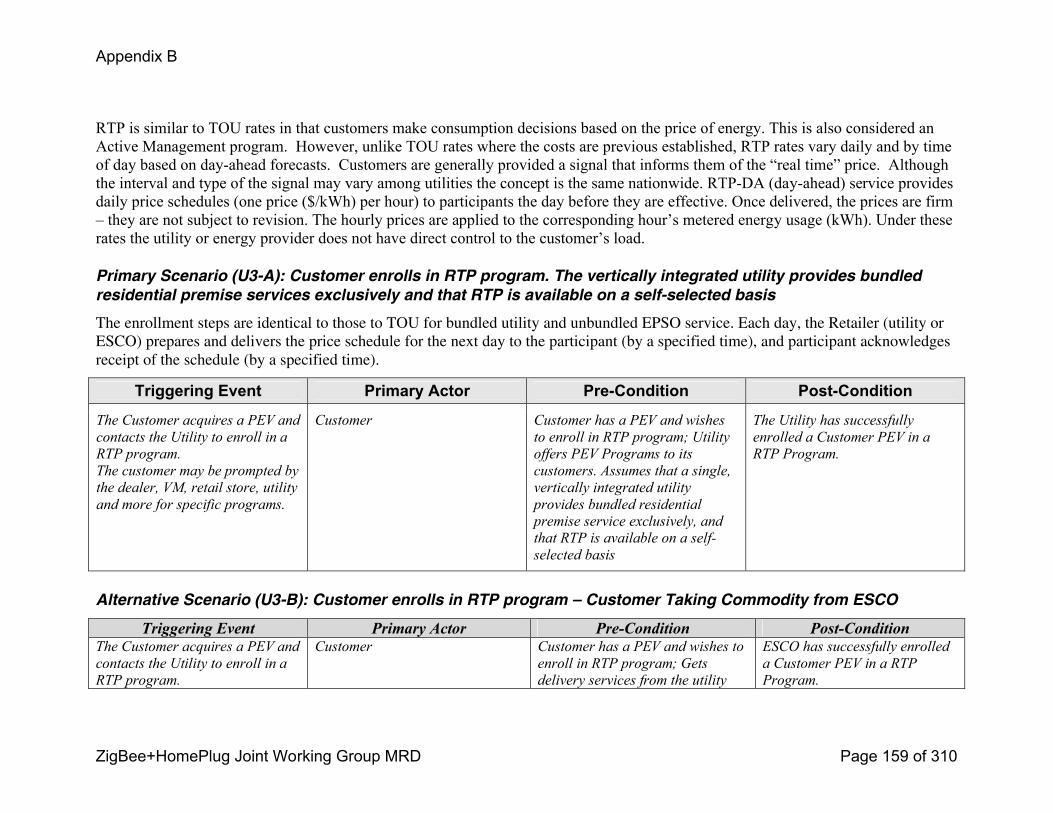
Appendix B
ZigBee+HomePlug Joint Working Group MRD Page 159 of 310
RTP is similar to TOU rates in that customers make consumption decisions based on the price of energy. This is also considered an Active Management program. However, unlike TOU rates where the costs are previous established, RTP rates vary daily and by time of day based on dayahead forecasts. Customers are generally provided a signal that informs them of the “real time” price. Although the interval and type of the signal may vary among utilities the concept is the same nationwide. RTPDA (dayahead) service provides daily price schedules (one price ($/kWh) per hour) to participants the day before they are effective. Once delivered, the prices are firm – they are not subject to revision. The hourly prices are applied to the corresponding hour’s metered energy usage (kWh). Under these rates the utility or energy provider does not have direct control to the customer’s load.
Primary Scenario (U3-A): Customer enrolls in RTP program. The vertically integrated utility provides bundled
residential premise services exclusively and that RTP is available on a self-selected basis
The enrollment steps are identical to those to TOU for bundled utility and unbundled EPSO service. Each day, the Retailer (utility or ESCO) prepares and delivers the price schedule for the next day to the participant (by a specified time), and participant acknowledges receipt of the schedule (by a specified time).
Triggering Event Primary Actor PreCondition PostCondition
The Customer acquires a PEV and
contacts the Utility to enroll in a
RTP program.
The customer may be prompted by
the dealer, VM, retail store, utility
and more for specific programs.
Customer Customer has a PEV and wishes
to enroll in RTP program; Utility
offers PEV Programs to its
customers. Assumes that a single,
vertically integrated utility
provides bundled residential
premise service exclusively, and
that RTP is available on a self
selected basis
The Utility has successfully
enrolled a Customer PEV in a
RTP Program.
Alternative Scenario (U3-B): Customer enrolls in RTP program – Customer Taking Commodity from ESCO
Triggering Event Primary Actor PreCondition PostConditionThe Customer acquires a PEV and
contacts the Utility to enroll in a
RTP program.
Customer Customer has a PEV and wishes to
enroll in RTP program; Gets
delivery services from the utility
ESCO has successfully enrolled
a Customer PEV in a RTP
Program.
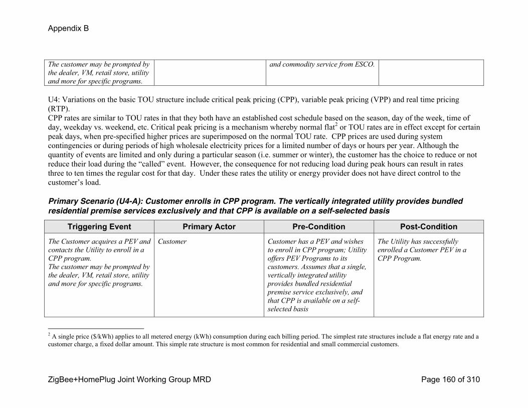
Appendix B
ZigBee+HomePlug Joint Working Group MRD Page 160 of 310
The customer may be prompted by
the dealer, VM, retail store, utility
and more for specific programs.
and commodity service from ESCO.
U4: Variations on the basic TOU structure include critical peak pricing (CPP), variable peak pricing (VPP) and real time pricing (RTP).CPP rates are similar to TOU rates in that they both have an established cost schedule based on the season, day of the week, time of day, weekday vs. weekend, etc. Critical peak pricing is a mechanism whereby normal flat2 or TOU rates are in effect except for certain peak days, when prespecified higher prices are superimposed on the normal TOU rate. CPP prices are used during system contingencies or during periods of high wholesale electricity prices for a limited number of days or hours per year. Although the quantity of events are limited and only during a particular season (i.e. summer or winter), the customer has the choice to reduce or not reduce their load during the “called” event. However, the consequence for not reducing load during peak hours can result in rates three to ten times the regular cost for that day. Under these rates the utility or energy provider does not have direct control to the customer’s load.
Primary Scenario (U4-A): Customer enrolls in CPP program. The vertically integrated utility provides bundled
residential premise services exclusively and that CPP is available on a self-selected basis
Triggering Event Primary Actor PreCondition PostCondition
The Customer acquires a PEV and
contacts the Utility to enroll in a
CPP program.
The customer may be prompted by
the dealer, VM, retail store, utility
and more for specific programs.
Customer Customer has a PEV and wishes
to enroll in CPP program; Utility
offers PEV Programs to its
customers. Assumes that a single,
vertically integrated utility
provides bundled residential
premise service exclusively, and
that CPP is available on a self
selected basis
The Utility has successfully
enrolled a Customer PEV in a
CPP Program.
2 A single price ($/kWh) applies to all metered energy (kWh) consumption during each billing period. The simplest rate structures include a flat energy rate and a customer charge, a fixed dollar amount. This simple rate structure is most common for residential and small commercial customers.
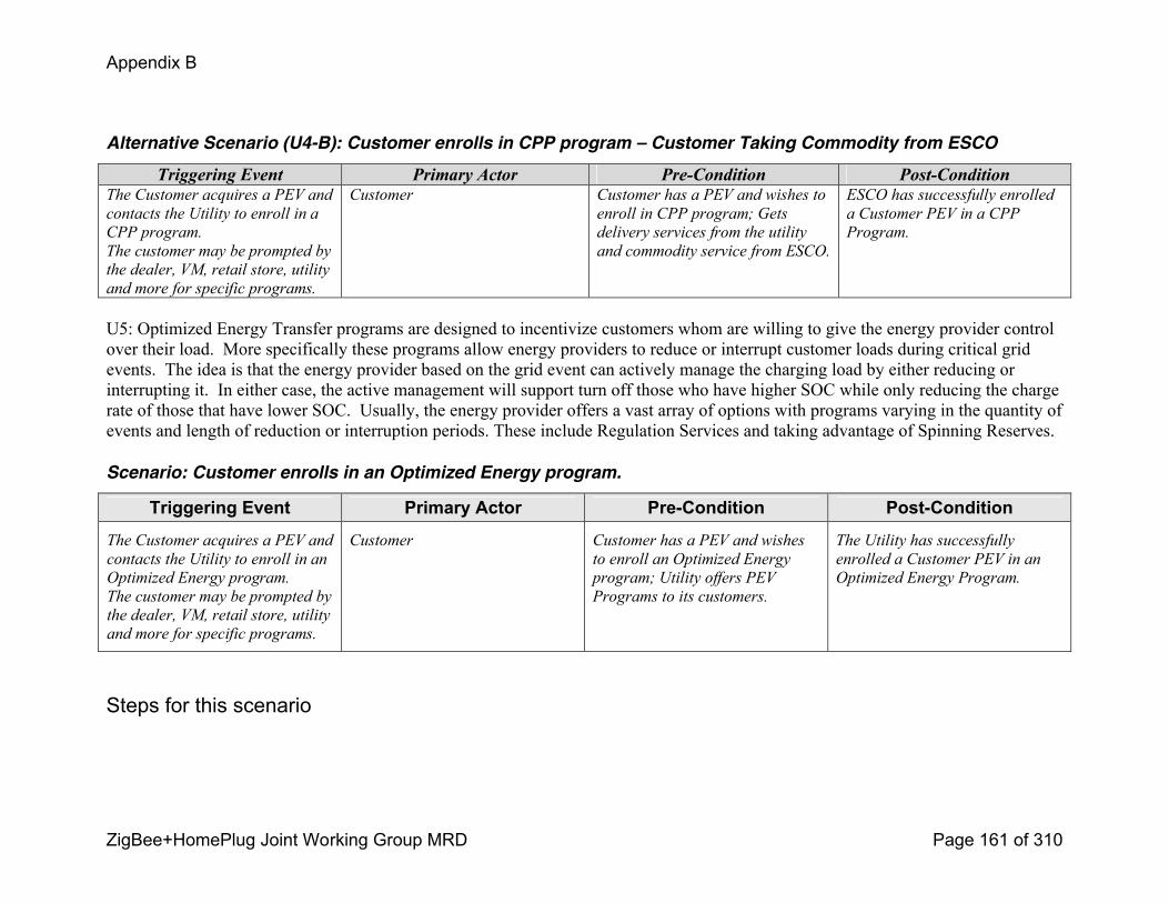
Appendix B
ZigBee+HomePlug Joint Working Group MRD Page 161 of 310
Alternative Scenario (U4-B): Customer enrolls in CPP program – Customer Taking Commodity from ESCO
Triggering Event Primary Actor PreCondition PostConditionThe Customer acquires a PEV and
contacts the Utility to enroll in a
CPP program.
The customer may be prompted by
the dealer, VM, retail store, utility
and more for specific programs.
Customer Customer has a PEV and wishes to
enroll in CPP program; Gets
delivery services from the utility
and commodity service from ESCO.
ESCO has successfully enrolled
a Customer PEV in a CPP
Program.
U5: Optimized Energy Transfer programs are designed to incentivize customers whom are willing to give the energy provider control over their load. More specifically these programs allow energy providers to reduce or interrupt customer loads during critical grid events. The idea is that the energy provider based on the grid event can actively manage the charging load by either reducing or interrupting it. In either case, the active management will support turn off those who have higher SOC while only reducing the charge rate of those that have lower SOC. Usually, the energy provider offers a vast array of options with programs varying in the quantity of events and length of reduction or interruption periods. These include Regulation Services and taking advantage of Spinning Reserves.
Scenario: Customer enrolls in an Optimized Energy program.
Triggering Event Primary Actor PreCondition PostCondition
The Customer acquires a PEV and
contacts the Utility to enroll in an
Optimized Energy program.
The customer may be prompted by
the dealer, VM, retail store, utility
and more for specific programs.
Customer Customer has a PEV and wishes
to enroll an Optimized Energy
program; Utility offers PEV
Programs to its customers.
The Utility has successfully
enrolled a Customer PEV in an
Optimized Energy Program.
Steps for this scenario
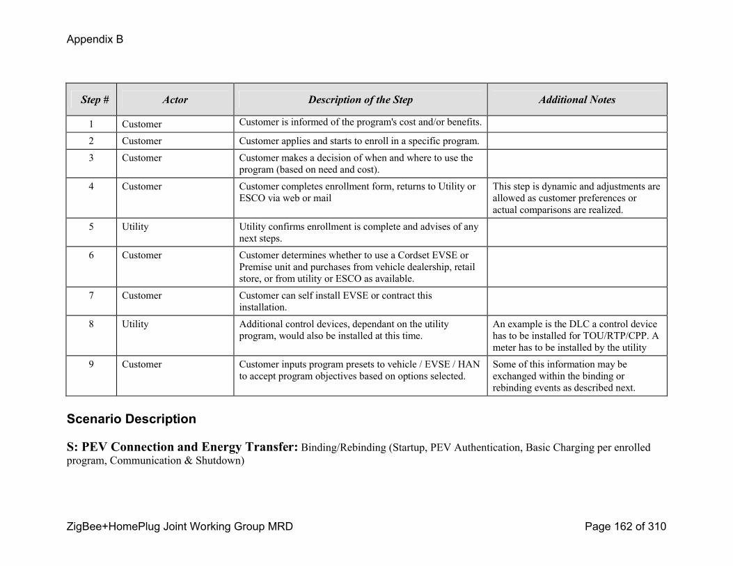
Appendix B
ZigBee+HomePlug Joint Working Group MRD Page 162 of 310
Step # Actor Description of the Step Additional Notes
1 Customer Customer is informed of the program's cost and/or benefits.
2 Customer Customer applies and starts to enroll in a specific program.
3 Customer Customer makes a decision of when and where to use the program (based on need and cost).
4 Customer Customer completes enrollment form, returns to Utility or ESCO via web or mail
This step is dynamic and adjustments are allowed as customer preferences or actual comparisons are realized.
5 Utility Utility confirms enrollment is complete and advises of any next steps.
6 Customer Customer determines whether to use a Cordset EVSE or Premise unit and purchases from vehicle dealership, retail store, or from utility or ESCO as available.
7 Customer Customer can self install EVSE or contract this installation.
8 Utility Additional control devices, dependant on the utility program, would also be installed at this time.
An example is the DLC a control device has to be installed for TOU/RTP/CPP. A meter has to be installed by the utility
9 Customer Customer inputs program presets to vehicle / EVSE / HAN to accept program objectives based on options selected.
Some of this information may be exchanged within the binding or rebinding events as described next.
Scenario Description
S: PEV Connection and Energy Transfer: Binding/Rebinding (Startup, PEV Authentication, Basic Charging per enrolled program, Communication & Shutdown)
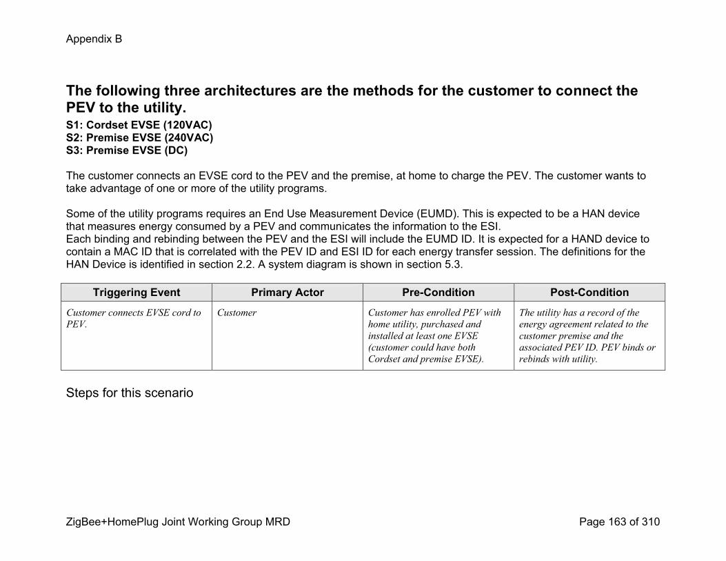
Appendix B
ZigBee+HomePlug Joint Working Group MRD Page 163 of 310
The following three architectures are the methods for the customer to connect the PEV to the utility. S1: Cordset EVSE (120VAC)S2: Premise EVSE (240VAC)S3: Premise EVSE (DC)
The customer connects an EVSE cord to the PEV and the premise, at home to charge the PEV. The customer wants to take advantage of one or more of the utility programs.
Some of the utility programs requires an End Use Measurement Device (EUMD). This is expected to be a HAN device that measures energy consumed by a PEV and communicates the information to the ESI.Each binding and rebinding between the PEV and the ESI will include the EUMD ID. It is expected for a HAND device to contain a MAC ID that is correlated with the PEV ID and ESI ID for each energy transfer session. The definitions for the HAN Device is identified in section 2.2. A system diagram is shown in section 5.3.
Triggering Event Primary Actor PreCondition PostCondition
Customer connects EVSE cord to
PEV.
Customer Customer has enrolled PEV with
home utility, purchased and
installed at least one EVSE
(customer could have both
Cordset and premise EVSE).
The utility has a record of the
energy agreement related to the
customer premise and the
associated PEV ID. PEV binds or
rebinds with utility.
Steps for this scenario

Appendix B
ZigBee+HomePlug Joint Working Group MRD Page 164 of 310
Step # Actor Description of the Step Additional Notes
1 Customer Customer connects EVSE cordset to Energy Portal at Premise, then to PEV if cordset is used. If premise EVSE is used, customer connects EVSE cord to PEV.
2 Customer Customer may observe that EVSE power is indicated and PEV indicator is activated that confirms charge will commence.
PEV and utility exchange/confirm PEV ID, energy request vs. available and details of specific utility program(s).
3 PEV/Utility Communication session is started and messages are sent and received by various actors.The PEV could send ID and message requests to the utility or intermediate devices.The Utility and other premise devices may simply send messages to the EVSE that would control the PEV energy needs by using the EVSE Pilot PWM.
Customer has the option to override any of these programs and receive energy at the available conditions.
4 Customer Customer returns to vehicle, observes charge is complete or interrupts cycle, then disconnects EVSE cord.
Scenario Description
L: Location variations: Connection location (PEV Authentication, Basic Charging per enrolled program)
The following four location variations are the alternatives for the customer to connect the PEV to the utility. L1: Home: Connects at premise
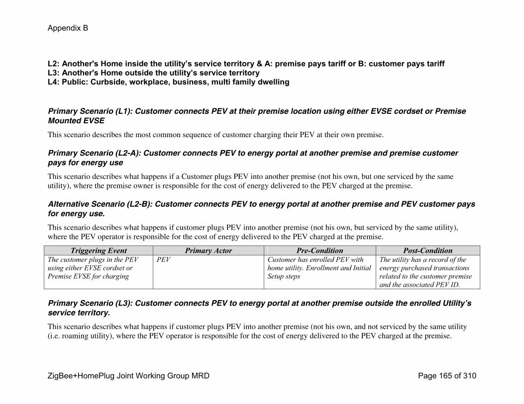
Appendix B
ZigBee+HomePlug Joint Working Group MRD Page 165 of 310
L2: Another's Home inside the utility’s service territory & A: premise pays tariff or B: customer pays tariffL3: Another's Home outside the utility’s service territoryL4: Public: Curbside, workplace, business, multi family dwelling
Primary Scenario (L1): Customer connects PEV at their premise location using either EVSE cordset or Premise
Mounted EVSE
This scenario describes the most common sequence of customer charging their PEV at their own premise.
Primary Scenario (L2-A): Customer connects PEV to energy portal at another premise and premise customer
pays for energy use
This scenario describes what happens if a Customer plugs PEV into another premise (not his own, but one serviced by the same utility), where the premise owner is responsible for the cost of energy delivered to the PEV charged at the premise.
Alternative Scenario (L2-B): Customer connects PEV to energy portal at another premise and PEV customer pays
for energy use.
This scenario describes what happens if customer plugs PEV into another premise (not his own, but serviced by the same utility), where the PEV operator is responsible for the cost of energy delivered to the PEV charged at the premise.
Triggering Event Primary Actor PreCondition PostConditionThe customer plugs in the PEV
using either EVSE cordset or
Premise EVSE for charging
PEV Customer has enrolled PEV with
home utility. Enrollment and Initial
Setup steps
The utility has a record of the
energy purchased transactions
related to the customer premise
and the associated PEV ID.
Primary Scenario (L3): Customer connects PEV to energy portal at another premise outside the enrolled Utility’s
service territory.
This scenario describes what happens if customer plugs PEV into another premise (not his own, and not serviced by the same utility (i.e. roaming utility), where the PEV operator is responsible for the cost of energy delivered to the PEV charged at the premise.
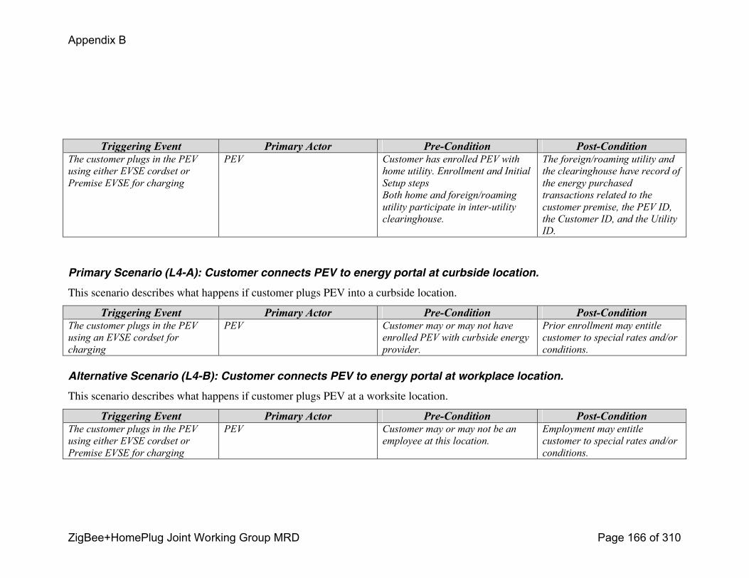
Appendix B
ZigBee+HomePlug Joint Working Group MRD Page 166 of 310
Triggering Event Primary Actor PreCondition PostConditionThe customer plugs in the PEV
using either EVSE cordset or
Premise EVSE for charging
PEV Customer has enrolled PEV with
home utility. Enrollment and Initial
Setup steps
Both home and foreign/roaming
utility participate in interutility
clearinghouse.
The foreign/roaming utility and
the clearinghouse have record of
the energy purchased
transactions related to the
customer premise, the PEV ID,
the Customer ID, and the Utility
ID.
Primary Scenario (L4-A): Customer connects PEV to energy portal at curbside location.
This scenario describes what happens if customer plugs PEV into a curbside location.
Triggering Event Primary Actor PreCondition PostConditionThe customer plugs in the PEV
using an EVSE cordset for
charging
PEV Customer may or may not have
enrolled PEV with curbside energy
provider.
Prior enrollment may entitle
customer to special rates and/or
conditions.
Alternative Scenario (L4-B): Customer connects PEV to energy portal at workplace location.
This scenario describes what happens if customer plugs PEV at a worksite location.
Triggering Event Primary Actor PreCondition PostConditionThe customer plugs in the PEV
using either EVSE cordset or
Premise EVSE for charging
PEV Customer may or may not be an
employee at this location.
Employment may entitle
customer to special rates and/or
conditions.
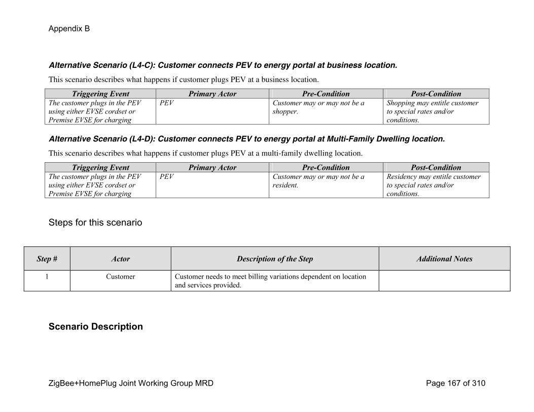
Appendix B
ZigBee+HomePlug Joint Working Group MRD Page 167 of 310
Alternative Scenario (L4-C): Customer connects PEV to energy portal at business location.
This scenario describes what happens if customer plugs PEV at a business location.
Triggering Event Primary Actor PreCondition PostConditionThe customer plugs in the PEV
using either EVSE cordset or
Premise EVSE for charging
PEV Customer may or may not be a
shopper.
Shopping may entitle customer
to special rates and/or
conditions.
Alternative Scenario (L4-D): Customer connects PEV to energy portal at Multi-Family Dwelling location.
This scenario describes what happens if customer plugs PEV at a multi-family dwelling location.
Triggering Event Primary Actor PreCondition PostConditionThe customer plugs in the PEV
using either EVSE cordset or
Premise EVSE for charging
PEV Customer may or may not be a
resident.
Residency may entitle customer
to special rates and/or
conditions.
Steps for this scenario
Step # Actor Description of the Step Additional Notes
1 Customer Customer needs to meet billing variations dependent on location and services provided.
Scenario Description
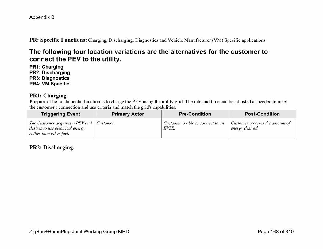
Appendix B
ZigBee+HomePlug Joint Working Group MRD Page 168 of 310
PR: Specific Functions: Charging, Discharging, Diagnostics and Vehicle Manufacturer (VM) Specific applications.
The following four location variations are the alternatives for the customer to connect the PEV to the utility. PR1: ChargingPR2: DischargingPR3: DiagnosticsPR4: VM Specific
PR1: Charging.Purpose: The fundamental function is to charge the PEV using the utility grid. The rate and time can be adjusted as needed to meet the customer's connection and use criteria and match the grid's capabilities.
Triggering Event Primary Actor PreCondition PostCondition
The Customer acquires a PEV and
desires to use electrical energy
rather than other fuel.
Customer Customer is able to connect to an
EVSE.
Customer receives the amount of
energy desired.
PR2: Discharging.

Appendix B
ZigBee+HomePlug Joint Working Group MRD Page 169 of 310
Purpose: An alternative function of the PEV is to discharge the RESS. The customer can take advantage of rate or opportunity aspects by using this feature.
Discharges fall into the following four categories:
D1: Vehicle to Grid (V2G). This allows the customer the option of returning power to the grid. This may have an advantage to the grid if it is operating at peak loads.
D2: Vehicle to Home (V2H). This allows the customer the option of powering a home in the event of a grid outage. This function would have to include the same safety features as a Home Generator.
D3: Vehicle to Load (V2L). This allows the customer the option of powering devices that are not connected to the grid. This could be portable power at a construction site or Islanding where the vehicle may be providing power to a variety of devices.
D4: Vehicle to Vehicle (V2V). This has a couple of aspects such as jumpstarting another vehicle or providing power in parallel with other vehicles for a higher power level of Islanding.
Triggering Event Primary Actor PreCondition PostCondition
The Customer acquires a PEV and
desires to use electrical energy as
a source for offboard power.
Customer Customer is able to connect to an
EVSE.
Customer delivers the amount of
energy desired.
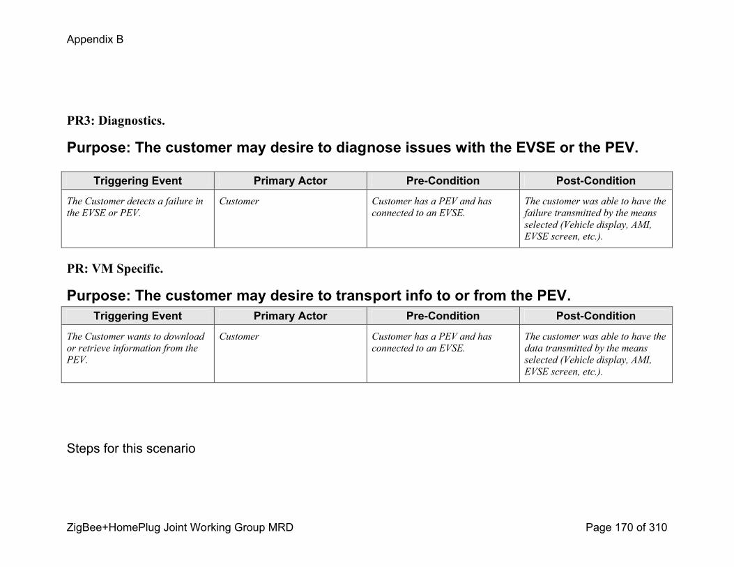
Appendix B
ZigBee+HomePlug Joint Working Group MRD Page 170 of 310
PR3: Diagnostics.
Purpose: The customer may desire to diagnose issues with the EVSE or the PEV.
Triggering Event Primary Actor PreCondition PostCondition
The Customer detects a failure in
the EVSE or PEV.
Customer Customer has a PEV and has
connected to an EVSE.
The customer was able to have the
failure transmitted by the means
selected (Vehicle display, AMI,
EVSE screen, etc.).
PR: VM Specific.
Purpose: The customer may desire to transport info to or from the PEV.Triggering Event Primary Actor PreCondition PostCondition
The Customer wants to download
or retrieve information from the
PEV.
Customer Customer has a PEV and has
connected to an EVSE.
The customer was able to have the
data transmitted by the means
selected (Vehicle display, AMI,
EVSE screen, etc.).
Steps for this scenario
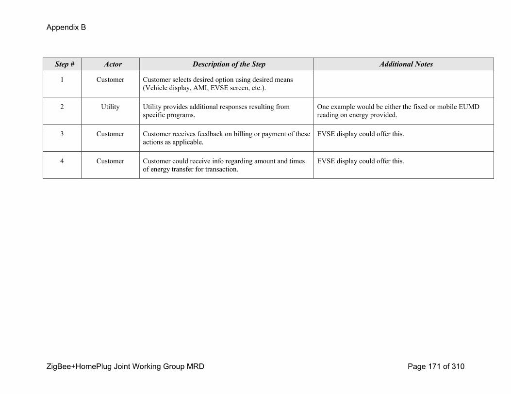
Appendix B
ZigBee+HomePlug Joint Working Group MRD Page 171 of 310
Step # Actor Description of the Step Additional Notes
1 Customer Customer selects desired option using desired means (Vehicle display, AMI, EVSE screen, etc.).
2 Utility Utility provides additional responses resulting from specific programs.
One example would be either the fixed or mobile EUMD reading on energy provided.
3 Customer Customer receives feedback on billing or payment of these actions as applicable.
EVSE display could offer this.
4 Customer Customer could receive info regarding amount and times of energy transfer for transaction.
EVSE display could offer this.
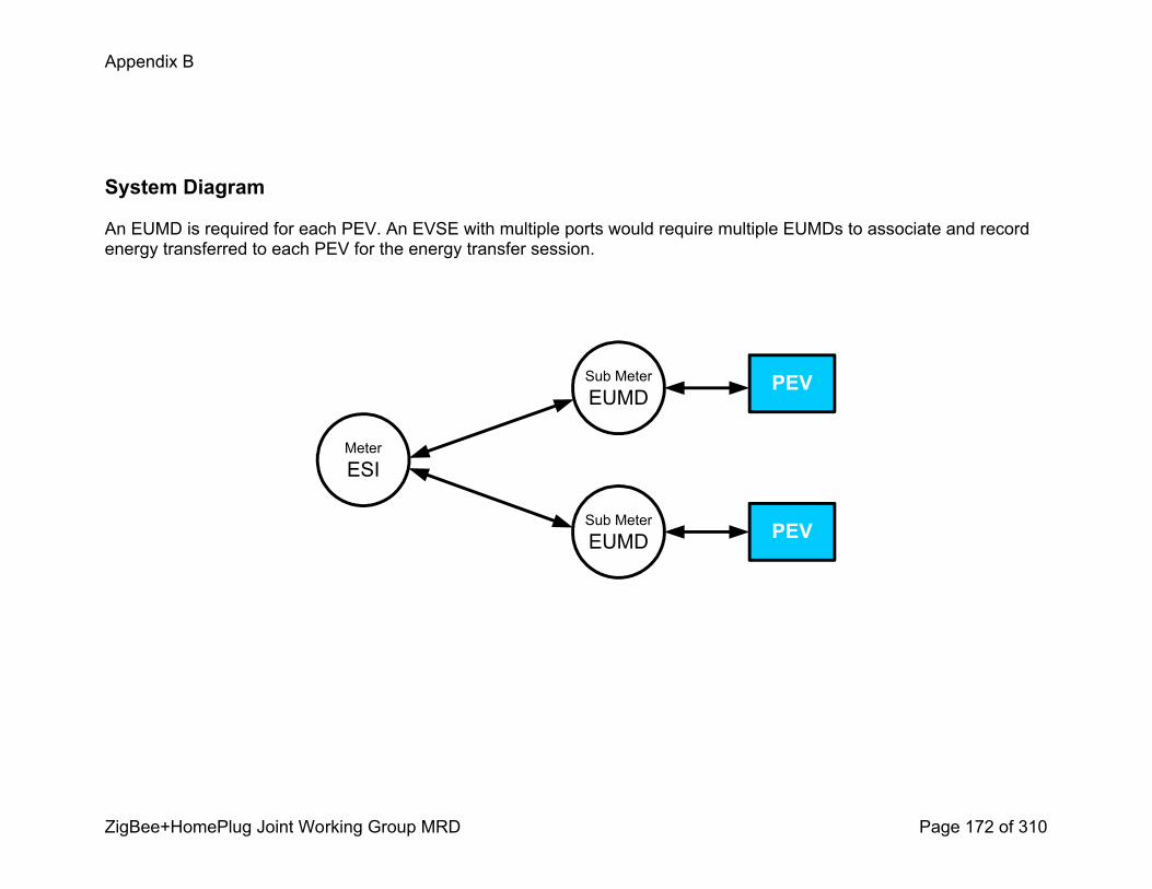
Appendix B
ZigBee+HomePlug Joint Working Group MRD Page 172 of 310
System Diagram
An EUMD is required for each PEV. An EVSE with multiple ports would require multiple EUMDs to associate and record energy transferred to each PEV for the energy transfer session.
MeterESI
Sub MeterEUMD
Sub MeterEUMD
PEV
PEV
Appendix B
ZigBee+HomePlug Joint Working Group MRD Page 173 of 310
b. PEV Use Case 1 Utility provides services to Plugin Electric Vehicle (PEV) Customer
0.23 Use Case TitleUtility provides services to Plugin Electric Vehicle (PEV) Customer
0.24 Use Case SummaryCustomers are interested in fueling vehicles with electricity. Electric Vehicles (EV) and Plugin Electric Vehicles (PEV) are emerging transportation options for consumers. Electric utilities desire to support these emerging loads with electricity at “off peak” times when energy costs are low and generation and power delivery assets are underutilized. PEV manufacturers are interested in working with utilities to develop customer rates/programs which could provide consumers with an increased incentive to purchase a PEV. To enable utility customer rates/programs specifically to customers with PEVs, the utility must offer special services for these customers. These services include the ability to enroll, register, and initially setup communications between a PEV and the utility (onetime setup), the ability to repeatedly reestablish communications for each PEV charging session (repeat communications/rebinding), the ability to provide PEV charging (and other) status information to customer information channels (e.g. web, display devices), and the ability to correctly bill PEV customers according to their selected rates/programs.
0.25 Use Case Detailed Narrative
Within a utility service territory, the consumer can plug in a PEV to receive a charge of electrical energy at their premise or plug in at another premise location. The Utility may offer the Customer a PEV tariff that provides a low rate for offpeak charging and a higher rate for onpeak charging. The utility must provide services to support energy supplied to customer PEV. These services include enrollment into a PEV program, PEV communications session binding, PEV energy billing, and PEV information services. The utility will implement an enrollment system for Customers with a PEV including registration and commissioning. The utility’s Energy Services Communication Interface (ESCI) shall allow for the establishment of a communications session (communications binding), at a premise location each time a PEV plugs in for charging. Energy supplied to the PEV is reported to the utility for billing and presentation to the Customer. Information related to utility PEV programs, energy usage, and PEV charging status/information will be made available to the Customer for viewing via a website or other customer provided display equipment.
This use case covers three scenarios:
Appendix B
ZigBee+HomePlug Joint Working Group MRD Page 174 of 310
1) Customer enrolls in PEV program and completes initial setup for PEV – Utilities communications. The following programs are discussed
! U1: Enrollment Process to Time of Use (TOU) Program
! U2: Enrollment Process to Direct Load/Device Control (DDC) Program
! U3: Enrollment Process to Real Time Pricing (RTP) or Hourly/Periodic Pricing Program
! U4: Enrollment Process to Critical Peak Pricing (CPP) or Hourly/Periodic Pricing Program
! U5: Enrollment Process to Active Load Management Program
2) PEV and Utility establish/reestablish communications session at the time of charging
3) Utility provides billing services for PEV charging to Customer
4) Utility provides Customer access to PEV charging and status information
0.26 Business Rules and Assumptions! PEV Customer has an account with utility and electrical service at a premise served by the utility.
! PEV and utility may have communications capabilities, enabled by utility provided Energy Services Communication Interface (ESCI).
! The customer awareness of the utility and vehicle programs is prompted by both the utility providers and the vehicle manufacturers.
! The utility offers PEV programs and services for its customers and will provide the necessary support processes for enrollment, communications, and billing
! The Vehicle manufacturers would provide information to the customer about fuel and/or emission gains of the vehicles offered and promote the utility and convenience of connecting to the grid
Appendix B
ZigBee+HomePlug Joint Working Group MRD Page 175 of 310
! Utility shall maintain information on all Customers and PEVs enrolled in the PEV programs, including demand side management programs, associated PEV IDs, customer IDs, and premise IDs.
! In the absence or failure of PEV-utility communications, or if PEV ID validation fails, PEV charging will always proceed; however, without the incentive rates and with all energy charges accruing to the premise customer according to the premise customer’s default rate/service plan.
! The actual PEV charging processes, including scenarios for intra- and inter- utility roaming, are covered in use case P2.
! End Use Measurement Device (EUMD), either fixed or mobile, is always available for energy validation of PEV charging. If not available, charging will proceed, but with limitations on incentive rates and with all energy charges accruing to the premise customer. This may or may not prevent certain charging status indicators / metrics being available to customer for presentation/display purposes.
! EUMD function can be inclusively located anywhere in a zone from the PEV and the branch circuit panel connection.
! To allow for possibility of the EUMD being a part of/within the PEV, PEV is a sub-meter to the primary utility billing meter at any premise (as opposed to being a separate service account with dual meter socket adapter)
! The PEV & Utility will communicate to implement one or more the previously described Utility programs (see section 3.2)
ActorsDescribe the primary and secondary actors involved in the use case. This might include all the people (their job), systems, databases,
organizations, and devices involved in or affected by the Function (e.g. operators, system administrators, customer, end users, service
personnel, executives, meter, realtime database, ISO, power system). Actors listed for this use case should be copied from the global
actors list to ensure consistency across all use cases.
Actor Name Actor Type (person, device, system etc.)
Actor Description
AES – See ESCO Organization Alternative Energy SupplierCharger Device The charger can either be onboard the vehicle or offboard. Onboard chargers require AC energy transfer to
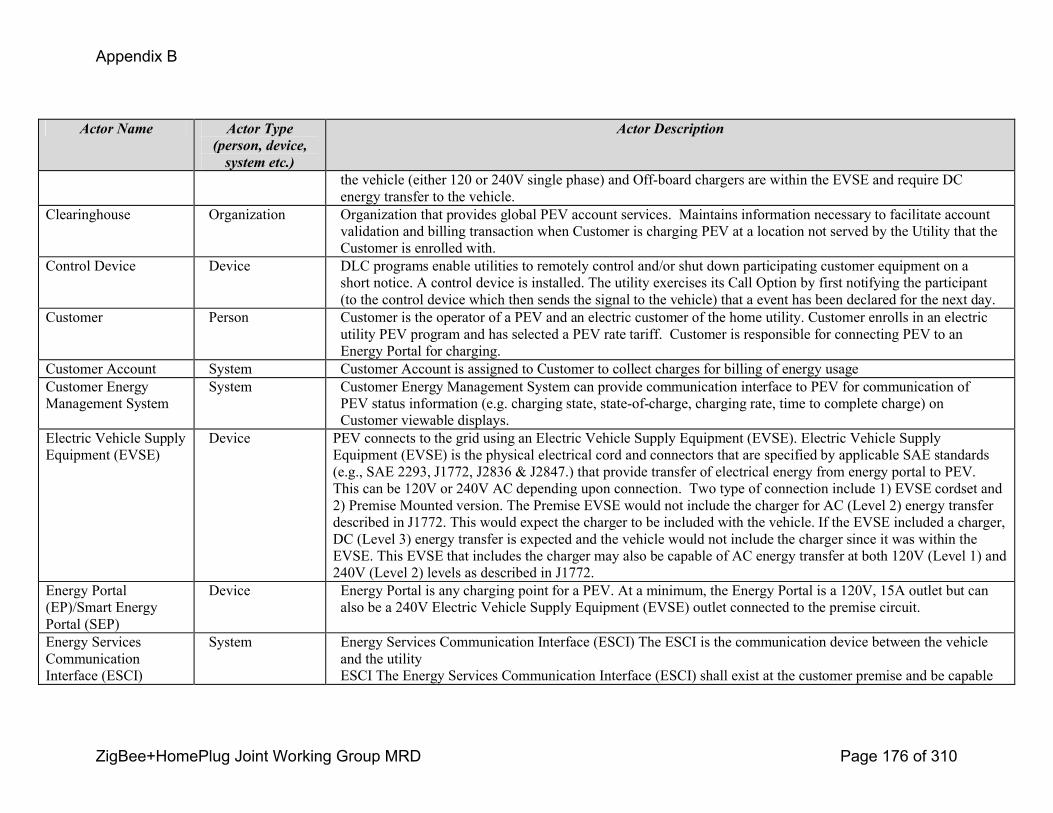
Appendix B
ZigBee+HomePlug Joint Working Group MRD Page 176 of 310
Actor Name Actor Type (person, device, system etc.)
Actor Description
the vehicle (either 120 or 240V single phase) and Offboard chargers are within the EVSE and require DC energy transfer to the vehicle.
Clearinghouse Organization Organization that provides global PEV account services. Maintains information necessary to facilitate account validation and billing transaction when Customer is charging PEV at a location not served by the Utility that the Customer is enrolled with.
Control Device Device DLC programs enable utilities to remotely control and/or shut down participating customer equipment on a short notice. A control device is installed. The utility exercises its Call Option by first notifying the participant (to the control device which then sends the signal to the vehicle) that a event has been declared for the next day.
Customer Person Customer is the operator of a PEV and an electric customer of the home utility. Customer enrolls in an electric utility PEV program and has selected a PEV rate tariff. Customer is responsible for connecting PEV to an Energy Portal for charging.
Customer Account System Customer Account is assigned to Customer to collect charges for billing of energy usageCustomer Energy Management System
System Customer Energy Management System can provide communication interface to PEV for communication of PEV status information (e.g. charging state, stateofcharge, charging rate, time to complete charge) on Customer viewable displays.
Electric Vehicle Supply Equipment (EVSE)
Device PEV connects to the grid using an Electric Vehicle Supply Equipment (EVSE). Electric Vehicle Supply Equipment (EVSE) is the physical electrical cord and connectors that are specified by applicable SAE standards (e.g., SAE 2293, J1772, J2836 & J2847.) that provide transfer of electrical energy from energy portal to PEV. This can be 120V or 240V AC depending upon connection. Two type of connection include 1) EVSE cordset and 2) Premise Mounted version. The Premise EVSE would not include the charger for AC (Level 2) energy transfer described in J1772. This would expect the charger to be included with the vehicle. If the EVSE included a charger, DC (Level 3) energy transfer is expected and the vehicle would not include the charger since it was within the EVSE. This EVSE that includes the charger may also be capable of AC energy transfer at both 120V (Level 1) and 240V (Level 2) levels as described in J1772.
Energy Portal (EP)/Smart Energy Portal (SEP)
Device Energy Portal is any charging point for a PEV. At a minimum, the Energy Portal is a 120V, 15A outlet but can also be a 240V Electric Vehicle Supply Equipment (EVSE) outlet connected to the premise circuit.
Energy Services Communication Interface (ESCI)
System Energy Services Communication Interface (ESCI) The ESCI is the communication device between the vehicle and the utilityESCI The Energy Services Communication Interface (ESCI) shall exist at the customer premise and be capable
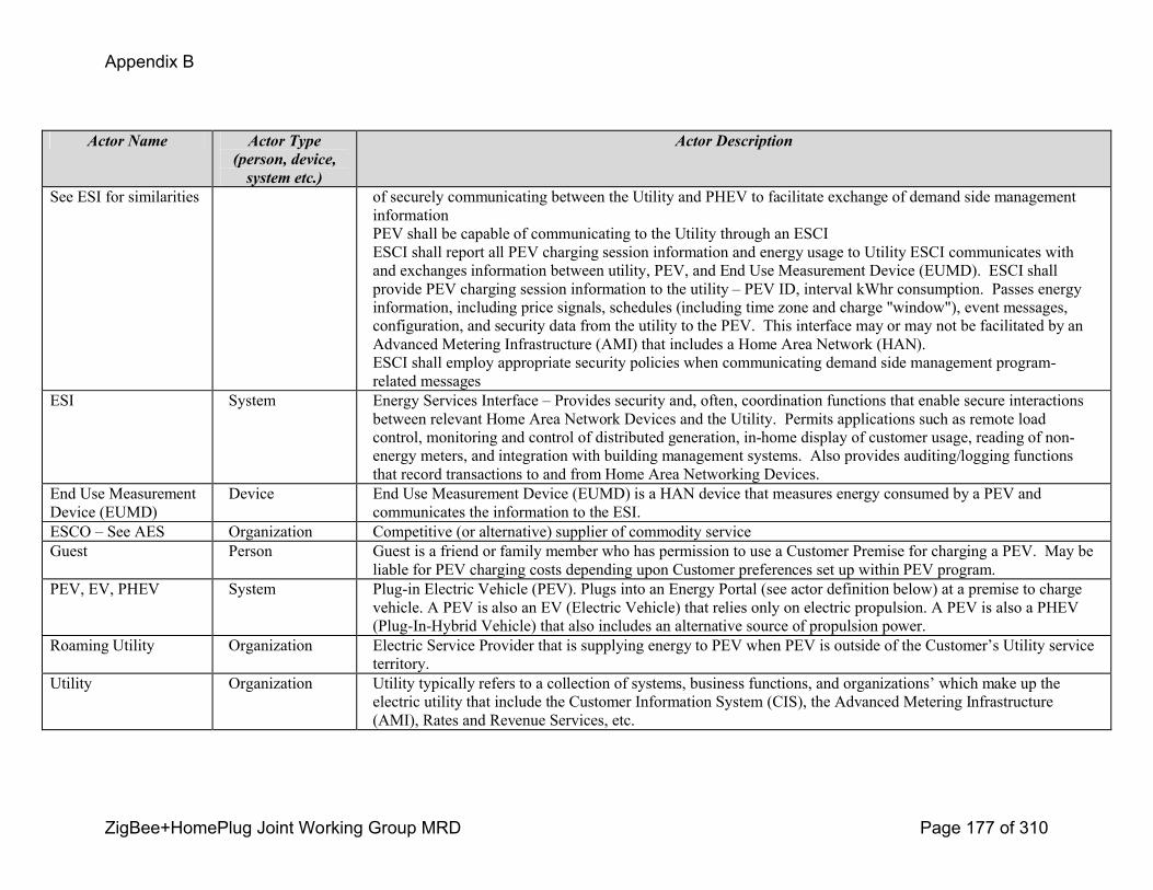
Appendix B
ZigBee+HomePlug Joint Working Group MRD Page 177 of 310
Actor Name Actor Type (person, device, system etc.)
Actor Description
See ESI for similarities of securely communicating between the Utility and PHEV to facilitate exchange of demand side management informationPEV shall be capable of communicating to the Utility through an ESCIESCI shall report all PEV charging session information and energy usage to Utility ESCI communicates with and exchanges information between utility, PEV, and End Use Measurement Device (EUMD). ESCI shall provide PEV charging session information to the utility – PEV ID, interval kWhr consumption. Passes energy information, including price signals, schedules (including time zone and charge "window"), event messages, configuration, and security data from the utility to the PEV. This interface may or may not be facilitated by an Advanced Metering Infrastructure (AMI) that includes a Home Area Network (HAN). ESCI shall employ appropriate security policies when communicating demand side management programrelated messages
ESI System Energy Services Interface – Provides security and, often, coordination functions that enable secure interactions between relevant Home Area Network Devices and the Utility. Permits applications such as remote load control, monitoring and control of distributed generation, inhome display of customer usage, reading of nonenergy meters, and integration with building management systems. Also provides auditing/logging functions that record transactions to and from Home Area Networking Devices.
End Use Measurement Device (EUMD)
Device End Use Measurement Device (EUMD) is a HAN device that measures energy consumed by a PEV and communicates the information to the ESI.
ESCO – See AES Organization Competitive (or alternative) supplier of commodity serviceGuest Person Guest is a friend or family member who has permission to use a Customer Premise for charging a PEV. May be
liable for PEV charging costs depending upon Customer preferences set up within PEV program.PEV, EV, PHEV System Plugin Electric Vehicle (PEV). Plugs into an Energy Portal (see actor definition below) at a premise to charge
vehicle. A PEV is also an EV (Electric Vehicle) that relies only on electric propulsion. A PEV is also a PHEV (PlugInHybrid Vehicle) that also includes an alternative source of propulsion power.
Roaming Utility Organization Electric Service Provider that is supplying energy to PEV when PEV is outside of the Customer’s Utility service territory.
Utility Organization Utility typically refers to a collection of systems, business functions, and organizations’ which make up the electric utility that include the Customer Information System (CIS), the Advanced Metering Infrastructure (AMI), Rates and Revenue Services, etc.
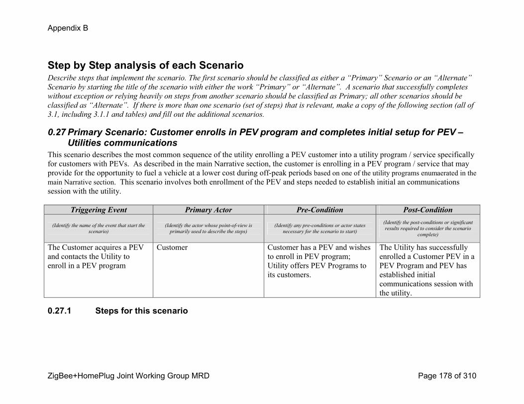
Appendix B
ZigBee+HomePlug Joint Working Group MRD Page 178 of 310
Step by Step analysis of each ScenarioDescribe steps that implement the scenario. The first scenario should be classified as either a “Primary” Scenario or an “Alternate”
Scenario by starting the title of the scenario with either the work “Primary” or “Alternate”. A scenario that successfully completes
without exception or relying heavily on steps from another scenario should be classified as Primary; all other scenarios should be
classified as “Alternate”. If there is more than one scenario (set of steps) that is relevant, make a copy of the following section (all of
3.1, including 3.1.1 and tables) and fill out the additional scenarios.
0.27 Primary Scenario: Customer enrolls in PEV program and completes initial setup for PEV –Utilities communications
This scenario describes the most common sequence of the utility enrolling a PEV customer into a utility program / service specifically for customers with PEVs. As described in the main Narrative section, the customer is enrolling in a PEV program / service that may provide for the opportunity to fuel a vehicle at a lower cost during offpeak periods based on one of the utility programs enumaerated in the main Narrative section. This scenario involves both enrollment of the PEV and steps needed to establish initial an communications session with the utility.
Triggering Event Primary Actor PreCondition PostCondition
(Identify the name of the event that start the
scenario)
(Identify the actor whose pointofview is
primarily used to describe the steps)
(Identify any preconditions or actor states
necessary for the scenario to start)
(Identify the postconditions or significant
results required to consider the scenario
complete)
The Customer acquires a PEV and contacts the Utility to enroll in a PEV program
Customer Customer has a PEV and wishes to enroll in PEV program; Utility offers PEV Programs to its customers.
The Utility has successfully enrolled a Customer PEV in a PEV Program and PEV has established initial communications session with the utility.
0.27.1 Steps for this scenario

Appendix B
ZigBee+HomePlug Joint Working Group MRD Page 179 of 310
Step # Actor Description of the Step Additional Notes
# What actor, either primary or
secondary is responsible for the
activity in this step?
Describe the actions that take place in this step. The step should be described in
active, present tense.
Elaborate on any additional description or value
of the step to help support the descriptions. Short
notes on architecture challenges, etc. may also be
noted in this column..
1 Customer Customer initiates request to enroll PEV in a PEV Program by contacting Utility and provides Customer and PEV information (i.e. Customer Account information, PEV ID, etc.).
Customer uses phone, Internet, or other communications channel.
Preference for PEV is PEV VIN #
2 Utility Utility authenticates Customer, Customer account, and Premise information, and collects PEV information including PEV ID.
3 Utility Utility presents Customer with PEV Program information and PEV Program selections.
4 Customer Customer selects PEV Program and Service Plan, sets PEV program parameters (i.e. guest charging, allow roaming, etc.). The Customer and PEV are now enrolled in a utility PEV program.
5 Customer Customer connects PEV to Energy Portal at their premise location.
6 PEV PEV senses power to onboard charging unit and activates ‘On Plug’ state.
7 PEV/ Energy Services Communications Interface (ESCI)
PEV and Energy Services Communications Interface (ESCI) initiate a secure communications session.
Implementation could have PEV or ESCI as initiator of session.
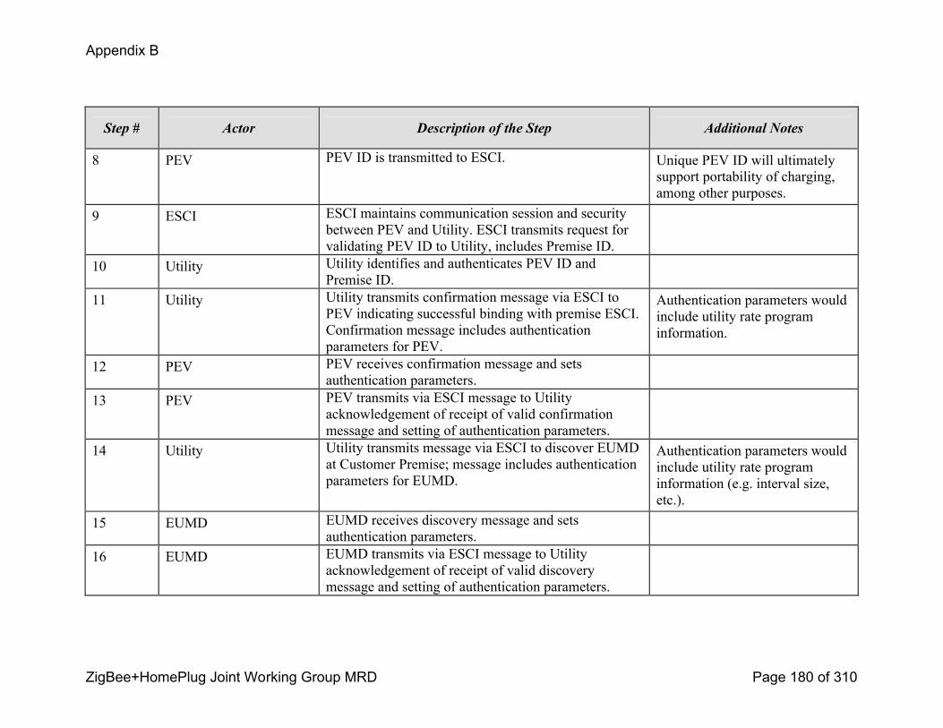
Appendix B
ZigBee+HomePlug Joint Working Group MRD Page 180 of 310
Step # Actor Description of the Step Additional Notes
8 PEV PEV ID is transmitted to ESCI. Unique PEV ID will ultimately support portability of charging, among other purposes.
9 ESCI ESCI maintains communication session and security between PEV and Utility. ESCI transmits request for validating PEV ID to Utility, includes Premise ID.
10 Utility Utility identifies and authenticates PEV ID and Premise ID.
11 Utility Utility transmits confirmation message via ESCI to PEV indicating successful binding with premise ESCI. Confirmation message includes authentication parameters for PEV.
Authentication parameters would include utility rate program information.
12 PEV PEV receives confirmation message and sets authentication parameters.
13 PEV PEV transmits via ESCI message to Utility acknowledgement of receipt of valid confirmation message and setting of authentication parameters.
14 Utility Utility transmits message via ESCI to discover EUMD at Customer Premise; message includes authentication parameters for EUMD.
Authentication parameters would include utility rate program information (e.g. interval size, etc.).
15 EUMD EUMD receives discovery message and sets authentication parameters.
16 EUMD EUMD transmits via ESCI message to Utility acknowledgement of receipt of valid discovery message and setting of authentication parameters.
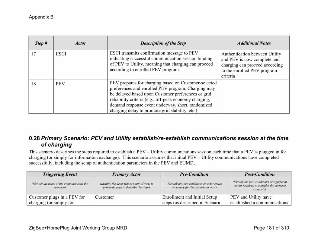
Appendix B
ZigBee+HomePlug Joint Working Group MRD Page 181 of 310
Step # Actor Description of the Step Additional Notes
17 ESCI ESCI transmits confirmation message to PEV indicating successful communication session binding of PEV to Utility, meaning that charging can proceed according to enrolled PEV program.
Authentication between Utility and PEV is now complete and charging can proceed according to the enrolled PEV program criteria
18 PEV PEV prepares for charging based on Customerselected preferences and enrolled PEV program. Charging may be delayed based upon Customer preferences or grid reliability criteria (e.g., offpeak economy charging, demand response event underway, short, randomized charging delay to promote grid stability, etc.)
0.28Primary Scenario: PEV and Utility establish/reestablish communications session at the time of charging
This scenario describes the steps required to establish a PEV – Utility communications session each time that a PEV is plugged in for charging (or simply for information exchange). This scenario assumes that initial PEV – Utility communications have completed successfully, including the setup of authentication parameters in the PEV and EUMD,
Triggering Event Primary Actor PreCondition PostCondition
(Identify the name of the event that start the
scenario)
(Identify the actor whose pointofview is
primarily used to describe the steps)
(Identify any preconditions or actor states
necessary for the scenario to start)
(Identify the postconditions or significant
results required to consider the scenario
complete)
Customer plugs in a PEV for charging (or simply for
Customer Enrollment and Initial Setup steps (as described in Scenario
PEV and Utility have established a communications
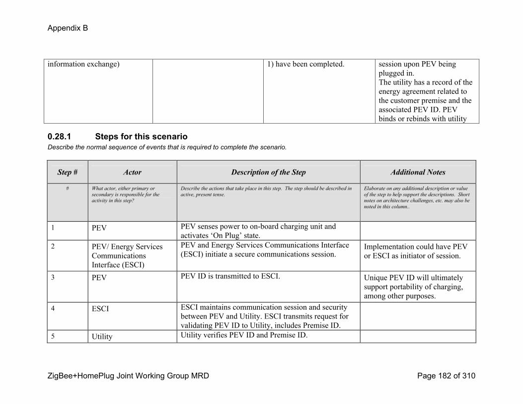
Appendix B
ZigBee+HomePlug Joint Working Group MRD Page 182 of 310
information exchange) 1) have been completed. session upon PEV being plugged in.The utility has a record of the energy agreement related to the customer premise and the associated PEV ID. PEV binds or rebinds with utility
0.28.1 Steps for this scenarioDescribe the normal sequence of events that is required to complete the scenario.
Step # Actor Description of the Step Additional Notes
# What actor, either primary or
secondary is responsible for the
activity in this step?
Describe the actions that take place in this step. The step should be described in
active, present tense.
Elaborate on any additional description or value
of the step to help support the descriptions. Short
notes on architecture challenges, etc. may also be
noted in this column..
1 PEV PEV senses power to onboard charging unit and activates ‘On Plug’ state.
2 PEV/ Energy Services Communications Interface (ESCI)
PEV and Energy Services Communications Interface (ESCI) initiate a secure communications session.
Implementation could have PEV or ESCI as initiator of session.
3 PEV PEV ID is transmitted to ESCI. Unique PEV ID will ultimately support portability of charging, among other purposes.
4 ESCI ESCI maintains communication session and security between PEV and Utility. ESCI transmits request for validating PEV ID to Utility, includes Premise ID.
5 Utility Utility verifies PEV ID and Premise ID.

Appendix B
ZigBee+HomePlug Joint Working Group MRD Page 183 of 310
Step # Actor Description of the Step Additional Notes
6 Utility Utility transmits confirmation message via ESCI to End Use Measurement Device (EUMD) indicating successful binding with premise ESCI.
7 ESCI ESCI transmits confirmation message to PEV indicating successful communication session binding of PEV to Utility, meaning that charging can proceed according to enrolled PEV program.
8 PEV PEV sends Energy Request (amount and rate) and Schedule (according to enrolled PEV program)
9 Utility Utility compares request with available and confirms or adjusts for message back to PEV Utility sends Energy Available (amount and rate) and Schedule (according to enrolled PEV program)
10 PEV PEV prepares for charging
11 PEV PEV begins charging based on Customerselected preferences. Charging may be delayed based upon Customer preferences or grid reliability criteria (e.g., offpeak economy charging, demand response event underway, short, randomized charging delay to promote grid stability, etc.)
The vehicle needs to record the energy delivered as a running total for the event. This would be a reference to be compared with the EUMD total. The EUMD has logged the actual energy flow accumulation for the utility

Appendix B
ZigBee+HomePlug Joint Working Group MRD Page 184 of 310
Step # Actor Description of the Step Additional Notes
12 EUMD EUMD, either fixed or mobile, records charging information and energy supplied to PEV for each charging session. Charging information includes PEV ID, Premise ID, energy usage, and time stamp for each metering interval.
The EUMD could send this message back to the vehicle and could be displayed to the customer within the vehicle or EVSE. It could be sent to the customer tabulated on the monthly bill. It could be printed on a receipt dispensed by the EVSE, etc
13 EUMD EUMD Communicates to the ESI using the Energy Services Communication Interface the energy supplied to PEV for each charging session.
This communication could be on a periodic basis during charging, upon vehicle unplug from energy portal, or a combination of the two.
14 ESCI Energy Services Communication Interface communicates to Utility the energy supplied to PEV for each charging session.ESCI transmits Date, time, duration and energy delivered to Utility and Vehicle.
This is the status of the cycle for the Utility, PEV and Customer information. J2836 identifies the periodicity of these messages. It may be desired to have this summed on a regular interval (every minute) in case the charge cycle is interrupted prior to the end so the current information (running summation) is not lost
15 Utility Utility records each PEV charging session for bill generation and reporting to customer account associated with this premise and PEV ID.
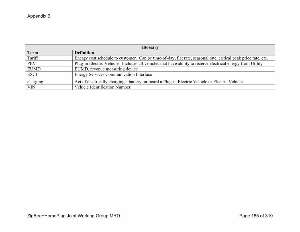
Appendix B
ZigBee+HomePlug Joint Working Group MRD Page 185 of 310
GlossaryTerm DefinitionTariff Energy cost schedule to customer. Can be timeofday, flat rate, seasonal rate, critical peak price rate, etc.PEV Plugin Electric Vehicle. Includes all vehicles that have ability to receive electrical energy from UtilityEUMD EUMD, revenue measuring deviceESCI Energy Services Communication Interfacecharging Act of electrically charging a battery onboard a Plugin Electric Vehicle or Electric VehicleVIN Vehicle Identification Number

Appendix B
ZigBee+HomePlug Joint Working Group MRD Page 186 of 310
c.PEV Use Case 2 Customer connects Plugin Electric Vehicle (PEV) to premise energy portalUse Case TitleCustomer connects Plugin Electric Vehicle (PEV) to premise energy portal
Use Case Summary
Customers are interested in fueling vehicles with electricity. Electric Vehicles (EV) and Plugin Electric Vehicles (PEV) are emerging transportation options for customers. Electric utilities desire to support these emerging loads with electricity at “off peak” times when energy costs are low and generation and power delivery assets are underutilized. PEV manufacturers are interested in working with utilities to develop customer rates/programs which could provide customers with an increased incentive to purchase a PEV. Within a utility service territory, the customer can plug in a PEV to receive a charge of electrical energy at his premise or plug in at another premise location. The Utility may offer the Customer a PEV tariff that provides a low rate for offpeak charging and a higher rate for onpeak charging. Each time the PEV is charged, Customers who have enrolled in a PEV program will exchange account and energy information. Energy supplied to the PEV is reported to the utility for billing and presentation to the Customer.
Use Case Detailed Narrative
Customers are interested in fueling vehicles with electricity. Electric Vehicles (EV) and Plugin Electric Vehicles (PEV) are emerging transportation options for customers. Electric utilities desire to support these emerging loads with electricity at “off peak” times when energy costs are low and generation and power delivery assets are underutilized. PEV manufacturers are interested in working with utilities to develop customer rates/programs which could provide customers with an increased incentive to purchase a PEV. Utilities may offer the Customer a PEV tariff that provides a low rate for offpeak charging and a higher rate for onpeak charging.
The vehicle can connect to the grid using either of the following:
! Electric Vehicle Supply Equipment (EVSE) Cordset – The cordset (described in J1772) would be used for convenience charging that is expected to connect to either a 15A or 20A 120V outlet
! Electric Vehicle Supply Equipment (EVSE) at the premise – It is expected that a premise mounted EVSE would be connected to a 240V service
! DC Premise Electric Vehicle Supply Equipment (EVSE)

Appendix B
ZigBee+HomePlug Joint Working Group MRD Page 187 of 310
Upon plugging a PEV using either a EVSE cordset (120V) or into Premise Mounted EVSE (240V), a communication session is initiated between the local Energy Services Communication Interface (ESCI) located at the premise and the PEV. The Utility validates that the Customer and the PEV ID (and/or Premise ID) are enrolled in a valid PEV program and that the there is correlation between the ESCI and the Energy Portal or Premise Mounted EVSE (in the case of Premise Mounted EVSE, the premise EVSE is already connected to the premise). That is, the premise associated to the ESCI and the charging PEV are the same. Upon validation, PEV charging begins, and an End Use Measurement Device (EUMD) tracks electricity supplied during the charging session. If communications cannot be established, or if PEV fails validation, charging will continue; however, no special PEV incentive will be applied. Upon termination of charging session, the End Use Measurement Device logs the charging session information and reports data to the utility for billing and presentation to the Customer. This use case covers five scenarios:
1) Customer connects PEV to energy portal at his premise location
2) Customer connects PEV to energy portal at another premise and premise customer pays for energy use
3) Customer connects PEV to energy portal at another premise and PEV customer pays for energy use
4) Customer connects PEV to energy portal at another premise outside the enrolled Utility's service territory
5) Nonenrolled PEV (or Customer with noncommunicating PEV) connects PEV to energy portal
6) Customer charges PEV at public location, Multi family Dwelling, and Workplace infrastructure
The situation related to public charging is covered implicitly in scenarios 2 and 3. Apartment building/ Multitenant situations can be covered by scenarios 1, 2, or 3.
Business Rules and Assumptions! High level assumption that PEV and utility have communications capabilities. For a foreign utility scenario (Scenario 3.4), assumption is
that roaming utility also has communications capabilities.
! In the absence or failure of PEVutility communications, or if PEV ID validation fails, PEV charging will always proceed; however, without the incentive rates and with all energy charges accruing to the premise customer according to the premise customer’s default rate/service plan.
! The PEV charging process for this use case can only be applied to customers that have already enrolled in a utility PEV program and have registered one or more PEVs in advance of charging. The enrollment and initial registration scenarios will be covered in a separate use case (Use Case P1). Steps for repeat binding of PEV to premise are also covered in Use Case P1.
! The customer awareness of the utility and vehicle programs is prompted by both the utility providers and the vehicle manufacturers.

Appendix B
ZigBee+HomePlug Joint Working Group MRD Page 188 of 310
o The utility offers PEV programs and services for its customers and will provide the necessary support processes for enrollment, communications, and billing
o The Vehicle manufacturers would provide information to the customer about fuel and/or emission gains of the vehicles offered and promote the utility and convenience of connecting to the grid
! Utility shall maintain information on all Customers and PEVs enrolled in the PEV programs, including demand side management programs, associated PHEV IDs, customer IDs, and premise IDs
! End Use Measurement Device (EUMD), either fixed or mobile, is always available for energy validation of PEV charging. If not available, charging will proceed, but with limitations on incentive rates and with all energy charges accruing to the premise customer. This may or may not prevent certain charging status indicators / metrics being available to customer for presentation/display purposes.
! End Use Measurement Device (EUMD) function can be inclusively located anywhere in a zone from the PEV and the branch circuit panel connection.
! Unenrolled PEV is prohibited from binding to Utility devices or network (Energy Services Communication Interface). However, PEV charging will be able to proceed with the assumptions already documented.
! Foreign utility scenario (Scenario 3.4) assumes the existence of a crossutility clearinghouse (available to all utilities) which can reconcile roaming utility PEV charging between premise customer of one utility and PEV operator/customer of a different utility. The concept of portability of multiple separate utility customers (with separate utility accounts) across a given PEV on a regular basis (e.g., rental car scenario) is not explicitly considered in this use case. This may be covered in a future use case.
! The PEV & Utility will communicate to implement one or more the following Utility programs (details of which are covered in section 3)
o Time of Use (TOU) pricing demand side management programs are when the customer has agreed to limit charges to the utility schedule for load balancing. (e.g., offpeak, midpeak, onpeak, etc.).
o Discrete Event demand side management program (Direct Load Control)o Periodic/Hourly Pricing Price Response programo Active Load Management program
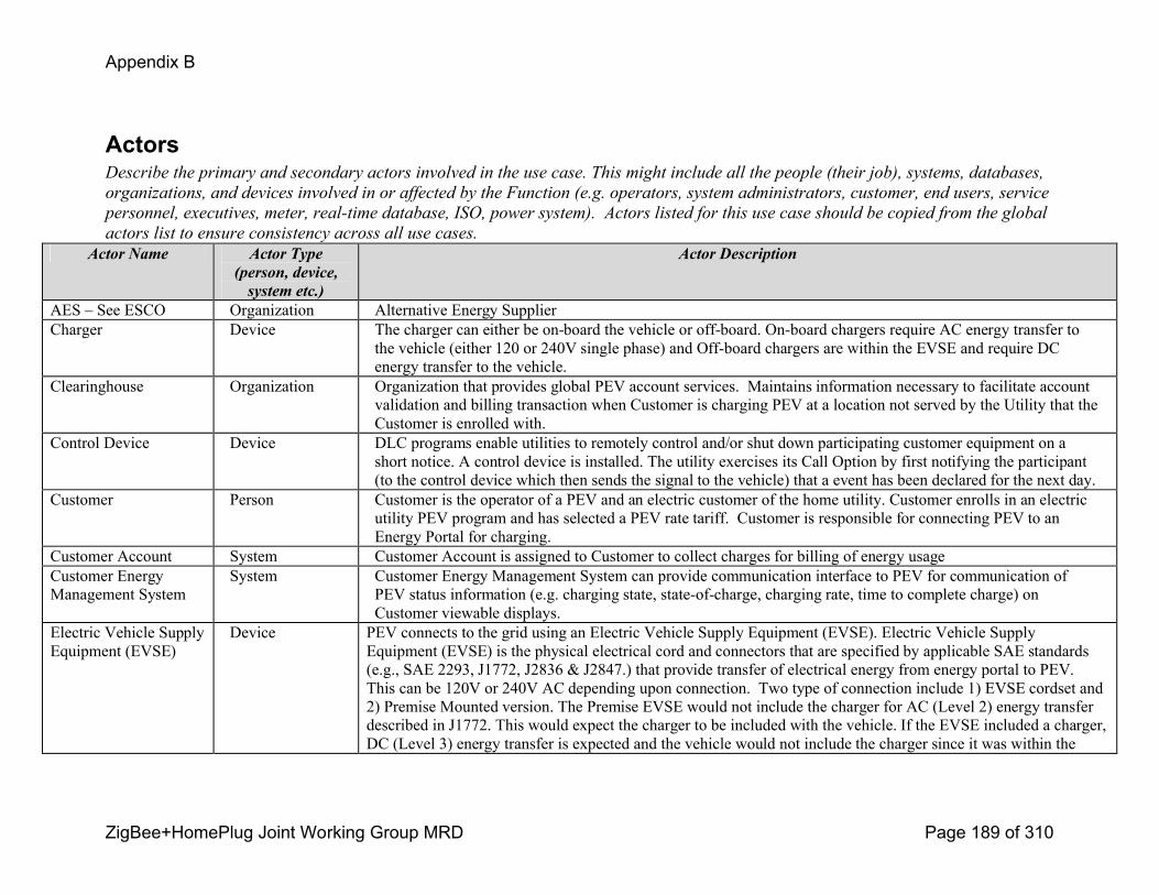
Appendix B
ZigBee+HomePlug Joint Working Group MRD Page 189 of 310
ActorsDescribe the primary and secondary actors involved in the use case. This might include all the people (their job), systems, databases,
organizations, and devices involved in or affected by the Function (e.g. operators, system administrators, customer, end users, service
personnel, executives, meter, realtime database, ISO, power system). Actors listed for this use case should be copied from the global
actors list to ensure consistency across all use cases.
Actor Name Actor Type (person, device, system etc.)
Actor Description
AES – See ESCO Organization Alternative Energy SupplierCharger Device The charger can either be onboard the vehicle or offboard. Onboard chargers require AC energy transfer to
the vehicle (either 120 or 240V single phase) and Offboard chargers are within the EVSE and require DC energy transfer to the vehicle.
Clearinghouse Organization Organization that provides global PEV account services. Maintains information necessary to facilitate account validation and billing transaction when Customer is charging PEV at a location not served by the Utility that the Customer is enrolled with.
Control Device Device DLC programs enable utilities to remotely control and/or shut down participating customer equipment on a short notice. A control device is installed. The utility exercises its Call Option by first notifying the participant (to the control device which then sends the signal to the vehicle) that a event has been declared for the next day.
Customer Person Customer is the operator of a PEV and an electric customer of the home utility. Customer enrolls in an electric utility PEV program and has selected a PEV rate tariff. Customer is responsible for connecting PEV to an Energy Portal for charging.
Customer Account System Customer Account is assigned to Customer to collect charges for billing of energy usageCustomer Energy Management System
System Customer Energy Management System can provide communication interface to PEV for communication of PEV status information (e.g. charging state, stateofcharge, charging rate, time to complete charge) on Customer viewable displays.
Electric Vehicle Supply Equipment (EVSE)
Device PEV connects to the grid using an Electric Vehicle Supply Equipment (EVSE). Electric Vehicle Supply Equipment (EVSE) is the physical electrical cord and connectors that are specified by applicable SAE standards (e.g., SAE 2293, J1772, J2836 & J2847.) that provide transfer of electrical energy from energy portal to PEV. This can be 120V or 240V AC depending upon connection. Two type of connection include 1) EVSE cordset and 2) Premise Mounted version. The Premise EVSE would not include the charger for AC (Level 2) energy transfer described in J1772. This would expect the charger to be included with the vehicle. If the EVSE included a charger, DC (Level 3) energy transfer is expected and the vehicle would not include the charger since it was within the
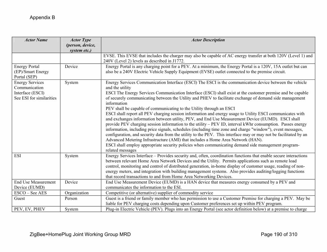
Appendix B
ZigBee+HomePlug Joint Working Group MRD Page 190 of 310
Actor Name Actor Type (person, device, system etc.)
Actor Description
EVSE. This EVSE that includes the charger may also be capable of AC energy transfer at both 120V (Level 1) and 240V (Level 2) levels as described in J1772.
Energy Portal (EP)/Smart Energy Portal (SEP)
Device Energy Portal is any charging point for a PEV. At a minimum, the Energy Portal is a 120V, 15A outlet but can also be a 240V Electric Vehicle Supply Equipment (EVSE) outlet connected to the premise circuit.
Energy Services Communication Interface (ESCI)See ESI for similarities
System Energy Services Communication Interface (ESCI) The ESCI is the communication device between the vehicle and the utilityESCI The Energy Services Communication Interface (ESCI) shall exist at the customer premise and be capable of securely communicating between the Utility and PHEV to facilitate exchange of demand side management informationPEV shall be capable of communicating to the Utility through an ESCIESCI shall report all PEV charging session information and energy usage to Utility ESCI communicates with and exchanges information between utility, PEV, and End Use Measurement Device (EUMD). ESCI shall provide PEV charging session information to the utility – PEV ID, interval kWhr consumption. Passes energy information, including price signals, schedules (including time zone and charge "window"), event messages, configuration, and security data from the utility to the PEV. This interface may or may not be facilitated by an Advanced Metering Infrastructure (AMI) that includes a Home Area Network (HAN). ESCI shall employ appropriate security policies when communicating demand side management programrelated messages
ESI System Energy Services Interface – Provides security and, often, coordination functions that enable secure interactions between relevant Home Area Network Devices and the Utility. Permits applications such as remote load control, monitoring and control of distributed generation, inhome display of customer usage, reading of nonenergy meters, and integration with building management systems. Also provides auditing/logging functions that record transactions to and from Home Area Networking Devices.
End Use Measurement Device (EUMD)
Device End Use Measurement Device (EUMD) is a HAN device that measures energy consumed by a PEV and communicates the information to the ESI.
ESCO – See AES Organization Competitive (or alternative) supplier of commodity serviceGuest Person Guest is a friend or family member who has permission to use a Customer Premise for charging a PEV. May be
liable for PEV charging costs depending upon Customer preferences set up within PEV program.PEV, EV, PHEV System Plugin Electric Vehicle (PEV). Plugs into an Energy Portal (see actor definition below) at a premise to charge
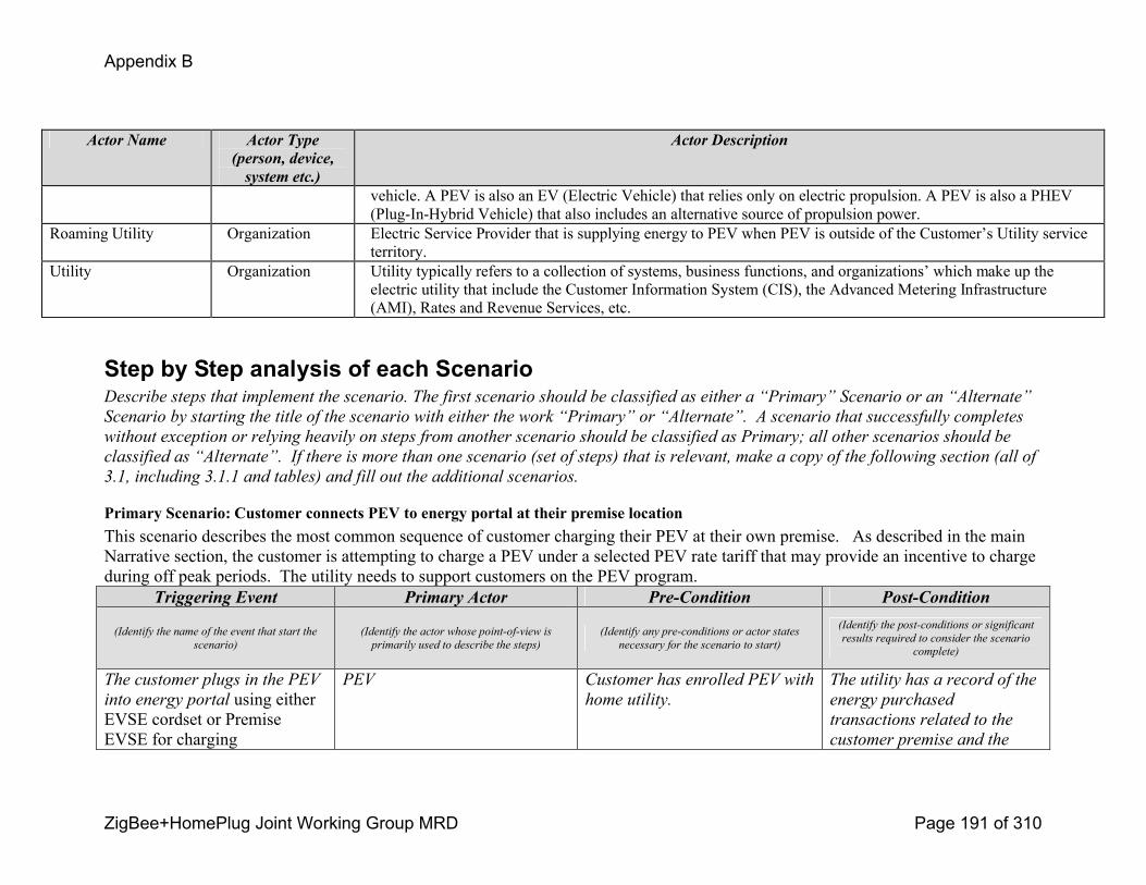
Appendix B
ZigBee+HomePlug Joint Working Group MRD Page 191 of 310
Actor Name Actor Type (person, device, system etc.)
Actor Description
vehicle. A PEV is also an EV (Electric Vehicle) that relies only on electric propulsion. A PEV is also a PHEV (PlugInHybrid Vehicle) that also includes an alternative source of propulsion power.
Roaming Utility Organization Electric Service Provider that is supplying energy to PEV when PEV is outside of the Customer’s Utility service territory.
Utility Organization Utility typically refers to a collection of systems, business functions, and organizations’ which make up the electric utility that include the Customer Information System (CIS), the Advanced Metering Infrastructure (AMI), Rates and Revenue Services, etc.
Step by Step analysis of each ScenarioDescribe steps that implement the scenario. The first scenario should be classified as either a “Primary” Scenario or an “Alternate”
Scenario by starting the title of the scenario with either the work “Primary” or “Alternate”. A scenario that successfully completes
without exception or relying heavily on steps from another scenario should be classified as Primary; all other scenarios should be
classified as “Alternate”. If there is more than one scenario (set of steps) that is relevant, make a copy of the following section (all of
3.1, including 3.1.1 and tables) and fill out the additional scenarios.
Primary Scenario: Customer connects PEV to energy portal at their premise location This scenario describes the most common sequence of customer charging their PEV at their own premise. As described in the main Narrative section, the customer is attempting to charge a PEV under a selected PEV rate tariff that may provide an incentive to charge during off peak periods. The utility needs to support customers on the PEV program.
Triggering Event Primary Actor PreCondition PostCondition
(Identify the name of the event that start the
scenario)
(Identify the actor whose pointofview is
primarily used to describe the steps)
(Identify any preconditions or actor states
necessary for the scenario to start)
(Identify the postconditions or significant
results required to consider the scenario
complete)
The customer plugs in the PEV
into energy portal using either EVSE cordset or Premise EVSE for charging
PEV Customer has enrolled PEV with
home utility.
The utility has a record of the
energy purchased
transactions related to the
customer premise and the
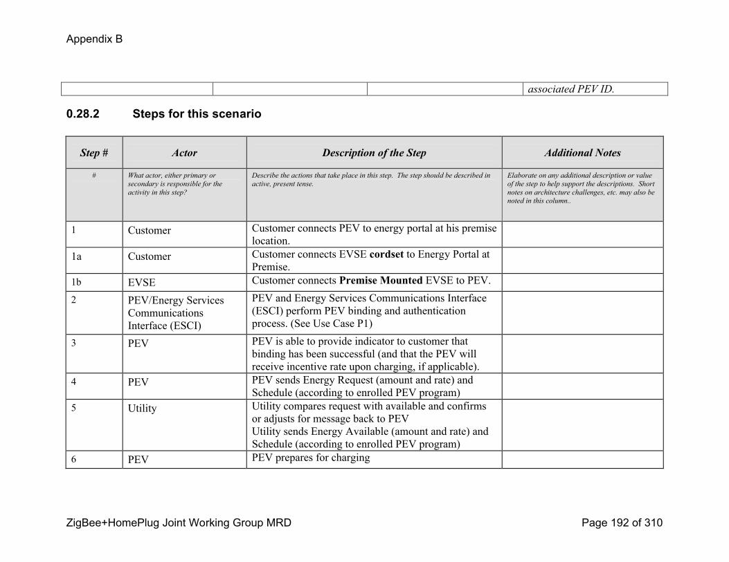
Appendix B
ZigBee+HomePlug Joint Working Group MRD Page 192 of 310
associated PEV ID.
0.28.2 Steps for this scenario
Step # Actor Description of the Step Additional Notes
# What actor, either primary or
secondary is responsible for the
activity in this step?
Describe the actions that take place in this step. The step should be described in
active, present tense.
Elaborate on any additional description or value
of the step to help support the descriptions. Short
notes on architecture challenges, etc. may also be
noted in this column..
1 Customer Customer connects PEV to energy portal at his premiselocation.
1a Customer Customer connects EVSE cordset to Energy Portal at Premise.
1b EVSE Customer connects Premise Mounted EVSE to PEV.
2 PEV/Energy Services Communications Interface (ESCI)
PEV and Energy Services Communications Interface (ESCI) perform PEV binding and authentication process. (See Use Case P1)
3 PEV PEV is able to provide indicator to customer that binding has been successful (and that the PEV will receive incentive rate upon charging, if applicable).
4 PEV PEV sends Energy Request (amount and rate) and Schedule (according to enrolled PEV program)
5 Utility Utility compares request with available and confirms or adjusts for message back to PEV Utility sends Energy Available (amount and rate) and Schedule (according to enrolled PEV program)
6 PEV PEV prepares for charging

Appendix B
ZigBee+HomePlug Joint Working Group MRD Page 193 of 310
Step # Actor Description of the Step Additional Notes
7 PEV PEV begins charging based on Customerselected preferences. Charging may be delayed based upon Customer preferences or grid reliability criteria (e.g., offpeak economy charging, demand response event underway, short, randomized charging delay to promote grid stability, etc.)
The vehicle needs to record the energy delivered as a running total for the event. This would be a reference to be compared with the EUMD total. The EUMD has logged the actual energy flow accumulation for the utility
8 End Use Measurement Device
EUMD, either fixed or mobile, records charging information and energy supplied to PEV for each charging session. Charging information includes PEV ID, Premise ID, energy usage, and time stamp for each metering interval.
9 End Use Measurement Device
EUMD communicates to the ESI using the Energy Services Communication Interface the energy supplied to PEV for each charging session.
This communication could be on a periodic basis during charging, upon vehicle unplug from energy portal, or a combination of the two.
See Issue 5.0 (Section 6)
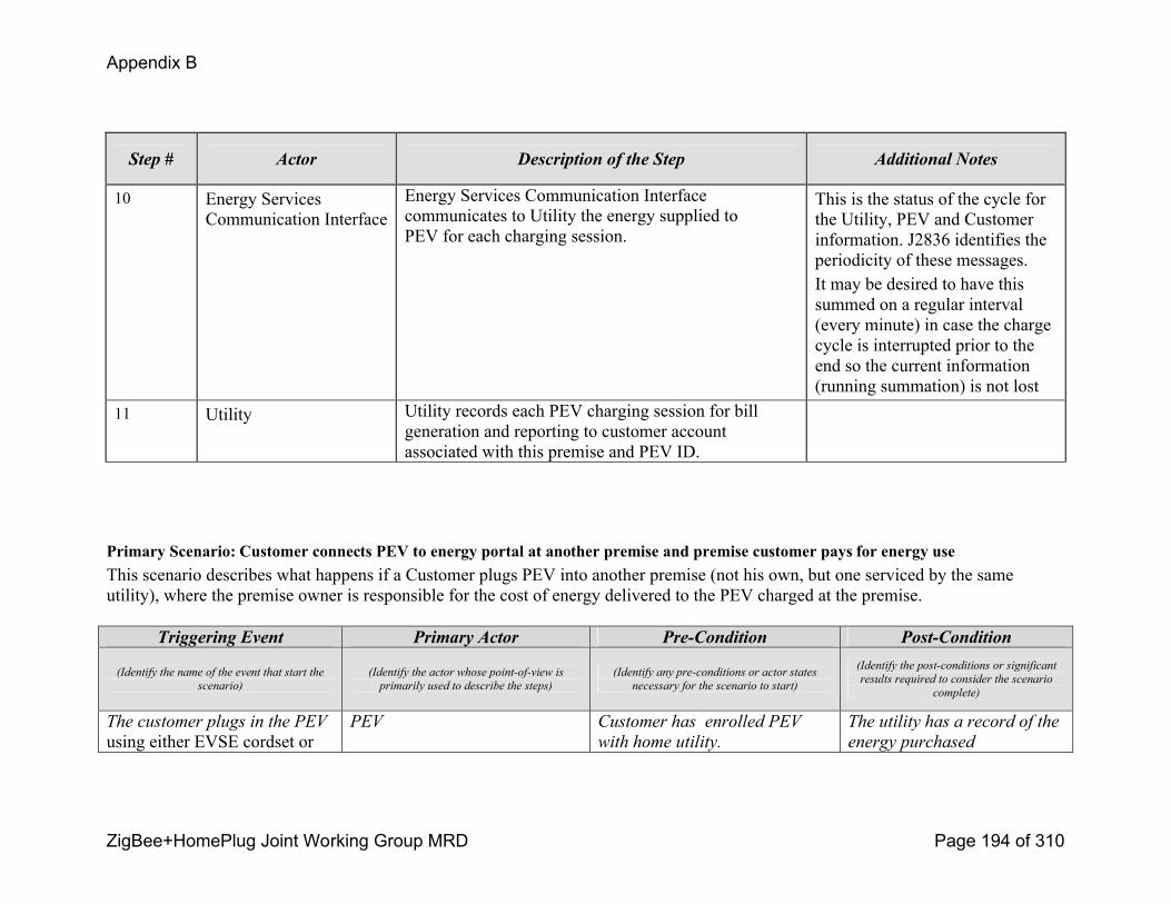
Appendix B
ZigBee+HomePlug Joint Working Group MRD Page 194 of 310
Step # Actor Description of the Step Additional Notes
10 Energy Services Communication Interface
Energy Services Communication Interfacecommunicates to Utility the energy supplied to PEV for each charging session.
This is the status of the cycle for the Utility, PEV and Customer information. J2836 identifies the periodicity of these messages. It may be desired to have this summed on a regular interval (every minute) in case the charge cycle is interrupted prior to the end so the current information (running summation) is not lost
11 Utility Utility records each PEV charging session for bill generation and reporting to customer account associated with this premise and PEV ID.
Primary Scenario: Customer connects PEV to energy portal at another premise and premise customer pays for energy use This scenario describes what happens if a Customer plugs PEV into another premise (not his own, but one serviced by the same utility), where the premise owner is responsible for the cost of energy delivered to the PEV charged at the premise.
Triggering Event Primary Actor PreCondition PostCondition
(Identify the name of the event that start the
scenario)
(Identify the actor whose pointofview is
primarily used to describe the steps)
(Identify any preconditions or actor states
necessary for the scenario to start)
(Identify the postconditions or significant
results required to consider the scenario
complete)
The customer plugs in the PEV
using either EVSE cordset or PEV Customer has enrolled PEV
with home utility.
The utility has a record of the
energy purchased
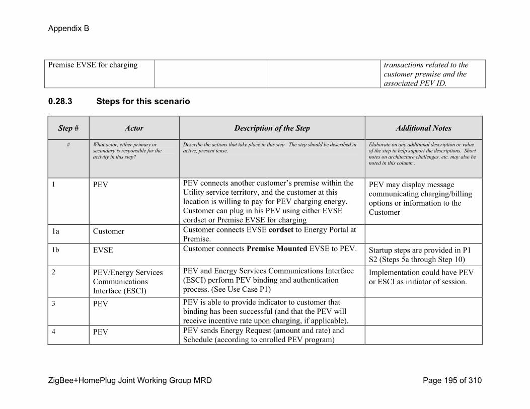
Appendix B
ZigBee+HomePlug Joint Working Group MRD Page 195 of 310
Premise EVSE for charging transactions related to the
customer premise and the
associated PEV ID.
0.28.3 Steps for this scenario.
Step # Actor Description of the Step Additional Notes
# What actor, either primary or
secondary is responsible for the
activity in this step?
Describe the actions that take place in this step. The step should be described in
active, present tense.
Elaborate on any additional description or value
of the step to help support the descriptions. Short
notes on architecture challenges, etc. may also be
noted in this column..
1 PEV PEV connects another customer’s premise within the Utility service territory, and the customer at this location is willing to pay for PEV charging energy. Customer can plug in his PEV using either EVSE cordset or Premise EVSE for charging
PEV may display message communicating charging/billing options or information to the Customer
1a Customer Customer connects EVSE cordset to Energy Portal at Premise.
1b EVSE Customer connects Premise Mounted EVSE to PEV. Startup steps are provided in P1 S2 (Steps 5a through Step 10)
2 PEV/Energy Services Communications Interface (ESCI)
PEV and Energy Services Communications Interface (ESCI) perform PEV binding and authentication process. (See Use Case P1)
Implementation could have PEV or ESCI as initiator of session.
3 PEV PEV is able to provide indicator to customer that binding has been successful (and that the PEV will receive incentive rate upon charging, if applicable).
4 PEV PEV sends Energy Request (amount and rate) and Schedule (according to enrolled PEV program)

Appendix B
ZigBee+HomePlug Joint Working Group MRD Page 196 of 310
Step # Actor Description of the Step Additional Notes
5 Utility Utility compares request with available and confirms or adjusts for message back to PEV Utility sends Energy Available (amount and rate) and Schedule (according to enrolled PEV program)
6 PEV PEV prepares for charging
7 PEV PEV begins charging based on Customerselected preferences. Charging may be delayed based upon Customer preferences or grid reliability criteria (e.g., offpeak economy charging, demand response event underway, short, randomized charging delay to promote grid stability, etc.)
The vehicle needs to record the energy delivered as a running total for the event. This would be a reference to be compared with the EUMD total. The EUMD has logged the actual energy flow accumulation for the utility
8 End Use Measurement Device
EUMD, either fixed or mobile, records charging information and energy supplied to PEV for each charging session. Charging information includes PEV ID, Premise ID, energy usage, and time stamp for each metering interval.
9 End Use Measurement Device
EUMD communicates to the ESI using the Energy Services Communication Interface the energy supplied to PEV for each charging session.
This communication could be on a periodic basis during charging, upon vehicle unplug from energy portal, or a combination of the two.
See Issue 5.0 (Section 6)
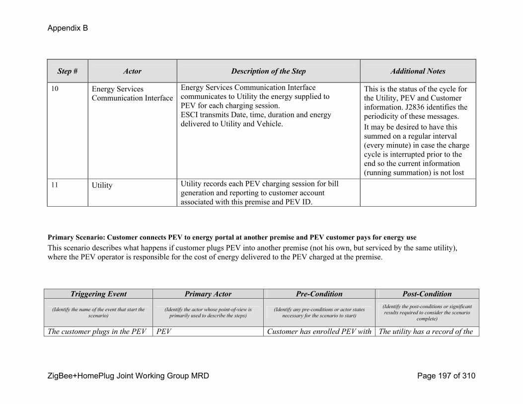
Appendix B
ZigBee+HomePlug Joint Working Group MRD Page 197 of 310
Step # Actor Description of the Step Additional Notes
10 Energy Services Communication Interface
Energy Services Communication Interfacecommunicates to Utility the energy supplied to PEV for each charging session.ESCI transmits Date, time, duration and energy delivered to Utility and Vehicle.
This is the status of the cycle for the Utility, PEV and Customer information. J2836 identifies the periodicity of these messages. It may be desired to have this summed on a regular interval (every minute) in case the charge cycle is interrupted prior to the end so the current information (running summation) is not lost
11 Utility Utility records each PEV charging session for bill generation and reporting to customer account associated with this premise and PEV ID.
Primary Scenario: Customer connects PEV to energy portal at another premise and PEV customer pays for energy useThis scenario describes what happens if customer plugs PEV into another premise (not his own, but serviced by the same utility), where the PEV operator is responsible for the cost of energy delivered to the PEV charged at the premise.
Triggering Event Primary Actor PreCondition PostCondition
(Identify the name of the event that start the
scenario)
(Identify the actor whose pointofview is
primarily used to describe the steps)
(Identify any preconditions or actor states
necessary for the scenario to start)
(Identify the postconditions or significant
results required to consider the scenario
complete)
The customer plugs in the PEV PEV Customer has enrolled PEV with The utility has a record of the

Appendix B
ZigBee+HomePlug Joint Working Group MRD Page 198 of 310
using either EVSE cordset or Premise EVSE for charging
home utility. energy purchased
transactions related to the
customer premise and the
associated PEV ID.
0.28.4 Steps for this scenario
Step # Actor Description of the Step Additional Notes
# What actor, either primary or secondary is
responsible for the activity in this step?
Describe the actions that take place in this step. The step should be described in active,
present tense.
Elaborate on any additional description or value of the
step to help support the descriptions. Short notes on
architecture challenges, etc. may also be noted in this
column..
1 PEV PEV connects at another customer premise within the Utility service territory. PEV owner will pay for charging. Customer can plug in his PEV using either EVSE cordset or Premise EVSE for charging
PEV may display message communicating charging/billing options or information to the Customer.
1a Customer Customer connects EVSE cordset to Energy Portal at Premise.
Startup steps are provided in P1 S1 (Steps 5a through Step 10)
1b EVSE Customer connects Premise Mounted EVSE to PEV. Startup steps are provided in P1 S2 (Steps 5a through Step 10)
2 PEV/Energy Services Communications Interface (ESCI)
PEV and Energy Services Communications Interface (ESCI) perform PEV binding and authentication process. (See Use Case P1)
Implementation could have PEV or ESCI as initiator of session.
3 PEV PEV is able to provide indicator to customer that binding has been successful (and that the PEV will receive incentive rate upon charging, if applicable).
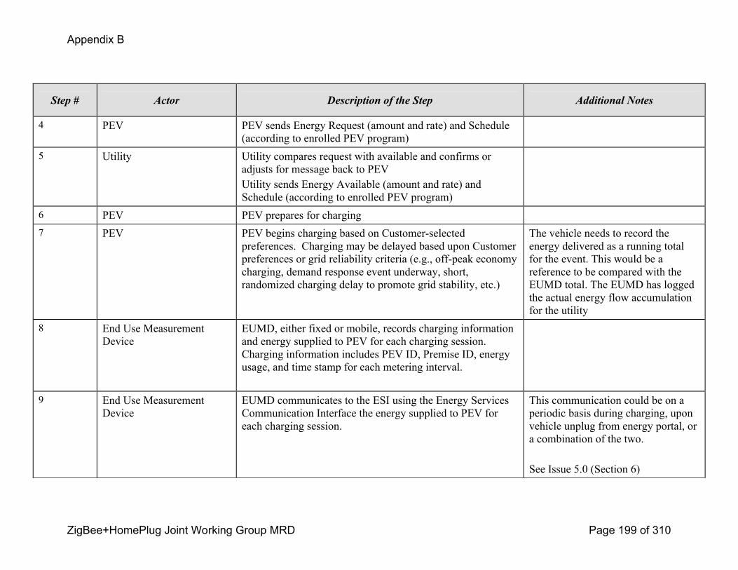
Appendix B
ZigBee+HomePlug Joint Working Group MRD Page 199 of 310
Step # Actor Description of the Step Additional Notes
4 PEV PEV sends Energy Request (amount and rate) and Schedule (according to enrolled PEV program)
5 Utility Utility compares request with available and confirms or adjusts for message back to PEV Utility sends Energy Available (amount and rate) and Schedule (according to enrolled PEV program)
6 PEV PEV prepares for charging7 PEV PEV begins charging based on Customerselected
preferences. Charging may be delayed based upon Customer preferences or grid reliability criteria (e.g., offpeak economy charging, demand response event underway, short, randomized charging delay to promote grid stability, etc.)
The vehicle needs to record the energy delivered as a running total for the event. This would be a reference to be compared with the EUMD total. The EUMD has logged the actual energy flow accumulation for the utility
8 End Use Measurement Device
EUMD, either fixed or mobile, records charging information and energy supplied to PEV for each charging session. Charging information includes PEV ID, Premise ID, energy usage, and time stamp for each metering interval.
9 End Use Measurement Device
EUMD communicates to the ESI using the Energy Services Communication Interface the energy supplied to PEV for each charging session.
This communication could be on a periodic basis during charging, upon vehicle unplug from energy portal, or a combination of the two.
See Issue 5.0 (Section 6)

Appendix B
ZigBee+HomePlug Joint Working Group MRD Page 200 of 310
Step # Actor Description of the Step Additional Notes
10 Energy Services Communication Interface
Energy Services Communication Interface communicates to Utility the energy supplied to PEV for each charging session.ESCI transmits Date, time, duration and energy delivered to Utility and Vehicle.
This is the status of the cycle for the Utility, PEV and Customer information. J2836 identifies the periodicity of these messages. It may be desired to have this summed on a regular interval (every minute) in case the charge cycle is interrupted prior to the end so the current information (running summation) is not lost
11 Utility Utility records each PEV charging session for bill generation and reporting to customer account associated with this premise and PEV ID.
Primary Scenario: Customer connects PEV to energy portal at another premise outside the enrolled Utility’s service territory This scenario describes what happens if customer plugs PEV into another premise (not his own, and not serviced by the same utility (i.e.. roaming utility), where the PEV operator is responsible for the cost of energy delivered to the PEV charged at the premise.
Triggering Event Primary Actor PreCondition PostCondition
(Identify the name of the event that start the
scenario)
(Identify the actor whose pointofview is
primarily used to describe the steps)
(Identify any preconditions or actor states
necessary for the scenario to start)
(Identify the postconditions or significant
results required to consider the scenario
complete)
The customer plugs in the PEV
into energy portal
PEV Customer has enrolled PEV with
home utility.
Both home and foreign/roaming
utility participate in interutility
The foreign/roaming utility
and the clearinghouse has a
record of the energy
purchased transactions
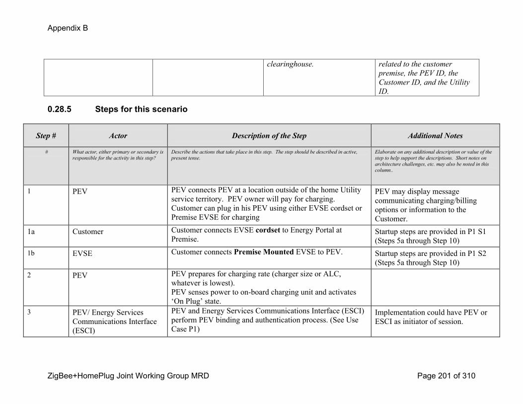
Appendix B
ZigBee+HomePlug Joint Working Group MRD Page 201 of 310
clearinghouse. related to the customer
premise, the PEV ID, the
Customer ID, and the Utility
ID.
0.28.5 Steps for this scenario
Step # Actor Description of the Step Additional Notes
# What actor, either primary or secondary is
responsible for the activity in this step?
Describe the actions that take place in this step. The step should be described in active,
present tense.
Elaborate on any additional description or value of the
step to help support the descriptions. Short notes on
architecture challenges, etc. may also be noted in this
column..
1 PEV PEV connects PEV at a location outside of the home Utility service territory. PEV owner will pay for charging. Customer can plug in his PEV using either EVSE cordset or Premise EVSE for charging
PEV may display message communicating charging/billing options or information to the Customer.
1a Customer Customer connects EVSE cordset to Energy Portal at Premise.
Startup steps are provided in P1 S1 (Steps 5a through Step 10)
1b EVSE Customer connects Premise Mounted EVSE to PEV. Startup steps are provided in P1 S2 (Steps 5a through Step 10)
2 PEV PEV prepares for charging rate (charger size or ALC, whatever is lowest).PEV senses power to onboard charging unit and activates ‘On Plug’ state.
3 PEV/ Energy Services Communications Interface (ESCI)
PEV and Energy Services Communications Interface (ESCI) perform PEV binding and authentication process. (See Use Case P1)
Implementation could have PEV or ESCI as initiator of session.

Appendix B
ZigBee+HomePlug Joint Working Group MRD Page 202 of 310
Step # Actor Description of the Step Additional Notes
4 PEV PEV ID is transmitted to ESCI. Unique PEV ID will ultimately support portability of charging, among other purposes.
5 ESCI ESCI maintains communication session and security between PEV and Roaming Utility. ESCI transmits request for validating PEV ID to Roaming Utility, including Premise ID.
6 Roaming Utility Roaming Utility checks PEV ID and Premise ID against internal database. When not found (because PEV is registered with home utility), Roaming utility forwards PEV ID and Roaming Utility ID to Clearinghouse for verification.
7 Clearinghouse Clearinghouse checks PEV database for PEV ID and finds corresponding Home Utility ID, and Home Utility Account/Premise ID.
Underlying assumption is that PEV has been registered with home utility and that both utilities participate in the clearinghouse.
8 Clearinghouse Clearinghouse transmits confirmed message to Roaming Utility, including PEV ID, Home Utility ID, and Home Utility Account/Premise ID.
See Issue 10.0 (Section 6)
9 Roaming Utility Roaming Utility transmits confirmed message via ESCI to End Use Measurement Device (EUMD) indicating successful binding with premise ESCI.
10 ESCI ESCI transmits confirmation message to PEV indicating successful communication session binding of PEV to Roaming Utility at PEV program tariff. PEV is able to provide indicator to customer that binding has been successful (and that he will receive incentive rate upon charging, if applicable).

Appendix B
ZigBee+HomePlug Joint Working Group MRD Page 203 of 310
Step # Actor Description of the Step Additional Notes
11 PEV PEV sends Energy Request (amount and rate) and Schedule (according to enrolled PEV program)
12 Utility Utility compares request with available and confirms or adjusts for message back to PEV Utility sends Energy Available (amount and rate) and Schedule (according to enrolled PEV program)
13 PEV PEV prepares for charging
14 PEV PEV begins charging based on Customer selected preferences. Charging may be delayed based upon Customer preferences or grid reliability criteria (e.g., offpeak economy charging, demand response event underway, short, randomized charging delay to promote grid stability, etc.)
The vehicle needs to record the energy delivered as a running total for the event. This would be a reference to be compared with the EUMD total. The EUMD has logged the actual energy flow accumulation for the utility
15 End Use Measurement Device
EUMD, either fixed or mobile, records charging information and energy supplied to PEV for each charging session. Charging information includes PEV ID, Premise ID, energy usage, and time stamp for each metering interval.
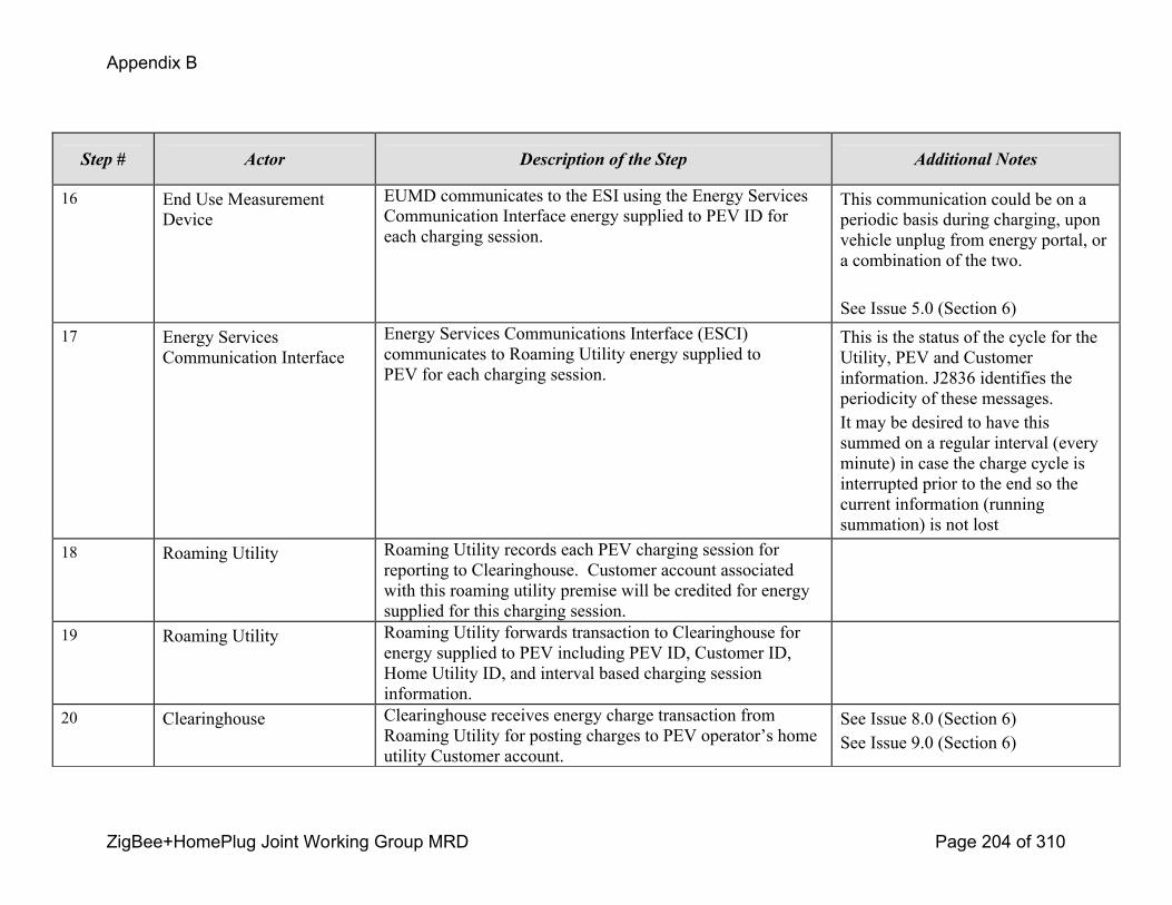
Appendix B
ZigBee+HomePlug Joint Working Group MRD Page 204 of 310
Step # Actor Description of the Step Additional Notes
16 End Use Measurement Device
EUMD communicates to the ESI using the Energy Services Communication Interface energy supplied to PEV ID for each charging session.
This communication could be on a periodic basis during charging, upon vehicle unplug from energy portal, or a combination of the two.
See Issue 5.0 (Section 6)17 Energy Services
Communication InterfaceEnergy Services Communications Interface (ESCI) communicates to Roaming Utility energy supplied to PEV for each charging session.
This is the status of the cycle for the Utility, PEV and Customer information. J2836 identifies the periodicity of these messages. It may be desired to have this summed on a regular interval (every minute) in case the charge cycle is interrupted prior to the end so the current information (running summation) is not lost
18 Roaming Utility Roaming Utility records each PEV charging session for reporting to Clearinghouse. Customer account associated with this roaming utility premise will be credited for energy supplied for this charging session.
19 Roaming Utility Roaming Utility forwards transaction to Clearinghouse for energy supplied to PEV including PEV ID, Customer ID, Home Utility ID, and interval based charging session information.
20 Clearinghouse Clearinghouse receives energy charge transaction from Roaming Utility for posting charges to PEV operator’s home utility Customer account.
See Issue 8.0 (Section 6)See Issue 9.0 (Section 6)

Appendix B
ZigBee+HomePlug Joint Working Group MRD Page 205 of 310
Primary Scenario: Nonenrolled PEV (or Customer with noncommunicating PEV) connects to energy portal This scenario describes what happens if an unenrolled PEV can communicate with local area network (e.g., LAN, HAN, PAN) or Customer has PEV that cannot communicate or cannot communicate with a specific Utility’s network.
Triggering Event Primary Actor PreCondition PostCondition
(Identify the name of the event that start the
scenario)
(Identify the actor whose pointofview is
primarily used to describe the steps)
(Identify any preconditions or actor states
necessary for the scenario to start)
(Identify the postconditions or significant
results required to consider the scenario
complete)
The customer plugs in the PEV
into energy portal
PEV Customer has a PEV, but is
unenrolled in a Utility PEV
program, has a non
communicating PEV, or both.
No communication session
established with Utility
network or devices. PEV
charges successfully with all
energy charges accruing to
charging premise account.
0.28.6 Steps for this scenario
Step # Actor Description of the Step Additional Notes
# What actor, either primary or secondary is
responsible for the activity in this step?
Describe the actions that take place in this step. The step should be described in active,
present tense.
Elaborate on any additional description or value of the
step to help support the descriptions. Short notes on
architecture challenges, etc. may also be noted in this
column..
1 PEV PEV connects to energy portal at any customer location. This could be in the PEV operator’s home utility service territory or in a foreign utility service territory.
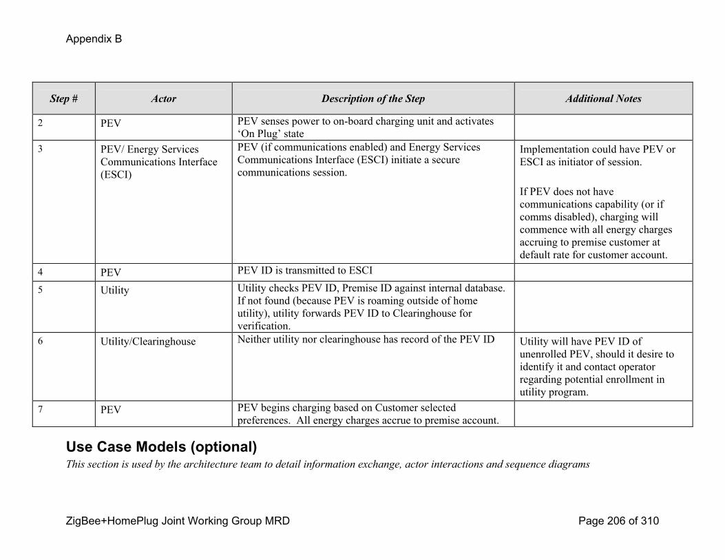
Appendix B
ZigBee+HomePlug Joint Working Group MRD Page 206 of 310
Step # Actor Description of the Step Additional Notes
2 PEV PEV senses power to onboard charging unit and activates ‘On Plug’ state
3 PEV/ Energy Services Communications Interface (ESCI)
PEV (if communications enabled) and Energy Services Communications Interface (ESCI) initiate a secure communications session.
Implementation could have PEV or ESCI as initiator of session.
If PEV does not have communications capability (or if comms disabled), charging will commence with all energy charges accruing to premise customer at default rate for customer account.
4 PEV PEV ID is transmitted to ESCI
5 Utility Utility checks PEV ID, Premise ID against internal database. If not found (because PEV is roaming outside of home utility), utility forwards PEV ID to Clearinghouse for verification.
6 Utility/Clearinghouse Neither utility nor clearinghouse has record of the PEV ID Utility will have PEV ID of unenrolled PEV, should it desire to identify it and contact operator regarding potential enrollment in utility program.
7 PEV PEV begins charging based on Customer selected preferences. All energy charges accrue to premise account.
Use Case Models (optional)This section is used by the architecture team to detail information exchange, actor interactions and sequence diagrams
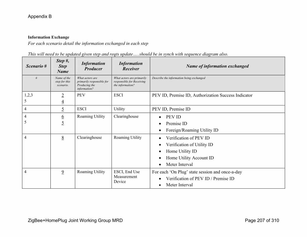
Appendix B
ZigBee+HomePlug Joint Working Group MRD Page 207 of 310
Information ExchangeFor each scenario detail the information exchanged in each step
This will need to be updated given step and reqts update…..should be in synch with sequence diagram also.
Scenario #Step #, Step Name
Information Producer
Information Receiver Name of information exchanged
# Name of the
step for this
scenario.
What actors are
primarily responsible for
Producing the
information?
What actors are primarily
responsible for Receiving
the information?
Describe the information being exchanged
1,2,35
24
PEV ESCI PEV ID, Premise ID, Authorization Success Indicator
4 5 ESCI Utility PEV ID, Premise ID45
65
Roaming Utility Clearinghouse ! PEV ID! Premise ID! Foreign/Roaming Utility ID
4 8 Clearinghouse Roaming Utility ! Verification of PEV ID! Verification of Utility ID! Home Utility ID! Home Utility Account ID! Meter Interval
4 9 Roaming Utility ESCI, End Use Measurement Device
For each ‘On Plug’ state session and onceaday! Verification of PEV ID / Premise ID! Meter Interval
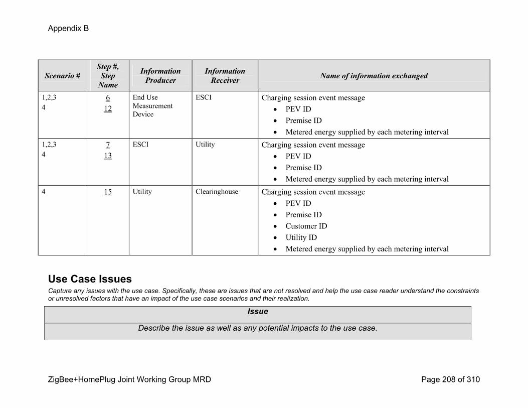
Appendix B
ZigBee+HomePlug Joint Working Group MRD Page 208 of 310
Scenario #Step #, Step Name
Information Producer
Information Receiver Name of information exchanged
1,2,34
612
End Use Measurement Device
ESCI Charging session event message! PEV ID! Premise ID! Metered energy supplied by each metering interval
1,2,34
713
ESCI Utility Charging session event message! PEV ID! Premise ID! Metered energy supplied by each metering interval
4 15 Utility Clearinghouse Charging session event message! PEV ID! Premise ID! Customer ID! Utility ID! Metered energy supplied by each metering interval
Use Case IssuesCapture any issues with the use case. Specifically, these are issues that are not resolved and help the use case reader understand the constraints or unresolved factors that have an impact of the use case scenarios and their realization.
Issue
Describe the issue as well as any potential impacts to the use case.

Appendix B
ZigBee+HomePlug Joint Working Group MRD Page 209 of 310
5.0 End Use Measurement Device (EUMD) communicates energy supplied to PEV to Energy Services Communication Interface for each charging session. A question arises: What triggers or invokes this communication session? Does this event get triggered upon the battery completing a full charge? Does this happen a termination of charge and PEV unplugs? If the session does not immediately, does the session take place next time a PEV charges in and can communicate to an ESCI?6.0 – Concern expressed about the viability of implementing a billing system for scenarios 2 and 3 that keeps track of usage for PEV charging at a nonPEV Operator/Customer premise and charges the PEV customer account & credits the premise Customer account correctly.7.0 – Need to determine what happens when communications is not successful between PEV and Utility. This may especially be an issue in case of roaming. Assumption is that with no communications, energy charges would accrue to premise account at default utility rate for that account (i.e. no incentive rates). Customer would not receive notification of successful binding/comms session in this case.8.0 – For home or foreign utility roaming, would need to consider what rates PEV operator would pay for usage outside of home premise, especially in a tiered rate environment. For example, would nonhome premise PEV usage count against (and be charged at rates for) PEV operator’s home premise baseline, charging premise customer’s baseline, or neither?9.0 – For foreign utility roaming, would need to consider what rates PEV operator would pay. Home utility’s rates, roaming utilities rates, special roaming rates, etc? Answer may be different depending on whether home or foreign utility has the higher energy prices. This would affect how clearinghouse accomplishes crossutility settlement.10.0 – Regarding the cross utility Clearinghouse for PEVs, further consideration needs to be taken to determine whether PEV ID/Customer ID information is actually stored at the clearinghouse, or if it is simply a facilitator of information exchange between utilities that allows for rapid, automated account validation/acknowledgement.
GlossaryInsert the terms and definitions relevant to this use case. Please ensure that any glossary item added to this list should be included in
the global glossary to ensure consistency between use cases.
GlossaryTerm DefinitionRate tariff Energy cost schedule to customer. Can be timeofday, flat rate, seasonal rate, critical peak price rate, etc.PEV Plugin Electric VehicleEUMD End Use Measurement Device, revenue measuring device

Appendix B
ZigBee+HomePlug Joint Working Group MRD Page 210 of 310
ESCI Energy Services Communication Interfacecharging Act of electrically charging a battery onboard a Plugin Electric Vehicle or Electric Vehicle
Appendix B
ZigBee+HomePlug Joint Working Group MRD Page 211 of 310
PEV Use Case 3 Utility provides services to Plugin Electric Vehicle (PEV) Customer
0.29 Use Case TitleUtility provides services to Plugin Electric Vehicle (PEV) Customer
0.30 Use Case SummaryThe Utility offers demand side management programs specifically for customers with PEVs to enroll in. Participants in the selected PEV demand side management program may respond to demand response requests by the Utility by reducing PEV load or shifting the time of day that the PEV is being charged. Scenarios for the following types of demand side management programs have been considered for this Use Case:
1) Customer is enrolled in a PEV TimeofUse (TOU) pricing demand side management program (e.g., offpeak, midpeak, onpeak, etc.)
2) Customer is enrolled in a PEV Discrete Event demand side management program (Direct Load Control)
3) Customer is enrolled in a PEV Periodic/Hourly Pricing Price Response program
4) Active load management – utility The selected demand side management program allows the customer to respond in different ways to the demand response request by Utility. Whenever a demand response request is initiated, the Utility notifies PEV Customers enrolled in applicable Utility PEV demand side management programs to encourage action. A variety of notification methods are selectable by the Customer (e.g., pager, email, text message on cell phone, web page, etc).
When the Customer plugs the PEV into the Energy Portal, which activates the PEV “OnPlug” State, a communication session is established between the PEV and the Utility via an Energy Services Communication Interface (ESCI) at the premise. The ESCI will forward discrete demand response event information or a dayahead periodic/hourly pricing table available from the Utility to the customer PEV. PEV charging proceeds based on Customerconfigurable charging preferences set inside the PEV. The Customer has the ability to override and optout of demand response events for the PEV. The Customer may receive a reduced incentive for exercising this option. The ESCI returns PEV charging status and energy supplied to the PEV back to the Utility from an End Use Measurement Device.
The Utility will measure (using data from the PEV End Use Measurement Device) the aggregate load reduction. This information can be fed back into a model used to determine the value of future load reduction requests.
Appendix B
ZigBee+HomePlug Joint Working Group MRD Page 212 of 310
0.31 Use Case Detailed Narrative
The Utility offers demand side management programs specifically for Customers with PEVs to enroll in. Participants in the selected PEV demand side management program may respond to requests by the Utility by reducing PEV load or shifting the time of day that the PEV is being charged. Scenarios for the following types of demand side management programs have been considered for this Use Case:
1) Customer is enrolled in a PEV TimeofUse (TOU) pricing demand side management program (e.g., offpeak, midpeak, onpeak, etc.)
2) Customer is enrolled in a PEV Discrete Event demand side management program (Direct Load Control)
3) Customer is enrolled in a PEV Periodic/Hourly Pricing Price Response program
The selected demand side management program allows the customer to respond in different ways to the demand response request by Utility. Whenever a demand response request is initiated, the Utility notifies PEV Customers enrolled in applicable Utility PEV demand side management programs to encourage action. A variety of notification methods are selectable by the Customer (e.g., pager, email, text message on cell phone, web page, etc).
PEV TimeofUseFor those customers enrolled in a PEV TimeofUse (TOU) pricing demand side management program, applicable energy prices and rate periods (e.g., offpeak, midpeak, onpeak, etc.) will be made known to the Customer and PEV. PEV initiates charging based on Customerdefined preference settings (considering peak/offpeak rate periods) in the PEV. PEV may not receive demand response discrete event notifications; however, some Customers enrolled in PEV TOU demand side management programs could also enroll in a Discrete Event demand side management program. Because no regular periodic communications between PEV and vehicle is required to support a basic PEV TOU pricing demand side management program, an explicit scenario for this option was not included in this use case. However, UtilitytoPEV communications for PEVs enrolled in a TOU demand side management program does offer other benefits (e.g., updated rates displayed in PEV).
PEV Discrete EventFor those customers enrolled in a PEV Discrete Event demand side management program, Utility sends a discrete event request to PEV based upon a prediction of energy supply and/or grid reliability concerns. Such a message may direct the PEV to discontinue PEV charging until the demand response event is over, or until the time duration allowed for the event expires.
PEV Periodic/Hourly Pricing

Appendix B
ZigBee+HomePlug Joint Working Group MRD Page 213 of 310
For those customers enrolled in a PEV Periodic/Hourly Pricing Price Response program, the utility will download dayahead 24 hour prices for each hour to the PEV. PEV charging proceeds based on Customerselected preference settings in the PEV.
Customer plugs PEV into Energy Portal to initiate charging. PEV senses power to onboard charging unit and activates ‘On Plug’ State. A communication session is established between the PEV and the Utility via an Energy Services Communication Interface (ESCI). ESCI handles communication session – including security – and transports all demand side management information between the PEV and Utility. PEV ID is transmitted to ESCI and on to Utility. Utility verifies PEV ID and Premise ID and sends back acknowledgement message. If PEV is enrolled in PEV demand side management program, Utility downloads discrete demand response event information or dayahead periodic/hourly pricing table to PEV via ESCI.
PEV charging proceeds based on Customer settable preferences. The customer has the ability to override and opt out of demand response events for the PEV through Customerconfigured preferences in the PEV. The customer may receive a reduced incentive for exercising this option. End Use Measurement Device records energy supplied to PEV for each charging session. End Use Measurement Device communicates energy supplied to PEV to ESCI, which in turn conveys this information to the Utility. Utility records each PEV charging session for bill generation and reporting.
The Utility will measure (using data from the End Use Measurement Device) the aggregate load reduction. This information can be fed back into a model used to determine the value of future load reduction requests.
Appendix B
ZigBee+HomePlug Joint Working Group MRD Page 214 of 310
0.32 Business Rules and Assumptions! High level assumption that PEV and utility have communications capabilities.
! Demand Response events will be distributed to PEVs via utilitymanaged communications infrastructure, with ESCI available at end points; other nonUtility (e.g., cellular, WiFi) communications mechanisms could be considered in additional scenarios.
! The demand side management scenarios for this use case can only be applied to Customers that have enrolled in a Utility PEV demand side management program and have registered one or many PEVs with the Utility. The enrollment and registration scenarios are covered in a separate Use Case (P1).
! End Use Measurement Device (EUMD), either fixed or mobile, is always available for energy validation of PEV charging. If not available, charging will proceed, but with limitations on incentive rates and with all energy charges accruing to the premise customer. This may or may not prevent certain charging status indicators / metrics being available to customer for presentation/display purposes.
! End Use Measurement Device (EUMD) function can be located anywhere in a zone from the PEV and the branch circuit panel connection.
ActorsDescribe the primary and secondary actors involved in the use case. This might include all the people (their job), systems, databases,
organizations, and devices involved in or affected by the Function (e.g. operators, system administrators, customer, end users, service
personnel, executives, meter, realtime database, ISO, power system). Actors listed for this use case should be copied from the global
actors list to ensure consistency across all use cases.
Actor Name Actor Type (person, device, system etc.)
Actor Description
AES – See ESCO Organization Alternative Energy SupplierCharger Device The charger can either be onboard the vehicle or offboard. Onboard chargers require AC energy transfer to
the vehicle (either 120 or 240V single phase) and Offboard chargers are within the EVSE and require DC energy transfer to the vehicle.
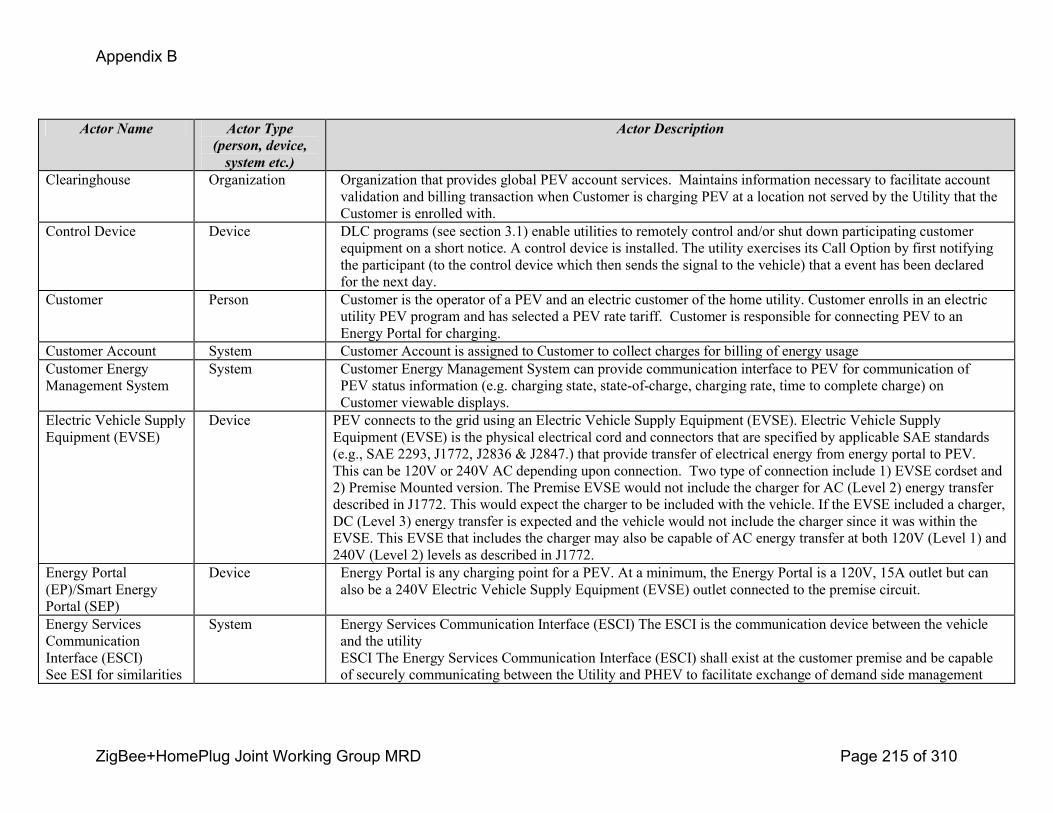
Appendix B
ZigBee+HomePlug Joint Working Group MRD Page 215 of 310
Actor Name Actor Type (person, device, system etc.)
Actor Description
Clearinghouse Organization Organization that provides global PEV account services. Maintains information necessary to facilitate account validation and billing transaction when Customer is charging PEV at a location not served by the Utility that the Customer is enrolled with.
Control Device Device DLC programs (see section 3.1) enable utilities to remotely control and/or shut down participating customer equipment on a short notice. A control device is installed. The utility exercises its Call Option by first notifying the participant (to the control device which then sends the signal to the vehicle) that a event has been declared for the next day.
Customer Person Customer is the operator of a PEV and an electric customer of the home utility. Customer enrolls in an electric utility PEV program and has selected a PEV rate tariff. Customer is responsible for connecting PEV to an Energy Portal for charging.
Customer Account System Customer Account is assigned to Customer to collect charges for billing of energy usageCustomer Energy Management System
System Customer Energy Management System can provide communication interface to PEV for communication of PEV status information (e.g. charging state, stateofcharge, charging rate, time to complete charge) on Customer viewable displays.
Electric Vehicle Supply Equipment (EVSE)
Device PEV connects to the grid using an Electric Vehicle Supply Equipment (EVSE). Electric Vehicle Supply Equipment (EVSE) is the physical electrical cord and connectors that are specified by applicable SAE standards (e.g., SAE 2293, J1772, J2836 & J2847.) that provide transfer of electrical energy from energy portal to PEV. This can be 120V or 240V AC depending upon connection. Two type of connection include 1) EVSE cordset and 2) Premise Mounted version. The Premise EVSE would not include the charger for AC (Level 2) energy transfer described in J1772. This would expect the charger to be included with the vehicle. If the EVSE included a charger, DC (Level 3) energy transfer is expected and the vehicle would not include the charger since it was within the EVSE. This EVSE that includes the charger may also be capable of AC energy transfer at both 120V (Level 1) and 240V (Level 2) levels as described in J1772.
Energy Portal (EP)/Smart Energy Portal (SEP)
Device Energy Portal is any charging point for a PEV. At a minimum, the Energy Portal is a 120V, 15A outlet but can also be a 240V Electric Vehicle Supply Equipment (EVSE) outlet connected to the premise circuit.
Energy Services Communication Interface (ESCI)See ESI for similarities
System Energy Services Communication Interface (ESCI) The ESCI is the communication device between the vehicle and the utilityESCI The Energy Services Communication Interface (ESCI) shall exist at the customer premise and be capable of securely communicating between the Utility and PHEV to facilitate exchange of demand side management
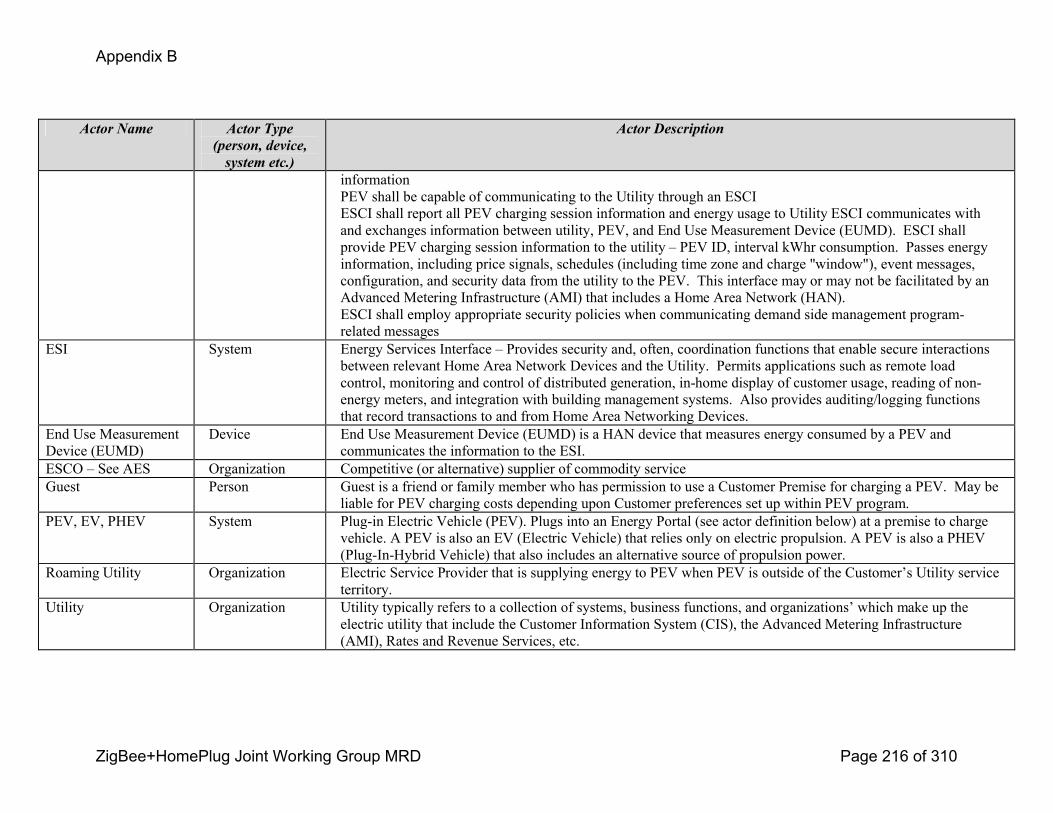
Appendix B
ZigBee+HomePlug Joint Working Group MRD Page 216 of 310
Actor Name Actor Type (person, device, system etc.)
Actor Description
informationPEV shall be capable of communicating to the Utility through an ESCIESCI shall report all PEV charging session information and energy usage to Utility ESCI communicates with and exchanges information between utility, PEV, and End Use Measurement Device (EUMD). ESCI shall provide PEV charging session information to the utility – PEV ID, interval kWhr consumption. Passes energy information, including price signals, schedules (including time zone and charge "window"), event messages, configuration, and security data from the utility to the PEV. This interface may or may not be facilitated by an Advanced Metering Infrastructure (AMI) that includes a Home Area Network (HAN). ESCI shall employ appropriate security policies when communicating demand side management programrelated messages
ESI System Energy Services Interface – Provides security and, often, coordination functions that enable secure interactions between relevant Home Area Network Devices and the Utility. Permits applications such as remote load control, monitoring and control of distributed generation, inhome display of customer usage, reading of nonenergy meters, and integration with building management systems. Also provides auditing/logging functions that record transactions to and from Home Area Networking Devices.
End Use Measurement Device (EUMD)
Device End Use Measurement Device (EUMD) is a HAN device that measures energy consumed by a PEV and communicates the information to the ESI.
ESCO – See AES Organization Competitive (or alternative) supplier of commodity serviceGuest Person Guest is a friend or family member who has permission to use a Customer Premise for charging a PEV. May be
liable for PEV charging costs depending upon Customer preferences set up within PEV program.PEV, EV, PHEV System Plugin Electric Vehicle (PEV). Plugs into an Energy Portal (see actor definition below) at a premise to charge
vehicle. A PEV is also an EV (Electric Vehicle) that relies only on electric propulsion. A PEV is also a PHEV (PlugInHybrid Vehicle) that also includes an alternative source of propulsion power.
Roaming Utility Organization Electric Service Provider that is supplying energy to PEV when PEV is outside of the Customer’s Utility service territory.
Utility Organization Utility typically refers to a collection of systems, business functions, and organizations’ which make up the electric utility that include the Customer Information System (CIS), the Advanced Metering Infrastructure (AMI), Rates and Revenue Services, etc.

Appendix B
ZigBee+HomePlug Joint Working Group MRD Page 217 of 310
End Use Measurement Device (EUMD) is always available for energy validation of PEV charging. If not available, charging will proceed, but with limitations on incentive rates and with all energy charges accruing to the premise customer. This may or may not prevent certain charging status indicators / metrics being available to customer for presentation/display purposes.
Step by Step analysis of each ScenarioDescribe steps that implement the scenario. The first scenario should be classified as either a “Primary” Scenario or an “Alternate”
Scenario by starting the title of the scenario with either the work “Primary” or “Alternate”. A scenario that successfully completes
without exception or relying heavily on steps from another scenario should be classified as Primary; all other scenarios should be
classified as “Alternate”. If there is more than one scenario (set of steps) that is relevant, make a copy of the following section (all of
3.1, including 3.1.1 and tables) and fill out the additional scenarios.
0.33 Customer is enrolled in a PEV Discrete Event demand side management program (Direct Load Control) and PEV (and/or PEV customer) receives and responds to discrete demand response events
For those customers enrolled in a PEV discrete event demand side management program (possibly in exchange for special PEV tariffs or other incentives), this program allows the utility to request an automated load reduction at the customer site by issuing event information to the PEV. The customer can override and/or optout of the request in exchange for a reduced incentive. Typically, PEV demand response events are downloaded at least 24 hours ahead, however they could be provided dayof in the case of a grid reliability emergency! Utility shall be able to transmit discrete demand response event messages to an ESCI and onward to PEV.
! Utility shall track Customer preference for remote notification of PEV Demand Response (DR) events.
! Utility shall transmit PEV Demand Response event alerts to Customer via Customer-designated communication channel(s).
! Customer shall have the ability to override and/or opt-out of discrete demand response events.
! PEV shall charge based on Customer-configurable preferences and shall take appropriate action based upon discrete demand response events.
! PEV shall send Customer opt-out notification message to Utility.
! Pre–event notification shall be sent to customers in advance in a range from one minute in an emergency up to 24 hours for normal/planned discrete demand response events
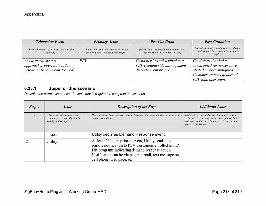
Appendix B
ZigBee+HomePlug Joint Working Group MRD Page 218 of 310
Triggering Event Primary Actor PreCondition PostCondition
(Identify the name of the event that start the
scenario)
(Identify the actor whose pointofview is
primarily used to describe the steps)
(Identify any preconditions or actor states
necessary for the scenario to start)
(Identify the postconditions or significant
results required to consider the scenario
complete)
As electrical system
approaches overload and/or
resources become constrained
PEV Customer has subscribed to a
PEV demand side management
discrete event program.
Conditions that led to
constrained resources have
abated or been mitigated.
Customer returns to normal
PEV load operation.
0.33.1 Steps for this scenarioDescribe the normal sequence of events that is required to complete the scenario.
Step # Actor Description of the Step Additional Notes
# What actor, either primary or
secondary is responsible for the
activity in this step?
Describe the actions that take place in this step. The step should be described in
active, present tense.
Elaborate on any additional description or value
of the step to help support the descriptions. Short
notes on architecture challenges, etc. may also be
noted in this column..
1 Utility Utility declares Demand Response event.
2 Utility At least 24 hours prior to event, Utility sends out remote notification to PEV Customers enrolled in PEV DR programs indicating demand response action. Notification can be via pager, email, text message on cell phone, web page, etc.
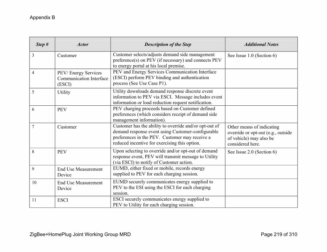
Appendix B
ZigBee+HomePlug Joint Working Group MRD Page 219 of 310
Step # Actor Description of the Step Additional Notes
3 Customer Customer selects/adjusts demand side management preference(s) on PEV (if necessary) and connects PEV to energy portal at his local premise.
See Issue 1.0 (Section 6)
4 PEV/ Energy Services Communication Interface (ESCI)
PEV and Energy Services Communication Interface (ESCI) perform PEV binding and authentication process (See Use Case P1).
5 Utility Utility downloads demand response discrete event information to PEV via ESCI. Message includes event information or load reduction request notification.
6 PEV PEV charging proceeds based on Customer defined preferences (which considers receipt of demand side management information).
7 Customer Customer has the ability to override and/or optout of demand response event using Customerconfigurable preferences in the PEV. Customer may receive a reduced incentive for exercising this option.
Other means of indicating override or optout (e.g., outside of vehicle) may also be considered here.
8 PEV Upon selecting to override and/or optout of demand response event, PEV will transmit message to Utility (via ESCI) to notify of Customer action.
See Issue 2.0 (Section 6)
9 End Use Measurement Device
EUMD, either fixed or mobile, records energy supplied to PEV for each charging session.
10 End Use Measurement Device
EUMD securely communicates energy supplied to PEV to the ESI using the ESCI for each charging session.
11 ESCI ESCI securely communicates energy supplied to PEV to Utility for each charging session.
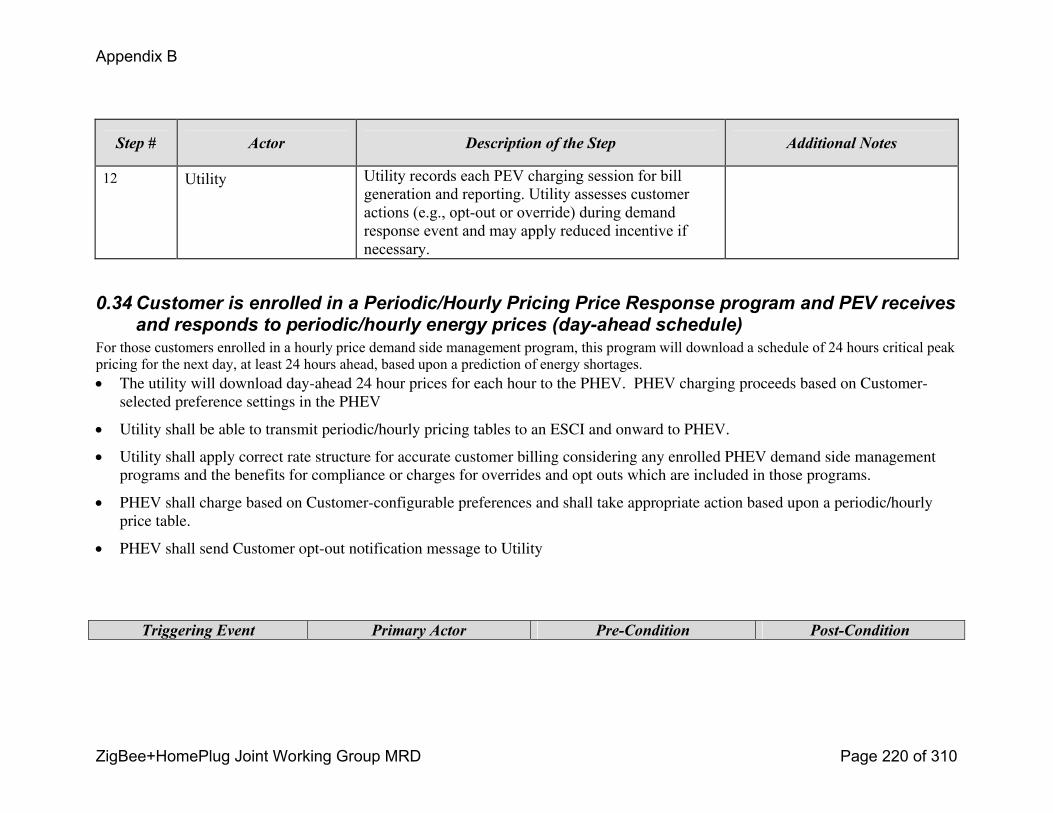
Appendix B
ZigBee+HomePlug Joint Working Group MRD Page 220 of 310
Step # Actor Description of the Step Additional Notes
12 Utility Utility records each PEV charging session for bill generation and reporting. Utility assesses customer actions (e.g., optout or override) during demand response event and may apply reduced incentive if necessary.
0.34 Customer is enrolled in a Periodic/Hourly Pricing Price Response program and PEV receives and responds to periodic/hourly energy prices (dayahead schedule)
For those customers enrolled in a hourly price demand side management program, this program will download a schedule of 24 hours critical peak pricing for the next day, at least 24 hours ahead, based upon a prediction of energy shortages. ! The utility will download day-ahead 24 hour prices for each hour to the PHEV. PHEV charging proceeds based on Customer-
selected preference settings in the PHEV
! Utility shall be able to transmit periodic/hourly pricing tables to an ESCI and onward to PHEV.
! Utility shall apply correct rate structure for accurate customer billing considering any enrolled PHEV demand side management programs and the benefits for compliance or charges for overrides and opt outs which are included in those programs.
! PHEV shall charge based on Customer-configurable preferences and shall take appropriate action based upon a periodic/hourly price table.
! PHEV shall send Customer opt-out notification message to Utility
Triggering Event Primary Actor PreCondition PostCondition
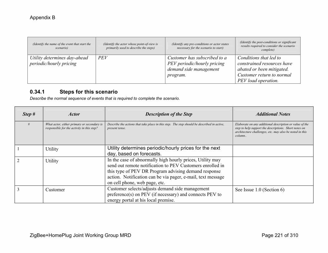
Appendix B
ZigBee+HomePlug Joint Working Group MRD Page 221 of 310
(Identify the name of the event that start the
scenario)
(Identify the actor whose pointofview is
primarily used to describe the steps)
(Identify any preconditions or actor states
necessary for the scenario to start)
(Identify the postconditions or significant
results required to consider the scenario
complete)
Utility determines dayahead
periodic/hourly pricing
PEV Customer has subscribed to a
PEV periodic/hourly pricing
demand side management
program.
Conditions that led to
constrained resources have
abated or been mitigated.
Customer return to normal
PEV load operation.
0.34.1 Steps for this scenarioDescribe the normal sequence of events that is required to complete the scenario.
Step # Actor Description of the Step Additional Notes
# What actor, either primary or secondary is
responsible for the activity in this step?
Describe the actions that take place in this step. The step should be described in active,
present tense.
Elaborate on any additional description or value of the
step to help support the descriptions. Short notes on
architecture challenges, etc. may also be noted in this
column..
1 Utility Utility determines periodic/hourly prices for the next day, based on forecasts.
2 Utility In the case of abnormally high hourly prices, Utility may send out remote notification to PEV Customers enrolled in this type of PEV DR Program advising demand response action. Notification can be via pager, email, text message on cell phone, web page, etc.
3 Customer Customer selects/adjusts demand side management preference(s) on PEV (if necessary) and connects PEV to energy portal at his local premise.
See Issue 1.0 (Section 6)
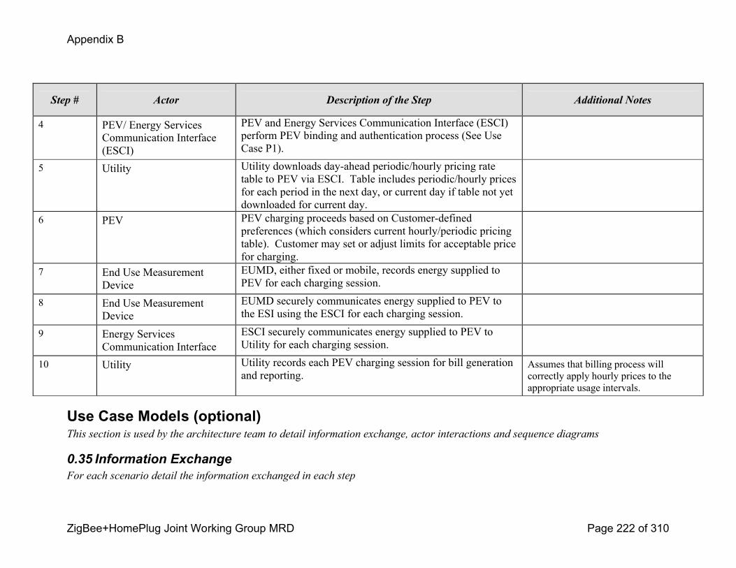
Appendix B
ZigBee+HomePlug Joint Working Group MRD Page 222 of 310
Step # Actor Description of the Step Additional Notes
4 PEV/ Energy Services Communication Interface (ESCI)
PEV and Energy Services Communication Interface (ESCI) perform PEV binding and authentication process (See Use Case P1).
5 Utility Utility downloads dayahead periodic/hourly pricing rate table to PEV via ESCI. Table includes periodic/hourly prices for each period in the next day, or current day if table not yet downloaded for current day.
6 PEV PEV charging proceeds based on Customerdefined preferences (which considers current hourly/periodic pricing table). Customer may set or adjust limits for acceptable price for charging.
7 End Use Measurement Device
EUMD, either fixed or mobile, records energy supplied to PEV for each charging session.
8 End Use Measurement Device
EUMD securely communicates energy supplied to PEV to the ESI using the ESCI for each charging session.
9 Energy Services Communication Interface
ESCI securely communicates energy supplied to PEV to Utility for each charging session.
10 Utility Utility records each PEV charging session for bill generation and reporting.
Assumes that billing process will correctly apply hourly prices to the appropriate usage intervals.
Use Case Models (optional)This section is used by the architecture team to detail information exchange, actor interactions and sequence diagrams
0.35 Information ExchangeFor each scenario detail the information exchanged in each step
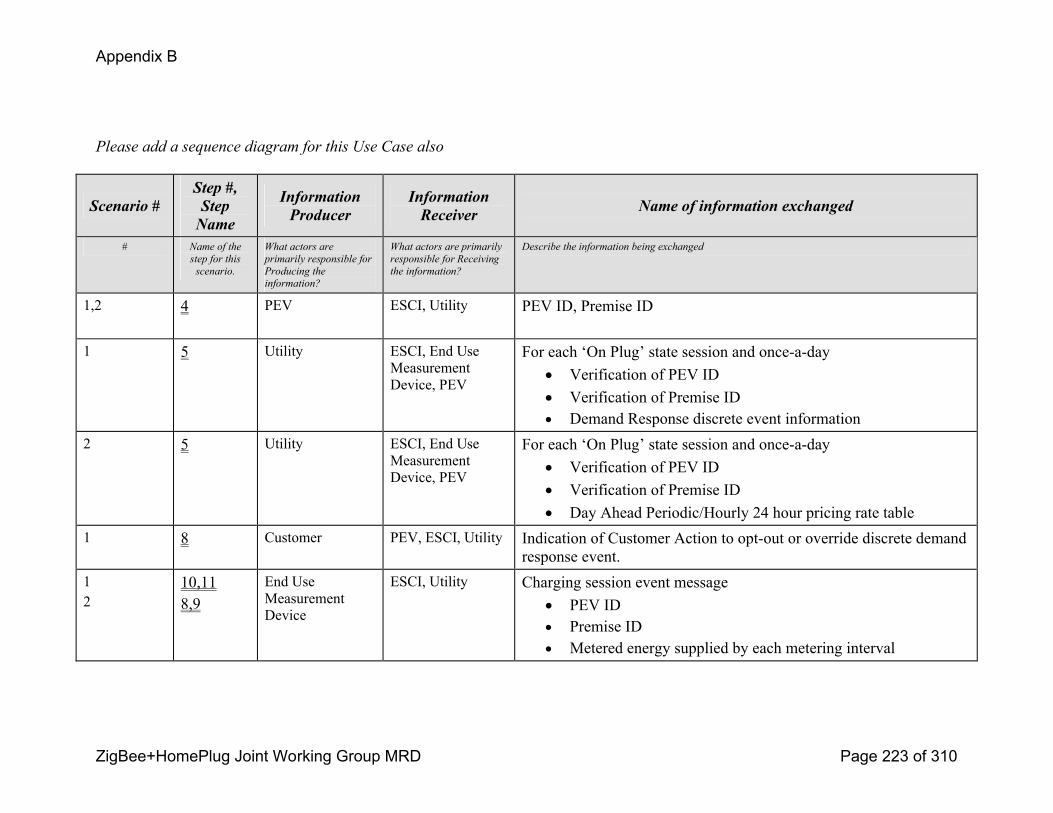
Appendix B
ZigBee+HomePlug Joint Working Group MRD Page 223 of 310
Please add a sequence diagram for this Use Case also
Scenario #Step #, Step Name
Information Producer
Information Receiver Name of information exchanged
# Name of the
step for this
scenario.
What actors are
primarily responsible for
Producing the
information?
What actors are primarily
responsible for Receiving
the information?
Describe the information being exchanged
1,2 4 PEV ESCI, Utility PEV ID, Premise ID
1 5 Utility ESCI, End Use Measurement Device, PEV
For each ‘On Plug’ state session and onceaday! Verification of PEV ID! Verification of Premise ID! Demand Response discrete event information
2 5 Utility ESCI, End Use Measurement Device, PEV
For each ‘On Plug’ state session and onceaday! Verification of PEV ID! Verification of Premise ID! Day Ahead Periodic/Hourly 24 hour pricing rate table
1 8 Customer PEV, ESCI, Utility Indication of Customer Action to optout or override discrete demand response event.
12
10,118,9
End Use Measurement Device
ESCI, Utility Charging session event message! PEV ID! Premise ID! Metered energy supplied by each metering interval

Appendix B
ZigBee+HomePlug Joint Working Group MRD Page 224 of 310
Use Case IssuesCapture any issues with the use case. Specifically, these are issues that are not resolved and help the use case reader understand the constraints or unresolved factors that have an impact of the use case scenarios and their realization.
Issue
Describe the issue as well as any potential impacts to the use case.
1.0 – Implied assumption with this step (in both scenarios) is that PEV operator must be at ‘home’ premise to receive Demand side management information (discrete events or hourly prices). Need to consider if this is truly a constraint or not. 2.0 – Unclear how confirmation of override is communicated back to the Utility, or if this is required (or not). There was discussion during the workshop about communicating PEV preference settings to the Utility upon change or upon each communications linkup.
GlossaryInsert the terms and definitions relevant to this use case. Please ensure that any glossary item added to this list should be included in
the global glossary to ensure consistency between use cases.
GlossaryTerm DefinitionRate tariff Energy cost schedule to customer. Can be timeofday, flat rate, seasonal rate, critical peak price rate, etc.PEV Plugin Electric VehicleEUMD End Use Measurement Device, revenue measuring deviceESCI Energy Services Communication InterfaceCharging Act of electrically charging a battery onboard a Plugin Electric Vehicle or Electric Vehicle
Appendix B
ZigBee+HomePlug Joint Working Group MRD Page 225 of 310
Load Control and Demand Response Use Case
Utility Initiates Demand Response
L_02: 2.2 – Scenario 1: Utility initiates a demand response event.
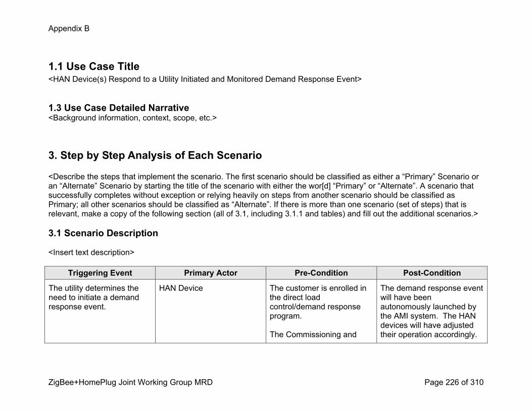
Appendix B
ZigBee+HomePlug Joint Working Group MRD Page 226 of 310
1.1 Use Case Title<HAN Device(s) Respond to a Utility Initiated and Monitored Demand Response Event>
1.3 Use Case Detailed Narrative<Background information, context, scope, etc.>
3. Step by Step Analysis of Each Scenario
<Describe the steps that implement the scenario. The first scenario should be classified as either a “Primary” Scenario or an “Alternate” Scenario by starting the title of the scenario with either the wor[d] “Primary” or “Alternate”. A scenario that successfully completes without exception or relying heavily on steps from another scenario should be classified as Primary; all other scenarios should be classified as “Alternate”. If there is more than one scenario (set of steps) that is relevant, make a copy of the following section (all of 3.1, including 3.1.1 and tables) and fill out the additional scenarios.>
3.1 Scenario Description
<Insert text description>
Triggering Event Primary Actor PreCondition PostCondition
The utility determines the need to initiate a demand response event.
HAN Device The customer is enrolled in the direct load control/demand response program.
The Commissioning and
The demand response event will have been autonomously launched by the AMI system. The HAN devices will have adjusted their operation accordingly.

Appendix B
ZigBee+HomePlug Joint Working Group MRD Page 227 of 310
Registration Use Cases have been successfully completed.
After the demand response event has ended, the consumers equipment is returned to its original state. Transaction logs & date will be made available to analyze.
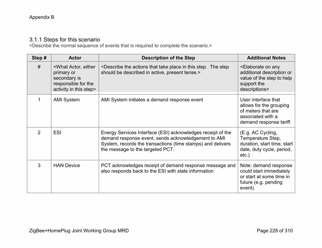
Appendix B
ZigBee+HomePlug Joint Working Group MRD Page 228 of 310
3.1.1 Steps for this scenario<Describe the normal sequence of events that is required to complete the scenario.>
Step # Actor Description of the Step Additional Notes
# <What Actor, either primary or secondary is responsible for the activity in this step>
<Describe the actions that take place in this step. The step should be described in active, present tense.>
<Elaborate on any additional description or value of the step to help support the descriptions>
1 AMI System AMI System initiates a demand response event User interface that allows for the grouping of meters that are associated with a demand response tariff.
2 ESI Energy Services Interface (ESI) acknowledges receipt of the demand response event, sends acknowledgement to AMI System, records the transactions (time stamps) and delivers the message to the targeted PCT.
(E.g. AC Cycling, Temperature Step, duration, start time, start date, duty cycle, period, etc.)
3 HAN Device PCT acknowledges receipt of demand response message and also responds back to the ESI with state information
Note: demand response could start immediately or start at some time in future (e.g. pending event).
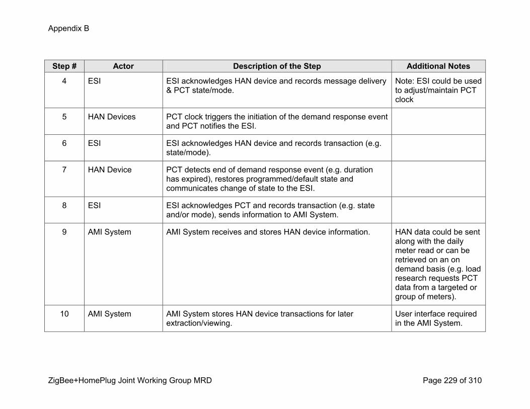
Appendix B
ZigBee+HomePlug Joint Working Group MRD Page 229 of 310
Step # Actor Description of the Step Additional Notes
4 ESI ESI acknowledges HAN device and records message delivery & PCT state/mode.
Note: ESI could be used to adjust/maintain PCT clock
5 HAN Devices PCT clock triggers the initiation of the demand response event and PCT notifies the ESI.
6 ESI ESI acknowledges HAN device and records transaction (e.g. state/mode).
7 HAN Device PCT detects end of demand response event (e.g. duration has expired), restores programmed/default state and communicates change of state to the ESI.
8 ESI ESI acknowledges PCT and records transaction (e.g. state and/or mode), sends information to AMI System.
9 AMI System AMI System receives and stores HAN device information. HAN data could be sent along with the daily meter read or can be retrieved on an on demand basis (e.g. load research requests PCT data from a targeted or group of meters).
10 AMI System AMI System stores HAN device transactions for later extraction/viewing.
User interface required in the AMI System.
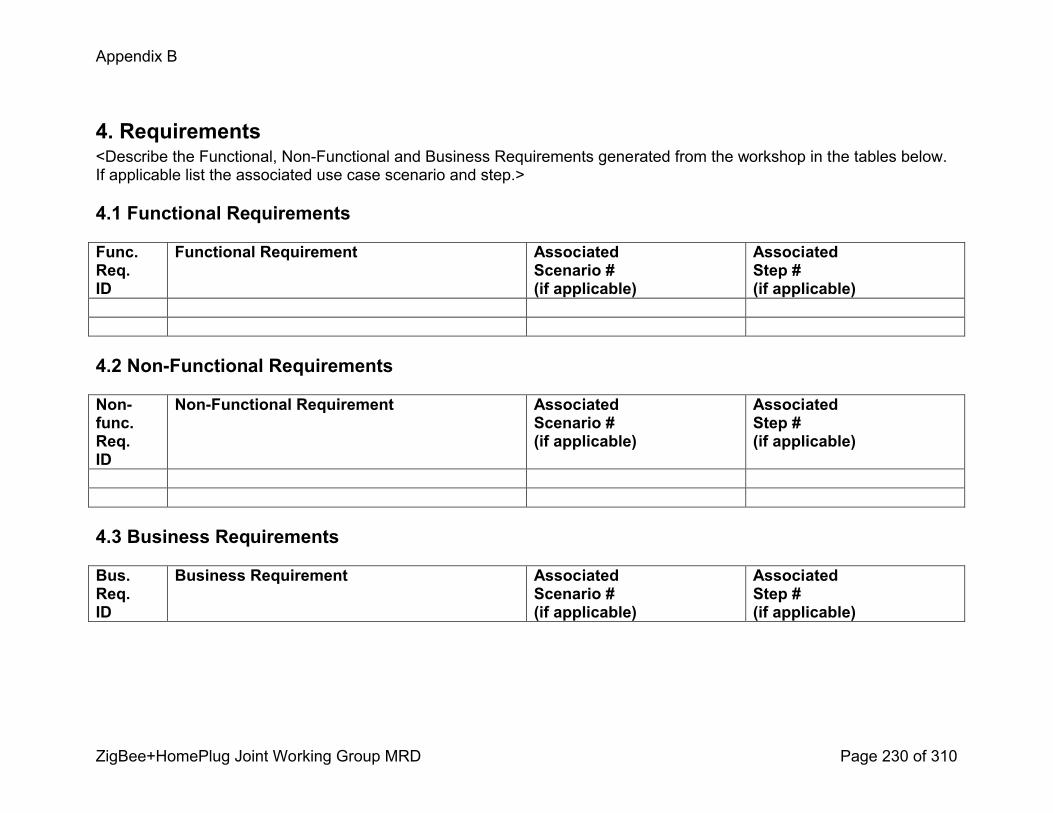
Appendix B
ZigBee+HomePlug Joint Working Group MRD Page 230 of 310
4. Requirements<Describe the Functional, NonFunctional and Business Requirements generated from the workshop in the tables below. If applicable list the associated use case scenario and step.>
4.1 Functional Requirements
Func.Req.ID
Functional Requirement AssociatedScenario #(if applicable)
AssociatedStep #(if applicable)
4.2 NonFunctional Requirements
Nonfunc.Req.ID
NonFunctional Requirement AssociatedScenario #(if applicable)
AssociatedStep #(if applicable)
4.3 Business Requirements
Bus.Req.ID
Business Requirement AssociatedScenario #(if applicable)
AssociatedStep #(if applicable)
Appendix B
ZigBee+HomePlug Joint Working Group MRD Page 231 of 310
Load Control and Demand Response Use Case
Utility Initiates Demand Response_02.1: 2.2 – Scenario 1: REP initiates a demand response event

Appendix B
ZigBee+HomePlug Joint Working Group MRD Page 232 of 310
1.1 Use Case Title<HAN Device(s) Respond to a Utility Initiated and Monitored Demand Response Event – ESI resolves HAN device error>
1.3 Use Case Detailed Narrative<Background information, context, scope, etc.>
3. Step by Step Analysis of Each Scenario
<Describe the steps that implement the scenario. The first scenario should be classified as either a “Primary” Scenario or an “Alternate” Scenario by starting the title of the scenario with either the wor[d] “Primary” or “Alternate”. A scenario that successfully completes without exception or relying heavily on steps from another scenario should be classified as Primary; all other scenarios should be classified as “Alternate”. If there is more than one scenario (set of steps) that is relevant, make a copy of the following section (all of 3.1, including 3.1.1 and tables) and fill out the additional scenarios.>
3.1 Scenario Description
<Insert text description>
Triggering Event Primary Actor PreCondition PostCondition
The utility determines the need to initiate a demand response event.
HAN Device The customer is enrolled in the direct load control/demand response program.
The Commissioning and
The demand response event will have been autonomously launched by the AMI system. The HAN devices will have adjusted their operation accordingly.
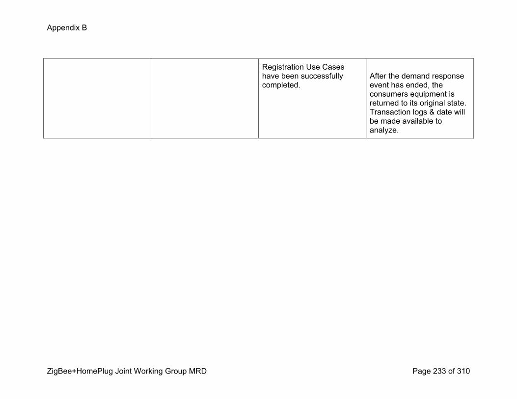
Appendix B
ZigBee+HomePlug Joint Working Group MRD Page 233 of 310
Registration Use Cases have been successfully completed.
After the demand response event has ended, the consumers equipment is returned to its original state. Transaction logs & date will be made available to analyze.
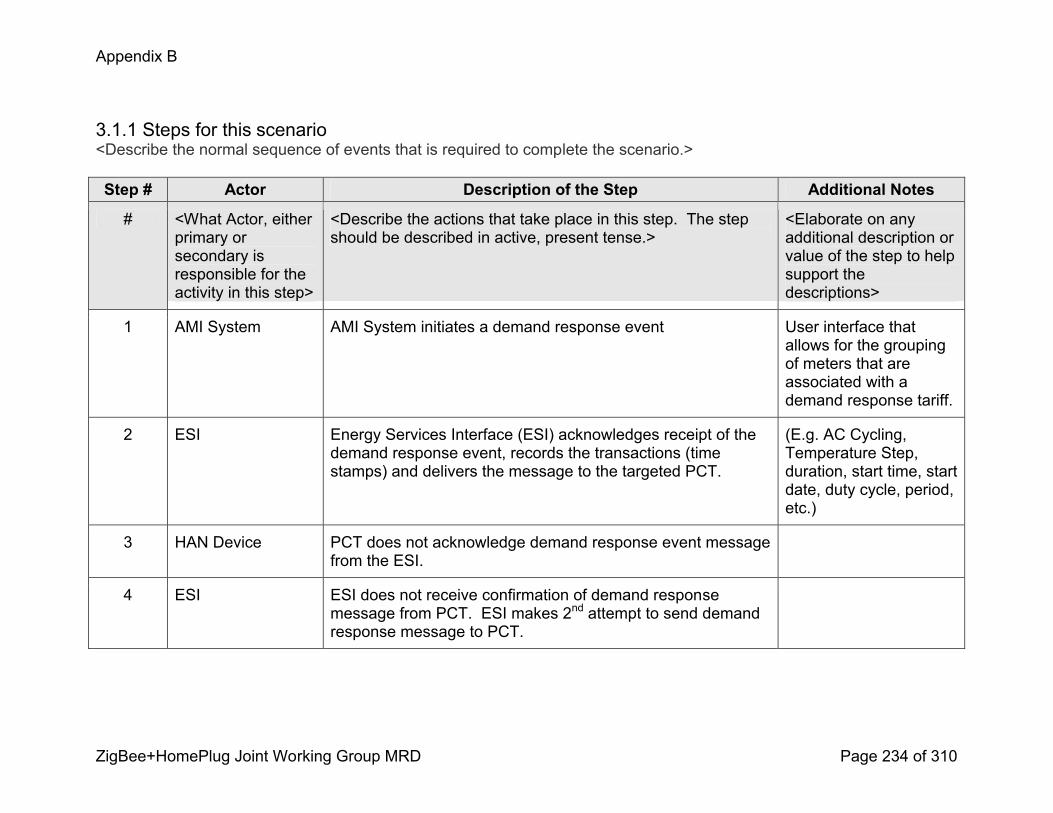
Appendix B
ZigBee+HomePlug Joint Working Group MRD Page 234 of 310
3.1.1 Steps for this scenario<Describe the normal sequence of events that is required to complete the scenario.>
Step # Actor Description of the Step Additional Notes
# <What Actor, either primary or secondary is responsible for the activity in this step>
<Describe the actions that take place in this step. The step should be described in active, present tense.>
<Elaborate on any additional description or value of the step to help support the descriptions>
1 AMI System AMI System initiates a demand response event User interface that allows for the grouping of meters that are associated with a demand response tariff.
2 ESI Energy Services Interface (ESI) acknowledges receipt of the demand response event, records the transactions (time stamps) and delivers the message to the targeted PCT.
(E.g. AC Cycling, Temperature Step, duration, start time, start date, duty cycle, period, etc.)
3 HAN Device PCT does not acknowledge demand response event message from the ESI.
4 ESI ESI does not receive confirmation of demand response message from PCT. ESI makes 2nd attempt to send demand response message to PCT.
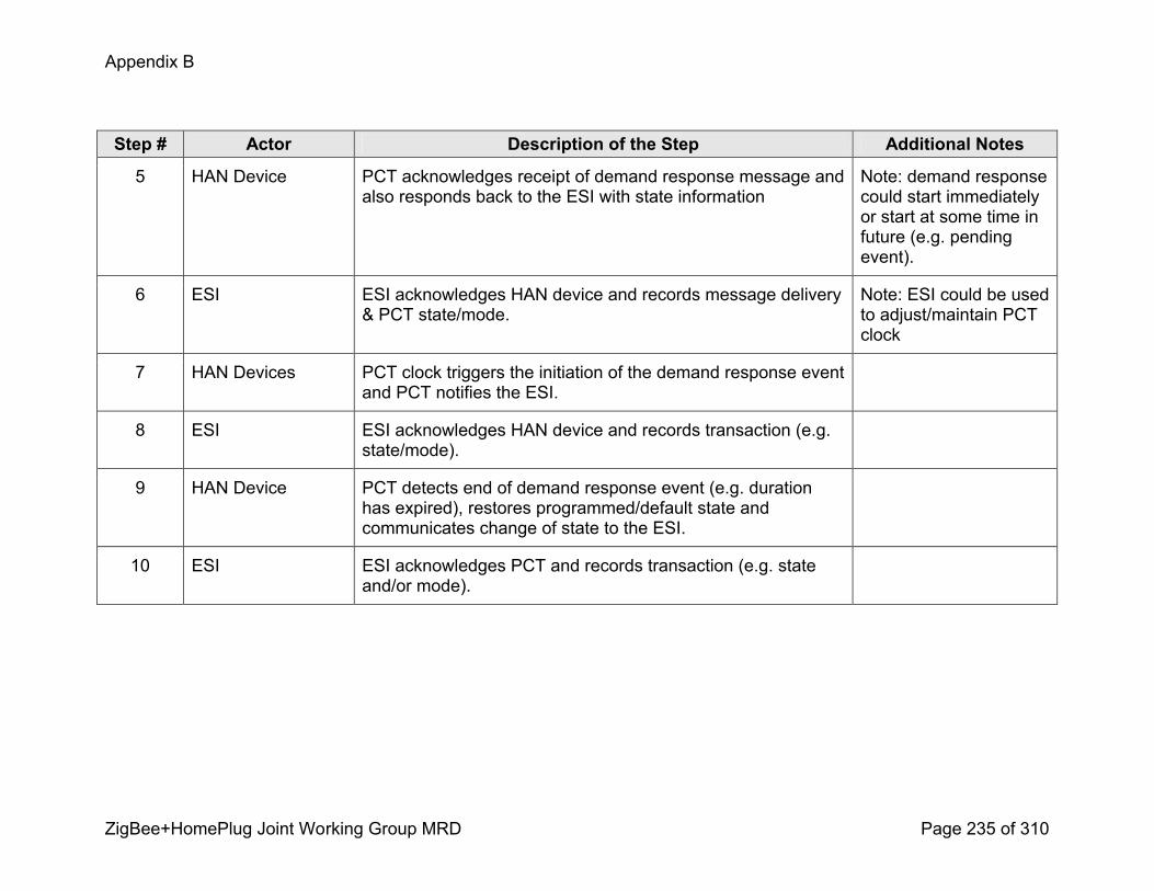
Appendix B
ZigBee+HomePlug Joint Working Group MRD Page 235 of 310
Step # Actor Description of the Step Additional Notes
5 HAN Device PCT acknowledges receipt of demand response message and also responds back to the ESI with state information
Note: demand response could start immediately or start at some time in future (e.g. pending event).
6 ESI ESI acknowledges HAN device and records message delivery & PCT state/mode.
Note: ESI could be used to adjust/maintain PCT clock
7 HAN Devices PCT clock triggers the initiation of the demand response event and PCT notifies the ESI.
8 ESI ESI acknowledges HAN device and records transaction (e.g. state/mode).
9 HAN Device PCT detects end of demand response event (e.g. duration has expired), restores programmed/default state and communicates change of state to the ESI.
10 ESI ESI acknowledges PCT and records transaction (e.g. state and/or mode).

Appendix B
ZigBee+HomePlug Joint Working Group MRD Page 236 of 310
Step # Actor Description of the Step Additional Notes
11 AMI System AMI System receives and stores HAN device information. HAN data could be sent along with the daily meter read or can be retrieved on an on demand basis (e.g. load research requests PCT data from a targeted or group of meters).
10 AMI System AMI System stores HAN device transactions for later extraction/viewing.
User interface required in the AMI System.

Appendix B
ZigBee+HomePlug Joint Working Group MRD Page 237 of 310
4. Requirements<Describe the Functional, NonFunctional and Business Requirements generated from the workshop in the tables below. If applicable list the associated use case scenario and step.>
4.1 Functional Requirements
Func.Req.ID
Functional Requirement AssociatedScenario #(if applicable)
AssociatedStep #(if applicable)
4.2 NonFunctional Requirements
Nonfunc.Req.ID
NonFunctional Requirement AssociatedScenario #(if applicable)
AssociatedStep #(if applicable)
4.3 Business Requirements
Bus.Req.ID
Business Requirement AssociatedScenario #(if applicable)
AssociatedStep #(if applicable)
Appendix B
ZigBee+HomePlug Joint Working Group MRD Page 238 of 310
Load Control and Demand Response Use Case
Utility Initiates Demand ResponseL_07: 2.2 – Scenario 6: Subordinate of L_02: Utility initiates a demand response event. The PCT fails to respond.
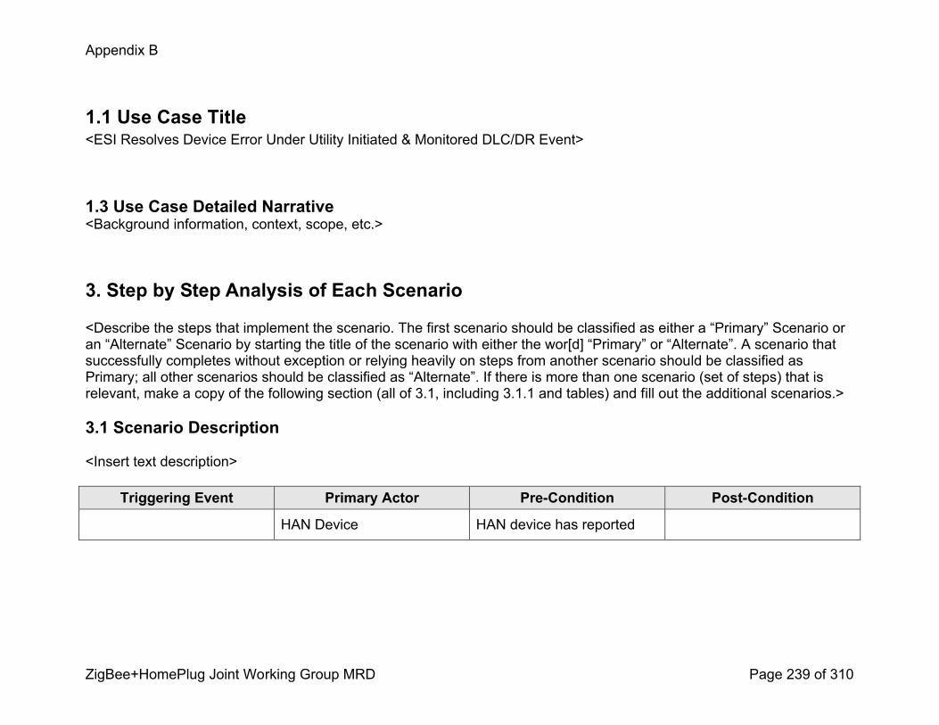
Appendix B
ZigBee+HomePlug Joint Working Group MRD Page 239 of 310
1.1 Use Case Title<ESI Resolves Device Error Under Utility Initiated & Monitored DLC/DR Event>
1.3 Use Case Detailed Narrative<Background information, context, scope, etc.>
3. Step by Step Analysis of Each Scenario
<Describe the steps that implement the scenario. The first scenario should be classified as either a “Primary” Scenario or an “Alternate” Scenario by starting the title of the scenario with either the wor[d] “Primary” or “Alternate”. A scenario that successfully completes without exception or relying heavily on steps from another scenario should be classified as Primary; all other scenarios should be classified as “Alternate”. If there is more than one scenario (set of steps) that is relevant, make a copy of the following section (all of 3.1, including 3.1.1 and tables) and fill out the additional scenarios.>
3.1 Scenario Description
<Insert text description>
Triggering Event Primary Actor PreCondition PostCondition
HAN Device HAN device has reported
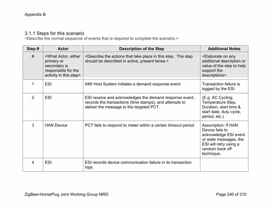
Appendix B
ZigBee+HomePlug Joint Working Group MRD Page 240 of 310
3.1.1 Steps for this scenario<Describe the normal sequence of events that is required to complete the scenario.>
Step # Actor Description of the Step Additional Notes
# <What Actor, either primary or secondary is responsible for the activity in this step>
<Describe the actions that take place in this step. The step should be described in active, present tense.>
<Elaborate on any additional description or value of the step to help support the descriptions>
1 ESI AMI Host System initiates a demand response event Transaction failure is logged by the ESI
2 ESI ESI receive and acknowledges the demand response event, records the transactions (time stamps), and attempts to deliver the message to the targeted PCT.
(E.g. AC Cycling, Temperature Step, Duration, start time & start date, duty cycle, period, etc.)
3 HAN Device PCT fails to respond to meter within a certain timeout period Assumption: If HAN Device fails to acknowledge ESI event or state messages, the ESI will retry using a random back off technique.
4 ESI ESI records device communication failure in its transaction logs.

Appendix B
ZigBee+HomePlug Joint Working Group MRD Page 241 of 310
4. Requirements<Describe the Functional, NonFunctional and Business Requirements generated from the workshop in the tables below. If applicable list the associated use case scenario and step.>
4.1 Functional Requirements
Func.Req.ID
Functional Requirement AssociatedScenario #(if applicable)
AssociatedStep #(if applicable)
4.2 NonFunctional Requirements
Nonfunc.Req.ID
NonFunctional Requirement AssociatedScenario #(if applicable)
AssociatedStep #(if applicable)
4.3 Business Requirements
Bus.Req.ID
Business Requirement AssociatedScenario #(if applicable)
AssociatedStep #(if applicable)
Appendix B
ZigBee+HomePlug Joint Working Group MRD Page 242 of 310
Load Control and Demand Response Use Case
Utility Initiates Demand ResponseREP Sends a Load Control Event Request
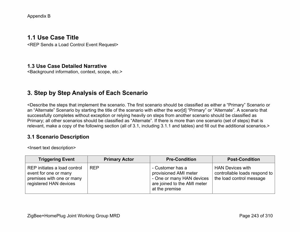
Appendix B
ZigBee+HomePlug Joint Working Group MRD Page 243 of 310
1.1 Use Case Title<REP Sends a Load Control Event Request>
1.3 Use Case Detailed Narrative<Background information, context, scope, etc.>
3. Step by Step Analysis of Each Scenario
<Describe the steps that implement the scenario. The first scenario should be classified as either a “Primary” Scenario or an “Alternate” Scenario by starting the title of the scenario with either the wor[d] “Primary” or “Alternate”. A scenario that successfully completes without exception or relying heavily on steps from another scenario should be classified as Primary; all other scenarios should be classified as “Alternate”. If there is more than one scenario (set of steps) that is relevant, make a copy of the following section (all of 3.1, including 3.1.1 and tables) and fill out the additional scenarios.>
3.1 Scenario Description
<Insert text description>
Triggering Event Primary Actor PreCondition PostCondition
REP initiates a load control event for one or many premises with one or many registered HAN devices
REP Customer has a provisioned AMI meter One or many HAN devices are joined to the AMI meter at the premise
HAN Devices with controllable loads respond to the load control message
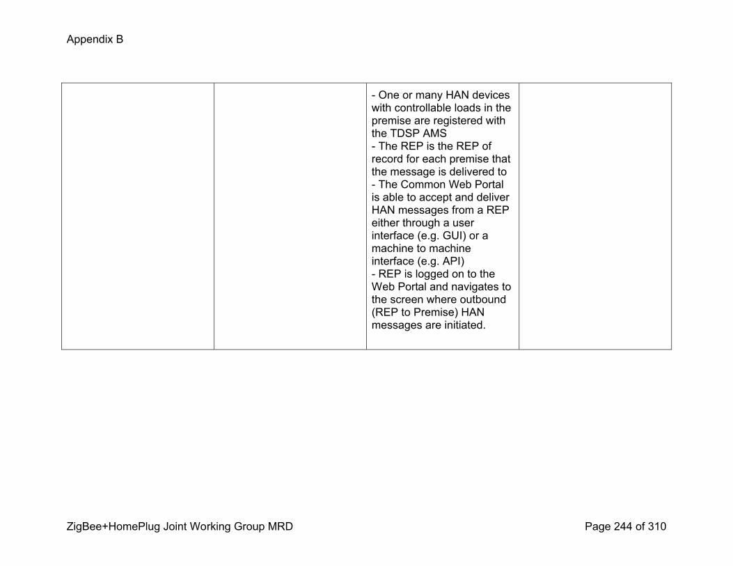
Appendix B
ZigBee+HomePlug Joint Working Group MRD Page 244 of 310
One or many HAN devices with controllable loads in the premise are registered with the TDSP AMS The REP is the REP of record for each premise that the message is delivered to The Common Web Portal is able to accept and deliver HAN messages from a REP either through a user interface (e.g. GUI) or a machine to machine interface (e.g. API) REP is logged on to the Web Portal and navigates to the screen where outbound (REP to Premise) HAN messages are initiated.
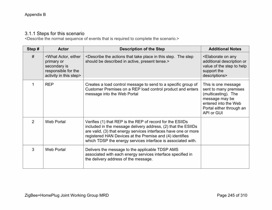
Appendix B
ZigBee+HomePlug Joint Working Group MRD Page 245 of 310
3.1.1 Steps for this scenario<Describe the normal sequence of events that is required to complete the scenario.>
Step # Actor Description of the Step Additional Notes
# <What Actor, either primary or secondary is responsible for the activity in this step>
<Describe the actions that take place in this step. The step should be described in active, present tense.>
<Elaborate on any additional description or value of the step to help support the descriptions>
1 REP Creates a load control message to send to a specific group of Customer Premises on a REP load control product and enters message into the Web Portal
This is one message sent to many premises (multicasting). The message may be entered into the Web Portal either through an API or GUI
2 Web Portal Verifies (1) that REP is the REP of record for the ESIIDs included in the message delivery address, (2) that the ESIIDs are valid, (3) that energy services interfaces have one or more registered HAN Devices at the Premise and (4) identifies which TDSP the energy services interface is associated with.
3 Web Portal Delivers the message to the applicable TDSP AMS associated with each energy services interface specified in the delivery address of the message.
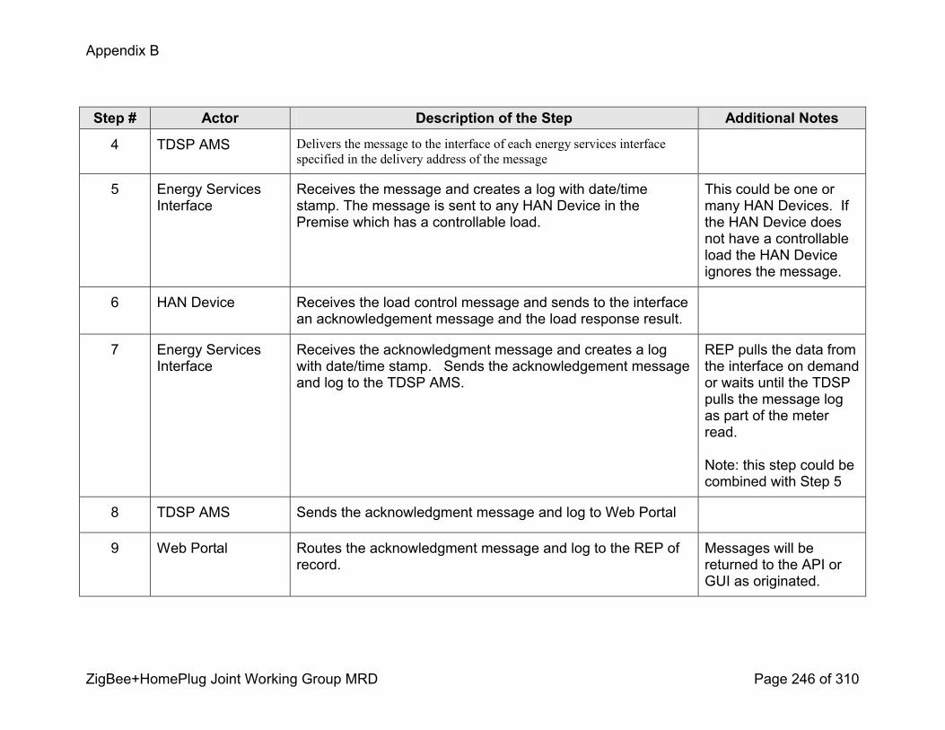
Appendix B
ZigBee+HomePlug Joint Working Group MRD Page 246 of 310
Step # Actor Description of the Step Additional Notes
4 TDSP AMS Delivers the message to the interface of each energy services interface specified in the delivery address of the message
5 Energy Services Interface
Receives the message and creates a log with date/time stamp. The message is sent to any HAN Device in the Premise which has a controllable load.
This could be one or many HAN Devices. If the HAN Device does not have a controllable load the HAN Device ignores the message.
6 HAN Device Receives the load control message and sends to the interface an acknowledgement message and the load response result.
7 Energy Services Interface
Receives the acknowledgment message and creates a log with date/time stamp. Sends the acknowledgement message and log to the TDSP AMS.
REP pulls the data from the interface on demand or waits until the TDSP pulls the message log as part of the meter read.
Note: this step could be combined with Step 5
8 TDSP AMS Sends the acknowledgment message and log to Web Portal
9 Web Portal Routes the acknowledgment message and log to the REP of record.
Messages will be returned to the API or GUI as originated.
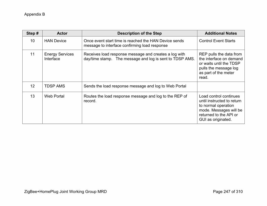
Appendix B
ZigBee+HomePlug Joint Working Group MRD Page 247 of 310
Step # Actor Description of the Step Additional Notes
10 HAN Device Once event start time is reached the HAN Device sends message to interface confirming load response
Control Event Starts
11 Energy Services Interface
Receives load response message and creates a log with day/time stamp. The message and log is sent to TDSP AMS.
REP pulls the data from the interface on demand or waits until the TDSP pulls the message log as part of the meter read.
12 TDSP AMS Sends the load response message and log to Web Portal
13 Web Portal Routes the load response message and log to the REP of record.
Load control continues until instructed to return to normal operation mode. Messages will be returned to the API or GUI as originated.

Appendix B
ZigBee+HomePlug Joint Working Group MRD Page 248 of 310
4. Requirements<Describe the Functional, NonFunctional and Business Requirements generated from the workshop in the tables below. If applicable list the associated use case scenario and step.>
4.1 Functional Requirements
Func.Req.ID
Functional Requirement AssociatedScenario #(if applicable)
AssociatedStep #(if applicable)
4.2 NonFunctional Requirements
Nonfunc.Req.ID
NonFunctional Requirement AssociatedScenario #(if applicable)
AssociatedStep #(if applicable)
4.3 Business Requirements
Bus.Req.ID
Business Requirement AssociatedScenario #(if applicable)
AssociatedStep #(if applicable)
Appendix B
ZigBee+HomePlug Joint Working Group MRD Page 249 of 310
Load Control and Demand Response Use Case
Utility Initiates Demand ResponseL_09 – Scenario 1: REP initiates a demand response event
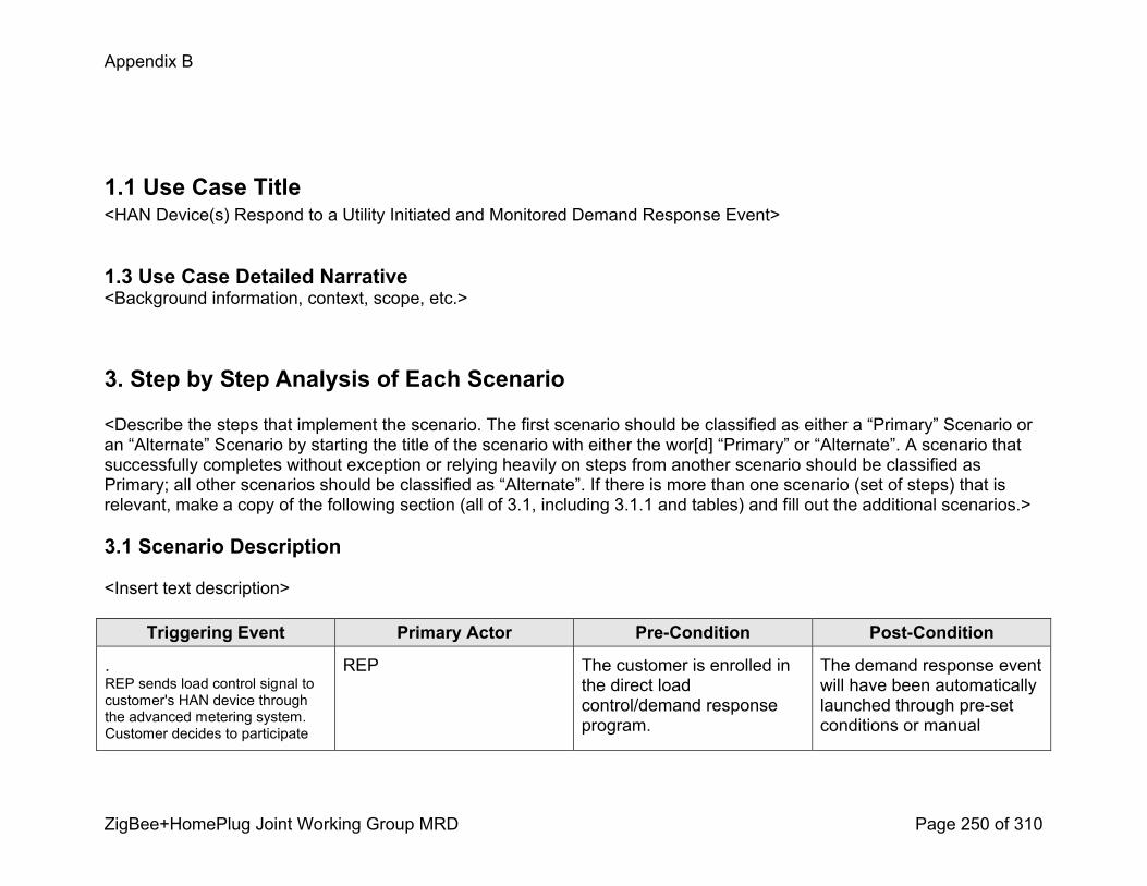
Appendix B
ZigBee+HomePlug Joint Working Group MRD Page 250 of 310
1.1 Use Case Title<HAN Device(s) Respond to a Utility Initiated and Monitored Demand Response Event>
1.3 Use Case Detailed Narrative<Background information, context, scope, etc.>
3. Step by Step Analysis of Each Scenario
<Describe the steps that implement the scenario. The first scenario should be classified as either a “Primary” Scenario or an “Alternate” Scenario by starting the title of the scenario with either the wor[d] “Primary” or “Alternate”. A scenario that successfully completes without exception or relying heavily on steps from another scenario should be classified as Primary; all other scenarios should be classified as “Alternate”. If there is more than one scenario (set of steps) that is relevant, make a copy of the following section (all of 3.1, including 3.1.1 and tables) and fill out the additional scenarios.>
3.1 Scenario Description
<Insert text description>
Triggering Event Primary Actor PreCondition PostCondition
.REP sends load control signal to customer's HAN device through the advanced metering system. Customer decides to participate
REP The customer is enrolled in the direct load control/demand response program.
The demand response event will have been automatically launched through preset conditions or manual

Appendix B
ZigBee+HomePlug Joint Working Group MRD Page 251 of 310
either through actions or preset device features. Confirmation is sent to the REP regarding the action taken.
.customer participation.
Load/event information sent to the REP
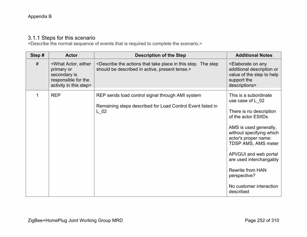
Appendix B
ZigBee+HomePlug Joint Working Group MRD Page 252 of 310
3.1.1 Steps for this scenario<Describe the normal sequence of events that is required to complete the scenario.>
Step # Actor Description of the Step Additional Notes
# <What Actor, either primary or secondary is responsible for the activity in this step>
<Describe the actions that take place in this step. The step should be described in active, present tense.>
<Elaborate on any additional description or value of the step to help support the descriptions>
1 REP REP sends load control signal through AMI system
Remaining steps described for Load Control Event listed in L_02
This is a subordinate use case of L_02
There is no description of the actor ESIIDs
AMS is used generally, without specifying which actor's proper name: TDSP AMS, AMS meter
API/GUI and web portal are used interchangably
Rewrite from HAN perspective?
No customer interaction described

Appendix B
ZigBee+HomePlug Joint Working Group MRD Page 253 of 310
Step # Actor Description of the Step Additional Notes
2 TDSP Don’t know what this is referring to
3 API/GUI Control Event sent through REP API to access AMI system Assuming this is talking about the API specific to the REP
4 Web Portal Event sent to Web Portal that allows customer to view/participate manually in event, if preset conditions do not exist or not desirable.
5 HAN Device HAN Device responds to event
6 Customer Customer presented with event information and either allows preset conditions to occur, or optout/adjust participation

Appendix B
ZigBee+HomePlug Joint Working Group MRD Page 254 of 310
4. Requirements<Describe the Functional, NonFunctional and Business Requirements generated from the workshop in the tables below. If applicable list the associated use case scenario and step.>
4.1 Functional Requirements
Func.Req.ID
Functional Requirement AssociatedScenario #(if applicable)
AssociatedStep #(if applicable)
4.2 NonFunctional Requirements
Nonfunc.Req.ID
NonFunctional Requirement AssociatedScenario #(if applicable)
AssociatedStep #(if applicable)
4.3 Business Requirements
Bus.Req.ID
Business Requirement AssociatedScenario #(if applicable)
AssociatedStep #(if applicable)

Appendix B
ZigBee+HomePlug Joint Working Group MRD Page 255 of 310
Load Control and Demand Response Use Case
Utility Initiates Demand ResponseL_10 – Scenario 1: REP initiates a demand response event
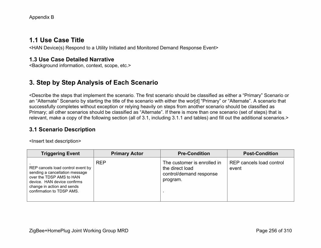
Appendix B
ZigBee+HomePlug Joint Working Group MRD Page 256 of 310
1.1 Use Case Title<HAN Device(s) Respond to a Utility Initiated and Monitored Demand Response Event>
1.3 Use Case Detailed Narrative<Background information, context, scope, etc.>
3. Step by Step Analysis of Each Scenario
<Describe the steps that implement the scenario. The first scenario should be classified as either a “Primary” Scenario or an “Alternate” Scenario by starting the title of the scenario with either the wor[d] “Primary” or “Alternate”. A scenario that successfully completes without exception or relying heavily on steps from another scenario should be classified as Primary; all other scenarios should be classified as “Alternate”. If there is more than one scenario (set of steps) that is relevant, make a copy of the following section (all of 3.1, including 3.1.1 and tables) and fill out the additional scenarios.>
3.1 Scenario Description
<Insert text description>
Triggering Event Primary Actor PreCondition PostCondition
.REP cancels load control event by sending a cancellation message over the TDSP AMS to HAN device. HAN device confirms change in action and sends confirmation to TDSP AMS.
REP The customer is enrolled in the direct load control/demand response program.
.
REP cancels load control event
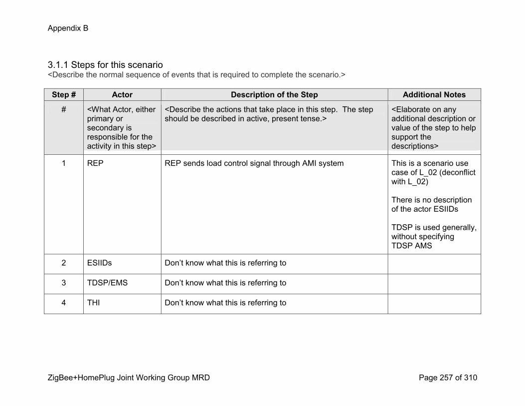
Appendix B
ZigBee+HomePlug Joint Working Group MRD Page 257 of 310
3.1.1 Steps for this scenario<Describe the normal sequence of events that is required to complete the scenario.>
Step # Actor Description of the Step Additional Notes
# <What Actor, either primary or secondary is responsible for the activity in this step>
<Describe the actions that take place in this step. The step should be described in active, present tense.>
<Elaborate on any additional description or value of the step to help support the descriptions>
1 REP REP sends load control signal through AMI system This is a scenario use case of L_02 (deconflict with L_02)
There is no description of the actor ESIIDs
TDSP is used generally, without specifying TDSP AMS
2 ESIIDs Don’t know what this is referring to
3 TDSP/EMS Don’t know what this is referring to
4 THI Don’t know what this is referring to
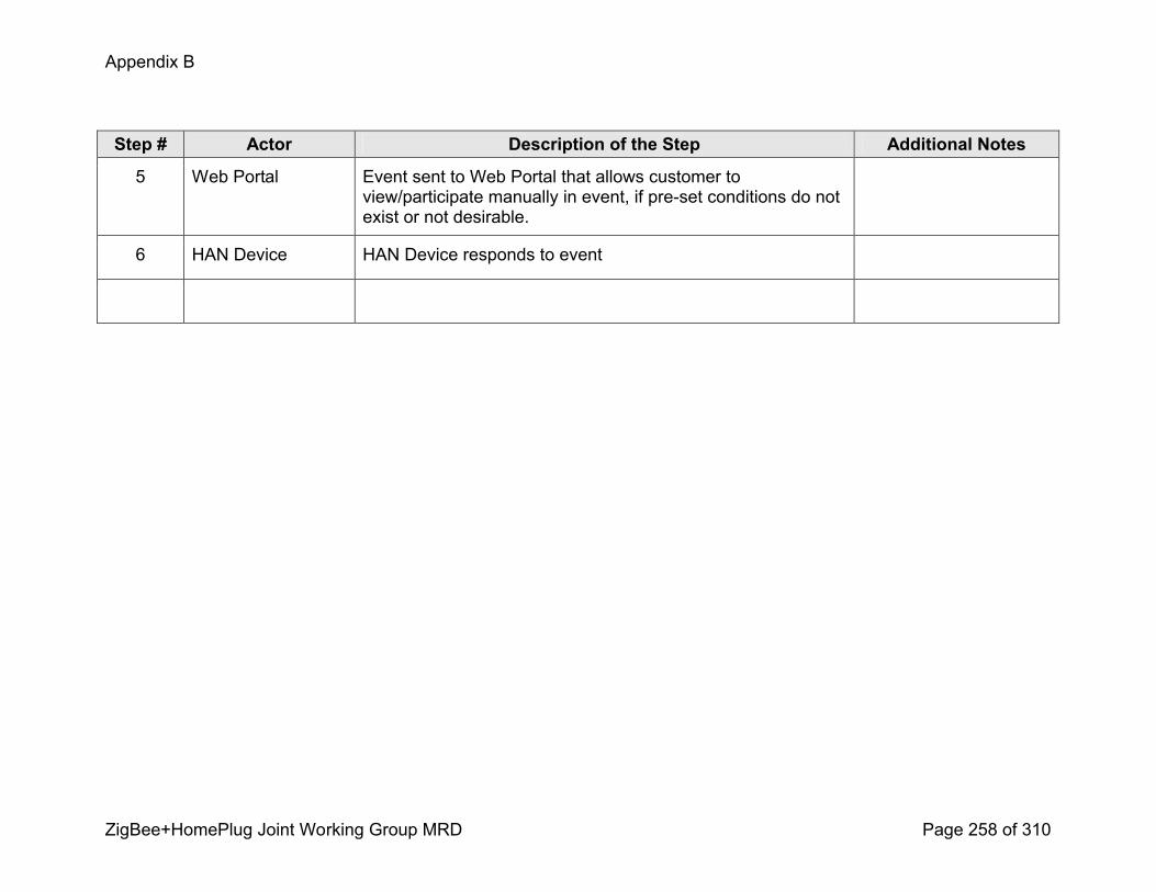
Appendix B
ZigBee+HomePlug Joint Working Group MRD Page 258 of 310
Step # Actor Description of the Step Additional Notes
5 Web Portal Event sent to Web Portal that allows customer to view/participate manually in event, if preset conditions do not exist or not desirable.
6 HAN Device HAN Device responds to event

Appendix B
ZigBee+HomePlug Joint Working Group MRD Page 259 of 310
4. Requirements<Describe the Functional, NonFunctional and Business Requirements generated from the workshop in the tables below. If applicable list the associated use case scenario and step.>
4.1 Functional Requirements
Func.Req.ID
Functional Requirement AssociatedScenario #(if applicable)
AssociatedStep #(if applicable)
4.2 NonFunctional Requirements
Nonfunc.Req.ID
NonFunctional Requirement AssociatedScenario #(if applicable)
AssociatedStep #(if applicable)
4.3 Business Requirements
Bus.Req.ID
Business Requirement AssociatedScenario #(if applicable)
AssociatedStep #(if applicable)
Appendix B
ZigBee+HomePlug Joint Working Group MRD Page 260 of 310
Load Control and Demand Response Use Case
Utility Initiates Demand Response
HAN Device(s) Respond to a Utility Initiated and Monitored Demand Response Event
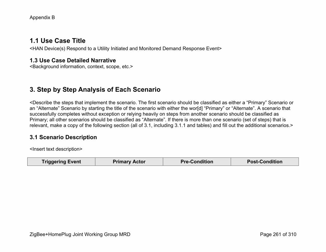
Appendix B
ZigBee+HomePlug Joint Working Group MRD Page 261 of 310
1.1 Use Case Title<HAN Device(s) Respond to a Utility Initiated and Monitored Demand Response Event>
1.3 Use Case Detailed Narrative<Background information, context, scope, etc.>
3. Step by Step Analysis of Each Scenario
<Describe the steps that implement the scenario. The first scenario should be classified as either a “Primary” Scenario or an “Alternate” Scenario by starting the title of the scenario with either the wor[d] “Primary” or “Alternate”. A scenario that successfully completes without exception or relying heavily on steps from another scenario should be classified as Primary; all other scenarios should be classified as “Alternate”. If there is more than one scenario (set of steps) that is relevant, make a copy of the following section (all of 3.1, including 3.1.1 and tables) and fill out the additional scenarios.>
3.1 Scenario Description
<Insert text description>
Triggering Event Primary Actor PreCondition PostCondition
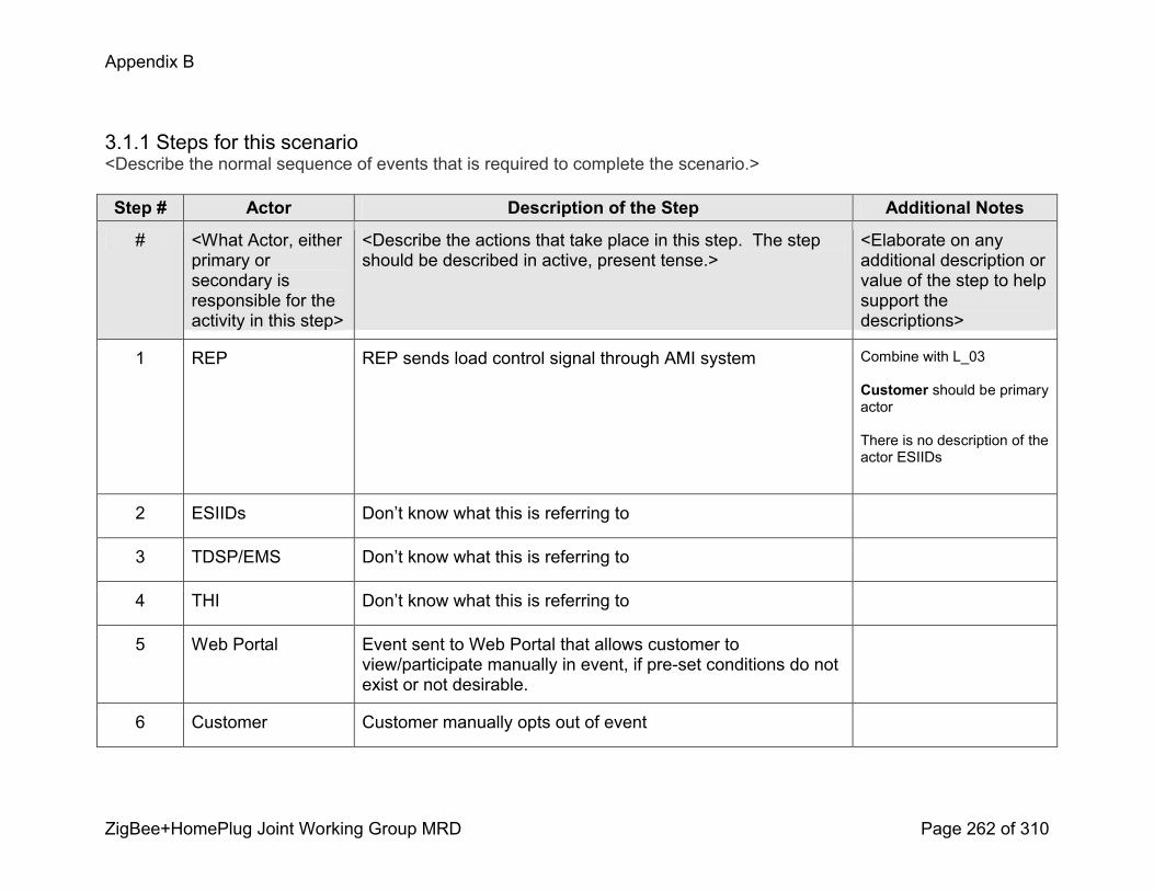
Appendix B
ZigBee+HomePlug Joint Working Group MRD Page 262 of 310
3.1.1 Steps for this scenario<Describe the normal sequence of events that is required to complete the scenario.>
Step # Actor Description of the Step Additional Notes
# <What Actor, either primary or secondary is responsible for the activity in this step>
<Describe the actions that take place in this step. The step should be described in active, present tense.>
<Elaborate on any additional description or value of the step to help support the descriptions>
1 REP REP sends load control signal through AMI system Combine with L_03
Customer should be primary actor
There is no description of the actor ESIIDs
2 ESIIDs Don’t know what this is referring to
3 TDSP/EMS Don’t know what this is referring to
4 THI Don’t know what this is referring to
5 Web Portal Event sent to Web Portal that allows customer to view/participate manually in event, if preset conditions do not exist or not desirable.
6 Customer Customer manually opts out of event
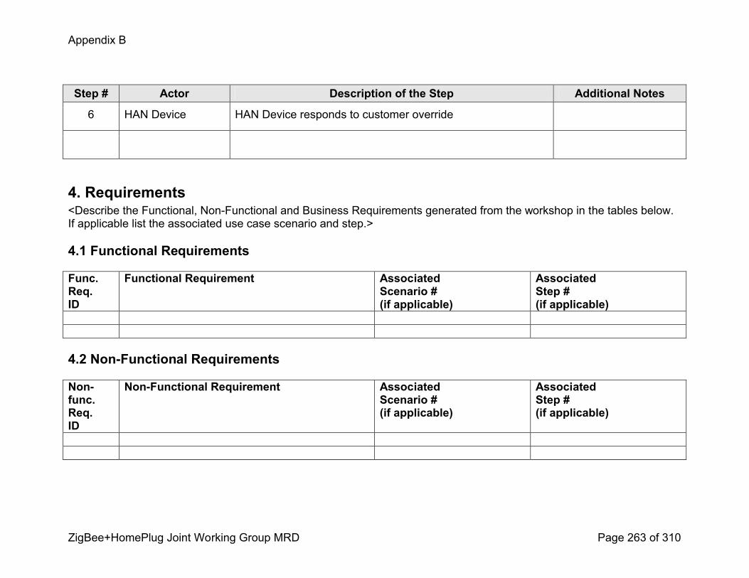
Appendix B
ZigBee+HomePlug Joint Working Group MRD Page 263 of 310
Step # Actor Description of the Step Additional Notes
6 HAN Device HAN Device responds to customer override
4. Requirements<Describe the Functional, NonFunctional and Business Requirements generated from the workshop in the tables below. If applicable list the associated use case scenario and step.>
4.1 Functional Requirements
Func.Req.ID
Functional Requirement AssociatedScenario #(if applicable)
AssociatedStep #(if applicable)
4.2 NonFunctional Requirements
Nonfunc.Req.ID
NonFunctional Requirement AssociatedScenario #(if applicable)
AssociatedStep #(if applicable)

Appendix B
ZigBee+HomePlug Joint Working Group MRD Page 264 of 310
4.3 Business Requirements
Bus.Req.ID
Business Requirement AssociatedScenario #(if applicable)
AssociatedStep #(if applicable)
Appendix B
ZigBee+HomePlug Joint Working Group MRD Page 265 of 310
Load Control and Demand Response Use Case
Utility Initiates Demand Response
HAN Device(s) Respond to a Utility Initiated and Monitored Demand Response Event

Appendix B
ZigBee+HomePlug Joint Working Group MRD Page 266 of 310
1.1 Use Case Title<HAN Device(s) Respond to a Utility Initiated and Monitored Demand Response Event>
1.3 Use Case Detailed Narrative<Background information, context, scope, etc.>
3. Step by Step Analysis of Each Scenario
<Describe the steps that implement the scenario. The first scenario should be classified as either a “Primary” Scenario or an “Alternate” Scenario by starting the title of the scenario with either the wor[d] “Primary” or “Alternate”. A scenario that successfully completes without exception or relying heavily on steps from another scenario should be classified as Primary; all other scenarios should be classified as “Alternate”. If there is more than one scenario (set of steps) that is relevant, make a copy of the following section (all of 3.1, including 3.1.1 and tables) and fill out the additional scenarios.>

Appendix B
ZigBee+HomePlug Joint Working Group MRD Page 267 of 310
3.1 Scenario Description
<Insert text description>
Triggering Event Primary Actor PreCondition PostConditionCustomer signs up for a voluntary demand response program with the utility. The utility sends a load control message, the message is logged by the customer's meter and load control devices in the premise curtail depending on the preset settings set by the customer or the utility. The customer has the ability to override. At the completion of the event, a message is sent from the utility and the customer's meter logs the completiion of the event.
REP The customer is enrolled in the direct load control/demand response program.
.
Event happens as it should, either automatically, or doesn’t happen due to customer optout
Redundant and covered in L_02 and L_03
Perhaps should be covered in messaging?

Appendix B
ZigBee+HomePlug Joint Working Group MRD Page 268 of 310
3.1.1 Steps for this scenario<Describe the normal sequence of events that is required to complete the scenario.>
Step # Actor Description of the Step Additional Notes
# <What Actor, either primary or secondary is responsible for the activity in this step>
<Describe the actions that take place in this step. The step should be described in active, present tense.>
<Elaborate on any additional description or value of the step to help support the descriptions>
4. Requirements<Describe the Functional, NonFunctional and Business Requirements generated from the workshop in the tables below. If applicable list the associated use case scenario and step.>
4.1 Functional Requirements
Func.Req.ID
Functional Requirement AssociatedScenario #(if applicable)
AssociatedStep #(if applicable)

Appendix B
ZigBee+HomePlug Joint Working Group MRD Page 269 of 310
4.2 NonFunctional Requirements
Nonfunc.Req.ID
NonFunctional Requirement AssociatedScenario #(if applicable)
AssociatedStep #(if applicable)
4.3 Business Requirements
Bus.Req.ID
Business Requirement AssociatedScenario #(if applicable)
AssociatedStep #(if applicable)
Appendix B
ZigBee+HomePlug Joint Working Group MRD Page 270 of 310
Load Control and Demand Response Use Case
Utility Initiates Demand Response
L_13 – Scenario 1: REP initiates a demand response event
Appendix B
ZigBee+HomePlug Joint Working Group MRD Page 271 of 310
1.1 Use Case Title<HAN Device(s) Respond to a Utility Initiated and Monitored Demand Response Event>
1.3 Use Case Detailed Narrative<Background information, context, scope, etc.>
3. Step by Step Analysis of Each Scenario
<Describe the steps that implement the scenario. The first scenario should be classified as either a “Primary” Scenario or an “Alternate” Scenario by starting the title of the scenario with either the wor[d] “Primary” or “Alternate”. A scenario that successfully completes without exception or relying heavily on steps from another scenario should be classified as Primary; all other scenarios should be classified as “Alternate”. If there is more than one scenario (set of steps) that is relevant, make a copy of the following section (all of 3.1, including 3.1.1 and tables) and fill out the additional scenarios.>
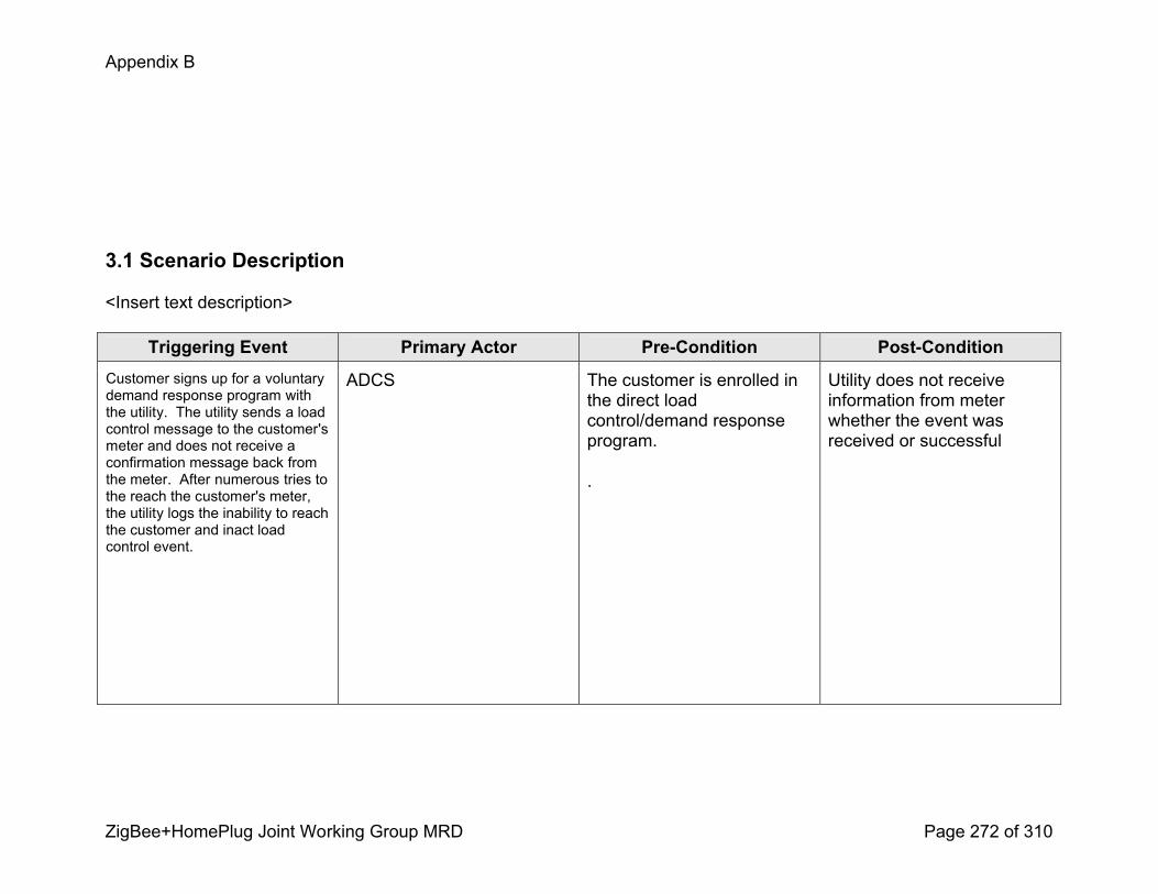
Appendix B
ZigBee+HomePlug Joint Working Group MRD Page 272 of 310
3.1 Scenario Description
<Insert text description>
Triggering Event Primary Actor PreCondition PostConditionCustomer signs up for a voluntary demand response program with the utility. The utility sends a load control message to the customer's meter and does not receive a confirmation message back from the meter. After numerous tries to the reach the customer's meter, the utility logs the inability to reach the customer and inact load control event.
ADCS The customer is enrolled in the direct load control/demand response program.
.
Utility does not receive information from meter whether the event was received or successful
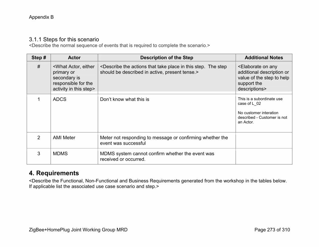
Appendix B
ZigBee+HomePlug Joint Working Group MRD Page 273 of 310
3.1.1 Steps for this scenario<Describe the normal sequence of events that is required to complete the scenario.>
Step # Actor Description of the Step Additional Notes
# <What Actor, either primary or secondary is responsible for the activity in this step>
<Describe the actions that take place in this step. The step should be described in active, present tense.>
<Elaborate on any additional description or value of the step to help support the descriptions>
1 ADCS Don’t know what this is This is a subordinate use case of L_02
No customer interation described Customer is not an Actor.
2 AMI Meter Meter not responding to message or confirming whether the event was successful
3 MDMS MDMS system cannot confirm whether the event was received or occurred.
4. Requirements<Describe the Functional, NonFunctional and Business Requirements generated from the workshop in the tables below. If applicable list the associated use case scenario and step.>

Appendix B
ZigBee+HomePlug Joint Working Group MRD Page 274 of 310
4.1 Functional Requirements
Func.Req.ID
Functional Requirement AssociatedScenario #(if applicable)
AssociatedStep #(if applicable)
4.2 NonFunctional Requirements
Nonfunc.Req.ID
NonFunctional Requirement AssociatedScenario #(if applicable)
AssociatedStep #(if applicable)
4.3 Business Requirements
Bus.Req.ID
Business Requirement AssociatedScenario #(if applicable)
AssociatedStep #(if applicable)
Appendix B
ZigBee+HomePlug Joint Working Group MRD Page 275 of 310
Load Control and Demand Response Use Case
Utility Initiates Demand ResponseL_14 – Scenario 1: REP initiates a demand response event
Appendix B
ZigBee+HomePlug Joint Working Group MRD Page 276 of 310
1.1 Use Case Title<HAN Device(s) Respond to a Utility Initiated and Monitored Demand Response Event>
1.3 Use Case Detailed Narrative<Background information, context, scope, etc.>
3. Step by Step Analysis of Each Scenario
<Describe the steps that implement the scenario. The first scenario should be classified as either a “Primary” Scenario or an “Alternate” Scenario by starting the title of the scenario with either the wor[d] “Primary” or “Alternate”. A scenario that successfully completes without exception or relying heavily on steps from another scenario should be classified as Primary; all other scenarios should be classified as “Alternate”. If there is more than one scenario (set of steps) that is relevant, make a copy of the following section (all of 3.1, including 3.1.1 and tables) and fill out the additional scenarios.>
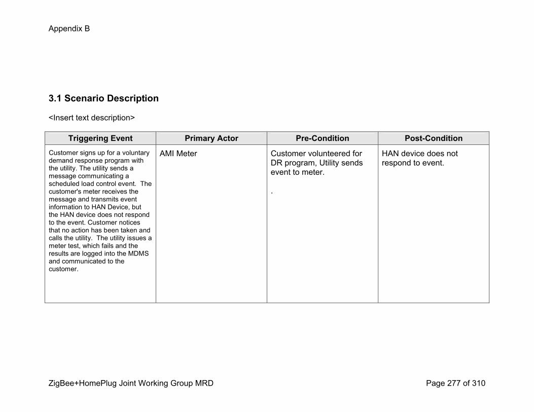
Appendix B
ZigBee+HomePlug Joint Working Group MRD Page 277 of 310
3.1 Scenario Description
<Insert text description>
Triggering Event Primary Actor PreCondition PostConditionCustomer signs up for a voluntary demand response program with the utility. The utility sends a message communicating a scheduled load control event. The customer's meter receives the message and transmits event information to HAN Device, but the HAN device does not respond to the event. Customer notices that no action has been taken and calls the utility. The utility issues a meter test, which fails and the results are logged into the MDMS and communicated to the customer.
AMI Meter Customer volunteered for DR program, Utility sends event to meter.
.
HAN device does not respond to event.
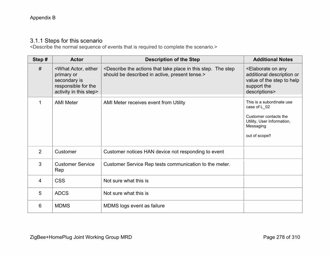
Appendix B
ZigBee+HomePlug Joint Working Group MRD Page 278 of 310
3.1.1 Steps for this scenario<Describe the normal sequence of events that is required to complete the scenario.>
Step # Actor Description of the Step Additional Notes
# <What Actor, either primary or secondary is responsible for the activity in this step>
<Describe the actions that take place in this step. The step should be described in active, present tense.>
<Elaborate on any additional description or value of the step to help support the descriptions>
1 AMI Meter AMI Meter receives event from Utility This is a subordinate use case of L_02
Customer contacts the Utility, User Information, Messaging
out of scope!!
2 Customer Customer notices HAN device not responding to event
3 Customer Service Rep
Customer Service Rep tests communication to the meter.
4 CSS Not sure what this is
5 ADCS Not sure what this is
6 MDMS MDMS logs event as failure

Appendix B
ZigBee+HomePlug Joint Working Group MRD Page 279 of 310
Step # Actor Description of the Step Additional Notes
4. Requirements<Describe the Functional, NonFunctional and Business Requirements generated from the workshop in the tables below. If applicable list the associated use case scenario and step.>
4.1 Functional Requirements
Func.Req.ID
Functional Requirement AssociatedScenario #(if applicable)
AssociatedStep #(if applicable)
4.2 NonFunctional Requirements
Nonfunc.Req.ID
NonFunctional Requirement AssociatedScenario #(if applicable)
AssociatedStep #(if applicable)
Appendix B
ZigBee+HomePlug Joint Working Group MRD Page 280 of 310
4.3 Business Requirements
Bus.Req.ID
Business Requirement AssociatedScenario #(if applicable)
AssociatedStep #(if applicable)
Appendix B
ZigBee+HomePlug Joint Working Group MRD Page 281 of 310
Load Control and Demand Response Use Case
Utility Demand Response – Opt out, Override, Cancellation
Utility or 3rd party initiates and cancels a demand response event

Appendix B
ZigBee+HomePlug Joint Working Group MRD Page 282 of 310
1.1 Use Case Title<Utility or 3rd party initiates and cancels a demand response event>
1.3 Use Case Detailed Narrative<Background information, context, scope, etc.>
3. Step by Step Analysis of Each Scenario
<Describe the steps that implement the scenario. The first scenario should be classified as either a “Primary” Scenario or an “Alternate” Scenario by starting the title of the scenario with either the wor[d] “Primary” or “Alternate”. A scenario that successfully completes without exception or relying heavily on steps from another scenario should be classified as Primary; all other scenarios should be classified as “Alternate”. If there is more than one scenario (set of steps) that is relevant, make a copy of the following section (all of 3.1, including 3.1.1 and tables) and fill out the additional scenarios.>
3.1 Scenario Description
<Insert text description>
Triggering Event Primary Actor PreCondition PostCondition
Demand Response event is instantiated
Utility or 3rd party 2.2 Scenario 1, Steps 16 will have been completed
After the utility or 3rd party cancels the demand response event, the PCT will either return to its previous state or to a new state controlled by the customer.

Appendix B
ZigBee+HomePlug Joint Working Group MRD Page 283 of 310
3.1.1 Steps for this scenario<Describe the normal sequence of events that is required to complete the scenario.>
Step # Actor Description of the Step Additional Notes
# <What Actor, either primary or secondary is responsible for the activity in this step>
<Describe the actions that take place in this step. The step should be described in active, present tense.>
<Elaborate on any additional description or value of the step to help support the descriptions>
1 AMI System Demand response event instantiated. See scenario 1, Steps 16. Demand response event is cancelled.
2 HAN Device PCT detects cancellation of demand response event, restores programmed/default state and communicates change of state to the ESI.
3 ESI ESI acknowledges PCT and records transaction (e.g. state and/or mode), sends information to AMI System.
4 AMI System AMI System receives and stores HAN device information. HAN data could be sent along with the daily meter read or can be retrieved on an on demand basis (e.g. load research requests PCT data from a targeted or group of meters).

Appendix B
ZigBee+HomePlug Joint Working Group MRD Page 284 of 310
Step # Actor Description of the Step Additional Notes
5 AMI System AMI System stores HAN device transactions for later extraction/viewing.
User interface required in the AMI System.
6
7

Appendix B
ZigBee+HomePlug Joint Working Group MRD Page 285 of 310
4. Requirements<Describe the Functional, NonFunctional and Business Requirements generated from the workshop in the tables below. If applicable list the associated use case scenario and step.>
4.1 Functional Requirements
Func.Req.ID
Functional Requirement AssociatedScenario #(if applicable)
AssociatedStep #(if applicable)
4.2 NonFunctional Requirements
Nonfunc.Req.ID
NonFunctional Requirement AssociatedScenario #(if applicable)
AssociatedStep #(if applicable)
4.3 Business Requirements
Bus.Req.ID
Business Requirement AssociatedScenario #(if applicable)
AssociatedStep #(if applicable)

Appendix B
ZigBee+HomePlug Joint Working Group MRD Page 286 of 310
Load Control and Demand Response Use Case
Utility Demand Response – Opt out, Override, Cancellation
Customer Overrides a Utility Initiated and Monitored Demand Response Event
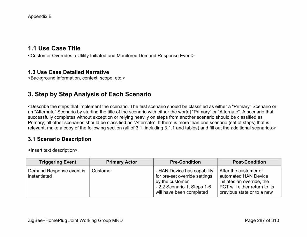
Appendix B
ZigBee+HomePlug Joint Working Group MRD Page 287 of 310
1.1 Use Case Title<Customer Overrides a Utility Initiated and Monitored Demand Response Event>
1.3 Use Case Detailed Narrative<Background information, context, scope, etc.>
3. Step by Step Analysis of Each Scenario
<Describe the steps that implement the scenario. The first scenario should be classified as either a “Primary” Scenario or an “Alternate” Scenario by starting the title of the scenario with either the wor[d] “Primary” or “Alternate”. A scenario that successfully completes without exception or relying heavily on steps from another scenario should be classified as Primary; all other scenarios should be classified as “Alternate”. If there is more than one scenario (set of steps) that is relevant, make a copy of the following section (all of 3.1, including 3.1.1 and tables) and fill out the additional scenarios.>
3.1 Scenario Description
<Insert text description>
Triggering Event Primary Actor PreCondition PostCondition
Demand Response event is instantiated
Customer HAN Device has capability for preset override settings by the customer 2.2 Scenario 1, Steps 16 will have been completed
After the customer or automated HAN Device initiates an override, the PCT will either return to its previous state or to a new

Appendix B
ZigBee+HomePlug Joint Working Group MRD Page 288 of 310
state controlled by the customer.
3.1.1 Steps for this scenario<Describe the normal sequence of events that is required to complete the scenario.>
Step # Actor Description of the Step Additional Notes
# <What Actor, either primary or secondary is responsible for the activity in this step>
<Describe the actions that take place in this step. The step should be described in active, present tense.>
<Elaborate on any additional description or value of the step to help support the descriptions>
1 AMI System Demand response event instantiated. See scenario 1, Steps 16.
2 Customer Customer or customer’s preset setting overrides demand response command.
3 HAN Device PCT communicates override message to the ESI PCT could send an override message asynchronously or it can be retrieved by a message poll from the ESI.
4 ESI ESI acknowledges receipt and records customer override transaction.
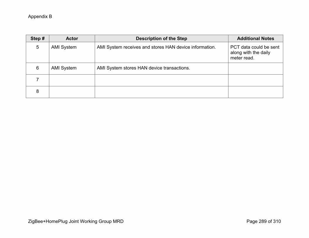
Appendix B
ZigBee+HomePlug Joint Working Group MRD Page 289 of 310
Step # Actor Description of the Step Additional Notes
5 AMI System AMI System receives and stores HAN device information. PCT data could be sent along with the daily meter read.
6 AMI System AMI System stores HAN device transactions.
7
8

Appendix B
ZigBee+HomePlug Joint Working Group MRD Page 290 of 310
4. Requirements<Describe the Functional, NonFunctional and Business Requirements generated from the workshop in the tables below. If applicable list the associated use case scenario and step.>
4.1 Functional Requirements
Func.Req.ID
Functional Requirement AssociatedScenario #(if applicable)
AssociatedStep #(if applicable)
4.2 NonFunctional Requirements
Nonfunc.Req.ID
NonFunctional Requirement AssociatedScenario #(if applicable)
AssociatedStep #(if applicable)
4.3 Business Requirements
Bus.Req.ID
Business Requirement AssociatedScenario #(if applicable)
AssociatedStep #(if applicable)
Appendix B
ZigBee+HomePlug Joint Working Group MRD Page 291 of 310
Load Control and Demand Response Use Case
Utility Demand Response – Opt out, Override, Cancellation
Customer Opts out of AMI Demand Response Program
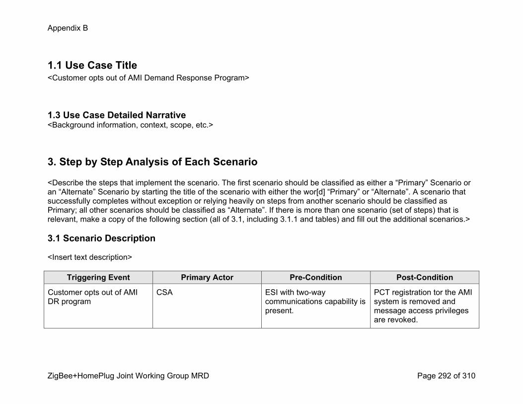
Appendix B
ZigBee+HomePlug Joint Working Group MRD Page 292 of 310
1.1 Use Case Title<Customer opts out of AMI Demand Response Program>
1.3 Use Case Detailed Narrative<Background information, context, scope, etc.>
3. Step by Step Analysis of Each Scenario
<Describe the steps that implement the scenario. The first scenario should be classified as either a “Primary” Scenario or an “Alternate” Scenario by starting the title of the scenario with either the wor[d] “Primary” or “Alternate”. A scenario that successfully completes without exception or relying heavily on steps from another scenario should be classified as Primary; all other scenarios should be classified as “Alternate”. If there is more than one scenario (set of steps) that is relevant, make a copy of the following section (all of 3.1, including 3.1.1 and tables) and fill out the additional scenarios.>
3.1 Scenario Description
<Insert text description>
Triggering Event Primary Actor PreCondition PostCondition
Customer opts out of AMI DR program
CSA ESI with twoway communications capability is present.
PCT registration tor the AMI system is removed and message access privileges are revoked.

Appendix B
ZigBee+HomePlug Joint Working Group MRD Page 293 of 310
3.1.1 Steps for this scenario<Describe the normal sequence of events that is required to complete the scenario.>
Step # Actor Description of the Step Additional Notes
# <What Actor, either primary or secondary is responsible for the activity in this step>
<Describe the actions that take place in this step. The step should be described in active, present tense.>
<Elaborate on any additional description or value of the step to help support the descriptions>
1 Customer Customer chooses to opt out of AMI Program
2 CSA CSA informs the customer information system that customer no longer wants to participate
3 Customer Information System
Customer information system denotes effective date of program termination and makes accounting adjustments as deemed necessary per the tariff guidelines
4 CSA/Field Communications
CSA selects appropriate AMI meter via the AMI Host System and removes the appropriate AMI Demand Response Program association
5 AMI Host System AMI Host System communicates the selected change to the targeted AMI Meter and informs it to terminate HAN Communications to the PCT associated with the AMI Demand Response Program.
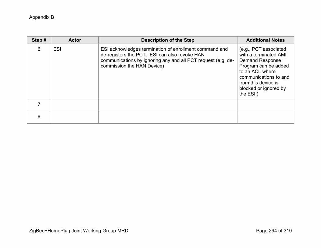
Appendix B
ZigBee+HomePlug Joint Working Group MRD Page 294 of 310
Step # Actor Description of the Step Additional Notes
6 ESI ESI acknowledges termination of enrollment command and deregisters the PCT. ESI can also revoke HAN communications by ignoring any and all PCT request (e.g. decommission the HAN Device)
(e.g., PCT associated with a terminated AMI Demand Response Program can be added to an ACL where communications to and from this device is blocked or ignored by the ESI.)
7
8

Appendix B
ZigBee+HomePlug Joint Working Group MRD Page 295 of 310
4. Requirements<Describe the Functional, NonFunctional and Business Requirements generated from the workshop in the tables below. If applicable list the associated use case scenario and step.>
4.1 Functional Requirements
Func.Req.ID
Functional Requirement AssociatedScenario #(if applicable)
AssociatedStep #(if applicable)
4.2 NonFunctional Requirements
Nonfunc.Req.ID
NonFunctional Requirement AssociatedScenario #(if applicable)
AssociatedStep #(if applicable)
4.3 Business Requirements
Bus.Req.ID
Business Requirement AssociatedScenario #(if applicable)
AssociatedStep #(if applicable)

Appendix B
ZigBee+HomePlug Joint Working Group MRD Page 296 of 310
Load Control and Demand Response Use Case
HAN Devices Requests and Responds
HAN Device requests load and energy management data from HAN device(s)
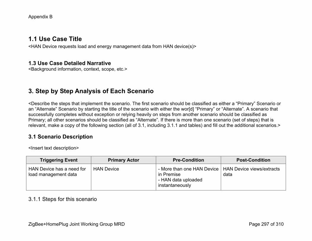
Appendix B
ZigBee+HomePlug Joint Working Group MRD Page 297 of 310
1.1 Use Case Title<HAN Device requests load and energy management data from HAN device(s)>
1.3 Use Case Detailed Narrative<Background information, context, scope, etc.>
3. Step by Step Analysis of Each Scenario
<Describe the steps that implement the scenario. The first scenario should be classified as either a “Primary” Scenario or an “Alternate” Scenario by starting the title of the scenario with either the wor[d] “Primary” or “Alternate”. A scenario that successfully completes without exception or relying heavily on steps from another scenario should be classified as Primary; all other scenarios should be classified as “Alternate”. If there is more than one scenario (set of steps) that is relevant, make a copy of the following section (all of 3.1, including 3.1.1 and tables) and fill out the additional scenarios.>
3.1 Scenario Description
<Insert text description>
Triggering Event Primary Actor PreCondition PostCondition
HAN Device has a need for load management data
HAN Device More than one HAN Device in Premise HAN data uploaded instantaneously
HAN Device views/extracts data
3.1.1 Steps for this scenario
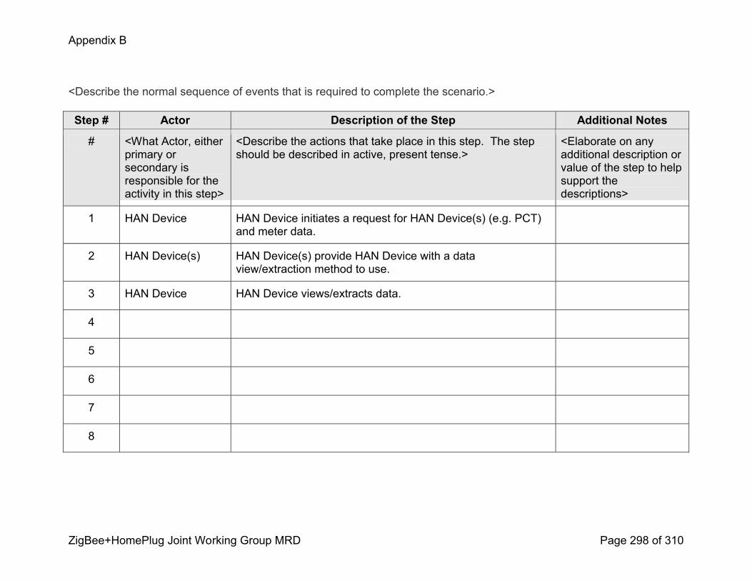
Appendix B
ZigBee+HomePlug Joint Working Group MRD Page 298 of 310
<Describe the normal sequence of events that is required to complete the scenario.>
Step # Actor Description of the Step Additional Notes
# <What Actor, either primary or secondary is responsible for the activity in this step>
<Describe the actions that take place in this step. The step should be described in active, present tense.>
<Elaborate on any additional description or value of the step to help support the descriptions>
1 HAN Device HAN Device initiates a request for HAN Device(s) (e.g. PCT) and meter data.
2 HAN Device(s) HAN Device(s) provide HAN Device with a data view/extraction method to use.
3 HAN Device HAN Device views/extracts data.
4
5
6
7
8

Appendix B
ZigBee+HomePlug Joint Working Group MRD Page 299 of 310
4. Requirements<Describe the Functional, NonFunctional and Business Requirements generated from the workshop in the tables below. If applicable list the associated use case scenario and step.>
4.1 Functional Requirements
Func.Req.ID
Functional Requirement AssociatedScenario #(if applicable)
AssociatedStep #(if applicable)
4.2 NonFunctional Requirements
Nonfunc.Req.ID
NonFunctional Requirement AssociatedScenario #(if applicable)
AssociatedStep #(if applicable)
4.3 Business Requirements
Bus.Req.ID
Business Requirement AssociatedScenario #(if applicable)
AssociatedStep #(if applicable)

Appendix B
ZigBee+HomePlug Joint Working Group MRD Page 300 of 310
Load Control and Demand Response Use Case
HAN Devices Requests and Responds
HAN Device responds to requests for load and energy management data

Appendix B
ZigBee+HomePlug Joint Working Group MRD Page 301 of 310
1.1 Use Case Title<HAN Device responds to requests for load and energy management data>
1.3 Use Case Detailed Narrative<Background information, context, scope, etc.>
3. Step by Step Analysis of Each Scenario
<Describe the steps that implement the scenario. The first scenario should be classified as either a “Primary” Scenario or an “Alternate” Scenario by starting the title of the scenario with either the wor[d] “Primary” or “Alternate”. A scenario that successfully completes without exception or relying heavily on steps from another scenario should be classified as Primary; all other scenarios should be classified as “Alternate”. If there is more than one scenario (set of steps) that is relevant, make a copy of the following section (all of 3.1, including 3.1.1 and tables) and fill out the additional scenarios.>
3.1 Scenario Description
<Insert text description>
Triggering Event Primary Actor PreCondition PostCondition
AMI System has a need for load management data
HAN Device HAN Device is connected to AMI System
AMI System views/extracts data
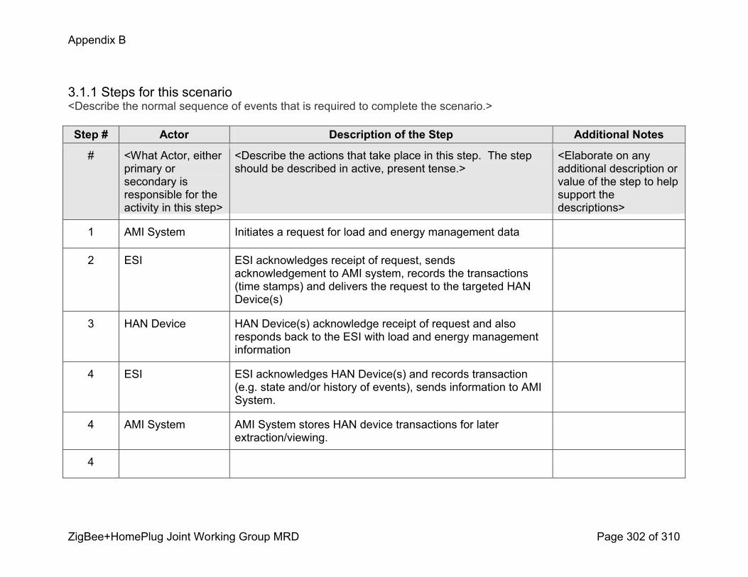
Appendix B
ZigBee+HomePlug Joint Working Group MRD Page 302 of 310
3.1.1 Steps for this scenario<Describe the normal sequence of events that is required to complete the scenario.>
Step # Actor Description of the Step Additional Notes
# <What Actor, either primary or secondary is responsible for theactivity in this step>
<Describe the actions that take place in this step. The step should be described in active, present tense.>
<Elaborate on any additional description or value of the step to help support the descriptions>
1 AMI System Initiates a request for load and energy management data
2 ESI ESI acknowledges receipt of request, sends acknowledgement to AMI system, records the transactions (time stamps) and delivers the request to the targeted HAN Device(s)
3 HAN Device HAN Device(s) acknowledge receipt of request and also responds back to the ESI with load and energy management information
4 ESI ESI acknowledges HAN Device(s) and records transaction (e.g. state and/or history of events), sends information to AMI System.
4 AMI System AMI System stores HAN device transactions for later extraction/viewing.
4
Appendix B
ZigBee+HomePlug Joint Working Group MRD Page 303 of 310
Step # Actor Description of the Step Additional Notes
5
6
7
8
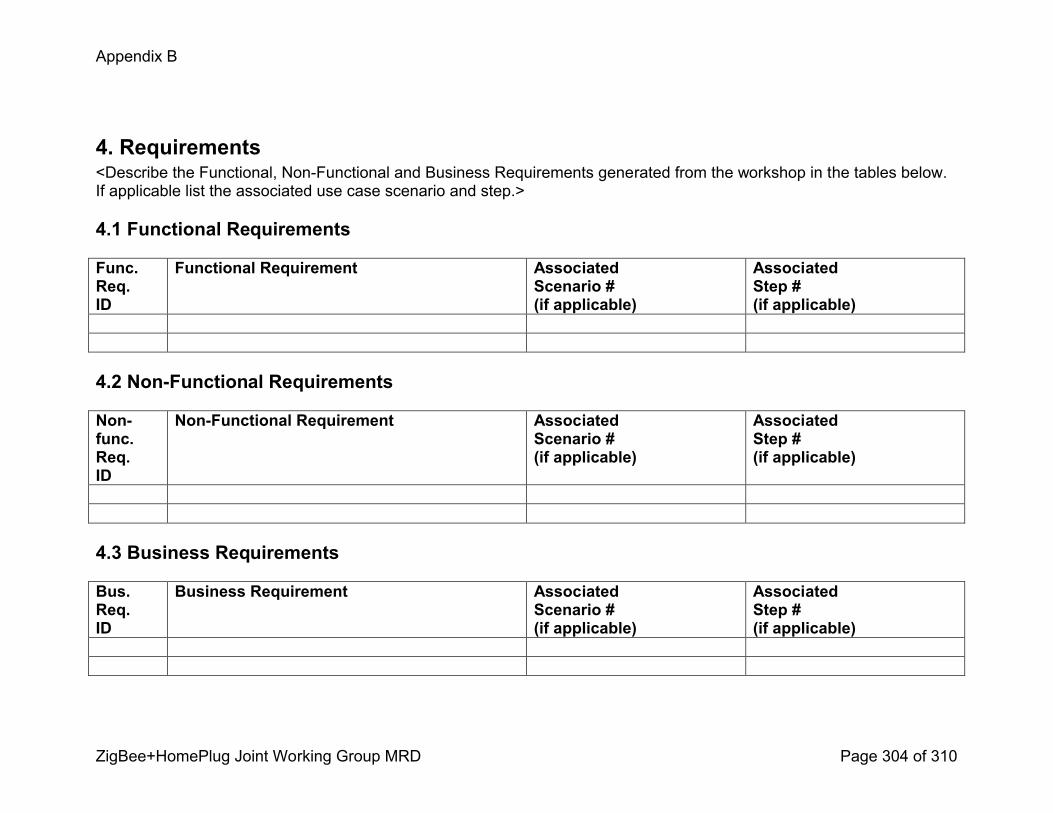
Appendix B
ZigBee+HomePlug Joint Working Group MRD Page 304 of 310
4. Requirements<Describe the Functional, NonFunctional and Business Requirements generated from the workshop in the tables below. If applicable list the associated use case scenario and step.>
4.1 Functional Requirements
Func.Req.ID
Functional Requirement AssociatedScenario #(if applicable)
AssociatedStep #(if applicable)
4.2 NonFunctional Requirements
Nonfunc.Req.ID
NonFunctional Requirement AssociatedScenario #(if applicable)
AssociatedStep #(if applicable)
4.3 Business Requirements
Bus.Req.ID
Business Requirement AssociatedScenario #(if applicable)
AssociatedStep #(if applicable)
Appendix B
ZigBee+HomePlug Joint Working Group MRD Page 305 of 310
Load Control and Demand Response Use Case
HAN Devices Requests and Responds
HAN Device Sends State Changes to AMI Host System
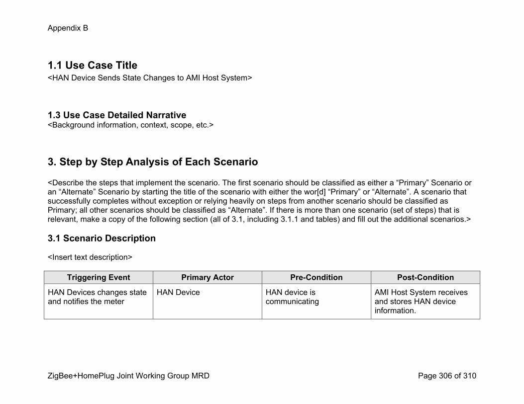
Appendix B
ZigBee+HomePlug Joint Working Group MRD Page 306 of 310
1.1 Use Case Title<HAN Device Sends State Changes to AMI Host System>
1.3 Use Case Detailed Narrative<Background information, context, scope, etc.>
3. Step by Step Analysis of Each Scenario
<Describe the steps that implement the scenario. The first scenario should be classified as either a “Primary” Scenario or an “Alternate” Scenario by starting the title of the scenario with either the wor[d] “Primary” or “Alternate”. A scenario that successfully completes without exception or relying heavily on steps from another scenario should be classified as Primary; all other scenarios should be classified as “Alternate”. If there is more than one scenario (set of steps) that is relevant, make a copy of the following section (all of 3.1, including 3.1.1 and tables) and fill out the additional scenarios.>
3.1 Scenario Description
<Insert text description>
Triggering Event Primary Actor PreCondition PostCondition
HAN Devices changes state and notifies the meter
HAN Device HAN device is communicating
AMI Host System receives and stores HAN device information.
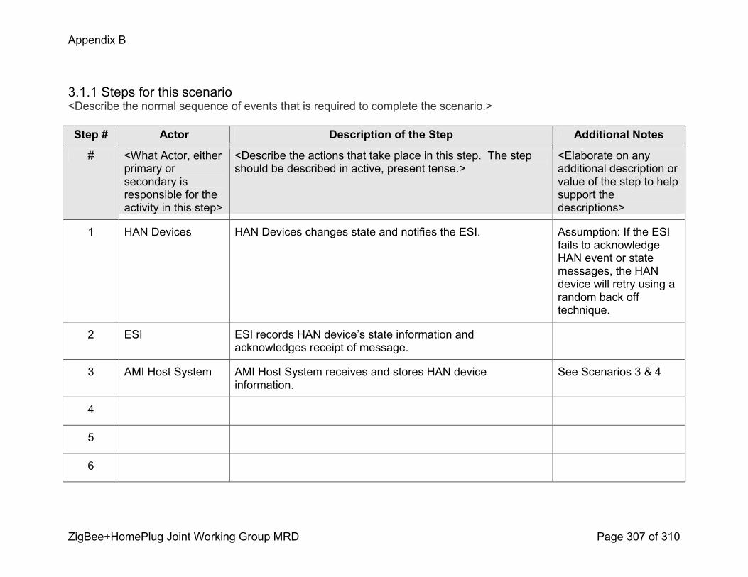
Appendix B
ZigBee+HomePlug Joint Working Group MRD Page 307 of 310
3.1.1 Steps for this scenario<Describe the normal sequence of events that is required to complete the scenario.>
Step # Actor Description of the Step Additional Notes
# <What Actor, either primary or secondary is responsible for the activity in this step>
<Describe the actions that take place in this step. The step should be described in active, present tense.>
<Elaborate on any additional description or value of the step to help support the descriptions>
1 HAN Devices HAN Devices changes state and notifies the ESI. Assumption: If the ESI fails to acknowledge HAN event or state messages, the HAN device will retry using a random back off technique.
2 ESI ESI records HAN device’s state information and acknowledges receipt of message.
3 AMI Host System AMI Host System receives and stores HAN device information.
See Scenarios 3 & 4
4
5
6
Appendix B
ZigBee+HomePlug Joint Working Group MRD Page 308 of 310
Step # Actor Description of the Step Additional Notes
7
8

Appendix B
ZigBee+HomePlug Joint Working Group MRD Page 309 of 310
4. Requirements<Describe the Functional, NonFunctional and Business Requirements generated from the workshop in the tables below. If applicable list the associated use case scenario and step.>
4.1 Functional Requirements
Func.Req.ID
Functional Requirement AssociatedScenario #(if applicable)
AssociatedStep #(if applicable)
4.2 NonFunctional Requirements
Nonfunc.Req.ID
NonFunctional Requirement AssociatedScenario #(if applicable)
AssociatedStep #(if applicable)
4.3 Business Requirements
Bus.Req.ID
Business Requirement AssociatedScenario #(if applicable)
AssociatedStep #(if applicable)

Appendix B
ZigBee+HomePlug Joint Working Group MRD Page 310 of 310