Small-Scale Hydropower Optimization ME/EE Senior Design Project 2004/2005 Customer: John Law...
15
Small-Scale Hydropower Small-Scale Hydropower Optimization Optimization ME/EE Senior Design Project 2004/2005 ME/EE Senior Design Project 2004/2005 Customer: John Law Customer: John Law Mentors: Ralph Budwig (ME), Brian Johnson (EE) Mentors: Ralph Budwig (ME), Brian Johnson (EE) Phillip Arpke Phillip Arpke Kelly Jobes Kelly Jobes Jamin Juhasz Jamin Juhasz Karl Krohmer Karl Krohmer Jill Nieborsky Jill Nieborsky
-
date post
21-Dec-2015 -
Category
Documents
-
view
214 -
download
0
Transcript of Small-Scale Hydropower Optimization ME/EE Senior Design Project 2004/2005 Customer: John Law...

Small-Scale Hydropower Small-Scale Hydropower OptimizationOptimization
Small-Scale Hydropower Small-Scale Hydropower OptimizationOptimization
ME/EE Senior Design Project 2004/2005ME/EE Senior Design Project 2004/2005
Customer: John LawCustomer: John Law
Mentors: Ralph Budwig (ME), Brian Johnson (EE)Mentors: Ralph Budwig (ME), Brian Johnson (EE)
Phillip ArpkePhillip ArpkeKelly JobesKelly Jobes
Jamin JuhaszJamin JuhaszKarl KrohmerKarl KrohmerJill NieborskyJill Nieborsky

Problem DefinitionProblem DefinitionProblem DefinitionProblem Definition
Optimize Small-scale Hydropower System For Optimize Small-scale Hydropower System For Residential HeatingResidential Heating
The Generator Is Capable Of Providing 3.7 kW The Generator Is Capable Of Providing 3.7 kW Power Power
Last Spring During Maximum Flow, The Last Spring During Maximum Flow, The Generator Provided Only 1 kW Of PowerGenerator Provided Only 1 kW Of Power

ConstraintsConstraintsConstraintsConstraints Site Vs. Lab ConditionsSite Vs. Lab Conditions
Site: 9 cfs and 40 ft/sSite: 9 cfs and 40 ft/s Lab: 1 cfs and 16 ft/sLab: 1 cfs and 16 ft/s
Inherited FeaturesInherited Features Three-phase Three-phase
Generator Sunk CostGenerator Sunk Cost 12-inch Penstock 12-inch Penstock
Pipe To 6-inch RoundPipe To 6-inch Round On/Off Operation On/Off Operation
With Maximum FlowWith Maximum Flow
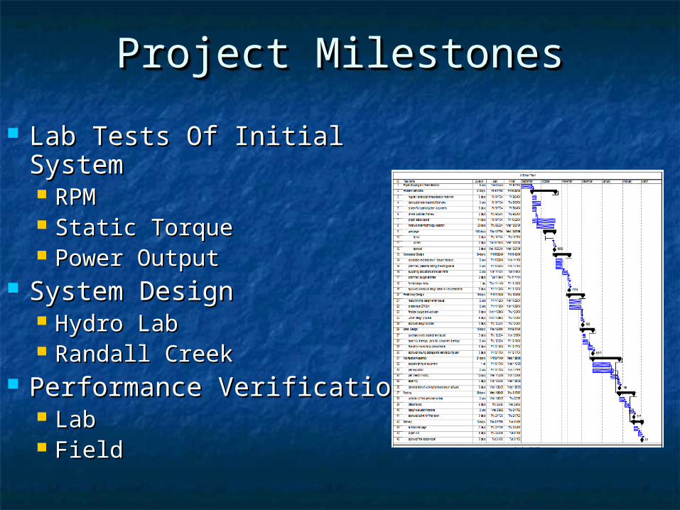
Project MilestonesProject MilestonesProject MilestonesProject Milestones
Lab Tests Of Initial Lab Tests Of Initial SystemSystem RPMRPM Static TorqueStatic Torque Power OutputPower Output
System DesignSystem Design Hydro LabHydro Lab Randall CreekRandall Creek
Performance VerificationPerformance Verification LabLab FieldField

Cross-flow Turbine Cross-flow Turbine BackgroundBackground
Cross-flow Turbine Cross-flow Turbine BackgroundBackground
Banki TurbineBanki Turbine Top Water EntryTop Water Entry Falling ActionFalling Action =80%=80%

Design ImprovementsDesign ImprovementsDesign ImprovementsDesign Improvements
Increased Power OutputIncreased Power Output Nozzle RedesignNozzle Redesign Reduced Water Drag In Reduced Water Drag In
“Hot Spot”“Hot Spot” Viewing WindowViewing Window
Old Configuration
New Configuration

Nozzle Design (Lab)Nozzle Design (Lab)Nozzle Design (Lab)Nozzle Design (Lab)
Design Based On Fluid Velocity (16 ft/s)Design Based On Fluid Velocity (16 ft/s) 15.75 in15.75 in22 Cross-sectional Area Cross-sectional Area Hydraulic Area Constant From Round To Hydraulic Area Constant From Round To
Square Square

Nozzle Design (Field)Nozzle Design (Field)Nozzle Design (Field)Nozzle Design (Field) Design Based On Flow Rate (9.63 ftDesign Based On Flow Rate (9.63 ft33/s)/s) 31.875 in31.875 in22 Cross-sectional Area Cross-sectional Area Hydraulic Area Constant From Round To Hydraulic Area Constant From Round To
SquareSquare

Housing DesignHousing DesignHousing DesignHousing Design
Eliminated Water Drag In “Hot Spot”Eliminated Water Drag In “Hot Spot” Plexiglas Top For Viewing Flow Plexiglas Top For Viewing Flow
PatternPattern

Electrical SchematicElectrical SchematicElectrical SchematicElectrical Schematic Three ComponentsThree Components
Resistive Heating Load (12 Resistive Heating Load (12 ΩΩ)) Capacitor Bank (135 µF)Capacitor Bank (135 µF) Induction GeneratorInduction Generator

ManufacturingManufacturingManufacturingManufacturing
Welding Test Nozzle Installing the Runner
Fitting Circular Flange to Lab Nozzle
Bridgeport CNC Machine

TestingTestingTestingTesting
Measured Generator and Turbine RPMMeasured Generator and Turbine RPMWith No-load, Shunt Capacitors Only, and With No-load, Shunt Capacitors Only, and 12 12 ΩΩ Load With Shunt Capacitance Load With Shunt Capacitance
Measured Power Output For Three CasesMeasured Power Output For Three Cases Measured Static TorqueMeasured Static Torque
TurbineGeneratorElectrical Box
Water Supply

Laboratory ResultsLaboratory ResultsLaboratory ResultsLaboratory Results
RPM TestsRPM Tests Turbine Turbine GeneratoGeneratorr % Improvement% Improvement
Free-Spin RPM Test 409 RPM 81
No Load RPM Test297.5
RPM1785
RPM 20
Capacitors w/o Load 201 RPM
1171 RPM 13
w/Capacitors w/Load 218 RPM
1271 RPM 12
Static Torque Static Torque TestTest Force (lb)Force (lb)
% % ImprovemenImprovementt
2-ft Arm 15.5 34
3-ft Arm 10.25 32Electrical Power Electrical Power
(Watts)(Watts) % Improvement% Improvement
141.4 53
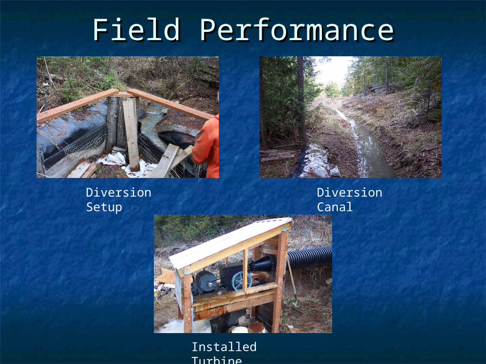
Field PerformanceField PerformanceField PerformanceField Performance
Diversion Setup
Diversion Canal
Installed Turbine