Small Scale Ferry Terminal Feasibility Study at Berkeley ...
82
655 Montgomery Street Suite 1010 San Francisco California 94111 USA | 11125268 | September 2018 Small Scale Ferry Terminal Feasibility Study at Berkeley Municipal Pier City of Berkeley September 12, 2018 Draft for City Review This document is in draft form. A final version of this document may differ from this draft. As such, the contents of this draft document shall not be relied upon. GHD disclaims any responsibility or liability arising from decisions made based on this draft document.
Transcript of Small Scale Ferry Terminal Feasibility Study at Berkeley ...

655 Montgomery Street Suite 1010 San Francisco California 94111 USA | 11125268 | September 2018
Small Scale Ferry Terminal Feasibility Study at Berkeley Municipal Pier
City of Berkeley
September 12, 2018
Draft for City Review This document is in draft form. A final version of this document may differ from this draft. As such, the contents of this draft document shall not be relied upon. GHD disclaims any responsibility or liability arising from decisions made based on this draft document.

Draft Document – For Discussion Only – Final Version May Differ From Draft
GHD | Small Scale Ferry Terminal Feasibility Study | 11125268 | Page i
Executive Summary
Background
GHD Inc. (GHD) has been retained by the City of Berkeley (City) to evaluate the feasibility of passenger ferry service at the Berkeley Municipal Pier, Berkeley, CA. The study focused on the waterside improvements needed for a ferry terminal and integration of a terminal with a new dual purpose pier that could be used by the public for recreation in addition providing access to the terminal.
The City may choose to advance the planning and preliminary design of a ferry terminal located at Municipal Pier in coordination with San Francisco Bay Ferry Water Emergency Transportation Authority (WETA.) It is assumed that WETA will operate and maintain the ferry terminal. Standard practice developed by WETA for their San Francisco Bay Area ferry terminals will be followed for the concept design of the Berkeley Ferry Terminal.
A terminal located at Municipal Pier would provide passenger ferry service between the City of Berkeley and San Francisco. A replacement pier will offer both viewing and recreational opportunities for the public in addition to serving as the approach access point for a ferry terminal.
In November 2017 GHD completed a condition assessment and structural evaluation of the existing Municipal Pier located near the Berkeley Marina. The study objective was to perform a visual condition survey of the pier structure and prepare a report on the conditions along with conceptual repair alternatives and budgetary cost estimates.
Results of the assessment confirmed the City of Berkeley’s (City) decision to close the pier for public use in July 2015. GHD’s evaluation showed that Municipal Pier requires extensive structural repair to reopen the pier for public use as a result of the deterioration of the concrete sustained due to exposure to the marine environment. Due to the relatively high estimated construction cost for rehabilitation and strengthening of the pier, replacement of the structure is recommended. GHD recommended that the City consider the replacement pier alternatives which meets all of the required parameters while providing a safe, recreational and viewing opportunity for the public.
Scope of Ferry Feasibility Study
GHD was requested by the City of Berkeley (City) to conduct a feasibility study of a passenger ferry terminal to be located near the existing Berkeley Municipal Pier at Seawall Drive adjacent to Berkeley Marina. The intent of the study is to review existing conditions and develop concepts for a ferry terminal and review feasibility of passenger ferry operations and budgetary cost.
Study Conclusions and Recommendations
GHD reviewed the feasibility of utilizing a shorter, replacement pier as an access point to the passenger ferry terminal. A dual purpose pier would be suitable to provide access point to the terminal in additional to a recreational pier and public observation area.
We also note that the existing pier structure is not suitable for a passenger ferry terminal due to extensive modifications, repairs and strengthening required. The required upgrades will require extensive and costly strengthening as shown in GHD’s structural assessment report. In addition,

Draft Document – For Discussion Only – Final Version May Differ From Draft
GHD | Small Scale Ferry Terminal Feasibility Study | 11125268 | Page ii
passenger ferry terminals operated by WETA are considered Essential Facilities and must meet present building code requirements for ductility and resistance to seismic loads at different earthquake levels to remain operable for safe public use.
Two alternative locations were developed for the conceptual ferry terminal and dual purpose pier location. The pier in the ferry terminal feasibility study was based on replacement concepts developed in GHD’s Municipal Pier Structural Assessment report.
We find that a ferry terminal will be feasible at the project sites reviewed in this study. The conclusions drawn rely on use of low-draft ferry vessels and dredging is required for safe navigation over the tidal range.
The current small-scale study focuses only on the pier and waterside improvements needed for a ferry terminal. Landside improvements will need to be studied and concepts and cost estimates developed. Transportation to the terminal and parking should be reviewed. ADA-accessibility from the parking areas to the terminal also will require review.
We note that coastal conditions at the Berkeley site are more energetic than any other ferry terminal in San Francisco Bay. The site is shallow, with depths less than 10 feet for several miles offshore. Wave conditions were generated and existing depths evaluated using a new hydrographic survey. Sedimentation was investigated through comparison with previous hydrographic surveys. Analysis indicates that sedimentation near the project site (landward end of the pier) from 1979 to present is less than 1 inch per year on average.
A range of depths for the navigation channel and berth area were investigated, using the expected vessel underkeel clearance during two years of typical conditions as a criterion for suitability to provide safe and efficient operations. Underkeel clearance was evaluated based on the draft of the proposed low-draft ferry, wave conditions, expected wave-induced motions, and tides. Results indicates that tidal disadvantage (negative tides) generate the highest level of potential downtime caused by insufficient water depth, however wave-induced motions also play a role.
The initial ferry terminal alternatives were assumed to utilize the majority of the Federal Channel (US Army Corps of Engineers) which provides access to the Berkeley Marina. The Federal Channel is a 100-ft wide channel to deep water; however, this channel is not maintained to sufficient depth for ferry operations. Based on this major assumption that the ferries will utilize the Federal Channel, two berth concepts were developed that utilized either a new pier structure on the existing alignment (Option A), or a new pier South of the existing pier (Option B). Multiple factors were considered in development of the navigation channel and berth/terminal layouts, including maneuvering considerations such as float proximity to the existing Berkeley Pier, general maneuverability in winds and waves and conflicts with traffic with Berkeley Marina.
Both options require removal of approximately 400 feet of the existing pier, since both options are situated on the south side of the existing pier. Options on the north side of the existing pier were not considered due to small craft traffic from Berkeley Marina. Dredging volumes are essentially the same for Options A and B and were generated for a range of potential channel/berth authorized depths. Since WETA has no prescribed channel design regulations or guidelines, the potential downtime or impact to operations due to insufficient depth are presented here for discussion

Draft Document – For Discussion Only – Final Version May Differ From Draft
GHD | Small Scale Ferry Terminal Feasibility Study | 11125268 | Page iii
purposes. The results of the analysis are intended to provide the City of Berkeley with an understanding of the potential imitations and costs associated with particular channel depth options.
From the perspectives of pier terminal access, coastal processes, dredging and terminal design/operations, either Option A or B is feasible. A rough estimation of costs for the conceptual improvements has been developed and is included in the feasibility study report.
As wave protection was not considered in this study, we also recommend that protection for the ferry terminal be studied to review impacts to ferry operation and schedule and whether a wave attenuator or breakwater could be used to mitigate impacts to ferry schedule and operations.

Draft Document – For Discussion Only – Final Version May Differ From Draft
GHD | Small Scale Ferry Terminal Feasibility Study | 11125268 | Page i
Table of Contents
1. Introduction ................................................................................................................................... 1
2. Study Scope and Objectives ........................................................................................................ 1
3. Ferry Terminal Design Criteria ..................................................................................................... 3
3.1 Preliminary Ferry Terminal Design Criteria ........................................................................ 3
4. Ferry Terminal Concepts .............................................................................................................. 4 4.1 Proposed Terminal Design Concepts ................................................................................ 4
4.1.1 Option A – Ferry Terminal on Existing Pier Alignment ..................................... 5 4.1.2 Option B – Ferry Terminal at South Pier Location ............................................ 6 4.1.3 Ferry Float Alignments ..................................................................................... 8
4.2 Conceptual Replacement Pier ......................................................................................... 10 4.3 Conceptual Ferry Float .................................................................................................... 13
4.3.1 Float Design .................................................................................................... 14 4.3.2 Recommended Float Option ........................................................................... 15 4.3.3 Security Gate .................................................................................................. 16
4.4 Conceptual Ferry Terminal Gangway .............................................................................. 17 4.4.1 Water Elevations............................................................................................. 17 4.4.2 Pier Deck Elevation and Float Freeboard ...................................................... 18 4.4.3 Gangway Length at Low Water Levels ........................................................... 18 4.4.4 Gangway Length Evaluation ........................................................................... 18
5. Preliminary Dredging Design and Sedimentation Rates ............................................................ 19 5.1 Site Coastal Conditions .................................................................................................... 19
5.2 Site Conditions – Bathymetry and Sedimentation ........................................................... 19
5.3 Preliminary Dredging Volumes ........................................................................................ 23
5.4 Tides ................................................................................................................................ 24
5.5 Wind-Wave Environment ................................................................................................. 24
6. Ferry Vessel Type, Navigation and Operations Evaluation ....................................................... 26 6.1 Channel Depth Evaluation ............................................................................................... 26
6.2 Vessel Underkeel Clearance ........................................................................................... 26
6.3 Channel Evaluation Results ............................................................................................. 28
7. Anticipated Permits and Approvals ............................................................................................ 30
8. Conclusions and Recommendations for Further Study ............................................................. 32
8.1 Preliminary Conclusions .................................................................................................. 32
8.2 Recommendations for Further Study ............................................................................... 33

Draft Document – For Discussion Only – Final Version May Differ From Draft
GHD | Small Scale Ferry Terminal Feasibility Study | 11125268 | Page ii
8.2.1 Develop Parking Alternatives ......................................................................... 33 8.2.2 Topographic Study ......................................................................................... 33 8.2.3 Review Parking Layouts ................................................................................. 33 8.2.4 Review of Landside Utilities ............................................................................ 33 8.2.5 Develop Initial Concept Site Plans ................................................................. 33 8.2.6 Review initial concept site plans with City and WETA .................................... 34 8.2.7 Refine preferred site plan ............................................................................... 34 8.2.8 Review preferred site plan with BCDC, City, WETA and Public .................... 34 8.2.9 Perform wave protection assessment ............................................................ 34 8.2.10 Preliminary geotechnical engineering assessment ........................................ 34 8.2.11 Refine dual purpose pier concepts ................................................................. 35 8.2.12 Develop preliminary cost estimates ................................................................ 35
Figure Index
Figure 1 – Proposed Project Site Location ............................................................................................. 3
Figure 2: Option A ferry terminal concept, located on the south side of existing pier alignment ........... 5
Figure 3 – Option A Ferry Terminal at Existing Pier Alignment ............................................................. 6
Figure 4: Option B ferry terminal concept, located at a new south pier location .................................... 7
Figure 5 – Option B Ferry Terminal at New South Pier Location ........................................................... 8
Figure 6: Wave extraction points near Berkeley Pier Ferry Terminal (top) and wave rose-histogram plot associated with point 1076 (bottom). ................................................................................. 9
Figure 7 – Wave-Rose Histogram ........................................................................................................ 10
Figure 8 – Replacement Pier Concept using Monopile Bents ............................................................. 11
Figure 9 – Replacement Pier Concept using Two Concrete Pile Bents............................................... 12
Figure 10 – Conceptual Ferry Float Section ........................................................................................ 16
Figure 11: May 2018 multibeam hydrographic survey at Berkeley Pier (eTrac) .................................. 20
Figure 12: Combined 2007 single beam hydrographic survey at Berkeley Pier (USACE and Coast & Harbor Engineering) .................................................................................................................... 20
Figure 13:1978-1979 single beam hydrographic survey at Berkeley Pier (NOAA) .............................. 21
Figure 14: Measured sedimentation, 1979 to 2018 .............................................................................. 22
Figure 15: Measured sedimentation, 2007 to 2018 .............................................................................. 22
Figure 16: Dredging volumes for Option A and B, for various dredging depths .................................. 23
Figure 17: Predicted significant wave heights during 12-mph winds from due West (270 degrees True North), as an example ..................................................................................................... 25
Figure 18: Wave and tide conditions during two-year period (2013 and 2014), extracted at most energetic location along navigation channel ................................................................................... 25

Draft Document – For Discussion Only – Final Version May Differ From Draft
GHD | Small Scale Ferry Terminal Feasibility Study | 11125268 | Page iii
Figure 19: Factors affecting underkeel clearance ................................................................................ 27
Figure 20: Response Amplitude Operators (RAOs) for Heave (left) and Pitch (right) for catamaran ferry at 30 knots in head seas (Lin et al 2017). ........................................................................... 28
Figure 21: Daily (hour by hour) distribution of wind speeds greater than 10 mph ............................... 29
Figure 22: Daily (hour by hour) distribution of underkeel clearances less than 3 feet for channel depth 7.5 feet (MLLW) ..................................................................................................................... 30
Table Index
Table 1: Tidal Datum Information for Berkeley (NOAA Station 9414816) ............................................ 24
Table 2 - Ferry Vessel Characteristics ................................................................................................. 26
Table 3 - Annual Hourly Instance for Underkeel Clearance Less than 1 to 3 feetfor Channel Depths 7.5 to 9.0 feet (MLLW) ............................................................................................................... 28
Appendix Index Appendix A Conceptual Ferry Terminal Drawings
Appendix B Coastal Engineering Analysis Report
Appendix C Design Criteria Memorandum
Appendix D Budgetary Cost Estimates

Draft Document – For Discussion Only – Final Version May Differ From Draft
GHD | Small Scale Ferry Terminal Feasibility Study | 11125268 | Page 1
1. Introduction
GHD Inc. (GHD) has been retained by the City of Berkeley (City) to evaluate the feasibility of passenger ferry service at the Berkeley Municipal Pier, Berkeley, CA. The study focused on the waterside improvements needed for a ferry terminal and integration of the terminal with a new dual purpose pier that could be used by the public for recreation in addition providing access to the terminal.
2. Study Scope and Objectives
GHD’s work scope for the small-scale ferry terminal study also included development of feasibility-level options for a navigation channel and berth/terminal, to be developed in combination with Berkeley Municipal Pier rehabilitation or replacement. The project location is shown on Figure 1. As part of the analysis, the GHD team evaluated site coastal conditions, sedimentation, channel and berth depth alternatives and their respective operational limitations, and generated navigation channel/berth layouts and estimated dredging volumes. The feasibility study will review two alternative locations for the proposed terminal. The two locations considered are as follows:
Option A – Existing Pier alignment – ferry terminal located on south side of pier
Option B – New Pier location (midway between existing pier and Hs. Lordships restaurant) – ferry located on north side of pier
The GHD team is to identify types of passenger ferry vessels that would be suitable for operation at Berkeley Municipal Pier. Conceptual modifications to the pier structure needed for vessel berthing, mooring and passenger loading and unloading will be identified.
The team will evaluate required channel depths, considering navigation effects (vessel motions, under keel clearance requirements, etc.), sedimentation, advanced maintenance dredging, and other factors. These analyses will result in a proposed dredging depth at the berth and in the channel, as well as estimated maintenance dredging volumes.
The feasibility study scope of work includes a rough order magnitude cost estimate of the conceptual ferry terminal, dual purpose pier and dredging. Concept drawings were developed for the ferry terminal alternative locations.
Develop Ferry Terminal Design Criteria
Develop coastal conditions to be used for pier assessment, including water levels, winds, wind-waves, and sea level rise. Analysis will be conducted using empirical methods to provide approximate loads on the pier deck and vertical piles.
Develop Ferry Terminal Concepts
Develop concepts for the ferry terminal type and location and review feasibility in terms of public use, safety, security, vessel navigation and cost. ADA-accessibility requirements for the terminal

Draft Document – For Discussion Only – Final Version May Differ From Draft
GHD | Small Scale Ferry Terminal Feasibility Study | 11125268 | Page 2
gangway will also be reviewed using varying tide levels. Rough order magnitude cost estimates for the ferry terminal alternatives will be provided.
Dredging Concept Design and Sedimentation Study
As part of the ferry terminal feasibility analysis, capital and maintenance dredging requirements will be estimated using existing and new hydrographic survey data and estimated sedimentation at the site. Estimates will include volumes for dredging to various channel bottom elevations, as required by particular types of vessels under consideration. Channel depth and length alternatives will be evaluated and conceptual-level cost estimates developed for the capital and maintenance dredging. Cost estimates will be developed using a basic methodology and discussion with contractors and will be feasibility-level in nature. Work includes evaluation of coastal conditions, site bathymetry and sedimentation, development of terminal channel and berthing area concepts, and potential downtime associated with shallow water limitations for various navigation channel and berth depths.
Ferry Vessel Type and Operations Evaluation
Ferry vessel types will be evaluated to determine which types of vessel are desirable and the channel depths the vessels require for safe operation. Downtime evaluation will also be performed to evaluate the potential frequency of cancelled sailings or sailings that must proceed at low speed due to lack of sufficient under keel clearance. These conditions may occur periodically for certain types of vessels due to a combination of minus tides and/or high winds (waves). Ferry vessel behavior at speed and in waves will be taken from discussion with boat builders and others and no numerical modeling of vessel motions will be performed.
Develop Conceptual Site Drawings
Ferry Terminal Conceptual Drawings – develop drawings for the conceptual ferry terminal at two alternative locations.
Provide Recommendation for Further Study
Provide recommendations for further study and discussion with the City and WETA.

Draft Document – For Discussion Only – Final Version May Differ From Draft
GHD | Small Scale Ferry Terminal Feasibility Study | 11125268 | Page 3
Figure 1 – Proposed Project Site Location
3. Ferry Terminal Design Criteria
3.1 Preliminary Ferry Terminal Design Criteria
Preliminary design criteria has been developed for the conceptual ferry terminal at Municipal Pier (Appendix D.) WETA will require that the ferry terminal be designed to Essential Facility standards per 2016 California Building Code (Title 24.)
The terminal will be used by WETA ferry vessels for passenger loading and unloading. Two vessel berths will be accommodated at the ferry float. Routine maintenance and overnight berthing of ferry vessels is not anticipated to be required.
Geotechnical criteria and parameters for preliminary and final design of the ferry terminal float guide piles and other piles will be based on a site investigation and engineering studies to be conducted once the preferred terminal location has been determined.
Gangway and ramps will meet requirements of ADA-ADAAG and Draft Passenger Vessel Accessibility Guidelines. Minor deviations from accessibility standards are possible at the most extreme tides which may occur approximately several hours per year.

Draft Document – For Discussion Only – Final Version May Differ From Draft
GHD | Small Scale Ferry Terminal Feasibility Study | 11125268 | Page 4
The configurations of ferry approach channels, approach areas and berths are unique and therefore the terminal concepts were developed with WETA (or similar) operations in mind. Typical channel design guidelines are developed for use with large vessels and therefore not utilized for this study. Terminal concepts in this context refers to the channel layout, berth layout, float location and float alignment. The concepts were developed based on the following criteria:
● The ferry vessels will utilize the Federal Channel until reaching the shoreline area. It should be noted that the Federal Channel would not be reserved strictly for ferry traffic and is used by vessels entering and exiting Berkeley Marina, and the channel width of 100 feet may require widening for safe navigation at high speed.
● Demolish a portion of the existing pier as required for safe maneuvering from the Federal Channel to areas south of the existing pier.
● Vessels are likely to have good open-water maneuvering capability. Therefore, pinwheel turns are assumed to be feasible, with stern berthing on both sides of the float.
● Berth layout considerations:
– Provide ease in maneuvering between Federal Channel and berthing area
– Maneuvering time required to slow, stop, turn and berth with bows pointing seaward.
– Allow sufficient space between float and pier, considering commonly energetic wind and wave conditions
– Avoid conflicts with small craft in the Federal Channel
– Maximize convenience relative to dual purpose pier
– Provide a float orientation aligned reasonably well with predominant wave directions. It should be noted that the float orientation can be modified in any terminal location.
We have assumed that vessel fueling and sewage outflow will take place at WETA’s Central Bay Operations and Maintenance Facility in Alameda.
The pier and ferry terminal will be designed to be adaptable to accommodate sea level rise induced by climate change. The estimated increase in water level to be used in design represents the 50 year service life of the facility. The design will consider sea level rise based on BCDC’s Adapting to Rise (ART) Bay Area Sea Level Rise and Mapping project.
4. Ferry Terminal Concepts
4.1 Proposed Terminal Design Concepts
Two types of concepts were developed: 1) berthing area and terminal adjacent to the existing pier alignment, and 2) berthing area and terminal adjacent to a new pier south of the existing pier.
Draft Document – For Discussion Only – Final Version May Differ From Draft
GHD | Small Scale Ferry Terminal Feasibility Study | 11125268 | Page 5
4.1.1 Option A – Ferry Terminal on Existing Pier Alignment
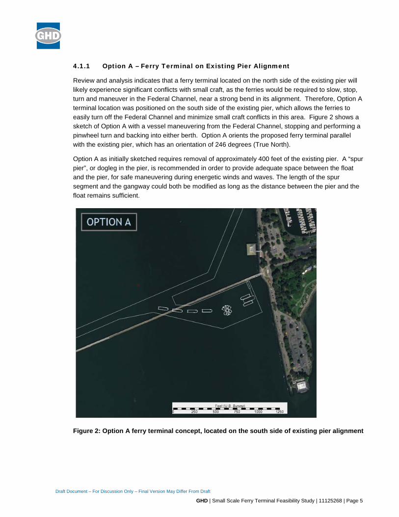
Review and analysis indicates that a ferry terminal located on the north side of the existing pier will likely experience significant conflicts with small craft, as the ferries would be required to slow, stop, turn and maneuver in the Federal Channel, near a strong bend in its alignment. Therefore, Option A terminal location was positioned on the south side of the existing pier, which allows the ferries to easily turn off the Federal Channel and minimize small craft conflicts in this area. Figure 2 shows a sketch of Option A with a vessel maneuvering from the Federal Channel, stopping and performing a pinwheel turn and backing into either berth. Option A orients the proposed ferry terminal parallel with the existing pier, which has an orientation of 246 degrees (True North).
Option A as initially sketched requires removal of approximately 400 feet of the existing pier. A “spur pier”, or dogleg in the pier, is recommended in order to provide adequate space between the float and the pier, for safe maneuvering during energetic winds and waves. The length of the spur segment and the gangway could both be modified as long as the distance between the pier and the float remains sufficient.
Figure 2: Option A ferry terminal concept, located on the south side of existing pier alignment

Draft Document – For Discussion Only – Final Version May Differ From Draft
GHD | Small Scale Ferry Terminal Feasibility Study | 11125268 | Page 6
Figure 3 – Option A Ferry Terminal at Existing Pier Alignment
4.1.2 Option B – Ferry Terminal at South Pier Location
Option B was positioned south of the existing pier, along a new pier alignment, allowing the ferries to easily turn off the Federal Channel and minimize small craft conflicts in this area. Figure 4 shows a sketch of Option B with a vessel maneuvering from the Federal Channel, stopping and performing a pinwheel turn and backing into either berth. Option B orients the proposed ferry terminal parallel with a proposed new pier, which has an orientation of 257 degrees (True North).
Option B also requires removal of approximately 400 feet of the existing pier, and has a very similar “spur pier”, or dogleg in the pier, for safe maneuvering during energetic winds and waves. As with Option A, the length of the spur segment and the gangway could both be modified as long as the distance between the pier and the float remains sufficient.

Draft Document – For Discussion Only – Final Version May Differ From Draft
GHD | Small Scale Ferry Terminal Feasibility Study | 11125268 | Page 7
Figure 4: Option B ferry terminal concept, located at a new south pier location

Draft Document – For Discussion Only – Final Version May Differ From Draft
GHD | Small Scale Ferry Terminal Feasibility Study | 11125268 | Page 8
Figure 5 – Option B Ferry Terminal at New South Pier Location
4.1.3 Ferry Float Alignments
Ferry float alignments were evaluated to determine how closely they coincide with predicted wave directions, to minimize wave loads on the float and wave-induced motions of both the float and the moored vessels. Significant wave heights and peak wave directions were extracted from the Bay-wide wave transformation model at multiple points around the floats for both Option A and B. Figure 6 shows the locations where wave conditions were extracted (top) and a wave rose (bottom) which indicates the incident wave directions and significant wave heights at the point labeled #1076.
Modeling results show that Option A (at existing pier alignment) has slightly better alignment than Option B in terms of wave direction, however both Options are relatively well aligned to the predominant wave directions. The float and vessel orientations were not evaluated relative to wind directions, which should be performed during later phases of design. Design waves and wave protection at the terminal has not been evaluated during this phase of the analysis. The terminal is subject to a stronger wave environment than any other ferry terminal in the Bay Area, and sufficient consideration must be given to its impacts on operations and maintenance.

Draft Document – For Discussion Only – Final Version May Differ From Draft
GHD | Small Scale Ferry Terminal Feasibility Study | 11125268 | Page 9
Figure 6: Wave extraction points near Berkeley Pier Ferry Terminal (top) and wave rose-histogram plot associated with point 1076 (bottom).

Draft Document – For Discussion Only – Final Version May Differ From Draft
GHD | Small Scale Ferry Terminal Feasibility Study | 11125268 | Page 10
Figure 7 – Wave-Rose Histogram
4.2 Conceptual Replacement Pier
GHD reviewed the feasibility of utilizing a 300’ to 500’ long pile-supported pier as access to the ferry terminal. The new pier would replace the existing structure and may include steel and concrete elements and will meet current seismic performance requirements per the current California Building Code (CBC.) The conceptual pier would serve a dual purpose – provide recreational and viewing opportunities for the public and also be used for access to the passenger ferry terminal from landside. The terminal (access ramp, pier, ferry float and gangway) will be a permanent structure with an anticipated service life of 50 years.
Concepts for the dual purpose pier are based on concepts developed in GHD’s Municipal Pier Structural Assessment Report. The new pier can utilize either monopile or dual pile bents, constructed using either steel pipe or precast concrete piles, with cast-in-place concrete pile caps and precast concrete deck panels. Figure 6 below show a partial plan and typical section of the concept pier using a monopile configuration.

Draft Document – For Discussion Only – Final Version May Differ From Draft
GHD | Small Scale Ferry Terminal Feasibility Study | 11125268 | Page 11
Figure 8 – Replacement Pier Concept using Monopile Bents

Draft Document – For Discussion Only – Final Version May Differ From Draft
GHD | Small Scale Ferry Terminal Feasibility Study | 11125268 | Page 12
Figure 9 below shows a partial plan and typical section of the concept pier using two precast piles per bent.
Figure 9 – Replacement Pier Concept using Two Concrete Pile Bents
The pier may include a wind shelter and sun shade structure for the ferry passenger waiting area. A security gate would be located at the entrance to the gangway. There would also be a pass through area for recreational pier users and public to access the remaining areas of the pier.
An approach and ramp will be required at the shore end of the pier to provide secure and safe entry from the land to the recreational pier and ferry terminal access gangway. The new pier will require a higher deck elevation than the existing pier due to anticipated higher water levels in the future. To allow for ADA-access from the landside, it may be necessary to use a fixed steel or concrete ramp, approximately 60 feet long with a maximum 8.33% slope. Pier bents would not be used at the ramp location. The ramp can be supported on the shore by an abutment at the pier approach. Subsurface investigation is required to see if soil improvements are needed at this location to mitigate liquefaction or lateral spreading of soft soil layers during a seismic event. The soil improvements could consist of Deep Soil Mixing (DSM), a technique using grout mixed the in situ soil to create material with higher strength and less vulnerable to vertical or lateral displacement produced by a seismic event.
The ferry float would be located away from the pier alignment at a distance from shore to provide sufficient depth for the ferry vessels and float. The abutment would be located on the shoreline at Seawall Drive and would consist of a concrete abutment supported on steel or concrete piles. The

Draft Document – For Discussion Only – Final Version May Differ From Draft
GHD | Small Scale Ferry Terminal Feasibility Study | 11125268 | Page 13
conceptual pier will consist of a precast or cast-in-place concrete structure (Figure 8 and Figure 9) supported on 36-inch diameter steel piles or 24” square precast piles with a perimeter guardrail.
The finished deck surface will have an elevation of approximately +15.3 feet MLLW. The pier can be partially covered by a weather canopy for ferry passengers and the public. Segment 2 or “spur” can serve as a passenger waiting area, and include benches and educational interpretive signs to enhance the waiting area for ferry passengers. We recommend that the first and second (“spur”) segments of the dual purpose pier be sufficiently wide to allow for two lines of passengers and room for passengers disembarking. Benches may be required by permitting agencies and further limit the usable width. The benches restrict the width of pier making it difficult to queue people boarding and allow passengers to disembark. Benches are not necessary on the pier for boarding passengers. The pier will be kept open to the public at all times (a security gate would be installed at the top of the gangway and closed when the terminal is not in use).
The new pier and ferry terminal, including the landside abutment, pier approach, pile-supported pier and ferry float, should be designed as an "Essential Facility". An "Essential Facility" will remain operational following a Design Earthquake (DE) event. This is a WETA requirement for their San Francisco Bay Area terminals. The seismic performance requirements for an Essential Facility are increased over those for a recreational pier.
GHD recommends that the new pier deck elevation should be constructed at approximately EL+15.3’ MLLW to accommodate future sea level rise. The shoreline grade at both the Option A and Option B locations are approximately EL +10’ MLLW. The pile-supported pier may have a 1:12 sloped ramp to provide a smooth, accessible transition from the shoreline to the pier deck.
Recommendations
The dual purpose pier may have segments partially covered to provide protection from the elements for passengers. The width of conceptual pier segment 1 and the pier “spur” (segment 2) is 18 feet with a clear width of 16 feet to allow 3 rows of passenger queuing, 2 to board and 1 to debark. Benches are not recommended to be placed on the pier spur. The terminal will be designed as an "Essential Facility" and the fixed pier deck elevation should be based on sea level rise predictions for the site.
Security gates can be located at the entry to the spur pier segment or at the access gangway. A gate and security structure at either location can signage and notice area. Ticketing facilities would be provided on the vessels and a commuter Clipper Card reader can also be installed beyond the security gate.
4.3 Conceptual Ferry Float
The ferry float at the conceptual terminal is envisioned to be 135 feet in length and 42 feet wide (beam). Float construction is typically steel or concrete. Steel has been a common choice in San Francisco Bay in the past as the local shipyards generally favor barge fabrication methods. However, more recently concrete floats have been used in greater number as local fabrication facilities become available and concrete construction methods familiar.
A steel float is fabricated similar to standard barge construction using welded steel plates, angles and other steel sections. The ferry float may be fabricated with steel using barge construction or as a

Draft Document – For Discussion Only – Final Version May Differ From Draft
GHD | Small Scale Ferry Terminal Feasibility Study | 11125268 | Page 14
concrete pontoon. WETA has been moving towards a standardized steel float as they have a spare float than can be installed for temporary use during maintenance dredging at their terminals.
The ferry float will serve a number of functions including providing support for the gangway and platforms that will allow passengers access to the ferry vessels. The float is equipped with marine fenders and also provides moorage for the vessels. The float is also intended to support various utilities that serve the vessels and provide safe access for the passengers.
Internal ballast is used to trim the float to adjust for vessel freeboards and for off-center loading on the float, such as the platforms and access gangway load reaction. The float compartments are divided by watertight bulkheads and may be foam–filled to provide buoyancy in case one of the compartments is damaged by vessel or debris impact.
Vertical fenders and mooring cleats are be located around the perimeter of the float to accommodate vessel berthing. The float will be held in position with a preliminary arrangement of four 48-inch diameter steel guide piles and two 54-inch diameter steel fender piles, totaling six piles. The guide piles are attached to the float by collars that allow the float to move up and down with the tide. Ultra high molecular weight (UHMW) pads allow the collars to move along the pile surface without binding.
The fender piles serve as protection to both the float and the vessel should the ferry lose navigation nearing the float. “Donut fenders” (fenders that move up and down on the vertical fender piles) are located near the float for additional protection against vessel impact.
Stability analysis will be conducted where the rectangular float prism is reviewed and the metacenter (GM) calculated to determine if the floating body is stable. The difference in height between the float’s center of gravity and GM is a measure of stability of a floating body. High GM values are more stable than low values.
A gangway will provide access from the pier spur to the float. The float end of the gangway will have wheels or guides to allow backward and forward movement of the float with varying tide levels and wave motions. The pier end of the gangway would be designed to allow movement of the float in the lateral direction. The gangway is hinged at the pier connection to allow rotation with tide levels.
4.3.1 Float Design
Steel floats are typically fabricated in a similar manner to material and equipment barges, with bulkhead frames used along with stiffened keel, hull and deck plates. Steel floats are generally simple to modify and attach elements to (fenders, mooring cleats, platform supports, etc.) by welding. The floats can also be reconfigured easily. Steel floats are susceptible to corrosion in the marine environment and must be coated with a high-build marine epoxy and have a passive cathodic protection system consisting of anodes attached to the steel hull. A steel float will need to be removed from the water every five to 10 years for cleaning and recoating and replacement of anodes. Dive inspections can be conducted to determine condition of the float and when dry dock service will be required. A means to temporarily suspend the gangway may also need to be provided. This operation requires that service be disrupted and that a temporary float be available to continue ferry service. This represents a significant maintenance cost over the service life of the facility.

Draft Document – For Discussion Only – Final Version May Differ From Draft
GHD | Small Scale Ferry Terminal Feasibility Study | 11125268 | Page 15
Preliminary analysis has shown that the draft of a steel float at the Berkeley Ferry Terminal site would be approximately six feet. With three feet of freeboard this produces a total float depth of 9 to 10 feet. This would require slightly less dredge depth at the Berkeley Terminal sites than the concrete float.
Steel float hull construction offers the following advantages:
• Expected to be lower cost than concrete for moderate to smaller size floats and limited order quantities
• Easier to modify
• Conventional shipyard methods for construction and maintenance apply (bulk cargo barges, etc.)
• Damage to hull is easier to repair
• Longer track record of steel floats and barges being fabricated locally
4.3.2 Recommended Float Option
Because of the relative ease of barge construction, a steel superstructure on a low-freeboard (approximately 3 foot) steel float as shown on Figure 10 below may be the preferred configuration. The superstructure can be modified in the future as vessels and boarding freeboards change over time and the steel float structure can accommodate modifications (adding mooring cleats and fenders) and a long service life will be provided assuming periodic inspection and dry dock maintenance (marine growth removal, anode replacement and recoating.) Removal of the float from the terminal for dry docking will cause ferry schedule disruptions if a temporary float is not installed.

Draft Document – For Discussion Only – Final Version May Differ From Draft
GHD | Small Scale Ferry Terminal Feasibility Study | 11125268 | Page 16
Figure 10 – Conceptual Ferry Float Section
Future maintenance costs will be required for towing the steel float from the terminal, dry-docking, coating removal, recoating and anode replacement. We estimate that a steel float will require this service at approximately five to 10 year intervals.
For construction of the ferry terminal, fabrication of the steel float and gangway are typically completed off-site. The pile-supported pier, abutment and ramp would be completed before the arrival of the float and gangway. With the pier completed, the float would be brought in and located in position. This would involve installing the guide piles for the float, possibly using the collars as pile guides and the dolphin fender piles at the end of the float, as the crane barge and equipment will be at the site. Once the float is in position, the gangway is then be placed using the crane. Utilities would then be connected. The in-water work (float installation with piles and gangway) will be completed within one environmental work season (typically June 1st to November 30th). Other work on the pier or float deck can be completed outside of the work window.
4.3.3 Security Gate
The security gate can be provided at either the gangway end of segment 2 (“spur”) or at the start of segment 2. This can be reviewed with WETA. Placing the gate at the start of segment 2 will allow this portion of the pier to provide cover for queuing passengers and maintaining public access to segment 3 and the end of the pier. The terminal will be unmanned and the gate will be opened and closed by the ferry boat crew. A security alarm and camera may be provided at the gate. The gate can be located a short distance, approximately 10 feet from the top of the gangway. The area behind the gate on pier segment 2 will provide space for Clipper reader machines.

Draft Document – For Discussion Only – Final Version May Differ From Draft
GHD | Small Scale Ferry Terminal Feasibility Study | 11125268 | Page 17
4.4 Conceptual Ferry Terminal Gangway
Over the past several years, concerns regarding the impact of sea level rise (SLR) due to climate change require that new fixed piers be constructed at increasingly higher elevations. This requires longer gangways to allow passenger ferry and other vessel boarding at very low tidal conditions, to remain within the 1:12 slope limits required for conformance with Section 4.8 (Ramps) of the Americans with Disabilities Act Design Guidelines (ADADG) and the California Building Code (CBC), Chapter 11.
While the ADADG and CBC Section 11V-1003, provide guidance for Recreational Boating Facilities, they do not specifically cover passenger vessels. The United States Access Board has developed proposed accessibility guidelines for passenger vessels which is available at the link below.
https://www.access-board.gov/guidelines-and-standards/transportation/passenger-vessels/proposed- accessibility-guidelines/1386-chapter-v4-onboard-accessible-routes-and-accessible-passenger-boarding- systems
Section 4.10 of the proposed guidelines covers gangways but does not include exceptions for allowable exceedance of the 1:12 gangway slope limit at extreme tidal conditions. The proposed guidelines do have an exception for gangways exceeding 120'. Paul notes that the scoping requirements in Section 208.1 indicate that accessible boarding systems need to be installed when required by the Department of Transportation (DOT) or the Department of Justice. According to Paul, however, the DOT has not developed rules and will not under the current administration, due to restrictions on rule making. It was anticipated that the DOT rules would look at the 'thru-put' and scale of the facility, as well as operational items such as assistance by crew members.
4.4.1 Water Elevations
Water Level Elevations in the design are based on the tidal information for Berkeley, CA (NOAA Station ID 9414816), for the tidal epoch 1983-2001, as shown in the Figure 4-1 below, excerpted from the Berkeley Pier Structural Assessment Study. The project datum is Mean Lower Low Water (MLLW).
Level MLLW Elevation (feet)
Highest Astronomical Tide (HAT)
7.6
Mean Higher High Water (MHHW)
6.1
Mean Lower Low Water (MLLW)
0.0

Draft Document – For Discussion Only – Final Version May Differ From Draft
GHD | Small Scale Ferry Terminal Feasibility Study | 11125268 | Page 18
Lowest Astronomical Tide (LAT)
-2.1
4.4.2 Pier Deck Elevation and Float Freeboard
Fixed Pier Elevation: Base Flood Elevation and SLR projections for the Berkeley Pier were reviewed by GHD and it was estimated that the future maximum water level for design will be +13.33’ MLLW. The pier deck is estimated to be +15’-3” MLLW.
Float Freeboard: Passenger loading onto ferries occurs via a Passenger Float that maintains a constant freeboard (height above the adjacent water level). The Water Emergency Transportation Authority (WETA) is working to standardize the size and layout of their Passenger Floats. The standard WETA steel float, Passenger Float will most likely be used for the Berkeley Ferry Terminal. The float will accommodate two ferry vessels, is 135’ long by 42’ wide, and is a minimum of 6’-4” deep. The float itself has a freeboard of 3’ and a raised ramping walkway system that accommodates freeboards of a variety of vessels. The freeboard of the walkway at the bottom of the gangway is typically 8’- 5” (101”) above the waterline.
4.4.3 Gangway Length at Low Water Levels
Tide Condition
Elevation Top of
Gangway
Waterline Freeboard at Bottom
of Gangway
Height Difference
ADA Gangway Length to Achieve
1:12 Slope
(feet) (feet) (feet) (feet) (feet)
Mean Lower Low Water
(MLLW)
15.25 0.0 8.416 6.834 82.0
Lowest Astronomical Tide (LAT)
15.25 -2.1 6.316 8.934 107.2
4.4.4 Gangway Length Evaluation
In the absence of clear federal guidelines allowing the installation of a gangway with a slope exceeding the 1:12 maximum slope requirement at extreme low water levels, the installation of a 110’ long gangway for the Berkeley Ferry Terminal appears to be appropriate.
At high water conditions, the chart below indicates that the slope of the gangway would be essentially flat at high water conditions.

Draft Document – For Discussion Only – Final Version May Differ From Draft
GHD | Small Scale Ferry Terminal Feasibility Study | 11125268 | Page 19
TIDE CONDITIONS
Elevation-Top of
Gangway
(feet)
Waterline
(feet)
Freeboard at bottom of Gangway
(feet)
Height
Difference
(feet)
Gangway Slope with 110' Long Gangway
(feet)
Mean Higher-High Water (MHHW)
15.25 6.1 14.516 0.734 0.7%
Downwards
Highest Astronomical Tide (HAT)
15.25 7.6 16.016 -
0.766 -0.7%
Upwards
5. Preliminary Dredging Design and Sedimentation Rates
5.1 Site Coastal Conditions
Coastal conditions analysis was performed to evaluate existing depths at the site, potential navigation channel and berth sedimentation, conditions which affect safe navigation, and evaluate terminal float alignments. Site coastal conditions of interest include bathymetry and sedimentation, winds, wind-waves, and tides. Tidal currents are generally negligible at the site.
5.2 Site Conditions – Bathymetry and Sedimentation
Recent hydrographic surveys as well as previous hydrographic surveys were compiled and analyzed to assess the depths surrounding the proposed terminal locations, and historical/current patterns and rates of sedimentation. The available hydrographic surveys near the project site include the following:
• May 2018 multibeam (eTrac)
• August 2007 single beam (United States Army Corp of Engineers)
• April 2007 single beam (Coast and Harbor Engineering)
• October 1978 to April 1979 single beam (NOAA)
Figure 11 to Figure 13 show the three primary hydrographic survey datasets utilized in the sedimentation analysis. The black dotted line shows the extents of the Berkeley Pier including the remnants of the pier which once extended over 3 miles into the Bay. Depths range from 5 to 6 feet (MLLW) to more than 17 feet (MLLW) at the pier’s offshore extent, with flat slopes in the range of 1000H:1V. Note that the 2007 hydrographic survey is a combination of a USACE 2007 survey and Coast & Harbor Engineering (2007) survey.

Draft Document – For Discussion Only – Final Version May Differ From Draft
GHD | Small Scale Ferry Terminal Feasibility Study | 11125268 | Page 20
Figure 11: May 2018 multibeam hydrographic survey at Berkeley Pier (eTrac)
Figure 12: Combined 2007 single beam hydrographic survey at Berkeley Pier (USACE and Coast & Harbor Engineering)

Draft Document – For Discussion Only – Final Version May Differ From Draft
GHD | Small Scale Ferry Terminal Feasibility Study | 11125268 | Page 21
Figure 13:1978-1979 single beam hydrographic survey at Berkeley Pier (NOAA)
Figure 14 shows measured depth changes from 1979 to present, and Figure 15 shows measured depth changes in the more recent period 2007 to 2018. In both survey comparisons, changes are minimal on an annual basis, and generally within the accuracy feasible in the analysis based on single-beam survey data. The analysis does show clearly, however, that sedimentation is minimal, but present, in the shallower portion of the navigation channel. A general sedimentation rate of 0.1 feet per year is recommended for consideration of navigation channel and berth dredging options.

Draft Document – For Discussion Only – Final Version May Differ From Draft
GHD | Small Scale Ferry Terminal Feasibility Study | 11125268 | Page 22
Figure 14: Measured sedimentation, 1979 to 2018
Figure 15: Measured sedimentation, 2007 to 2018
Draft Document – For Discussion Only – Final Version May Differ From Draft
GHD | Small Scale Ferry Terminal Feasibility Study | 11125268 | Page 23
5.3 Preliminary Dredging Volumes
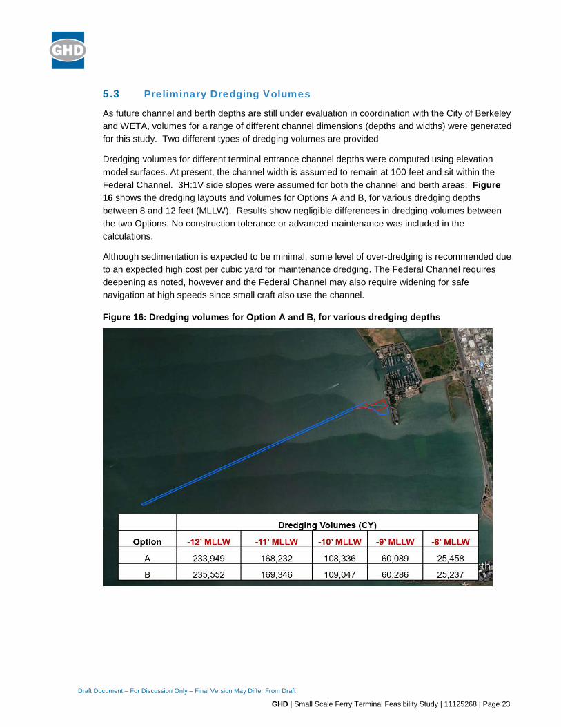
As future channel and berth depths are still under evaluation in coordination with the City of Berkeley and WETA, volumes for a range of different channel dimensions (depths and widths) were generated for this study. Two different types of dredging volumes are provided
Dredging volumes for different terminal entrance channel depths were computed using elevation model surfaces. At present, the channel width is assumed to remain at 100 feet and sit within the Federal Channel. 3H:1V side slopes were assumed for both the channel and berth areas. Figure 16 shows the dredging layouts and volumes for Options A and B, for various dredging depths between 8 and 12 feet (MLLW). Results show negligible differences in dredging volumes between the two Options. No construction tolerance or advanced maintenance was included in the calculations.
Although sedimentation is expected to be minimal, some level of over-dredging is recommended due to an expected high cost per cubic yard for maintenance dredging. The Federal Channel requires deepening as noted, however and the Federal Channel may also require widening for safe navigation at high speeds since small craft also use the channel.
Figure 16: Dredging volumes for Option A and B, for various dredging depths

Draft Document – For Discussion Only – Final Version May Differ From Draft
GHD | Small Scale Ferry Terminal Feasibility Study | 11125268 | Page 24
5.4 Tides
Tides at the project site were evaluated using predicted NOAA Tide Station 9414816 at Berkeley. Table 1 shows the tidal datum information for the Berkeley Station, including the lowest tides predicted during the two-year typical conditions period evaluated here (2013-2014). Analysis of the tidal record indicates that negative tides affecting underkeel clearance occur approximate 5% of the time at Berkeley.
Table 1: Tidal Datum Information for Berkeley (NOAA Station 9414816)
Datum Elevation (ft, MLLW)
Mean Higher-High Water (MHHW) 6.10
Mean High Water (MHW) 5.49
Mean Tide Level (MTL) 3.31
Mean Sea Level (MSL) 3.28
Mean Diurnal Tide Level (DTL) 3.05
Mean Low Water (MLW) 1.14
North American Vertical Datum (NAVD88) -0.13
Mean Lower Low Water (MLLW) 0.00
5.5 Wind-Wave Environment
Wind-waves were predicted at the site using a Bay-wide application of the wind-wave growth and transformation model SWAN (Delft University of Technology 2012). Waves were predicted for the entire 2-year period 2013 and 2014, at hourly intervals, using wind speed, wind direction and tide as inputs. Wind records were taken from NOAA Alameda Station (9414750). Results of the SWAN model included wave characteristics (significant wave height, peak wave direction, and peak wave period) along the channel alignment and in the berthing areas. Figure 17 shows the results of SWAN Bay-wide modeling simulation during Westerly wind conditions, as an example. Figure 18 shows time histories of wave and tide conditions that were used for the ferry underkeel evaluation, which were extracted at the worst-case location in the navigation channel near the project site.

Draft Document – For Discussion Only – Final Version May Differ From Draft
GHD | Small Scale Ferry Terminal Feasibility Study | 11125268 | Page 25
Figure 17: Predicted significant wave heights during 12-mph winds from due West (270 degrees True North), as an example
Figure 18: Wave and tide conditions during two-year period (2013 and 2014), extracted at most energetic location along navigation channel
Draft Document – For Discussion Only – Final Version May Differ From Draft
GHD | Small Scale Ferry Terminal Feasibility Study | 11125268 | Page 26
6. Ferry Vessel Type, Navigation and Operations Evaluation
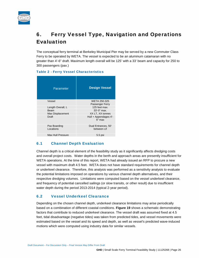
The conceptual ferry terminal at Berkeley Municipal Pier may be served by a new Commuter Class Ferry to be operated by WETA. The vessel is expected to be an aluminum catamaran with no greater than 4’-6” draft. Maximum length overall will be 125’ with a 33’ beam and capacity for 250 to 300 passengers (pax.)
Table 2 - Ferry Vessel Characteristics
Parameter
Design Vessel
Vessel WETA 250-325 Passenger Ferry
Length Overall, L 125 feet max. Beam 33’-0” max. Max Displacement XX LT, XX tonnes Draft Hull + Appendages 4’-
6” max
Pax Boarding Locations
Dual Entrances, 50’ between c/l
Max Hull Pressure 5.5 psi
6.1 Channel Depth Evaluation
Channel depth is a critical element of the feasibility study as it significantly affects dredging costs and overall project costs. Water depths in the berth and approach areas are presently insufficient for WETA operations. At the time of this report, WETA had already issued an RFP to procure a new vessel with maximum draft 4.5 feet. WETA does not have standard requirements for channel depth or underkeel clearance. Therefore, this analysis was performed as a sensitivity analysis to evaluate the potential limitations imposed on operations by various channel depth alternatives, and their respective dredging volumes. Limitations were computed based on the vessel underkeel clearance, and frequency of potential cancelled sailings (or slow transits, or other result) due to insufficient water depth during the period 2013-2014 (typical 2-year period).
6.2 Vessel Underkeel Clearance
Depending on the chosen channel depth, underkeel clearance limitations may arise periodically based on a combination of different coastal conditions. Figure 19 shows a schematic demonstrating factors that contribute to reduced underkeel clearance. The vessel draft was assumed fixed at 4.5 feet, tidal disadvantage (negative tides) was taken from predicted tides, and vessel movements were estimated based on the vessel and its speed and depth, as well as vessel’s predicted wave-induced motions which were computed using industry data for similar vessels.

Draft Document – For Discussion Only – Final Version May Differ From Draft
GHD | Small Scale Ferry Terminal Feasibility Study | 11125268 | Page 27
Figure 19: Factors affecting underkeel clearance
Vessel motions most strongly affecting underkeel clearance include squat, heave, and pitch. Roll effects in the navigation channel are expected to be relatively low since the wave directions at the site are consistently aligned with the channel. Squat effects cause vessels to sit lower in the water while underway at higher speed in relatively shallow water. For these types of vessels, however, literature review indicates that squat is not expected to be a significant contributor to reduced underkeel clearance. Heave (vertical motion of the entire vessel) and pitch (forward/aft rotation about the center of the vessel) are induced by waves and must be considered. Trim effects were unknown and were not included at this time.
Vessel motions in waves are described by Response Amplitude Operators (RAOs). RAOs for a similar catamaran ferry were taken for literature, including a similar vessel moving at 30 knots in head seas (normal to wave crests, similar to Berkeley). Figure 20 shows the RAO curves which include dimensionless motion as a function of wave frequency. These curves were used as lookup tables to compute wave-induced motions during each hourly record in the 2013-2014 period, based on the maximum wave height (converted from significant wave height) and peak wave period.

Draft Document – For Discussion Only – Final Version May Differ From Draft
GHD | Small Scale Ferry Terminal Feasibility Study | 11125268 | Page 28
Figure 20: Response Amplitude Operators (RAOs) for Heave (left) and Pitch (right) for catamaran ferry at 30 knots in head seas (Lin et al 2017).
6.3 Channel Evaluation Results
Using the predicted coastal conditions and a range of assumed channel depths, underkeel clearances were calculated for the entire hourly record covering two years (2013-2014). Table 5 shows the calculated hourly underkeel clearances during the two-year period, for channel depths ranging from 9.0 to 7.5 feet (MLLW), at 0.5-feet intervals. The red line on the plots represents an underkeel clearance of 2 feet, for reference. Error! Reference source not found. summarizes the number of hourly records within which the underkeel clearance was less than 1, 2 or 3 feet for each of these channel depths between 7.5 and 9.0 feet (MLLW).
Table 3 - Annual Hourly Instance for Underkeel Clearance Less than 1 to 3 feetfor Channel Depths 7.5 to 9.0 feet (MLLW)
Underkeel Clearance
[ft] 7.5 ft MLLW 8.0 ft MLLW 8.5 ft MLLW 9.0 ft
MLLW
1 1 0 0 0
2 39 13 1 0
3 210 95 39 13
The number of hourly instances when underkeel clearance would have been less than 1, 2 or 3 feet represent a small portion of the time, considering 8,760 hours in a year. These occurrences of low underkeel clearance were further investigated to determine when during the day they occur, and likely impacts to operations. Figure 21 shows a histogram of wind speeds greater than 10 mph for different times of the day, and predictably the data show that stronger winds occur during the afternoon. However, low tides tend to control underkeel clearance more strongly than winds or waves. Figure 22 shows a histogram demonstrating the times during the day at which underkeel clearances less than 3 feet occur, for channel depth 7.5 feet (MLLW) as an example. Analysis indicates that low tides generate the majority of the hourly instances of low underkeel clearance.

Draft Document – For Discussion Only – Final Version May Differ From Draft
GHD | Small Scale Ferry Terminal Feasibility Study | 11125268 | Page 29
The negative tides (those below MLLW) tend to occur most often in the 5-6am and 5-6pm time frames, which are likely to affect early morning and evening commutes when ferry service is likely to be concentrated. Therefore, any occurrences of low underkeel clearance should be assumed to coincide with heavy operations. Figure 21: Daily (hour by hour) distribution of wind speeds greater than 10 mph

Draft Document – For Discussion Only – Final Version May Differ From Draft
GHD | Small Scale Ferry Terminal Feasibility Study | 11125268 | Page 30
Figure 22: Daily (hour by hour) distribution of underkeel clearances less than 3 feet for channel depth 7.5 feet (MLLW)
7. Anticipated Permits and Approvals
Resource agency review and permitting for a replacement pier and ferry terminal are expected to include the City of Berkeley, San Francisco Bay Regional Water Quality Control Board, U.S. Army Corps of Engineers, U.S. Fish and Wildlife Service, National Marine Fisheries Service, California Department of Fish and Wildlife, San Francisco Bay Conservation and Development Commission (BCDC), and Dredge Material Management Office (DMMO.)
The pier and ferry terminal design will also need to be coordinated with other agencies with jurisdiction over and expertise in areas along the waterfront, including the San Francisco Bay Conservation and Development Commission (BCDC), the San Francisco Bay Regional Water Quality Control Board (RWQCB), the U.S. Army Corps of Engineers (USACE), and the U.S. Fish and Wildlife Service (USFWS). In order to provide safe navigational approaches and maneuvering to the proposal terminal locations, the project will require dredging of the Bay mudline. All material proposed to be dredged will need to be characterized and will be disposed at permitted disposal sites, pursuant to applicable regulations and the Dredged Material Management Office (DMMO) determination of suitability for dredge material disposal for the project. The project will be designed to address sea-level rise based on a design life-span of approximately 50 years.
Required Permits and Approvals
The anticipated consultations, approvals, and permits are listed in Table 4 below.

Draft Document – For Discussion Only – Final Version May Differ From Draft
GHD | Small Scale Ferry Terminal Feasibility Study | 11125268 | Page 31
Table 4 - Anticipated Project Permits and Approvals
Project Activity Type of
Permit/Authority
Local Agency
City of Berkeley Development of replacement recreational pier and new ferry terminal
• Demolition Permit, Design Review, Use Permit, and Building Permits • Approval of long-term lease for construction and operation of new facilities within the city
State and Federal Agencies
San Francisco Bay Conservation and Development Commission
Development within 100 feet from San Francisco Bay shoreline and placement of fill within San Francisco Bay
• McAteer-Petris Act • Administrative or Major Permit • Federal Consistency Certification, including Design Review
Regional Water Quality Control Board, San Francisco Bay Region
Impacts on waters of the state and stormwater discharge during construction
• Clean Water Act Section 402 • Clean Water Act Section 401 • Water Quality Certification • Porter-Cologne Water Quality Control Act • Waste Discharge Requirements
U.S. Army Corps of Engineers
Discharge of dredged or fill material into wetlands or other waters of the U.S. and placement of structures in navigable waters
• Clean Water Act Section 404 • Rivers and Harbors Act Section 10 • Nationwide Permit (NW6)
U.S. Fish and Wildlife Service
Potential impacts on federally listed species
• Federal Endangered Species Act Section 7 • Biological Opinion

Draft Document – For Discussion Only – Final Version May Differ From Draft
GHD | Small Scale Ferry Terminal Feasibility Study | 11125268 | Page 32
National Marine Fisheries Service
Potential impacts on federally listed marine species and essential fish habitat
• Federal Endangered Species Act Section 7 • Biological Opinion • Magnuson-Stevens Fishery Conservation and Management Act • Essential Fish Habitat Recommendations • Marine Mammal Protection Act
U.S. Environmental Protection Agency Construction Activities Review of soil
management plan and other work plans, as necessary
Department of Toxic Substances Control Construction activities Review of soil
management plan and other work plans, as necessary
8. Conclusions and Recommendations for Further Study
8.1 Preliminary Conclusions
The following conclusions are being provided as a result of the ferry terminal feasibility study:
• A new pile-supported pier is suitable to serve both public recreational use and as access for a passenger ferry terminal
• Rehabilitation of the existing pier structure is not recommended due to extensive work and cost required to provide seismic performance required for an Essential Facility needed for a ferry terminal and to provide an appropriate service life prior to future repairs are needed
• Two ferry terminal options have been developed for this study, either option appears suitable.
• A “spur” pier segment is recommended for access to ferry float, otherwise ferry berth is too close to pier. Spur length versus gangway length can be varied to suit the ferry berth size.
• Sedimentation at both proposed terminal locations is minimal. Over-dredging would be recommended due to high cost per cubic yard for maintenance dredging.
• Waves and wave protection at the terminal have not been evaluated, however these efforts are planned for evaluation during further efforts. The terminal is subject to a stronger wave environment than any other ferry terminal in the Bay Area, and sufficient consideration must be given to its impacts on operations and maintenance.
• Vessel under keel clearance requirements will require discussion with WETA, however at >30 knots with 250 pax on board, 2’ under keel clearance is likely near the minimum.
• The Federal Channel likely requires deepening in any case, and may require widening for safety.

Draft Document – For Discussion Only – Final Version May Differ From Draft
GHD | Small Scale Ferry Terminal Feasibility Study | 11125268 | Page 33
• Design of the pier and ferry terminal will conform to the current Americans with Disabilities Act (ADA) Standards for Accessible Design.
• A rough order magnitude construction cost for the pier approach, landside improvements, dual purpose pier, ferry terminal and dredging required for navigation is $26.2M. A summary of the estimate along with assumptions is provided in Appendix D.
8.2 Recommendations for Further Study
The following project elements are recommended for further study and to assist with developing the project scope for preliminary and final design.
8.2.1 Develop Parking Alternatives
1. Obtain ridership projections and confirm parking criteria with WETA.
2. Conduct site visit to examine existing conditions.
3. HS Lordship’s lot - develop plan showing potential densification of parking.
4. New Lot (South side of University Ave. at Marina Blvd.) - obtain information from the City on lot boundaries, restrictions (easements, etc.), and proposed traffic loop.
5. Layout initial concept parking plan for new lot.
6. Explore densification options for other existing lots.
7. Review ADA path of travel from parking areas to entrance of pier/ferry terminal. Develop site plan showing existing features with elevation data and accessible routes noted.
8.2.2 Topographic Study
1. Perform a topographic survey of parking areas and other landside features that may be included in the conceptual ferry terminal alternatives.
8.2.3 Review Parking Layouts
1. Update parking layouts to incorporate City feedback.
8.2.4 Review of Landside Utilities
Review of utilities required on the shoreside to support the pier and ferry terminal. Utilities are expected to include water, electrical, telecommunication. Stormwater management and requirements should also be reviewed for the project site.
8.2.5 Develop Initial Concept Site Plans
1. Develop site circulation diagrams for bus, rideshare, pedestrian and bike circulation.
2. Coordinate with City on location of Bay Trail.
3. Confirm desired site amenities with City (bicycle lockers, bicycle racks, benches, trash receptacles, toilet facilities, etc.)
4. Develop initial concept site plans for the two pier and terminal locations.

Draft Document – For Discussion Only – Final Version May Differ From Draft
GHD | Small Scale Ferry Terminal Feasibility Study | 11125268 | Page 34
8.2.6 Review initial concept site plans with City and WETA
1. Identify preferred location for replacement pier (in existing location or adjacent to HS Lordship’s parking lot.)
2. Identify updates needed to concept site layout.
8.2.7 Refine preferred site plan
1. Incorporate updates identified from City and WETA reviews.
2. Further develop site circulation and site amenities.
3. Develop concept site lighting plan.
4. Develop concept landscaping plan.
8.2.8 Review preferred site plan with BCDC, City, WETA and Public
1. Update plan to reflect input received.
2. Solicit public input as directed by City.
3. Develop cost estimate.
8.2.9 Perform wave protection assessment
1. Perform wave protection assessment of the two terminal locations consisting of the following subtasks:
a. Summary of coastal conditions and statistics from previous work.
b. Perform nearshore wave transformation analysis using numerical modeling tools to provide accurate conditions for development of waves adjacent to the pier and ferry terminal. Wave protection alternatives will consist of breakwaters (bulkhead, rock, floating). Wave transmission and transformation modeling will be performed using 2D modeling tools (SWASH, Mike21BW, or other). Results will include maps of wave heights, statistics and other information.
c. Provide technical memorandum containing study results and recommendations.
8.2.10 Preliminary geotechnical engineering assessment
Perform an initial geotechnical review using record information to inform the conceptual design of the pier and ferry terminal.
The initial review is expected to include the following tasks:
1. Review of available geologic maps and geotechnical reports to assess the geologic conditions at the site.
2. Develop preliminary geotechnical parameters for conceptual design of waterside and landside project elements.
3. Provide a geotechnical memorandum presenting findings and recommendation for conceptual design of the pier and terminal improvements.

Draft Document – For Discussion Only – Final Version May Differ From Draft
GHD | Small Scale Ferry Terminal Feasibility Study | 11125268 | Page 35
A geotechnical investigation consisting of subsurface investigation and testing will be conducted at the selected pier and terminal location prior to preliminary and final design. The information will be needed to estimate pier pile and terminal float guide pile capacities, pavement design and review lateral spreading and vertical displacement at the shoreside pier approach due to an earthquake.
8.2.11 Refine dual purpose pier concepts
1. The first segment of the pier is expected to include the WETA ferry terminal and the second pier segment used for public recreation and use. A security gate and fence will be required at the ferry terminal entrance.
2. Incorporate comments and updates obtained from City, WETA and stakeholder review.
3. Further develop pier and ferry terminal features and elements. Advance two alternatives to concept design level.
8.2.12 Develop preliminary cost estimates
Develop planning-level cost estimates for the conceptual pier, ferry terminal, dredging and site improvement alternatives. The estimate summary will contain a breakdown of the larger project elements along with construction quantities and unit costs.

Draft Document – For Discussion Only – Final Version May Differ From Draft
GHD | Small Scale Ferry Terminal Feasibility Study | 11125268
Appendix A


crlewis
Callout
SEGMENT 1
crlewis
Callout
SEGMENT 2 ("SPUR")
crlewis
Callout
SEGMENT 3

crlewis
Callout
SEGMENT 1
crlewis
Callout
SEGMENT 2 ("SPUR")
crlewis
Callout
SEGMENT 3

FIGUREFLOAT TRANSVERSE SECTION
FENDER
3'-0" FREEBOARD
ADJUSTABLE RAMP (TYPICAL)
DECK PLATE
42'-0"
8'-0"
FIXED RAMP PLATFORMSUPERSTRUCTURE
48"Ø GUIDE PILE (TYPICAL)
HULL PLATE
KEEL PLATE TRANSVERSE FRAME (TYPICAL)
MLLW
9'-6"
DateReport No.Project No.
Filename: \\ghdnet\ghd\US\San Francisco\Projects\111\11125268 Berkeley Municipal Pier Assessment\06-CAD\Sheets\11125268 FLOAT SECTION FIGURE.dwgPlot Date: 10 September 2018 - 8:48 AM
CITY OF BERKELEY
SMALL-SCALE FERRY TERMINAL FEASIBILITYSTUDY AT BERKELEY MUNICIPAL PIER
11125268-SEPT 2018
Source:
GANGWAY
STEEL FERRY FLOAT
LONGITUDINALBULKHEAD

Draft Document – For Discussion Only – Final Version May Differ From Draft
GHD | Small Scale Ferry Terminal Feasibility Study | 11125268
Appendix B

381291 1 A https://mottmac.sharepoint.com/teams/pj-c3832/Berkeley Ferry Terminal/4 - Technical
Docs/2018-09-06 Berkeley Ferry Terminal Feasibility - Working Draft v0.docx Mott MacDonald
Mott MacDonald 155 Montgomery Street Suite 1400 San Francisco CA 94104 United States of America T +1 (415) 968 3495 F +1 (415) 773 2396 mottmac.com
WORKING DRAFT Berkeley Pier Ferry Terminal Feasibility Study Coastal Engineering Analysis and Concept Design
September 6, 2018


Mott MacDonald | Berkeley Pier Ferry Terminal Feasibility Study Coastal Engineering Analysis and Concept Design
381291 | 1 | A | September 6, 2018 https://mottmac.sharepoint.com/teams/pj-c3832/Berkeley Ferry Terminal/4 - Technical Docs/2018-09-06 Berkeley Ferry Terminal Feasibility - Working Draft v0.docx
Issue and revision record
Revision Date Originator Checker Approver Description 0 9/5/18 Scott Fenical Frank Salcedo Scott Fenical Draft for client review
Document reference: 381291 | 1 | A Information class: Standard
This document is issued for the party which commissioned it and for specific purposes connected with the above-captioned project only. It should not be relied upon by any other party or used for any other purpose.
We accept no responsibility for the consequences of this document being relied upon by any other party, or being used for any other purpose, or containing any error or omission which is due to an error or omission in data supplied to us by other parties.
This document contains confidential information and proprietary intellectual property. It should not be shown to other parties without consent from us and from the party which commissioned it.
This R eport has been prepar ed sol el y for use by the party which commissi oned it (the 'Client') in connection wi th the capti oned pr oject. It shoul d not be used for any other purpose. N o person other than the Client or any party who has expr essl y agreed terms of reli ance with us (the 'Recipi ent(s)') may r el y on the content, infor mation or any views expr essed in the R eport . This R eport is confi denti al and contains pr opri etary intell ectual pr operty and we accept no duty of car e, r esponsibility or li ability to any other recipi ent of this R eport . N o repr esentati on, warranty or undertaki ng, express or i mplied, is made and no responsi bility or liability is accepted by us to any party other than the Client or any Reci pient(s), as to the accuracy or completeness of the i nfor mati on contai ned i n this R eport . For the avoi dance of doubt thi s Report does not i n any way pur port to i nclude any legal, insurance or fi nanci al advice or opi nion.

Mott MacDonald | Berkeley Pier Ferry Terminal Feasibility Study Coastal Engineering Analysis and Concept Design
381291 | 1 | A | September 6, 2018 https://mottmac.sharepoint.com/teams/pj-c3832/Berkeley Ferry Terminal/4 - Technical Docs/2018-09-06 Berkeley Ferry Terminal Feasibility - Working Draft v0.docx
Contents
Executive Summary 1
1 Introduction 2
2 Site Coastal Conditions 3 2.1 General 3 2.2 Bathymetry 3 2.3 Sedimentation 5 2.4 Tides 7 2.5 Wind-Waves 7
3 Channel Depth Evaluation 9 3.1 Approach 9 3.2 Underkeel Clearance Calculation 9 3.3 Underkeel Clearance Results 10
4 Terminal Concepts 14 4.1 Terminal Concept Criteria 14 4.2 Proposed Terminal Design Concepts 14
4.2.1 Option A - Terminal on Existing (Rehabilitated) Pier 14 4.2.2 Option B - Terminal on New Southern Pier 15 4.2.3 Float Alignments 16
5 Dredging Volumes 18 5.1 General 18 5.2 Dredging Volume Calculations 18

Mott MacDonald | Berkeley Pier Ferry Terminal Feasibility Study Coastal Engineering Analysis and Concept Design 1
381291 | 1 | A | September 6, 2018 https://mottmac.sharepoint.com/teams/pj-c3832/Berkeley Ferry Terminal/4 - Technical Docs/2018-09-06 Berkeley Ferry Terminal Feasibility - Working Draft v0.docx
Executive Summary
Analysis and feasibility-level design efforts were performed by Mott MacDonald (MM) upon request from GHD and the City of Berkeley, CA for the Berkeley Pier Ferry Terminal Feasibility Study. The purpose of the analysis was to develop feasibility-level options for a navigation channel and berth/terminal, to be developed in combination with Berkeley Municipal Pier rehabilitation or replacement. As part of the analysis, MM evaluated site coastal conditions, sedimentation, channel and berth depth alternatives and their respective operational limitations, and generated navigation channel/berth layouts and dredging volumes.
Site coastal conditions are more energetic than any other ferry terminal in San Francisco Bay. The site is shallow, with depths less than 10 feet for several miles offshore. Wave conditions were generated for a 2-year period using a Bay-wide wind-wave growth and transformation model, and tidal conditions were taken from NOAA predictions. Existing depths were evaluated using a new hydrographic survey (eTrac 2018), and sedimentation was investigated through comparison with previous hydrographic surveys from 1979 to present. Analysis indicates that sedimentation near the project site (landward end of the pier) from 1979 to present is less than 1 inch per year on average.
A range of depths for the navigation channel and berth area were investigated, using the expected underkeel clearance during two years of typical conditions as a criterion for suitability to provide safe and efficient operations. Underkeel clearance was evaluated based on the draft of the proposed low-draft ferry, wave conditions, expected wave-induced motions, and tides. Results indicates that tidal disadvantage (negative tides) generate the highest level of potential downtime caused by insufficient water depth, however wave-induced motions also play a role.
The initial ferry terminal alternatives were assumed to utilize the majority of the Federal Channel (US Army Corps of Engineers) which provides access to the Berkeley Marina. The Federal Channel is a 100-ft wide channel to deep water; however, this channel is not maintained to sufficient depth for ferry operations. Based on this major assumption that the ferries will utilize the Federal Channel, two berth concepts were developed that utilized either a rehabilitated existing pier (Option A), or a new pier South of the existing pier (Option B). Multiple factors were considered in development of the navigation channel and berth/terminal layouts, including maneuvering considerations such as float proximity to the existing Berkeley Pier, general maneuverability in winds and waves and conflicts with traffic with Berkeley Marina.
Both options require removal of approximately 400 feet of the existing pier, since both options are situated on the south side of the existing pier. Options on the north side of the existing pier were not considered due to small craft traffic from Berkeley Marina. Dredging volumes are essentially the same for Options A and B and were generated for a range of potential channel/berth authorized depths. Since WETA has no prescribed channel design regulations or guidelines, the potential downtime or impact to operations due to insufficient depth are presented here for discussion purposes. The results of the analysis are intended to provide the City of Berkeley with an understanding of the potential imitations and costs associated with particular channel depth options.
From the perspectives of coastal processes, dredging and terminal design/operations, either Option A or B is feasible; however, no consideration of costs has been made in this analysis. Also, in this phase of the analysis, wave protection has not been considered.

Mott MacDonald | Berkeley Pier Ferry Terminal Feasibility Study Coastal Engineering Analysis and Concept Design 2
381291 | 1 | A | September 6, 2018 https://mottmac.sharepoint.com/teams/pj-c3832/Berkeley Ferry Terminal/4 - Technical Docs/2018-09-06 Berkeley Ferry Terminal Feasibility - Working Draft v0.docx
1 Introduction
Analysis was performed by Mott MacDonald (MM) upon request from GHD and the City of Berkeley, CA to assist the project team in evaluation of feasibility of ferry service at the Berkeley Municipal Pier, Berkeley, CA. The analysis included evaluation of coastal conditions, site bathymetry and sedimentation, development of terminal channel and berthing area concepts, and potential downtime associated with shallow water limitations for various navigation channel and berth depths. Figure 1 shows the location of the Berkeley Pier, located south of the entrance to the Berkeley Marina.
Figure 1: Berkeley Pier Ferry Terminal project site

Mott MacDonald | Berkeley Pier Ferry Terminal Feasibility Study Coastal Engineering Analysis and Concept Design 3
381291 | 1 | A | September 6, 2018 https://mottmac.sharepoint.com/teams/pj-c3832/Berkeley Ferry Terminal/4 - Technical Docs/2018-09-06 Berkeley Ferry Terminal Feasibility - Working Draft v0.docx
2 Site Coastal Conditions
2.1 General Coastal conditions analysis was performed to evaluate existing depths at the site, potential navigation channel and berth sedimentation, conditions which affect safe navigation, and evaluate terminal float alignments. Site coastal conditions of interest include bathymetry and sedimentation, winds, wind-waves, and tides. Tidal currents are generally negligible at the site.
2.2 Bathymetry Recent hydrographic surveys as well as previous hydrographic surveys were compiled and analyzed to assess the depths surrounding the proposed terminal locations, and historical/current patterns and rates of sedimentation. The available hydrographic surveys near the project site include the following:
● May 2018 multibeam (eTrac) ● August 2007 single beam (United States Army Corp of Engineers) ● April 2007 single beam (Coast and Harbor Engineering) ● October 1978 to April 1979 single beam (NOAA)
Figure 2 to Figure 4 show the three primary hydrographic survey datasets utilized in the sedimentation analysis. The black dotted line shows the extents of the Berkeley Pier including the remnants of the pier which once extended over 3 miles into the Bay. Depths range from 5-6 feet (MLLW) to more than 17 feet (MLLW) at the pier’s offshore extent, with flat slopes in the range of 1000H:1V. Note that the 2007 hydrographic survey is a combination of a USACE 2007 survey and Coast & Harbor Engineering (2007) survey.

Mott MacDonald | Berkeley Pier Ferry Terminal Feasibility Study Coastal Engineering Analysis and Concept Design 4
381291 | 1 | A | September 6, 2018 https://mottmac.sharepoint.com/teams/pj-c3832/Berkeley Ferry Terminal/4 - Technical Docs/2018-09-06 Berkeley Ferry Terminal Feasibility - Working Draft v0.docx
Figure 2: May 2018 multibeam hydrographic survey at Berkeley Pier (eTrac)
Figure 3: Combined 2007 single beam hydrographic survey at Berkeley Pier (USACE and Coast & Harbor Engineering)

Mott MacDonald | Berkeley Pier Ferry Terminal Feasibility Study Coastal Engineering Analysis and Concept Design 5
381291 | 1 | A | September 6, 2018 https://mottmac.sharepoint.com/teams/pj-c3832/Berkeley Ferry Terminal/4 - Technical Docs/2018-09-06 Berkeley Ferry Terminal Feasibility - Working Draft v0.docx
Figure 4:1978-1979 single beam hydrographic survey at Berkeley Pier (NOAA)
2.3 Sedimentation Figure 5 shows measured depth changes from 1979 to present, and Figure 6 shows measured depth changes in the more recent period 2007 to 2018. In both survey comparisons, changes are minimal on an annual basis, and generally within the accuracy feasible in the analysis based on single-beam survey data. The analysis does show clearly, however, that sedimentation is minimal, but present, in the shallower portion of the navigation channel. A general sedimentation rate of 0.1 feet per year is recommended for consideration of navigation channel and berth dredging options.

Mott MacDonald | Berkeley Pier Ferry Terminal Feasibility Study Coastal Engineering Analysis and Concept Design 6
381291 | 1 | A | September 6, 2018 https://mottmac.sharepoint.com/teams/pj-c3832/Berkeley Ferry Terminal/4 - Technical Docs/2018-09-06 Berkeley Ferry Terminal Feasibility - Working Draft v0.docx
Figure 5: Measured sedimentation, 1979 to 2018
Figure 6: Measured sedimentation, 2007 to 2018

Mott MacDonald | Berkeley Pier Ferry Terminal Feasibility Study Coastal Engineering Analysis and Concept Design 7
381291 | 1 | A | September 6, 2018 https://mottmac.sharepoint.com/teams/pj-c3832/Berkeley Ferry Terminal/4 - Technical Docs/2018-09-06 Berkeley Ferry Terminal Feasibility - Working Draft v0.docx
2.4 Tides Tides at the project site were evaluated using predicted NOAA Tide Station 9414816 at Berkeley. Table 1 shows the tidal datum information for the Berkeley Station, including the lowest tides predicted during the two-year typical conditions period evaluated here (2013-2014). Analysis of the tidal record indicates that negative tides affecting underkeel clearance occur approximate 5% of the time at Berkeley.
Table 1: Tidal Datum Information for Berkeley (NOAA Station 9414816) Datum Elevation (ft, MLLW)
Mean Higher-High Water (MHHW) 6.10
Mean High Water (MHW) 5.49
Mean Tide Level (MTL) 3.31
Mean Sea Level (MSL) 3.28
Mean Diurnal Tide Level (DTL) 3.05
Mean Low Water (MLW) 1.14
North American Vertical Datum (NAVD88) -0.13
Mean Lower Low Water (MLLW) 0.00
2.5 Wind-Waves Wind-waves were predicted at the site using a Bay-wide application of the wind-wave growth and transformation model SWAN (Delft University of Technology 2012). Waves were predicted for the entire 2-year period 2013 and 2014, at hourly intervals, using wind speed, wind direction and tide as inputs. Wind records were taken from NOAA Alameda Station (9414750). Results of the SWAN model included wave characteristics (significant wave height, peak wave direction, and peak wave period) along the channel alignment and in the berthing areas. Figure 7 shows the results of SWAN Bay-wide modeling simulation during Westerly wind conditions, as an example. Figure 8 shows time histories of wave and tide conditions that were used for the ferry underkeel evaluation, which were extracted at the worst-case location in the navigation channel near the project site.

Mott MacDonald | Berkeley Pier Ferry Terminal Feasibility Study Coastal Engineering Analysis and Concept Design 8
381291 | 1 | A | September 6, 2018 https://mottmac.sharepoint.com/teams/pj-c3832/Berkeley Ferry Terminal/4 - Technical Docs/2018-09-06 Berkeley Ferry Terminal Feasibility - Working Draft v0.docx
Figure 7: Predicted significant wave heights during 12-mph winds from due West (270 degrees True North), as an example
Figure 8: Wave and tide conditions during two-year period (2013 and 2014), extracted at most energetic location along navigation channel

Mott MacDonald | Berkeley Pier Ferry Terminal Feasibility Study Coastal Engineering Analysis and Concept Design 9
381291 | 1 | A | September 6, 2018 https://mottmac.sharepoint.com/teams/pj-c3832/Berkeley Ferry Terminal/4 - Technical Docs/2018-09-06 Berkeley Ferry Terminal Feasibility - Working Draft v0.docx
3 Channel Depth Evaluation
3.1 Approach Channel depth is a critical element of the feasibility study as it significantly affects dredging costs and overall project costs. Water depths in the berth and approach areas are presently insufficient for WETA operations. At the time of this report, WETA had already issued an RFP to procure a new vessel with maximum draft 4.5 feet. WETA does not have standard requirements for channel depth or underkeel clearance. Therefore, this analysis was performed as a sensitivity analysis to evaluate the potential limitations imposed on operations by various channel depth alternatives, and their respective dredging volumes. Limitations were computed based on the vessel underkeel clearance, and frequency of potential cancelled sailings (or slow transits, or other result) due to insufficient water depth during the period 2013-2014 (typical 2-year period).
3.2 Underkeel Clearance Calculation Depending on the chosen channel depth, underkeel clearance limitations may arise periodically based on a combination of different coastal conditions. Figure 9 shows a schematic demonstrating factors that contribute to reduced underkeel clearance. The vessel draft was assumed fixed at 4.5 feet, tidal disadvantage (negative tides) was taken from predicted tides, and vessel movements were estimated based on the vessel and its speed and depth, as well as vessel’s predicted wave-induced motions which were computed using industry data for similar vessels.
Figure 9: Factors affecting underkeel clearance
Vessel motions most strongly affecting underkeel clearance include squat, heave, and pitch. Roll effects in the navigation channel are expected to be relatively low since the wave directions at the site are consistently aligned with the channel. Squat effects cause vessels to sit lower in the water while underway at higher speed in relatively shallow water. For these types of vessels, however, literature review indicates that squat is not expected to be a significant

Mott MacDonald | Berkeley Pier Ferry Terminal Feasibility Study Coastal Engineering Analysis and Concept Design 10
381291 | 1 | A | September 6, 2018 https://mottmac.sharepoint.com/teams/pj-c3832/Berkeley Ferry Terminal/4 - Technical Docs/2018-09-06 Berkeley Ferry Terminal Feasibility - Working Draft v0.docx
contributor to reduced underkeel clearance. Heave (vertical motion of the entire vessel) and pitch (forward/aft rotation about the center of the vessel) are induced by waves and must be considered. Trim effects were unknown and were not included at this time.
Vessel motions in waves are described by Response Amplitude Operators (RAOs). RAOs for a similar catamaran ferry were taken for literature, including a similar vessel moving at 30 knots in head seas (normal to wave crests, similar to Berkeley). Figure 10 shows the RAO curves which include dimensionless motion as a function of wave frequency. These curves were used as lookup tables to compute wave-induced motions during each hourly record in the 2013-2014 period, based on the maximum wave height (converted from significant wave height) and peak wave period.
Figure 10: Response Amplitude Operators (RAOs) for Heave (left) and Pitch (right) for catamaran ferry at 30 knots in head seas (Lin et al 2017).
3.3 Results Using the predicted coastal conditions and a range of assumed channel depths, underkeel clearances were calculated for the entire hourly record covering two years (2013-2014). Figure 11 shows the calculated hourly underkeel clearances during the two-year period, for channel depths ranging from 9.0 to 7.5 feet (MLLW), at 0.5-feet intervals. The red line on the plots represents an underkeel clearance of 2 feet, for reference. Table 2 summarizes the number of hourly records within which the underkeel clearance was less than 1, 2 or 3 feet for each of these channel depths between 7.5 and 9.0 feet (MLLW).

Mott MacDonald | Berkeley Pier Ferry Terminal Feasibility Study Coastal Engineering Analysis and Concept Design 11
381291 | 1 | A | September 6, 2018 https://mottmac.sharepoint.com/teams/pj-c3832/Berkeley Ferry Terminal/4 - Technical Docs/2018-09-06 Berkeley Ferry Terminal Feasibility - Working Draft v0.docx
Figure 11: Underkeel clearances for channel depths between 9.0 feet MLLW (top) and 7.5 feet MLLW (bottom)

Mott MacDonald | Berkeley Pier Ferry Terminal Feasibility Study Coastal Engineering Analysis and Concept Design 12
381291 | 1 | A | September 6, 2018 https://mottmac.sharepoint.com/teams/pj-c3832/Berkeley Ferry Terminal/4 - Technical Docs/2018-09-06 Berkeley Ferry Terminal Feasibility - Working Draft v0.docx
Table 2: Annual Hourly Instances for Underkeel Clearance Less than 1, 2 or 3 feet for Channel Depths 7.5 to 9.0 feet (MLLW)
Underkeel Clearance [ft] 7.5 ft MLLW 8.0 ft MLLW 8.5 ft MLLW 9.0 ft MLLW
1 1 0 0 0 2 39 13 1 0 3 210 95 39 13
The number of hourly instances when underkeel clearance would have been less than 1, 2 or 3 feet represent a small portion of the time, considering 8,760 hours in a year. These occurrences of low underkeel clearance were further investigated to determine when during the day they occur, and likely impacts to operations. Figure 12 shows a histogram of wind speeds greater than 10 mph for different times of the day, and predictably the data show that stronger winds occur during the afternoon. However, low tides tend to control underkeel clearance more strongly than winds or waves. Figure 13 shows a histogram demonstrating the times during the day at which underkeel clearances less than 3 feet occur, for channel depth 7.5 feet (MLLW) as an example. Analysis indicates that low tides generate the majority of the hourly instances of low underkeel clearance. The negative tides (those below MLLW) tend to occur most often in the 5-6am and 5-6pm time frames, which are likely to affect early morning and evening commutes when ferry service is likely to be concentrated. Therefore, any occurrences of low underkeel clearance should be assumed to coincide with heavy operations.
Figure 12: Daily (hour by hour) distribution of wind speeds greater than 10 mph

Mott MacDonald | Berkeley Pier Ferry Terminal Feasibility Study Coastal Engineering Analysis and Concept Design 13
381291 | 1 | A | September 6, 2018 https://mottmac.sharepoint.com/teams/pj-c3832/Berkeley Ferry Terminal/4 - Technical Docs/2018-09-06 Berkeley Ferry Terminal Feasibility - Working Draft v0.docx
Figure 13: Daily (hour by hour) distribution of underkeel clearances less than 3 feet for channel depth 7.5 feet (MLLW)
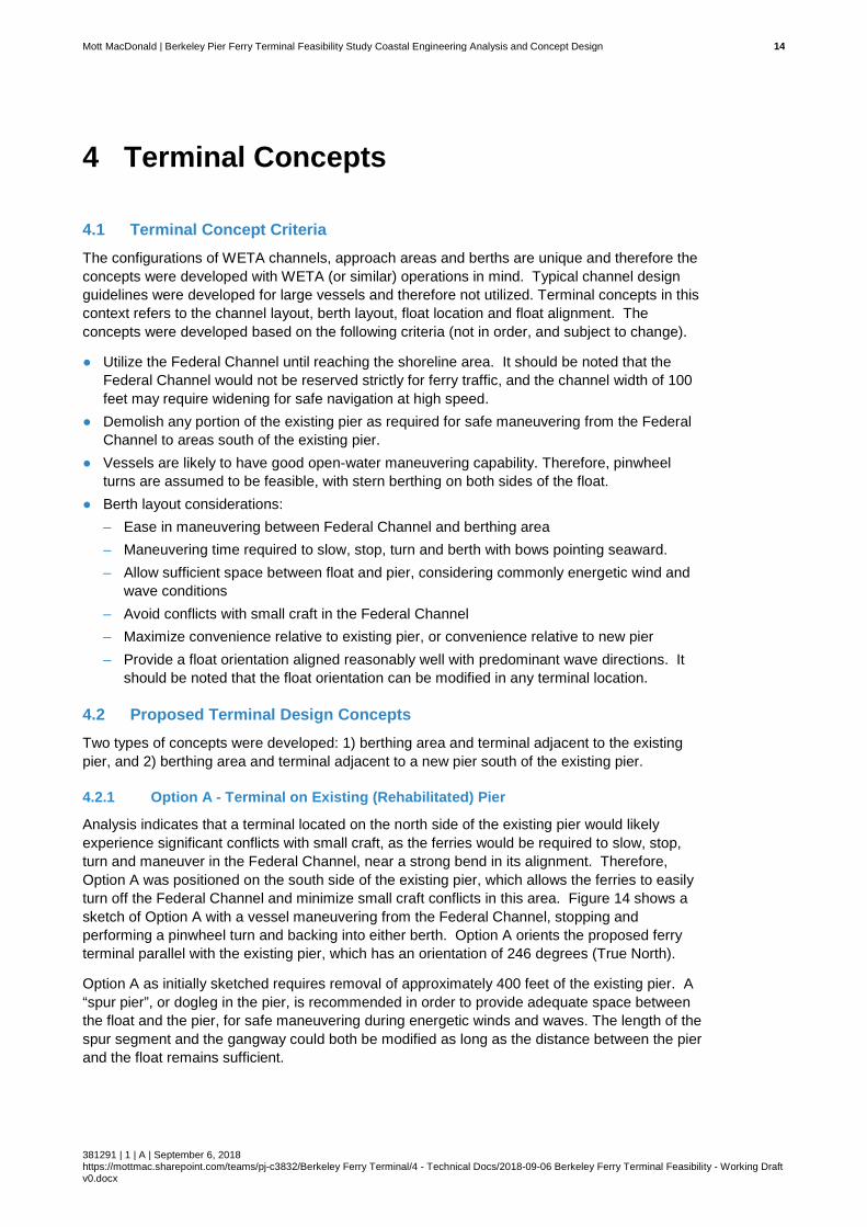
Mott MacDonald | Berkeley Pier Ferry Terminal Feasibility Study Coastal Engineering Analysis and Concept Design 14
381291 | 1 | A | September 6, 2018 https://mottmac.sharepoint.com/teams/pj-c3832/Berkeley Ferry Terminal/4 - Technical Docs/2018-09-06 Berkeley Ferry Terminal Feasibility - Working Draft v0.docx
4 Terminal Concepts
4.1 Terminal Concept Criteria The configurations of WETA channels, approach areas and berths are unique and therefore the concepts were developed with WETA (or similar) operations in mind. Typical channel design guidelines were developed for large vessels and therefore not utilized. Terminal concepts in this context refers to the channel layout, berth layout, float location and float alignment. The concepts were developed based on the following criteria (not in order, and subject to change).
● Utilize the Federal Channel until reaching the shoreline area. It should be noted that the Federal Channel would not be reserved strictly for ferry traffic, and the channel width of 100 feet may require widening for safe navigation at high speed.
● Demolish any portion of the existing pier as required for safe maneuvering from the Federal Channel to areas south of the existing pier.
● Vessels are likely to have good open-water maneuvering capability. Therefore, pinwheel turns are assumed to be feasible, with stern berthing on both sides of the float.
● Berth layout considerations: – Ease in maneuvering between Federal Channel and berthing area – Maneuvering time required to slow, stop, turn and berth with bows pointing seaward. – Allow sufficient space between float and pier, considering commonly energetic wind and
wave conditions – Avoid conflicts with small craft in the Federal Channel – Maximize convenience relative to existing pier, or convenience relative to new pier – Provide a float orientation aligned reasonably well with predominant wave directions. It
should be noted that the float orientation can be modified in any terminal location.
4.2 Proposed Terminal Design Concepts Two types of concepts were developed: 1) berthing area and terminal adjacent to the existing pier, and 2) berthing area and terminal adjacent to a new pier south of the existing pier.
4.2.1 Option A - Terminal on Existing (Rehabilitated) Pier
Analysis indicates that a terminal located on the north side of the existing pier would likely experience significant conflicts with small craft, as the ferries would be required to slow, stop, turn and maneuver in the Federal Channel, near a strong bend in its alignment. Therefore, Option A was positioned on the south side of the existing pier, which allows the ferries to easily turn off the Federal Channel and minimize small craft conflicts in this area. Figure 14 shows a sketch of Option A with a vessel maneuvering from the Federal Channel, stopping and performing a pinwheel turn and backing into either berth. Option A orients the proposed ferry terminal parallel with the existing pier, which has an orientation of 246 degrees (True North).
Option A as initially sketched requires removal of approximately 400 feet of the existing pier. A “spur pier”, or dogleg in the pier, is recommended in order to provide adequate space between the float and the pier, for safe maneuvering during energetic winds and waves. The length of the spur segment and the gangway could both be modified as long as the distance between the pier and the float remains sufficient.

Mott MacDonald | Berkeley Pier Ferry Terminal Feasibility Study Coastal Engineering Analysis and Concept Design 15
381291 | 1 | A | September 6, 2018 https://mottmac.sharepoint.com/teams/pj-c3832/Berkeley Ferry Terminal/4 - Technical Docs/2018-09-06 Berkeley Ferry Terminal Feasibility - Working Draft v0.docx
Figure 14: Option A ferry terminal concept, located on the south side of the existing pier
4.2.2 Option B - Terminal on New Southern Pier
Option B was also positioned south of the existing pier, also allowing the ferries to easily turn off the Federal Channel and minimize small craft conflicts in this area. Figure 15 shows a sketch of Option B with a vessel maneuvering from the Federal Channel, stopping and performing a pinwheel turn and backing into either berth. Option B orients the proposed ferry terminal parallel with a proposed new pier, which has an orientation of 257 degrees (True North).
Option B also requires removal of approximately 400 feet of the existing pier, and has a very similar “spur pier”, or dogleg in the pier, for safe maneuvering during energetic winds and waves. As with Option A, the length of the spur segment and the gangway could both be modified as long as the distance between the pier and the float remains sufficient.

Mott MacDonald | Berkeley Pier Ferry Terminal Feasibility Study Coastal Engineering Analysis and Concept Design 16
381291 | 1 | A | September 6, 2018 https://mottmac.sharepoint.com/teams/pj-c3832/Berkeley Ferry Terminal/4 - Technical Docs/2018-09-06 Berkeley Ferry Terminal Feasibility - Working Draft v0.docx
Figure 15: Option B ferry terminal concept, located on the north side of a new pier south of the existing pier
4.2.3 Float Alignments
Float alignments were evaluated to determine how closely they coincide with predicted wave directions, to minimize wave loads on the float and wave-induced motions of both the float and the moored vessels. Significant wave heights and peak wave directions were extracted from the Bay-wide wave transformation model at multiple points around the floats for both Option A and B. Figure 16 shows the locations where wave conditions were extracted (top) and a wave rose (bottom) which indicates the incident wave directions and significant wave heights at the point labeled #1076.
Modeling results show that Option A (at existing pier) has slightly better alignment than Option B in terms of wave direction, however both Options are relatively well aligned to the predominant wave directions. The float and vessel orientations were not evaluated relative to wind directions, which should be performed during later phases of design. Design waves and wave protection at the terminal has not been evaluated during this phase of the analysis. The terminal is subject to a stronger wave environment than any other ferry terminal in the Bay Area, and sufficient consideration must be given to its impacts on operations and maintenance.

Mott MacDonald | Berkeley Pier Ferry Terminal Feasibility Study Coastal Engineering Analysis and Concept Design 17
381291 | 1 | A | September 6, 2018 https://mottmac.sharepoint.com/teams/pj-c3832/Berkeley Ferry Terminal/4 - Technical Docs/2018-09-06 Berkeley Ferry Terminal Feasibility - Working Draft v0.docx
Figure 16: Wave extraction points near Berkeley Pier Ferry Terminal (top) and wave rose-histogram plot associated with point 1076 (bottom).

Mott MacDonald | Berkeley Pier Ferry Terminal Feasibility Study Coastal Engineering Analysis and Concept Design 18
381291 | 1 | A | September 6, 2018 https://mottmac.sharepoint.com/teams/pj-c3832/Berkeley Ferry Terminal/4 - Technical Docs/2018-09-06 Berkeley Ferry Terminal Feasibility - Working Draft v0.docx
5 Dredging Volumes
5.1 General Since future channel and berth depths are still under evaluation in coordination with the City of Berkeley and WETA, volumes for a range of different channel dimensions (depths and widths) were generated. Two different types of dredging volumes are provided
5.2 Dredging Volume Calculations Dredging volumes for different channel depths were computed using elevation model surfaces. At present, the channel width is assumed to remain at 100 feet and sit within the Federal Channel. 3H:1V side slopes were assumed for both the channel and berth areas. Figure 17 shows the dredging layouts and volumes for Options A and B, for various dredging depths between 8 and 12 feet (MLLW). Results show negligible differences in dredging volumes between the two Options. No construction tolerance or advanced maintenance was included in the calculations.
Although sedimentation is expected to be minimal, some level of over-dredging would be recommended due to an expected high cost per cubic yard for maintenance dredging. The Federal Channel requires deepening as noted, however and the Federal Channel may also require widening for safe navigation at high speeds since small craft also use the channel.
Figure 17: Dredging volumes for Option A and B, for various dredging depths

Draft Document – For Discussion Only – Final Version May Differ From Draft
GHD | Small Scale Ferry Terminal Feasibility Study | 11125268
Appendix C

GHD 655 Montgomery Street Suite 1010 San Francisco California 94111 USA T 415 283 4970 F 415 283 4980 W www.ghd.com
City of Berkeley – Municipal Pier Structural Assessment Berkeley Ferry Terminal Feasibility Study DRAFT Preliminary Basis of Design
A. INTRODUCTION This document describes the preliminary design criteria for the conceptual Berkeley Ferry Terminal to be located at Municipal Pier in Berkeley, CA. This document is intended to provide and document the preliminary design assumptions, operational criteria, safety and other requirements for the project. B. DESIGN CODES, REFERENCES AND STANDARDS The design requirements of the following design codes and standards will be incorporated into conceptual design of the Berkeley Ferry Terminal study:
1. American Bureau of Shipping (ABS), Rules for Building and Classifying Steel Barges, 2016. 2. American Concrete Institute, “Building Code Requirements for Structural Concrete,” ACI 318-14 and
Commentary (ACI 318R-14.) 3. American Institute of Steel Construction (AISC), “2005 LRFD Specification for Structural Steel
Buildings.” 4. American Institute of Steel Construction (AISC) Steel Construction Manual, 14th Edition, 2011 5. American Society of Civil Engineers, “Minimum Design Loads for Buildings and Other Structures,”
ASCE/SEI 7-10, 2010. 6. American Society of Civil Engineers, “Seismic Design of Piers and Wharves,” ASCE/COPRI 61-14. 7. American Society for Testing and Materials (ASTM), latest standards. 8. American Welding Society (AWS) – D1.1, latest version. 9. American Welding Society (AWS) D1.5, Bridge Welding Code, 2009. 10. California Building Standards Commission, “2016 California Building Code (CBC),” California Code
of Regulations, Title 24, Parts 1 and 2, 2016. 11. International Code Council, “2015 International Building Code (IBC),” 2015. 12. PIANC, “Guidelines to Design of Fender Systems,” 2002. 13. United States Access Board, Passenger Vessels, Chapter V4 14. US Department of Justice 2010 ADA standards for accessible design Title II (28 CFR part 35) and
Title III (28 CFR part 36). The project elements shall follow the codes and standards below for design:
1. MOTEMS, Chapter 31F 2013 CBC for ferry terminal vessel fender and mooring design. 2. ASCE 61-14 for seismic design of any pile-supported structures. 3. ABS standard for design and fabrication of steel float.
C. FUNCTIONAL AND OPERATIONAL CRITERIA
The ferry terminal will be designed to Essential Facility standards per 2016 California Building Code (Title 24.) General: The terminal will be used by WETA vessels for passenger loading and unloading. Two vessels shall be accommodated at the ferry float. Routine maintenance and overnight berthing of ferry vessels is not anticipated to be required.

Berkeley Municipal Pier Ferry Terminal Feasibility Study – DRAFT Preliminary Basis of Design July 2018 Page 2 of 6
1. Steel Float Size: 135’ length by 42’-0” width and approximately 10’ depth 2. Design Life: 50 years 3. Design Float Freeboard: 3 feet (+/- 1 inch)
Vessels: 1. Float shall accommodate ferry vessels loading / unloading and temporary mooring port and
starboard.
Float Superstructure: 1. Float shall have an elevated superstructure consisting of fixed and adjustable ramps, landings, gates
and guardrailing/handrails. 2. Float superstructure shall meet applicable state and federal regulations and comply with ADA
requirements. Range of motion (TOM) for adjustable ramps: • Forward adjustable ramp – TBD • Aft adjustable ramp – TBD
3. Adjustable ramps shall be capable of completing a full up and down range of motion of 60 seconds.
Ramps and Gangways: 1. Movable gangways shall be hinged to allow pivoting at the top with bottom free to move on platform. 2. Walkways and gangways shall be designed to accommodate passenger foot traffic, bicycles and
small equipment carts. 3. Gangways and walkways shall be uncovered. 4. Brow ramps shall be adjustable using electric or hydraulic motors and controls. 5. Light transmitting materials such as grating shall be considered for walking surfaces on platforms
and gangways.
Vessel Mooring Accessories: 1. Mooring accessories shall accommodate all float and ferry vessel dimensional and performance
requirements. 2. Mooring attachment arrangement shall not impact passenger access areas. 3. Arrangements shall protect ferry vessels from reasonably expected emergency situations
Utilities:
1. Electrical: two power receptacles shall be located on the float. 2. Lighting: gangway and float navigational lighting shall be provide that meets applicable state, US
Coast Guard, safety and ADA requirements. 3. Emergency Power: An emergency generator is not required. Emergency power for egress lighting
and operational needs to allow operation during loss of permanent power (clipper card, access control, security, ramp adjustment, etc.) shall be provided via batteries or a combination of batteries and solar power.
4. Water: potable water system on float. 5. Electronic Card Reader System: Clipper card reader system shall be provided and installed. System
shall include communications and power infrastructure. 6. Signage: “Next Bus” electronic signage for vessel tracking system shall be installed on gate. 7. Fire Suppression: Per the California Building Code and California Fire Code, the terminal float is
classified as an Assembly Group A-3. Consultation with the local authorities having jurisdiction (AHJ) will be required to determine fire protection requirements. A standpipe system may be required on the float, and possibly the fixed pier. Fire sprinklers may be required depending on the final configuration of an enclosed passenger shelter on the pier.
8. Sewage / Bilge: sanitary sewer connection or provisions for sewage / bilge pump out is not required.
Float Ballast System:

Berkeley Municipal Pier Ferry Terminal Feasibility Study – DRAFT Preliminary Basis of Design July 2018 Page 3 of 6
1. Float shall utilize a freshwater ballast system. The potable water system will be used to add water to the ballast tanks for adjusting trim and freeboard of the float.
2. The ballast system will use hoses to fill tanks through ports in each ballast hatch cover.
D. DESIGN LOADS AND LOADING COMBINATIONS Design loading combinations for the conceptual Berkeley Ferry Terminal are presented below. Design load combinations are summarized at the end of this section. The terminal float and access gangway will be designed for governing design load combinations per the requirements of the 2016 California Building Code. A summary of the recommended Design Criteria for the conceptual Berkeley Ferry Terminal Project follows:
1. Gravity Loading pcf = pounds per cubic foot psf = pounds per square foot plf = pounds per linear foot kips – 1 kip = 1,000 pounds
Dead Loads – self weight of all structures and fixed equipment, including permanent elements such as fenders, pile collars, mooring hardware, ramps and platforms, gangways and supports, utilities, permanent ballast and hydrostatic pressure. Unit Weights: Reinforced Concrete ....................................................................... 150 pcf Steel ................................................................................................ 490 pcf Aluminum ......................................................................................... 165 pcf Fiber Reinforced Polymer ................................................................ 115 pcf Seawater ........................................................................................... 64 pcf Miscellaneous Utilities ........................................................................ 20 plf Marine Growth on Submerged Surfaces ............................................. 5 psf
2. Live Loads – transient loading.
On float access ramps and gangways ............................................ 100 psf On float decks (uniform) .................................................................... 40 psf On float decks (concentrated) .................................................. 650 pounds
3. Gangway and Gangway Platform
Uniform Live Load .......................................................................... 100 psf Concentrated Live Load ................................................................. 500 psf Maximum Gangway Live Load Deflection ......................................... L/180 Handrail Uniform Live Load ....................... 50 plf applied at the top in any direction Concentrated Live Load ........... 250 lbs applied at the top in any direction
4. Buoyancy Loads
Buoyancy forces shall consist of uplift forces applied at the rate of 64 psf of plan area for every foot of submergence below water level.
5. Mooring Loads
Mooring bitts and attachments: 50 kips horizontal combined with 25 kips vertical applied 8 inches above float deck

Berkeley Municipal Pier Ferry Terminal Feasibility Study – DRAFT Preliminary Basis of Design July 2018 Page 4 of 6
6. Float Tow Attachments
Attachments for float tow shall be designed for a minimum of 55 kips breaking strength applied in any direction.
7. Vessel Berthing Loads
Berthing Velocity: 1.5 feet per second Incidence Angle: 10 degrees Mass: Added mass of water Impact: Applied at centerline of single fender
8. Float Stability Analysis
Stability analysis will be performed for the float structure consisting of hydrostatic properties, intact stability, damage stability and ballast assessment.
9. Seismic Loading
Seismic Design Category: D Site Class: E SS: 1.733 g S1: 0.687 g SDS: 1.040 g SD1: 1.100 g
10. Load Combinations per 2016 CBC:
Loading
D
D+L D+L+W D+L+EQ D-W D+IM
D, Dead 1.4 1.2 1.2 1.2 0.9 1.2 L, Live 1.6 1.0 1.0 E, Environmental W, Wind 1.6 1.6 EQ, Earthquake 1.0 IM, Accidental Impact 1.3
11. Environmental Loading:
Loading
Value
Wind (ASCE 7 3-sec gust, mph) 110 Exposure Category (ASCE 7) D Current (knots) 1.0 Significant Wave Height (HS, feet) 4.9 Significant Wave Peak Period (seconds) 4.9

Berkeley Municipal Pier Ferry Terminal Feasibility Study – DRAFT Preliminary Basis of Design July 2018 Page 5 of 6
E. MATERIAL PROPERTIES The following structural material and properties are anticipated to be use for the project:
Concrete All concrete shall be reinforced and utilize a mixture design suitable for the marine environment to meet the facility service life requirement. Structural Steel Plates and Bars ASTM A 131 or ASTM A 36 Wide Flange Shapes ASTM A 992 Pipe ASTM A 53, Grade B Tubes: Round or Rectangular HSS ASTM A 500, Grade B Angles and Channels ASTM A 36 All Other Plates ASTM A 992 Bolts ASTM A 325 Welding Electrodes ASTM E 70xx Nuts ASTM A 194 / ASTM A 563, Grade A Washers ASTM F 436 / F 844 Stainless Steel All shapes and plate ASTM A 276 Type 316
Aluminum Aluminum used for access gangway and walkway fabrication and other components shall be 6061-T6, 6063-T6, or per manufacturer’s specification. Bolts for use with structural aluminum shall be Type 316 stainless steel or per manufacturer’s specification and approved by Engineer. Corrosion Protection Passive cathodic protection system shall be used on steel float and piles consisting of zinc anodes.
F. GEOTECHNICAL CRITERIA Geotechnical criteria and parameters for preliminary and final design of the ferry terminal float guide piles and other piles will be based on site investigation and engineering studies conducted. G. ACCESSIBILITY REQUIREMENTS Gangway and ramps shall meet requirements of ADA-ADAAG and Draft Passenger Vessel Accessibility Guidelines. Minor deviations from accessibility standards are possible at the most extreme tides which may occur approximately several hours per year. H. DESIGN DATA
Parameter
Design Vessel
Vessel WETA 250-325
Passenger Ferry Length Overall, L 120 feet Beam 31’-0”
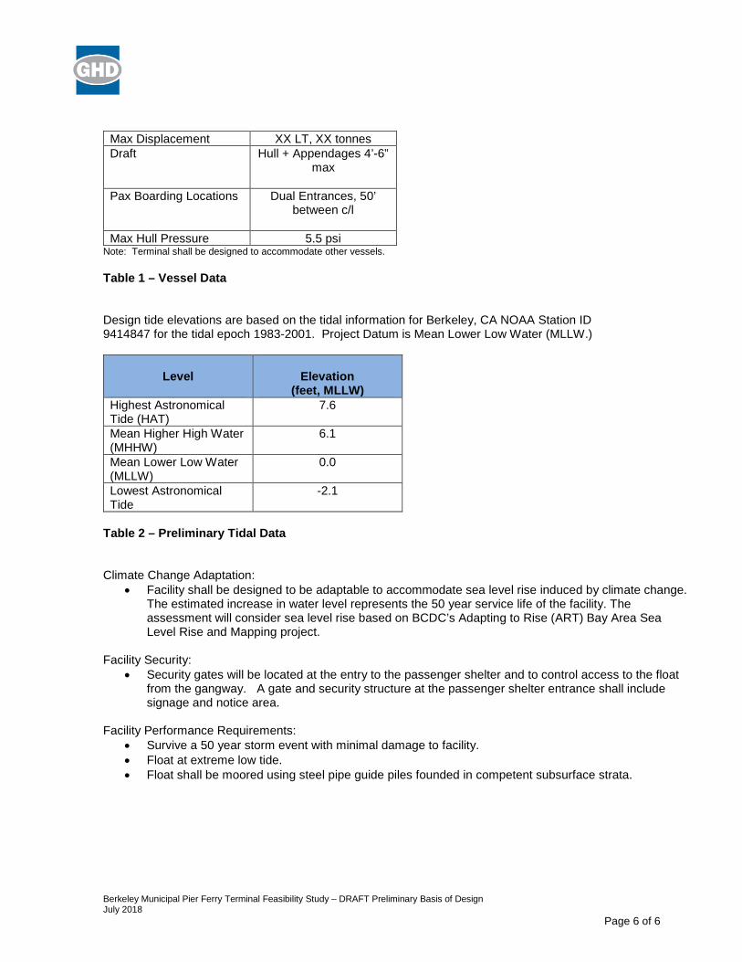
Berkeley Municipal Pier Ferry Terminal Feasibility Study – DRAFT Preliminary Basis of Design July 2018 Page 6 of 6
Max Displacement XX LT, XX tonnes Draft Hull + Appendages 4’-6”
max
Pax Boarding Locations Dual Entrances, 50’ between c/l
Max Hull Pressure 5.5 psi
Note: Terminal shall be designed to accommodate other vessels.
Table 1 – Vessel Data Design tide elevations are based on the tidal information for Berkeley, CA NOAA Station ID 9414847 for the tidal epoch 1983-2001. Project Datum is Mean Lower Low Water (MLLW.)
Level
Elevation
(feet, MLLW) Highest Astronomical Tide (HAT)
7.6
Mean Higher High Water (MHHW)
6.1
Mean Lower Low Water (MLLW)
0.0
Lowest Astronomical Tide
-2.1
Table 2 – Preliminary Tidal Data Climate Change Adaptation:
• Facility shall be designed to be adaptable to accommodate sea level rise induced by climate change. The estimated increase in water level represents the 50 year service life of the facility. The assessment will consider sea level rise based on BCDC’s Adapting to Rise (ART) Bay Area Sea Level Rise and Mapping project.
Facility Security:
• Security gates will be located at the entry to the passenger shelter and to control access to the float from the gangway. A gate and security structure at the passenger shelter entrance shall include signage and notice area.
Facility Performance Requirements:
• Survive a 50 year storm event with minimal damage to facility. • Float at extreme low tide. • Float shall be moored using steel pipe guide piles founded in competent subsurface strata.

Draft Document – For Discussion Only – Final Version May Differ From Draft
GHD | Small Scale Ferry Terminal Feasibility Study | 11125268
Appendix D

CONCEPT LEVEL CONSTRUCTION COST ESTIMATECity of Berkeley - Municipal Pier Ferry Terminal Feasibility Study
Ferry Terminal and Dual Purpose PierClient: City of BerkeleyProject: Berkeley Municipal Pier Date: 11-Sep-18
Unit Cost TotalDescription - Dock Extension No Unit $/unit CostGeneral Description of Work
1 Mobilization / Demobilization 1 LS $2,327,050 $2,327,050Dual Purpose PierDemolition
2 Demolish Existing Pier Structure (partial demolition) 8,000 SF $22.00 $176,000
Pier Piles3 24"octagonal precast concrete piles (95 LF, furnish and install) 36 EA $18,800.00 $676,800
Precast Deck Panels4 Hollowcore Concrete Deck Panels (12" thickness, 32' span) 8,800 SF $52.00 $457,600
Bent Caps5 CIP Concrete Bent Caps 320 CY $1,375.00 $440,000
6 Pier Approach Soil Improvement (Allowance)Deep Soil Mixing (DSM) 4,500 CY $250.00 $1,125,000
7 Pier Access Ramp 1,080 SF $360.00 $388,800Pier Access Ramp (1:12 slope from landside, 60'x18')
8 Windscreen and Sun Cover StructureFerry Passenger Wind Screen and Cover Structure 3,870 SF $155.00 $599,850
9 UtilitiesWater, electrical, communications 1 LS $900,000 $900,000
Above Deck 10 Guard Railing (galv steel) 1,400 LF $110.00 $154,00011 Light Poles and Fixtures 40 EA $7,200.00 $288,000
Ferry TerminalFerry Float
12Steel Float (135'x42'x8' barge fabrication, piles guides, vertical fenders, and appurtenances 5,670 SF $825.00 $4,677,750
13 48" Guide Piles (1" wall, 120LF, marine coating, anodes, pile caps) 4 EA $153,000 $612,000
1436" Dolphin Piles (1" wall, 110LF, marine coating, anodes, pile caps, 60" donut fenders) 2 EA $355,000 $710,000
15 Float Access Gangway (110' long x10' wide) 1 LS $235,000 $235,000
16 Elevated Walkways on Float Deck 1 LS $650,000 $650,000
17 Adjustable Brow Ramps on Float 6 EA $150,000 $900,000
18 Security Gate at Pier Access Control Point 1 LS $325,000 $325,000
19 Mechanical Utilities 1 LS $250,000 $250,000
20 Electrical System 1 LS $300,000 $300,000
21 Dredging (-8' MLLW elevation with 10% over dredging assumed) 28,800 CY $37 $1,065,600
Landside Improvements22 Grading and Paving (road and parking area) 1 LS $1,200,000.00 $1,200,000
23 Concrete Flatwork 1 LS $800,000.00 $800,000
24 Landscaping and Bicycle Parking/Lockers 1 LS $900,000.00 $900,000
25 Storm Drainage 1 LS $340,000.00 $340,000
26 Site Lighting 1 LS $300,000.00 $300,000
27 Water Service 1 LS $25,000.00 $25,000
28 Signage/Wayfinding 1 LS $120,000.00 $120,000
Subtotal $20,943,450
Additional Estimating Contingency 25% $5,235,862.50TOTAL ESTIMATED CONSTRUCTION COSTS $26,179,313
Notes: 1. Cost estimate presented above is considered rough order of magnitude (ROM).2. Construction quantities shown are approximate.3. Soil improvements at the pier approach are assumed (liquefaction mitigation.)3. Landside improvements will require further study. An estimation of improvements has been included.4. Dredging cost assumes non-contaminated sediment suitable for disposal at SF-DODS (deep ocean disposal)
Quantity
Berkeley Municipal Pier - Replacement Alternative P10 - Demo portion of existing pier for new pier and ferry navigation - New pier with precast deck panels and precast concrete piles, 1st segment:130 LF x 18' wide, ferry access: 85'x18',3rd segment: 300'x16' - Ferry Terminal (135'x42' steel float, 4 guide pile and 2 dolphin piles,