Constructive Computer Architecture Tutorial 7: SMIPS Labs and Epochs Andy Wright 6.S195 TA

X-650-73-286
SMALL INTERACTIVE IMAGEPROCESSING SYSTEM (SMIPS)
SYSTEM DESCRIPTION
JOHANNES G. MOIK
(NASA-TM-X-70473) SMALL INTERACTIVE IMAGE N73-32085PROCESSING SYSTEM (SMIPS) SYSTEMDESCRIPTION (NASA) 48 p HC
CSCL 09B UnclasG3/08 18196
SEPTEMBER 1973
GODDARD SPACE FLIGHT CENTERGREENBELT, MARYLAND
Reproduced by
NATIONAL TECHNICALINFORMATION SERVICE
US Dep:,:!ninnt of CommorcoSprrulild, VA. 22151
https://ntrs.nasa.gov/search.jsp?R=19730023353 2018-06-09T18:27:46+00:00Z

X-650-73-286
SMALL INTERACTIVE IMAGE PROCESSING SYSTEM (SMIPS)
SYSTEM DESCRIPTION
Johannes G. Moik*Code 650.1, Goddard Space Flight Center
Greenbelt, Maryland 20771
September, 1973
*National Academy of SciencesResearch Associate
NASA-Goddard Space Flight CenterOn Leave of absence from Institut fuer Angewandte
Mathematik und InformationsverarbeitungTechnische Hochschule Graz, Austria
/
SMALL INTERACTIVE IMAGE PROCESSING SYSTEM (SMIPS)
SYSTEM DESCRIPTION
Johannes G. MoikCode 650.1, Goddard Space Flight Center
Greenbelt, Maryland 20771
ABSTRACT
The SMIP system description gives detail of the executiveportion of the Small Interactive Image Processing System(SMIPS). The system operates under control of the IBM-OS/MVT operating system and uses an IBM-2250 model 1 displayunit as interactive graphic device. The input language in theform of character strings or attentions from keys and lightpen is interpreted and causes processing of built-in imageprocessing functions as well as execution of a variable num-ber of application programs kept on a private disk file. Ma-jor design goals were minimal impact on overall computersystem performance, convenient communication between userand system, modularity and fast input/output routines.
This document contains a description of design considerationsand summarizes characteristics, structure and logic flow ofSMIPS. It discusses also data management and graphic pro-gramming techniques used for the interactive manipulationand display of digital pictures.
Preceding page blank
iii

CONTENTS
Page
ABSTRACT ......................... iii
1. INTRODUCTION ........................ 1
2. DESIGN CONSIDERATIONS ................... 2
3. FUNCTIONAL CHARACTERISTICS . ............... 4
4. STRUCTURE OF THE SMIP SYSTEM . ....... . . . . . . . 6
4.1 STATE DIAGRAM OF SMIPS . ............ . . 6
4.2 DIALOGUE ENVIRONMENT . ............... 8
4.2. 1 Supervisor Module VICINT . ........... . 8
4.2.2 Dialogue Processor INTRPRET . ....... . ... .10
4.3 INPUT ENVIRONMENT ................... 14
4.4 TASK PROCESSING ENVIRONMENT . ........... 23
4.4.1 Task Characteristics . . . . ............ 24
4.4.2 Communication between SMIPS and ApplicationPrograms ................... . 25
4.4.3 Communication between Application Programs . . .. 25
4.4.4 Adding or Replacing a Program in a Library . . . .. 27
5. DATA ORGANIZATION IN SMIPS . . . . . . . . . . . . . . . . 28
5.1 DATA STRUCTURES ...................... 28
5.2 OPERATIONS ON THE DATA STRUCTURES . ..... . . 30
5.3 INTERFACE SMIPS TO OS/360 . ........ . . . . . 31
5.4 DATA MANAGEMENT IN SMIPS ,...... . . . ..... . . 32
v Preceding page blank
CONTENTS (Continued)
Page
6. GRAPHIC PROGRAMMING TECHNIQUES . ....... . . . . 34
6.1 DEFINITION OF AN IMAGE ........ ....... 34
6.2 IMAGE STRUCTURES ................. 35
6.3 DESCRIPTION OF THE IBM 2250 DISPLAY UNIT . . . . . 37
6.4 PROGRAMMING THE 2250 DISPLAY UNIT . . . . . . . 39
6.5 COMMUNICATION HANDLING . . . . . . . . . . . . . . 40
6.6 COMMUNICATION WITH THE 2250 DISPLAY UNIT . . . . 41
7. LIGHT PEN TRACKING ..... . . . . . . .... 41
REFERENCES .................... .. .... 42
ILLUSTRATIONS
Figure Page
1 State Diagram of SMIPS... ..... ... . .... 7
2 State Diagram of Dialogue Environment . ........ . 9
3 INTRPOC Flowchart (1 of 3) ................ 11
4 JCL for VICINT ............. ....... 14
5 INTRPRET Flowchart (I of 3) . .............. 15
6 READ Command Processor Flowchart . . . ..... . . . . . 18
7 TAPOS Flowchart 19
8 DISPLAY Command Processor Flowchart (1 of 2) ... . . . . 20
vi
ILLUSTRATIONS (Continued)
Figure Page
9 JCL for INTRPRET ................... . 22
10 TASKPROC JCL ................... .. 24
11 Parameter Table ................... .. 26
12 Mail Block Format .................... 26
13 27
14 27
15 Correspondence Picture Name-Picture Values . . . .. . . . 32
16 Structured Display File . .......... . . . . . . . 35
17 Scaled Display File .................... 36
18 Display File Tree. ................... . 37
19 Buffer Control Table ....... . . .... ..... 39
20 Graphic ControlBlock. ....... ........... 41
vii
SMALL INTERACTIVE IMAGE PROCESSING SYSTEM
SYSTEM DESCRIPTION
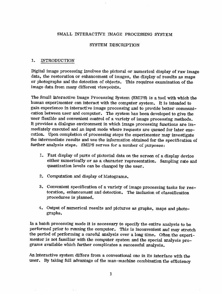
1. INTRODUCTION
Digital image processing involves the pictoral or numerical display of raw imagedata, the restoration or enhancement of images, the display of results as mapsor photographs and the detection of objects. This requires examination of theimage data from many different viewpoints.
The Small Interactive Image Processing System (SMIPS) is a tool with which thehuman experimenter can interact with the computer system. It is intended togain experience in interactive image processing and to provide better communi-cation between user and computer. The system has been developed to give theuser flexible and convenient control of a variety of image processing methods.It provides a dialogue environment in which image processing functions are im-mediately executed and an input mode where requests are queued for later exe-cution. Upon completion of processing steps the experimenter may investigatethe intermediate results and use the information obtained for the specification offurther analysis steps. SMIPS serves for a number of purposes:
1. Fast display of parts of pictorial data on the screen of a display deviceeither numerically or as a character representation. Sampling rate andquantization levels can be changed by the user.
2. Computation and display of histograms.
3. Convenient specification of a variety of image processing tasks for res-toration, enhancement and detection. The inclusion of classificationprocedures is planned.
4. Output of numerical results and pictures as graphs, maps and photo-graphs.
In a batch processing mode it is necessary to specify the entire analysis to beperformed prior to running the computer. This is inconvenient and may stretchthe period of performing a careful analysis over a long time. Often the experi-menter is not familiar with the computer system and the special analysis pro-grams available which further complicates a successful analysis.
An interactive system differs from a conventional one in its interface with theuser. By taking full advantage of the man-machine combination the efficiency
1
of a picture analysis can be increased considerably. By means of a display devicewhich allows also to control the computer, the user specifies his input and thesystem displays the results on the screen. Thus the short time between specifi-cation of a problem and' the return of intermediate results makes possible a moreintelligent choice and sequencing of the analysis steps that are applied to the pic-tures.
This document describes the structure of the SMIP system, the system modulesand its various routines and the conventions for writing application programs.It should enable a programmer to maintain, expand or modify the system. Ausers manual for SMIPS is available [11.
2. DESIGN CONSIDERATIONS
The design of an interactive image processing system is greatly influenced bydata management problems because the large matrices representing digital pic-tures cannot be contained entirely in core storage. An image processing systemneeds, therefore, external mass storage, usually magnetic disk storage.
The raster-scan operation of image digitizers and scanning instruments on space-crafts imposes a sequential-row access structure on the sampled image data.Therefore, the fundamental unit of the data structure is one row of the imagematrix and a row is stored as one physical record on a sequential-access storagemedium, magnetic tape. Magnetic tapes are used as permanent storage forlarge quantities of image data. It is natural to use the same data structure in animage processing system and consequently to store images as sequential rowaccess files on magnetic disk during the execution of image processing programs.
Most of the image processing operations are performed on lines or columns ofa picture and random access is not required. Each access retrieves one row ofthe image matrix which is processed and placed into another sequential file.This structure, however, makes operations on columns difficult, e.g. the columnoperations in a fast Fourier transform.
Storage of pictures on disk and accessing individual rows results in an I/O-boundprogram. The elapsed time to transfer a picture line to core storage is usuallymuch longer than the time required for numerical computation on the data. Thesituation can be improved by blocking, i.e. grouping of several logical recordsinto a physical. Thus, several logical records are transferred with one accessinto core storage. This requires, however, a larger area in core storage. In
2
addition the time lost in waiting for I/O operations can be reduced by a goodI/O buffering system which attempts to supply new records as fast as old onesare processed. The extent to which these I/O operations exceed the actual timerequired for numerical computation determines how much an image processingprogram becomes I/O-bound. Generally, the increase of main storage areas forblocking and buffering will reduce the I/O-boundedness of a program.
The optimal design decision is dependent on the computer system used to operatethe image processing system. In a multiprogramming operating system an I/O-bound program is no liability. In a multiprogramming system several differentprograms reside in main memory simultaneously with only one program exe-cuting at any given time. When the program in execution requests an I/O opera-tion, its execution is suspended and another program begins execution. Concur-rently a channel (peripheral processor) is assigned to perform the I/O operationrequested by the suspended program. Thus, an I/O-bound program does notwaste any of the total computing time of the central processor. As long as theimage processing system does not overburden the main memory of the computer,there is room for other programs to share the memory. Thus, the chief impactof the multiprogramming environment on the design of an image processing sys-tem is to minimize the utilization of central processor and main memory.
Minimal main memory utilization is even more important in the design of aninteractive image processing system. In such a system short computations arefollowed by relatively long periods of waiting for input from the user. Theseperiods of thinking and decision making may last several minutes. An adequateenvironment for an interactive image processing system is a timesharing systemwith paging, where parts of the program are transferred to external storageduring wait periods in order to free main storage for other users. In such asystem the design goal is to keep the page traffic between main storage and back-ing storage to a minimum.
In a multiprogramming system with no dynamic allocation and deallocation ofresources (main storage, tape units, disk storage) like IBM-OS/360, all re-sources needed by the interactive image processing system remain allocatedfrom start to end of operation and are not available to other users.
The SMIP system operates under OS-MVT, its major design goals are, there-fore, minimal utilization of main storage and tape units at the expense of diskspace on scratch disk units and some overhead for unloading tapes if severaltapes are required in a sequence.
If a multiprogramming system is not available the design goal for an image pro-cessing system is to make it as little I/O-bound as possible. These efforts in-clude overlapping I/O operations and computation by buffering, optimal blocking
3
and disk separation if separate disks on independent channels are available. Aninteractive image processing system can probably not be implemented in such anenvironment if many other people request the use of the computer system.
3. FUNCTIONAL CHARACTERISTICS
The SMIP system is designed for digital processing and recording of pictoral datain an interactive mode. Objectives of the system are convenient communicationwith the computer by users who are not expert programmers, fast response torequests for processing of pictures, complete error recovery as well as simpli-fication of future programming efforts for extension of the system.
The SMIP system is intended for operation on an IBM 360 computer equippedwith an IBM-2250 Model 1 display unit. The current implementation runs oneither the 360/75 or the 360/91 computers at SESD of GSFC under OS/MVT-Release 20.6. The system needs a core region of 200K bytes and uses one 9-track and one 7-track tape unit and space on five scratch disk units. The 2250display unit is used as display device, its alphameric keyboard, function keysand light pen provide for convenient communication between user and computer.
To allow the use of already existing image processing programs and to avoidconsiderable reprogramming effort, the SMIP system was made fully compatiblewith the VICAR system designed at the Jet Propulsion Laboratory. A SMIPSuser can execute any image processing program contained in the VICAR Libraryon the 360/75.
Operation of the SMIP system is similar to the use of a desk calculator. It isa repeated sequence of single requests followed by responses. The user requestsa computation by typing a command, pressing a function key or using the lightpen. The system responds with the display of a message or picture on the screenof the graphic terminal or by indicating the completion of the request with anaudible alarm signal. Thus, SMIPS is an interpretive system.
Three modes of operation can be distinguished. In the dialogue mode each com-mand issued by the user is interpreted and the appropriate processor is calledfor execution of the command. In the input mode each command is interpreted asa request for an image processing task, the corresponding program should existin the systems library. These requests are inserted into the task queue TFILE.Here lies the extendability of the system without increasing the core size, newimage processing programs are added to the library and can then be specified astasks in the input mode. The functions for these two modes are performed bythe system module VICINT which handles the communication between user and
4
computer and the input/output operations and by the system module INTRPROCwhich contains the command interpreter and the processors associated witheach command.
The image processing tasks queued in the task queue are processed in the taskprocessing mode. Each task involves the execution of a program which mustexist in the system program library. Execution is started by deleting INTRPROCfrom core. VICINT loads in its place a transient routine TASKPROC which readsthe task queue and initiates the first task. This task replaces TASKPROC incore. Upon completion, TASKPROC is reloaded and the next task in initiated.When the last task has been completed, control is returned to VICINT which re-loads INTRPRET and waits for further input from the user.
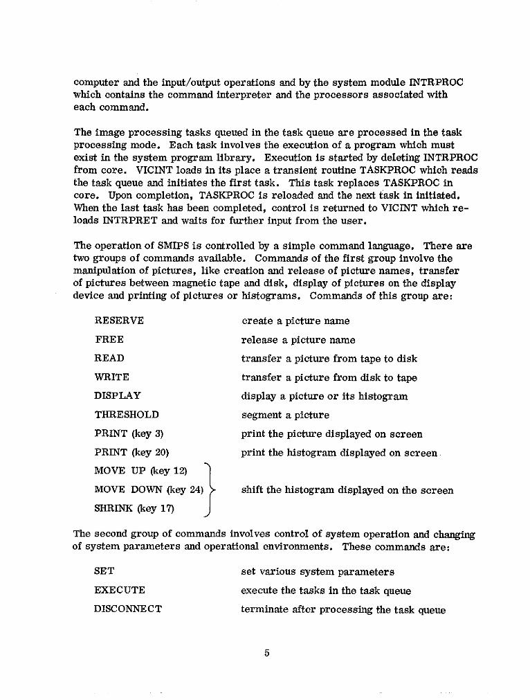
The operation of SMIPS is controlled by a simple command language. There aretwo groups of commands available. Commands of the first group involve themanipulation of pictures, like creation and release of picture names, transferof pictures between magnetic tape and disk, display of pictures on the displaydevice and printing of pictures or histograms. Commands of this group are:
RESERVE create a picture name
FREE release a picture name
READ transfer a picture from tape to disk
WRITE transfer a picture from disk to tape
DISPLAY display a picture or its histogram
THRESHOLD segment a picture
PRINT (key 3) print the picture displayed on screen
PRINT (key 20) print the histogram displayed on screen
MOVE UP (key 12)
MOVE DOWN (key 24) shift the histogram displayed on the screen
SHRINK (key 17)
The second group of commands involves control of system operation and changingof system parameters and operational environments. These commands are:
SET set various system parameters
EXECUTE execute the tasks in the task queue
DISCONNECT terminate after processing the task queue
5

EXIT terminate immediately
TASKS display tasks in task queue
TIME (key 4) display remaining time
NAMES (key 9) display currently used picture names
INPUT (key 10) enter input mode
PARAM (key 16) display system parameters
GUIDE (key 22) display users guide
EXIT (key 31) terminate immediately
Errors in the commands are detected, an explanatory message is displayed onthe screen and the system waits for specification of the correct command. Thiserror recovery feature makes the use of an interactive system very convenientfor there is little delay due to a mistake. A detailed description of the commandsis given in [1].
4. STRUCTURE OF THE SMIP SYSTEM
The SMIP system disposes of three operating environments, the dialogue environ-ment, the input environment and the task processing environment. In this chap-ter the three environments as well as the structure of the program modules in-volved in their operation will be described in some detail.
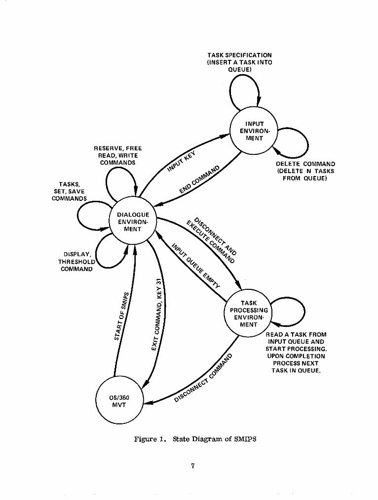
4.1 STATE DIAGRAM OF SMIPS
The structure of the SMIP system can be described using a finite state machinemodel. In the dialogue and input environment the system accepts input (controlinformation) from the user. These two environments provide for the interactionbetween user and the system. In the task processing environment no interactionis possible while the system processes previously specified tasks. The user hasto wait for completion of processing which is indicated by display of the cursorand a single stroke audible alarm to attract the users attention.
The transfer from one environment to another is accomplished with commandsor function keys. Fig. 1 represents the state diagram of the SMIP system. Itshows the commands and events which leave the system in the same environ-ment, as well as the conditions for transfer from one environment to another. Adetailed description of the commands is contained inthe SMIPS Users Manual [11.
6
TASK SPECIFICATION(INSERT A TASK INTO
QUEUE)
INPUTENVIRON-
MENT
RESERVE, FREEREAD, WRITECOMMANDS v DELETE COMMAND
(DELETE N TASKSFROM QUEUE)
SET, SAVE 6COMMANDS
DIALOGUE
ENVIRON- COMMENTME
DISPLAY,
THRESHOLD N XCOMMAND I UE
TASKNO P SPROCESSING
PROCESS NEXTENVIRON-
TASK IN QUEUE.
OS/360 91*MVT
Figure 1. State Diagram of SMIPS
7

4.2 DIALOGUE ENVIRONMENT
The basic set of image processing functions is available in the dialogue environ-ment. Each request is immediately executed. The commands available can beused to perform allocation and deallocation of disk space for pictures (RESERVE,FREE), transfer of pictures between disk and tape (READ, WRITE), display ofpictures, histograms and label information (DISPLAY) and change of various sys-tem parameters (SET). Utility functions are provided to inform the user on thecurrent state of the system, i.e. remaining processing time (KEY 4), tasks ininput queue (TASKS), current value of system parameters (KEY 16) and currentstatus of the catalogue of existing pictures in the system (KEY 9). Control func-tions permit display of a brief users guide (KEY 22), execution of the image pro-cessing programs in the task queue (EXECUTE), termination with previous pro-cessing of the programs in the task queue (DISCONNECT) and immediate termina-tion (EXIT or KEY 31).
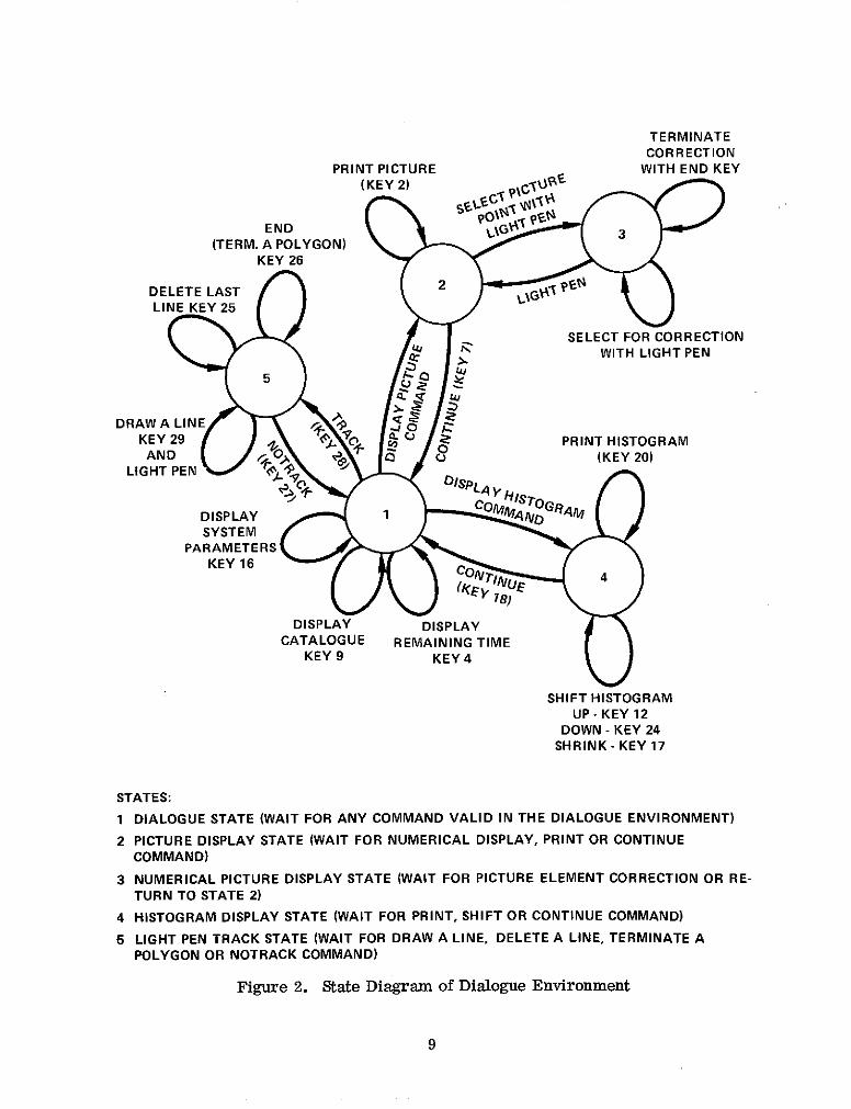
In the dialogue mode two SMIP system modules VICINT and INTRPRET are inmain memory. VICINT is loaded into main memory when the system is startedand is the only permanent core resident module of SMIPS. Its main functions areto enable the communication between user and computer, to provide the interfaceto the data management functions of OS/MVT and to load and delete the modulesINTRPRET and TASKPROC as well as the image processing programs into mainmemory. The state diagram for the dialogue environment is shown in Fig. 2.
4.2.1 Supervisor Module VICINT
The supervisor module VICINT is the core resident part of SMIPS. It containsthe interactive handler INTPROC, the Input/Output handler and some utility rou-tines. INTPROC allocates the IBM-2250 display device, assigns buffer storage toit, establishes the routines to handle attentions from light pen, function keys andend-of-block key and allocates a work area where display files are assembled forefficient transfer between main memory and the 2250-buffer. A brief guide to theusage of the SMIP system is displayed on the screen and INTPROC waits for acontinuation signal. Upon receiving this signal from key 0 the permanently dis-played figures (headline, frame) and the cursor for input from alphameric key-board are displayed and the module INTRPRET is loaded into main memory.
This module contains the scanner, interpreter and the routines to construct thedisplay files for the display of pictures, histograms and label information, theroutines for transfer of pictures between tape and disk, routines for light pentracking and for processing the task specification statements. After loading, thetransfer vector containing the addresses of the core resident routines referencedin INTRPRET is built and the system enters a wait state awaiting attentions fromthe user.
8
TERMINATECORRECTION
PRINT PICTURE WITH END KEY(KEY 2) "
END LIG 3(TERM. A POLYGON)
KEY 26
DELETE LAST 2LINE KEY 25
SELECT FOR CORRECTION4 WITH LIGHT PEN
DRAW A LINE 0 ZKEY 29 9Q PRINT HISTOGRAMAND 0 O (KEY 20)
LIGHT PEN .
DISPLAY 1 CO GRA
SYSTEMPARAMETERS
KEY 16 COTI
DISPLAY DISPLAYCATALOGUE REMAINING TIME
KEY 9 KEY 4
SHIFT HISTOGRAMUP - KEY 12
DOWN - KEY 24SHRINK- KEY 17
STATES:
1 DIALOGUE STATE (WAIT FOR ANY COMMAND VALID IN THE DIALOGUE ENVIRONMENT)
2 PICTURE DISPLAY STATE (WAIT FOR NUMERICAL DISPLAY, PRINT OR CONTINUECOMMAND)
3 NUMERICAL PICTURE DISPLAY STATE (WAIT FOR PICTURE ELEMENT CORRECTION OR RE-TURN TO STATE 2)
4 HISTOGRAM DISPLAY STATE (WAIT FOR PRINT, SHIFT OR CONTINUE COMMAND)
5 LIGHT PEN TRACK STATE (WAIT FOR DRAW A LINE, DELETE A LINE, TERMINATE APOLYGON OR NOTRACK COMMAND)
Figure 2. State Diagram of Dialogue Environment
9
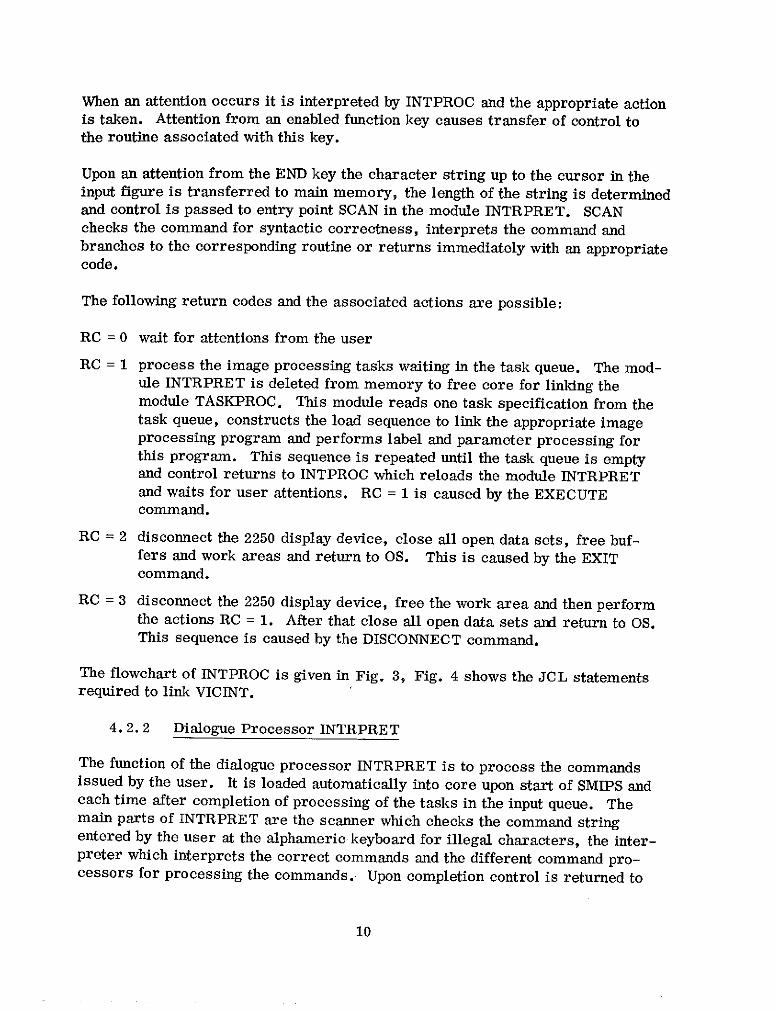
When an attention occurs it is interpreted by INTPROC and the appropriate actionis taken. Attention from an enabled function key causes transfer of control tothe routine associated with this key.
Upon an attention from the END key the character string up to the cursor in theinput figure is transferred to main memory, the length of the string is determinedand control is passed to entry point SCAN in the module INTRPRET. SCANchecks the command for syntactic correctness, interprets the command andbranches to the corresponding routine or returns immediately with an appropriatecode.
The following return codes and the associated actions are possible:
RC = 0 wait for attentions from the user
RC = 1 process the image processing tasks waiting in the task queue. The mod-ule INTRPRET is deleted from memory to free core for linking themodule TASKPROC. This module reads one task specification from thetask queue, constructs the load sequence to link the appropriate imageprocessing program and performs label and parameter processing forthis program. This sequence is repeated until the task queue is emptyand control returns to INTPROC which reloads the module INTRPRETand waits for user attentions. RC = 1 is caused by the EXECUTEcommand.
RC = 2 disconnect the 2250 display device, close all open data sets, free buf-fers and work areas and return to OS. This is caused by the EXITcommand.
RC = 3 disconnect the 2250 display device, free the work area and then performthe actions RC = 1. After that close all open data sets and return to OS.This sequence is caused by the DISCONNECT command.
The flowchart of INTPROC is given in Fig. 3, Fig. 4 shows the JCL statementsrequired to link VICINT.
4. 2. 2 Dialogue Processor INTRPRET
The function of the dialogue processor INTRPRET is to process the commandsissued by the user. It is loaded automatically into core upon start of SMIPS andeach time after completion of processing of the tasks in the input queue. Themain parts of INTRPRET are the scanner which checks the command stringentered by the user at the alphameric keyboard for illegal characters, the inter-preter which interprets the correct commands and the different command pro-cessors for processing the commands. Upon completion control is returned to
10
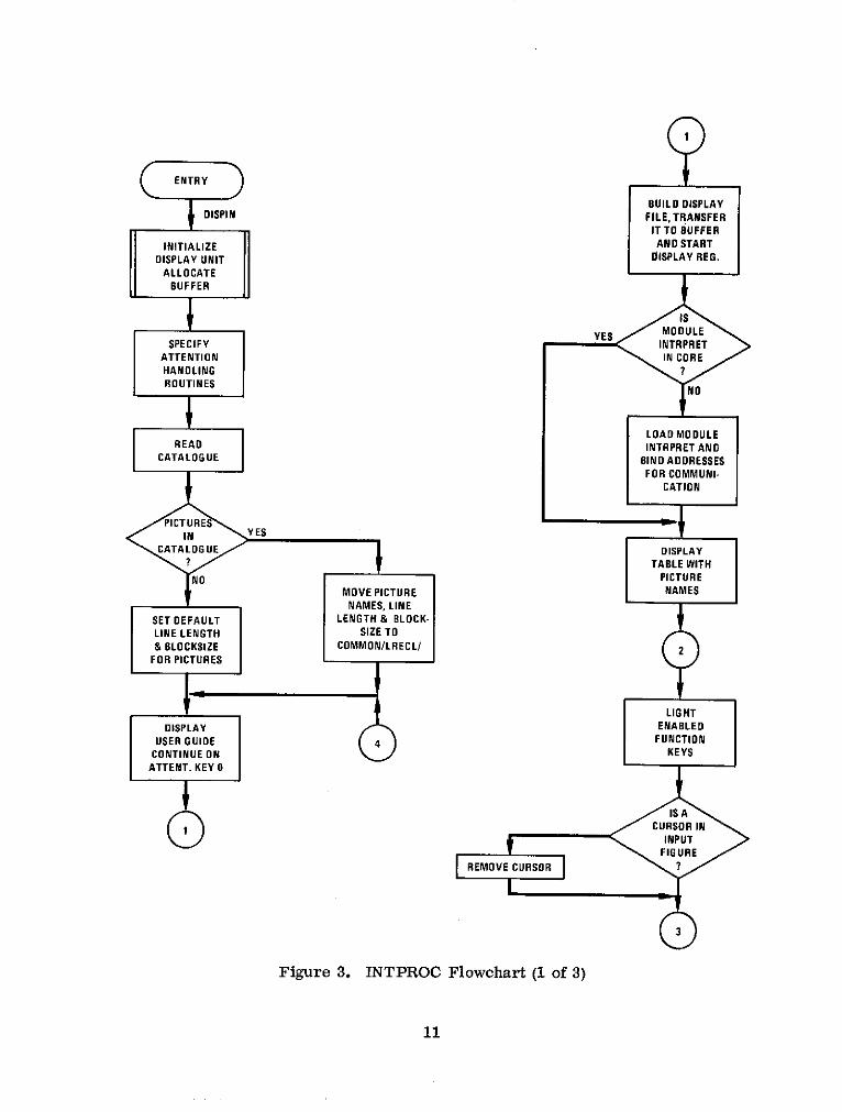
ENTRY
SBUILD DISPLAYDISPIN FILE, TRANSFER
IT TO BUFFER
INITIALIZE AND START
DISPLAY UNIT DISPLAY REG.
ALLOCATE
BUFFER
YES MODULESPECIFY INTRPRET
ATTENTION INCOREHANDLING ?ROUTINES
NO
LOAD MODULEREAD INTRPRET AND
CATALOGUE BIND ADDRESSESFOR COMMUNI-
CATION
PICTURESIN YES
CATALOGUE DISPLAY? O TABLE WITH
NO PICTUREMOVE PICTURE NAMES
SET DEFAULT LENGTH & BLOCK-LINE LENGTH SIZE TO
& BLOCKSIZE COMMON/LRECL/ 2FOR PICTURES
LIGHT
DISPLAY ENABLED
CONTINUE ON KEYSATTENT. KEY 0
IS A
1 1 CURSORININPUT
FIGUREREMOVE CURSOR ?
3
Figure 3. INTPROC Flowchart (1 of 3)
11

3
INSERT CURSOR KEY4 YES DISPLAYAT BEGIN INPUT T REMAININGME
FIGURE AND TIME
SOUND ALARM NO
DISPNAM
WAIT KEY 9 YES DISPLAYFOR INPUT PICTURE 2FROM USER NAMES
NO
ATTENTIONTYPE FUNCTION KEY INPUT
END KEY NO
TRANSFER DISPVALINPUT STRING
FROM 2250 BUFFER KEY16 YES DISPLAYTO MAIN MEMORY 7 SYSTEM 2
PARAMETERS
SCAN
BRANCH TOENTRY SCAN IN
INTRPRETSCAN AND KEY22 YESINTERPRET NCOMMAND
NO
TRACKEXECUTE
OR DISCONNECT 5 KEY 28 YES PERFORMCOMMANDE LIGHTPEN
? TRACKING
NO NO
EXIT YESCOMMAND 6 KEY 31 NO 2
NO
Figure 3. INTPROC Flowchart (2 of 3)
12
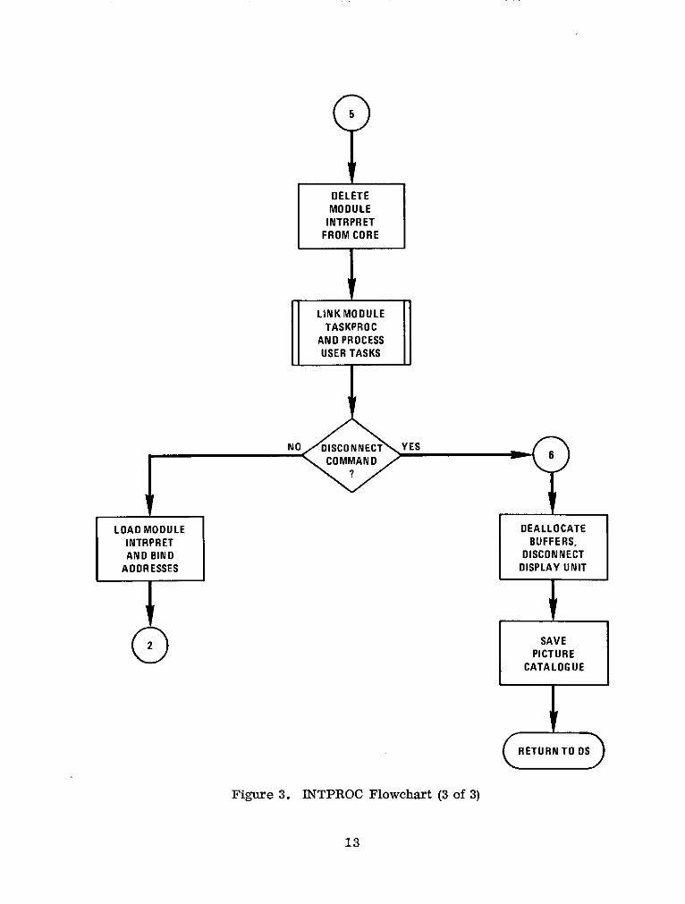
DELETEMODULEINTRPRET
FROM CORE
LINK MODULETASKPROC
AND PROCESSUSER TASKS
NO DISCONNECT YESCOMMAND
LOAD MODULE DEALLOCATE
INTRPRET BUFFERS,AND BIND DISCONNECT
ADDRESSES DISPLAY UNIT
2 SAVEPICTURE
CATALOGUE
RETURN TO OS
Figure 3. INTPROC Flowchart (3 of 3)
13
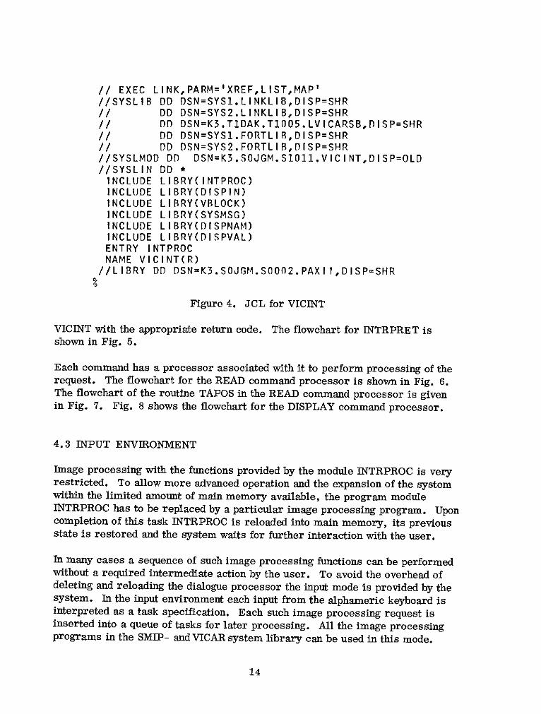
// EXEC LINK,PARM='XREF,LIST,MAP'//SYSLIB DD DSN=SYS1.LINKLIB,DISP=SHR// DD DSN=SYS2.LINKLIB,DISP=SHR// DD DSN=K3.T1DAK.T1005.LVICARSB,D ISP=SHR// DD DSN=SYS1.FORTLIB,DISP=SHR// DD DSN=SYS2.FORTLIB,DISP=SHR//SYSLMOD DD DSN=K3.SOJGM.S111.VICINT,DISP=OLD//SYSLIN DD *INCLUDE LIBRY(INTPROC)INCLUDE LIBRY(DISPIN)INCLUDE LIRRY(VBLOCK)INCLUDE LIBRY(SYSMSG)INCLUDE LIBRY(DISPNAM)INCLUDE LIBRY(DISPVAL)ENTRY INTPROCNAME VICINT(R)
//LIBRY DD DSN=K3.SOJGM.S0002.PAXII,DISP=SHR
Figure 4. JCL for VICINT
VICINT with the appropriate return code. The flowchart for INTRPRET isshown in Fig. 5.
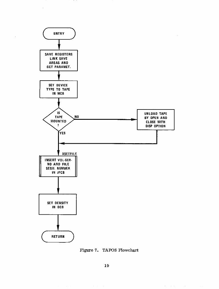
Each command has a processor associated with it to perform processing of therequest. The flowchart for the READ command processor is shown in Fig. 6.The flowchart of the routine TAPOS in the READ command processor is givenin Fig. 7. Fig. 8 shows the flowchart for the DISPLAY command processor.
4.3 INPUT ENVIRONMENT
Image processing with the functions provided by the module INTRPROC is veryrestricted. To allow more advanced operation and the expansion of the systemwithin the limited amount of main memory available, the program moduleINTRPROC has to be replaced by a particular image processing program. Uponcompletion of this task INTRPROC is reloaded into main memory, its previousstate is restored and the system waits for further interaction with the user.
In many cases a sequence of such image processing functions can be performedwithout a required intermediate action by the user. To avoid the overhead ofdeleting and reloading the dialogue processor the input mode is provided by thesystem. In the input environment each input from the alphameric keyboard isinterpreted as a task specification. Each such image processing request isinserted into a queue of tasks for later processing. All the image processingprograms in the SMIP- and VICAR system library can be used in this mode.
14

ENTRY
MODULE INTRPRETSCANNER
DISPLAYINPUT STRINGON SCREEN
DELIMITERS: b
INITIALIZEPOINTERS TO IN LEGAL CHAR.: b = ( ) + - ' %& OUT BUFFER S . * >
CLEAR OUT BUFFER
GET NEXTCHARACTER
ADVANCE OUTPOINTER TONEXT FIELD
YES IS ITLAST CHAR.
NO
SEARCH FOR
CHARACTER YES NEXT DELIMITERAINSERT UP TO
8 LEGAL CHARSINTO OUTBUFFER
NO
SEARCH FORs YES NEXT DELIM.
CCONVERT NUMBERATO BINARY AND
INSERT IN OUTBUFNO
YES CHAR LEGALCHARACTER
NO
SYSMSG
MESSAGE:'ILLEGAL
CHARACTER'
RETURNI
Figure 5. INTRPRET Flowchart (1 of 3)
15

INTERPRETER
RESERVE COMMAND PROCESSOR
CHECK IF NAMEALREAOY RE- SET RECORDALREADY RE-
RESERVE YES SERVED,CHECK LENGTHANDCOMMAND IF SPACE AVAIL- INSERT PICTURE2
? ABLE ON VOLUME NAMEINTABLEREQUESTED
NOREAD COMMAND PROCESSOR
CHECK CORRECT DETERMINEIF TRANSFER
FORMAT OF 7 OR 9 TRACK TAPE PICTURE FROM
COMMAND COMMAND MOUNT TAPE & TAPE TO DISK
CHECK IF DISK POSITION TO SET USED-FLAG
SPACE RESERVED FILE SPECIFIED FOR PICTURENAMENO
WRITE COMMAND PROCESSOR
CHECK CORRECT MOUNT 7 OR
WRITE YES FORMAT OF 9 TRACK TAPECOMMAND COMMAND, POSITION AND 2
? CHECK IF PICTURE WRITE PICTURETO BE WRITTEN EXISTS TO TAPE
NODISPLAY COMMAND PROCESSOR
CHECK IF PICTURE TRANSFER PICTURE DETERMINETO BE DISPLAYED TO CORE IF LESS DISPLAY TYPE,
DISPLAY YES EXISTS, IF AN- 200 x 200 SET GET DISPLAYCOMMAND OTHER PICTURE SIZE-FLAG FOR PARAMETERS,
? WAS MODIFIED TRANSFORMATION BUILD DISPLAYIN CORE RETURN ROUTINES FILE WITH
NOSET COMMAND PROCESSOR
GET DISPLAY APPROPRIATEPARAMETERS TRANSFORMATIONSET YES ROUTINE AND
COMMAND AND INSERT DISPLAY PICTUREIN APPROPRIATE
TABLE HISTOGRAM ORLABEL
NOTHRESHOLD COMMAND PROCESSOR
CREATE ATHRESHOLDED
THRESHOLD YES PICTURE WITHCOMMAND GREYLEVELS
? BY SETCOMMAND
NOSAVE COMMAND PROCESSOR
CHECK IF NEWPICTURE NAME
SAVE YES RESERVED.COMMAND COPY PICTURE 0 2
FROM CORETO DISK
NO
Figure 5. INTRPRET Flowchart (2 of 3)
16

3
TASK SPECIFICATION PROCESSOR
CHECK IF CORRECTCHECK IF IINPUT YES TASK SPECIFI- AND OUTPUTMODE CATION, CHECK IF PICTURES
? TASK IN LIBRARY SERVED, INSERTTASK INTO UEE
NO
E TASKS COMMAND PROCESSOR
DISPLAY TASKSTASKS YES IN INPUT
COMMAND QUEUE ONSCREEN OF 2250
NO FREE COMMAND PROCESSOR
DELETE PICTUREFREE YES NAME FROM
COMMAND TABLE,RETURN? DISK SPACE TO
FREE POOL
EXECUTE COMMAND PROCESSOR
CLOSE INPUTEXECUTUE YES QUEUE FILE,COMMAND RESET QUEUE
? POINTER, DISPLAYEXECUTION MESS.NONO DISCONNECT COMMAND PROCESSOR
DISCONNECT YES CLOSE INPUT RETURN2COMMAND QUEUE FILE
NO EXIT COMMAND PROCESSOR
EXIT YES CLOSE INPUTCOMMAND QUEUE FILE
NO
SYSMSG
MESSAGE:'INVALID 2COMMAND'
Figure 5. INTRPRET Flowchart (3 of 3)
17

ENTRY
SYMSG
NAME MESSAGE:IN NO I 'PICTURE
2CHECK CORRECT
FORMAT OFCOMMAND, 1 TAPIOSET TAPEFORMAT PERFORM
PICTURETRANSFER
SYSMSG FROM TAPETO DISK.
IS MESSAGE:FILE # NO 'FILE #NEG.'
CORRECT OR 'SAME FILE? CANNOT BE READ'
SET INITIALI-+ YES ZATION FLAG
SET 7 OR 9TRACK TAPE
TAPE NO SET NEW TAPEMOUNTED W VOL-SER RETURN
< ? NUMBER
TAPOS
UNLOAD OLDTAPE, MOUNT
NEW TAPE,POSITION TO
FILE SPEC.
Figure 6. READ Command Processor Flowchart
18
SAVE REGISTERSLINK SAVE
AREAS ANDGET PARAMET.
SET DEVICETYPE TO TAPE
IN MCB
Is UNLOAD TAPETAPE ,NO BY OPEN AND
MOUNTED CLOSE WITHDISP OPTION
YES
XSETFILE
INSERT VOL-SER-NO AND FILE
SEQU. NUMBERIN JFCB
SET DENSITYIN DCB
RETURN
Figure 7. TAPOS Flowchart
19
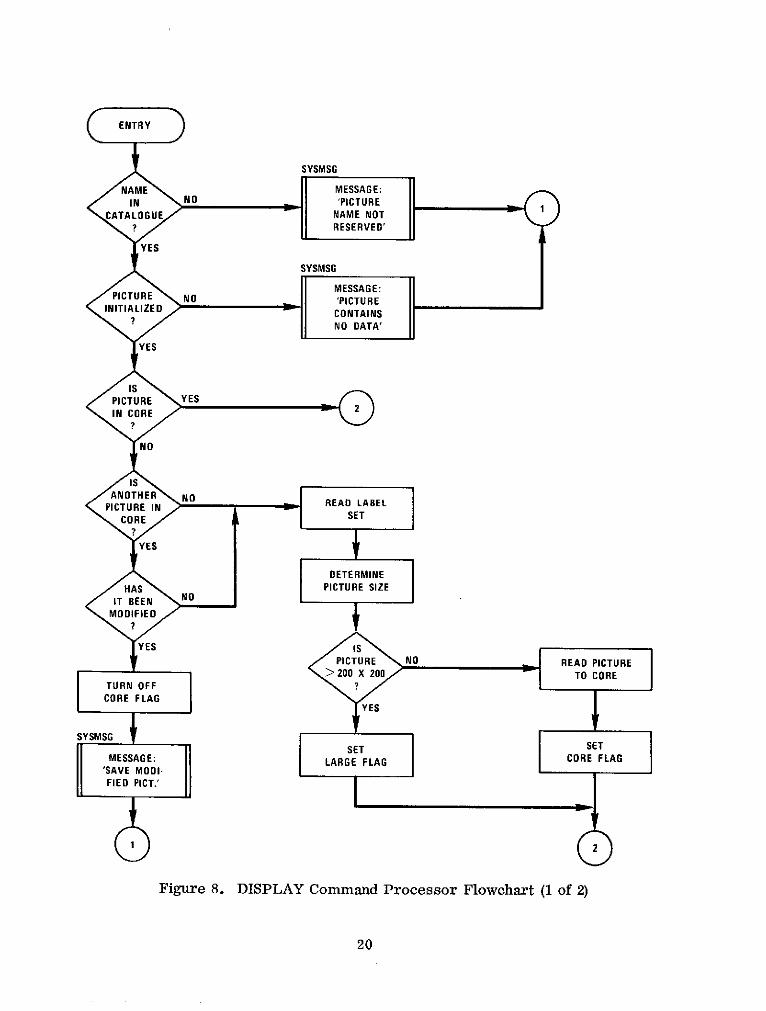
ALIZE D NTRYCONTAINS
SYSMSG
NAME \ I MESSAGE:
IN NO NO DATA'RE
CATALOGUE I NAME NOT?/I RESERVED'
YES
SYSMSG
MESSAGE:PICTURE NO 'PICTURE
INITIALIZED? NO DATA'
YES
isPICTURE \YESIN CORE
NO
isANOTHER NO READ LABEL
PICTURE IN SETCORE SET
YES
DETERMINEHAS PICTURE SIZE
NOIT BEEN NO
MODIFIED
YES IsPICTURE NO READ PICTURE
> 200 X 200 TO CORETURN OFF ?
CORE FLAGYESYES
SYSMSGSET SET
MESSAGE: LARGE FLAG CORE FLAG'SAVE MODI-FIED PICT.'
Figure 8. DISPLAY Command Processor Flowchart (1 of 2)
20

2
PICTURE YES DISPLAY NOPLAY PARAMETERS
SPEC.
NO YES PICTURPICOSP
PICTUREPROCESS TRANSFOR-DISPLAY : MATION AND
PARAMETERS DISPLAYROUTINES
HISTOGRAM YES DISPLAY NO
? SPEC.
SHISTOG
HISTOGRAMDISPLAY TRANSFORM.PARAMS AND DISPLAY
ROUTINES
DOCUM
YES LABELLABEL DISPLAY
'INVALIDDISPLAY
COMMAND'
RETURN
Figure 8. DISPLAY Command Processor Flowchart (2 of 2)
21
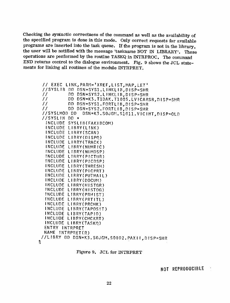
Checking the syntactic correctness of the command as well as the availability ofthe specified program is done in this mode. Only correct requests for availableprograms are inserted into the task queue. If the program is not in the library,the user will be notified with the message 'taskname NOT IN LIBRARY'. Theseoperations are performed by the routine TASKQ in INTRPROC. The commandEND returns control to the dialogue environment. Fig. 9 shows the JCL state-ments for linking all routines of the module INTRPRET.
// EXEC LINK,PARM='XREF,LIST,MAP,LET'//SYSLIB DD DSN=SYS1.LINKLIB,DISP=SHR// DD DSN=SYS2.LINKLIB,DISP=SHR// DD DSN=K3.T1DAK.T1005.LVICARSB,DISP=SHR// DD DSN=SYS1.FORTLIB,DISP=SHR// DD DSN=SYS2.FORTLIB,DISP=SHR//SYSLMOD DD DSN=K3.SOJGM.SlO11.VICINT, DISP=OLD//SYSLIN DD *INCLUDE SYSLIB(FAKIBCOM)INCLUDE LIBRY(LINK)INCLUDE LIRRY(SCAN)INCLUDE LIBRY(DISPQ)INCLUDE LIRRY(TRACK)INCLUDE LIBRY(NUMRIC)INCLUDE LIBRY(NUMDSP)INCLUDE LIBRY(PICTUR)INCLUDE LIBRY(PICDSP)INCLUDE LIRRY(THRESH)INCLUDE LIBRY(PICPRT)INCLUDE LIRRY(PUTMAIL)INCLUDE LIBRY(DOCUM)INCLUDE LIBRY(HISTGR)INCLUDE LIBRY(HISTOG)INCLUDE LIRRY(PRHIST)INCLUDE LIRRY(PRTITL)INCLUDE LIBRY(PRCHK)INCLUDE LIBRY(TAPOSIT)INCLUDE LIBRY(TAPIO)INCLUDE LIBRY(CHCKRT)INCLUDE LIBRY(TASKQ)ENTRY INTRPRETNAME INTRPRET(R)
//LIBRY DD DSN=K3.SOJGM.S0002.PAXII,DISP=SHR
Figure 9. JCL for INTRPRET
NOT REPRODUCIBLE
22
4.4 TASK PROCESSING ENVIRONMENT
The tasks waiting in the input queue are processed in the task processing environ-ment. Processing is started with the EXECUTE command. The module INTR-PRET is deleted from core and the module TASKPROC is loaded and receivescontrol. TASKPROC is a modified version of the module VMJCPHAS in theVICAR system. It reads a task from the input queue and processes its param-eters and labels. Parameters for a task are submitted in free-form format andmay be in one of several types (Integer, Real, Alphameric, Hexadecimal, Lite-ral). The parameters are stored in the task queue in their original EBCDICform. TASKPROC translates all parameters to an internal computer representa-tion which the processing programs can utilize. The translated parameters arewritten temporarily into the disk data set VSYSOO. Image processing programsobtain these parameters by calling the routine PARAM.
Image processing programs are written using the data set reference numbers 2to 11 for input data sets and the data set reference numbers 1 and 12 to 14 foroutput data sets. TASKPROC initializes the MCB's in VICINT and establishesthereby the linkage between these data set reference numbers and a specific dataset or device. It builds also a table with the task name which is later used toload the particular image processing program into the main memory. Then theimage processing program is fetched from the library, replaces TASKPROC incore and starts processing.
The processing programs, in general, expect a standard data format for all in-put and output data sets. This consists of a label set followed by a number ofdata records. Normally TASKPROC copies the label set from the primaryinput data set to any specified output data sets. The system label record is up-dated. If the programmer has specified optional user labels to be added, TASK-PROC adds these to the label set on the output data sets. This automatic labelprocessing is suppressed if the first character in the taskname is a V.
In addition, VMJC positions all input and output data sets to a point just prior tothe first data record. An image processing program does, therefore, not haveto skip the label records. Upon completion of a task, TASKPROC is reloaded andthe next task is initiated. When the last task from the queue has been completed,the dialogue module INTRPRET is loaded into core, its previous state is restoredand the system waits for further requests to process. This is indicated with anaudible alarm and the display of a cursor in the lower left corner of the screen.Fig. 10 lists the JCL statements for linking TASKPROC and putting it into thelibrary.
23

// EXEC ASMG//SYSIN DD DSN=TASKPROC.SOJGM,UNIT=2400,LABEL=(4,SL,, IN),// VOL=SER=Z1610,DISP=(OLD,PASS),DCB=(RECFM=FB,LRECL=80,BLKSIZE=3200// EXEC LINK,PARM='XREF,LIST,MAP,LET'//SYSLIB DD DSNAME=SYS1.LINKLIB,DISP=SHR// DD DSNAME=SYS2.LINKLIB,D ISP=SHR// DD DSN=K3.T1DAK.T1005.LVICARSB,DISP=SHR// DD DSN=SYS1.FORTLIR,DISP=SHR//SYSLMOD DO DSN=K3.SOJGM.S1011.VICINT,DISP=OLD//OBJECT Do *INCLUDE LIBRY(SYSMSG)ENTRY VMOD03NAME TASKPROC(R)
//LIBRY DD DSN=K3.SOJGM.S0002.PAXIIDISP=SHR
Figure 10. TASKPROC JCL
4.4.1 Task Characteristics
Each image processing task involves execution of a program which must existin the SMIPS library (data set name K3. SOJGM. S1011. VICINT) or in the VICARlibrary. The programs may be written either in assembly language or FORTRANIV and may include any number of subroutines. All features of these languagesmay be used with the exception that for input/output of pictorial data the FOR-TRAN I/O statements READ and WRITE and the assembly I/O macros shouldnot be used. The application programs communicate with the data managementfacilities of OS/MVT through the I/O handler in VICINT. This routine super-vises all the I/O operations of the application program. Up to 14 simultaneousI/O requests are supported and the processing of any direct access or tape datafile may be either sequential or random.
Application programs are required to open data sets prior to use. The programmay close its data sets. If not, the system will automatically close any opendata sets at the end of the task. SMIPS uses the VICAR I/O routines whichare described in [ 31. FORTRAN application programs may be written in twoforms:
1. The FORTRAN program is coded as a subroutine with no arguments. Inthis case no FORTRAN I/O statements are allowed and the program hasto use the PRINT routine of VICAR for printing on the high speed printer.Linkage-editing of the program module should include the VICAR rou-tine FAKIBCOM. This routine provides some service functions whichare normally handled by the IBM routine IBCOM#. IBCOM# is a verycomplex program which handles FORTRAN input/output control, program
24

linking, library routine error handling and program termination at acost of over 10 K bytes of core. FAKIBCOM provides IBCOM# initiali-zation, library routine error handling and program exits at a cost ofonly 200 bytes of core.
2. The FORTRAN program uses the FORTRAN I/O statements. In thiscase the program has to be written as a main program and FAKIBCOMshould not be included in linkage-editing. IBCOM# will be automaticallylinked.
4.4.2 Communication between SMIPS and Application Programs
The communication between a task program and the system is accomplished witha transfer vector. The transfer vector provides the entry points to the I/O han-dler and to the image display facilities provided by VICINT. The routine LIN-KUSER which builds the transfer vector and provides the addresses of the entrypoints should be included when linking the program module. This routine re-ceives control when execution of an image processing task is started, binds theaddresses in the transfer vector and passes control to the program. Applicationprograms should exit with CALL END which will assure the continuation of taskprocessing.
There are two sources of input to an application program, the input label and in-put parameters. The input label contains in word 9 the number of lines in thepicture and in word 10 the number of bytes in one line. The input parametertable is placed by TASKPROC into the data set VSYSOO. By a call to PARAM inthe application program, the I/O handler reads the parameter table into the buf-fer designated by the program. The parameter table is comprised of two sec-tions, (1) system parameters and (2) user parameters. The first 10 words of theparameter table (Fig. 11) are reserved for system parameters. The first fourwords contain binary integers representing the output picture dimensions. Thisdata are taken from the size field in the task specification. The fifth and sixthwords are binary integers representing the input picture dimensions. Thesedata are taken from the input label. The seventh and eighth word contain thenumber of input and output data sets for this task respectively. The tenth wordcontains the length of the parameter table in full words.
4.4.3 Communication between Application Programs
Application programs cannot only receive the parameter table provided by thesystem but they may also access parameters generated by another applicationprogram. Any task is allowed to generate parameters for other tasks. The com-munication problem is solved by a message transfer mechanism. Messages
25

SL (OUTPUT)
SS (OUTPUT)
NL (OUTPUT)
NS (OUTPUT)
SYSTEM NL (INPUT)
PARAMETERS NS (INPUT)
NI
NO
LENGTH (WORDS)
USERPARAMETERS
Figure 11. Parameter Table
(mail) are put into a circular list by the sending task and picked up from the listby the receiving task.
The sending task requests a mail block, puts its name and the name of the re-ceiver into the block as well as the length of the mail and the mail itself. Acall to PUTMAL inserts the mail block into the list. The receiving task whichcan only proceed with the information from a certain sender inquires the list bycalling the routine GETMAL. If mail for the task coming from the specifiedsender is found, GETMAL transfers the information to a specified buffer. Other-wise, the task cannot proceed and returns control with an appropriate message.Some tasks may continue processing with default parameters. The format ofthe mail block is shown in Fig. 12.
SENDER NAME
RECEIVER NAME
NUMBER OFWORDS IN MAIL
MAILINFORMATION
Figure 12. Mail Block Format
26
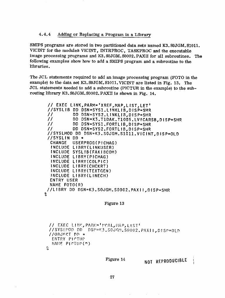
4.4.4 Adding or Replacing a Program in a Library
SMIPS programs are stored in two partitioned data sets named K3. SOJGM. S1011.VICINT for the module VICINT, INTRPROC, TASKPROC and the executableimage processing programs and K3. SOJGM. S0002. PAXII for all subroutines. Thefollowing examples show how to add a SMIPS program and a subroutine to thelibraries.
The JCL statements required to add an image processing program (FOTO in theexample) to the data set K3. SOJGM. S1011.VICINT are listed in Fig. 13. TheJCL statements needed to add a subroutine (PICTUR in the example) to the sub-routing library K3. SOJGM. S0002. PAXII is shown in Fig. 14.
// EXEC LINK,PARM='XREF,MAP,LIST,LET'//SYSLIB DD DSN=SYS1.LINKLIB,DISP=SHR// DD DSN=SYS2.LINKLIB,DISP=SHR// DD DSN=K3.T1DAK.T1005.LVICARSB,DISP=SHR// DD DSN=SYS1.FORTLIB,DISP=SHR// DD DSN=SYS2.FORTLIB,DISP=SHR//SYSLMOD DD DSN=K3.SOJGM.S1011.VICINT,DISP=OLD//SYSLIN DD *CHANGE USERPROG(PICMAG)INCLUDE LIBRY(LINKUSER)INCLUDE SYSLIB(FAKIBCOM)INCLUDE LIBRY(PICMAG)INCLUDE LIBRY(COLPIC)INCLUDE LIBRY(CHCKRT)INCLUDE LIBRY(TEXTGEN)INCLUDE LIBRY(LINECH)ENTRY USERNAME FOTO(R)
//LIBRY DD DSN=K3.SOJGM.S0002.PAXII,DISP=SHR
Figure 13
// EXEC LIN, PARM='L'CAI HAiP, LIST'//SYSI MOD DD DSt'=K3.SOJ,1. S0002.PAXI I,DISP=OLP//ORJFCT DP *
ENTRY PrTtlPNAIIE PIrTLIP()
Figure 14 NOT REPRODUCIBLE
27
5. DATA ORGANIZATION IN SMIPS
5.1 DATA STRUCTURES
For the user of an image processing system the pictoral information has to bestructured in terms of his terminology. This information is converted to anotherform for storage and processing by the computer. In a computer system the in-formation is usually structured in files, records and fields. This section reviewsbriefly some operations on data structures and describes the data organizationin the SMIP system.
A record is a collection of information; it is divided into fields. In SMIPS animage line is treated as a record of variable length. All fields of a record areof equal length (byte, halfword, fullword, doubleword) and hold one picture ele-ment (1 pixel). A file (data set) is a collection of records. In SMIPS a pictureis represented by one file. Picture files have a sequential organization. Ablock is the amount of information transferred between an I/O device and memoryduring one I/O operation. Blocking, the storing of a number of records in oneblock, is used in SMIPS to save space and computer time.
Each picture existing in the system has location, name and value as attributes.Each of these elements is structured and there exist relations between them.There are three sets known to the system.
N set of names
L set of locations
V set of values
L, the set of physical locations, is in one to one correspondence with N.
Name Space
The name of a picture is the attribute which is given to it when it is created. Thename is unique; at the same time several pictures with the same name cannotexist.
To access a picture by its name a relation between the name and the location ofthe picture (the table of contents) has to be established. This relation is calledthe catalogue of picture names.
cataloguename space : table of contents
28
Another role of the catalogue is to determine the uniqueness of the names.Upon creation of a new picture name the catalogue is consulted to determine ifa picture with the same name already exists. A name is a string of alphamericcharacters beginning with a letter and is created by the user (external name).The system then automatically assigns an internal name to the picture.
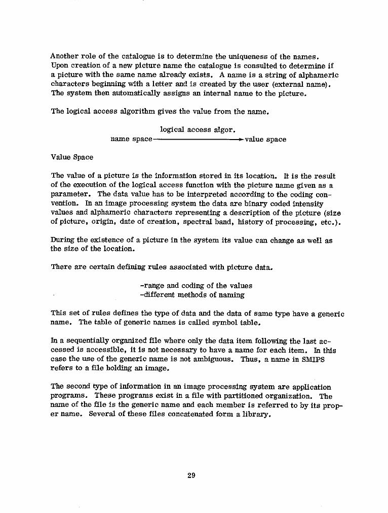
The logical access algorithm gives the value from the name.
logical access algor.name space - value space
Value Space
The value of a picture is the information stored in its location. It is the resultof the execution of the logical access function with the picture name given as aparameter. The data value has to be interpreted according to the coding con-vention. In an image processing system the data are binary coded intensityvalues and alphameric characters representing a description of the picture (sizeof picture, origin, date of creation, spectral band, history of processing, etc.).
During the existence of a picture in the system its value can change as well asthe size of the location.
There are certain defining rules associated with picture data.
-range and coding of the values-different methods of naming
This set of rules defines the type of data and the data of same type have a genericname. The table of generic names is called symbol table.
In a sequentially organized file where only the data item following the last ac-cessed is accessible, it is not necessary to have a name for each item. In thiscase the use of the generic name is not ambiguous. Thus, a name in SMIPSrefers to a file holding an image.
The second type of information in an image processing system are applicationprograms. These programs exist in a file with partitioned organization. Thename of the file is the generic name and each member is referred to by its prop-er name. Several of these files concatenated form a library.
29
5.2 OPERATIONS ON THE DATA STRUCTURES
Five sets have been defined:
L set of locations
N set of names
NG set of generic names
V set of values
0 set of undefined values
The following operations on the data structures representing these sets are usedin SMIPS:
1. Creation of a pictureThe creation consists of three steps:
a) Allocation (0 - L)Find a free place in the table of contents for the disk on which spacefor the picture is to be allocated. The size is furnished by the sym-bol table. Allocation of disk space for SMIPS images is accomplishedby the operating system in a separate job (ALLOCATE).
b) Naming (0 - N)The picture name is specified (created) by the user with the RE-SERVE command. A name already used for another picture is re-fused. The RESERVE command allows allocation and naming at thesame time. In the OS/360 operating system dynamic allocation ofdisk space is not possible. Therefore, the allocation of the diskspace used for storing images is accomplished in a previous job. TheRESERVE command selects only an area of the preallocated space andassigns a name to it.
c) Initialization (0 -, V)This operation takes place after allocation and naming. In the mean-time, the picture exists but has no value. SMIPS does not allow toaccess a picture before its initialization. Initialization is accom-plished with the READ, SAVE or THRESHOLD commands or as out-put of an image processing task.
2. Logical access (N -V)Logical access is the product of localization (N - L) and physical ac-cess (L - V). These operations are performed by SMIPS routines andthe operating system.
30

3. Suppression of a pictureThe suppression of a picture consists of:
a) Deallocation (L -+ 0)The space occupied by the picture is returned to the list of availablespace.
b) Unnaming (N - 0)The picture name referred to is deleted from the catalogue. Thisname could be used to name another picture.
These operations are accomplished with the FREE command.
Access to image processing programs in the library is entirely accomplished byfunctions of the operating system.
5.3 INTERFACE SMIPS TO OS/360
Data manipulated by OS are called data sets (corresponding to a file), theirsymbol table is constituted by the Data Control Blocks (DCB's). Each data setis located on a volume (disk, tape) and each volume has a table of contents, calledVTOC, associated with it. An element of the VTOC is called a Data Set ControlBlock (DSCB). Pictures are stored in sequential data sets, image processingprograms in partitioned data sets which form the system library.
The DDNAME is the external generic name for a class of data sets, the DCBaddress is used as internal generic name. The Job File Control Block (JFCB)gives the correspondence between DDNAME and the corresponding volume. Dueto the sequential organization of a picture data set there is a one to one corres-pondence between a picture name and the generic name of a data set. Therefore,the correspondence between a picture name and the data set allocated for thatpicture is established in the following way. The index of the picture name inthe catalogue is used to calculate another index for retrieval of the DCB addressfrom the symbol table (see Fig. 15). The same index is inserted in the Main-tenance Control Block (MCB) for the associated logical Data Set Reference Num-ber (DSRN). The DSRN's are used in the I/O calls to the I/O handler.
For image processing programs specified in the input mode, the routine TASKQdetermines the indices from the referenced picture names and passes them toTASKPROC, which in turn inserts the indices into the MCB's. Upon execution,the I/O routines called in the image processing program use these indices in theMCB's to retrieve the associated data sets. Routines doing I/O operations in themodules VICINT and INTRPRET should set themselves the appropriate symboltable indices in the MCB's.
31

CATALOGUE OF SYMBOL TABLEPICTURE NAMES (DCB ADDRESSES) DCB
PICT. NAME A DDNAME
MCB DSRNJFCB
I/OCONTROL
INFORMATIONSMIPS
VOLUME VTOC
DSCB
PICTUREVALUES
Figure 15. Correspondence Picture Name-Picture Values
5.4 DATA MANAGEMENT IN SMIPS
Data management in SMIPS is disk oriented. The display transformation rou-tines and application programs read pictures only from disk and result picturesare written to disk data sets in the standard format. The transfer of picturesbetween magnetic tape and disk data sets has to be explicitly specified by theuser with the READ and WRITE commands respectively. An exception are theapplication programs which produce tapes for the Calcomp plotter and the E. I. S.
32

machine. These programs write their output directly to tape because of thespecial format used.
Before a picture can be used it must have been created in the system. The threesteps of creation (allocation, naming, initialization) are described in section 5.2.A picture can be used if it has been initialized by a READ, SAVE or THRESHOLDcommand or as output picture in an image processing task.
The catalogue of picture names is the field NTABLE in COMMON/LRECL/. Inthe current implementation the catalogue can hold up to 20 picture names. Eachpicture name has several attributes associated with it. The initialization flagwhich indicates if the picture is initialized and the core flag indicating if the pic-ture is in core are contained in the field USFLAG in COMMON/LRECL/. Therecord length (line length) of the picture and the blocksize used to pack severallines into a physical record are contained in the field LRECLS in COMMON/LRECL/. These fields are accessed with the same index as the catalogue.
The RESERVE command inserts the picture name into the catalogue, computesthe blocksize and inserts record length (equal to NS) and blocksize into the fieldLRECLS. The FREE command deletes the picture name from the catalogue andsets the flags, record length and blocksize to zero. The released space can thenbe allocated to another picture.
The INPUT/OUTPUT handler is a multientrant part of the core-resident moduleVICINT. It consists of a set of routines, callable from FORTRAN and assemblyprograms, that provide the interface between the image processing programs andthe data management of OS/MVT. The Basic Sequential Access Method (BSAM)is used. The I/O handler supports input/output operations and other data man-agement functions like opening, closing and double buffering of data sets. Theseprocedures are controlled by Maintenance Control Blocks (MCB's). There is anMCB for each data set. An MCB contains fields for control information such as:
data set opened or closed
single or double buffer
input or output data set
device type (tape or disk)
I/O status
current record number pointer
blocking factor
number of labels
33

There are also fields to keep track of buffer addresses and lengths and for theindex in the symbol table (DCB Table). Before opening a data set, record lengthand blocksize are automatically copied from the table LRECLS into the corre-sponding DCB. This is necessary because the user can allocate the same dataset for pictures of various sizes during a session.
The data set reference number used in the I/O statements specifies which MCBis associated with a data set. Thus, the MCB is the interface between a logicaldata set reference number and a physical device. The I/O handler is a modifiedversion of the VICAR I/O routines which are described in [3].
6. GRAPHIC PROGRAMMING TECHNIQUES
The problem of graphic programming is to find an efficient representation of animage and the relations among its objects in memory. This representation mustpermit the easy manipulation of the represented objects.
Each graphic terminal has its own language which allows to describe the opera-tions necessary to obtain an image on the screen. This is usually a very lowlevel language and it is laborious to write graphic programs with it. The in-struction set is also very limited allowing only to display points, vectors andpossibly characters. It is thus necessary to define a high level graphic languagewhose instruction permits the specification of more general graphic objects andto allow for control of luminosity, density of points, use of light pen etc. . .High level graphic languages have been implemented by embedding in a generalhigh level language [4, 5].
Considering the restricted number of display types in the SMIP system it wasdecided not to implement a high level graphic language but to use the basic ordersand macro-instructions provided for the IBM 2250 display terminal [61. Thisallows to optimize the design for this specific application on a given displayprocessor.
6.1 DEFINITION OF AN IMAGE
The basic images (points, vectors, characters) provided by a graphic terminalare called elements. A graphic object is a set of elements illuminated with thesame intensity. It is obtained with one instruction (e. g. a string of characters).An object can be composed of only one element. A figure is a collection of ob-jects to which a name is assigned.
An image is the set of figures displayed at one instance on the screen. A cer-tain ambiguity seems to exist in the fact that by using the terms figure and image
34

it is not clear if the representation in memory or the display on the screen ismeant. There is virtually no difference between these two notions. In the fol-lowing sections image or figure will be generally used for their representationin memory.
6.2 IMAGE STRUCTURES
The representation of an image has also to express the relations that exist amongthe figures forming an image. Such a representation is called an image struc-ture. A display file is the list of instructions and data of an image. By repeat-edly executing this list, the display processor attempts to maintain a flicker-free picture on the screen of the cathode-ray tube. In such a simple structureeach figure is repeated in the list at each occurrence. If an image has to bemodified the entire display file has to be changed.
An improvement of this technique is the use of structured display files. Herefigures are constructed by subroutines and the display file is organized into atree structure as is shown in Fig. 16. The display processor refreshes thepicture by threading its way through this structure, interpreting the pointers assubroutine calls. Structured display files are more easily modified than the un-structured files, since one element of the display can be modified without dis-turbing the rest. Objects which occur repeatedly can be represented by subrou-tines, and in this way the size of the display file can be reduced. It is also pos-sible to link interrupts, received from a pointing device such as a light pen, tothe appropriate parts of the structure. Structured display files have some draw-backs. They are designed for a specific display device so that refreshing maybe carried out as fast as possible. As a result it is usually very troublesome
IMAGE FIGURES OBJECTS
Figure 16. Structured Display File
35
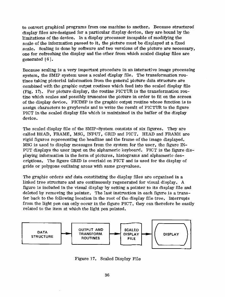
to convert graphical programs from one machine to another. Because structureddisplay files are designed for a particular display device, they are bound by thelimitations of the device. In a display processor incapable of modifying thescale of the information passed to it, the picture must be displayed at a fixedscale. Scaling is done by software and two versions of the picture are necessary,one for refreshing the display and the other from which scaled display files are
generated [6 ].
Because scaling is a very important procedure in an interactive image processingsystem, the SMIP system uses a scaled display file. The transformation rou-tines taking pictorial information from the general picture data structure arecombined with the graphic output routines which feed into the scaled display file(Fig. 17). For picture display, the routine PICTUR is the transformation rou-tine which scales and possibly truncates the picture in order to fit on the screenof the display device. PICDSP is the graphic output routine whose function is toassign characters to greylevels and to write the result of PICTUR to the figurePICT in the scaled display file which is maintained in the buffer of the displaydevice.
The scaled display file of the SMIP-System consists of six figures. They arecalled HEAD, FRAME, MSG, INPUT, GRID and PICT. HEAD and FRAME arerigid figures representing the headline and the frame of the image displayed.MSG is used to display messages from the system for the user, the figure IN-PUT displays the user input on the alphameric keyboard. PICT is the figure dis-playing information in the form of pictures, histograms and alphameric des-criptions. The figure GRID is overlaid on PICT and is used for the display ofgrids or polygons outlining areas with same greyvalues.
The graphic orders and data constituting the display files are organized in alinked tree structure and are continuously regenerated for visual display. Afigure is included in the visual display by setting a pointer to its display file anddeleted by removing the pointer. The last instruction in each figure is a trans-fer back to the following location in the root of the display file tree. Interruptsfrom the light pen can only occur in the figure PICT, they can therefore be easilyrelated to the item at which the light pen pointed.
OUTPUT AND SCALEDDATA TRANSFORM. DISPLAY DISPLAYSTRUCTURE ROUTINES FILE
Figure 17. Scaled Display File
36

The root of the display file tree is shown in Figure 18.
GSRT START REGENERATION TIMER2
0 NOT USED
GPDP DISABLE LIGHT PEN DETECT8
HEAD
12
FRAME
16MSG
20INPUT
24
GRID28
GESD ENABLE LIGHT PEN DETECT30
PICT34
Figure 18. Display File Tree
6.3 DESCRIPTION OF THE IBM 2250 DISPLAY UNIT [81
The 2250 is organized around a cathode ray tube on which graphic and alphanu-meric information is displayed, thereby providing visual communication betweenthe computer and its user. Keyboards and light pen provide a means of enteringand modifying information. The 2250 equipped with the absolute vector graphicsfeatures can display points and vectors at any angle on a raster of 1024 by 1024points. Points plotted four or more raster units apart can be distinguished asdiscrete points. A standard character set of 63 alphabetics, numerics andspecial symbols is provided by the character generator. 74 basic size characterscan be displayed in each of 52 lines. The distance between the center of twocharacters is 56 raster units, the distance between two lines is 80 raster units.The display area is 12 inches by 12 inches. The alphameric keyboard is a type-writer like keyboard with which the user can compose commands for entry intothe system. 44 keys and a space bar provide a selection of 63 characters. Inaddition there are the keys:
37

SHIFT allows selection of the upper character in a dual char-acter key.
ALT unlocks the keyboard when depressed with SHIFT.
END signifies the end of manually entering alphameric char-acters from the keyboard. When depressed with ALT itinitiates the transfer of the character string entered tomain memory.
SPACE advances the cursor one buffer position.
BACKSPACE backspaces the cursor one buffer position.
Depression of a character key provokes insertion of the character into the buf-fer position indicated on the screen by the cursor symbol. The cursor symbolis a dash displayed beneath the character position at which the character selectedat the keyboard will be placed. If the cursor is not displayed, characters cannot be inserted.
The programmed function keyboard consists of 32 keys and light indicators. Thefunction of each key is program defined and is identified to the user by the over-lay. When a key is depressed, an attention signal is sent to the CPU and the com-puter acts as directed by the subroutine associated with the selected key. Theindicators can be lit or extinguished under program control and inform the userthat certain keys can be activated.
The light pen enables the user to communicate with the computer by pointing apen-like device at a portion of the displayed image. Once the light pen is prop-erly positioned, the user depresses the light pen to the screen to close thespringloaded tip switch. This causes an attention signal sent to the CPU and thesystem acts on the identified portion of the display as determined by the associ-ated subroutine.
The visible display on the CRT is produced by action of an electron beam causingthe phosphor coating to glow briefly. The glow fades within a fraction of a sec-ond, therefore, the display must be regenerated at such a rate that it appearssteady to the observer. The regeneration rate is variable up to a rate of 40 cps(25 ms) dependant on the amount of information displayed. If the time requiredto execute a sequence of graphic orders that follow a Start Regeneration order(GSRT) exceeds 25 ms, the display will flicker. A suitable display is obtainedwith a regeneration rate of 30 to 40 cps.
The 2250 disposes of a local buffer to store images for display regeneration.This enables the 2250 to operate concurrently with the computer system freeing
38
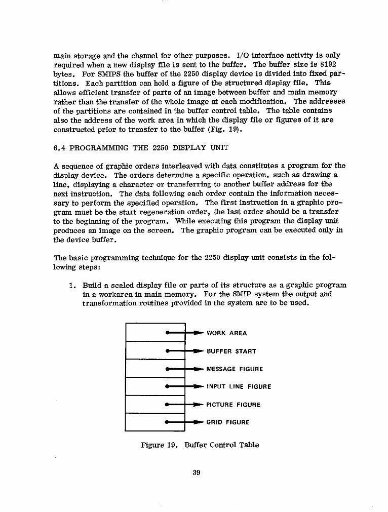
main storage and the channel for other purposes. I/O interface activity is onlyrequired when a new display file is sent to the buffer. The buffer size is 8192bytes. For SMIPS the buffer of the 2250 display device is divided into fixed par-titions. Each partition can hold a figure of the structured display file. Thisallows efficient transfer of parts of an image between buffer and main memoryrather than the transfer of the whole image at each modification. The addressesof the partitions are contained in the buffer control table. The table containsalso the address of the work area in which the display file or figures of it areconstructed prior to transfer to the buffer (Fig. 19).
6.4 PROGRAMMING THE 2250 DISPLAY UNIT
A sequence of graphic orders interleaved with data constitutes a program for thedisplay device. The orders determine a specific operation, such as drawing aline, displaying a character or transferring to another buffer address for thenext instruction. The data following each order contain the information neces-sary to perform the specified operation. The first instruction in a graphic pro-gram must be the, start regeneration order, the last order should be a transferto the beginning of the program. While executing this program the display unitproduces an image on the screen. The graphic program can be executed only inthe device buffer.
The basic programming technique for the 2250 display unit consists in the fol-lowing steps:
1. Build a scaled display file or parts of its structure as a graphic programin a workarea in main memory. For the SMIP system the output andtransformation routines provided in the system are to be used.
WORK AREA
BUFFER START
MESSAGE FIGURE
INPUT LINE FIGURE
PICTURE FIGURE
GRID FIGURE
Figure 19. Buffer Control Table
39

2. Transfer the display file to the appropriate location in the 2250 buffer.
3. Start execution of the regeneration sequence.
Commands from the user are assembled and edited in the buffer. On requestthey are transferred to main memory for further processing. The graphic ordersand the instructions to initiate the data transfer between main memory and de-vice buffer are listed in [61.
6.5 COMMUNICATION HANDLING
Communication with the system is initiated by depressing keys on the keyboardsor by touching a part of a display with the light pen. Any of these actions resultsin an attention. The SMIP system provides routines to be entered on receipt ofsuch an attention.
The SMIP system supplies information to the operating system concerning whichroutines are to respond to what types of attentions. The operating system de-tects the occurrence of an attention, interrupts the currently processing routineand passes control to the appropriate attention handling routine. After this rou-tine has performed its function, control returns to the interrupted routine. At-tentions for which no attention handling routine is available are ignored.
Each SMIPS routine which has to process communications with the user is de-signed according to the following rules:
1. Define the attention handling capabilities of the routine to the operatingsystem. In particular specify the attention handling routines and thetypes of attentions to be serviced by these routines. Define a communi-cation area in main storage to which the operating system will pass at-tention information (type of attention, key number, coordinates of lightpen position).
2. Enable operating system references to the attention routines.
3. Wait for specific attentions.
4. Upon return from the attention handling routines disable operating sys-tem references to these routines.
5. Process the attention information in the communication area.
6. Go to step 2 if no exit condition was specified in step 5.
The only function of the attention handling routines is to notify the operating sys-tem on completed attention processing. The actual processing is performed in
40

the main routine rather than in the attention handling routine to facilitate com-
munication between various parts of the system.
6.6 COMMUNICATION WITH THE 2250 DISPLAY UNIT
All system routines and application programs are allowed to access the displayunit and to send figures to its display file. Communication with the 2250 is es-
tablished with the Graphic Control Block (GRCBLK). The GRCBLK is built bythe routine DISPIN in VICINT. It contains the address of the DCB for the 2250display unit (DDNAME = GRAVIC), the address of the Data Event Control Block
(DECB) for I/O operations of the 2250, the address of the Output Area ControlBlock (OACB) used for I/O operations, the address of a 100 word work area
used by problem oriented graphic routines and the address of the buffer control
table (Fig. 20). Any routine which is not in the core resident module VICINT
establishes communication with the 2250 by a CALL GRCBLK which returns
the address of GRCBLK in register 1 from the transfer vector.
7. LIGHT PEN TRACKING
The SMIP System provides for a light pen tracking capability. Light pen tracking
could be used to outline areas by border detection and to produce maps from thepictorial data. Basically connected regions in form of polygons are generated on
the screen with the aid of the light pen. The coordinates of the corner points ofeach polygon are recorded in a data structure (a sequential list).
The Depression of key 28 labeled TRACK enables the system for light pen track-ing. The user may now select a picture point with the light pen and then presskey 29 labeled PICK which will trigger the procedure to record the coordinatesof the selected point (Note: if a horizontal or vertical line pattern appears on thescreen, move the light pen slightly perpendicular to the direction of the pattern).
DCB
DECB
OACB
-- N WORK
i W- BTABLE
Figure 20. Graphic Control Block
41

Repetition of this procedure will result in drawing a straight line segment be-tween the current and the previously selected points. The last line segmentdrawn can be removed by pressing key 25 labeled DELETE.
To terminate a polygon and start construction of a new polygon depress key 26.Terminate light pen tracking and return to the normal dialogue mode by depress-ing key 27 labeled NOTRACK.
REFERENCES
[11 Moik, J. G.: Small Interactive Image Processing System (SMIPS), UsersManual. GSFC X-Document X-650-73-283.
[21 Newman, W. M.: A System for Interactive Graphical Programming. Proc.1968 Spring Joint Computer Conference. Thompson Books 1968.
[31 JPL Digital Image Processing System Manual VICAR-Version 3, August1968. Re-order No. 68-369.
[41 Rully, A. D.: A subroutine package for FORTRAN. IBM Systems Journal7(1968), 248-270.
[5] Kulsrud, H. E.: A General-Purpose Graphic Language. Comm. ACM 11,4 (1968), 247-254.
[6] IBM System/360 Operating System: Graphic Programming Services forIBM 2250 Display Unit. Form C27-6909-5.
[71 Newman, W. M.: Display Procedures. Comm. ACM 14, 10(1971), 651-660.
[81 IBM System/360 Component Description: IBM 2250 Display Unit Model 1.Form A27-2701-1.
42