SMALL ENGINE LOAD ESTIMATOR FOR FUEL INJECTION...
45
SMALL ENGINE LOAD ESTIMATOR FOR FUEL INJECTION SYSTEM USING TWO-STAGE NEURAL NETWORK MOHD TAUFIQ BIN MUSLIM A thesis submitted in fulfilment of the requirements for the award of the degree of Doctor of Philosophy (Electrical Engineering) Faculty of Electrical Engineering Universiti Teknologi Malaysia JUNE 2016
Transcript of SMALL ENGINE LOAD ESTIMATOR FOR FUEL INJECTION...

i
SMALL ENGINE LOAD ESTIMATOR FOR FUEL INJECTION SYSTEM
USING TWO-STAGE NEURAL NETWORK
MOHD TAUFIQ BIN MUSLIM
A thesis submitted in fulfilment of the
requirements for the award of the degree of
Doctor of Philosophy (Electrical Engineering)
Faculty of Electrical Engineering
Universiti Teknologi Malaysia
JUNE 2016

iii
ACKNOWLEDGEMENT
First and foremost, I would like to express my greatest gratitude to my
supervisor, Assoc. Prof. Ir. Dr Hazlina Selamat for the guidance and enthusiasm
given throughout the progress of this work. Her patience and continuous support
have greatly helped me in finishing this thesis. I am also very thankful to my co-
supervisors, Assoc. Prof. Engr. Dr Ahmad Jais Bin Alimin for his guidance, advices
and motivation.
My appreciation also goes to my family who has been so tolerant and
supportive all these years. Thanks for their encouragement, love and emotional
supports. Lastly, thanks to my friends and those who directly or indirectly
contributing in any way that help me to complete this research.

iv
ABSTRACT
Most motorcycles in developing countries use carburetor systems as fuel
delivery method especially for models with cubic capacity of less than 350 cc.
However, small gasoline carbureted engines suffer from low operating efficiency,
high fuel consumption and high level of hazardous emissions. In recent years,
Electronic Fuel Injection (EFI) technology has been applied to small engine
motorcycles as well. EFI system has better fuel economy and can reduce harmful
emissions by correctly calculating suitable amount of fuel to be injected into the
combustion chamber. One way to achieve this is by accurately estimate the engine
load by using the in-cylinder Air Mass Flow (AMF) rate of the engine. Most of the
control schemes in modern system either approximate the AMF near the throttle
plate using Mass Air Flow (MAF) sensor or in the intake manifold using Manifold
Absolute Pressure (MAP) sensor. This work presents a more economical approach to
estimate the AMF by using only the measurements of throttle position and engine
speed, that is, without using the MAF sensor or the MAP sensor to estimate the AMF
in intake manifold, resulting in lower implementation cost. The estimation is done
via two-stage multilayer feed-forward neural network with combinations of
Levenberg-Marquardt (LM) algorithm, Bayesian Regularization (BR) algorithm and
Particle Swarm Optimization (PSO) algorithm. Based on the results in 20 runs, the
second variant of hybrid algorithm yields a better network performance with a mean
squared error (MSE) of 1.8308 by estimating the AMF closely to the simulated AMF
values compared to using the first variant of hybrid algorithm (MSE of 2.8906), LM
(MSE of 8.0525), LM with BR (MSE of 3.5657) and PSO (MSE of 133.7900) alone.
By using a valid experimental training data, the estimator network trained with the
second variant of the hybrid algorithm showed the best performance, with MSE of
1.9863, among other algorithms when used in an actual small engine fuel injection
system.

v
ABSTRAK
Kebanyakan motosikal di negara-negara membangun menggunakan sistem
karburator sebagai kaedah penghantaran bahan api terutamanya bagi model kapasiti
enjin kurang dari 350 cc. Walau bagaimanapun, enjin petrol kecil bersistemkan
karburator mempunyai kecekapan operasi yang rendah, penggunaan bahan api yang
tinggi dan tahap pelepasan berbahaya yang tinggi. Dalam tahun-tahun kebelakangan
ini, teknologi Suntikan Bahan Api Elektronik (EFI) telah digunakan untuk enjin
motosikal kecil juga. Salah satu cara untuk mencapainya adalah dengan
menganggarkan beban enjin dengan tepat menggunakan kadar Alir Jisim Udara
(AMF) di dalam silinder enjin. Kebanyakan kaedah dalam sistem moden
menganggarkan AMF berhampiran dengan plat pendikit menggunakan penderia
Jisim Aliran Udara (MAF) ataupun di dalam pancarongga pengambilan dengan
menggunakan penderia Tekanan Mutlak Pancarongga (MAP). Kajian ini
membentangkan satu pendekatan yang lebih menjimatkan untuk menganggar AMF
di dalam pancarongga pengambilan dengan hanya menggunakan ukuran kedudukan
pendikit dan kelajuan enjin, tanpa menggunakan penderia MAF ataupun penderia
MAP yang membawa kepada kos pelaksanan yang rendah. Anggaran dilakukan
melalui dua peringkat jaringan neural berlapis bersuap hadapan dengan gabungan
algoritma Levenberg-Marquardt (LM), algoritma Regularisasi Bayesian (BR) dan
algoritma Pengoptimuman Kerumunan Zarah (PSO) sebagai algoritma latihan.
Berdasarkan keputusan dalam 20 larian, algoritma hibrid yang kedua menghasilkan
prestasi rangkaian yang lebih baik dengan ralat min kuasa dua (MSE) 1.8308 dengan
menganggarkan AMF hampir dengan nilai AMF simulasi berbanding dengan hanya
menggunakan algoritma hibrid yang pertama (MSE 2.8906), LM (MSE 8.0525), LM
bersama BR (MSE 3.5657) dan PSO (MSE 133.7900) sahaja. Jaringan penganggar
yang dilatih dengan algoritma hibrid yang kedua menunjukkan prestasi yang terbaik,
dengan ralat min kuasa dua (MSE) sebanyak 1.9863 berbanding dengan algoritma-
algoritma lain pada sistem suntikan bahan api berenjin kecil yang sebenar.

vi
TABLE OF CONTENTS
CHAPTER TITLE PAGE
DECLARATION ii
ACKNOWLEDGEMENT iii
ABSTRACT iv
ABSTRAK v
TABLE OF CONTENTS vi
LIST OF TABLES x
LIST OF FIGURES xi
LIST OF ABBREVIATIONS xix
LIST OF SYMBOLS xxi
LIST OF APPENDIX xxiv
1 INTRODUCTION 1
1.1 Background of the Study 1
1.2 Problem Statement 7
1.3 Objective of the Study 8
1.4 Scope of the Study 8
1.5 Contribution of the Research 9
1.6 Outline of the Thesis 9
2 LITERATURE REVIEW 10
2.1 Introduction 10
2.2 Single-Cylinder Motorcycle Engines 10
2.2.1 Two-stroke Engine 12
2.2.2 Four-stroke Engine 13
2.2.3 Small Engine Fuel Injection System 15
vii
2.3 Fuel Delivery System 17
2.3.1 Carburettor System 17
2.3.2 Fuel Injection System 18
2.3.2.1 Indirect Injection 22
2.3.2.2 Direct Injection 24
2.4 Review of Fuel Injection Control Schemes 25
2.5 Review of Engine Load Estimation Methods 28
2.5.1 Engine Load Estimation in Commercial Fuel
Injection System 28
2.5.1.1 Air-flow Method 29
2.5.1.2 Speed-Density Method 31
2.5.1.3 Alpha-N Method 31
2.5.2 Engine Load Estimation Methods by Past
Researchers 33
2.5.2.1 AMF Estimation Based on Analytical
Model 34
2.5.2.2 AMF Estimation Based on Empirical
Model 36
2.6 Review of Training Algorithm for Feedforward
Neural Network 37
2.6.1 Levenberg-Marquardt (LM) 38
2.6.2 Bayesian Regularization (BR) 40
2.7 Summary 42
3 METHODOLOGY 44
3.1 Introduction 44
3.2 Engine Air-Mass Flow Rate Estimator 44
3.2.1 Two-Stage Multilayer Feed-Forward Neural
Network as Estimator 45

viii
3.2.2 Proposed Hybrid Training Algorithms
for the AMF Estimator 46
3.3 Data Collection and Training Procedures for the
Estimator 50
3.4 Control Scheme for Testing Estimator Efficiency 53
3.5 Development of the AMF Estimator of a Real
Engine 55
3.5.1 Experimental Setup and Data Collection 56
3.6 Summary 59
4 RESULTS AND DISCUSSION 60
4.1 Introduction 60
4.2 Determination of the Best Network Structure for the
AMF Estimator 60
4.2.1 Selection of the network structure for the
MAP estimator 62
4.2.2 Selection of the network structure for the
MAF estimator 63
4.3 Performance Analysis of the AMF Estimator Using
Different Training Algorithm 65
4.3.1 Performance Analysis on the MAP Estimator 66
4.3.2 Performance Analysis on the MAF Estimator 76
4.4 Estimator Output in Steady-state Condition 87
4.4.1 Using Clean Inputs 87
4.4.2 Using Inputs Incorporated with Noise 90
4.5 Estimator Output in Transient Condition 97
4.5.1 Using Clean Inputs 98
4.5.2 Using Inputs Incorporated with Noise 99

ix
4.6 Analysis of the Estimator Efficiency in a Control
System 103
4.6.1 AFR Response during Steady-state Condition 103
4.6.2 AFR Response during Transient Condition 106
4.7 Analysis of the Estimator Efficiency in a Real Engine 108
4.7.1 Performance Analysis of the MAP Estimator
Using Offline Data 109
4.7.2 MAP Estimator Output in Steady-state Operation 118
4.7.3 MAP Estimator Output in Transient Operation 121
4.8 Comparison of the Results between Simulation and
Experimental 123
4.9 Summary 123
5 CONCLUSION AND FUTURE RECOMMENDATION 125
5.1 Conclusion 125
5.2 Contribution of the Research 128
5.3 Future Recommendations 128
REFERENCES 129
Appendices A 142

x
LISTS OF TABLES
TABLE NO. TITLE PAGE
3.1 List of training algorithms for the estimator network 52
3.2 Specifications of the SYM E-BONUS 110 57
3.3 Set points for data collection 59
4.1 Setting for several networks training 61
4.2 Performance of the first network (MAP estimator) in
20 runs 72
4.3 Performance of the second network (MAF estimator) in
20 runs 84
4.4 MSE of the AMF estimation 90
4.5 MSE of the AMF estimation with noisy input at 4200 rpm 94
4.6 MSE of the AMF estimation during transient operation for
different SNR value at varying throttle angle 102
4.7 MSE of the AFR response in steady-state condition at
3000 rpm and different throttle angle. 105
4.8 MSE of the AFR response in transient condition 107
4.9 Performance of the MAP estimator for the RFIS in 20 runs 115
4.10 MSE of the MAP estimation at different speed and throttle
angle 119

xi
LIST OF FIGURES
FIGURE NO. TITLE PAGE
1.1 Registered motorcycles in year 2010 throughout
the world 1
1.2 Registered vehicles in Malaysia at the end of 2013 2
1.3 Total accumulated registered motorcycles from 2009
until 2013 in Malaysia 3
1.4 Emission and A/F relationship chart for gasoline
engine 4
1.5 Sources of air pollution in Malaysia 6
2.1 Typical SI engine components 11
2.2 The sequence of events that take place in a two-stroke
engine 12
2.3 The sequence of events that take place in a four-stroke
engine 14
2.4 Aftermarket fuel injection kit of small engine 16
2.5 Basic working principle of a carburettor 18
2.6 Structure of FIS 19
2.7 A throttle body injection system 23
2.8 A port fuel injection system 23
2.9 A direct injection system 24
2.10 Conventional control system in FIS 25
2.11 Conventional methods of engine modelling 34
2.12 The structure of multi-layer feed-forward network 38

xii
3.1 The block diagram of the AMF estimator 45
3.2 Two-stage neural network estimator block diagram 46
3.3 The basic flow chart of PSO algorithm 48
3.4 The throttle and intake manifold dynamic model 51
3.5 Reference fuel map for data collection 52
3.6 Block diagram of a fuel rate control system
(a) With the estimator,
(b) With the throttle & manifold model 53
3.7 Internal structure of the controller 54
3.8 Internal structure of mixing and combustion model 55
3.9 Experimental setup for data collection in RFIS 56
3.10 Experimental setup block diagram for data collection
in RFIS 57
3.11 Location of the sensors in the RFIS on
SYM E-BONUS 110 58
4.1 Variation of the network (MAP estimator) test MSE
with the number of hidden neuron of five training
algorithms 62
4.2 Variation of the network (MAP estimator) test MSE
with the number of hidden neuron of four training
algorithms 63
4.3 Variation of the network (MAF estimator) test MSE
with the number of hidden neuron of five training
algorithms 64
4.4 Variation of the network (MAF estimator) test MSE
with the number of hidden neuron of four training
algorithms 64
4.5 Comparison of the first network (LM) output and
simulated MAP as a function of (a) throttle and
(b) speed 67

xiii
4.6 Comparison of the first network (LM+BR) output and
simulated MAP as a function of (a) throttle and
(b) speed 68
4.7 Comparison of the first network (PSO) output and
simulated MAP as a function of (a) throttle and
(b) speed 69
4.8 Comparison of the first network (LM+BR+PSOa) output
and simulated MAP as a function of (a) throttle and
(b) speed 70
4.9 Comparison of the first network (LM+BR+PSOb) output
and simulated MAP as a function of (a) throttle and
(b) speed 71
4.10 Distribution of relative error of the first network
(LM) output 73
4.11 Distribution of relative error of the first network
(LM+BR) output 74
4.12 Distribution of relative error of the first network
(PSO) output 74
4.13 Distribution of relative error of the first network
(LM+BR+PSOa) output 75
4.14 Distribution of relative error of the first network
(LM+BR+PSOb) output 75
4.15 Comparison of the second network (LM) output
and simulated AMF as a function of
(a) throttle, (b) speed, and (c) estimated MAP 77
4.16 Comparison of the second network (LM+BR) output
and simulated AMF as a function of
(a) throttle, (b) speed, and (c) estimated MAP 79
4.17 Comparison of the second network (PSO) output
and simulated AMF as a function of
(a) throttle, (b) speed, and (c) estimated MAP 80

xiv
4.18 Comparison of the second network (LM+BR+PSOa)
output and simulated AMF as a function of
(a) throttle, (b) speed, and (c) estimated MAP 82
4.19 Comparison of the second network (LM+BR+PSOb)
output and simulated AMF as a function of
(a) throttle, (b) speed, and (c) estimated MAP 83
4.20 Distribution of relative error of the second
network (LM) output 84
4.21 Distribution of relative error of the second network
(LM+BR) output 85
4.22 Distribution of relative error of the
second network (PSO) output 85
4.23 Distribution of relative error of the second network
(LM+BR+PSOa) output 86
4.24 Distribution of relative error of the second network
(LM+BR+PSOb) output 86
4.25 Comparison between estimated and simulated AMF at
3500 rpm and 20˚ of throttle angle 88
4.26 Comparison between estimated and simulated AMF at
3500 rpm and 60˚ of throttle angle 88
4.27 Comparison between estimated and simulated AMF at
5500 rpm and 40˚ of throttle angle 89
4.28 Comparison between estimated and simulated AMF at
5500 rpm and 90˚ of throttle angle 89
4.29 Inputs with clean signal (blue) and AWGN with SNR
of 50 dB (red) for (a) 20˚ of throttle angle, and
(b) 4200 rpm of engine speed 91
4.30 Inputs with clean signal (blue) and AWGN with SNR
of 40 dB (red) for (a) 20˚ of throttle angle, and
(b) 4200 rpm of engine speed 91

xv
4.31 Inputs with clean signal (blue) and AWGN with SNR
of 30 dB (red) for (a) 20˚ of throttle angle, and
(b) 4200 rpm of engine speed 92
4.32 Inputs with clean signal (blue) and AWGN with SNR
of 50 dB (red) for (a) 90˚ of throttle angle, and
(b) 4200 rpm of engine speed 92
4.33 Inputs with clean signal (blue) and AWGN with SNR
of 40 dB (red) for (a) 90˚ of throttle angle, and
(b) 4200 rpm of engine speed 93
4.34 Inputs with clean signal (blue) and AWGN with SNR
of 30 dB (red) for (a) 90˚ of throttle angle, and
(b) 4200 rpm of engine speed 93
4.35 Comparison between estimated and simulated AMF at
4200 rpm and 20% of throttle opening with SNR of
50 dB at inputs 94
4.36 Comparison between estimated and simulated AMF at
4200 rpm and 20% of throttle opening with SNR of
40 dB at inputs 95
4.37 Comparison between estimated and simulated AMF at
4200 rpm and 20% of throttle opening with SNR of
30 dB at inputs 95
4.38 Comparison between estimated and simulated AMF at
4200 rpm and 90% of throttle opening with SNR of
50 dB at inputs 96
4.39 Comparison between estimated and simulated AMF at
4200 rpm and 90% of throttle opening with SNR of
40 dB at inputs 96
4.40 Comparison between estimated and simulated AMF at
4200 rpm and 90% of throttle opening with SNR of
30 dB at inputs 97
4.41 A varying throttle input in transient condition 98
4.42 Comparison between estimated and simulated AMF at
3200 rpm during transient condition 99

xvi
4.43 Inputs with clean signal (blue) and AWGN with SNR
of 50 dB (red) for a varying throttle angle, and
3200 rpm of engine speed 99
4.44 Inputs with clean signal (blue) and AWGN with SNR
of 40 dB (red) for a varying throttle angle, and
3200 rpm of engine speed 100
4.45 Inputs with clean signal (blue) and AWGN with SNR
of 30 dB (red) for a varying throttle angle, and
3200 rpm of engine speed 100
4.46 Comparison between estimated and simulated AMF at
3200 rpm during transient condition with SNR of
50 dB at inputs 101
4.47 Comparison between estimated and simulated AMF at
3200 rpm during transient condition with SNR of
40 dB at inputs 101
4.48 Comparison between estimated and simulated AMF at
3200 rpm during transient condition with SNR of
30 dB at inputs 102
4.49 Comparison between the actual AFR (without
estimator) and the AFR response by using the
estimator at 3000 rpm and throttle angle of 20˚ 104
4.50 Comparison between the actual AFR (without
estimator) and the AFR response by using the
estimator at 3000 rpm and throttle angle of 50˚ 104
4.51 Comparison between the actual AFR (without
estimator) and the AFR response by using the
estimator at 3000 rpm and throttle angle of 90˚ 105
4.52 Comparison between the actual AFR (without
estimator) and the AFR response by using the
estimator at 3000 rpm and varying throttle angle 106
4.53 Comparison between the actual AFR (without
estimator) and the AFR response by using the
estimator at 6000 rpm and varying throttle angle 107

xvii
4.54 Comparison of the MAP estimator output (LM) and
actual MAP as a function of (a) throttle and (b) speed 110
4.55 Comparison of the MAP estimator output (LM+BR)
and actual MAP as a function of
(a) throttle and (b) speed 111
4.56 Comparison of the MAP estimator output (PSO) and
actual MAP as a function of (a) throttle and (b) speed 112
4.57 Comparison of the MAP estimator output
(LM+BR+PSOa) and actual MAP as a function of
(a) throttle and (b) speed 113
4.58 Comparison of the MAP estimator output
(LM+BR+PSOb) and actual MAP as a function of
(a) throttle and (b) speed 114
4.59 Distribution of relative error of network (LM)
prediction between actual MAP and predicted MAP 116
4.60 Distribution of relative error of network (LM+BR)
prediction between actual MAP and predicted MAP 116
4.61 Distribution of relative error of network (PSO)
prediction between actual MAP and predicted MAP 117
4.62 Distribution of relative error of network
(LM+BR+PSOa) prediction between actual
MAP and predicted MAP 117
4.63 Distribution of relative error of network
(LM+BR+PSOb) prediction between actual
MAP and predicted MAP 118
4.64 Comparison between estimated and measured MAP
at 3500 rpm and 20o of throttle angle 119
4.65 Comparison between estimated and measured MAP
at 7500 rpm and 40o of throttle angle 120
4.66 Comparison between estimated and measured MAP
at 9000 rpm and 60o of throttle angle 120

xviii
4.67 Comparison between estimated and measured MAP
at 10500 rpm and 80o of throttle angle 121
4.68 Throttle transient input in the RFIS 122
4.69 Comparison between estimated and measured MAP in
transient operation 122

xix
LIST OF ABBREVIATIONS
AFR - Air to Fuel Ratio
AMF - Air-Mass Flow Rate
ANN - Artificial Neural Network
AWGN - Additive White Gaussian Noise
BR - Bayesian Regularization
CDI - Capacitance Discharge Ignition
DI - Direct Injection
EBP - Error Backpropagation
ECU - Engine Control Unit
EFI - Electronic Fuel Injection
EGO - Exhaust Gas Oxygen Sensor
EKF - Extended Kalman Filter
FI - Fuel Injection
FIS - Fuel Injection System
IAT - Intake Air Temperature
IC - Internal Combustion
JPJ - Road Transport Department
LM - Levenberg-Marquardt
MAF - Mass Air Flow
MAP - Manifold Absolute Pressure
MFB - Mass Fraction Burned
MSE - Mean Squared Error
MVEM - Mean Value Engine Model
PFI - Port Fuel Injection
PGMFI - Programmed Fuel Injection
PID - Proportional Integral Derivative
PSO - Particle Swarm Optimization

xx
RFIS - Retrofit Fuel Injection System
RLS - Recursive Least Square
SI - Spark Ignition
SMC - Sliding Mode Control
SNR - Signal to Noise Ratio
TBI - Throttle Body Injection
VE - Volumetric Efficiency
VR - Variable Reluctor

xxi
LIST OF SYMBOLS
C - Bayesian cost function
cc - Cubic centimeters
CO - Carbon Monoxide
c1 and c2 - Acceleration coefficients
CO2 - Carbon Dioxides
𝐶𝑝𝑢𝑚𝑝 - Time-varying scale factor for air flow estimation
D - Number of dimension in hyperspace
𝑒 - Error signal
E - Error vector
𝐸𝑑 - Sum of squared errors
𝐸𝑤 - Sum of squared weights
𝑓𝑓 - Fuel flow rate
fm - Fuel rate
fuelFF - Feedforward fuel calculation
fuelFB - Feedback fuel calculation
g - Error gradient
HC - Hydrocarbon
H2O - Water Vapor
I - Identity matrix
𝑖𝑝𝑤 - Injector pulse witdh
𝑖𝑓 - Static injector flow rate
J - Jacobian matrix
𝐽𝑡 - Transpose of Jacobian matrix
𝐽𝑡J - Approximated Hessian
𝐾𝑖 - Time-varying scale factor for use in feedback loop
m - Number of trials

xxii
𝑚𝑓 - Inlet air-mass flow rate
n - Number of particle
𝑛 - Number of moles of gas present (28.9645 g/mol)
𝑁 - Engine speed
NOx - Nitrogen Oxides
𝑁𝑐 - Engine revolutions per air intake cycle
N2 - Nitrogen
oi - Output of i-th training sample
O2_out - Oxygen Sensor output voltage
𝑃𝑔 - Global best position of i-th particle
𝑃𝑖 - Personal historical best position of i-th particle
𝑝𝑚 - Manifold pressure
𝑅 - Ideal Gas Constant (8.314462175 J/mol K)
ref - Reference signal
r1 and r2 - Random value between 0 and 1
S - Number of training sample
t - Number of iteration
ti - Target of i-th training sample
tr(𝐻−1) - Trace of the inverse Hessian
𝑇𝑚 - Mean manifold Temperature
v - Adjustment factor
𝑉𝑑 - Engine displacement
𝑉𝑖 - Velocity of i-th particle
w - Weight
W - Total number of weights and biases
x - Input vector of neural network
𝑋𝑖 - Position of i-th particle
y - Output vector of neural network
α - Bayesian hyperparameters alpha
αt - Throttle angle

xxiii
β - Bayesian hyperparameters beta
γ - Number of effective weight
δ - Weight update vector
𝜂 - Volumetric efficiency
λ - Damping factor
ρ(𝑠𝑡𝑝) - Air density (at standard temperature and pressure)
% - Percentage

xxiv
LIST OF APPENDICES
APPENDIX TITLE PAGE
A List of Publications 142

1
9
CHAPTER 1
INTRODUCTION
1.1 Background of the Study
Motorcycles equipped with a carburettor system has become the main option
of transportation in many countries around the world since the early 1910s. Interests
in motorcycles have been the highest in Asia with an estimated 360 million
motorcycles on road out of the total 455 million motorcycles worldwide in 2010.
Approximately, there are about 69 motorcycles per 1,000 people. Figure 1.1 shows
the distribution of worldwide motorcycles in 2010, with Asia accounted for 79% of
the number, followed by Europe (8.5%) and South America (5%). In Asia, China has
the most motorcycles (110 million), followed by India (82 million), Indonesia (60
million) and Vietnam (31 million).
Figure 1.1: Registered motorcycles in year 2010 throughout the world [1]
78.94%
8.51%
5.01%2.72% 1.74% 2.91%
0.17% Asia
Europe
South America
North america
Africa
Middle east
Oceania

2
There has been a continuous growth in motorcycle use especially in the third
world countries such as India, China, and Vietnam as a result of up-and-coming
economies, enlarged urbanization, the improvement of infrastructure, and personal
wealth [2]. Furthermore, an increase in fuel price has also forced many people to
choose motorcycles as means of transport for work and leisure instead of cars. In
Malaysia, interest in motorcycle as the main choice of transport especially for
working citizens has increased incessantly and it is ranked as the highest
transportation at the end of 2013 as shown in Figure 1.2.
Figure 1.2: Registered vehicles in Malaysia at the end of 2013 [3].
According to Figure 1.2, motorcycle (46.6 %) dominates other vehicles and it
rivals the number of registered car (44.2%). This shows the high usage and demand
of motorcycles in Malaysia and it is believed that this trend will continue for the next
5 years. The total accumulated registered motorcycles in Malaysia as reported by the
Road Transport Department (JPJ) from year 2009 to 2013 are shown in Figure 1.3.
46.6%
44.2%
3.0%
4.0%2.0%
4.7% 3.6%Motorcycle
Car
Bus
Taxi
Rent Car (self-driven)
Goods vehicle
Others

3
Figure 1.3: Total accumulated registered motorcycles from 2009 until 2013 in
Malaysia [3].
From the statistics shown in Figure 1.3, the usage of motorcycles by
Malaysians has increased linearly from the year 2009 to 2013 at the rate of 5 to 7
percent, with 2009 as the reference year. This is mainly due to the increased fuel
price, lower travel time and lower cost of owning and maintaining the low-capacity
engine motorcycles [4]. It is estimated that most of them are motorcycles with cubic
capacity of less than 250cc that are equipped with the carburettor system.
However, small gasoline fuelled engines that operate using carburettor system
suffers from low operating efficiency, apart from producing higher level of
hazardous emissions to the environment. Most of the harmful emissions come from
motorcycle models that do not have the catalytic converter in the exhaust part such as
the carburettor-type low-capacity engines. Catalytic converters reduce pollutants by
processing the exhaust gases by accelerating the chemical process of oxidation for
hydrocarbons (HCs) and carbon monoxide (CO) to water vapour (H2O) and carbon
dioxides (CO) and reduction of nitrogen oxides (NOx) to nitrogen (N2). Then, it has
long been proven that for maximization of efficiency, and minimization of harmful
emissions, the correct amount of fuel and air mixture to create a complete
combustion in the engine is that the mass of air should be 14.7 times the mass of fuel
[5]. This is known as ‘stoichiometric’ mixture, which refer to an ideal mixture of air
0
2000000
4000000
6000000
8000000
10000000
12000000
2009 2010 2011 2012 2013
89402309441907
998530810589818
11087878
Annual Total Accumulated Registered motocycles

4
and fuel. The ratio of this mixture, which is 14.7 (14.7 mass of air to 1 mass of fuel),
is commonly known as air to fuel ratio (A/F). This is illustrated in Figure 1.4 that
describes the relationship between emission and A/F of a gasoline engine.
Figure 1.4: Emission and A/F relationship chart for gasoline engine
According to Figure 1.4, when the A/F ratio is at 14.7 to 1, ideal mixture of
air and fuel (stoichiometric ratio) is obtained and these conditions are the best for
complete combustion. Complete combustion ensure the release of all the heat energy
in the fuel. If the combustion is complete, very little unburned fuel is left. However,
if the combustion is incomplete, (either learner or richer) various pollutants are
produced. There are three primary pollutants caused by poor combustion which are
carbon monoxide (CO), hydrocarbons (HC), and nitrogen oxides (NOx). The center
vertical line represents a 14.7 to 1 A/F. The left side of this line indicates the engine
is running richer (any mixture less than 14.7), which means there is more fuel
substance than air. The right side of this line means the engine is running leaner (any
more than 14.7), which means that there is less fuel substance than air. The three
curves illustrates the pollutants produced in richer and leaner mixtures. For example,
the leaner the A/F, the more NOx being produced. On the other hand, the richer the
A/F, the more CO and HC being produced. This concludes that the closer the A/F is
to 14.7 to 1, the less pollution being produced.
5
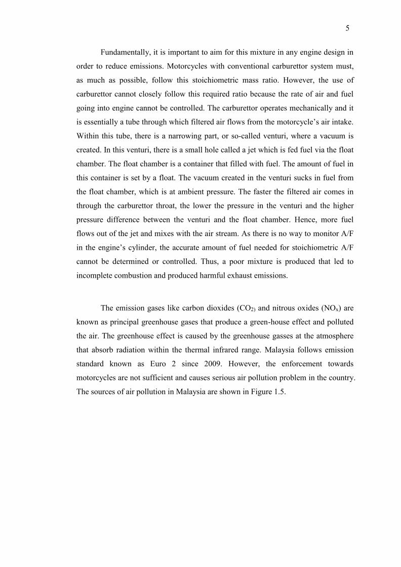
Fundamentally, it is important to aim for this mixture in any engine design in
order to reduce emissions. Motorcycles with conventional carburettor system must,
as much as possible, follow this stoichiometric mass ratio. However, the use of
carburettor cannot closely follow this required ratio because the rate of air and fuel
going into engine cannot be controlled. The carburettor operates mechanically and it
is essentially a tube through which filtered air flows from the motorcycle’s air intake.
Within this tube, there is a narrowing part, or so-called venturi, where a vacuum is
created. In this venturi, there is a small hole called a jet which is fed fuel via the float
chamber. The float chamber is a container that filled with fuel. The amount of fuel in
this container is set by a float. The vacuum created in the venturi sucks in fuel from
the float chamber, which is at ambient pressure. The faster the filtered air comes in
through the carburettor throat, the lower the pressure in the venturi and the higher
pressure difference between the venturi and the float chamber. Hence, more fuel
flows out of the jet and mixes with the air stream. As there is no way to monitor A/F
in the engine’s cylinder, the accurate amount of fuel needed for stoichiometric A/F
cannot be determined or controlled. Thus, a poor mixture is produced that led to
incomplete combustion and produced harmful exhaust emissions.
The emission gases like carbon dioxides (CO2) and nitrous oxides (NOx) are
known as principal greenhouse gases that produce a green-house effect and polluted
the air. The greenhouse effect is caused by the greenhouse gasses at the atmosphere
that absorb radiation within the thermal infrared range. Malaysia follows emission
standard known as Euro 2 since 2009. However, the enforcement towards
motorcycles are not sufficient and causes serious air pollution problem in the country.
The sources of air pollution in Malaysia are shown in Figure 1.5.

6
Figure 1.5: Sources of air pollution in Malaysia [6].
The pie chart above clearly indicates that the emission from transportations is
the biggest contributor to air pollution (60%). Other sources contributing to air
pollution were industrial emission, 19%; bush fires, 13%; air conditioning, 6% and
open burning at waste disposal sites, 3%. From the 60% sources of air pollution by
motor vehicle, the motorcycle contributes a large part in it compared with other types
of vehicle. Therefore, in recent years, an embedded electronic fuel injection system
in modern technology, which replaces the conventional carburettor system in the new
motorcycle models, has helped reduced the level of pollution.
As for year 2005 and above, most of the high capacity motorcycles have used
electronic fuel injection system (EFI) which is more efficient and reliable. The main
function of fuel injection system (FIS) is for metering the fuel. Fuel metering is the
process of determining the necessary amount of fuel and its delivery into the engine.
By using FIS, effective combustion can be achieved and nearly meet the required
A/F ratio. Thus, cleaner exhaust emissions are achieved and thus reduce the pollution
to the environment.
60%
19%
13%
6% 3%
Motor Vehicle
Industries
Bush Fires
Air Conditioning
Waste Disposal

7
1.2 Problem Statement
As discussed earlier, most of the small-engine vehicles used in developing
and poor countries are of the carburettor type that are very low in efficiency and
produce high level of hazardous emissions. The cost of FIS-type engine are, however,
very high. Therefore, the development of a low-cost FIS for small motorcycle engine
is important as it will provide a means for even the low-income users to share the
advantages of FIS and care for the environment at the same time.
One way to achieve this is by accurately estimating the engine load by using
the in-cylinder air mass flow rate (AMF) of the engine. Most of the control schemes
in modern FIS either approximated the AMF near the throttle plate using mass air
flow (MAF) sensor or in the intake manifold using manifold absolute pressure
(MAP) sensor. AMF estimation with the aids of MAF sensor can be reliable but
usually end up in high FIS cost due to design complexity. This is opposite to the one
that uses MAP sensor, which is much cheaper and simpler FIS but less accurate in
the AMF estimation. However, both approaches involve some physical parameter
calculations, which use lots of look-up tables and polynomial expressions. System
failure can happen if either of these sensors malfunction in some way. Even though
there is an advance FIS that utilizes both of these sensors, this lead to higher
production cost and more complex system.
Thus, the need of a method to estimate the AMF without using either sensors
is important as it will certainly reduce the cost of the system. With this method, the
system process can be made much simpler, which do not involves computations like
look-up tables and polynomial expressions. An accurate engine load estimation is
important as it will affect the performance of the engine. With an accurate load
estimation, an accurate amount fuel to be delivered to the engine can be obtained for
optimum engine performance.

8
1.3 Objective of the Study
This study embarks on the following objectives:
i. To develop a neural network model as an estimator to estimate a small
engine load by estimating the air mass flow rate in intake manifold so
that lower production cost of the system can be achieved by
eliminating the usage of sensors.
ii. To identify and develop a suitable training algorithm to train the
estimator in order to achieve an optimum performance.
iii. To ascertain the efficiency of the developed estimator by
incorporating a simple controller in the control system to control air to
fuel ratio of the engine.
1.4 Limitation and Scope of the Study
All the works in this study are focusing on the limitations and scopes below:
i. The engine load or the air mass flow rate (AMF) in the cylinder of the
engine is assumed to be the same as in the intake manifold so that a
speed-density approach can be used for control system.
ii. Neural network estimator model is focused on a single cylinder
motorcycle petrol engine with 4-strokes configuration.
iii. An electronic fuel injection system is used as the fuelling system of
the engine.
iv. MATLAB software is used for analysis in simulation and
experimental works.
v. A Mainline Dynolog Dynamometer test bench and system are used for
experimental data collection.

9
1.5 Contribution of the Research
This study leads to some contributions as follows:
i. An engine load estimator that can lead to low-cost FIS.
ii. A reliable hybrid training algorithm for neural network model that has
been proved its generalization and mapping capability as an estimator.
iii. Verification on the effectiveness of the above approach via simulation
and experimental validation.
1.6 Outline of the Thesis
This thesis consists of five chapters. Chapter 1 is the introduction which
summarize the purpose of the study. Chapter 2 is the literature review which contains
an explanation of the single cylinder motorcycle engine, fuel delivery system and a
review of the works done by past researchers on fuel injection control, engine load
estimation and training algorithms for neural network. Chapter 3 explains the
methodology developed for engine load estimation in this study. Chapter 4 contains
results and discussion and chapter 5 is conclusion followed by contribution of the
research and recommendations for future works.

129
REFERENCES
1. World Health Organization. WHO global status report on road safety 2013:
supporting a decade of action. World Health Organization. 2013
2. Nur Bazla, et al. Estimation of Dispersion of Carbon CO, NO2, and CO2
from port Klang - KLIA Road: Preliminary Findings. Transportation
Research Forum and Conferences (MUTRFC). 2010
3. Road Transport Deparment of Malaysia. http://www.jpj.gov.my/.
4. A. K, I. S., et al. Mode Choice Model for Vulnerable Motorcyclists in
Malaysia. Traffic Injury Prevention, 2006. 7(2): 150-154.
5. Heywood, J. B. Internal Combustion Engine Fundamentals. New York:
McGraw-Hill. 1988
6. The Malaysian Air Pollution Index Handbook. Sources of Air Pollution in
Malaysia. Malaysian Air Pollution Index Handbook. 2011.
7. Kolewe, B. et al. Gaussian Mixture Regression and Local Linear Network
Model for Data-driven Estimation of Air Mass. Control Theory &
Applications, 2015. 9(7): 1083-1092.
8. Fu-Shin, L. et al. Fuel Injection Motorcycle Engine Model Development.
IEEE International Conference on Networking, Sensing and Control. 2004.
Vol. 2. 1259-1264.
9. Pulkrabek, W. W. Engineering Fundamentals of the Internal Combustion
Engine. Vol. 478. Upper Saddle River, NJ.: Prentice Hall. 1997
10. Li, H. et al. The Lean Mixture Operational Limits of a SI Engine When
Operated on Fuel Mixtures. Internal Combustion Engine Division Fall
Technical Conference (ASME). 2005. 145-152.
11. Thornhill, E. Maintenance and Repair of Spraying Eequipment. International
Journal of Pest Management, 1984. 30: 266-281.
12. Roth, A. C. et al. Small Gas engines. 11th. ed. The Goodheart-Willcox
Company, Inc. 2012.

130
13. Heywood, J. B. and E. Sher. The Two-stroke Cycle Engine. Warrendale, PA:
Society of Automotive Engineers. 1999.
14. Heisler, H. Vehicle and Engine Technology. 2009.
15. Haworth, N. Powered Two wheelers in a Changing World - Challenges and
Opportunities. Accident Analysis & Prevention, 2012. 44(1): 12-18.
16. Li, L.P., et al. Improper Motorcycle Helmet Use in Provincial Areas of a
Developing Country. Accident Analysis & Prevention, 2008. 40(6): 1937-
1942.
17. Hayakawa, K., et al. 125cc Small Engine Fuel Injection System with Low
Emissions Solutions. SAE Technical Paper 0148-7191. 2004
18. Iyer, N. V. et al. Technical Assessment of Emission and Fuel Consumption
Reduction Potential from Two and Three Wheelers in India. SAE Technical
Paper. 2013.
19. Lorenz, N., Bauer, T. and Willson, B. Design of Direct Injection Retrofit Kit
for Small Two-Stroke Engines. JSAE Paper 20056601. 2005.
20. Jackson, S. et al. Development of a Fuelling System to Reduce Cold-start
Hydrocarbon Emissions in an SI Engine. SAE Technical Paper. 1996.
21. Taylor, C. F. The Internal-combustion Engine in Theory and Practice. Vol. 2.
Combustion, Fuels, Materials, Design: MIT press. 1985
22. Nakamura, M., Sawada, Y. and Hashimoto, S. Fuel Injection System for
Small Motorcycles. Japan: Yamaha Motor Technical Review. 2003
23. Nyberg, M. et al. Model Based Diagnosis of Leaks in the Air Intake System
of an SI-engine. SAE Technical Paper. 1998.
24. Nagai, Y., et al. Improving the Fuel Consumption of Small Motorcycle
Engine with YMJET-FI. SAE Technical Paper 2009-32-0049. 2009
25. Khan, M. A. et al. SI Engine Lean-Limit Extension Through LPG Throttle-
Body Injection for Low CO2 and NOx. SAE Technical Paper 2006-01-0495.
2006.
26. Dernotte, J. et al. Evaluation of Butanol–gasoline Blends in a Port Fuel-
injection, Spark-ignition Engine. Oil & Gas Science and Technology, 2010.
65(2): 345-351.
27. Harada, J. et al. Development of direct injection gasoline engine. SAE
Technical Paper. 1997.

131
28. Teoh, Y. H. and Gitano-Briggs, H. Two-stroke engine emission predictions
for premixed and directly injected gaseous fuels. USM Conference on
Product Development. 2007.
29. Latey, A. A. et al. Gasoline Fuel Injection Investigations on Single Cylinder
SI Engine. SAE Technical Paper. 2005.
30. Wei, L. et al. Study on Improvement of Fuel Economy and Reduction in
Emissions for Stoichiometric Gasoline Engines. Applied Thermal
Engineering, 2007. 27(17): 2919-2923.
31. He, B. Q. et al. A Study on Emission Characteristics of an EFI Engine with
Ethanol Blended Gasoline Fuels. Atmospheric Environment, 2003. 37(7):
949-957.
32. Postma, M. and Nagamune, R. Air-Fuel Ratio Control of Spark Ignition
Engines Using a Switching LPV Controller. IEEE Transactions on Control
Systems Technology, 2012. 20(5): 1175-1187.
33. Vojtisek-Lom, M. and Cobb, J. Vehicle Mass Emissions Measurement Using
a Portable 5-Gas Exhaust Analyzer and Engine Computer Data. Proceedings
of the 1997 Emission Inventory, Planning for the Future. 1997.
34. Stotsky, A. and Kolmanovsky, I. Application of Input Estimation Techniques
to Charge Estimation and Control in Automotive Engines. Control
Engineering Practice, 2002. 10(12): 1371-1383.
35. Sazhin, O. Novel Mass Air Flow Meter for Automobile Industry Based on
Thermal Flow Microsensor. II. Flow Meter, Test Procedures and Results.
Flow Measurement and Instrumentation, 2014. 35: 48-54.
36. Van Breemen, A. and De Vries, T. An Agent-based Framework for Designing
Multi-Controller Systems. Proceedings of the Fifth International Conference
on The Practical Applications of Intelligent Agents and Multi-Agent
Technology. 2000. 219-235.
37. Kamaruddin, T. N. A. T. and Darus, I. Z. M. PID Controller for Idle Speed
Control. 15th International Conference on Computer Modelling and
Simulation (UKSim). 2013. 247-253.
38. Powell, J. D., Fekete, N. and Chang, C. F. Observer-based Air Fuel Ratio
Control. Control Systems, IEEE, 1998. 18(5): 72-83.

132
39. Wang, S. and Yu. D. L. An Application of Second-Order Sliding Mode
Control for IC Engine Fuel Injection. Canadian Conference on Electrical and
Computer Engineering (CCECE '06). 2006. 1035-1038.
40. Ahmed, Q. and Bhatti, A. I. Estimating SI Engine Efficiencies and
Parameters in Second-Order Sliding Modes. IEEE Transactions on Industrial
Electronics, 2011. 58(10): 4837-4846.
41. Pace, S. and Zhu, G. G. Air-to-Fuel and Dual-Fuel Ratio Control of an
Internal Combustion Engine. SAE Technical Paper 2009-01-2749. 2009
42. Ahmed, Q. and Bhatti, A. I. Second Order Sliding Mode Observer for
Estimation of SI Engine Volumetric Efficiency & Amp; Throttle Discharge
Coefficient. 11th International Workshop on Variable Structure Systems
(VSS). 2010. 307-312.
43. Wang, S. and Yu, D. A New Development of Internal Combustion Engine
Air-Fuel Ratio Control with Second-Order Sliding Mode. Journal of Dynamic
Systems, Measurement, and Control, 2007. 129(6): 757-766.
44. Xiaohong, J. and Tielong, S. Lyapunov-design of Adaptive Air-Fuel Ratio
Control for Gasoline Engines Based on Mean-Value Model. IEEE 30th
Chinese Control Conference (CCC). 2011. 6146-6150.
45. Shi, Y., et al. Air–fuel Ratio Prediction and NMPC for SI engines with
Modified Volterra Model and RBF network. Engineering Applications of
Artificial Intelligence, 2015. 45: 313-324.
46. Wang, S. W. and Yu, D. L. Adaptive air-fuel ratio control with MLP network.
International Journal of Automation and Computing, 2005. 2(2): 125-133.
47. Vance, J. B., et al. Neural Network Controller Development and
Implementation for Spark Ignition Engines with High EGR Levels. IEEE
Transactions on Neural Networks, 2007. 18(4): 1083-1100.
48. Li, G. and Yan, F. NN-based Fuel Injection Control System for Hybrid Fuel
Engine. IEEE Symposium on Electrical & Electronics Engineering
(EEESYM). 2012. 336-340.
49. Manzie, C., M. Palaniswami, and Watson, H. A Novel Approach to Fuel
Injection Control Using a Radial Basis Function Network. IEEE International
Joint Conference on Neural Networks Proceedings 1998. IEEE World
Congress on Computational Intelligence. 1998. Vol. 2. 986-991.

133
50. Luo, S., Gong, Y. and Wu, C. Research of Neural Network Control on
Ignition Spark Angle of Vehicle Electronic-Control Gasoline Engine. Third
International Conference on Measuring Technology and Mechatronics
Automation (ICMTMA). 2011. 1081-1083.
51. Sardarmehni, T., et al. Robust Neural Predictive Control of Normalized Air-
to-Fuel Ratio in Internal Combustion Engines. 13th Iranian Conference on
Fuzzy Systems (IFSC). 2013. 1-4.
52. Niu, B., et al. A Multi-swarm Optimizer Based Fuzzy Modeling Approach
Ffor Dynamic Systems Processing. Neurocomputing, 2008. 71(7): 1436-1448.
53. Tasdemir, S., et al. Artificial Neural Network and Fuzzy Expert System
Comparison for Prediction of Performance and Emission Parameters on a
Gasoline Engine. Expert Systems with Applications, 2011. 38(11): 13912-
13923.
54. Jansri, A. and Sooraksa, P. Enhanced Model and Fuzzy Strategy of Air to
Fuel Ratio Control for Spark Ignition Engines. Computers & Mathematics
with Applications, 2012. 64(5): 922-933.
55. Mohamed, H. M., et al. Fuzzy Modeling and Control af a Spark Ignition
Engine Idle Mode. Proceedings of the 2000 TENCON. 2000. Vol. 2. 586-591
56. Saraswati, S., Agarwal, P. K. and Chand, S. Neural Networks and Fuzzy
Logic-Based Spark Advance Control of SI Engines. Expert Systems with
Applications, 2011. 38(6): 6916-6925.
57. Jian-Xin, X. and Zhong-Sheng, H. Notes on Data-driven system Approaches.
Acta Automatica Sinica, 2009. 35(6): 668-675.
58. Lespinats, S., et al. DD-HDS: A Method for Visualization and Exploration of
High-Dimensional Data. IEEE Transactions on Neural Networks, 2007.
18(5): 1265-1279.
59. Gerasimov, D.N., . Javaherian, H. and Nikiforov, V.O. Data Driven Inverse-
Model Control of SI Engines. American Control Conference (ACC). 2011.
426-431.
60. Lu, X., et al. Design of a Data-Driven Predictive Controller for Start-up
Process of AMT Vehicles. IEEE Transactions on Neural Networks, 2011.
22(12): 2201-2212.

134
61. Yunfeng, H., et al. Data-driven Model Predictive Control of Air-fuel Ratio for
PFISI Engine. 11th World Congress on in Intelligent Control and Automation
(WCICA). 2014. 4577-4582.
62. Kerkeni, H., Lauber, J. and Guerra, T. M. Estimation of Individual In-
Cynlinder Air Mass Flow Via Periodic Observer in Takagi-Sugeno Form.
IEEE Vehicle Power and Propulsion Conference (VPPC). 2010. 1-6.
63. Xu, K. J. et al. Improvements of Nonlinear Dynamic Modeling of Hot-film
MAF Sensor. Sensors and Actuators A: Physical, 2008. 147(1): 34-40.
64. De Nicolao, G. et al. Modelling the Volumetric Efficiency of IC Engines:
Parametric, Non-parametric and Neural Techniques. Control Engineering
Practice, 1996. 4(10):1405-1415.
65. Zhang, F. et al. Linear Parameter-varying Lean Burn Air-fuel Ratio Control
for a Spark Ignition Engine. Journal of Dynamic Systems, Measurement, and
Control, 2007. 129(4): 404-414.
66. Leroy, T. et al. Modeling Fresh Air Charge and Residual Gas Fraction on a
Dual Independent Variable Valve Timing SI Engine. SAE International
Journal of Engines, 2008. 1: 627-635.
67. Bandel, W. et al. The Turbocharged GDI Engine: Boosted Synergies for High
Fuel Economy Plus Ultra-low Emission. SAE Technical Paper. 2006.
68. Jahirul, M. I. et al. Comparative engine performance and emission analysis of
CNG and gasoline in a retrofitted car engine. Applied Thermal Engineering,
2010. 30(14): 2219-2226.
69. Tanabe, H. et al. Fuel Behavior Model-based Injection Control for
Motorcycle Port-injection Gasoline Engines. SAE Technical Paper. 2007.
70. Senatore, A. et al. Fluid-dynamic Analysis of Motorbike Race Engine
Injection System. International Mechanical Engineering Congress and
Exposition (ASME). 2008. 277-283.
71. Dase, C. et al. Motorcycle Control Prototyping Using an FPGA-based
Embedded Control System. IEEE Control Systems, 2006. 26(5): 17-21.
72. Turin, R., Dagci, O. and Chang, M. F. Low-Cost Air Estimation. SAE Int. J.
Engines, 2009. 2(1): 357-369.
73. Battistoni, M. et al. Experimental Investigation of a Port Fuel Injected Spark
Ignition Engine Fuelled with Variable Mixtures of Hydrogen and Methane.
SAE Technical Paper. 2013.

135
74. Kar, K. et al. Measurement of Vapor Pressures and Enthalpies of
Vaporization of Gasoline and Ethanol Blends and Their Effects on Mixture
Preparation in an SI Engine. SAE International Journal of Fuels and
Lubricants, 2008. 1: 132-144.
75. Muske, K. R. et al. Adaptive Analytical Model-based Control for SI Engine
Air–fuel ratio. IEEE Transactions on Control Systems Technology, 2008.
16(4): 763-768.
76. Guzzella L. and Onder C. Introduction to Modeling and Control of Internal
Combustion Engine Systems. Springer Science & Business Media. 2009.
77. Lansky, L. Diesel Engine Modelling and Control. Master Thesis. Czech
Technical University; 2008.
78. Kalman, R. E. Contributions to the Theory of Optimal Control. Bol. Soc. Mat.
Mexicana, 1960. 5(2): 102-119.
79. Kalman, R. E. A New Approach to Linear Filtering and Prediction Problems.
Journal of Fluids Engineering, 1960. 82(1): 35-45.
80. Kalman, R. E. and Bucy, R. S. New Results in Linear Filtering and Prediction
Theory. Journal of Fluids Engineering, 1961. 83(1): 95-108.
81. Barbarisi, O., Alessandro, G. and Luigi, G. An Extended Kalman Observer
for the In-Cylinder Air Mass Flow Estimation. Proceedings of MECA02
International Workshop on Diagnostics in Automotive Engines and Vehicles,
Oct., 2002. Fisciano SA. 2002. 1-14.
82. Dawei, Q., et al. LPG Engine Inlet Manifold Pressure Measurement Based on
State Prediction. Asia-Pacific Power and Energy Engineering Conference
(APPEEC). 2011. 1-4.
83. Wu, J. D. et al. Fault Diagnosis for Internal Combustion Engines Using
Intake Manifold Pressure and Artificial Neural Network. Expert Systems with
Applications, 2010. 37(2): 949-958.
84. Chen, B. C., Wu, Y. Y. and Tsai, H. C. Estimation of Intake Manifold
Absolute Pressure Using Kalman Filter. SAE Technical Paper 2013-32-9061.
2013.
85. Worm, J. An Evaluation of Several Methods for Calculating Transient
Trapped Air Mass with Emphasis on the “delta p” Approach. SAE Technical
Paper 0148-7191. 2005.

136
86. Ivansson, N. Estimation of the Residual Gas Fraction in an HCCI-engine
using Cylinder Pressure. Undergraduate Thesis. Linkoping University. 2003.
87. Andersson, I. Cylinder Pressure and Ionization Current Modeling for Spark
Ignited Engines. Linkopings Universitet, SE, 2002. 581: 83.
88. Eriksson, L. and Andersson, I. An Analytic Model for Cylinder Pressure in a
Four Stroke SI Engine. SAE Technical Paper. 2002
89. Hart, M., Ziegler, M. and Loffeld, O. Adaptive Estimation of Cylinder Air
Mass Using the Combustion Pressure. SAE Technical Paper 980791. 1998
90. Maybeck, P.S. Stochastic Models, Estimation, and Control. Vol. 3: Academic
press. 1982
91. Mehra, R. Approaches to Adaptive Filtering. IEEE Symposium on Adaptive
Processes (9th) Decision and Control. 1970. 141.
92. Mladek, M. Cylinder Pressure for Control Purposes of Spark Ignition Engines.
Ph.D. Thesis, Swiss Federal Institute of Technology. 2003
93. Ponti, F., Pianai, J. and Suglia. R. Residual Gas Model for On-line Estimation
for Inlet and Exhaust Continous VVT Engine Configuration. IFAC world
congress. 2004
94. Mladek, M. and Onder, C. H. A Model for the Estimation of Inducted Air
Mass and the Residual Gas Fraction Using Cylinder Pressure Measurements.
SAE Technical Paper 0148-7191. 2000.
95. Akimoto, A., Itoh, H. and Suzuki, H. Development of Delta P Method to
Optimize Transient A/F-Behavior in MPI Engine. JSAE Review, 1989. 10(4).
96. Worm, J. An Evaluation of Several Methods for Calculating Transient
Trapped Air Mass with Emphasis on the “Delta P” Approach. SAE Technical
Paper 0148-7191. 2005.
97. Colin, G., et al. In-cylinder Mass Estimation using Cylinder Pressure. SAE
Technical Paper 0148-7191. 2007.
98. Desantes, J.M., et al. Air Mass Flow Estimation in Turbocharged Diesel
Engines from In-cylinder Pressure Measurement. Experimental Thermal and
Fluid Science, 2010. 34(1): 37-47.
99. Liu, J., et al. Development of a Fast Response High Accuracy Virtual Air
Flow Meter for Internal Combustion Engine Applications. Third International
Conference on Measuring Technology and Mechatronics Automation
(ICMTMA). 2011. 1037-1041.

137
100. Weeks, R. W. and Moskwa, J. J. Transient Air Flow Rate Estimation in a
Natural Gas Engine Using a Nonlinear Observer. SAE Technical Paper
940759. 1994.
101. Andersson, P. and Eriksson, L. Air-to-Cylinder Observer on a Turbocharged
SI-Engine with Wastegate. SAE Technical Paper 2001-01-0262. 2001.
102. Leroy, T., et al. Air Path Estimation for a Turbocharged SI Engine with
Variable Valve Timing. American Control Conference (ACC '07). 2007.
5088-5093.
103. Kerkeni, H., Lauber, J. and Guerra, T. M. Estimation of Individual In-
Cynlinder Air Mass Flow Via Periodic Observer in Takagi-Sugeno Form.
IEEE Vehicle Power and Propulsion Conference (VPPC). 2010. 1-6.
104. Hendricks, E. and Sorenson , S. Mean Value SI Engine Model for Control
Studies. American Control Conference. 1990. 1882-1887.
105. Turin, R., Dagci, O. and Chang, M. F. Low-Cost Air Estimation. SAE Int. J.
Engines, 2009. 2(1): 357-369.
106. Polóni, T., Rohaľ-Ilkiv, B., and Arne Johansen, T. Mass Flow Estimation
with Model Bias Correction for a Turbocharged Diesel Engine. Control
Engineering Practice, 2014. 23: 22-31.
107. Sawomir, W., et al. In-cylinder Mass Flow Estimation and Manifold Pressure
Dynamics for State Prediction in Si Engines. Acta Polytechnica, 2014. 54(3):
240-247.
108. Chevalier, A M. R., Vigild, C. W. and Hendricks, E. Predicting the Port Air
Mass Flow of SI Engines in Air/Fuel Ratio Control Applications. SAE Special
Publications. SP-1500. 2000. 1.
109. Mehrotra, K., Mohan, C. K. and Ranka, S. Elements of Artificial Neural
Networks. Cambridge, Massachusetts: the MIT Press. 1997
110. Taglialatela, F., Cesario, N. and Lavorgna, M. Soft Computing Mass Air
Flow Estimator for a Single-Cylinder SI Engine. SAE Technical Paper 2006-
01-0010. 2006
111. Wu, B., et al. Using Artificial Neural Networks for Representing the Air Flow
Rate through a 2.4 Liter VVT Engine. SAE Technical Paper 2004-01-3054.
2004

138
112. Wahba, G. and Craven, P. Smoothing Noisy Data with Spline Functions.
Estimating the Correct Degree of Smoothing by the Method of Generalized
Cross-Validation. Numerische Mathematik, 1978. 31: 377-404.
113. Fine, T. L. Feedforward neural network methodology. Springer Science &
Business Media. 2006.
114. Aizenberg, I. and Moraga, C. Multilayer Feedforward Neural Network Based
on Multi-Valued Neurons (MLMVN) and a Backpropagation Learning
Algorithm. Soft Computing, 2007. 11(2): 169-183.
115. Levenberg, K. A Method for The Solution of Certain Problems in Least
Squares. Quart. Applied Math, 1944. 2: 164-168.
116. Marquardt, D. W. An Algorithm for Least-Squares Estimation of Nonlinear
Parameters. Journal of the Society for Industrial and Applied Mathematics,
1963. 11(2): 431-441.
117. Rumelhart, D. E., Hinton, G. E. and Williams, R.J. Learning Representations
by Back-propagating Errors. Nature, 1986: 323,533-538.
118. Werbos, P. J. Backpropagation: Past and Future. IEEE International
Conference on Neural Networks. 1988. Vol. 1. 343-353
119. Osborne, M.R. Fisher's Method of Scoring. International Statistical Review,
1992: 99-117.
120. Glorot, X. and Bengio, Y. Understanding the Difficulty of Training Deep
Feedforward Neural Networks. International conference on artificial
intelligence and statistics. 2010. 249-256.
121. MacKay, D .J .C. A Practical Bayesian Framework for Backpropagation
Networks. Neural Comput, 1992. 4(3): 448-472.
122. Haykin, S. S. Neural Networks and Learning Machines. Vol. 3. Pearson
Education Upper Saddle River. 2009.
123. Chen H. and Yao, X. Regularized Negative Correlation Learning for Neural
Network Ensembles. IEEE Transactions on Neural Networks, 2009. 20(12):
1962-1979.
124. Fadare, D. and Ofidhe, U. Artificial Neural Network Model for Prediction of
Friction Factor in Pipe Flow. Journal of Applied Sciences Research, 2009.
5(6): 662-670.
125. Poland, J. On the Robustness of Update Strategies for the Bayesian
Hyperparameter. Training, 2001. 10: 2.

139
126. Suratgar, A. A. et al. Modified Levenberg-Marquardt Method for Neural
Networks Training. World Acad Sci Eng Technol, 2005. 6: 46-48.
127. Hornik, K. Approximation Capabilities of Multilayer Feedforward Networks.
Neural Networks, 1991. 4(2): 251-257.
128. Huang, G. B. et al. Extreme Learning Machine: A New Learning Scheme Of
Feedforward Neural Networks. Proceedings of IEEE International Joint
Conference On Neural Networks. 2004. 985-990.
129. Wilamowski, B. M. and Yu, H. Improved computation for Levenberg–
Marquardt Training. IEEE Transactions on Neural Networks, 2010. 21(6):
930-937.
130. Kennedy, J. et al. Swarm intelligence. San Francisco: Morgan Kaufmann
Publishers. 2001
131. Shi, X. et al. An Improved GA and a Novel PSO-GA-based Hybrid
Algorithm. Information Processing Letters, 2005. 93(5): 255-261.
132. Beasley, J. E. and Chu, P. C. A Genetic Algorithm for the Set Covering
Problem. European Journal of Operational Research, 1996. 94(2): 392-404.
133. Houck, C. R. et al. A Genetic Algorithm for Function Optimization: A Matlab
Implementation. NCSU-IE TR. Vol. 95. 1995.
134. Arifovic, J. Genetic algorithm learning and the cobweb model. Journal of
Economic dynamics and Control, 1994. 18(1): 3-28.
135. Liu, B. et al. An Effective PSO-based Memetic Algorithm for Flow Shop
Scheduling. IEEE Transactions on Systems, Man, and Cybernetics, Part B:
Cybernetics, 2007. 37(1): 18-27.
136. Chau, K. Application of a PSO-based Neural Network in Analysis of
Outcomes of Construction Claims. Automation in Construction, 2007. 16(5):
642-646.
137. MATLAB and Modeling a Fault-Tolerant Fuel Control System Released
2013a, The MathWorks, Inc., Natick, Massachusetts, United States.
138. Hushim, M. F. et al. PFI System for Retrofitting Small 4-Stroke Gasoline
Engines. International Journal of Environmental Science and Development,
2013. 4(4): 375-378.
139. Fontana, G. and Galloni, E. Variable Valve Timing for Fuel Economy
Improvement in a Small Spark-ignition Engine. Applied Energy, 2009. 86(1):
96-105.

140
140. Medeiros, M. C. et al. Building Neural Network Models for Time Series: A
Statistical Approach. Journal of Forecasting, 2006. 25(1): 49-75.
141. Kennedy, J. The Particle Swarm: Social Adaptation of Knowledge.
Proceedings of the IEEE International Conference on Evolutionary
Computation. 1997. 303-308.
142. Shi, Y. and Eberhart, R.C. A Modified Particle Swarm Optimizer.
Proceedings of the IEEE Congress on Evolutionary Computation. 1998. 69-
73.
143. Shi, Y. and Eberhart, R.C. Parameter Selection in Particle Swarm
Optimization. Proceedings of the Seventh Annual Conference on
Evolutionary Programming. 1998. 591-600.
144. Shi, Y. and Eberhart, R. C. Empirical Study of Particle Swarm Optimization.
Proceedings of the IEEE Congress on Evolutionary Computation. 1999.
1945-1950.
145. Carlisle, A. and Dozier, G. An Off-the-self PSO. Proceedings of the
Workshop on Particle Swarm Optimization. 2001.
146. Beielstein, T., Parsopoulos, K.E. and Vrahatis, M.N. Tuning PSO Parameters
Through Sensitivity Analysis. Technical Report. Reihe Computational
Intelligence CI 124/02, Department of Computer Science, University of
Dortmund. 2002.
147. Naka, S., Genji, T., Yura, T. and Fukuyama, Y. A Hybrid Particle Swarm
Optimization for Distribution State Estimation. IEEE Transactions on Power
Systems, 2003. 18 (1): 60-68.
148. Eberhart, R.C. and Shi, Y. Comparing Inertia Weights and Constriction
Factors in Particle Swarm Optimization. Proceedings of the IEEE Congress
on Evolutionary Computation. 2000. 84-88.
149. Suganthan, P.N. Particle Swarm Optimiser with Neighborhood Operator.
Proceedings of the IEEE Congress on Evolutionary Computation, 1999.
1958-1962.
150. Yoshida, H., Fukuyama, Y., Takayama, Y. and Nakanishi. A Particle Swarm
Optimization for Reactive Power and Voltage Control in Electric Power
Systems Considering Voltage Security Assessment. Proceedings of the IEEE
International Conference on Systems, Man, and Cybernetics. 1999. 502.

141
151. Shi, Y. and Eberhart, R.C. Fuzzy Adaptive Particle Swarm Optimization.
Proceedings of the IEEE Congress on Evolutionary Computation. 2001.
152. Naka, S., Genji, T., Yura, T. and Fukuyama, Y. Practical Distribution State
Estimation Using Hybrid Particle Swarm Optimization. IEEE Power
Engineering Society Winter Meeting. 2001. 815–820.