"Small Deviations and Big Failures in Vibration and Noise ...sandv.com/downloads/1012davi.pdf ·...
4
www.SandV.com 14 SOUND & VIBRATION/DECEMBER 2010 The difference between design intent and actual implementation is frequently a problem in real construction. For vibration and noise isolation hardware, seemingly innocuous deviations can result in major deficiencies in performance. From hardware selec- tion to installation and adjustment, vibration isolation systems present significant challenges. In this article, we offer insight into a broad spectrum of problematic rotating mechanical systems. Numerous categories of vibration-isolation failure are identified, and detailed photographs highlight subtle errors in isolator selec- tion, installation, and adjustment that can lead to poor vibration and noise performance. A spectacular example of comprehensive facility-wide failure is given, with ground vibration data from a brownfield infill site adjacent to an outdated textile factory. For many high-tech projects, floor vibration is a key parameter to successful manufacturing and research. Facility vibration con- tributes to product loss, poor yield, and low throughput. In this regime, tools and processes are sensitive to vibrations far below the threshold of human perception. 1 Vibration and acoustical design for these and other facilities requires attention to major rotating mechanical equipment supporting the building, such as fans, pumps, chillers, and others. While this presentation focuses on machine vibration isolation for highly sensitive nanotechnology laboratories and microelectronics manufacturing, the principles also apply to systems where human-perceptible vibration or noise is of concern. During design, vibration isolators are specified for those rotat- ing machines that could impart enough forces to create disturbing vibrations or sounds. After major construction is completed and base-building systems are in place, machines and vibration isola- tion systems must be inspected to ensure that the correct hardware was used and that the systems were implemented properly. Even in well-designed systems, problems with alignment, forgot- ten shims, and eccentric loading are all too frequent. Each type of failure diminishes (and sometimes even reverses) the attenuation that the vibration isolation system was intended to provide. Basic Isolator Theory and Selection Regardless of the regime of operation, isolators work by present- ing an impedance discontinuity across the support. By introduc- ing compliance into the connection, the transmission of applied forces is reduced at some frequencies at the expense of increasing transmission at other frequencies. While transmitted force is the key parameter – from the receiver’s perspective, motion at the isolated machine is uninteresting – the force transmissibility is numerically identical to the motion transmissibility. 2 A lightly damped single-degree-of-freedom (SDOF) mass-spring system is a reasonable model for well-isolated machinery. The primary goal of isolator selection and design is to appropriately match isolator properties to the anticipated forcing function of the isolated equipment. In particular, isolator selection is driven by achieving appropriate separation between the isolator natural frequency f n and the machine drive frequencies f i . For SDOF systems, the isolator fundamental frequency may be calculated from the ratio of the spring constant to the supported mass; 2 since gravity is a constant in terrestrial applications, this may be reduced to a simple expression based on the static deflec- tion d (in centimeters): The transmissibility of the system is the ratio of the imparted force F i to the transmitted force F t and is related only to ratios of fre- quency (f i /f n ) and damping, 2 with the damping ratio given by h: Manipulation of Equation 2 reveals that the isolator transmis- sibility t is less than unity (and therefore attenuating rather than amplifying) only when the ratio of drive frequency to natural frequency is greater than the square root of 2. If the imparted driv- ing frequency f i is sufficiently removed from the spring natural system f n and if the system is sufficiently lightly damped, then the transmissibility may be estimated as: Isolator efficiency may be defined as 1-t and is commonly ex- pressed as a percentage. While significant attention must be paid to other design parameters, Equations 1 through 3 provide enough background to understand the types of vibration isolation system failures highlighted in this paper. Isolator Failures Many failure modes exist for the isolation of rotating systems. Here, we discuss the three most basic failure modes: poor system design; inappropriate isolator selection; and fabrication/installa- tion failure. Small Deviations and Big Failures in Vibration and Noise Isolation (1) f k m n = = 1 2 5 p d Figure 1. Six examples of poor vibration isolation system design from a conceptual perspective. The concepts in a-d undermine the isolator by shorting. The concepts in e and f potentially introduce unintended dynam- ics via weight distribution. (2) t h h = = + Ê Ë Á ˆ ¯ ˜ - Ê Ë Á ˆ ¯ ˜ È Î Í Í ˘ ˚ ˙ ˙ + Ê Ë Á ˆ ¯ ˜ F F f f f f f f i t i n i n i n 1 2 1 2 2 2 2 2 (3) t ª Ê Ë Á ˆ ¯ ˜ - È Î Í Í ˘ ˚ ˙ ˙ - f f i n 2 1 1 J. Byron Davis and Ahmad Bayat, Vibro-Acoustic Consultants, San Francisco, California
Transcript of "Small Deviations and Big Failures in Vibration and Noise ...sandv.com/downloads/1012davi.pdf ·...

www.SandV.com14 SOUND & VIBRATION/DECEMBER 2010
The difference between design intent and actual implementation is frequently a problem in real construction. For vibration and noise isolation hardware, seemingly innocuous deviations can result in major deficiencies in performance. From hardware selec-tion to installation and adjustment, vibration isolation systems present significant challenges. In this article, we offer insight into a broad spectrum of problematic rotating mechanical systems. Numerous categories of vibration-isolation failure are identified, and detailed photographs highlight subtle errors in isolator selec-tion, installation, and adjustment that can lead to poor vibration and noise performance. A spectacular example of comprehensive facility-wide failure is given, with ground vibration data from a brownfield infill site adjacent to an outdated textile factory.
For many high-tech projects, floor vibration is a key parameter to successful manufacturing and research. Facility vibration con-tributes to product loss, poor yield, and low throughput. In this regime, tools and processes are sensitive to vibrations far below the threshold of human perception.1 Vibration and acoustical design for these and other facilities requires attention to major rotating mechanical equipment supporting the building, such as fans, pumps, chillers, and others. While this presentation focuses on machine vibration isolation for highly sensitive nanotechnology laboratories and microelectronics manufacturing, the principles also apply to systems where human-perceptible vibration or noise is of concern.
During design, vibration isolators are specified for those rotat-ing machines that could impart enough forces to create disturbing vibrations or sounds. After major construction is completed and base-building systems are in place, machines and vibration isola-tion systems must be inspected to ensure that the correct hardware was used and that the systems were implemented properly.
Even in well-designed systems, problems with alignment, forgot-ten shims, and eccentric loading are all too frequent. Each type of failure diminishes (and sometimes even reverses) the attenuation that the vibration isolation system was intended to provide.
Basic Isolator Theory and SelectionRegardless of the regime of operation, isolators work by present-
ing an impedance discontinuity across the support. By introduc-ing compliance into the connection, the transmission of applied forces is reduced at some frequencies at the expense of increasing transmission at other frequencies. While transmitted force is the key parameter – from the receiver’s perspective, motion at the isolated machine is uninteresting – the force transmissibility is numerically identical to the motion transmissibility.2
A lightly damped single-degree-of-freedom (SDOF) mass-spring system is a reasonable model for well-isolated machinery. The primary goal of isolator selection and design is to appropriately match isolator properties to the anticipated forcing function of the isolated equipment. In particular, isolator selection is driven by achieving appropriate separation between the isolator natural frequency fn and the machine drive frequencies fi.
For SDOF systems, the isolator fundamental frequency may be calculated from the ratio of the spring constant to the supported mass;2 since gravity is a constant in terrestrial applications, this may be reduced to a simple expression based on the static deflec-tion d (in centimeters):
The transmissibility of the system is the ratio of the imparted force Fi to the transmitted force Ft and is related only to ratios of fre-
quency (fi/fn) and damping,2 with the damping ratio given by h:
Manipulation of Equation 2 reveals that the isolator transmis-
sibility t is less than unity (and therefore attenuating rather than amplifying) only when the ratio of drive frequency to natural frequency is greater than the square root of 2. If the imparted driv-ing frequency fi is sufficiently removed from the spring natural system fn and if the system is sufficiently lightly damped, then the transmissibility may be estimated as:
Isolator efficiency may be defined as 1-t and is commonly ex-pressed as a percentage. While significant attention must be paid to other design parameters, Equations 1 through 3 provide enough background to understand the types of vibration isolation system failures highlighted in this paper.
Isolator FailuresMany failure modes exist for the isolation of rotating systems.
Here, we discuss the three most basic failure modes: poor system design; inappropriate isolator selection; and fabrication/installa-tion failure.
Small Deviations and Big Failures in Vibration and Noise Isolation
(1)fkmn = =1
25
p d
Figure 1. Six examples of poor vibration isolation system design from a conceptual perspective. The concepts in a-d undermine the isolator by shorting. The concepts in e and f potentially introduce unintended dynam-ics via weight distribution.
(2)th
h
= =+
ÊËÁ
ˆ¯̃
-ÊËÁ
ˆ¯̃
È
ÎÍÍ
˘
˚˙˙
+ÊËÁ
ˆ¯̃
FF
ff
ff
ff
i
t
i
n
i
n
i
n
1 2
1 2
2
22
2
(3)t ªÊËÁ
ˆ¯̃
-È
ÎÍÍ
˘
˚˙˙
-ff
i
n
2 1
1
J. Byron Davis and Ahmad Bayat, Vibro-Acoustic Consultants, San Francisco, California
www.SandV.com SOUND & VIBRATION/DECEMBER 2010 15
Poor Vibration Isolation System Design. The mathematical discussion above considers the isolated system as a simple SDOF mass-spring system. For spring or other compliant isolators to behave this way, certain criteria must be met. Some of these are beyond the scope of this discussion; however, the most basic is that the isolators must allow the system to freely float. In Figure 1, we present six photos of poorly performing systems. Each of these systems was compromised in the design stage.
In Figure 1a through 1d, the isolator is “shorted out,” meaning that not all of the load is supported by the isolators. The pump in 1a has attached piping that is directly supported on the floor; flexible connections are inserted after (in the topological sense) the connection to the floor. Similarly, some of the pipe framing for the pump in 1b is attached to the floating base of the pump. In 1c, a compressor is placed on a thick neoprene-style isolator; however, the isolator is circumvented, since the entire frame is bolted to the floor. A circuitous shorting condition is illustrated in Figure 1d, where a fan is given lateral support (not a true seismic snubber) via a neoprene-padded restraint. Close inspection reveals that the neoprene is strongly engaged by the framing.
In Figures 1e and 1f, awkward bases and weight distribution create the possibility of unintended dynamics. In 1e, the base is L-shaped and loaded eccentrically. No inertia base is present in 1f; due to the weight distribution, the center of gravity is unusu-ally high. Both of these installations are susceptible to damage in seismic events. Additionally, the possibility of significant excita-tion of the isolator fundamental and other unintended motions even during normal operation presents an inappropriate risk for exceedances or future misalignment/failure.
Inappropriate Vibration Isolator Selection. Isolator selection is based on the frequency content of the forcing function and the required level of isolation. As noted above, the degree of isolation improves with increased separation between the drive frequency and the isolator frequency. Equation 2 shows that the most ef-ficient isolator will have the lowest feasible natural frequency fn and the smallest damping ratio h. Since much of the damping in the system comes from items like attached piping and electrical connections – damping is rarely added deliberately to the system – isolator selection comes down to choosing a compliant element with enough static deflection to provide a suitably low natural
frequency by Equation 1. Aside from the primary task of selecting isolators based on achievable isolation frequencies, notions of maintainability and risk of failure are also important.
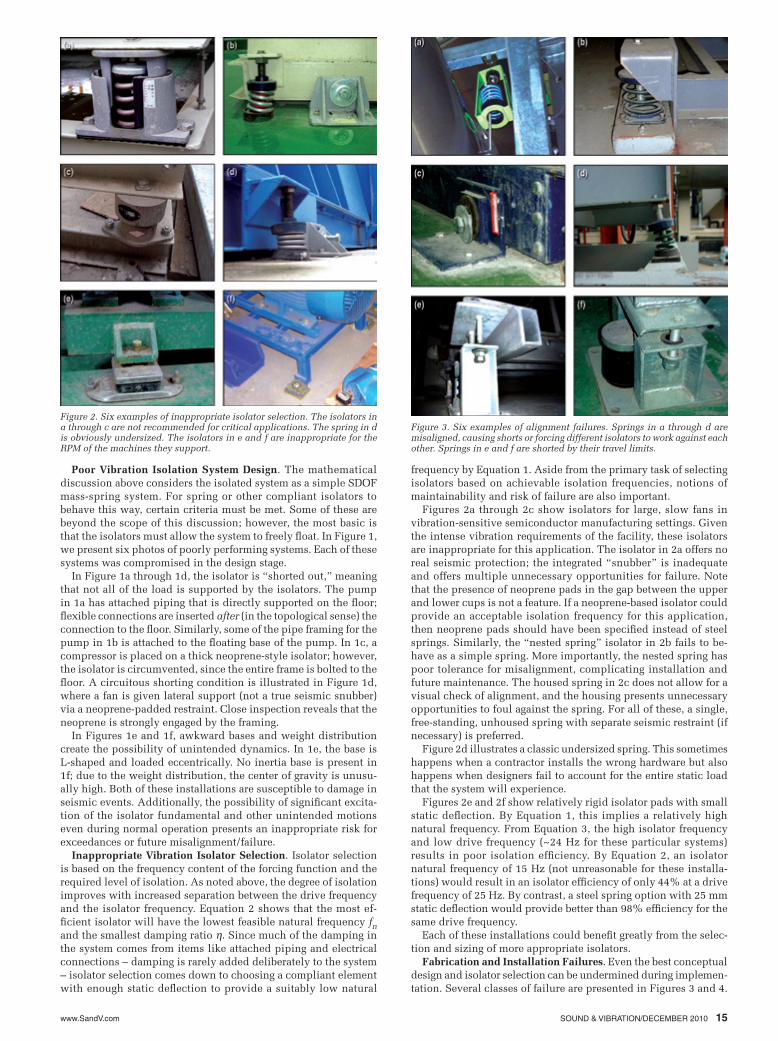
Figures 2a through 2c show isolators for large, slow fans in vibration-sensitive semiconductor manufacturing settings. Given the intense vibration requirements of the facility, these isolators are inappropriate for this application. The isolator in 2a offers no real seismic protection; the integrated “snubber” is inadequate and offers multiple unnecessary opportunities for failure. Note that the presence of neoprene pads in the gap between the upper and lower cups is not a feature. If a neoprene-based isolator could provide an acceptable isolation frequency for this application, then neoprene pads should have been specified instead of steel springs. Similarly, the “nested spring” isolator in 2b fails to be-have as a simple spring. More importantly, the nested spring has poor tolerance for misalignment, complicating installation and future maintenance. The housed spring in 2c does not allow for a visual check of alignment, and the housing presents unnecessary opportunities to foul against the spring. For all of these, a single, free-standing, unhoused spring with separate seismic restraint (if necessary) is preferred.
Figure 2d illustrates a classic undersized spring. This sometimes happens when a contractor installs the wrong hardware but also happens when designers fail to account for the entire static load that the system will experience.
Figures 2e and 2f show relatively rigid isolator pads with small static deflection. By Equation 1, this implies a relatively high natural frequency. From Equation 3, the high isolator frequency and low drive frequency (~24 Hz for these particular systems) results in poor isolation efficiency. By Equation 2, an isolator natural frequency of 15 Hz (not unreasonable for these installa-tions) would result in an isolator efficiency of only 44% at a drive frequency of 25 Hz. By contrast, a steel spring option with 25 mm static deflection would provide better than 98% efficiency for the same drive frequency.
Each of these installations could benefit greatly from the selec-tion and sizing of more appropriate isolators.
Fabrication and Installation Failures. Even the best conceptual design and isolator selection can be undermined during implemen-tation. Several classes of failure are presented in Figures 3 and 4.
Figure 2. Six examples of inappropriate isolator selection. The isolators in a through c are not recommended for critical applications. The spring in d is obviously undersized. The isolators in e and f are inappropriate for the RPM of the machines they support.
Figure 3. Six examples of alignment failures. Springs in a through d are misaligned, causing shorts or forcing different isolators to work against each other. Springs in e and f are shorted by their travel limits.

www.SandV.com16 SOUND & VIBRATION/DECEMBER 2010
Figure 4. Six examples of fabrication and installation failures. Images a and b illustrate shims left behind. Springs in c and d are shorted. Connec-tions between rotating systems and piping/ducting are rendered inflexible in e and f.
Figure 5. Three pump isolation examples. Heel-strike data on two large pump bases (similar to those shown) illustrate the isolation systems’ natural frequencies. The additional stiffness provided by attached piping on one pump results in a natural frequency nearly twice that of the motor end. On another pump, significant shorting of the system results in an inappropriately high natural frequency of 12.5Hz.
(a) (b)
Arb
itrar
y S
cale
, Vel
ocity
dB
110
90
70
50
30
101 10 100 1 10 100 Frequency, Hz
Piped endMotor end
Figure 6. Real-world ground vibration data for a brownfield infill site be-tween two existing buildings. With the adjacent factories running, ground vibration levels were high enough to preclude high-end microelectronics manufacturing at the infill site. During a planned factory shutdown, site ground vibration levels fell to acceptable levels, illustrating the impact of poorly isolated machinery. Note the large tones, each corresponding to a specific shaft speed, in the factory-running condition.
Factory runningFactory shut downN
arro
wba
nd R
MS
Vel
ocity
, Mic
ro-m
/s, B
W=
0.47
Hz
100
10
1.0
0.10
0.01
(a)
1 10 100 Frequency, Hz
The most basic installation errors revolve around alignment. Real systems consist of large distributed masses supported on multiple springs and are free to move in other dimensions in addition to the vertical plane. Misalignments negatively impact overall isolation system performance when individual springs end up working against each other, or when the misalignment causes parts of the system to foul against framing or snubbers.
Six examples of misalignment errors are illustrated in Figure 3. In Figures 3a and 3b, the springs are collapsing to one side and cause direct shorting through the hanging rod (a) and by rubbing against part of the spring support (b). In Figure 3c, the base elevation is so low that the system rests on the pin in the seismic snubber. Figure 3d illustrates an extreme lateral misalignment. Here, the spring is working against other springs in the system, undermining the isolation efficiency by increasing the isolator frequency.
Figures 3e and 3f illustrate springs with travel limits. In Figure 3e, the system is against the travel limit even in the steady-state case, and the isolator is acting as a rectifier. In 3f, the bolts of the travel limit foul against the floor framing. The presence of the neo-prene grommets is no consolation, since a very high-compliance steel spring isolator was intended.
While misalignments comprise the most commonly observed installation problems, other issues exist. Several of these are il-lustrated in Figure 4. Shims and construction debris sometimes foul isolators in initial constructions; forgotten shims are shown in Figures 4a and 4b, while 4c and 4d show installations where sup-port framing or isolator components themselves foul the springs. In 4c, an unnecessary extension of the vertical framing causes the entire base to sit on the floor. In 4d, the leveling bolt in the spring is far too long and touches the bottom plate.
More subtle installation errors are illustrated in Figures 4e and 4f. In 4e, the control rods on a flexible pipe connection are rigidly installed, constraining motion perpendicular to the axis of the pipe. In 4f, the installer accidentally omitted a flexible connection between an isolated exhaust fan and the exhaust ducting. The omis-sion constrains the floating fan system, not only increasing vibra-tion transmission into the structure but also delivering unintended loads to the duct riser. These conditions add significant damping and stiffness to the system, both of which contribute to reduced vibration isolation efficiency at the drive frequency.
ConclusionsAll of these design, selection, and installation problems under-
mine optimal isolator performance. The impact of the unintended stiffness and damping can be quantified via testing. Data illustrating the importance of these parameters are presented in Figure 5 for two identical, large (100-HP) pump installations supported on steel springs. Spectral vibration data were collected on the pump bases by heel strike to illustrate the spring natural frequencies.
In Figure 5a, the natural frequency on the motor end of the base appears to be about 4.4 Hz, implying a spring static deflec-tion of about 13-mm. On the pump side of the base, the damping and stiffness provided by the attached piping nearly doubles the natural frequency to 8.4 Hz. For a pump speed of approximately 1440 RPM (24 Hz), the 4.4 Hz and 8.4 Hz natural frequencies lead to an isolator efficiency of 97% and 86%, respectively.

www.SandV.com SOUND & VIBRATION/DECEMBER 2010 17
In Figure 5b, the vibration isolation system is seriously com-promised by misaligned springs. In this case, the system rested partially on the neoprene grommets in the seismic snubbers, shifting the natural frequency to 12.5 Hz. This implies an isolator efficiency of at best 63% at 25 Hz. In reality, significant damping is introduced into the system, resulting in even lower isolator ef-ficiency than that implied by the estimate in Equation 3.
A spectacular example of vibration isolation failures is given in Figure 6. Ground vibration data for an industrial brownfield infill site are given. The infill site lies within an existing (but outdated) textile factory campus. The site ground vibration data show an order-of-magnitude difference in the factory-running vs. factory-shutdown conditions. With the existing factory operational, poorly isolated rotating machinery (much of it in marginal condition) con-tributed dozens of “tones” to the spectrum. Each tone corresponds to a discrete shaft speed for machinery in the adjacent factory buildings. In the factory-running condition, the site was unsuit- The author can be reached at: [email protected].
able for intended high-end microelectronics manufacturing. Data taken during a planned factory shutdown illustrate how quiet the site could be. In this condition, the site could easily accommodate high-end, vibration-sensitive manufacturing and R&D.
AcknowledgementsWe acknowledge gratefully those clients around the world who
gave us access and extra time in their facilities to study these dif-ferent failure modes. Without their help – and security-authorized cameras – this presentation would not have been possible.
References1. Institute of Environmental Sciences (IEST), “Considerations in Clean
Room Design,” IEST-RP-CC012.2, 2004.2. Marshall Long, Architectural Acoustics, Elsevier Academic Press, Burl-
ington, MA, 2006.


![Vibration Related Failures of Small Bore-Attachments[1]](https://static.fdocuments.in/doc/165x107/577cd2b91a28ab9e7895d7cf/vibration-related-failures-of-small-bore-attachments1.jpg)