Smacna Hangers and Supports
20
CHAPTER 4 HANGERS AND SUPPORTS
-
Upload
amair-cool -
Category
Documents
-
view
298 -
download
3
Transcript of Smacna Hangers and Supports
8/2/2019 Smacna Hangers and Supports
http://slidepdf.com/reader/full/smacna-hangers-and-supports 1/20
CHAPTER 4
HANGERS AND SUPPORTS
8/2/2019 Smacna Hangers and Supports
http://slidepdf.com/reader/full/smacna-hangers-and-supports 2/20
CHAPTER 4
4.1 HANGING AND SUPPORTING
SYSTEMS
4.1.1 S4.0 Requirements
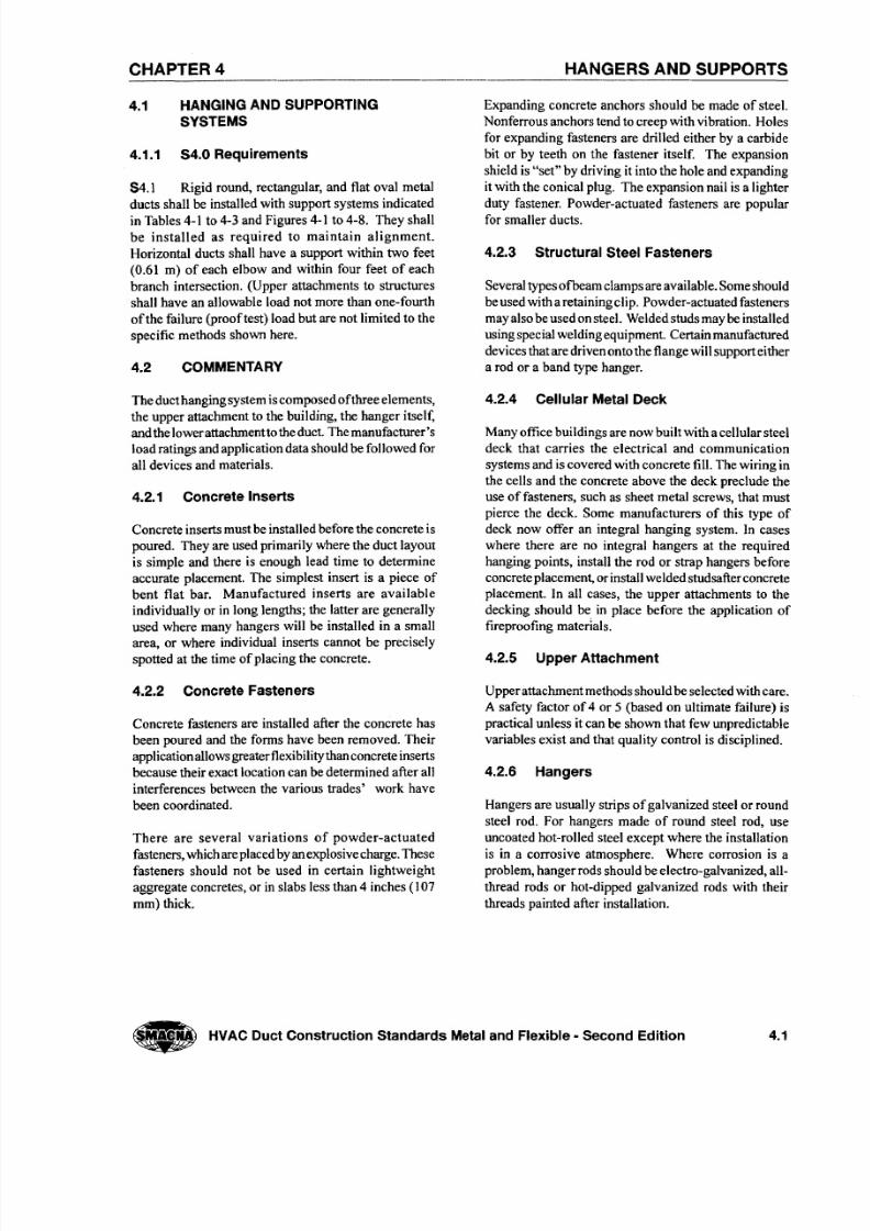
S4.1 Rigid round, rectangular, and flat oval metal
ducts shall be installed with support systems indicatedin Tables 4-1 to 4-3 and Figures 4-1 to 4-8. They shall
be installed as required to maintain alignment.
Horizontal ducts shall have a support within two feet
(0.61 m) of each elbow and within four feet of each
branch intersection. (Upper attachments to structures
shall have an allowable load not more than one-fourth
of the failure (proof test) load but are not limited to the
specific methods shown here.
4.2 COMMENTARY
The duct hanging system iscomposed of three elements,
the upper attachment to the building, the hanger itself,and the lower attachment to the duct. The manufacturer's
load ratings and application data should be followed for
all devices and materials.
4.2.1 Concrete Inserts
Concrete inserts must be installed before the concrete is
poured. They are used primarily where the duct layout
is simple and there is enough lead time to determine
accurate placement. The simplest insert is a piece of
bent flat bar. Manufactured inserts are available
individually or in long lengths; the latter are generally
used where many hangers will be installed in a smallarea, or where individual inserts cannot be precisely
spotted at the time of placing the concrete.
4.2.2 Concrete Fasteners
Concrete fasteners are installed after the concrete has
been poured and the forms have been removed. Their
application allows greater flexibility than concrete inserts
because their exact location can be determined after all
interferences between the various trades' work have
been coordinated.
There are several variations of powder-actuatedfasteners, which are placed by an explosive charge. These
fasteners should not be used in certain lightweight
aggregate concretes, or in slabs less than 4 inches (107
mm) thick.
HANGERS AND SUPPORTS
Expanding concrete anchors should be made of steel.
Nonferrous anchors tend to creep with vibration. Holes
for expanding fasteners are drilled either by a carbide
bit or by teeth on the fastener itself. The expansion
shield is "set" by driving it into the hole and expanding
it with the conical plug. The expansion nail is a lighter
duty fastener. Powder-actuated fasteners are popularfor smaller ducts.
4.2.3 Structural Steel Fasteners
Several types ofbeam clamps are available. Some should
be used with a retaining clip. Powder-actuated fasteners
may also be used on steel. Welded studs may be installed
using special welding equipment. Certain manufactured
devices that are driven onto the flange will support either
a rod or a band type hanger.
4.2.4 Cellular Metal Deck
Many office buildings are now built with a cellular steel
deck that carries the electrical and communication
systems and is covered with concrete fil l. The wiring in
the cells and the concrete above the deck preclude the
use of fasteners, such as sheet metal screws, that must
pierce the deck. Some manufacturers of this type of
deck now offer an integral hanging system. In cases
where there are no integral hangers at the required
hanging points, install the rod or strap hangers before
concrete placement, or install welded studsafterconcrete
placement. In all cases, the upper attachments to the
decking should be in place before the application of
fireproofing materials.
4.2.5 Upper Attachment
Upper attachment methods should be selected with care.
A safety factor of 4 or 5 (based on ultimate failure) is
practical unless it can be shown that few unpredictable
variables exist and that quality control is disciplined.
4.2.6 Hangers
Hangers are usually strips of galvanized steel or round
steel rod. For hangers made of round steel rod, use
uncoated hot-rolled steel except where the installationis in a corrosive atmosphere. Where corrosion is a
problem, hanger rods should be electro-galvanized, all-
thread rods or hot-dipped galvanized rods with their
threads painted after installation.
• HVAC Duct Construction Standards Metaland Flexible - Second Edition 4.1
8/2/2019 Smacna Hangers and Supports
http://slidepdf.com/reader/full/smacna-hangers-and-supports 3/20
4.2.7 Lower Attachment
The lower attachment is the connection between the
hanger and the duct section. Fasteners that penetrate
the duct may be sheet metal screws, blind rivets, or
self-tapping metal screws.
4.2.8 Hanger Spacing
A straight duct section is actually a box section beam
of considerable strength. As in many structures, the
joint is the weakest point, so that is where the support
is. Duct joints, however, are normally strong enough
to permit maximum hanger spacing at 8 (2.44) or 10
foot (3.05 m) intervals, even with one or two
intermediate joints. Very wide ducts require closer
hanger spacing in order to limit individual hangerloads
to safe values. They also require intermediate hangers
to prevent the upper portion of the duct from sagging.
4.2.9 Trapeze Selection
Trapeze members must be selected with careful attention
to the position of the loads on the horizontal bar. Load
analysis is discussed in the notes for Figures 4-4 and
4-5.
4.2.10 Riser Supports
Rectangular risers should be supported by angles or
channels secured to the sides of the duct with welds,
bolts, sheet metal screws, or blind rivets. Here again,
for ducts over 30 inches (762 mm) wide, caution must
be used in fastening the support tothe sheet because the
expansion of the sheet due to internal pressures will
tend to tear the fasteners out. Riser support intervals
should be at one or two story intervals, i.e., 12 feet
(3.66 m) to 24 feet (7.32 m), as suitable for loading.
Another method isto support the riser by its reinforcing.
The load can be transferred to the riser support by angles
or by rods.
4.2.11 Hanging System Selection
The selection of a hanging system should not be taken
lightly not only because it involves a significant portion
of the erection labor, but also because an inadequate
hanging system can be disastrous. In any multiple
hanger system, the failure of one hanger transfers thatits load to adjacent hangers. If one of these fails, an
even greater load is transferred to the next. The result
is a cascading failure in which an entire run of duct
might fall.
There are many hanger alternatives, especially in the
upper attachments. Besides structural adequacy, the
contractor's choice of hanging system must also take
into account the particulars of the building structure,
the skills of the workmen, the availability of tooling,
and the recommendations ofthe fastener manufacturer.
Because of these variables, it is suggested that the
hanging system be the contractor's choice, subject tothe approval of the mechanical engineer.
Figures in this manual show typical hanger
constructions. When special conditions require high
safety factors or the ability to withstand vibrations,
individual concrete or steel attachments can be specified
to be capable of supporting test loads equal to the
minimum rating listed when they are tested in
accordance with methods described by Underwriters'
Laboratory, Inc., for Pipe Hanger Equipment, Bulletin
UL 203, latest edition. See pages 3-19 to 3-21 for
support of flexible duct.
The supports discussed here are not seismicly qualified.
Refer to SMACNA's Seismic Restraint Manual for
additional reinforcement required by earthquake
hazards.
4.2HVAC DuctConstruction Standards Metal and Flexible - Second Edition •
8/2/2019 Smacna Hangers and Supports
http://slidepdf.com/reader/full/smacna-hangers-and-supports 4/20
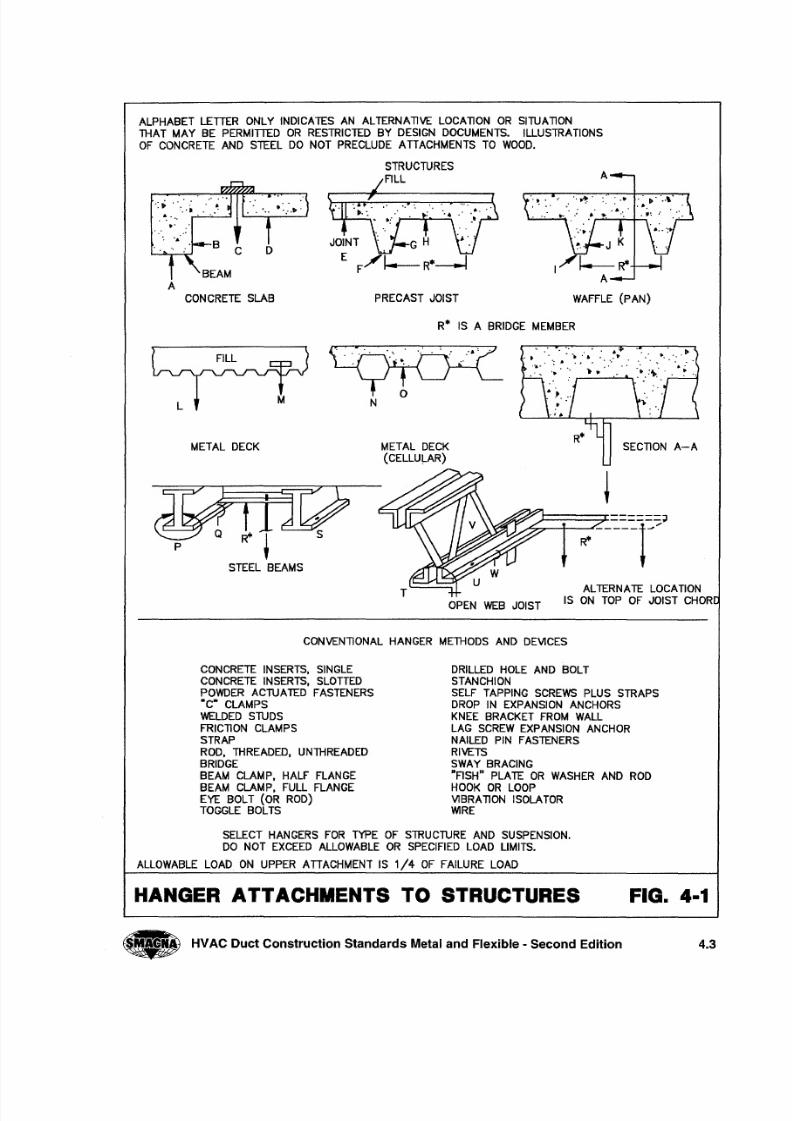
ALPHABET LETTER ONLY INDICATES AN ALTERNAllVE LOCAllON OR SITUAllON
THAT MAY BE PERMITTED OR RESTRICTED BY DESIGN DOCUMENTS. ILLUSTRATIONS
OF CONCRETE AND STEEL DO NOT PRECLUDE ATTACHMENTS TO WOOD.
STRUCTURES
FILL
': ~ _ '~.'.~ .~
~. .'
" ' ' ' :BCD
PRECAST JOIST
A
CONCRETE SLAB
R* IS A BRIDGE MEMBER
~ L M~
. . . . . ..
oN
METAL DECK
STEEL BEAMS
METAL DECK(CELLULAR)
SECllON A-A
OPEN WEB JOIST
ALTERNATE LOCATION
IS ON TOP OF JOIST CHOR
CONVENllONAL HANGER METHODS AND DEVICES
CONCRETE INSERTS, SINGLE
CONCRETE INSERTS, SLOTTEDPOWDER ACTUATED FASTENERS·C· CLAMPS
WELDED STUDS
FRICllON CLAMPS
STRAP
ROD, THREADED, UNTHREADED
BRIDGEBEAM CLAMP, HALF FLANGE
BEAM CLAMP, FULL FLANGE
EYE BOLT (OR ROD)TOGGLE BOLTS
DRILLED HOLE AND BOLTSTANCHION
SELF TAPPING SCREWS PLUS STRAPSDROP IN EXPANSION ANCHORS
KNEE BRACKET FROM WALL
LAG SCREW EXPANSION ANCHORNAILED PIN FASTENERS
RIVETS
SWAY BRACING"FISH" PLATE OR WASHER AND RODHOOK OR LOOP
VlBRAllON ISOLATORWIRE
SELECT HANGERS FOR TYPE OF STRUCTURE AND SUSPENSION.DO NOT EXCEED ALLOWABLE OR SPECIFIED LOAD LIMITS.
ALLOWABLE LOAD ON UPPER ATTACHMENT IS 1/4 OF FAILURE LOAD
HANGER ATTACHMENTS TO STRUCTURES FIG. 4-1
HVAC Duct Construction Standards Metal and Flexible - Second Edition 4.3
8/2/2019 Smacna Hangers and Supports
http://slidepdf.com/reader/full/smacna-hangers-and-supports 5/20
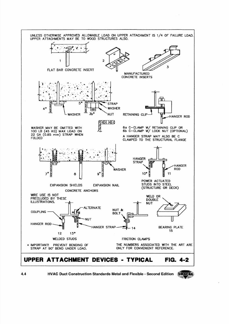
UNLESS OTHERWISE APPROVED ALLOWABLE LOAD ON UPPER ATTACHMENT IS 1/4 OF FAILURE LOAD.UPPER ATTACHMENTS MAY BE TO WOOD STRUCTURES ALSO.
2
FLAT BAR CONCRETE INSERT
MANUFACTURED
CONCRETE INSERTS
, "J:" ..i : ...... . . ....
t • ". ..'
. . . . . . .. ; / : . ~ . " ~ . ~ : ..: ...•...'. ~.~:. '-~. .
~, .:.. , ;0"., ,
• E3D---~~~~~~~STRAP
WASHERNUT
, '
':, • ,.', '. rI,,' ,
4*
RETAINING CLIPHANGER ROD
6a C-CLAMP wi RETAINING CLIP OR
6b C-CLAMP W I LOCK NUT (OPTIONAL)
A HANGER STRAP MAY ALSO BE C
CLAMPED TO THE STRUCTURAL FLANGE
WASHER MAY BE OMITTED WITH100 LB (45 KG) MAX LOAD ON
22 GA (0.85 mm) STRAP WHEN
FOLDED
HANGERSTRAP
HANGERROD
10*
EXPANSION SHIELDS EXPANSION NAIL
CONCRETE ANCHORS
POWER ACTUATED
STUDS INTO STEEL
(STRUCTURE OR DECK)
WIRE USE IS NOT
PRECLUDED BY THESE
ILLUSTRATIONS.
WELD OR
DOUBLE
NUT
ALTERNATENUT &
BOLTOUPLING
HANGER RODNUT
"""___HANGER STRAP _ _,.. BEARING PLATE
1512 13'"
WELDED STUDS
'" IMPORTANTI PREVENT BENDING OFSTRAP AT 90' BEND UNDER LOAD.
FRICTION CLAMPS
THE NUMBERS ASSOCIATED WITH THE ART ARE
ONLY FOR CONVENIENT REFERENCE.
UPPER ATT ACHMENT DEVICES - TYPICAL FIG. 4-2
4 . 4 HVAC Duct Construction Standards Metal and Flexible - Second Edition •
8/2/2019 Smacna Hangers and Supports
http://slidepdf.com/reader/full/smacna-hangers-and-supports 6/20
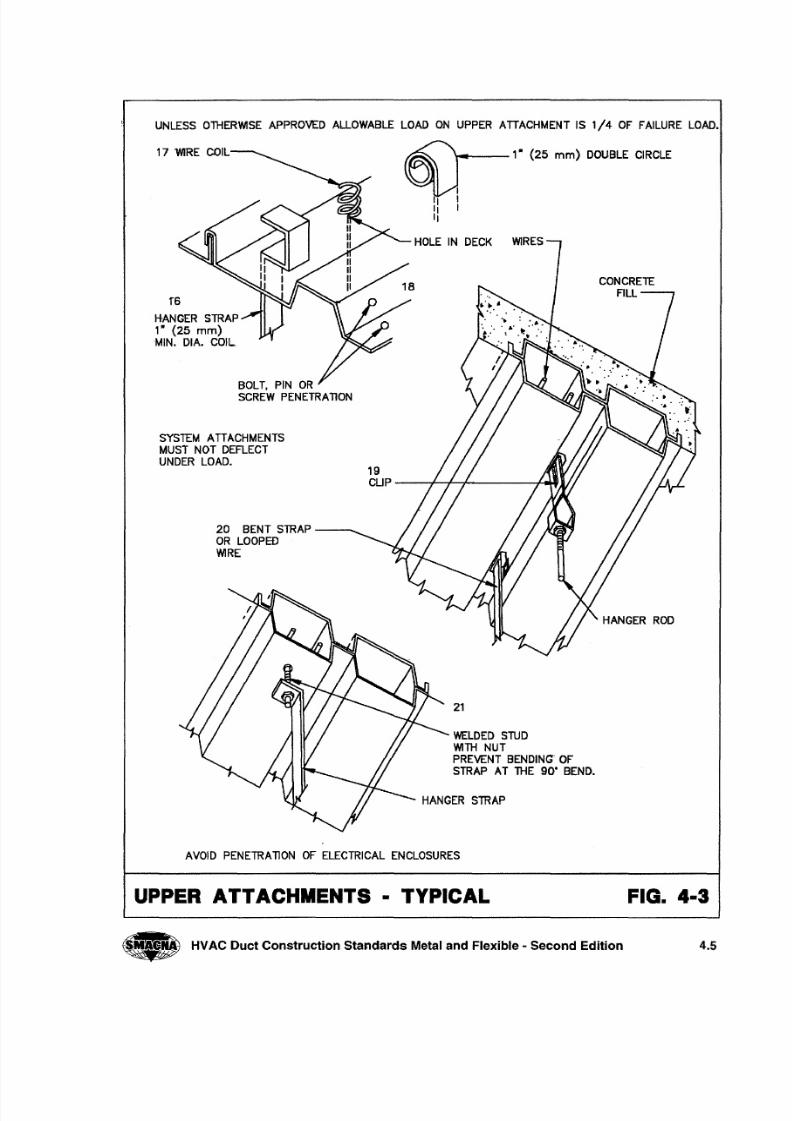
UNLESS O TH ERW ISE A PPRO VED A LLOWA BLE LO AD O N UPPER A TTA CHM ENT IS 1/4 O F FA ILURE LO AD.
WIRESOLE IN DECK
CONCRETEFILL
1 "6
H-ANGER STRAP1· (25 mm)M IN. DIA . CO IL
BOLT, PIN ORSCREW PENETRAT ION
SYSTEM ATTACHMENTSMUS T N OT D EFLE CTUNDER LOAD .
19CUp----T-~~------~~
20 BENT STRAP -- .. .. ._O R LOOP EDWIRE
H AN GE R R OD
21
WELDED STUDW IT H NUT
PRE VENT B ENDING OFSTRAP AT THE 90· BEND.
H ANGER STRAP
AVOID PENETRAT ION OF ELECTRIC A L ENCLOSURES
UPPER ATTACHMENTS - TYPICAL FIG. 4-3
• HVAC Duct Construction Standards Metal and Flexible - Second Edition 4.5
8/2/2019 Smacna Hangers and Supports
http://slidepdf.com/reader/full/smacna-hangers-and-supports 7/20
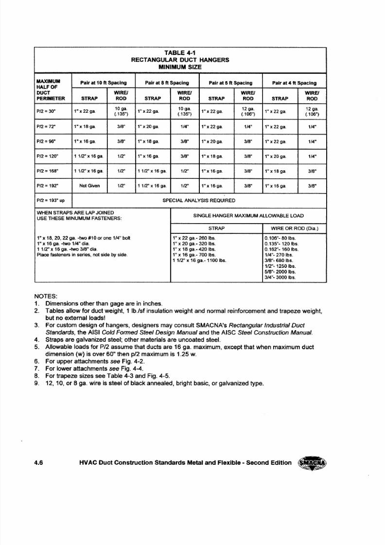
TABLE 4-1
RECTANGULAR DUCT HANGERS
MINIMUM SIZE
MAXIMUM Pair at 10ft Spacing Pair at 8 ft Spacing Pair at 5 ft Spacing Pair at 4 ft SpacingHALF OF
DUCT WIREI WIREI WIREI WIREIPERIMETER STRAP ROD STRAP ROD STRAP ROD STRAP ROD
PI2 = 30" 1" x 22 gao10 gao
1"x22ga.10 gao
1" x 22 ga.12 ga.
1"x22ga.12 gao
(.135") (.135") (.106") (.106")
PI2 = 72" 1"x18ga. 3/8" 1"x20ga. 1/4" 1" x 22 ga. 1/4" 1"x22ga. 1/4"
PI2 = 96" 1"x16ga. 3/8" 1"x 18ga. 3/8" 1"x20ga. 3/8" 1" x 22 gao 1/4"
P/ 2 = 120" 1 112" x 16 gao 1/2" 1"x16ga. 3/8" 1"x 18ga. 3/8" 1" x 20 ga. 1/4"
PI2 = 168" 1 1/2" x 16 gao 1/2" 1 1/2" x 16 gao 1/2" 1"x 16ga. 3/8" 1" x 18 gao 3/8"
PI2 = 192" Not Given 112" 1 1/2" x 16 ga" 112" 1"x 16ga. 3/8" 1"x 16ga. 3/8"
PI2 = 193" up SPECIAL ANALYSIS REQUIRED
WHEN STRAPS ARE LAP JOINEDSINGLE HANGER MAXIMUM ALLOWABLE LOAD
USE THESE MINUMUM FASTENERS:
STRAP WIRE OR ROD (Dia.)
1" x 18, 20, 22 gao - two #10 or one 1/4" bolt 1" x 22 ga.- 260 Ibs. 0.106"- 80 Ibs.
1" x 16 gao- two 1/4" dia. 1" x 20 ga.- 320 Ibs. 0.135"- 120 Ibs"
1 1/2" x 16 gao -two 3/8" dia" 1" x 18 ga.- 420 Ibs. 0.162"- 160 Ibs.
Place fasteners in series, not side by side. 1" x 16 ga.- 700 Ibs. 114"- 270 Ibs.
1 1/2" x 16 ga.- 1100 Ibs. 3/8"- 680 Ibs.
112"- 1250 Ibs.
5/8"- 2000 Ibs.
3/4"- 3000 Ibs.
NOTES:
1. Dimensions other than gage are in inches.
2. Tables allow for duct weight, 1 Ib./sf insulation weight and normal reinforcement and trapeze weight,
but no external loads!
3. For custom design of hangers, designers may consult SMACNA's Rectangular Industrial Duct
Standards, the AISI Cold Formed Steel Design Manual and the AISC Steel Construction Manual.
4. Straps are galvanized steel; other materials are uncoated steel.
5. Allowable loads for P /2 assume that ducts are 16 gao maximum, except that when maximum duct
dimension (w) is over 60" then p/2 maximum is 1.25 W.
6. For upper attachments see Fig. 4-2.
7. For lower attachments see Fig. 4-4.8. For trapeze sizes see Table 4-3 and Fig. 4-5.
9. 12, 10, or 8 gaowire is steel of black annealed, bright basic, or galvanized type.
4 . 6 HVAC Duct Construction Standards Metal and Flexible - Second Edition •
8/2/2019 Smacna Hangers and Supports
http://slidepdf.com/reader/full/smacna-hangers-and-supports 8/20
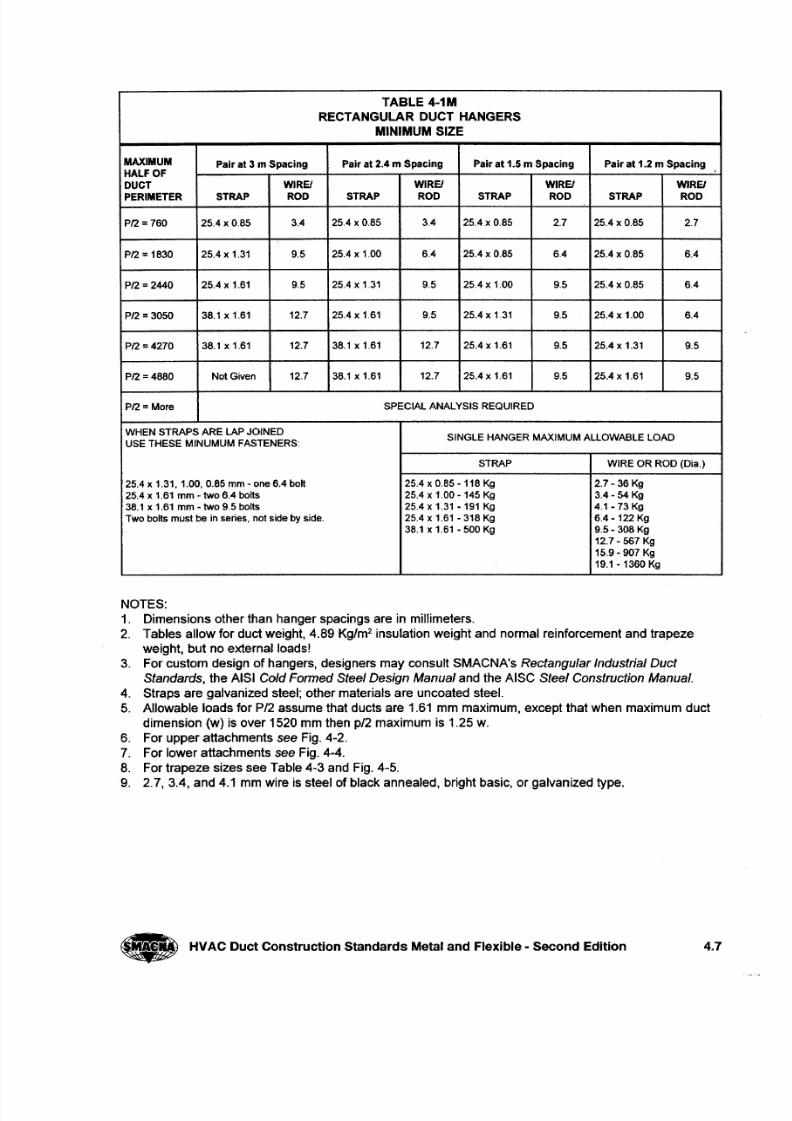
TABLE 4-1M
RECTANGULAR DUCT HANGERS
MINIMUM SIZE
MAXIMUM Pair at 3 m Spacing Pair at 2.4 m Spacing Pair at 1.5 m Spacing Pair at 1.2 m SpacingHALF OF
DUCT WIRE! WIREI WIRE! WIREIPERIMETER STRAP ROD STRAP ROD STRAP ROD STRAP ROD
PI2 = 760 25.4 x 0.85 3.4 25.4 x 0.85 3.4 25.4 x 0.85 2.7 25.4 x 0.85 2.7
PI2 = 1830 25.4 x 1.31 9.5 25.4 x 1.00 6.4 25.4 x 0.85 6.4 25.4 x 0.85 6.4
P /2 = 2440 25.4 x 1.61 9.5 25.4 x 1.31 9.5 25.4 x 1.00 9.5 25.4 x 0.85 6.4
P/ 2 = 3050 38.1 x 1.61 12.7 25.4 x 1.61 9.5 25.4 x 1.31 9.5 25.4 x 1.00 6.4
PI2 = 4270 38.1 x 1.61 12.7 38.1 x 1.61 12.7 25.4 x 1.61 9.5 25.4 x 1.31 9.5
PI2 =4880 Not Given 12.7 38.1 x 1.61 12.7 25.4 x 1.61 9.5 25.4 x 1.61 9.5
PI2 = More SPECIAL ANALYSIS REQUIRED
WHEN STRAPS ARE LAP JOINEDSINGLE HANGER MAXIMUM ALLOWABLE LOAD
USE THESE MINUMUM FASTENERS:
STRAP WIRE OR ROD (Dia.)
25.4 x 1.31,1.00,0.85 mm - one 6.4 boll 25.4 x 0.85 -118 Kg 2.7 -36 Kg
25.4 x 1.61 mm - two 6.4 bolts 25.4 x 1.00 -145 Kg 3.4 - 54 Kg
38.1 x 1.61 mm - two 9.5 bolts 25.4 x 1.31 -191 Kg 4.1-73 Kg
Two boils must be in series, not side by side. 25.4 x 1.61 - 318 Kg 6.4-122 Kg
38.1 x 1.61 - 500 Kg 9.5- 308 Kg
12.7 - 567 Kg
15.9 - 907 Kg
19.1 - 1360 Kg
NOTES:
1. Dimensions other than hanger spacings are in millimeters.
2. Tables allow for duct weight, 4.89 Kg/m2 insulation weight and normal reinforcement and trapeze
weight, but no external loads!
3. For custom design of hangers, designers may consult SMACNA's Rectangular Industrial Duct
Standards, the AISI Cold Formed Steel Design Manual and the AISC Steel Construction Manual.
4. Straps are galvanized steel; other materials are uncoated steel.
5. Allowable loads for P /2 assume that ducts are 1.61 mm maximum, except that when maximum duct
dimension (w) is over 1520 mm then p/2 maximum is 1.25 w.
6. For upper attachments see Fig. 4-2.
7. For lower attachments see Fig. 4-4.
8. For trapeze sizes see Table 4-3 and Fig. 4-5.
9. 2.7, 3.4, and 4.1 mm wire is steel of black annealed, bright basic, or galvanized type.
HVAC Duct Construction Standards Metal and Flexible - Second Edition 4.7
8/2/2019 Smacna Hangers and Supports
http://slidepdf.com/reader/full/smacna-hangers-and-supports 9/20
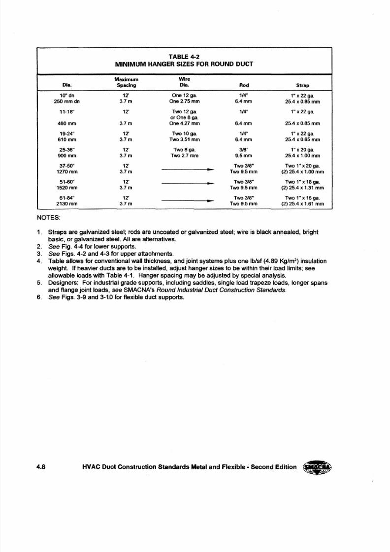
TABLE 4-2
MINIMUM HANGER SIZES FOR ROUND DUCT
Maximum Wire
Dia. Spacing Dia. Rod Strap
10" dn 12' One 12ga. 1/4" 1"x 22gao250mmdn 3.7m One 2.75 mm 6.4mm 25.4 x 0.S5mm
11-1S" 12' Two 12ga. 1/4" 1"x 22gao
or One Sga.
460mm 3.7m One4.27mm 6.4mm 25.4 x 0.S5mm
19-24" 12' Two 10ga. 1/4" 1"x 22gao
610mm 3.7m Two 3.51 mm 6.4mm 25.4 x 0.S5mm
25-36" 12' TwoSga. 3/S" 1"x20ga.
900mm 3.7m Two2.7mm 9.5mm 25.4 x 1.00 mm
37-50" 12' Two 3/S" Two 1" x 20 gao
1270mm 3.7m Two9.5mm (2) 25.4 x 1.00mm
51-60" 12' Two 3IS" Two 1" x 1Sgao
1520mm 3.7m Two9.5mm (2) 25.4 x 1.31 mm
61-84" 12' Two 3/S" Two 1" x 16gao
2130mm 3.7m Two9.5mm (2) 25.4 x 1.61 mm
NOTES:
1. Straps are galvanized steel; rods are uncoated or galvanized steel; wire is black annealed, bright
basic, or galvanized steel. All are alternatives.
2. See Fig. 4-4 for lower supports.
3. See Figs. 4-2 and 4-3 for upper attachments.
4. Table allows for conventional wall thickness, and joint systems plus one Iblsf (4.89 Kg/m2) insulation
weight. If heavier ducts are to be installed, adjust hanger sizes to be within their load limits; see
allowable loads with Table 4-1. Hanger spacing may be adjusted by special analysis.
5. Designers: For industrial grade supports, including saddles, single load trapeze loads, longer spans
and flange joint loads, see SMACNA's Round Industrial Duct Construction Standards.
6. See Figs. 3-9 and 3-10 for flexible duct supports.
4.8 HVAC Duct Construction Standards Metal and Flexible· Second Edition _
8/2/2019 Smacna Hangers and Supports
http://slidepdf.com/reader/full/smacna-hangers-and-supports 10/20
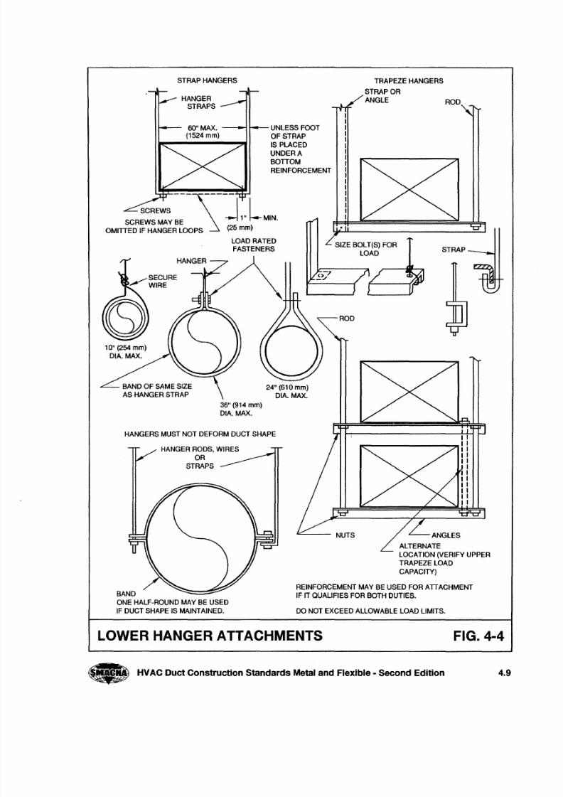
STRAP HANGERS
SCREWS - - - ~ - - - - J - LSCREWS MAY BE 1" MIN.
OMITTED IF HANGER LOOPS (25 mm)
LOAD RATED
FASTENERS
36" (914 mm)DIA.MAX.
HANGERS MUST NOT DEFORM DUCT SHAPE
HANGER RODS, WIRES
OR
STRAPS
BAND
ONE HALF-ROUND MAY BE USED
IF DUCT SHAPE IS MAINTAINED.
TRAPEZE HANGERS
STRAP OR
ANGLE ROD
UNLESS FOOT
OF STRAP
IS PLACED
UNDER A
BOTTOM
REINFORCEMENT
24" (610 mm)
DIA.MAX.
ALTERNATE
LOCATION (VERIFY UPPER
TRAPEZE lOAD
CAPACITY)
REINFORCEMENT MAY BE USED FOR ATTACHMENT
IF IT QUALIFIES FOR BOTH DUTIES.
DO NOT EXCEED AllOWABLE LOAD LIMITS.
LOWER HANGER ATTACHMENTS FIG. 4-4
., HVACDuct Construction Standards Metal and Flexible - Second Edition 4.9
8/2/2019 Smacna Hangers and Supports
http://slidepdf.com/reader/full/smacna-hangers-and-supports 11/20
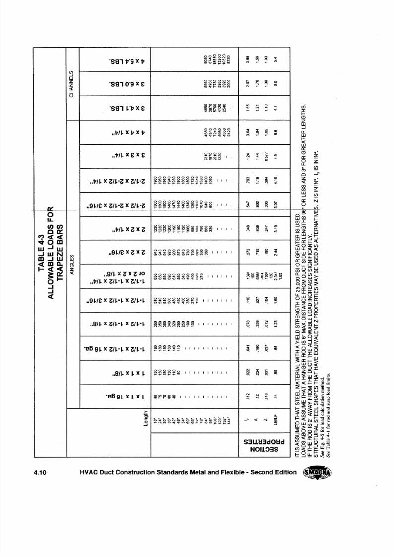
~~~g~g '" '" <'> . . .'sal t·sx t O,.._CON(x)('f') '"
on ~ .,;c)CD~~~<D
,.; ~ ~
C/)
..J
W000000
Z . . . CO IX)0
'sal 0'9x £tOLOX)( ')NO 0 ": ~
Z (J)C)f'-.C)C)O .;
- clll~f'-.lOMN N ~
: r : :o
00000 co~
0 ~'sal ~·tX £ U')t---WN~
I "!J) CO ,.._ ..... U) .. rvMlOvN
000000 . . . . . . onCOIIt/~ x tXt covvlt)Ll)N 0 ~ ~,f)('f')Nc)M"¢ ,.; .;
voq- ..... IO'O!tN
IIt/~ X£x c 0000 . . . . . . . . ............. . . .
'"(D&ON I I N ": on .. rN.....N..... ~ ~ 0
0000000000000 <'> '". . . ~..t/~ x (;/~-(; x (;/~-(; ~~~~~5:~~~~~~~ I I I I 0 '". . . . . . . . . . . . . . . . . . . . . . . . . . . . . . . . . . . . . . . . . . . . . . . . . . . . . ": ~ .. r
g88~~~g~g~:2~8 . . . N <'> e-
..9~/£ x (;H-(; x (;/~-(; I I I I . . . 0 0 0
....0 := --- .~ ~ ~ : : : ! : ~ : ! ~ ~ : : ~ C ) ( [ ) ~ ~ <'> ,.;
0u,
U) U) 0000000000000 ec ., . . . ~..t/~ x (; x (; §aa~~~~~mfi~~~ I I I I . . . M . . .0: : : ~ ~ "! ,.;
M««~ 0mw ..J W 000000000000 N on 0 . . ...J W N ..9H£x (; x (; "ItvvNO .....COONO<D I I I I I . . .
'". . .
C/)C) C) C) C) C) (0CD ,.........o lO M "! ": N
m ..J w w
«m a . . ..J
C)
I-
~ ~z« 118/~ x (; x (; JO 00000000000 ~:$~~~g~~O UlLON .....o'¢' (J)O N .....I I I I I I
0I-
..tH x (;H-~ x (;/~-~
COCO(O(D(olOlllvvMN '""-;'""-;~-.;r:""'":-:N"":
..J
..J- e
..9~/£ x (;H-~ x (;/~-~0000000000 ~ . . . . . . 0...............CDIOOIt),.._O'J I I I I I I I N 0 CD
lOltlLOl.OvvvMN ..... ~ ~
..8/~ x (;/~-~x (;H-~ 000000000 '" '"N <'>
~~~~~~~~~ I I I I I I I I . . .'"
. . . "!~ ~ ~ ~
'e B 9~x (;H-~x (;/~-~000000 0
,. _<0
~~~~:!;: I I I I I I I I I I I (!; <0 <'>"!
~~~~~~N . . . ;;; 0
118/~ x ~x ~ I I I I I I I I I I I N <'>
~ "! ~ ~
'e B 9~x ~x ~ OOOOON
N<0 . . .
CO"'_"'_"'v I I I I I I I I I I I I C ; C ; -e -
s:
0, U.
c: ~~b~~~~b~~~~~~~~:_ .
-c N c :!Q) m..J
~N<'>M ...... " '< O< O, . _ . .. <O"'~~~~ .j
S3IUI3dOl:id
NOI103S
cr i: r : :f0-e . ' : )
ZW..J
e x :Wfo-«we x :oe x :
f r
4.10 HVAC Duct Construction Standards Metal and Flexible - Second Edition .,
8/2/2019 Smacna Hangers and Supports
http://slidepdf.com/reader/full/smacna-hangers-and-supports 12/20
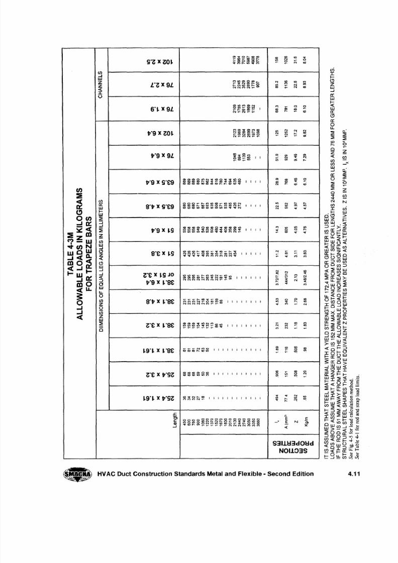
(J)....I
WZ
~I
U
L O " " X 9 LfD M
N 0>N .,;
6°~x 9 Lo ~.,; .- '"
t0 9 x " " O ~N
'",;
t0 9 x 9 L
t0 9 x SO£9
~WI-W:: E
::J....I
:il~(J)
W....I
C >z«C >w....I
....I
: 3owu ..o(J)
zoC i5zw:: E
5
gO t x SO£9
t0 9 x ~S
",,0£x ~SJOt0 9 x ~og£
I I I I I I I I I I I
o-e -M
N
M
N.. ,N
eo
I I I I I I I I I I I
1 : E.:» ,S N ~
«
I I I I I I I t I I I I
S 3 1 1 1 : : 1d O l : : l d
N O I J . 0 3 S
• HVAC Duct Construction Standards Metal and Flexible - Second Edition 4011
8/2/2019 Smacna Hangers and Supports
http://slidepdf.com/reader/full/smacna-hangers-and-supports 13/20
r - - -W-I
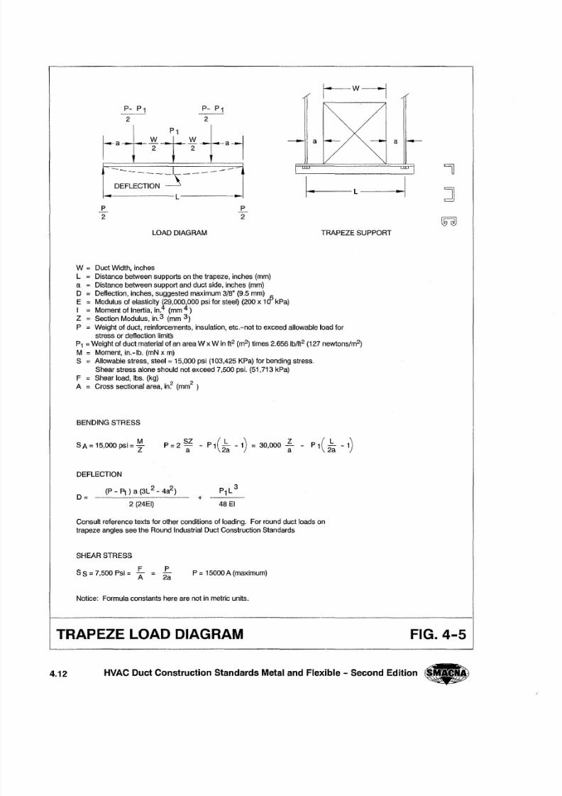
lOAD DIAGRAM TRAPEZE SUPPORT
a
I - - - - -l~~1
4.12 HVAC Duct Construction Standards Metal and Flexible - Second Edition
ra---- ~-
W
2-- a
--_ ------DEFlECTIO~ : = . . _ s -
~-------l---------
P
2
P
2
W = Duct Width, inchesl Distance between supports on the trapeze, inches (mm)
Distance between support and duct side, inches (mm)
Deflection, inches, suggested maximum 3 /S" (9.5 mm) 6
Modulus of elasticity 129,000,000 psi for steel) (200 x 10 kPa)
Moment of Inertia, in.4 (mm 4 )
Section Modulus, in.3 (mm 3)
P Weight of duct, reinforcements, insulation, etc.-not to exceed allowable load for
stress or def lect ion l imits
P1 =Weight of duct material of an area W x W in ft2 (m2) times 2.6561b/ft2 (127 newtons/m2)
M Moment, in.-Ib. (mN x m)
S Allowable stress, steel = 15,000 psi (103,425 KPa) for bending stress.
Shear stress alone should not exceed 7,500 psi . (51,713 kPa)
F Shear load, Ibs. (kg)
A Cross sectional area, in~ (mm2)
aD
E
I
Z
BENDING STRESS
SA = 15,000 psi = ~Z
P=2SZ
_ P1(_b_ -1) = 30000."£ - P1(_b_ -1)a 2a 'a 2a
DEFLECTION
(P - P t ) a (3l2 - 4a2)D = - -- -- -- - - -- -- -- -
2 (24EI)+
Consul t re ference texts for other conditions of loading. For round duct loads on
trapeze angles see the Round Industr ial Duct Construct ion Standards
SHEAR STRESS
S S = 7,500 Psi = ~P
2aP = 15000 A (maximum)
Notice: Formula constants here are not in metric uni ts.
TRAPEZE LOAD DIAGRAM
J ]
FIG. 4-5
8/2/2019 Smacna Hangers and Supports
http://slidepdf.com/reader/full/smacna-hangers-and-supports 14/20
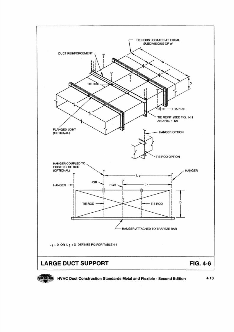
TIE RODS LOCATED AT EQUAL
SUBDIVISIONS OF W
DUCT REINFORCEMENT
TIE REINF. (SEE FIG. 1-11
AND FIG. 1-12)
FLANGED JOINT
(OPTIONAL) i---ANGER OPTION
1
1
• HVACDuctConstructionStandardsMetal andFlexible· SecondEdition 4.13
TIE ROD OPTION
HANGER COUPLED TO ~EXISTING TIE ROD
(OPTIONAL) rV
HANGER
T 1-------- L2--------<-
1 1 71 HGR .........
HANGER --.I i HGR ~I--.---- L 1------1
HANGER AIT ACHED TO TRAPEZE BAR
L1 + 0 OR L 2 + D DEFINES P /2 FOR TABLE 4-1
LARGE DUCT SUPPORT FIG. 4-6
8/2/2019 Smacna Hangers and Supports
http://slidepdf.com/reader/full/smacna-hangers-and-supports 15/20
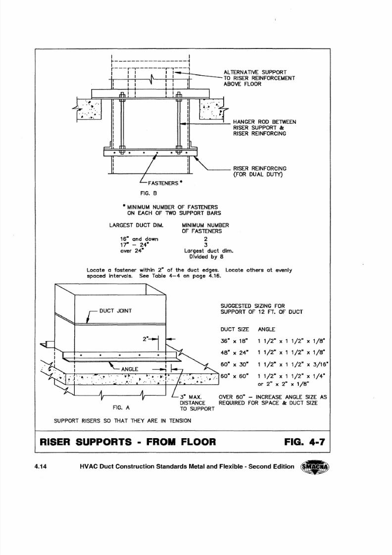
RISER SUPPORTS • FROM FLOOR FIG. 4·7
.-,ft----..;.._ HANGER ROD BETWEENRISER SUPPORT B eRISER REINFORCING
'-- __ RISER REINFORCING
(FOR DUAL DUlY)
FIG. B
...MINIMUM NUMBER OF FASTENERS
ON EACH OF TWO SUPPORT BARS
LARGEST DUCT DIM.
lS" and down
17" - 24"
over 24·
MINIMUM NUMBEROF FASTENERS
23
Largest duct dim.
Divided by 8
Locate a fastener within 2" of the duct edges. Locate others at evenlyspaced intervals. See Table 4-4 on page 4.1S.
SUGGESTED SIZING FOR
SUPPORT OF 12 FT. OF DUCT
DUCT SIZE ANGLE
36· x 18" 1/2" x 1 1/2" x 1/8-
48" x 24- 1/2" x 1 1/2" x 1/8-
SO" x 30" 1/2" x 1 1/2" x 3/16"
60· x 60" 1/2" x 1 1/2" x 1/4·or 2" x 2" x l/S"
FIG. A
3" MAX. OVER 60" - INCREASE ANGLE SIZE AS
DISTANCE REQUIRED FOR SPACE B e DUCT SIZE
TO SUPPORT
SUPPORT RISERS SO THAT THEY ARE IN TENSION
4.14 HVAC Duct Construction Standards Metal and Flexible - Second Edition •
8/2/2019 Smacna Hangers and Supports
http://slidepdf.com/reader/full/smacna-hangers-and-supports 16/20
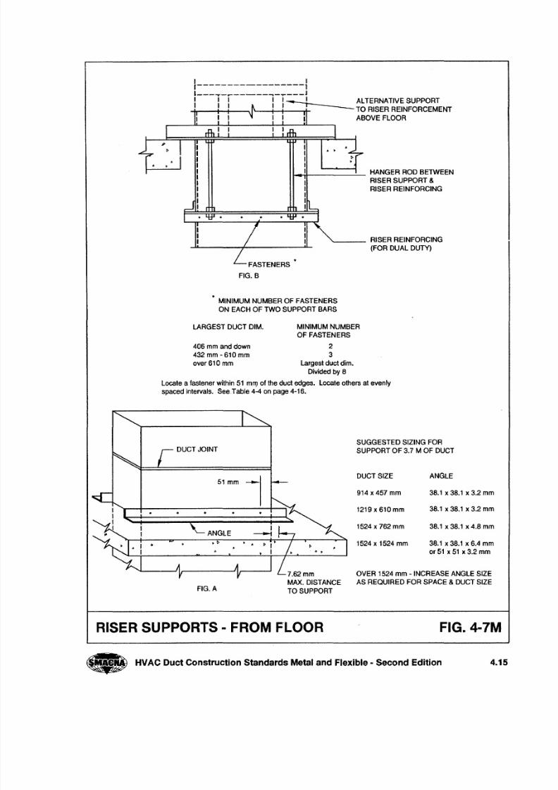
I Ir-----------------1l ~-_-----_- .....--J
I I I I I I ALTERNATIVE SUPPORT
I I I I ,-r--- TO RISER REINFORCEMENT
I I ABOVE FLOOR
...-1+------ HANGER ROD BETWEEN
RISER SUPPORT &
RISER REINFORCING
'-- __ RISER REINFORCING
(FOR DUAL DUTy)
MINIMUM NUMBER OF FASTENERS
ON EACH OF TWO SUPPORT BARS
MINIMUM NUMBER
OF FASTENERS
2
3
Largest duct dim.
Divided by 8
Locate a fastener within 51 mil } of the duct edges. Locate others at evenly
spaced intervals. See Table 4-4 on page 4-16.
LARGEST DUCT DIM.
406 mm and down
432 mm - 610 mm
over 610 mm
51 mm --DUCT SIZE ANGLE
SUGGESTED SIZING FOR
SUPPORT OF 3.7 M OF DUCT
ANGLE
OVER 1524 mm -INCREASE ANGLE SIZE
AS REQUIRED FOR SPACE & DUCT SIZE
914 x 457 mm 38.1 x 38.1 x 3.2 mm
1219 x 610 mm 38.1 x 38.1 x 3.2 mm
1524 x 762 mm 38.1 x 38.1 x 4.8 mm
1524 x 1524 mm 38.1 x 38.1 x 6.4 mm
or 51 x 51 x 3.2 mm.
7.62mm
MAX. DISTANCE
TO SUPPORTIG. A
RISER SUPPORTS - FROM FLOOR FIG.4-7M
• HVAC Duct Construction Standards Metal and Flexible· Second Edition 4.15
8/2/2019 Smacna Hangers and Supports
http://slidepdf.com/reader/full/smacna-hangers-and-supports 17/20
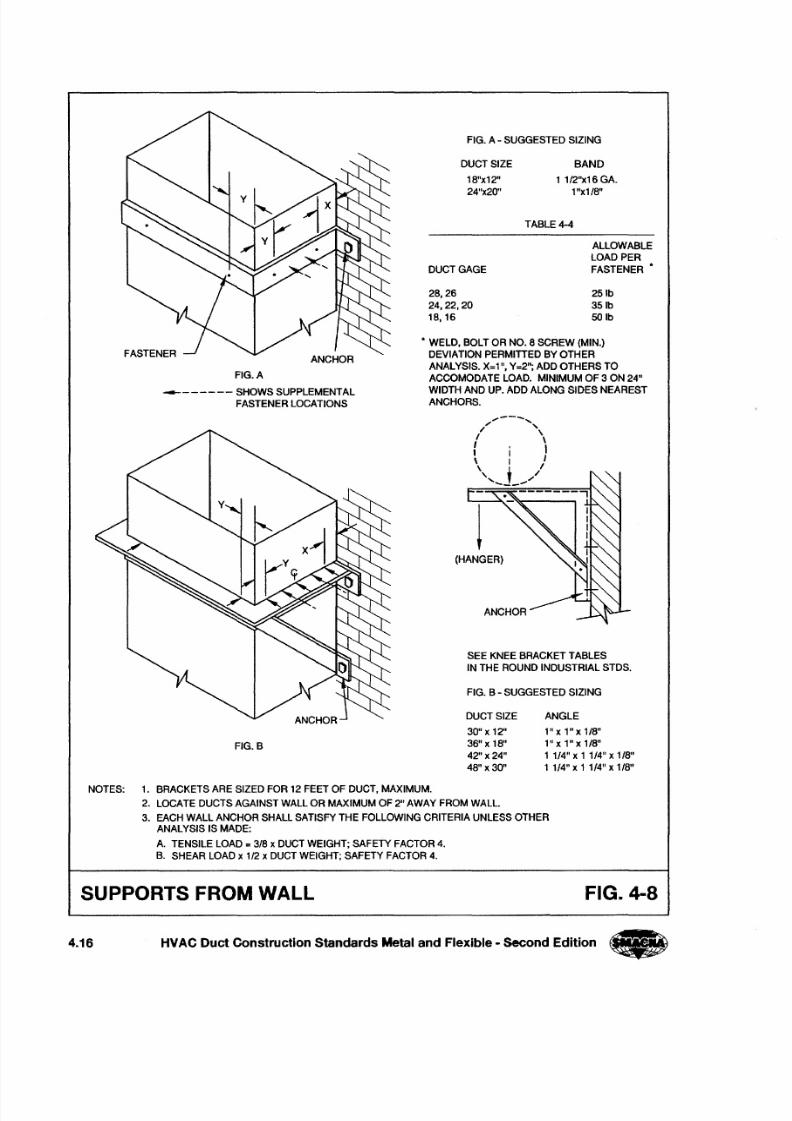
ANCHOR
FIG. A
-- - - - - - - SHOWS SUPPLEMENTAL
FASTENER LOCATIONS
FIG.B
FIG. A - SUGGESTED SIZING
DUCT SIZE BAND
1 1/2"x16 GA.
1"x1/S"
1S"x12"
24"x20"
TABLE 4-4
DUCT GAGE
ALLOWABLE
LOAD PER
FASTENER·
2S,26
24,22,20
1S.16
251b
351b
50Ib
• WELD. BOLT OR NO. S SCREW (MIN.)
DEVIATION PERMITTED BY OTHER
ANALYSIS. X=1", Y=2"; ADD OTHERS TO
ACCOMODATE LOAD. MINIMUM OF 3ON 24"WIDTH AND UP. ADD ALONG SIDES NEAREST
ANCHORS.
",,,--' . . . . ., ,I \
\I , II I I\ I I
\ , /, '"- . . . . _ - , , -
(HANGER)
SEE KNEE BRACKET TABLES
IN THE ROUND INDUSTRIAL STDS.
FIG. B - SUGGESTED SIZING
DUCT SIZE ANGLE
30" x 12"
36" x 1S"
42" x 24"
4S" x 30"
1"x1"x1/S"
l"x 1"x lIS"
1 1/4" xl 1/4" x 1/S"
1 1/4" x 1 114" x lIS"
NOTES: 1. BRACKETS ARE SIZED FOR 12 FEET OF DUCT. MAXIMUM.
2. LOCATE DUCTS AGAINST WALL OR MAXIMUM OF 2" AWAY FROM WALL.
3. EACH WALL ANCHOR SHALL SATISFY THE FOLLOWING CRITERIA UNLESS OTHER
ANALYSIS IS MADE:
A. TENSILE LOAD = 3/ S x DUCT WEIGHT; SAFETY FACTOR 4.
B. SHEAR LOAD x 1/ 2 x DUCT WEIGHT; SAFETY FACTOR 4.
SUPPORTS FROM WALL FIG. 4-8
4.16 HVAC Duct Construction Standards Metal and Flexible - Second Edition
8/2/2019 Smacna Hangers and Supports
http://slidepdf.com/reader/full/smacna-hangers-and-supports 18/20
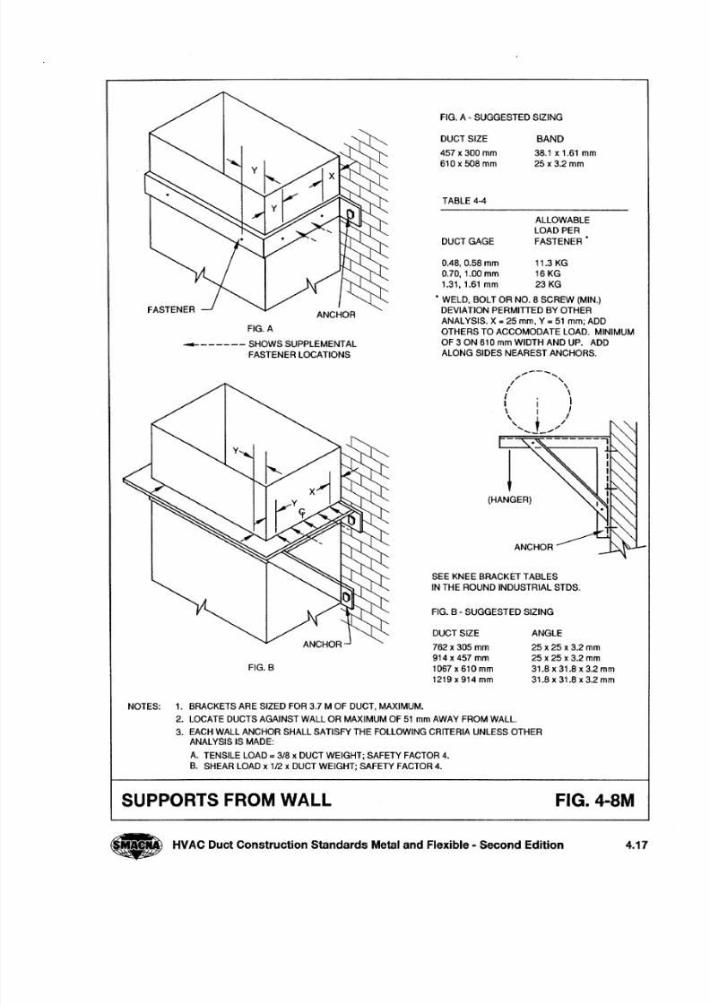
FIG. A - SUGGESTED SIZING
DUCT SIZE
457 x 300 mm
610 x 508 mm
BAND
38.1 x 1.61 mm
25 x3.2 mm
TABLE 4-4
DUCT GAGE
ALLOWABLE
LOAD PER
FASTENER'
0.48, 0.58 mm 11.3 KG
0.70, 1.00 mm 16 KG
1.31.1.61mm 23 KG
• WELD, BOLT OR NO.8 SCREW (MIN.)
DEVIATION PERMITTED BY OTHER
ANALYSIS. X =2 5 mm, Y = 51 mm; ADD
OTHERS TO ACCOMODATE LOAD. MINIMUM
OF 3 ON 610 mm WIDTH AND UP. ADD
ALONG SIDES NEAREST ANCHORS.
ANCHOR
FIG. A
-------- SHOWS SUPPLEMENTAL
FASTENER LOCATIONS
.,--- . . . . ., ,/ \I \
I , II I I\ I I
\ ~ /
" , -'. . . . . ._-"
(HANGER)
SEE KNEE BRACKET TABLES
IN THE ROUND INDUSTRIAL STDS.
FIG. B - SUGGESTED SIZING
DUCT SIZE
762 x 305 mm
914 x 457 mm
1067 x 610 mm
1219 x 914 mm
ANGLE
25 x 25 x 3.2 mm
25 x 25 x 3.2 mm
31.8 x 31.8 x 3.2 mm
31.8 x 31.8 x 3.2 mm
FIG.B
NOTES: 1. BRACKETS ARE SIZED FOR 3.7 M OF DUCT, MAXIMUM.
2. LOCATE DUCTS AGAINST WALL OR MAXIMUM OF 51 mm AWAY FROM WALL.
3. EACH WALL ANCHOR SHALL SATISFY THE FOLLOWING CRITERIA UNLESS OTHER
ANALYSIS IS MADE:
A. TENSILE LOAD = 318 x DUCT WEIGHT; SAFETY FACTOR 4.
B. SHEAR LOAD x 112x DUCT WEIGHT; SAFETY FACTOR 4.
SUPPORTS FROM WALL FIG.4-SM
• HVAC Duct Construction Standards Metal and Flexible - Second Edition 4.17
8/2/2019 Smacna Hangers and Supports
http://slidepdf.com/reader/full/smacna-hangers-and-supports 19/20
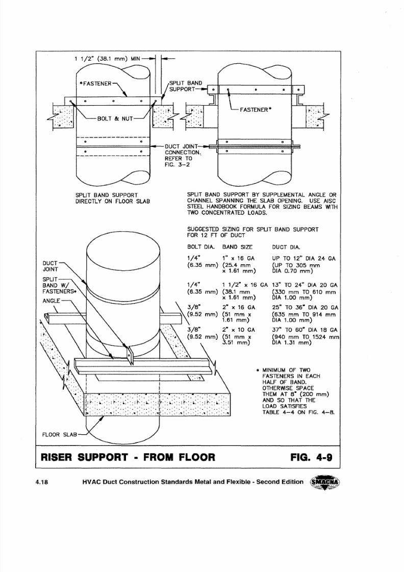
o o
FASTENER·
o
o D
o oF========::f--DUCT JOINT-~~~~~~~~§Fr5
CONNECTION. 0
REFER TO '
FIG. 3-2
SPLIT BAND SUPPORTDIRECTLY ON FLOOR SLAB
SPLIT BAND SUPPORT BY SUPPLEMENTAL ANGLE ORCHANNEL SPANNING THE SLAB OPENING. USE AISCSTEEL HANDBOOK FORMULA FOR SIZING BEAMS WITH
TWO CONCENTRATED LOADS.
SUGGESTED SIZING FOR SPUT BAND SUPPORT
FOR 12 FT OF DUCT
BOLT DIA. BAND SIZE
1/4" 1" x 16 GA
(6.35 m m ) (25.4 m mx 1.61 m m )
1/4" 1 1/2" x 16 GA
(6.35 m m ) (38.1 m mx 1.61 m m )
~ ~ /8ftj\9.52 m m )
3/8"
(9.52 m m )
2· x 16 GA
(51 m m x1.61 m m )
2· x 10 GA
(51 m m x3.51 m m )
DUCT DIA.
UP TO 12" DIA 24 GA
(UP TO 305 m mDIA 0.70 m m )
13" TO 24" DIA 20 GA
(330 m m TO 610 m mDIA 1.00 m m )
25" TO 36" DIA 20 GA
(635 m m TO 914 m mDIA 1.00 m m )
37" TO 60" DIA 18 GA
(940 m m TO 1524 m mDIA 1.31 m m )
... MINIMUM OF TWO
FASTENERS IN EACH
HALF OF BAND.
OTHERWISE SPACETHEM AT 8· (200 m m )AND SO THAT THELOAD SATISFIES
TABLE 4-4 ON FIG. 4-8.
RISER SUPPORT • FROM FLOOR FIG. 4·9
4.18 HVAC Duct Construction Standards Metal and Flexible - Second Edition •
8/2/2019 Smacna Hangers and Supports
http://slidepdf.com/reader/full/smacna-hangers-and-supports 20/20
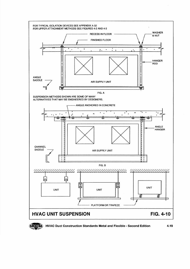
FOR TYPICAL ISOLATION DEVICES SEE APPENDIX A-32
FOR UPPER ATIACHMENT METHODS SEE FIGURES 4-2 AND 4-3
RECESS IN FLOORWASHER\ ; & N U T
rANGL
SADD
I
FINISHED FLOOR
I I
r ~ . ~ . I~ . r~. . .b ' • • •. . ~
I I I I
I
~ ~
I HANGER
I I ROD
I II I
E
I IE
7 AIR SUPPLY UNIT
F .E 1 =
II IV 'ijf'1
FIG. A
SUSPENSION METHODS SHOWN ARE SOME OF MANY
ALTERNATIVES THAT MAY BE ENGINEERED BY DESIGNERS.
ANGLE ANCHORED IN CONCRETE
CHAN
SADD
I \ I
+ . . \ ~ ' .. ~ 6 t > ' . , :~+. . . . .
~ . . t > 6 I>. . . .~ .. . .
I I "T - ItI "T T "T "T "T tt r-"T I IIII
~ ~
ANGLEI
HANGERII
I
IIIII
NEL I
LEI
7I AIR SUPPLY UNITI
[ II
" " I III II I
FIG. B
UNITUNIT UNIT
.-- PLATFORM OR TRAPEZE
HVAC UNIT SUSPENSION FIG. 4-10