SM Series Heat pump - bosch-climate.us · SM Series Heat pump 8-733-942-411 (2016/04) SM024 ......
76
Installation, Operation and Maintenance Manual SM Series Heat pump 8-733-942-411 (2016/04) SM024 | SM036 | SM048 | SMO60 | SM070
Transcript of SM Series Heat pump - bosch-climate.us · SM Series Heat pump 8-733-942-411 (2016/04) SM024 ......

Installation, Operation and Maintenance Manual
SM Series Heat pump
8-73
3-94
2-41
1 (2
016/
04)
SM024 | SM036 | SM048 | SMO60 | SM070

SM Series Heat Pump
SM Series Heat Pump8733942411 (2016/04) Subject to change without prior notice
2 |
CONTENTS
Key to Symbols...................................................................3
Safety Warnings................................................................ 3
Standard package.............................................................. 3
Model Nomenclature.......................................................... 4
General Description........................................................... 5
Moving and Storage........................................................... 6
Initial Inspection ............................................................... 6
Location............................................................................ 6
Configurability .................................................................. 6
Horizontal Configurability .................................................. 6Required Tools ............................................................ 6Instructions - Left-Hand Unit (SM0**-1HZ-*L*-**) ............... 7Instructions - Right-Hand Unit (SM0**-1HZ-*R*-**) ............. 9
Counter-Flow configurability............................................ 11
Vertical Configurability.....................................................11
Return and Discharge Duct Flanges .................................. 11
Pre Installation Unit Preparation ...................................... 12Corner Cap Installation Instructions.............................. 12
Mounting Vertical Units ................................................... 13
Mounting horizontal Units ................................................ 13
Hanging Bracket kit..........................................................14
Condensate Drain............................................................ 15
Duct System.................................................................... 15
Piping ............................................................................. 15
Water Quality Table..........................................................16
Electrical ........................................................................ 17Safety Devices and the UPM Controller ......................... 18ECM Interface Board .................................................. 20Airflow Selector..........................................................21Constant Airflow Motor............................................... 21Dehumidification Method Selector ............................... 21
Options........................................................................... 22Electric Heat ............................................................. 22Heat Recovery Package (HRP) ..................................... 22Valve Relay ............................................................... 23Comfort Alert Module ................................................. 23
Smart Start Assist.............................................................23Mode of Operation .....................................................24Mode of Operation Notes.............................................25
Heat Recovery Package....................................................26Water Tank Preparation ..............................................26HR Water Refill...........................................................26Water Tank Piping ......................................................26
Initial Start-Up .................................................................27
Sequence of Operation.....................................................27Cooling Mode ............................................................27Heating Mode ............................................................27Sequence Of Operation Flow Chart................................28
Application Considerations ..............................................29Well Water Systems....................................................29Cooling Tower/Boiler Systems .....................................29Geothermal Systems ..................................................31
Troubleshooting ..............................................................32
Electronic Thermostat Installation ....................................37
Operating Temperatures and Pressures ............................38
Blower Performance Data HZ Units Rev A ..........................48
Blower Performance Data VT/CF Rev B..............................49
Water Side Pressure Drop Table HZ Units Only Rev A..........50VT/CF Units Rev B.......................................................51
Wiring Diagrams ..............................................................52
Dimensional Drawings......................................................55Horizontal - Straight Through .......................................55Horizontal - Hanging Bracket Location ...........................56Counter Flow.............................................................57CF Vertical ................................................................58
System Checkout..............................................................59
Unit Start-up....................................................................59
Maintenance ...................................................................59
Information On Decommissioning......................................60
Unit Check-Out Sheet.......................................................61Customer Data...........................................................61Unit Nameplate Data...................................................61Operating Conditions..................................................61Auxiliary Heat ............................................................61
Terminology.....................................................................62
Spare Parts List................................................................63Wiring Harness...........................................................63Electrical Box.............................................................68Refrigeration Components...........................................69
Exploded Views................................................................70Refrigeration components...........................................70VT............................................................................71CF............................................................................72HZ............................................................................73

Key to Symbols | 3SM Series Heat Pump
8733942411 (2016/04)Revised 04-16
KEY TO SYMBOLSWarnings
The following keywords are defined and can be used in this document:• NOTICE indicates a situation that could result in
damage to property or equipment.• CAUTION indicates a situation that could result in
minor to medium injury.• WARNING indicates a situation that could result in
sever injury or death.• DANGER indicates a situation that will result in
severe injury or death.Important Information
SAFETY WARNINGS STANDARD PACKAGE
Figure # 1 [1] SM Series Water-to-Air Heat Pump[2] Corner Caps Package (HZ units only)[3] Installation and Operation Manual[4] Hanging Bracket kit (HZ units only)[5] Field Installed Swivel Fittings (VT and CF units only)
Warnings in this document are identified by a warning triangle printed against a grey background. Keywords at the start of the warning indicate the type and seriousness of the ensuing risk if measures to prevent the risk are not taken.
This symbol indicates important information where
there is no risk to property or people.
WARNING: Installation and servicing of this equipment can be hazardous due to system pressure and electrical components. Only trained and qualified personnel should install, repair, or service the equipment.
WARNING: Before performing service or maintenance operations on the system, turn off main power to the unit. Electrical shock could cause personal injury or death.
WARNING: When working on equipment, always observe precautions described in the literature, tags, and labels attached to the unit. Follow all safety codes. Wear safety glasses and work gloves. Use a quenching cloth for brazing, and place a fire extinguisher close to the work area.
NOTICE: To avoid the release of refrigerant into the atmosphere, the refrigerant circuit of this unit must be serviced only by technicians who meet local, state, and federal proficiency requirements.
NOTICE: All refrigerant discharged from this unit must be recovered WITHOUT EXCEPTION. Technicians must follow industry accepted guidelines and all local, state, and federal statutes for the recovery and disposal of refrigerants. If a compressor is removed from this unit, refrigerant circuit oil will remain in the compressor. To avoid leakage of compressor oil, refrigerant lines of the compressor must be sealed after it is removed.
NOTICE: To avoid equipment damage, DO NOT use these units as a source of heating or cooling during the construction process. Doing so may affect the unit’s warranty. The mechanical components and filters will quickly become clogged with construction dirt and debris, which may cause system damage.
5

SM Series Heat Pump
SM Series Heat Pump8733942411 (2016/04) Subject to change without prior notice
4 | Model Nomenclature
MODEL NOMENCLATURE
Figure # 2

General Description | 5SM Series Heat Pump
8733942411 (2016/04)Revised 04-16
GENERAL DESCRIPTIONSM Series Water-to-Air Heat Pumps provide the best combination of performance and efficiency available. All units are performance certified to American Heating and Refrigeration Institute (AHRI) ISO Standard 13256-1. All SM Water-to-Air Heat Pumps conform to UL1995 standard and are certified to CAN/CSA C22.2 No 236 by Intertek-ETL. The Water-to-Air Heat Pumps are designed to operate with entering fluid temperature between 20°F to 80°F in the heating mode and between 30°F to 110°F in the cooling mode for continuous operations.
SM Series Water-to-Air Heat Pumps are available in Vertical (VT), Horizontal (HZ) and Counter-Flow (CF) configurations. HZ units can be field configured from end blow to straight or vice versa using a field installed accessory kit. Several factory installed options are available: Electric Heat, Heat Recovery Package, Smart Start Assist, Auxiliary Pump Relay, and Comfort Alert Module. Electric Heat and Smart Start Assist are also available as field installed accessory. See Pg# 24 for more details.Safety devices are built into each unit to provide the maximum system protection possible when properly installed and maintained. Each unit has an externally mounted LCD status display, allowing unit diagnosis without opening the cabinet.Basic Horizontal unit layout and connections are shown in Figure #3. Refer to Dimensional Drawings for further detail, as well as Vertical and Counter Flow unit details. Pg# 55 through Pg# 58
Figure # 3
[1] LED Unit Diagnostic Display[2] Air handler access panel[3] Condensing section access panel[4] Condensate drain connection[5] Water connection Swivel type (VT/CF-Field, HZ Factory-[6] Heat Recovery water connection (Optional)[7] Heat Recovery disconnect switch (Optional)[8] Electrical connection knockout[9] Electric Heat electrical connection knockout (Optional)[10] Blower outlet (Based on discharged air configuration)
Heat Pump operating under extreme conditions will
have limitations on air/fluid flow rates and/or
temperatures.
Please refer to Bosch SM series ESS for detailed
information on extreme operating conditions.
50° F Minimum Entering Water Temperature (EWT)
is recommended for well water applications with
sufficient water flow to prevent freezing. Antifreeze
solution is required for all closed loop applications
and EWT below 45°F. Cooling Tower/Boiler and
Geothermal applications should have sufficient
antifreeze solution to protect against extreme
conditions and equipment failure. Frozen water coils
are not covered under warranty. Other equivalent
methods of temperature control are acceptable.
1
2
3
4
5
67
9 103
8
10

SM Series Heat Pump
SM Series Heat Pump8733942411 (2016/04) Subject to change without prior notice
6 | Moving and Storage
MOVING AND STORAGEIf the equipment is not needed for immediate installation upon its arrival at the job site, it should be left in its shipping carton and stored in a clean, dry area. Units must only be stored or moved in the normal upright position as indicated by the “UP” arrows on each carton at all times.
INITIAL INSPECTIONPlease inspect the product carefully for any defects or discrepancies.Should you identify any issue, contact the Bosch Wholesaler / Distributor you purchased the unit from.
LOCATIONLocate the unit in an indoor area that allows easy removal of the filter and access panels, and has enough room for service personnel to perform maintenance or repair. Provide sufficient room to make fluid, electrical, and duct connection(s). If the unit is located in a confined space such as a closet, provisions must be made for return air to freely enter the face of unit’s air coil. On horizontal units, allow adequate room below the unit for a condensate drain trap and do not locate the unit above supply piping.Service clearance for SM units up to 6 tons includes the following recommendations. 18” minimum, 24” optimum in front of the blower access panel for access to the blower and blower motor. 24” minimum, 36” optimum in front of the front access panel for access to electrical components, compressor, and service valves.
CONFIGURABILITY
HORIZONTAL CONFIGURABILITYThe Horizontal Configuration water source heat pump is designed to have a field configurable blower orientation: end blow and straight through.An accessory kit is required to made this conversion.
.(Figure#4 and #5)
Figure # 4
Figure # 5
Required Tools• 5/16" hex head driver• 3/8" hex head driver• 7/16" hex head driver• Flat screw driver• Phillips screw driver• 1/4" hex head driver• Needle nose pliers• 5/16”-1/4” ratchet wrench
WARNING: For storage If unit stacking is required, stack units as follows:
Vertical units: Units 6 tons of greater should not be stacked.
Horizontals units: Units 6 tons of greater should not be stacked.
NOTICE: These units are not approved for outdoor installation; therefore, they must be installed inside the structure being conditioned space. Do not locate in areas that are subject to freezing.
NOTICE: Discharge air configuration change is not possible on Heat Pumps equipped with Electric Heat Option.
Part # Straight Through To
End
End To Straight Through
SM024 HZ 8733942424 8733942425
SM036/048 HZ 8733942426 8733942427
SM060/070 HZ 8733942428 8733942429
Left-Hand and Right-hand Horizontal (HZ) units
have different Blower Configuration instructions.
Left- Hand unit instructions refer to Pg#7 and Right-
Hand unit instructions refer to Pg#9.
Internally mounted electric heat is only available in
End Blow configuration.
Blower configuration changes should be done prior
to unit being installed in the final location.

Horizontal Configurability | 7SM Series Heat Pump
8733942411 (2016/04)Revised 04-16
Instructions - Left-Hand Unit (SM0**-1HZ-*L*-**)1. Remove and retain end and side panels.(Figure #6)
Figure # 6 2. Disconnect blower motor wiring and ground wire
fastened to blower housing.(Figure#7)
Figure # 7 3. Remove and retain bracket by removing (3) screws.
(Figure #8)
Figure # 8
4. Loosen blower assembly by removing (4) screws. (Figure #9)
Figure # 9 5. Remove and retain bracket by removing (2) screws.
(Figure #10)
Figure # 10 6. Rotate the blower into its new position.(Figure#11)
Figure # 11

SM Series Heat Pump
SM Series Heat Pump8733942411 (2016/04) Subject to change without prior notice
8 | Horizontal Configurability
7. Remove and retain remaining bracket by removing (2) screws. (Figure #12)
Figure # 12 8. Remove the blower assembly by sliding it forward.
(Figure #13)
Figure # 13 9. Remove and discard blower collar by removing (8)
screws. (Figure #14)
Figure # 14
10. Reorient the blower assembly 180 degree with blower “belly” down and slide back into the cabinet. (Figure #15)
Figure # 15 11. Reinstall bracket in the new vertical position using
(2) screws. (Figure #16)
Figure # 16 12. Reinstall bracket removed in step (#3) using (3)
screws in the same location. (Figure#17)
Figure # 17
Unit top is notched to allow blower to slide through.
1
2
1
2

Horizontal Configurability | 9SM Series Heat Pump
8733942411 (2016/04)Revised 04-16
13. Reinstall remaining bracket using (2) screws. (Figure#18)
Figure # 18 14. Connect vertical and horizontal brackets by
installing (4) screws. (Figure#19)
Figure # 19 15. Reconnect blower motor wiring and ground wire.16. Install the new blower panel from the accessory kit.
Instructions - Right-Hand Unit (SM0**-1HZ-*R*-**)1. Remove and retain end and side panels.(Figure#20)
Figure # 20
2. Disconnect blower motor wiring and ground wire fastened to blower housing.(Figure#21)
Figure # 21 3. Remove and retain (4) screws under the blower
collar. (Figure #22)
Figure # 22
11
22
NOTICE: Air coil is in close proximity to the blower. Air coil fins are easily damaged. Great care must be taken during this step to avoid coil damage. Shipping cardboard can be used as protection during blower removal and installation.

SM Series Heat Pump
SM Series Heat Pump8733942411 (2016/04) Subject to change without prior notice
10 | Horizontal Configurability
4. Slide blower assembly away from mounting bracket. (Figure #23)
Figure # 23 5. Remove and retain (1) vertical bracket by removing
(2) screws. (Figure #24)
Figure # 24 6. Remove and discard horizontal blower bracket by
removing (3) screws. (Figure #25)
Figure # 25
7. Rotate the blower into its new position.(Figure#26)
Figure # 26 8. Remove and retain remaining vertical blower
bracket by removing (2) screws. (Figure #27)
Figure # 27 9. Remove the blower assembly by sliding it forward.
(Figure #28)
Figure # 28
Unit top is notched to allow blower to slide through.

Counter-Flow configurability | 11SM Series Heat Pump
8733942411 (2016/04)Revised 04-16
10. Remove and discard blower collar by removing (8) screws. (Figure #29)
Figure # 29 11. Reorient the blower assembly 180 degree with
blower “belly” up. (Figure #30)
Figure # 30 12. Move the blower back into the cabinet. (Figure #31)
Figure # 31 13. Reinstall (2) vertical blower brackets in the new
horizontal position using (4) screws. (Figure #32)
Figure # 32
14. Secure (2) the new horizontal blower brackets to the unit base using (4) screws. (Figure#33)
Figure # 33 15. Reconnect blower motor wiring and ground wire.16. Install the new blower panel from the accessory kit.
COUNTER-FLOW CONFIGURABILITYThe Counter-Flow Configuration water source heat pump is a dedicated down flow configuration. Available from the factory in Left-hand and right-hand return air configurations.
VERTICAL CONFIGURABILITYThe vertical Configuration water source heatpump is a dedicated up flow configuration.Available from the factory in Left-hand and right handreturn air configurations.
RETURN AND DISCHARGE DUCT FLANGESReturn and discharge opening duct flanges are shipped unfolded. Flange bend lines are perforated allowing easy bending using standard sheet metal pliers or channel locks. (Figure #34)
Figure # 34
Bend flanges one at a time.

SM Series Heat Pump
SM Series Heat Pump8733942411 (2016/04) Subject to change without prior notice
12 | Pre Installation Unit Preparation
PRE INSTALLATION UNIT PREPARATIONCorner Cap Installation InstructionsOnly on HZ UnitsEach corner cap is stamped with one the following identifiers: T, T1,T2 B, B1, B2, A.
1. Identify Letter code on each Corner Cap. (Figure#35)
Figure # 35 2. In preparation for installation identify each Corner
Cap location. (Figure#36)
Figure # 36
3. Remove adhesive backing and install each Corner Cap. (Figure#37 and#38)
Figure # 37
Figure # 38
Corner cap installation is only Applied to HZ units.
VT and CF units do not require corner caps
installation
T1
T1
T2
T2
A
A
A
A
Ensure cabinet surface is clean and free of debris to
ensure proper Corner Cap Adhesion.

Mounting Vertical Units | 13SM Series Heat Pump
8733942411 (2016/04)Revised 04-16
MOUNTING VERTICAL UNITSVertical units should be mounted level on a vibration absorbing pad slightly larger than the base to minimize vibration transmission to the building structure. It is not necessary to anchor the unit to the floor. (Figure #39).
Figure # 39
MOUNTING HORIZONTAL UNITSWhile horizontal units may be installed on any level surface strong enough to hold their weight, they are typically suspended above a ceiling by threaded rods. The manufacturer recommends these be attached to the unit corners by hanging bracket kits. The rods must be securely anchored to the ceiling. Refer to the hanging bracket assembly and installation instructions for details.
Plumbing connected to the heat pump must not come in direct contact with joists, trusses, walls, etc. Some applications require an attic floor installation of the horizontal unit. In this case the unit should be set in a full size secondary drain pan on top of a vibration absorbing mesh. The secondary drain pan prevents possible condensate overflow or water leakage damage to the ceiling. The secondary drain pan is usually placed on a plywood base isolated from the ceiling joists by additional layers of vibration absorbing mesh. In both cases, a 3/4”drain connected to this secondary pan should be run to an eave at a location that will be noticeable.If the unit is located in a crawl space, the bottom of the unit must be at least 4” above grade to prevent flooding of the electrical parts due to heavy rains.
Figure # 40
On VT and CF Units, the condensate drain pan is
internally sloped. There is no internal P-Trap.
NOTICE: Vertical Units should be mounted on a vibration absorbing pad. The unit must be supported along the entirety of its base.
VIBRATION PAD FULL SIZE
WARNING: Horizontal units installed above the ceiling must conform to all local codes. An auxiliary drain pan if required by code, should be at least four inches larger than the bottom of the heat pump.
HZ Units Condensate Drain pan is NOT internally
sloped.
NOTICE: Horizontal (HZ) units must be installed pitched approximately 1/4" towards the condensate drain connection in both directions to facilitate condensate removal. See Figure # 40

SM Series Heat Pump
SM Series Heat Pump8733942411 (2016/04) Subject to change without prior notice
14 | Hanging Bracket Kit
HANGING BRACKET KIT
Installation InstructionsAll horizontal units come with hanging bracket installation kit to facilitate suspended unit mounting using threaded rod.Hanging brackets are to be installed as shown in Figure #41.
Figure # 41 This kit includes the following:(5) Brackets(5) Rubber Vibration isolators(8) Screws #10x1/2 (not used for these models)(10) Bolts 1/4-28x12” Hex bolt
The following are needed and are to be field provided:Threaded rod (3/8“ max dia)Hex nutsWashers (1-3/4“ min O.D.)
1. Remove and discard factory provided screws from locations where hanging brackets will be installed shown in Figure #42
Figure # 42 2. Mount 5 brackets to unit corner post using the Bolts provided in the kit as shown on Figure # 43
Figure # 43
3. Install rubber grommet onto the brackets as shown in Figure # 44
4. Hang the unit and assemble the field provided threaded rod, nuts and washers on to the brackets as shown in Figure # 44
Figure # 44
WARNING: Do not re-use screws removed from the unit on step 1 to mount the hanging brackets to the unit.
WARNING: Follow all applicable codes and requirements when hanging this unit, selecting threaded rod material, etc.
WARNING: Rods must be securely anchored to the ceiling

Condensate Drain | 15SM Series Heat Pump
8733942411 (2016/04)Revised 04-16
CONDENSATE DRAINA drain line must be connected to the heat pump and pitched away from the unit a minimum of 1/8” per foot to allow the condensate to flow away from the unit.This connection must be in conformance with local plumbing codes. A trap must be installed in the condensate line to ensure free condensate flow.A vertical air vent is sometimes required to avoid air pockets. The length of the trap depends on the amount of positive or negative pressure on the drain pan. A second trap must not be included.(Figure # 45)
Figure # 45
DUCT SYSTEMA supply air outlet collar and return air duct flange are provided on all units to facilitate duct connections.
Fold the duct flange outwards along the perforated line. Refer to unit Dimensional Drawings for physical dimensions of the collar and flange. (Pg#55to Pg#58)A flexible connector is recommended for supply and return air duct connections on metal duct systems. All metal ducting should be insulated with a minimum of one inch duct insulation to avoid heat loss or gain and prevent condensate forming during the cooling operation. Application of the unit to uninsulated duct work is not recommended as the unit’s performance will be adversely affected.
The factory provided air filter must be removed when using a filter back return air grill. The factory filter should be left in place on a free return system. If the unit will be installed in a new installation which includes new duct work, the installation should be designed using current ASHRAE procedures for duct sizing. If the unit is to be connected to existing duct work, a check should be made to assure that the duct system has the capacity to handle the air required for the unit application. If the duct system is too small, larger duct work should be installed.Check for existing leaks and repair.
The duct system and all diffusers should be sized to handle the designed air flow quietly. To maximize sound attenuation of the unit blower, the supply and return air plenums should be insulated. There should be no direct straight air path thru the return air grille into the heat pump. The return air inlet to the heat pump must have at least one 90 degree turn away from the space return air grille. If air noise or excessive air flow are a problem, the blower speed can be changed to a lower speed to reduce air flow.
PIPINGSupply and return piping must be as large as the unit connections on the heat pump (larger on long runs).
SM units are supplied with either a copper or optional cupro-nickel condenser. Copper is adequate for ground water that is not high in mineral content.
In conditions anticipating moderate scale formation or in brackish water a cupro-nickel heat exchanger is recommended.Refer to the water quality table on page #16Both the supply and discharge water lines will sweat if subjected to low water temperature. These lines should be insulated to prevent damage from condensation. All manual flow valves used in the system must be ball valves. Globe and gate valves must not be used due to high pressure drop and poor throttling characteristics.
Always check carefully for water leaks and repair appropriately. Units are equipped with swivel female pipe thread fittings. (VT, CF Swivel shipped loose, HZ factory brazed) Consult Unit Dimensional Drawings. (Pg#55 through Pg#58)
Flexible hoses should be used between the unit and the rigid system to avoid possible vibration. Ball valves should be installed in the supply and return lines for unit isolation and unit water flow balancing.
Supply air duct and return air duct flanges are
shipped unfolded with the unit.
NOTICE: Do not connect discharge ducts directly to the blower outlet.
NOTICE: Never use flexible hoses of a smaller inside diameter than that of the fluid connections on the unit.
Proper testing is recommended to assure the well
water quality is suitable for use with water source
equipment. When in doubt, use cupro-nickel.
NOTICE: Never exceed the recommended water flow rates as serious damage or erosion of the water-to-refrigerant heat exchanger could occur.
Teflon tape sealer should be used when connecting
water piping connections to the units to ensure
against leaks and possible heat exchanger fouling.
NOTICE: Do not overtighten the connections.

SM Series Heat Pump
SM Series Heat Pump8733942411 (2016/04) Subject to change without prior notice
16 | Water Quality
WATER QUALITY Table 1: Water Quality
POTENTIAL PROBLEM
Water Characteristic Acceptable Value
Copper Cupro-Nickel
pH (Acidity/Alkalinity) 7-9 7-9
SCALING Hardness (CaCO3, MgCO3) < 350 ppm < 350 ppm
Ryznar Stability Index 6.0 - 7.5 6.0 - 7.5
Langelier Saturation Index -0.5 - +0.5 -0.5 - +0.5
CORROSION Hydrogen Sulfide (H2S) < 0.5 ppm * 10-50 ppm
Sulfates < 125 ppm < 125 ppm
Chlorine < 0.5 ppm < 0.5 ppm
Chlorides < 20 ppm < 150 ppm
Carbon Dioxide < 50 ppm < 50 ppm
Ammonia < 2 ppm < 2 ppm
Ammonia Chloride < 0.5 ppm < 0.5 ppm
Ammonia Nitrate < 0.5 ppm < 0.5 ppm
Ammonia Hydroxide < 0.5 ppm < 0.5 ppm
Ammonia Sulfate < 0.5 ppm < 0.5 ppm
Dissolved Solids < 1,000 ppm < 1,500 ppm
IRON FOULING Iron (Fe2+ Iron Bacteria Potential) < 0.2 ppm < 0.2 ppm
Iron Oxide < 1 ppm < 1 ppm
EROSION Suspended Solids < 10 ppm, < 600 μm size ** < 10 ppm, < 600 μm size **
Maximum Water Velocity 6 ft/sec 6 ft/sec
* No "rotten egg" smell present at < 0.5 ppm H2S.
** Equivalent to 30 mesh strainer

Electrical | 17SM Series Heat Pump
8733942411 (2016/04)Revised 04-16
ELECTRICALRefer to electrical component box layout. (Figure #46)
Properly sized fuses or HACR circuit breakers must be installed for branch circuit protection. See unit nameplate for maximum fuse or breaker size. The unit is provided with a concentric knock-out for attaching common trade sizes of conduit, route power supply wiring through this opening. Always connect the ground lead to the grounding lug provided in the control box and power leads to the line side of compressor contactor as indicated on the wiring diagram Pg#52 through Pg#54).
Figure # 46 Ebox Layout[1] Compressor contactor[2] Comfort Alert Module (Option)[3] Energy Management Relay (Option)[4] UPM[5] Terminal Block [6] Pump Valve Relay[7] Transformer
[8] Capacitor[9] ECM Board[10] Smart Start Assist (Option)[11] Ground Lug
WARNING: Field wiring must comply with local and national electric codes.
WARNING: Power to the unit must be within the operating voltage range indicated on the unit nameplate or on the performance data sheet.
NOTICE: Operation of unit on improper line voltage or with excessive phase imbalance will be hazardous to the unit, constitutes abuse and may void the warranty.
Units supplied with internal electric heat require two
(2) separate power supplies:
1) Unit compressor
2) Electric Heat, blower motor and control circuit.
-------------------------------------------------------------
Refer to the ELECTRIC HEATER PACKAGE
OPTION section and Pg#52 through Pg#54 for
wiring diagrams. See data plate for minimum circuit
ampacities and maximum fuse/breaker sizing.
1 2
3
4
5
6
10
7
8
9
11

SM Series Heat Pump
SM Series Heat Pump8733942411 (2016/04) Subject to change without prior notice
18 | Electrical
Safety Devices and the UPM Controller
Figure # 47 [1] Board Power Indicator[2] UPM Status LED Indicator[3] Water Coil Freeze Protection Temperature Selection [R30][4] Air Coil Freeze Protection Temperature Selection[5] UPM Board Settings[6] Water Coil Freeze Connection (Freeze 1)[7] Air Coil Freeze Connection (Freeze 2)[8] LCD Unit Display Connection[9] 24VAC Power Input[10] Compressor Contact Output[11] High Pressure Switch Connection[12] Call for Compressor Y1[13] Low Pressure Switch Connection[14] 24VAC Power Common[15] Condensate Overflow Sensor[16] Dry Contact/Alarm ALR Contact[17] UPM Ground Standoff
Each unit is factory provided with a Unit ProtectionModule (UPM) that controls the compressor operation and monitors the safety controls that protect the unit.Safety controls include the following:• High pressure switch located in the refrigerant
discharge line and wired across the HPC terminals on the UPM.
• Low pressure switch located in the unit refrigerant suction line and wired across terminals LPC1 and LPC2 on the UPM.
• Water side freeze protection sensor, mounted close to condensing water coil, monitors refrigerant temperature between condensing water coil and thermal expansion valve. If temperature drops below or remains at freeze limit trip for 30 seconds, the controller will shut down the compressor and enter into a soft lockout condition. The default freeze limit trip is 26°F, however this can be changed to 15°F by cutting the R30 or Freeze1 resistor located on top of DIP switch SW1 (Refer to Figure #47, item [3] for resistor location), Refer to Figure #48 for sensor location.
Figure # 48
If the unit is being connected to a thermostat with a
malfunction light, this connection is made at the unit
ALR Contact. Refer to Figure #47
If the thermostat is provided with a malfunction light
powered off of the common (C) side of the
transformer, a jumper between “R” and “COM”
terminal of “ALR” contacts must be made.
If the thermostat is provided with a malfunction light
powered off of the hot (R) side of the transformer,
then the thermostat malfunction light connection
should be connected directly to the (ALR) contact on
the unit’s UPM board.
1
2
3
4
5
6 7 9 10
111213
17
1415 168
UPM Board Dry Contacts are Normally Open (NO)
NOTICE: If unit is employing a fresh water system (no anti-freeze protection), it is extremely important to have the Freeze1 R30 resistor set to 26°F in order to shut down the unit at the appropriate leaving water temperature and protect your heat pump from freezing.
Electrical | 19SM Series Heat Pump
8733942411 (2016/04)Revised 04-16
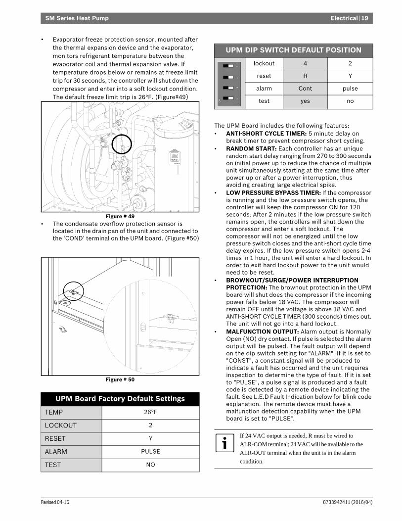
• Evaporator freeze protection sensor, mounted after the thermal expansion device and the evaporator, monitors refrigerant temperature between the evaporator coil and thermal expansion valve. If temperature drops below or remains at freeze limit trip for 30 seconds, the controller will shut down the compressor and enter into a soft lockout condition. The default freeze limit trip is 26°F. (Figure#49)
Figure # 49 • The condensate overflow protection sensor is
located in the drain pan of the unit and connected to the ‘COND’ terminal on the UPM board. (Figure #50)
Figure # 50
The UPM Board includes the following features:• ANTI-SHORT CYCLE TIMER: 5 minute delay on
break timer to prevent compressor short cycling.• RANDOM START: Each controller has an unique
random start delay ranging from 270 to 300 seconds on initial power up to reduce the chance of multiple unit simultaneously starting at the same time after power up or after a power interruption, thus avoiding creating large electrical spike.
• LOW PRESSURE BYPASS TIMER: If the compressor is running and the low pressure switch opens, the controller will keep the compressor ON for 120 seconds. After 2 minutes if the low pressure switch remains open, the controllers will shut down the compressor and enter a soft lockout. The compressor will not be energized until the low pressure switch closes and the anti-short cycle time delay expires. If the low pressure switch opens 2-4 times in 1 hour, the unit will enter a hard lockout. In order to exit hard lockout power to the unit would need to be reset.
• BROWNOUT/SURGE/POWER INTERRUPTION PROTECTION: The brownout protection in the UPM board will shut does the compressor if the incoming power falls below 18 VAC. The compressor will remain OFF until the voltage is above 18 VAC and ANTI-SHORT CYCLE TIMER (300 seconds) times out. The unit will not go into a hard lockout.
• MALFUNCTION OUTPUT: Alarm output is Normally Open (NO) dry contact. If pulse is selected the alarm output will be pulsed. The fault output will depend on the dip switch setting for "ALARM". If it is set to "CONST", a constant signal will be produced to indicate a fault has occurred and the unit requires inspection to determine the type of fault. If it is set to "PULSE", a pulse signal is produced and a fault code is detected by a remote device indicating the fault. See L.E.D Fault Indication below for blink code explanation. The remote device must have a malfunction detection capability when the UPM board is set to "PULSE".
UPM Board Factory Default Settings
TEMP 26°F
LOCKOUT 2
RESET Y
ALARM PULSE
TEST NO
UPM DIP SWITCH DEFAULT POSITION
lockout 4 2
reset R Y
alarm Cont pulse
test yes no
If 24 VAC output is needed, R must be wired to
ALR-COM terminal; 24 VAC will be available to the
ALR-OUT terminal when the unit is in the alarm
condition.

SM Series Heat Pump
SM Series Heat Pump8733942411 (2016/04) Subject to change without prior notice
20 | ECM INTERFACE BOARD
• DISPLAY OUTPUT: The Display output is a pulse output connected to the Unit Diagnostic Display (UDD) and it pulses 24VAC when the unit is in an lockout alarm condition.
• TEST DIP SWITCH: A test dip switch is provided to reduce all time delays settings to 10 seconds during troubleshooting or verification of unit operation.
• FREEZE SENSOR: The default setting for the freeze limit trip is 26°F (sensor number 1); however this can be changed to 15°F by cutting the R30 resistor located on top of the DIP switch SW1. The default setting for the freeze limit trip is 26°F (sensor number 1); however this can be changed to 15°F by cutting the R24 resistor located on top of the DIP switch SW1. Since freeze sensor 2 is dedicated to monitor the evaporator coil it is recommended to leave the factory default setting on the board. The UPM controller will constantly monitor the refrigerant temperature with the sensor mounted close to the condensing water coil between the thermal expansion valve and water coil. If temperature drops below or remains at the freeze limit trip for 30 seconds, the controller will shut the compressor down and enter into a soft lockout condition. Both the status LED and the Alarm contact will be active. The LED will flash (three (3) times) the code associated with this alarm condition. If this alarm occurs 2 times (or 4 if Dip switch is set to 4) within an hour the UPM controller will enter into a hard lockout condition. Sensor number 2 will constantly monitor the refrigerant temperature with the sensor mounted close to the evaporator between the thermal expansion valve and evaporator coil as shown in Figure #48. If temperature drops below or remains at the freeze limit trip for 30 seconds, the controller will shut the compressor down and enter into a soft lockout condition. Both the status LED and the Alarm contact will be active. The LED will flash (six (6) times) the code associated with this alarm condition. If this alarm occurs 2 times (or 4 if Dip switch is set to 4) within an hour the controller will enter into a hard lockout condition.
• INTELLIGENT RESET: If a fault condition is initiated, the 5 minute delay on break time period is initiated and the unit will restart after these delays expire. During this period the fault LED will indicate the cause of the fault. If the fault condition still exists or occurs 2 or 4 times (depending on 2 or 4 setting for Lockout dip switch) before 60 minutes, the unit will go into a hard lockout and requires a manual lockout reset. A single condensate overflow fault will cause the unit to go into a hard lockout immediately, and will require a manual lockout reset.
• LOCKOUT RESET: A hard lockout can be reset by turning the unit thermostat off and then back on when the “RESET” dip switch is set to “Y” or by shutting off unit power at the circuit breaker when the “RESET” dip switch is set to “R”.
ECM INTERFACE BOARDRefer to Figure #46, item [9] for ECM interface board location. In addition to providing a connecting point for thermostat wiring, the interface board also translates thermostat inputs into control commands for the Electronic Commutated Motor (ECM) DC fan motor and provides thermostat signals to the unit’s UPM board. The thermostat connections and their functions are as follows:
Figure # 51 [1] Motor harness plug[2] Blower CFM adjustment[3] Motor settings[4] Dehumidification indication[5] Thermostat contact inputs[6] CFM count indicator[7] Thermostat input status indication[8] Reheat digital outputs[9] Thermostat outputs[10] 24 VAC[11] Dehumidification method selector
NOTICE: Operation of unit in test mode can lead to accelerated wear and premature failure of components. The "TEST" switch must be set back to "NO" after troubleshooting/servicing.
NOTICE: Freeze sensor will not guard against the loss of water. Flow switch is recommended to prevent unit from running if water flow is lost or reduced.
The blower motor will remain active during a lockout
condition.
10 1
2789 5 1146
3

ECM INTERFACE BOARD | 21SM Series Heat Pump
8733942411 (2016/04)Revised 04-16
• CFM count indicator (Figure #51 item [6]) blinks to indicate approximate airflow in CFM and may flicker when the unit is off.
• Each blink of the LED represent approximately 100 CFM of air delivery so if the LED blinks 12 times, pauses, blinks 12 times, etc. the blower is delivering approximately 1200 CFM.
Constant Airflow MotorThe Constant Airflow Motor is an Electronic Commutated Motor (ECM) that provides a constant air flow over a wide range of external static pressures, while optimizing the power consumption of the motor.This option allows the unit to have different air flow settings depending on the mode that the unit is operating; i.e heating, cooling, fan only, electric heat, etc. Refer to the ECM Interface Board section (pg.20) for more information.
Airflow SelectorThe airflow selector (Figure #50, items [2] & [3]) allows airflow adjustment to meet application requirements and to ease troubleshooting.
• CFM Selector (Figure #51, Item [2]) must remain with only “A” being enabled.
• ADJUST Selector can be adjusted to NOM, (+), (-), or TEST. NOM, (+) and (-) can be adjusted as needed by application. TEST is used for troubleshooting to override unit airflow to 100%
Figure # 52
Dehumidification Method SelectorDehumidification method selector (Figure #51, item [11]) must be set to NO for cool to dehumidify method as below.:• On dehumidification call, the heat pump fan will
operate at a lower speed to increase dehumidification while cooling. Dehumidification selector ((Figure #51), item [11]) should be selected to ‘NO’.
Dehumidification indicator LED (Figure #51, item [4]) will energize when dehumidification call is present.
Figure # 53
CFM LED indication is an approximation. Utilize
conventional Test and Balance equipment for
accurate airflow measurement.
Thermostat Outputs
Y1 First Stage Compressor Operation
Y2 Second Stage Compressor Operation
G Fan
O Reversing Valve (energized in cooling)
W1 Auxiliary Electric Heat (runs in conjunction with compressor)
EM/W2 Emergency Heat (electric heat only)
C Transformer 24 VAC Common
R Transformer 24 VAC Hot
H Dehumidification Mode
Only one dip switch can be enabled at a time. Refer
to Figure #52 for each airflow setting.
CAUTION: Do not set the ADJ DIP switch to the (-) setting when electric heaters are installed. Doing so may cause the heaters to cycle on their thermal overload switches, potentially shortening the life of the switches.
DANGER: Always disconnect power before changing DIP switch positions on the interface board and reset the unit afterward.
In this mode, the heat pump will only dehumidify the
space when it is running in cooling mode.

SM Series Heat Pump
SM Series Heat Pump8733942411 (2016/04) Subject to change without prior notice
22 | Options
OPTIONSNumber of factory installed options are available on SM Series of Heat Pumps. The following details the purpose, function and components of each option.
Electric HeatInternally mounted supplemental electric heat is available on select models of the SM series. Electric heating elements can operate along with reverse cycle heating as auxiliary heat or in lieu of mechanical heating (refrigeration heating) as emergency backup heat.Availability matrix, including available nominal kW capacities is shown below:
Heat Recovery Package (HRP)The heat recovery package is a factory installed option on SM series of heat pumps. The HRP can be used to heat potable water during unit operation using waste heat from the compressor discharge gas. In some cases the HRP can provide most or all of the hot water requirements for a typical home.The HRP consists of three major components:• double wall, vented refrigerant to water heat
exchanger• circulating pump• control circuitThe heat exchanger is rated for use with potable water and is acceptable for use as a domestic water heating device in most building codes. The pump circulates water between the domestic hot water tank and HRP heat exchanger in the Heat Pump. The control circuit ensures that the HRP only operates when there is available heat from the compressor and when the water is within a safe temperature range of below 140 deg F.
When the heat pump compressor operates, the HRP will monitor the temperature of the discharge gas from the compressor. Once discharge gas is hot enough to provide useful heat to the domestic water tank, the circulating pump will be enabled, drawing water from the tank, through the HRP heat exchanger and then depositing the heated water back into the tank. If the water temperature reaches 140 deg F, the circulating pump is disabled to prevent over heating of the domestic water. The HRP is provided with an on/off switch in case the end user desires that the HRP be inactivated (typically during the winter months when space heating is most important).
Internal mounted Electric Heat is only available on
top blow vertical cabinets, end blow horizontal
cabinet or on down blow counterflow cabinets.
In cases where Electric Heat is not available in a
desired configuration but is needed, contact your
distributor for available Duct Mounted Electric Heat
Package.
NOTICE: Units with internal electric heat must
have 2 field power supplies.
Heater Model
KW Stgs Btu/h Product Series Compatibility
208V 230V 208V 230V SM024 SM036 SM048 SM060 SM070
HK050-1201 3.6 4.8 1 12300 16300 x x x x x
HK100-1201 7.2 9.6 2 24600 32700 x x x x x
HK150-1201 10.8 14.4 2 36900 49100 x x x x
HK200-1201 14.4 19.2 2 49200 63400 x x x
x Available
NOTICE: If heat recovery unit is installed in an area where freezing may occur, the unit must be drained during winter months to prevent heat exchanger damage. Heat exchanger ruptures that occur due to freezing will void the heat recovery package warranty along with the heat pump warranty.

Smart Start Assist | 23SM Series Heat Pump
8733942411 (2016/04)Revised 04-16
Valve RelayThe factory installed pump relay can be used to energize a supply pump or solenoid valve when there is a call for compressor operation. This relay can be used to switch either high or low voltage power.
Comfort Alert ModuleThe Comfort Alert diagnostics module (CADM) is a breakthrough innovation for troubleshooting heat pump system failures. (Figure #54)
Figure # 54 By monitoring and analyzing data from the compressor and the thermostat demand, the module can accurately detect the cause of electrical and system related failures without any sensors. A flashing LED indicator communicates the ALERT code and guides the service technician more quickly and accurately to the root cause of a problem.
When an abnormal system condition occurs, the Comfort Alert module displays the appropriate ALERTand/or TRIP LED.The yellow ALERT LED will flash a number of times consecutively, pause and then repeat the process.To identify a Flash Code number, count the number of consecutive flashes.Every time the module powers up, the last ALERT Flash Code that occurred prior to shut down is displayed for one minute.
SMART START ASSISTSM series are available with the Smart Start Assist device as either a factory installed option or a field installed accessory.This device reduces starting (in-rush) current for compressors by 45% to 65%. This reduction in starting current can eliminate or greatly reduce “light flickering” during compressor starts and can reduce the required size of back-up transformers. the adaptive technology of the device can also extend compressor life by providing smoother, lower currents starts and by protecting the compressor from transient over voltage and under voltage after ramp up.
The Smart Start is designed for single phase scroll compressors and can also optimize algorithms for high pressure starts. SSA as showed in figure #55.
Figure # 55
SSA Specifications
This module does not provide safety protection! The
Comfort Alert module is a monitoring device and
cannot shut down the compressor directly.
Rated Operational Voltage: 208/230VACrms +/- 15% 50-60 Hz
Environmental Operating Range:
-4° to 149°F (-20° to 65°C); < 95% @ 40 C relative humidity, non-con-densing
Degree of Protection: IP20
Overvoltage: Category II
Operational Rated Current: 32 Amps
Max Starting Current:
Min Full Load Current:
80A ACrms
80A ACrms
Min time between starts: 6 minutes
Min time between stop to start:
3 minutes
Smart Start Assist
Mounting Plate

SM Series Heat Pump
SM Series Heat Pump8733942411 (2016/04) Subject to change without prior notice
24 | Smart Start Assist
Mode of Operation
Figure # 56
Figure # 57

Smart Start Assist | 25SM Series Heat Pump
8733942411 (2016/04)Revised 04-16
Mode of operation Notes1. The Smart Start Assist has 2 indication LEDs on
board. The green LED indicates the status of the on-board power supply while the red LED indicates an alarm condition or the recovery time between starts.
2. Once the main voltage is present, the green LED will be fully ON. In case the main voltage is less than the stated pickup voltage alarm value, the green LED will be flashing. In case main voltage is higher than the stated pick-up voltage and green LED is flashing, then this may indicate that the on-board power supply is faulty. (Power Supply Alarm)
3. Upon closing K1, the Smart Start Assist will start ramping, duration of which is < 1 second, provided that the minimum time from stop to start is respected. When opening K1, the Smart Start Assist will stop without any ramp down.
4. In the case of an under voltage, the Smart Start Assist will shut down and the red LED flashes 2 times as long as the under voltage is present. Once the main voltage is restored the red LED will continue flashing for 5 minutes.Following these 5 minutes (6 minutes for HP versions), the Smart Start Assist will start ramping function in the case K1 is closed. The device can be reset at any time by removing power on L1-N connection. When the power is reapplied, the soft starter will star ramping up as soon as K1 is closed, provided that the minimum time from stop to start are respected.
5. If an over current (>80A for 1 sec.) is sensed, the Smart start Assist will shut down and the red LED will flash 3 times indicating an over current situacion.This continues for 5 minutes. In the case that the over current is still present at the second attempt, user intervention is required to reset the controller by cycling power for the device to operate again as this implies that there are problems in the system.
6. A detection circuitry provides protection in case of a faulty starting capacitor EMR. In such situation, the red LED will flash 4 times for 5 minutes. Smart Start Assist will check the status of the starting capacitor EMR before attempting a ramping function (in the case K1 is closed). If at the second attempt, the starting capacitor EMR is found to be faulty, user intervention is required to reset the controller by cycling power for the device.
7. In the case of incomplete ramping of the Smart Start Assist, the red LED will flash 5 times. The flashing will be indicated by the red LED for 5 minutes. If after the second attempt, there is another incomplete ramp alarm, user intervention is required to reset the controller.
8. During the recovery from under-voltage, over-current and incomplete ramp alarms, the red LED will flash twice the normal flashing frequency using the same number of flashes. The figure #108 shows the flashing in case of a recovery from an under-voltage alarm.
9. During the recovery time between starts, the Smart Start Assist will be continuously ON until the necessary recovery time elapses.
10. If Power supply on Smart Start Assist is removed before the recovery period has elapsed, when supply is restored, the delay will continue until the remaining recovery time from the last start/stop (before supply removal) is over. Following this, another start may be attempted. If supply is removed during alarm recovery (red LED flashing), when supply is restored, the alarm will be reset and the Smart Start Assist will only wait for the respective delays between starts and/or stop to start to elapse before attempting another start (assuming K1 is closed).

SM Series Heat Pump
SM Series Heat Pump8733942411 (2016/04) Subject to change without prior notice
26 | Heat Recovery Package
HEAT RECOVERY PACKAGEWater Tank Preparation1. Turn off electrical or fuel supply to the water heater.2. Attach garden hose to water tank drain connection
and run other end of hose out doors or to an open drain.
3. Close cold water inlet valve to water heater tank.4. Drain tank by opening drain valve on the bottom of
the tank, then open pressure relief valve or hot water faucet.
5. Once drained the tank should be flushed with cold water until the water leaving the drain hose is clear and free of sediment.
6. Close all valves and remove the drain hose.7. Install HR water piping.
HR Water PipingAll hot water piping MUST be a minimum of 3/8” O.D. copper tube to a maximum distance of 15 feet. For distances beyond fifteen feet but not exceeding 60 feet use 1/2” copper tube. Separately insulate all exposed surface of both connecting water lines with 3/8” wall closed cell insulation. Install isolation valves on supply and return to the heat recovery. (Figure #58)
Figure # 58
Water Tank Refill1. Open the cold water supply to the tank.2. Open a hot water faucet to vent air from the system
until water flows from the faucet, then close.3. Depress the hot water tank pressure relief valve
handle to ensure there is no air remaining in the tank.
4. Carefully inspect all plumbing for water leaks. Correct as required.
5. Purge all air from HR through an external purge valve. Allow all air to bleed out until water appears at the valve. Locate the external purge value at the highest point in installation.
6. Before restoring the power or fuel supply to the water heater, adjust the temperature setting on the tank thermostat(s) to ensure maximum utilization of the heat available from the refrigeration system and conserve the most energy. On tanks with both upper and lower elements and thermostats, the lower element should be turned down to 100° F, while the upper element should be adjusted to 120° F. Depending upon the specific needs of the customer, you may need to adjust the upper element differently. On tanks with a single thermostat lower the thermostat setting to 120° F or the “LOW” position. After thermostat adjustments are completed, replace access cover and restore electrical or fuel supply to water heater.
Concentric water fitting (p/n 8-733-907-779) is
recommended.
NOTE: Diagram for illustration purposes only.
Isolation
valves
NOTICE: All piping from HRP to domestic water tank must be copper.

Initial Start-Up | 27SM Series Heat Pump
8733942411 (2016/04)Revised 04-16
INITIAL START-UP
1. Turn on the heat pump. The HR pump should not run if the compressor is not running.
2. Turn HR switch to the “ON” position. The pump will operate if entering water temperature to HR is below 120° F.
3. The temperature difference between the water entering and leaving the heat recovery should be 5° to 15° F.
4. Allow the unit to operate for 20 to 30 minutes to ensure it is functioning properly. The pump should shut off when the water temperature entering the heat recovery reaches 120°F.
SEQUENCE OF OPERATIONCooling ModeEnergizing the “O” terminal energizes the unit reversing valve thus placing the unit into cooling mode. The fan motor starts when the “G” terminal is energized.
When the thermostat calls for first stage cooling (Y1) the loop pump or solenoid valve if present is energized and the first stage of compressor capacity starts. The fan ramps up to first stage cooling air flow in 30 seconds.
When the thermostat calls for second stage cooling (Y2) the second stage (or full compressor capacity) is initiated. The fan ramps up to full cooling air flow.
Once the thermostat is satisfied, the compressor shuts down and the fan ramps down to either fan only mode or off over a span of 30 seconds.
Heating ModeThe first two stages of heating (Y1 & Y2) operate in the same manner as cooling, but with the reversing valve de-energized. On a call for auxiliary heat (W1), the fan ramps up to auxiliary heat air flow immediately and the electric heater package is energized along with the compressor.
As the thermostat is satisfied, the heaters will shut off as soon as W1 is de-energized, and the compressors will remain on until the thermostat stages are satisfied.
Once the thermostat is satisfied, the compressor shuts down and the fan ramps down either fan only mode or off over a span of 30 seconds. If thermostat has two different output points one for Auxiliary heat and a different one for Emergency heat the two outputs must be terminated on W1 units equipped with one stage of Electric heat.
NOTICE: Make sure all valves in heat recovery water piping system are open. NEVER OPERATE HR PUMP DRY.
The fan motor will take 30 seconds to ramp up to
operating speed and will run at fan only rated air flow
as long as there is no call for compressor or heater
operation.
Some options will have a built in delay, and hence,
compressor operation is not immediate. See
‘Options’ sections for more detail.
Note that a fault condition initiating a lockout will
de-energize the compressor irrespective of which
stage is engaged.
If the unit compressor locks out for any reason at this
time, the electric heaters will continue to function
normally.
When using a 2-cool, 3-heat thermostat both the W1
& W2 on the Heat Pump and W2 & EM on the
thermostat must be connected together via a jumper.
(See Figure#64)

SM Series Heat Pump
SM Series Heat Pump8733942411 (2016/04) Subject to change without prior notice
28 | Sequence of Operation
Sequence Of Operation Flow Chart
Figure # 59
CC
LOCKOUT CAN BE SET TO 4 VIA DIP SWITCH
BLINK CODE ON STATUS LEDSOFT LOCKOUTRECORD ALARM
START COUNTER (IF APPLICABLE)
CC OUTPUT = ON
NO
YES
LPC =CLOSED
FRZ >TEMP LIMIT
Y1 = ON
TIME > 30 SEC
CON > 0
POWER/ SWITCHES/SENSOR STATUS CHECK
STARTTIMER
NOYES
NO
YES
NO
YES
T > ASC OR RS SEC
YES
NO
NO
YES
STARTANTI SHORT CYCLE
INITIAL POWER UP
YES
NO
STARTRANDOM START UP
START
COUNTER NEEDED?
YES
COUNT = 2 OR
COUNT = 4
BLINK CODE ON STATUS LEDDISPLAY OUTPUT = PULSEALR OUTPUT = ON/PULSE
NO
YES
HARD LOCKOUT?
CC OUTPUT = OFF
V > 18VACNO
YES YES
NO
BLINK CODE ON STATUS LED
NO
RESET ON Y
CLEAR FAULTS
R = 24VACNO
YES NO
YES
NO
YES
HPC = CLOSED
RESET ON R
CC OUPUT= ON
NO
YES
TIME > 120 SEC
STARTTIMER
NO
YES
CNT = CNT+1

Application Considerations | 29SM Series Heat Pump
8733942411 (2016/04)Revised 04-16
APPLICATION CONSIDERATIONSWell Water SystemsCopper is adequate for ground water that is not high in mineral content. Should your well driller express concern regarding the quality of the well water available or should any known hazards exist in your area, we recommend proper testing to assure the well water quality is suitable for use with water source equipment. (See Water Quality table on page #16) In conditions anticipating moderate scale formation or in brackish water a cupro-nickel heat exchanger is recommended. In well water applications water pressure must always be
maintained in the heat exchanger. This can be accomplished with either control valve or a bladder type expansion tank. When using a single water well to supply both domestic water and the heat pump care must be taken to ensure that the well can provide sufficient flow for both. In well water applications a slow closing solenoid valve must be used to prevent water hammer. Solenoid valves should be connected across Y1 and C1 on the interface board for all. Make sure that the VA draw of the valve does not exceed the contact rating of the thermostat.(Figure #51)
Figure # 60 Example System Set-up[1] Flex Duct Connection[2] Low Voltage Control Connection[3] Vibration Pad[4] Ball Valves[5] Solenoid Valve Slow Closing[6] Condensate Drain Connection[7] Drain Valves[8] Hose Kits (optional) [9] Pressure Tank (optional) [10] P/T Ports (optional)[11] Line Voltage Connection [12] Electric Heater Line Voltage Disconnect [13] Unit Line Voltage Disconnect
Cooling Tower/Boiler SystemsThe cooling tower and boiler water loop temperature is usually maintained between 50° F to 100 ° F to assure adequate cooling and heating performance.In the cooling mode, heat is rejected from the unit into the water loop. A cooling tower provides evaporative cooling to the loop water thus maintaining a constant supply temperature to the unit. When utilizing open cooling towers, chemical water treatment is mandatory to ensure the water is free from corrosive elements. A secondary heat exchanger (plate frame) between the unit and the open cooling tower may also be used. It is imperative that all air be eliminated from the closed loop side of the heat exchanger to ensure against fouling. In the heating mode, heat is absorbed from the water loop. A boiler can be utilized to maintain the loop at thedesired temperature.
1
2
3
4
5
6
7 Typical Installation shown for illustration purposes only.
9
8
10
11
12
13
(Not actual product)

SM Series Heat Pump
SM Series Heat Pump8733942411 (2016/04) Subject to change without prior notice
30 | Application Considerations
Consult the specification sheets for piping sizes.Do not overtighten the connections. Flexible hoses should be used between the unit and the rigid system to avoid possible vibration.
Ball valves should be installed in the supply and return lines for unit isolation and unit water flow balancing. Pressure/temperature ports are recommended in both supply and return lines for system flow balancing. Water flow can be accurately set by measuring the water-to-refrigerant heat exchangers water side pressure drop. See specification sheets for water flow vs. pressure drop information.No unit should be connected to the supply or return piping until the water system has been completely cleaned and flushed to remove any dirt, piping chips or other foreign material. Supply and return hoses should be connected together during this process to ensure the entire system is properly flushed. After the cleaning and flushing has taken place the unit may be connected to the water loop and should have all valves wide open. (Figure #61)
Figure # 61 [1] Line voltage disconnect (unit)[2] Low voltage control connection[3] P/T ports (optional)[4] Hose kits (optional)[5] Ball valves[6] Supply and return line of central system[7] Flex duct connection[8] Hanging bracket assembly[9] Threaded rod[10] Hanging bracket assembly
NOTICE: Water piping exposed to extreme low ambient temperatures is subject to freezing.
Teflon tape sealer should be used when connecting to
the unit to ensure against leaks and possible heat
exchanger fouling.
Diagram shows typicalinstallation and is for illustration purposes only. Ensure access to HeatPump is not restricted.

Application Considerations | 31SM Series Heat Pump
8733942411 (2016/04)Revised 04-16
Geothermal SystemsClosed loop and pond applications require specialized design knowledge. No attempt at these installations should be made unless the dealer has received specialized training. Utilizing a Bosch flow center, hose kit, and connection accessories will simplify the installation process. Anti-freeze solutions are utilized when low evaporating conditions are expected to occur. Refer to the Bosch flow center installation manuals for more specific instructions. (Figure #61)
Figure # 62 [1] Line voltage disconnect (unit)[2] Flex duct Connection[3] Low voltage control connection[4] Line voltage connection (unit)[5] P/T ports[6] Vibration pad[7] Condensate drain connection[8] Ground loop connection kit[9] Ground loop pumping package[10] Polyethylene with insulation[11] Line voltage disconnect (electric heater)
Diagram shows typicalinstallation and is for illustration purposes only. Ensure access to Heat Pump is not restricted.

SM Series Heat Pump
SM Series Heat Pump8733942411 (2016/04) Subject to change without prior notice
32 | Troubleshooting
TROUBLESHOOTINGSM Series Water Source Heat Pump is equipped with a externally mounted LCD screen that displays unit errors. (Figure #63)
Figure # 63
Troubleshooting Information Solution column may
reflect a possible fault that may be one of, or a
combination of causes and solutions. Check each
cause and adopt “process of elimination” and or
verification of each before making any conclusion.
UPM Board LED Indications
Indication Color Blinks Description
GREEN Solid 18-30 VAC Power is present
RED 1 High pressure lockout
RED 2 Low pressure lockout
RED 3 Coax Freeze sensor lockout
RED 4 Condensate overflow
RED 5 Brownout
RED 6 Evaporator Freeze lockout
Unit Troubleshooting
Problem Possible Cause Checks and Correction
ENTIRE UNIT DOES NOT RUN
Power Supply Off Apply power, close disconnect
Blown Fuse Replace fuse or reset circuit breaker. Check for correct fuses
Voltage Supply Low
If voltage is below minimum voltage specified on unit data plate, contact local power company.
Thermostat Set the fan to “ON”, the fan should run. Set thermostat to “COOL” and lowest temperature setting, the unit should run in the cooling mode (reversing valve energized). Set unit to “HEAT” and the highest temperature setting, the unit should run in the heating mode. If neither the blower or compressor run in all three cases, the thermostat could be miswired or faulty. To ensure miswired or faulty thermostat verify 24 volts is available on the condensing section low voltage terminal strip between “R” and “C”, “Y” and “C”, and “O” and “C”. If the blower does not operate, verify 24 volts between terminals “G” and “C” in the air handler. Replace the thermostat if defective.
BLOWER OPERATES BUT COMPRESSOR DOES NOT
Thermostat Check setting, calibration, and wiring
Wiring Check for loose or broken wires at compressor, capacitor, or contactor.
Safety Controls Check UPM board red default L.E.D. for Blink Code
Compressor overload open
If the compressor is cool and the overload will not reset, replace compressor.
Compressor motor grounded
Internal winding grounded to the compressor shell. Replace compressor. If compressor burnout, install suction filter dryer.
Compressor windings Open
After compressor has cooled, check continuity of the compressor windings. If the windings are open, replace the compressor

Troubleshooting | 33SM Series Heat Pump
8733942411 (2016/04)Revised 04-16
UNIT OFF ON HIGH PRESSURE CONTROL
Discharge pressure too high
In “COOLING” mode: Lack of or inadequate water flow. Entering water temperature is too warm. Scaled or plugged condenser. In “HEATING” mode: Lack of or inadequate air flow. Blower inoperative, clogged filter or restrictions in duct work
Refrigerant charge
The unit is overcharged with refrigerant. Reclaim refrigerant, evacuate and recharge with factor recommended charge.
High pressure Check for defective or improperly calibrated high pressure switch.
UNIT OFF ON LOW PRESSURE CONTROL
Suction pressure too low
In “COOLING” mode: Lack of or inadequate air flow. Entering air temperature is too cold. Blower inoperative, clogged filter or restrictions in duct work. In “HEATING” mode: Lack of or inadequate water flow. Entering water temperature is too cold. Scaled or plugged condenser.
Refrigerant charge
The unit is low on refrigerant. Check for refrigerant leak, repair, evacuate and recharge with factory recommended charge.
Low pressure switch
Check for defective or improperly calibrated low pressure switch.
UNIT SHORT CYCLES
Unit oversized Recalculate heating and or cooling loads.
Thermostat Thermostat installed near a supply air grill; relocate thermostat. Readjust heat anticipator.
Wiring and controls
Check for defective or improperly calibrated low pressure switch.
INSUFFICIENT COOLING OR HEATING
Unit undersized Recalculate heating and or cooling loads. If excessive, possibly adding insulation and shading will rectify the problem
Loss of conditioned air by leakage
Check for leaks in duct work or introduction of ambient air through doors or windows
Airflow Lack of adequate air flow or improper distribution of air. Replace dirty filter
Refrigerant charge
Low on refrigerant charge causing inefficient operation
Compressor Check for defective compressor. If discharge is too low and suction pressure is too high, compressor is not pumping properly. Replace compressor.
Reversing Valve Defective reversing valve creating bypass of refrigerant from discharge of suction side of compressor. Replace reversing valve
Operating pressures
Compare unit operation pressures to the pressure/temperature chart for the unit.
TXV Check TXV for possible restriction or defect. Replace if necessary.
Moisture, noncondensables
The refrigerant system may be contaminated with moisture or noncondensables. Reclaim refrigerant, replace filter dryer, evacuate the refrigerant system, and recharge with factory recommended charge.
Unit Troubleshooting
Problem Possible Cause Checks and Correction

SM Series Heat Pump
SM Series Heat Pump8733942411 (2016/04) Subject to change without prior notice
34 | Troubleshooting
Compressor Ohms
Model Start Winding Run Winding
SM024 1.64 1.3
SM036 1.52 0.88
SM048 1.86 0.52
SM060 1.63 0.39
SM070 1.85 0.34
Tolerance +/- 7%. All resistance values must be measured with compressor at room temperature.
Comfort Alert Module -Flash Codes
Status LEDStatus LED Description Status LED Troubleshooting Information Solution
YELLOW "ALERT" FLASH CODE 3
Short Cycling Compressor is running only briefly
1. Thermostat demand signal is intermittent 2. Time delay relay or control board defective3. If high pressure switch present go to Flash Code 2 information4. If low pressure switch present go to Flash Code 1 information
YELLOW "ALERT" FLASH CODE 4
Locked Rotor 1. Run capacitor has failed (may not be bad, verify) 2. Low line voltage (contact utility if voltage at disconnect is low)
• Check wiring connections 3. Excessive liquid refrigerant in compressor4. Compressor bearings are seized
• Measure compressor oil level
YELLOW "ALERT” FLASH CODE 5
Open Circuit 1. Outdoor unit power disconnect is open 2. Compressor circuit breaker or fuse(s) is open 3. Compressor contactor has failed open
• Check compressor contactor wiring and connectors • Check for compressor contactor failure (burned, pitted or
open) • Check wiring and connectors between supply and
compressor • Check for low pilot voltage at compressor contactor coil
4. High pressure switch is open and requires manual reset 5. Open circuit in compressor supply wiring or connections 6. Unusually long compressor protector reset time due to
extreme ambient temperature7. Compressor windings are damaged
• Check compressor motor winding resistance
YELLOW "ALERT” FLASH CODE 6
Open Start Circuit Current only in run circuit
1. Run capacitor has failed (may not be bad, verify) 2. Open circuit in compressor start wiring or connections
• Check wiring and connectors between supply and the compressor "S'" terminal
3. Compressor start winding is damaged • Check compressor motor winding resistance

Troubleshooting | 35SM Series Heat Pump
8733942411 (2016/04)Revised 04-16
YELLOW "ALERT” FLASH CODE 7
Open Run Circuit Current only in start circuit
1. Open circuit in compressor run wiring or connections • Check wiring and connectors between supply and the
compressor "R” terminal 2. Compressor run winding is damaged
• Check compressor motor winding resistance
YELLOW "ALERT" FLASH CODE 8
Welded Contactor Compressor always runs
1. Compressor contactor has failed closed 2. Thermostat demand signal not connected to module
YELLOW "ALERT" FLASH CODE 9
Low Voltage Control circuit < 17VAC
1. Control circuit transformer is overloaded 2. Low line voltage (contact utility if voltage at disconnect is low)
• Check wiring connections Flash Code number corresponds to a number of LED flashes, followed by a pause and then repeated. TRIP and ALERT LEDs flashing at same time means control circuit voltage is too low for operation
Comfort Alert Module -Flash Codes
Status LEDStatus LED Description Status LED Troubleshooting Information Solution
HRP Troubleshooting
Problem Possible Cause Checks and Corrections
NO FLOWLOW FLOW
No Power Check power supply
On/Off Switch Position Set switch to “ON” position
Compressor Contactor Engage heat pump contactor
Broken or loose wires Repair or tighten wires
Air Lock Purge air from piping system
Stuck pump shaft/impeller Remove pump cartridge and clean
Defective pump Replace pump
Kinked or under sized water piping Repair kink and check for proper line size
HIGH WATER TEMPERATURE
Water temp limit closed Stuck limit switch Sensor not attached securely to line
LOW HEAT OUTPUT Scaled or fouled heat exchanger Clean heat exchanger

SM Series Heat Pump
SM Series Heat Pump8733942411 (2016/04) Subject to change without prior notice
36 | Troubleshooting
Smart Start Assist Flashing sequence
SMART START ASSIST LED STATUS INDICATION
Red Led Relay Contact*
Condition Action
FULLY ON + 11/12 Min. recovery time between starts and /or recovery time between stop to start
Auto reset when minimun recovery time elapses
2 FLASHES 11/14 Undervoltage (Ue<190VAC) Auto reset with 5 mins recovery **
3 FLASHES 11/14 Overcurrent (>80A for >1 sec.)
Auto reset with 5 mins recovery
4 FLASHES 11/14 relay protection Auto reset with 5 mins recovery***
5 FLASHES 11/14 incomplete ramp Auto reset with 5 mins recovery
N/A 11/12 Supply phase loss Physical check
N/A 11/12 Idle state
N/A 11/12 Ramping state
N/A 11/12 Bypass mode
Green Led Relay Contact*
Condition Action
FLASHING 11/12 Power supply alarm Replace Smart Start device
FULLY ON 11/12 Idle State RSBS waiting for control signal to start
+ APPLICABLE TO RSBS2332A2V.2C24HP. FOR MODELS,NO INDICATION ON THE RED LED IS PROVIDED*APPLIES ONLY TO RSB23XXA2V22C24..MODELS
**MONITORED DURING IDLE AND BYPASS***REFER TO NOTE 6 IN MODE OF OPERATION SECTION
****REFER TO VOLTAGE DIPS AND INTERRUPTIONS SECTION FOR MODE OF OPERATION
During recovery from an alarm condition, the red LED will flash at twice the normal flashing frequency between successive
flashing cycles as shown above to indicate that the Smart start Assist is in recovery mode which recovery lasts for 5 minutes.

Electronic Thermostat | 37SM Series Heat Pump
8733942411 (2016/04)Revised 04-16
ELECTRONIC THERMOSTAT
INSTALLATIONPosition the thermostat subbase against the wall so that it is level and the thermostat wires protrude through the middle of the subbase. Mark the position of the subbase mounting holes and drill holes with a 3/16-inch bit. Install supplied anchors and secure base to the wall. Thermostat wire must be 8-conductor, 18-AWG wire. Strip the wires back 1/4-inch (longer strip lengths may cause shorts) and insert the thermostat wires into the connector as shown. Tighten the screws to ensure secure connections. The thermostat has the same type connectors, requiring the same wiring. See Bosch thermostat manuals for detailed installation and operation information.
Figure # 64
When using a 2-cool, 3-heat thermostat both the W1
& W2 on the Heat Pump and W2 & EM on the
thermostat must be connected together via a jumper.
(See Figure#64)
THERMOSTAT PACKAGED HEAT PUMP
Y1
G
C
O
R
Y1
G
B
R
W2
C
O
E
B
W1
W2
Y2
Y2
Packaged heat pumps are equipped with detachable
Thermostat connectors located on the ECM Interface
board.
Harness wiring can be loose, based on the options
installed for the unit. See the Wiring Harness
Drawing notes for further details.

SM Series Heat Pump
SM Series Heat Pump8733942411 (2016/04) Subject to change without prior notice
38 | Installation
OPERATING TEMPERATURES AND PRESSURES
SM0
24
Fu
ll Lo
ad
COOLING HEATING
Entering
Water
°F
Water
flow
GPM
Discharge
Pressure
(PSIG)
Suction
Pressure
(PSIG)
Subcooling
°F
Superheat
°F
Water
Temp
Rise °F
Air
Temp
Drop °F
Entering
Water
°F
Water
flow
GPM
Discharge
Pressure
(PSIG)
Suction
Pressure
(PSIG)
Subcooling
°F
Superheat
°F
Water
Temp
Drop °F
Air
Temp
Rise °F
30
3 183 - 223 127 - 156 18 - 49 4 - 12 15 - 39 19 - 29
20
3 234 - 286 48 - 59 3 - 9 9 - 24 6 - 9 13 - 19
5 155 - 190 126 - 154 13 - 33 4 - 12 9 - 24 19 - 29 5 238 - 291 52 - 64 1 - 6 8 - 23 4 - 6 14 - 20
7 144 - 176 125 - 153 10 - 26 4 - 12 7 - 17 20 - 30 7 240 - 293 54 - 66 1 - 6 8 - 22 3 - 4 14 - 21
40
3 209 - 255 129 - 158 17 - 46 4 - 11 14 - 38 19 - 28
30
3 244 - 298 59 - 72 4 - 10 8 - 21 7 - 11 15 - 22
5 180 - 220 127 - 156 12 - 32 4 - 12 9 - 24 19 - 29 5 249 - 305 64 - 79 2 - 7 8 - 20 5 - 7 15 - 23
7 168 - 205 127 - 155 9 - 25 4 - 12 6 - 17 19 - 29 7 251 - 307 67 - 82 1 - 6 7 - 20 3 - 5 16 - 24
50
3 238 - 290 130 - 159 22 - 32 4 - 11 19 - 28 18 - 27
40
3 255 - 312 71 - 87 5 - 12 7 - 19 8 - 12 17 - 25
5 207 - 253 129 - 157 15 - 24 4 - 11 11 - 17 19 - 28 5 262 - 320 78 - 95 3 - 8 7 - 18 5 - 8 18 - 26
7 194 - 237 128 - 157 12 - 19 4 - 12 8 - 12 19 - 28 7 265 - 324 81 - 99 1 - 6 7 - 18 4 - 6 18 - 27
60
3 269 - 329 132 - 161 21 - 31 4 - 11 18 - 27 18 - 27
50
3 267 - 327 84 - 103 7 - 13 7 - 17 9 - 14 19 - 28
5 237 - 290 130 - 159 14 - 22 4 - 11 11 - 17 18 - 27 5 276 - 337 93 - 114 3 - 9 6 - 16 6 - 9 20 - 30
7 224 - 273 130 - 159 11 - 18 4 - 11 8 - 12 18 - 28 7 280 - 342 97 - 119 2 - 7 6 - 16 5 - 7 21 - 31
70
3 303 - 371 134 - 163 19 - 29 4 - 10 18 - 27 18 - 26
60
3 281 - 343 99 - 121 8 - 15 6 - 16 11 - 16 21 - 31
5 270 - 330 132 - 161 13 - 21 4 - 11 11 - 16 18 - 27 5 291 - 355 109 - 134 4 - 10 6 - 15 7 - 11 22 - 33
7 256 - 313 131 - 160 10 - 17 4 - 11 8 - 12 18 - 27 7 296 - 362 115 - 141 2 - 8 6 - 15 5 - 8 23 - 35
80
3 341 - 417 135 - 166 18 - 28 4 - 10 17 - 26 17 - 25
70
3 296 - 361 115 - 140 9 - 17 6 - 15 12 - 18 23 - 34
5 307 - 375 134 - 164 12 - 20 4 - 10 11 - 16 17 - 26 5 304 - 371 128 - 156 5 - 12 5 - 15 8 - 12 25 - 37
7 292 - 357 133 - 163 9 - 17 4 - 11 8 - 11 18 - 26 7 309 - 378 135 - 165 3 - 9 5 - 14 6 - 9 26 - 39
90
3 382 - 467 137 - 168 17 - 26 4 - 10 17 - 25 17 - 25
80
3 307 - 375 132 - 161 11 - 19 5 - 14 14 - 21 25 - 38
5 347 - 424 135 - 166 11 - 19 4 - 10 10 - 15 17 - 26 5 319 - 390 148 - 181 6 - 13 5 - 14 9 - 14 27 - 41
7 332 - 405 135 - 165 8 - 16 4 - 10 7 - 11 17 - 26 7 325 - 397 157 - 192 4 - 10 5 - 13 7 - 10 28 - 43
100
3 424 - 518 139 - 169 15 - 24 4 - 10 17 - 25 16 - 24
90
3 321 - 392 151 - 184 12 - 21 5 - 14 15 - 23 28 - 42
5 390 - 476 137 - 168 10 - 18 4 - 10 10 - 15 17 - 25 5 335 - 409 171 - 209 7 - 14 5 - 13 10 - 15 30 - 45
7 375 - 459 137 - 167 8 - 15 4 - 10 7 - 11 17 - 25 7 342 - 418 182 - 222 5 - 11 5 - 13 8 - 11 31 - 47
110
3 469 - 573 141 - 172 14 - 22 3 - 9 16 - 24 16 - 24
100
3 335 - 410 171 - 209 14 - 23 5 - 13 17 - 25 30 - 45
5 435 - 532 139 - 170 9 - 16 4 - 9 10 - 15 16 - 24 5 352 - 430 196 - 239 8 - 15 5 - 13 11 - 17 33 - 49
7 421 - 514 139 - 170 7 - 14 4 - 9 7 - 10 16 - 24 7 360 - 440 208 - 255 6 - 12 5 - 12 8 - 12 34 - 51
This chart shows approximate temperatures and pressures for a unit in good repair. The values shown are meant as a guide only
and should not be used to estimate system charge. This chart assumes rated air flow and 80º D.B/67º W.B. Entering air
temperature in cooling, 70º D.B entering air temperature in heating. Heating data at entering fluid temperatures below 50º
assumes the use of antifreeze. As a result of continuing research and development, specifications are subject to change without
notice.

Installation | 39SM Series Heat Pump
8733942411 (2016/04)Revised 04-16
SM0
24
Par
t Lo
ad
COOLING HEATING
Entering
Water
°F
Water
flow
GPM
Discharge
Pressure
(PSIG)
Suction
Pressure
(PSIG)
Subcooling
°F
Superheat
°F
Water
Temp
Rise °F
Air Temp
Drop °F
Entering
Water
°F
Water
flow
GPM
Discharge
Pressure
(PSIG)
Suction
Pressure
(PSIG)
Subcooling
°F
Superheat
°F
Water
Temp
Drop °F
Air Temp
Rise °F
30
3 156 - 190 123 - 151 17 - 45 4 - 11 14 - 36 19 - 29
20
3 220 - 269 54 - 66 2 - 7 9 - 24 4 - 6 11 - 16
5 136 - 167 122 - 149 13 - 34 4 - 12 9 - 25 20 - 30 5 223 - 272 57 - 69 1 - 6 9 - 23 3 - 4 11 - 17
7 127 - 156 122 - 149 11 - 28 4 - 11 7 - 18 20 - 30 7 224 - 274 58 - 71 1 - 6 8 - 23 2 - 3 11 - 17
40
3 180 - 220 125 - 152 16 - 43 4 - 11 13 - 35 19 - 28
30
3 230 - 281 65 - 80 3 - 9 8 - 20 5 - 8 12 - 19
5 160 - 196 124 - 151 12 - 32 4 - 11 9 - 24 19 - 29 5 234 - 286 69 - 85 1 - 6 7 - 19 3 - 5 13 - 19
7 150 - 183 123 - 151 10 - 26 4 - 11 7 - 18 19 - 29 7 235 - 288 72 - 88 1 - 6 7 - 18 2 - 4 13 - 20
50
3 208 - 254 126 - 154 15 - 24 4 - 11 14 - 21 19 - 28
40
3 241 - 294 78 - 96 4 - 10 6 - 17 6 - 10 14 - 21
5 186 - 228 125 - 153 9 - 17 4 - 11 9 - 13 19 - 28 5 245 - 300 84 - 102 2 - 7 6 - 16 4 - 6 15 - 23
7 176 - 215 124 - 152 7 - 13 4 - 11 6 - 9 19 - 29 7 248 - 303 87 - 106 1 - 6 6 - 16 3 - 5 16 - 23
60
3 238 - 291 127 - 156 14 - 23 4 - 11 14 - 21 18 - 27
50
3 252 - 308 92 - 113 5 - 11 6 - 15 8 - 11 16 - 24
5 216 - 264 126 - 155 9 - 16 4 - 11 8 - 13 18 - 27 5 258 - 315 100 - 122 2 - 8 5 - 14 5 - 7 17 - 26
7 204 - 249 126 - 154 6 - 13 4 - 11 6 - 9 19 - 28 7 261 - 318 104 - 127 1 - 7 5 - 14 4 - 5 18 - 27
70
3 270 - 330 126 - 154 13 - 21 4 - 12 13 - 20 18 - 27
60
3 277 - 338 126 - 154 6 - 13 5 - 12 10 - 15 20 - 31
5 248 - 303 127 - 156 8 - 15 4 - 11 8 - 12 18 - 27 5 285 - 348 138 - 169 3 - 9 4 - 12 6 - 10 22 - 33
7 236 - 288 127 - 156 6 - 12 4 - 11 6 - 9 18 - 27 7 289 - 353 144 - 176 2 - 7 4 - 12 5 - 7 22 - 34
80
3 307 - 375 129 - 157 12 - 20 4 - 11 13 - 19 18 - 26
70
3 290 - 354 145 - 177 8 - 14 4 - 11 11 - 17 22 - 34
5 284 - 348 131 - 160 7 - 14 4 - 11 8 - 12 17 - 25 5 300 - 366 160 - 196 4 - 10 4 - 11 7 - 11 24 - 36
7 270 - 331 127 - 155 5 - 11 4 - 11 6 - 9 18 - 27 7 304 - 371 168 - 205 2 - 8 4 - 11 5 - 8 25 - 37
90
3 346 - 423 130 - 159 11 - 19 4 - 11 13 - 19 17 - 25
80
3 303 - 371 167 - 204 9 - 16 4 - 10 12 - 19 25 - 37
5 323 - 395 133 - 162 6 - 13 4 - 11 8 - 11 16 - 25 5 312 - 381 185 - 226 5 - 11 4 - 10 8 - 12 26 - 40
7 309 - 378 129 - 157 4 - 10 4 - 11 5 - 8 17 - 26 7 316 - 386 194 - 237 3 - 9 4 - 10 6 - 9 27 - 41
100
3 388 - 474 133 - 163 10 - 17 4 - 11 12 - 18 16 - 24
90
3 314 - 383 190 - 232 10 - 18 4 - 10 14 - 21 27 - 40
5 363 - 444 132 - 161 6 - 12 4 - 11 7 - 11 16 - 25 5 325 - 397 212 - 259 6 - 12 4 - 9 9 - 14 29 - 43
7 352 - 430 132 - 161 4 - 10 4 - 11 5 - 8 17 - 25 7 330 - 404 223 - 273 4 - 10 3 - 9 7 - 10 30 - 45
110
3 433 - 529 135 - 165 9 - 16 4 - 11 12 - 18 16 - 23
100
3 327 - 399 215 - 263 11 - 19 4 - 9 15 - 23 29 - 44
5 408 - 499 134 - 164 5 - 11 4 - 11 7 - 11 16 - 24 5 338 - 414 242 - 296 7 - 13 3 - 9 10 - 15 31 - 47
7 396 - 484 134 - 163 3 - 9 4 - 11 5 - 8 16 - 24 7 345 - 422 256 - 312 4 - 10 3 - 9 7 - 11 32 - 48
This chart shows approximate temperatures and pressures for a unit in good repair. The values shown are meant as a guide only
and should not be used to estimate system charge. This chart assumes rated air flow and 80º D.B/67º W.B. Entering air
temperature in cooling, 70º D.B entering air temperature in heating. Heating data at entering fluid temperatures below 50º
assumes the use of antifreeze. As a result of continuing research and development, specifications are subject to change without
notice.
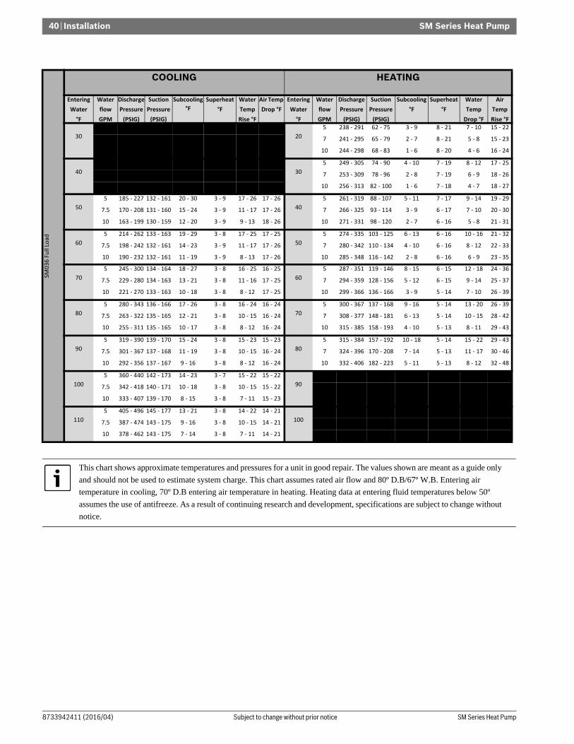
SM Series Heat Pump
SM Series Heat Pump8733942411 (2016/04) Subject to change without prior notice
40 | Installation
SM0
36
Fu
ll Lo
ad
COOLING HEATING
Entering
Water
°F
Water
flow
GPM
Discharge
Pressure
(PSIG)
Suction
Pressure
(PSIG)
Subcooling
°F
Superheat
°F
Water
Temp
Rise °F
Air Temp
Drop °F
Entering
Water
°F
Water
flow
GPM
Discharge
Pressure
(PSIG)
Suction
Pressure
(PSIG)
Subcooling
°F
Superheat
°F
Water
Temp
Drop °F
Air
Temp
Rise °F
30
5 171 - 175 134 - 140 27 - 30 6 - 8 20 - 25 22 - 27
20
5 238 - 291 62 - 75 3 - 9 8 - 21 7 - 10 15 - 22
7.5 150 - 153 133 - 138 20 - 22 6 - 8 14 - 17 22 - 27 7 241 - 295 65 - 79 2 - 7 8 - 21 5 - 8 15 - 23
10 140 - 143 133 - 138 17 - 18 6 - 8 10 - 13 22 - 27 10 244 - 298 68 - 83 1 - 6 8 - 20 4 - 6 16 - 24
40
5 160 - 195 130 - 159 9 - 24 3 - 9 9 - 25 18 - 27
30
5 249 - 305 74 - 90 4 - 10 7 - 19 8 - 12 17 - 25
7.5 145 - 178 129 - 158 6 - 16 3 - 9 6 - 17 18 - 27 7 253 - 309 78 - 96 2 - 8 7 - 19 6 - 9 18 - 26
10 138 - 169 128 - 157 4 - 12 3 - 9 5 - 12 18 - 27 10 256 - 313 82 - 100 1 - 6 7 - 18 4 - 7 18 - 27
50
5 185 - 227 132 - 161 20 - 30 3 - 9 17 - 26 17 - 26
40
5 261 - 319 88 - 107 5 - 11 7 - 17 9 - 14 19 - 29
7.5 170 - 208 131 - 160 15 - 24 3 - 9 11 - 17 17 - 26 7 266 - 325 93 - 114 3 - 9 6 - 17 7 - 10 20 - 30
10 163 - 199 130 - 159 12 - 20 3 - 9 9 - 13 18 - 26 10 271 - 331 98 - 120 2 - 7 6 - 16 5 - 8 21 - 31
60
5 214 - 262 133 - 163 19 - 29 3 - 8 17 - 25 17 - 25
50
5 274 - 335 103 - 125 6 - 13 6 - 16 10 - 16 21 - 32
7.5 198 - 242 132 - 161 14 - 23 3 - 9 11 - 17 17 - 26 7 280 - 342 110 - 134 4 - 10 6 - 16 8 - 12 22 - 33
10 190 - 232 132 - 161 11 - 19 3 - 9 8 - 13 17 - 26 10 285 - 348 116 - 142 2 - 8 6 - 16 6 - 9 23 - 35
70
5 245 - 300 134 - 164 18 - 27 3 - 8 16 - 25 16 - 25
60
5 287 - 351 119 - 146 8 - 15 6 - 15 12 - 18 24 - 36
7.5 229 - 280 134 - 163 13 - 21 3 - 8 11 - 16 17 - 25 7 294 - 359 128 - 156 5 - 12 6 - 15 9 - 14 25 - 37
10 221 - 270 133 - 163 10 - 18 3 - 8 8 - 12 17 - 25 10 299 - 366 136 - 166 3 - 9 5 - 14 7 - 10 26 - 39
80
5 280 - 343 136 - 166 17 - 26 3 - 8 16 - 24 16 - 24
70
5 300 - 367 137 - 168 9 - 16 5 - 14 13 - 20 26 - 39
7.5 263 - 322 135 - 165 12 - 21 3 - 8 10 - 15 16 - 24 7 308 - 377 148 - 181 6 - 13 5 - 14 10 - 15 28 - 42
10 255 - 311 135 - 165 10 - 17 3 - 8 8 - 12 16 - 24 10 315 - 385 158 - 193 4 - 10 5 - 13 8 - 11 29 - 43
90
5 319 - 390 139 - 170 15 - 24 3 - 8 15 - 23 15 - 23
80
5 315 - 384 157 - 192 10 - 18 5 - 14 15 - 22 29 - 43
7.5 301 - 367 137 - 168 11 - 19 3 - 8 10 - 15 16 - 24 7 324 - 396 170 - 208 7 - 14 5 - 13 11 - 17 30 - 46
10 292 - 356 137 - 167 9 - 16 3 - 8 8 - 12 16 - 24 10 332 - 406 182 - 223 5 - 11 5 - 13 8 - 12 32 - 48
100
5 360 - 440 142 - 173 14 - 23 3 - 7 15 - 22 15 - 22
90
5 330 - 403 179 - 218 12 - 20 5 - 13 16 - 24 31 - 47
7.5 342 - 418 140 - 171 10 - 18 3 - 8 10 - 15 15 - 22 7 340 - 416 195 - 238 8 - 16 5 - 13 12 - 19 33 - 50
10 333 - 407 139 - 170 8 - 15 3 - 8 7 - 11 15 - 23 10 350 - 427 209 - 255 6 - 12 5 - 13 9 - 14 35 - 52
110
5 405 - 496 145 - 177 13 - 21 3 - 8 14 - 22 14 - 21
100
5 345 - 422 202 - 247 14 - 22 5 - 12 18 - 27 34 - 51
7.5 387 - 474 143 - 175 9 - 16 3 - 8 10 - 15 14 - 21 7 358 - 437 221 - 270 10 - 17 5 - 13 14 - 20 36 - 54
10 378 - 462 143 - 175 7 - 14 3 - 8 7 - 11 14 - 21 10 369 - 450 239 - 292 6 - 13 5 - 12 10 - 15 38 - 57
This chart shows approximate temperatures and pressures for a unit in good repair. The values shown are meant as a guide only
and should not be used to estimate system charge. This chart assumes rated air flow and 80º D.B/67º W.B. Entering air
temperature in cooling, 70º D.B entering air temperature in heating. Heating data at entering fluid temperatures below 50º
assumes the use of antifreeze. As a result of continuing research and development, specifications are subject to change without
notice.

Installation | 41SM Series Heat Pump
8733942411 (2016/04)Revised 04-16
SM0
36
Par
t Lo
ad
COOLING HEATING
Entering
Water
°F
Water
flow
GPM
Discharge
Pressure
(PSIG)
Suction
Pressure
(PSIG)
Subcooling
°F
Superheat
°F
Water
Temp
Rise °F
Air Temp
Drop °F
Entering
Water
°F
Water
flow
GPM
Discharge
Pressure
(PSIG)
Suction
Pressure
(PSIG)
Subcooling
°F
Superheat
°F
Water
Temp
Drop °F
Air
Temp
Rise °F
30
5 150 - 153 140 - 145 16 - 17 5 - 6 15 - 18 20 - 25
20
5 221 - 270 67 - 82 1 - 6 9 - 23 5 - 7 12 - 18
7.5 136 - 138 139 - 144 11 - 12 5 - 6 10 - 12 21 - 25 7 223 - 273 70 - 86 1 - 6 8 - 22 3 - 5 12 - 18
10 128 - 131 139 - 144 8 - 9 5 - 6 7 - 9 21 - 25 10 225 - 275 73 - 89 1 - 6 8 - 21 2 - 4 12 - 18
40
5 198 - 242 122 - 149 18 - 47 4 - 10 14 - 38 20 - 30
30
5 231 - 283 81 - 99 2 - 7 7 - 19 6 - 8 13 - 20
7.5 173 - 212 121 - 147 13 - 35 4 - 10 10 - 26 20 - 30 7 234 - 286 84 - 103 1 - 6 7 - 18 4 - 6 14 - 21
10 161 - 197 120 - 146 10 - 28 4 - 10 7 - 19 20 - 30 10 236 - 288 87 - 107 1 - 6 7 - 18 3 - 5 14 - 21
50
5 226 - 276 123 - 151 11 - 19 4 - 11 12 - 18 19 - 29
40
5 242 - 295 96 - 118 3 - 9 6 - 17 7 - 10 16 - 23
7.5 200 - 245 122 - 149 7 - 14 4 - 10 8 - 12 20 - 29 7 245 - 299 101 - 123 1 - 7 6 - 16 5 - 7 16 - 24
10 187 - 229 121 - 148 5 - 11 4 - 10 6 - 9 20 - 30 10 247 - 302 105 - 128 1 - 6 6 - 16 4 - 6 17 - 25
60
5 257 - 314 125 - 153 10 - 18 4 - 12 12 - 18 19 - 28
50
5 253 - 309 113 - 138 4 - 10 6 - 15 8 - 12 18 - 27
7.5 230 - 282 124 - 151 6 - 13 4 - 11 8 - 12 19 - 29 7 257 - 314 119 - 145 2 - 8 5 - 14 6 - 9 18 - 28
10 217 - 265 123 - 150 4 - 11 4 - 11 6 - 9 19 - 29 10 260 - 318 124 - 151 1 - 6 5 - 14 4 - 6 19 - 28
70
5 292 - 357 127 - 155 9 - 17 4 - 12 11 - 17 18 - 27
60
5 265 - 324 131 - 160 5 - 11 5 - 14 9 - 13 20 - 30
7.5 264 - 322 125 - 153 6 - 12 4 - 12 8 - 11 19 - 28 7 270 - 330 139 - 169 3 - 9 5 - 13 7 - 10 21 - 31
10 250 - 305 125 - 153 4 - 10 4 - 11 6 - 8 19 - 28 10 274 - 335 145 - 177 2 - 7 5 - 13 5 - 7 21 - 32
80
5 330 - 403 129 - 157 8 - 16 5 - 12 11 - 16 18 - 27
70
5 278 - 339 151 - 185 6 - 13 5 - 13 10 - 15 22 - 33
7.5 301 - 367 127 - 156 5 - 11 4 - 12 7 - 11 18 - 27 7 283 - 345 161 - 196 4 - 10 5 - 12 8 - 12 23 - 35
10 286 - 349 126 - 155 3 - 9 4 - 12 5 - 8 18 - 28 10 287 - 351 169 - 206 2 - 8 4 - 12 6 - 8 24 - 36
90
5 371 - 454 132 - 161 8 - 15 4 - 10 11 - 16 17 - 25
80
5 290 - 354 173 - 212 7 - 14 4 - 12 11 - 17 24 - 36
7.5 340 - 416 129 - 158 4 - 10 5 - 12 7 - 10 18 - 27 7 295 - 361 185 - 226 5 - 11 4 - 11 9 - 13 25 - 38
10 325 - 398 128 - 157 3 - 8 5 - 12 5 - 8 18 - 27 10 301 - 368 195 - 239 3 - 9 4 - 11 6 - 9 26 - 40
100
5 415 - 507 134 - 163 7 - 13 4 - 10 10 - 16 16 - 24
90
5 302 - 369 198 - 242 9 - 16 4 - 11 13 - 19 27 - 40
7.5 383 - 468 129 - 157 4 - 10 6 - 16 7 - 10 18 - 27 7 309 - 378 212 - 259 6 - 12 4 - 11 10 - 14 28 - 42
10 369 - 451 130 - 159 2 - 8 5 - 13 5 - 8 17 - 26 10 315 - 385 224 - 274 4 - 9 4 - 11 7 - 11 29 - 44
110
5 461 - 563 133 - 163 6 - 12 5 - 14 10 - 15 16 - 25
100
5 315 - 386 224 - 274 10 - 18 4 - 11 14 - 21 29 - 44
7.5 431 - 527 131 - 160 3 - 9 6 - 15 7 - 10 17 - 26 7 323 - 395 241 - 295 7 - 14 4 - 10 11 - 16 31 - 46
10 418 - 510 134 - 163 2 - 7 4 - 11 5 - 7 16 - 24 10 331 - 404 256 - 313 4 - 10 4 - 10 8 - 12 32 - 48
This chart shows approximate temperatures and pressures for a unit in good repair. The values shown are meant as a guide only
and should not be used to estimate system charge. This chart assumes rated air flow and 80º D.B/67º W.B. Entering air
temperature in cooling, 70º D.B entering air temperature in heating. Heating data at entering fluid temperatures below 50º
assumes the use of antifreeze. As a result of continuing research and development, specifications are subject to change without
notice.

SM Series Heat Pump
SM Series Heat Pump8733942411 (2016/04) Subject to change without prior notice
42 | Installation
SM0
48
Fu
ll Lo
ad
COOLING HEATING
Entering
Water
°F
Water
flow
GPM
Discharge
Pressure
(PSIG)
Suction
Pressure
(PSIG)
Subcooling
°F
Superheat
°F
Water
Temp
Rise °F
Air Temp
Drop °F
Entering
Water
°F
Water
flow
GPM
Discharge
Pressure
(PSIG)
Suction
Pressure
(PSIG)
Subcooling
°F
Superheat
°F
Water
Temp
Drop °F
Air
Temp
Rise °F
30
6 188 - 192 131 - 136 29 - 33 6 - 7 22 - 27 23 - 28
20
6 246 - 301 65 - 79 3 - 9 8 - 20 7 - 10 16 - 24
9 163 - 167 129 - 135 22 - 24 6 - 7 15 - 18 23 - 28 9 251 - 306 69 - 84 1 - 7 7 - 20 5 - 7 16 - 25
12 151 - 154 128 - 134 18 - 20 5 - 7 11 - 14 23 - 29 12 253 - 310 71 - 87 1 - 6 7 - 19 4 - 6 17 - 25
40
6 173 - 212 126 - 154 8 - 22 3 - 9 11 - 28 20 - 29
30
6 259 - 316 76 - 93 4 - 10 7 - 18 8 - 12 18 - 27
9 156 - 190 125 - 153 8 - 21 3 - 9 7 - 19 20 - 30 9 264 - 323 81 - 100 2 - 8 7 - 18 6 - 9 19 - 28
12 147 - 180 124 - 152 8 - 21 3 - 9 6 - 15 20 - 30 12 268 - 327 84 - 103 1 - 6 7 - 17 4 - 7 19 - 29
50
6 200 - 245 128 - 156 22 - 33 3 - 9 18 - 28 19 - 29
40
6 272 - 332 88 - 108 5 - 11 6 - 17 9 - 14 20 - 30
9 182 - 222 127 - 155 16 - 25 3 - 9 12 - 19 19 - 29 9 279 - 340 95 - 117 3 - 9 6 - 16 7 - 10 21 - 32
12 173 - 211 126 - 154 13 - 21 3 - 9 9 - 14 20 - 29 12 282 - 345 99 - 121 2 - 7 6 - 16 5 - 8 22 - 33
60 6 230 - 281 130 - 159 21 - 31 3 - 8 18 - 27 19 - 28
50
6 285 - 348 102 - 125 6 - 13 6 - 16 10 - 16 22 - 34
9 211 - 258 129 - 157 15 - 24 3 - 9 12 - 18 19 - 28 9 293 - 358 111 - 135 4 - 10 6 - 15 8 - 11 24 - 36
12 201 - 246 128 - 156 12 - 20 3 - 9 9 - 14 19 - 29 12 297 - 364 116 - 142 2 - 8 6 - 15 6 - 9 25 - 37
70
6 263 - 321 131 - 161 20 - 30 3 - 8 18 - 26 18 - 27
60
6 299 - 365 118 - 144 8 - 15 6 - 15 12 - 18 25 - 38
9 243 - 297 130 - 159 14 - 23 3 - 8 12 - 18 18 - 27 9 308 - 377 128 - 157 5 - 11 5 - 14 8 - 13 27 - 40
12 233 - 284 130 - 159 11 - 19 3 - 9 9 - 13 18 - 28 12 314 - 383 134 - 164 3 - 9 5 - 14 7 - 10 28 - 42
80
6 299 - 365 133 - 163 18 - 28 3 - 8 17 - 26 18 - 26
70
6 313 - 383 134 - 164 9 - 16 5 - 14 13 - 20 28 - 42
9 279 - 341 132 - 161 13 - 22 3 - 8 12 - 17 18 - 27 9 324 - 396 147 - 180 6 - 12 5 - 14 10 - 14 30 - 44
12 268 - 328 132 - 161 10 - 18 3 - 8 9 - 13 18 - 27 12 331 - 405 155 - 189 4 - 10 5 - 13 8 - 11 31 - 46
90
6 337 - 412 135 - 165 17 - 27 3 - 8 16 - 25 17 - 25
80
6 329 - 402 153 - 187 11 - 18 5 - 13 15 - 22 30 - 45
9 317 - 387 134 - 164 12 - 20 3 - 8 11 - 17 17 - 26 9 342 - 418 168 - 206 7 - 14 5 - 13 11 - 16 32 - 49
12 306 - 374 134 - 163 10 - 17 3 - 8 9 - 13 17 - 26 12 349 - 427 178 - 217 5 - 11 5 - 13 8 - 12 34 - 51
100
6 377 - 461 137 - 168 16 - 25 3 - 8 16 - 24 16 - 25
90
6 345 - 422 173 - 211 12 - 20 5 - 13 16 - 25 33 - 50
9 357 - 437 137 - 167 11 - 19 3 - 8 11 - 17 17 - 25 9 361 - 441 192 - 234 8 - 15 5 - 13 12 - 18 36 - 53
12 347 - 424 136 - 166 9 - 16 3 - 8 8 - 12 17 - 25 12 370 - 452 203 - 249 6 - 12 5 - 12 9 - 14 37 - 55
110
6 420 - 514 140 - 171 14 - 23 3 - 8 16 - 24 16 - 24
100
6 363 - 443 195 - 238 14 - 22 5 - 12 18 - 27 36 - 54
9 401 - 490 139 - 170 10 - 18 3 - 8 11 - 16 16 - 24 9 380 - 464 217 - 266 9 - 16 5 - 12 13 - 19 39 - 58
12 390 - 477 138 - 169 8 - 15 3 - 8 8 - 12 16 - 24 12 390 - 477 232 - 283 6 - 13 5 - 12 10 - 15 40 - 60
This chart shows approximate temperatures and pressures for a unit in good repair. The values shown are meant as a guide only
and should not be used to estimate system charge. This chart assumes rated air flow and 80º D.B/67º W.B. Entering air
temperature in cooling, 70º D.B entering air temperature in heating. Heating data at entering fluid temperatures below 50º
assumes the use of antifreeze. As a result of continuing research and development, specifications are subject to change without
notice.

Installation | 43SM Series Heat Pump
8733942411 (2016/04)Revised 04-16
SM0
48
Par
t Lo
ad
COOLING HEATING
Entering
Water
°F
Water
flow
GPM
Discharge
Pressure
(PSIG)
Suction
Pressure
(PSIG)
Subcooling
°F
Superheat
°F
Water
Temp
Rise °F
Air Temp
Drop °F
Entering
Water
°F
Water
flow
GPM
Discharge
Pressure
(PSIG)
Suction
Pressure
(PSIG)
Subcooling
°F
Superheat
°F
Water
Temp
Drop °F
Air Temp
Rise °F
30
6 164 - 167 135 - 141 14 - 15 5 - 6 17 - 20 23 - 28
20
6 237 - 290 65 - 79 4 - 10 8 - 20 5 - 8 15 - 22
9 145 - 148 134 - 139 13 - 14 5 - 6 11 - 14 23 - 28 9 240 - 293 68 - 83 3 - 9 7 - 19 4 - 5 15 - 23
12 136 - 139 133 - 139 13 - 14 5 - 6 9 - 10 23 - 28 12 242 - 295 70 - 86 2 - 8 7 - 19 3 - 4 16 - 24
40
6 206 - 251 119 - 146 20 - 53 7 - 18 15 - 40 20 - 30
30
6 248 - 303 78 - 95 5 - 11 7 - 17 6 - 9 17 - 26
9 177 - 216 118 - 144 14 - 38 6 - 17 9 - 24 21 - 31 9 252 - 308 82 - 100 4 - 10 6 - 17 4 - 6 18 - 27
12 169 - 206 117 - 143 12 - 33 6 - 17 7 - 19 21 - 31 12 254 - 311 85 - 104 3 - 9 6 - 16 3 - 5 18 - 27
50
6 234 - 286 121 - 148 10 - 18 7 - 18 14 - 21 20 - 30
40
6 261 - 319 92 - 113 6 - 13 6 - 15 7 - 11 19 - 29
9 203 - 248 119 - 146 10 - 17 6 - 15 9 - 14 20 - 30 9 266 - 325 98 - 120 4 - 10 6 - 15 5 - 8 20 - 30
12 195 - 238 119 - 145 10 - 17 7 - 17 7 - 11 20 - 30 12 269 - 328 101 - 124 3 - 9 5 - 15 4 - 6 21 - 31
60
6 265 - 324 123 - 150 10 - 17 7 - 18 13 - 20 19 - 29
50
6 275 - 336 108 - 132 7 - 14 5 - 14 8 - 12 22 - 32
9 233 - 284 121 - 148 10 - 17 7 - 18 9 - 14 20 - 30 9 280 - 342 115 - 141 5 - 11 5 - 13 6 - 9 23 - 34
12 224 - 274 120 - 147 9 - 17 7 - 18 7 - 10 20 - 30 12 283 - 346 120 - 146 4 - 10 5 - 13 4 - 7 23 - 35
70
6 300 - 366 125 - 152 9 - 16 7 - 18 13 - 19 19 - 28
60
6 287 - 351 125 - 153 8 - 15 5 - 13 9 - 14 24 - 36
9 266 - 325 123 - 150 9 - 16 7 - 18 9 - 13 19 - 29 9 294 - 360 135 - 164 6 - 12 5 - 12 7 - 10 25 - 38
12 257 - 314 122 - 149 9 - 16 7 - 18 7 - 10 19 - 29 12 299 - 365 140 - 171 4 - 11 5 - 12 5 - 8 26 - 39
80
6 337 - 411 126 - 154 8 - 15 7 - 19 12 - 19 18 - 27
70
6 302 - 369 144 - 176 9 - 17 5 - 12 11 - 16 27 - 40
9 302 - 369 125 - 152 8 - 16 7 - 18 8 - 13 19 - 28 9 310 - 379 156 - 191 7 - 13 4 - 12 8 - 11 28 - 42
12 293 - 358 124 - 152 8 - 16 7 - 18 6 - 9 19 - 28 12 315 - 384 163 - 199 5 - 11 4 - 11 6 - 9 29 - 44
90
6 377 - 461 128 - 156 7 - 14 7 - 19 12 - 18 18 - 27
80
6 316 - 387 166 - 202 11 - 18 4 - 11 12 - 18 29 - 44
9 342 - 418 126 - 154 8 - 15 7 - 18 8 - 12 18 - 27 9 327 - 399 179 - 219 8 - 14 4 - 11 8 - 13 31 - 47
12 333 - 407 126 - 154 8 - 15 7 - 18 6 - 9 18 - 27 12 332 - 406 188 - 230 6 - 12 4 - 11 7 - 10 32 - 48
100
6 421 - 515 129 - 158 6 - 13 7 - 19 12 - 18 17 - 26
90
6 332 - 406 188 - 230 12 - 20 4 - 11 13 - 20 32 - 48
9 386 - 472 128 - 156 7 - 14 7 - 19 8 - 12 18 - 27 9 344 - 420 206 - 251 8 - 16 4 - 10 9 - 14 34 - 51
12 377 - 461 128 - 156 7 - 14 7 - 19 6 - 9 18 - 27 12 351 - 429 216 - 264 7 - 13 4 - 10 7 - 11 35 - 53
110
6 469 - 573 131 - 160 5 - 11 7 - 20 11 - 17 17 - 25
100
6 349 - 427 213 - 261 13 - 21 4 - 10 14 - 22 35 - 52
9 435 - 531 130 - 158 6 - 12 7 - 20 8 - 12 17 - 26 9 362 - 443 234 - 286 9 - 17 4 - 10 10 - 15 37 - 56
12 426 - 520 129 - 158 6 - 13 7 - 19 6 - 9 17 - 26 12 370 - 452 247 - 301 7 - 14 4 - 10 8 - 12 38 - 58
This chart shows approximate temperatures and pressures for a unit in good repair. The values shown are meant as a guide only
and should not be used to estimate system charge. This chart assumes rated air flow and 80º D.B/67º W.B. Entering air
temperature in cooling, 70º D.B entering air temperature in heating. Heating data at entering fluid temperatures below 50º
assumes the use of antifreeze. As a result of continuing research and development, specifications are subject to change without
notice.

SM Series Heat Pump
SM Series Heat Pump8733942411 (2016/04) Subject to change without prior notice
44 | Installation
SM0
60
Fu
ll Lo
ad
COOLING HEATING
Entering
Water
°F
Water
flow
GPM
Discharge
Pressure
(PSIG)
Suction
Pressure
(PSIG)
Subcooling
°F
Superheat
°F
Water
Temp Rise
°F
Air Temp
Drop °F
Entering
Water
°F
Water
flow
GPM
Discharge
Pressure
(PSIG)
Suction
Pressure
(PSIG)
Subcooling
°F
Superheat
°F
Water
Temp
Drop °F
Air
Temp
Rise °F
30
7 198 - 202 128 - 134 33 - 36 10 - 12 23 - 28 23 - 28
20
7 262 - 321 56 - 69 12 - 20 9 - 24 7 - 11 17 - 26
12 168 - 172 126 - 132 24 - 26 10 - 12 14 - 17 24 - 29 12 269 - 329 62 - 76 9 - 17 9 - 23 5 - 7 18 - 27
15 161 - 164 126 - 131 21 - 23 9 - 11 11 - 13 24 - 29 15 271 - 332 64 - 78 9 - 16 9 - 23 4 - 6 19 - 28
40
7 206 - 251 119 - 146 20 - 53 7 - 18 15 - 40 20 - 30
30
7 276 - 337 68 - 83 13 - 21 8 - 23 9 - 13 19 - 29
12 177 - 216 118 - 144 14 - 38 6 - 17 9 - 24 21 - 31 12 284 - 347 75 - 91 10 - 18 8 - 22 5 - 8 21 - 31
15 169 - 206 117 - 143 12 - 33 6 - 17 7 - 19 21 - 31 15 286 - 350 77 - 94 9 - 17 8 - 22 4 - 7 21 - 32
50
7 234 - 286 121 - 148 25 - 36 7 - 18 20 - 30 20 - 30
40
7 290 - 354 80 - 98 14 - 22 8 - 21 10 - 15 22 - 33
12 203 - 248 119 - 146 18 - 27 6 - 15 12 - 17 20 - 30 12 299 - 366 89 - 109 11 - 19 8 - 21 6 - 9 24 - 35
15 195 - 238 119 - 145 16 - 25 7 - 17 9 - 14 20 - 30 15 302 - 369 92 - 112 10 - 17 8 - 20 5 - 8 24 - 36
60
7 265 - 324 123 - 150 24 - 35 7 - 18 19 - 29 19 - 29
50
7 304 - 372 94 - 115 15 - 24 8 - 20 11 - 17 24 - 37
12 233 - 284 121 - 148 17 - 26 7 - 18 11 - 17 20 - 30 12 315 - 386 104 - 128 12 - 20 8 - 20 7 - 11 26 - 39
15 224 - 274 120 - 147 15 - 24 7 - 18 9 - 13 20 - 30 15 319 - 390 108 - 132 11 - 18 7 - 20 6 - 9 27 - 40
70
7 300 - 366 125 - 152 23 - 33 7 - 18 19 - 28 19 - 28
60
7 320 - 391 109 - 133 17 - 26 7 - 20 13 - 19 27 - 41
12 266 - 325 123 - 150 16 - 25 7 - 18 11 - 16 19 - 29 12 334 - 408 123 - 150 13 - 21 7 - 19 8 - 12 29 - 44
15 257 - 314 122 - 149 14 - 23 7 - 18 9 - 13 19 - 29 15 338 - 414 127 - 155 11 - 19 7 - 19 7 - 10 30 - 45
80
7 337 - 411 126 - 154 21 - 32 7 - 19 18 - 27 18 - 27
70
7 337 - 412 126 - 154 18 - 28 7 - 19 14 - 21 30 - 45
12 302 - 369 125 - 152 15 - 24 7 - 18 11 - 16 19 - 28 12 353 - 432 142 - 174 14 - 22 7 - 19 9 - 14 33 - 49
15 293 - 358 124 - 152 13 - 22 7 - 18 8 - 13 19 - 28 15 359 - 438 148 - 181 12 - 20 7 - 18 8 - 11 33 - 50
90
7 377 - 461 128 - 156 20 - 30 7 - 19 18 - 27 18 - 27
80
7 355 - 434 144 - 176 20 - 30 7 - 18 16 - 24 33 - 49
12 342 - 418 126 - 154 14 - 23 7 - 18 10 - 15 18 - 27 12 374 - 457 164 - 201 15 - 23 7 - 18 10 - 15 36 - 54
15 333 - 407 126 - 154 13 - 21 7 - 18 8 - 12 18 - 27 15 380 - 465 171 - 209 13 - 21 7 - 18 8 - 13 37 - 55
100
7 421 - 515 129 - 158 19 - 29 7 - 19 18 - 26 17 - 26
90
7 373 - 456 164 - 200 21 - 32 7 - 18 18 - 26 36 - 54
12 386 - 472 128 - 156 14 - 22 7 - 19 10 - 15 18 - 27 12 396 - 484 189 - 231 16 - 25 7 - 18 11 - 17 39 - 59
15 377 - 461 128 - 156 12 - 20 7 - 19 8 - 12 18 - 27 15 403 - 493 197 - 241 14 - 22 7 - 18 9 - 14 40 - 60
110
7 469 - 573 131 - 160 18 - 27 7 - 20 17 - 26 17 - 25
100
7 393 - 481 186 - 227 23 - 34 7 - 18 19 - 29 39 - 58
12 435 - 531 130 - 158 13 - 21 7 - 20 10 - 15 17 - 26 12 418 - 511 216 - 264 17 - 26 7 - 17 12 - 18 42 - 63
15 426 - 520 129 - 158 12 - 19 7 - 19 8 - 12 17 - 26 15 426 - 521 226 - 277 15 - 23 6 - 17 10 - 15 44 - 65
This chart shows approximate temperatures and pressures for a unit in good repair. The values shown are meant as a guide only
and should not be used to estimate system charge. This chart assumes rated air flow and 80º D.B/67º W.B. Entering air
temperature in cooling, 70º D.B entering air temperature in heating. Heating data at entering fluid temperatures below 50º
assumes the use of antifreeze. As a result of continuing research and development, specifications are subject to change without
notice.

Installation | 45SM Series Heat Pump
8733942411 (2016/04)Revised 04-16
SM0
60
Par
t Lo
ad
COOLING HEATING
Entering
Water
°F
Water
flow
GPM
Discharge
Pressure
(PSIG)
Suction
Pressure
(PSIG)
Subcooling
°F
Superheat
°F
Water
Temp
Rise °F
Air Temp
Drop °F
Entering
Water
°F
Water
flow
GPM
Discharge
Pressure
(PSIG)
Suction
Pressure
(PSIG)
Subcooling
°F
Superheat °F Water
Temp
Drop °F
Air
Temp
Rise °F
30
7 162 - 166 134 - 140 21 - 23 8 - 10 18 - 22 23 - 28
20
7 246 - 300 64 - 79 7 - 14 7 - 20 5 - 8 16 - 23
12 140 - 143 132 - 138 13 - 15 8 - 9 11 - 13 24 - 29 12 250 - 306 69 - 84 5 - 12 7 - 19 3 - 5 16 - 24
15 135 - 137 132 - 137 11 - 13 8 - 9 9 - 11 24 - 29 15 251 - 307 71 - 86 5 - 11 7 - 18 3 - 4 17 - 25
40
7 171 - 209 125 - 153 12 - 33 5 - 15 12 - 31 20 - 30
30
7 258 - 316 77 - 95 8 - 15 7 - 17 6 - 10 18 - 27
12 150 - 183 123 - 151 8 - 21 5 - 14 7 - 19 20 - 31 12 264 - 323 83 - 102 6 - 12 6 - 17 4 - 6 19 - 28
15 144 - 176 123 - 150 6 - 17 5 - 14 6 - 15 21 - 31 15 266 - 325 85 - 104 5 - 12 6 - 17 3 - 5 19 - 29
50
7 198 - 242 127 - 155 15 - 24 6 - 15 15 - 23 20 - 29
40
7 273 - 333 92 - 113 9 - 16 6 - 16 8 - 12 20 - 30
12 176 - 215 125 - 153 9 - 17 5 - 14 9 - 13 20 - 30 12 280 - 342 99 - 121 6 - 13 6 - 15 5 - 7 21 - 32
15 169 - 207 125 - 153 8 - 15 5 - 14 7 - 11 20 - 30 15 282 - 345 102 - 125 6 - 12 6 - 15 4 - 6 22 - 33
60
7 228 - 278 129 - 158 14 - 23 6 - 15 14 - 22 19 - 28
50
7 287 - 350 108 - 132 10 - 18 6 - 15 9 - 13 23 - 34
12 204 - 249 127 - 156 9 - 16 6 - 15 9 - 13 19 - 29 12 295 - 360 117 - 143 7 - 14 5 - 14 6 - 8 24 - 36
15 197 - 241 127 - 155 7 - 14 6 - 15 7 - 11 20 - 29 15 297 - 364 120 - 147 6 - 13 5 - 14 4 - 7 25 - 37
70
7 259 - 317 131 - 160 13 - 21 6 - 15 14 - 21 18 - 27
60
7 301 - 368 125 - 153 11 - 19 5 - 14 10 - 15 25 - 38
12 235 - 287 129 - 158 8 - 15 6 - 15 8 - 13 19 - 28 12 311 - 380 137 - 168 8 - 15 5 - 13 6 - 9 27 - 41
15 229 - 279 129 - 158 6 - 13 6 - 15 7 - 10 19 - 28 15 314 - 384 141 - 173 7 - 14 5 - 13 5 - 8 28 - 41
80
7 295 - 360 133 - 162 12 - 20 6 - 16 14 - 20 18 - 27
70
7 317 - 387 144 - 176 12 - 21 5 - 13 11 - 17 28 - 42
12 270 - 330 132 - 161 7 - 14 6 - 16 8 - 12 18 - 27 12 328 - 401 159 - 195 9 - 16 5 - 12 7 - 11 30 - 45
15 263 - 321 131 - 160 6 - 12 6 - 16 7 - 10 18 - 28 15 332 - 406 164 - 201 8 - 15 5 - 12 6 - 9 31 - 46
90
7 333 - 407 135 - 165 11 - 18 6 - 16 13 - 20 17 - 26
80
7 333 - 407 166 - 202 14 - 22 5 - 12 13 - 19 31 - 46
12 308 - 377 134 - 163 6 - 13 6 - 16 8 - 12 18 - 27 12 346 - 423 184 - 225 10 - 17 5 - 12 8 - 12 33 - 50
15 301 - 368 133 - 163 5 - 11 6 - 16 6 - 9 18 - 27 15 351 - 429 190 - 233 8 - 15 4 - 12 7 - 10 34 - 51
100
7 373 - 456 137 - 167 9 - 16 6 - 17 13 - 19 17 - 25
90
7 350 - 428 189 - 231 15 - 24 4 - 12 14 - 21 34 - 50
12 349 - 427 136 - 166 5 - 12 6 - 17 8 - 11 17 - 26 12 366 - 447 211 - 258 10 - 18 4 - 12 9 - 13 36 - 54
15 343 - 419 135 - 166 4 - 10 6 - 17 6 - 9 17 - 26 15 370 - 453 219 - 267 9 - 16 4 - 12 7 - 11 37 - 55
110
7 417 - 509 139 - 170 8 - 15 7 - 18 12 - 19 16 - 24
100
7 368 - 449 214 - 262 16 - 26 4 - 12 15 - 23 36 - 54
12 394 - 482 138 - 169 4 - 11 7 - 17 7 - 11 17 - 25 12 386 - 471 241 - 295 11 - 19 4 - 11 10 - 15 39 - 59
15 388 - 474 138 - 168 3 - 9 6 - 17 6 - 9 17 - 25 15 391 - 478 250 - 306 10 - 17 4 - 11 8 - 12 40 - 60
This chart shows approximate temperatures and pressures for a unit in good repair. The values shown are meant as a guide only
and should not be used to estimate system charge. This chart assumes rated air flow and 80º D.B/67º W.B. Entering air
temperature in cooling, 70º D.B entering air temperature in heating. Heating data at entering fluid temperatures below 50º
assumes the use of antifreeze. As a result of continuing research and development, specifications are subject to change without
notice.

SM Series Heat Pump
SM Series Heat Pump8733942411 (2016/04) Subject to change without prior notice
46 | Installation
SM0
70
Fu
ll Lo
ad
COOLING HEATING
Entering
Water
°F
Water
flow
GPM
Discharge
Pressure
(PSIG)
Suction
Pressure
(PSIG)
Subcooling
°F
Superheat
°F
Water
Temp
Rise °F
Air
Temp
Drop °F
Entering
Water
°F
Water
flow
GPM
Discharge
Pressure
(PSIG)
Suction
Pressure
(PSIG)
Subcooling
°F
Superheat
°F
Water
Temp
Drop °F
Air
Temp
Rise °F
30
9 170 - 174 135 - 141 20 - 22 8 - 9 16 - 20 20 - 24
20
9 265 - 324 57 - 70 8 - 16 8 - 22 7 - 10 18 - 26
15 151 - 154 134 - 140 13 - 15 7 - 9 10 - 12 20 - 25 12 269 - 328 60 - 73 7 - 14 8 - 21 6 - 8 18 - 27
18 147 - 150 134 - 139 12 - 13 8 - 9 8 - 10 20 - 25 18 272 - 332 63 - 77 6 - 12 8 - 21 4 - 6 19 - 28
40
9 178 - 218 125 - 153 11 - 31 5 - 14 11 - 28 17 - 26
30
9 279 - 340 69 - 84 9 - 17 8 - 20 8 - 12 20 - 30
15 160 - 196 124 - 152 8 - 20 5 - 14 6 - 17 18 - 26 12 282 - 345 72 - 88 8 - 15 8 - 20 6 - 9 20 - 30
18 155 - 190 124 - 152 7 - 17 5 - 14 5 - 14 18 - 27 18 287 - 351 76 - 93 6 - 13 7 - 20 5 - 7 21 - 32
50
9 205 - 251 127 - 156 14 - 23 5 - 14 14 - 20 17 - 25
40
9 293 - 358 81 - 99 10 - 18 7 - 19 9 - 14 22 - 33
15 185 - 226 126 - 154 9 - 16 5 - 14 8 - 12 17 - 26 12 297 - 364 86 - 105 9 - 16 7 - 19 7 - 11 23 - 35
18 180 - 220 125 - 153 8 - 15 5 - 14 7 - 11 17 - 26 18 303 - 370 91 - 111 7 - 14 7 - 19 5 - 8 24 - 36
60
9 234 - 286 127 - 156 13 - 22 5 - 14 13 - 20 16 - 25
50
9 308 - 377 95 - 117 12 - 20 7 - 19 10 - 16 25 - 37
15 213 - 261 126 - 154 8 - 15 5 - 15 8 - 12 17 - 25 12 314 - 384 101 - 124 10 - 17 7 - 18 8 - 12 26 - 39
18 208 - 255 125 - 153 7 - 14 5 - 14 7 - 10 17 - 25 18 321 - 393 108 - 132 8 - 15 7 - 18 6 - 9 27 - 40
70
9 267 - 327 129 - 157 12 - 20 5 - 13 13 - 19 16 - 24
60
9 325 - 397 111 - 136 13 - 21 7 - 18 12 - 18 28 - 41
15 245 - 299 127 - 156 8 - 14 6 - 15 8 - 12 16 - 25 12 332 - 406 118 - 145 11 - 18 6 - 17 9 - 14 29 - 43
18 239 - 293 127 - 156 6 - 13 5 - 15 7 - 10 16 - 25 18 341 - 416 127 - 155 8 - 16 6 - 17 7 - 10 30 - 45
80
9 302 - 369 132 - 161 11 - 19 6 - 15 13 - 19 16 - 24
70
9 343 - 419 128 - 157 14 - 23 6 - 17 13 - 20 30 - 45
15 279 - 341 129 - 158 7 - 13 6 - 17 8 - 12 16 - 24 12 351 - 429 137 - 167 12 - 20 6 - 17 10 - 16 32 - 47
18 275 - 336 129 - 158 6 - 12 5 - 13 6 - 9 16 - 23 18 362 - 442 148 - 180 9 - 16 6 - 17 7 - 11 33 - 50
90
9 341 - 416 132 - 161 10 - 18 6 - 16 12 - 19 15 - 23
80
9 362 - 442 147 - 180 16 - 25 6 - 17 15 - 22 33 - 50
15 318 - 388 130 - 158 6 - 13 6 - 16 7 - 11 16 - 23 12 371 - 454 158 - 193 13 - 21 6 - 17 12 - 17 35 - 52
18 312 - 381 132 - 161 5 - 11 6 - 16 6 - 9 16 - 23 18 384 - 469 171 - 209 10 - 17 6 - 16 8 - 12 36 - 55
100
9 383 - 468 134 - 163 9 - 16 6 - 16 12 - 18 15 - 22
90
9 381 - 466 168 - 205 17 - 26 6 - 16 16 - 24 36 - 54
15 360 - 440 132 - 162 5 - 12 6 - 16 7 - 11 15 - 23 12 393 - 481 181 - 222 14 - 23 6 - 16 13 - 19 38 - 57
18 354 - 433 132 - 161 4 - 10 6 - 16 6 - 9 15 - 23 18 407 - 497 196 - 240 11 - 18 6 - 16 9 - 14 40 - 60
110
9 429 - 524 135 - 165 8 - 15 7 - 18 12 - 18 14 - 22
100
9 402 - 491 191 - 234 18 - 28 6 - 16 18 - 26 39 - 59
15 406 - 496 134 - 164 5 - 11 6 - 16 7 - 11 14 - 22 12 416 - 508 207 - 253 15 - 24 6 - 16 14 - 21 41 - 62
18 400 - 489 134 - 164 4 - 10 6 - 17 6 - 9 15 - 22 18 431 - 527 225 - 275 11 - 19 6 - 16 10 - 15 43 - 65
This chart shows approximate temperatures and pressures for a unit in good repair. The values shown are meant as a guide only
and should not be used to estimate system charge. This chart assumes rated air flow and 80º D.B/67º W.B. Entering air
temperature in cooling, 70º D.B entering air temperature in heating. Heating data at entering fluid temperatures below 50º
assumes the use of antifreeze. As a result of continuing research and development, specifications are subject to change without
notice.

Installation | 47SM Series Heat Pump
8733942411 (2016/04)Revised 04-16
SM0
70
Par
t Lo
ad
COOLING HEATING
Entering
Water
°F
Water
flow
GPM
Discharge
Pressure
(PSIG)
Suction
Pressure
(PSIG)
Subcooling
°F
Superheat
°F
Water
Temp
Rise °F
Air Temp
Drop °F
Entering
Water
°F
Water
flow
GPM
Discharge
Pressure
(PSIG)
Suction
Pressure
(PSIG)
Subcooling
°F
Superheat
°F
Water
Temp
Drop °F
Air
Temp
Rise °F
30
9 170 - 174 135 - 141 20 - 22 8 - 9 16 - 20 20 - 24
20
9 253 - 310 65 - 79 7 - 14 7 - 17 5 - 8 17 - 25
15 151 - 154 134 - 140 13 - 15 7 - 9 10 - 12 20 - 25 12 256 - 312 67 - 82 6 - 12 6 - 17 4 - 6 17 - 26
18 147 - 150 134 - 139 12 - 13 8 - 9 8 - 10 20 - 25 18 259 - 316 70 - 85 5 - 11 6 - 17 3 - 4 18 - 27
40
9 196 - 200 137 - 142 18 - 20 8 - 10 16 - 20 20 - 24
30
9 267 - 327 78 - 95 8 - 15 6 - 16 6 - 9 19 - 29
15 176 - 180 136 - 141 12 - 13 8 - 9 10 - 12 20 - 24 12 271 - 331 81 - 99 7 - 13 6 - 15 5 - 7 20 - 30
18 171 - 174 135 - 141 10 - 11 8 - 9 8 - 10 20 - 24 18 275 - 336 84 - 103 5 - 12 6 - 15 3 - 5 20 - 30
50
9 226 - 230 139 - 144 14 - 23 8 - 10 14 - 20 19 - 23
40
9 282 - 344 92 - 113 9 - 16 5 - 14 7 - 11 22 - 32
15 204 - 208 137 - 143 9 - 16 8 - 10 8 - 12 19 - 24 12 285 - 349 96 - 117 7 - 14 5 - 14 6 - 9 22 - 33
18 198 - 202 137 - 142 8 - 15 8 - 10 7 - 11 20 - 24 18 290 - 354 101 - 123 6 - 12 5 - 14 4 - 6 23 - 35
60
9 258 - 263 139 - 144 13 - 22 8 - 10 13 - 20 19 - 23
50
9 297 - 362 108 - 132 10 - 17 5 - 13 8 - 12 24 - 36
15 234 - 239 137 - 143 8 - 15 8 - 10 8 - 12 19 - 23 12 301 - 368 113 - 138 8 - 15 5 - 13 7 - 10 25 - 38
18 229 - 234 137 - 142 7 - 14 8 - 10 7 - 10 19 - 23 18 306 - 374 119 - 145 6 - 13 5 - 13 5 - 7 26 - 39
70
9 294 - 300 140 - 146 12 - 20 7 - 9 13 - 19 18 - 22
60
9 312 - 382 125 - 153 11 - 18 5 - 12 9 - 14 27 - 40
15 269 - 275 139 - 144 8 - 14 8 - 10 8 - 12 18 - 23 12 318 - 389 132 - 161 9 - 16 5 - 12 7 - 11 28 - 42
18 263 - 269 139 - 144 6 - 13 8 - 10 7 - 10 19 - 23 18 325 - 397 139 - 170 7 - 14 5 - 12 5 - 8 29 - 44
80
9 332 - 339 143 - 149 11 - 19 9 - 10 13 - 19 18 - 22
70
9 330 - 403 145 - 177 12 - 20 4 - 12 11 - 16 30 - 45
15 307 - 313 141 - 147 7 - 13 9 - 12 8 - 12 18 - 22 12 337 - 411 153 - 187 10 - 17 4 - 12 8 - 13 31 - 46
18 302 - 308 141 - 146 6 - 12 7 - 9 6 - 9 18 - 21 18 344 - 421 162 - 198 8 - 15 4 - 11 6 - 9 32 - 48
90
9 375 - 382 143 - 149 10 - 18 9 - 11 12 - 19 17 - 21
80
9 348 - 425 167 - 204 13 - 21 4 - 11 12 - 18 33 - 49
15 349 - 356 141 - 147 6 - 13 9 - 11 7 - 11 18 - 21 12 356 - 435 176 - 215 11 - 19 4 - 11 9 - 14 34 - 51
18 343 - 350 144 - 149 5 - 11 9 - 11 6 - 9 18 - 21 18 366 - 447 188 - 229 8 - 15 4 - 11 7 - 10 36 - 53
100
9 421 - 430 145 - 151 9 - 16 9 - 11 12 - 18 17 - 20
90
9 368 - 449 190 - 233 14 - 23 4 - 11 13 - 20 36 - 54
15 396 - 404 144 - 150 5 - 12 9 - 11 7 - 11 17 - 21 12 377 - 461 202 - 247 12 - 20 4 - 11 10 - 15 37 - 56
18 389 - 397 144 - 150 4 - 10 9 - 11 6 - 9 17 - 21 18 388 - 474 216 - 264 9 - 16 4 - 10 7 - 11 39 - 58
110
9 471 - 481 147 - 153 8 - 15 10 - 12 12 - 18 16 - 20
100
9 388 - 474 216 - 264 16 - 24 4 - 11 14 - 22 39 - 58
15 446 - 455 146 - 152 5 - 11 9 - 11 7 - 11 16 - 20 12 399 - 488 230 - 281 13 - 21 4 - 10 11 - 17 41 - 61
18 440 - 449 146 - 152 4 - 10 9 - 11 6 - 9 16 - 20 18 411 - 503 247 - 302 10 - 17 4 - 10 8 - 12 42 - 64
This chart shows approximate temperatures and pressures for a unit in good repair. The values shown are meant as a guide only
and should not be used to estimate system charge. This chart assumes rated air flow and 80º D.B/67º W.B. Entering air
temperature in cooling, 70º D.B entering air temperature in heating. Heating data at entering fluid temperatures below 50º
assumes the use of antifreeze. As a result of continuing research and development, specifications are subject to change without
notice.

SM Series Heat Pump
SM Series Heat Pump8733942411 (2016/04) Subject to change without prior notice
48 | Installation
BLOWER PERFORMANCE DATA(HZ) UNITS REV A
ECM Const CFM Motor - EONModels Fan Speed Rated Airflow Tap External Static Pressure (in of Water)
Adjust 0.10 0.20 0.30 0.40 0.50 0.60 0.70 0.80 0.90 1.00
SM024Part Load
Hi 725 + A 725 725 725 725 725 725 725 725 - -
Med 650 Normal A 650 650 650 650 650 650 650 650 - -
Low 500 - A 500 500 500 500 500 500 500 500 - -
SM024 Full Load
Hi 950 + A 950 950 950 950 950 950 950 950 - -
Med 825 Normal A 825 825 825 825 825 825 825 825 - -
Low 725 - A 725 725 725 725 725 725 725 725 - -
SM036 Part Load
Hi 950 + A 950 950 950 950 950 950 950 950 950 950
Med 800 Normal A 800 800 800 800 800 800 800 800 800 800
Low 750 - A 750 750 750 750 750 750 750 750 750 750
SM036Full Load
Hi 1300 + A 1300 1300 1300 1300 1300 1300 1300 1300 1300 1300
Med 1100 Normal A 1100 1100 1100 1100 1100 1100 1100 1100 1100 1100
Low 950 - A 950 950 950 950 950 950 950 950 950 950
SM048Part Load
Hi 1400 + A 1400 1400 1400 1400 1400 1400 1400 1400 1400 1400
Med 1300 Normal A 1300 1300 1300 1300 1300 1300 1300 1300 1300 1300
Low 1100 - A 1100 1100 1100 1100 1100 1100 1100 1100 1100 1100
SM048Full Load
Hi 1800 + A 1800 1800 1800 1800 1800 1800 1800 1800 1800 1800
Med 1600 Normal A 1600 1600 1600 1600 1600 1600 1600 1600 1600 1600
Low 1400 - A 1400 1400 1400 1400 1400 1400 1400 1400 1400 1400
SM060 Part Load
Hi 1800 + A 1800 1800 1800 1800 1800 1800 1800 1800 1800 1800
Med 1600 Normal A 1600 1600 1600 1600 1600 1600 1600 1600 1600 1600
Low 1400 - A 1400 1400 1400 1400 1400 1400 1400 1400 1400 1400
SM060Full Load
Hi 2200 + A 2200 2200 2200 2200 2200 2200 2200 2200 2200 2200
Med 2000 Normal A 2000 2000 2000 2000 2000 2000 2000 2000 2000 2000
Low 1800 - A 1800 1800 1800 1800 1800 1800 1800 1800 1800 1800
SM070Part Load
Hi 2100 + A 2100 2100 2100 2100 2100 2100 2100 2100 2100 2100
Med 1850 Normal A 1850 1850 1850 1850 1850 1850 1850 1850 1850 1850
Low 1600 - A 1600 1600 1600 1600 1600 1600 1600 1600 1600 1600
SM070Full Load
Hi 2500 + A 2500 2500 2500 2500 2500 2500 2500 2500 2500 2500
Med 2350 Normal A 2350 2350 2350 2350 2350 2350 2350 2350 2350 2350
Low 2100 - A 2100 2100 2100 2100 2100 2100 2100 2100 2100 2100

Installation | 49SM Series Heat Pump
8733942411 (2016/04)Revised 04-16
Blower Performance Data(VT/CF) units Rev B
ECM Const CFM Motor - EON
Model ECM Board setting
Rated Airflow
DeHum Airflow
StaticExternal Static Pressure (in of Water)
0.1 0.2 0.3 0.4 0.5 0.6 0.7 0.8 0.9 1.0
SM024 Part Load
+ 800 640 CFM 800 800 800 800 800 800 800 800 - -
Norm A 700 560 CFM 700 700 700 700 700 700 700 700 - -
- 600 480 CFM 600 600 600 600 600 600 600 - - -
SM024- Full Load
+ 900 720 CFM 900 900 900 900 900 900 900 900 - -
Norm A 800 640 CFM 800 800 800 800 800 800 800 800 - -
- 700 560 CFM 700 700 700 700 700 700 700 - - -
SM036- Part Load
+ 1200 960 CFM 1200 1200 1200 1200 1200 1200 1200 1200 1200 1200
Norm A 1050 840 CFM 1050 1050 1050 1050 1050 1050 1050 1050 1050 1050
- 900 720 CFM 900 900 900 900 900 900 900 900 900 900
SM036- Full Load
+ 1350 1080 CFM 1350 1350 1350 1350 1350 1350 1350 1350 1350 1350
Norm A 1200 960 CFM 1200 1200 1200 1200 1200 1200 1200 1200 1200 1200
- 1050 840 CFM 1050 1050 1050 1050 1050 1050 1050 1050 1050 1050
SM048- Part Load
+ 1450 1233 CFM 1450 1450 1450 1450 1450 1450 1450 1450 1450 1450
Norm A 1300 1105 CFM 1300 1300 1300 1300 1300 1300 1300 1300 1300 1300
- 1150 978 CFM 1150 1150 1150 1150 1150 1150 1150 1150 1150 1150
SM048- Full Load
+ 1800 1530 CFM 1800 1800 1800 1800 1800 1800 1800 1800 1800 1800
Norm A 1600 1360 CFM 1600 1600 1600 1600 1600 1600 1600 1600 1600 1600
- 1450 1233 CFM 1450 1450 1450 1450 1450 1450 1450 1450 1450 1450
SM060- Part Load
+ 1800 1530 CFM 1800 1800 1800 1800 1800 1800 1800 1800 1800 1800
Norm A 1550 1318 CFM 1600 1600 1600 1600 1600 1600 1600 1600 1600 1600
- 1400 1190 CFM 1400 1400 1400 1400 1400 1400 1400 1400 1400 1400
SM060- Full Load
+ 2200 1870 CFM 2200 2200 2200 2200 2200 2200 2200 2200 2200 2200
Norm A 1950 1658 CFM 1950 1950 1950 1950 1950 1950 1950 1950 1950 1950
- 1750 1488 CFM 1750 1750 1750 1750 1750 1750 1750 1750 1750 1750
SM070- Part Load
+ 2000 1700 CFM 2000 2000 2000 2000 2000 2000 2000 2000 2000 2000
Norm A 1800 1530 CFM 1800 1800 1800 1800 1800 1800 1800 1800 1800 1800
- 1550 1318 CFM 1550 1550 1550 1550 1550 1550 1550 1550 1550 1550
SM070- Full Load
+ 2400 2040 CFM 2400 2400 2400 2400 2400 2400 2400 2400 2250 2250
Norm A 2250 1913 CFM 2250 2250 2250 2250 2250 2250 2250 2250 2250 2250
- 1900 1615 CFM 1900 1900 1900 1900 1900 1900 1900 1900 1900 1900

SM Series Heat Pump
SM Series Heat Pump8733942411 (2016/04) Subject to change without prior notice
50 | Water Side Pressure Drop Table
WATER SIDE PRESSURE DROP TABLEHZ Units only (Rev A)
Water Side Pressure Drop Table
Model GPMHeat Pump water pressure drop
Additional pressure drop in hose kit*
Water PD @ 77°EWT with Water in Psi Water PD in Psi
SM024
3 0.7 0.04
4 1.2 0.04
5 1.7 0.09
6 2.4 0.09
7 3.2 0.13
8 4.0 0.17
SM036
4.5 1.3 0.09
6 2.2 0.09
7.5 3.2 0.17
9 4.5 0.22
10.5 5.9 0.30
12 7.5 0.35
SM048
6 1.1 0.09
8 1.8 0.17
10 2.7 0.26
12 3.7 0.35
14 4.9 0.48
16 6.2 0.61
SM060
7.5 1.1 0.17
10 1.9 0.26
12.5 2.8 0.39
15 3.9 0.52
17.5 5.2 0.69
20 6.6 0.91
SM070
9 2.4 0.22
12 4.0 0.36
15 6.0 0.53
18 8.3 0.72
21 3.9 0.95
24 5.0 1.21
* Hose kit pressure drop based on straight hose. Pressure drop may vary depending on installation of hose kits.

Water Side Pressure Drop Table | 51SM Series Heat Pump
8733942411 (2016/04)Revised 04-16
VT/CF Units (Rev B)
Water Side Pressure Drop Table
Model GPMHeat Pump water pressure drop
Additional pressure drop in hose kit*
Water PD @ 77°EWT with Water in Psi Water PD in Psi
SM024
3 0.9 0.03
4 1.5 0.05
5 2.2 0.08
6 3.0 0.11
7 4.0 0.14
8 5.0 0.18
SM036
4.5 0.9 0.07
6 1.5 0.11
7.5 2.2 0.16
9 3.1 0.22
10.5 4.0 0.28
12 5.1 0.36
SM048
6 1.3 0.11
8 2.2 0.18
10 3.3 0.26
12 4.5 0.36
14 5.9 0.47
16 7.6 0.59
SM060
7.5 1.7 0.16
10 2.9 0.26
12.5 4.3 0.38
15 6.0 0.53
17.5 7.9 0.69
SM070
9 2.4 0.22
12 4.0 0.36
15 6.0 0.53
18 8.3 0.72
* Hose kit pressure drop based on straight hose. Pressure drop may vary depending on installation of hose kits.

SM Series Heat Pump
SM Series Heat Pump8733942411 (2016/04) Subject to change without prior notice
52 | Wiring Diagrams
WIRING DIAGRAMS
Figure # 65
FOR REFERENCE ONLY Actual unit wiring may
vary from this example. Always refer to the wiring
diagram attached to the unit.
UPM
STA
TUS
LED
- B
LIN
K CO
DES
1H
IGH
PRE
SSU
RE F
AULT
2LO
W P
RESS
URE
FAU
LT
3CO
ND
ENSE
R FR
EEZE
CO
ND
ITIO
N
4CO
ND
ENSA
TE O
VERF
LOW
FAU
LT
5BR
OW
N O
UT
FAU
LT
6EV
APO
RATO
R FR
EEZE
CO
ND
ITIO
N
THER
MO
STAT
R C
G
O Y
1 Y2
W1
W2
H C
CFM
ADJU
ST
TO E
CM M
OTO
R
A B C D
NO
RM(+
)(-
)TE
ST
HG
RHN
O
CFM
YES
H

Wiring Diagrams | 53SM Series Heat Pump
8733942411 (2016/04)Revised 04-16
Figure # 66
UPM
STA
TUS
LED
- B
LIN
K CO
DES
1H
IGH
PRE
SSU
RE F
AULT
2LO
W P
RESS
URE
FAU
LT
3CO
ND
ENSE
R FR
EEZE
CO
ND
ITIO
N
4CO
ND
ENSA
TE O
VERF
LOW
FAU
LT
5BR
OW
N O
UT
FAU
LT
6EV
APO
RATO
R FR
EEZE
CO
ND
ITIO
N
THER
MO
STAT
R
C
G
O Y
1 Y2
W
1 W
2
H
C
CFM
ADJU
ST
TO E
CM M
OTO
R
A B C D
NO
RM(+
)(-
)TE
ST
HG
RHN
O
CFM
YES
H
FOR REFERENCE ONLY Actual unit wiring may
vary from this example. Always refer to the wiring
diagram attached to the unit.

SM Series Heat Pump
SM Series Heat Pump8733942411 (2016/04) Subject to change without prior notice
54 | Wiring Diagrams
Figure # 67
HE
ATE
R P
AC
KA
GE
WIR
E H
AR
NE
SS
PLU
GC
ON
NE
CTE
D T
O M
AIN
CO
NTR
OL
BO
X
BL
- W2
MA
KE
SU
RE
BO
TH A
RE
OFF
BE
FOR
E S
ER
VIC
ING
.C
AU
TIO
N: U
NIT
CO
NTA
INS
MU
LTIP
LE P
OW
ER
SU
PP
LIE
S -
WT
- W1
GY
- C
NO
TE: L
1 A
ND
L2
PR
OV
IDE
PO
WE
R T
O
CO
NTR
OL
TRA
NS
FOR
ME
R A
ND
BLO
WE
R M
OTO
R
L1 L2
DE
NO
TES
FIE
LD T
ER
MIN
ATE
D C
OM
PO
NE
NTS
DE
NO
TES
OP
TIO
NA
L W
IRIN
GD
EN
OTE
S O
PTI
ON
AL
WIR
ING
L1 L2
PO
WE
R F
EE
D 1
PO
WE
R F
EE
D 2
HR2B
HEATER CIRCUIT 1
HEATER CIRCUIT 3
HEATER CIRCUIT 4
HLS3HT3
HT4
HLS1HT1
HLS2
HR1A
HR1B
HT2
HLS4
HEATER CIRCUIT 2
RD
BK
HR2A
RD
BK
RD
BK
RD
BK
BK
RD
RD
BK
RD
BK
F1 F2
TB1
F4F3
WT
BKWT
BK
FOR REFERENCE ONLY Actual unit wiring may
vary from this example. Always refer to the wiring
diagram attached to the unit.

Dimensional Drawings | 55SM Series Heat Pump
8733942411 (2016/04)Revised 04-16
DIMENSIONAL DRAWINGSHorizontal - Straight Through
Figure # 68

SM Series Heat Pump
SM Series Heat Pump8733942411 (2016/04) Subject to change without prior notice
56 | Dimensional Drawings
Horizontal - Hanging bracket locations
Figure # 69

Dimensional Drawings | 57SM Series Heat Pump
8733942411 (2016/04)Revised 04-16
COUNTER FLOW
Figure # 70

SM Series Heat Pump
SM Series Heat Pump8733942411 (2016/04) Subject to change without prior notice
58 | Dimensional Drawings
VERTICAL
Figure # 71

System Checkout | 59SM Series Heat Pump
8733942411 (2016/04)Revised 04-16
SYSTEM CHECKOUTAfter completing the installation, and before energizing the unit, the following system checks should be made:1. Verify that the supply voltage to the heat pump is in
accordance with the nameplate ratings.2. Make sure that all electrical connections are tight
and secure.3. Check the electrical fusing and wiring for the correct
size.
4. Verify that the low voltage wiring between the thermostat and the unit is correct.
5. Verify that the water piping is complete and correct.6. Check that the water flow is correct, and adjust if
necessary. 7. Check the blower for free rotation, and that it is
secured to the shaft.8. Verify that vibration isolation has been provided.9. Unit is serviceable. Be certain that all access panels
are secured in place.Considerations:• Always check incoming line voltage power supply
and secondary control voltage for adequacy. Transformer primaries are dual tapped for 208 and 230 volts. Connect the appropriate tap to ensure a minimum of 18 volts secondary control voltage. 24 volts is ideal for best operation.
• Long length thermostat and control wiring leads may create voltage drop. Increase wire gauge or up-size transformers may be required to ensure minimum secondary voltage supply.
• FHP recommends the following guidelines for wiring between a thermostat and the unit: 18 GA up to 60 foot, 16 GA up to 100 ft and 14 GA up to 140 ft.
• Do not apply additional controlled devices to the control circuit power supply without consulting the factory. Doing so may void equipment warranties.
• Check with all code authorities on requirements involving condensate disposal/over flow protection criteria.
UNIT START-UP1. Set the thermostat to the highest setting.2. Set the thermostat system switch to “COOL”, and
the fan switch to the “AUTO” position. The reversing valve solenoid should energize. The compressor and fan should not run.
3. Reduce the thermostat setting approximately 5 degrees below the room temperature.
4. Verify the heat pump is operating in the cooling mode.
5. Turn the thermostat system switch to the “OFF” position. The unit should stop running and the reversing valve should de energize.
6. Leave the unit off for approximately (5) minutes to allow for system equalization.
7. Turn the thermostat to the lowest setting.8. Set the thermostat switch to “HEAT”.9. Increase the thermostat setting approximately 5
degrees above the room temperature.10. Verify the heat pump is operating in the heating
mode.11. Set the thermostat to maintain the desired space
temperature.12. Check for vibrations, leaks, etc.
MAINTENANCE1. Filter changes or cleaning are required at regular
intervals. The time period between filter changes will depend upon type of environment the equipment is used in. In a single family home, that is not under construction, changing or cleaning the filter every 60 days is sufficient. In other applications such as motels, where daily vacuuming produces a large amount of lint, filter changes may need to be as frequent as biweekly.
2. An annual “checkup” is recommended by a trained and qualified refrigeration mechanic. Recording the performance measurements of volts, amps, and water temperature differences (both heating and cooling) is recommended. This data should be compared to the information on the unit’s data plate and the data taken at the original startup of the equipment.
3. Lubrication of the blower motor is not required, however may be performed on some motors to extend motor life. Use SAE-20 non-detergent electric motor oil.
4. The condensate drain should be checked annually by cleaning and flushing to ensure proper drainage.
5. Periodic lockouts almost always are caused by air or water flow problems. The lockout (shutdown) of the unit is a normal protective measure in the design of the equipment. If continual lockouts occur call a mechanic immediately and have them check for: water flow problems, water temperature problems, air flow problems or air temperature problems. Use of the pressure and temperature charts for the unit may be required to properly determine the cause.
DANGER: Ensure cabinet and Electrical Box are properly grounded.
NOTICE: Equipment should never be used during construction due to likelihood of wall board dust accumulation in the air coil of the equipment which permanently affects the performance and may shorten the life of the equipment.

SM Series Heat Pump
SM Series Heat Pump8733942411 (2016/04) Subject to change without prior notice
60 | Aluminum Coil Repair
ALUMINUM COIL REPAIR
INFORMATION ON DECOMMISSIONINGOnly trained and qualified technicians are allowed to decommission and dispose of equipment following applicable requirements and local codes.
Protecting the EnvironmentComponentsMany parts in the Heat Pump can be fully recycled in the end of the product life. Contact your city authorities for information about the disposal of recyclable products.RefrigerantAt the end of the service life of this appliance and priorto it's environmental disposal, a person qualified to work with refrigerant circuits must recover the refrigerant from within the sealed system.
Repairing leaks on aluminum coils is possible using the aluminum brazing method. Specific braze and flux material designed for aluminum are necessary for aluminum brazing.
NOTICE: Do not use a previously--used wire brush to clean copper when preparing an aluminum braze site. Copper particles in contact with an aluminum coil may cause premature failure.
WARNING: Decommissioning of this equipment can be hazardous due to system pressure and electrical components. Only trained and qualified personnel should install, repair, or service the equipment.
By disposing of this product correctly you will help ensure that the waste undergoes the necessary treatment, recovery and recycling-thus preventing potential negative effects on the environment and human health which could otherwise arise due to inappropriate waste handling.

Unit Check-Out Sheet | 61SM Series Heat Pump
8733942411 (2016/04)Revised 04-16
UNIT CHECK-OUT SHEET
Customer DataCustomer Name _____________________________________________ Date ___________________________________Address _____________________________________________________________________________________________________________________Phone _______________________________________________________ Unit Number ___________________________
Unit Nameplate DataUnit Make _________________________________________Model Number ____________________________________ Serial Number ____________________________________Refrigerant Charge (oz) __________________________Compressor: RLA ____________________ LRA ___________________________Blower Motor: FLA (or NPA) ___________ HP ____________________________Maximum Fuse Size (Amps) ____________Maximum Circuit Ampacity _____________
Operating ConditionsCooling Mode Heating Mode
Entering / Leaving Air Temp _______________ / _____________ _______________ / _____________
Entering Air Measured at: ______________________________ ______________________________
Leaving Air Measured at: ______________________________ ______________________________
Entering / Leaving Fluid Temp _______________ / _____________ _______________ / _____________
Fluid Flow (gpm) ______________________________ ______________________________
Compressor Volts / Amps _______________ / _____________ _______________ / _____________
Blower Motor Volts / Amps _______________ / _____________ _______________ / _____________
Source Fluid Type ______________________________ ______________________________
Fluid Flow (gpm)* ______________________________ ______________________________
Fluid Side Pressure Drop* ______________________________ ______________________________
Suction / Discharge Pressure (psig)* _______________ / _____________ _______________ / _____________Suction / Discharge Temp* _______________ / _____________ _______________ / _____________Suction Superheat* ______________________________ ______________________________Entering TXV / Cap Tube Temp* ______________________________ ______________________________Liquid Subcooling* ______________________________ ______________________________
* Required for Troubleshooting ONLY
Auxiliary HeatUnit Make __________________________________
Model Number: ______________________________ Serial Number _____________________________ Max Fuse Size (Amps) _______________________
Volts / Amps _______________________________
Entering Air Temperature _____________________
Leaving Air Temperature ______________________
Bosch Group
555 NW 65th Court
Fort Lauderdale, FL 33309
Phone: (954) 776-5471
Fax: (800) 776-5529MAIL TO: [email protected]
or scan the QR code and attach picture of this form with
the information requested.

SM Series Heat Pump
SM Series Heat Pump8733942411 (2016/04) Subject to change without prior notice
62 | Terminology
TERMINOLOGYPSC - Permanent-split capacitor motor
EER - Energy Efficiency Ratio
COP - Coefficient of Performance. The COP provides a measure of performance for heat pumps that is analogous to thermal efficiency for power cycles.
ECM-Electronically Commutated Motor.
UPM-Unit Protection Module
WLHP - Water Loop Heat Pump
GLHP - Ground Loop Heat Pump
RLA - Running Load Amps
LRA - Locked Rotor Amps
FLA - Full Load Amps
NPA - Name Plate Amps
HP – Heat Pump
SSA - Smart Start Assist
Suction Pressure - Pressure entering compressor
Discharge Pressure - Pressure leaving compressor
(R/A) - Return Air
Recovery - Means the collection and storage of fluorinated greenhouse gases from products, including containers, and equipment during maintenance or servicing or prior to the disposal of the products or equipment.
Recycling- Means the reuse of a recovered fluorinated greenhouse gas following a basic cleaning process.
Reclamation-Means the reprocessing of a recovered fluorinated greenhouse gas in order to match the equivalent performance of a virgin substance, taking into account its intended use.
Decommissioning- Means the final shut-down and removal from operation or usage of a product or piece of equipment containing fluorinated greenhouse gases.
Repair- Means the restoration of damaged or leaking products or equipment that contain, or whose
functioning relies upon, fluorinated greenhouse gases, involving a part containing or designed to contain such gases.
Conditioned space Space within a building provided with heated or cooled air, or both (or surfaces); and, where required, with humidification or dehumidification means, to maintain conditions for an acceptable thermal environment.

Spare Parts List | 63SM Series Heat Pump
8733942411 (2016/04)Revised 04-16
SPARE PARTS LISTWiring Harness
8733802674 SP Harness Ref # (8733902215) 8733933976 SP Harness Ref # (8733902216)
8733802676 SP Harness Ref # (8733902219) 873927491 SP Harness Ref # T111641178
8733802675 SP Harness Ref # (8733901778) 8733802710 SP Harness Ref # (8733902221)

SM Series Heat Pump
SM Series Heat Pump8733942411 (2016/04) Subject to change without prior notice
64 | Spare Parts List
8733802671 SP Harness Ref # (8733901773) 8733933738 SP Harness Ref # (8733801537)
8733933755 SP Harness Ref # (8733801971) 8733904563 SP Harness Ref # (8733802178)
8733933912 SP Harness Ref # (8733807952) 8733933761 SP Harness Ref # (8733802133)

Spare Parts List | 65SM Series Heat Pump
8733942411 (2016/04)Revised 04-16
8733933897 SP Harness Ref # (8733807732) 8733933907 SP Harness Ref # (8733807945)
8733933908 SP Harness Ref # (8733807946) 8733933910 SP Harness Ref # (8733807948)
8733933914 SP Harness Ref # (8733807954) 8733802696 SP Harness Ref # (8733901769)

SM Series Heat Pump
SM Series Heat Pump8733942411 (2016/04) Subject to change without prior notice
66 | Spare Parts List
8733908093 SP Harness Ref # (8733902388) 8733933735 SP Harness Ref # 8733801534
8733933756 SP Harness Ref # 8733801972 8733904556 SP Harness Ref # 87338021598733942487 SP Harness Ref # 8733813515
8733933904 SP Harness Ref # 8733807817 8733933909 SP Harness Ref # 8733807947

Spare Parts List | 67SM Series Heat Pump
8733942411 (2016/04)Revised 04-16
8733933911 SP Harness Ref # 8733807950 8733916835 SP Harness Ref # 8733810489
8733908134 SP Harness Ref # T111641148 8733933759 SP Harness Ref # 8733802131
8733942486 SP Harness Ref # 8733811804 87339908133 SP Harness Ref # 8733937870

SM Series Heat Pump
SM Series Heat Pump8733942411 (2016/04) Subject to change without prior notice
68 | Spare Parts List
Electrical Box[1] Compressor contactor E01[2] Comfort Alert Module (Option) E02[3] Energy Management Relay (Option) E03[4] UPM E04[5] Terminal Block E05[6] Pump Valve Relay E03[7] Transformer E07[8] Capacitor E08[9] ECM Board E09[10] Smart Start Assist (Option) E10[11] Ground Lug E11
Balloon # EBOX Spare Part ListE01 Contactor 8733907959 - Contactor 40A 2 Pole
E02 Comfort Alert Module 8733908148 - COMFORT ALERT MODULE
E03 Relays 8733907979 - Relay 2 Pole
E03 Relays 8733907983 - Monitor Relay 1Pole 1 Throw
E03 Relays 8733908180 - FAN/PUMP INTERLOCK RELAY
E04 Control Board 8733933939 - Control unit UPM I
E05 Terminal Blocks (Low) 8733908039 - Terminal Block 2 Position
E07 Transformers 8733802669 - Transformer 75 VA 208/240
E07 Transformers 8733933694 - Transformer 75VA - 120-208-240-480V
E08 Capacitors & Boots 8733802668 - Capacitor 35/370
E08 Capacitors & Boots 8733802759 - Capacitor 40/370
E08 Capacitors & Boots 8733802760 - Capacitor 30/370
E08 Capacitors & Boots 8733802761 - Capacitor 40/440
E09 ECM Cntl Board 8733802694 - EON ECM Board
E10 Smart Start Cntl FHP - 8733801239 - Control unit Smart Start Assist
E11 Ground Lugs 8733908044 - Terminal Ground Lug
E20 Heater Elements 8733907944 - Heater 5KW Insert
E20 Heater Elements 8733907946 - Heater 10KW Insert
E21 Terminal Blocks (High) 8733908032 - Terminal
E22 Fuse Blocks 8733802802 - Fuse Block DUAL 60A-30A
E22 Fuse Blocks 8733906362 - Fuse Block Dual 60A
E23 Fuses 8733908200 - Fuse 60 AMP
E23 Fuses 8733935561 - Fuse 30 Amp
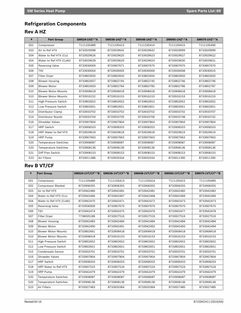
Spare Parts List | 69SM Series Heat Pump
8733942411 (2016/04)Revised 04-16
Refrigeration ComponentsRev A HZ
Rev B VT/CF
# Part Group SM024-1HZ*-*A SM036-1HZ*-*A SM048-1HZ*-*A SM060-1HZ*-*A SM070-1HZ*-*A
S01 Compressor T111105489 T111105413 T111105414 T111105415 T111105490
S03 Air to Ref HTX 8733929998 8733929642 8733929642 8733929999 8733929999
S04 Water to Ref HTX (Cu) 8733929626 8733929625 8733929623 8733929627 8733929622
S04 Water to Ref HTX (CuNi) 8733929628 8733929629 8733929624 8733929630 8733929631
S05 Reversing Valve 8733930009 8733907671 8733907670 8733907670 8733907670
S06 TXV 8733930004 8733930005 8733930006 8733930008 8733930010
S07 Filter Dryer 8733802650 8733802650 8733802650 8733802650 8733802650
S08 Blower Housing 8733802657 8733802745 8733802745 8733802746 8733802746
S09 Blower Motor 8733802693 8733802784 8733802785 8733802786 8733802787
S10 Blower Motor Mounts 8733908418 8733908418 8733908418 8733908418 8733908418
S10 Blower Motor Mounts 8733916152 8733916153 8733916153 8733916153 8733916153
S11 High Pressure Switch 8733802652 8733802652 8733802652 8733802652 8733802652
S12 Low Pressure Switch 8733802651 8733802651 8733802651 8733802651 8733802651
S14 Distributor Clamp 8733933702 8733933702 8733933702 8733933742 8733933707
S14 Distributor Nozzle 8733933704 8733933705 8733933706 8733933748 8733933742
S16 Shredder Valves 8733907804 8733907804 8733907804 8733907804 8733907804
S17 HRP Switch 8733908203 8733908203 8733908203 8733908203 8733908203
S18 HRP Water to Ref HTX 8733929618 8733929618 8733929618 8733929619 8733929619
S19 HRP Pump 8733907663 8733907663 8733907663 8733907663 8733907663
S20 Temperature Switches 8733908087 8733908087 8733908087 8733908087 8733908087
S20 Temperature Switches 8733908136 8733908136 8733908136 8733908136 8733908136
S21 Diff Pres Switch 8733908153 8733908153 8733908153 8733908153 8733908153
S23 Air Filters 8733911386 8733920334 8733920334 8733911390 8733911390
# Part Group SM024-1VT/CF*-*B SM036-1VT/CF*-*B SM048-1VT/CF*-*B SM060-1VT/CF*-*B SM070-1VT/CF*-*B
S01 Compressor T111105489 T111105413 T111105414 T111105415 T111105490
S02 Compressor Blanket 8733906355 8733906355 8733906355 8733906355 8733906355
S03 Air to Ref HTX 8733942480 8733942481 8733942481 8733942482 8733942482
S04 Water to Ref HTX (Cu) 8733942466 8733942467 8733942468 8733942469 8733942469
S04 Water to Ref HTX (CuNi) 8733942470 8733942471 8733942472 8733942473 8733942473
S05 Reversing Valve 8733930009 8733907670 8733907670 8733907670 8733907670
S06 TXV 8733942474 8733942475 8733942476 8733942477 8733942478
S07 Filter Dryer 7738005186 8733927516 8733927516 8733927516 8733927516
S08 Blower Housing 8733942483 8733942484 8733942484 8733942484 8733942484
S09 Blower Motor 8733942490 8733942491 8733942492 8733942493 8733942494
S10 Blower Motor Mounts 8733802661 8733908418 8733908418 8733908418 8733908418
S10 Blower Motor Mounts 8733908418 8733916153 8733916153 8733916153 8733916153
S11 High Pressure Switch 8733802652 8733802652 8733802652 8733802652 8733802652
S12 Low Pressure Switch 8733802651 8733802651 8733802651 8733802651 8733802651
S15 Condensate Sensor 8733933701 8733933701 8733933701 8733933701 8733933701
S16 Shraeder Valves 8733907804 8733907804 8733907804 8733907804 8733907804
S17 HRP Switch 8733908203 8733908203 8733908203 8733908203 8733908203
S18 HRP Water to Ref HTX 8733907523 8733907524 8733907524 8733907524 8733907524
S19 HRP Pump 8733942479 8733942479 8733942479 8733942479 8733942479
S20 Temperature Switches 8733908087 8733908087 8733908087 8733908087 8733908087
S20 Temperature Switches 8733908136 8733908136 8733908136 8733908136 8733908136
S23 Air Filters 8733927483 8733920364 8733920364 8733927485 8733927485

SM Series Heat Pump
SM Series Heat Pump8733942411 (2016/04) Subject to change without prior notice
70 | Exploded Views
EXPLODED VIEWS
Figure # 72

Exploded Views | 71SM Series Heat Pump
8733942411 (2016/04)Revised 04-16
VT
Figure # 73

SM Series Heat Pump
SM Series Heat Pump8733942411 (2016/04) Subject to change without prior notice
72 | Exploded Views
CF
Figure # 74

Exploded Views | 73SM Series Heat Pump
8733942411 (2016/04)Revised 04-16
HZ
Figure # 75

SM Series Heat Pump
SM Series Heat Pump8733942411 (2016/04) Subject to change without prior notice
74 | Notes
NOTES

Notes | 75SM Series Heat Pump
8733942411 (2016/04)Revised 04-16

555 N.W. 65th Court, Ft. Lauderdale, FL 33309Phone: 866-642-3198 | Fax: 954-776-5529www.bosch-climate.usRevised 04/16