SM-800.6511 HE2 Controlair - aventics.com · SM-800.6511 INSTALLATION! Do not attempt to install,...
18
WARNING: INSTALLATION & MOUNTING The user of these devices must conform to all applicable electrical, mechanical, piping and other codes in the installation, operation or repair of these devices. HE - 2 TYPE CONTROLAIR ® VALVE Service Information FIG. 1 EXTERIOR VIEW SM-800.6511 INSTALLATION! Do not attempt to install, operate or repair these devices without proper training in the technique of working on pneu- matic or hydraulic systems and devices, unless under trained supervi- sion. Compressed air and hydraulic systems contain high levels of stored energy. Do not attempt to connect, disconnect or repair these products when a system is under pressure. Always exhaust or drain the pressure from a system before performing any service work. Failure to do so can result in serious personal injury. MOUNTING! Devices should be mounted and positioned in such a manner that they cannot be accidentally operated. PRESSURE vs. LEVER TRAVEL OFF CLUTCH FULL TRAVEL DESCRIPTION OF MODELS The HE-2 type CONTROLAIR Valves are handle operated units consisting of one 3-way directional side valve, and a 3-way pressure graduating portion. The directional side valve is arranged to supply inlet pressure to a separate delivery line. The pressure graduating portion is arranged to increase, decrease, or maintain graduated air pressure to a second separate delivery line. In "off" position both delivery lines are exhausted. Handle movement from "off" position actuates the graduating pressure to a delivery line. The first 10 degrees of handle travel from "off" position to "clutch" position opens the side valve to direct inlet supply pressure to a second delivery line. Further movement of handle past 10 degrees to full travel position, or 92 degrees, continues to activate the pressure graduating valve to deliver graduated pressure which increases in proportion to the amount of handle movement from neutral. The maximum pressure obtained at full handle travel depends on the value of the control spring installed. MODELS There are three models identical in function, but different in handle operating charactistics. HE-2-X CONTROLAIR Valve - Handle is spring returned to the “clutch” or off position from all other positions in the handle travel arc, EXCEPT Part No. R434002110 (P -062026-00001) which returns han- dle to “off” position from all other positions. WARNING: The possi- bility of handle returning to “off” position does exist in all HE-2-X mod- els in positions from clutch through full travel position when released. HE-2-LX CONTROLAIR Valve - Handle is spring returned to “clutch” or “off” position from all other positions in handle travel arc, EXCEPT there is mechanical detent to handle the handle at the maximum pressure position. TABLE OF CONTENTS PAGE Description of Models……………………………………….1 Graphical Symbols…………………………………………..1 Technical Data……………………………………………….2 Installation…………………………………………………….2 Maintenance and Repair……………………………………2 Outline Dimensions………………………………………….3 Description of Operation……………………………….4 & 5 Identity Schedule……………………………………….6 & 7 Exploded Views……………………………………………. 8 Parts List……………………………………………………. 9 Assembly Section Views…………………………….10 & 11 Repair Kit List……………………………………………….12 Maintenance and Repair Instructions…………………… 13 Adjustment and Testing Adjustments: Graduated Output Adjustment……………………..13 Preload Setting Adjustment………………………..13 Cam Dog Adjustment……………………………….13 Side Lever Adjustment……………………………...13 Friction Brake Adjustment………………………….13 Testing: Function……………………………………………...14 Pressure Range……………………………………..14 Leakage……………………………………………..14 Flow Capacity………………………………………14 Response……………………………………………14 Mechanical Detent………………………………….14 Test Setup………………………………………………15 Warnings and Warranties………………………………….16 WARNING! Increased friction due to dirt and wear may caused handle not to return to clutch position from lower end of travel arc. HE-2-FX CONTROLAIR Valve - Handle is equipped with a friction brake that will hold the handle in any position selected in the handle travel arc. The brake is internally adjustable.
Transcript of SM-800.6511 HE2 Controlair - aventics.com · SM-800.6511 INSTALLATION! Do not attempt to install,...

WARNING: INSTALLATION & MOUNTING
The user of these devices must conform to all applicable electrical, mechanical, piping and other codes in the installation, operation or repair of these devices.
HE - 2 TYPE CONTROLAIR® VALVE Service Information
FIG. 1 EXTERIOR VIEW
SM-800.6511
INSTALLATION! Do not attempt to install, operate or repair these devices without proper training in the technique of working on pneu-matic or hydraulic systems and devices, unless under trained supervi-sion.
Compressed air and hydraulic systems contain high levels of stored energy. Do not attempt to connect, disconnect or repair these products when a system is under pressure. Always exhaust or drain the pressure from a system before performing any service work. Failure to do so can result in serious personal injury.
MOUNTING! Devices should be mounted and positioned in such a manner that they cannot be accidentally operated.
PRESSURE vs. LEVER TRAVEL
OFF
CLUTCH FULL TRAVEL
DESCRIPTION OF MODELS
The HE-2 type CONTROLAIR Valves are handle operated units consisting of one 3-way directional side valve, and a 3-way pressure graduating portion. The directional side valve is arranged to supply inlet pressure to a separate delivery line. The pressure graduating portion is arranged to increase, decrease, or maintain graduated air pressure to a second separate delivery line.
In "off" position both delivery lines are exhausted. Handle movement from "off" position actuates the graduating pressure to a delivery line. The first 10 degrees of handle travel from "off" position to "clutch" position opens the side valve to direct inlet supply pressure to a second delivery line. Further movement of handle past 10 degrees to full travel position, or 92 degrees, continues to activate the pressure graduating valve to deliver graduated pressure which increases in proportion to the amount of handle movement from neutral. The maximum pressure obtained at full handle travel depends on the value of the control spring installed.
MODELS
There are three models identical in function, but different in handle operating charactistics.
HE-2-X CONTROLAIR Valve - Handle is spring returned to the “clutch” or off position from all other positions in the handle travel arc, EXCEPT Part No. R434002110 (P -062026-00001) which returns han-dle to “off” position from all other positions. WARNING: The possi-bility of handle returning to “off” position does exist in all HE-2-X mod-els in positions from clutch through full travel position when released.
HE-2-LX CONTROLAIR Valve - Handle is spring returned to “clutch” or “off” position from all other positions in handle travel arc, EXCEPT there is mechanical detent to handle the handle at the maximum pressure position.
TABLE OF CONTENTS PAGE
Description of Models……………………………………….1
Graphical Symbols…………………………………………..1
Technical Data……………………………………………….2
Installation…………………………………………………….2
Maintenance and Repair……………………………………2
Outline Dimensions………………………………………….3
Description of Operation……………………………….4 & 5
Identity Schedule……………………………………….6 & 7
Exploded Views……………………………………………. 8
Parts List……………………………………………………. 9
Assembly Section Views…………………………….10 & 11
Repair Kit List……………………………………………….12
Maintenance and Repair Instructions…………………… 13
Adjustment and Testing
Adjustments:
Graduated Output Adjustment……………………..13
Preload Setting Adjustment………………………..13
Cam Dog Adjustment……………………………….13
Side Lever Adjustment……………………………...13
Friction Brake Adjustment………………………….13
Testing:
Function……………………………………………...14
Pressure Range……………………………………..14
Leakage……………………………………………..14
Flow Capacity………………………………………14
Response……………………………………………14
Mechanical Detent………………………………….14
Test Setup………………………………………………15
Warnings and Warranties………………………………….16
WARNING! Increased friction due to dirt and wear may caused handle not to return to clutch position from lower end of travel arc.
HE-2-FX CONTROLAIR Valve - Handle is equipped with a friction brake that will hold the handle in any position selected in the handle travel arc. The brake is internally adjustable.

Page 2
Before installing the CONTROLAIR Valve, all air lines in the system should be blown clean to remove any moisture, dirt, or harmful contamination. Strainers are furnished in the IN-LET and OUTLET ports to protect the valve from large parti-cles of foreign matter in the line. To further ensure long, trouble-free service, a 10 MICRON or better filter should be installed in the supply line to the valve.
The HE-2 Type CONTROLAIR Valve is designed for panel mounting. The valve less pipe bracket can be installed from the top of the panel. Refer to installation view page 3 for panel opening dimensions. Allow suitable clearance for re-moval of the pipe bracket cap screws which are 2 1/8" long.
NOTE: Each valve is packaged with a mounting dimensions template.
INSTALLATION AND GENERAL MAINTENANCE
AND REPAIR RECOMMENDATIONS
Maintenance periods should be scheduled in accordance with frequency of use and working environment of the CONTROLAIR Valve.
All valves must be visually inspected for wear and given an "in system" operating performance and leakage test at least once a year. If these visual observations indicate valve repair is required, the valve must be removed, repaired and tested.
INSTALLATION
GENERAL MAINTENANCE AND REPAIR-RECOMMENDATIONS
TECHNICAL DATA:
MAXIMUM OPERATING PRESSURE 200 psi (13.8 bar)
Admissible medium Air, clean and dry
Operating Temperature -40°F to +160°F (-40°C to 71°C)
Hysteresis 1 ½ psi (.10 bar)
Control Pressure Range (Ref. Identity Chart, Page 6
Pressure Change ½ psi (.03 bar) increment
Mounting Flange Plate
Port Size ½ - 18 NPTF
Materials
Controlair Valve
Housing and Body Die cast aluminum
Internal Parts Brass, rubber (buna-N), aluminum, steel, plastic &
hytrel inlet valve assemblies
Weight 9 lbs. (4 kg) approximately
A major overhaul is recommended at one million cycles. However, where frequency of use is such that it would require more than two years to obtain one million cycles, the valve must be overhauled at the two year period.
When it is determined that the CONTROLAIR Valve requires a major repair as a result of the one million cycles, one year routine inspection, or the two year service period has elapsed, the device must be disassembled, cleaned, inspected, parts replaced as required, rebuilt and tested for leakage, and proper operation prior to installation. Refer to MAJOR REPAIR AND MAINTENANCE INSTRUCTION, page 13, and TEST PROCEDURES, page 14.
One complete CONTROLAIR Valve should be kept in stock for each four valves in service. During the maintenance period, replace the complete valve with the "stand-by" unit. This will reduce production time loss and afford inspection and replacement of worn parts at a more appropriate or opportune time and favorable location.
Notice that the operating portion of a valve can be removed without disturbing the pipe connections Remove the valve from the pipe bracket by loosening four (4) screws and lift the unit free.
No special tools are required to maintain the CONTROLAIR Valve, with exception of internal snap-ring pliers.
Page 3
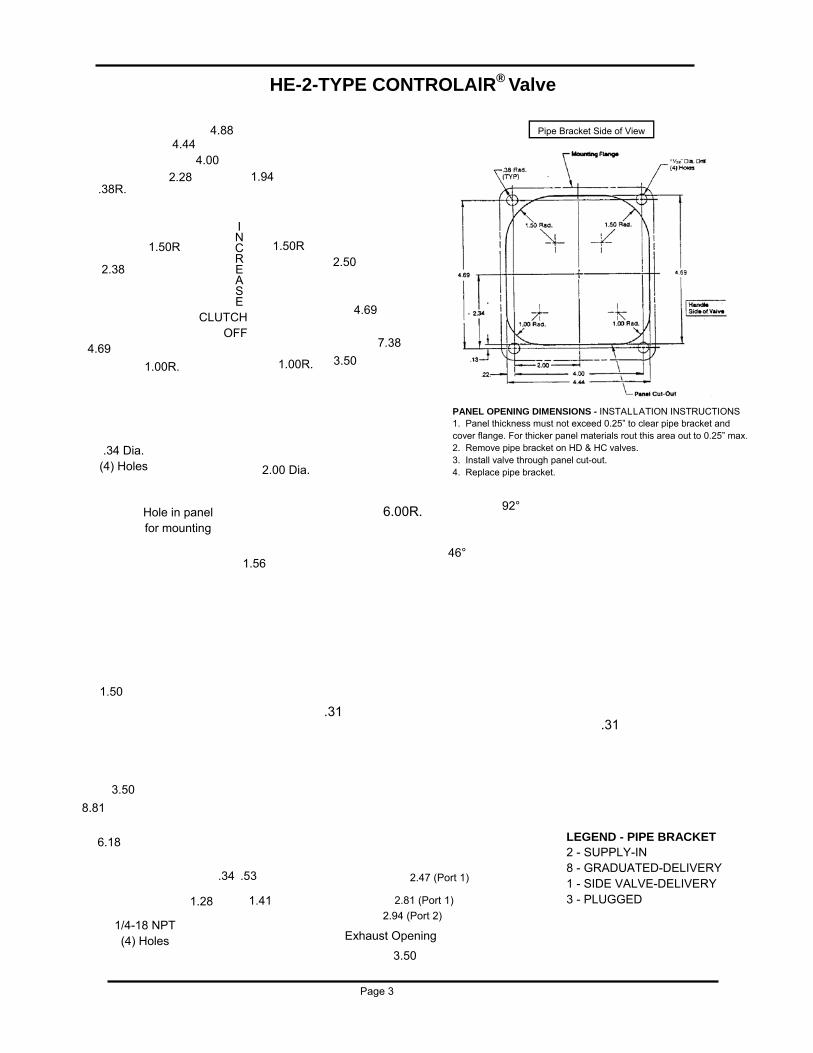
HE-2-TYPE CONTROLAlR® Valve
PANEL OPENING DIMENSIONS - INSTALLATION INSTRUCTIONS 1. Panel thickness must not exceed 0.25” to clear pipe bracket and cover flange. For thicker panel materials rout this area out to 0.25” max. 2. Remove pipe bracket on HD & HC valves. 3. Install valve through panel cut-out. 4. Replace pipe bracket.
Pipe Bracket Side of View
LEGEND - PIPE BRACKET 2 - SUPPLY-IN 8 - GRADUATED-DELIVERY 1 - SIDE VALVE-DELIVERY 3 - PLUGGED
92°
46°
6.00R.
.31
2.47 (Port 1)
2.81 (Port 1)
2.94 (Port 2)
3.50
Exhaust Opening
8.81
6.18
3.50
1.50
1.56
.53 .34
1.28 1.41
1/4-18 NPT (4) Holes
4.88 4.44
4.00
2.28 1.94 .38R.
1.50R 1.50R
4.69
2.38
1.00R. 1.00R.
.34 Dia. (4) Holes
Hole in panel for mounting
2.00 Dia.
CLUTCH OFF
I N C R E A S E
3.50
7.38
4.69
2.50
.31

DESCRIPTION OF OPERATION
Note in the diagrammatic that supply pressure is connected to port (2) and this supply pressure is directed to the side control valve and the graduating pressure control valve. The cavity for a second side control valve is plugged. The delivery from the side valve is directed to port (1). The delivery from the graduating valve is directed to port (8).
With the handle is “OFF” position port (1) is open to atmosphere through its respective side valve and port (8) is at zero.
The handle operates a dual cam. The cir-cumferential surface of the cam is contoured to provide gradual positing increments to the graduat-ing control portion. A side cam surface deflects the pilot lever to operate the side valve.
Movement of the handle from “OFF”, positions the dual cam to push down the pressure control plunger closing lower exhaust valve and opening the upper supply valve which permits air to flow to port (8) and the upper diaphragm chamber. As the pressure builds up in the delivery line (8) it acts through the sensing port orifice and deflects the control diaphragm downward, compressing the control spring. When sufficient diaphragm deflec-tion is obtained to allow the upper supply valve in pressure control portion to close, the pressure in the delivery line is held to that valve.
The valve of the pressure delivered to the outlet port is proportional to the pressure control plunger movement. This movement in turn is controlled by the cam contour and is therefore proportional to the handle travel.
Movement of the handle to the first 10 de-grees of the handle travel, “clutch” position, oper-ates the 3-way side valve to connect supply “IN” pressure to outlet port (1).
The HE-2 CONTROLAIR Valve will automatically compensate for downstream air pressure changes in the graduated pressure delivery line (8). These air pressure changes can be caused by line leakage, temperature change or load feedback. If air pressure at the outlet port (8) increases over that called for by handle position, the diaphragm in the control portion will deflect downward opening the lower exhaust valve and exhausting air until the original setting is obtained. If the pressure drops below that called for by the handle position the decreased force on the diaphragm will allow the control spring to force the diaphragm upward, cracking the upper supply valve to restore the set pressure.
The range of pressure is controlled by the strength of the diaphragm spring. Various values are available as shown on Identity Schedule, page 6.
Page 4

DIAGRAMMATIC VIEW
ME-2 Controlair Valve
Valve Symbol
Exhaust Port
Adjust Screw
Range Control Spring
Exhaust Valve
Supply Valve
Inlet & Exhaust Valve Unit
LEGEND PIPE BRACKET 2 - SUPPLY-IN 8 - GRADUATED-DELIVERY 1 - SIDE VALVE-DELIVERY 3 - PLUGGED
Diaphragm
Sensing Port Orifice
Off
Dual Cam
Clutch
Full Travel
Side Valve (3-Way)
Adjusting Screw
Page 5

Model New
Part No.
Old
Part No.
Control Pressure
Range (PSI)
New Control
Spring P/N
Old Control
Spring P/N
New Cam
Portion P/N
Old Cam
Portion P/N
New Valve
Portion P/N
Old Valve
Portion P/N
Remarks
HE-2-X
R431002937 P -051692-00001
0-65 R431003732 P -05542-00000 R431002940 P -051694-00000
R4313843 P -05584-00001
R431002938 P -051692-00002
0-100 R431000043 -526749-00000 R431002940 P -051694-00000
R431003843 P -055584-00002
R431002939 P -051692-00003
0-125 R431000099 -540577-00000 R431000099 P -051694-00000
R431003844 P -055584-00003
R431002110 P -062026-00001
0-65 R431003732 P -055442-00000
R431002941 P -051694-00001
R431003842 P -055584-00001
Note 1
HE-2-LX
R431002916 P -051614-00001
0-65 R431003732 P -055442-00000
R431002920 P -051622-00000
R431003842 P -055584-00001
R431002917 P -051614-00002
0-100 R431000043 -526749-00000 R431002920 P -051622-00000
R431003843 P -055584-00002
R431002918 P -051614-00003
0-125 R431000099 -540577-00000 R431002920 P -051622-00000
R431003844 P -055584-00003
R431002912 P -051612-00001
0-65 R431003732 P -055442-00000
R431002919 P -051621-00000
R431003842 P -055584-00001
R431002913 P -051612-00002
0-100 R431000043 -526749-00000 R431002919 P -051621-00000
R431003843 P -055584-00002
R431002914 P -051612-00003
0-125 R431000099 -540577-00000 R431002919 P -051621-00000
R431003844 P -055584-00003
R431002915 P -051612-00004
0-150 R431003731 P -055441-00000
R431002919 P -051621-00000
R431003845 P -055584-00004
--- P -064001-00001
0-65 R431003732 P -055442-00000
R431002919 P -051621`-00000
R431003842 P -055584-00001
NOTE 2
R434001213 P -066625-00001
0-65 R431003732 P -055442-00000
R431006851 P -066626-00000
R431003842 P -055584-00001
NOTE 3
R434001241 P -066625-00002
0-100 R431000043 -526749-00000 R431006851 P -066626-00000
R431003843 P -055584-00002
HE-2-FX
IDENTITY SCHEDULE
NOTE 1 - Same as R431002937 (P -051692-00001) except handle returns to “off” position from any handle position.
NOTE 2 - Same as R431002912 (P -051612-00001) except external surfaces painted w/black epoxy paint.
NOTE 3 - Same as R431002912 (P -051612-00001) except Items 43, 52, & 53 are chrome plated (refer to Page 7)
*Cam Portion - less Control Portion, Pipe Bracket, Screws R431002440 (P -049902-00048) and Nameplate with Drive Screws. **Valve Portion Complete, less Pipe Bracket and Mounting Screws & Cam Portion.
(See Pages 7,8, and 9 For Item Numbers and Parts Description)
Page 6
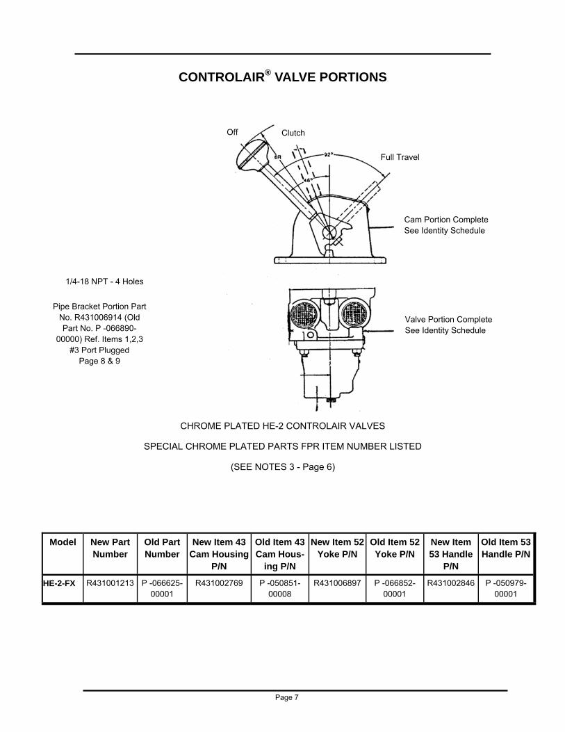
CONTROLAIR® VALVE PORTIONS
Off Clutch
Full Travel
Cam Portion Complete See Identity Schedule
Valve Portion Complete See Identity Schedule
1/4-18 NPT - 4 Holes
Pipe Bracket Portion Part No. R431006914 (Old Part No. P -066890-
00000) Ref. Items 1,2,3 #3 Port Plugged
Page 8 & 9
CHROME PLATED HE-2 CONTROLAIR VALVES
SPECIAL CHROME PLATED PARTS FPR ITEM NUMBER LISTED
(SEE NOTES 3 - Page 6)
Model New Part Number
Old Part Number
New Item 43 Cam Housing
P/N
Old Item 43 Cam Hous-
ing P/N
New Item 52 Yoke P/N
Old Item 52 Yoke P/N
New Item 53 Handle
P/N
HE-2-FX R431001213 P -066625-00001
R431002769 P -050851-00008
R431006897 P -066852-00001
R431002846
Old Item 53 Handle P/N
P -050979-00001
Page 7
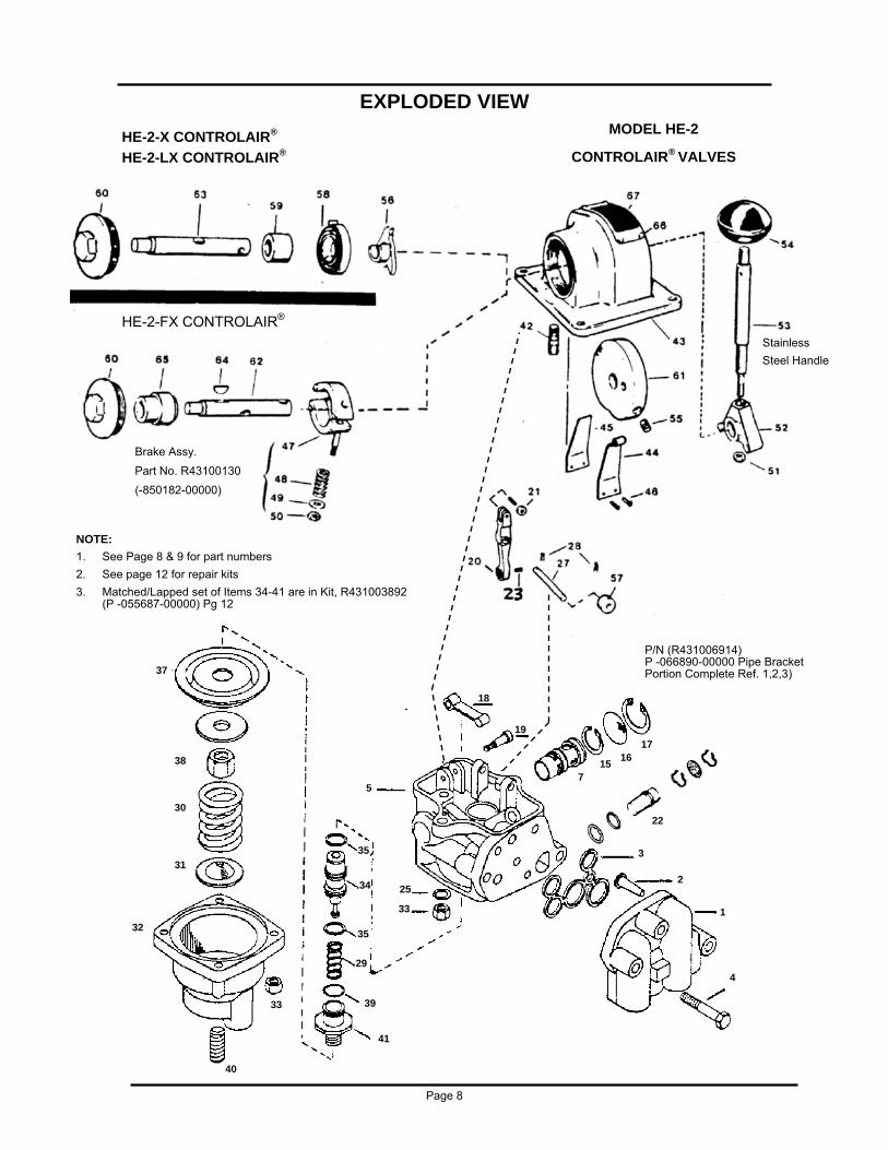
EXPLODED VIEW
Page 8
MODEL HE-2
CONTROLAIR® VALVES HE-2-X CONTROLAIR®
HE-2-LX CONTROLAIR®
HE-2-FX CONTROLAIR®
Stainless
Steel Handle
P/N (R431006914) P -066890-00000 Pipe Bracket Portion Complete Ref. 1,2,3)
NOTE:
1. See Page 8 & 9 for part numbers
2. See page 12 for repair kits
3. Matched/Lapped set of Items 34-41 are in Kit, R431003892 (P -055687-00000) Pg 12
Brake Assy.
Part No. R43100130
(-850182-00000)
37
38
30
31
32
33
40
41
39
29
35
34
35
33
25
5
4
1
2
3
18
7 15
16 17
22
19
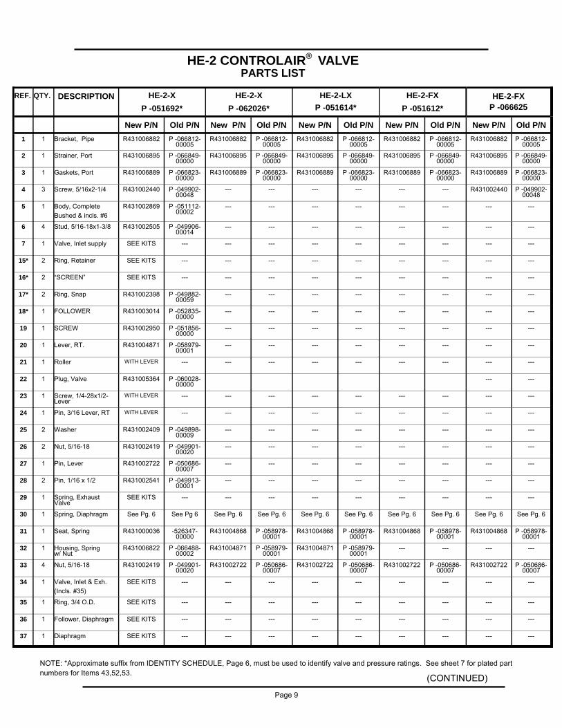
REF. QTY. DESCRIPTION HE-2-X
P -051692*
HE-2-X
P -062026*
HE-2-LX
P -051614* HE-2-FX
P -066625
New P/N Old P/N New P/N Old P/N New P/N Old P/N New P/N Old P/N New P/N Old P/N
1 1 Bracket, Pipe R431006882 P -066812-00005
R431006882 P -066812-00005
R431006882 P -066812-00005
R431006882 P -066812-00005
R431006882 P -066812-00005
2 1 Strainer, Port R431006895 P -066849-00000
R431006895 P -066849-00000
R431006895 P -066849-00000
R431006895 P -066849-00000
R431006895 P -066849-00000
3 1 Gaskets, Port R431006889 P -066823-00000
R431006889 P -066823-00000
R431006889 P -066823-00000
R431006889 P -066823-00000
R431006889 P -066823-00000
4 3 Screw, 5/16x2-1/4 R431002440 P -049902-00048
--- --- --- --- --- --- R431002440 P -049902-00048
5 1 Body, Complete
Bushed & incls. #6
R431002869 P -051112-00002
--- --- --- --- --- --- --- ---
6 4 Stud, 5/16-18x1-3/8 R431002505 P -049906-00014
--- --- --- --- --- --- --- ---
7 1 Valve, Inlet supply SEE KITS --- --- --- --- --- --- --- --- ---
15* 2 Ring, Retainer SEE KITS --- --- --- --- --- --- --- --- ---
16* 2 “SCREEN” SEE KITS --- --- --- --- --- --- --- --- ---
17* 2 Ring, Snap R431002398 P -049882-00059
--- --- --- --- --- --- --- ---
18* 1 FOLLOWER R431003014 P -052835-00000
--- --- --- --- --- --- --- ---
19 1 SCREW R431002950 P -051856-00000
--- --- --- --- --- --- --- ---
20 1 Lever, RT. R431004871 P -058979-00001
--- --- --- --- --- --- --- ---
21 1 Roller WITH LEVER --- --- --- --- --- --- --- --- ---
22 1 Plug, Valve R431005364 P -060028-00000
--- ---
23 1 Screw, 1/4-28x1/2-Lever
WITH LEVER --- --- --- --- --- --- --- --- ---
24 1 Pin, 3/16 Lever, RT WITH LEVER --- --- --- --- --- --- --- --- ---
25 2 Washer R431002409 P -049898-00009
--- --- --- --- --- --- --- ---
26 2 Nut, 5/16-18 R431002419 P -049901-00020
--- --- --- --- --- --- --- ---
27 1 Pin, Lever R431002722 P -050686-00007
--- --- --- --- --- --- --- ---
28 2 Pin, 1/16 x 1/2 R431002541 P -049913-00001
--- --- --- --- --- --- --- ---
29 1 Spring, Exhaust Valve
SEE KITS --- --- --- --- --- --- --- --- ---
30 1 Spring, Diaphragm See Pg. 6 See Pg 6 See Pg. 6 See Pg. 6 See Pg. 6 See Pg. 6 See Pg. 6 See Pg. 6 See Pg. 6 See Pg. 6
31 1 Seat, Spring R431000036 -526347-00000
R431004868 P -058978-00001
R431004868 P -058978-00001
R431004868 P -058978-00001
R431004868 P -058978-00001
32 1 Housing, Spring w/ Nut
R431006822 P -066488-00002
R431004871 P -058979-00001
R431004871 P -058979-00001
--- --- --- ---
33 4 Nut, 5/16-18 R431002419 P -049901-00020
R431002722 P -050686-00007
R431002722 P -050686-00007
R431002722 P -050686-00007
R431002722 P -050686-00007
34 1 Valve, Inlet & Exh.
(Incls. #35)
SEE KITS --- --- --- --- --- --- --- --- ---
35 1 Ring, 3/4 O.D. SEE KITS --- --- --- --- --- --- --- --- ---
36 1 Follower, Diaphragm SEE KITS --- --- --- --- --- --- --- --- ---
37 1 Diaphragm SEE KITS --- --- --- --- --- --- --- --- ---
HE-2-FX
P -051612*
HE-2 CONTROLAIR® VALVE PARTS LIST
Page 9
NOTE: *Approximate suffix from IDENTITY SCHEDULE, Page 6, must be used to identify valve and pressure ratings. See sheet 7 for plated part numbers for Items 43,52,53.
(CONTINUED)

38 1 SEE KITS --- --- --- --- --- --- ---
39 1 SEE KITS --- --- --- --- --- --- ---
40 1 R431006770 P -066209-00000
R431006770 P -066209-00000
R431002766 P -066209-00000
R431006770 P -066209-00000
41 1 SEE KITS --- --- --- --- --- --- ---
42 2 R431002505 P -049906-00014
R431002505 P -049906-00014
R431002505 P -049906-00014
R431002505 P -049906-00014
42A 1 R431002923 P -051622-00003
R431002923 P -051622-00003
R431002506 P -051622-00001
R431002923 P -051622-00003
43 1 R431002922 P -051622-00002
--- --- --- --- --- ---
44 1 SEE KITS --- --- --- --- --- --- ---
45 1 SEE KITS --- --- --- --- --- --- ---
46 2 SEE KITS --- --- --- --- --- --- ---
47 1 --- --- --- --- --- --- SEE KITS ---
48 1 --- --- --- --- --- --- SEE KITS ---
49 1 --- --- --- --- --- --- SEE KITS ---
50 1 --- --- --- --- --- --- SEE KITS ---
51 1 R431001871 P -049589-00000
--- --- --- --- --- ---
52 1 R431006896 P -066852-00000
--- --- --- --- --- ---
53 1 R431000155 -850460-00000
--- --- --- --- --- ---
54 1 R431000012 -517026-00000
--- --- --- --- --- ---
55 1 SEE KITS --- --- --- --- --- --- ---
56 1 R431000136 -850254-00000
--- --- --- --- --- ---
57 1 R431002691 P -050625-00001
--- --- --- --- --- ---
58 2 R431000137 -850256-00000
--- --- --- --- --- ---
59 1 R431000146 -850400-00000
--- --- --- --- --- ---
60 1 R431003740 P -055465-00000
--- --- --- --- --- ---
61 1 R431002928 P -051623-00003
R431005990 P -062027-00001
R431002419 P -051624-00000
R431002927 P -051623-00002
62 --- --- --- --- --- --- --- ---
63 1 R431000059 -534488-00000
--- --- --- --- --- ---
64 1 --- --- --- --- --- --- R431002109 P -049767-00003
65 1 --- --- --- --- --- --- SEE KITS ---
66 4 R431002597 P -049987-00002
R431002597 P -049987-00002
R431002597 P -049987-00002
R431002597 P -049987-00002
67 1 R431001717 P -049197-00002
R431000073 -536565-00001
R431000073 -536565-00000
R431000072 -536565-00000
Nut, 9/16-18
Ring, 11/16 - “O” Ring
Screw Spline Hex. Adj.
Seat Exhaust Valve
Screw, 5/16-18
Housing, Cam(Complete)(Incls.42,44,45,46,66, 67,68,69)
Housing Complete (Bushed)
Latch
Latch Spring
Rivet
Shoe & Holder
Spring
Washer #10
Nut, 10-32
Nut, 1/4-28 Elastic
Yoke
Shaft, Handle
Ball
Screw, 5/16-18
Arbor
Spacer
Spring
Arbor
Nut, Cap
Cam, Complete
Ring, Retaining
Shaft, Cam Complete
Key
Drum, Brake
Screw, Drive
Escutcheon Plate
---
---
R431006770
---
R431002505
R431002922
R431002769
---
---
---
---
---
---
---
---
R431006897
R431002846
---
---
---
---
---
---
---
R431002682
---
---
---
---
R431002597
R431000072
---
---
P -066209-00000
---
P -049906-00014
P -051622-00002
P -050851-00008
---
---
---
---
---
---
---
---
P -066852-00001
P -050979-00001
---
---
---
---
---
---
---
P -050600-00002
P -04987-00002
-536565-00000
REF QTY. DESCRIPTION HE-2-X
P -051692*
HE-2-X
P -062026*
HE-2-LX
P -051614*
HE-2-FX
P -051612*
New P/N Old P/N New P/N Old P/N New P/N Old P/N New P/N Old P/N New P/N Old P/N
HE-2-FX P -066625*
HE-2 CONTROLAIR® VALVE PARTS LIST (Continued)
Page 10
Page 11
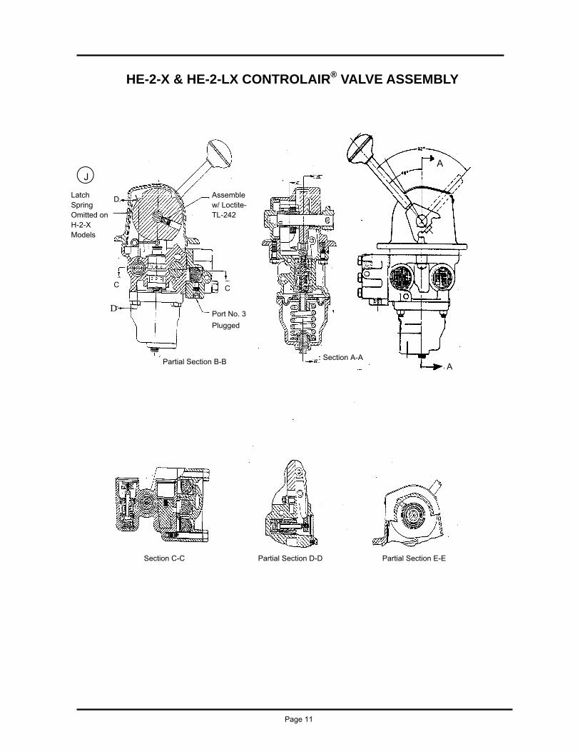
HE-2-X & HE-2-LX CONTROLAIR® VALVE ASSEMBLY
Latch Spring Omitted on H-2-X Models
Port No. 3
Plugged
A
A
Section A-A Partial Section B-B
J
Assemble w/ Loctite-TL-242
D
C
D
C
Section C-C Partial Section D-D Partial Section E-E
HE-2-FX CONTROLAIR® VALVE ASSEMBLY
A
Assemble w/ Loctite TL242
D
C
Port No. 3
Plugged
Partial Section 3-B
E B
Section A-A B
Section C-C
HE-2-FX Model Only
Friction Brake
Page12
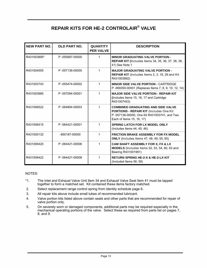
REPAIR KITS FOR HE-2 CONTROLAIR® VALVE
NEW PART NO. OLD PART NO. QUANTITY PER VALVE
DESCRIPTION
R431003895* P -055687-00000 1 MINOR GRADUATING VALVE PORTION - REPAIR KIT (Includes Items 34, 35, 36, 37, 38, 39, 41) See Note 1
R431004005 P -057136-00000 1 MAJOR GRADUATING VALVE PORTION - REPAIR KIT (Includes Items 2, 3, 18, 29 and Kit R431003892)
R431003743 P -055474-00002 1 MINOR SIDE VALVE PORTION - CARTRIDGE P -069350-00001 (Replaces Items 7, 8, 9, 10, 12, 14)
R431003985 P -057094-00001 1 MAJOR SIDE VALVE PORTION - REPAIR KIT (Includes Items 15, 16, 17 and Cartridge R431007453)
R431006522 P -064894-00003 1 COMBINED GRADUATING AND SIDE VALVE PORTIONS - REPAIR KIT (Includes One Kit P -057136-00000, One Kit R431003741, and Two Each of Items 15, 16, 17)
R431006415 P -064421-00001 1 SPRING LATCH FOR LX MODEL ONLY (Includes Items 44, 45, 46)
R431000132 -850187-00000 1 FRICTION BRAKE ASSEMBLY FOR FX MODEL ONLY (Includes Items 47, 48, 49, 50, 65)
R431006420 P -064421-00006 1 CAM SHAFT ASSEMBLY FOR X, FX & LX MODELS (Includes Items 52, 53, 54, 60, 63 and Bearing R431001991)
R431006422 P -064421-00008 1 RETURN SPRING HE-2-X & HE-2-LX KIT (Included Items 56, 58)
NOTES:
*1. The Inlet and Exhaust Valve Unit Item 34 and Exhaust Valve Seat Item 41 must be lapped together to form a matched set. Kit contained these items factory matched.
2. Select replacement range control spring from identity schedule page 6.
3. All repair kits above include small tubes of recommended lubricant.
4. Valve portion kits listed above contain seals and other parts that are recommended for repair of valve portion only.
5. On severely worn or damaged components, additional parts may be required especially in the mechanical operating portions of the valve. Select these as required from parts list on pages 7, 8, and 9.
Page 13

MAJOR REPAIR AND MAINTENANCE
ADJUSTMENTS MAJOR REPAIR AND MAINTENANCE INSTRUTION
When it is determined that the CONTROLAIR® Valve requires shop repairs (see page 2 for GENERAL MAINTENANCE AND REPAIR RECOMMENDTIONS) the following general instruc-tions are recommended:
DIASSEMBLY, CLEANING, AND LUBRICATION
Completely disassemble the CONTROLAIR® Valve. Wash all metal parts in a non-flammable solvent. Rinse each part thor-oughly and blow dry with a low pressure air jet. Arrange the parts on a clean surface.
Inspect and clear screens, Items 2 & 16. Be sure all body and bracket passages are clear and unrestricted. Be sure sensing port orifice in top of diaphragm chamber is clear.
The cam set screw, Item 55, is locktighted or nylock type. An impact wrench (set soft) will usually break it loose to remove the cam and shaft.
Examine each part carefully. Replace all rubber parts and all other worn or damaged parts. The use of REPAIR KITS is strongly recommended, see page 13.
REASSEMBLY
Refer to Exploded Parts and Assembly Views, pages 8, 11, 12.
Valve should be reassembled using new rubber parts and parts indicated by Inspection.
As reassembly proceeds, lubricate all metal-to-metal wear sur-faces with 107 Lubriplate Grease. Lubricate all rubber parts, except diaphragm with No. 55 Dow Corning Pneumatic Grease. Do not lubricate diaphragm.
The exhaust valve and seat may have to be slightly polished for minimum leakage. If necessary, use BW valve lapping com-pound (600+ grit)
The cam set screw, Item 55, must be fully seated into the drill point location provided in the shaft, Item 62 or 63. Assemble set screw, Item 55, with Loctite TL242.
Seat handle, Item 53, firmly into yoke threads before installing the nut, Item 51.
Do not over torque the cap nut, Item 60.
ADJUSTMENTS AND TEST SET UP
The valve is factory set to provide the appropriate gradu-ated pressure and mechanical operation per part number (see Identity Schedule, page 6).
However, after the CONTROLAIR has been disassem-bled, repaired and reassembled it must be adjusted and tested for proper operation prior to returning to service.
It is recommended that the valve should be connected in a test set up as shown on page 16.
ADJUSTMENTS
Screw (4) varies the graduated output pressure setting. Screw (23) adjusts the opening of the side valve, and screw (19) aligns the follower (18) with cam (61). In the HE-2-FX models, nut (50) adjusts the brake tension.
GRADUATED OUTPUT PRESSURE SETTING ADJUSTMENT
Adjusting screw (40) varies the maximum pressure setting. Turning the adjusting screw in raises the maximum pressure, turning it out decreases the maximum pressure. The maximum control pressure adjustment should not exceed the maximum control pressure shown in Identity Schedule, page 6, for part number (control springs are color coded).
The maximum output pressure rating can be changed only be changing the control spring (30). These springs are interchangeable (see Identity Schedule, page 6).
With air supplied to the valve, move handle from “OFF” to full travel position and hold. Adjust graduating valve adjusting screw (40) to obtain the maximum specified delivery pressure per Identity Schedule. Move handle back to “OFF” position and note delivery line is exhausted to zero. Repeat test to check maximum delivery pressure setting.
SIDE VALVE LEVER ADJUSTMENT
With air supplied to the valve, turn adjusting screw (4) until control spring (30) is slightly compressed. Remove snap ring (17) and screen (16). Move the CONTROLAIR Valve handle (53) back and forth observing the action of lever (20). The side valve should be fully open after the handle moves through the first 10 degrees travel arc (clutch position). Place the handle in the maximum increasing pressure position. With a 3/32” Allen Wrench, backout adjusting screw (23) of the operated lever (20) just far enough to crack the exhaust valve so that gauge will show a drop in pressure. From this point, turn the adjusting screw in a full three (3) turns. This will open the inlet valve of the side valve to its maximum capacity.
CAM DOG ADJUSTMENT
The eccentric cam dog screw (19) aligns the cam followers (18) with the rise of cam (61). Minor adjustment to graduated pressure from delivery line (8) can be made by turning the follower eccentric screw (19) either clockwise or counterclockwise. This adjustment is accessible from the outside of the valve through a notch under the panel using a long flat bladed screwdriver, cam follower screw (19).
FRICTION BRAKE ADJUSTMENT
The handle force of the HE-2-FX CONTROLAIR Valve can be varied by adjusting nut (50) on brake shoe holder (47). This adjustment increases or decreases the force required to more the handle in any position of the handle travel.
This adjustment is normally made on cam housing portion before assembly to control portion.
Page 14
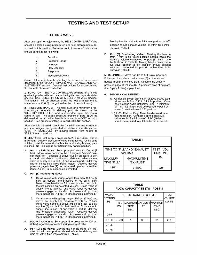
TESTING VALVE
After any repair or adjustment, the HE-2 CONTROLAIR® Valve should be tested using procedures and test arrangements de-scribed in this section. Pressure control valves of this nature should be tested for following:
1. Function 2. Pressure Range 3. Leakage 4. Flow Capacity 5. Response
6. Mechanical Detent
Some of the adjustments affecting these factors have been described in the ‘MAJOR REPAIRS MAINTENANCE AND AD-JUSTMENTS” section. General instructions for accomplishing the six tests above are as follows:
1. FUNCTION: The H-2 CONTROLAIR consists of a 3-way graduating valve with each valve having its own separate deliv-ery line. See “DESCRIPTION OF MODELS” for valve function. The function will be checked using the test arrangement to insure volume (1 & 8) charged in direction of handle travel.)
2. PRESSURE RANGE: The maximum and minimum pres-sure range generated in delivery port (8) shown on the “IDENTITY SCHEDULE”, and is dependent upon the control spring in use. The supply pressure present at port (2) will be delivered at port (1) when handle is moved from “OF” to clutch position. See pressure setting in ’ADJUSTMENT” section.
After valve is adjusted, check the 2+ minimum and maximum pressure ranges are generated in delivery line (8) as per ‘IDENTITY SCHEDULE” by moving handle from neutral to “FULL” travel position.
3. LEAKAGE: Set supply pressure to 20 psi (1.4 bar) above maximum delivery pressure of valve being tested. Using soap solution, coat the valve at pipe bracket and spring housing part-ing lines. No leakage is permitted in any handle position.
A. Port (1) Side Valve: Set supply pressure to 100 psi (7 bar). Move valve handle to the 10 degrees “clutch” posi-tion from “off” position to deliver supply pressure to port (1) and hold (detent position on detented valves); close valve in supply line to port (2) and valve in port (1) delivery line to isolate side valve being tested. Observe delivery pressure gage in line (1). A pressure drop of no more than 2 psi (.14 bar) in 30 seconds is permitted.
C. Port (8) Graduating Valve:
1. On all valves with spring ranges less than 100 psi (7 bar), set supply line pressure to 100 psi (7 bar). Move valve handle to full travel position and hold (detent position on detented valves). Close valve in supply line to port (2) and valve. Observe delivery pressure gage in line (8). A pressure drop of no more than 2 psi (.14 bar) in 30 seconds is permitted.
2. On all valves with spring ranges 100 psi (7 bar) and above, set supply line pressure to 100 psi (7 bar). Move valve handle to deliver 95 psi (6.5 bar) to deliv ery line (8) and hold in that position. Close valve in supply line to port (2) and valve in port (8) delivery line to isolate graduating valve. Observe delivery pressure gage in line (8). A pressure drop of no more than 2 psi (.14 bar) in 30 seconds is permitted.
4. FLOW CAPACITY: Set supply line pressure to 100 psi (7 bar) regardless of control spring rating of valve.
A. Port (1) Side Valve: Moving the handle from “ off” po-sition to full travel position should inflate the delivery vol-ume (1) within time limits shown in Table I.
TESTING AND TEST SET-UP
Moving handle quickly from full travel position to “off” position should exhaust volume (1) within time limits shown in Table I.
B. Port (8) Graduating Valve: Moving the handle from “off” to full travel position should inflate the delivery volume connected to port (8) within time limits shown in Table II. Moving handle quickly from full travel position to “off” position should exhaust volume connected to port (8) within time limits shown in Table II.
5. RESPONSE: Move handle to full travel position. Fully open the valve at test volume (8) so that air ex-hausts through the choke plug. Observe the delivery pressure gage at volume (8). A pressure drop of no more than 3 psi (.21 bar) is permitted.
6. MECHANICAL DETENT:
A. All models except part no. P -062062-00000 type. Move handle from “off” to “clutch” position. Con-nect a spring scale just below knob. A minimum of 7 lbf. (9.5 Nm) should be required to pull from “clutch” position toward “off” position.
B. (HE-2-LX Model Only) Move handle to extreme detent position. Connect a spring scale just below knob. A minimum of 12 lbf. (16 Nm) should be required to pull handle our of detent.
TABLE I
TEST VOL-UME CU.
IN. MAXIMUM TIME “FILL”
MAXIMUM TIME “EXHAUST”
1 SEC. 3 SEC. 225
TIME TO “FILL” AND “EXHAUST” VOLUME
TABLE II FLOW CAPACITY TESTS - POST 8
VALVE SETTING
-PSI-
TESTS RANGES & TIME
FILL PSI
MAXIMUM TIME SEC.
EXHAUST PSI
MAXIMUM TIME SEC.
0-65
0-100 0→50 1 50→10 2 225
0-125
0-150
TEST VOLUME CU. IN.
Page 15

NOTES:
1. TASKMASTER timing volume, part number R434002899 (TM-005887-00225), can be used for the volumes indicated.
2. The supply air lines to the valves and delivery lines must be full size as shown. Line length must not exceed 3 ft. (1 meter) between the supply valve and port (2), or between ports (1), and (8), and the test volume. The piping connections must have zero leakage, and must not restrict the flow. If quick couplers are used be sure they are full flow or oversize.
3. It is recommended that as large a gage as practical be used on the delivery lines. A 6” gage is recommended.
HE-2 TEST ARRANGEMENT DIAGRAM
Page 16
LEGEND-PIPE BRACKET 2 - SUPPLY-IN 8 - GRADUATED-DELIVERY 1 - SIDE VALVE-DELIVERY 3 - PLUGGED
1. WARNING: FLUID MEDIA AVENTICS pneumatic devices are designed and tested for use with filtered, clean, dry, chemical free air at pressures and tem-peratures within the specified limits of the device. For use with media other than air or for human life support systems, AVEN-TICS must be consulted. Hydraulic cylinders are designed for operation with filtered, clean, petroleum based hydraulic fluid; operation using fire-resistant or other special types of fluids may require special packing and seals. Consult the factory. 2. WARNING: MATERIAL COMPATIBILITY Damage to product seals or other parts caused by the use of noncompatible lubricants, oil additives or synthetic lubricants in the air system compressor or line lubrication devices voids AVENTICS warranty and can result in product failure or other mal-function. See lubrication recommendations below. AIR LINE LUBRICANTS! In service higher than 18 cycles per minute or with continuous flow of air through the device, an air line lubricator is recommended.* (Do not use line lubrication with vac-uum products.) However, the lubricator must be maintained since the oil will wash out the grease, and lack of lubrication will greatly shorten the life expectancy. The oils used in the lubrica-tor must be compatible with the elastomers in the device. The elastomers are normally BUNA-N, NEOPRENE, VITON, SILI-CONE and HYTREL. AVENTICS recommends the use of only petroleum based oils without synthetic additives, and with an aniline point between 180· F and 210· F. COMPRESSOR LUBRICANTS! All compressors (with the excep-tion of special "oil free" units) pass oil mist or vapor from the inter-nal crankcase lubricating system through to the com-pressed air. Since even small amounts of non-compatible lubri-cants can cause severe seal deterioration (which could result in component and system failure) special care should be taken in selecting compati-ble compressor lubricants. 3. WARNING: INSTALLATION AND MOUNTING The user of these devices must conform to all applicable electri-cal, mechanical, piping and other codes in the installation, opera-tion or repair of these devices.
NOTICE TO PRODUCT USERS
INSTALLATION ! Do not attempt to install, operate or re-pair these devices without proper training in the technique of working on pneumatic or hydraulic systems and devices, un-less under trained supervision. Compressed air and hydraulic systems con-tain high levels of stored energy. Do not attempt to connect, dis-connect or repair these products when a sys-tem is under pres-sure. Always exhaust or drain the pressure from a system before performing any service work. Failure to do so can result in seri-ous personal injury. MOUNTING! Devices should be mounted and positioned in such a manner that they cannot be accidentally operated. 4. WARNING: APPLICATION AND USE OF PRODUCTS The possibility does exist for any device or accessory to fail to operate properly through misuse, wear or malfunction. The user must consider these possibilities and should provide ap-propriate safe guards in the application or system design to prevent per-sonal injury or property damage in the event of a malfunction. 5. WARNING: CONVERSION, MAINTENANCE AND REPAIR When a device is disassembled for conversion to a different con-figuration, maintenance or repair, the device must be test-ed for leakage and proper operation after being reassembled and prior to installation. MAINTENANCE AND REPAIR! Maintenance periods should be scheduled in accordance with frequency of use and working con-ditions. All AVENTICS products should provide a minimum of 1,000,000 cycles of maintenance free service when used and lubricated as recommended. However, these products should be visually inspected for defects and given an "in system" operating performance and leakage test once a year. Where devices re-quire a major repair as a result of the one million cycles, one year, or routine inspection, the device must be disassembled, cleaned, inspected, parts replaced as required, rebuilt and tested for leakage and proper operation prior to installation. See individ-ual catalogs for specific cycle life estimates. 6. PRODUCT CHANGES Product changes including specifications, features, designs and availability are subject to change at any time without no-tice. For critical dimensions or specifications, contact factory. *Many AVENTICS pneumatic valves and cylinders can operate with or without air line lubrication; see individual sales catalogs for details.
LIMITATIONS OF WARRANTIES & REMEDIES AVENTICS warrants its products sold by it to be free from defects in material and workmanship to the following: For twelve months after shipment AVENTICS will repair or replace (F.O.B. our works), at its option, any equipment which under normal conditions of use and service proves to be defective in material or workmanship at no charge to the purchaser. No charge will be made for labor with respect to defects covered by this Warranty, provided that the work is done by AVENTICS or any of its authorized service facilities. However, this Warranty does not cover expenses incurred in the removal and reinstallation of any prod-uct, nor any downtime incurred, whether or not proved defective. All repairs and replacement parts provided under this Warranty policy will assume the identity, for warranty purposes, of the part replaced, and the warranty on such replacement parts will expire when the warranty on the original part would have expired. Claims must be submitted within thirty days of the failure or be Subject to rejection. This Warranty is not transferable beyond the first using purchaser. Specifically, excluded from this Warranty are failures caused by misuse, neglect, abuse, improper operation or filtration, extreme temperatures, or unauthorized service or parts. This Warranty also excludes the use of lubricants, fluids or air line additives that are not compatible with seals or diaphragms used in the products. This Warranty sets out the purchaser's exclusive remedies with respect to products covered by it, whether for negligence or otherwise. Neither, AVENTICS nor any of its affiliates will be liable for consequential or incidental damages or other losses or .expenses in-curred by reason of the use or sale of such products. Our liability (except as to title) arising out of the sale, use or operation of any product or parts, whether on warranty, contract or negligence (including claims for consequential or incidental damage) shalI not in any event exceed the cost of replacing the defective products and, upon expiration of the warranted period as herein provided, all such liability is terminated. THIS WARRANTY IS IN LIEU OF ALL OTHER WARRANTIES, EXPRESS OR IMPLIED, WHETHER FOR MERCHANTABILITY OR FITNESS FOR A PARTICULAR PURPOSE OR OTHERWISE. No attempt to alter, amend or extend this Warranty shall be effective unless authorized in writing by an officer of AVENTICS Corporation. AVENTICS reserves the right to discontinue manufacture of any product, or change product materials, design or specifications with-out notice.
Page 17
AVENTICS Corporation
1953 Mercer Road
Lexington, KY 40511
www.aventics.com/us
AVENTICS Incorporated
3426 Mainway Drive Burlington, Ontario CANADA L7M 1A8
www.aventics.com/ca
SM-800.6511/May 2014 Subject to change. Printed in United States. AVENTICS Corporation. This document, as well as the data, specifications, and other information set forth in it, are the exclusive property of AVENTICS. It may not be reproduced or given to third parties without its consent.