SM-6000 Series · 10 years for extreme operation. • Gearing: All steel bevel and helical gearing....
64
Keeping the World Flowing SM-6000 Series Rotary Actuators with Local Remote Switch Installation Manual
Transcript of SM-6000 Series · 10 years for extreme operation. • Gearing: All steel bevel and helical gearing....

Keeping the World Flowing
SM-6000 Series
Rotary Actuators with Local Remote Switch
Installation Manual

SM6000 Series2
Product Overview 3
1 General Information 4
2 Specifications 7
2.1 Optional Equipment 8
3 Installation 9
3.1 Typical Wiring Diagram 12
3.2 Microprocessor Based Motor 13 Drive & Controller Setup
4 Operating your SM6000 14
4.1 Status Description 16
4.2 Start Up 17
4.2.1 - Select Automatic Mode 20
4.3 Range of Operation - Setup 23
4.3.1 - Range of Operation 23
4.3.2 - Set Zero and SPAN 27
4.3.3 - Setting Limit Switches 32
4.3.4 - Operating Speed 34
5 Setup & Calibration 36
5.1 Setup & Calibration - Level 1 37
5.1.1 - Max Cmd Cal 38
5.1.2 - Min Cmd Cal 38
5.1.3 - Speed 39
5.1.4 - CMD Type 39
5.1.5 - LOS Act 39
5.1.6 - LOS Pos 40
5.1.7 - CUR P Gain 40
5.1.8 - CUR I Gain 40
5.1.9 - Min Pos 41
5.1.10 - Max Pos 41
5.1.11 - Max Torque % 42
5.1.12 - Save Config 42
5.2 Communications 43
5.2.1 - HART Control Options 43
5.2.2 - PROFIBUS Control Options 45
5.2.3 - Foundation Fieldbus 47 Control Options
5.3 Setup and Calibration - Level 2 49
5.3.1 - Motor PWM 50
5.3.2 - MAX TORQUE 50
5.3.3 - INPUT VOLT 50
5.3.4 - MOTOR RATE 50
5.3.5 - PASS ENBLD 50
5.3.5.1 - PASSWORD 50
5.3.6 - LOOP 50
5.3.7 - LOAD FACT DEFS 50
6 Faults & Troubleshooting 52
6.1 Fault Status Indication 52
6.2 Troubleshooting 53
7 Local Operation - Handcrank Direction 54
8 Mounting Conversion 55
9 Parts Identification 56
10 Drive Arm Dimensions 59
11 Overall Dimensions 60
12 Linkage Options 61
13 User Settings 62
Notes 63
Section Page Section Page
This manual contains important safety information. Please ensure it is thoroughly read and understood before installing, operating or maintaining the equipment.
Due to wide variations in the terminal numbering of actuator products, actual wiring of this device should follow the PRINT SUPPLIED with the unit.
Keeping the World Flowing 3
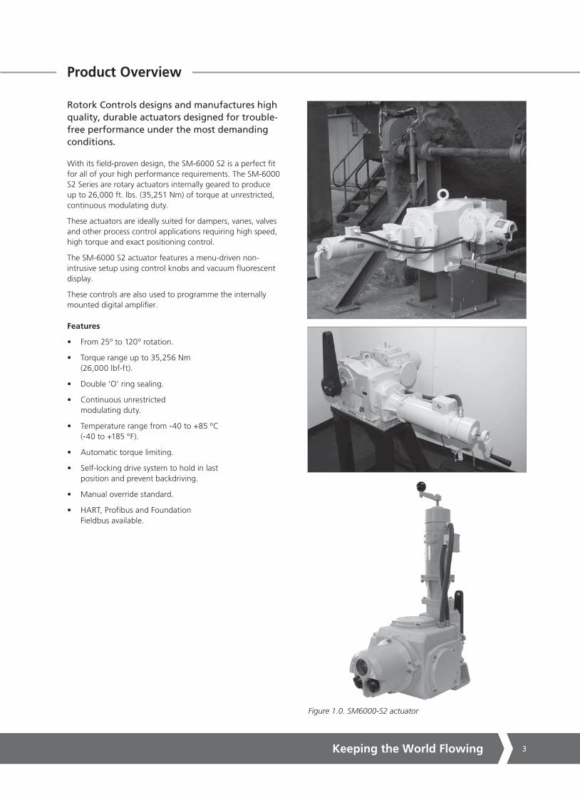
Figure 1.0. SM6000-S2 actuator
Product Overview
Rotork Controls designs and manufactures high quality, durable actuators designed for trouble-free performance under the most demanding conditions.
With its field-proven design, the SM-6000 S2 is a perfect fit for all of your high performance requirements. The SM-6000 S2 Series are rotary actuators internally geared to produce up to 26,000 ft. lbs. (35,251 Nm) of torque at unrestricted, continuous modulating duty.
These actuators are ideally suited for dampers, vanes, valves and other process control applications requiring high speed, high torque and exact positioning control.
The SM-6000 S2 actuator features a menu-driven non-intrusive setup using control knobs and vacuum fluorescent display.
These controls are also used to programme the internally mounted digital amplifier.
Features
• From 25º to 120º rotation.
• Torque range up to 35,256 Nm (26,000 lbf-ft).
• Double ‘O’ ring sealing.
• Continuous unrestricted modulating duty.
• Temperature range from -40 to +85 ºC (-40 to +185 ºF).
• Automatic torque limiting.
• Self-locking drive system to hold in last position and prevent backdriving.
• Manual override standard.
• HART, Profibus and Foundation Fieldbus available.

SM6000 Series4
INTRODUCTION
Rotork Controls designs, manufactures, and tests its products to meet national and International standards. For these products to operate within their normal specifications, they must be properly installed and maintained. The following instructions must be followed and integrated with your safety program when installing, using, and maintaining Rotork Controls products:
Read and save all instructions prior to installing, operating, and servicing this product. If any of the instructions are not understood, contact your Rotork Controls representative for clarification.
Follow all warnings, cautions, and instructions marked on, and supplied with, the product. Inform and educate personnel in the proper installation, operation, and maintenance of the product.
Install equipment as specified in Rotork Controls installation instructions and per applicable local and national codes. Connect all products to the proper electrical sources. To ensure proper performance, use qualified personnel to install, operate, update, tune, and maintain the product.
When replacement parts are required, ensure that the qualified service technician uses replacement parts specified by Rotork Controls. Substitutions may result in fire, electrical shock, other hazards, or improper equipment operation.
WARNING
Before installing the actuator, make sure that it is suitable for the intended application. If you are unsure, consult Rotork Controls prior to proceeding.
WARNING - SHOCK HAZARD
Installation and servicing must be performed only by qualified personnel.
WARNING ELECTROSTATIC DISCHARGE
This electronic control is static-sensitive. To protect the internal components from damage, never touch the printed circuit cards without using electrostatic discharge (ESD) control procedures.
RECEIVING / INSPECTION
Carefully inspect for shipping damage. Damage to the shipping carton is usually a good indication that it has received rough handling. Report all damage immediately to the freight carrier and Rotork Controls, Inc.
Unpack the product and information packet - taking care to save the shipping carton and any packing material should return be necessary. Verify that the items on the packing list or bill of lading agree with your own.
STORAGE
If the actuator will not be installed immediately, it should be stored indoors in a clean, dry area where the ambient temperature is not less than -20° F. The actuator should be stored in a non-corrosive environment. The actuator is not sealed to NEMA 4 until the conduit entries are properly connected.
1 - General Information

Keeping the World Flowing 5
1 - General Information
EQUIPMENT RETURN
A Returned Goods authorization (RG) number is required to return any equipment for repair. This must be obtained from Rotork Controls. (Telephone: 414/461-9200) The equipment must be shipped, freight prepaid, to the following address after the RG number is issued:
Rotork Controls, Inc.5607 West Douglas AvenueMilwaukee, Wisconsin 53218Attn: Service Department
To facilitate quick return and handling of your equipment, include:
1. RG Number on outside of box2. Your Company Name, Contact Name, Phone/Fax3. Address4. Repair Purchase Order Number5. Brief description of the problem
IDENTIFICATION LABEL
An identification label is attached to each actuator. When ordering parts, requesting information or service assistance, please provide all of the label information. YOU MUST SUPPLY THE SERIAL NUMBER WITH ALL ENQUIRIES.
ABBREVIATIONS USED IN THIS MANUAL
A Ampere AC Alternating Current °C Degrees Celsius CW Clockwise ACW Anti-clockwise CCW Counter-clockwise DC Direct Current °F Degrees Fahrenheit G Earth Ground Hz Hertz in. lbs Inch Pounds kg Kilogram L Line (power supply) lbs Pounds Force LVDT Linear Variable Differential Transformer mA Milliamp mfd Microfarad mm Millimeters N Newton (force) NEMA National Electrical Manufacturing Association Nm Newton Meter NPT National Pipe Thread PCB Printed Circuit Board PH Phase PL Position Limit switch RPM Revolutions per Minute SEC Second SPDT Single Pole Double Throw TL Torque Limit Switch V Volts VA Volt Amps VAC Volts AC VDC Volts DC VFD Vacuum Fluorescent Display VR Variable Resistance W Watt
Figure 1.1. Actuator identification label.

SM6000 Series6
1 - General Information
GENERAL DESCRIPTION, ACTUATOR
The SM-6000 is an AC input, DC driven electric actuator designed for high modulation service. This actuator uses a Rotork Controls locally mounted, or remotely located microprocessor- based motor drive and controller. A wide array of standard options are available for this actuator.
The SM-6000 Series actuators provide the highest speed, torque, modulation rate, and positioning accuracy of any electric actuator in the Rotork Controls product line.
With the standard control electronics, they are self-contained automatic positioning devices capable of moving the largest loads at speeds typical of electrohydraulic devices, and with an unrestricted modulation rating. These high-performance actuators are electrically controlled, self-contained, high speed, high torque devices. With essentially unlimited rotational travel, they provide a superior solution for any modern actuation application.
The SM-6000 is designed using an all steel gear train submersed in an oil bath, and conservatively rated bearings.This design assures the longest possible life while reducing the risk of costly repairs and unscheduled maintenance.
An internally mounted electronic controller converts AC power input to DC power.
The DC power is then controlled by a microprocessor based digital servo amplifier that efficiently controls speed and torque of the drive motor.
The motor drives through high efficiency helical bevel gearing that provides smooth and quiet operation at rated load indefinitely in the event of power loss or shutoff.
A holding brake at the rear of the motor will hold the full rated load in the last position until power is restored. The holding brake is always in the released state whenever power is applied to the actuator. It is an electrically released, spring set type holding brake. The brake is constantly in a stand-by mode, and does not stop the motor. The motor does the braking electrically, so there is no wear on the brake because the brake is only holding, and not stopping the load. The load is always supported by the motor, even when the command input is not changing.
A local override handcrank at the rear of the motor can be used to manually position the load when power is interrupted.
The SM-6000 is well equipped with popular standard features, and a wide variety of standard options are available to suit most applications.
Special factory supplied options and designs are also available.
Figure 1.2. SM6000-S2 actuator.
Keeping the World Flowing 7
2 - Specifications
• Rotation: 25º - 120º.
• Duty Cycle: Unlimited and unrestricted continuous duty.
• Temperature: -40 to 185 °F (-40 to 85 °C). A high temperature version to 225 °F (107 °C) is available.
• Environment Ratings: NEMA Type 4 (IP65).
• Lubrication Type: Synthetic oil bath.
• Oil Change Interval: 20 years for normal operation, 10 years for extreme operation.
• Gearing: All steel bevel and helical gearing.
• Hold on Loss of Power: Spring locking brake.
• Mounting: Conventional foot mounted.
• Anti-Condensation Heater: 120 or 240 VAC, 30 Watt with thermostat set for 110 °F (43.3 °C).
• Torque Limit: Adjustable from 1 to 200% of rated torque. Warning: continued operation of unit in excess of rated load will damage the actuator and connected equipment.
• Positioning Accuracy: 0.1% of 90°.
• Position Limit Switches: Two single pole double throw (SPDT) switches for end of travel use, rating: 20 amp, 120/240 VAC resistive load.
• Feedback: Absolute Encoder.
• Local Controls & Display: Front cover mounted control knobs and Vacuum Fluorescent Display (VFD).
• Command Signal Input: 4-20 mA, 0-5 VDC or 0-10 VDC.
• Position Transmitter: 4-20 mA transmitter used to remotely track actuator position when power is available to the actuator. Requires separate 24 VDC loop-power supply for operation.
• Terminations: Screw type terminals accepting up to #14 AWG wire.
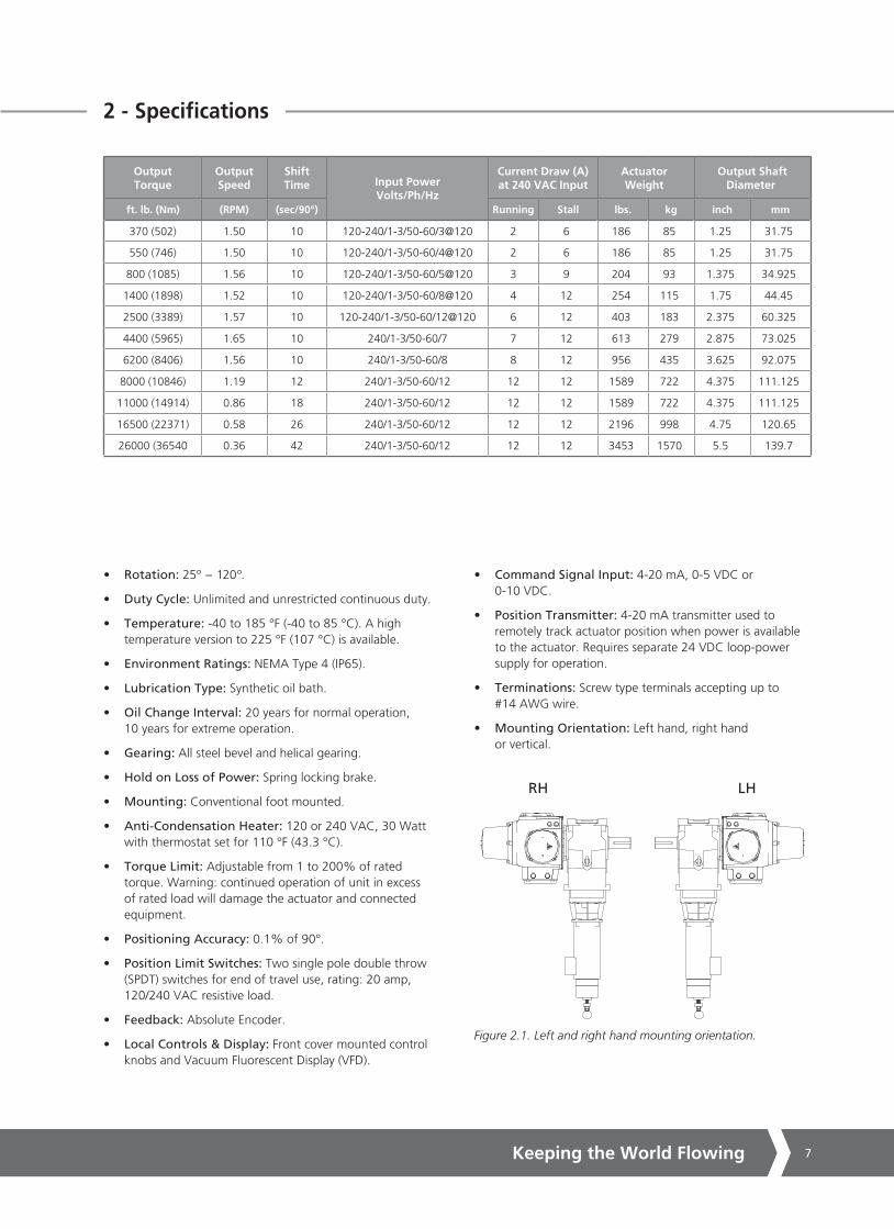
• Mounting Orientation: Left hand, right hand or vertical.
RH LH
Figure 2.1. Left and right hand mounting orientation.
OutputTorque
OutputSpeed
ShiftTime Input Power
Volts/Ph/Hz
Current Draw (A) at 240 VAC Input
Actuator Weight
Output Shaft Diameter
ft. lb. (Nm) (RPM) (sec/90°) Running Stall lbs. kg inch mm
370 (502) 1.50 10 120-240/1-3/50-60/3@120 2 6 186 85 1.25 31.75
550 (746) 1.50 10 120-240/1-3/50-60/4@120 2 6 186 85 1.25 31.75
800 (1085) 1.56 10 120-240/1-3/50-60/5@120 3 9 204 93 1.375 34.925
1400 (1898) 1.52 10 120-240/1-3/50-60/8@120 4 12 254 115 1.75 44.45
2500 (3389) 1.57 10 120-240/1-3/50-60/12@120 6 12 403 183 2.375 60.325
4400 (5965) 1.65 10 240/1-3/50-60/7 7 12 613 279 2.875 73.025
6200 (8406) 1.56 10 240/1-3/50-60/8 8 12 956 435 3.625 92.075
8000 (10846) 1.19 12 240/1-3/50-60/12 12 12 1589 722 4.375 111.125
11000 (14914) 0.86 18 240/1-3/50-60/12 12 12 1589 722 4.375 111.125
16500 (22371) 0.58 26 240/1-3/50-60/12 12 12 2196 998 4.75 120.65
26000 (36540 0.36 42 240/1-3/50-60/12 12 12 3453 1570 5.5 139.7
SM6000 Series8
2.1 - Optional Equipment
• Performance: Faster speeds are available. Consult factory.
• Drive Arm: Steel, for dimensions see section 10.
• Mechanical Stops: A plate that bolts to the front of the actuator and limits drive arm movement is available
• Relays: Customer usable relay contacts are available to detect: loss of feedback, loss of command signal, loss of power or overtorque (stall).
• Auxiliary Position Limit Switches:
20 Amp, 120/240 VAC resistive load, (Quantity, 2-4) 5 Amp, 125 VDC resistive load, (Quantity, 2-4) 3 Amp, 250 VDC resistive load, (Quantity, 2-4)
• Pluggable Connections: Pluggable connectors on the control enclosure for quick-disconnection using Cannon style connectors. Typically used for remote mounted control enclosure applications.
• Input Power: Internally mounted transformer to allow operation on other input voltages. Standard optional Input voltages are 480 VAC, 575 VAC. A 120 VA to 240 VAC step-up transformer is also available for applications using 180 VDC motors when only 120 VAC input power is available.
• Transitional Adapter Mounting Bases: Matches SM-6000 to existing actuator footprint in the field for replacement applications. Consult factory.
• High Temperature: Optional for ambient temperature to 225 °F (107 °C). Requires remote control enclosure. Other options may be limited, consult factory.
• Linkage Adapter/Clevis Kit: Used to connect drive arm to driven load for linkage applications. Includes two clevises, two adjustment rods with lock nuts, two pipe adapters, two pins for clevises.

Keeping the World Flowing 9
3 - Installation
INSTALLATION NOTES
CAUTION
READ ALL INSTRUCTIONS CAREFULLY BEFORE STARTING THE INSTALLATION IN ORDER TO ACCUSTOM YOURSELF WITH THIS EQUIPMENT. FOLLOW ALL INSTRUCTIONS DURING THE INSTALLATION. DO NOT APPLY POWER UNTIL TOLD TO DO SO OR PERMANENT DAMAGE CAN RESULT.
1. Use care whenever carrying, setting, or working around the actuator. This is a precision piece of equipment that will be permanently damaged if dropped or mistreated during handling. Damage due to abuse or mishandling is not covered by the factory warranty.
2. The installation site must have environmental conditions compatible with the actuator design. Do not use this product in temperatures higher than the design allows, or in explosive environments if it is not rated accordingly. To maintain the environmental ratings, all covers must be tightly closed at all times. All cover fittings must be used and fastened securely. Using a 3/16’’ Hex key, remove the four capscrews securing the terminal compartment cover (Fig. 3.1). The actuator is supplied with a wiring diagram, certificate of conformance and terminal fixings stored in the terminal compartment area (Fig 3.2 and Fig 3.3).
3. Read the actuator nameplate located on the outside of the unit. It will reference a specific wiring diagram. Refer to the wiring diagram to identify functions of terminals (Fig. 3.2). Check that the supply voltage is the same as that marked on the actuator nameplate. That diagram MUST be used for wiring this product. Run wires as indicated, but DO NOT apply power until later. To prevent electrical noise pickup, power and signal wires must be routed through separate metallic conduit and the signal wires must also be shielded and the shield grounded (Fig. 3.1. A,B,C,D).
For actuators where the control enclosure must be located away from the actuator, do not exceed a wire run distance of fifty feet between the actuator and the control enclosure.
When all connections are made, replace the wiring diagram in the terminal compartment.
4. Replace Terminal Cover Ensure cover o-ring seal and joint are in good condition and lightly greased before re-fitting cover. Seal any unused conduit entries with metal plugs (Fig. 3.4. C,D).
Figure 3.1. Terminal compartment cover
Figure 3.2. Terminal compartment.
Figure 3.3. Terminal fixings.
Figure 3.4.
C
C
D
D
A B

SM6000 Series10
3 - Installation cont.
5. The actuator must be securely anchored to a rigid foundation before any load is applied to the output shaft. All of the actuator mounting holes designed for anchoring must have a bolt or stud, which should be of the largest size that fits in the mounting hole (Fig. 3.5. A).
6. The drive arm (if used) should be attached to the actuator output shaft using the hardware supplied. The drive arm has a hole to attach the linkage to the load. This linkage should be connected to the drive arm with a flexible rod-end to accommodate misalignment, and the rod-end must be sized for approximately twice the actuator full load rating (Fig. 3.5. B).
7. The actuator is designed to withstand the rigors of industrial environments. To maintain the environmental ratings, all cover fixings must be used and fastened securely (Fig. 3.6).
Mounting: The outline and mounting dimensions for a standard unit are shown in this manual. Sufficient room to remove the cover should be provided for servicing and upgrade.
Orientation: The unit is oil filled and must be mounted in the configuration ordered. When mounting the unit, be sure that no excessive axial or side loading is applied to the output shaft.
Output Drive Shaft: The limit switches and position feedback are directly connected to the output shaft. Positively secure the output to the driven load shaft to prevent slippage, which would cause misalignment or damage.
Local Overide: When local override is required, push in handcrank (Fig 3.7) and turn the crank in the appropriate direction for the desired output shaft movement. Note: Do not force handcrank if there is an obstruction as excessive torque will be generated at the output shaft. The load or actuator may be damaged as a result.
CAUTION - LOCAL OPERATION
WITH RESPECT TO HAND CRANK OPERATION OF SM6000 SERIES ELECTRIC ACTUATORS, UNDER NO CIRCUMSTANCES SHOULD ANY ADDITIONAL LEVER DEVICE SUCH AS A WHEEL-KEY OR WRENCH BE APPLIED TO THE HAND CRANK MECHANISM IN ORDER TO DEVELOP MORE FORCE WHEN MOVING THE ACTUATOR IN EITHER DIRECTION AS THIS MAY CAUSE DAMAGE TO ACTUATED DEVICE, ASSOCIATED LINKAGES OR ACTUATOR ITSELF.
Figure 3.5.
Figure 3.6.
Figure 3.7.
A
B
Keeping the World Flowing 11
3 - Installation cont.
If, during local operation, electric power is restored to the actuator, the power cannot drive back through the manual handcrank and harm the operator. Upon completion of hand operation, the handcrank will spring return to its home position allowing electric operation to resume.
The handcrank and holding brake compartment at the rear of the motor relies upon the cover to maintain the watertight NEMA Type 4 rating. This cover should be removed only when work is being done internally, and should be reinstalled tightly immediately upon completion.
This unit contains no internal mechanical stops as standard. If it runs outside of the initial factory alignment of the limit switches, a realignment of switches and feedback may be required. However, no internal damage will occur.
The actuator is designed to give long, troublefree life when installed and operated in accordance with factory guidelines.
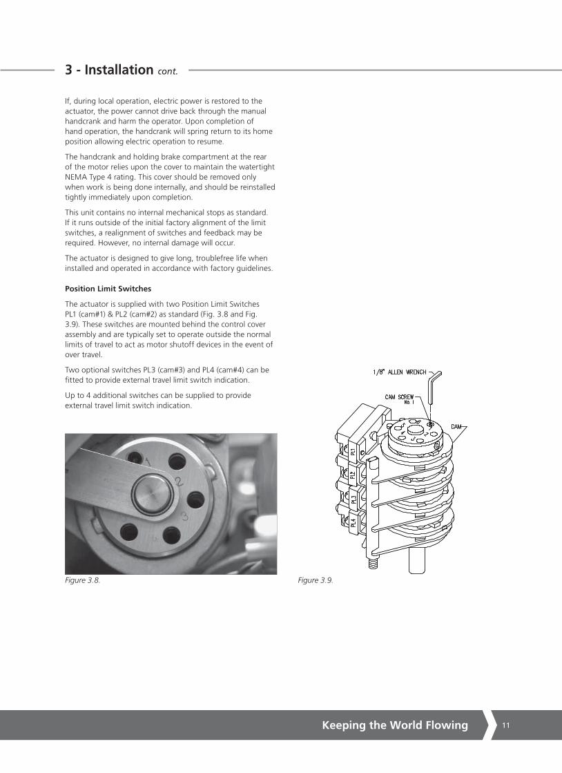
Position Limit Switches
The actuator is supplied with two Position Limit Switches PL1 (cam#1) & PL2 (cam#2) as standard (Fig. 3.8 and Fig. 3.9). These switches are mounted behind the control cover assembly and are typically set to operate outside the normal limits of travel to act as motor shutoff devices in the event of over travel.
Two optional switches PL3 (cam#3) and PL4 (cam#4) can be fitted to provide external travel limit switch indication.
Up to 4 additional switches can be supplied to provide external travel limit switch indication.
Figure 3.8. Figure 3.9.

SM6000 Series12
3.1 - Installation Wiring & Typical Wiring Diagram
A typical wiring diagram is shown below. Actual wiring should follow the print supplied with the actuator. The wiring diagram shows the fundamental connections for the standard control scheme, and standard permanent magnet DC motor. Items shown on print arrangement include limit switches, feedback potentiometers, heater and encoders. To meet special requirements, certain items shown may not be supplied. In all instances the wiring diagram appropriate to the equipment will be supplied with each unit.
Wiring should be routed to the actuator through customer supplied conduit entries located on the control enclosure. Generally, one conduit will contain input power and earth ground wires. The other conduit would then contain low level input and output signal wiring. It is required that all low level signal wiring be a shielded type with the shield grounded at source common.
After installation, it is required that all conduits be sealed to prevent water damage and to maintain watertight NEMA 4 enclosure ratings.
TYPICAL WIRING DIAGRAM
Figure 3.10. Typical SM6000-S2 Wiring Diagram
Keeping the World Flowing 13
3.2 - Microprocessor Based Motor Drive & Controller Setup
GENERAL DESCRIPTION
The microprocessor-based motor drive and controller is designed for integral local or remote mount to control appropriate Rotork Controls actuators.
A microprocessor-based control and an IGBT-based intelligent power module (IPM) are used to drive the actuator to perform highly accurate, bidirectional positioning.
The ‘Standard Setup’ is made via front cover-mounted local control knobs and a local display (VFD) on the outside of the actuator. See figure 4.2 for location of the local control knobs and display.
The ‘Alternative Setup’ feature allows actuator setup using push-buttons (no potentiometers or jumpers). See figures 4.13 and 4.14 for location of the push buttons. Self diagnostics and prompts are available through an on-board lighted display.
Specifications
• Power Input: 120/240 VAC, +/- 10%, single or three phase, 50/60 Hz.
• Power Output: Up to 90 VDC/180 VDC, 15 Amperes Peak.
• Command Inputs: 4-20 mA into 200 Ohm shunt 0-10 VDC into 100k minimum impedance or 0-5 VDC into 100k minimum Impedance.
• Position Feedback: Absolute Encoder, 1000 Ohm potentiometer (optional), 4-20 mA (optional).
NOTE: THE FACTORY DEFAULT FEEDBACK SETTINGS WERE FULLY TESTED AND INITIALLY SETUP AT THE FACTORY AND NO OTHER ADJUSTMENT OF THE ABSOLUTE ENCODER AND 1000 OHM POTENTIOMETER SHOULD BE REQUIRED.
IF ADJUSTMENTS ARE NECESSARY PLEASE CONTACT ROTORK CONTROLS.
• Position Signal Output: Loop powered, isolated, 2-wire 4-20 mA signal. Shows actuator position.
• End of Travel Position Limit Switches : Switch Cams 1 (CCW) & 2 (CW) to stop the actuator if end of travel position is exceeded.
• Position Indication Switches: (Optional) Switch cams 3 & 4 for additional position indication outputs. Up to 6 switches.
• Automatic Mode: Actuator responds to remote command input controls. Typically 4-20 mA or bus communication.
• Local Mode: Actuator responds to local pushbutton commands.
• Other Outputs: Form C fault relay output Contact Rating 120 VAC, 2 Amperes
Active when any of the following conditions are present:
• Loss of 4-20 mA command signal
• Loss of position feedback signal
• MIN/MAX limit switch reached
• Motor stalled condition
• Hand crank engaged
• Torque Limit Exceeded.

SM6000 Series14
L
R
4 - Operating your SM6000 Actuator
WARNING
Actuator may move when SPAN, ZERO or PRESET functions are selected.
Display-Local Indication
The actuator Vacuum Fluorescent Display (VFD) provides 2 x 16 Character lines to allow setup and calibration of all user parameters. The display can also be utilised to access the diagnostic menus.
Line 1 (Fig. 4.1. A).
L = Local Mode
R = Remote Control
C = Remote Communications Mode
In Local, Remote and Automatic Modes line 1 shows actuator Position and Command request in percentage of Zero - Span range.
P = Actual Position
C = Command Position
Line 2 (Fig. 4.1. B).
Act strts = Actuator starts
Provides status or fault information depending on Mode selected.
Local Control Knobs
The actuator has two control knobs located below the VFD Display window.
UP/DOWN SELECTOR KNOB (Fig. 4.2. A).
Located on left hand side as viewed from the front. Depending on mode selected different functions apply (see below).
ENTER/CANCEL KNOB (Fig. 4.2. B).
Located on right hand side as viewed from the front. Allows parameters to be changed and accepted or toggles between menus.
Local Mode
Rotate the selector knob anti-clockwise (UP) and hold to move actuator output towards the Span Position. Release when the actuator has reached the desired position.
Rotate the selector knob clockwise (Down) and hold to move actuator towards the Zero position. Release when the actuator has reached the desired position.
Setup Mode
Rotate the selector knob to the UP or DOWN position to cycle through the setup menu parameters.
L P= 100 C= 100Act Strts = 19
L P= 100 C= 100
Act Strts = 19
Figure 4.1.
Figure 4.2.
A
A
B BC

Keeping the World Flowing 15
4 - Operating your SM6000 Actuator
LOCAL/REMOTE SWITCH. (Fig. 4.2. C).
Located on the left hand side of the electrical housing as viewed from the front.
NOTE:The switch can be fitted with a padlock to prevent unauthorised operation.
LOCAL MODE
When the actuator is set to local mode It is possible to position the actuator using the UP/DOWN selector knob.
Using the ENTER/CANCEL selector knob it is possible to access and change parameters.
REMOTE MODE
Actuator will respond to remote control or communication bus card commands.

SM6000 Series16
4.1 - Status Description
STATUS DESCRIPTION
In REMOTE or Local mode Line 2 of the display shows status parameters when no faults are active.
To cycle through the menu structure select LOCAL operation.
Using the ENTER/CANCEL selector knob it is possible to access and change parameters.
Use the Enter/Cancel knob to cycle through the information (Fig. 4.4).
1 Act Starts = xxxx Total times the motor has been started since last power up.
2 Amp Starts = xxxxx Total times the amplifier has been powered up or reset.
3 Temp. °C xx Temperature in °C of the lower internal PCB’s.
4 Voltage xxx Absolute value of DC motor voltage.
5 Current +/- xxxx Motor current.
6 TORQUE Current torque output XXX%.
7 FAULT HISTORY Lists the last 10 faults or events. Select ENTER to activate. F0 is the most recent event, F10 would be the oldest.
MAIN MENU
LEVEL 2 ONLY
L P= 100 C= 100Act Strts = 19
Enter (E)
Cancel (C)Figure 4.4
MOTOR
THEO PSN
CMD PSN
SPD
ERR
FEED FWD
RAW PSN
ZERO CURR
MOTOR
ACT STRTS
AMP STRTS
TEMP
VOLT
CURRENT
TORQUE %
FLT HIST
L Fault HistoryF0 LOS CMD
Figure 4.3.

Keeping the World Flowing 17
The actuator is fully tested and initially setup at the factory.The factory default settings should be used to initially commission the actuator on site.
WITH POWER OFF & LOAD DISCONNECTED
Verify that all wiring is correct and that the supply voltage matches the voltage shown on the actuator identification label. Refer to the wiring diagrams supplied with the actuator for specific details (Fig. 4.5).
Ensure all electrical connections are tight and splash guard refitted. Cable screens/shields must be suitably connected to a reliable earth ground (Fig. 4.6).
To maintain the environmental ratings, all cover fixings must be used and fastened securely (Fig. 4.7).
REMOVE CONTROL ASSEMBLY COVER (OPTIONAL)
CAUTION
DO NOT FULLY REMOVE COVER UNLESS THE WIRING LOOMS ARE DISCONNECTED FROM THE MAIN PCB.
It is only necessary to remove the control cover assembly to adjust and setup the position limit switch assemblies located inside the control housing.
If the limit switches do not require adjustment leave the cover assembly in place and go to Page 20 (Fig. 4.16).
Locate and remove four socket cap screws using a 1/4” Hex key which secure the control assembly cover to the gearcase (Fig. 4.7). Remove the cover far enough to clear the electrical chassis taking care not to damage cables connecting the VFD display and control knobs to the Logic control PCB. If necessary disconnect the two cables from the Logic Control PCB to the cover assembly (Fig. 4.8).
4.2 - Start Up
Figure 4.5.
Figure 4.6.
Figure 4.7.
Figure 4.8.

SM6000 Series18
4.2 - Start Up cont.
The cover assembly can now be relocated on to the left or right hand side of the gear-case to facilitate setup. Use one of the original fixings to secure the control cover assembly to the gear-case (Fig. 4.9).
Reconnect looms to the main PCB if necessary (Fig. 4.10).
REMOVE TOP & SIDE COVER ASSEMBLIES
The top and side cover assemblies may be removed for clearer access to the Limit Switch assemblies. 3/16” Hex key.
Figure 4.12 shows top cover removed of an actuator fitted with additional position limit switches for remote indication.
Figure 4.9.
Figure 4.10.
Figure 4.11.
Figure 4.12.

Keeping the World Flowing 19
4.2 - Start Up cont.
Figure 4.13 shows the front view of the electrical chassis.
LOGIC CONTROL PCB
Figure 4.14 shows the logic Control PCB.
The PCB has one push button switch (SW1) (Fig. 4.13. A)located at right top corner of the PCB and four push button switches (SW2 to 5) located on the forward edge of the PCB.
If desired the switches SW2 to 5 can be used to duplicate the function of the control knobs.
SW1 RESET
Clears microprocessor registers and restarts the control program. Do not press during normal operation.
SW2 INCREASE
Local Mode: Press and hold to move the actuator towards the Span position.
Setup Mode: Press to cycle through the setup menu parameters.
Actuator will move when SPAN, ZERO or PRESET functions are selected.
SW3 MODE
Switches between LOCAL and SETUP mode. Aborts a parameter change when in SETUP mode.
SW4 ENTER
Allows changed parameters to be stored and cycling of diagnostic display.
SW5 DECREASE
Local Mode: Press and hold to move the actuator towards the Zero position.
Setup Mode: Press to cycle through the setup menu parameters. Actuator will move when SPAN, PRESET and ZERO functions are selected.
SW2
SW3
SW4
SW5
Figure 4.13.
Figure 4.14.
Figure 4.15.
A
SM6000 Series20
L
R
L
R
4.2 - Start Up cont.
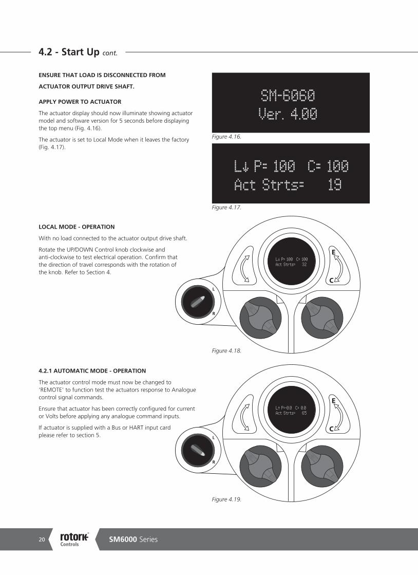
ENSURE THAT LOAD IS DISCONNECTED FROM
ACTUATOR OUTPUT DRIVE SHAFT.
APPLY POWER TO ACTUATOR
The actuator display should now illuminate showing actuator model and software version for 5 seconds before displaying the top menu (Fig. 4.16).
The actuator is set to Local Mode when it leaves the factory (Fig. 4.17).
LOCAL MODE - OPERATION
With no load connected to the actuator output drive shaft.
Rotate the UP/DOWN Control knob clockwise and anti-clockwise to test electrical operation. Confirm that the direction of travel corresponds with the rotation of the knob. Refer to Section 4.
4.2.1 AUTOMATIC MODE - OPERATION
The actuator control mode must now be changed to ‘REMOTE’ to function test the actuators response to Analogue control signal commands.
Ensure that actuator has been correctly configured for current or Volts before applying any analogue command inputs.
If actuator is supplied with a Bus or HART input card please refer to section 5.
SM-6060Ver. 4.00
L P= 100 C= 100Act Strts= 19
L P= 100 C= 100Act Strts= 32
L P=-0.0 C= 0.0Act Strts= 65
Figure 4.16.
Figure 4.17.
Figure 4.18.
Figure 4.19.

Keeping the World Flowing 21
4.2 - Start Up cont.
ENTER KNOB - SELECT ‘CANCEL’
SETUP MODE
Display now shows Setup Menu (Fig. 4.20).
S / pick paramPress
C
Figure 4.20.
SM6000 Series22
4.2 - Start Up cont.
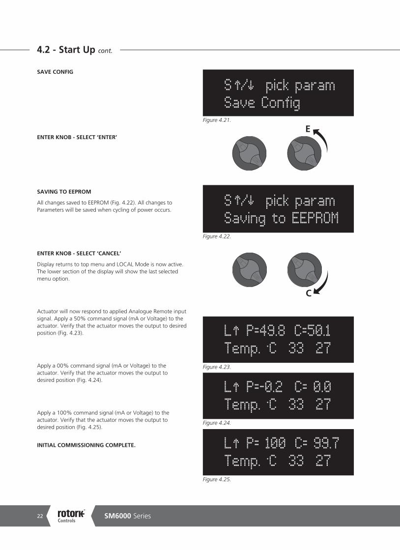
SAVE CONFIG
ENTER KNOB - SELECT ‘ENTER’
SAVING TO EEPROM
All changes saved to EEPROM (Fig. 4.22). All changes to Parameters will be saved when cycling of power occurs.
ENTER KNOB - SELECT ‘CANCEL’
Display returns to top menu and LOCAL Mode is now active. The lower section of the display will show the last selected menu option.
Actuator will now respond to applied Analogue Remote input signal. Apply a 50% command signal (mA or Voltage) to the actuator. Verify that the actuator moves the output to desired position (Fig. 4.23).
Apply a 00% command signal (mA or Voltage) to the actuator. Verify that the actuator moves the output to desired position (Fig. 4.24).
Apply a 100% command signal (mA or Voltage) to the actuator. Verify that the actuator moves the output to desired position (Fig. 4.25).
INITIAL COMMISSIONING COMPLETE.
S / pick paramSave Config
S / pick paramSaving to EEPROM
L P=49.8 C=50.1Temp. .C 33 27
L P=-0.2 C= 0.0Temp. .C 33 27
L P= 100 C= 99.7Temp. .C 33 27
C
EFigure 4.21.
Figure 4.22.
Figure 4.23.
Figure 4.25.
Figure 4.24.

Keeping the World Flowing 23
4.3 - Range of Operation - Setup
4.3.1 RANGE OF OPERATION
The following procedure will calibrate the ZERO and SPAN limits of travel and adjustment of the Position Limit Switches if necessary.
With Linkage disconnected apply power to the unit.
The actuator should be in local mode to start this operation as noted in Figure 4.18. Refer to section 4 for instructions. The unit may have been moved out of its normal limits of electrical travel for shipping purposes. In this case Figure 4.27 shows the actuator at 149% of travel. The actuator will respond to decreasing requests only, until it reaches the 100% position of travel, after which it may be driven in either direction between limits (Fig. 4.28).
During operation it is possible that one end of travel switch is tripped and adjustment is required to facilitate movement to the desired SPAN or ZERO position. In this case it will be necessary to adjust one or both of the travel limit switches.
Fig 4.28 shows that the increasing limit switch cam#1 has been activated.
WARNING
Isolate power supply before inserting tools in to the electrical housing.
Move actuator output shaft in the increasing direction and observe rotation of cam switch assembly to verify CW or ACW operation. Using a 1/8” hex wrench loosen the appropriate locking screw (screws are numbered on the cam end plate) (Fig 4.29).
Move the switch cam in the decreasing direction to allow the actuator to run its full required position of travel. Once adjusted tighten the locking screw.
Repeat the procedure for the Decreasing travel limit if necessary.
Figure 4.26.
L P= 149 C= 149 Temp. .C 32 27
Figure 4.27.
L P= 100 C= 100 Flt: Inc Limit
Figure 4.28.
Figure 4.29.
Figure 4.30.Figure 4.31.

SM6000 Series24
4.3 - Range of Operation - Setup cont.
OPERATING SPEED
The actuator output speed is factory preset to 100%. During the initial calibration of this unit it is recommended that the speed is reduced to 10% to achieve greater accuracy when setting the ZERO and SPAN position limits.
To change the actuator speed.
Select ‘LOCAL’ operation
L P= 149 C= 149 Temp. .C 32 27
S / pick param Speed = 100
/ to SpeedENT = acpt 100
C
E
D
Figure 4.32.
Figure 4.33.
Figure 4.34.
UP/DOWN KNOB - SELECT ‘SPEED SETUP MENU’
Use the UP/DOWN knob to scroll through menus.
Until ‘Speed = XXX’ is displayed (Fig. 4.33).
ENTER KNOB - SELECT ‘ENTER’
The motor speed can now be adjusted by using the UP/DOWN knob.
L
R

Keeping the World Flowing 25
4.3 - Range of Operation - Setup cont.
UP/DOWN KNOB - HOLD TO REDUCE SPEED
Hold the UP/DOWN KNOB until the actuator speed indicates 10% (Fig. 4.35).
ENTER KNOB - ENTER TO SAVE VALUE
Select ‘ENTER’ to set the actuator speed to 10% (Fig. 4.36).
UP/DOWN KNOB - SELECT ‘SAVE CONFIG’
Actuator configuration should be saved to EEPROM before exiting the menu (Fig. 4.37).
/ to SpeedENT = acpt 10
S / pick param Save Config
D
Figure 4.37.
Figure 4.35.
S / pick param Speed = 10
E
Figure 4.36.
D
SM6000 Series26
4.3 - Range of Operation - Setup cont.
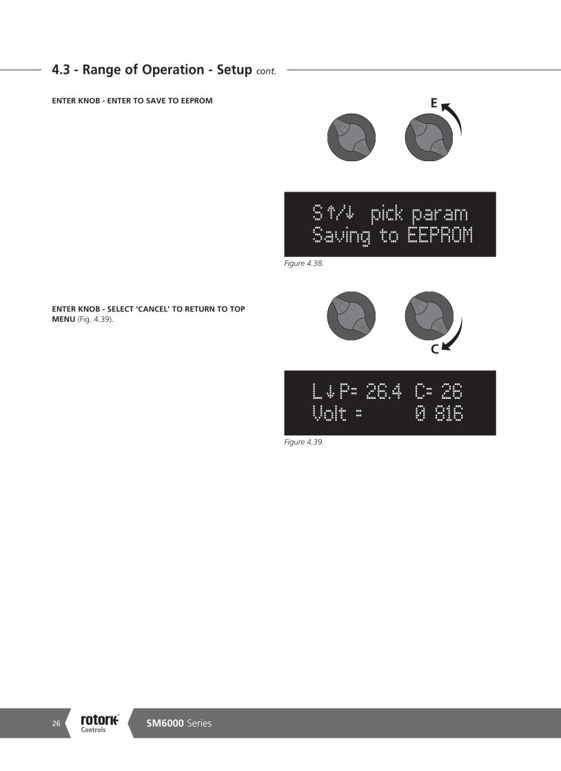
ENTER KNOB - ENTER TO SAVE TO EEPROM
ENTER KNOB - SELECT ‘CANCEL’ TO RETURN TO TOP MENU (Fig. 4.39).
S / pick param Saving to EEPROM
E
Figure 4.38.
C
L P= 26.4 C= 26 Volt = 0 816
Figure 4.39.
Keeping the World Flowing 27
4.3 - Range of Operation - Setup cont.
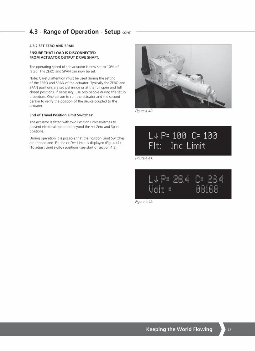
4.3.2 SET ZERO AND SPAN
ENSURE THAT LOAD IS DISCONNECTED FROM ACTUATOR OUTPUT DRIVE SHAFT.
The operating speed of the actuator is now set to 10% of rated. The ZERO and SPAN can now be set.
Note: Careful attention must be used during the setting of the ZERO and SPAN of the actuator. Typically the ZERO and SPAN positions are set just inside or at the full open and full closed positions. If necessary, use two people during the setup procedure. One person to run the actuator and the second person to verify the position of the device coupled to the actuator.
End of Travel Position Limit Switches:
The actuator is fitted with two Position Limit switches to prevent electrical operation beyond the set Zero and Span positions.
During operation it is possible that the Position Limit Switches are tripped and ‘Flt. Inc or Dec Limit, is displayed (Fig. 4.41). (To adjust Limit switch positions (see start of section 4.3).
L P= 26.4 C= 26.4 Volt = 08168
L P= 100 C= 100 Flt: Inc Limit
Figure 4.40.
Figure 4.41.
Figure 4.42.

SM6000 Series28
4.3 - Range of Operation - Setup cont.
SET ZERO POSITION
The ZERO position is the position that the actuator will travel to when given its minimum command. Typically this is the closed position of the device. To set the ZERO position, follow the procedure below:
ENTER KNOB - SELECT ‘CANCEL’ TO ENTER SETUP MODE
UP/DOWN KNOB - SELECT ‘ZERO’ MENU
The actuator position in this menu is shown as a 5 digit encoder count (Fig. 4.44).
S / pick paramZERO = 06616
D
Figure 4.44.
S / pick paramPress
C
Figure 4.43.
Keeping the World Flowing 29
4.3 - Range of Operation - Setup cont.
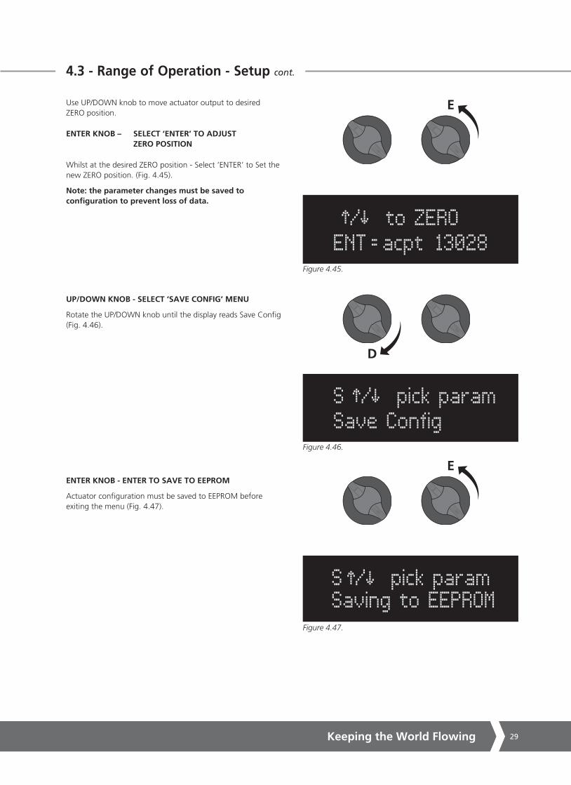
Use UP/DOWN knob to move actuator output to desired ZERO position.
ENTER KNOB – SELECT ‘ENTER’ TO ADJUST ZERO POSITION
Whilst at the desired ZERO position - Select ‘ENTER’ to Set the new ZERO position. (Fig. 4.45).
Note: the parameter changes must be saved to configuration to prevent loss of data.
UP/DOWN KNOB - SELECT ‘SAVE CONFIG’ MENU
Rotate the UP/DOWN knob until the display reads Save Config (Fig. 4.46).
ENTER KNOB - ENTER TO SAVE TO EEPROM
Actuator configuration must be saved to EEPROM before exiting the menu (Fig. 4.47).
/ to ZEROENT = acpt 13028
E
Figure 4.45.
S / pick paramSave Config
D
Figure 4.46.
S / pick param Saving to EEPROM
E
Figure 4.47.
SM6000 Series30
4.3 - Range of Operation - Setup cont.
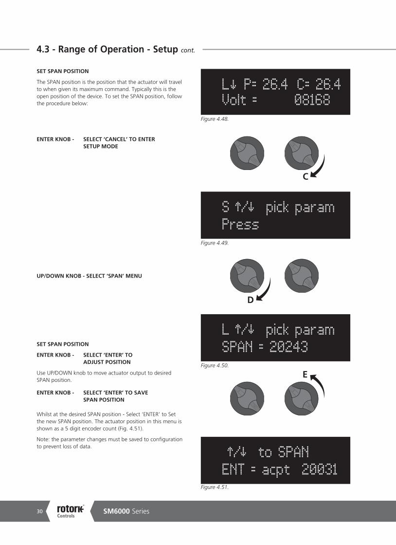
SET SPAN POSITION
The SPAN position is the position that the actuator will travel to when given its maximum command. Typically this is the open position of the device. To set the SPAN position, follow the procedure below:
ENTER KNOB - SELECT ‘CANCEL’ TO ENTER SETUP MODE
UP/DOWN KNOB - SELECT ‘SPAN’ MENU
SET SPAN POSITION
ENTER KNOB - SELECT ‘ENTER’ TO ADJUST POSITION
Use UP/DOWN knob to move actuator output to desired SPAN position.
ENTER KNOB - SELECT ‘ENTER’ TO SAVE SPAN POSITION
Whilst at the desired SPAN position - Select ‘ENTER’ to Set the new SPAN position. The actuator position in this menu is shown as a 5 digit encoder count (Fig. 4.51).
Note: the parameter changes must be saved to configuration to prevent loss of data.
S / pick paramPress
L / pick paramSPAN = 20243
/ to SPANENT = acpt 20031
L P= 26.4 C= 26.4 Volt = 08168
C
E
D
Figure 4.48.
Figure 4.49.
Figure 4.50.
Figure 4.51.

Keeping the World Flowing 31
4.3 - Range of Operation - Setup cont.
UP/DOWN KNOB - SELECT ‘SAVE CONFIG’ MENU
Rotate the UP/DOWN knob until the display reads Save Config. (Fig. 4.52).
ENTER KNOB - ENTER TO SAVE TO EEPROM
Actuator configuration must be saved to EEPROM before exiting the menu (Fig. 4.53).
ENTER KNOB - SELECT ‘CANCEL’
Select ‘CANCEL’ to exit setup mode.
The SPAN position has now been set (Fig. 4.54).
If limits have not been set adjustment of the position limit switches is required. See start of section 4.3.
L P= 0.0 C= 0.0 Volt = 1 8168
S / pick paramSave Config
C
D
Figure 4.52.
S / pick param Saving to EEPROM
E
Figure 4.53.
Figure 4.54.

SM6000 Series32
4.3 - Range of Operation - Setup cont.
4.3.3 SETTING LIMIT SWITCHES
SET INCREASING POSITION LIMIT SWITCH CAM#1
It is now possible to set the CW & ACW position limit switches.
With actuator set to LOCAL mode (see section 4.2) move output shaft to the ACW end of travel position. As viewed from the lever output shaft end.
This could be the ZERO or SPAN position depending on configuration.
The switch acts as an emergency backup to de-energize the motor drive and is generally set to trip if the actuator is operated outside the SPAN or ZERO travel positions.
Locate locking set screw #1 on the switch cam end plate assembly.
With a 1/8” Hex key loosen (DO NOT REMOVE) locking grub screw (Fig. 4.55).
Rotate the cam CW until the switch operates (Fig. 4.57) then back off so that the cam just releases the switch.
Tighten the set screw (Fig. 4.58).
The switch is now set to operate just after the anti-clockwise (ZERO or SPAN ) position is reached.
SET DECREASING POSITION LIMIT SWITCH CAM#2
With actuator set to LOCAL mode (see section 4.2) move output shaft to the CW end of travel position. As viewed from the lever output shaft end.
This could be the ZERO or SPAN position depending on configuration.
Locate locking set screw #2 on the switch cam end plate assembly (Fig. 4.56).
With a 1/8” Hex key loosen (DO NOT REMOVE) locking grub screw.
Rotate the cam ACW until the switch operates then back off so that the cam just releases the switch (Fig. 4.57).
Tighten the set screw (Fig. 4.58).
The switch is now set to operate just after the ACW (ZERO or SPAN) position is reached.
Note: CW = Clockwise ACW = Anti-Clockwise (Counter- Clockwise)
Figure 4.55.
Figure 4.56.
Figure 4.57.
Figure 4.58.

Keeping the World Flowing 33
4.3 - Range of Operation - Setup cont.
SET ADDITIONAL LIMIT SWITCHES (If fitted)
Repeat the procedure for switches CAM #3 to #6 as required.
REFIT TOP AND SIDE COVERS
Check condition of o-ring seals (replace if necessary) and refit cover assemblies.
REFIT LOCAL CONTROL COVER ASSEMBLY
Remove the control cover assembly from its temporary position and refit to front of control housing. Take care not to damage looms between the cover assembly and the main PCB. Disconnect wiring looms if necessary. Be sure to check condition of the o-ring seals (replace if necessary) and refit with cover.
Figure 4.59.

SM6000 Series34
4.3.4 OPERATING SPEED
The actuator output speed can now be changed to suit the process requirement.
To change the actuator speed.
ENTER KNOB - SELECT ‘CANCEL’
UP/DOWN KNOB - SELECT ‘MENU’
Use the UP/DOWN knob to scroll through menus until ‘Speed = XXX’ is displayed (Fig. 4.62).
UP/DOWN KNOB - SELECT SPEED
The motor speed can now be adjusted by using the UP/DOWN knob until the display shows the desired speed (10 - 100%) (Fig. 4.62).
D
U
L P= 149 C= 149 Temp. .C 32 27
Figure 4.60.
S / pick param Speed = 100
D
Figure 4.62.
4.3 - Range of Operation - Setup cont.
S / pick param Ctrl Type = Man
C
Figure 4.61.
Keeping the World Flowing 35
4.3 - Range of Operation - Setup cont.
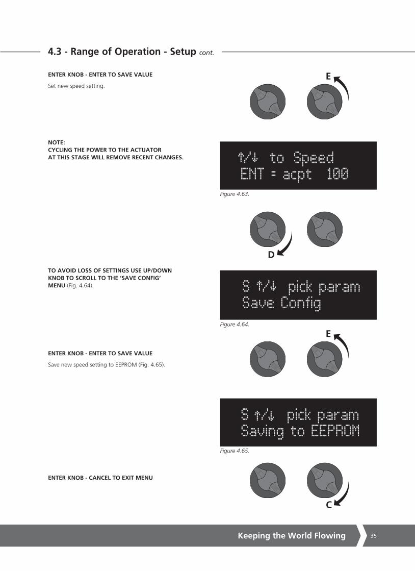
ENTER KNOB - ENTER TO SAVE VALUE
Set new speed setting.
NOTE: CYCLING THE POWER TO THE ACTUATOR AT THIS STAGE WILL REMOVE RECENT CHANGES.
TO AVOID LOSS OF SETTINGS USE UP/DOWN KNOB TO SCROLL TO THE ‘SAVE CONFIG‘ MENU (Fig. 4.64).
ENTER KNOB - ENTER TO SAVE VALUE
Save new speed setting to EEPROM (Fig. 4.65).
ENTER KNOB - CANCEL TO EXIT MENU
/ to Speed ENT = acpt 100
S / pick paramSave Config
S / pick param Saving to EEPROM
C
E
E
D
Figure 4.63.
Figure 4.64.
Figure 4.65.

SM6000 Series36
5 - Setup and Calibration
SM-6000 S2 MENU STRUCTURE
SECT 5.1 SETUP & CALIBRATION
SECT 5.2 COMMUNICATIONS
There are two levels of Setup and Calibration.
Level 1: Customer Settings for initial setup and fine tuning of the actuator operation.
Level 2: Diagnostic and Advanced Settings (Section 5.3). User may wish to consult Rotork Controls before making changes to level 2 parameters.
LEVEL 1 MENU STRUCTURE
SPAN
ZERO
MAX CAL
MIN CAL
SPEED
COMMS OPT
CMD TYPE
LOS ACT
LOS POS
CUR P GAIN
CUR I GAIN
MIN POS
MAX POS
MAX TORQUE
SAVE CONFIG
PROFIBUS
CTRL MECH
PROFI ADDR
FB POS LIM
COM LOS ACT
COM LOS P
COM LOS TO
HART
CTRL MECH
HART ADDR
COM LOS ACT
COM LOS P
COM LOS TO
CTRL MECH
FB POS LIM
COM LOS ACT
COM LOS P
COM LOS TO
FFBUS
SETUP MODE
Figure 5.1. Level 1 Menu Structure
Keeping the World Flowing 37
S / pick param Ctrl Type = REMOTE
LEVEL 1
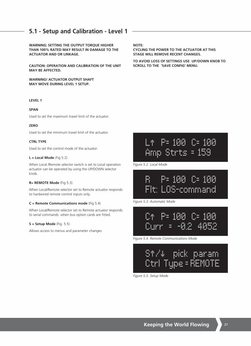
SPAN
Used to set the maximum travel limit of the actuator.
ZERO
Used to set the minimum travel limit of the actuator.
CTRL TYPE
Used to set the control mode of the actuator.
L = Local Mode (Fig 5.2)
When Local /Remote selector switch is set to Local operation actuator can be operated by using the UP/DOWN selector knob.
R= REMOTE Mode (Fig 5.3)
When Local/Remote selector set to Remote actuator responds to hardwired remote control inputs only.
C = Remote Communications mode (Fig 5.4)
When Local/Remote selector set to Remote actuator responds to serial commands when bus option cards are fitted.
S = Setup Mode (Fig. 5.5)
Allows access to menus and parameter changes.
WARNING: SETTING THE OUTPUT TORQUE HIGHER THAN 100% RATED MAY RESULT IN DAMAGE TO THE ACTUATOR AND OR LINKAGE.
CAUTION: OPERATION AND CALIBRATION OF THE UNIT MAY BE AFFECTED.
WARNING! ACTUATOR OUTPUT SHAFT MAY MOVE DURING LEVEL 1 SETUP.
NOTE: CYCLING THE POWER TO THE ACTUATOR AT THIS STAGE WILL REMOVE RECENT CHANGES.
TO AVOID LOSS OF SETTINGS USE UP/DOWN KNOB TO SCROLL TO THE ‘SAVE CONFIG‘ MENU.
R P= 100 C= 100 Flt: LOS-command
C P= 100 C= 100 Curr = -0.2 4052
L P= 100 C= 100 Amp Strts = 159
Figure 5.2. Local Mode
Figure 5.3. Automatic Mode
Figure 5.4. Remote Communications Mode
Figure 5.5. Setup Mode
5.1 - Setup and Calibration - Level 1

SM6000 Series38
5.1 - Setup and Calibration - Level 1 cont.
5.1.1 MAX CMD CAL
Used to calibrate the analogue command signal to the desired MAX position. This maximises resolution and optimises accuracy.
The analogue control signal should be applied to terminals as follows.
Voltage TB2-1 (+ve) TB2-2 (-ve)
Current TB2-4 (+ve) TB2-3 (-ve)
Refer to the identification label located on the outside of the actuator for wiring diagram details.
1 - Enter setup mode (see section 4.2).
2 - Use the ENTER knob to scroll through menus until ’MAX = XXXX ’ is displayed on line 2.
3 - Select ‘ENTER’.
SET CMND TO MAX will appear on line 1 of the display.
4 - Apply the maximum input command e.g. 20 mA.
5 - Select ‘ENTER’ to accept the new Max Cal value,
Select ‘CANCEL’ to exit the Max Cal setup mode.
5.1.2 MIN CMD CAL
Used to calibrate the analogue command signal to the desired MIN position. This maximises resolution and optimises accuracy.
1 - Enter setup mode (see section 4.2).
2 - Use the ‘Enter‘ knob to scroll through menus until ’MIN = XXXX’ is displayed on line 2.
3 - Select ‘ENTER’.
SET CMND TO MIN will appear on line 1 of the display.
4 - Apply the minimum input command e.g. 4 mA.
5 - Select ‘ENTER’ to accept the new Min Cal value,
Select ‘CANCEL’ to exit the Min Cal setup mode.
C
E
C
E
Figure 5.6. MAX CMD CAL
Figure 5.7. MIN CMD CAL
S / pick param Max Cal = 7684
S / pick param Min Cal = 1541

Keeping the World Flowing 39
5.1 - Setup and Calibration - Level 1 cont.
5.1.3 SPEED
The actuator output speed is adjustable from 1 - 100% of its rated value.
1 - Enter setup mode (see section 4.2).
2 - Use the UP/DOWN knob to scroll through menus until ‘Speed = XXX‘ appears on line 2 of the display.
3 - Select ‘ENTER’.
4 - Hold the UP/DOWN knob until desired value is displayed.
5 - Select ‘ENTER’ to accept new Speed value, or select ‘CANCEL’ to abort without changing the speed value.
5.1.4 CMD TYPE
Used to select between Current (4-20 mA) or Voltage (0-5 VDC or 0-10 VDC).
1 - Enter setup mode (see section 4.2).
2 - Use UP/DOWN knob until ‘COMMAND =XXXX’ is displayed.
3 - Select ‘ENTER’.
4 - Use UP/DOWN knob to select Current or Voltage.
5 - Select ‘ENTER’ to accept the change.
CANCEL to exit the menu.
5.1.5 LOS ACT
Used to determine the actuator action on loss of analogue control signal when the actuator is set to Automatic Mode of operation.
LOCK - Stayput or Lock in place. POS - Go to Preset Position.
1 - Enter setup mode (see section 4.2).
2 - Use UP/DOWN knob until LOS ACT is displayed.
3 - Select ‘ENTER’.
4 - Use UP/DOWN knob to select desired value.
5 - Select ‘ENTER’ to accept the change.
CANCEL to exit the menu.
D
U
D
U
D
U
Figure 5.8. SPEED
Figure 5.10. LOS ACT
Figure 5.9. CMD TYPE
S / pick param Speed = 100
S / pick param Cmd Type = Volt
S / pick param LOS Act = Lock

SM6000 Series40
5.1 - Setup and Calibration - Level 1 cont.
5.1.6 LOS POS
Used to determine the position that the actuator will move to on loss of analogue control signal.
1 - Enter setup mode (see section 4.2).
2 - Use UP/DOWN knob until LOS POS is displayed.
3 - Select ‘ENTER’.
4 - Use UP/DOWN knob to select desired value.
5 - Select ‘ENTER’ to accept the change.
CANCEL to exit the menu.
5.1.7 CUR P GAIN
Used to adjust the proportional gain of the actuator. Modifies the response of the actual position against desired position. Range 1-99.
1 - Enter setup mode (see section 4.2).
2 - Use UP/DOWN knob until CUR P GAIN is displayed.
3 - Select ‘ENTER’.
4 - Use UP/DOWN knob to select desired value.
5 - Select ‘ENTER’ to accept the change.
CANCEL to exit the menu.
5.1.8 CUR I GAIN
Used to adjust the integral gain of the actuator where system response varies over time. Range 0-99.
1 - Enter setup mode (see section 4.2).
2 - Use UP/DOWN knob until CUR I GAIN is displayed.
3 - Select ‘ENTER’.
4 - Use UP/DOWN knob to select desired value.
5 - Select ‘ENTER’ to accept the change.
CANCEL to exit the menu.
D
U
D
U
D
U
Figure 5.11. LOS POS
Figure 5.13. CUR I GAIN
Figure 5.12. CUR P GAIN
S / pick param LOS Pos = 18844
S / pick param Cur P Gain = 40
S / pick param Cur I Gain = 20

Keeping the World Flowing 41
5.1.9 MIN POS
Used to set the position regarded as ZERO when limited range positioning is required. Only applicable when the FB Pos Limit is active. For example if MIN POS is set to 10% this is reported as the ZERO (0%) position.
1 - Enter setup mode (see section 4.2).
2 - Use UP/DOWN knob until MIN POS is displayed.
3 - Select ‘ENTER’.
4 - Use UP/DOWN knob to move the actuator to the desired position.
5 - Select ‘ENTER’ to accept the change.
CANCEL to exit the menu.
5.1.10 MAX POS
Used to set the position regarded as SPAN when limited range positioning is required. Only applicable when the FB Pos Limit is active. For example if MAX POS is set to 90% this is reported as the SPAN (100%) position.
1 - Enter setup mode (see section 4.2).
2 - Use UP/DOWN knob until MIN POS is displayed.
3 - Select ‘ENTER’.
4 - Use UP/DOWN knob to move the actuator to the desired position.
5 - Select ‘ENTER’ to accept the change.
CANCEL to exit the menu.
D
U
D
U
Figure 5.14. MIN POS
Figure 5.15. MAX POS
S / pick param Min Pos = 0
5.1 - Setup and Calibration - Level 1 cont.
S / pick param Min Pos = 100

SM6000 Series42
5.1 - Setup and Calibration - Level 1 cont.
5.1.11 MAX TORQUE %
Used to limit the output torque produced by the actuator.Exceeding the value will result in an over torque alarm being displayed.
1 - Enter setup mode (see section 4.2).
2 - Use UP/DOWN knob until Max TORQUE is displayed. Max value = 200% of rated,
3 - Select ‘ENTER’
4 - Use UP/DOWN knob to select desired value.
5 - Select ‘ENTER’ to accept the change.
CANCEL to exit the menu.
5.1.12 SAVE CONFIG
Used to save setup parameters to EEPROM. Any parameter changes MUST be saved prior to power off. On power up the on board processor will use the last values stored in the EEPROM.
1 - Enter setup mode (see section 4.2).
2 - Use UP/DOWN knob until SAVE CONFIG is displayed.
3 - Select ‘ENTER’ to save changes to EEPROM.
CANCEL to exit the menu.
SETUP COMPLETE
Set the REMOTE/Local parameter to REMOTE.
D
U
D
U
Figure 5.16. MAX TORQUE %
Figure 5.17. SAVE CONFIG
S / pick param Max Torq % = 100
S / pick param Save Config

Keeping the World Flowing 43
5.2 - Communications
COMMS OPT
Used to select specific menus when a BUS communications option card is fitted.
1 - Enter setup mode (see section 4.2).
2 - Use UP/DOWN knob until COMS OPT is displayed.
3 - Select ‘ENTER’.
4 - Use UP/DOWN knob to select the actuator control protocol.
Choices are: NONE No Bus Protocol option fitted. HART PROFIBUS FFBUS (Foundation Fieldbus)
5 - Select ‘ENTER’ to accept the change.
The selected communication protocol options will now be available.
Note that the unit must be fitted with the appropriate Bus system card to support the menus.
5.2.1 HART CONTROL OPTIONS
CTRL MECH
The actuator can be controlled via commands received over the Hart protocol communications channel or as a direct analogue (4-20 mA) input signal request.
1 - Enter setup mode (see section 4.2).
2 - Use UP/DOWN knob until CTRL MECH is displayed.
3 - Select ‘ENTER’.
4 - Use UP/DOWN knob to select the actuator control type.
Menu choices are: COMMS = HART protocol control ANALOG = 4-20 mA Analogue Control only.
5 - Select ENTER to accept the change.
CANCEL to exit the menu.
HART ADDR
Used to set the address assigned to the device on the HART network. Range 1 to 64.
1 - Enter setup mode (see section 4.2).
2 - Use UP/DOWN knob until HART ADDR is displayed.
3 - Select ‘ENTER’.
4 - Use UP/DOWN knob until desired address is displayed
5 - Select ‘ENTER’.
CANCEL to exit the menu.
Figure 5.18
D
U
Figure 5.19. COMMS OPT
S / pick param COMMS Opt = HART
D
U
Figure 5.20. CTRL MECH
S / pick param Ctrl Mech = COMMS
D
U
Figure 5.21. HART ADDR
S / pick param HART Addr = 0
HART
CTRL MECH
HART ADDR
COM LOS ACT
COM LOS P
COM LOS TO
SM6000 Series44
5.2 - Communications cont.
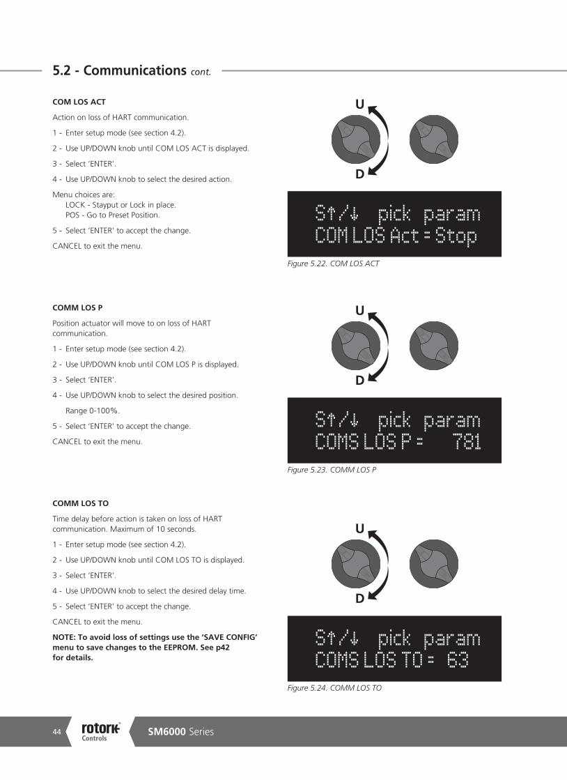
COM LOS ACT
Action on loss of HART communication.
1 - Enter setup mode (see section 4.2).
2 - Use UP/DOWN knob until COM LOS ACT is displayed.
3 - Select ‘ENTER’.
4 - Use UP/DOWN knob to select the desired action.
Menu choices are: LOCK - Stayput or Lock in place. POS - Go to Preset Position.
5 - Select ‘ENTER’ to accept the change.
CANCEL to exit the menu.
COMM LOS P
Position actuator will move to on loss of HART communication.
1 - Enter setup mode (see section 4.2).
2 - Use UP/DOWN knob until COM LOS P is displayed.
3 - Select ‘ENTER’.
4 - Use UP/DOWN knob to select the desired position.
Range 0-100%.
5 - Select ‘ENTER’ to accept the change.
CANCEL to exit the menu.
COMM LOS TO
Time delay before action is taken on loss of HART communication. Maximum of 10 seconds.
1 - Enter setup mode (see section 4.2).
2 - Use UP/DOWN knob until COM LOS TO is displayed.
3 - Select ‘ENTER’.
4 - Use UP/DOWN knob to select the desired delay time.
5 - Select ‘ENTER’ to accept the change.
CANCEL to exit the menu.
NOTE: To avoid loss of settings use the ‘SAVE CONFIG’ menu to save changes to the EEPROM. See p42 for details.
Figure 5.22. COM LOS ACT
Figure 5.24. COMM LOS TO
Figure 5.23. COMM LOS P
D
U
D
U
D
U
S / pick param COM LOS Act = Stop
S / pick param COMS LOS P = 781
S / pick param COMS LOS TO = 63

Keeping the World Flowing 45
5.2 - Communications cont.
5.2.2 PROFIBUS CONTROL OPTIONS
CTRL MECH
The actuator can be controlled via commands received over the Profibus protocol communications channel or as a direct analogue (4-20 mA) input signal request.
1 - Enter setup mode (see section 4.2).
2 - Use UP/DOWN knob until CTRL MECH is displayed.
3 - Select ‘ENTER’.
4 - Use UP/DOWN knob to select the actuator control type.
Menu choices are: COMMS = Profibus protocol control ANALOG = 4-20 mA Analogue Control only.
5 - Select ‘ENTER’ to accept the change.
CANCEL to exit the menu.
PROFI ADDR
Used to set the address assigned to the device on the Profibus network. Range 1 to 127.
1 - Enter setup mode (see section 4.2).
2 - Use UP/DOWN knob until PROFI ADDR is displayed.
3 - Select ‘ENTER’.
4 - Use UP/DOWN knob until desired address is displayed.
5 - Select ‘ENTER’.
CANCEL to exit the menu.
FB POS LIMIT
Feedback position limiting. When enabled the actuator will return a zero value when the actuator is below the MIN POS limit and 100% above the MAX POS Limit.
1 - Enter setup mode (see section 4.2).
2 - Use UP/DOWN knob until FB POS LIMIT is displayed.
3 - Select ‘ENTER’.
4 - Use UP/DOWN to select Enable or Disable function.
5 - Select ‘ENTER’.
CANCEL to exit the menu.
Figure 5.25
D
U
Figure 5.26. CTRL MECH
S / pick param Ctrl Mech = COMMS
D
U
Figure 5.27. PROFI ADDR
S / pick param PROFI addr = 126
D
U
Figure 5.28. FB POS LIMIT
S / pick param FB Pos Limit = No
PROFIBUS
CTRL MECH
PROFI ADDR
FB POS LIM
COM LOS ACT
COM LOS P
COM LOS TO

SM6000 Series46
5.2 - Communications cont.
COM LOS ACT
Action on loss of Profibus communication.
1 - Enter setup mode (see section 4.2).
2 - Use UP/DOWN knob until COM LOS ACT is displayed.
3 - Select ‘ENTER’.
4 - Use UP/DOWN knob to select the desired action.
Menu choices are: LOCK - Stayput or Lock in place. POS - Go to Preset Position.
5 - Select ‘ENTER’ to accept the change.
CANCEL to exit the menu.
COMM LOS P
Position actuator will move to on loss of Profibus communication.
1 - Enter setup mode (see section 4.2).
2 - Use UP/DOWN knob until COM LOS P is displayed.
3 - Select ‘ENTER’.
4 - Use UP/DOWN knob to select the desired position.
Range 0-100%.
5 - Select ‘ENTER’ to accept the change.
CANCEL to exit the menu.
COMM LOS TO
Time delay before action is taken on loss of Profibus communication. Maximum of 10 seconds.
1 - Enter setup mode (see section 4.2).
2 - Use UP/DOWN knob until COM LOS TO is displayed.
3 - Select ‘ENTER’.
4 - Use UP/DOWN knob to select the desired delay time.
5 - Select ‘ENTER’ to accept the change.
CANCEL to exit the menu.
NOTE: To avoid loss of settings use the ‘SAVE CONFIG’ menu to save changes to the EEPROM. See p42 for details.
Figure 5.29. COM LOS ACT
Figure 5.31. COMM LOS TO
Figure 5.30. COMM LOS P
D
U
D
U
D
U
S / pick param COM LOS Act = Stop
S / pick param COMS LOS P = 781
S / pick param COMS LOS TO = 255
Keeping the World Flowing 47
5.2 - Communications cont.
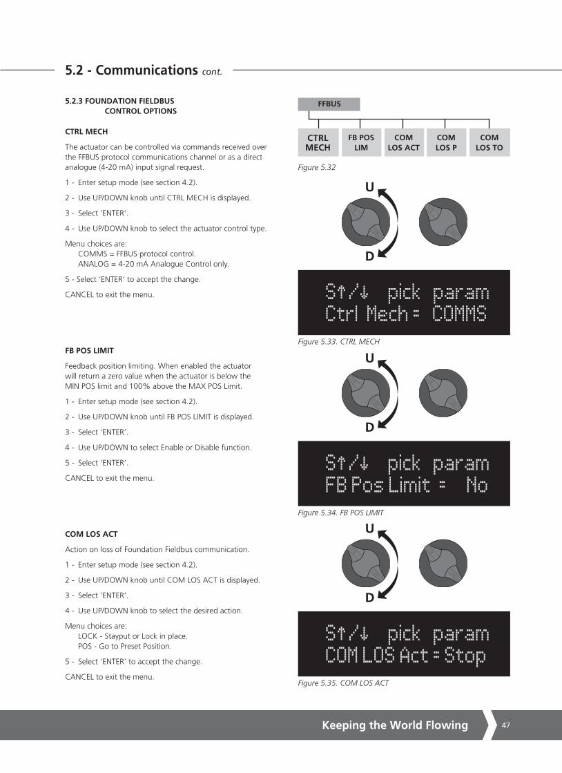
5.2.3 FOUNDATION FIELDBUS CONTROL OPTIONS
CTRL MECH
The actuator can be controlled via commands received over the FFBUS protocol communications channel or as a direct analogue (4-20 mA) input signal request.
1 - Enter setup mode (see section 4.2).
2 - Use UP/DOWN knob until CTRL MECH is displayed.
3 - Select ‘ENTER’.
4 - Use UP/DOWN knob to select the actuator control type.
Menu choices are: COMMS = FFBUS protocol control. ANALOG = 4-20 mA Analogue Control only.
5 - Select ‘ENTER’ to accept the change.
CANCEL to exit the menu.
FB POS LIMIT
Feedback position limiting. When enabled the actuator will return a zero value when the actuator is below the MIN POS limit and 100% above the MAX POS Limit.
1 - Enter setup mode (see section 4.2).
2 - Use UP/DOWN knob until FB POS LIMIT is displayed.
3 - Select ‘ENTER’.
4 - Use UP/DOWN to select Enable or Disable function.
5 - Select ‘ENTER’.
CANCEL to exit the menu.
COM LOS ACT
Action on loss of Foundation Fieldbus communication.
1 - Enter setup mode (see section 4.2).
2 - Use UP/DOWN knob until COM LOS ACT is displayed.
3 - Select ‘ENTER’.
4 - Use UP/DOWN knob to select the desired action.
Menu choices are: LOCK - Stayput or Lock in place. POS - Go to Preset Position.
5 - Select ‘ENTER’ to accept the change.
CANCEL to exit the menu.
Figure 5.32
D
U
Figure 5.33. CTRL MECH
S / pick param Ctrl Mech = COMMS
D
U
Figure 5.34. FB POS LIMIT
S / pick param FB Pos Limit = No
FFBUS
CTRL MECH
FB POS LIM
COM LOS ACT
COM LOS P
COM LOS TO
D
U
Figure 5.35. COM LOS ACT
S / pick param COM LOS Act = Stop
SM6000 Series48
5.2 - Communications cont.
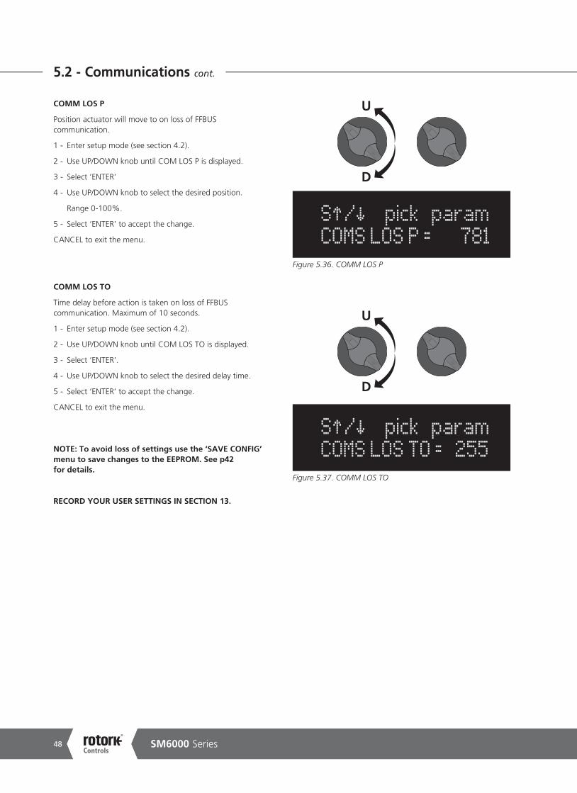
Figure 5.37. COMM LOS TO
D
U
S / pick param COMS LOS TO = 255
COMM LOS P
Position actuator will move to on loss of FFBUS communication.
1 - Enter setup mode (see section 4.2).
2 - Use UP/DOWN knob until COM LOS P is displayed.
3 - Select ’ENTER’
4 - Use UP/DOWN knob to select the desired position.
Range 0-100%.
5 - Select ‘ENTER’ to accept the change.
CANCEL to exit the menu.
COMM LOS TO
Time delay before action is taken on loss of FFBUS communication. Maximum of 10 seconds.
1 - Enter setup mode (see section 4.2).
2 - Use UP/DOWN knob until COM LOS TO is displayed.
3 - Select ‘ENTER’.
4 - Use UP/DOWN knob to select the desired delay time.
5 - Select ‘ENTER’ to accept the change.
CANCEL to exit the menu.
NOTE: To avoid loss of settings use the ‘SAVE CONFIG’ menu to save changes to the EEPROM. See p42 for details.
RECORD YOUR USER SETTINGS IN SECTION 13.
D
U
Figure 5.36. COMM LOS P
S / pick param COMS LOS P = 781

Keeping the World Flowing 49
5.3 - Setup and Calibration - Level 2
SETUP MODELEVEL 2
MOTOR
MAX TORQUE
INPUT VOLT
MOTOR RATE
PASS ENBLD
LOOP
LOAD FACT DEFS
SAVE CONFIG
Figure 5.38. Level 2 Menu Structure
SM-6000 S2 MENU STRUCTURE
Level 2: Diagnostic and Advanced Settings. User may wish to consult Rotork Controls before making changes to level 2 parameters.
SM6000 Series50
5.3 - Setup and Calibration - Level 2 cont.
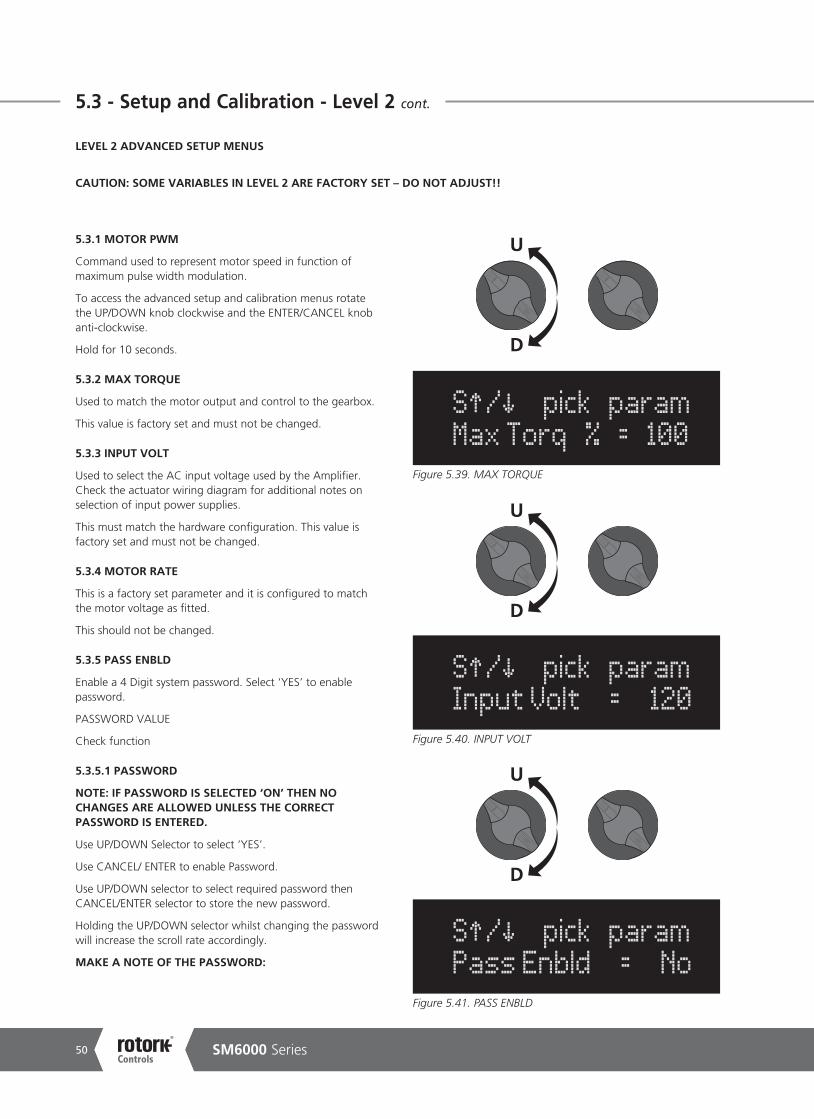
5.3.1 MOTOR PWM
Command used to represent motor speed in function of maximum pulse width modulation.
To access the advanced setup and calibration menus rotate the UP/DOWN knob clockwise and the ENTER/CANCEL knob anti-clockwise.
Hold for 10 seconds.
5.3.2 MAX TORQUE
Used to match the motor output and control to the gearbox.
This value is factory set and must not be changed.
5.3.3 INPUT VOLT
Used to select the AC input voltage used by the Amplifier. Check the actuator wiring diagram for additional notes on selection of input power supplies.
This must match the hardware configuration. This value is factory set and must not be changed.
5.3.4 MOTOR RATE
This is a factory set parameter and it is configured to match the motor voltage as fitted.
This should not be changed.
5.3.5 PASS ENBLD
Enable a 4 Digit system password. Select ‘YES’ to enable password.
PASSWORD VALUE
Check function
5.3.5.1 PASSWORD
NOTE: IF PASSWORD IS SELECTED ‘ON’ THEN NO CHANGES ARE ALLOWED UNLESS THE CORRECT PASSWORD IS ENTERED.
Use UP/DOWN Selector to select ‘YES’.
Use CANCEL/ ENTER to enable Password.
Use UP/DOWN selector to select required password then CANCEL/ENTER selector to store the new password.
Holding the UP/DOWN selector whilst changing the password will increase the scroll rate accordingly.
MAKE A NOTE OF THE PASSWORD:
D
U
Figure 5.39. MAX TORQUE
S / pick param Max Torq % = 100
Figure 5.40. INPUT VOLT
S / pick param Input Volt = 120
D
U
Figure 5.41. PASS ENBLD
S / pick param Pass Enbld = No
D
U
LEVEL 2 ADVANCED SETUP MENUS
CAUTION: SOME VARIABLES IN LEVEL 2 ARE FACTORY SET – DO NOT ADJUST!!
Keeping the World Flowing 51
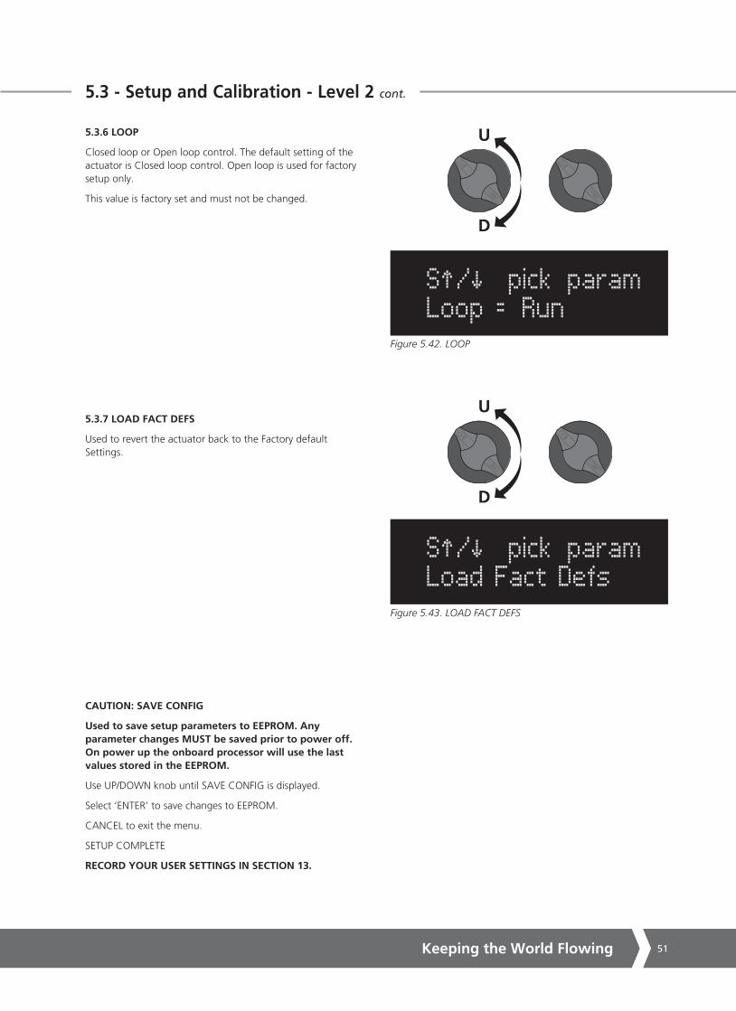
5.3.6 LOOP
Closed loop or Open loop control. The default setting of the actuator is Closed loop control. Open loop is used for factory setup only.
This value is factory set and must not be changed.
5.3.7 LOAD FACT DEFS
Used to revert the actuator back to the Factory default Settings.
CAUTION: SAVE CONFIG
Used to save setup parameters to EEPROM. Any parameter changes MUST be saved prior to power off. On power up the onboard processor will use the last values stored in the EEPROM.
Use UP/DOWN knob until SAVE CONFIG is displayed.
Select ‘ENTER’ to save changes to EEPROM.
CANCEL to exit the menu.
SETUP COMPLETE
RECORD YOUR USER SETTINGS IN SECTION 13.
D
U
Figure 5.43. LOAD FACT DEFS
S / pick param Load Fact Defs
5.3 - Setup and Calibration - Level 2 cont.
Figure 5.42. LOOP
S / pick param Loop = Run
D
U

SM6000 Series52
6 - Faults & Troubleshooting
6.1 FAULT STATUS INDICATION
Fault Diagnostics appear on line two of the display. When more than one diagnostic is active, only the highest priority will show.
Flt: Incr Limit
End of Travel Limit Switch for the increasing direction is tripped.
Decrease actuator position to move off limit switch.
Flt: Decr Limit
End of Travel Limit Switch for the decreasing direction is tripped.
Increase actuator position to move off limit switch.
Flt: Stalled
Actuator output speed is incorrect due to excessive load.
Momentary stall Flts are self-resetting.
Continuous or repetetive stall Flts indicate an improperly loaded actuator. Reduce load.
Flt: LOS-Command
Loss of command signal.
Command signal is below 3.6 mA, or above 21.6 mA.
Return command signal to 4-20 mA range.
Flt: Crnk Engagd
The hand crank has been engaged.
Pull out hand crank to remove Flt.
Flt: LOS-Feedbk
If using an encoder, either the encoder is disconnected, the encoder has reached the end of travel, or there is an internal encoder fault.
If using a potentiomer, the feedback pot has been disconnected or the feedback signal has risen above 4.9 V.
Flt: System Fail
Microprocessor has detected a system failure.
Simultaneously turn the UP/DOWN knob ACW and ENTER/ CANCEL knob CW to Clear the alarm.
Flt: Torq Limit
The current rating of the torque has been exceeded.
Simultaneously turn the UP/DOWN knob ACW and ENTER/ CANCEL knob CW to Clear the alarm.
Flt: Mtr Pol Re
Motor direction of operation or response is incorrect.
Motor leads possibly reversed.
Switch off and check motor wiring immediately!
Motor operation is checked automatically on power up.
C
U
Figure 6.1. Turn both knobs as shown to clear alarms.

Keeping the World Flowing 53
6 - Faults & Troubleshooting cont.
6.2 TROUBLESHOOTING
Trouble Possible Cause Remedy
Actuator will increase position but not decrease
LS2 is tripped Increase actuator to normal operating range. Check LS2 and Zero SetupActuator is at zero position
Actuator will decrease position, but not increase
LS1 is trippedDecrease actuator to normal operating range. Check LS2 and SPAN Setup
Actuator will not move
No actuator powerIs LED D1 on? If no, turn off electrical power and re-check electrical connections
Motor is not connectedConnect motor as shown in the wiring diagram
LS1 and LS2 are both tripped Verify LS1 and LS2 are setup correctly
Hand Crank engaged Remove hand crank engagement
Actuator oscillates during movement
Too high of proportional gain Reduce Cur P gain/CL gain
Actuator overshoots position Too high of integral gain Reduce Cur I gain
Poor response to command signal change
Too low of proportional gain Increase Cur P/CL gain
Amplifier defective Replace amplifier
Excessive noise on command signal
Reduce noise. Also ensure that command signal wiring is shielded with shield grounded at source common only
Actuator moves, but motor gets hot
Motor brake not disengaging Verify motor brake wiring
Motor brake module not setup Set per wiring diagram
Motor brake module defective replace phase control module
Actuator does not respond to a change in command
Wrong command type selected Verify current/voltage setup for command
Wiring disconnected Verify electrical connection
Actuator in Manual Place actuator in automatic
Actuator will not move and has lost feedback
Feedback element is disconnected
Check feedback device connection
Actuator position is out of operating range
Hand crank actuator to operating range
Nothing on DisplayNo Power to control/logic board
Is LED D1 on? If no, turn off electrical power and re-check electrical connections
Amplifier defective Replace amplifier
No Transmitter Output’
No power to TransmitterTransmitter is loop powered. See wiring diagram to supply isolated power to transmitter
Incorrect wiring Verify electrical connections
Transmitter ID defective Replace transmitter
Motor Runs but output shaft does not rotate
Motor Coupling defectiveVerify connection between motor and gear box
Actuator Back drives when power is removed
Holding brake improperly adjusted
Adjust spring force on holding brake
Holding brake worn Replace holding brake
Too heavy of a load Verify rating and load
Hand crank does not move output shaft
Hand crank not engaged fullyVerify hand crank couples with motor shaft
Hand crank retaining Pin worn or broken
Verify retaining pin
Motor coupling defectiveVerify connection between motor and gearbox

SM6000 Series54
7 - Local Operation - Handcrank Direction
10/370
10/550
10/800
10/1400
10/2500
10/4400
10/6200
12/8000
18/11000
26/16500
42/26000
CW
CW
CW
CW
CW
CW
CW
CW
CW
CW
CW
CW
CW
CW
CW
CW
CW
CCW
CCW
CCW
CCW
CCW
Speed/Torque Rotation of Handcrank
Rotation of Output Shaft (looking at the end of the output shaft)
Keeping the World Flowing 55
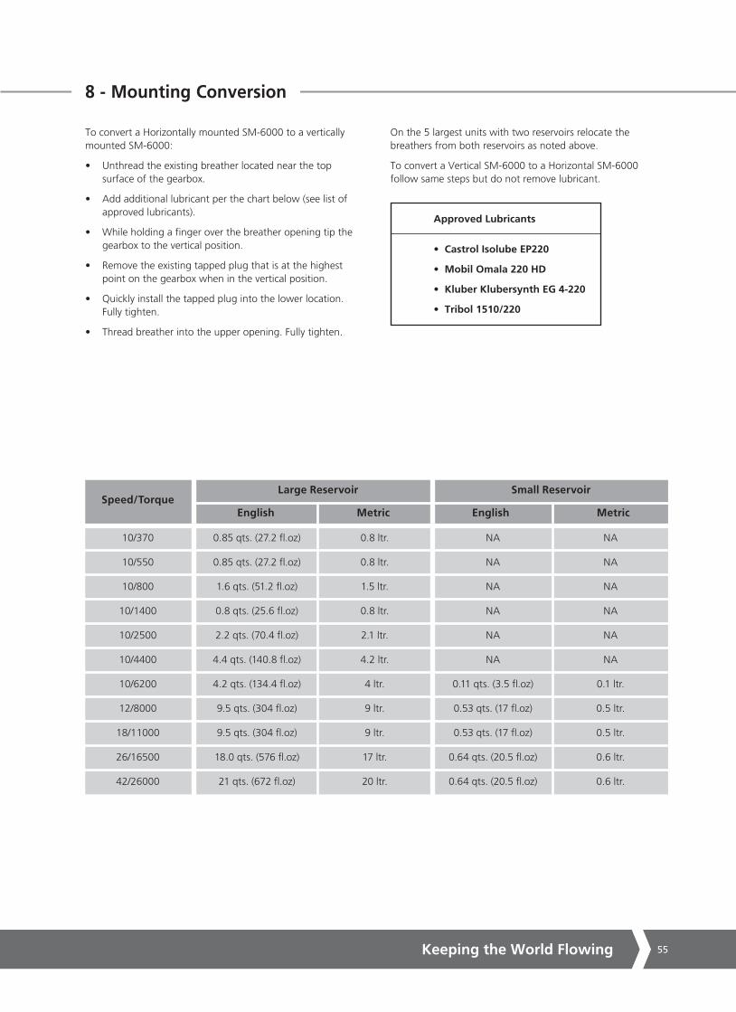
8 - Mounting Conversion
To convert a Horizontally mounted SM-6000 to a vertically mounted SM-6000:
• Unthread the existing breather located near the top surface of the gearbox.
• Add additional lubricant per the chart below (see list of approved lubricants).
• While holding a finger over the breather opening tip the gearbox to the vertical position.
• Remove the existing tapped plug that is at the highest point on the gearbox when in the vertical position.
• Quickly install the tapped plug into the lower location. Fully tighten.
• Thread breather into the upper opening. Fully tighten.
On the 5 largest units with two reservoirs relocate the breathers from both reservoirs as noted above.
To convert a Vertical SM-6000 to a Horizontal SM-6000 follow same steps but do not remove lubricant.
Approved Lubricants
• Castrol Isolube EP220
• Mobil Omala 220 HD
• Kluber Klubersynth EG 4-220
• Tribol 1510/220
10/370
10/550
10/800
10/1400
10/2500
10/4400
10/6200
12/8000
18/11000
26/16500
42/26000
0.85 qts. (27.2 fl.oz)
0.85 qts. (27.2 fl.oz)
1.6 qts. (51.2 fl.oz)
0.8 qts. (25.6 fl.oz)
2.2 qts. (70.4 fl.oz)
4.4 qts. (140.8 fl.oz)
4.2 qts. (134.4 fl.oz)
9.5 qts. (304 fl.oz)
9.5 qts. (304 fl.oz)
18.0 qts. (576 fl.oz)
21 qts. (672 fl.oz)
0.8 ltr.
0.8 ltr.
1.5 ltr.
0.8 ltr.
2.1 ltr.
4.2 ltr.
4 ltr.
9 ltr.
9 ltr.
17 ltr.
20 ltr.
NA
NA
NA
NA
NA
NA
0.11 qts. (3.5 fl.oz)
0.53 qts. (17 fl.oz)
0.53 qts. (17 fl.oz)
0.64 qts. (20.5 fl.oz)
0.64 qts. (20.5 fl.oz)
NA
NA
NA
NA
NA
NA
0.1 ltr.
0.5 ltr.
0.5 ltr.
0.6 ltr.
0.6 ltr.
Speed/TorqueLarge Reservoir
English EnglishMetric Metric
Small Reservoir

SM6000 Series56
48
370, 800 & 1400 ft. lb. units
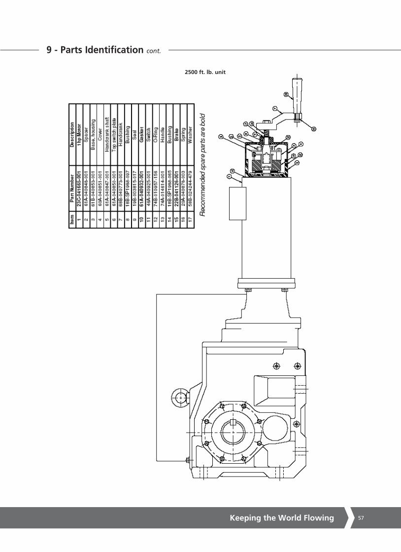
9 - Parts Identification
Keeping the World Flowing 57
9 - Parts Identification cont. 49
SM6000 publication P5XXE ver 1.02 24 Aug 09 revised for V3.08 Firmware
2500 ft. lb. unit

SM6000 Series58
50
SM6000 publication P5XXE ver 1.02 24 Aug 09 revised for V3.08 Firmware
9 - Parts Identification cont.
4400, 6200, 8000, 11000, 16500, & 26000 ft. lb. units
Keeping the World Flowing 59
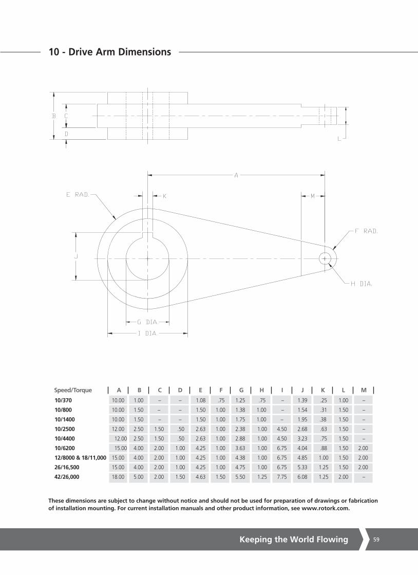
10 - Drive Arm Dimensions
10/370 10.00 1.00 – – 1.08 .75 1.25 .75 – 1.39 .25 1.00 –
10/800 10.00 1.50 – – 1.50 1.00 1.38 1.00 – 1.54 .31 1.50 –
10/1400 10.00 1.50 – – 1.50 1.00 1.75 1.00 – 1.95 .38 1.50 –
10/2500 12.00 2.50 1.50 .50 2.63 1.00 2.38 1.00 4.50 2.68 .63 1.50 –
10/4400 12.00 2.50 1.50 .50 2.63 1.00 2.88 1.00 4.50 3.23 .75 1.50 –
10/6200 15.00 4.00 2.00 1.00 4.25 1.00 3.63 1.00 6.75 4.04 .88 1.50 2.00
12/8000 & 18/11,000 15.00 4.00 2.00 1.00 4.25 1.00 4.38 1.00 6.75 4.85 1.00 1.50 2.00
26/16,500 15.00 4.00 2.00 1.00 4.25 1.00 4.75 1.00 6.75 5.33 1.25 1.50 2.00
42/26,000 18.00 5.00 2.00 1.50 4.63 1.50 5.50 1.25 7.75 6.08 1.25 2.00 –
Speed/Torque A B C D E F G H I J K L M
These dimensions are subject to change without notice and should not be used for preparation of drawings or fabrication of installation mounting. For current installation manuals and other product information, see www.rotork.com.

SM6000 Series60
11 - Overall Dimensions
D
K
J
F
GH
O M4 PLACES
L
O N SHAFT DIA.
O
PCOVER REMOVAL
E
I
C
B
A
Model A B C D E F G H I J K L M N O P
10/370 37.60 26.63 12.49 6.58 5.32 5.91 2.36 4.72 2.95 3.50 10.88 1.50 0.56Ø 1.250/1.249Ø 0.25 x 0.25 KEY 8.00
10/800 38.47 28.24 12.59 6.58 6.34 6.01 2.25 4.50 4.09 4.50 13.00 0.50 0.56Ø 1.375/1.374Ø 0.31 x 0.31 KEY 8.00
10/1400 39.24 30.17 14.41 6.58 7.72 7.84 3.25 6.50 4.47 5.38 14.50 0.75 0.81Ø 1.750/1.749Ø 0.38 x 0.38 KEY 8.00
10/2500 43.77 32.49 15.35 6.58 9.45 8.35 3.54 7.09 5.90 2.17 7.09 1.26 0.88Ø 2.375/2.374Ø 0.63 x 0.63 KEY 8.00
10/4400 53.83 35.64 18.78 6.58 11.42 10.43 4.72 9.45 6.69 2.95 9.45 1.50 1.02Ø 2.875/2.874Ø 0.75 x 0.75 KEY 8.00
10/6200 63.67 38.87 22.28 7.87 13.66 12.40 5.31 10.63 8.35 3.74 11.02 1.65 1.30Ø 3.625/3.624Ø 0.88 x 0.88 KEY 8.00
12/8000 71.23 42.84 29.09 8.86 16.45 14.76 6.50 12.99 9.96 4.53 13.78 1.77 1.54Ø 4.375/4.374Ø 1.00 x 1.00 KEY 8.00
12/11000 71.23 42.84 29.09 8.86 16.45 14.76 6.50 12.99 9.96 4.53 13.78 1.77 1.54Ø 4.375/4.374Ø 1.00 x 1.00 KEY 8.00
26/16500 73.79 45.87 32.40 9.84 17.99 17.72 8.27 16.54 9.72 5.51 14.96 1.97 1.54Ø 4.750/4.749Ø 1.25 x 1.25 KEY 8.00
42/26000 80.48 51.98 36.54 12.40 21.85 19.69 9.45 18.90 12.41 7.87 21.26 1.97 1.30Ø 5.500/5.499Ø 1.25 x 1.25 KEY 8.00
These dimensions are subject to change without notice and should not be used for preparation of drawings or fabrication of installation mounting. For current installation manuals and other product information, see www.rotork.com.

Keeping the World Flowing 61
12 - Linkage Options
Notes:
1. Maximum total linkage length is specified to prevent buckling under compressive load.
2. Special drive arm lengths are available to meet application requirements.
370 ft. lb.
2500 & 4400 ft. lb.
6200 & 16500 ft. lb.
800 & 1400 ft. lb.
Model“A” LENGTH
in. (mm)(See Note 3)
“B” MAXIMUMLENGTHft. (m)
“C” LENGTHin. (mm)
“D” LENGTHin. (mm)
“E” LENGTHin. (mm)
“F” DIA. HOLEmin.-max.in. (mm)
“G” PIPE SIZE
10 (254) 18 (5.5) 10 (254) 12.25 (311) 17 (432) 0.75 - 1.5(19 - 38.1)
1 - 2(25.4 - 50.8)
1.5 - 3.5(38.1 - 88.9)
2.5-5(63.5 - 127)
1 - 1/4 (NPT)
2 - 1/2 (NPT)
2 - 1/2 (NPT)
3 - 1/2 (NPT)
10 (254) 30 (9.1) 10 (254) 12.25 (311) 17 (432)
12 (305) 18 (5.5) 12 (305) 14.70 (373) 21.50 (546)
15 (381) 18 (5.5) 15 (381) 18.38 (467) 25.50 (648)

SM6000 Series62
13 - User Settings
Span
Zero
Max.Cal.:
Min. Cal.:
Speed:
Cmd Type:
Cntrl Mech:
Comms Settings:
LOS Action:
P Gain:
I Gain:
Min Pos
Max Pos
Max. Torque (%):
Max. Torque (ft. lbs.):
Input Volts (tp amp from transformer):
Motor Rating:
Password:
Loop: Open
Closed
CZero 0%:
CZero 25%:
CZero 50%:
CZero 75%:
CZero 100%:
Additional Information:

Keeping the World Flowing 63
Notes

USARotork Controls Inc.tel +1 (585) 247 2304fax +1 (585) 247 2308email [email protected]
PUB052-003-00Issue 02/17
Keeping the World Flowing
www.rotork.com
A full listing of our worldwide sales and service network is available on our website.
As part of a process of on-going product development, Rotork reserves the right to amend and change specifications without prior notice. Published data may be subject to change. For the very latest version release, visit our website at www.rotork.com
The name Rotork is a registered trademark. Rotork recognises all registered trademarks. The Bluetooth® word mark and logos are registered trademarks owned by Bluetooth SIG, Inc. and any use of such marks by Rotork is under license. Published and produced in the UK by Rotork Controls Limited. POWDG0217
UKRotork plctel +44 (0)1225 733200fax +44 (0)1225 333467email [email protected]
Rotork is a corporate member of the Institute of Asset Management


![PARALLEL HELICAL AND BEVEL HELICAL GEARBOXES · PARALLEL HELICAL AND BEVEL HELICAL GEARBOXES 7 4 RANGE AND DESIGNATION Size Output nominal torque M N2 [Nm] Transmission ratio Max](https://static.fdocuments.in/doc/165x107/5e20158e35e21d35cd60f074/parallel-helical-and-bevel-helical-gearboxes-parallel-helical-and-bevel-helical.jpg)