SLURRY SPRAYED THERMAL - University of Adelaide
90
_________________________________________________________________ SLURRY SPRAYED THERMAL BARRIER COATINGS FOR AEROSPACE APPLICATIONS _________________________________________________________________ Phuc Nguyen A thesis submitted in fulfilment of requirements for degree of Doctor of Philosophy School of Mechanical Engineering The University of Adelaide May 2010
Transcript of SLURRY SPRAYED THERMAL - University of Adelaide

_________________________________________________________________
SLURRY SPRAYED THERMAL
BARRIER COATINGS FOR
AEROSPACE APPLICATIONS
_________________________________________________________________
Phuc Nguyen
A thesis submitted in fulfilment of requirements
for degree of Doctor of Philosophy
School of Mechanical Engineering
The University of Adelaide
May 2010

Chapter 1 Introduction
1
CHAPTER 1
1 INTRODUCTION

Chapter 1 Introduction
2
1.1 Research Background
Thermal Barrier Coatings (TBCs) represent a relatively thin layer of a material with
high insulating properties, such as ceramics, that is bonded to a substrate, which is
usually a metal structure, to protect it during temperature excursions associated with
operating conditions or an accident. The application of TBCs can significantly
increase the operating temperatures for a number of practically important
applications, increase the efficiency and improve the durability of the structural
components and machine elements utilising thermal energy. There are many
applications, which have benefited from adopting TBCs, these include the
aeronautical aerospace, automotive and nuclear industries and heavy-duty utilities
such as diesel trucks [Koizumi, 1997; Padture, Gell and Jordan, 2002; Alhama and
Campo, 2003; Taymaz, 2007].
The development of TBCs has centred mostly on Partially Stabilised Zirconia (PSZ)
due to its unique physico-mechanical properties and has been led by its use in aircraft
engine combustion-path components. The significant advance in development of an
effective protective coating was associated with the development of Functionally
Graded (FG)–TBCs. FG–TBCs are multiphase composite materials that are
engineered to a have a spatial variation of material constituencies. Using FG–TBCs,
as an alternative to joining directly together two dissimilar materials such as
ceramics and metal, carries several advantages including: much lower thermal stress
distribution across the coating thickness; minimisation of stress concentrations at
interface corners; and an increase in bonding strength [Teixeira, 2001; Sahin and
Erdogan, 2004; Bialas, 2008].
There are many fabricating techniques for depositing ceramics or other coating
materials on metal substrates which have been developed over the past three decades,
[Niino, Hirai and Watanabe, 1987]. All fabricating techniques can be categorised in
three main groups: bulk processes, flame spray techniques and deposition techniques;
with each technique differing from each other greatly, in terms of physical principal
used, cost and simplicity [Kieback, Neubrand and Riedel, 2003]. However, the main

Chapter 1 Introduction
3
obstacle in the widespread application of these techniques is usually a relatively high
cost of fabrication of TBCs, which include the use of sophisticated equipment and
need for highly trained personnel. Moreover, many of these techniques are not
applicable to cover large or curved areas. All these drawbacks formed the main
motivation for the current project.
The objective of this research is to develop and investigate a relatively simple and
cost effective technique for fabricating TBCs including FG-TBCs with the focus on
aeronautical and aerospace applications. This new technique is based on a traditional
Wet Powder Spray (WPS) technique and can be divided into four separate stages: (1)
slurry mixing, (2) spraying, (3) pressure stamping, (4) evaporation and sintering.
Previous studies have indicated that despite being very promising for a number of
industrial applications the quality of the fabricated coating utilizing the traditional
wet spray method is normally significantly lower than that obtained by other
methods in terms of fracture resistance and durability. Therefore, a significant effort
in the current research is directed to the characterisation and improvement of the
WPS technique to achieve a high quality TBC and make the modified method
suitable for the fabrication of thermal protection in various applications. The current
work includes the development of a new manufacturing procedure, extensive testing
of the mechanical and thermal properties of the manufactured coating, optimisation
of the fabricating parameters using experimental and theoretical approaches and a
numerical validation study.
The experimental approach includes a set of mechanical and thermal test procedures
as well as microscopic investigations to comprehensively characterise the quality of
the coating and understand the effect of various fabrication parameters and
composition on the fracture resistance, durability and apparent properties of the
coatings. At the final stage of the research, full-scale tests simulating the loading
conditions corresponding to aerospace applications were conducted to obtain the
overall assessment of the applicability of this technique in aerospace engineering.
The theoretical approach includes a multi-scale modelling of thermal field and
thermal stresses in FG–TBCs. The thermal stress is generally recognised to be the

Chapter 1 Introduction
4
major factor responsible for mechanical failure of the coating. The aim of the
mathematical modelling was to understand the effect of fabrication parameters on the
intensity of the thermal stresses induced due to temperature excursion and to guide
the optimisation study to improve the overall quality of the coatings and produce the
technique as a cheap and robust alternative to the existing methods, which are
normally quite expensive and have many limitations.
1.2 Research Significance
Thermal Barrier Coatings (TBCs) are essential structural components in current
engineering applications associated with high temperatures or high thermal fluxes as
well as in future developments. These include thermal protection for rocket and
scramjet engines, re-entry space vehicles, gas turbines, diesel engines, nuclear power
plants and many other structures and machines.
Currently there are a number of well developed manufacturing techniques available
for fabricating TBCs including FG coatings. However, the main obstacle in the
widespread application of these techniques is a relatively high cost of fabrications
and equipment. For example the setup costs of Plasma Spray facilities start in the
millions of dollars. Moreover, many of these techniques are not applicable to cover
large, like in aerospace applications or produce FG–TBCs to increase the reliability
and improve the resistance to mechanical failures. All these drawbacks formed the
main objective of the current research.
From the above discussion it follows that the research and development of a new low
cost fabricating technique, which is the major objective of the current project,
represents a significant contribution in a number of current engineering applications
utilizing or experiencing high temperatures or temperature gradients as well as for
future developments focused on the achievement of high thermal efficiency and
performance.

Chapter 1 Introduction
5
1.3 Research Objectives
The primary objective of this research is the development of a relatively simple, cost
effective technique with acceptable quality coating for fabricating TBCs with the
focus on aeronautical and aerospace applications. The specific research objectives
are as follows:
Development of a new, low-cost and effective fabricating technique for
manufacturing FG–TBCs.
Development of standardised experimental techniques for comprehensive
characterisation of the manufactured TBCs to determine thermo-mechanical
properties of the Slurry Based Technique.
Analysis of manufacturing parameters on the mechanical failure of the coatings
based on the combined experimental investigations and theoretical modelling.
Optimisation study with the main focus to improve significantly the fracture and low
cycle fatigue resistance of the TBCs.
Scale testing of Slurry based TBCs in high temperature and high temperature
gradient environments corresponding to a hypersonic flight.
Validation study utilising the micro-mechanical modelling and the Finite Element
Analysis (FEA).
1.4 Outline of Thesis
Chapter 1 gives an introduction to the research topic and presents the statement of
significance and objectives of the research conducted and concluded with outline of
the thesis.
Chapter 2 gives an in depth literature review of the research backgrounds of the

Chapter 1 Introduction
6
current research topic. These include the current and future applications of Thermal
Barrier Coatings, the material aspects of TBCs and the primary properties, and the
different fabricating techniques, such as flame spray and deposition techniques.
Chapter 3 presents the Slurry Spray Technique for fabricating FG–TBCs, newly
developed at the University of Adelaide. The chapter focuses on the development
and improvement of this technique, with the focus on coating adherence and
survivability in comparison to the other traditional techniques for fabricating TBCs.
Chapter 4 presents the experimental investigation of the Slurry Based TBCs. These
experiments consist of standard thermo-mechanical tests including adhesion strength,
thermal cycling, thermal conductivity, Vickers micro hardness tests as well as
Scanning Electron Microscopy. These experiments aim to understand the effect of
various fabrication parameters and composition on the quality and effective
properties of the coatings, as well as characterise the TBC
Chapter 5 presents the development of a new test rig for scale tests simulating the
thermal loading conditions corresponding to the high temperature aerospace
applications. These experiments were conducted to obtain an overall assessment of
the applicability of this technique to produce TBCs for such sort of applications. The
test rig was based on a new concept and utilised a flat burner for generating the high
temperatures and temperature gradients.
This chapter also presents the outcomes of a virtual testing of the TBCs fabricated
with the new technique. This testing was conducted to evaluate the efficiency of
TBCs in conditions relevant to the hypersonic flight.
Chapter 6 presents the overall conclusions of the conducted research, along with
recommendations for future work.

Chapter 1 Introduction
7

Chapter 1 Introduction
8

Chapter 2 Background and Literature Review
9
CHAPTER 2
2 BACKGROUND AND LITERATURE REVIEW

Chapter 2 Background and Literature Review
10
2.1 Introduction
This literature review is comprised of three sections. The first section is dedicated to
the current and potential applications of Thermal Barrier Coatings (TBC) focusing on
the aeronautics and aerospace industry. Particular attention is paid to Functionally
Graded Thermal Barrier Coatings (FG–TBCs). This type of coating shows
considerable promise for many current high-temperature applications as well as
future developments.
The second section of this chapter is devoted to the materials aspect of TBCs. Low
thermal conductivity, high melting point and good resistance against oxidation and
corrosion are all mandatory properties for materials used for TBCs. The material
which satisfies all these requirements is widely accepted as engineered ceramics.
Many types of ceramics have been investigated in the past, however, the major
development of TBCs is focused on Yttria Stabilised Zirconia (YSZ) [Clarke and
Phillpot, 2005], due to its unique mechanical and physical properties, which will be
critically discussed in this part of the literature review.
In the final section of the literature review, current techniques for manufacturing and
fabricating TBC are discussed in detail. The existing TBC techniques can be
separated into three main groups: bulk processes, flame spray processes and
deposition processes. Each group has its own distinct advantages and disadvantages,
however, all the reviewed manufacturing techniques result in high cost of fabrication
for TBC, complex process setups, and many of them are not applicable to cover large
areas. The current research is mainly driven by these drawbacks, with the main
objective to develop a new, simple and cost effective technique for manufacturing
TBC including functionally graded coatings applicable to cover curved and large
areas, which is specifically very important for future aerospace projects such as a
hypersonic scramjet project.

Chapter 2 Background and Literature Review
11
2.2 Background – Applications
A Thermal Barrier Coating (TBC) is a relatively thin layer of a material with high
insulating properties, which is bonded to a substrate to protect the metal load
carrying structure during temperature excursions. The material used as the thin layer
is usually a ceramics, with the substrate usually being a metal structure. The
application of TBCs can significantly increase the operating temperatures up to
1400-1500ºC, increase efficiency of thermal processes and improve the durability of
the components. TBCs were originally developed for aerospace and power industry
applications. Currently, there are many other applications, which benefit from
adopting TBCs. These include applications in the automotive and nuclear industry
and heavy-duty utilities such as diesel trucks.
2.2.1 Aerospace and Aeronautical Applications
TBC were originally designed for use in turbine engines, and are currently finding
increased use in applications such as aeronautics, specifically in rocket and scramjet
engines [Toriz, Thakker and Gupta, 1989]. The duration of a mission cycle for an
aero gas turbine engine is typically several hours, although maximum gas
temperatures occur only for a matter of minutes during takeoff and landing [Abdul-
Aziz, Tong and Kaufman, 1989]. Repeated mission cycles result in thousands of
hours of operation between engine overhauls, with hundreds of hours being spent at
peak temperatures. The rocket combustors normally experience much higher thermal
loading than ground based turbines [Feuerstein, Knapp, Taylor, Ashary, Bolcavage
and Hitchman, 2008]. Traditional TBCs used in ground based turbines are usually
not able to cope within the hostile environments of much higher temperatures and
temperature fluxes experienced by air turbines. In many TBC applications, stresses
due to the difference in thermal expansion of the coating and the substrate can have a

Chapter 2 Background and Literature Review
12
detrimental effect on the service life and safety of the component leading to
mechanical damage of the protective coating, such as spallation and cracking of the
coating [Mao, Dai, Yang and Zhou, 2008].
One effective way to reduce the adverse effect of thermal stresses is to use
Functionally Graded Thermal Barrier Coating (FG–TBCs), where thermal and
mechanical properties vary gradually through the thickness. In metal-ceramic FG–
TBCs, the ceramic-rich side is exposed to high heat fluxes from high temperature
applications. FG–TBCs are fabricated by directly joined together two dissimilar
materials, such as ceramic and metal powders, which are applied to a metal substrate
[Tamura, Takahashi, Ishii, Suzuki, Sato and Shimomura, 1999]. FG–TBCs have
many advantages over non graded TBC, for example these include minimisation or
elimination of stress concentrations, reduction of thermal stresses and singularities at
the interface corners. These advantages lead to the significant increase in the strength
and durability of the TBC [Koizumi, 1997]
2.2.2 Space Re-entry
Space vehicles travelling at hypersonic speeds, experience extremely high
temperatures from aerodynamic heating due to friction between the surface of the
vehicle and the atmosphere. Two types of space vehicles are categorised in this
section, the US space shuttles used for Apollo missions launched into space by a
vertical propulsion system and reusable spacecraft, which are based on horizontal
take off either from a ground based runway or horizontally flying carrier.
During re-entry, space vehicles travel at speeds of excess of 11 km/s [Miyamoto,
Kaysser, Rabin, Kawasaki and Ford, 1999]. At this stage the leading edges of the
vehicle rapidly heat up to where the heat protection reaches temperatures of up
2500°C. For example, if the space re entry vehicle is at an altitude of 120 km, re-
entry velocity may reach speeds of up to 8 km/s, where the temperatures may reach
up to 1500°C for a few minutes [Miyamoto, Kaysser, Rabin, Kawasaki and Ford,

Chapter 2 Background and Literature Review
13
1999]. The structural components that experience the highest amount of heat are the
leading edges of the vehicles, for example, nose cones and rudders which are
constructed of carbon/carbon composites. Other areas of the space craft where the
temperatures are not as extreme (only up to 1200°C), ceramic tiles are used. For
temperatures ranging from 300 – 550°C, TBC based upon Ti sheets are used for
thermal protection [Koizumi, 1997].
2.2.3 Rocket Combustors
It has been demonstrated that the thermal performance of rocket engines may be
improved significantly by increasing the tolerance of the metallic walls of the nozzle
from the impact of the ultra-high temperatures produced by the stream of turbulent
combustion gases emerging from the combustor [Peters, Leyens, Schulz and
Kaysser, 2001]. One feasible approach for achieving ultra-high operating
temperatures in the combustor without damaging the structural integrity of the
metallic substrate of the nozzle wall is concerned with the application of a ceramic
coating to the exposed surface of the nozzle wall. The ceramic coating creates an
artificial thermal barrier which retards the heat flow from the stream of turbulent
combustion gases to the metallic substrate [Alhama and Campo, 2003].
Previous studies of Chemical Vapour Deposition (CVD) technique show that
manufactured Silicon Carbide/Carbon (SiC/C) Functionally Graded Thermal Barrier
Coatings (FG–TBCs) were used for rocket combustor tests with nitrogen tetroxide
and monomethyl hydrazine propellants, with firing cycles of 55 seconds
[Wakamatsu, Saito, Ono, Ishia, Matsuzaki, Hamamura, Sohoda and Kude, 1997].
The maximum outer wall temperature measured, ranged from 1376 – 1527°C, while
the inner wall temperatures reached 1677°C – 2027°C. With the protection provided
from the TBC, no damage to the combustors was observed.
Chapter 2 Background and Literature Review
14
2.2.4 Gas Turbines
TBCs are used for military and commercial aeroengines as well as for gas turbine
engines for automobiles, helicopters and marine vehicles [Nicholls, 1991; Pichon,
Lacoste, Barreteau and Glass, 2006]. TBC are predominately used in areas where the
hot gas ways are located, to increase the operating temperature of the structure
[Gurrappa and Sambasiva, 2006]. TBC in gas turbines operate at a higher heat flux
and higher temperature range than diesel engines, as well as being subjected to hot
corrosion and erosion. For these applications, TBCs generally have relatively thin
coating thickness in the order of less than 400 �m, to reduce the possibility of
spalling [Duvall and Ruckle, 1982].
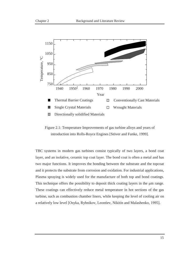
The temperature improvements of gas turbine alloys and coated alloys as a function
of the year of introduction are shown in Figure 2.1. In the majority of these cases, the
improvement of mechanical strength and creep properties at high temperatures is
connected with a decrease of oxidation resistance. With temperatures above 1100 °C
the super alloys have to be protected against oxidation and the mechanical strength
becomes critical, against high temperatures [Padture, Gell and Jordan, 2002].
Chapter 2 Background and Literature Review
15
Figure 2.1: Temperature Improvements of gas turbine alloys and years of
introduction into Rolls-Royce Engines [Stöver and Funke, 1999].
TBC systems in modern gas turbines consist typically of two layers, a bond coat
layer, and an isolative, ceramic top coat layer. The bond coat is often a metal and has
two major functions. It improves the bonding between the substrate and the topcoat
and it protects the substrate from corrosion and oxidation. For industrial applications,
Plasma spraying is widely used for the manufacture of both top and bond coatings.
This technique offers the possibility to deposit thick coating layers in the �m range.
These coatings can effectively reduce metal temperature in hot sections of the gas
turbine, such as combustion chamber liners, while keeping the level of cooling air on
a relatively low level [Osyka, Rybnikov, Leontiev, Nikitin and Malashenko, 1995].
1950 1960 1970 1940 1980 1990 2000
Tem
pera
ture
, °C
750
850
950
1050
1150
Directionally solidified Materials
Single Crystal Materials
Thermal Barrier Coatings Year
Wrought Materials
Conventionally Cast Materials

Chapter 2 Background and Literature Review
16
2.2.5 Nuclear Industry
The evaluation of materials for nuclear waste disposal or transmutation lay in several
specific and highly desirable advantages. From studies by [Thomé and Garrido,
2001], the advantages include:
• high melting point
• good thermal conductivity
• absence of phase transformation at high temperatures
• stability against radiation
• good mechanical properties
• oxidation resistance
• low solubility in water
• retention of radiotoxic elements
• adequate neutronic properties
Yttria Stabilised Zirconia (YSZ) is considered an attractive matrix for nuclear
applications, such as inert matrix for the destruction of excess plutonium or good
host materials for nuclear waste storage [Degueldre, 2007]. This high temperature
refractory oxide is attractive because it presents a high radiation stability, a high
melting point, a small neutron capture cross section, and an ability to form solid
solutions with a wide range of solubility for actinide elements such as Plutonium,
Uranium and Thorium [Menvie Bekale, Legros, Haut, Sattonnay and Huntz, 2006].

Chapter 2 Background and Literature Review
17
2.2.6 Diesel Engines
In diesel engine applications, ceramic coatings hold significant promise in the
reduction of wear and abrasion failure in reciprocating and rotary engines for
transportation and stationary power. TBCs are also employed in diesel engines for
trucks, buses, marine vehicles, tanks, military transport vehicles and farm vehicles
[Levy and Macadam, 1987; Hejwowski and Weronski, 2002; Taymaz, 2007]. They
also have application as thermal barriers to improve the efficiency of the engines, by
reducing energy loss and cooling requirements [Taymaz, 2007]. In addition to the
insulating attributes, TBCs improve combustion efficiencies through surface catalytic
and emissivity effects of the ZrO2 layer on combustion zone components. The
improvement in the efficiency ranges from 7 to 9 %, as reported from numerous
studies conducted, was normally achieved in the ceramic-coated diesel engines in
comparison with the similar uncoated diesel engines [Lackey, Stinton, Cerny,
Schaffhauser and Fehrenbacher, 1987]. This performance gain could potentially be
increased to an overall thermal efficiency of 54 % for advanced diesel concepts, with
FG–TBCs showing an increase in the lifetime of diesel engines [Uzun, Çevik and
Akçil, 1999; Taymaz, 2007]. These added benefits increase the potential for wider
commercial use in diesel engine applications.
2.2.7 Future Gas Turbine Systems
TBCs will play a crucial role in advanced gas turbine engine systems because of their
ability to significantly increase engine operating temperature and reduce cooling,
thus greatly helping to achieve low emission and high efficiency goals. Under the
NASA Ultra Efficient Engine Technology (UEET) program, advanced TBC systems
are being developed to provide vital thermal protection for components such as
combustor liner and vanes, for gas temperatures exceeding 1760°C in harsh oxidising
and water vapour containing combustion environments of the turbine engines. Higher
operating temperatures of turbine engines result in significant improvements in fuel

Chapter 2 Background and Literature Review
18
consumption, efficiency, and emissions [Bansal and Zhu, 2008]. The temperature
gradient projected for a TBC system for future advanced turbine systems, is shown in
Figure 2.2.
Figure 2.2: Temperature Gradient over a TBC-coated substrate [Padture, Gell and
Jordan, 2002]
a1172507
Text Box
NOTE: This figure is included on page 18 of the print copy of the thesis held in the University of Adelaide Library.
Chapter 2 Background and Literature Review
19
2.3 TBC Structure, Performance and Materials
2.3.1 Introduction
The development of TBCs has centred on Partially Stabilised Zirconia (PSZ) and has
been led by its use in aircraft-engine combustion-path components. PSZ is a unique
material used for many applications including engineering ceramics, TBCs, ceramic
implants, electro ceramics, high-temperature magnetohydrodyhamic electrodes, fuel-
cells, and oxygen sensors. This variety is grounded on use of a combination of
mechanical, electrical, thermal and other properties which will be considered in this
section [Beele, Marijnissen and van Lieshout, 1999].
The structure of ZrO2 (Zirconia) when heated above 1000°C changes from
monoclinic to tetragonal, the accompanying volume changes of 4 to 6 % can result in
severe spalling of the ceramic layer. Therefore, PSZ coatings, made from ZrO2
alloyed with stabilising oxides such as Y2O3, CeO2 and MgO, are used. Typical state-
of-the-art TBC utilise ZrO2 partially stabilised with 6-8 %wt Y2O3 [Duvall and
Ruckle, 1982]. The materials have been found to be best when deposited on a
metallic bond coating [Meier and Gupta, 1994]. Chromium and Aluminium elements
are added to the bond coat, and traces of Yttrium are added to form dense, well-
adhered, protective sub-TBC oxide scales. The smooth transition of the bond layer’s
Coefficient of Thermal Expansion (CTE) between that of the base metal and that of
the TBC (Y2O3 – ZrO2) is generally accepted to reduce the thermal stresses produced
during coating application and service thermal cycling [Teixeira, Andritschky,
Fischer, Buchkremer and Stöver, 1999].
Low thermal conductivity, high melting point and good resistance against oxidation
and corrosion are the required advantages of ceramic coatings applied in high
temperature applications. However, compared to metals, ceramics are not reliable
with respect to mechanical properties. This non-reliability hinders the use of bulk
ceramic parts in turbines and diesel engines, despite intensive research on structural
ceramics. Instead, the advantages of ceramics and metals are combined by utilising

Chapter 2 Background and Literature Review
20
ceramic thermal barrier coated metallic substrates. Extremely low thermal
conductivity and phase stability makes Yttria-Stabilised Zirconia the most successful
ceramic top-layer, when combined with a metallic interlayer, as this interlayer acts
both as a bond coat and as an oxidation and corrosion protection barrier. The alloy
normally consists of a base of Molybdenum, Nickel, Cobalt and/or Iron, Chromium,
Aluminium, Yttrium and additional active elements such as Silicon, Titanium and
Rhenium. The bond and top coat can be applied by thermal spraying or by vapour
deposition techniques. The limited life-time of the TBC system forms the boundary
of this 40-year-old concept [Troczynski, Cockcroft and Wong, 1996]. Until the past
decade, the use of TBC on aircraft turbines blades was not design-integrated. The
TBCs are used frequently to lower the metal temperature, and therefore elongate the
life-time of a blade itself. If the coating spalls off, metal temperature will increase,
but not above a critical point. For design-integrated TBC with improvement of
efficiency, fuel consumption and exhaust pollution, 100% reliability is necessary.
The life-time of various TBC systems as a function of the operating temperatures
against cycles to failure is illustrated in Figure 2.3. For lower temperatures of 960°C
or less, the single layered TBC systems have comparable life spans with the double
layered coating systems. However, with the increase in temperature, the life span of
the single layered coating decreases significantly, with the double layered coating
exhibiting superior levels of life span at higher temperatures.

Chapter 2 Background and Literature Review
21
Figure 2.3: Cycles to failure for different TBC systems. [Vaßen, Kaßner, Stuke,
Hauler, Hathiramani and Stöver, 2008]
Double layer
Double layer
Single layer La2Zr2O7
10
100
1000
10000
1250 1300 1350 1200 1400 1450
Cyc
les t
o Fa
ilure
T high (> 960°C)
T low (< 960°C)
Tsurface, °C
Double layer
Lifetime range of standard Lifetime range of double layer

Chapter 2 Background and Literature Review
22
2.4 Material Properties
2.4.1 Modulus of Elasticity
The modulus of elasticity is an important material property which determines the
stress levels in the coating during fabrication and usage. The spallation resistance is
also greatly affected by the modulus of elasticity. At high temperatures, the modulus
of elasticity changes significantly due to the sintering densification technique [Zhu
and Miller, 2000]. Typical values of the modulus of elasticity used for TBC range
from 21 to 175 GPa, depending on the performance requirement of the coating. The
typical values of modulus of the elasticity of various materials can be found in Table
2.1 [Kokini, Takeuchi and Choules, 1996; Mesrati, Ajhrourh, Du and Treheux, 2000;
Vassen, 2000].
2.4.2 Thermal Conductivity
The thermal conductivity of a TBC is one of the most important material properties
governing the effectiveness of the coating to shield substrates from high temperature
experiences. Thermal conductivity governs heat conduction from the top layer of a
TBC to the structural material. As a result, thermal conductivity of TBC is an
important parameter to accurately compare the effectiveness of the coating produced
using different manufacturing methods and materials. Values of thermal conductivity
for ceramic coatings range from 2 to 9 W/mK [Padture and Klemens, 1997; Mesrati,
Ajhrourh, Du and Treheux, 2000; Vassen, Stuke and Stöver, 2009]. It was found that
in the fabricated TBC thermal conductivity gradually increases throughout the
thickness of the coating [Miller, Leissler and Jobe, 1993].

Chapter 2 Background and Literature Review
23
2.4.3 Coefficient of Thermal Expansion
The thermal expansion is an important characteristic which affects mechanical
behaviour in severe thermal environments such as gas turbines and space structures.
The Coefficient of Thermal Expansion (CTE) of a material is defined as the linear
expansion of strain per unit of temperature change. Typical values of CTE for
various coating materials can be seen in Table 2.1. The thermal expansions of
metal/ceramic coatings have been studied extensively in order to optimise the graded
compositions through relaxation of thermal stresses [Lee, Miller and Jacobson, 1995;
Padture and Klemens, 1997; Cao, Li, Zhong, Zhang, Zhang, Vassen and Stoever,
2008].
2.4.4 Materials for Thermal Barrier Coatings
The most important component of a TBC material is the ceramic used to supply the
bulk material properties for the coating. Ceramics are ideally suited for use as TBCs
due to their high melting temperatures, toughness and typically low thermal
conductivity [Choi, Zhu and Miller, 2005]. Ceramics adopted for fabricating coatings
using the Slurry Spray Technique (discussed in section 3.3) also require additional
material properties to be used successfully. These additional material properties
include availability as a sinterable powder, resilience to thermal fatigue, ability to be
dispersed within a liquid and resistance to corrosion.

Chapter 2 Background and Literature Review
24
Table 2.1: Properties of TBC Materials
Zirconia Garnet Ceramics Mullite La2ZrO7
Melting Temperature, °C 2700 1970 1850 2300
Thermal Conductivity, W/mK 2.0 3.0 3.3 1.6
Modulus of Elasticity, GPa 21
not applicable
30 175
CTE, (x 10-6) 1/°C 15.3 9.1 5.3 9.1
Poisson’s Ratio 0.25 not
applicable 0.25
not applicable
Yttria Stabilised Zirconia
The extensive use of Yttria Stabilised Zirconia (YSZ) in current TBC applications is
due to the ability to be deposed using many existing technologies such as Low
Velocity Oxygen Flame (LVOF) spray technique or Atmospheric Plasma Spray
(APS) [Kim and Kweon, 1999; Tamura, Takahashi, Ishii, Suzuki, Sato and
Shimomura, 1999; Lima and Guilemany, 2007]. The use of Yttria as the stabiliser for
Zirconia (ZrO2) in the ceramic compound is very beneficial for the quality of the
coating and was confirmed through numerous mechanical experimental
investigations and full-scale testing [Khor, Dong and Gu, 1999; Dobbins, Knight and
Mayo, 2003; Clarke and Phillpot, 2005]. YSZ offers the most reliable performance in
high temperature applications and the common use of this ceramic compound
provides a vast amount of information making it a standard coating material in most
TBC applications. However, the main disadvantage of YSZ is the inability to
withstand temperatures higher than 1200°C for prolonged use and phase
transformations of the material structure at temperatures greater than 1170°C [Cao,
Vassen and Stoever, 2004].

Chapter 2 Background and Literature Review
25
The stabilisation of Zirconia describes the addition, or doping, of Zirconia with a
metal oxide addition to increase the resilience of Zirconia to stresses introduced
during cooling after exposure to high temperatures. These stresses are the result of
phase changes within the Zirconia microstructure as thermal energy is dissipated.
During cooling from temperatures less than 1200°C, the unstabilised Zirconia
undergoes a phase change from cubic to monoclinic phase. Transition between these
two phases results in a 3 % volume reduction, which in turn produces tensional
stresses within the Zirconia microstructure. These tensional stresses then proceed to
enhance crack propagation along grain boundaries within the Zirconia microstructure
and ultimately result in universal fracture and failure [Mao, Dai, Yang and Zhou,
2008].
Stabilisation of the Zirconia through the addition of small quantities of metal oxide
prohibits the phase change of Zirconia between monoclinic and cubic phases.
Therefore stresses associated with this phase change are reduced. A common metal
oxide addition used to stabilise Zirconia is yttria, which is typically used to dope the
Zirconia in concentrations between 1 – 8 % wt [Majumdar and Jana, 2000].
Mullite
Mullite represents an important material for use in TBC applications. Mullite is low
density, has high thermal stability, maintains stability in severe chemical
environments, has low thermal conductivity and favourable creep strength
[Torrecillas, Calderón, Moya, Reece, Davies, Olagnon and Fantozzi, 1999; Brunauer,
Frey, Boysen and Schneider, 2001]. Mullite is a composed of SiO2 and Al2O3, with
the composition of 3SiO2 + 2Al2O3. In comparison to YSZ, Mullite has a much lower
CTE, and higher thermal conductivity, as seen in Table 2.1, and has the advantage of
being more resistant to oxidation. Mullite is an attractive alternative to YSZ for
applications in diesel engines, where the temperatures are much lower than gas
turbine engines; however, the temperature variations are much larger. Tests have
shown that Mullite coatings in diesel engines have a longer lifespan than YSZ
[Kokini, Takeuchi and Choules, 1996; Gilbert, Kokini and Sankarasubramanian,

Chapter 2 Background and Literature Review
26
2008]. However, the thermal cycling life of Mullite has been found to be much
shorter than the YSZ when temperatures exceed 1000°C. At this temperature, Mullite
crystallises, which is followed by volume contraction, causing cracking and
spallation of the TBC [Rendtorff, Garrido and Aglietti, 2008].
Yttrium Aluminium Garnet (YAG) - Y3Al5O12
Garnet ceramics was developed as a TBC material, as shown in [Padture and
Klemens, 1997]; YAG (Y3Al5O12) exhibiting superior mechanical performance in
high-temperature applications, outstanding thermal stability up to the high melting
point of 1970°C and low thermal conductivity (in the order of < 3 W/mK) [Clarke
and Phillpot, 2005]. It also has a significantly lower oxygen diffusivity coefficient
compared to pure Zirconia, implying higher resistance towards oxidation. However,
the relatively large value of the CTE of 9.1 x 10⁻⁶ 1/°C has posed severe limitations
in the use of this material in many practical applications [Cao, Vassen and Stoever,
2004].
LZ – La2ZrO7
LZ is a promising material for use as a TBC, due to its excellent physico-mechanical
properties and microstructure [Cao, Li, Zhong, Zhang, Zhang, Vassen and Stoever,
2008]. The LZ has a cubic pyrochlore structure, making LZ phase stable up to its
melting temperature. With this feature, LZ is an attractive material for use as a TBC
and also has a thermal conductivity which is lower than that of YSZ [Clarke and
Phillpot, 2005]. Another advantage is that LZ has relatively low sintering
temperature in comparison to other ceramics. However, the main disadvantage of the
coating material is the relatively short thermal cycling life, due to the relatively low
CTE and low fracture toughness [Cao, Vassen, Tietz, Jungen and Stoever, 2001].

Chapter 2 Background and Literature Review
27
Partially Stabilised Zirconia
Yttria Partially Stabilised Zirconia (PSZ) powder TZ-3Y-E produced by Tosoh,
Tokyo, Japan has been used for coating development. TZ-3Y-E is a mixture of
partially-stabilised Zirconia powder with 3 mol% yttria which exhibits superior
sintering properties and higher aging resistance at lower sintering temperature of
1350ºC [Tosoh, 2008]. PSZ has a density of 6050 Kg/m3, thermal conductivity of 2.2
W/mK, and melting point of 2680ºC [Yoshida, 2005]. PSZ has an average particle
size of 0.6 microns [Antou, Hlawka, Cornet, Montavon, Coddet and Machi, 2004].

Chapter 2 Background and Literature Review
28
2.5 Fabricating Methods
2.5.1 Introduction
There exist many methods of joining and fabricating Functionally Graded Thermal
Barrier Coatings (FG–TBCs). These fabricating methods can be separated into three
categories: Bulk Processes, Flame Spray and Deposition techniques. Each technique
differs greatly from one another, in terms of fabricating method, cost and simplicity.
The following section provides an overview of the processing techniques available
for fabricating TBC.
2.5.2 Bulk Processes
Powder Stacking
Bulk processing of ceramic coatings by powder stacking involves the following
sequential steps with the selection of ceramics and metals, as seen in Figure 2.4.
Initially the depositions of powders on each layer are of a different composition,
which is then compacted and sintered.

Chapter 2 Background and Literature Review
29
Figure 2.4: Processing steps in fabrication of ceramic coatings
The deposition can be done under normal gravity, centrifugal forces and applied
pressure [Leushake, Winter, Rabin and Corff, 1999]. The multi-layered powder
configurations contain discrete compositions in each layer, and stepwise change in
composition from each layer to the next.
The compacting and sintering behaviour varies from layer to layer. If this variety is
not taken into consideration different sintering behaviour will cause various localised
sintering faults, which include warping, necking, splitting and crack formation. The
sintering behaviour is controlled by the following three parameters of the shrinkage
curve: the onset temperature of shrinkage, the slope of shrinkage curve as a function
of temperature and the integral net shrinkage [Watanabe, 1995].
(1) Select Powder
(3) Mix Intermediate Compositions
(2) Add sintering Aids for ceramic
(4) Lay powders in die
(5) Compaction
Sintering Hot Press

Chapter 2 Background and Literature Review
30
Laminate Sheet Stacking
With more advanced techniques, thin sheet lamination can be formed from powder
slurries, to form 100 to 1500 �m thick coating [Jin, Takeuchi, Honda, Nishikawa and
Awaji, 2005]. The thin sheets are produced by laminating or stacking these layers
with different compositions, as shown in Figure 2.5. Mixtures of these compositions,
usually with Zirconia and Nickel powder, are processed into slurries containing
binder, deflocculate and plasticiser additives. Air and excess water are then removed
by evaporation before film casting. Next the individual sheets are stacked by pressing
them together, followed by drying of the stack with slow heating using a low
temperature oven, which is followed by sintering. The green sheets are able to be
moulded and formed into various geometries. The number of sheets would be limited
mainly by costs of the fabrication process [Zhang, Han, Zhang, He, Li and Du,
2001].
Figure 2.5: Production of compositionally layered TBC by sheet lamination
Laminating Debinding and Sintering

Chapter 2 Background and Literature Review
31
2.5.3 Flame Spray Techniques
Flame Spray is a group of TBC fabricating techniques where a high energy source is
used to melt (or heat) the ceramic and metal powders, and sprayed onto a metallic
substrate or structure. There exist many methods exist within this group, which will
be discussed in the current section. All of these processes require a fuel source,
compressed air, and a method of decomposing the material, which is usually from a
combustion source.
Low Velocity Flame Spray
The Low Velocity Oxygen Flame (LVOF) spray technique involves spraying molten
material onto a surface to produce a ceramic coating. Material (ceramics mentioned
in the previous section) in powder form is melted in an oxy-acetylene flame to form a
fine spray, as depicted in Figure 2.6.
Figure 2.6: Schematic of LVOF spray gun
When the spray material contacts the prepared surface of a substrate, the fine molten
droplets rapidly solidify to form a coating [Sampath, Herman, Shimoda and Saito,
1995]. The LVOF spray technique is considered a cold process, due to its low
substrate temperature during fabrication, in comparison to other techniques. The key
components of the LVOF spray technique consists of the compressed air, fuel gas
supply, powder feeder, control equipment and the powder flame spray gun, as seen in
Powder Coating
Substrate
Fuel Gas

Chapter 2 Background and Literature Review
32
Figure 2.7.
Figure 2.7: Key components of LVOF process
The advantage of the LVOF spray technique over other manufacturing methods is
that a much wider range of materials can be easily processed into powder form,
giving a larger choice of coatings [Kieback, Neubrand and Riedel, 2003]. The flame
spray technique is only limited by materials with higher melting temperatures than
the flame can provide or materials that decompose during heating, therefore, use of
LVOF is limited in industry.
High Velocity Oxygen Fuel Thermal Spray
High Velocity Oxygen Fuel (HVOF) thermal spray process is fundamentally the
same concept as the LVOF process, with the main difference being the production of
an extremely high spray velocity upon application of the coating. The technique
involves a high pressure water cooled HVOF combustion chamber with an extended
nozzle. Fuel (such as kerosene, acetylene, propylene, hydrogen) and oxygen are fed
into the chamber and with the resulting combustion producing a hot high-pressured
flame which is forced down a nozzle, increasing its velocity [Hasan, Stokes, Looney
Control Equipment
Fuel Gas
Compressed Air
Powder Flame Spray Gun
Powder Feeder

Chapter 2 Background and Literature Review
33
and Hashmi, 2008]. The ceramic and metal powder is fed axially into the HVOF
combustion chamber under high pressure or fed through the side of the nozzle where
the pressure is lower [Lima and Guilemany, 2007], as shown in Figure 2.8.
Figure 2.8: Schematic of HVOF spray gun
With the increase of the oxygen and fuel required to sustain the high velocities, the
process is more complicated than the LVOF technique, involving high energy
consumption. Due to the high kinetic energy of the system, adequate cooling must be
supplied, or risks failure of the HVOF spray gun and equipment. A detailed
schematic of the HVOF technique can be seen in Figure 2.9.
Figure 2.9: Key components of HVOF process
Powder Coating
Substrate
Fuel Gas
Expansion Nozzle
Control Equipment
Fuel Gas
Compressed Air
Powder Feeder
Water
HVOF Spray Gun

Chapter 2 Background and Literature Review
34
The TBC produced by the HVOF technique are very dense, strong and have low
residual tensile stress or in some cases compressive stress. This enables much thicker
coatings to be applied than previously possible with other processes [Dobbins,
Knight and Mayo, 2003; Bolelli, Lusvarghi, Varis, Turunen, Leoni, Scardi, Azanza-
Ricardo and Barletta, 2008]. The high kinetic energy of particles striking the
substrate surface does not require the particles to be fully molten to produce high
quality coatings.
Atmospheric Plasma Spray
The Atmospheric Plasma Spray (APS) process utilises a high frequency arc, which is
ignited between an anode and a tungsten cathode [Khor, Dong and Gu, 1999]. The
gases flowing between the electrodes are ionised, where the plasma plume developed
is several centimetres in length. The temperature within the plume can range from
6000°C to 15000°C [Guo, Kuroda and Murakami, 2006]. The spray material is
injected as a powder outside the gun nozzle into the plasma plume, where it is
melted, and propelled by the gas onto the substrate surface, as seen in Figure 2.10.
Figure 2.10: Schematic of APS gun
Plasma Gas
Coating
Substrate Cathode Anode
Powder

Chapter 2 Background and Literature Review
35
The component of the APS consists of the same components as the LVOF spray
process. However, the APS is inherently more complex than flame spray, and
requires additional components, as seen in Figure 2.11.
Figure 2.11: Key components of Atmospheric Plasma Spray Process
Unlike other thermal spray processes, the APS process has the advantage that it is
able to spray very high melting point materials such as tungsten and ceramics.
Plasma sprayed coatings are generally much denser, stronger and cleaner coatings
produced by other thermal spray processes, with the exception of HVOF and
detonation processes [Kieback, Neubrand and Riedel, 2003]. However, with the
sophisticated setup of the APS, comes considerably greater setup and running costs,
which generally is in excess of a millions dollars.
Vacuum Plasma Spray
The Vacuum Plasma Spray (VPS) technique is essentially a modified plasma spray
technique; with the main difference being that the VPS is conducted under low
pressure or in a vacuum; which is the key component for producing higher quality
coatings, as seen in Figure 2.12. At lower pressures ranging from 10 KPa to 50 KPa,
Control Equipment
Fuel Gas
Compressed Air
Powder Feeder
Water
Plasma Spray Gun
Heat Exchanger

Chapter 2 Background and Literature Review
36
the plume has a larger length and is used in conjunction with a nozzle modified for
high pressure expansion ratios; the nozzle itself contains a higher gas speed. These
differences between APS and VPS techniques allow extremely clean thermal
coatings with virtually no oxides and porosity less than 1% to be produced [Guo,
Kuroda and Murakami, 2006].
Figure 2.12: Key components of Vacuum Plasma Spray Process
VPS has the advantage of the being able to spray broader and longer spray jets in
comparison to APS, producing virtually oxide free coatings and low residual stress
[Guo, Kuroda and Murakami, 2006]. However, the VPS technique is inherently more
expensive to operate in comparison to other known thermal spray technique. This
particular technique is only used when the benefits of the produced coating
outweighs the price disadvantage. For example this fabricating technique is quite
commonly used for advanced aerospace components, where advanced materials such
as refractory metals and reactive materials are needed. Like the APS, the VPS has
considerably larger setup and running costs, which is attributed to the complex and
sophisticated setup of the atmospheric chamber required for the technique.
Control Equipment
Fuel Gas
Compressed Air
Powder Feeder
Water Heat Exchanger
Plasma Gun and Atmospheric Chamber

Chapter 2 Background and Literature Review
37
Cold Gas Spray
The Cold Gas Spray (CGS) technique utilises a high-pressure compressed gas to
propel fine powder particles at very high velocities, from 500 to 1500 m/s. High
pressure, compressed gas travels though a heating unit into the gun, where the gas
exits through a nozzle, as seen in Figure 2.13. A high-pressure powder feeder is used
to introduce powder material into the high velocity gas jet, depicted in Figure 2.14.
The powder particles are heated in the gas heater, then accelerated through the spray
gun, where upon impact with the substrate, deform and bond to create a coating
[Papyrin, 2001].
Figure 2.13: Schematic of Cold Spray Gun
The CGS is technically not a flame technique, as it uses high kinetic energy from the
process, instead of deformation of material by high temperatures to create a well
adhered coating. However, the CGS process has the advantage of being a low
temperature technique, and does not require bulk particle melting, retaining the
composition and phase of the initial particle with minimal amounts of oxidation.
Unlike other processes, such as the LVOF spray techniques, the CGS is essentially a
cold process, and cooling equipment is not required, as shown in Figure 2.14. CGS
has the advantage of producing TBCs with surface coatings of a high hardness, cold
worked microstructure [Kreye and Stoltenhoff, 2000]. The disadvantages of the CGS
process are that hard brittle materials such as ceramics cannot be sprayed without
using ductile organic binders to create the initial bond to the substrate. As it is still an
emerging technology, and still in the research and development stage, little coating
Coating
SubstratePowder
Heated Gas

Chapter 2 Background and Literature Review
38
performance data is available on this technique.
Figure 2.14: Components of Cold Spray Process System
Detonation Technique
The Detonation Gun Technique (DGT) employs a long water cooled barrel with inlet
valves for gases and powder, as seen in Figure 2.15. Oxygen and fuel (acetylene
most common) is fed into the barrel along with a charge of powder. A spark is used
to ignite the gas mixture and the resultant detonation heats and accelerates the
powder to supersonic velocity down the barrel. A pulse of nitrogen is used to purge
the barrel after each detonation; this process is repeated many times a second
[Cannon, Alkam and Butler, 2008]. The high kinetic energy of the hot powder
particles on impact with the substrate result in a build up of a very dense and strong
coating [Ke, Wu, Wang, Gong, Sun and Wen, 2005]. Due to the high running costs
of this technique, minimal amounts of research have been conducted using the DGT.
Control Equipment
Gas Supply N2
Gas Heater
Powder Feeder
Cold Spray Gun

Chapter 2 Background and Literature Review
39
Figure 2.15: Schematic of Detonation Gun
2.5.4 Deposition Techniques
Physical Vapour Deposition
Vapour deposition of the coating material on exposed substrate surfaces is conducted
by vaporising the coating material within an evacuated chamber and projected the
coating vapour particles onto the substrate. The most common vapour deposition
method is Electron Beam Physical Vapour Deposition (EB–PVD) where a focussed
beam of electrons is used to melt and vaporise a small quantity of the coating
material within an evacuated chamber. After being vaporised the coating material
forms a dissociated cloud which then precipitates to form a uniform layer upon the
exposed substrate surface, which generally occurs in a straight line matter [Movchan
and Yakovchuk, 2004]. In a majority of cases, coatings will consist of metal oxides,
nitrides, carbides and other similar materials [Bouzakis, Lontos, Michailidis, Knotek,
Lugscheider, Bobzin and Etzkorn, 2003]. The atoms of metal will then react with the
appropriate gas during the transport stage, as depicted in Figure 2.16. The reactive
gases used to transport the material may be oxygen, nitrogen or methane [Kieback,
Neubrand and Riedel, 2003].
Spark Plug Coating
Substrate
Powder
Nitrogen Purge
Fuel Gas
Oxygen
Cooling Water

Chapter 2 Background and Literature Review
40
Figure 2.16: Schematic of EB–PVD
The EB–PVD has the advantages of smoother surface finishes and superior erosion
resistance, in comparison to APS with the main advantage being that the EB–PVD
produces TBCs with outstanding shock resistance, and a considerably longer life
span [Toriz, Thakker and Gupta, 1989]. The long service life and high shock
resistance is related to the columnar microstructure of the coatings. However, TBC
fabricated by EB–PVD is only able to produce relatively thin coatings (> 100 �m), in
comparison to APS, and substrate dimensions are limited by the evacuated chamber.
Chemical Vapour Deposition
Chemical Vapour Deposition (CVD) is a process that involves depositing a solid
material from a gaseous phase; this process is similar to EB–PVD. Although it is
considered a thin-film layering process, the CVD technique has been known to
produce coating thickness of up to 25 �m. EB-PVD differs from CVD in that the
precursors are solid, with the material to be deposited being vaporized from a solid
target and deposited onto the substrate [Choy, 2003]. The CVD process is an omni
directional process, meaning that all exposed surfaces such as holes and porous
surfaces are all coated. Precursor gases (often diluted in carrier gases) are delivered
into the reaction chamber at ambient temperatures. As the precursor gases pass over
Electron Source
Coating
Vapour
Substrate

Chapter 2 Background and Literature Review
41
or come into contact with a heated substrate, they react or decompose forming a solid
phase which is deposited onto the substrate [Eroglu and Gallois, 1991]. CVD is a
high temperature process; therefore the substrate material is limited by the substrate
melting temperature [Vargas Garcia and Goto, 2003].

Chapter 2 Background and Literature Review
42
2.6 Conclusion and Research Motivation
Relevant literature has been examined in regards to current and future applications of
TBC’s, fabricating techniques and material properties of the constituencies. The
development of TBC has had a huge impact in many industries providing new design
opportunities, higher efficiency and better longevity of the structural components. It
was demonstrated that a notable advances in this area will be significant and will
have a profound impact on many industries and future applications.
From the review of the literature, it was found that the current techniques of
manufacturing TBC are normally expensive and not practical in covering large areas.
They often need expensive equipment and highly trained personnel. These
circumstances were the main motivation behind the current research, which aims to
develop a simple and cost effective fabricating technique based on conventional
methods of depositing and sintering of ceramics powder.
There exist many suitable materials, mostly ceramics, for fabricating TBCs, but it
was noted that for a successful development of a new low cost technique based on
conventional heat sources, such as oven or oxy torch, the sinterability is the key issue
in the manufacturing procedure. From the review, Zirconia has the best sintering
properties and, subsequently, the development of the new fabricating technique, as
described in the next chapters, was focused on this type of ceramics.

Chapter 2 Background and Literature Review
43

Chapter 2 Background and Literature Review
44
Chapter 3 Development of Slurry Spray Technique
45
CHAPTER 3
3 DEVELOPMENT OF SLURRY SPRAY TECHNIQUE

Chapter 3 Development of Slurry Spray Technique
46
3.1 Introduction Slurry Spray Technique (SST) is a manufacturing process developed by the
candidate at the University of Adelaide for fabricating thin ceramic coatings for their
primary use in aerospace applications, in particular for thermal protection of
hypersonic vehicles. The concept of the SST originated from feasibility studies
conducted by [Ruder, Buchkremer, Jansen, Malléner and Stöver, 1992], on Wet
Powder Spray (WPS) technique. The suggested technique has many advantages
being simple and cheap; however, the quality of the coating at the initial stage of the
current work as well as in the previous studies was found to be quite poor and
inapplicable for most industrial applications. The idea to improve the quality of the
WPS coating and make it comparable with the quality achieved by other
manufacturing techniques was the main driving force behind the research undertaken
in this thesis.
This chapter will provide an overview of the WPS technique, which provides the
groundwork for the current study. In this Chapter the physics and mechanics behind
each stage of the fabrication will be examined and the possible ways for the
improvement of the quality of the fabricated TBCs will be discussed. Majority of
them were implemented into the development of a new technique based on the WPS
technique. This new technique will be presented in this current Chapter. The new
manufacturing technique can also be used for the fabrication of multi-layered
Functionally Graded Thermal Barrier Coatings (FG–TBCs) which have many
advantages in comparison with the deposited and sintered ceramics; in particular,
have much higher fracture resistance.
Chapter 3 Development of Slurry Spray Technique
47
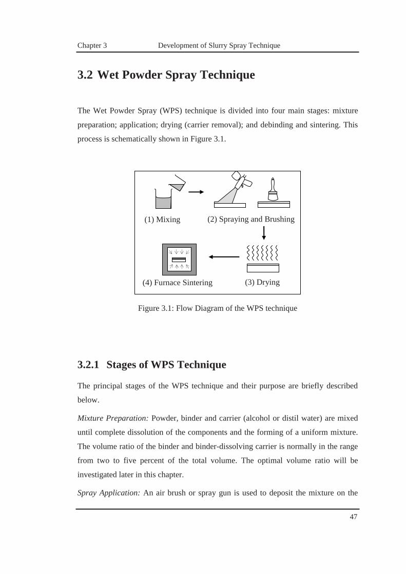
3.2 Wet Powder Spray Technique
The Wet Powder Spray (WPS) technique is divided into four main stages: mixture
preparation; application; drying (carrier removal); and debinding and sintering. This
process is schematically shown in Figure 3.1.
Figure 3.1: Flow Diagram of the WPS technique
3.2.1 Stages of WPS Technique
The principal stages of the WPS technique and their purpose are briefly described
below.
Mixture Preparation: Powder, binder and carrier (alcohol or distil water) are mixed
until complete dissolution of the components and the forming of a uniform mixture.
The volume ratio of the binder and binder-dissolving carrier is normally in the range
from two to five percent of the total volume. The optimal volume ratio will be
investigated later in this chapter.
Spray Application: An air brush or spray gun is used to deposit the mixture on the
(2) Spraying and Brushing
(3) Drying
(1) Mixing
(4) Furnace Sintering

Chapter 3 Development of Slurry Spray Technique
48
substrate to be coated. Properties such as particle size, density and ratio of solid to
liquid play an important role in this deposition stage. Their influence can be
controlled by adequate selection of parameters of the deposition technique (e.g.
pressure, distance, flow rate for the spray gun deposition).
Drying (Carrier Removal): The drying stage starts immediately after the deposition
of the mixture solution. The mixture is normally deposed on the substrate in a semi-
dry condition so that any uncontrolled dripping and wetting can be avoided. The
deposed coatings using WPS technique have a thickness range from 20 to 200 µm.
The drying process for this range of thicknesses is normally from half an hour to two
hours in open air in ambient humidity (~40%), depending on the thickness of the
coating deposited.
Debinding and Sintering: A binder is used to hold the deposited coating together
homogeneously, and prevent cracking during the drying process. However, the
presence of binder in the coating during the sintering stage is undesirable as it
normally leads to cracking and other coating defects. Therefore, prior to sintering of
the deposited ceramics, the binder must be removed from the coating. Debinding and
sintering can both be completed in the same furnace. The debinding involves heating
the coated specimen up to 400°C and normally holding for 2 hours or more, during
which the binder slowly vaporises from the coating. The temperature is then
increased until the desired temperature is reached, at which time the TBC is sintered.
Sintering temperatures are dependent on the substrate and coating properties, which
will be further investigated and discussed in this chapter. Sintering times are
normally limited to within fifteen hours as longer times can increase the risk of
cracking of the coating [Ruder, Buchkremer, Jansen, Malléner and Stöver, 1992].

Chapter 3 Development of Slurry Spray Technique
49
3.2.2 Literature Review – Previous Results
Typical results of the application of the WPS to fabricate ceramic coatings will now
be critically discussed based on the work by Ruder et al. [1992]. In this work, the
coatings were fabricated with a base mixture consisting of Zirconia (ZrO2) and
Nickel (Ni) powders. Incoloy 800 substrate was coated with a double layer of the
mixture deposited on both sides of the specimen. Between the application of the first
and second layer, the initial layer was left at ambient temperature to make sure that
the water component of the deposited coating will be fully evaporated. Once the
layers were free of moisture, the deposed ceramic layers were then sintered at
1300°C in a furnace, where the specimens were placed in a vertical position fully
imbedded in alumina sand. After sintering, specimens were taken and prepared for
cross sectional observation and micro-examination. The most notable feature is
rather high volume porosity, which reaches approximately 45 %. The high porosity
was explained by poor control of the spraying conditions. Since the sprayed mixture
was deposited in semi-dried conditions, the powder particle was interconnected by
the organic binder, which had a large volume fraction. The ceramic coating lacked a
fluid medium; where the particles were not able to migrate and rearrange to form a
more compact configuration. However, as noted in [Dahl, Kaus, Zhao, Johnsson,
Nygren, Wiik, Grande and Einarsrud, 2007], the problems with the densification of
the ceramic coating fabricated by WPS can be partially avoided by a better control of
the spraying and longer sintering times.
Micro-examinations of SEM reveal a smooth and continuous morphology along the
sintered particles. Another interesting observation is that the brush technique of the
deposition resulted in a much more uniform coating thickness rather than air gun
deposition. Further, some qualitative mechanical tests were conducted for the
fabricated coatings, such as scratching and peeling, demonstrating a reasonably good
adhesive strength and scratch resistance of the coating fabricated with WPS.

Chapter 3 Development of Slurry Spray Technique
50
3.2.3 Summary
The WPS technique proposed by [Ruder, Buchkremer, Jansen, Malléner and Stöver,
1992], for fabrication of thin ceramic coatings, has shown to be a very promising
technique for manufacturing a low cost TBCs without the need of sophisticated
equipment. However the technique that was suggested almost two decades ago has
many drawbacks. The fabricated coatings were generally of very poor quality with
unacceptably high levels of the porosity. To achieve a minimum required quality
with the WPS technique, Ruder suggested to use longer sintering times and a better
control of the ceramic powder deposition. For research conducted by Ruder it was
concluded that the WPS technique required further research, development and
experimentation, before the WPS could become a viable option for fabricating TBC.

Chapter 3 Development of Slurry Spray Technique
51
3.3 Development of WPS Technique
The initial step in development of the fabrication technique was to reproduce the Wet
Powder Spray (WPS) technique [Ruder, Buchkremer, Jansen, Malléner and Stöver,
1992] and identify the range of fabrication parameters that could be changed and
examined with the main objective being the improvement of the quality of the
coating. At the initial stage, an extensive literature search was conducted on coating
materials, deposition regimes and mechanisms of sintering of ceramics. In this
section, each aspect of the manufacturing process will be examined and various
options potentially leading to improvement of the quality of the coating will be
discussed.
3.3.1 Fabrication Parameters - Materials
The following section examines the materials and constituents that could be used for
the solution mixture to improve the quality of the deposition stage. The solution
mixture consists of ceramic powder, dispersants and organic binders. In addition, the
substrate material that the coating is to be applied to plays a key role in the selection
of the coating constituents, thus, it is also discussed here.
Powders – Ceramic
Ceramics are ideally suited as a base for TBC due to their high melting temperatures,
and exceptionally low thermal conductivity [Choi, Zhu and Miller, 2005]. The
physico-mechanical properties of ceramics used for fabricating TBC, typically by
Flame Spray techniques, are well investigated and widely available in the literature.
However, for use with the WPS technique the ceramic powder must also posses
some additional characteristics, which are critical for the quality of the final coating.
These include the ability to be dispersed within slurry solution and sintered at

Chapter 3 Development of Slurry Spray Technique
52
relatively low temperature. In addition, the deposited and sintered ceramics have to
generate low levels of residual stresses, which are critical for WPS.
In the previous chapter, large ranges of ceramics were found to be available for
fabricating TBC; these include conventional ceramic compounds, chlorites, and
pyrochlore to rare earth oxides. Rare earth oxides are particularly promising
materials for use as a TBC, due to the low thermal conductivity and high thermal
expansion inertness [Cao, Vassen and Stoever, 2004]. Based on the requirements
discussed above, Partially Stabilised Zirconia (PSZ) ceramics were selected by the
candidate for the use in WPS as they possess all the critical properties for this
technique, which was discussed in Chapter 2, section 2.4.4.
Powders – Metals
In the current section, the variation in the slurry composition of ceramic with a metal
powder will be introduced. The purpose is to reduce the mismatch between the
Coefficient of Thermal Expansion (CTE). The Nickel powder selected by the
candidate, closely resembled the thermo-mechanical properties of the substrate
material (as seen further in this section). Selection of the Nickel powder effectively
reduces the residual thermal stresses experienced by the coating and the substrate, by
reducing the mismatch in the CTE [Zhang, Xu, Wang, Jiang and Wu, 2006].
Dispersants
To prevent agglomeration of the ceramics within the aqueous slurry solution, a
dispersant is required to be added to introduce repulsive ionic forces between the
powder particles via steric stabilisation [Greenwood and Kendall, 1999]. The total
amount of dispersant added to the slurry is dependent upon the mass ratio of ceramic
powder to mixing agent. At low mass ratios the electrostatic stabilisation is induced
by the mixing agent and is able to hold the ceramic in solution mixture.
Hydrolysed organic polymers are typically added as dispersants to form slurries.
Non-uniform polarised regions of the polymer molecules allow these organic

Chapter 3 Development of Slurry Spray Technique
53
compounds to graft themselves onto ceramic powder particles through ionic
exchange [Khan, Briscoe and Luckham, 2000].The trailing section of the polymer
molecules retains their ionic charge and repulses other powder particles encapsulated
by the polarised dispersant molecules [Khan, Briscoe and Luckham, 2000].
The dispersant chosen for the slurry based solution mixture was tetra sodium
pyrophosphate. This dispersant was chosen based upon studies by [Briscoe, Khan
and Luckham, 1998], successful use in the creation of yttria stabilised zirconium
beads during the sintering of a slurry mixture. The use of different dispersants led to
no significant changes in the solution mixture properties, such as viscosity and did
not significantly affect the quality of the fabricated TBC, which will be examined
further in the following section. With the use of the dispersant for the solution
mixture, a binder is also needed to hold all components together once the coating has
been applied to the substrate.
Binder
The binder has an integral function in the formation of sintered TBCs by maintaining
the structural integrity of the coating prior to sintering. In essence, the binder and
ceramic powder particles form a soluble composite as the ceramic powder is acting
as a reinforcement phase and the binder as a matrix phase. The binder needs to be
vaporised before sintering at temperatures lower than for sintering the ceramic
coating. This process of vaporising of binder is called debinding [Tanaka, Pin and
Uematsu, 2006]. If the debinding stage prior to sintering is omitted, contaminants
could form within the sintered ceramic microstructure. This would result in
significant degradation of the quality of the TBC and, potentially, cause premature
failure of the coating.
The binders for the WPS slurry were selected based upon past success with similar
studies using Yttria Stabilised Zirconia (YSZ). One study in particular showed
promising results in the manufacture of sintered YSZ beads [Roy, Bertrand and
Coddet, 2005] using a nylon based on a copolymer of styrene, acrylic ester or hydro

Chapter 3 Development of Slurry Spray Technique
54
soluble polyvinyl alcohol. These binders were therefore considered suitable by the
candidate for use with the WPS slurry.
Mixing Agent
Distilled water was used as the mixing agent throughout the experimental
development of the WPS technique. Ionic disassociation within the distilled water
provides a limited form of electrostatic stabilisation of the ceramic powder particles.
The pH of the slurry solution is therefore adjusted using sodium hydroxide or
hydrochloric acid to create a slightly alkaline solution. The distilled water is also
capable of being fully evaporated from the slurry without leaving any residue as all
dissolved salts are eliminated during distillation [Narita, Hébraud and Lequeux,
2005].
Substrate Material
Materials commonly coated in hypersonic and industrial applications materials were
considered for the substrate material in the initial stages of experimental
development. This enables comparison between TBC produced using the WPS to
existing techniques. The candidates include stainless steel, Inconel and aluminium.
High carbon steel was not considered due to corrosion issues during application of
the aqueous solution mixture prior to the evaporation stage.
It is desirable for the substrate material have similar CTE to that of the coating
material, to prevent development of thermal stresses during fabrication and
temperature excursions during operation. As ceramics typically have very low CTE,
the coatings produced on Stainless Steels (opposed to Aluminium Alloy) will be the
most resilient to cracking at fabrication stage and to thermal fatigue due to repetitive
thermal excursions. Typical material properties for various substrate materials are
displayed below.

Chapter 3 Development of Slurry Spray Technique
55
Table 3.1: Substrate material properties
Substrate Material Melting Point, °C
CTE, (x 10-6) 1/°C
Thermal Conductivity, W/mK
Aluminium Alloy 660 23.1 51.9
Stainless Steel 316 1400 10.8 16.2
Inconel 601 1610 12.8 9.8
From Table 3.1, the Inconel 601 was shown to have a low CTE and thermal
conductivity, which is beneficial for the reduction of the induced thermal stresses.
Inconel 601 also has high melting temperature and resilience to corrosion. For these
reasons Inconel is predominantly used for load-bearing structures in aerospace
applications [Song, Lee, Lee, Kim, Kim and Lee, 2002; Zhang, Li, Li, Zhang, Wang,
Yang and Li, 2008]. Therefore, for this investigation Inconel 601 was selected by the
candidate as the substrate material.
3.3.2 Mixture Preparation
The first stage of the WPS involves dispersing the slurry constituents within a mixing
agent to form an aqueous solution capable of being sprayed onto exposed surfaces.
The most important factors in this stage are the level of dispersion of the constituents
within the slurry and the final viscosity of the mixture.
Firstly, a dispersant is added to the slurry mixture to allow the ceramic powder to be
dispersed within the working fluid. The dispersion of the slurry components, i.e. the
ceramic powder and binder, is important in determining their ability to be used in the
fabrication of thermal barrier coatings via the WPS. All coating components must be
capable of being fully dispersed homogeneously within the working fluid medium, in
order to produce coatings with uniform mechanical properties.

Chapter 3 Development of Slurry Spray Technique
56
The pH of the slurry is a further aspect that can be controlled to assist the dispersion
of the ceramic powder within the mixing agent. In addition, if the pH level of the
mixture is too high, this may produce solutions with increased relative sediment
height (RSH) [Mahdjoub, Roy, Filiatre, Bertrand and Coddet, 2003]. Appropriate pH
levels must therefore be maintained to produce solution mixtures that are able to be
applied to the substrate by a spray gun.
The final viscosity of the slurry can be adjusted by varying the composition of the
mixture to allow the slurry to be sprayed. This is discussed below, along with further
details on the dispersion process.
Dispersion
The ability of a non aqueous solution to be dispersed uniformly within a fluid is
dependent upon the attractive Van der Waals forces between powder particles within
the slurry mixture [Briscoe, Khan and Luckham, 1998]. The presence of large inter
particle forces can cause agglomeration of the ceramic where powder particles group
together to form an insoluble sedimentary layer. The development of a sedimentary
layer within the slurry must be avoided due to the increased viscosity of the slurry
mixture and material inhomogeneity within the sprayed coating.
To effectively negate the attractive inter-particular forces, repulsive forces have to be
introduced, which will keep the ceramic particles in suspension. There are two major
methods of introducing these forces: electrostatic stabilisation and steric stabilisation.
Both methods utilise ionic forces between powder particles by assigning ‘like ionic’
charges to the particles. These repulsive ionic forces increase with the increased
proximity between powder particles, and are able to overcome the attractive Van der
Waals forces [Greenwood and Kendall, 1999].
Electrostatic stabilisation of the ceramic powder particles is achieved by adjusting
the pH of the mixing agent to create a polarised environment around the particles.
The polar environment strips oppositely charged ions from the powder particles,
therefore leaving the particles themselves with a like charge. Repulsive ionic forces

Chapter 3 Development of Slurry Spray Technique
57
are then induced between the ionised powder particles to prevent agglomeration [Lan
and Xiao, 2007].
Similar to electrostatic stabilisation, in steric stabilisation an ionic dispersant is added
to the slurry mixture to deter agglomeration of the powder particles. The dispersant
itself is a polymeric entity composed of long polymer units capable of forming
intermolecular bonds with the powder particles. The dispersant is grafted to the
powder particle surface where the ionic charge of the exposed polymer layers
provides a repulsive ionic force between the engulfed particles [Greenwood and
Kendall, 1999].
Optimum Viscosity
To produce a slurry mixture with an optimum viscosity, the composition of the
mixture is varied until the best quality deposited layer is achieved. Each component
in the slurry mixture has a varying degree of influence on the viscosity of the slurry
solution. The binder composition has the most significant effect on the viscosity of
the mixture and quality of the applied coating layer.
The viscosity of the slurry mixture is also an important parameter governing the
selection of the spray process used to apply the slurry mixture to the substrate
surface. That is, the ability of the spray apparatus to uniformly apply a slurry mixture
is dependent on the mixture’s viscosity. The effects of ceramic, binder and dispersant
composition on solution viscosity will be examined in the following section.
The following sections of this chapter outline the effects of the composition of the
ceramic powder (i) and binder (ii) on the overall solution viscosity. These viscosity
measurements adhere to ASTM standard D1200 – 05: Standard Test Method for
Viscosity by Ford Viscosity Cup. The apparatus for the experiments is a ford cup,
which is a cylindrical vessel with conical bottom leading to a drain orifice. The
viscosity is rated via the ford index as determined by the time required for the full
cylinder to completely drain.

Chapter 3 Development of Slurry Spray Technique
58
i. Viscosity Measurements – Ceramic and Metal Powder
The composition of the ceramic powder plays a major role in the quality of the
applied solution mixture using a spraying system. Viscosity experiments were
conducted by the candidate to determine the optimum percentage of ceramic powder
in the slurry mixture. The composition of the solution, other than the ceramic and
Nickel composition remain unchanged. The testing regime of the ceramic powder
compositions can be seen in Table 3.2.
Table 3.2: Testing of Ceramic Powder Compositions
Composition Test Binder (%) Dispersant (%)
ZrO2 (%) Ni (%)
1 4 0.4 33 66
2 4 0.4 66 33
3 4 0.4 100 0
Through experimentation with the variation of percentages of the powder
composition in the slurry, it was noted that viscosity decreases proportionally with
ceramic content in the slurry mixture. The results from the experiments can be seen
in Figure 3.2. They show that in the case of TBC with Functionally Graded (FG)
layers (discussed in section 3.4.1), it will be necessary to adjust the percentage of the
binder content to maintain optimum viscosity of around 25 mm2/s to minimise
porosity induction.
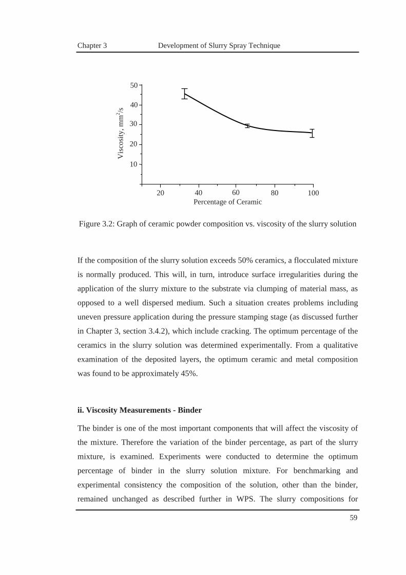
Chapter 3 Development of Slurry Spray Technique
59
Figure 3.2: Graph of ceramic powder composition vs. viscosity of the slurry solution
If the composition of the slurry solution exceeds 50% ceramics, a flocculated mixture
is normally produced. This will, in turn, introduce surface irregularities during the
application of the slurry mixture to the substrate via clumping of material mass, as
opposed to a well dispersed medium. Such a situation creates problems including
uneven pressure application during the pressure stamping stage (as discussed further
in Chapter 3, section 3.4.2), which include cracking. The optimum percentage of the
ceramics in the slurry solution was determined experimentally. From a qualitative
examination of the deposited layers, the optimum ceramic and metal composition
was found to be approximately 45%.
ii. Viscosity Measurements - Binder
The binder is one of the most important components that will affect the viscosity of
the mixture. Therefore the variation of the binder percentage, as part of the slurry
mixture, is examined. Experiments were conducted to determine the optimum
percentage of binder in the slurry solution mixture. For benchmarking and
experimental consistency the composition of the solution, other than the binder,
remained unchanged as described further in WPS. The slurry compositions for
Vis
cosit
y, m
m2 /s
Percentage of Ceramic
10
20
30
40
20 40 60 80 100
50

Chapter 3 Development of Slurry Spray Technique
60
viscosity experiments can be seen in Table 3.3.
Table 3.3: Viscosity measurements of the solution mixture for various binder
compositions
Test Ceramic Powder (%) Binder (%) Dispersant (%)
1 45 2 0.4
2 45 3 0.4
3 45 4 0.4
4 45 5 0.4
From the experimentation of the variation of percentages of the binder, it was
observed that the viscosity of the slurry mixture increases roughly linearly with the
percentage of binder. The results of the tests conducted can be seen in Figure 3.3.
Figure 3.3: Graph of binder percentage versus viscosity for the slurry solution. Error
bars represent maximum and minimum values obtained
Vis
cosi
ty, m
m2 /s
20
40
60
80
2 3 4 5Percentage of Binder
100
Chapter 3 Development of Slurry Spray Technique
61
If the binder percentage of the slurry solution was 2 % or less, the slurry mixture
became excessively fluidic, preventing its application the substrate with the current
spray equipment. If the percentage of binder in the slurry solution exceeded 4 %,
agglomeration in the slurry mixture increased such that the mixture was too
flocculated to be applied with the spray gun. Therefore, the used percentage of binder
used in the solution was determined to be 3 %.
3.3.3 Spray Application
The application of the aqueous slurry mixtures to substrate surfaces is conducted
directly by atomising the slurry within a pressurised air stream before being
projected upon the substrate surface. The spray process can be conducted utilising
pre-existing general spraying techniques and equipment allowing simple application
of the slurry to the substrate. Importantly, spray application of the coating offers the
opportunity to coat surfaces with irregular or complex geometries, and large surface
areas, which is important specifically for aerospace applications.
Spray Gun Selection
In order to achieve sufficient atomisation, the slurry has to be either drawn up from
below the conventional feed spray gun or fed from the top down into the nozzle from
the gravity feed. In order to achieve sufficient atomisation with siphon feed, greater
air pressure must be used in order to attain a strong enough vacuum to pull the slurry
up the feeding tube from below. The main problem with the siphon feed spray gun is
the requirement of high pressure, which is the main limitation for their use in High
Velocity, Low Pressure (HVLP) systems. It is much more difficult to keep low air
pressure and achieve adequate vacuum, with varying paint hopper sizes. Unlike the
siphon fed system, the gravity feed spray gun requires less air pressure to atomize the
solution mixture.

Chapter 3 Development of Slurry Spray Technique
62
Spraying with less air pressure has the advantages of less overspray, less waste and
greater control during application of the slurry. For the siphon fed spray gun, it is
possible to achieve atomisation at lower air pressures by pressurising the cup. For
application in the current research, a gravity fed spray gun was selected by the
candidate to apply the slurry-based coatings.
Spraying Techniques
Spraying techniques for the WPS closely follow those used in traditional spray
coating applications. The aqueous slurry is fed into a high velocity air stream via
small tube orifices and directed at a target surface to be deposited. As the slurry is
fed into the air stream via small orifices it is atomised, where the fine slurry mixture
is initially disassociated into small discrete molecules by shear forces generated
during introduction to the turbulent airflow. Reduction of the disassociated molecule
size allows a finer distribution of the sprayed coating along the target substrate.
However this reduction comes at the cost of increased slurry losses to spray
dispersion in the surroundings. The size of the disassociated slurry molecules is
controlled by the pressure and thus velocity of the air stream. Equipment utilised
during the spray process included a standard variable pressure air compressor and
gravity fed paint spray gun.
3.3.4 Drying (Carrier Removal)
The evaporation of binder out of the sprayed coating slurry represents an important
stage of the WPS where the wet coating layers remain in a fragile state until the
binder and water has fully evaporated. Once the stage is completed, the sintering
stage is able to commence. During this period the coating is susceptible to
disturbance from both, stresses as a result of external forces and stresses produced by
the evaporation of the water and binder.

Chapter 3 Development of Slurry Spray Technique
63
Evaporation Mechanism
The evaporation mechanism of water from the sprayed coating slurry is a lateral
drying process where, in the case of coatings sprayed on flat substrates, dry areas
first develop along the coating edges and, propagate inwards towards the centre of
the coated specimen. The evaporation process involves three distinct slurry stages as
shown in Figure 3.4. The first stage reflects the water-supersaturated conditions of
the coating, where the water composition is greater than that of the saturated region
and allows the powder particles to migrate freely within the slurry media. The second
stage is considered ‘fully saturated’ where the water content within the slurry fills all
pore space between the coating particles. The third stage refers to the dried powder
state, when the water has fully evaporated from the slurry to form a packed
arrangement of powder particles.
Figure 3.4: Slurry regions during evaporation
1. Super-Saturated Region 2. Saturated Region
3. Dry Saturated Region

Chapter 3 Development of Slurry Spray Technique
64
Prior to evaporation the entire sprayed coating represents a single water-
supersaturated region. During evaporation water is initially evaporated over the
entire coating surface. However the rate of evaporation is greatest at the coating
edges due to the greater exposed area of the coating. The edges develop into
saturated regions and continue to be evaporated, however, as the saturated regions
continue to evaporate, water is drawn to the saturated regions from the water-
supersaturated regions by capillary forces [Tanaka, Pin and Uematsu, 2006]. The
saturated regions then shrink inward toward the centre of the coating as dry regions
begin to form on the coating edges. Once all water-supersaturated regions have
developed into saturated regions, dry regions advance towards the coating centre
until the coating is fully evaporated.
After evaporation the coating is left as a continuous arrangement of loosely packed
powder particles. This arrangement is commonly described as a ‘green form’ or
having a ‘green body’ referring to the evaporated, but not yet sintered state. To
increase the strength of the green form a binder is added to the slurry mixture to bond
the evaporated powder particles together [Tanaka, Pin and Uematsu, 2006]. The
powder particles combine to form a composite with the binder acting as a matrix
phase to stabilise the powder particles substitute as a particulate phase as seen in
Figure 3.5. Prior to coating application, substrate surface preparation is needed to
prevent any contaminants during the spraying stages.

Chapter 3 Development of Slurry Spray Technique
65
Figure 3.5: Binder acting as matrix phase within powder/binder composite
Surface Preparation
Proper surface preparation prior to spraying is crucial to the integrity of the TBC.
Specific steps are required to be undertaken in order for the coating to perform to
optimum standards. The amount of time used for surface preparation may account for
just over 50% to complete the fabrication of the TBC [Berndt and Lenling, 2004].
Therefore, substrate surface preparation represents substantial investment,
considering the time and labour required during fabrication of TBC.
From the literature, it was concluded that sand blasting the substrate surface before
application is the preferred method, as opposed to sanding the surface [Kawamura,
Okado, Nishio and Suzuki, 2004]. Sand blasting removes all the grit, as well as
creating a very porous surface, enabling the solution mixture to seep into the pores of
the substrate surface during the spraying stage. The solution seeping into the pores
assists the coating to bond to the substrate during the sintering stage. The type of
bonding that occurs between the substrate and the coating is known as ‘diffusion
bonding’ [Bernard-Granger, Monchalin and Guizard, 2007].
Surface preparation helps promote bonding between coating and the substrate;
however, the bonding will be adversely affected by substrate thickness variations,
which would result in uneven application of the slurry solution. Uneven substrate

Chapter 3 Development of Slurry Spray Technique
66
surface can result in failure of the ceramic coating, if not properly addressed during
substrate preparation prior to coating. These issues are of concern during the pressure
stamping stage (discussed in the current Chapter, section 3.4.2), as the uneven
surface will cause specific areas to have non-uniform pressure applied to the surface,
causing uneven contact and growth of grain boundaries between the ceramic and
Nickel powder particles, and the metallic substrate. This is crucial during the
fabrication of the TBCs, as this phenomenon affects the stress distribution during the
sintering stage. These stress concentrations act as the catalyst for the coating failure,
leading to cracking and spallation of the coating.
Formation of Stress during Evaporation
During the initial development of the WPS, TBCs with thicknesses of between 1-2
mm were sprayed onto the metallic substrates, and allowed to evaporate under
ambient atmospheric conditions. During evaporation of the sprayed slurry coatings,
cracks were observed to develop within the semi-dried coating as seen in Figure 3.6.
Cracks initially developed along boundary edges of the partially dried coating before
propagating inwards to the centre of the coating surface.
Figure 3.6: Cracking within evaporated coating of excessive thickness

Chapter 3 Development of Slurry Spray Technique
67
The development of cracks within the evaporating slurry coating can be attributed to
the relief of stress resulting from the reduction of the coating surface thickness
during evaporation. As water is evaporated from the TBC, the coating volume
decreases, however, the coating itself is constrained by the substrate, which restricts
lateral reduction of the coating volume. Therefore while the coating is allowed to
reduce in thickness, lateral stresses are introduced by the substrate to the coating as
the water evaporates.
With adequate water composition these lateral stresses are relieved by viscous flow
of the slurry. After sufficient evaporation, the coating begins to form a continuous
particle structure held together by attractive van der Waals forces capable of
supporting the lateral stress [Lan and Xiao, 2007]. As evaporation continues, the van
der Waals forces increase as the powder particles are drawn into closer proximity by
the shrinking coating volume. Cracking of the evaporated coating occurs where the
lateral stress produced by the reduced coating volume becomes greater than the local
cohesive strength of the coating. Capillary forces during evaporation complement the
lateral stresses induced via volume reduction of the coating. Investigation by [Lan
and Xiao, 2007], determined the maximum lateral stresses that occur when the
coating transitions from a fully saturated state to a dry state, where the capillary
forces are maximised. The volume reduction and lateral stress profile for Yttria
partially stabilised zirconium slurry coatings are shown below in Figure 3.7 for a
decreasing residual water content of the coating [Lan and Xiao, 2007].
Two major factors affecting the ability of the evaporated coating to resist the lateral
stresses induced during the evaporation stage include the surface tension of the slurry
solution and the coating particle size. To minimise capillary forces during
evaporation, slurries with small surface tensions are preferred to decrease the
resultant lateral stresses produced during evaporation of the coating. By increasing
powder particle sizes, an increase in van der Waals forces between particles can be
achieved, leading to a higher cohesive strength of the evaporated coating.

Chapter 3 Development of Slurry Spray Technique
68
Figure 3.7: Volume reduction and lateral stress within YSZ for decreasing water
content
An alternative approach to prevent cracking of the evaporated slurry coating is to
utilise smaller coating thicknesses to reduce the lateral stresses developed during
evaporation. Smaller thicknesses lead to a reduced initial layer volume per unit area
and thus reduce lateral stress generation caused by the constrained volume reduction
of the coating. Coating thicknesses greater than 150 �m, were observed to crack
during the evaporation stage, as seen in Figure 3.6. The optimum coating thicknesses
were found to range from 50 to 150 �m. For these coating thicknesses, cracking of
the coating surface during the evaporation stage was minimised.
Coating
Volume
Slurry water composition, %vol
Late
ral S
tress
, MPa
Coa
ting
Vol
ume,
% o
f ini
tial
40 30 20 10 00
20
40
60
80
100
0
0.4
0.8
1.2
1.6
2.0

Chapter 3 Development of Slurry Spray Technique
69
3.3.5 Debinding and Sintering
Before sintering of a green body can begin, an initial debinding process is undertaken
to remove the binder component from the coating. The binder must be removed from
the coating microstructure to prevent contamination within the final sintered coating.
Contamination of the coating microstructure includes either the introduction of
inclusions within the coating material, such as dust particles or surface lubricants, or
the formation of an additional ceramic phase.
Inclusions within the coating microstructure develop from the concentration of the
binder within porous regions of the coating during sintering. As grain boundaries
grow between powder particles during sintering, pores form between the coalescing
powder particles. The binder is driven into the porous regions ahead of the advancing
grain boundaries where, under the increased pressure and high temperature
environment, the binder is able to transform into a distinct particulate within the
coating microstructure [Konyashin, 2001]. These inclusions form areas of stress
intensification and are possible initiation points for coating failure during thermal
cyclic loading.
The debinding process involves combustion of the binder from the green body at
temperatures much lower than the sintering temperature of the ceramic powder.
Typically organic polymers, such as Polyvinyl Alcohol, are commonly utilised as
binding agents due to their low melting points of approximately 600°C, and ability to
form stable green bodies through the formation of secondary bonds between the
binder monomers and the ceramic powder particles.

Chapter 3 Development of Slurry Spray Technique
70
Sintering
The sintering stage of the WPS is the point at which the evaporated slurry coating is
transformed from a weak green body to a solid coating able to resist high
temperatures and corrosive environments. The sintering process of the powder
particles transitions between three distinctive periods as depicted in Figure 3.8.
Figure 3.8: Powder coalescence during sintering
Initially, the deposited and dried powder represents a loosely separated pack of
powder particles with few contact regions. With the application of thermal energy,
the grain boundaries expand along these contact areas to form connected regions
between the particles. As more thermal energy is supplied, the grain boundaries
continue to create a spherical pore within the final microstructure [Choi, Zhu and
Miller, 2005]. The principal effect that drives the sintering process is the reduction in
exposed surface area, and consequently the surface energy, of the powder particles,
in comparison to their original unsintered states [Bernard-Granger, Monchalin and
Guizard, 2007].
Sintering of a specimen can be conducted using a variety of methods. Traditionally
sintering is performed using high temperature ovens or kilns, which have an
advantage over other sintering methods as the specimen can be sintered in a
Unsintered Semi - Sintered Fully - Sintered

Chapter 3 Development of Slurry Spray Technique
71
controlled thermal environment at a wide range of temperatures for any time duration
required. Another method involves using high intensity lasers to sinter thin material
volumes. In this case sintering takes place for very short durations under very high
temperatures in a localised region on the surface of the specimen. Lastly sintering
can also be conducted on a specimen using a direct combustion stream, such as oxy-
acetylene or propane. Direct combustion stream temperatures can reach up to 3000°C
however, while being the simplest sintering method, creating a uniform heat flux on
the specimen is difficult and the control of the sintering temperature range is limited.
Sintering Temperatures
Sintering temperatures required to sufficiently promote grain growth amongst
powder particles typically require temperatures above 70% of the melting
temperature of the material (in Kelvin). This temperature is below melting
temperature, but is high enough to allow solid state sintering [Degarmo, Black and
Kohser, 2003]. However, for cases where two dissimilar materials are to be sintered,
the sintering temperature must be increased to where liquid state sintering occurs.
Liquid state sintering is essentially in a semi molten state to allow the material to fill
the voids between the two different materials. Theoretically, minimum sintering
temperatures occur below this limit, however as sintering times are inversely related
to the sintering temperatures [Choi, Zhu and Miller, 2005], the associated long
sintering durations limit the practicality of using such low sintering temperatures.
High Temperature Furnace
A high temperature furnace was used to sinter specimens, which were produced in
tandem with the oxy-acetylene torch. The furnace provides a uniform heat
distribution over the slurry coated substrates, minimising the induced thermal
stresses from differences in temperature. In contrast, the oxy-acetylene torch creates
uneven temperature distribution over the coating throughout the sintering stage. The
specimens sintered using the high temperature furnace allowed comparative

Chapter 3 Development of Slurry Spray Technique
72
assessment between the two sintering methods on the quality between the Slurry
Sprayed TBC.
3.3.6 Summary
The WPS technique was found able to successfully fabricate ceramic TBCs. Through
analysis of the WPS technique, the fabrication stages were refined allowing
production of the TBC. In the WPS technique, the solution mixture was applied to
the substrate in a semi-dry state. The coating relies on the binder to act as the
interlayer bonds between the particles, which were responsible for the high levels of
porosity in the coating. After examination of the spraying stage, a dispersant was
included in the slurry solution, to aid in the powder dispersion, allowing the slurry to
be produced in a more aqueous medium. Therefore, the solution was applied as a wet
medium, allowing the particles to migrate freely in the slurry medium, reducing the
porosity of the TBC and creating a denser coating. This in turn reduced the sintering
times needed for densification of the coating. However, the produced TBC spalled
during and after sintering. Qualitative adhesion tests (scratching and peeling) have
shown that the coating was still easily damaged, and the overall quality of the coating
was poor.
It was concluded the technique required further development, research and
experimentation, before the technique could fabricate TBC without coating failure
during the fabrication stages. The following section aims to address the majority of
these issues with the WPS technique. Further research and experimentation was
conducted into each aspect of the WPS technique, leading to the development of the
SST.

Chapter 3 Development of Slurry Spray Technique
73
3.4 Slurry Spray Technique
The Wet Powder Spray (WPS) technique has been shown to be capable of producing
TBC, however, many problems still exists during the fabrication stages of the Slurry
based technique. These problems include failure of the produced Slurry based TBC,
with regards to spallation of the coating, during, after sintering, long sintering times,
and general problems which arose during the fabrication process. These problems
and issues are addressed with the Slurry Spray Technique (SST).
An overview of the SST can be seen in Figure 3.9. The SST incorporates additional
steps throughout all the stages of the fabrication process, which include a multi-layer
spraying stage, pressure stamping stage and the use of an automated sintering
platform.
Figure 3.9: Stages of the SST
After initial tests conducted by the candidate, it was observed that thermal cycling
tests on TBC specimens fabricated using the SST were unable to withstand exposure
(2) Multilayered Spraying (1) Mixing
(4) Stamping
Pressure
(3) Drying(5) Torch and
Furnace Sintering

Chapter 3 Development of Slurry Spray Technique
74
to thermal cycles. Upon inspection of the failed specimens, large spall regions along
the substrate and coating interface were observed over the coating surface area. The
TBC failure, through spallation of the coating, was the result of stresses induced by
the thermal expansion mismatch between the substrate and coating material during
the stages of fabrication. To reduce the stresses associated with the mismatch in the
Coefficient of Thermal Expansion (CTE) of the coating material and substrate,
Functionally Graded Thermal Barrier Coatings (FG–TBCs) were introduced
[Polanco, Miranzo and Osendi, 2006].
Functionally Graded Thermal Barrier Coatings
To produce FG–TBCs, the compositions of the coating were varied using a metal
additive with a CTE similar to that of the substrate. Metal rich regions were
deposited close to the substrate surface, altering the effective difference in the
coefficient of thermal expansion within that locality. At regions further away from
the substrate the metal composition was reduced, allowing the material properties of
the ceramic to dominate. The net result was a coating with a varied thermal
expansion coefficient over the thickness of the Functional Grading Coating. The
presence of a large coefficient differential at the coating and substrate interface is
avoided by varying the thermal coefficient gradually through the coating. Thus the
thermal stress is distributed more evenly through the coating thickness, effectively
reducing the maximum induced thermal stress.
During fabrication of the FG–TBCs using the SST, Nickel powder was selected as an
appropriate grading material. The Nickel powder has a CTE of 12 x 10-6 1/°C, which
is sufficiently close to that of the Inconel substrate material. This effectively
minimises the difference between the CTE of the coating layers and the substrate
material. Additionally the inclusion of Nickel within the ceramic coating does not
lead to the creation of additional phase variations within the coating microstructure
of the TBC material [Polanco, Miranzo and Osendi, 2006].
Experiments were conducted by the candidate to determine the optimum percentage

Chapter 3 Development of Slurry Spray Technique
75
of ceramic and Nickel powder for the slurry solution mixture. The composition of the
solution, other than the Zirconia and Nickel remain unchanged as described in the
original technique, and is illustrated in Table 3.4. The variation in the composition of
ceramic and metal powders was chosen for each test, to minimise thermal stresses.
Table 3.4: Testing of Graded Compositions
Composition Test No. Layers
Section ZrO2 (%) Ni (%)
Top 50 50 1 Double
Base 100 0
Top 33 66
Mid 66 33 2 Triple
Base 100 0
Top 25 75
Mid 1 50 50
Mid 2 75 25 3 Quadruple
Base 100 0
Fabrication of two and three layered coatings proved successful, with both the
coatings fabricated without spallation and delamination, during and after the
sintering stage. However, the four layered coating spalled during and after sintering
stage, which was limited by the thickness of the coating. From qualitative analysis,
the maximum numbers of coating layers was found to be three layers.

Chapter 3 Development of Slurry Spray Technique
76
3.4.1 Spraying
During application of the slurry to the substrate, it was observed that there was a
substantial amount of excess slurry solution. These wastages can be attributed to the
design of the gravity fed spray gun. The gravity fed spray gun has limitations in the
directions and angles the slurry can be applied to the substrate as it was designed to
apply sprayed material to vertical standing structures. The application of the slurry
solution requires the substrate to be positioned horizontally. Therefore excess slurry
mixture remained in the paint pot, unable to be sprayed to the structure. It was
concluded that the current spray gun was highly inefficient and added unnecessary
cost to the spraying stage of the SST. These issues led to the selection of a spray gun
which addressed the aforementioned problems.
Spray Gun
The Anest Iwata gravity fed spray gun (RG.3L.3C) has a fluid nozzle size of 1.0 mm
and a fluid output of 80 ml per minute, as per manufacturer’s specifications. The
sprays gun has a fan pattern which covers an area of 35 mm and is able to achieve a
fine atomisation spray. The utilisation of the Anest Iwata gravity fed spray gun has
the benefit of the ability to spray 90 degrees perpendicular to the surface of the
substrate. The spray gun is equipped with a side mounted gravity pot that can be
rotated thus allowing for flexibility in all angles of spraying: horizontal, vertical and
hard to reach angles. This helped to overcome the issues of wastage of the slurry
mixture and, at the same time, allow the slurry mixture to be applied to surface
structures without the limitation of vertical application. The gun is also equipped
with a 130 ml pot ideal for spraying on smaller surface areas or lesser substrates.
Wet Interlayer
The base layer must be fully evaporated prior to coating of any subsequent ceramic
layer, otherwise a wet interlayer will be present. This will affect the pressure
stamping stage (discussed in section 3.4.2), creating a dark indention mark with

Chapter 3 Development of Slurry Spray Technique
77
loosely packed particles visible in the coating and, in turn, interferes with the
sintering stage. The loosely packed particles of the coating is caused by the
compaction of the porosity left by evaporated water between the layers, which can be
seen in Figure 3.10.
Figure 3.10: Stamped substrate with mark of wet inter-layer.
3.4.2 Pressure Stamping
Before pressure stamping of the coating was introduced into the fabrication
procedure, long sintering times were experienced in order to adequately sinter the
coatings. The long sintering times were attributed to the remoteness of the powder
particles in respect to each other within the unsintered body, which increased the
thermal energy that was required to grow the grain regions prior to intersection of the
grain boundaries and coalescence [Hirvonen, Nowak, Yamamoto, Sekino and
Niihara, 2006]. As a result, extended sintering durations were required to initially
supply thermal energy to grow the grain regions before coalescence could begin.
To reduce the sintering times required to grow the grain boundaries prior to
coalescence, the overall proximity of the powder particles to each other, needed to be
Wet inter-layer

Chapter 3 Development of Slurry Spray Technique
78
increased. Hence, an increase in the contact area between the powder particles was
required. To increase the contact areas between powder particles a pressure force is
applied utilising a universal pressure stamping machine. The application of pressure
to the coating results in mechanical densification, as shown in Figure 3.11, in
contrast to the surface diffusion densification achieved through sintering.
Figure 3.11: Densification during pressure application
Tests were conducted to determine the optimum compression pressure to be applied
to the coating surface. For benchmarking and experimental consistency, the
composition of the solution remained constant as described in the WPS technique,
section 3.3.2.
The aim of the following experiments was to determine the most optimal pressure to
decrease the sintering times without causing any damage to the coating. The
experiments conducted with compression pressure ranging from 20 to 60 MPa, as
seen in Table 3.5.
Table 3.5: Testing of surface pressures
Test 1 2 3 4 5
Pressure [MPa] 20 30 40 50 60

Chapter 3 Development of Slurry Spray Technique
79
From a qualitative examination of the experiments conducted, it was observed that
the compression pressures that ranged from 20 to 30 MPa showed improved
coalescence of grain boundaries, as shown in Figure 3.12. With the application of
surface pressures of 40 to 60 MPa improved grain boundary growth was observed,
however during the sintering stages, spallation and delamination of the TBC was
seen along specimen surface.
The pressure stamping of the unsintered coating with the arrangement of powder
particles progressed from a loose configuration to densely packed volume with
reduced porosity. The reduction in porosity is visible in comparisons of Scanning
Electron Microscope (SEM) images of a pressure stamped and unstamped coating in
Figure 3.12. Essentially mechanical rather than thermal energy is utilised for the
coating densification. Once mechanical densification has occurred, continued
densification of the green body can begin through the sintering of the tightly packed
particle arrangement from the supplied thermal energy.

Chapter 3 Development of Slurry Spray Technique
80
Figure 3.12: SEM porosity comparison between 30 MPa pressed (top) and un-
pressed (bottom) coatings
3.4.3 Sintering
During the initial phase of the sintering stage, the binder is vaporised from the
coating surface using an oxy-acetylene torch, fixed above the centre of the specimen.
From examination of the coating surface, it was observed that the particles in the
centre of the coating showed a good coalescence between the ceramic powders.
However as the distance from the centre of the coating increased, the level of
coalescence between particles was observed to drop dramatically. From examination
of the sintering method of oxy acetylene, it was deduced that the coating was

Chapter 3 Development of Slurry Spray Technique
81
experiencing uneven heat distribution throughout the coating surface. With uneven
heat distribution lays a greater difference of temperature along the surface of the
coating, leading to the variation in the coalescence ceramic particles.
After examination of the various sintering durations, the coatings were observed to
be adequately sintered after 30 minutes. However the percentage of the
Zirconia/Nickel composition of the base layer is restricted by certain constraints,
which include the mismatch of thermo-mechanical properties, a source of thermal
stress, which normally leads to the spallation of the coating during the fabrication
stages. Moreover, if the Zirconia/Nickel content of slurry mixture exceeds fifty
percent, a flocculated slurry is produced which introduces surface irregularities
during application of the coating. These surface irregularities on the coating resulted
in uneven pressure application during pressure stamping stage of the SST. This
introduced stress concentrations within the surface of the coating, which eventually
led to cracking and spallation of the TBC during the sintering stage.
The current sintering method (oxy-acetylene torch) posed a major issue in the
development of the SST. With the variation in temperature along the coating surface,
thermal stresses are experienced along the surface resulting in greater chances of
spallation. Other sintering methods were considered to increase the coating
coalescence between the ceramic particles and apply a uniform heat distribution over
the coating surface, minimising the induced thermal stresses [Basu, Funke and
Steinbrech, 1999]. This led to the use of a high temperature oven and the
development of the automated sintering platform.
Automated Sintering Rig
To overcome the problems of uneven sintering of the TBC, an automated sintering
rig was designed by the candidate and fabricated at the University of Adelaide,
School of Mechanical Engineering. The sintering rig was designed to apply heat
uniformly to the surface of the coating, as opposed to from a stationary position
which focuses on the centre of the specimen. The design of the automated sintering

Chapter 3 Development of Slurry Spray Technique
82
rig consists of a platform, microcontroller package and a laptop for real-time
debugging of the automated software, as shown in Figure 3.13.
Figure 3.13: Automated sintering platform setup
Positional Oxy-Acetylene Torch
The first prerequisite of the automated sintering platform was that it allowed the
position of the oxy-acetylene torch to move freely, to enable the manipulation of the
flame position and height. This would take any changes in ambient temperature,
humidity and external forces into consideration. The automated sintering platform
allows the positioning of the oxy-acetylene torch along all three axes, allowing
substrates with various dimensions to be sintered
Sliding Platform
A sliding platform was designed such that the oxy-acetylene flame remained
stationary, while the substrate moved in a predetermined pattern on the sliding
platform, with the specimen being uniformly heated, as shown in Figure 3.14. The
platform can move in the X and Y direction, through the use of two stepper motors,
allowing substrates of various dimensions to be sintered. The position, distance and
speed of the stepper motors are controlled through a microcontroller package.
Laptop Microcontroller
Package
Automated Sintering Platform
Oxy Acetylene
Torch Holder

Chapter 3 Development of Slurry Spray Technique
83
Figure 3.14: CAD drawings of the moveable platform
Microcontroller Package
The microcontroller package contains a microcontroller and a motor controller,
connected to two stepper motors, which is attached to the rig. Information and
control is transferred into the microcontroller package from the laptop and
communicated to the rig. The sintering time can be set and adjusted using the
debugging software as well as the heating pattern, which can be set and modified to
the desired sintering characteristics.
The moving platform provides a uniform heat distribution to the coating surface
during the sintering stage. Figure 3.15 shows a typical heating pattern programmed
into the microcontroller, during use of the automated sintering platform for the
sintering stage of the SST. The heating pattern (as shown in Figure 3.15) used for the
sintering of TBC, produced coatings with greater levels of particle coalescence
throughout the coating surface. Along with the higher levels of particle coalescence,
fewer specimens were observed to spall during and after the sintering stage. This was
attributed to the even application of heat to the coating, effectively reducing the
residual thermal stresses of the coating. Since a noticeable improvement over the
original sintering method was observed, this sintering method and pattern was
adopted by the candidate for the fabrication of Slurry Based TBC over the use of the
oxy acetylene torch.

Chapter 3 Development of Slurry Spray Technique
84
Figure 3.15: Automated Sintering Rig Oxy Acetylene Torch Path
3.4.4 Development of Fabricating Parameters
After extensive research and experimentation in the fabricating stages of the Wet
Powder Spray (WPS) technique, the SST was developed. The developed technique is
comprised of five stages: slurry mixing, multi layered spraying, evaporation, pressure
stamping and sintering. The additional stage of pressure stamping was necessary to
reduce the long sintering times experienced with the original technique. In the
following section, each of stage of the SST will be summarised with the optimal
fabricating parameters of each stage shown.
Slurry Solution Mixture
Through experimental research and examination detailed in current and previous
sections (3.3.2), the optimum composition was determined for each of the key
components for the slurry spray mixture. The optimum percentage of ceramic and
Nickel powder, binder and dispersant determined is shown in Table 3.6.
Oxy acetylene Torch
Substrate
FinishStart

Chapter 3 Development of Slurry Spray Technique
85
Table 3.6: Optimum slurry mixture by volume
Ceramic and Nickel Powder Binder Dispersant Mixing Agent
45 % 3 % 0.4 % 51.6 %
Spraying process
The optimum parameters during the spraying process were identified after
experimental investigations of spraying parameters. These parameters include the
spraying height, compressor pressure and also the orifice size of the spray gun
nozzle, which are shown in Table 3.7 below. These parameters will directly affect
the area, thickness and the performance of the coating.
Table 3.7: Optimum slurry spraying parameters
Spraying Height Number of Grader Layers Coating Thickness
200 – 300 mm 2 – 3 50 – 150 µm
The most notable development of this stage was the addition of multilayered
spraying. This development effectively reduced the drying stresses during the
evaporation stage, allowing the fabrication of thicker coatings. The introduction of
FG–TBCs was observed to improve the coating’s resistance to failure during
fabrication by reducing the thermal stresses induced during the fabrication stage.

Chapter 3 Development of Slurry Spray Technique
86
Pressure Stamping
Compression pressures ranging from 10 to 60 MPa were systematically applied to
the coating specimens, and based upon coating failure during and after the sintering
stage, the optimum parameters were determined. Through examination of the
specimens after the pressure stamping stage, the optimum value of applied pressure
to the TBC specimen was determined to be 30 MPa.
Sintering
The introduction of the automated sintering rig effectively reduced the number of
specimen failures during the stages of fabrication, by minimising the thermal stresses
experienced by the TBC. With this sintering approach, significantly lower amounts
of coating failure occurring during the fabrication of the TBCs. This sintering
method was adopted for the fabrication of TBC with the SST over the oxy acetylene
torch.
3.4.5 Summary
From extensive investigation and research, the WPS progressed into the SST. With
the additional stage (pressure stamping) implemented in the SST, the increase in
quality of the produced TBC was evident with significantly lower coating failures
during the fabrication stage. The application of compression pressure to the
evaporated coatings and development of functionally graded coating layers was
found to greatly reduce sintering times and increase the coating resilience to peak
thermal stresses during and after the sintering stages. The peak thermal stresses were
reduced with the introduction of the automated sintering rig. This effectively reduced
the number of specimen failures during the stages of fabrication by minimising the
thermal stress experienced by the TBC. The primary differences between WPS and
SST are highlighted in Figure 3.16.

Chapter 3 Development of Slurry Spray Technique
87
(a) WPS
(b) SST
Figure 3.16: Technique Comparison of WPS and SST
(2) Multilayered Spraying (1) Mixing
(4) Stamping
Pressure
(5) Torch and Furnace Sintering
(3) Drying
(3) Drying (4) Torch Sintering
(2) Spraying (1) Mixing

Chapter 3 Development of Slurry Spray Technique
88
The addition of multi-layered spraying to the fabrication process, allowed the
production of FG–TBCs. This novel addition to the fabrication process opened up the
SST to a variety of applications. Therefore, FG–TBCs can be engineered to suit the
needs of the situation, and not limited by the material properties of the ceramic
coating.

Chapter 3 Development of Slurry Spray Technique
89
3.5 Conclusion
A literature review into current TBC fabrication techniques demonstrated that a niche
exists to benefit many industrial applications, as seen in Chapter 2, section 2.2. There
is a need for a new fabrication technique aimed at the depositing thermal protection
coatings over large complex surfaces in an economical manner.
The examination of the WPS technique was conducted through the analysis of the
previous experimental results conducted by [Ruder, Buchkremer, Jansen, Malléner
and Stöver, 1992], and new investigations. This led to the refinement of each of the
fabricating stages. These included the examination of the slurry solution mixtures,
spraying parameters, evaporation stages and sintering methods. While the WPS
technique were able to produce low cost TBCs, in terms of general structural
integrity, the coatings were of very low quality which include high levels of porosity
and low adhesive strength, which resulted in failure of the coating even during the
fabrication stages.
These deficiencies led to the modification of WPS technique and development of the
SST. The SST includes the new fabricating stages such as multi-layered spraying,
which allows the fabrication of FG–TBCs. With the addition of the pressure
stamping stage, the sintering times was reduced considerably and provide a higher
quality coating.
For the development of the SST, the effects of a number of fabricating parameters on
the quality of the coating were investigated and the optimal characteristics for every
stage of manufacturing determined through experimentation.